JP7560499B2 - OPTICAL METHODS AND SYSTEMS FOR LIGHT FIELD (LF) DISPLAYS BASED ON A TUNABLE LIQUID CRYSTAL (LC) DIFFUSER - Patent application - Google Patents
OPTICAL METHODS AND SYSTEMS FOR LIGHT FIELD (LF) DISPLAYS BASED ON A TUNABLE LIQUID CRYSTAL (LC) DIFFUSER - Patent applicationDownload PDFInfo
- Publication number
- JP7560499B2 JP7560499B2JP2021577364AJP2021577364AJP7560499B2JP 7560499 B2JP7560499 B2JP 7560499B2JP 2021577364 AJP2021577364 AJP 2021577364AJP 2021577364 AJP2021577364 AJP 2021577364AJP 7560499 B2JP7560499 B2JP 7560499B2
- Authority
- JP
- Japan
- Prior art keywords
- light
- diffuser
- display
- exemplary
- selc
- Prior art date
- Legal status (The legal status is an assumption and is not a legal conclusion. Google has not performed a legal analysis and makes no representation as to the accuracy of the status listed.)
- Active
Links
Images


Classifications
- G—PHYSICS
- G02—OPTICS
- G02B—OPTICAL ELEMENTS, SYSTEMS OR APPARATUS
- G02B30/00—Optical systems or apparatus for producing three-dimensional [3D] effects, e.g. stereoscopic images
- G02B30/20—Optical systems or apparatus for producing three-dimensional [3D] effects, e.g. stereoscopic images by providing first and second parallax images to an observer's left and right eyes
- G02B30/26—Optical systems or apparatus for producing three-dimensional [3D] effects, e.g. stereoscopic images by providing first and second parallax images to an observer's left and right eyes of the autostereoscopic type
- G—PHYSICS
- G02—OPTICS
- G02B—OPTICAL ELEMENTS, SYSTEMS OR APPARATUS
- G02B30/00—Optical systems or apparatus for producing three-dimensional [3D] effects, e.g. stereoscopic images
- G02B30/20—Optical systems or apparatus for producing three-dimensional [3D] effects, e.g. stereoscopic images by providing first and second parallax images to an observer's left and right eyes
- G02B30/22—Optical systems or apparatus for producing three-dimensional [3D] effects, e.g. stereoscopic images by providing first and second parallax images to an observer's left and right eyes of the stereoscopic type
- G02B30/25—Optical systems or apparatus for producing three-dimensional [3D] effects, e.g. stereoscopic images by providing first and second parallax images to an observer's left and right eyes of the stereoscopic type using polarisation techniques
- G—PHYSICS
- G02—OPTICS
- G02B—OPTICAL ELEMENTS, SYSTEMS OR APPARATUS
- G02B30/00—Optical systems or apparatus for producing three-dimensional [3D] effects, e.g. stereoscopic images
- G02B30/20—Optical systems or apparatus for producing three-dimensional [3D] effects, e.g. stereoscopic images by providing first and second parallax images to an observer's left and right eyes
- G02B30/26—Optical systems or apparatus for producing three-dimensional [3D] effects, e.g. stereoscopic images by providing first and second parallax images to an observer's left and right eyes of the autostereoscopic type
- G02B30/27—Optical systems or apparatus for producing three-dimensional [3D] effects, e.g. stereoscopic images by providing first and second parallax images to an observer's left and right eyes of the autostereoscopic type involving lenticular arrays
- G02B30/28—Optical systems or apparatus for producing three-dimensional [3D] effects, e.g. stereoscopic images by providing first and second parallax images to an observer's left and right eyes of the autostereoscopic type involving lenticular arrays involving active lenticular arrays
- G—PHYSICS
- G02—OPTICS
- G02B—OPTICAL ELEMENTS, SYSTEMS OR APPARATUS
- G02B30/00—Optical systems or apparatus for producing three-dimensional [3D] effects, e.g. stereoscopic images
- G02B30/20—Optical systems or apparatus for producing three-dimensional [3D] effects, e.g. stereoscopic images by providing first and second parallax images to an observer's left and right eyes
- G02B30/26—Optical systems or apparatus for producing three-dimensional [3D] effects, e.g. stereoscopic images by providing first and second parallax images to an observer's left and right eyes of the autostereoscopic type
- G02B30/30—Optical systems or apparatus for producing three-dimensional [3D] effects, e.g. stereoscopic images by providing first and second parallax images to an observer's left and right eyes of the autostereoscopic type involving parallax barriers
- G02B30/31—Optical systems or apparatus for producing three-dimensional [3D] effects, e.g. stereoscopic images by providing first and second parallax images to an observer's left and right eyes of the autostereoscopic type involving parallax barriers involving active parallax barriers
- G—PHYSICS
- G02—OPTICS
- G02F—OPTICAL DEVICES OR ARRANGEMENTS FOR THE CONTROL OF LIGHT BY MODIFICATION OF THE OPTICAL PROPERTIES OF THE MEDIA OF THE ELEMENTS INVOLVED THEREIN; NON-LINEAR OPTICS; FREQUENCY-CHANGING OF LIGHT; OPTICAL LOGIC ELEMENTS; OPTICAL ANALOGUE/DIGITAL CONVERTERS
- G02F1/00—Devices or arrangements for the control of the intensity, colour, phase, polarisation or direction of light arriving from an independent light source, e.g. switching, gating or modulating; Non-linear optics
- G02F1/01—Devices or arrangements for the control of the intensity, colour, phase, polarisation or direction of light arriving from an independent light source, e.g. switching, gating or modulating; Non-linear optics for the control of the intensity, phase, polarisation or colour
- G02F1/13—Devices or arrangements for the control of the intensity, colour, phase, polarisation or direction of light arriving from an independent light source, e.g. switching, gating or modulating; Non-linear optics for the control of the intensity, phase, polarisation or colour based on liquid crystals, e.g. single liquid crystal display cells
- G02F1/133—Constructional arrangements; Operation of liquid crystal cells; Circuit arrangements
- G02F1/1333—Constructional arrangements; Manufacturing methods
- G02F1/1335—Structural association of cells with optical devices, e.g. polarisers or reflectors
- G02F1/133528—Polarisers
- G02F1/133538—Polarisers with spatial distribution of the polarisation direction
- H—ELECTRICITY
- H04—ELECTRIC COMMUNICATION TECHNIQUE
- H04N—PICTORIAL COMMUNICATION, e.g. TELEVISION
- H04N13/00—Stereoscopic video systems; Multi-view video systems; Details thereof
- H04N13/30—Image reproducers
- H04N13/302—Image reproducers for viewing without the aid of special glasses, i.e. using autostereoscopic displays
- H04N13/307—Image reproducers for viewing without the aid of special glasses, i.e. using autostereoscopic displays using fly-eye lenses, e.g. arrangements of circular lenses
- H—ELECTRICITY
- H04—ELECTRIC COMMUNICATION TECHNIQUE
- H04N—PICTORIAL COMMUNICATION, e.g. TELEVISION
- H04N13/00—Stereoscopic video systems; Multi-view video systems; Details thereof
- H04N13/30—Image reproducers
- H04N13/302—Image reproducers for viewing without the aid of special glasses, i.e. using autostereoscopic displays
- H04N13/31—Image reproducers for viewing without the aid of special glasses, i.e. using autostereoscopic displays using parallax barriers
- H04N13/315—Image reproducers for viewing without the aid of special glasses, i.e. using autostereoscopic displays using parallax barriers the parallax barriers being time-variant
- H—ELECTRICITY
- H04—ELECTRIC COMMUNICATION TECHNIQUE
- H04N—PICTORIAL COMMUNICATION, e.g. TELEVISION
- H04N13/00—Stereoscopic video systems; Multi-view video systems; Details thereof
- H04N13/30—Image reproducers
- H04N13/356—Image reproducers having separate monoscopic and stereoscopic modes
Landscapes
- Physics & Mathematics (AREA)
- General Physics & Mathematics (AREA)
- Optics & Photonics (AREA)
- Signal Processing (AREA)
- Nonlinear Science (AREA)
- Engineering & Computer Science (AREA)
- Multimedia (AREA)
- Crystallography & Structural Chemistry (AREA)
- Chemical & Material Sciences (AREA)
- Mathematical Physics (AREA)
- Testing, Inspecting, Measuring Of Stereoscopic Televisions And Televisions (AREA)
- Liquid Crystal (AREA)
- Mobile Radio Communication Systems (AREA)
- Devices For Indicating Variable Information By Combining Individual Elements (AREA)
- Liquid Crystal Display Device Control (AREA)
Description
Translated fromJapanese本発明は、調整可能な液晶ディフューザ(LC)に基づいたライトフィールド(LF)ディスプレイのための光学的方法およびシステム関する。The present invention relates to an optical method and system for a light field (LF) display based on a tunable liquid crystal diffuser (LC).
関連出願の相互参照
本出願は、その全体が参照によって本明細書に組み込まれる、2019年6月28日に出願された、「OPTICAL METHOD AND SYSTEM FOR LIGHT FIELD (LF) DISPLAYS BASED ON TUNABLE LIQUID CRYSTAL (LC) DIFFUSERS」と題する、米国特許仮出願第62/868687号の非仮出願であり、米国特許法第119条(e)項の下において同特許仮出願からの利益を主張する。 CROSS-REFERENCE TO RELATED APPLICATIONS This application is a non-provisional application of and claims the benefit under 35 U.S.C. § 119(e) of U.S. Provisional Patent Application No. 62/868,687, entitled “OPTICAL METHOD AND SYSTEM FOR LIGHT FIELD (LF) DISPLAYS BASED ON TUNABLE LIQUID CRYSTAL (LC) DIFFUSERS,” filed June 28, 2019, which is incorporated by reference herein in its entirety.
人間の心は、部分的には各眼を方向付けるために使用された筋肉から信号を受け取ることによって、観察された物体の深度を知覚し、決定する。脳は、眼の相対的な角度方向を、決定される焦点の深度と関連付ける。正しい焦点キューは、観察された焦点面の外側の物体における自然なぼやけ、および自然な動的視差効果を生じさせる。正しい焦点キューを提供することが可能な3Dディスプレイの1つのタイプは、真の3D空間内に3D像を生成することができる、ボリュームディスプレイ技法を使用する。3D像の各「ボクセル」は、物理的に空間位置に配置され、その位置から観察者に向かって光を反射または放射して、視聴者の眼の中に実像を形成する。The human mind perceives and determines the depth of a viewed object, in part, by receiving signals from the muscles used to orient each eye. The brain associates the relative angular orientation of the eyes with the determined depth of focus. Correct focus cues produce natural blurring of objects outside the viewed focal plane, and natural dynamic parallax effects. One type of 3D display capable of providing correct focus cues uses volumetric display techniques, which can generate a 3D image in a true 3D space. Each "voxel" of the 3D image is physically located at a spatial location from which it reflects or emits light towards the observer to form a real image in the viewer's eye.
多くの3Dボリュームディスプレイに伴ういくつかの問題は、それらの低い解像度、大きい物理的サイズ、および高価な製造コストである。これらの問題点は、例えば、製品展示、ミュージアム、およびショー以外で使用するには、それらをあまりにも扱いにくいものにすることがある。Some problems with many 3D volumetric displays are their low resolution, large physical size, and high manufacturing costs. These issues can make them too cumbersome for use outside of product exhibits, museums, and shows, for example.
いくつかの実施形態に従った例示的な装置は、ディスプレイと、ディスプレイに重なり合う(overlaying:オーバレイしている)第1の制御可能なディフューザ(diffuser)であって、第1の制御可能なディフューザは、第1の方向において光を拡散するように選択的に動作可能である、第1の制御可能なディフューザと、ディスプレイに重なり合う(overlaying)第2の制御可能なディフューザであって、第2の制御可能なディフューザは、第1の方向と実質的に直角に交わる第2の方向において光を拡散するように選択的に動作可能である、第2の制御可能なディフューザとを含むことができる。An exemplary device according to some embodiments may include a display, a first controllable diffuser overlaying the display, the first controllable diffuser selectively operable to diffuse light in a first direction, and a second controllable diffuser overlaying the display, the second controllable diffuser selectively operable to diffuse light in a second direction substantially perpendicular to the first direction.
例示的な装置のいくつかの実施形態については、ディスプレイは、マルチビューディスプレイであることができる。For some embodiments of the exemplary device, the display can be a multi-view display.
例示的な装置のいくつかの実施形態については、第1の制御可能なディフューザおよび第2の制御可能なディフューザのうちの少なくとも一方は、表面効果液晶(SELC)ディフューザを含むことができる。For some embodiments of the exemplary device, at least one of the first controllable diffuser and the second controllable diffuser may include a surface effect liquid crystal (SELC) diffuser.
例示的な装置のいくつかの実施形態については、SELCディフューザは、第1の基板と第2の基板との間に挟まれた、液晶(LC)材料層を含むことができ、LC材料層ならびに第1の基板および第2の基板、のうちの少なくとも1つは、光の角度選択的な拡散を実行するように構成することができる。For some embodiments of the exemplary device, the SELC diffuser can include a liquid crystal (LC) material layer sandwiched between a first substrate and a second substrate, and at least one of the LC material layer and the first and second substrates can be configured to perform angle-selective diffusion of light.
例示的な装置のいくつかの実施形態については、装置は、少なくとも1つの液晶(LC)回折格子(gratings)を含むことができる。For some embodiments of the exemplary device, the device can include at least one liquid crystal (LC) grating.
例示的な装置のいくつかの実施形態については、少なくとも1つのLC回折格子ならびに第1の制御可能なディフューザおよび第2の制御可能なディフューザ、のうちの少なくとも1つは、複屈折材料(birefringent material)を含むことができる。For some embodiments of the exemplary device, at least one of the at least one LC diffraction grating and the first and second controllable diffusers can include a birefringent material.
例示的な装置のいくつかの実施形態は、ディスプレイの向きを検出するように構成されたセンサをさらに含むことができ、装置は、ディスプレイの向きの検出された変化に応答して、第1の方向において拡散するように、第1の制御可能なディフューザを選択的に動作させることと、第2の方向において拡散するように、第2の制御可能なディフューザを選択的に動作させることとの間で切り替えを行うように構成することができる。Some embodiments of the exemplary device may further include a sensor configured to detect an orientation of the display, and the device may be configured to switch between selectively operating the first controllable diffuser to diffuse in a first direction and selectively operating the second controllable diffuser to diffuse in a second direction in response to a detected change in the orientation of the display.
例示的な装置のいくつかの実施形態については、第1の制御可能なディフューザおよび第2の制御可能なディフューザのうちの少なくとも一方は、機械的な動きを伴わずに、選択的にアクティブ化されるように構成することができる。For some embodiments of the exemplary device, at least one of the first controllable diffuser and the second controllable diffuser can be configured to be selectively activated without mechanical movement.
例示的な装置のいくつかの実施形態においては、第1の制御可能なディフューザおよび第2の制御可能なディフューザのうちの少なくとも一方は、印加された電界に応答して、光を拡散するように構成することができる。In some embodiments of the exemplary device, at least one of the first controllable diffuser and the second controllable diffuser can be configured to diffuse light in response to an applied electric field.
いくつかの実施形態に従った例示的な光学要素は、電気的な調整の状態に応じて、第1の層を通過する光の偏光状態を変化させることが可能な、電気的に調整可能な液晶を備える第1の層と、交互する拡散特性をビームに与えるよう設計された面構造を含む、第1の層と平行する層内に複屈折材料を備える第2の層とを含むことができ、第2の層は、光の偏光状態が第1の偏光状態にあるときは、第2の層上に入射する光を、第1の角度パターンに従って、散乱するように構成することができ、第2の層は、光の偏光状態が第2の偏光状態にあるときは、第2の層上に入射する光を、第2の角度パターンに従って、散乱するように構成することができる。An exemplary optical element according to some embodiments may include a first layer comprising electrically tunable liquid crystals capable of changing the polarization state of light passing through the first layer depending on the state of electrical tuning, and a second layer comprising a birefringent material in a layer parallel to the first layer, the birefringent material including a surface structure designed to impart alternating diffusion properties to the beam, the second layer may be configured to scatter light incident on the second layer according to a first angular pattern when the polarization state of the light is in a first polarization state, and the second layer may be configured to scatter light incident on the second layer according to a second angular pattern when the polarization state of the light is in a second polarization state.
例示的な光学要素のいくつかの実施形態については、第2の層は、光の偏光状態が第1の偏光状態にあるときは、水平方向において光を拡散するように構成することができ、第2の層は、光の偏光状態が第2の偏光状態にあるときは、垂直方向において拡散するように構成することができる。For some embodiments of the exemplary optical element, the second layer can be configured to diffuse the light in a horizontal direction when the polarization state of the light is in a first polarization state, and the second layer can be configured to diffuse the light in a vertical direction when the polarization state of the light is in a second polarization state.
例示的な装置のいくつかの実施形態は、コリメートされた光のビームを生成することが可能な、複数の光放射要素およびコリメーティングマイクロレンズと、光が第1の方向において拡散される第1の状態と、光が第2の方向において拡散される第2の状態との間で切り替えを行うことが可能な、方向制御可能なディフューザとをさらに含むことができる。Some embodiments of the exemplary device may further include a plurality of light emitting elements and collimating microlenses capable of generating a collimated beam of light, and a directionally controllable diffuser capable of switching between a first state in which the light is diffused in a first direction and a second state in which the light is diffused in a second direction.
例示的な光学要素のいくつかの実施形態については、方向制御可能なディフューザは、垂直方向において拡散するように構成することができ、装置は、装置が縦向きである場合、単一の垂直ビューだけが生成されるように構成することができる。For some embodiments of the exemplary optical element, the directionally controllable diffuser can be configured to diffuse in the vertical direction, and the device can be configured such that when the device is in portrait orientation, only a single vertical view is generated.
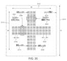
例示的な光学要素のいくつかの実施形態については、複数の光放射要素のうちの少なくとも一部は、プラス形状パターン(plus-shaped pattern)に構成することができる。For some embodiments of the exemplary optical element, at least some of the plurality of light emitting elements can be configured in a plus-shaped pattern.
例示的な光学要素のいくつかの実施形態については、装置の回転に応答して、方向制御可能なディフューザは、回転された方向において拡散することを可能にされることができ、装置は、ディスプレイの向きが縦から横に変化した場合、単一のビューだけが拡散の方向において生成されるように構成することができる。For some embodiments of the exemplary optical element, in response to rotation of the device, the orientation-controllable diffuser can be enabled to diffuse in the rotated direction, and the device can be configured such that when the display orientation is changed from portrait to landscape, only a single view is generated in the direction of diffusion.
例示的な装置のいくつかの実施形態は、3次元(3D)ディスプレイをさらに含むことができ、前記ディフューザの前記方向制御可能性は、3Dディスプレイにわたってパターン化することができ、空間的に変化する拡散方向特性を可能にする。Some embodiments of the exemplary device may further include a three-dimensional (3D) display, and the directional controllability of the diffuser may be patterned across the 3D display, allowing for spatially varying diffusion directional characteristics.
いくつかの実施形態に従った例示的な方法は、1つまたは複数の光放射デバイスから光ビームを放射するステップと、光ビームを直線偏光ビームに偏光するステップと、光ビームに液晶(LC)材料を通過させるステップと、光ビームに複屈折材料を通過させるステップと、電圧をLC材料に印加して、LC材料の光偏光構成状態を変更するステップとを含むことができ、光偏光構成状態を変更することは、第1の偏光状態から第2の偏光状態への切り替えを行い、第1の偏光状態は、複屈折材料を通過する際に、第1の方向において光ビームを拡散させ、第2の偏光状態は、複屈折材料を通過する際に、第2の方向において光ビームを拡散させる。An exemplary method according to some embodiments may include emitting a light beam from one or more light emitting devices, polarizing the light beam into a linearly polarized beam, passing the light beam through a liquid crystal (LC) material, passing the light beam through a birefringent material, and applying a voltage to the LC material to change the light polarization configuration state of the LC material, where changing the light polarization configuration state switches from a first polarization state to a second polarization state, where the first polarization state spreads the light beam in a first direction as it passes through the birefringent material, and the second polarization state spreads the light beam in a second direction as it passes through the birefringent material.
例示的な方法のいくつかの実施形態は、ライトフィールド(LF)ディスプレイデバイスのための1つまたは複数の像をレンダリングするステップと、1つまたは複数のレンダリングされた像をLFディスプレイデバイスに送るステップとをさらに含むことができる。Some embodiments of the example method may further include rendering one or more images for a light field (LF) display device and sending the one or more rendered images to the LF display device.
例示的な方法のいくつかの実施形態は、LFディスプレイデバイスのための視野(FOV)選択を受け取るステップをさらに含むことができる。Some embodiments of the example method may further include receiving a field of view (FOV) selection for the LF display device.
例示的な方法のいくつかの実施形態は、FOV選択に基づいて、放射される光ビームの明るさを調整するステップをさらに含むことができる。Some embodiments of the example method may further include adjusting the brightness of the emitted light beam based on the FOV selection.
いくつかの実施形態に従った例示的な装置は、光放射デバイスのアレイと、偏光子層と、マイクロレンズアレイ(MLA)と、1つまたは複数のディフューザと、1つまたは複数の回折格子とを含むことができる。An exemplary apparatus according to some embodiments can include an array of light emitting devices, a polarizer layer, a microlens array (MLA), one or more diffusers, and one or more diffraction gratings.
例示的な装置のいくつかの実施形態については、光放射デバイスのアレイは、光放射デバイスの1つまたは複数のセットを含むことができる。For some embodiments of the exemplary apparatus, the array of light-emitting devices can include one or more sets of light-emitting devices.
例示的な装置のいくつかの実施形態については、光放射デバイスの1つまたは複数のセットの各々は、ピクセルを含むことができる。For some embodiments of the exemplary apparatus, each of the one or more sets of light-emitting devices can include a pixel.
例示的方法のいくつかの実施形態は、バックボードと、1つまたは複数のバッフルとをさらに含むことができ、光放射デバイスの1つまたは複数のセットからなるアレイは、バックボードに取り付けられ、アレイのうちの光放射デバイスの各セットは、それぞれのバッフルに対応し、各バッフルは、光放射デバイスのそれぞれのセットを、光放射デバイスの1つまたは複数のセットからなるアレイのうちの残りから少なくとも部分的に分離する。Some embodiments of the exemplary method may further include a backboard and one or more baffles, where the array of one or more sets of light-emitting devices is mounted to the backboard, each set of light-emitting devices in the array corresponding to a respective baffle, each baffle at least partially separating each set of light-emitting devices from the remainder of the array of one or more sets of light-emitting devices.
例示的な装置のいくつかの実施形態については、1つまたは複数のディフューザのうちの少なくとも1つは、光放射デバイスのうちの少なくとも1つによって放射された光を水平方向において拡散するように構成することができ、1つまたは複数のディフューザのうちの少なくとも1つは、光放射デバイスのうちの少なくとも1つによって放射された光を垂直方向において拡散するように構成することができる。For some embodiments of the exemplary apparatus, at least one of the one or more diffusers can be configured to diffuse light emitted by at least one of the light-emitting devices in a horizontal direction, and at least one of the one or more diffusers can be configured to diffuse light emitted by at least one of the light-emitting devices in a vertical direction.
例示的な装置のいくつかの実施形態については、1つまたは複数のディフューザのうちの少なくとも1つは、光放射デバイスのうちの少なくとも1つによって放射された光を水平方向において拡散することと、垂直方向において拡散することとの間で切り替えを行うように構成することができる。For some embodiments of the exemplary apparatus, at least one of the one or more diffusers can be configured to switch between diffusing light emitted by at least one of the light-emitting devices in a horizontal direction and diffusing light in a vertical direction.
例示的な装置のいくつかの実施形態については、1つまたは複数のディフューザのうちの少なくとも1つは、表面効果液晶(SELC)ディフューザであることができる。For some embodiments of the exemplary device, at least one of the one or more diffusers can be a surface effect liquid crystal (SELC) diffuser.
例示的な装置のいくつかの実施形態については、SELCディフューザは、第1の基板と第2の基板との間に挟まれた、液晶(LC)材料層を含むことができ、LC材料層は、第1の基板および第2の基板と連携して、印加された電圧に応答して、光の角度選択的拡散を引き起こすように構成することができる。For some embodiments of the exemplary device, the SELC diffuser can include a liquid crystal (LC) material layer sandwiched between a first substrate and a second substrate, and the LC material layer can be configured to cooperate with the first substrate and the second substrate to cause angle-selective diffusion of light in response to an applied voltage.
例示的な装置のいくつかの実施形態については、SELCディフューザは、第1の基板と第2の基板との間に挟まれた、液晶(LC)材料層を含むことができ、LC材料層ならびに第1の基板および第2の基板は、光ビームを散乱するために連携して働く、選択された材料特性および境界面特性を有することができる。For some embodiments of the exemplary device, the SELC diffuser can include a liquid crystal (LC) material layer sandwiched between a first substrate and a second substrate, where the LC material layer and the first and second substrates can have selected material and interface properties that work in conjunction to scatter the light beam.
例示的な装置のいくつかの実施形態については、ディフューザのうちの少なくとも1つは、2D表示モードと3D表示モードとの間で切り替えを行うよう構成することができる。For some embodiments of the exemplary device, at least one of the diffusers can be configured to switch between a 2D display mode and a 3D display mode.
例示的装置のいくつかの実施形態については、ディフューザのうちの第1のSELCディフューザは、第1の像を表示する光を、第1の拡散方向を用いて散乱するように構成された、SELCディフューザであることができ、ディフューザのうちの第2のSELCディフューザは、第2の像を表示する光を、第2の拡散方向を用いて散乱するように構成された、SELCディフューザであることができ、第1の拡散方向は、第2の拡散方向と直交することができる。For some embodiments of the exemplary device, a first one of the diffusers can be a SELC diffuser configured to scatter light displaying a first image with a first diffusion direction, and a second one of the diffusers can be a SELC diffuser configured to scatter light displaying a second image with a second diffusion direction, and the first diffusion direction can be orthogonal to the second diffusion direction.
例示的な装置のいくつかの実施形態については、ディフューザのうちの少なくとも1つは、光放射デバイスのアレイによって投影される像についてのグレアを低減するために、光を拡散するように構成された、SELCディフューザであることができる。For some embodiments of the exemplary apparatus, at least one of the diffusers can be a SELC diffuser configured to diffuse light to reduce glare for an image projected by the array of light emitting devices.
例示的な装置のいくつかの実施形態については、回折格子のうちの少なくとも1つは、液晶材料を含むことができる。For some embodiments of the exemplary device, at least one of the diffraction gratings can include a liquid crystal material.
例示的な装置のいくつかの実施形態については、回折格子のうちの少なくとも1つは、複屈折材料を含むことができる。For some embodiments of the exemplary device, at least one of the diffraction gratings can include a birefringent material.
例示的な装置のいくつかの実施形態については、1つまたは複数のディフューザのうちの少なくとも1つは、光放射デバイスのうちの1つまたは複数によって放射された1つまたは複数の近隣光ビームを一緒に拡散するように、モザイクディフューザとして、構成することができる。For some embodiments of the exemplary apparatus, at least one of the one or more diffusers can be configured as a mosaic diffuser to diffuse together one or more neighboring light beams emitted by one or more of the light emitting devices.
様々な図に描かれ、様々な図との関連において説明される、エンティティ、接続、および配置などは、例として提示されており、限定として提示されていない。そのため、特定の図が「描いている」もの、特定の図内の特定の要素またはエンティティが何で「ある」か、または何を「有する」かに関する、ありとあらゆる言明または他の指摘、および孤立して文脈から切り離されて、絶対的なものとして、したがって、限定的なものとして読むことができる、ありとあらゆる類似の言明は、「少なくとも一実施形態においては、...」などの句が建設的に先行するものとしてのみ適切に読むことができる。提示の簡潔さおよび明瞭さのために、この暗示される先行句は、詳細な説明においてしつこく繰り返されることはない。The entities, connections, and arrangements, etc. depicted in and described in relation to the various figures are presented by way of example and not limitation. As such, any and all statements or other indications regarding what a particular figure "depicts" or what a particular element or entity in a particular figure "is" or "has," and any and all similar statements that, in isolation and out of context, may be read as absolute and therefore limiting, may only be properly read as constructively preceded by a phrase such as "In at least one embodiment, . . . " For brevity and clarity of presentation, this implied precedent phrase will not be persistently repeated in the Detailed Description.
例えば、本明細書において説明されるいくつかの実施形態におけるライトフィールドディスプレイデバイスとして、無線送受信ユニット(WTRU)を使用することができる。For example, a wireless transmit/receive unit (WTRU) may be used as the light field display device in some embodiments described herein.
図1Aは、1つまたは複数の開示される実施形態をその中で実施することができる、例示的な通信システム100を例示する図である。通信システム100は、音声、データ、ビデオ、メッセージング、放送などのコンテンツを複数の無線ユーザに提供する、多元接続システムであることができる。通信システム100は、複数の無線ユーザが、無線帯域幅を含むシステムリソースの共用を通し、そのようなコンテンツにアクセスすることを可能できる。例えば、通信システム100は、符号分割多元接続(CDMA)、時分割多元接続(TDMA)、周波数分割多元接続(FDMA)、直交FDMA(OFDMA)、シングルキャリアFDMA(SC-FDMA)、ゼロテールユニークワードDFT拡散OFDM(ZT UW DTS-s OFDM)、ユニークワードOFDM(UW-OFDM)、リソースブロックフィルタードOFDMおよびフィルタバンクマルチキャリア(FBMC)など、1つまたは複数のチャネルアクセス方法を利用することができる。1A is a diagram illustrating an
図1Aに示されるように、通信システム100は、無線送受信ユニット(WTRU)102a、102b、102c、102dと、RAN104/113と、CN106/115と、公衆交換電話網(PSTN)108と、インターネット110と、他のネットワーク112とを含むことができるが、開示される実施形態は、任意の数のWTRU、基地局、ネットワーク、および/またはネットワーク要素を企図していることが理解されよう。WTRU102a、102b、102c、102dの各々は、無線環境において動作および/または通信するように構成された任意のタイプのデバイスであることができる。例として、それのどれもが、「局」および/または「STA」と呼ばれることがある、WTRU102a、102b、102c、102dは、無線信号を送信および/または受信するように構成することができ、ユーザ機器(UE)、移動局、固定または移動加入者ユニット、サブスクリクションベースのユニット、ページャ、セルラ電話、パーソナルデジタルアシスタント(PDA)、スマートフォン、ラップトップ、ネットブック、パーソナルコンピュータ、無線センサ、ホットスポットまたはMi-Fiデバイス、モノのインターネット(IoT)デバイス、ウォッチまたは他のウェアラブル、ヘッドマウントディスプレイ(HMD)、乗物、ドローン、医療用デバイスおよびアプリケーション(例えば、遠隔手術)、工業用デバイスおよびアプリケーション(例えば、工業用および/または自動化された処理チェーン状況において動作するロボットおよび/または他の無線デバイス)、家電デバイス、ならびに商業用および/または工業用無線ネットワーク上において動作するデバイスなどを含むことができる。WTRU102a、102b、102c、102dのいずれも、交換可能に、UEと呼ばれることがある。As shown in FIG. 1A, the
通信システム100は、基地局114aおよび/または基地局114bも含むことができる。基地局114a、114bの各々は、CN106/115、インターネット110、および/または他のネットワーク112など、1つまたは複数の通信ネットワークへのアクセスを容易にするために、WTRU102a、102b、102c、102dのうちの少なくとも1つと無線でインターフェースをとるように構成された任意のタイプのデバイスであることができる。例として、基地局114a、114bは、基地送受信機局(BTS)、ノードB、eノードB、ホームノードB、ホームeノードB、gNB、ニューラジオ(NR)ノードB、サイトコントローラ、アクセスポイント(AP)、および無線ルータなどであることができる。基地局114a、114bは、各々が、単一の要素として描かれているが、基地局114a、114bは、任意の数の相互接続された基地局および/またはネットワーク要素を含むことができることが理解されよう。The
基地局114aは、RAN104/113の一部であることができ、RAN104/113は、他の基地局、および/または基地局コントローラ(BSC)、無線ネットワークコントローラ(RNC)、中継ノードなどのネットワーク要素(図示せず)も含むことができる。基地局114aおよび/または基地局114bは、セル(図示せず)と呼ばれることがある、1つまたは複数のキャリア周波数上において、無線信号を送信および/または受信するように構成することができる。これらの周波数は、免許要スペクトル、免許不要スペクトル、または免許要スペクトルと免許不要スペクトルとの組み合わせの中にあることができる。セルは、相対的に一定であることができる、または時間とともに変化することができる特定の地理的エリアに、無線サービス用のカバレージを提供することができる。セルは、さらに、セルセクタに分割することができる。例えば、基地局114aと関連付けられたセルは、3つのセクタに分割することができる。したがって、一実施形態においては、基地局114aは、送受信機を3つ、例えば、セルの各セクタに対して1つずつ含むことができる。実施形態においては、基地局114aは、多入力多出力(MIMO)技術を利用することができ、セルの各セクタに対して複数の送受信機を利用することができる。例えば、所望の空間方向において信号を送信および/または受信するために、ビームフォーミングを使用することができる。The
基地局114a、114bは、エアインターフェース116上において、WTRU102a、102b、102c、102dのうちの1つまたは複数と通信することができ、エアインターフェース116は、任意の適切な無線通信リンク(例えば、無線周波(RF)、マイクロ波、センチメートル波、マイクロメートル波、赤外線(IR)、紫外線(UV)、可視光など)であることができる。エアインターフェース116は、任意の適切な無線アクセス技術(RAT)を使用して、確立することができる。The
より具体的には、上で言及されたように、通信システム100は、多元接続システムであることができ、CDMA、TDMA、FDMA、OFDMA、およびSC-FDMAなど、1つまたは複数のチャネルアクセス方式を利用することができる。例えば、RAN104/113内の基地局114aと、WTRU102a、102b、102cは、広帯域CDMA(WCDMA)を使用して、エアインターフェース116を確立することができる、ユニバーサル移動体通信システム(UMTS)地上無線アクセス(UTRA)などの無線技術を実施することができる。WCDMAは、高速パケットアクセス(HSPA)および/または進化型HSPA(HSPA+)などの通信プロトコルを含むことができる。HSPAは、高速ダウンリンク(DL)パケットアクセス(HSDPA)、および/または高速ULパケットアクセス(HSUPA)を含むことができる。More specifically, as mentioned above, the
実施形態においては、基地局114aと、WTRU102a、102b、102cは、ロングタームエボリューション(LTE)、および/またはLTEアドバンスト(LTE-A)、および/またはLTEアドバンストプロ(LTE-A Pro)を使用して、エアインターフェース116を確立することができる、進化型UMTS地上無線アクセス(E-UTRA)などの無線技術を実施することができる。In an embodiment, the
実施形態においては、基地局114aと、WTRU102a、102b、102cは、ニューラジオ(NR)を使用して、エアインターフェース116を確立することができる、NR無線アクセスなどの無線技術を実施することができる。In an embodiment, the
実施形態においては、基地局114aと、WTRU102a、102b、102cは、複数の無線アクセス技術を実施することができる。例えば、基地局114aと、WTRU102a、102b、102cは、例えば、デュアルコネクティビティ(DC)原理を使用して、LTE無線アクセスと、NR無線アクセスとを一緒に実施することができる。したがって、WTRU102a、102b、102cによって利用されるエアインターフェースは、複数のタイプの無線アクセス技術、ならびに/または複数のタイプの基地局(例えば、eNBおよびgNB)に/から送信される送信によって特徴付けることができる。In an embodiment, the
他の実施形態においては、基地局114aと、WTRU102a、102b、102cは、IEEE802.11(例えば、ワイヤレスフィデリティ(WiFi))、IEEE802.16(例えば、マイクロ波アクセス用世界的相互運用性(WiMAX))、CDMA2000、CDMA2000 1X、CDMA2000 EV-DO、暫定標準2000(IS-2000)、暫定標準95(IS-95)、暫定標準856(IS-856)、移動体通信用グローバルシステム(GSM)、GSMエボリューション用高速データレート(EDGE)、およびGSM EDGE(GERAN)などの無線技術を実施することができる。In other embodiments, the
図1Aにおける基地局114bは、例えば、無線ルータ、ホームノードB、ホームeノードB、またはアクセスポイントであることができ、事業所、自宅、乗物、キャンパス、産業用施設、(例えば、ドローンによって使用される)エアコリド、および車道など、局所化されたエリアにおける無線接続性を容易にするために、任意の適切なRATを利用することができる。一実施形態においては、基地局114bと、WTRU102c、102dは、IEEE802.11などの無線技術を実施して、無線ローカルエリアネットワーク(WLAN)を確立することができる。実施形態においては、基地局114bと、WTRU102c、102dは、IEEE802.15などの無線技術を実施して、無線パーソナルエリアネットワーク(WPAN)を確立することができる。また別の実施形態においては、基地局114bと、WTRU102c、102dは、セルラベースのRAT(例えば、WCDMA、CDMA2000、GSM、LTE、LTE-A、LTE-A Pro、NRなど)を利用して、ピコセルまたはフェムトセルを確立することができる。図1Aに示されるように、基地局114bは、インターネット110への直接的な接続を有することができる。したがって、基地局114bは、CN106を介してインターネット110にアクセスする必要がないことがある。1A may be, for example, a wireless router, a Home NodeB, a Home eNodeB, or an access point, and may utilize any suitable RAT to facilitate wireless connectivity in a localized area, such as an office, a home, a vehicle, a campus, an industrial facility, an air corridor (e.g., used by drones), and a roadway. In one embodiment, the
RAN104/113は、CN106と通信することができ、CN106は、音声、データ、アプリケーション、および/またはボイスオーバインターネットプロトコル(VoIP)サービスを、WTRU102a、102b、102c、102dのうちの1つまたは複数に提供するように構成された任意のタイプのネットワークであることができる。データは、異なるスループット要件、遅延要件、エラー耐性要件、信頼性要件、データスループット要件、およびモビリティ要件など、様々なサービス品質(QoS)要件を有することができる。CN106は、呼制御、ビリングサービス、モバイルロケーションベースのサービス、プリペイド発呼、インターネット接続性、ビデオ配信などを提供することができ、および/またはユーザ認証など、高レベルセキュリティ機能を実行することができる。図1Aには示されていないが、RAN104/113および/またはCN106は、RAN104/113と同じRATまたは異なるRATを利用する他のRANと直接的または間接的通信を行うことができることが理解されよう。例えば、NR無線技術を利用していることがあるRAN104/113に接続されていることに加えて、CN106は、GSM、UMTS、CDMA2000、WiMAX、E-UTRA、またはWiFi無線技術を利用する別のRAN(図示せず)とも通信することができる。
CN106は、WTRU102a、102b、102c、102dが、PSTN108、インターネット110、および/または他のネットワーク112にアクセスするためのゲートウェイとしての役割も果たすことができる。PSTN108は、基本電話サービス(POTS)を提供する、回線交換電話網を含むことができる。インターネット110は、TCP/IPインターネットプロトコルスイート内の伝送制御プロトコル(TCP)、ユーザデータグラムプロトコル(UDP)、および/またはインターネットプロトコル(IP)など、共通の通信プロトコルを使用する、相互接続されたコンピュータネットワークおよびデバイスからなる地球規模のシステムを含むことができる。ネットワーク112は、他のサービスプロバイダによって所有および/または運営される、有線および/または無線通信ネットワークを含むことができる。例えば、ネットワーク112は、RAN104/113と同じRATまたは異なるRATを利用することができる1つまたは複数のRANに接続された、別のCNを含むことができる。The
通信システム100内のWTRU102a、102b、102c、102dのうちのいくつかまたはすべては、マルチモード機能を含むことができる(例えば、WTRU102a、102b、102c、102dは、異なる無線リンク上において、異なる無線ネットワークと通信するための、複数の送受信機を含むことができる)。例えば、図1Aに示されるWTRU102cは、セルラベースの無線技術を利用することができる基地局114aと通信するように、またIEEE802無線技術を利用することができる基地局114bと通信するように構成することができる。Some or all of the
図1Bは、例示的なWTRU102を例示するシステム図である。図1Bに示されるように、WTRU102は、とりわけ、プロセッサ118、送受信機120、送信/受信要素122、スピーカ/マイクロフォン124、キーパッド126、ディスプレイ/タッチパッド128、非リムーバブルメモリ130、リムーバブルメモリ132、電源134、全地球測位システム(GPS)チップセット136、および/または他の周辺機器138を含むことができる。WTRU102は、実施形態との整合性を保ちながら、上記の要素の任意のサブコンビネーションを含むことができることが理解されよう。1B is a system diagram illustrating an
プロセッサ118は、汎用プロセッサ、専用プロセッサ、従来型プロセッサ、デジタル信号プロセッサ(DSP)、複数のマイクロプロセッサ、DSPコアと連携する1つまたは複数のマイクロプロセッサ、コントローラ、マイクロコントローラ、特定用途向け集積回路(ASIC)、フィールドプログラマブルゲートアレイ(FPGA)回路、他の任意のタイプの集積回路(IC)、および状態機械などであることができる。プロセッサ118は、信号符号化、データ処理、電力制御、入力/出力処理、および/またはWTRU102が無線環境において動作することを可能にする他の任意の機能性を実行することができる。プロセッサ118は、送受信機120に結合することができ、送受信機120は、送信/受信要素122に結合することができる。図1Bは、プロセッサ118と送受信機120を別個の構成要素として描いているが、プロセッサ118と送受信機120は、電子パッケージまたはチップ内に一緒に統合することができることが理解されよう。The
送信/受信要素122は、エアインターフェース116上において、基地局(例えば、基地局114a)に信号を送信し、または基地局から信号を受信するように構成することができる。例えば、一実施形態においては、送信/受信要素122は、RF信号を送信および/または受信するように構成されたアンテナであることができる。実施形態においては、送信/受信要素122は、例えば、IR、UV、または可視光信号を送信および/または受信するように構成された放射器/検出器であることができる。また別の実施形態においては、送信/受信要素122は、RF信号および光信号の両方を送信および/または受信するように構成することができる。送信/受信要素122は、無線信号の任意の組み合わせを送信および/または受信するように構成することができることが理解されよう。The transmit/receive
図1Bにおいては、送信/受信要素122は、単一の要素として描かれているが、WTRU102は、任意の数の送信/受信要素122を含むことができる。より具体的には、WTRU102は、MIMO技術を利用することができる。したがって、一実施形態においては、WTRU102は、エアインターフェース116上において無線信号を送信および受信するための2つ以上の送信/受信要素122(例えば、複数のアンテナ)を含むことができる。Although the transmit/receive
送受信機120は、送信/受信要素122によって送信されることになる信号を変調し、送信/受信要素122によって受信された信号を復調するように構成することができる。上で言及されたように、WTRU102は、マルチモード機能を有することができる。したがって、送受信機120は、WTRU102が、例えば、NRおよびIEEE802.11など、複数のRATを介して通信することを可能にするための、複数の送受信機を含むことができる。The
WTRU102のプロセッサ118は、スピーカ/マイクロフォン124、キーパッド126、および/またはディスプレイ/タッチパッド128(例えば、液晶表示(LCD)ディスプレイユニットもしくは有機発光ダイオード(OLED)ディスプレイユニット)に結合することができ、それらからユーザ入力データを受信することができる。プロセッサ118は、スピーカ/マイクロフォン124、キーパッド126、および/またはディスプレイ/タッチパッド128にユーザデータを出力することもできる。加えて、プロセッサ118は、非リムーバブルメモリ130および/またはリムーバブルメモリ132など、任意のタイプの適切なメモリから情報を入手することができ、それらにデータを記憶することができる。非リムーバブルメモリ130は、ランダムアクセスメモリ(RAM)、リードオンリメモリ(ROM)、ハードディスク、または他の任意のタイプのメモリ記憶デバイスを含むことができる。リムーバブルメモリ132は、加入者識別モジュール(SIM)カード、メモリスティック、およびセキュアデジタル(SD)メモリカードなどを含むことができる。他の実施形態においては、プロセッサ118は、サーバまたはホームコンピュータ(図示せず)上など、WTRU102上に物理的に配置されていないメモリから情報を入手することができ、それらにデータを記憶することができる。The
プロセッサ118は、電源134から電力を受け取ることができ、WTRU102内の他の構成要素に電力を分配するように、および/またはそれらへの電力を制御するように構成することができる。電源134は、WTRU102に給電するための任意の適切なデバイスであることができる。例えば、電源134は、1つまたは複数の乾電池(例えば、ニッケル-カドミウム(NiCd)、ニッケル-亜鉛(NiZn)、ニッケル水素(NiMH)、リチウム-イオン(Li-ion)など)、太陽電池、および燃料電池などを含むことができる。The
プロセッサ118は、GPSチップセット136にも結合することができ、GPSチップセット136は、WTRU102の現在ロケーションに関するロケーション情報(例えば、経度および緯度)を提供するように構成することができる。GPSチップセット136からの情報に加えて、またはそれの代わりに、WTRU102は、基地局(例えば、基地局114a、114b)からエアインターフェース116上においてロケーション情報を受信することができ、および/または2つ以上の近くの基地局から受信している信号のタイミングに基づいて、自らのロケーションを決定することができる。WTRU102は、実施形態との整合性を保ちながら、任意の適切なロケーション決定方法を用いて、ロケーション情報を獲得することができることが理解されよう。The
プロセッサ118は、さらに他の周辺機器138に結合することができ、他の周辺機器138は、追加の特徴、機能性、および/または有線もしくは無線接続性を提供する、1つまたは複数のソフトウェアモジュールおよび/またはハードウェアモジュールを含むことができる。例えば、周辺機器138は、加速度計、eコンパス、衛星送受信機、(写真および/またはビデオ用の)デジタルカメラ、ユニバーサルシリアルバス(USB)ポート、バイブレーションデバイス、テレビ送受信機、ハンズフリーヘッドセット、Bluetooth(登録商標)モジュール、周波数変調(FM)ラジオユニット、デジタル音楽プレーヤ、メディアプレーヤ、ビデオゲームプレーヤモジュール、インターネットブラウザ、仮想現実および/または拡張現実(VR/AR)デバイス、ならびにアクティビティトラッカなどを含むことができる。周辺機器138は、1つまたは複数のセンサを含むことができ、センサは、ジャイロスコープ、加速度計、ホール効果センサ、磁力計、方位センサ、近接センサ、温度センサ、時間センサ、ジオロケーションセンサ、高度計、光センサ、タッチセンサ、気圧計、ジェスチャセンサ、バイオメトリックセンサ、および/または湿度センサのうちの1つまたは複数であることができる。The
WTRU102は、(例えば、(例えば、送信用の)ULと(例えば、受信用の)ダウンリンクの両方のための特定のサブフレームと関連付けられた)信号のいくつかまたはすべての送信および受信が、並列および/または同時であることができる、全二重無線を含むことができる。全二重無線は、ハードウェア(例えば、チョーク)、またはプロセッサ(例えば、別個のプロセッサ(図示せず)もしくはプロセッサ118)を介する信号処理のいずれかを介して、自己干渉を低減させ、および/または実質的に除去するために、干渉管理ユニット139を含むことができる。実施形態においては、WTRU102は、(例えば、(例えば、送信用の)ULまたは(例えば、受信用の)ダウンリンクのどちらかのための特定のサブフレームと関連付けられた)信号のいくつかまたはすべての送信および受信のための、半二重無線を含むことができる。The
図1A~図1B、および図1A~図1Bについての対応する説明に鑑みて、WTRU102a~d、基地局114a~b、および/または本明細書において説明される他の任意のデバイスのうちの1つまたは複数に関する、本明細書において説明される機能の1つもしくは複数またはすべては、1つまたは複数のエミュレーションデバイス(図示せず)によって実行することができる。エミュレーションデバイスは、本明細書において説明される機能の1つもしくは複数またはすべてをエミュレートするように構成された、1つまたは複数のデバイスであることができる。例えば、エミュレーションデバイスは、他のデバイスをテストするために、ならびに/またはネットワークおよび/もしくはWTRU機能をシミュレートするために、使用することができる。In view of FIGS. 1A-1B and the corresponding description thereof, one or more or all of the functions described herein with respect to one or more of the
エミュレーションデバイスは、実験室環境において、および/またはオペレータネットワーク環境において、他のデバイスの1つまたは複数のテストを実施するように設計することができる。例えば、1つまたは複数のエミュレーションデバイスは、通信ネットワーク内の他のデバイスをテストするために、有線および/または無線通信ネットワークの一部として、完全または部分的に実施および/または展開されながら、1つもしくは複数またはすべての機能を実行することができる。1つまたは複数のエミュレーションデバイスは、有線および/または無線通信ネットワークの一部として、一時的に実施/展開されながら、1つもしくは複数またはすべての機能を実行することができる。エミュレーションデバイスは、テストを行う目的で、別のデバイスに直接的に結合することができ、および/またはオーバザエア無線通信を使用してテストを実行することができる。The emulation device can be designed to perform one or more tests of other devices in a laboratory environment and/or in an operator network environment. For example, one or more emulation devices can perform one or more or all functions while fully or partially implemented and/or deployed as part of a wired and/or wireless communication network to test other devices in the communication network. One or more emulation devices can perform one or more or all functions while temporarily implemented/deployed as part of a wired and/or wireless communication network. The emulation device can be directly coupled to another device for testing purposes and/or can perform the tests using over-the-air wireless communication.
1つまたは複数のエミュレーションデバイスは、有線および/または無線通信ネットワークの一部として実施/展開されずに、すべての機能を含む1つまたは複数の機能を実行することができる。例えば、エミュレーションデバイスは、1つまたは複数の構成要素のテストを実施するために、テスト実験室ならびに/または展開されていない(例えば、テスト)有線および/もしくは無線通信ネットワークにおける、テストシナリオにおいて利用することができる。1つまたは複数のエミュレーションデバイスは、テスト機器であることができる。データを送信および/または受信するために、直接RF結合、および/または(例えば、1つもしくは複数のアンテナを含むことができる)RF回路を介した無線通信を、エミュレーションデバイスによって使用することができる。The one or more emulation devices may perform one or more functions, including all functions, without being implemented/deployed as part of a wired and/or wireless communication network. For example, the emulation devices may be utilized in a test lab and/or in a test scenario in a non-deployed (e.g., test) wired and/or wireless communication network to perform testing of one or more components. The one or more emulation devices may be test equipment. Direct RF coupling and/or wireless communication via RF circuitry (which may include, e.g., one or more antennas) may be used by the emulation devices to transmit and/or receive data.
多くの以前の3Dディスプレイは、それらのフォームファクタに基づいて、4つの例示的なカテゴリ、すなわち、ヘッドマウントディスプレイ/デバイス(HMD)、ボリューム3Dディスプレイ、スクリーンベースの3Dディスプレイ、およびホログラフィックディスプレイに分類することができる。例示的なカテゴリは、説明のためのものにすぎず、例えば、いくつかのケースおよび例においては、重複することがある。Many previous 3D displays can be classified into four exemplary categories based on their form factor: head-mounted displays/devices (HMDs), volumetric 3D displays, screen-based 3D displays, and holographic displays. The exemplary categories are for illustration purposes only and may overlap in some cases and examples, for example.
多くのヘッドマウントデバイス(HMD)は、ゴーグルレスデバイスよりも少ないスペースを占め、より小さいコンポーネントおよびより少ない材料を用いて作成することができ、これは、相対的に低いコストに変換することができる。しかしながら、ヘッドマウントVRゴーグルおよびスマートグラスは、シングルユーザデバイスであるので、そのようなデバイスは、ゴーグルレスソリューションほど自然な共有体験を可能にしない。Many head-mounted devices (HMDs) take up less space and can be made with smaller components and less material than goggle-less devices, which can translate to relatively lower costs. However, because head-mounted VR goggles and smart glasses are single-user devices, such devices do not allow for as natural a shared experience as goggle-less solutions.
ボリューム3Dディスプレイは、3つの空間方向すべてからスペースを取り、多くの物理的な材料を必要とすることがあり、多くのそのようなデバイスを重く、製造が高価で、輸送が困難なものにする。材料を多用するせいで、ボリュームディスプレイは、小さい「窓」と、限られた視野(FOV)とを有する傾向もある。Volumetric 3D displays take up space from all three spatial directions and can require a lot of physical material, making many such devices heavy, expensive to manufacture, and difficult to transport. Due to their heavy use of material, volumetric displays also tend to have small "windows" and limited fields of view (FOV).
スクリーンベースの3Dディスプレイは、一般に、1つの大きいが平らなスクリーンと、遠方から自由空間上に像を投影するデバイスとを有する。これらのデバイスは、輸送のためによりコンパクトにすることができ、例えば、ボリュームディスプレイよりも大きいFOVを有することができる。これらのデバイスの多くは、複雑で高価であり、プロジェクタサブアセンブリを必要とする。多くのそのようなデバイスは、例えば、異なるパーツ間の正確なアライメントも必要とする。フラットなフォームファクタの3Dディスプレイは、2つの空間方向に多くのスペースを必要とすることがあるが、第3の方向は、仮想的なものにすぎないので、そのようなデバイスは、異なる環境への輸送および異なる環境における組み立てが相対的に容易であることがある。デバイスが、平らであるので、光学コンポーネントのいくつかは、シートまたはロール形式で製造することができ、大量であるときは、それらを相対的に低コストにする。Screen-based 3D displays generally have one large but flat screen and a device that projects an image onto free space from a distance. These devices can be more compact for transportation and can have a larger FOV than volumetric displays, for example. Many of these devices are complex and expensive, and require a projector subassembly. Many such devices also require, for example, precise alignment between different parts. Although flat form-factor 3D displays can require a lot of space in two spatial directions, such devices can be relatively easy to transport to and assemble in different environments, since the third direction is only virtual. Because the devices are flat, some of the optical components can be manufactured in sheet or roll format, making them relatively low cost when in large quantities.
正しい網膜焦点キューを提供することが可能な3Dディスプレイデバイスの別のタイプは、ホログラフィックディスプレイである。ホログラフィックディスプレイは、自然環境において物体から散乱された光波面全体を再構成することを目的とする。多くのそのようなデバイスは、極めて詳細な波面の生成に使用することができる、適切な空間光変調器(SLM)コンポーネントを欠いている。Another type of 3D display device capable of providing the correct retinal focal cues is the holographic display. Holographic displays aim to reconstruct the entire light wavefront scattered from an object in the natural environment. Many such devices lack a suitable spatial light modulator (SLM) component that can be used to generate a highly detailed wavefront.
自然な網膜焦点キューを提供することが可能な3Dディスプレイ技術のさらなるタイプは、ライトフィールド(LF)ディスプレイと呼ばれる。LFディスプレイシステムは、一般に、空間内をすべての方向に進む光線を表す、いわゆるライトフィールドを生成するように設計することができる。LFシステムは、一般に、空間領域および角度領域の両方において、高解像度で光の放射を制御することを目的とすることができる。非常に高い角解像度を有するマルチビュー3Dディスプレイも、LFディスプレイと呼ばれることがある。HMD、ボリューム3Dディスプレイ、およびスクリーンベースのディスプレイは、すべて、LFディスプレイのいくつかの例として含まれることがある。A further type of 3D display technology capable of providing natural retinal focal cues is called a light field (LF) display. LF display systems can generally be designed to generate a so-called light field, which represents light rays traveling in all directions in space. LF systems can generally aim to control the emission of light with high resolution, both in the spatial and angular domains. Multi-view 3D displays with very high angular resolution may also be called LF displays. HMDs, volumetric 3D displays, and screen-based displays may all be included as some examples of LF displays.
多くの相対的に低密度のマルチビューイメージングディスプレイにおいては、視聴者が、デバイスの前で移動するにつれて、ビューは、粗く段階的に変化する。この特性は、3D体験の質を低下させ、3D知覚の完全な崩壊を引き起こすことさえある。この問題を(適合的眼球離反運動の不一致(VAC)タイプの問題と一緒に)軽減するために、いくつかのスーパーマルチビュー(SMV)技法が、512個ものビューを用いてテストされた。2つの視点間のいかなる移行も非常に滑らかにするために、極めて多数のビューが、生成される。僅かに異なる視点からの少なくとも2つの像からの光が、同時に眼の瞳孔に入る場合、はるかによりリアリスティックな視覚体験が、生じる。このケースにおいては、脳が、運動に起因する像変化を無意識的に予測するので、運動視差効果は、自然な状態により良く似たものになる。SMV条件は、正しい視聴距離における2つのビューの間の間隔を、眼の瞳孔のサイズよりも小さい値に引き下げることによって、満たすことができる。通常の照明条件においては、人間の瞳孔は、一般に、直径約4mmであると推定される。周囲光レベルが、高い(例えば、日光の下にある)場合、直径は、1.5mm程度まで小さくなることがあり、暗い条件においては、8mm程度まで大きくなることがある。SMVディスプレイを用いて達成することができる最大角密度は、回折によって制限され、空間解像度(ピクセルサイズ)と角解像度との間には、反比例関係が、存在する。回折は、開口を通過する光ビームの角度広がりを増大させ、非常に高密度のSMVディスプレイの設計においては、この効果を計算に入れることがしばしば必要になることがある。In many relatively low-density multi-view imaging displays, the views change coarsely and stepwise as the viewer moves in front of the device. This characteristic can degrade the quality of the 3D experience and even cause a complete breakdown of 3D perception. To mitigate this problem (along with adaptive vergence discrepancy (VAC) type problems), several super-multiview (SMV) techniques have been tested with as many as 512 views. A very large number of views is generated to make any transition between two viewpoints very smooth. A much more realistic visual experience occurs when light from at least two images from slightly different viewpoints enters the pupil of the eye at the same time. In this case, the motion parallax effect resembles the natural situation more closely, since the brain unconsciously predicts the image changes due to motion. The SMV condition can be met by reducing the spacing between the two views at the correct viewing distance to a value smaller than the size of the eye's pupil. In normal lighting conditions, the human pupil is typically estimated to be about 4 mm in diameter. When ambient light levels are high (e.g., in sunlight), the diameter can be as small as 1.5 mm, and in dark conditions it can be as large as 8 mm. The maximum angular density that can be achieved with an SMV display is limited by diffraction, and there is an inverse relationship between spatial resolution (pixel size) and angular resolution. Diffraction increases the angular spread of a light beam passing through an aperture, and it can often be necessary to take this effect into account in the design of very high density SMV displays.
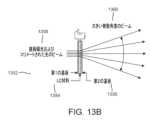
いくつかの実施形態については、角度選択的な光拡散が可能な、調整可能なディフューザコンポーネントは、パーツを動かさずに、光ビーム角度発散特性の変更を可能にする。そのようなディフューザは、光学境界面光散乱効果に基づいたコンポーネントを有することができる。特定の視野については、表面効果液晶(SELC)調整可能ディフューザを有する、3D光学ディスプレイ構造のいくつかの実施形態は、他のデバイスよりも少数の光放射コンポーネントを有することができる。いくつかの実施形態については、光は、別々に制御可能な小さいエミッタから放射され、マイクロレンズアレイを用いてコリメートされる。SELCは、視野方向の向きが切り替えられたときに、放射されたビームの選択的な拡散のために使用される。いくつかの実施形態については、そのようなディフューザは、他のデバイスよりも少量のエミッタを用いてより低コストで作成することができる。For some embodiments, an adjustable diffuser component capable of angle-selective light diffusion allows for the modification of light beam angular divergence characteristics without moving parts. Such diffusers can have components based on optical interface light scattering effects. For a particular field of view, some embodiments of 3D optical display structures with surface effect liquid crystal (SELC) adjustable diffusers can have fewer light emitting components than other devices. For some embodiments, light is emitted from small emitters that are separately controllable and collimated using a microlens array. The SELC is used for selective diffusion of the emitted beam when the viewing direction is switched. For some embodiments, such diffusers can be made at a lower cost with fewer emitters than other devices.
例えば、電源オン状態においては透過的で透明であり、例えば、電源オフ状態においては非透明であることができる、いわゆる「スマートウィンドウ」が、存在する。体積散乱ベースのLCディフューザは、透明ディスプレイまたはスマートグラスにおいて使用される、高分子安定化液晶(PSLC)または高分子分散型液晶(PDLC)などの、ディスプレイ技術において使用されてきた。従来の方法は、多くのケースにおいては、角度依存なしの、完全に透過的または光拡散的のどちらかであると理解される。There are so-called "smart windows" that can be transparent and clear in the power-on state and non-transparent in the power-off state. Volume scattering-based LC diffusers have been used in display technologies such as polymer stabilized liquid crystal (PSLC) or polymer dispersed liquid crystal (PDLC) for use in transparent displays or smart glasses. Conventional methods are understood in many cases to be either fully transparent or light diffusing, without angle dependence.
固定された角度性能を有する、例示的な静的光方向コントローラおよび静的光整形ディフューザが、存在する。拡散効果の角度制御を、ディスプレイとともに使用することができる。例えば、Luminitは、固定された角度性能を有する静的デバイスである、方向転換フィルム(DTF)および光整形ディフューザ(LSD)を生産してきたと理解されている。方向特性は、製造時に固定される。There are exemplary static light direction controllers and static light shaping diffusers that have fixed angular performance. Angular control of the diffusion effect can be used with displays. For example, Luminit is understood to have produced turning films (DTF) and light shaping diffusers (LSD) that are static devices with fixed angular performance. The directional characteristics are fixed at the time of manufacture.
図2は、いくつかの実施形態に従った、第1の構成における例示的なハンドセットディスプレイを示す図である。図2は、ハンドセットディスプレイと、3人の視聴者によって見られる像とを示している。全方向における広い拡散(例えば、180度)は、第1の電力レベルにおいて、像の全般的なマルチユーザ視聴のために使用することができる。FOV202は、例えば、180度であり、視聴者204、206、208のすべてが、像を見る。Figure 2 illustrates an exemplary handset display in a first configuration, according to some embodiments. Figure 2 shows the handset display and an image seen by three viewers. Wide diffusion in all directions (e.g., 180 degrees) can be used for general multi-user viewing of the image at a first power level. The
図3Aは、いくつかの実施形態に従った、第2の構成における例示的なハンドセットディスプレイを示す図である。図3Aは、FOV302が縮小するが(例えば、80度)、より明るい像を示しており、より明るい像は、単一の視聴者304だけによって見られる。いくつかの実施形態については、ハンドセットディスプレイは、制御可能なFOV縮小を使用して、FOV縮小と引き換えに電力を節約することができる。Figure 3A is a diagram illustrating an exemplary handset display in a second configuration, according to some embodiments. Figure 3A shows a brighter image, with a reduced FOV 302 (e.g., 80 degrees), where the brighter image is seen by only a
図3Bは、いくつかの実施形態に従った、第3の構成における例示的なハンドセットディスプレイを示す図である。図3Bは、FOV352が縮小するが(例えば、80度)、図3Aと比較してより低い明るさレベルを示している。図3Aにおけるように、図3Bにおける像は、ただ1人の視聴者354によって見られる。いくつかの実施形態については、適度なレベルの拡散を使用して、縮小された視野を提供し、FOV縮小に従って、放射される光を低減することによって、最重要の視聴者によって見られる明るさの低減なしに、電力節約を達成することができる。Figure 3B illustrates an exemplary handset display in a third configuration, according to some embodiments. Figure 3B shows a lower brightness level compared to Figure 3A, although the
マルチビューLFディスプレイは、空間多重化だけに基づくことができる。光放射ピクセル(ディスプレイサブピクセル)の行またはマトリックスを、レンチキュラレンズシートまたはマイクロレンズアレイの後ろに配置することができ、各ピクセルは、ディスプレイ構造の前の唯一のビュー方向またはビュー方向の限られたセットに投影することができる。各光ビームコリメーティング特徴の後ろの光放射層上のピクセルが、多いほど、生成することができるビューは、多い。この現象は、空間解像度と生成される固有のビューの数との間のトレードオフをもたらすことがある。3Dディスプレイが、より小さいLFピクセルサイズを生成する場合、個々のサブピクセルのサイズを低減させることができ、および/またはより少数の視聴方向を生成することができる。サブピクセルサイズは、適切なコンポーネントの欠如のせいで、相対的に大きい面積に制限されることがある。高品質のLFディスプレイは、高い空間解像度および角解像度の両方を有することができる。高い角解像度は、スーパーマルチビュー(SMV)条件を満たすために必要なことがあり、現在利用可能な源を用いて達成することが非常に困難なことがある。Multi-view LF displays can be based solely on spatial multiplexing. A row or matrix of light-emitting pixels (display subpixels) can be placed behind a lenticular lens sheet or microlens array, with each pixel projecting into only one viewing direction or a limited set of viewing directions in front of the display structure. The more pixels on the light-emitting layer behind each light beam collimating feature, the more views can be generated. This phenomenon can result in a trade-off between spatial resolution and the number of unique views generated. If a 3D display produces smaller LF pixel sizes, the size of the individual subpixels can be reduced and/or fewer viewing directions can be generated. Subpixel sizes can be limited to relatively large areas due to a lack of suitable components. High-quality LF displays can have both high spatial and angular resolution. High angular resolution may be required to meet super-multiview (SMV) conditions and can be very difficult to achieve with currently available sources.
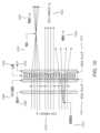
図4Aは、いくつかの実施形態に従った、第1の焦点長を有する例示的なマルチビュー3Dディスプレイ構造を示す図である。図4Bは、いくつかの実施形態に従った、第2の焦点長を有する例示的なマルチビュー3Dディスプレイ構造を示す図である。図4Cは、いくつかの実施形態に従った、第3の焦点長を有する例示的なマルチビュー3Dディスプレイ構造を示す図である。Figure 4A illustrates an exemplary multi-view 3D display structure having a first focal length, according to some embodiments. Figure 4B illustrates an exemplary multi-view 3D display structure having a second focal length, according to some embodiments. Figure 4C illustrates an exemplary multi-view 3D display structure having a third focal length, according to some embodiments.
光学設計問題の例として、図4Aおよび図4Bは、レンチキュラシートが、光エミッタアレイの前に配置された、2つの一体型イメージングマルチビューディスプレイのケースを示している。図4Aおよび図4Bの例においては、エミッタの量およびサイズは、同じである。レンチキュラレンズは、レンズ表面と源との間の距離である焦点長(FL)402、432が、同じになるように設計することができる。レンチキュラレンズの光学系は、マルチビュー像を異なるビュー方向に示す際に使用される、複数の良好にコリメートされた個々の光のビームを生成することができることがある。両方の例示的なケースは、同じ視野(FOV)406、436を有するが、図4Bの構造は、3つの示されたビュー408、410、412で3つの光源をカバーする、図4Aのレンズ開口404の代わりに、5つの示されたビュー438、440、442、444、446で5つの光源をカバーする、より大きいレンズ開口434を有するので、角解像度は、より高い。しかしながら、開口が、より大きいので、空間解像度は、より低い。As an example of the optical design problem, Figures 4A and 4B show the case of two integrated imaging multi-view displays in which a lenticular sheet is placed in front of a light emitter array. In the examples of Figures 4A and 4B, the amount and size of the emitters are the same. The lenticular lenses can be designed so that the focal length (FL) 402, 432, which is the distance between the lens surface and the source, is the same. The lenticular lens optics may be able to generate multiple well-collimated individual beams of light that are used in showing the multi-view image in different view directions. Both exemplary cases have the same field of view (FOV) 406, 436, but the structure of Figure 4B has a
角度ビュー密度と全角度範囲またはFOVとでも、同様のトレードオフが、生じることがある。マイクロレンズとエミッタとの間の距離を増加させ、それに応じて、マイクロレンズの屈折力を減少させることによって、角度ビュー密度は、増加させることができるが、FOVは、低下する。このトレードオフは、図4Bおよび図4Cに描かれたディスプレイ光学系のケースにおいて、例示されている。両方の構造は、同じレンズ開口サイズ464、434を有し、両方の構造は、各プロジェクタセルのために、5つの異なるビュービーム438、440、442、444、446、468、470、472、474、476を生成することができる。しかし、図4Cの構造の光学系は、より長いFL462を有するので、ビーム468、470、472、474、476は、より低いFOV466に投影され、角密度は、増加する。A similar tradeoff can occur between angular view density and total angular range or FOV. By increasing the distance between the microlens and the emitter and correspondingly decreasing the refractive power of the microlens, the angular view density can be increased but the FOV decreases. This tradeoff is illustrated in the case of the display optics depicted in Figures 4B and 4C. Both structures have the same
一体型イメージングベースのLFディスプレイは、複数の異なる像の生成において、複数のインターレースされたビームが一緒に使用される、空間領域および角度領域を有する。光学ディスプレイ構造を用いて、視野要件および像均一性要件を満たすために、光拡散面が、しばしば必要とされる。ディフューザ構造は、例えば、体積像の生成、単一像均一性を改善すること、FOVを増大させること、および/または近隣ビュー間の移行をより円滑にすることに利用することができる。材料散布または均一な面マイクロ構造を使用する、多くの光ディフューザと関連付けられた問題は、そのようなディフューザが、光をすべての方向に同様に拡散する傾向があることである。この特性は、(1)立体視効果の生成のために、1つの方向において高い角解像度を維持し、(2)より大きい視聴ウィンドウから像が見えるようにするために、他の方向において拡散を用いてFOVを増大させる場合、しばしば望ましくない特徴である。この特性を扱うために、いくつかのホログラフィック回折格子が、開発されているが、多くのそのような回折格子は、非常に特殊化された製造方法を必要とし、異なる用途に調整することが困難な、静的なコンポーネントである。本明細書において開示されるいくつかの実施形態については、調整可能なディフューザおよび/または調整可能なディフューザコンポーネントを、3Dディスプレイ構造において、使用することができる。An integrated imaging-based LF display has spatial and angular regions where multiple interlaced beams are used together in the generation of multiple different images. To meet the viewing and image uniformity requirements with an optical display structure, a light diffusing surface is often required. Diffuser structures can be used, for example, to generate volumetric images, improve single image uniformity, increase the FOV, and/or make the transition between neighboring views smoother. A problem associated with many light diffusers that use material scattering or uniform surface microstructures is that such diffusers tend to diffuse light similarly in all directions. This property is often an undesirable feature when (1) maintaining high angular resolution in one direction for the generation of a stereoscopic effect and (2) increasing the FOV with diffusion in other directions to make the image visible from a larger viewing window. To address this property, some holographic diffraction gratings have been developed, but many such diffraction gratings are static components that require highly specialized manufacturing methods and are difficult to tune for different applications. For some embodiments disclosed herein, adjustable diffusers and/or adjustable diffuser components can be used in 3D display structures.
ライトフィールドディスプレイとして分類される、多くの高品質マルチビューディスプレイは、空間領域および角度領域の両方において、(例えば、ユーザによって決定される)十分に良好な解像度を獲得するために、非常に多数の光源を必要とする。源は、像を異なる角度方向において投影する光学デバイスと関連付けられた光学効率差を補償するために、非常に高いダイナミックレンジを有することがしばしば必要とされる。特にディスプレイ用途に開発された多くのμLEDは、そのようなダイナミックレンジをしばしば有する。そのようなμLEDに伴う1つの課題は、マイクロスケールコンポーネントの極めて高密度な組み立てを求める要件であることがある。また、そのようなコンポーネントは、個別にアドレス指定可能である必要があるので、電気的接続を小さいスケール内に配置することが、非常に困難になる。コンポーネントの数は非常に多く、源モジュールの製造は極度の精度をしばしば必要とするので、この困難さは、高コストをしばしばもたらす。Many high-quality multi-view displays, classified as light field displays, require a very large number of light sources to obtain a sufficiently good resolution (e.g., as determined by the user) in both the spatial and angular domains. The sources are often required to have a very high dynamic range to compensate for the optical efficiency differences associated with optical devices that project images at different angular directions. Many μLEDs developed specifically for display applications often have such a dynamic range. One challenge with such μLEDs can be the requirement for extremely dense assembly of microscale components. Also, such components need to be individually addressable, making it very difficult to place electrical connections at a small scale. This difficulty often results in high costs, as the number of components is very large and the manufacture of source modules often requires extreme precision.
図5は、いくつかの実施形態に従った、ディスプレイの両側に像ゾーンを有する、例示的な3Dライトフィールドディスプレイを示す図である。3Dディスプレイと視聴者との間に、いかなる光散乱媒体も有さず、ディスプレイのすべてのエリアが、視聴者の両眼に向かってエミッタ像を投影する。しかしながら、一般に、立体視像を生成するためには、ディスプレイ内部の1つのエミッタが、両眼から同時に見えるべきではない。これは、ディスプレイのすべての部分からの放射ビーム束視野(FOV)は、両眼をカバーするが、単一ビームは、視聴距離において、それを2つの眼の瞳孔間の距離(平均で約64mm)よりも狭くする、FOVを有する必要があることを意味する。1つのディスプレイセクションのFOV、および単一エミッタのFOVは、エミッタ行/エミッタの幅と、結像光学系の倍率によって決定される。Figure 5 shows an exemplary 3D light field display with image zones on both sides of the display, according to some embodiments. There is no light scattering medium between the 3D display and the viewer, and all areas of the display project emitter images towards both eyes of the viewer. However, in general, to generate a stereoscopic image, one emitter inside the display should not be visible by both eyes at the same time. This means that the field of view (FOV) of the emitted beam flux from all parts of the display covers both eyes, but the single beam needs to have an FOV that makes it narrower than the distance between the pupils of the two eyes at the viewing distance (about 64 mm on average). The FOV of one display section, and therefore of a single emitter, is determined by the width of the emitter row/emitter and the magnification of the imaging optics.
ビーム束FOVを指定された視聴距離において重ね合わせるために、ディスプレイを、例えば、ある半径で湾曲させることができ、または投影されたビームを、例えば、平らなフレネルレンズシートを用いて、指定された点に向けて曲げることができる。エミッタおよびマイクロレンズに基づいた、単純なマルチビューディスプレイも、エミッタのロケーションがコリメーティングレンズの中心軸に対して僅かにずらされる技法を使用することができる。このずらしを、中心ディスプレイ位置からディスプレイ縁に向かって増加させた場合、ディスプレイ縁から投影されるビーム束を、中心ビーム束と重ね合わせることができる。FOVが、重なり合わない場合、3D像のいくつかの部分が、形成されないことがある。To make the beam bundle FOVs overlap at a specified viewing distance, the display can be curved, for example, with a radius, or the projected beams can be bent toward a specified point, for example, with a flat Fresnel lens sheet. Simple multi-view displays based on emitters and microlenses can also use techniques in which the location of the emitter is slightly offset with respect to the central axis of the collimating lens. If this offset is increased from the central display position toward the display edge, the beam bundles projected from the display edge can be overlapped with the central beam bundle. If the FOVs do not overlap, some parts of the 3D image may not be formed.
デバイスの制限されたサイズと、焦点距離についての実際的な限界のせいで、3D像が見える像ゾーンが、ディスプレイデバイスの前および/または後ろに形成される。図5は、3D LFディスプレイ構造を用いて達成することができる、例示的な視聴ジオメトリを示している。曲面ディスプレイの前に、合理的な空間解像度を有するディスプレイから最も遠い焦点距離によって、また全ディスプレイFOVによって制限される3D像ゾーンが、存在する。放射されたビームの仮想延長を用いて形成される別の像ゾーンも、ディスプレイの後ろに存在することができる。視聴者が、より遠く離れて位置付けられ、眼の解像度が、より低くなるので、ディスプレイの後ろでは、より大きいボクセルを許容することができる。最大像距離は、拡大ビーム仮想延長を用いて達成可能な最小許容解像度に基づいて、選択することができる。Due to the limited size of the device and practical limitations on focal length, image zones in which 3D images are visible are formed in front of and/or behind the display device. Figure 5 shows an example viewing geometry that can be achieved with a 3D LF display structure. In front of the curved display there is a 3D image zone limited by the farthest focal length from the display with reasonable spatial resolution and by the total display FOV. There can also be another image zone behind the display, formed using a virtual extension of the emitted beam. Larger voxels can be tolerated behind the display, since the viewer is positioned further away and the eye resolution is lower. The maximum image distance can be selected based on the minimum acceptable resolution achievable using an expanded beam virtual extension.
図5において、ディスプレイ面は、指定された視聴距離と同じ半径で湾曲させられる。重なり合うビーム束FOVは、視聴者514の顔エリアの周囲に、視聴ゾーン512を形成する。この視聴ゾーン512のサイズは、視聴者の頭部に対して許容される移動の量を決定することができる。視聴者514が立体視像を見るためには、両眼の瞳孔が、同時にゾーン512内にある必要がある。いくつかの実施形態については、視聴ゾーン512のサイズは、ビーム束FOVを変更することによって、調整することができる。ディスプレイ502は、ディスプレイ502の後方に後方像ゾーン504を、またディスプレイ502の前方に前方像ゾーン506を生成することができる。ディスプレイは、ディスプレイFOV508、および視聴者514についてのLFピクセルFOV510を生成することができる。各眼の間の平均瞳孔距離516は、64mmである。最小像距離518は、視聴者の目から前方像ゾーン506の前面の円弧の中心までの距離である。ディスプレイ視聴距離520は、視聴者の目からディスプレイ502の円弧の中心までの距離である。最大像距離522は、視聴者の目から後方像ゾーン504の後面の円弧の中心までの距離である。In FIG. 5, the display surface is curved with a radius equal to the specified viewing distance. The overlapping beam bundle FOVs form a
いくつかの実施形態については、ライトフィールドディスプレイ構造は、ライトフィールド(LF)ディスプレイデバイスのための1つまたは複数の像をレンダリングすることと、1つまたは複数のレンダリングされた像をLFディスプレイデバイスに送ることとを含む、プロセスを実行することができる。例えば、ディスプレイ502は、1つまたは複数のレンダリングされた像に関連するデータおよび情報を受け取ることができる。このレンダリングされた像のデータは、前方像ゾーン506および/または後方像ゾーン504内に像を生成するために、使用することができる。For some embodiments, the light field display structure can perform processes including rendering one or more images for a light field (LF) display device and sending one or more rendered images to the LF display device. For example, the
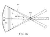
図6Aは、いくつかの実施形態に従った、例示的な小さい視聴ゾーンを有する、例示的な3Dライトフィールドディスプレイを示す図である。図6Bは、いくつかの実施形態に従った、例示的な大きい視聴ゾーンを有する、例示的な3Dライトフィールドディスプレイを示す図である。図6Aおよび図6Bは、各々、例示的な視聴ジオメトリを示している。図6Aにおいては、単一の視聴者が、像ゾーン602を有するディスプレイの前に座っており、両眼の瞳孔は、狭いビーム束FOV604を用いて達成される小さい視聴ゾーン606でカバーされる。ゾーンの最小機能幅は、眼の瞳孔距離(平均で約64mm)によって決定される。狭いFOVは、最適な視聴ロケーションの前と後ろの両方において、視聴距離の小さい変化に伴って、互いから離れ始めるので、小さい幅は、視聴距離変化に対する小さい許容度も意味する。図6Bの視聴ジオメトリにおいては、同じサイズの像ゾーン652を有するディスプレイについて、ビーム束FOV654は、かなり広く、複数の視聴者が、異なる視聴距離で、視聴ゾーン656の内部にいることを可能にする。図6Bに示されるケースにおいては、位置的な許容度は、大きい。FIG. 6A illustrates an exemplary 3D light field display with an exemplary small viewing zone, according to some embodiments. FIG. 6B illustrates an exemplary 3D light field display with an exemplary large viewing zone, according to some embodiments. FIGS. 6A and 6B each illustrate an exemplary viewing geometry. In FIG. 6A, a single viewer sits in front of a display with an image zone 602, and both eye pupils are covered with a
各ディスプレイビーム束のFOVを増大させることによって、視聴ゾーンを増大させることができる。この変化は、光エミッタ行の幅を増大させることによって、またはビームコリメーティング光学系の焦点長を変化させることによって、起こすことができる。残念ながら、より小さい焦点長は、より大きいボクセルをもたらすことがある。したがって、より良好な解像度のために、焦点長を増加させることがある。この状況は、一般に、光学系設計パラメータとデバイスサイズとの間にトレードオフが存在することを意味する。The viewing zone can be increased by increasing the FOV of each display beam bundle. This change can be made by increasing the width of the light emitter rows or by changing the focal length of the beam collimating optics. Unfortunately, a smaller focal length can result in larger voxels. Therefore, for better resolution, the focal length can be increased. This situation means that in general there is a trade-off between optics design parameters and device size.
いくつかの実施形態においては、良好な解像度の3D像を生成するために、投影される各ビュービームは、非常に良好にコリメートされ、狭い直径を有する。ビーム直径および発散が、大きい場合、ボクセルは、眼の網膜によって、大きいスポットとして知覚される。ディスプレイ面の後ろに位置付けられるボクセルは、放射されるビームの仮想延長を用いて形成され、距離がより大きくなるにつれて、眼の解像度はより低くなるので、より大きいことを許容することができる。In some embodiments, to produce a good resolution 3D image, each projected view beam is very well collimated and has a narrow diameter. If the beam diameter and divergence are large, the voxel is perceived as a large spot by the retina of the eye. Voxels located behind the display surface are formed using a virtual extension of the emitted beam and can be tolerated to be larger since the eye's resolution becomes lower as the distance becomes greater.
いくつかの実施形態については、複数の視聴者が、マルチビューディスプレイなどの、ディスプレイを見ることができる。いくつかの実施形態については、ライトフィールド(LF)ディスプレイ構造は、3次元(3D)ディスプレイを含むことができ、LFディスプレイ構造は、3Dディスプレイにわたってパターン化された方向制御可能性を有するディフューザを含み、空間的に変化する拡散方向特性を可能にする。For some embodiments, multiple viewers can view the display, such as a multi-view display. For some embodiments, the light field (LF) display structure can include a three-dimensional (3D) display, where the LF display structure includes a diffuser with directional controllability patterned across the 3D display, allowing for spatially varying diffusion directional characteristics.
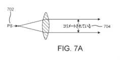
図7Aは、いくつかの実施形態に従った、1つまたは複数の幾何学的要因によって引き起こされるいかなるビーム発散もない、完全なコリメーションの例示的な理想ケースを示す図である。図7Bは、いくつかの実施形態に従った、1つまたは複数の幾何学的要因によって引き起こされる例示的なビーム発散を示す図である。図7Cは、いくつかの実施形態に従った、1つまたは複数の幾何学的要因によって引き起こされる例示的なビーム発散を示す図である。図7Aの理想的なレンズについては、達成可能な光ビームコリメーションは、2つの幾何学的要因、すなわち、光源のサイズと、レンズの焦点長とに依存する。いかなるビーム発散もない完全なコリメーション704は、単一色点光源(PS)702が、理想的な正レンズから焦点長の距離に正確に配置される、理論的ケースにおいてのみ達成することができる。このケースが、図7Aに描かれている。残念ながら、すべての現実の光源は、それらを拡張された光源(ES)にする、光が放射されるいくらかの表面積を有する。源の各点は、レンズによって別々に結像されるので、全ビームは、レンズの後でいくらか異なる方向に伝搬する、コリメートされたサブビームのグループから成ることになる。図7Aから図7Cに示されるように、源が、712、722のように、より大きくなるにつれて、全ビーム発散714、724は、増大する。この幾何学的要因は、一般に、いかなる光学的手段を用いても回避することができず、それは、相対的に大きい光源を用いた場合に、ビーム発散を引き起こす、支配的な特徴である。7A is a diagram illustrating an exemplary ideal case of perfect collimation without any beam divergence caused by one or more geometric factors, according to some embodiments. FIG. 7B is a diagram illustrating an exemplary beam divergence caused by one or more geometric factors, according to some embodiments. FIG. 7C is a diagram illustrating an exemplary beam divergence caused by one or more geometric factors, according to some embodiments. For the ideal lens of FIG. 7A, the achievable light beam collimation depends on two geometric factors: the size of the light source and the focal length of the lens.
ビーム発散を引き起こす別の、非幾何学的な特徴は、回折である。この用語は、(光の)波が障害物またはスリットに遭遇したときに起こる、様々な現象を指す。回折は、開口の隅において幾何学的な影の領域に回り込む光の曲がりである。回折効果は、すべての結像システムにおいて発生することがあり、すべての光学収差を相殺することができる完璧なレンズ設計を用いても、除去することはできない。像に残るぼやけのほとんどは、回折に由来するので、最高の光学品質に到達することができるレンズは、「回折限界」としばしば呼ばれる。回折限界レンズを用いて達成可能な角解像度は、式1の公式から算出することができる。Another non-geometric feature that causes beam divergence is diffraction. This term refers to a variety of phenomena that occur when a wave (of light) encounters an obstacle or a slit. Diffraction is the bending of light around a geometric shadow area at the corner of an aperture. Diffraction effects can occur in all imaging systems and cannot be eliminated even with a perfect lens design that can cancel all optical aberrations. Since most of the blur remaining in an image comes from diffraction, lenses that can reach the highest optical quality are often called "diffraction limited". The angular resolution achievable with a diffraction-limited lens can be calculated from the formula in Equation 1:

ここで、λは、光の波長、Dは、レンズ開口の直径である。式から、光の色(波長)と、レンズ開口サイズ(視聴者の瞳孔に入る光の直径)だけが、回折の量に影響を有するものであることが分かる。where λ is the wavelength of light and D is the diameter of the lens aperture. From the formula we can see that only the color of the light (wavelength) and the lens aperture size (diameter of the light entering the viewer's pupil) have an effect on the amount of diffraction.
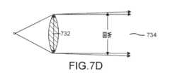
図7Dは、いくつかの実施形態に従った、回折および第1の開口サイズによって引き起こされる、例示的なビーム発散を示す図である。図7Eは、いくつかの実施形態に従った、回折および第2の開口サイズによって引き起こされる、例示的なビーム発散を示す図である。図7Fは、いくつかの実施形態に従った、回折および第3の開口サイズによって引き起こされる、例示的なビーム発散を示す図である。図7Dから図7Fは、レンズ開口サイズ732、742、752が減少したときに、ビーム発散734、744、754がどのように増大するかについての概略的な提示を示している。この効果は、実際には、結像光学系設計における一般的なルールに定式化することができ、すなわち、設計が、回折限界である場合、解像度を向上させる唯一の方法は、開口をより大きくすることである。回折は、一般に、相対的に小さい光源を用いた場合にビーム発散を引き起こす支配的な特徴である。7D illustrates an exemplary beam divergence caused by diffraction and a first aperture size, according to some embodiments. FIG. 7E illustrates an exemplary beam divergence caused by diffraction and a second aperture size, according to some embodiments. FIG. 7F illustrates an exemplary beam divergence caused by diffraction and a third aperture size, according to some embodiments. FIGS. 7D-7F show a schematic representation of how
図7A~図7Cに示されるように、拡張された源のサイズは、達成可能なビーム発散に大きい影響を有する。源の幾何学的形状または空間分布は、実際に、ビームの角度分布にマッピングされ、この特性は、光源-レンズ系の結果の「遠視野像」において見ることができる。実際には、この特性は、コリメーティングレンズが、源からの焦点距離に位置付けられる場合、源は、実際には、レンズから相対的に大きい距離に結像され、像のサイズは、系「拡大率」から決定することができることを意味する。単一の結像レンズのケースにおいては、この拡大率は、式2に示されるように、レンズと像との間の距離を源とレンズとの間の距離で除算することによって、算出することができる。As shown in Figures 7A-7C, the size of the extended source has a large effect on the achievable beam divergence. The geometry or spatial distribution of the source is actually mapped to the angular distribution of the beam, and this property can be seen in the resulting "far-field image" of the source-lens system. In practice, this property means that if a collimating lens is positioned at a focal length from the source, the source is actually imaged at a relatively large distance from the lens, and the size of the image can be determined from the system "magnification". In the case of a single imaging lens, this magnification can be calculated by dividing the distance between the lens and the image by the distance between the source and the lens, as shown in

図8Aは、いくつかの実施形態に従った、第1の屈折力を有する、例示的な像拡大レンズを示す図である。図8Bは、いくつかの実施形態に従った、第2の屈折力を有する、例示的な像拡大レンズを示す図である。図8Cは、いくつかの実施形態に従った、第3の屈折力を有する、例示的な像拡大レンズを示す図である。図8Aから図8Cは、レンズと像との間の3つの異なる距離806、836、866について、式2を例示しており、距離806、836、866が、増加するにつれて、より大きい像808、838、868が、もたらされる。(固定された高さ802、832、862を有する)源とレンズとの間の距離804、834、864が、固定される場合、レンズ曲率を用いてレンズの屈折力を変化させることによって、異なる像距離を達成することができる。しかし、像距離が、レンズ焦点長と比較して、どんどん大きくなるとき、レンズ屈折力の変化は、どんどん小さくなり、レンズが、放射された光を、角度分布にマッピングされる源の空間分布を有するビームになるように効果的にコリメートし、焦点調節なしに、源像が、形成される状況に接近する。8A illustrates an exemplary image magnifying lens having a first refractive power, according to some embodiments. FIG. 8B illustrates an exemplary image magnifying lens having a second refractive power, according to some embodiments. FIG. 8C illustrates an exemplary image magnifying lens having a third refractive power, according to some embodiments. FIGS. 8A-8C illustrate
フラットなフォームファクタのゴーグルレス3Dディスプレイにおいては、ディスプレイ投影レンズは、一般に、フラット構造を達成するために、非常に小さい焦点長を有し、単一のディスプレイ光学系セルからのビームは、相対的に大きい視聴距離に投影される。これは、光のビームが、視聴者に伝搬するときに、源が、高倍率で効果的に結像されることを意味する。例えば、源サイズが、50μm×50μm、投影レンズ焦点長が、1mm、視聴距離が、1mである場合、拡大率は、1000:1であり、源幾何学像は、50mm×50mmである。これは、この直径50mmのアイボックスの中においては、単一の光エミッタを、一方の眼だけを用いて見ることができることを意味する。In a flat form factor goggle-less 3D display, the display projection lens typically has a very small focal length to achieve a flat structure, and the beam from a single display optics cell is projected to a relatively large viewing distance. This means that as the beam of light propagates to the viewer, the source is effectively imaged with high magnification. For example, if the source size is 50 μm×50 μm, the projection lens focal length is 1 mm, and the viewing distance is 1 m, the magnification is 1000:1 and the source geometric image is 50 mm×50 mm. This means that within this 50 mm diameter eyebox, a single light emitter can be seen using only one eye.
1000:1の拡大率を有するレンズについては、源が、100μmの直径を有する場合、結果の像は、100mm幅であり、眼の瞳孔間の平均距離は、64mmにすぎないので、同じピクセルが、両眼で同時に可視であることがある。この後者のケースにおいては、両眼が、同じ像を見るので、立体視3D像は、形成されない。この例示的な計算は、光源サイズ、レンズ焦点長、視聴距離などの幾何学的パラメータが、どのように互いに結びついているかを示している。For a lens with a magnification of 1000:1, if the source has a diameter of 100 μm, the resulting image is 100 mm wide, and the same pixel can be visible to both eyes simultaneously, since the average distance between the pupils of the eyes is only 64 mm. In this latter case, no stereoscopic 3D image is formed, since both eyes see the same image. This exemplary calculation shows how geometric parameters such as source size, lens focal length, and viewing distance are linked to each other.
幾何学的効果および回折効果の両方が、一体となって働き、LFディスプレイピクセル設計は、特定のボクセル解像度を達成するために、幾何学的効果と回折効果とのバランスをとることができる。これは、非常に小さい光源を用いる場合に強調されるが、そのわけは、光学系測定が、光の波長により近くなり、回折効果が、性能を支配し始めるためである。図9Aから図9Dは、1つおよび2つの拡張された源が、固定された倍率で固定された距離に結像されるケースにおいて、幾何学的効果および回折効果がどのように一緒に働くかを例示している。図9Aから図9Dは、異なる幾何学的倍率および回折効果についての光源スポットサイズを示している。Both geometric and diffractive effects work together, and LF display pixel designs can balance geometric and diffractive effects to achieve a particular voxel resolution. This is accentuated when using very small light sources, as optical system measurements get closer to the wavelength of light and diffractive effects start to dominate performance. Figures 9A-9D illustrate how geometric and diffractive effects work together in the case of one and two extended sources imaged at a fixed distance with a fixed magnification. Figures 9A-9D show the source spot size for different geometric magnifications and diffractive effects.
図9Aは、いくつかの実施形態に従った、例示的な第1の光源およびレンズ構成を示す図である。図9Aの例示的な構造については、拡張された源(ES)902が、拡大レンズから10cmの焦点長904のところに配置される。例示的なレンズ開口906を通過する光ビームは、5cm隔たっている。光ビームは、GI908として示される幾何学像を有する。光源は、DI910によって示される回折像高さを有する。図9Aは、相対的に小さいレンズ開口サイズを示しており、幾何学像(GI)908は、回折像(DI)910をはるかに大きくする際の回折に由来する、ぼかしによって取り囲まれる。Figure 9A illustrates an exemplary first light source and lens configuration, according to some embodiments. For the exemplary configuration of Figure 9A, an extended source (ES) 902 is placed at a
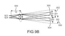
図9Bは、いくつかの実施形態に従った、例示的な第2の光源およびレンズ構成を示す図である。図9Bの例示的な構造については、2つの拡張された源922、924が、拡大レンズから10cmの焦点長926のところに配置される。例示的なレンズ開口928を通過する光ビームは、5cm隔たっている。光ビームは、それぞれGI1(930)およびGI2(934)の高さを用いて示される、それぞれの像を生成する。各光源は、それぞれDI1(932)およびDI2(936)によって示される、それぞれの回折像高さを有する。図9Bは、2つの拡張された源が、並べて配置され、同じ小開口レンズを用いて結像されるケースを示している。両方の源のGIは、分離されているとしても、回折像は、重なり合うので、2つの源像を分解することはできない。実際には、これは、2つの別個の光源を用いる場合と、両方の別個のエミッタのエリアをカバーする1つのより大きい源を用いる場合とで、結果の源像サイズは、同じであることがあるので、光源サイズの縮小が、達成可能なボクセル解像度を改善しないことがあることを意味する。2つの源像を別個のピクセル/ボクセルとして分解するために、結像レンズの開口サイズを増大させることがある。9B illustrates an exemplary second light source and lens configuration, according to some embodiments. For the exemplary configuration of FIG. 9B, two
図9Cは、いくつかの実施形態に従った、例示的な第3の光源およびレンズ構成を示す図である。図9Cの例示的な構造については、拡張された源(ES)942が、拡大レンズから10cmの焦点長944のところに配置される。例示的なレンズ開口946を通過する光ビームは、10cm隔たっている。光ビームは、GI948の高さを用いて示される像を生成する。光源は、DI950によって示される回折指数を有する。図9Aと比較すると、距離GI908、948は、両方の図において同じであるが、図9Cにおける回折像高さ950は、図9Aにおける回折像高さ910よりも小さい。図9Cは、図9Aおよび図9Bと同じ焦点長レンズを示しているが、拡張された源942を結像する際に、より大きい開口946が、使用される。回折は、低減され、回折像は、倍率が固定されているので同じサイズのままである幾何学像よりも僅かだけ大きくなることができる。9C is a diagram illustrating an exemplary third light source and lens configuration, according to some embodiments. For the exemplary configuration of FIG. 9C, an extended source (ES) 942 is placed at a
図9Dは、いくつかの実施形態に従った、例示的な第4の光源およびレンズ構成を示す図である。図9Dの例示的な構造については、2つの拡張された源(962、964)が、拡大レンズから10cmの焦点長966のところに配置される。例示的なレンズ開口968を通過する光ビームは、10cm隔たっている。光ビームは、それぞれGI1(970)およびGI2(974)の高さを用いて示される、それぞれの像を生成する。各光源は、それぞれDI1(972)およびDI2(976)によって示される、それぞれの回折像高さを有する。図9Bと比較して、距離GI1(930、970)およびGI2(934、974)は、両方の図において同じであるが、図9Dにおける回折像高さ(972、976)は、図9Bにおける回折像高さ(932、936)よりも小さい。図9Dにおいては、回折像が、重なり合っていないので、2つのスポットを分解することができ、それによって、2つの異なる源の使用、およびボクセルグリッドの空間解像度の向上を可能にする。9D is a diagram illustrating an exemplary fourth light source and lens configuration, according to some embodiments. For the exemplary configuration of FIG. 9D, two extended sources (962, 964) are placed at a
非特許文献1は、いわゆるμLEDの使用に基づいた、新しいディスプレイ技術について論じている。マイクロLEDは、今日使用されている他のLEDチップと同じ技法を用いて、同じ材料から一般に製造される、LEDチップである。しかしながら、μLEDは、一般に利用可能なコンポーネントの小型化バージョンであり、μLEDは、1μm~10μmほどに小さく作成することができる。μLEDに伴う課題の1つは、ディスプレイ製造において、非常に小さいコンポーネントをどのように扱うかである。非特許文献2は、これまで製造されてきた最も密なマトリックスの1つ、3μmピッチで組み立てられた2μm×2μmのチップについて論じている。μLEDは、TVにおけるバックライトコンポーネントとして使用されてきたが、μLEDは、近い将来、μディスプレイ市場において、OLEDに挑戦することが期待されている。OLEDと比較して、多くのμLEDは、より安定したコンポーネントであり、高い光強度を生成することができ、それが、μLEDを、ヘッドマウントディスプレイシステム、(LEDマトリックスとしての)アダプティブ自動車ヘッドランプ、TVバックライトなど、多くの用途において使用することを可能にする。μLEDは、オンとオフとの切り替えを非常に高速に行うことができる、個別にアドレス指定可能な光エミッタの非常に密なマトリックスを使用する、3Dディスプレイにおいても使用することができる。
剥き出しのμLEDチップは、約20~30nmのスペクトル幅を有する特定の色を放射することができる。白色源は、青色またはUV LEDによって放射された光を、より広い白色光放射スペクトルに変換する、蛍光物質の層を用いて、チップをコーティングすることによって、生成することができる。別個の赤色、緑色、および青色LEDチップを並べて配置することによって、フルカラー源も、生成することができる。これらの3原色の組み合わせは、別々の色放射が、人間の視覚系によって組み合わされたとき、フルカラーピクセルの感覚を生み出すことができる。非常に密なマトリックスは、10μmを下回る全幅(3×3μmピッチ)を有する、自発光型フルカラーピクセルの製造を可能にすることができる。Bare μLED chips can emit specific colors with a spectral width of about 20-30 nm. White light sources can be produced by coating the chips with a layer of phosphor that converts the light emitted by blue or UV LEDs into a broader white light emission spectrum. Full-color sources can also be produced by placing separate red, green, and blue LED chips side-by-side. The combination of these three primary colors can create the sensation of a full-color pixel when the separate color emissions are combined by the human visual system. A very dense matrix can allow the fabrication of self-emissive full-color pixels with a total width below 10 μm (3×3 μm pitch).
半導体チップからの光取り出し効率は、LED構造の電気-光効率を示すパラメータである。取り出し効率を高め、制限された電源を有するモバイルデバイスなどにおいて、電気エネルギーを効率的に利用する、LEDベースの光源を構築することを可能にすることを目的とする、いくつかの方法が存在する。特許文献1において提示された1つの方法は、LEDチップの上に直接的に統合される成形プラスチック光学要素の使用に基づいていると理解される。より低い屈折率差のせいで、プラスチック形状の統合は、空気によって取り囲まれたチップと比較して、より多くの光をチップ材料から取り出す。プラスチック形状は、また、プラスチック片からの光取り出しを増強し、放射パターンをより指向的にする方法で、光を誘導する。特許文献2において提示された別の方法は、μLEDチップからの光取り出しを増強すると理解される。これは、半導体チップの前面に対してより直角であり、光が高屈折率材料から逃げることを可能にする、光放射角度に都合がよい形にチップを成形することによって行われる。これらの構造もチップから放射される光を誘導する。後者のケースにおいては、取り出し効率は、一般的なμLEDと比較して、2倍良好であると算出され、周囲の半球に均一に分散する、放射された光のランバート拡散を有する、一般的なチップと比較して、より多くの光が、30°の放射円錐に放射される。The light extraction efficiency from a semiconductor chip is a parameter that indicates the electrical-optical efficiency of an LED structure. There are several methods that aim to increase the extraction efficiency and make it possible to build LED-based light sources that efficiently utilize electrical energy, such as in mobile devices with limited power sources. One method presented in US Pat. No. 6,233,633 is understood to be based on the use of molded plastic optical elements integrated directly on top of the LED chip. Due to the lower refractive index difference, the integration of the plastic shape extracts more light from the chip material compared to a chip surrounded by air. The plastic shape also enhances the light extraction from the plastic piece and guides the light in a way that makes the radiation pattern more directional. Another method presented in US Pat. No. 6,233,633 is understood to enhance the light extraction from the μLED chip. This is done by shaping the chip in a shape that favors the light emission angle, which is more perpendicular to the front surface of the semiconductor chip and allows the light to escape the high refractive index material. These structures also guide the light emitted from the chip. In the latter case, the extraction efficiency is calculated to be twice as good as that of a typical μLED, and more light is emitted in a 30° emission cone compared to a typical chip with a Lambertian diffusion of the emitted light, which is uniformly distributed in the surrounding hemisphere.
液晶(LC)材料に基づいた、複数のコンポーネントおよびシステムが、光伝播の電気的制御のために、開発されており、そのようなコンポーネントは、より低いコストで大量に入手可能である。いくつかの実施形態については、LCベースの調整可能なコンポーネントを、3Dディスプレイにおいて使用することができる。そのようなLCコンポーネントは、機械的なパーツを動かさずに、光ビーム調整を引き起こすことができることがある。LCベースのコンポーネントは、一般に、直線偏光を使用し、これは、光学効率を低下させ、電力消費を増加させることがある。LCDは、一般に、偏光依存デバイスであるので、光伝搬制御コンポーネントは、効率に高いコストをかけずに、3Dディスプレイにおいて使用することができる。非特許文献3は、例えば、OLEDまたはμLEDに基づいたディスプレイパネルについてのコンポーネント透過率の増加を可能にする、偏光依存性のないビームステアリングのために使用することができる、(より一般的なネマチック相結晶の代わりに)コレステリックLCを使用することについて説明している。Several components and systems based on liquid crystal (LC) materials have been developed for electrical control of light propagation, and such components are available in large quantities at lower cost. For some embodiments, LC-based tunable components can be used in 3D displays. Such LC components may be able to cause light beam adjustment without moving mechanical parts. LC-based components generally use linearly polarized light, which may reduce optical efficiency and increase power consumption. Since LCDs are generally polarization-dependent devices, light propagation control components can be used in 3D displays without high cost of efficiency. Non-Patent Document 3 describes the use of cholesteric LCs (instead of the more common nematic phase crystals) that can be used for polarization-independent beam steering, enabling increased component transmittance for display panels based on OLEDs or μLEDs, for example.
特許文献3は、自動立体視3Dディスプレイにおいて、LCコンポーネントを電気的に切り替え可能な視差バリアとして使用することについて説明していると理解される。LC層が、アクティブ化されたとき、黒い格子構造が、いくつかのディスプレイピクセルビュー方向をブロックし、異なる像を視聴者の2つの眼に示すことができる。アクティブ化された格子がない場合、ディスプレイは、通常の2Dディスプレイとして機能する。特許文献4は、LC材料分子のいくつかを電流を用いて再配向することによって、密なピクセルマトリックスの上にレンチキュラレンズ構造を形成する際に、LC層を使用することについて説明していると理解される。LC層は、複雑な電極設計を使用することができるが、LCレンズが異なるビュー方向にピクセル像を投影するように、2Dモードと3Dモードとの間で切り替えを行うために、LC層を使用することができる。後者のモードにおいては、マルチビュー像を生成するために、空間多重化だけが使用されるので、空間解像度を代償にして、複数のビューを獲得することができる。非特許文献4は、電気的に形成されたレンチキュラLCレンズをディスプレイ面を通して走査し、時間多重化についての可能性を追加する、提案されたシステムについて論じている。このケースにおいては、走査アクションに同期したピクセルは、単一の走査タイムフレーム内において、数回アクティブ化することができ、いくつかの追加ビューを生成する。US Patent No. 5,399,633 is understood to describe the use of LC components as electrically switchable parallax barriers in autostereoscopic 3D displays. When the LC layer is activated, a black lattice structure blocks some display pixel view directions and different images can be shown to the two eyes of the viewer. In the absence of an activated lattice, the display functions as a normal 2D display. US Patent No. 5,399,633 is understood to describe the use of an LC layer in forming a lenticular lens structure on top of a dense pixel matrix by reorienting some of the LC material molecules with an electric current. The LC layer can use a complex electrode design, but can be used to switch between 2D and 3D modes so that the LC lenses project pixel images in different view directions. In the latter mode, multiple views can be obtained at the expense of spatial resolution, since only spatial multiplexing is used to generate a multi-view image. Non-Patent Document 4 discusses a proposed system in which an electrically formed lenticular LC lens is scanned through the display surface, adding the possibility for time multiplexing. In this case, pixels synchronized to the scanning action can be activated several times within a single scanning time frame, generating several additional views.
高複屈折材料として、LC層は、2つの直交する方向において、異なる屈折率を有する。この特性は、非特許文献5に従って、2つのLC層を含む構造を用いて、2つのビームステアリング状態の間で切り替えを行うために、例えば、高分子マイクロプリズムと一緒に使用することができる。第1の能動LC層は、例えば、電極を含む2つのガラスシートの間に配置される。第2の受動層は、ガラスまたは高分子基板と高分子マイクロプリズムシートとの間に形成される。能動LC層は、電圧が印加されたとき、入射ビーム直線偏光を、伝搬方向に垂直に90°回転させる。この回転は、デバイスの第2の部分において、複屈折受動LC層の屈折率のうちのどちらが使用されるかを選択する。ステアリングデバイスの第1の状態においては、受動LC層とマイクロプリズム高分子材料との間の屈折率差は、非常に小さいので、光の屈曲は、発生しない。第2の状態においては、率差は、境界面において、光線が事前決定された角度に曲がることを引き起こす。この角度は、通常、かなり小さい(約1°)が、角度は、例えば、(非特許文献7に従って)LC層の後にホログラフィック回折格子を追加することによって、または特許文献5に従って理解されるように、いくつかの偏光ベースのビームステアリングコンポーネントを積み重ねて、例えば、±15°ほどの大きさの角度に達することを可能にすることによって、増加させることができる。As a highly birefringent material, the LC layer has different refractive indices in two orthogonal directions. This property can be used, for example, together with polymer microprisms, to switch between two beam steering states using a structure containing two LC layers according to [5]. The first active LC layer is, for example, placed between two glass sheets containing electrodes. The second passive layer is formed between a glass or polymer substrate and a polymer microprism sheet. The active LC layer rotates the incoming beam linear polarization by 90° perpendicular to the propagation direction when a voltage is applied. This rotation selects which of the refractive indices of the birefringent passive LC layer is used in the second part of the device. In the first state of the steering device, the refractive index difference between the passive LC layer and the microprism polymer material is very small, so no bending of light occurs. In the second state, the index difference causes the light ray to bend at a pre-determined angle at the interface. This angle is usually quite small (around 1°), but the angle can be increased, for example, by adding a holographic diffraction grating after the LC layer (according to non-patent document 7), or by stacking several polarization-based beam steering components, as understood according to patent document 5, making it possible to reach angles as large as ±15°, for example.
特許文献6は、硬質高分子レンチキュラシート構造の前で光ビーム調整LC要素が使用される、ハイブリッドシステムについて説明していると理解され、非特許文献7は、硬質高分子レンチキュラシート構造の後でLC要素を使用して、ピクセル位置およびレンチキュラ光学系によって決定される方向の間に追加の角度ビュー方向を生成することを可能にする。これらのケースにおいては、3Dマルチビューディスプレイにおいて、時間多重化が、空間多重化と一緒に使用される。同じLCベースのビームステアリングスクリーンコンポーネントも、非特許文献8に従って、複数のプロジェクタとともに、同様の方式で使用することができる。
ビーム角度ステアリングに加えて、(特許文献7、特許文献8、および特許文献9において説明されていると理解される)ハイブリッド構造を有するLCベースのコンポーネントは、機械的な動きを伴わずに、ビーム焦点を調整するために使用することが可能であると理解される。この電子的な焦点調整は、非特許文献9に従って、立体視3Dディスプレイ仮想像を、眼から異なる焦点距離に移動させて、像をより自然に見えるようにすることができる、ヘッドマウントデバイスにおいて利用することができる。ビーム焦点調整は、非特許文献10に従って、投影される像焦点面の位置または形状を調整することによって、ゴーグルレス3Dディスプレイにおいても利用することができる。例えば、例示的な3D/LFディスプレイ特許または論文において説明されているケースの多くにおいて、焦点調整は、投影される像全体を直接的に変更する。例えば、非特許文献11は、焦点調整可能なマイクロレンズのアレイを含む、例示的なレンズシステムについて説明している。In addition to beam angle steering, it is understood that LC-based components with hybrid structures (understood as described in U.S. Pat. No. 6,393,316, U.S. Pat. No. 6,393,635, and U.S. Pat. No. 6,393,635) can be used to adjust the beam focus without mechanical movement. This electronic focus adjustment can be utilized in head-mounted devices that can move the stereoscopic 3D display virtual image to different focal distances from the eyes to make the image appear more natural, according to U.S. Pat. No. 6,393,316. Beam focus adjustment can also be utilized in goggle-less 3D displays by adjusting the position or shape of the projected image focal plane, according to U.S. Pat. No. 6,393,316. For example, in many of the cases described in the exemplary 3D/LF display patents or papers, the focus adjustment directly changes the entire projected image. For example, U.S. Pat. No. 6,393,316 describes an exemplary lens system that includes an array of focus-adjustable microlenses.
図10は、いくつかの実施形態に従った、例示的な可変焦点長マイクロレンズアレイを示す図である。図10は、バリフォーカルマイクロレンズの構造および機能を示している。ガラス基板1006とマイクロレンズアレイ(MLA)1002との間に配置されたLC層1004が、存在する。両方の境界材料境界面は、LC層能動調整のための陽極および陰極として機能する、透明な導電性インジウムスズ酸化物(ITO)パターンコーティング1010、1012を有する。電圧が、印加された場合、電界が、LC分子を回転させ、材料の屈折率が、直線偏光方向に変化する。いくつかの実施形態については、ネマチック液晶材料を用い、0~12Vの範囲内の低い電圧を用いる場合、率変化の量は、約0.2のオーダである。いくつかの実施形態については、LC材料の屈折率(約1.5)は、MLA材料の屈折率に近くなるように設定される。Figure 10 is a diagram of an exemplary variable focal length microlens array, according to some embodiments. Figure 10 illustrates the structure and function of a varifocal microlens. There is an
図10は、直線偏光だけを透過させる偏光子コンポーネント1008に最初に当たる、コリメートされた光1016の3つの例示的なビームを示している。ビームは、印加された電圧を用いてLC層の屈折率を調整することによって、焦点に集まり集束ビーム1020となるように、発散ビーム1024として発散するように、またはコリメートされたビーム1022として無変化のままであるようにすることができる。LCの率が、MLAの率と一致するように調整された場合、境界面は消失し、ビームコリメーションは、影響されない。率が、MLAの率値を下回る、または上回るになるように調整された場合、ビームは、屈折し、実焦点1018または仮想焦点1014が、構造の前または後ろに生成される。Figure 10 shows three example beams of collimated light 1016 that first strike a
電圧が、LC材料に印加されたとき、結晶は、LC材料層上において生成された電界によって指示される特定の方向に整列する。電圧がない場合、結晶は、ランダムな向き、または異なる技法を用いて材料を準備することによって作られた、他の何らかの秩序ある向きにあることができる。電圧レベルは、配向の量に影響し、材料の光学特性を調整するために、電圧レベルを使用することができる。LC材料層の両側上の電極が、局所電界を調整することができるような方法で、パターン化された場合、そうでなければ均質なLC層内の局所的な結晶配向を調整することができる。適切な電極設計を用いた場合、LC層上のあるエリア上における電界の漸進的な調整を用いて、屈折率を調整することによって、例えば、LCマイクロレンズを生成することができる。When a voltage is applied to the LC material, the crystals align in a particular direction dictated by the electric field created on the LC material layer. In the absence of a voltage, the crystals can be randomly oriented or in some other ordered orientation created by preparing the material using different techniques. The voltage level affects the amount of orientation and can be used to tune the optical properties of the material. If electrodes on both sides of the LC material layer are patterned in such a way that the local electric field can be adjusted, the local crystal orientation in an otherwise homogeneous LC layer can be adjusted. With the appropriate electrode design, gradual adjustment of the electric field over an area on the LC layer can be used to tune the refractive index, creating, for example, LC microlenses.
いくつかの実施形態については、視聴者の眼が、追跡されている場合、拡散の角度を変更することができる。いくつかの実施形態については、拡散の角度が、変更される場合、光のより大きい広がりを補償し、視聴ウィンドウ内のある点において同じ放射照度を保つために、例えば、μLEDの光放射強度を増加させることができる。いくつかの実施形態については、拡散の角度が、変更される場合、例えば、光源の数を増加または減少させることができる。For some embodiments, the angle of diffusion can be changed if the viewer's eyes are tracked. For some embodiments, if the angle of diffusion is changed, the light emission intensity of the μLEDs can be increased, for example, to compensate for the larger spread of light and keep the same irradiance at a point within the viewing window. For some embodiments, if the angle of diffusion is changed, the number of light sources can be increased or decreased, for example.
図10は、LC材料に基づいた、焦点調整可能なマイクロレンズの概略図である。基本的な考え方は、LC材料層の周りの他の境界層内に固定された、3つの異なるマイクロレンズ形状において、電界を局所的に調整するというものである。一番上のケースにおいては、LC屈折率は、レンズ材料の率よりも小さくなるように(液晶を配向させることによって)調整され、コリメートされたビームは、ある点に焦点を結ぶ。描かれた中央のケースにおいては、LC材料は、マイクロレンズと同じ屈折率を有し、光学境界面を消失させ、光は、コリメーションに対する変化なしに、透過させられる。提示された下のケースにおいては、LC材料屈折率は、レンズ材料よりも高い値に調整され、実質的に、到来ビームを発散させる、負焦点長レンズを作成する。非特許文献12は、この考えをより詳細に論じている。Figure 10 is a schematic diagram of a focus-tunable microlens based on LC material. The basic idea is to locally tune the electric field at three different microlens shapes fixed in other boundary layers around the LC material layer. In the top case, the LC refractive index is tuned (by orienting the liquid crystals) to be smaller than that of the lens material, and the collimated beam is focused to a point. In the middle case depicted, the LC material has the same refractive index as the microlens, vanishing the optical interface and the light is transmitted without any change to the collimation. In the bottom case presented, the LC material refractive index is tuned to a higher value than the lens material, essentially creating a negative focal length lens that diverges the incoming beam. Non-Patent Document 12 discusses this idea in more detail.
非特許文献13は、切り替え可能または調整可能な回折格子において、液晶材料を使用することについて説明している。液晶材料は、ディフューザにおいても使用することができる。切り替え可能な回折格子は、主な光学パラメータが格子周期である回折格子の式に従って、光ビームを、異なる方向に伝搬する複数の子ビームに分割する際に使用される。このパラメータは、必要とされる高密度可変屈折率パターンをLC材料に誘導するのに、十分に精巧であることを必要とする、LC回折格子電極設計によって影響されることがある。調整可能なディフューザが、光を散乱するために使用され、一般に、それらは、透明状態と半透明状態との間の切り替えを電気的に行うことができる。これらのコンポーネントは、印加された電界の下である特定の変化を実行するように変更された、LC材料の電気的な調整に基づいている。Non-Patent Document 13 describes the use of liquid crystal materials in switchable or tunable diffraction gratings. Liquid crystal materials can also be used in diffusers. Switchable diffraction gratings are used to split a light beam into multiple child beams propagating in different directions according to the diffraction grating formula, whose main optical parameter is the grating period. This parameter can be influenced by the LC diffraction grating electrode design, which needs to be sophisticated enough to induce the required high density variable refractive index pattern in the LC material. Tunable diffusers are used to scatter the light, and typically they can be electrically switched between transparent and translucent states. These components are based on the electrical tuning of LC materials, which are modified to perform certain changes under an applied electric field.
非特許文献14は、高分子安定型コレステリックテクスチャ(PSCT)手法に基づいた、LCディフューザについて説明している。これらのコンポーネントにおいては、透明/散乱材料は、テクスチャが液晶材料を含むような方法で準備された。非特許文献15および非特許文献16に従うと、別の調整可能なディフューザタイプは、一致した屈折率を有する光学的に透明な高分子マトリックス内に埋め込まれた、マイクロメータサイズのLC液滴を有する、高分子安定化液晶(PSLC)を使用する。電界が、PSLC材料に印加された場合、整列した液滴の屈折率が、変化させられ、液滴と周囲の高分子との間の境界面が、光を屈折し始める。これは、調整可能なディフューザが、アクティブ化されたとき、光が、材料内部に埋め込まれた小さいLC粒子から、すべての方向に散乱されることを意味する。そのような材料ベースの散乱については、光拡散効果は、大きい傾向にあるが、光の大部分が、散乱されて戻ってくるので、コンポーネントを通り抜ける透過は、低下し、散乱光の角度分布に対する制御がなくなる傾向がある。Non-Patent Document 14 describes an LC diffuser based on a polymer stabilized cholesteric texture (PSCT) approach. In these components, the transparent/scattering material was prepared in such a way that the texture contains liquid crystal material. According to Non-Patent Document 15 and Non-Patent Document 16, another tunable diffuser type uses polymer stabilized liquid crystal (PSLC) with micrometer-sized LC droplets embedded in an optically transparent polymer matrix with a matched refractive index. When an electric field is applied to the PSLC material, the refractive index of the aligned droplets is changed and the interface between the droplets and the surrounding polymer starts to refract the light. This means that when the tunable diffuser is activated, the light is scattered in all directions from the small LC particles embedded inside the material. For such material-based scattering, the light diffusion effect tends to be large, but the transmission through the component tends to be reduced and there is no control over the angular distribution of the scattered light, since a large part of the light is scattered back.
いくつかのハイブリッドLCディフューザ光学構造が、開発されてきた。特許文献10は、切り替え可能LCディフューザ層を光拡散面構造と組み合わせることについて説明していると理解される。拡散面は、調整可能な部分におそらくは積層された、別個に製造された箔であり、または拡散面は、LCディフューザの外面に直接的にパターン化された、統合構造であることができる。静的拡散面の拡散特性は、調整可能なディフューザのオンとオフとを切り替えることによって、増加または減少させられる。今は特許文献12である特許文献11は、自動立体視ディスプレイを2D表示モードと3D表示モードとの間で切り替える際に、レンチキュラマイクロレンズとLCディフューザ層との組み合わせが使用される、ハイブリッド構造について説明していると理解される。この切り替えは、LCディフューザをオンに切り替えることによって、マルチビューディスプレイの角度分布を拡散することによって行われる。特許文献13も、2D表示モードと3D表示モードとの間で切り替えを行うことについて説明していると理解される。透明状態と半透明状態との間で切り替えを行うことができる、電気的に調整可能なLCディフューザは、特許文献14および特許文献15において説明されていると理解されるような、複数の切り替え可能なスクリーンへの連続像投影に基づいた、例えば、ボリュームディスプレイにおいて、広く利用されてきた。そのようなコンポーネントは、光をすべての方向に均一に散乱する。この特徴は、コンポーネントが、ボクセルがすべての方向から見えるような、ボリュームディスプレイにおいて使用されるとき、有用なことがある。しかしながら、そのような体積3D像は、オクルージョンを適切に生成することができず、それらを半透明でやや不自然に見えるようにする。Several hybrid LC diffuser optical structures have been developed. US Pat. No. 6,299,433 is understood to describe combining a switchable LC diffuser layer with a light diffusing surface structure. The diffusing surface can be a separately manufactured foil, possibly laminated to the adjustable portion, or the diffusing surface can be an integral structure, patterned directly on the outer surface of the LC diffuser. The diffusing properties of the static diffusing surface are increased or decreased by switching the adjustable diffuser on and off. US Pat. No. 6,299,433, now US Pat. No. 6,299,433, is understood to describe a hybrid structure in which a combination of lenticular microlenses and an LC diffuser layer is used in switching an autostereoscopic display between 2D and 3D display modes. The switching is performed by diffusing the angular distribution of the multi-view display by switching on the LC diffuser. US Pat. No. 6,299,433 is also understood to describe switching between 2D and 3D display modes. Electrically tunable LC diffusers that can be switched between transparent and semi-transparent states have been widely used, for example, in volumetric displays based on sequential image projection onto multiple switchable screens, as understood to be described in U.S. Pat. No. 6,299,333 and U.S. Pat. No. 6,399,353. Such components scatter light uniformly in all directions. This feature can be useful when the components are used in volumetric displays, where voxels are visible from all directions. However, such volumetric 3D images cannot generate occlusions properly, making them appear semi-transparent and somewhat unnatural.
光拡散コンポーネントを作成するいくつかの方法が、存在する。光散乱構造は、例えば、材料内部散乱、回折、または表面散乱に基づくことができる。特定の角度光分布を生成する面構造を生成するために、回折方法および表面散乱方法を使用することができる。多くの材料ベースの拡散方法については、光散乱粒子が、いくつかの媒体内においてはサスペンドしており、または材料が、光を拡散する固定された内部構造を有するので、構造を製造するのがより困難である。There are several methods to create light diffusing components. Light scattering structures can be based on, for example, material internal scattering, diffraction, or surface scattering. Diffraction and surface scattering methods can be used to create surface structures that generate specific angular light distributions. For many material-based diffusion methods, it is more difficult to fabricate the structures because the light scattering particles are suspended in some medium or the material has a fixed internal structure that diffuses the light.
今は特許文献17である特許文献16は、表面散乱ベースのディフューザについて説明していると理解される。それらの光整形ディフューザ(LSD)は、ホログラフィックに記録されたマスタから複製される、表面レリーフ構造を使用する。これらの擬似ランダムで非周期的な構造は、いくつかの非常に特定的な角度分布に光を拡散することができる。この拡散パターンは、到来光を操作し、それの方向を非常に小さいスケールで変化させる、特定の勾配分布を有する、マイクロ構造を作成することによって、設計することができる。そのような構造は、後方散乱のせいで光が浪費されることがないので、正確な拡散角度制御、およびコンポーネントを通り抜ける効率的な光透過のために、使用することができる。It is understood that US Pat. No. 5,399,433, now US Pat. No. 5,499,433, describes a surface scattering based diffuser. Their light shaping diffusers (LSD) use surface relief structures that are replicated from a holographically recorded master. These pseudo-random, non-periodic structures can diffuse light into some very specific angular distribution. This diffusion pattern can be engineered by creating microstructures with specific gradient distributions that manipulate the incoming light and change its direction on a very small scale. Such structures can be used for precise diffusion angle control and efficient light transmission through the component, since no light is wasted due to back scattering.
いくつかの実施形態については、光学像ディスプレイ構造は、調整可能な光拡散コンポーネントを含むことができる。方法のいくつかの実施形態は、調整可能な光拡散コンポーネントを用いて、光を拡散することを含むことができる。いくつかの実施形態については、光学像ディスプレイ構造は、3Dマルチビューディスプレイデバイスを含むことができる。方法のいくつかの実施形態は、3Dマルチビューディスプレイデバイスを用いて、マルチビュー3D像を表示することを含むことができる。いくつかの実施形態については、調整可能な光拡散コンポーネントは、表面効果液晶(SELC)ディフューザであることができる。ディフューザは、角度選択的拡散コンポーネントであることができ、それは、機械的な動きを伴わずに、アクティブ化することができる。SELCディフューザは、例えば、複屈折材料と、非常に小さいスケールの面特徴を有する基板材料との間に存在することができる、光学境界面から光を散乱する。SELCディフューザの液晶材料は、光偏光方向または材料屈折率を変更するために使用され、それが、設計された境界面において、光ビームを透過させ、または散乱する。(高分子分散型液晶(PDLC)および高分子安定化コレステリックテクスチャ(PSCT)など)いくつかの材料ベースのディフューザは、材料内部散乱のせいで、垂直方向および水平方向の両方において、同じ光分布を生成することがある。光学境界面散乱の使用は、より高い透過効率を可能にし、特定の光伝播方向に対して選択的に散乱特性を調整することができる、3Dディスプレイにおけるコンポーネントの使用を可能にすることができる。For some embodiments, the optical image display structure can include an adjustable light diffusion component. Some embodiments of the method can include diffusing light using the adjustable light diffusion component. For some embodiments, the optical image display structure can include a 3D multi-view display device. Some embodiments of the method can include displaying a multi-view 3D image using the 3D multi-view display device. For some embodiments, the adjustable light diffusion component can be a surface effect liquid crystal (SELC) diffuser. The diffuser can be an angle-selective diffusion component that can be activated without mechanical movement. The SELC diffuser scatters light from an optical interface that can exist, for example, between a birefringent material and a substrate material with very small scale surface features. The liquid crystal material of the SELC diffuser is used to change the light polarization direction or material refractive index, which transmits or scatters the light beam at the designed interface. Some material-based diffusers (such as polymer dispersed liquid crystal (PDLC) and polymer stabilized cholesteric texture (PSCT)) may produce the same light distribution in both vertical and horizontal directions due to material internal scattering. The use of optical interface scattering can allow for higher transmission efficiency and enable the use of components in 3D displays whose scattering properties can be selectively tuned for specific light propagation directions.
SELCディフューザは、多くの異なるタイプの3Dディスプレイにおいて使用することができ、他の構造よりも機能性および/または性能を向上させることができる。3Dディスプレイに加えて、SELCディフューザは、例えば、LEDランプを用いて生成された照明パターンを制御するために、使用することができる。SELCディフューザは、広いエリアにわたって均一に光を拡散するために、またはスポットライトを投影するために、電子的に調整することができる。SELCディフューザは、例えば、(光がガラス窓を通過することを許す)透明モードと、(光がガラス窓を通過することをブロックする)半透明モードとの間で切り替えを行うことができる、セキュリティ/プライバシガラス窓において、使用することができる。SELCディフューザについての使用のさらなる例は、特定の調整可能な照明パターンを使用する光学測定デバイス、レンズ開口にわたって人工的なボケ効果を生成することができる写真効果、および光チャネル間のスイッチとして調整可能なディフューザを使用することができる光通信モジュールを含む。SELC diffusers can be used in many different types of 3D displays and can provide improved functionality and/or performance over other structures. In addition to 3D displays, SELC diffusers can be used, for example, to control lighting patterns created with LED lamps. SELC diffusers can be electronically adjusted to diffuse light evenly over a large area or to project a spotlight. SELC diffusers can be used, for example, in security/privacy glass windows that can be switched between a transparent mode (allowing light to pass through the glass window) and a semi-transparent mode (blocking light from passing through the glass window). Further examples of uses for SELC diffusers include optical measurement devices that use specific adjustable lighting patterns, photographic effects that can create an artificial bokeh effect across a lens aperture, and optical communication modules that can use an adjustable diffuser as a switch between light channels.
いくつかの実施形態については、光は、例えば、μLEDマトリックスを形成することができる、個別にアドレス指定可能なピクセルを含む層上において、生成される。放射された光をコリメートして、水平方向または垂直方向のどちらかにおいて複数のビューを作成するために使用される複数のビームにするために、マイクロレンズアレイ(MLA)を使用することができる。光放射デバイスとMLAとの間に配置されたSELCディフューザを、2つの直交する方向における光ビームの選択的拡散のために使用して、像FOVを増大させ、ハンドヘルドであることができるモバイルデバイスにおいてディスプレイ構造の使用を可能にすることができる。エミッタとディフューザとの間に配置された偏光子シートを使用して、放射された光を直線偏光することができる。For some embodiments, light is generated on a layer containing individually addressable pixels, which may form, for example, a μLED matrix. A microlens array (MLA) may be used to collimate the emitted light into multiple beams that are used to create multiple views in either the horizontal or vertical direction. A SELC diffuser placed between the light-emitting device and the MLA may be used for selective diffusion of the light beam in two orthogonal directions to increase the image FOV and enable the use of the display structure in mobile devices, which may be handheld. A polarizer sheet placed between the emitter and the diffuser may be used to linearly polarize the emitted light.
いくつかの実施形態については、偏光子は、例えば、MLA上またはSELCディフューザの第1の基板上に、箔として積層することができ、構造をよりコンパクトで頑強にする。十字形状パターンの源、およびレンチキュラシート代わりのマイクロレンズの使用は、マルチビュー像方向の回転を可能にする。そのような特徴は、表示モードが縦から横に変化させられた場合、モバイルデバイスによって使用することができる。For some embodiments, the polarizer can be laminated as a foil, for example, on the MLA or on the first substrate of the SELC diffuser, making the structure more compact and robust. The use of a cross-shaped patterned source and microlenses instead of a lenticular sheet allows for rotation of the multi-view image orientation. Such a feature can be used by mobile devices when the display mode is changed from portrait to landscape.
電気的に制御されるディフューザコンポーネントは、パーツを動かさない、一般に薄い光学層を用いた、光方向変更のために使用することができる。光学境界面散乱の使用は、例えば、水平方向および垂直方向の両方に対して、同じ光分布を生成する、多くの材料ベースのディフューザとは異なり、異なる光伝搬方向に対して選択的に散乱特性を調整することができる、コンポーネントの使用を可能にする。Electrically controlled diffuser components can be used for light redirection without moving parts and typically with thin optical layers. The use of optical interface scattering allows the use of components whose scattering properties can be selectively tuned for different light propagation directions, unlike many material-based diffusers that, for example, produce the same light distribution for both horizontal and vertical directions.
いくつかの実施形態については、ディフューザの拡散面形状特徴は、境界面全体にわたって均一な構造として、作成することができ、または特定の局所的特性を有する異なるアレイパターンとして、配置することができる。そのようなディフューザパターンの例については、図10および図11Aを参照されたい。面全体にわたって、均一な分布が、使用される場合、電極設計は、簡単であることができ、ディフューザの光学開口全体にわたって、均一な光学的機能性を獲得することができる。For some embodiments, the diffuser's diffusing surface features can be created as a uniform structure across the interface, or can be arranged in different array patterns with specific local properties. See Figures 10 and 11A for examples of such diffuser patterns. If a uniform distribution across the surface is used, the electrode design can be simple and uniform optical functionality can be obtained across the optical aperture of the diffuser.
SELCディフューザは、特許文献12、ならびに特許文献13および特許文献15において説明されていると理解される例など、いくつかの異なるタイプの3Dディスプレイとともに、調整可能なディフューザコンポーネントとして、使用することができる。SELCディフューザは、ピクセル間隔を次第に小さくすることによって、2Dディスプレイにおいて「ピケットフェンス」効果を除去するために、使用することができ、それは、ヘッドマウントVR/AR/MRデバイスとともに使用することができる。拡散を調整する能力は、像均一性と解像度との間の微妙なバランスを調整することが可能である。SELCディフューザは、小さいアライメント調整を行うために、使用することができるので、SELCディフューザの使用は、2つの光学層の超精密なアライメントを行わずに、マルチビュー3Dディスプレイの使用を可能にする。いくつかの実施形態については、能動ディフューザ制御デバイスは、表示モードが変化した場合に、ディフューザをアクティブ化するための、オン/オフ機能を実行することができ、それは、非常に低い切り替えスピード要件を有することができる。ディスプレイ内の異なる色の光エミッタが、対応するレイアウトを用いて配置される場合、SELCディフューザは、視聴ウィンドウにおいて、異なる色放射を一緒に拡散することができることがあり、それによって、色合成のための光学ベースまたはレンダリングベースの方法を削減する(またはいくつかの実施形態については、排除する)。SELCディフューザは、モバイルデバイスとともに使用して、縦モードと横モードとの間の切り替えを行うことができる。そのような特徴は、(像レンダリングを含むことができる)像処理、および光放射コンポーネントなどの関連付けられたコンポーネントを削減するために、使用することができる。エミッタコンポーネントの数が、より少なくなるにつれて、小さい光放射μLEDへの電気接点をより少なくすることができ、より少ない制御エレクトロニクスを使用することができる。さらに、十字形状源パターンは、源モジュールサブアセンブリ上において、電気配線およびコントローラコンポーネントのための、より多くのスペースを可能にすることができる。The SELC diffuser can be used as an adjustable diffuser component with several different types of 3D displays, such as those described in U.S. Pat. No. 6,299,433, as well as U.S. Pat. No. 6,333,663 and U.S. Pat. No. 6,493,636. The SELC diffuser can be used to eliminate the "picket fence" effect in 2D displays by gradually decreasing pixel spacing, which can be used with head-mounted VR/AR/MR devices. The ability to adjust the diffusion allows for a delicate balance between image uniformity and resolution. Because the SELC diffuser can be used to make small alignment adjustments, the use of the SELC diffuser allows the use of multi-view 3D displays without ultra-precise alignment of the two optical layers. For some embodiments, the active diffuser control device can perform an on/off function to activate the diffuser when the display mode changes, which can have very low switching speed requirements. When different color light emitters in a display are arranged with a corresponding layout, the SELC diffuser may be able to diffuse the different color emissions together in the viewing window, thereby reducing (or for some embodiments eliminating) optical-based or rendering-based methods for color synthesis. The SELC diffuser may be used with mobile devices to switch between portrait and landscape modes. Such features may be used to reduce associated components such as image processing (which may include image rendering) and light emission components. As the number of emitter components is smaller, fewer electrical contacts to the small light-emitting μLEDs may be required, and less control electronics may be used. Additionally, the cross-shaped source pattern may allow more space on the source module subassembly for electrical wiring and controller components.
いくつかの実施形態については、角度選択的な光拡散が可能な、電気的に調整可能な光学コンポーネントとして、表面効果液晶(SELC)ディフューザを使用することができる。いくつかの実施形態については、光は、複屈折材料と、非常に小さいスケールの面特徴を有する基板材料との間に配置された光学境界面によって、散乱することができる。いくつかの実施形態については、境界面において光ビームが透過する、または散乱される原因となることができる、光偏光方向および/または材料屈折率を変更するために、液晶材料を使用することができる。光学境界面散乱の使用は、より高い透過効率を可能にし、3Dディスプレイにおいて、異なる光伝播方向のために選択的に散乱特性を調整することができる、コンポーネントの使用を可能にすることができる。(高分子分散型液晶(PDLC)および高分子安定化コレステリックテクスチャ(PSCT)など)いくつかの材料ベースのディフューザは、材料内部散乱のせいで、垂直方向および水平方向の両方において、同じ光分布を生成することができる。For some embodiments, a surface effect liquid crystal (SELC) diffuser can be used as an electrically tunable optical component capable of angle-selective light diffusion. For some embodiments, light can be scattered by an optical interface disposed between a birefringent material and a substrate material with very small scale surface features. For some embodiments, a liquid crystal material can be used to change the light polarization direction and/or material refractive index that can cause the light beam to be transmitted or scattered at the interface. The use of optical interface scattering can enable higher transmission efficiency and enable the use of components in 3D displays that can selectively tune the scattering properties for different light propagation directions. Some material-based diffusers (such as polymer dispersed liquid crystal (PDLC) and polymer stabilized cholesteric texture (PSCT)) can generate the same light distribution in both vertical and horizontal directions due to material internal scattering.
図11Aは、いくつかの実施形態に従った、光ビーム透過状態にある、例示的な2コンポーネントSELCディフューザを示す図である。図11Bは、いくつかの実施形態に従った、光ビーム拡散状態にある、例示的な2コンポーネントSELCディフューザを示す図である。図11Aおよび図11Bは、表面効果液晶(SELC)ディフューザ構造と呼ばれる例示的な電気的に調整可能な光学コンポーネントと、それの機能性とを示している。例示的な構造は、1つは能動的、1つは受動的の、2つの光学サブコンポーネントを有する。能動サブコンポーネントは、例えば、ガラスまたは高分子箔であることができる、2つの基板1102、1106、1152、1156の間に配置された、光の偏光を選択的に回転させるために使用される、LC材料1104、1154の薄い層であることができる。両方の基板1102、1106、1152、1156は、透明なインジウムスズ酸化物(ITO)コーティング1108、1110、1158、1160と、電極とを有することができる。第1のサブコンポーネントは、直線偏光1120、1170の偏光の方向を90°回転させるための調整可能なリターダとして使用することができ、これは、LC材料1104、1154上に電界を生じさせる、電極に印加される電圧を用いて、可能にすることができる。偏光回転は、電圧をオンまたはオフに切り替えることによって、アクティブ化することができる。第2の受動サブコンポーネントは、そのうちの1つが高複屈折1114、1164であることができる、2つ以上の材料を有することができ、材料は、共通の光学境界面を用いて、互いに接続することができる。複屈折材料の内部構造の向きおよび屈折率は、1つの入射光偏光方向においては、屈折率が同じであり、コリメートされたビーム1118が透過され、直交方向においては、光の屈折、および設計された発散角度1168を有する拡散ビームの発生を引き起こす差が存在するような方法で、非複屈折材料1112、1162に一致させることができる。この境界面は、設計された勾配分布を有する、面マイクロ構造を有することができる。構造は、複屈折材料の2つの光軸に対して、特定の回転の向きを有する、1方向性または2方向性であることができる。いくつかの実施形態については、第2の受動サブコンポーネントは、偏光に基づいて、光ビームを選択的に透過または拡散するために使用される、設計された面特徴を有する、複屈折/非複屈折材料境界面から構成することができる。いくつかの実施形態については、面は、サブ領域(図示されず)にパターン化することができる。11A illustrates an exemplary two-component SELC diffuser in a light beam transmission state, according to some embodiments. FIG. 11B illustrates an exemplary two-component SELC diffuser in a light beam diffusion state, according to some embodiments. FIG. 11A and FIG. 11B illustrate an exemplary electrically tunable optical component called a surface effect liquid crystal (SELC) diffuser structure and its functionality. The exemplary structure has two optical subcomponents, one active and one passive. The active subcomponent can be a thin layer of
ある特定の光偏光方向においては、受動サブコンポーネントの複屈折材料の屈折率は、非複屈折材料の率と同じであることができるので、これら2つの材料間の境界面は、透明であることができ、正しい直線偏光の向きを有する光ビームは、散乱せずに、透過することができる。しかしながら、ビーム偏光方向が、回転した場合、複屈折材料の屈折率は、異なることができ、2つの材料間の率差が、境界面上に現れることができる。いくつかの実施形態については、面マイクロ構造が、可視になることができ、光を、小さい面特徴から屈折させることができる。図11Aに示される調整可能なSELCディフューザ構造においては、直線偏光ビームは、変更を受けずに、能動コンポーネントを透過し、ビームは、複屈折材料と第2の基板との間に率差が存在しない方向で、第2の受動コンポーネントの構造化境界面に当たる。このケースにおいては、ビームは、透過する。図11Bは、電圧が能動コンポーネントに印加され、ビーム偏光方向を90°回転させるケースを示している。この第2のケースにおいては、回転したビームは、受動サブコンポーネントの複屈折材料内部において、異なる屈折率を経験し、面構造化境界面が、可視になり、ビームを散乱させる。For a certain light polarization direction, the refractive index of the birefringent material of the passive subcomponent can be the same as that of the non-birefringent material, so the interface between these two materials can be transparent and a light beam with the correct linear polarization orientation can be transmitted without scattering. However, if the beam polarization direction is rotated, the refractive index of the birefringent material can be different and the index difference between the two materials can appear on the interface. For some embodiments, surface microstructures can become visible and light can be refracted from small surface features. In the tunable SELC diffuser structure shown in FIG. 11A, a linearly polarized beam is transmitted through the active component without modification, and the beam hits the structured interface of the second passive component in a direction where there is no index difference between the birefringent material and the second substrate. In this case, the beam is transmitted. FIG. 11B shows the case where a voltage is applied to the active component, rotating the beam polarization direction by 90°. In this second case, the rotated beam experiences a different refractive index within the birefringent material of the passive subcomponent, and the surface structured interface becomes visible and scatters the beam.
いくつかの実施形態については、例示的なデバイスは、ディフューザへの電圧の印加時に、光ビームの拡散の方向を変化させるように構成された、ディフューザを含むことができる。いくつかの実施形態については、例示的なデバイスは、ディフューザ上に入射する1つまたは複数のコリメートされた光ビームを生成するように構成された、ライトフィールドディスプレイ構造をさらに含むことができる。いくつかの実施形態については、例示的なデバイスを使用する方法は、ディフューザへの電圧の印加時に、光ビームの拡散の方向を変化させるステップを含むことができる。For some embodiments, the exemplary device may include a diffuser configured to change a direction of diffusion of a light beam upon application of a voltage to the diffuser. For some embodiments, the exemplary device may further include a light field display structure configured to generate one or more collimated light beams incident on the diffuser. For some embodiments, a method of using the exemplary device may include changing a direction of diffusion of a light beam upon application of a voltage to the diffuser.
いくつかの実施形態については、さらなる例示的なデバイスは、光ビームを2つ以上の拡散された光ビームに拡散するように構成された、液晶回折格子を含むことができる。いくつかの実施形態については、さらなる例示的なデバイスを使用する方法は、液晶回折格子への電圧の印加時に、光ビームを2つ以上の拡散された光ビームに拡散するステップを含むことができる。For some embodiments, a further exemplary device can include a liquid crystal grating configured to spread a light beam into two or more spread light beams. For some embodiments, a method of using the further exemplary device can include spreading a light beam into two or more spread light beams upon application of a voltage to the liquid crystal grating.
いくつかの実施形態については、マルチビュー3次元光学ディスプレイは、機械的な動きを伴わずに、選択的にアクティブ化されるように構成された、選択的方向ディフューザを含むことができ、角度選択的ディフューザは、1つまたは複数の直線偏光およびコリメートされた光のビームを受け取り、印加された電界に応答して、選択的な方向に拡散するように構成された、少なくとも1つの表面効果液晶(SELC)ディフューザを備える。For some embodiments, the multi-view three-dimensional optical display can include an angle-selective diffuser configured to be selectively activated without mechanical movement, the angle-selective diffuser comprising at least one surface effect liquid crystal (SELC) diffuser configured to receive one or more linearly polarized and collimated beams of light and diffuse them in selective directions in response to an applied electric field.
ライトフィールド(LF)ディスプレイデバイスのいくつかの実施形態は、第1の基板と第2の基板との間に挟まれた、液晶(LC)材料層を含む、SELCディフューザを含むことができ、図11Aおよび図11Bに示される例のように、LC材料層ならびに第1の基板および第2の基板、のうちの少なくとも1つは、光の角度選択的拡散を実行するように構成される。いくつかの実施形態については、光学要素は、電気的な調整の状態に応じて、第1の層を通過する光の偏光状態を変化させることが可能な、電気的に調整可能な液晶を備える第1の層と、交互する拡散特性をビームに与えるよう設計された面構造を含む、第1の層と平行する層内に複屈折材料を備える第2の層とを含むことができ、第2の層は、光の偏光状態が第1の偏光状態にあるときは、第2の層上に入射する光を、第1の角度パターンに従って、散乱するように構成され、第2の層は、光の偏光状態が第2の偏光状態にあるときは、第2の層上に入射する光を、第2の角度パターンに従って、散乱するように構成される。Some embodiments of a light field (LF) display device may include a SELC diffuser including a liquid crystal (LC) material layer sandwiched between a first substrate and a second substrate, with at least one of the LC material layer and the first and second substrates configured to perform angle-selective diffusion of light, as in the example shown in FIG. 11A and FIG. 11B. For some embodiments, the optical element may include a first layer including electrically tunable liquid crystals capable of changing the polarization state of light passing through the first layer depending on the state of the electrical tuning, and a second layer including a birefringent material in a layer parallel to the first layer including a surface structure designed to impart alternating diffusion properties to the beam, the second layer configured to scatter light incident on the second layer according to a first angular pattern when the polarization state of the light is in a first polarization state, and the second layer configured to scatter light incident on the second layer according to a second angular pattern when the polarization state of the light is in a second polarization state.
いくつかの実施形態については、LFディスプレイデバイスは、1つまたは複数の光放射デバイスから光ビームを放射することと、光ビームを直線偏光ビームに偏光することと、光ビームに液晶(LC)材料を通過させることと、光ビームに複屈折材料を通過させることと、電圧をLC材料に印加して、LC材料の光偏光構成状態を変更することとを含むプロセスを実行することができ、光偏光構成状態を変更することは、第1の偏光状態から第2の偏光状態への切り替えを行い、第1の偏光状態は、複屈折材料を通過する際に、第1の方向において光ビームを拡散させ、第2の偏光状態は、複屈折材料を通過する際に、第2の方向において光ビームを拡散させる。いくつかの実施形態については、SELCディフューザは、第1の基板と第2の基板との間に挟まれた、液晶(LC)材料層を含むことができ、LC材料層は、第1の基板および第2の基板と連携して、印加された電圧に応答して、光の角度選択的拡散を引き起こすように構成される。そのような動作の例が、図11Aおよび図11Bに示されている。For some embodiments, the LF display device can perform a process that includes emitting a light beam from one or more light emitting devices, polarizing the light beam into a linearly polarized beam, passing the light beam through a liquid crystal (LC) material, passing the light beam through a birefringent material, and applying a voltage to the LC material to change the light polarization configuration state of the LC material, where changing the light polarization configuration state switches from a first polarization state to a second polarization state, where the first polarization state diffuses the light beam in a first direction when passing through the birefringent material, and the second polarization state diffuses the light beam in a second direction when passing through the birefringent material. For some embodiments, the SELC diffuser can include a liquid crystal (LC) material layer sandwiched between a first substrate and a second substrate, where the LC material layer is configured in cooperation with the first substrate and the second substrate to cause angle-selective diffusion of light in response to an applied voltage. Examples of such operations are shown in Figures 11A and 11B.
図12Aは、いくつかの実施形態に従った、光ビーム透過状態にある、例示的な単一コンポーネントSELCディフューザを示す図である。図12Bは、いくつかの実施形態に従った、光ビーム拡散状態にある、例示的な単一コンポーネントSELCディフューザを示す図である。図12Aおよび図12Bは、SELCディフューザ1212、1262の例示的な光学的構造および機能性を示している。この構造においては、1つの能動コンポーネントが、光拡散をオンまたはオフに切り替えるために使用され、それによって、直線偏光およびコリメートされた光のビーム1266、1216が、それぞれ、設計された発散角度を有する拡散ビーム1264、または透過コリメートビーム1214になるようにする。いくつかの実施形態については、液晶材料1204、1254の層は、薄いガラス基板1202、1252と、小さい光学面特徴を有する第2の基板1206、1256との間に配置することができる。液晶材料1204、1254の屈折率は、第2の基板の材料の率になるように調整することができる。例えば、ネマチック液晶は、ポリメタクリル酸メチル(PMMA)光学高分子材料の1.49の屈折率に近い、約1.5の屈折率を有することができる。図12Aおよび図12Bに示されるように、LC材料1204、1254の両側において、透明なITO電極を、ITOコーティング1208、1210、1258、1260を用いてコーティングすることができる。いくつかの実施形態については、ITO電極は、LC材料の屈折率を面エリア全体にわたって均一に調整するために使用されることがあるので、ITO電極は、大きいことがある。いくつかの実施形態については、電極は、面のいくつかの部分上における材料屈折率の局所的変調をサポートする、微細なパターンで作成することができる。これらのパターンは、例えば、不均一なLC材料厚さ上において材料屈折率を変更する非一様な電界を生成する、非対称な穴パターンの電極であることができる。電極は、例えば、微細な光学的形状の上にパターン化することができ、または光学的形状の製造において使用される薄い基板層(例えば、高分子箔)の平らな側の上に別々に適用することができる。電極および光学的形状の製造は、広い面エリアをカバーし、大量であるときは、より低いコストを達成することを可能にすることができる、ロールツーロール処理を用いて行うことができる。12A is a diagram showing an exemplary single-component SELC diffuser in a light beam transmission state, according to some embodiments. FIG. 12B is a diagram showing an exemplary single-component SELC diffuser in a light beam diffusion state, according to some embodiments. FIG. 12A and FIG. 12B show an exemplary optical structure and functionality of the
図12Bに示されるSELCディフューザ1262のコンポーネント構造例においては、LC材料1254と第2の基板1256との間の面マイクロ構造は、一方向性であり、それは、形状が、1つの方向において直線の溝を形成することを意味する。LC層上の電界は、LC材料の屈折率を調整するために使用することができる。材料の率が、第2の基板の屈折率と同じである場合、光は、透過することができる。電圧が、印加され、LC材料の屈折率が、より高い値に調整された場合、構造化面は、可視になることができ、光は、1つの方向において散乱することができる。結果として、LC材料上に電圧を印加することによって、良好にコリメートされたビームは、図12Bに示されるように、1つの方向においては拡散されるが、他の方向においてはコリメートされたままであるビームに変更することができる。In the example component structure of the
図13Aは、いくつかの実施形態に従った、より小さい発散角度を有する、例示的なSELCディフューザを示す図である。図13Bは、いくつかの実施形態に従った、より大きい発散角度を有する、例示的なSELCディフューザを示す図である。図13Aにおいては、ディフューザ内の第1基板1302と第2基板1306との間に挟まれた、LC材料1304に、電圧が、印加されず、直線偏光およびコリメートされた光のビーム1308から、小さい発散角度のビーム1310が、生成される。図13Bにおいては、ディフューザ内の第1の基板1352と第2の基板1356との間に挟まれた、LC材料1354に、電圧が、印加され、直線偏光およびコリメートされた光のビーム1358から、大きい発散角度のビーム1360が、生成される。13A illustrates an exemplary SELC diffuser with a smaller divergence angle, according to some embodiments. FIG. 13B illustrates an exemplary SELC diffuser with a larger divergence angle, according to some embodiments. In FIG. 13A, no voltage is applied to the
いくつかの実施形態については、デバイスは、ディフューザへの電圧の印加時に、光ビームの発散の角度を変化させるように構成された、ディフューザを含むことができる。いくつかの実施形態については、デバイスによって実行される方法は、ディフューザへの電圧の印加時に、光ビームの発散の角度を変化させるステップを含むことができる。For some embodiments, the device may include a diffuser configured to change an angle of divergence of the light beam upon application of a voltage to the diffuser. For some embodiments, a method performed by the device may include changing an angle of divergence of the light beam upon application of a voltage to the diffuser.
図14Aは、いくつかの実施形態に従った、水平拡散を可能にする、例示的なSELCディフューザを示す図である。図14Bは、いくつかの実施形態に従った、垂直拡散を可能にする、例示的なSELCディフューザを示す図である。いくつかの実施形態については、単一のSELCディフューザコンポーネントは、2つ以上の光拡散面構造を有することができる。1つの例示的なコンポーネント構造においては、液晶材料1404、1454は、2つの異なる材料の基板1402、1406、1452、1456の間に配置され、それらは、ともにLC材料の屈折率の調整範囲を用いて到達することができる、僅かに異なる屈折率を有する。例えば、LC材料の屈折率を、0.02の範囲にわたって、調整することができる場合、光学高分子材料(例えば、Zeonex 330R、およびZeonex E48R)を、それらは、589nmの光波長において、それぞれ1.51および1.53の屈折率を有するので、2つの基板1402、1406、1452、1456として、使用することができる。そのような材料を用いると、LC材料の率を1.51の値に調整した場合、第1の基板の境界面は、透明であり、第2の基板の境界面は、0.02の屈折率差を有する。2つの基板上にパターン化された電極に電圧を印加することによって、LC屈折率を1.53に調整した場合、状況は、逆転する。2つの異なるマイクロ構造を有する、そのようなディフューザは、角度選択的な調整可能ディフューザとして、使用できる。第1の境界面が、第2のものと異なる勾配分布を有する場合、いくつかの実施形態は、例えば、図13Aおよび図13Bに示されるように、コンポーネントに電圧を印加することによって、拡散されるビームの発散をより小さくまたはより大きくすることができる。図14Aおよび14Bは、いくつかの実施形態についての、LC材料に電圧を印加することによって、直線偏光およびコリメートされたビーム1408、1458の拡散の方向を、光線1412の水平拡散1410から、光線1462の垂直拡散1460に切り替えるために使用される、2つの直交する直線マイクロ構造を示している。14A is a diagram illustrating an exemplary SELC diffuser that allows horizontal diffusion, according to some embodiments. FIG. 14B is a diagram illustrating an exemplary SELC diffuser that allows vertical diffusion, according to some embodiments. For some embodiments, a single SELC diffuser component can have two or more light diffusion surface structures. In one exemplary component structure, a
LFディスプレイ構造のいくつかの実施形態は、2つの制御可能なディフューザを含むことができ、ディフューザのうちの1つまたは複数は、機械的な動きを伴わずに、選択的にアクティブ化されるように構成される。ディフューザのうちの1つまたは複数は、印加された電界に応答して、光を拡散するように構成できる。ディフューザの2つの層を有する、LFディスプレイのいくつかの実施形態については、第2の層は、光の偏光状態が、第1の偏光状態にあるときは、光を水平方向に拡散するように構成することができ、第2の層は、光の偏光状態が、第2の偏光状態にあるときは、垂直方向に拡散するように構成することができる。図14Aおよび図14Bは、図14Aにおける第1の偏光状態から、図14Bにおける第2の偏光状態への切り替えを行う例を示している。いくつかの実施形態については、LFディスプレイ構造は、コリメートされた光のビームを生成することが可能な、複数の光放射要素およびコリメーティングマイクロレンズと、光が第1の方向において拡散される第1の状態と光が第2の方向において拡散される第2の状態との間で切り替えを行うことが可能な方向制御可能なディフューザとを含むことができる。Some embodiments of the LF display structure may include two controllable diffusers, one or more of which are configured to be selectively activated without mechanical movement. One or more of the diffusers may be configured to diffuse light in response to an applied electric field. For some embodiments of the LF display having two layers of diffusers, the second layer may be configured to diffuse light horizontally when the polarization state of the light is in a first polarization state, and the second layer may be configured to diffuse light vertically when the polarization state of the light is in a second polarization state. Figures 14A and 14B show an example of switching from a first polarization state in Figure 14A to a second polarization state in Figure 14B. For some embodiments, the LF display structure can include a plurality of light emitting elements and collimating microlenses capable of generating a collimated beam of light, and a direction-controllable diffuser capable of switching between a first state in which the light is diffused in a first direction and a second state in which the light is diffused in a second direction.
光散乱光学面特徴は、例えば、ロールツーロールプロセスにおいて、UV硬化材料から作成される、光学的形状を有するポリカーボネートシートとして、またはエンボス構造を有する箔として、製造することができる。使用される面形状は、平らであること、傾斜したファセット(プリズム)であること、または2つの方向において異なる曲率を有する連続的な曲面であることができる。例えば、レンチキュラマイクロレンズに類似した、1方向性の面特徴が、使用される場合、図11Aおよび図11Bの例に示されるように、2つの直交する方向において別々に、光拡散特性を調整するためにコンポーネントを使用することができる。これらの構造は、非常に大規模な押し出しプロセスによっても製造することができる。個々の光学的特徴のサイズおよびパターンフィルファクタは、達成可能なビーム発散変調、および系に導入される、像コントラストを低下させる迷光の量に影響を有することがある。これは、大量生産のために複製される、マスタを生産するために、高品質の光学系製造方法を使用することができることを意味する。Light-scattering optical surface features can be manufactured, for example, as polycarbonate sheets with optical shapes made from UV-cured materials in a roll-to-roll process, or as foils with embossed structures. The surface shapes used can be flat, with slanted facets (prisms), or continuously curved with different curvatures in two directions. For example, if unidirectional surface features similar to lenticular microlenses are used, components can be used to tune the light-scattering properties separately in two orthogonal directions, as shown in the examples of Figures 11A and 11B. These structures can also be manufactured by very large-scale extrusion processes. The size and pattern fill factor of the individual optical features can have an impact on the achievable beam divergence modulation and the amount of stray light introduced into the system that reduces image contrast. This means that high-quality optical system manufacturing methods can be used to produce masters that are replicated for mass production.
拡散面マイクロ構造を製造するための1つの製造方法は、複合ホログラフィックディフューザ複製である。光整形ディフューザ(LSD)構造は、コリメートされたビームを、例えば、直線、楕円、または長方形の照明パターンを作成する、角度分布に変更することができる、微調整された面勾配分布を有することができる。ビーム強度プロファイルを、例えば、より高い投影単一ビームの空間的均一性のための「トップハット」パターンに、またはより高い組み合わせビーム束の照明均一性のためのガウシアンビームに、変更することができる。One fabrication method for producing diffusive surface microstructures is composite holographic diffuser replication. Light shaping diffuser (LSD) structures can have finely tuned surface gradient distributions that can modify collimated beams into angular distributions that create, for example, linear, elliptical, or rectangular illumination patterns. The beam intensity profile can be modified, for example, into a "top hat" pattern for higher projected single beam spatial uniformity, or into a Gaussian beam for higher combined beam bundle illumination uniformity.
いくつかの実施形態については、ディフューザの拡散面形状特徴は、境界面全体にわたる均一な構造として作成することができ、または特定の局所的特性を有する異なるアレイパターンとして配置することができる。面全体にわたって、均一な分布が、使用される場合、電極設計は、簡単であることができ、ディフューザの光学的開口全体にわたって、均一な光学的機能性を獲得することができる。局所的な変動が、マイクロ構造および/または電極設計に導入される場合、コンポーネントの光学的開口の内部において、光変調に対する変動を生じさせることができる。この特徴は、例えば、2つの直交する方向において入射ビーム発散に異なる変更を施す、調整可能なディフューザ正方形のインターレースされたマトリックスを生成することによって、生じさせることができる。そのようなデバイスは、光ビームセクション上において、別々の制御を可能にすることができ、モザイクパターンに配置された他の可能な光学的特徴と一緒に、単一ビームの内部構造の調整を可能にする。For some embodiments, the diffuser diffusing surface features can be created as a uniform structure across the interface or can be arranged as different array patterns with specific local properties. If a uniform distribution across the surface is used, the electrode design can be simple and obtain uniform optical functionality across the optical aperture of the diffuser. If local variations are introduced into the microstructure and/or electrode design, variations to the light modulation can be created within the optical aperture of the component. This feature can be created, for example, by creating an interlaced matrix of tunable diffuser squares that provide different modifications to the incident beam divergence in two orthogonal directions. Such a device can allow separate control over the light beam sections, allowing tuning of the internal structure of a single beam along with other possible optical features arranged in a mosaic pattern.
SELCディフューザは、異なる角度方向における光ビーム発散を選択的に調整することができる。多くの材料ベースの散乱ディフューザは、同時にすべての方向におけるビーム発散を変更する。電気的に制御される角度選択的な拡散は、複数のビームにわたる微細な制御を使用する、3Dディスプレイとともに使用することができる。統合的な結像ベースのマルチビューディスプレイまたはライトフィールドディスプレイは、空間領域および角度領域を有し、複数の異なる像を生成するために、複数のインターレースされたビームを一緒に使用することができる。光学ディスプレイ構造を用いて、視野要件および像均一性要件を満たすために、光拡散面を使用することができる。例えば、単一像均一性を向上させるために、異なる視聴距離についての像特性を較正するために、体積像を生成するために、近隣ビュー間の移行をより滑らかにするために、モバイルデバイスのディスプレイを回転するために、または2つの方向における像視差を獲得するために、調整可能なディフューザ構造を使用することができる。SELC diffusers can selectively adjust the light beam divergence in different angular directions. Many material-based scattering diffusers change the beam divergence in all directions simultaneously. Electrically controlled angle-selective diffusion can be used with 3D displays that use fine control over multiple beams. Integrative imaging-based multi-view displays or light field displays have spatial and angular domains and can use multiple interlaced beams together to generate multiple different images. With optical display structures, light diffusing surfaces can be used to meet viewing and image uniformity requirements. For example, adjustable diffuser structures can be used to improve single image uniformity, to calibrate image characteristics for different viewing distances, to generate volumetric images, to make transitions between neighboring views smoother, to rotate the display of a mobile device, or to obtain image parallax in two directions.
例えば、SELCディフューザを実装する、LFディスプレイを、例えば、HMD、ボリューム3Dディスプレイ、およびスクリーンベースの3Dディスプレイなど、多くの異なるタイプのディスプレイにおいて、使用することができる。いくつかの実施形態においては、LFディスプレイのある例は、ホログラフィックディスプレイと見なすこと、またはホログラフィックディスプレイとして説明することができる。SELCディフューザは、多くの異なるタイプの3Dディスプレイにおいて使用することができ、他の構造よりも機能性および/または性能を向上させることができる。3Dディスプレイに加えて、SELCディフューザは、例えば、LEDランプを用いて生成される照明パターンを制御するために、使用することができる。SELCディフューザは、大きいエリアにわたって光を均一に拡散するために、またはスポットライトを投影するために、電子的に調整することができる。スポットライトの形状は、円形、または2つの異なる方向において楕円形となるように、調整することができ、この調整は、いかなる機械的な動きも伴わずに、行うことができる。SELCディフューザは、例えば、(光がガラス窓を通過することを許す)透明モードと、(光がガラス窓を通過することをブロックする)半透明モードとの間で切り替えを行うことができる、セキュリティ/プライバシガラス窓において、使用することができる。SELCディフューザについての使用のさらなる例は、特定の調整可能な照明パターンを使用する光学測定デバイス、レンズ開口にわたって人工的なボケ効果を生成することができる写真効果、および光チャネル間のスイッチとして調整可能なディフューザを使用することができる光通信モジュールを含む。For example, LF displays implementing SELC diffusers can be used in many different types of displays, such as, for example, HMDs, volumetric 3D displays, and screen-based 3D displays. In some embodiments, certain examples of LF displays can be considered or described as holographic displays. SELC diffusers can be used in many different types of 3D displays and can provide improved functionality and/or performance over other structures. In addition to 3D displays, SELC diffusers can be used to control lighting patterns generated, for example, with LED lamps. SELC diffusers can be electronically adjusted to diffuse light evenly over a large area or to project a spotlight. The shape of the spotlight can be adjusted to be circular or elliptical in two different directions, and this adjustment can be done without any mechanical movement. SELC diffusers can be used, for example, in security/privacy glass windows that can be switched between a transparent mode (allowing light to pass through the glass window) and a translucent mode (blocking light from passing through the glass window). Further examples of uses for SELC diffusers include optical measurement devices that use specific tunable illumination patterns, photographic effects that can create an artificial bokeh effect across a lens aperture, and optical communications modules that can use tunable diffusers as a switch between optical channels.
いくつかの実施形態については、光ビームは、光放射デバイスから放射することができ、光ビームの水平拡散広がりは、開口の水平(もしくは垂直)サイズ、角座標における光散乱分布パターンの半値全幅(FWHM)値、または特定のFWHM散乱値を達成するために制御エレクトロニクスによって使用される電圧値など、水平光拡散パラメータ(または同様に、垂直光拡散パラメータ)を変更することによって、変更することができる。いくつかの実施形態については、角座標における光散乱分布パターンの半値全幅(FWHM)値は、コンポーネントの光学的機能性を記述することができる。いくつかの実施形態については、特定のFWHM散乱値を達成するために制御エレクトロニクスによって使用される電圧値は、デバイスシステムレベル制御値を記述することができる。For some embodiments, a light beam can be emitted from a light emitting device, and the horizontal diffusion spread of the light beam can be changed by changing a horizontal light diffusion parameter (or, equivalently, a vertical light diffusion parameter), such as the horizontal (or vertical) size of an aperture, the full width at half maximum (FWHM) value of the light scattering distribution pattern in an angular coordinate, or the voltage value used by the control electronics to achieve a particular FWHM scattering value. For some embodiments, the full width at half maximum (FWHM) value of the light scattering distribution pattern in an angular coordinate can describe the optical functionality of the component. For some embodiments, the voltage value used by the control electronics to achieve a particular FWHM scattering value can describe a device system level control value.
いくつかの実施形態については、水平光拡散パラメータは、図13Aおよび図13Bに示される例のように、ディフューザの一部であるLC材料に、電圧を印加するかどうかについての設定を含むことができる。いくつかの実施形態については、水平拡散パラメータは、例えば図21に示されるように、水平SELCディフューザおよびLC回折格子層に印加される制御電圧を設定することができ、または水平拡散パラメータは、水平SELCディフューザおよびLC回折格子層によって生成される、水平方向における拡散の目標量を設定できる。いくつかの実施形態については、水平拡散パラメータは、水平SELCディフューザおよびLC回折格子層に印加する、電圧の量を示すことができる。For some embodiments, the horizontal light diffusion parameter can include a setting for whether to apply a voltage to the LC material that is part of the diffuser, such as the examples shown in Figures 13A and 13B. For some embodiments, the horizontal diffusion parameter can set a control voltage applied to the horizontal SELC diffuser and LC grating layer, for example as shown in Figure 21, or the horizontal diffusion parameter can set a target amount of diffusion in the horizontal direction created by the horizontal SELC diffuser and LC grating layer. For some embodiments, the horizontal diffusion parameter can indicate the amount of voltage to apply to the horizontal SELC diffuser and LC grating layer.
いくつかの実施形態については、光ビームは、光放射デバイスから放射することができ、光ビームの垂直拡散広がりは、開口の垂直サイズなど、垂直光拡散パラメータを変更することによって、変更することができる。いくつかの実施形態については、垂直光拡散パラメータは、図13Aおよび図13Bに示される例のように、ディフューザの一部であるLC材料に、電圧を印加するかどうかについての設定を含むことができる。いくつかの実施形態については、垂直拡散パラメータは、例えば、図21に示されるように、垂直SELCディフューザおよびLC回折格子層に印加される制御電圧を設定することができ、または垂直拡散パラメータは、垂直SELCディフューザおよびLC回折格子層によって生成される、垂直方向における拡散の目標量を設定することができる。いくつかの実施形態については、垂直拡散パラメータは、垂直SELCディフューザおよびLC回折格子層に印加する、電圧の量を示すことができる。For some embodiments, a light beam can be emitted from a light emitting device, and the vertical diffusion spread of the light beam can be changed by changing a vertical light diffusion parameter, such as the vertical size of an aperture. For some embodiments, the vertical light diffusion parameter can include a setting for whether to apply a voltage to an LC material that is part of the diffuser, as in the example shown in Figures 13A and 13B. For some embodiments, the vertical diffusion parameter can set a control voltage applied to the vertical SELC diffuser and LC grating layer, as shown in Figure 21, for example, or the vertical diffusion parameter can set a target amount of diffusion in the vertical direction created by the vertical SELC diffuser and LC grating layer. For some embodiments, the vertical diffusion parameter can indicate the amount of voltage to apply to the vertical SELC diffuser and LC grating layer.
いくつかの実施形態については、ディフューザは、光放射デバイスによって放射された光を、水平方向において拡散することから、垂直方向において拡散することに切り替えるように構成することができる。いくつかの実施形態については、ディフューザは、光放射デバイスによって放射された光を、垂直方向において拡散することから、水平方向において拡散することに切り替えるように構成することができる。For some embodiments, the diffuser can be configured to switch from diffusing the light emitted by the light-emitting device in a horizontal direction to diffusing the light in a vertical direction. For some embodiments, the diffuser can be configured to switch from diffusing the light emitted by the light-emitting device in a vertical direction to diffusing the light in a horizontal direction.
いくつかの実施形態については、例示的なデバイスは、ディフューザへの電圧の印加時に、光ビームの形状を変化させるように構成されたディフューザを含むことができる。いくつかの実施形態については、例示的なデバイスによって実行される方法は、ディフューザへの電圧の印加時に、光ビームの形状を変化させるステップを含むことができる。いくつかの実施形態については、例示的なデバイスは、ディフューザへの電圧の印加時に、光ビームの向きを変化させるように構成されたディフューザを含むことができる。いくつかの実施形態については、例示的なデバイスによって実行される方法は、ディフューザへの電圧の印加時に、光ビームの向きを変化させるステップを含むことができる。いくつかの実施形態については、例示的なデバイスは、単一の座標平面において光を拡散するように構成されたディフューザを含むことができる。いくつかの実施形態については、例示的なデバイスによって実行される方法は、単一の座標平面において光を拡散するステップを含むことができる。いくつかの実施形態については、例示的なデバイスは、水平面および垂直面から成る群から選択された選択を受け取り、選択された平面内においてだけ光を拡散するように構成されたディフューザを含むことができる。いくつかの実施形態については、例示的なデバイスによって実行される方法は、水平面および垂直面から成る群から選択された選択を受け取るステップと、選択された平面内においてだけ光を拡散するステップとを含むことができる。For some embodiments, the exemplary device may include a diffuser configured to change the shape of the light beam upon application of a voltage to the diffuser. For some embodiments, the method performed by the exemplary device may include changing the shape of the light beam upon application of a voltage to the diffuser. For some embodiments, the exemplary device may include a diffuser configured to change the orientation of the light beam upon application of a voltage to the diffuser. For some embodiments, the method performed by the exemplary device may include changing the orientation of the light beam upon application of a voltage to the diffuser. For some embodiments, the exemplary device may include a diffuser configured to diffuse light in a single coordinate plane. For some embodiments, the method performed by the exemplary device may include diffusing light in a single coordinate plane. For some embodiments, the exemplary device may include a diffuser configured to receive a selection selected from the group consisting of a horizontal plane and a vertical plane and to diffuse light only in the selected plane. For some embodiments, the method performed by the exemplary device may include receiving a selection selected from the group consisting of a horizontal plane and a vertical plane and diffusing light only in the selected plane.
図15は、いくつかの実施形態に従った、例示的な3Dライトフィールド光学ディスプレイ構造を示す図である。いくつかの実施形態については、マルチビュー3Dディスプレイ構造は、SELCディフューザを含むことができる。3Dディスプレイは、機械的な動きを伴わずに、アクティブ化することができる、(例えば、SELCディフューザなど)角度選択的な拡散コンポーネントを使用することができる。図15は、光学ディスプレイ構造、およびそれの機能性を概略的に示している。光は、個別にアドレス指定可能なピクセルを含む層1502上において、生成することができる。単一の能動エミッタ1510を使用して、単一ビームFOV1514を生成することができる。複数の能動エミッタ1512を使用して、複数ビームFOV1516を生成することができる。光放射コンポーネントは、例えば、μLEDマトリックス、OLEDディスプレイ、またはバックライトを有するLCDディスプレイであることができる。放射された光を、水平方向または垂直方向のどちらかにおける複数のビューの生成の際に使用される、複数のビームにコリメートする際に、マイクロレンズアレイ(MLA)1506を使用することができる。2つの直交する方向におけるビュー光ビームの選択的拡散のために、MLA1506の前に配置されたSELCディフューザ1508を使用することができる。例示的な調整可能ディフューザ構造は、図12Aおよび図12Bに関連して、より詳細に説明される。光を直線偏光させるために、光放射層1502に取り付けられたエミッタと、MLA1506との間に、偏光子シート1504を配置することができる。いくつかの実施形態については、偏光子1504は、例えば、MLA1506上に、またはSELCディフューザ1508の第1の基板上に、箔として積層することができ、構造をよりコンパクトで頑強にする。いくつかの実施形態については、光コリメーティング構造は、例えば、ホットエンボス高分子シートとして製造することができる、2方向性マイクロレンズであることができる。FIG. 15 illustrates an exemplary 3D light field optical display structure, according to some embodiments. For some embodiments, the multi-view 3D display structure can include a SELC diffuser. The 3D display can use an angle-selective diffusing component (such as a SELC diffuser) that can be activated without mechanical movement. FIG. 15 illustrates a schematic of the optical display structure and its functionality. Light can be generated on a
図16Aは、いくつかの実施形態に従った、各フルカラービームのために4つのサブピクセルを用いる、フルカラー像のための例示的な光エミッタマトリックスレイアウトを示す図である。図16Bは、いくつかの実施形態に従った、各フルカラービームのために3つのサブピクセルを用いる、フルカラー像のための例示的な光エミッタマトリックスレイアウトを示す図である。図16Aおよび図16Bは、各々、いくつかの実施形態のために、ディスプレイ光学構造と一緒に使用することができる、光エミッタパターンの例を示している。両方のパターンは、異なる色のμLEDを水平アレイおよび垂直アレイに配置することができるような、例示的な十字形状レイアウトを有する。これらの2つのアレイ方向は、2つの直交する方向においてビュービームを作成する際に、使用することができる。図16Aを用いると、フルカラーピクセルは、1つの赤色、1つの緑色、1つの青色、および1つの白色エミッタを含み、一方、図16Bを用いると、レイアウトは、3つの異なる色だけを含む。白色エミッタは、例えば、追加の白色光放射を用いて、いくつかの像ハイライトを強化することによる、ハイダイナミックレンジ(HDR)像とともに、使用することができる。白色コンポーネントは、例えば、UVまたは青色μLEDチップを蛍光体コーティングでコーティングすることによって、作成することができる。赤色、緑色、および青色は、特定の光放射スペクトルのための量子ドット(QD)コーティングを用いて、UVまたは青色チップの放射を変換することによって、作成することができる。いくつかの実施形態については、ピクセル1602、1604、1652、1654は、1つまたは複数の光放射デバイス1606、1608、1610、1656、1658、1660のセットを含むことができる。いくつかの実施形態については、赤色1606、青色1610、緑色1608、および白色光放射デバイスを含むピクセル1602、1604において、光放射デバイスは、図16Aに示される例のように、2×2の正方形配置で配置することができる。いくつかの実施形態については、赤色、青色、緑色、および白色光放射デバイスを含むピクセルにおいて、光放射デバイスは、1×4のライン配置で配置することができる。いくつかの実施形態については、例えば、水平解像度は、赤色サブピクセルから開始する4つのサブピクセルからなる第1のグループが使用され、次に、白色サブピクセルから開始する4つのサブピクセルからなる次のグループがアクティブ化されるような方法で、光放射要素のグループ化を変化させることによって、増加させることができる。いくつかの実施形態に従った、そのような例示的な方法は、フルカラーピクセルの位置シフトを、半フルカラーピクセル幅の間隔で行うことができるので、3D像についてのより良好な角解像度を可能にする。いくつかの実施形態については、光放射要素は、図16Aおよび図16Bに示された例のように、プラス形状パターンで構成することができる。例えば、1つまたは複数の行は、水平方向に光を放射するように構成することができ、1つまたは複数の列は、垂直方向に光を放射するように構成することができる。LFディスプレイ構造のいくつかの実施形態は、図16Aおよび図16Bに示された例のように、プラス形状パターンまたは十字形状パターンに構成された、光放射要素のセットを含むことができる。16A is a diagram showing an example light emitter matrix layout for a full-color image using four sub-pixels for each full-color beam, according to some embodiments. FIG. 16B is a diagram showing an example light emitter matrix layout for a full-color image using three sub-pixels for each full-color beam, according to some embodiments. FIGS. 16A and 16B each show an example of a light emitter pattern that can be used with a display optical structure for some embodiments. Both patterns have an example cross-shaped layout, such that μLEDs of different colors can be arranged in horizontal and vertical arrays. These two array directions can be used in creating view beams in two orthogonal directions. With FIG. 16A, a full-color pixel includes one red, one green, one blue, and one white emitter, while with FIG. 16B, the layout includes only three different colors. The white emitter can be used with high dynamic range (HDR) images, for example, by enhancing some image highlights with additional white light emission. The white component can be created, for example, by coating a UV or blue μLED chip with a phosphor coating. Red, green, and blue can be created by converting the emission of the UV or blue chip with a quantum dot (QD) coating for a particular light emission spectrum. For some embodiments, the
図17は、いくつかの実施形態に従った、縦モードおよび横モードにおける例示的な3Dディスプレイを例示する概略斜視図である。例示的な光学ディスプレイ構造は、マイクロレンズ開口によってセグメント化された各ディスプレイプロジェクタセルから、複数のビュービームを投影することができる。いくつかの実施形態については、ビューは、水平方向または垂直方向のどちらかにおいて、生成することができるが、同時に両方向において、生成することはできない。立体視効果は、任意の与えられた時点において、2つの異なる像を各眼に1つずつ投影することによって、生成することができる。いくつかの実施形態については、第1の像は、水平ビュー方向において、一方の眼に投影することができ、第2の像は、水平ビュー方向において、他方の眼に投影することができる。いくつかの実施形態については、3Dディスプレイ用途において、ディスプレイは、複数のビューが可能なことがある。縦モードの間、複数の水平ビュー1702が、存在することができるが、電力を節約するために、異なる垂直ビューをレンダリングしないことがあり、垂直要素をアドレス指定しないことがある。SELCディフューザは、共通のビューを垂直に広げることができる。ディスプレイが、回転された場合、適用可能な場合、拡散を直交方向に切り替えて、横モード1704における複数のビュー、または縦モード1702における複数のビューを生成することができ、アクティブ/アイドルディスプレイ要素を交換することができる。いくつかの実施形態については、拡散のアドレス指定可能な角度制御の他の適用を使用することができる。図17において、矢印は、異なるビュー方向を示している。明瞭さを助けるために、図17においては、光線は、描かれていない。例えば、図17の左側においては、光線は、垂直拡散を示す垂直方向に広がるが、ビュー方向は、示されるように、水平面内の異なる角度からである。FIG. 17 is a schematic perspective view illustrating an exemplary 3D display in portrait and landscape modes, according to some embodiments. The exemplary optical display structure can project multiple view beams from each display projector cell segmented by microlens apertures. For some embodiments, views can be generated in either the horizontal or vertical direction, but not in both directions at the same time. A stereoscopic effect can be generated by projecting two different images, one to each eye, at any given time. For some embodiments, a first image can be projected to one eye in the horizontal viewing direction, and a second image can be projected to the other eye in the horizontal viewing direction. For some embodiments, in a 3D display application, the display may be capable of multiple views. During portrait mode, there may be multiple
いくつかの実施形態については、3D知覚のために、眼球輻輳だけが使用されるので、ビュー投影方向は、視聴者の2つの眼によって決定される方向と同じ方向である。眼球輻輳が、3D像知覚を生成するためだけに、使用される場合、単一の眼の瞳孔に入る2つ以上のビュー像が、存在するように、網膜焦点キューおよび超多眼状態を使用することができる。その点において、自動立体視効果を生み出すには、2つの異なるビューで十分であるので、マルチビュー像は、例えば、2つの眼に向かって投影されないことがある。しかしながら、各眼の周囲のアイボックスをより大きくして、眼球運動に対するより大きい許容度を可能にするために、眼当たり2つ以上のビューを使用することができる。For some embodiments, only eye convergence is used for 3D perception, so the view projection direction is the same direction as that determined by the viewer's two eyes. If eye convergence is used only to generate 3D image perception, retinal focal cues and super-multiocular conditions can be used so that there are more than two view images entering the pupil of a single eye. At that point, multi-view images may not be projected toward two eyes, for example, since two different views are sufficient to create an autostereoscopic effect. However, more than two views per eye can be used to allow for a larger eyebox around each eye, allowing for greater tolerance to eye movements.
十字形状パターンの源、およびレンチキュラシート代わりのマイクロレンズの使用は、マルチビュー像方向の回転を可能にする。そのような特徴は、ディスプレイモードを縦から横に変化させた場合、モバイルデバイスによって使用することができる。そのような特徴は、(像レンダリングを含むことができる)像処理を軽減するために、使用することもできる。(各プロジェクタセルのためにエミッタのフルマトリックスを有することができる)フルパララックスディスプレイと比較して、いくつかの実施形態については、各プロジェクタセルのために、より少ない光源を使用することができる。エミッタコンポーネントの数が、より少ないので、小さい光放射チップへの電気接点は、より少なく存在することができ、より少ない制御エレクトロニクスを使用することができる。さらに、十字形状源パターンは、源モジュールサブアセンブリ上において、電気配線およびコントローラコンポーネントのためのより多くのスペースを可能にすることができる。The use of a cross-shaped pattern of sources and microlenses instead of a lenticular sheet allows for rotation of the multi-view image orientation. Such a feature can be used by mobile devices when changing display modes from portrait to landscape. Such a feature can also be used to reduce image processing (which can include image rendering). Compared to a full parallax display (which can have a full matrix of emitters for each projector cell), for some embodiments, fewer light sources can be used for each projector cell. Because the number of emitter components is smaller, there can be fewer electrical contacts to the small light-emitting chips, and less control electronics can be used. Additionally, the cross-shaped source pattern can allow more space for electrical wiring and controller components on the source module subassembly.
ディスプレイ構造内の光コリメーティング光学系は、個別の各源コンポーネントから、良好にコリメートされたビームを生成するので、ビュービームは、両方向において、狭いFOVを有することができる。いかなる拡散コンポーネントも用いない場合、これは、ユーザの眼の対が、ディスプレイに対して、整列した垂直ロケーションに正確に位置付けられない場合、像が、全く見えないことがあることを意味することができる。いくつかの実施形態については、ビュービームFOVは、複数のビューが生成される方向と直交することができる1つの方向において、ビームを選択的に拡散することによって、増大させることができる。FOV増大は、眼の垂直位置付けにおける許容度を可能にすることができ、デバイスが、像を失うことなく、ディスプレイデバイスを手でもつユーザを、ならびにユーザの自然な眼および頭の動きを補償することを可能にする。多くの材料散乱ベースのディフューザについては、1つの方向だけにおいて、FOVを増大させることはできない。結果として、そのようなディフューザは、垂直方向だけにおいてFOVを増大させることによっては、垂直眼位置の許容度を提供することができない。しかし、これとは逆に、SELCディフューザは、いくつかの実施形態については、1方向拡散を提供し、透明モードと散乱モードとの間で切り替えを行うことができる。Because the light collimating optics in the display structure produce well-collimated beams from each individual source component, the view beam can have a narrow FOV in both directions. Without any diffusing components, this can mean that if the user's pair of eyes is not positioned exactly in an aligned vertical location with respect to the display, the image may not be visible at all. For some embodiments, the view beam FOV can be increased by selectively diffusing the beam in one direction that can be orthogonal to the direction in which the views are generated. The FOV increase can allow tolerance in vertical eye positioning, allowing the device to compensate for a user holding the display device in their hands, as well as the user's natural eye and head movements, without losing the image. For many material scattering-based diffusers, it is not possible to increase the FOV in only one direction. As a result, such diffusers cannot provide vertical eye position tolerance by increasing the FOV only in the vertical direction. Conversely, however, the SELC diffuser, for some embodiments, provides unidirectional diffusion and can be switched between transparent and scattering modes.
いくつかの実施形態については、スマートフォンなどのLFディスプレイ装置は、ディスプレイの向きを検出するように構成されたセンサを含むことができ、装置は、ディスプレイの向きの検出された変化に応答して、第1の方向において拡散するように第1の制御可能なディフューザを選択的に動作させることと、第2の方向において拡散するように第2の制御可能なディフューザを選択的に動作させることとの間で切り替えを行うように構成される。いくつかの実施形態は、装置が縦向きである場合、単一の垂直ビューだけが生成されるように、垂直方向において拡散するように構成された、方向制御可能なディフューザを含むことができる。いくつかの実施形態については、装置の回転に応答して、方向制御可能なディフューザは、ディスプレイの向きが縦から横に変化した場合、単一のビューだけが拡散の方向において生成されるように、回転された方向において拡散することを可能にすることができる。For some embodiments, an LF display device, such as a smartphone, can include a sensor configured to detect the display orientation, and the device is configured to switch between selectively operating a first controllable diffuser to diffuse in a first direction and selectively operating a second controllable diffuser to diffuse in a second direction in response to a detected change in the display orientation. Some embodiments can include an orientation-controllable diffuser configured to diffuse in a vertical direction such that only a single vertical view is generated when the device is in portrait orientation. For some embodiments, in response to a rotation of the device, the orientation-controllable diffuser can enable diffusing in a rotated direction such that only a single view is generated in the direction of diffusion when the display orientation changes from portrait to landscape.
図14Aおよび図14Bに示されるディフューザ機能性は、3Dマルチビューディスプレイ構造とともに使用することができる。いくつかの実施形態については、直交する向きを有する2つの別個の積み重ねられたSELCディフューザコンポーネントを、2つまたは3つのディスプレイモードのために、使用することができる。いくつかの実施形態については、LFディスプレイデバイスの向きを検出することができ、水平光拡散パラメータおよび垂直光拡散パラメータを、検出された向きに基づいて、選択することができる。例えば、LFディスプレイデバイスが、向きが縦モードと横モードとの間で切り替わったことを検出した場合、LFディスプレイデバイスは、光ビームが、横モードにおいては水平に、および縦モードにおいては垂直に、またはその逆に、拡散されるように、水平光拡散パラメータおよび垂直光拡散パラメータを選択することができる。The diffuser functionality shown in Figures 14A and 14B can be used with a 3D multi-view display structure. For some embodiments, two separate stacked SELC diffuser components with orthogonal orientations can be used for two or three display modes. For some embodiments, the orientation of the LF display device can be detected, and the horizontal and vertical light diffusion parameters can be selected based on the detected orientation. For example, if the LF display device detects that the orientation has switched between portrait and landscape modes, the LF display device can select the horizontal and vertical light diffusion parameters such that the light beam is diffused horizontally in the landscape mode and vertically in the portrait mode, or vice versa.
図18は、いくつかの実施形態に従った、調整可能なLC回折格子を有する、例示的3Dディスプレイ構造を示す図である。LC材料の制限された調整範囲のせいで、SELCディフューザ1808の内面構造における光散乱効果は、低くなることがある。いくつかの実施形態については、単一のSELC構造を用いたビーム発散増大が、十分でない場合、角度制御の下にあることができる、増幅される効果のために、いくつかのコンポーネントを積み重ねることができる。いくつかの実施形態では、LC回折格子1810をディフューザスタック1808に追加することによって、1つの方向における拡散を増大させることができる。図18は、単一の能動エミッタ1812、1814を有する、そのようなマルチビュー3Dディスプレイ構造の1つの例を概略的に示している。LC材料層に誘導された秩序だった微細な回折格子ラインは、拡散ビーム1816を、いくつかのサブビーム1818に分割し、それらは、組み合わさって、より広いFOVのビームを生成する。いくつかの実施形態については、個々の拡散ビームセクションは、均質な組み合わされたビームの角度分布に達するために、設計された強度プロファイルを有することができる。そのようなプロファイルの1つの例は、「トップハット」タイプの全体的な強度分布を有するように、複数のビームを組み合わせることを可能にする、ガウス分布である。18 shows an example 3D display structure with a tunable LC grating, according to some embodiments. Due to the limited tuning range of the LC material, the light scattering effect at the inner surface structure of the SELC diffuser 1808 may be low. For some embodiments, if the beam divergence increase with a single SELC structure is not sufficient, several components can be stacked for an amplified effect that can be under angular control. In some embodiments, the diffusion in one direction can be increased by adding an
いくつかの実施形態については、装置は、光放射層1802の一部としての光放射デバイス1812、1814の1つまたは複数のセットからなるアレイと、偏光子層1804と、マイクロレンズアレイ(MLA)1806と、1つまたは複数のディフューザ1808と、1つまたは複数の回折格子1810とを含むことができる。いくつかの実施形態については、ディフューザのうちの少なくとも1つは、表面効果液晶(SELC)ディフューザである。いくつかの実施形態については、回折格子のうちの少なくとも1つは、図18に示される例示的なLC回折格子1810などの、液晶(LC)材料を含む。For some embodiments, the device may include an array of one or more sets of light emitting
いくつかの実施形態については、マルチビュー3Dディスプレイは、一連の異なる視点の2D像を、プロジェクタセルにおいて生成されたビュービームを用いて、異なる方向に示すことによって、像レンダリングを行うことができるような、空間多重化を使用する。ディスプレイデバイスは、複数のビューを有するマルチビュー3Dディスプレイとして、または一般的な2Dディスプレイとして、使用することもできる。2D表示モードは、3D像のために使用されるのと同じハードウェアを用いて、同時に各方向に同じ像を示すことによって、アクティブ化することができる。いくつかの実施形態については、FOVを広げるために、両方のディフューザ方向をアクティブ化することができる。いくつかの実施形態については、ディフューザ構造は、薄く、エミッタに近く、2Dディスプレイ面の空間解像度は、維持される。ディフューザは、ピクセル間隔を次第に小さくすることによって、「ピケットフェンス」効果を除去する際に、使用することができる。この特徴は、ディスプレイをヘッドマウントVR/AR/MRデバイスにおいて使用する場合に、使用することができる。SELCディフューザについての切り替えスピード要件は、モバイルデバイスにおいて像モードを切り替えることについては、低いことができる。For some embodiments, a multi-view 3D display uses spatial multiplexing such that image rendering can be performed by showing a series of 2D images of different viewpoints in different directions with the view beams generated in the projector cells. The display device can also be used as a multi-view 3D display with multiple views, or as a general 2D display. The 2D display mode can be activated by showing the same image in each direction at the same time, using the same hardware used for the 3D images. For some embodiments, both diffuser directions can be activated to widen the FOV. For some embodiments, the diffuser structure is thin and close to the emitter, and the spatial resolution of the 2D display surface is maintained. The diffuser can be used in eliminating the "picket fence" effect by gradually decreasing the pixel spacing. This feature can be used when the display is used in a head-mounted VR/AR/MR device. The switching speed requirements for the SELC diffuser can be low for switching image modes in mobile devices.
いくつかの実施形態については、切り替えは、モバイルデバイス内のモーションセンサを用いて、アクティブ化することができるので、ディフューザと光エミッタとの間の能動的同期は、実行されない。そのようなモーションセンサは、水平光ビームおよび垂直光ビームから、正しい源の行の向きを選択するために、使用することができる。これらの行のうちの1つだけが、与えられた時間において使用されるので、源駆動エレクトロニクスは、あまり複雑でないことができる。For some embodiments, switching can be activated using a motion sensor in the mobile device, so that active synchronization between the diffuser and the light emitter is not performed. Such a motion sensor can be used to select the correct source row orientation from the horizontal and vertical light beams. Since only one of these rows is used at a given time, the source driving electronics can be less complex.
いくつかの実施形態については、光エミッタも、MLAも、SELCディフューザと正確にアライメントする必要はない。拡散面は、連続的なマイクロ構造を有するので、水平方向および垂直方向における僅かな変動は、許容することができる。しかしながら、マイクロ構造が、タイル状に変化するタイプである場合、アライメントを使用することができる。SELCディフューザコンポーネントは、光を散乱し、この機能は、正確なロケーションを必要としないので、奥行き方向における僅かな変動は、許容することができる。非常に緩い許容度は、製造プロセスにおいて、コスト節約を提供し、ディスプレイは、温度変化などの環境要因に対して、頑強にすることができる。この後者の特徴は、変化する環境において使用されるモバイルデバイスとともに、使用することができる。For some embodiments, neither the light emitter nor the MLA need to be precisely aligned with the SELC diffuser. Since the diffusing surface has a continuous microstructure, slight variations in the horizontal and vertical directions can be tolerated. However, alignment can be used if the microstructure is of the tiled type. Since the SELC diffuser component scatters light, and this function does not require precise location, slight variations in the depth direction can be tolerated. The very loose tolerances provide cost savings in the manufacturing process and allow the display to be robust against environmental factors such as temperature changes. This latter feature can be used with mobile devices used in changing environments.
光学材料は、異なる波長を有する光を、異なる角度に屈折させる(色分散)。これは、3つの有色ピクセル(例えば、赤色、緑色、青色)が、使用される場合、異なる有色ビームは、屈折特徴のせいで、傾けられ、いくらか異なる方向および距離に焦点を結ばせられることを意味する。有色サブピクセルは、空間的に分離することができるので、有色ビーム投影角度に小さい角度差が、存在することもある。これらの角度差は、例えば、色補正のために、回折特徴が使用されるような、ハイブリッド層を使用することによって、光学的構造において、補償することができる。ディスプレイ内の異なる色の光エミッタが、対応するレイアウトを用いて配置される場合、SELCディフューザは、視聴ウィンドウにおいて、異なる色放射を一緒に拡散することができることがあり、それによって、色合成のための光学ベースまたはレンダリングベースの方法を削減する(またはいくつかの実施形態については、排除する)。Optical materials refract light with different wavelengths at different angles (chromatic dispersion). This means that if three colored pixels (e.g. red, green, blue) are used, the different colored beams are tilted and focused in somewhat different directions and distances due to the refractive features. Since the colored subpixels can be spatially separated, there may be small angular differences in the colored beam projection angles. These angular differences can be compensated in the optical structure, for example, by using hybrid layers, where diffractive features are used for color correction. If the different colored light emitters in the display are arranged with a corresponding layout, the SELC diffuser may be able to diffuse the different color emissions together in the viewing window, thereby reducing (or for some embodiments eliminating) optical or rendering-based methods for color synthesis.
SELCディフューザは、それが、2つのモード間の切り替えの代わりに、連続的制御とともに使用される場合、3D像の微調整のために使用することができる。それは、視聴者が、ディスプレイのより近くにおり、またはより遠く離れており、より均質な分布のために、ビュービーム角度分布を調整する必要があるケースにおいて、異なるビューをよりスムーズに一緒に混合する例のために、使用することができる。いくつかの実施形態については、局所的調整オプションを有するモザイクディフューザは、マルチビュー像およびLF像の共通の特徴である、ピクセルレベルの冗長性が、3D像コンテンツ内に存在する場合などに、近隣ビュービームを一緒に拡散する際に、使用することができる。観察者の眼の位置も、トラッキングモジュールを用いて、デバイスにおいて能動的に検出することができ、像は、眼が配置された方向、およびSELCディフューザを用いて拡大されたFOVだけに投影される。これは、いくらかエネルギーを節約することができるが、それは、光がより良く集中し、モバイルデバイスのバッテリ寿命が延びるためである。The SELC diffuser can be used for fine tuning of the 3D image if it is used with continuous control instead of switching between two modes. It can be used for example to blend different views together more smoothly in cases where the viewer is closer to the display or further away and the view beam angle distribution needs to be adjusted for a more homogenous distribution. For some embodiments, a mosaic diffuser with local adjustment options can be used in diffusing neighboring view beams together, such as when pixel-level redundancy, a common feature of multi-view and LF images, exists in the 3D image content. The position of the observer's eyes can also be actively detected in the device using a tracking module, and the image is projected only in the direction where the eyes are located and in the FOV expanded using the SELC diffuser. This can save some energy, since the light is better concentrated and the battery life of the mobile device is extended.
いくつかのディスプレイ製造業者は、基本的なレンチキュラシートベースまたはマイクロレンズベースのマルチビューデバイスを利用するデバイスにおいて、2D表示モードと3D表示モードとの間で切り替えを行うための製品を開発してきた。これらのシステムのいくつかは、例えば、特許文献12および特許文献13において説明されていると理解される例示的なシステムなど、切り替え可能なLCディフューザを使用する。SELCディフューザは、2D表示モードと3D表示モードとの間の切り替えを行うために利用することができる、角度調整を提供する。特許文献18は、傾けられたレンチキュラシートについて説明していると理解される。例えば、SELCディフューザの一方向に切り替え可能な拡散特性は、より良好な2D像モード解像度を達成するために、傾けられたレンチキュラシートと組み合わせることができる。材料ベースの散乱コンポーネントよりも良好な光透過を有する、面ベースの拡散コンポーネントを用いて、光学効率を高め、エネルギー消費を低減させることができる。Several display manufacturers have developed products for switching between 2D and 3D display modes in devices utilizing basic lenticular sheet-based or microlens-based multi-view devices. Some of these systems use switchable LC diffusers, such as the exemplary systems understood to be described in U.S. Patent Nos. 5,993,333 and 5,993,363. The SELC diffuser provides angle adjustment that can be utilized to switch between 2D and 3D display modes. U.S. Patent No. 5,993,333 is understood to describe a tilted lenticular sheet. For example, the one-way switchable diffusion properties of the SELC diffuser can be combined with a tilted lenticular sheet to achieve better 2D image mode resolution. Surface-based diffusing components, which have better light transmission than material-based scattering components, can be used to increase optical efficiency and reduce energy consumption.
SELC拡散コンポーネントを利用する1つの可能な3Dディスプレイ方法は、角度選択性を利用するプロジェクタベースのデバイスである。特許文献15および特許文献15に説明されていると理解されるボリュームディスプレイについては、一連のLCディフューザは、像プロジェクタと一緒に、切り替え可能なスクリーンとして使用される。SELCディフューザは、直交する拡散方向に対する別々の制御のために使用することができるので、切り替え可能なディフューザパネルは、像を散乱することができ、別のパネルは、交差した偏光方向および拡散方向を有する別の像を拡散する。そのようなデバイスを使用して、全体的な体積3D像のリフレッシュレートを増加させることができるが、それは、2つのサブ像を、連続したタイミングの代わりに、同時に示すことができるためである。面ベースのディフューザコンポーネントは、材料ベースの散乱コンポーネントよりも良好な光透過を有するように設計することができるので、光学効率を増加させ、エネルギー消費を低減させることができる。One possible 3D display method utilizing the SELC diffusing components is a projector-based device that utilizes angular selectivity. For volumetric displays understood to be described in US Pat. No. 5,999,233 and US Pat. No. 5,999,233, a series of LC diffusers are used as a switchable screen together with an image projector. The SELC diffusers can be used for separate control over orthogonal diffusion directions, so that a switchable diffuser panel can scatter an image and another panel diffuses another image with crossed polarization and diffusion directions. Such a device can be used to increase the refresh rate of the overall volumetric 3D image, since two sub-images can be shown simultaneously, instead of sequentially. Surface-based diffuser components can be designed to have better light transmission than material-based scattering components, thus increasing optical efficiency and reducing energy consumption.
いくつかの実施形態については、装置は、2つ以上の(SELCディフューザなどの)ディフューザを含むことができ、第1のディフューザは、第1の拡散方向を用いて、第1の像を表示する光を散乱するように構成され、第2のディフューザは、第2の拡散方向を用いて、第2の像を表示する光を散乱するように構成され、第1の拡散方向は、第2の拡散方向と直交する。For some embodiments, the device may include two or more diffusers (such as SELC diffusers), where a first diffuser is configured to scatter light displaying a first image with a first diffusion direction and a second diffuser is configured to scatter light displaying a second image with a second diffusion direction, where the first diffusion direction is orthogonal to the second diffusion direction.
SELCディフューザをモザイクレンズと組み合わせた場合、いくつかの新しい機能性および/または性能上の利点を達成することができる。ディフューザ機能は、表面効果に基づくので、モザイクレンズを用いて、異なる拡散パターンを組み合わせることができる。この組み合わせは、投影されるビームセクションの角度範囲に対する、より良好な制御を可能にし、例えば、ディスプレイ面上に配置されたボクセルは、固定された光学的構造を用いずに、生成することができ、ディスプレイ面上および仮想焦点面上の両方において、より高い空間解像度を可能にする。When a SELC diffuser is combined with a mosaic lens, several new functionalities and/or performance advantages can be achieved. Since the diffuser function is based on surface effects, different diffusion patterns can be combined with a mosaic lens. This combination allows for better control over the angular range of the projected beam section, e.g. voxels located on the display surface can be generated without a fixed optical structure, allowing for higher spatial resolution both on the display surface and on the virtual focal plane.
パターン化されたSELCディフューザは、像コントラストを向上させるために、拡張/複合現実(AR/MR)ヘッドセットにおいて使用することができる。局所的に変化する調整可能な光散乱特性を有するディフューザ面は、人工像コンテンツがその上に投影される、現実世界像セクションを選択的に拡散することができる。これは、像コントラストをかなり低下させることがある、鏡面反射およびグレアなどの、自然界の明るい特徴を拡散することによって、全体的な像品質を向上させることができる。いくつかの実施形態については、少なくとも1つのSELCディフューザは、光を拡散して、光放射デバイスの1つまたは複数のセットからなるアレイによって投影される像についてのグレアを低減するように構成することができる。Patterned SELC diffusers can be used in Augmented/Mixed Reality (AR/MR) headsets to improve image contrast. A diffuser surface with locally varying tunable light scattering properties can selectively diffuse real-world image sections onto which artificial image content is projected. This can improve overall image quality by diffusing bright features of the natural world, such as specular reflections and glare, which can significantly reduce image contrast. For some embodiments, at least one SELC diffuser can be configured to diffuse light to reduce glare for an image projected by an array of one or more sets of light-emitting devices.
図19は、いくつかの実施形態に従った、例示的なモバイルデバイス視聴構成を例示する概略斜視図である。いくつかの実施形態については、例示的なマルチビュー3Dディスプレイは、SELCディフューザコンポーネントを使用することができる。図19は、視聴者1902から500mm離れた視聴距離1906に配置される、6インチマルチビュー3Dディスプレイ1904を有する、モバイルデバイスを示している。ディスプレイは、水平方向および垂直方向の両方において別々に、13個の異なるビューを投影することが可能である。モバイルデバイスは、例えば、像モードを縦から横に変化させるために(図17を参照)、90°回転させることができる。両方のモードにおいて、立体視効果を生み出すために、眼の対の方向において、13個のビューから成るただ1つのセットが、各マルチビュー3D像のために生成される。13個のビューの使用は、1つの方向における異なる視点が、より良好な3D体験を獲得するための、デバイスの回転を可能にすることができる。LC回折格子を有する、2つの直交して積み重ねられたSELCディフューザが、2つの直交する方向において、狭いビュービームのFOVを、デバイスのハンドヘルド使用、ならびに自然な頭および眼の動きに対する調整を可能にする、相対的に広い視聴ウィンドウに選択的に拡大するために使用される。19 is a schematic perspective view illustrating an exemplary mobile device viewing configuration, according to some embodiments. For some embodiments, the exemplary multi-view 3D display can use a SELC diffuser component. FIG. 19 shows a mobile device with a 6-inch
図20は、いくつかの実施形態に従った、例示的なμLEDパターンレイアウトを示す図である。図20は、例示的なディスプレイレイアウトにおいて、源(source)として使用される、μLEDアレイのレイアウトおよび寸法(μm単位)を示す。いくつかの実施形態については、例示的なアレイは、十字形状(またはプラス形状)パターンに配置された、23個の赤色(「R」)光源コンポーネント2006と、23個の緑色(「G」)光源コンポーネント2008と、23個の青色(「B」)光源コンポーネント2010とを有する。個々のコンポーネントのサイズ2018は、2μm×2μmであり、ピッチ2020は、3μmである。源パターンの総フットプリントは、38μm×38μm(2012、2014)である。μLEDは、源モジュールのための個々の源についての電気接点を含む、42μm×42μmの基板(またはいくつかの実施形態については、50μm×50μm(2016)の基板)に接合される。極めて小さい光放射コンポーネントは、ディスプレイ全体の組み立てにおいて使用される方法よりも高い精度の製造方法を用いて作成することができる、サブアセンブリに接合することができる。3つの異なるカラーコンポーネントのレイアウトは、ディスプレイ像モードに応じて、高い角解像度を用いて、垂直方向および水平方向の両方において別々に、(各々がフルカラー水平ピクセル2002または垂直ピクセル2004に対応することができる)13個のフルカラー像ビームの投影を可能にする。FIG. 20 illustrates an exemplary μLED pattern layout, according to some embodiments. FIG. 20 illustrates the layout and dimensions (in μm) of a μLED array used as a source in an exemplary display layout. For some embodiments, the exemplary array has 23 red ("R")
図21は、いくつかの実施形態に従った、例示的なディスプレイ光学系構造を示す図である。図21は、例示的な光学ディスプレイの構造および寸法(μm単位)を概略的に示している。いくつかの実施形態については、厚さ22μmの直線偏光子シート2110を、ホットエンボスを用いて作成された、厚さ約28μmのポリカーボネートマイクロレンズシート2112に積層することができる。マイクロレンズは、長方形の50μm×50μmサイズの開口を有することができ、回転対称の非球面レンズ形状は、35μmの半径および-0.8の円錐定数を有することができる。50μmの厚さ2124の偏光子-マイクロレンズシート2124は、1つまたは複数のサブアセンブリ(または源モジュール)2104を含むことができる、共通バックボード2102に取り付けられた、μLEDアレイ2106から25μm(2122)のところに位置付けることができる。そのようなサブアセンブリは、例えば、図16A、図16B、もしくは図20に示されるようなレイアウト、または別のレイアウトを有することができる。バックボード2102は、源モジュール2104のための電気接点を含むことができる。不透明なホットエンボスプラスチックバッフル開口シート2108は、レンズと源との間の正確なスペーサとして、および単一の源モジュールとマイクロレンズとによって形成されたディスプレイプロジェクタセル間の迷光抑制のために、使用することができる。源モジュールは、例えば、示されるように、38μm(2118)幅であることができる。源とマイクロレンズは、一緒になって、垂直方向および水平方向の両方において、13個のフルカラービームを、各プロジェクタセルから、38°の総FOV(視野)2130に投影することができる、マルチビューディスプレイ構造を形成する。いくつかの実施形態については、対角線が6インチ(15.24cm)のディスプレイは、2.95インチ×5.24インチ(7.49cm×13.31cm)のディスプレイ、および508ピクセル/インチ(PPI)に対応する、50μmピッチサイズ2120のプロジェクタセルの1500×2660のアレイを含むことができる。モバイルフォン上のいくつかの現在の高品質2Dディスプレイは、約500PPIの解像度を有する。FIG. 21 is a diagram illustrating an exemplary display optics structure, according to some embodiments. FIG. 21 shows a schematic of the structure and dimensions (in μm) of an exemplary optical display. For some embodiments, a 22 μm thick
いくつかの実施形態については、13個のフルカラーピクセルからなる1次元アレイは、38°の総FOVの内部に、13個の異なるビューを生成することができる。単一のビュービームは、約3.4°の半値全幅(FWHM)のFOVを有することができ、これは、ビームが、500mmの視聴距離において、約30mmの幅を有することを意味する。任意の与えられた時間において、1つの方向において、一方の眼だけに見える単一の投影ビュービームのために、そのようなディスプレイ構造を用いて、立体視3D像を生成することができる。ディスプレイの端から投影されるビューは、ディスプレイの中央から投影されるビューと重なり合うので、ディスプレイ面にわたって、源モジュールとマイクロレンズのロケーションとの間にある各プロジェクタセル内部に、小さい変動オフセットが、存在する。ディスプレイの中央においては、オフセットは、0であり、源モジュールは、マイクロレンズの中央にあることができる。より広い方向における最端部においては、オフセットは、7.5μmである。中央と端との間の他のロケーションにおいては、オフセットは、これら2つの値の間で線形的に選択することができる。視聴ウィンドウの全幅は、図21に示される、両極のビュービーム投影方向の間において、約350mmである。For some embodiments, a one-dimensional array of 13 full-color pixels can generate 13 different views within a total FOV of 38°. A single view beam can have a FOV of about 3.4° full width at half maximum (FWHM), meaning that the beam has a width of about 30 mm at a viewing distance of 500 mm. Stereoscopic 3D images can be generated with such a display structure for a single projected view beam that is visible to only one eye in one direction at any given time. Because views projected from the edge of the display overlap with views projected from the center of the display, there is a small varying offset within each projector cell between the location of the source module and the microlens across the display surface. At the center of the display, the offset is 0 and the source module can be in the center of the microlens. At the very edge in the wider direction, the offset is 7.5 μm. At other locations between the center and the edge, the offset can be selected linearly between these two values. The total width of the viewing window is approximately 350 mm between the two extreme viewing beam projection directions shown in FIG. 21.
いくつかの実施形態については、一緒に積層されたSELCディフューザとLC回折格子との2つの直交する向きのセット2114、2116は、マイクロレンズ(MLA)2112とユーザとの間に配置することができる。図21に示されるように、一緒に積層されたSELCディフューザとLC回折格子との2つの直交する向きのセットは、2つの直交する方向において、投影ビームを選択的に拡散するために、使用することができる。いくつかの実施形態については、光学ディスプレイ構造全体は、0.5mm厚の保護ガラス最上層を有してさえも、1mm未満の厚さを有することができ、これは、例えば、モバイルフォンデバイスのためには、「十分に薄い」と見なすことができる。ディフューザコンポーネントは、連続的なマイクロ構造を有するので、マルチビューディスプレイ構造と拡散層との間の3つの次元のいずれかにおける僅かな変動は、許容することができる。いくつかの実施形態については、異なるディスプレイ構造間の回転位置決めだけが、決定される。いくつかの実施形態については、位置決めは、拡散方向に影響するだけなので、異なるディスプレイ構造間の回転位置決めは、より大きい許容度を有する。ディフューザは、1つの方向において、像ビームのFOVを拡大するために使用されるので、光ビームが、拡散されたとき、近隣μLEDから放射される色は、一緒に混ざり合うことができる。結果として、いくつかの実施形態については、特別な色合成方法は、使用されない。拡散特性は、源コンポーネント強度間の変動、およびマイクロレンズに対する光源の正確なロケーション間の変動を一様にするために使用することができる。結果として、均一な全体像を生成することができる。For some embodiments, two orthogonal orientation sets 2114, 2116 of the SELC diffuser and LC grating stacked together can be positioned between the microlens (MLA) 2112 and the user. As shown in FIG. 21, two orthogonal orientation sets of the SELC diffuser and LC grating stacked together can be used to selectively diffuse the projection beam in two orthogonal directions. For some embodiments, the entire optical display structure can have a thickness of less than 1 mm, even with a 0.5 mm thick protective glass top layer, which can be considered "thin enough" for, for example, a mobile phone device. Since the diffuser component has a continuous microstructure, slight variations in any of the three dimensions between the multiview display structure and the diffusing layer can be tolerated. For some embodiments, only the rotational positioning between the different display structures is determined. For some embodiments, the rotational positioning between the different display structures has a larger tolerance, since the positioning only affects the diffusion direction. The diffuser is used to expand the FOV of the image beam in one direction, so that when the light beam is diffused, the colors emitted from neighboring μLEDs can blend together. As a result, for some embodiments, no special color synthesis methods are used. The diffusion property can be used to even out variations between source component intensities and between the exact location of the light source relative to the microlens. As a result, a uniform overall image can be produced.
いくつかの実施形態については、SELCディフューザコンポーネントは、2つの薄いZeonex E48R高分子基板と、基板の屈折率(589nmの波長において約1.53)と一致する屈折率を有することができる、液晶材料の層とから構築することができる。LC材料の屈折率の調整範囲は、1つの光偏光方向において、約0.02であることができる。高分子シートの両方が、透明なITO電極コーティングを有することができ、LC材料は、2つの層の間に配置することができる。高分子シートは、2つの異なる光学的形状に共通する面形状勾配分布に従う、2つの異なる1次元面マイクロ構造を有することができる。高分子シートは、ともに、異なる面形状パラメータを有する、5μmの開口幅を有することができる。いくつかの実施形態については、第1のそれぞれの光学形状は、2.75μmの半径を有することができ、第2の光学形状は、0.75μmの半径および-1の円錐定数を有することができる。これらの面構造は、電圧が電極に印加され、LC材料と周囲の箔との間に屈折率差が生じた場合、光ビームを1つの方向において拡散する。電圧が、オフにされた場合、屈折率差は、存在しなくなり、材料境界面は、到来ビームに対して透明になる。非特許文献13において説明されているものと同じ構造を有する、切り替え可能なLC回折格子は、SELCディフューザに積層され、1つの約76μmの厚さ2126、2128の調整可能な方向ディフューザコンポーネントを一緒になって形成する。いくつかの実施形態については、ディスプレイ構造は、垂直方向および水平方向におけるビームの選択的拡散のために、直交する方向を向いて並んで積み重ねられた、2つのディフューザコンポーネントを有することができる。For some embodiments, the SELC diffuser component can be constructed from two thin Zeonex E48R polymer substrates and a layer of liquid crystal material that can have a refractive index that matches that of the substrates (approximately 1.53 at a wavelength of 589 nm). The tuning range of the refractive index of the LC material can be approximately 0.02 in one light polarization direction. Both of the polymer sheets can have a transparent ITO electrode coating, and the LC material can be disposed between the two layers. The polymer sheets can have two different one-dimensional surface microstructures that follow a surface shape gradient distribution common to the two different optical shapes. The polymer sheets can both have an aperture width of 5 μm with different surface shape parameters. For some embodiments, the first respective optical shape can have a radius of 2.75 μm, and the second optical shape can have a radius of 0.75 μm and a conic constant of -1. These surface structures diffuse the light beam in one direction when a voltage is applied to the electrodes and a refractive index difference is created between the LC material and the surrounding foil. When the voltage is turned off, the refractive index difference is no longer present and the material interface becomes transparent to the incoming beam. A switchable LC grating with the same structure as described in [13] is laminated to the SELC diffuser, together forming one approximately 76 μm thick 2126, 2128 adjustable directional diffuser component. For some embodiments, the display structure can have two diffuser components stacked side-by-side with orthogonal orientation for selective diffusion of the beam in the vertical and horizontal directions.
LC材料と両方の高分子基板との間の2つの光学境界面について、0.02の屈折率差を有する場合、SELCディフューザの面マイクロ構造形状勾配分布は、良好にコリメートされたビームを、ガウシアンに近い強度プロファイルを有する、約8°のFWHM(半値全幅)発散拡散ビームに変更することができることがある。ディフューザコンポーネント回折格子は、到来ビームの光エネルギーを、3つの次数(-1、0、+1)に均等に(各々、約33%)回折することができ、1次(-1、+1)ビームは、0次(0)ビームの両側において、約6°傾けられる。これら3つのガウシアンに近いビームセクションは、融合して、回折方向における個々の拡散ビームセクションよりも広い、1つの拡散ビュービームを形成する。SELCディフューザとLC回折格子との組み合わせは、1つの良好にコリメートされたビームの、約18°FWHM発散を有する拡散ビームへの発散を変更することができることがある。この発散値を使用すると、1つのディスプレイプロジェクタセル内部の1つのフルカラーピクセルを用いて生成された単一のフルカラービームは、ディスプレイ視聴距離において、高さ約160mmの視聴ウィンドウをカバーすることができることがある。160mm×350mmの総視聴ウィンドウサイズは、例えば、ハンドヘルドモバイルデバイスのために、「適切」であることができるが、それは、このウィンドウサイズが、手のいくらかの揺れ、ならびに小さい眼および頭の動きを補償することができることがあるからである。With a refractive index difference of 0.02 for the two optical interfaces between the LC material and both polymeric substrates, the surface microstructure shape gradient distribution of the SELC diffuser may be able to change the well-collimated beam into a diffuse beam with a near-Gaussian intensity profile of about 8° FWHM (full width at half maximum). The diffuser component grating may diffract the light energy of the incoming beam evenly (about 33% each) into three orders (-1, 0, +1), with the first order (-1, +1) beam tilted by about 6° on either side of the zeroth order (0) beam. These three near-Gaussian beam sections merge to form one diffuse viewing beam that is wider than the individual diffuse beam sections in the diffraction direction. The combination of the SELC diffuser and the LC grating may be able to change the divergence of one well-collimated beam into a diffuse beam with a near-18° FWHM divergence. Using this divergence value, a single full-color beam generated with one full-color pixel inside one display projector cell may be able to cover a viewing window approximately 160 mm high at the display viewing distance. A total viewing window size of 160 mm by 350 mm may be "adequate" for a handheld mobile device, for example, because this window size may be able to compensate for some shaking of the hand, as well as small eye and head movements.
いくつかの実施形態については、装置は、バックボードと、1つまたは複数のバッフルとを含むことができ、光放射デバイスの1つまたは複数のセットからなるアレイは、バックボードに取り付けられ、光放射デバイスの各セットは、それぞれのバッフルに対応し、各バッフルは、光放射デバイスのそれぞれのセットを、光放射デバイスの1つまたは複数のセットからなるアレイの残りから少なくとも部分的に分離する。図21は、そのような装置の例を示している。For some embodiments, the apparatus can include a backboard and one or more baffles, where an array of one or more sets of light-emitting devices is mounted to the backboard, each set of light-emitting devices corresponding to a respective baffle, each baffle at least partially separating each set of light-emitting devices from the remainder of the array of one or more sets of light-emitting devices. FIG. 21 shows an example of such an apparatus.
いくつかの実施形態については、装置は、ディフューザのうちの少なくとも1つが、光放射デバイスのうちの少なくとも1つによって放射された光を、水平方向において拡散するように構成され、ディフューザのうちの少なくとも1つが、光放射デバイスのうちの少なくとも1つによって放射された光を、垂直方向において拡散するように構成されるように構成することができる。図21は、そのような装置の例を示している。For some embodiments, the apparatus can be configured such that at least one of the diffusers is configured to diffuse light emitted by at least one of the light-emitting devices in a horizontal direction and at least one of the diffusers is configured to diffuse light emitted by at least one of the light-emitting devices in a vertical direction. FIG. 21 shows an example of such an apparatus.
図21は、例えば、モバイルフォンデバイスにおいて使用することができる、例示的な3Dマルチビューディスプレイの構造を概略的に提示している。光は、μLEDのアレイ2106から放射され、マイクロレンズアレイ(MLA)2112に取り付けられた、偏光コンポーネント2110を用いて直線偏光される。MLA2112は、放射および偏光された光を、液晶(LC)ベースのコンポーネント2114、2116のスタックに当たるビームにコリメートする。コンポーネントのうち2つは、SELCディフューザであり、2つは、LC回折格子である。一方のSELCディフューザは、垂直方向だけにおいて、他方は、水平方向だけにおいて、光を拡散するために使用される。同じことが、LC回折格子にも当てはまる。LC回折格子は、より広い散乱分布が使用される場合、どちらかの方向において、光の拡散を強化することができるが、いくつかの実施形態においては、SELCディフューザは、LC回折格子なしに、動作させることができる。放射された像ビーム2132、2134、2136、2138は、2つの異なる光源から放射されたエッジ光線についての単一ピクセルビュー方向を示している。例示的な放射された像ビーム2132、2134、2136、2138は、いかなる拡散もなしに、示されている。21 presents a schematic of an exemplary 3D multi-view display structure that can be used, for example, in a mobile phone device. Light is emitted from an array of
図21におけるディスプレイデバイスは、3つのモードで動作させることができる。第1のモードにおいては、第1のSELCディフューザは、「オフ」であり、第2のSELCディフューザは、「オン」である。第2のSELC内部のLC層は、複屈折LC材料と直線的に構造化された基板層との間の境界面が、拡散を起こすようになるように、偏光の方向を捻じる。光は、縦モードにおいて見られるモバイルデバイスのディスプレイに対して、垂直方向だけにおいて拡散される。水平方向においては,入射した直線偏光された光は、第1のSELCディフューザ内部のLC材料と基板との間の境界面に当たり、LC材料および基板は、水平方向において、一致した屈折率を有するので、光は、拡散されない。この理由で、ディスプレイは、異なる水平方向に対して、異なる像を生成することができる。結果として、3D立体視像が、視聴者に対して生成される。この使用ケースは、例えば、13個のビューが縦モード1702で生成される、図17の左側に描かれている。21 can be operated in three modes. In the first mode, the first SELC diffuser is "off" and the second SELC diffuser is "on". The LC layer inside the second SELC twists the direction of polarization so that the interface between the birefringent LC material and the linearly structured substrate layer causes diffusion. Light is diffused only in the vertical direction for the mobile device display seen in the vertical mode. In the horizontal direction, the incident linearly polarized light hits the interface between the LC material inside the first SELC diffuser and the substrate, and the light is not diffused because the LC material and the substrate have matching refractive indices in the horizontal direction. For this reason, the display can generate different images for different horizontal directions. As a result, a 3D stereoscopic image is generated for the viewer. This use case is depicted on the left side of FIG. 17, where, for example, 13 views are generated in the
第2のモードにおいては、第1のSELCディフューザは、「オン」であり、第2のSELCディフューザは、「オフ」である。光は、縦モードにおいて見られるモバイルデバイスのディスプレイに対して、水平方向にだけ拡散される。垂直方向においては、複屈折LC材料と直線的に構造化された基板層との間の第2のSELC内部境界面が、今は光学的に透明であるので、光は、拡散されない。ディスプレイは、異なる垂直方向に対して、異なる像を生成することができる。このケースにおいては、電話機が、縦モードで使用された場合、視聴者は、3D像を見ることができない。しかしながら、電話機を90度回転して横モードにした場合、異なる像が、視聴者に見えるようになり、3D像が、見られる。この使用ケースは、例えば、13個のビューが横モード1704で生成される、図17の右側に描かれている。In the second mode, the first SELC diffuser is "on" and the second SELC diffuser is "off". Light is only diffused in the horizontal direction for the mobile device display viewed in portrait mode. In the vertical direction, light is not diffused because the second SELC internal interface between the birefringent LC material and the linearly structured substrate layer is now optically transparent. The display can generate different images for different vertical directions. In this case, if the phone is used in portrait mode, the viewer cannot see a 3D image. However, if the phone is rotated 90 degrees to landscape mode, a different image becomes visible to the viewer and a 3D image is seen. This use case is depicted on the right side of FIG. 17, where, for example, 13 views are generated in
第3のモードにおいては、両方のSELCディフューザが、「オン」である。LC層は、内部境界面が屈折率差を有し、光が散乱されるように、両方のディフューザに入射する光の偏光の方向を捻じるので、光は、垂直方向および水平方向の両方に散乱される。このケースにおいては、ディスプレイは、垂直方向または水平方向のどちらにおいても、異なる像を生成することはできないが、モードは、立体視3D像の代わりに、2D像とともに使用することができる。いくつかの実施形態については、SELCディフューザ、LC回折格子、およびμLEDのアクティブ化のある組み合わせは、2Dモードにおいて放射される光の角度範囲を制限するために、使用することができる。この特徴は、例えば、単一の視聴者だけが像を見るような、プライバシモードにおいて、使用することができる。In a third mode, both SELC diffusers are "on". The LC layer twists the direction of polarization of the light incident on both diffusers so that the internal interfaces have a refractive index difference and the light is scattered in both vertical and horizontal directions. In this case, the display cannot generate different images in either the vertical or horizontal directions, but the mode can be used with 2D images instead of stereoscopic 3D images. For some embodiments, some combination of SELC diffusers, LC gratings, and μLED activation can be used to limit the angular range of light emitted in the 2D mode. This feature can be used, for example, in a privacy mode where only a single viewer sees the image.
LFディスプレイ構造のいくつかの実施形態は、(1つまたは複数の光放射要素を含むことができる)ディスプレイと、ディスプレイに重なり合う第1の制御可能なディフューザであって、第1の制御可能なディフューザは、第1の方向において光を拡散するように選択的に動作可能である、第1の制御可能なディフューザと、ディスプレイに重なり合う第2の制御可能なディフューザであって、第1の方向と実質的に直角に交わる第2の方向において光を拡散するように選択的に動作可能である、第2の制御可能なディフューザとを含むことができる。いくつかの実施形態については、第1の制御可能なディフューザおよび第2の制御可能なディフューザのうちの少なくとも一方は、表面効果液晶(SELC)ディフューザを含むことができる。いくつかの実施形態については、少なくとも1つのLC回折格子ならびに第1の制御可能なディフューザおよび第2の制御可能なディフューザ、のうちの少なくとも1つは、複屈折材料を含むことができる。いくつかの実施形態については、回折格子は、複屈折材料を含むことができる。Some embodiments of the LF display structure include a display (which may include one or more light-emitting elements), a first controllable diffuser overlying the display, the first controllable diffuser selectively operable to diffuse light in a first direction, and a second controllable diffuser overlying the display, the second controllable diffuser selectively operable to diffuse light in a second direction substantially perpendicular to the first direction. For some embodiments, at least one of the first controllable diffuser and the second controllable diffuser may include a surface effect liquid crystal (SELC) diffuser. For some embodiments, at least one LC grating and at least one of the first controllable diffuser and the second controllable diffuser may include a birefringent material. For some embodiments, the grating may include a birefringent material.
構造の光学的機能性をテストするために、光学シミュレーションソフトウェアOpticsStudio 17を用いて、シミュレーションのセットが、実行された。説明された光学ディスプレイ構造は、検出器面から500mm離れて配置され、4つの異なるケースが、シミュレートされた。最初の3つのケースにおいては、3つの源が、十字形状の源パターンの中央および2つの水平端に位置付けられて、使用された。これらのテストは、マルチビュー光学系の光学特性をモデル化し、調整可能なディフューザコンポーネントの選択的拡散特性を調べるために行われた。最後のシミュレーションケースにおいては、13個の源からなる水平な行が、使用された。このケースにおいては、選択された方向において、単一のプロジェクタセルを用いて生成することができる、視聴ウィンドウの幅および高さを示すために、垂直ディフューザおよび水平ディフューザの両方が、アクティブ化された。シミュレートされた源のすべては、緑色の550nmの中心波長、および20nmのスペクトル幅を有し、源は、単一のプロジェクタセル構造内に位置付けられた。シミュレーション結果が、図22A~図22Dに提示されており、500mmの視聴距離における、500mm×500mmの検出器エリアの2Dマップとして、放射照度分布を示している。同じ情報が、図23~図25において、放射照度プロファイルとして、示されている。To test the optical functionality of the structure, a set of simulations was performed using the optical simulation software OpticsStudio 17. The described optical display structure was placed 500 mm away from the detector plane and four different cases were simulated. In the first three cases, three sources were used, positioned at the center and the two horizontal edges of a cross-shaped source pattern. These tests were performed to model the optical properties of the multi-view optical system and to investigate the selective diffusion properties of the adjustable diffuser component. In the last simulation case, a horizontal row of 13 sources was used. In this case, both the vertical and horizontal diffusers were activated to show the width and height of the viewing window that can be generated with a single projector cell in a selected direction. All of the simulated sources had a central wavelength of 550 nm in the green and a spectral width of 20 nm, and the sources were positioned within a single projector cell structure. Simulation results are presented in Figures 22A-22D, showing the irradiance distribution as a 2D map of a 500mm x 500mm detector area at a viewing distance of 500mm. The same information is shown as an irradiance profile in Figures 23-25.
図22Aは、いくつかの実施形態に従った、ディフューザを用いない場合の、例示的なシミュレートされた放射照度分布を示す図である。図22Aの第1の分布像2200は、ディフューザが、アクティブ化されないとき、3つのアクティブな源は、視聴ウィンドウ内部の3つの別々のスポットとして現れることを示している。Figure 22A illustrates an example simulated irradiance distribution without a diffuser, according to some embodiments. The
図22Bは、いくつかの実施形態に従った、SELCディフューザを用いた場合の、例示的なシミュレートされた放射照度分布を示す図である。図22Bの第2の2D分布像2220は、垂直SELCディフューザが、アクティブ化されたとき、ビームが、垂直方向において、どのように拡散されるかを示している。Figure 22B illustrates an example simulated irradiance distribution with a SELC diffuser, according to some embodiments. The second
図22Cは、いくつかの実施形態に従った、SELCディフューザおよび回折格子を用いた場合の、例示的なシミュレートされた放射照度分布を示す図である。図22Cに提示された第3の2D分布像2240は、アクティブ化された垂直LC回折格子が、垂直方向においてどのように拡散をさらに増大させるかを示している。図22Bおよび図22Cにおいては、水平分布は同じままであり、システムの角度選択的な拡散特性を示している。Figure 22C shows an example simulated irradiance distribution with a SELC diffuser and grating, according to some embodiments. The third
図22Dは、いくつかの実施形態に従った、水平ディフューザおよび垂直ディフューザがアクティブ化された場合の、例示的なシミュレートされた放射照度分布を示す図である。図22Dの第4の2D分布像2260は、角度ビームが、水平方向および垂直方向の両方において、一緒に拡散することを示している。Figure 22D illustrates an example simulated irradiance distribution when the horizontal and vertical diffusers are activated, according to some embodiments. The fourth
図23は、いくつかの実施形態に従った、非アクティブ化された水平ディフューザおよび回折格子についての、例示的な水平放射照度分布を示すグラフである。水平ディフューザおよび回折格子を用いた場合の、視聴ウィンドウにおける、3つの源の放射照度分布が、正規化された放射照度2302対水平位置2304のグラフとして示されている。図23においては、これらのスポットの直径は、約25から30mmの半値全幅(FWHM)であり、これらのスポットは、ガウシアンに近い分布プロファイルを有する。図23は、図22Aに示される光学ディスプレイ構造に対応する。Figure 23 is a graph showing an example horizontal irradiance distribution for a deactivated horizontal diffuser and grating, according to some embodiments. The irradiance distribution of three sources in the viewing window with a horizontal diffuser and grating is shown as a graph of normalized
図24は、いくつかの実施形態に従った、3つの構成についての、例示的な垂直放射照度分布を示すグラフである。3つの構成を用いた場合の、視聴ウィンドウにおける、単一の中央源の放射照度分布が、正規化された放射照度2402対垂直位置2404のグラフとして示されている。第1のトレース2406は、ディフューザも回折格子も用いない場合の構成に対応する。第2のトレース2408は、ディフューザを用いるが、回折格子を用いない場合の構成に対応する。第3のトレース2410は、ディフューザおよび回折格子を用いる場合の構成に対応する。図24は、垂直ディフューザおよび回折格子が別々にアクティブ化されるときの、垂直方向における、3つのシミュレートされた放射照度プロファイルの比較を提示している。図24は、図22B、図22C、および図22Dに示される、光学ディスプレイ構造に対応する。これらのプロファイルは、図22A、図22B、および図22Cの分布の垂直中央線から取られた。グラフは、SELCディフューザが、アクティブ化されたとき、ビュービーム幅は、視聴ウィンドウにおいて、約25mmのFWHMから約70mmに増加することを示している。これは、垂直方向における眼の瞳孔の位置付けについての許容度が、約3倍増加したことを意味する。回折格子が、SELCと一緒にアクティブ化されたとき、幅は、約160mmに増加し、これは、元のビーム幅よりも6倍以上大きく、ディスプレイと視聴者の眼との間における、はるかに大きい相対的な垂直位置シフトを可能にする。この比較は、提示された光学的構造を用いて、ビュービームFOVのかなりの増大を達成することができ、それによって、使いやすさが改善されることを示している。24 is a graph showing an example vertical irradiance distribution for three configurations according to some embodiments. The irradiance distribution of a single central source in the viewing window with the three configurations is shown as a graph of normalized
図24におけるプロファイルは、ピーク値が1になるように正規化された、放射照度分布を示している。しかしながら、ビームが、拡散され、同じ光エネルギーが、視聴ウィンドウにおいて、より大きい面エリアに広がる場合、ピーク放射照度値も、増大したビーム幅に関連して低下し、ユーザは、より薄暗い像を見ることがある。いくつかの実施形態については、より高い電流を用いて、μLEDを駆動して、総光出力を補償すること、および増加させることができる。The profile in FIG. 24 shows an irradiance distribution normalized to have a peak value of 1. However, if the beam is diffused and the same light energy is spread over a larger surface area in the viewing window, the peak irradiance value will also drop in relation to the increased beam width, and the user may see a dimmer image. For some embodiments, a higher current can be used to drive the μLEDs to compensate and increase the total light output.
この特徴は、例えば、視聴者の眼の位置を特定することができる、前方カメラを有する、モバイルフォンのケースにおいても、使用することができる。視聴者の眼が、ディスプレイの投影中心線に正しく位置付けられる場合、SELCディフューザおよび/またはLC回折格子は、アクティブ化されないことがあり、μLEDは、より低い電流を用いて、駆動することができる。このモードは、エネルギーを節約し、バッテリ動作式デバイスの使用時間を引き延ばすことができる。いくつかの実施形態については、2つの異なるビーム幅変更層の使用は、ディスプレイ電力消費をしかるべく調整するための、(例えば)3つの視聴者の眼位置ゾーンの使用を可能にすることができる。This feature can also be used, for example, in the case of a mobile phone with a forward-facing camera that can identify the position of the viewer's eye. If the viewer's eye is correctly positioned at the projection centerline of the display, the SELC diffuser and/or LC grating may not be activated and the μLEDs can be driven using a lower current. This mode can save energy and extend the usage time of battery-operated devices. For some embodiments, the use of two different beam width modifying layers can enable the use of three viewer eye position zones (for example) to adjust the display power consumption accordingly.
図25は、いくつかの実施形態に従った、水平ディフューザおよび垂直ディフューザならびに回折格子を用いた場合の、光源の水平行についての、例示的な放射照度分布を示すグラフである。水平ディフューザおよび垂直ディフューザならびに回折格子を用いた場合の、視聴ウィンドウにおける、1つの水平源行の放射照度分布が、正規化放射照度2502対水平位置2504のグラフとして示されている。図25は、図22Dに示された2D分布から取られた、シミュレートされた放射照度プロファイルを示している。これらのプロファイルは、13個の源からなる水平行を、水平ディフューザおよび垂直ディフューザと一緒にアクティブ化することによって、達成することができる、視聴ウィンドウの幅および高さを示している。この約160mm×350mmのサイズのウィンドウは、ディスプレイマトリックス内のすべてのプロジェクタセルによって、カバーすることができる。水平ディフューザおよび垂直ディフューザの両方が、同時にアクティブ化されたとき、ビュービームの角解像度は、ビームが一緒に拡散されるので、失われる。この特徴は、2Dモードにあるディスプレイを用いて像を示すために、使用できる。視聴ウィンドウは、限られたサイズをまだ有するので、2D像は、単一のユーザにだけ見え、光学的構造は、効果的なプライバシフィルタとして機能する。μLEDが十字形状パターンに配置されるという事実のため、ディスプレイデバイスを、例えば、横モードから縦モードに回転させた場合、この視聴ウィンドウの向きは、自由に90°回転させることができる。25 is a graph showing an example irradiance distribution for the horizontal alignment of the light source with horizontal and vertical diffusers and a diffraction grating according to some embodiments. The irradiance distribution of one horizontal source row in the viewing window with horizontal and vertical diffusers and a diffraction grating is shown as a graph of normalized
いくつかの実施形態については、独立した水平光拡散パラメータおよび垂直光拡散パラメータは、1つまたは複数のディフューザが、同時水平および垂直拡散を実行するように、選択することができる。いくつかの実施形態については、1つまたは複数のディフューザの第1のセットは、水平拡散を実行するように構成することができ、1つまたは複数のディフューザの第2のセットは、垂直拡散を実行するように構成することができる。ディフューザの第1のセットおよび第2のセットは、例えば、光ビームが、同時水平および垂直拡散のために拡散されるように、平行に積み重ねることができる。For some embodiments, independent horizontal and vertical light diffusion parameters can be selected such that one or more diffusers perform simultaneous horizontal and vertical diffusion. For some embodiments, a first set of one or more diffusers can be configured to perform horizontal diffusion and a second set of one or more diffusers can be configured to perform vertical diffusion. The first and second sets of diffusers can be stacked in parallel, for example, such that a light beam is diffused for simultaneous horizontal and vertical diffusion.
いくつかの実施形態については、ディスプレイを製造するために、より少ない数の源コンポーネントを使用することができる。いくつかの実施形態については、十字形状のμLEDパターンは、合計69個の能動源コンポーネントを含むことができ、これは、フルアレイ(13×13=169個のコンポーネント)を使用する源モジュールよりも約59%少ない。十字形状のμLEDパターンの使用は、フルアレイよりも少ないμLEDしか存在せず、より少ない基板面しかμLEDによって占有されないので、より複雑でない電気レイアウトの使用を可能にすることができる。結果として、コストを削減できる。For some embodiments, a smaller number of source components can be used to manufacture a display. For some embodiments, a cross-shaped μLED pattern can include a total of 69 active source components, which is about 59% less than a source module using a full array (13×13=169 components). The use of a cross-shaped μLED pattern can enable the use of a less complex electrical layout, since there are fewer μLEDs than a full array, and less substrate surface is occupied by the μLEDs. As a result, costs can be reduced.
十字形状配置は、ビューが、1つの方向においてだけ生成される場合、各3Dマルチビュー像のために、より少ない数の像が、生成されることを意味することができる。結果として、(レンダリングおよび表示タイミングなどの)像処理要件は、より低くなることができる。任意の時間において、1方向マルチビュー視差像だけを有することは、多くの使用ケースについて、ユーザによって十分であると見なされることがあり、より多くのデバイス上で、より低コストの3Dシステムを使用することを可能にすることができる。The cross-shaped arrangement can mean that for each 3D multi-view image, a smaller number of images are generated if views are generated in only one direction. As a result, image processing requirements (such as rendering and display timing) can be lower. Having only one directional multi-view parallax image at any one time may be deemed sufficient by users for many use cases and can enable the use of lower-cost 3D systems on more devices.
いくつかの実施形態については、光学像ディスプレイ構造は、調整可能な光拡散コンポーネントを含むことができる。方法のいくつかの実施形態は、調整可能な光拡散コンポーネントを用いて、光を拡散するステップを含むことができる。いくつかの実施形態については、光学像ディスプレイ構造は、3Dマルチビューディスプレイデバイスを含むことができる。方法のいくつかの実施形態は、3Dマルチビューディスプレイデバイスを用いて、マルチビュー3D像を表示するステップを含むことができる。いくつかの実施形態については、例えば、LEDランプを用いて生成される照明パターンを制御するために、SELCディフューザを使用することができる。SELCディフューザは、光を広いエリアにわたって均一に拡散するために、またはスポットライトを投影するために、電子的に調整することができる。SELCディフューザは、例えば、(光がガラス窓を通過することを許す)透明モードと、(光がガラス窓を通過することをブロックする)半透明モードとの間で切り替えを行うことができる、セキュリティ/プライバシガラス窓において、使用できる。SELCディフューザは、表面効果を有するので、いくつかのSELCディフューザは、それの多くが角度範囲にわたって光を均一に散乱する、材料散乱ベースのディフューザと比較して、異なる角度散乱およびスペクトル選択性特性を有するように設計できる。いくつかの実施形態については、SELCディフューザは、調整可能なディフューザとして、多くのタイプの3Dディスプレイとともに、使用することができる。For some embodiments, the optical image display structure can include an adjustable light diffusing component. Some embodiments of the method can include diffusing light using the adjustable light diffusing component. For some embodiments, the optical image display structure can include a 3D multi-view display device. Some embodiments of the method can include displaying a multi-view 3D image using the 3D multi-view display device. For some embodiments, the SELC diffuser can be used to control the lighting pattern generated, for example, using an LED lamp. The SELC diffuser can be electronically adjusted to diffuse light evenly over a wide area or to project a spotlight. The SELC diffuser can be used, for example, in security/privacy glass windows that can be switched between a transparent mode (allowing light to pass through the glass window) and a semi-transparent mode (blocking light from passing through the glass window). Because the SELC diffuser has a surface effect, some SELC diffusers can be designed to have different angular scattering and spectral selectivity characteristics compared to material scattering-based diffusers, many of which scatter light evenly over a range of angles. For some embodiments, the SELC diffuser can be used as a tunable diffuser with many types of 3D displays.
SELCディフューザの光学コンポーネントの多くは、大規模な製造方法、例えば、ナノインプリンティングを用いて生産することができ、大量生産において、それらを低コストにする。面マイクロ構造および設計された勾配分布を有する、いくつかのディフューザは、大きいシート形式で入手可能である。同様の構造および製造方法を使用して、調整可能なディフューザ構造を製造することができる。UV硬化可能な光学材料およびガラスウエハを使用する、ウエハレベル製造は、小さいスクリーンサイズの精度要件のために、使用することができることがある。Many of the optical components of the SELC diffusers can be produced using large-scale manufacturing methods, e.g., nanoimprinting, making them low cost in mass production. Some diffusers with surface microstructures and engineered gradient distributions are available in large sheet format. Similar structures and manufacturing methods can be used to manufacture tunable diffuser structures. Wafer-level manufacturing using UV-curable optical materials and glass wafers can sometimes be used due to the precision requirements of small screen sizes.
LCベースのコンポーネントは、一般に、光学効率を低下させ、電力消費を増加させることがある、直線偏光を使用する。LCDは、一般に、偏光依存デバイスであるので、光伝搬制御コンポーネントは、効率に高いコストをかけずに、3Dディスプレイにおいて、使用することができる。例えば、偏光依存性を用いないビーム拡散のために使用することができる、(より一般的なネマチック相結晶の代わりの)コレステリックLCを使用することにおける、最近の開発(非特許文献3)を用いて、OLEDまたはμLEDに基づいたディスプレイパネルについてのコンポーネント透過率の増加を可能にする。LC-based components typically use linearly polarized light, which can reduce optical efficiency and increase power consumption. Since LCDs are typically polarization-dependent devices, light propagation control components can be used in 3D displays without high efficiency costs. For example, recent developments in using cholesteric LCs (instead of the more common nematic phase crystals) (Non-Patent Document 3), which can be used for beam spreading without polarization dependence, allow for increased component transmission for OLED or μLED-based display panels.
いくつかの実施形態については、高品質のゴーグルレス3Dディスプレイは、例えば、μLEDなどの、小規模光源を使用して、非常に小さいビュービームサイズ、および高レベルのコリメーションを獲得する。いくつかの実施形態については、能動光電子層(例えば、光エミッタ、SELCディフューザ、および/またはLC回折格子)は、同期して動作するように制御することができる。For some embodiments, high quality goggle-less 3D displays use small-scale light sources, such as μLEDs, to obtain very small view beam sizes and high levels of collimation. For some embodiments, the active optoelectronic layers (e.g., light emitters, SELC diffusers, and/or LC gratings) can be controlled to operate synchronously.
いくつかの実施形態については、SELCディフューザは、異なる部分が、異なる拡散の程度を有するように、セグメント化することができる。そのようなセグメンテーションを使用して、空間的に適応した方向密度を生成することができる。そのようなデバイスにおいては、像のいくつかの空間領域は、微細な角度差の異なるビューを用いて、再生することができ、他の空間領域は、ビューの粗い角密度を用いて、再生することができる。For some embodiments, the SELC diffuser can be segmented so that different portions have different degrees of diffusion. Such segmentation can be used to generate a spatially adapted directional density. In such a device, some spatial regions of the image can be reproduced using different views with fine angular differences, and other spatial regions can be reproduced using a coarse angular density of views.
そのようなコンテンツを用いて動作する従来のディスプレイデバイスは、すべての空間エリアにおいて等しい、均一な角度ビュー密度を有することができる。結果として、冗長なビューが、生成され、粗い角密度を用いて、エリア内に表示されることがある。SELCディフューザを用いる場合、粗い角密度を有する空間エリアは、すべての視聴方向における光が、冗長な狭いビューの表示ではなく、むしろ拡散を介して生成されるように、単一のビューおよび高レベルの拡散を使用して、生成することができる。結果として、表示される像は、いくつかの個別の狭いビームから構成された像よりも均一になることができる。SELCディフューザを用いる場合、コンテンツが、均一性の許容範囲がコンテンツ変動によって覆われるような、ビュー間における大きい変動を示す場合、いくつかの実施形態については、個別の狭いビームを使用することができる。したがって、空間的にパターン化されたSELCディフューザの使用は、表示品質を向上させ、冗長なビューを表示するための帯域幅を低減することができる。Conventional display devices operating with such content can have a uniform angular view density that is equal in all spatial areas. As a result, redundant views may be generated and displayed in areas with a coarse angular density. With a SELC diffuser, a spatial area with a coarse angular density can be generated using a single view and a high level of diffusion, such that light in all viewing directions is generated through diffusion rather than displaying redundant narrow views. As a result, the displayed image can be more uniform than an image composed of several individual narrow beams. With a SELC diffuser, if the content exhibits large variation between views such that the tolerance for uniformity is covered by the content variation, then for some embodiments, individual narrow beams can be used. Thus, the use of a spatially patterned SELC diffuser can improve display quality and reduce the bandwidth for displaying redundant views.
図26は、いくつかの実施形態に従った、3D像を処理および表示するための例示的なプロセスを例示するメッセージシーケンス図である。いくつかの実施形態については、2608において、ディスプレイ制御2604が、ユーザ入力2602から、視野(FOV)選択を受け取ることを含む、プロセスを実行することができる。いくつかの実施形態については、ディスプレイ制御2604は、例えば、像が限られたFOVに可視であるようなプライバシ設定、または光がピクセルからユーザの眼だけに向かって向けられるような省電力モードをアクティブ化する際に、使用することができる。ユーザは、ディスプレイを2D表示モードと3D表示モードとの間で切り替えることもできる。2D表示モードにおいては、いくつかの実施形態については、ピクセル像に対する方向制御を有する必要がないので、例えば、各ピクセルの後ろの光放射コンポーネントのうちの数個だけが、アクティブ化されたディフューザと一緒に使用される。26 is a message sequence diagram illustrating an exemplary process for processing and displaying 3D images, according to some embodiments. For some embodiments,
プロセスは、2610において、ディスプレイ制御2604が、FOV選択に基づいて、拡散パラメータを選択することをさらに含むことができる。プロセスは、ディスプレイ制御2604が、FOV選択に基づいて、独立した水平光拡散パラメータおよび垂直光拡散パラメータを選択することをさらに含むことができる。例えば、広い角度のFOVが、ユーザによって選択された場合、ディスプレイ制御2604は、より大きいレンズ開口高さを選択することができる。例えば、ユーザが、より狭い角度のFOVを選択した場合、ディスプレイ制御は、より小さいレンズ開口高さを選択することができる。プロセスは、2612において、ディスプレイ制御2604が、ユーザから、向きを受け取ることをさらに含むことができる。プロセスは、2614において、ディスプレイ制御2604が、(水平光拡散パラメータおよび垂直光拡散パラメータなどの)拡散制御情報を、ディスプレイハードウェア2606に送ることをさらに含むことができる。プロセスは、2618において、ディスプレイ制御2604が、ユーザ入力2602から、(2Dモードまたは3Dモードのどちらかを示す選択などの)3Dモード設定を受け取ることをさらに含むことができる。プロセスは、2616において、ディスプレイ制御2604が、明るさ設定を選択することをさらに含むことができる。プロセスは、2620において、ディスプレイ制御2604が、像をレンダリングすることをさらに含むことができる。プロセスは、2622において、ディスプレイ制御2604が、ディスプレイハードウェア2606に、バックライト情報などの明るさ情報を送ることをさらに含むことができる。プロセスは、2624において、ディスプレイ制御2604が、LFディスプレイデバイスの光学ハードウェアであることができる、ディスプレイハードウェア2606に、レンダリングされた像を送ることをさらに含むことができる。The process may further include, at 2610, the
いくつかの実施形態については、プロセスは、光放射デバイスから光ビームを放射することと、FOV選択に基づいて、放射される光ビームの明るさを調整することとを含むことができる。例えば、明るさは、ユーザによって見られる像を、同様の明るさレベルに保つために、調整することができる。より広いFOVが、選択された場合、明るさを引き上げることができ、一方、より狭いFOVが、選択された場合、明るさを引き下げることができる。そのような明るさの変化は、より広いFOVは、より狭いFOVよりも大きい光拡散を有するせいで、行われることがある。いくつかの実施形態については、明るさを調整することは、マイクロ発光ダイオード(μLED)などの、1つまたは複数の光放射デバイスへの電流および/または電圧レベルを調整することを含むことができる。For some embodiments, the process may include emitting a light beam from a light emitting device and adjusting the brightness of the emitted light beam based on the FOV selection. For example, the brightness may be adjusted to keep the image seen by the user at a similar brightness level. If a wider FOV is selected, the brightness may be increased, while if a narrower FOV is selected, the brightness may be decreased. Such a change in brightness may occur because a wider FOV has a greater light diffusion than a narrower FOV. For some embodiments, adjusting the brightness may include adjusting current and/or voltage levels to one or more light emitting devices, such as micro light emitting diodes (μLEDs).
いくつかの実施形態については、独立した水平光拡散パラメータおよび垂直光拡散パラメータを選択することは、2D/3Dモード選択に基づくことができる。例えば、ディフューザは、2Dモードが選択された場合、図12Aに示されるように、水平次元および垂直次元の両方において、拡散なしで(または非常に小さい拡散で)、光を通過させるように設定することができる。3Dモードにおいては、例えば、ディフューザは、3D像が表示されることを可能にするために、水平次元および/または垂直次元において、光を拡散することを可能にすることができる。For some embodiments, the selection of independent horizontal and vertical light diffusion parameters can be based on the 2D/3D mode selection. For example, the diffuser can be set to pass light without diffusion (or with very little diffusion) in both the horizontal and vertical dimensions when the 2D mode is selected, as shown in FIG. 12A. In the 3D mode, for example, the diffuser can be allowed to diffuse the light in the horizontal and/or vertical dimensions to allow a 3D image to be displayed.
いくつかの実施形態については、装置は、プロセッサを含むことができ、処理を実行するように構成することができる。いくつかの実施形態については、ディスプレイ制御は、プロセスのディスプレイ制御部分を実行する、プロセッサを含むことができる。いくつかの実施形態については、ディスプレイハードウェアは、プロセスのディスプレイハードウェア部分を実行する、プロセッサを含むことができる。いくつかの実施形態については、プロセスの1つまたは複数の部分を実行するために、1つまたは複数のプロセッサを使用することができる。For some embodiments, the device may include a processor and may be configured to perform the process. For some embodiments, the display control may include a processor that performs a display control portion of the process. For some embodiments, the display hardware may include a processor that performs a display hardware portion of the process. For some embodiments, one or more processors may be used to perform one or more portions of the process.
図27は、いくつかの実施形態に従った、3D像を処理およびレンダリングするための例示的なプロセスを例示するフローチャートである。いくつかの実施形態については、2702において、ライトフィールド(LF)ディスプレイデバイスのための視野(FOV)選択を受け取ることを含む、プロセス2700を実行することができる。いくつかの実施形態については、プロセス2700は、2704において、FOV選択に基づいて、独立した水平光拡散パラメータおよび垂直光拡散パラメータを選択することをさらに含むことができる。いくつかの実施形態については、プロセス2700は、2706において、LFディスプレイデバイスのための1つまたは複数の像をレンダリングすることをさらに含むことができる。いくつかの実施形態については、プロセス2700は、2708において、1つまたは複数の光放射デバイスの各々から光ビームを放射して、1つまたは複数のレンダリングされた像を、LFディスプレイデバイスを用いて表示させることをさらに含むことができる。いくつかの実施形態については、装置は、プロセッサを含むことができ、プロセスを実行するように構成することができる。いくつかの実施形態については、装置は、プロセッサを含むことができ、1つまたは複数の光放射デバイスを制御して光を放射させるように構成することができる。いくつかの実施形態については、装置は、SELCディフューザなどの、光ディフューザを制御するように構成することができる。27 is a flow chart illustrating an example process for processing and rendering a 3D image, according to some embodiments. For some embodiments, a
図28は、いくつかの実施形態に従った、3D像を処理およびレンダリングするための例示的なプロセスを例示するフローチャートである。いくつかの実施形態については、例示的なプロセスは、1つまたは複数の光放射デバイスから、光ビームを放射することを含むことができる。いくつかの実施形態については、例示的なプロセスは、光ビームを直線偏光ビームに偏光することをさらに含むことができる。いくつかの実施形態については、例示的なプロセスは、光ビームに液晶(LC)材料を通過させることをさらに含むことができる。いくつかの実施形態については、例示的なプロセスは、光ビームに複屈折材料を通過させることをさらに含むことができる。いくつかの実施形態については、例示的なプロセスは、LC材料に電圧を印加して、LC材料の光偏光構成状態を変更することをさらに含むことができる。例示的なプロセスのいくつかの実施形態については、光偏光構成状態を変更することは、第1の偏光状態から第2の偏光状態に切り替えることができる。例示的なプロセスのいくつかの実施形態については、第1の偏光状態は、複屈折材料を通過する際に、第1の方向において光ビームを拡散することができ、第2の偏光状態は、複屈折材料を通過する際に、第2の方向において光ビームを拡散することができる。28 is a flow chart illustrating an exemplary process for processing and rendering a 3D image, according to some embodiments. For some embodiments, the exemplary process may include emitting a light beam from one or more light emitting devices. For some embodiments, the exemplary process may further include polarizing the light beam into a linearly polarized beam. For some embodiments, the exemplary process may further include passing the light beam through a liquid crystal (LC) material. For some embodiments, the exemplary process may further include passing the light beam through a birefringent material. For some embodiments, the exemplary process may further include applying a voltage to the LC material to change the light polarization configuration state of the LC material. For some embodiments of the exemplary process, changing the light polarization configuration state may switch from a first polarization state to a second polarization state. For some embodiments of the exemplary process, the first polarization state may spread the light beam in a first direction when passing through the birefringent material, and the second polarization state may spread the light beam in a second direction when passing through the birefringent material.
いくつかの実施形態に従った、方法およびシステムが、仮想現実(VR)との関連において論じられたが、いくつかの実施形態は、混合現実(MR)/拡張現実(AR)との関連においても同様に適用することができる。また、「ヘッドマウントディスプレイ(HMD)」という用語が、いくつかの実施形態に従って、本明細書において使用されるが、いくつかの実施形態は、いくつかの実施形態については、例えば、VR、AR、および/またはMRが可能な、(頭部に取り付けることができる、または取り付けることができない)ウェアラブルデバイスに適用することができる。Although methods and systems according to some embodiments have been discussed in the context of virtual reality (VR), some embodiments may be applied in the context of mixed reality (MR)/augmented reality (AR) as well. Also, although the term "head mounted display (HMD)" is used herein in accordance with some embodiments, some embodiments may be applied to, for example, wearable devices (which may or may not be head mounted) capable of VR, AR, and/or MR.
いくつかの実施形態に従った例示的な方法は、視野(FOV)選択に基づいて、水平光拡散パラメータおよび垂直光拡散パラメータを決定するステップと、水平光拡散パラメータおよび垂直光拡散パラメータを、ライトフィールド(LF)ディスプレイデバイスの光学ハードウェアに送るステップと、LFディスプレイデバイスための1つまたは複数の像をレンダリングするステップと、1つまたは複数のレンダリングされた像を、LFディスプレイデバイスに送るステップとを含むことができる。An exemplary method according to some embodiments may include determining horizontal and vertical light diffusion parameters based on a field of view (FOV) selection, sending the horizontal and vertical light diffusion parameters to optical hardware of a light field (LF) display device, rendering one or more images for the LF display device, and sending the one or more rendered images to the LF display device.
例示的な方法のいくつかの実施形態については、水平光拡散パラメータおよび垂直光拡散パラメータを決定するステップは、水平光拡散パラメータおよび垂直光拡散パラメータを選択するステップを含むことができる。For some embodiments of the example method, determining the horizontal light diffusion parameter and the vertical light diffusion parameter may include selecting the horizontal light diffusion parameter and the vertical light diffusion parameter.
例示的な方法のいくつかの実施形態については、水平光拡散パラメータは、垂直光拡散パラメータとは独立であることができる。For some embodiments of the example method, the horizontal light diffusion parameter can be independent of the vertical light diffusion parameter.
いくつかの実施形態においては、例示的な方法は、LFディスプレイデバイスのためのFOV選択を受け取るステップを含むことができる。In some embodiments, the exemplary method may include receiving an FOV selection for the LF display device.
例示的な方法のいくつかの実施形態については、水平は、垂直と直交することができ、水平および垂直は、x-y平面内において、LFディスプレイに関連することができる。For some embodiments of the example method, the horizontal can be orthogonal to the vertical, and the horizontal and vertical can be relative to the LF display in the x-y plane.
いくつかの実施形態においては、例示的な方法は、LFディスプレイデバイスの光放射デバイスから、光ビームを放射するステップと、1つまたは複数の水平光拡散パラメータに基づいて、放射された光ビームの拡散の水平角度を変更するステップとを含むことができる。In some embodiments, an exemplary method may include emitting a light beam from a light emitting device of the LF display device and modifying a horizontal angle of spread of the emitted light beam based on one or more horizontal light spread parameters.
例示的な方法のいくつかの実施形態については、1つまたは複数の水平パラメータに基づいて、放射された光ビームの拡散の水平角度を変更するステップは、水平パラメータのうちの1つが、しきい値範囲内にあるかどうかを決定するステップと、水平パラメータのうちの1つが、しきい値範囲内にある場合、放射された光ビームの拡散の水平角度を増加させるために、ディフューザをアクティブ化するステップとを含むことができる。For some embodiments of the exemplary method, modifying the horizontal angle of spread of the emitted light beam based on one or more horizontal parameters may include determining whether one of the horizontal parameters is within a threshold range, and activating a diffuser to increase the horizontal angle of spread of the emitted light beam if one of the horizontal parameters is within the threshold range.
いくつかの実施形態においては、例示的な方法は、LFディスプレイデバイスの光放射デバイスから、光ビームを放射するステップと、1つまたは複数の垂直光拡散パラメータに基づいて、放射された光ビームの垂直拡散広がりを変更するステップとを含むことができる。In some embodiments, an exemplary method may include emitting a light beam from a light emitting device of an LF display device and modifying the vertical diffusion spread of the emitted light beam based on one or more vertical light diffusion parameters.
いくつかの実施形態においては、例示的な方法は、LFディスプレイデバイスの光放射デバイスから、光ビームを放射するステップと、FOV選択に基づいて、放射される光ビームの明るさを調整するステップとを含むことができる。In some embodiments, an exemplary method may include emitting a light beam from a light emitting device of the LF display device and adjusting the brightness of the emitted light beam based on the FOV selection.
例示的な方法のいくつかの実施形態については、独立した水平光拡散パラメータおよび垂直光拡散パラメータを選択するステップは、同時水平および垂直拡散のために、それぞれの水平ディフューザおよび垂直ディフューザをアクティブ化する、水平光拡散パラメータおよび垂直光拡散パラメータを選択することができる。For some embodiments of the example method, the step of selecting independent horizontal and vertical light diffusion parameters may select horizontal and vertical light diffusion parameters that activate respective horizontal and vertical diffusers for simultaneous horizontal and vertical diffusion.
いくつかの実施形態においては、例示的な方法は、LFディスプレイデバイスの向きを検出するステップと、ユーザの向きを検出するステップとを含むことができ、水平光拡散パラメータおよび垂直光拡散パラメータを選択するステップは、LFディスプレイデバイスの向き、およびユーザの向きのうちの少なくとも一方にさらに基づくことができる。In some embodiments, the exemplary method may include detecting an orientation of the LF display device and detecting an orientation of a user, and selecting the horizontal light diffusion parameters and the vertical light diffusion parameters may be further based on at least one of the orientation of the LF display device and the orientation of the user.
いくつかの実施形態においては、例示的な方法は、2D/3Dモード選択を受け取るステップを含むことができ、独立した水平光拡散パラメータおよび垂直光拡散パラメータを選択するステップは、2D/3Dモード選択にさらに基づく。In some embodiments, the exemplary method may include receiving a 2D/3D mode selection, and selecting independent horizontal and vertical light diffusion parameters is further based on the 2D/3D mode selection.
例示的な方法のいくつかの実施形態については、水平光拡散パラメータおよび垂直光拡散パラメータのうちの1つは、1つまたは複数のディフューザの一部に電圧を印加するかどうかを示すことができる。For some embodiments of the example method, one of the horizontal light diffusion parameter and the vertical light diffusion parameter may indicate whether to apply a voltage to a portion of one or more diffusers.
例示的な方法のいくつかの実施形態については、水平光拡散パラメータおよび垂直光拡散パラメータのうちの1つは、1つまたは複数のディフューザの一部に印加する電圧の量を示すことができる。For some embodiments of the example method, one of the horizontal light diffusion parameter and the vertical light diffusion parameter can indicate an amount of voltage to apply to a portion of one or more diffusers.
例示的な方法のいくつかの実施形態については、水平光拡散パラメータのうちの1つは、水平方向において引き起こされる拡散の目標量を示すことができる。For some embodiments of the example method, one of the horizontal light diffusion parameters can indicate a target amount of diffusion to be caused in the horizontal direction.
例示的な方法のいくつかの実施形態については、垂直光拡散パラメータのうちの1つは、垂直方向において引き起こされる拡散の目標量を示すことができる。For some embodiments of the example method, one of the vertical light diffusion parameters can indicate a target amount of diffusion to be caused in the vertical direction.
いくつかの実施形態に従った例示的な装置は、プロセッサと、プロセッサによって実行されたときに、例示的な方法の実施形態のいずれかを実行するように動作可能である命令を記憶する、非一時的コンピュータ可読媒体とを含むことができる。An exemplary apparatus according to some embodiments may include a processor and a non-transitory computer-readable medium storing instructions that, when executed by the processor, are operable to perform any of the exemplary method embodiments.
いくつかの実施形態に従った追加の例示的な方法は、視野(FOV)選択に基づいて、水平光拡散パラメータおよび垂直光拡散パラメータを決定するステップと、ライトフィールド(LF)ディスプレイデバイスのための1つまたは複数の像をレンダリングするステップと、水平光拡散パラメータおよび垂直光拡散パラメータを使用して、LFディスプレイデバイスによって、1つまたは複数のレンダリングされた像を表示するために、LFディスプレイデバイスの1つまたは複数の光放射デバイスの各々から、光ビームを放射するステップとを含むことができる。Additional exemplary methods according to some embodiments may include determining horizontal and vertical light diffusion parameters based on a field of view (FOV) selection, rendering one or more images for a light field (LF) display device, and emitting light beams from each of one or more light emitting devices of the LF display device to display the one or more rendered images by the LF display device using the horizontal and vertical light diffusion parameters.
追加の例示的な方法のいくつかの実施形態については、水平光拡散パラメータおよび垂直光拡散パラメータを決定するステップは、水平光拡散パラメータおよび垂直光拡散パラメータを選択するステップを含むことができる。For some embodiments of additional exemplary methods, determining the horizontal light diffusion parameter and the vertical light diffusion parameter may include selecting the horizontal light diffusion parameter and the vertical light diffusion parameter.
追加の例示的な方法のいくつかの実施形態については、水平光拡散パラメータは、垂直光拡散パラメータとは独立であることができる。For some embodiments of additional exemplary methods, the horizontal light diffusion parameters can be independent of the vertical light diffusion parameters.
いくつかの実施形態においては、追加の例示的な方法は、LFディスプレイデバイスのためのFOV選択を受け取るステップをさらに含むことができる。In some embodiments, an additional exemplary method may further include receiving an FOV selection for the LF display device.
追加の例示的な方法のいくつかの実施形態については、水平は、垂直と直交することができ、水平および垂直は、x-y平面内において、LFディスプレイに関連することができる。For some embodiments of additional exemplary methods, the horizontal can be orthogonal to the vertical, and the horizontal and vertical can be relative to the LF display in the x-y plane.
いくつかの実施形態においては、追加の例示的な方法は、水平光拡散パラメータに基づいて、放射された光ビームのうちの少なくとも1つの拡散の水平角度を変更するステップを含むことができる。In some embodiments, an additional exemplary method may include modifying the horizontal angle of spread of at least one of the emitted light beams based on a horizontal light spread parameter.
追加の例示的な方法のいくつかの実施形態については、放射された光ビームの拡散の水平角度を変更するステップは、1つまたは複数の水平パラメータに基づくことができ、水平パラメータのうちの1つが、しきい値範囲内にあるかどうかを決定するステップと、水平パラメータのうちの1つが、しきい値範囲内にある場合、放射された光ビームのうちの少なくとも1つの拡散の水平角度を増加させるために、ディフューザをアクティブ化するステップとを含む。For some embodiments of additional exemplary methods, the step of modifying the horizontal angle of diffusion of the emitted light beams can be based on one or more horizontal parameters and includes determining whether one of the horizontal parameters is within a threshold range and, if one of the horizontal parameters is within the threshold range, activating a diffuser to increase the horizontal angle of diffusion of at least one of the emitted light beams.
いくつかの実施形態においては、追加の例示的な方法は、垂直光拡散パラメータに基づいて、放射された光ビームのうちの少なくとも1つの垂直拡散広がりを変更するステップをさらに含むことができる。In some embodiments, an additional exemplary method may further include modifying the vertical diffusion spread of at least one of the emitted light beams based on a vertical light diffusion parameter.
いくつかの実施形態においては、追加の例示的な方法は、FOV選択に基づいて、放射される光ビームのうちの少なくとも1つの明るさを調整するステップをさらに含むことができる。In some embodiments, an additional exemplary method may further include adjusting the brightness of at least one of the emitted light beams based on the FOV selection.
追加の例示的な方法のいくつかの実施形態については、水平光拡散パラメータおよび垂直光拡散パラメータを決定するステップは、独立した水平光拡散パラメータおよび垂直光拡散パラメータを選択するステップをさらに含むことができ、方法は、同時水平および垂直拡散のために、独立した水平光拡散パラメータおよび垂直光拡散パラメータを使用して放射される光ビームのうちの1つまたは複数を同時に拡散するために、LFディスプレイデバイスのそれぞれの水平ディフューザおよび垂直ディフューザをアクティブ化するステップをさらに含むことができる。For some embodiments of additional exemplary methods, determining the horizontal and vertical light diffusion parameters may further include selecting independent horizontal and vertical light diffusion parameters, and the method may further include activating respective horizontal and vertical diffusers of the LF display device to simultaneously diffuse one or more of the emitted light beams using the independent horizontal and vertical light diffusion parameters for simultaneous horizontal and vertical diffusion.
いくつかの実施形態においては、追加の例示的な方法は、LFディスプレイデバイスの向きを検出するステップを含むことができ、独立した水平光拡散パラメータおよび垂直光拡散パラメータを選択するステップは、LFディスプレイデバイスの向きにさらに基づくことができる。In some embodiments, an additional exemplary method may include detecting an orientation of the LF display device, and selecting independent horizontal and vertical light diffusion parameters may be further based on the orientation of the LF display device.
いくつかの実施形態においては、追加の例示的な方法は、2D/3Dモード選択を受け取るステップを含むことができ、独立した水平光拡散パラメータおよび垂直光拡散パラメータを選択するステップは、2D/3Dモード選択にさらに基づくことができる。In some embodiments, an additional exemplary method may include receiving a 2D/3D mode selection, and selecting independent horizontal and vertical light diffusion parameters may be further based on the 2D/3D mode selection.
追加の例示的な方法のいくつかの実施形態については、水平光拡散パラメータおよび垂直光拡散パラメータのうちの1つは、1つまたは複数のディフューザの一部に電圧を印加するかどうかを示すことができる。For some embodiments of additional exemplary methods, one of the horizontal light diffusion parameter and the vertical light diffusion parameter may indicate whether to apply a voltage to a portion of one or more diffusers.
追加の例示的な方法のいくつかの実施形態については、水平光拡散パラメータおよび垂直光拡散パラメータのうちの1つは、1つまたは複数のディフューザの一部に印加する電圧の量を示すことができる。For some embodiments of additional exemplary methods, one of the horizontal light diffusion parameter and the vertical light diffusion parameter can indicate an amount of voltage to apply to a portion of one or more diffusers.
追加の例示的な方法のいくつかの実施形態については、水平光拡散パラメータのうちの1つは、水平方向において引き起こされる拡散の目標量を示すことができる。For some embodiments of additional example methods, one of the horizontal light diffusion parameters can indicate a target amount of diffusion to be caused in the horizontal direction.
追加の例示的な方法のいくつかの実施形態については、垂直光拡散パラメータのうちの1つは、垂直方向において引き起こされる拡散の目標量を示すことができる。For some embodiments of additional exemplary methods, one of the vertical light diffusion parameters can indicate a target amount of diffusion to be caused in the vertical direction.
いくつかの実施形態に従った追加の例示的な装置は、プロセッサと、プロセッサによって実行されたときに、追加の例示的な方法の実施形態のいずれかを実行するように動作可能である命令を記憶する、非一時的コンピュータ可読媒体とを含むことができる。An additional exemplary apparatus according to some embodiments may include a processor and a non-transitory computer-readable medium storing instructions that, when executed by the processor, are operable to perform any of the additional exemplary method embodiments.
いくつかの実施形態に従ったさらなる例示的な装置は、光放射デバイスのアレイと、偏光子層と、マイクロレンズアレイ(MLA)と、1つまたは複数のディフューザと、1つまたは複数の回折格子とを含むことができる。A further exemplary apparatus according to some embodiments can include an array of light emitting devices, a polarizer layer, a microlens array (MLA), one or more diffusers, and one or more diffraction gratings.
さらなる例示的な装置のいくつかの実施形態については、光放射デバイスのアレイは、光放射デバイスの1つまたは複数のセットを含むことができる。For some embodiments of further exemplary apparatus, the array of light-emitting devices can include one or more sets of light-emitting devices.
さらなる例示的な装置のいくつかの実施形態については、光放射デバイスの1つまたは複数のセットの各々は、ピクセルを含むことができる。For some embodiments of further exemplary apparatus, each of the one or more sets of light-emitting devices can include a pixel.
いくつかの実施形態においては、さらなる例示的な装置は、バックボードと、1つまたは複数のバッフルとをさらに含むことができ、光放射デバイスの1つまたは複数のセットからなるアレイは、バックボードに取り付けることができ、アレイのうちの光放射デバイスの各セットは、それぞれのバッフルに対応することができ、各バッフルは、光放射デバイスのそれぞれのセットを、光放射デバイスの1つまたは複数のセットからなるアレイのうちの残りから少なくとも部分的に分離することができる。In some embodiments, a further exemplary apparatus can further include a backboard and one or more baffles, where an array of one or more sets of light-emitting devices can be mounted to the backboard, where each set of light-emitting devices in the array can correspond to a respective baffle, and where each baffle can at least partially separate each set of light-emitting devices from the remainder of the array of one or more sets of light-emitting devices.
さらなる例示的な装置のいくつかの実施形態については、1つまたは複数のディフューザのうちの少なくとも1つは、光放射デバイスのうちの少なくとも1つによって放射された光を水平方向において拡散するように構成することができ、1つまたは複数のディフューザのうちの少なくとも1つは、光放射デバイスのうちの少なくとも1つによって放射された光を垂直方向において拡散するように構成することができる。For some embodiments of further exemplary apparatus, at least one of the one or more diffusers can be configured to diffuse light emitted by at least one of the light-emitting devices in a horizontal direction, and at least one of the one or more diffusers can be configured to diffuse light emitted by at least one of the light-emitting devices in a vertical direction.
さらなる例示的な装置のいくつかの実施形態については、1つまたは複数のディフューザのうちの少なくとも1つは、光放射デバイスのうちの少なくとも1つによって放射された光を水平方向において拡散することと、垂直方向において拡散することとの間で切り替えを行うように構成することができる。For some embodiments of further exemplary apparatus, at least one of the one or more diffusers can be configured to switch between diffusing light emitted by at least one of the light-emitting devices in a horizontal direction and diffusing light in a vertical direction.
さらなる例示的な装置のいくつかの実施形態では、1つまたは複数のディフューザのうちの少なくとも1つは表面効果液晶(SELC)ディフューザであることができる。In some embodiments of further exemplary devices, at least one of the one or more diffusers can be a surface effect liquid crystal (SELC) diffuser.
さらなる例示的な装置のいくつかの実施形態については、SELCディフューザは、第1の基板と第2の基板との間に挟まれた、液晶(LC)材料層を含むことができ、LC材料層は、第1の基板および第2の基板と連携して、角度方向調整、またはSELCディフューザの平面に関連する水平方向調整および/もしくは垂直方向調整のうちの少なくとも1つを、印加された電圧に応答して、選択的に提供するように構成される。For some embodiments of further exemplary devices, the SELC diffuser can include a liquid crystal (LC) material layer sandwiched between a first substrate and a second substrate, the LC material layer configured in cooperation with the first and second substrates to selectively provide at least one of angular adjustment, or horizontal and/or vertical adjustment relative to the plane of the SELC diffuser, in response to an applied voltage.
さらなる例示的な装置のいくつかの実施形態では、SELCディフューザは、第1の基板と第2の基板との間に挟まれた、液晶(LC)材料層を含むことができ、LC材料層ならびに第1の基板および第2の基板は、光ビームの方向調整を達成するために連携および協力して働く、選択された材料特性を有する。In some embodiments of further exemplary devices, the SELC diffuser can include a liquid crystal (LC) material layer sandwiched between a first substrate and a second substrate, the LC material layer and the first and second substrates having selected material properties that work in conjunction and in concert to achieve steering of the light beam.
さらなる例示的な装置のいくつかの実施形態については、ディフューザのうちの少なくとも1つは、2次元表示モードと3次元表示モードとの間で切り替えを行うように構成することができる。For some embodiments of further exemplary devices, at least one of the diffusers can be configured to switch between a two-dimensional display mode and a three-dimensional display mode.
さらなる例示的な装置のいくつかの実施形態については、ディフューザのうちの第1のSELCディフューザは、第1の像を表示する光を、第1の拡散方向を用いて散乱するように構成された、SELCディフューザであることができ、ディフューザのうちの第2のSELCディフューザは、第2の像を表示する光を、第2の拡散方向を用いて散乱するように構成された、SELCディフューザであることができ、第1の拡散方向は、第2の拡散方向と直交することができる。For some embodiments of further exemplary devices, a first one of the diffusers can be a SELC diffuser configured to scatter light displaying a first image with a first diffusion direction, and a second one of the diffusers can be a SELC diffuser configured to scatter light displaying a second image with a second diffusion direction, and the first diffusion direction can be orthogonal to the second diffusion direction.
さらなる例示的な装置のいくつかの実施形態については、ディフューザのうちの少なくとも1つは、光放射デバイスのアレイによって投影される像についてのグレアを低減するために、光を拡散するように構成された、SELCディフューザであることができる。For some embodiments of the further exemplary apparatus, at least one of the diffusers can be a SELC diffuser configured to diffuse light to reduce glare for an image projected by the array of light emitting devices.
さらなる例示的な装置のいくつかの実施形態については、回折格子のうちの少なくとも1つは、液晶材料を含むことができる。For some embodiments of further exemplary devices, at least one of the diffraction gratings can include a liquid crystal material.
さらなる例示的な装置のいくつかの実施形態については、回折格子のうちの少なくとも1つは、複屈折材料を含むことができる。For some embodiments of further exemplary devices, at least one of the diffraction gratings can include a birefringent material.
さらなる例示的な装置のいくつかの実施形態については、1つまたは複数のディフューザのうちの少なくとも1つは、光放射デバイスのうちの1つまたは複数によって放射された1つまたは複数の近隣光ビームを一緒に拡散するように、モザイクディフューザとして、構成することができる。For some embodiments of further exemplary apparatus, at least one of the one or more diffusers can be configured as a mosaic diffuser to diffuse together one or more neighboring light beams emitted by one or more of the light emitting devices.
いくつかの実施形態に従った例示的な光学要素は、電気的な調整の状態に応じて、第1の層を通過する光の偏光状態を変化させることが可能な、電気的に調整可能な液晶を含む第1の層と、交互する拡散特性をビームに与えるよう設計された面構造を含む、第1の層と平行する層内に複屈折材料を含む第2の層とを含むことができ、第1の偏光状態にある第2の層上に入射した光は、第1の角度パターンに従って、散乱されることができ、第2の偏光状態にある第2の層上に入射した光は、第2の角度パターンに従って、散乱されることができる。An exemplary optical element according to some embodiments may include a first layer including electrically tunable liquid crystals capable of changing the polarization state of light passing through the first layer depending on the state of electrical tuning, and a second layer including a birefringent material in a layer parallel to the first layer including a surface structure designed to impart alternating diffusion properties to the beam, such that light incident on the second layer in a first polarization state may be scattered according to a first angular pattern and light incident on the second layer in a second polarization state may be scattered according to a second angular pattern.
いくつかの実施形態に従った例示的な3Dディスプレイ装置は、コリメートされた光のビームを生成することが可能な、複数の光放射要素およびコリメーティングマイクロレンズと、光が第1の方向において拡散される第1の状態と、光が第2の方向において拡散される第2の状態との間で切り替えを行うことが可能な、方向制御可能なディフューザとを含む、方向制御可能な拡散を提供する要素を含むことができる。An exemplary 3D display device according to some embodiments may include elements providing direction-controllable diffusion, including a plurality of light-emitting elements and collimating microlenses capable of generating a collimated beam of light, and a direction-controllable diffuser capable of switching between a first state in which the light is diffused in a first direction and a second state in which the light is diffused in a second direction.
例示的な3Dディスプレイ装置のいくつかの実施形態においては、拡散は、垂直方向におけるものであることができ、複数の光放射要素は、他のビューが、レンダリングされない場合、対応する光放射要素が、電力供給されない場合、およびディスプレイが、縦向きである場合、単一の垂直ビューだけが生成されるように構成される。In some embodiments of the exemplary 3D display device, the diffusion can be in the vertical direction, and the light-emitting elements are configured such that only a single vertical view is generated when no other views are rendered, when the corresponding light-emitting element is not powered, and when the display is in portrait orientation.
例示的な3Dディスプレイ装置のいくつかの実施形態においては、ディスプレイの回転に応答して、拡散の方向は、回転することができ、複数の光放射要素は、他のビューが、レンダリングされない場合、対応する光放射要素が、電力供給されない場合、およびディスプレイの向きが、縦から横に変化した場合、単一のビューだけが拡散の方向において生成されるように構成される。In some embodiments of the exemplary 3D display device, the direction of diffusion can rotate in response to rotation of the display, and the light-emitting elements are configured such that only a single view is generated in the direction of diffusion when no other views are rendered, when the corresponding light-emitting element is not powered, and when the display orientation changes from portrait to landscape.
例示的な3Dディスプレイ装置のいくつかの実施形態については、ディフューザの方向制御可能性は、ディスプレイにわたってパターン化することができ、空間的に変化する拡散方向特性を可能にする。For some embodiments of the exemplary 3D display device, the directional controllability of the diffuser can be patterned across the display, allowing for spatially varying diffusion directional properties.
いくつかの実施形態による別の追加の例示的装置は、ディフューザへの電圧印加時に、光ビームの拡散方向を変化させるように構成された、ディフューザを含むことができる。Another additional exemplary device according to some embodiments can include a diffuser configured to change the diffusion direction of the light beam upon application of a voltage to the diffuser.
別の追加の例示的な装置のいくつかの実施形態は、ディフューザ上に入射する1つまたは複数のコリメートされた光ビームを生成するように構成された、ライトフィールドディスプレイ構造を含むことができる。Some embodiments of another additional exemplary device may include a light field display structure configured to generate one or more collimated light beams incident on a diffuser.
いくつかの実施形態による別の追加の例示的な方法は、ディフューザへの電圧の印加時に、光ビームの拡散の方向を変化させるステップを含むことができる。Another additional exemplary method according to some embodiments may include changing the direction of diffusion of the light beam upon application of a voltage to the diffuser.
いくつかの実施形態による別の追加の例示的な装置は、ディフューザへの電圧の印加時に、光ビームの形状を変化させるように構成されたディフューザを含むことができる。Another additional exemplary device according to some embodiments can include a diffuser configured to change the shape of the light beam upon application of a voltage to the diffuser.
いくつかの実施形態による別の追加の例示的な方法は、ディフューザへの電圧の印加時に、光ビームの形状を変化させるステップを含むことができる。Another additional exemplary method according to some embodiments may include changing the shape of the light beam upon application of a voltage to the diffuser.
いくつかの実施形態による別の追加の例示的な装置は、ディフューザへの電圧の印加時に、光ビームの発散の角度を変化させるように構成された、ディフューザを含むことができる。Another additional exemplary device according to some embodiments can include a diffuser configured to change the angle of divergence of the light beam upon application of a voltage to the diffuser.
いくつかの実施形態による別の追加の例示的な方法は、ディフューザへの電圧の印加時に、光ビームの発散の角度を変化させるステップを含むことができる。Another additional exemplary method according to some embodiments may include changing the angle of divergence of the light beam upon application of a voltage to the diffuser.
いくつかの実施形態による別の追加の例示的な装置は、ディフューザへの電圧の印加時に、光ビームの向きを変化させるように構成されたディフューザを含むことができる。Another additional exemplary device according to some embodiments can include a diffuser configured to change the direction of a light beam upon application of a voltage to the diffuser.
いくつかの実施形態による別の追加の例示的な方法は、ディフューザへの電圧の印加時に、光ビームの向き変化させるステップを含むことができる。Another additional exemplary method according to some embodiments may include redirecting the light beam upon application of a voltage to the diffuser.
いくつかの実施形態による別の追加の例示的な装置は、光ビームを2つ以上の拡散された光ビームに拡散するように構成された、液晶回折格子を含むことができる。Another additional exemplary device according to some embodiments can include a liquid crystal diffraction grating configured to spread a light beam into two or more spread light beams.
いくつかの実施形態による別の追加の例示的方法は、液晶回折格子への電圧の印加時に、光ビームを2つ以上の拡散された光ビームに拡散するステップを含むことができる。Another additional exemplary method according to some embodiments may include spreading a light beam into two or more spread light beams upon application of a voltage to the liquid crystal grating.
いくつかの実施形態に従った別の追加の例示的な装置は、単一の座標平面内において光を拡散するように構成された、ディフューザを含むことができる。Another additional exemplary device according to some embodiments can include a diffuser configured to diffuse light within a single coordinate plane.
いくつかの実施形態に従った別の追加の例示的な方法は、単一の座標平面内において光を拡散するステップを含むことができる。Another additional exemplary method according to some embodiments may include diffusing light within a single coordinate plane.
いくつかの実施形態による別の追加の例示的な装置は、水平面および垂直面からなる群から選択された選択を受け取り、選択された平面内においてだけ光を拡散するように構成された、ディフューザを含むことができる。Another additional exemplary device according to some embodiments may include a diffuser configured to receive a selected selection from the group consisting of a horizontal plane and a vertical plane and to diffuse light only within the selected plane.
いくつかの実施形態による別の追加の例示的な方法は、水平面および垂直面からなる群から選択された選択を受け取るステップと、選択された平面内においてだけ光を拡散するステップとを含むことができる。Another additional exemplary method according to some embodiments may include receiving a selection selected from a group consisting of a horizontal plane and a vertical plane, and diffusing the light only within the selected plane.
いくつかの実施形態によるマルチビュー3次元光学ディスプレイ装置は、機械的な動きを伴わずに、選択的にアクティブ化されるように構成された、選択的方向ディフューザを含むことができ、選択的方向ディフューザは、1つまたは複数の直線偏光およびコリメートされた光のビームを受け取り、印加された電界に応答して、選択的な方向に拡散するように構成された、少なくとも1つの表面効果液晶(SELC)ディフューザを含むことができる。A multi-view three-dimensional optical display device according to some embodiments may include a selective direction diffuser configured to be selectively activated without mechanical movement, and the selective direction diffuser may include at least one surface effect liquid crystal (SELC) diffuser configured to receive one or more linearly polarized and collimated beams of light and diffuse them in selective directions in response to an applied electric field.
いくつかの実施形態による例示的な装置は、ディスプレイと、ディスプレイに重なり合う第1の制御可能なディフューザであって、第1の制御可能なディフューザは、第1の方向において光を拡散するように選択的に動作可能である、第1の制御可能なディフューザと、ディスプレイに重なり合う第2の制御可能なディフューザであって、第2の制御可能なディフューザは、第1の方向と実質的に直角に交わる第2の方向において光を拡散するように選択的に動作可能である、第2の制御可能なディフューザとを含むことができる。An exemplary device according to some embodiments may include a display, a first controllable diffuser overlying the display, the first controllable diffuser selectively operable to diffuse light in a first direction, and a second controllable diffuser overlying the display, the second controllable diffuser selectively operable to diffuse light in a second direction substantially perpendicular to the first direction.
例示的な装置のいくつかの実施形態については、ディスプレイは、マルチビューディスプレイであることができる。For some embodiments of the exemplary device, the display can be a multi-view display.
例示的な装置のいくつかの実施形態については、第1の制御可能なディフューザおよび第2の制御可能なディフューザのうちの少なくとも一方は、表面効果液晶(SELC)ディフューザを含むことができる。For some embodiments of the exemplary device, at least one of the first controllable diffuser and the second controllable diffuser may include a surface effect liquid crystal (SELC) diffuser.
例示的な装置のいくつかの実施形態については、SELCディフューザは、第1の基板と第2の基板との間に挟まれた、液晶(LC)材料層を含むことができ、LC材料層ならびに第1の基板および第2の基板、のうちの少なくとも1つは、光の角度選択的拡散を実行するように構成することができる。For some embodiments of the exemplary device, the SELC diffuser can include a liquid crystal (LC) material layer sandwiched between a first substrate and a second substrate, and at least one of the LC material layer and the first and second substrates can be configured to perform angle-selective diffusion of light.
例示的な装置のいくつかの実施形態については、装置は、少なくとも1つの液晶(LC)回折格子を含むことができる。For some embodiments of the exemplary device, the device can include at least one liquid crystal (LC) diffraction grating.
例示的な装置のいくつかの実施形態については、少なくとも1つのLC回折格子ならびに第1の制御可能なディフューザおよび第2の制御可能なディフューザ、のうちの少なくとも1つは、複屈折材料を含むことができる。For some embodiments of the exemplary device, at least one of the at least one LC diffraction grating and the first and second controllable diffusers may include a birefringent material.
例示的な装置のいくつかの実施形態は、ディスプレイの向きを検出するように構成されたセンサをさらに含むことができ、装置は、ディスプレイの向きの検出された変化に応答して、第1の方向において拡散するように、第1の制御可能なディフューザを選択的に動作させることと、第2の方向において拡散するように、第2の制御可能なディフューザを選択的に動作させることとの間で切り替えを行うように構成することができる。Some embodiments of the exemplary device may further include a sensor configured to detect an orientation of the display, and the device may be configured to switch between selectively operating the first controllable diffuser to diffuse in a first direction and selectively operating the second controllable diffuser to diffuse in a second direction in response to a detected change in the orientation of the display.
例示的な装置のいくつかの実施形態については、第1の制御可能なディフューザおよび第2の制御可能なディフューザのうちの少なくとも一方は、機械的な動きを伴わずに、選択的にアクティブ化されるように構成することができる。For some embodiments of the exemplary device, at least one of the first controllable diffuser and the second controllable diffuser can be configured to be selectively activated without mechanical movement.
例示的な装置のいくつかの実施形態については、第1の制御可能なディフューザおよび第2の制御可能なディフューザのうちの少なくとも一方は、印加された電界に応答して、光を拡散するように構成することができる。For some embodiments of the exemplary device, at least one of the first controllable diffuser and the second controllable diffuser can be configured to diffuse light in response to an applied electric field.
いくつかの実施形態に従った例示的な光学要素は、電気的な調整の状態に応じて、第1の層を通過する光の偏光状態を変化させることが可能な、電気的に調整可能な液晶を備える第1の層と、交互する拡散特性をビームに与えるよう設計された面構造を含む、第1の層と平行する層内に複屈折材料を備える第2の層とを含むことができ、第2の層は、光の偏光状態が第1の偏光状態にあるときは、第2の層上に入射する光を、第1の角度パターンに従って、散乱するように構成することができ、第2の層は、光の偏光状態が第2の偏光状態にあるときは、第2の層上に入射する光を、第2の角度パターンに従って、散乱するように構成することができる。An exemplary optical element according to some embodiments may include a first layer comprising electrically tunable liquid crystals capable of changing the polarization state of light passing through the first layer depending on the state of electrical tuning, and a second layer comprising a birefringent material in a layer parallel to the first layer, the birefringent material including a surface structure designed to impart alternating diffusion properties to the beam, the second layer may be configured to scatter light incident on the second layer according to a first angular pattern when the polarization state of the light is in a first polarization state, and the second layer may be configured to scatter light incident on the second layer according to a second angular pattern when the polarization state of the light is in a second polarization state.
例示的な光学要素のいくつかの実施形態については、第2の層は、光の偏光状態が第1の偏光状態にあるときは、水平方向において光を拡散するように構成することができ、第2の層は、光の偏光状態が第2の偏光状態にあるときは、垂直方向において拡散するように構成することができる。For some embodiments of the exemplary optical element, the second layer can be configured to diffuse the light in a horizontal direction when the polarization state of the light is in a first polarization state, and the second layer can be configured to diffuse the light in a vertical direction when the polarization state of the light is in a second polarization state.
例示的な装置のいくつかの実施形態は、コリメートされた光のビームを生成することが可能な、複数の光放射要素およびコリメーティングマイクロレンズと、光が第1の方向において拡散される第1の状態と、光が第2の方向において拡散される第2の状態との間で切り替えを行うことが可能な、方向制御可能なディフューザとをさらに含むことができる。Some embodiments of the exemplary device may further include a plurality of light emitting elements and collimating microlenses capable of generating a collimated beam of light, and a directionally controllable diffuser capable of switching between a first state in which the light is diffused in a first direction and a second state in which the light is diffused in a second direction.
例示的な光学要素のいくつかの実施形態については、方向制御可能なディフューザは、垂直方向において拡散するように構成することができ、装置は、装置が縦向きである場合、単一の垂直ビューだけが生成されるように構成することができる。For some embodiments of the exemplary optical element, the directionally controllable diffuser can be configured to diffuse in the vertical direction, and the device can be configured such that when the device is in portrait orientation, only a single vertical view is generated.
例示的な光学要素のいくつかの実施形態については、複数の光放射要素のうちの少なくとも一部は、プラス形状パターンに構成することができる。For some embodiments of the exemplary optical element, at least some of the plurality of light emitting elements can be configured in a plus-shaped pattern.
例示的な光学要素のいくつかの実施形態については、装置の回転に応答して、方向制御可能なディフューザは、回転された方向において拡散することを可能にされることができ、装置は、ディスプレイの向きが縦から横に変化した場合、単一のビューだけが拡散の方向において生成されるように構成することができる。For some embodiments of the exemplary optical element, in response to rotation of the device, the orientation-controllable diffuser can be enabled to diffuse in the rotated direction, and the device can be configured such that when the display orientation is changed from portrait to landscape, only a single view is generated in the direction of diffusion.
例示的な装置のいくつかの実施形態は、3次元(3D)ディスプレイをさらに含むことができ、ディフューザの方向制御可能性は、3Dディスプレイにわたってパターン化することができ、空間的に変化する拡散方向特性を可能にする。Some embodiments of the exemplary device may further include a three-dimensional (3D) display, where the directional controllability of the diffuser may be patterned across the 3D display, allowing for spatially varying diffusion directional properties.
いくつかの実施形態に従った例示的な方法は、1つまたは複数の光放射デバイスから光ビームを放射するステップと、光ビームを直線偏光ビームに偏光するステップと、光ビームに液晶(LC)材料を通過させるステップと、光ビームに複屈折材料を通過させるステップと、LC材料に電圧を印加して、LC材料の光偏光構成状態を変更するステップとを含むことができ、光偏光構成状態を変更することは、第1の偏光状態から第2の偏光状態への切り替えを行い、第1の偏光状態は、複屈折材料を通過する際に、第1の方向において光ビームを拡散させ、第2の偏光状態は、複屈折材料を通過する際に、第2の方向において光ビームを拡散させる。An exemplary method according to some embodiments may include emitting a light beam from one or more light emitting devices, polarizing the light beam into a linearly polarized beam, passing the light beam through a liquid crystal (LC) material, passing the light beam through a birefringent material, and applying a voltage to the LC material to change the light polarization configuration state of the LC material, where changing the light polarization configuration state switches from a first polarization state to a second polarization state, where the first polarization state spreads the light beam in a first direction as it passes through the birefringent material, and the second polarization state spreads the light beam in a second direction as it passes through the birefringent material.
例示的な方法のいくつかの実施形態は、ライトフィールド(LF)ディスプレイデバイスのための1つまたは複数の像をレンダリングするステップと、1つまたは複数のレンダリングされた像をLFディスプレイデバイスに送るステップとをさらに備えることができる。Some embodiments of the example method may further include rendering one or more images for a light field (LF) display device and sending the one or more rendered images to the LF display device.
例示的な方法のいくつかの実施形態は、LFディスプレイデバイスのための視野(FOV)選択を受け取るステップをさらに備えることができる。Some embodiments of the example method may further include receiving a field of view (FOV) selection for the LF display device.
例示的な方法のいくつかの実施形態は、FOV選択に基づいて、放射される光ビームの明るさを調整するステップをさらに備えることができる。Some embodiments of the exemplary method may further comprise adjusting the brightness of the emitted light beam based on the FOV selection.
いくつかの実施形態に従った例示的な装置は、光放射デバイスのアレイと、偏光子層と、マイクロレンズアレイ(MLA)と、1つまたは複数のディフューザと、1つまたは複数の回折格子とを含むことができる。An exemplary apparatus according to some embodiments can include an array of light emitting devices, a polarizer layer, a microlens array (MLA), one or more diffusers, and one or more diffraction gratings.
例示的な装置のいくつかの実施形態については、光放射デバイスのアレイは、光放射デバイスの1つまたは複数のセットを含むことができる。For some embodiments of the exemplary apparatus, the array of light-emitting devices can include one or more sets of light-emitting devices.
例示的な装置のいくつかの実施形態については、光放射デバイスの1つまたは複数のセットの各々は、ピクセルを含むことができる。For some embodiments of the exemplary apparatus, each of the one or more sets of light-emitting devices can include a pixel.
例示的な方法のいくつかの実施形態は、バックボードと、1つまたは複数のバッフルとをさらに含むことができ、光放射デバイスの1つまたは複数のセットからなるアレイは、バックボードに取り付けられ、アレイのうちの光放射デバイスの各セットはそれぞれのバッフルに対応し、各バッフルは、光放射デバイスのそれぞれのセットを、光放射デバイスの1つまたは複数のセットからなるアレイの内の残りから少なくとも部分的に分離する。Some embodiments of the exemplary method may further include a backboard and one or more baffles, where the array of one or more sets of light-emitting devices is mounted to the backboard, each set of light-emitting devices in the array corresponding to a respective baffle, each baffle at least partially separating each set of light-emitting devices from the remainder of the array of one or more sets of light-emitting devices.
例示的な装置のいくつかの実施形態については、1つまたは複数のディフューザのうちの少なくとも1つは、光放射デバイスのうちの少なくとも1つによって放射された光を水平方向において拡散するように構成することができ、1つまたは複数のディフューザのうちの少なくとも1つは、光放射デバイスのうちの少なくとも1つによって放射された光を垂直方向において拡散するように構成することができる。For some embodiments of the exemplary apparatus, at least one of the one or more diffusers can be configured to diffuse light emitted by at least one of the light-emitting devices in a horizontal direction, and at least one of the one or more diffusers can be configured to diffuse light emitted by at least one of the light-emitting devices in a vertical direction.
例示的な装置のいくつかの実施形態については、1つまたは複数のディフューザのうちの少なくとも1つは、光放射デバイスのうちの少なくとも1つによって放射された光を水平方向において拡散することと、垂直方向において拡散することとの間で切り替えを行うように構成することができる。For some embodiments of the exemplary apparatus, at least one of the one or more diffusers can be configured to switch between diffusing light emitted by at least one of the light-emitting devices in a horizontal direction and diffusing light in a vertical direction.
例示的な装置のいくつかの実施形態については、1つまたは複数のディフューザのうちの少なくとも1つは、表面効果液晶(SELC)ディフューザであることができる。For some embodiments of the exemplary device, at least one of the one or more diffusers can be a surface effect liquid crystal (SELC) diffuser.
例示的な装置のいくつかの実施形態については、SELCディフューザは、第1の基板と第2の基板との間に挟まれた、液晶(LC)材料層を含むことができ、LC材料層は、第1の基板および第2の基板と連携して、印加された電圧に応答して、光の角度選択的拡散を引き起こすよう構成することができる。For some embodiments of the exemplary device, the SELC diffuser can include a liquid crystal (LC) material layer sandwiched between a first substrate and a second substrate, and the LC material layer can be configured to cooperate with the first substrate and the second substrate to cause angle-selective diffusion of light in response to an applied voltage.
例示的な装置のいくつかの実施形態については、SELCディフューザは、第1の基板と第2の基板との間に挟まれた、液晶(LC)材料層を含むことができ、LC材料層ならびに第1の基板および第2の基板は、光ビームを散乱するために連携して働く、選択された材料特性を有することができる。For some embodiments of the exemplary device, the SELC diffuser can include a liquid crystal (LC) material layer sandwiched between a first substrate and a second substrate, and the LC material layer and the first and second substrates can have selected material properties that work in conjunction to scatter the light beam.
例示的な装置のいくつかの実施形態については、ディフューザのうちの少なくとも1つは、2D表示モードと3D表示モードとの間で切り替えを行うように構成できる。For some embodiments of the exemplary device, at least one of the diffusers can be configured to switch between 2D and 3D display modes.
例示的な装置のいくつかの実施形態については、ディフューザのうちの第1のSELCディフューザは、第1の像を表示する光を、第1の拡散方向を用いて散乱するように構成された、SELCディフューザであることができ、ディフューザのうちの第2のSELCディフューザは、第2の像を表示する光を、第2の拡散方向を用いて散乱するように構成された、SELCディフューザであることができ、第1の拡散方向は、第2の拡散方向と直交することができる。For some embodiments of the exemplary device, a first one of the diffusers can be a SELC diffuser configured to scatter light displaying a first image with a first diffusion direction, and a second one of the diffusers can be a SELC diffuser configured to scatter light displaying a second image with a second diffusion direction, and the first diffusion direction can be orthogonal to the second diffusion direction.
例示的な装置のいくつかの実施形態については、ディフューザのうちの少なくとも1つは、光放射デバイスのアレイによって投影される像についてのグレアを低減するために、光を拡散するように構成された、SELCディフューザであることができる。For some embodiments of the exemplary apparatus, at least one of the diffusers can be a SELC diffuser configured to diffuse light to reduce glare for an image projected by the array of light emitting devices.
例示的な装置のいくつかの実施形態については、回折格子のうちの少なくとも1つは、液晶材料を含むことができる。For some embodiments of the exemplary device, at least one of the diffraction gratings can include a liquid crystal material.
例示的な装置のいくつかの実施形態については、回折格子のうちの少なくとも1つは、複屈折材料を含むことができる。For some embodiments of the exemplary device, at least one of the diffraction gratings can include a birefringent material.
例示的な装置のいくつかの実施形態については、1つまたは複数のディフューザのうちの少なくとも1つは、光放射デバイスのうちの1つまたは複数によって放射された1つまたは複数の近隣光ビームを一緒に拡散するように、モザイクディフューザとして、構成することができる。For some embodiments of the exemplary apparatus, at least one of the one or more diffusers can be configured as a mosaic diffuser to diffuse together one or more neighboring light beams emitted by one or more of the light emitting devices.
説明された実施形態のうちの1つまたは複数の様々なハードウェア要素は、「モジュール」と呼ばれ、それは、それぞれのモジュールとの関連において本明細書において説明される、様々な機能を実施(すなわち、実行、遂行など)することに留意されたい。本明細書において使用される場合、モジュールは、与えられた実施のために適切であると関連技術の当業者によって見なされるハードウェア(例えば、1つまたは複数のプロセッサ、1つまたは複数のマイクロプロセッサ、1つまたは複数のマイクロコントローラ、1つまたは複数のマイクロチップ、1つまたは複数の特定用途向け集積回路(ASIC)、1つまたは複数のフィールドプログラマブルゲートアレイ(FPGA)、1つまたは複数のメモリデバイス)を含む。説明された各モジュールは、それぞれのモジュールによって実施されるものとして説明された1つまたは複数の機能を実施するための実行可能な命令を含むこともでき、それらの命令は、ハードウェア(すなわち、ハードワイヤード)命令、ファームウエア命令、および/もしくはソフトウェア命令などの形態を取ること、またはそれらを含むことができ、一般にRAM、ROMなどと呼ばれるような、1つまたは複数の任意の適切な非一時的コンピュータ可読媒体内に記憶することができることが留意される。It should be noted that the various hardware elements of one or more of the described embodiments are referred to as "modules," which perform (i.e., execute, perform, etc.) various functions described herein in connection with the respective modules. As used herein, a module includes hardware (e.g., one or more processors, one or more microprocessors, one or more microcontrollers, one or more microchips, one or more application specific integrated circuits (ASICs), one or more field programmable gate arrays (FPGAs), one or more memory devices) deemed appropriate by those skilled in the relevant art for a given implementation. It should be noted that each described module may also include executable instructions for performing one or more functions described as being performed by the respective module, which may take the form of or include hardware (i.e., hardwired) instructions, firmware instructions, and/or software instructions, etc., and may be stored in one or more suitable non-transitory computer-readable media, such as commonly referred to as RAM, ROM, etc.
特徴および要素が、上では特定の組み合わせで説明されたが、各特徴または要素は、単独で、または他の特徴および要素との任意の組み合わせで使用することができることを、当業者は理解されよう。加えて、本明細書において説明される方法は、コンピュータまたはプロセッサによる実行のために、コンピュータ可読媒体内に組み込まれた、コンピュータプログラム、ソフトウェア、またはファームウエアで実施することができる。非一時的なコンピュータ可読記憶媒体の例は、リードオンリメモリ(ROM)、ランダムアクセスメモリ(RAM)、レジスタ、キャッシュメモリ、半導体メモリデバイス、内蔵ハードディスクおよびリムーバブルディスクなどの磁気媒体、光磁気媒体、ならびにCD-ROMディスクおよびデジタル多用途ディスク(DVD)などの光媒体を含むが、それらに限定されない。ソフトウェアと関連付けられたプロセッサを使用して、WTRU、UE、端末、基地局、RNC、または任意のホストコンピュータにおいて使用するための、無線周波数送受信機を実施することができる。Although the features and elements are described above in certain combinations, one skilled in the art will appreciate that each feature or element can be used alone or in any combination with other features and elements. In addition, the methods described herein can be implemented in a computer program, software, or firmware embodied in a computer-readable medium for execution by a computer or processor. Examples of non-transitory computer-readable storage media include, but are not limited to, read-only memory (ROM), random access memory (RAM), registers, cache memory, semiconductor memory devices, magnetic media such as internal hard disks and removable disks, magneto-optical media, and optical media such as CD-ROM disks and digital versatile disks (DVDs). A processor associated with software can be used to implement a radio frequency transceiver for use in a WTRU, UE, terminal, base station, RNC, or any host computer.
Claims (10)
Translated fromJapanese前記マルチビューディスプレイに重なり合う第1の制御可能なディフューザであって、前記第1の制御可能なディフューザは、第1の方向において光を拡散するように選択的に動作可能である、第1の制御可能なディフューザと、
前記マルチビューディスプレイに重なり合う第2の制御可能なディフューザであって、前記第2の制御可能なディフューザは、前記第1の方向と実質的に直角に交わる第2の方向において光を拡散するように選択的に動作可能である、第2の制御可能なディフューザと
を備えた装置。A multi-view display and
a first controllable diffuser overlying themultiple view display, the first controllable diffuser selectively operable to diffuse light in a first direction;
a second controllable diffuser overlying themulti-view display, the second controllable diffuser selectively operable to diffuse light in a second direction substantially perpendicular to the first direction.
前記LC材料層ならびに前記第1の基板および前記第2の基板のうちの少なくとも1つは、前記光の角度選択的拡散を実行するように構成された
請求項2に記載の装置。 The SELC diffuser includesa layer of liquid crystal material (LC material layer) sandwiched between a first substrate and a second substrate;
The device of claim2 , wherein the LC material layer and at least one of the first substrate and the second substrate are configured to provide angle-selective diffusion of the light.
前記装置は、前記マルチビューディスプレイの前記向きの検出された変化に応答して、前記第1の方向において拡散するように、前記第1の制御可能なディフューザを選択的に動作させることと、前記第2の方向において拡散するように、前記第2の制御可能なディフューザを選択的に動作させることとの間で切り替えを行うように構成された
請求項1乃至5のいずれかに記載の装置。 a sensor configured to detect an orientation ofthe multi-view display;
6. The apparatus of claim 1 , wherein the apparatus is configured to switch between selectively operating the firstcontrollable diffuser to diffuse in the first direction and selectively operating the second controllable diffuser to diffuse in the second direction in response to a detected change in orientation of themulti- view display.
前記第1の制御可能なディフューザおよび前記第2の制御可能なディフューザのうちの少なくとも1つは、光放射デバイスの前記アレイの内の光放射デバイスの1つまたは複数によって放射された1つまたは複数の近隣光ビームを一緒に拡散するように、モザイクディフューザとして、構成された請求項1乃至9のいずれかに記載の装置。the multiple view displayincludes an array of light emitting devices;
10. The apparatus of claim 1, wherein at least one of the first controllable diffuser and the second controllable diffuser is configured as a mosaic diffuser to together diffuse one or more adjacent light beams emitted by one ormore of the light emitting devices in the array of light emitting devices.
Priority Applications (1)
| Application Number | Priority Date | Filing Date | Title |
|---|---|---|---|
| JP2024162087AJP7755021B2 (en) | 2019-06-28 | 2024-09-19 | Optical methods and systems for light field (LF) displays based on tunable liquid crystal (LC) diffusers |
Applications Claiming Priority (3)
| Application Number | Priority Date | Filing Date | Title |
|---|---|---|---|
| US201962868687P | 2019-06-28 | 2019-06-28 | |
| US62/868,687 | 2019-06-28 | ||
| PCT/US2020/039334WO2020263958A1 (en) | 2019-06-28 | 2020-06-24 | Optical method and system for light field (lf) displays based on tunable liquid crystal (lc) diffusers |
Related Child Applications (1)
| Application Number | Title | Priority Date | Filing Date |
|---|---|---|---|
| JP2024162087ADivisionJP7755021B2 (en) | 2019-06-28 | 2024-09-19 | Optical methods and systems for light field (LF) displays based on tunable liquid crystal (LC) diffusers |
Publications (2)
| Publication Number | Publication Date |
|---|---|
| JP2022540350A JP2022540350A (en) | 2022-09-15 |
| JP7560499B2true JP7560499B2 (en) | 2024-10-02 |
Family
ID=71670404
Family Applications (1)
| Application Number | Title | Priority Date | Filing Date |
|---|---|---|---|
| JP2021577364AActiveJP7560499B2 (en) | 2019-06-28 | 2020-06-24 | OPTICAL METHODS AND SYSTEMS FOR LIGHT FIELD (LF) DISPLAYS BASED ON A TUNABLE LIQUID CRYSTAL (LC) DIFFUSER - Patent application |
Country Status (6)
| Country | Link |
|---|---|
| US (2) | US11917121B2 (en) |
| EP (1) | EP3990972A1 (en) |
| JP (1) | JP7560499B2 (en) |
| CN (2) | CN119126404A (en) |
| MX (2) | MX2022000041A (en) |
| WO (1) | WO2020263958A1 (en) |
Families Citing this family (9)
| Publication number | Priority date | Publication date | Assignee | Title |
|---|---|---|---|---|
| EP3704531B1 (en) | 2017-11-02 | 2023-12-06 | InterDigital Madison Patent Holdings, SAS | Method and system for aperture expansion in light field displays |
| EP3844949B1 (en)* | 2018-08-29 | 2025-05-07 | InterDigital Madison Patent Holdings, SAS | Device and method for displaying voxels |
| JP7280530B2 (en)* | 2019-05-14 | 2023-05-24 | 日本電信電話株式会社 | Display device and method |
| JP7225424B2 (en)* | 2019-09-27 | 2023-02-20 | 富士フイルム株式会社 | optical element |
| JP2024516923A (en)* | 2021-02-25 | 2024-04-18 | ルメンコ エルエルシー | Diffusers that combine multi-faceted and lensed surfaces to provide specific light distribution |
| US20230420917A1 (en)* | 2022-06-24 | 2023-12-28 | Ii-Vi Delaware, Inc. | Compact, Surface-Mounted VCSEL Illuminators |
| WO2024119428A1 (en)* | 2022-12-08 | 2024-06-13 | Qualcomm Incorporated | Hdr fusion for variable aperture devices to maintain spotlight visual artifacts |
| TWI812566B (en)* | 2022-12-28 | 2023-08-11 | 宏碁股份有限公司 | Method and device for adjusting a depth of a stereoscopic image |
| CN115951570B (en)* | 2022-12-30 | 2025-02-28 | 上海天马微电子有限公司 | Holographic display system, holographic display method and electronic device |
Citations (5)
| Publication number | Priority date | Publication date | Assignee | Title |
|---|---|---|---|---|
| JP2000075405A (en) | 1998-08-27 | 2000-03-14 | Nippon Telegr & Teleph Corp <Ntt> | Display device |
| JP2011128633A (en) | 2011-01-18 | 2011-06-30 | Nippon Telegr & Teleph Corp <Ntt> | Three-dimensional display device |
| WO2019040484A1 (en) | 2017-08-23 | 2019-02-28 | Pcms Holdings, Inc. | Light field image engine method and apparatus for generating projected 3d light fields |
| JP2019508726A (en) | 2015-12-29 | 2019-03-28 | コーニンクレッカ フィリップス エヌ ヴェKoninklijke Philips N.V. | Autostereoscopic display device and display method |
| WO2019122295A2 (en) | 2017-12-21 | 2019-06-27 | Seereal Technologies S.A. | Display device and method for tracking a virtual visibility region |
Family Cites Families (182)
| Publication number | Priority date | Publication date | Assignee | Title |
|---|---|---|---|---|
| US2588373A (en) | 1947-10-08 | 1952-03-11 | Richard T Erban | Kinoptic device |
| US4210391A (en) | 1977-09-14 | 1980-07-01 | Cohen Allen L | Multifocal zone plate |
| US4452509A (en) | 1982-04-28 | 1984-06-05 | Rca Corporation | Projection television screen having a selected audience envelope |
| GB8716369D0 (en) | 1987-07-10 | 1987-08-19 | Travis A R L | Three-dimensional display device |
| US5083854A (en) | 1990-02-15 | 1992-01-28 | Greyhawk Systems, Inc. | Spatial light modulator with improved aperture ratio |
| FI90289C (en) | 1992-04-08 | 1994-01-10 | Valtion Teknillinen | Optical component |
| GB2267579A (en) | 1992-05-15 | 1993-12-08 | Sharp Kk | Optical device comprising facing lenticular or parallax screens of different pitch |
| GB2272555A (en) | 1992-11-11 | 1994-05-18 | Sharp Kk | Stereoscopic display using a light modulator |
| JP3623250B2 (en) | 1993-06-23 | 2005-02-23 | オリンパス株式会社 | Video display device |
| KR100430351B1 (en)* | 1993-12-21 | 2004-05-04 | 미네소타 마이닝 앤드 매뉴팩춰링 캄파니 | Brightness enhancing device |
| AUPN003894A0 (en) | 1994-12-13 | 1995-01-12 | Xenotech Research Pty Ltd | Head tracking system for stereoscopic display apparatus |
| JP3623265B2 (en) | 1994-12-13 | 2005-02-23 | オリンパス株式会社 | Video display device |
| GB9513658D0 (en) | 1995-07-05 | 1995-09-06 | Philips Electronics Uk Ltd | Autostereoscopic display apparatus |
| US6064424A (en) | 1996-02-23 | 2000-05-16 | U.S. Philips Corporation | Autostereoscopic display apparatus |
| HUP9700348A1 (en) | 1997-02-04 | 1998-12-28 | Holografika E.C. | Method and device for displaying three-dimensional pictures |
| FR2769375B1 (en) | 1997-10-08 | 2001-01-19 | Univ Joseph Fourier | VARIABLE FOCAL LENS |
| CA2326180A1 (en) | 1998-03-27 | 1999-10-07 | Hideyoshi Horimai | Three-dimensional image display |
| US6587159B1 (en) | 1998-05-29 | 2003-07-01 | Texas Instruments Incorporated | Projector for digital cinema |
| JP3713996B2 (en)* | 1999-02-03 | 2005-11-09 | 凸版印刷株式会社 | Light diffuser and liquid crystal display device using the same |
| US6515785B1 (en)* | 1999-04-22 | 2003-02-04 | 3M Innovative Properties Company | Optical devices using reflecting polarizing materials |
| US6665100B1 (en) | 1999-08-10 | 2003-12-16 | Zebra Imaging, Inc. | Autostereoscopic three dimensional display using holographic projection |
| US20040212550A1 (en) | 1999-12-16 | 2004-10-28 | Zhan He | Three-dimensional volumetric display |
| US6642969B2 (en) | 1999-12-30 | 2003-11-04 | Texas Instruments Incorporated | Color wheel for a falling raster scan |
| JP4560906B2 (en) | 2000-01-31 | 2010-10-13 | 旭硝子株式会社 | Optical head device |
| JP4560869B2 (en)* | 2000-02-07 | 2010-10-13 | ソニー株式会社 | Glasses-free display system and backlight system |
| US6999071B2 (en) | 2000-05-19 | 2006-02-14 | Tibor Balogh | Method and apparatus for displaying 3d images |
| EP2270557A1 (en)* | 2000-07-14 | 2011-01-05 | Ledalite Architectural Products | Light control devices with kinoform diffusers |
| AU2001287094A1 (en) | 2000-09-07 | 2002-03-22 | Actuality Systems, Inc. | Graphics memory system for volumetric displays |
| WO2002032149A2 (en) | 2000-10-12 | 2002-04-18 | Reveo, Inc. | 3d projection system with a digital micromirror device |
| US20020113753A1 (en) | 2000-12-18 | 2002-08-22 | Alan Sullivan | 3D display devices with transient light scattering shutters |
| JP2002214433A (en)* | 2001-01-16 | 2002-07-31 | Nitto Denko Corp | Light diffusion plate, optical element and liquid crystal display device |
| US6919900B2 (en) | 2001-03-23 | 2005-07-19 | Microsoft Corporation | Methods and systems for preparing graphics for display on a computing device |
| SE519057C2 (en) | 2001-05-10 | 2003-01-07 | Totalfoersvarets Forskningsins | Presentation device with variable focusing depth |
| JP4049553B2 (en) | 2001-06-25 | 2008-02-20 | 日本放送協会 | Stereoscopic image transmitting apparatus and stereoscopic image receiving apparatus |
| US7055959B2 (en) | 2001-10-01 | 2006-06-06 | Matsushita Electric Industrial Co., Ltd. | Projection display device and back projection display device using the display device |
| US7708640B2 (en) | 2002-02-15 | 2010-05-04 | Wms Gaming Inc. | Gaming machine having a persistence-of-vision display |
| JP4233431B2 (en)* | 2003-04-01 | 2009-03-04 | 日東電工株式会社 | Optical element, polarizing element, illumination device, and liquid crystal display device |
| JP2006525669A (en) | 2003-05-02 | 2006-11-09 | ユニバーシティ・カレッジ・コークーナショナル・ユニバーシティ・オブ・アイルランド,コーク | Light emitting diode and manufacturing method thereof |
| WO2004106983A2 (en)* | 2003-05-22 | 2004-12-09 | Optical Research Associates | Illumination in optical systems |
| US7079203B1 (en) | 2003-06-23 | 2006-07-18 | Research Foundation Of The University Of Central Florida, Inc. | Electrically tunable polarization-independent micro lens using polymer network twisted nematic liquid crystal |
| GB2403815A (en) | 2003-07-10 | 2005-01-12 | Ocuity Ltd | Birefringent lens array structure |
| GB0317714D0 (en) | 2003-07-29 | 2003-09-03 | Koninkl Philips Electronics Nv | Autostereoscopic display apparatus |
| GB0317907D0 (en) | 2003-07-31 | 2003-09-03 | Koninkl Philips Electronics Nv | Switchable 2D/3D display |
| JP4248974B2 (en)* | 2003-09-02 | 2009-04-02 | 日東電工株式会社 | Light source device and liquid crystal display device |
| JP2005078000A (en) | 2003-09-03 | 2005-03-24 | Olympus Corp | Image display device |
| WO2005027359A2 (en) | 2003-09-08 | 2005-03-24 | Halkey-Roberts Corporation | Assemblable jerk handle for inflators |
| US7632078B2 (en) | 2003-10-30 | 2009-12-15 | Deka Products Limited Partnership | Pump cassette bank |
| US7782523B2 (en) | 2003-11-01 | 2010-08-24 | Fusao Ishii | Analog micromirror devices with continuous intermediate states |
| US7161729B2 (en) | 2004-05-28 | 2007-01-09 | Angstrom Inc. | Array of micromirror array lenses |
| US7261417B2 (en) | 2004-02-13 | 2007-08-28 | Angstrom, Inc. | Three-dimensional integral imaging and display system using variable focal length lens |
| JP4289269B2 (en) | 2004-03-01 | 2009-07-01 | セイコーエプソン株式会社 | Optical display device, optical display device control program, and optical display device control method |
| US7283308B2 (en) | 2004-03-05 | 2007-10-16 | Actuality Systems, Inc. | Optical systems for generating three-dimensional images |
| US20050285027A1 (en) | 2004-03-23 | 2005-12-29 | Actuality Systems, Inc. | Scanning optical devices and systems |
| US7573491B2 (en) | 2004-04-02 | 2009-08-11 | David Hartkop | Method for formatting images for angle-specific viewing in a scanning aperture display device |
| US20060061846A1 (en) | 2004-09-17 | 2006-03-23 | Microvision, Inc. | Scanned light display system using array of collimating elements in conjunction with large numerical aperture light emitter array |
| EP2398224B1 (en) | 2004-10-01 | 2016-01-13 | The Board of Trustees of The Leland Stanford Junior University | Imaging arrangements and methods therefor |
| US7614748B2 (en) | 2004-10-25 | 2009-11-10 | The Trustees Of Columbia University In The City Of New York | Systems and methods for displaying three-dimensional images |
| JP4033859B2 (en) | 2004-12-28 | 2008-01-16 | 独立行政法人科学技術振興機構 | 3D image display method |
| KR100580218B1 (en) | 2004-12-30 | 2006-05-16 | 삼성전자주식회사 | Projection type 3D image display device using one projector |
| PL1701203T3 (en) | 2005-03-10 | 2007-10-31 | Nanogate Advanced Mat Gmbh | Flat panel display |
| KR20080005405A (en)* | 2005-04-06 | 2008-01-11 | 쓰리엠 이노베이티브 프로퍼티즈 컴파니 | Diffuse reflecting polarizing film comprising an oriented polymer blend |
| EP1734771A1 (en) | 2005-06-14 | 2006-12-20 | SONY DEUTSCHLAND GmbH | Illumination optics, illumination unit and image generation unit |
| US20060290253A1 (en)* | 2005-06-23 | 2006-12-28 | Fusion Optix, Inc. | Enhanced Diffusing Plates, Films and Backlights |
| JP2007017536A (en) | 2005-07-05 | 2007-01-25 | Ricoh Co Ltd | Projector device |
| JP4871539B2 (en) | 2005-07-25 | 2012-02-08 | キヤノン株式会社 | 3D image display device |
| US7651227B2 (en) | 2005-09-13 | 2010-01-26 | Texas Instruments Incorporated | Projection system and method including spatial light modulator and compact diffractive optics |
| CN101300519A (en) | 2005-11-02 | 2008-11-05 | 皇家飞利浦电子股份有限公司 | Optical system for 3 dimensional display |
| KR20080074948A (en) | 2005-11-04 | 2008-08-13 | 더 리전츠 오브 더 유니버시티 오브 캘리포니아 | Light emitting diode with high light extraction efficiency |
| EP1963910A2 (en)* | 2005-12-15 | 2008-09-03 | Koninklijke Philips Electronics N.V. | A display system |
| US7635189B2 (en) | 2005-12-21 | 2009-12-22 | International Business Machines Corporation | Method and system for synchronizing opto-mechanical filters to a series of video synchronization pulses and derivatives thereof |
| US7944465B2 (en) | 2006-01-13 | 2011-05-17 | Zecotek Display Systems Pte. Ltd. | Apparatus and system for reproducing 3-dimensional images |
| JP4605032B2 (en) | 2006-01-25 | 2011-01-05 | ソニー株式会社 | Screen and image projection apparatus |
| TWI447443B (en)* | 2006-02-28 | 2014-08-01 | Fujifilm Corp | Polarizing plate and liquid crystal display |
| US7537345B2 (en) | 2006-04-25 | 2009-05-26 | The Board Of Regents Of The University Of Oklahoma | Volumetric liquid crystal display for rendering a three-dimensional image |
| EP2044480B1 (en) | 2006-07-24 | 2013-05-22 | Seefront GmbH | Autostereoscopic system |
| KR101275142B1 (en) | 2006-08-08 | 2013-06-14 | 삼성전자주식회사 | High resolution 2D/3D switchable display apparatus |
| US20080055724A1 (en)* | 2006-08-30 | 2008-03-06 | 3M Innovative Properties Company | Optical devices containing birefringent polymer fibers |
| EP1943551A2 (en) | 2006-10-06 | 2008-07-16 | Qualcomm Mems Technologies, Inc. | Light guide |
| WO2008049912A1 (en) | 2006-10-26 | 2008-05-02 | Seereal Technologies S.A. | Holographic display device |
| JP4957242B2 (en) | 2006-12-28 | 2012-06-20 | ソニー株式会社 | Stereolithography equipment |
| US7835252B2 (en) | 2007-04-12 | 2010-11-16 | Asahi Glass Company, Limited | Optical head apparatus |
| US8432436B2 (en) | 2007-04-17 | 2013-04-30 | University Of Southern California | Rendering for an interactive 360 degree light field display |
| DE102007019277A1 (en) | 2007-04-18 | 2008-10-30 | Seereal Technologies S.A. | Device for generating holographic reconstructions with light modulators |
| DE102007026071A1 (en) | 2007-05-24 | 2008-11-27 | Seereal Technologies S.A. | Direction-controlled lighting unit for an autostereoscopic display |
| EP3667399A1 (en) | 2007-06-04 | 2020-06-17 | Magic Leap, Inc. | A diffractive beam expander |
| EP2158518B1 (en)* | 2007-06-14 | 2015-01-14 | Nokia Corporation | Displays with integrated backlighting |
| WO2009040822A2 (en) | 2007-09-25 | 2009-04-02 | Explay Ltd. | Micro-projector |
| US20090088840A1 (en) | 2007-10-02 | 2009-04-02 | Simpson Michael J | Zonal diffractive multifocal intraocular lenses |
| GB0720484D0 (en) | 2007-10-19 | 2007-11-28 | Seereal Technologies Sa | Cells |
| US7962033B2 (en) | 2008-01-23 | 2011-06-14 | Adobe Systems Incorporated | Methods and apparatus for full-resolution light-field capture and rendering |
| TW200938877A (en) | 2008-03-07 | 2009-09-16 | Wintek Corp | Image display device and illumination control device therefor |
| CN201199726Y (en)* | 2008-05-30 | 2009-02-25 | 北京超多维科技有限公司 | Low-dispersion 2D-3D switching type stereo display device |
| JP2009294604A (en)* | 2008-06-09 | 2009-12-17 | Asahi Glass Co Ltd | Optical modulation liquid crystal element and variable optical attenuator |
| JP2009294601A (en) | 2008-06-09 | 2009-12-17 | Sharp Corp | Display device |
| KR101840405B1 (en) | 2008-07-10 | 2018-03-20 | 리얼 뷰 이미징 리미티드 | Broad viewing angle displays and user interfaces |
| US20100030627A1 (en) | 2008-08-01 | 2010-02-04 | Christopher Lee | system and method of managing project templates |
| KR20100036462A (en) | 2008-09-30 | 2010-04-08 | 삼성전자주식회사 | Image display apparatus and method for both 2d and 3d image |
| KR101524680B1 (en) | 2008-11-13 | 2015-06-01 | 삼성전자주식회사 | Directional light field 3D display device and method |
| US8287127B2 (en) | 2009-04-03 | 2012-10-16 | Seiko Epson Corporation | Aerial three-dimensional image display systems |
| US8328360B2 (en) | 2009-04-03 | 2012-12-11 | Seiko Epson Corporation | Retro-reflective light diffusing autostereoscopic 3D display systems |
| KR20120018370A (en) | 2009-05-28 | 2012-03-02 | 코닌클리케 필립스 일렉트로닉스 엔.브이. | Autostereoscopic display device |
| JP2011002663A (en) | 2009-06-18 | 2011-01-06 | Sony Corp | Stereoscopic display device |
| WO2011005252A1 (en)* | 2009-07-07 | 2011-01-13 | Hewlett-Packard Development Company, | Light diffusers and displays comprising same |
| WO2011014743A2 (en) | 2009-07-31 | 2011-02-03 | North Carolina State University | Beam steering devices including stacked liquid crystal polarization gratings and related methods of operation |
| HU0900478D0 (en) | 2009-07-31 | 2009-09-28 | Holografika Hologrameloeallito | Method and apparatus for displaying 3d images |
| JP2011095743A (en) | 2009-10-28 | 2011-05-12 | Seiko Epson Corp | Screen system and method of forming three-dimensional display |
| US9507198B2 (en) | 2009-11-19 | 2016-11-29 | Apple Inc. | Systems and methods for electronically controlling the viewing angle of a display |
| CN102667618B (en)* | 2009-11-23 | 2015-02-25 | 3M创新有限公司 | Front projection screen with high contrast |
| WO2011075148A1 (en)* | 2009-12-18 | 2011-06-23 | Hewlett-Packard Development Company, L.P. | Birefringent diffuser |
| US8587498B2 (en) | 2010-03-01 | 2013-11-19 | Holovisions LLC | 3D image display with binocular disparity and motion parallax |
| KR20110109565A (en) | 2010-03-31 | 2011-10-06 | 삼성전자주식회사 | Backlight unit, 3D display and 3D image forming method having the same |
| US8581905B2 (en) | 2010-04-08 | 2013-11-12 | Disney Enterprises, Inc. | Interactive three dimensional displays on handheld devices |
| US8564740B2 (en) | 2010-05-24 | 2013-10-22 | 3M Innovative Properties Company | Directional backlight with reduced crosstalk |
| WO2012025786A1 (en) | 2010-08-24 | 2012-03-01 | Penjani Wallen Mphepo | Autostereoscopic 3-dimensional display system |
| US8724000B2 (en) | 2010-08-27 | 2014-05-13 | Adobe Systems Incorporated | Methods and apparatus for super-resolution in integral photography |
| KR101766272B1 (en) | 2010-11-01 | 2017-08-08 | 삼성전자주식회사 | Apparatus and method for displaying holographic image using collimated directional backlight unit |
| WO2012062681A1 (en) | 2010-11-08 | 2012-05-18 | Seereal Technologies S.A. | Display device, in particular a head-mounted display, based on temporal and spatial multiplexing of hologram tiles |
| GB201019181D0 (en) | 2010-11-12 | 2010-12-29 | Univ Leicester | Improved optical arrangement |
| US9146403B2 (en) | 2010-12-01 | 2015-09-29 | Massachusetts Institute Of Technology | Content-adaptive parallax barriers for automultiscopic display |
| EP2490451A1 (en) | 2011-02-18 | 2012-08-22 | Koninklijke Philips Electronics N.V. | Autostereoscopic display device |
| JP2013101308A (en)* | 2011-10-17 | 2013-05-23 | Panasonic Corp | Display device and method for manufacturing the same |
| JP5916243B2 (en) | 2011-10-28 | 2016-05-11 | シャープ株式会社 | Display device |
| US9709829B2 (en) | 2011-11-18 | 2017-07-18 | Vuzix Corporation | Beam steering device |
| US8854724B2 (en) | 2012-03-27 | 2014-10-07 | Ostendo Technologies, Inc. | Spatio-temporal directional light modulator |
| WO2013100664A1 (en)* | 2011-12-28 | 2013-07-04 | 웅진케미칼 주식회사 | Method and apparatus for manufacturing multilayer reflective polarizer |
| US20140071255A1 (en)* | 2011-12-28 | 2014-03-13 | Panasonic Corporation | Light source control device and video display device |
| US8848006B2 (en) | 2012-01-25 | 2014-09-30 | Massachusetts Institute Of Technology | Tensor displays |
| JP2014130305A (en) | 2012-03-30 | 2014-07-10 | Nitto Denko Corp | Display device |
| US20130286053A1 (en) | 2012-04-25 | 2013-10-31 | Rod G. Fleck | Direct view augmented reality eyeglass-type display |
| BR112014032747A2 (en) | 2012-06-27 | 2017-06-27 | Novomer Inc | catalysts and methods for polyester production |
| US8823702B2 (en) | 2012-07-25 | 2014-09-02 | Disney Enterprises, Inc. | Volumetric display with rim-driven, varifocal beamsplitter and high-speed, addressable backlight |
| CN102768410B (en) | 2012-07-26 | 2015-09-02 | 李志扬 | A kind of relevant three-dimensional stereo display device rebuild based on optical wavefront |
| GB2505499B (en) | 2012-09-03 | 2017-03-08 | Dst Innovations Ltd | Electroluminescent displays and lighting |
| US9523797B2 (en) | 2012-09-21 | 2016-12-20 | Electronics And Telecommunications Research Institute | Microlens array film and display device including the same |
| CN102854630B (en) | 2012-09-27 | 2015-07-15 | 李志扬 | Three-dimensional display device based on constructive interferences |
| CN110022472B (en) | 2012-10-18 | 2022-07-26 | 亚利桑那大学评议会 | Stereoscopic display with addressable focus cues |
| WO2014063716A1 (en) | 2012-10-23 | 2014-05-01 | Lusospace Aerospace Technology Ida | See-through head or helmet mounted display device |
| WO2014076587A1 (en) | 2012-11-16 | 2014-05-22 | Koninklijke Philips N.V. | Autostereoscopic display device |
| US9298168B2 (en) | 2013-01-31 | 2016-03-29 | Leia Inc. | Multiview 3D wrist watch |
| CA2905147A1 (en) | 2013-03-12 | 2014-09-18 | Koninklijke Philips N.V. | Transparent autostereoscopic display |
| US9690107B2 (en) | 2013-03-15 | 2017-06-27 | Trumpf Laser Gmbh | Device for wavelength combining of laser beams |
| WO2014144989A1 (en) | 2013-03-15 | 2014-09-18 | Ostendo Technologies, Inc. | 3d light field displays and methods with improved viewing angle depth and resolution |
| CN105051591B (en) | 2013-03-22 | 2017-03-15 | 皇家飞利浦有限公司 | Auto-stereoscopic display device |
| US9405124B2 (en) | 2013-04-09 | 2016-08-02 | Massachusetts Institute Of Technology | Methods and apparatus for light field projection |
| CN103246071B (en) | 2013-04-28 | 2015-10-14 | 京东方科技集团股份有限公司 | A kind of 3D display device |
| JP6131736B2 (en) | 2013-06-25 | 2017-05-24 | 大日本印刷株式会社 | Projection device and projection display device |
| US9568885B2 (en) | 2013-08-26 | 2017-02-14 | Luminit Llc | Composite holographic optical diffuser structure with high frequency overlay and method of fabrication thereof |
| US9454008B2 (en) | 2013-10-07 | 2016-09-27 | Resonance Technology, Inc. | Wide angle personal displays |
| JP2015079194A (en) | 2013-10-18 | 2015-04-23 | 株式会社ニコン | Display device |
| EP3075150B1 (en) | 2013-11-25 | 2022-06-15 | Tesseland LLC | Immersive compact display glasses |
| KR102141520B1 (en) | 2014-02-21 | 2020-08-05 | 삼성전자주식회사 | Autostereoscopic multi-view image display apparatus |
| JP6270674B2 (en) | 2014-02-27 | 2018-01-31 | シチズン時計株式会社 | Projection device |
| CA2941655C (en) | 2014-03-05 | 2021-03-09 | Arizona Board Of Regents On Behalf Of The University Of Arizona | Wearable 3d augmented reality display with variable focus and/or object recognition |
| JP6287437B2 (en) | 2014-03-26 | 2018-03-07 | セイコーエプソン株式会社 | projector |
| JP6252298B2 (en) | 2014-03-27 | 2017-12-27 | 大日本印刷株式会社 | Lighting device |
| CN103941492A (en) | 2014-03-28 | 2014-07-23 | 京东方科技集团股份有限公司 | Liquid crystal optical grating substrate, liquid crystal optical grating and three-dimensional display device |
| KR20150116974A (en) | 2014-04-08 | 2015-10-19 | 삼성디스플레이 주식회사 | Image display apparatus |
| PT3167333T (en) | 2014-07-10 | 2025-02-25 | Lusospace Projectos Engenharia Lda | Display device |
| JP6409383B2 (en)* | 2014-07-18 | 2018-10-24 | Agc株式会社 | Image light projection screen and display system |
| US20180246354A1 (en) | 2015-02-23 | 2018-08-30 | Digilens, Inc. | Electrically focus-tunable lens |
| WO2016140851A1 (en) | 2015-03-05 | 2016-09-09 | 3M Innovative Properties Company | Optical system with switchable diffuser |
| EP3317716B1 (en) | 2015-07-03 | 2020-03-11 | Essilor International | Methods and systems for augmented reality |
| KR102630381B1 (en) | 2015-07-13 | 2024-01-29 | 웨이브프론트 테크놀로지, 인코퍼레이티드 | Optical products, masters for manufacturing optical products, and methods for manufacturing masters and optical products |
| RU2018113713A (en) | 2015-09-17 | 2019-10-18 | Томсон Лайсенсинг | LIGHT FIELD DATA REPRESENTATION |
| WO2017055894A1 (en) | 2015-09-30 | 2017-04-06 | Lightspace Technologies Sia | Multi-planar volumetric real time three-dimensional display and method of operation |
| EP4380150A3 (en) | 2015-10-08 | 2024-07-24 | InterDigital VC Holdings, Inc. | Methods and systems of automatic calibration for dynamic display configurations |
| CN106569381B (en) | 2015-10-08 | 2021-02-19 | 松下知识产权经营株式会社 | Projection type image display device |
| GB201519103D0 (en) | 2015-10-28 | 2015-12-16 | Rockwell Collins Inc | Image modulation apparatus |
| JP6707934B2 (en) | 2016-03-23 | 2020-06-10 | セイコーエプソン株式会社 | Optical element and display device |
| US20170371076A1 (en) | 2016-06-28 | 2017-12-28 | Arizona Board Of Regents On Behalf Of The University Of Arizona | Multifocal optical system, methods, and applications |
| CN105929547A (en) | 2016-07-01 | 2016-09-07 | 成都理想境界科技有限公司 | Near-eye display system, virtual reality equipment and augmented reality equipment |
| KR20230131497A (en) | 2016-07-15 | 2023-09-13 | 라이트 필드 랩 인코포레이티드 | Energy Propagation and Transverse Anderson Localization with Two-Dimensional, Light Field and Holographic Relays |
| CN106773589B (en) | 2017-01-05 | 2019-05-10 | 京东方科技集团股份有限公司 | A holographic display device and display method thereof |
| CN106940483B (en) | 2017-04-20 | 2019-08-13 | 杭州光粒科技有限公司 | A kind of light field display device and display methods |
| TWI878209B (en)* | 2017-09-15 | 2025-04-01 | 美商瑞爾D斯帕克有限責任公司 | Display device and a view angle control optical element for application to a display device |
| EP3704531B1 (en) | 2017-11-02 | 2023-12-06 | InterDigital Madison Patent Holdings, SAS | Method and system for aperture expansion in light field displays |
| US11385473B2 (en) | 2018-02-06 | 2022-07-12 | Tibor Balogh | 3D light field LED-wall display |
| US10782545B2 (en)* | 2018-05-16 | 2020-09-22 | Sharp Kabushiki Kaisha | Liquid crystal private device |
| EP3794404B1 (en) | 2018-05-17 | 2023-07-26 | InterDigital Madison Patent Holdings, SAS | 3d display directional backlight based on diffractive elements |
| US10728534B2 (en)* | 2018-07-31 | 2020-07-28 | Lightspace Technologies, SIA | Volumetric display system and method of displaying three-dimensional image |
| CN109164618A (en) | 2018-11-09 | 2019-01-08 | 惠科股份有限公司 | Display panel assembly and display device |
| EP3953748A1 (en)* | 2019-04-12 | 2022-02-16 | PCMS Holdings, Inc. | Optical method and system for light field displays having light-steering layers and periodic optical layer |
- 2020
- 2020-06-24JPJP2021577364Apatent/JP7560499B2/enactiveActive
- 2020-06-24MXMX2022000041Apatent/MX2022000041A/enunknown
- 2020-06-24CNCN202411330835.3Apatent/CN119126404A/enactivePending
- 2020-06-24CNCN202080056500.0Apatent/CN114207507B/enactiveActive
- 2020-06-24EPEP20742986.1Apatent/EP3990972A1/enactivePending
- 2020-06-24USUS17/622,564patent/US11917121B2/enactiveActive
- 2020-06-24WOPCT/US2020/039334patent/WO2020263958A1/ennot_activeCeased
- 2022
- 2022-01-03MXMX2025005211Apatent/MX2025005211A/enunknown
- 2024
- 2024-01-16USUS18/414,038patent/US12395617B2/enactiveActive
Patent Citations (5)
| Publication number | Priority date | Publication date | Assignee | Title |
|---|---|---|---|---|
| JP2000075405A (en) | 1998-08-27 | 2000-03-14 | Nippon Telegr & Teleph Corp <Ntt> | Display device |
| JP2011128633A (en) | 2011-01-18 | 2011-06-30 | Nippon Telegr & Teleph Corp <Ntt> | Three-dimensional display device |
| JP2019508726A (en) | 2015-12-29 | 2019-03-28 | コーニンクレッカ フィリップス エヌ ヴェKoninklijke Philips N.V. | Autostereoscopic display device and display method |
| WO2019040484A1 (en) | 2017-08-23 | 2019-02-28 | Pcms Holdings, Inc. | Light field image engine method and apparatus for generating projected 3d light fields |
| WO2019122295A2 (en) | 2017-12-21 | 2019-06-27 | Seereal Technologies S.A. | Display device and method for tracking a virtual visibility region |
Also Published As
| Publication number | Publication date |
|---|---|
| US20220264076A1 (en) | 2022-08-18 |
| JP2022540350A (en) | 2022-09-15 |
| MX2022000041A (en) | 2022-04-06 |
| MX2025005211A (en) | 2025-06-02 |
| US20240244176A1 (en) | 2024-07-18 |
| EP3990972A1 (en) | 2022-05-04 |
| WO2020263958A1 (en) | 2020-12-30 |
| US12395617B2 (en) | 2025-08-19 |
| US11917121B2 (en) | 2024-02-27 |
| CN114207507A (en) | 2022-03-18 |
| CN114207507B (en) | 2024-10-15 |
| JP2024175098A (en) | 2024-12-17 |
| CN119126404A (en) | 2024-12-13 |
Similar Documents
| Publication | Publication Date | Title |
|---|---|---|
| JP7560499B2 (en) | OPTICAL METHODS AND SYSTEMS FOR LIGHT FIELD (LF) DISPLAYS BASED ON A TUNABLE LIQUID CRYSTAL (LC) DIFFUSER - Patent application | |
| CN114175627B (en) | Optical methods and systems for distributed aperture-based light field displays | |
| US12061350B2 (en) | 3D display directional backlight based on diffractive elements | |
| CN114815287B (en) | Light field image engine method and apparatus for generating projected 3D light field | |
| US11846790B2 (en) | Optical method and system for light field displays having light-steering layers and periodic optical layer | |
| JP7278277B2 (en) | Method and system for aperture enlargement in light field displays | |
| CN114424110A (en) | Creating 3D multi-view displays with elastic optical layer buckling | |
| JP7755021B2 (en) | Optical methods and systems for light field (LF) displays based on tunable liquid crystal (LC) diffusers | |
| WO2021076424A1 (en) | Method for projecting an expanded virtual image with a small light field display |
Legal Events
| Date | Code | Title | Description |
|---|---|---|---|
| A521 | Request for written amendment filed | Free format text:JAPANESE INTERMEDIATE CODE: A523 Effective date:20220301 | |
| RD02 | Notification of acceptance of power of attorney | Free format text:JAPANESE INTERMEDIATE CODE: A7422 Effective date:20220119 | |
| RD04 | Notification of resignation of power of attorney | Free format text:JAPANESE INTERMEDIATE CODE: A7424 Effective date:20220426 | |
| A621 | Written request for application examination | Free format text:JAPANESE INTERMEDIATE CODE: A621 Effective date:20230626 | |
| A977 | Report on retrieval | Free format text:JAPANESE INTERMEDIATE CODE: A971007 Effective date:20240430 | |
| A131 | Notification of reasons for refusal | Free format text:JAPANESE INTERMEDIATE CODE: A131 Effective date:20240507 | |
| A521 | Request for written amendment filed | Free format text:JAPANESE INTERMEDIATE CODE: A523 Effective date:20240801 | |
| TRDD | Decision of grant or rejection written | ||
| A01 | Written decision to grant a patent or to grant a registration (utility model) | Free format text:JAPANESE INTERMEDIATE CODE: A01 Effective date:20240820 | |
| A61 | First payment of annual fees (during grant procedure) | Free format text:JAPANESE INTERMEDIATE CODE: A61 Effective date:20240919 | |
| R150 | Certificate of patent or registration of utility model | Ref document number:7560499 Country of ref document:JP Free format text:JAPANESE INTERMEDIATE CODE: R150 |