JP7560486B2 - Information processing device, information processing system, information processing method, and information processing program - Google Patents
Information processing device, information processing system, information processing method, and information processing programDownload PDFInfo
- Publication number
- JP7560486B2 JP7560486B2JP2021570693AJP2021570693AJP7560486B2JP 7560486 B2JP7560486 B2JP 7560486B2JP 2021570693 AJP2021570693 AJP 2021570693AJP 2021570693 AJP2021570693 AJP 2021570693AJP 7560486 B2JP7560486 B2JP 7560486B2
- Authority
- JP
- Japan
- Prior art keywords
- analysis
- driver
- mode
- unit
- driving
- Prior art date
- Legal status (The legal status is an assumption and is not a legal conclusion. Google has not performed a legal analysis and makes no representation as to the accuracy of the status listed.)
- Active
Links
Images


Classifications
- A—HUMAN NECESSITIES
- A61—MEDICAL OR VETERINARY SCIENCE; HYGIENE
- A61B—DIAGNOSIS; SURGERY; IDENTIFICATION
- A61B5/00—Measuring for diagnostic purposes; Identification of persons
- A61B5/103—Measuring devices for testing the shape, pattern, colour, size or movement of the body or parts thereof, for diagnostic purposes
- A61B5/11—Measuring movement of the entire body or parts thereof, e.g. head or hand tremor or mobility of a limb
- A61B5/1113—Local tracking of patients, e.g. in a hospital or private home
- A61B5/1114—Tracking parts of the body
- A—HUMAN NECESSITIES
- A61—MEDICAL OR VETERINARY SCIENCE; HYGIENE
- A61B—DIAGNOSIS; SURGERY; IDENTIFICATION
- A61B3/00—Apparatus for testing the eyes; Instruments for examining the eyes
- A61B3/10—Objective types, i.e. instruments for examining the eyes independent of the patients' perceptions or reactions
- A61B3/113—Objective types, i.e. instruments for examining the eyes independent of the patients' perceptions or reactions for determining or recording eye movement
- A—HUMAN NECESSITIES
- A61—MEDICAL OR VETERINARY SCIENCE; HYGIENE
- A61B—DIAGNOSIS; SURGERY; IDENTIFICATION
- A61B5/00—Measuring for diagnostic purposes; Identification of persons
- A61B5/0059—Measuring for diagnostic purposes; Identification of persons using light, e.g. diagnosis by transillumination, diascopy, fluorescence
- A61B5/0077—Devices for viewing the surface of the body, e.g. camera, magnifying lens
- A—HUMAN NECESSITIES
- A61—MEDICAL OR VETERINARY SCIENCE; HYGIENE
- A61B—DIAGNOSIS; SURGERY; IDENTIFICATION
- A61B5/00—Measuring for diagnostic purposes; Identification of persons
- A61B5/16—Devices for psychotechnics; Testing reaction times ; Devices for evaluating the psychological state
- A61B5/165—Evaluating the state of mind, e.g. depression, anxiety
- A—HUMAN NECESSITIES
- A61—MEDICAL OR VETERINARY SCIENCE; HYGIENE
- A61B—DIAGNOSIS; SURGERY; IDENTIFICATION
- A61B5/00—Measuring for diagnostic purposes; Identification of persons
- A61B5/16—Devices for psychotechnics; Testing reaction times ; Devices for evaluating the psychological state
- A61B5/18—Devices for psychotechnics; Testing reaction times ; Devices for evaluating the psychological state for vehicle drivers or machine operators
- A—HUMAN NECESSITIES
- A61—MEDICAL OR VETERINARY SCIENCE; HYGIENE
- A61B—DIAGNOSIS; SURGERY; IDENTIFICATION
- A61B5/00—Measuring for diagnostic purposes; Identification of persons
- A61B5/48—Other medical applications
- A61B5/4806—Sleep evaluation
- A61B5/4809—Sleep detection, i.e. determining whether a subject is asleep or not
- A—HUMAN NECESSITIES
- A61—MEDICAL OR VETERINARY SCIENCE; HYGIENE
- A61B—DIAGNOSIS; SURGERY; IDENTIFICATION
- A61B5/00—Measuring for diagnostic purposes; Identification of persons
- A61B5/72—Signal processing specially adapted for physiological signals or for diagnostic purposes
- A61B5/7271—Specific aspects of physiological measurement analysis
- A61B5/7282—Event detection, e.g. detecting unique waveforms indicative of a medical condition
- B—PERFORMING OPERATIONS; TRANSPORTING
- B60—VEHICLES IN GENERAL
- B60W—CONJOINT CONTROL OF VEHICLE SUB-UNITS OF DIFFERENT TYPE OR DIFFERENT FUNCTION; CONTROL SYSTEMS SPECIALLY ADAPTED FOR HYBRID VEHICLES; ROAD VEHICLE DRIVE CONTROL SYSTEMS FOR PURPOSES NOT RELATED TO THE CONTROL OF A PARTICULAR SUB-UNIT
- B60W40/00—Estimation or calculation of non-directly measurable driving parameters for road vehicle drive control systems not related to the control of a particular sub unit, e.g. by using mathematical models
- B60W40/08—Estimation or calculation of non-directly measurable driving parameters for road vehicle drive control systems not related to the control of a particular sub unit, e.g. by using mathematical models related to drivers or passengers
- B—PERFORMING OPERATIONS; TRANSPORTING
- B60—VEHICLES IN GENERAL
- B60W—CONJOINT CONTROL OF VEHICLE SUB-UNITS OF DIFFERENT TYPE OR DIFFERENT FUNCTION; CONTROL SYSTEMS SPECIALLY ADAPTED FOR HYBRID VEHICLES; ROAD VEHICLE DRIVE CONTROL SYSTEMS FOR PURPOSES NOT RELATED TO THE CONTROL OF A PARTICULAR SUB-UNIT
- B60W50/00—Details of control systems for road vehicle drive control not related to the control of a particular sub-unit, e.g. process diagnostic or vehicle driver interfaces
- B60W50/08—Interaction between the driver and the control system
- B60W50/082—Selecting or switching between different modes of propelling
- B—PERFORMING OPERATIONS; TRANSPORTING
- B60—VEHICLES IN GENERAL
- B60W—CONJOINT CONTROL OF VEHICLE SUB-UNITS OF DIFFERENT TYPE OR DIFFERENT FUNCTION; CONTROL SYSTEMS SPECIALLY ADAPTED FOR HYBRID VEHICLES; ROAD VEHICLE DRIVE CONTROL SYSTEMS FOR PURPOSES NOT RELATED TO THE CONTROL OF A PARTICULAR SUB-UNIT
- B60W60/00—Drive control systems specially adapted for autonomous road vehicles
- B60W60/005—Handover processes
- B60W60/0053—Handover processes from vehicle to occupant
- B—PERFORMING OPERATIONS; TRANSPORTING
- B60—VEHICLES IN GENERAL
- B60W—CONJOINT CONTROL OF VEHICLE SUB-UNITS OF DIFFERENT TYPE OR DIFFERENT FUNCTION; CONTROL SYSTEMS SPECIALLY ADAPTED FOR HYBRID VEHICLES; ROAD VEHICLE DRIVE CONTROL SYSTEMS FOR PURPOSES NOT RELATED TO THE CONTROL OF A PARTICULAR SUB-UNIT
- B60W60/00—Drive control systems specially adapted for autonomous road vehicles
- B60W60/005—Handover processes
- B60W60/0059—Estimation of the risk associated with autonomous or manual driving, e.g. situation too complex, sensor failure or driver incapacity
- H—ELECTRICITY
- H04—ELECTRIC COMMUNICATION TECHNIQUE
- H04W—WIRELESS COMMUNICATION NETWORKS
- H04W4/00—Services specially adapted for wireless communication networks; Facilities therefor
- H04W4/30—Services specially adapted for particular environments, situations or purposes
- H04W4/38—Services specially adapted for particular environments, situations or purposes for collecting sensor information
- H—ELECTRICITY
- H04—ELECTRIC COMMUNICATION TECHNIQUE
- H04W—WIRELESS COMMUNICATION NETWORKS
- H04W4/00—Services specially adapted for wireless communication networks; Facilities therefor
- H04W4/30—Services specially adapted for particular environments, situations or purposes
- H04W4/40—Services specially adapted for particular environments, situations or purposes for vehicles, e.g. vehicle-to-pedestrians [V2P]
- H04W4/48—Services specially adapted for particular environments, situations or purposes for vehicles, e.g. vehicle-to-pedestrians [V2P] for in-vehicle communication
- B—PERFORMING OPERATIONS; TRANSPORTING
- B60—VEHICLES IN GENERAL
- B60W—CONJOINT CONTROL OF VEHICLE SUB-UNITS OF DIFFERENT TYPE OR DIFFERENT FUNCTION; CONTROL SYSTEMS SPECIALLY ADAPTED FOR HYBRID VEHICLES; ROAD VEHICLE DRIVE CONTROL SYSTEMS FOR PURPOSES NOT RELATED TO THE CONTROL OF A PARTICULAR SUB-UNIT
- B60W40/00—Estimation or calculation of non-directly measurable driving parameters for road vehicle drive control systems not related to the control of a particular sub unit, e.g. by using mathematical models
- B60W40/08—Estimation or calculation of non-directly measurable driving parameters for road vehicle drive control systems not related to the control of a particular sub unit, e.g. by using mathematical models related to drivers or passengers
- B60W2040/0818—Inactivity or incapacity of driver
- B60W2040/0827—Inactivity or incapacity of driver due to sleepiness
- B—PERFORMING OPERATIONS; TRANSPORTING
- B60—VEHICLES IN GENERAL
- B60W—CONJOINT CONTROL OF VEHICLE SUB-UNITS OF DIFFERENT TYPE OR DIFFERENT FUNCTION; CONTROL SYSTEMS SPECIALLY ADAPTED FOR HYBRID VEHICLES; ROAD VEHICLE DRIVE CONTROL SYSTEMS FOR PURPOSES NOT RELATED TO THE CONTROL OF A PARTICULAR SUB-UNIT
- B60W2540/00—Input parameters relating to occupants
- B60W2540/223—Posture, e.g. hand, foot, or seat position, turned or inclined
- B—PERFORMING OPERATIONS; TRANSPORTING
- B60—VEHICLES IN GENERAL
- B60W—CONJOINT CONTROL OF VEHICLE SUB-UNITS OF DIFFERENT TYPE OR DIFFERENT FUNCTION; CONTROL SYSTEMS SPECIALLY ADAPTED FOR HYBRID VEHICLES; ROAD VEHICLE DRIVE CONTROL SYSTEMS FOR PURPOSES NOT RELATED TO THE CONTROL OF A PARTICULAR SUB-UNIT
- B60W2540/00—Input parameters relating to occupants
- B60W2540/225—Direction of gaze
- B—PERFORMING OPERATIONS; TRANSPORTING
- B60—VEHICLES IN GENERAL
- B60W—CONJOINT CONTROL OF VEHICLE SUB-UNITS OF DIFFERENT TYPE OR DIFFERENT FUNCTION; CONTROL SYSTEMS SPECIALLY ADAPTED FOR HYBRID VEHICLES; ROAD VEHICLE DRIVE CONTROL SYSTEMS FOR PURPOSES NOT RELATED TO THE CONTROL OF A PARTICULAR SUB-UNIT
- B60W2556/00—Input parameters relating to data
- B60W2556/40—High definition maps
- B—PERFORMING OPERATIONS; TRANSPORTING
- B60—VEHICLES IN GENERAL
- B60W—CONJOINT CONTROL OF VEHICLE SUB-UNITS OF DIFFERENT TYPE OR DIFFERENT FUNCTION; CONTROL SYSTEMS SPECIALLY ADAPTED FOR HYBRID VEHICLES; ROAD VEHICLE DRIVE CONTROL SYSTEMS FOR PURPOSES NOT RELATED TO THE CONTROL OF A PARTICULAR SUB-UNIT
- B60W60/00—Drive control systems specially adapted for autonomous road vehicles
- G—PHYSICS
- G08—SIGNALLING
- G08G—TRAFFIC CONTROL SYSTEMS
- G08G1/00—Traffic control systems for road vehicles
- G08G1/16—Anti-collision systems
- G08G1/166—Anti-collision systems for active traffic, e.g. moving vehicles, pedestrians, bikes
Landscapes
- Health & Medical Sciences (AREA)
- Engineering & Computer Science (AREA)
- Life Sciences & Earth Sciences (AREA)
- Physics & Mathematics (AREA)
- Public Health (AREA)
- General Health & Medical Sciences (AREA)
- Veterinary Medicine (AREA)
- Biophysics (AREA)
- Biomedical Technology (AREA)
- Heart & Thoracic Surgery (AREA)
- Medical Informatics (AREA)
- Molecular Biology (AREA)
- Surgery (AREA)
- Animal Behavior & Ethology (AREA)
- Pathology (AREA)
- Automation & Control Theory (AREA)
- Psychiatry (AREA)
- Human Computer Interaction (AREA)
- Transportation (AREA)
- Mechanical Engineering (AREA)
- Educational Technology (AREA)
- Child & Adolescent Psychology (AREA)
- Developmental Disabilities (AREA)
- Hospice & Palliative Care (AREA)
- Psychology (AREA)
- Social Psychology (AREA)
- Signal Processing (AREA)
- Physiology (AREA)
- Computer Networks & Wireless Communication (AREA)
- Oral & Maxillofacial Surgery (AREA)
- Dentistry (AREA)
- Ophthalmology & Optometry (AREA)
- Artificial Intelligence (AREA)
- Anesthesiology (AREA)
- Computer Vision & Pattern Recognition (AREA)
- Mathematical Physics (AREA)
- Traffic Control Systems (AREA)
- Measurement Of The Respiration, Hearing Ability, Form, And Blood Characteristics Of Living Organisms (AREA)
- Control Of Driving Devices And Active Controlling Of Vehicle (AREA)
Description
Translated fromJapanese本開示は、情報処理装置、情報処理システム、情報処理方法及び情報処理プログラムに関する。The present disclosure relates to an information processing device, an information processing system, an information processing method, and an information processing program.
昨今、車両制御システム(情報処理システム)が車両を制御する自動運転技術の開発が盛んに行われている。しかしながら、このような自動運転技術が普及した場合であっても、実際の道路インフラの整備状況等により、上記システムが自立的に自動運転制御を行うことが可能な道路区間である自動運転可能区間と、自動運転が許容されない道路区間である手動運転区間とが混在する状況が生じることが予想される。すなわち、完全に自立して上記システムによって連続的に自動運転走行を行う状況ばかりではなく、上述のような自動運転モードから、運転手によって操舵を行う手動運転モードに切り替えなくてはならない状況が生じ得る。Recently, there has been active development of autonomous driving technology in which a vehicle control system (information processing system) controls a vehicle. However, even if such autonomous driving technology becomes widespread, it is expected that there will be a situation in which autonomous driving sections, which are road sections where the above system can autonomously control autonomous driving, and manual driving sections, which are road sections where autonomous driving is not permitted, will coexist due to the actual state of road infrastructure development, etc. In other words, there will not only be a situation in which the above system will be able to continuously drive autonomously in a completely autonomous manner, but also a situation in which it will be necessary to switch from the above-mentioned autonomous driving mode to a manual driving mode in which the driver steers.
そして、このような自動運転モードから手動運転モードへの切り替えの際には、事故等の誘発を避けるべく、上記システム側で運転手の手動運転モードへの復帰対応レベルを判定し、手動運転への復帰が可能であると判定された場合にのみ、実行されることが望ましい。そこで、例えば、上記システムにおいては、人間の脳の認知等の活動結果が反映されていると考えられている眼球挙動を解析することにより、運転手の覚醒レベルを検出し、手動運転モードへの復帰対応レベルを判定するといった手段を、復帰対応レベルの判定手段の1つとして用いることが考えられる。そして、近年、画像解析技術が進歩したことにより、眼球の撮像画像の解析により、眼球挙動を高精度に検出することが比較的容易になってきている。例えば、下記特許文献1に記載の技術においては、撮像装置によって運転手の眼球挙動を観測している。When switching from the automatic driving mode to the manual driving mode, it is desirable to determine the driver's response level to return to the manual driving mode on the system side and execute the switching only when it is determined that the return to manual driving is possible, in order to avoid inducing an accident. Therefore, for example, in the above system, a means for detecting the driver's wakefulness level and determining the response level to return to the manual driving mode by analyzing eye behavior, which is thought to reflect the results of activities such as cognition of the human brain, can be used as one of the means for determining the response level to return. In recent years, with the advancement of image analysis technology, it has become relatively easy to detect eye behavior with high accuracy by analyzing captured images of the eye. For example, in the technology described in the following
さらに、上述した眼球挙動の傾向は、状態(例えば、眠気を感じている等)に応じて各個人で共通する傾向を持つだけでなく、脳内活動を反映したものであることから、運転手自身の生まれ持った傾向や、運転手固有の経験等からも影響を受けることとなる。すなわち、眼球挙動は、人物ごとに特有の挙動を示す。そこで、眼球挙動を解析することにより運転手の覚醒レベルを精度よく判定しようとする場合には、上記車両制御システムにおいては、個々の運転手特有の眼球挙動を、常に把握、学習することが求められる。Furthermore, the eye behavior tendencies described above are not only common to each individual depending on the state (e.g., feeling sleepy), but also reflect brain activity, and are therefore influenced by the driver's own innate tendencies and unique experiences. In other words, eye behavior is unique to each person. Therefore, in order to accurately determine the driver's alertness level by analyzing eye behavior, the vehicle control system is required to constantly grasp and learn the eye behavior unique to each individual driver.
ところで、マイクロサッカードやトレモアといった眼球挙動は高速運動であることから、このような眼球挙動を高精度で検出しようとする場合、高いフレームレート(例えば、250fps(frames per second))でサンプリング、解析を行うことが求められる。なお、マイクロサッカードは、物体を見つめている際に、不随意的に起こる細かな目の揺れのうち、無意識に行われる高速度の眼球の跳躍的運動のことをいう。しかしながら、このような高速サンプリング、解析を車両制御システム(情報処理システム)にて常時行う場合、撮像処理や解析処理等の負荷が高く、消費電力の増加や、高速駆動に伴う装置温度の上昇を招くこととなる。さらに、このような場合、温度上昇により発生するノイズにより、検出感度の低下を招くことにもなる。However, since eye movements such as microsaccades and tremors are high-speed movements, in order to detect such eye movements with high accuracy, it is necessary to perform sampling and analysis at a high frame rate (for example, 250 fps (frames per second)). Note that a microsaccade is a high-speed, unconscious jumping movement of the eyeball, which is one of the small involuntary eye movements that occur when gazing at an object. However, if such high-speed sampling and analysis is constantly performed by a vehicle control system (information processing system), the load of the imaging process and analysis process will be high, resulting in increased power consumption and an increase in the device temperature due to high-speed operation. Furthermore, in such cases, noise generated by the increase in temperature will also lead to a decrease in detection sensitivity.
そこで、本開示では、撮像処理や解析処理等の負荷を減らしつつ、運転手の復帰対応レベルを精度よく判定することができる情報処理装置、情報処理システム、情報処理方法及び情報処理プログラムを提案する。Therefore, this disclosure proposes an information processing device, information processing system, information processing method, and information processing program that can accurately determine a driver's recovery response level while reducing the load of imaging processing, analysis processing, etc.
本開示によれば、移動体を運転する運転手の眼球挙動を解析する眼球挙動解析部を備え、前記眼球挙動解析部は、前記移動体の運転モードに応じて解析モードを動的に切り替える、情報処理装置が提供される。According to the present disclosure, an information processing device is provided that includes an eye behavior analysis unit that analyzes the eye behavior of a driver driving a moving object, and the eye behavior analysis unit dynamically switches analysis modes depending on the driving mode of the moving object.
また、本開示によれば、移動体を運転する運転手の眼球挙動を解析する眼球挙動解析部を備え、前記眼球挙動解析部は、前記移動体の運転モードに応じて解析モードを動的に切り替える、情報処理システムが提供される。Furthermore, according to the present disclosure, an information processing system is provided that includes an eye behavior analysis unit that analyzes the eye behavior of a driver driving a moving object, and the eye behavior analysis unit dynamically switches analysis modes depending on the driving mode of the moving object.
また、本開示によれば、眼球挙動解析部が、移動体を運転する運転手の眼球挙動を解析することを含む情報処理方法であって、前記解析の解析モードは、前記移動体の運転モードに応じて動的に切り替わる、情報処理方法が提供される。Furthermore, according to the present disclosure, there is provided an information processing method including an eye behavior analysis unit analyzing the eye behavior of a driver driving a moving object, wherein the analysis mode of the analysis is dynamically switched depending on the driving mode of the moving object.
さらに、本開示によれば、コンピュータに、移動体を運転する運転手の眼球挙動を解析させる解析機能を実行させる情報処理プログラムであって、前記解析機能の解析モードは、前記移動体の運転モードに応じて動的に切り替わる、情報処理プログラムが提供される。Furthermore, according to the present disclosure, there is provided an information processing program that causes a computer to execute an analysis function that analyzes the eye behavior of a driver driving a moving object, wherein the analysis mode of the analysis function dynamically switches depending on the driving mode of the moving object.
以下に、添付図面を参照しながら、本開示の好適な実施の形態について詳細に説明する。なお、本明細書及び図面において、実質的に同一の機能構成を有する構成要素については、同一の符号を付することにより重複説明を省略する。A preferred embodiment of the present disclosure will be described in detail below with reference to the accompanying drawings. Note that in this specification and the drawings, components having substantially the same functional configuration are designated by the same reference numerals to avoid redundant description.
なお、説明は以下の順序で行うものとする。
1. 自動運転レベルの例について
2. 走行の例について
3. 自動運転レベルの遷移の例について
4. モニタリングの例について
5. 本開示の実施形態を創作するに至る背景
6. 実施形態
6.1 車両制御システム100の詳細構成
6.2 センサ部113の詳細構成
6.3 運転手の覚醒レベルの判定を実行するユニットの詳細構成
6.4 眼球挙動解析部300の動作例について
6.5 情報処理方法
6.6 まとめ
7. ハードウェア構成
8. 補足 The explanation will be given in the following order.
1. Examples of
<<1. 自動運転レベルの例について>>
まずは、本開示の実施形態の詳細を説明する前に、自動運転技術の自動運転レベルについて、図1を参照して説明する。図1は、自動運転レベルの例を説明するための説明図である。図1においては、SAE(Society of Automotive Engineers)により定義された自動運転レベルを示している。なお、以下の説明においては、上記SAEで定義された自動運転レベルを基本的に参照して説明する。ただし、図1に示される自動運転レベルの検討においては、自動運転技術が広く普及した場合の課題や妥当性が検討し尽くされていないことから、以下の説明においては、これら課題等を踏まえ、必ずしもSAEの定義通りの解釈で説明していない個所も存在する。 <<1. Examples of autonomous driving levels>>
First, before describing the details of the embodiment of the present disclosure, the autonomous driving level of the autonomous driving technology will be described with reference to FIG. 1. FIG. 1 is an explanatory diagram for explaining an example of the autonomous driving level. FIG. 1 shows the autonomous driving level defined by the SAE (Society of Automotive Engineers). Note that the following description will be basically described with reference to the autonomous driving level defined by the SAE. However, in the consideration of the autonomous driving level shown in FIG. 1, the issues and validity in the case where the autonomous driving technology is widely used have not been fully considered. Therefore, in the following description, in consideration of these issues, there are some parts that are not necessarily explained according to the SAE definition.
図1に示すように、自動運転レベルは、例えばレベル0からレベル4までの5段階に分類されるものとする。まずは、自動運転レベル0は、車両制御システムによる運転支援のない手動運転(運転手の直接運転操舵)であって、運転手が、全ての運転タスクを実行し、安全運転(例えば、危険を回避する行動)に係る監視も実行する。As shown in Figure 1, autonomous driving levels are classified into five levels, for example, from
次に、自動運転レベル1は、車両制御システムによる運転支援(自動ブレーキ、ACC(Adaptive Cruise Control)、LKAS(Lane Keeping Assistant System)等)が実行され得る手動運転(直接運転操舵)であって、運転手が、全ての運転タスクを実行し、安全運転に係る監視も実行する。Next,
次に、自動運転レベル2は、「特定条件下自動運転機能」とも称され、特定の条件下で、車両制御システムが車両の前後方向及び左右方向の両方の車両制御に係る運転タスクのサブタスクを実行する。例えば、当該自動運転レベル2においては、車両制御システムが、ステアリング操作と加減速との両方を連携しながら制御する(例えば、ACCとLKASとの連携)。ただし、当該自動運転レベル2においても、運転タスクの実行主体は基本的には運転手であり、安全運転に係る監視の主体も運転手となる。Next,
また、自動運転レベル3は、「条件付自動運転」とも称され、車両制御システムが限られた領域内で全ての運転タスクを実行することができる。当該自動運転レベル3においては、運転タスクの実行主体は車両制御システムであり、安全運転に係る監視の主体も基本的には車両制御システムである。
ところで、SAEで定義された自動運転レベル3においては、運転手が実際にどのような2次タスク(ここで「2次タスク」とは、走行中に運転手が行う、運転に関する動作以外の動作)を実行することが可能かについては明確に定義されていない。詳細には、運転手は、自動運転レベル3での走行中に、操舵以外の作業や行動、例えば、携帯端末の操作、電話会議、ビデオ鑑賞、ゲーム、思考、他の搭乗者との会話等の2次タスクを行うことができると考えられる。一方、SAEの自動運転レベル3の定義の範囲においては、システム障害や走行環境の悪化等に起因する車両制御システム側からの要求等に応じて、運転手が運転操作を行う等の対応を適切に行うことが期待されている。従って、当該自動運転レベル3においては、安全走行を確保するために、上述のような2次タスクを実行している状況であっても、運転手は、すぐに手動運転に復帰可能であるような準備状態に常時あることが期待されることとなる。However, in the
さらに、自動運転レベル4は、「特定条件下完全自動運転」とも称され、車両制御システムが限られた領域内で全ての運転タスクを実行する。当該自動運転レベル4においては、運転タスクの実行主体は車両制御システムであり、安全運転に係る監視の主体も車両制御システムとなる。ただし、当該自動運転レベル4においては、上述の自動運転レベル3とは異なり、システム障害等に起因する車両制御システム側からの要求等に応じて運転手が運転操作(手動運転)を行う等の対応を行うことは期待されていない。従って、当該自動運転レベル4においては、運転手は、上述のような2次タスクを行うことが可能となり、状況次第では、例えば、仮眠をとることも可能である。Furthermore,
以上のように、自動運転レベル0から自動運転レベル2においては、運転手が全てあるいは一部の運転タスクを主体的に実行する手動運転モードで走行することとなる。従って、これら3つの自動運転レベルにおいては、運転手が、走行時の注意低下や前方注意を損なうような、手動運転及びそれに関係する動作以外の行為である2次タスクに従事することは、許容されていない。As described above, at
一方、自動運転レベル3においては、車両制御システムが全ての運転タスクを主体的に実行する自動運転モードで走行することとなる。ただし、先に説明したように、自動運転レベル3では、運転手が運転操作を行う状況が生じ得る。従って、自動運転レベル3においては、運転手に対して2次タスクを許容した場合には、運転手に対して、2次タスクから手動運転に復帰できる準備状態にあることが求められる。On the other hand, in
さらに、自動運転レベル4においても、車両制御システムが全ての運転タスクを実行する自動運転モードで走行することとなる。しかしながら、実際の道路インフラの整備状況等により、走行ルートの一部に自動運転レベル4を適用することができない区間が存在する場合があり、そのような区間は、例えば自動運転レベル2以下に設定されると想定されることから、運転手が主体的に運転タスクを実行することが求められることとなる。従って、自動運転レベル4であっても、上述したような自動運転レベル2以下への遷移が存在することから、運転手に対して、2次タスクから手動運転に復帰できる準備状態にあることが求められることとなる。Furthermore, even at
なお、これら異なる自動運転レベル毎に許容される自動運転レベル毎の実際の利用範囲を「運行設計領域」(ODD(Operation Design Domain)と呼ぶ。The actual range of use permitted for each of these different levels of autonomous driving is called the "operation design domain" (ODD).
<<2. 走行の例について>>
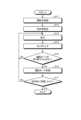
次に、上述した自動運転レベルを踏まえて、図2を参照して、本開示の実施形態に係る走行の例について説明する。図2は、本開示の実施形態に係る走行の一例を説明するためのフローチャートである。図2に示すように、本開示の実施形態に係る走行においては、車両制御システムは、例えば、ステップS11からステップS17までのステップを実行することとなる。以下に、これら各ステップの詳細について説明する。 <<2. Examples of driving>>
Next, in consideration of the above-mentioned autonomous driving levels, an example of driving according to the embodiment of the present disclosure will be described with reference to Fig. 2. Fig. 2 is a flowchart for explaining an example of driving according to the embodiment of the present disclosure. As shown in Fig. 2, in the driving according to the embodiment of the present disclosure, the vehicle control system executes steps from step S11 to step S17, for example. Each of these steps will be described in detail below.
まず、車両制御システムは、運転手認証を実行する(ステップS11)。当該運転手認証は、パスワードや暗証番号等による知識認証、あるいは顔、指紋、瞳の虹彩、声紋等による生体認証、さらには知識認証と生体認証とが併用されて行われることができる。本開示の実施形態においては、走行を開始する前に、このような運転手認証が実行されることにより、複数の運転手が同一の車両を運転する場合であっても、各運転手の眼球挙動等といった各運転手に特徴的な生体情報等を各運転手に紐づけて取得することが可能となる。First, the vehicle control system performs driver authentication (step S11). The driver authentication can be performed by knowledge authentication using a password or a PIN number, or biometric authentication using a face, fingerprint, iris, voiceprint, or the like, or by a combination of knowledge authentication and biometric authentication. In an embodiment of the present disclosure, such driver authentication is performed before starting driving, so that even if multiple drivers drive the same vehicle, biometric information characteristic of each driver, such as eye behavior, can be associated with each driver and acquired.
次に、運転手等により例えば後述する入力部101(図5 参照)が操作されることにより、目的地が設定される(ステップS12)。なお、ここでは、車両に乗車して目的地の設定を行う例を説明したが、本開示の実施形態においてはこれに限定されるものではなく、車両制御システムは、車両に乗車する前にスマートフォン等(車両制御システムと通信可能であるものとする)に手入力された目的地情報やカレンダ情報に基づき、目的地を事前設定してもよい。もしくは、車両制御システムは、事前にスマートフォン等やクラウドサーバ等(車両制御システムと通信可能であるものとする)に格納されたスケジュール情報等を、コンセルジュサービスを介して取得することにより、自動的に目的地を事前設定してもよい。そして、車両制御システムは、設定された目的地に基づき、走行ルート等のプリプラニング設定を行う。さらに、車両制御システムは、設定した走行ルートの道路環境の情報等、すなわち車両が走行する道路の走行地図情報が高密度に常時更新されたものであるローカルダイナミックマップ(LDM)情報等を更新取得することとなる。加えて、車両制御システムは、取得したLDM情報等に基づき、走行ルート上の各区間に適切な自動運転レベルを設定する。Next, the destination is set by the driver or the like operating the input unit 101 (see FIG. 5 ), which will be described later (step S12). Here, an example in which the destination is set by getting into the vehicle has been described, but the embodiment of the present disclosure is not limited to this. The vehicle control system may pre-set the destination based on destination information and calendar information manually input into a smartphone or the like (which is assumed to be capable of communicating with the vehicle control system) before getting into the vehicle. Alternatively, the vehicle control system may automatically pre-set the destination by acquiring schedule information stored in advance in a smartphone or the like or a cloud server or the like (which is assumed to be capable of communicating with the vehicle control system) via a concierge service. Then, the vehicle control system performs pre-planning setting of the driving route, etc., based on the set destination. Furthermore, the vehicle control system updates and acquires information on the road environment of the set driving route, i.e., local dynamic map (LDM) information, which is constantly updated with high density driving map information of the road on which the vehicle travels. In addition, the vehicle control system sets an appropriate autonomous driving level for each section on the driving route based on the acquired LDM information, etc.
次に、車両制御システムは、走行ルート上の走行区間表示を開始する。そして、車両制御システムは、設定した自動運転レベルに従って、走行を開始する(ステップS13)。なお、走行が開始されると、車両(自車)の位置情報と取得したLDM更新情報に基づいて、走行区間の表示が更新されていくこととなる。Next, the vehicle control system starts displaying the driving section on the driving route. The vehicle control system then starts driving according to the set autonomous driving level (step S13). When driving starts, the display of the driving section is updated based on the vehicle's (own vehicle's) position information and the acquired LDM update information.
次に、車両制御システムは、運転手の状態のモニタリング(観測)を適宜実行する(ステップS14)。本開示の実施形態においては、当該モニタリングは、例えば、運転手の復帰対応レベル(例えば、覚醒レベル)を判定するための教師データを取得するために実行されたり、走行ルート上の各区間に設定された自動運転レベルに従って運転モードを切り替えるために実行されたりすることとなる。なお、当該モニタリングの詳細については後述する。Next, the vehicle control system appropriately monitors (observes) the driver's state (step S14). In an embodiment of the present disclosure, the monitoring is performed, for example, to obtain teacher data for determining the driver's recovery response level (e.g., alertness level) or to switch the driving mode according to the autonomous driving level set for each section on the driving route. The details of the monitoring will be described later.
次に、車両が、走行ルート上の各区間に設定された自動運転レベルに基づく自動運転モードから手動運転モードへの切り替え地点に到達した場合には、車両制御システムは、運転モードを切り替えることができるかどうかの判定を行う(ステップS15)。なお、この際に行われる判定の詳細については後述する。そして、車両制御システムは、運転モードを切り替えることができると判定した場合(ステップS15:Yes)には、ステップS16の処理へ進み、運転モードを切り替えることができないと判定した場合(ステップS15:No)には、ステップS13の処理へ戻る。Next, when the vehicle reaches a switching point from the autonomous driving mode to the manual driving mode based on the autonomous driving level set for each section on the driving route, the vehicle control system determines whether the driving mode can be switched (step S15). Details of the determination made at this time will be described later. Then, if the vehicle control system determines that the driving mode can be switched (step S15: Yes), it proceeds to the processing of step S16, and if it determines that the driving mode cannot be switched (step S15: No), it returns to the processing of step S13.
次に、車両制御システムは、運転モードを切り替える(ステップS16)。さらに、車両制御システムは、車両(自車)が目的地に到着したかどうかの判定を行う(ステップS17)。車両制御システムは、車両が目的地に到着した場合(ステップS17:Yes)には、処理を終了し、自車が目的地に到着していない場合(ステップS17:No)には、ステップS13の処理へ戻る。以降、車両制御システムは、車両が目的地に到着するまで、ステップS13からステップS17までの処理を適宜繰り返すこととなる。Next, the vehicle control system switches the driving mode (step S16). Furthermore, the vehicle control system determines whether the vehicle (own vehicle) has arrived at the destination (step S17). If the vehicle has arrived at the destination (step S17: Yes), the vehicle control system ends the process, and if the own vehicle has not arrived at the destination (step S17: No), the vehicle control system returns to the process of step S13. Thereafter, the vehicle control system appropriately repeats the processes from step S13 to step S17 until the vehicle arrives at the destination.
<<3. 自動運転レベルの遷移の例について>>
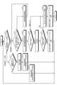
次に、図3を参照して、さらに詳細に、本開示の実施形態に係る自動運転レベルの遷移の例について説明する。図3は、本開示の実施形態に係る自動運転レベルの遷移の一例を説明するための説明図である。 <<3. Examples of transitions in autonomous driving levels>>
Next, an example of a transition of an autonomous driving level according to an embodiment of the present disclosure will be described in more detail with reference to Fig. 3. Fig. 3 is an explanatory diagram for explaining an example of a transition of an autonomous driving level according to an embodiment of the present disclosure.
図3に示すように、自動運転モード(図3中の下側の範囲)から手動運転モード(図3中の上側の領域)への切り替えは、例えば、走行ルート上の自動運転レベル3及び自動運転レベル4の区間から、自動運転レベル0、1及び自動運転レベル2の区間へと遷移する際に実行されると想定される。As shown in Figure 3, switching from autonomous driving mode (lower area in Figure 3) to manual driving mode (upper area in Figure 3) is assumed to be performed, for example, when transitioning from
ところで、自動運転モードで走行している間、運転手が手動運転に復帰できる準備状態を意識して維持することは難しい。例えば、自動運転モードで走行している間、運転手は、睡眠(仮眠)や、テレビやビデオの視聴、あるいはゲーム等の2次タスクに没頭することが考えられる。また、例えば、運転手は、ハンドルから手を放しているのみで、手動運転時と同様、自動車の前方や周囲を注視している場合もあり、本を読んでいる場合もあり、また、居眠りをしている場合もある。そして、これらの2次タスクの違いにより、運転手の覚醒レベル(意識レベル)は異なるものとなる。However, it is difficult for the driver to consciously maintain a state of readiness to return to manual driving while driving in autonomous driving mode. For example, while driving in autonomous driving mode, the driver may be immersed in secondary tasks such as sleeping (taking a nap), watching television or videos, or playing games. In addition, for example, the driver may simply take their hands off the steering wheel and gaze at the front or surroundings of the vehicle, just as when driving manually, or may be reading a book, or may even be dozing off. Depending on these differences in secondary tasks, the driver's level of alertness (level of consciousness) will differ.
さらに、自動運転モードで走行している間において睡眠に陥ると、運転手の意識レベルや判断レベルが低下した状態、すなわち覚醒レベルが低下した状態になる。そして、覚醒レベルが低下した状態では、運転手は正常な手動運転を行うことができないことから、その状態で手動運転モードに切り替えた場合、最悪の場合、事故を起こす可能性がある。そこで、運転手は、覚醒レベルが低下した状態であっても、手動運転モードへの切り替える直前には、正常な意識下で車両を運転できる高い覚醒状態に復帰していること(内部覚醒復帰状態)が求められることとなる。すなわち、安全走行を確保するためには、自動運転モードから手動運転モードへの切り替えは、運転手の内部覚醒状態が復帰した状態にあることが観測できた場合にのみ実行することが求められることとなる。Furthermore, if a driver falls asleep while driving in autonomous driving mode, the driver's level of consciousness and judgment is reduced, i.e., the driver's level of alertness is reduced. With a reduced level of alertness, the driver is unable to drive normally, and in the worst case scenario, switching to manual driving mode in this state could result in an accident. Therefore, even if the driver's level of alertness is reduced, the driver is required to return to a high level of alertness in which he or she can drive the vehicle with normal consciousness (internal alertness return state) immediately before switching to manual driving mode. In other words, to ensure safe driving, switching from autonomous driving mode to manual driving mode is required to be performed only when it is observed that the driver's internal alertness has returned.
そこで、本開示の実施形態においては、このような運転モードの切り替えは、事故等の誘発を避けるべく、運転手が手動運転モードへの復帰対応レベルにあること、すなわち、内部覚醒復帰(運転手の内部覚醒状態が復帰した状態)を示すアクティブな応答を観測できた場合(図3中の中央に示す)にのみ、実行することができるものとする。また、本開示の実施形態においては、図3に示すように、内部覚醒復帰を示すアクティブな応答を観測できない場合には、MRM(Minimal Risk Maneuver)等の緊急退避モードへ切り替えることとなる。なお、緊急退避モードにおいては、減速、停止、道路、路側帯又は退避スペースへの駐車等の処理を行う。また、図3においては、自動運転レベル4から自動運転レベル3への遷移については、運転モードの切り替えが伴わないことから、上述したような内部覚醒復帰を示すアクティブな応答の観測自体を行っていない。しかしながら、本実施形態においては、図3に示すような例に限定されるものではなく、自動運転レベル4から自動運転レベル3への遷移においても、上述のような観測や観測結果に基づく遷移を行ってもよい。Therefore, in the embodiment of the present disclosure, such driving mode switching can be performed only when the driver is at a level capable of returning to the manual driving mode in order to avoid the induction of an accident, that is, when an active response indicating internal arousal return (a state in which the driver's internal arousal state has returned) can be observed (as shown in the center of FIG. 3). In addition, in the embodiment of the present disclosure, as shown in FIG. 3, if an active response indicating internal arousal return cannot be observed, the vehicle is switched to an emergency evacuation mode such as MRM (Minimal Risk Maneuver). In addition, in the emergency evacuation mode, processing such as deceleration, stopping, parking on a road, a roadside strip, or an evacuation space is performed. In addition, in FIG. 3, the transition from
詳細には、自動運転レベル4から自動運転レベル3への遷移を行う際に内部覚醒復帰を示すアクティブな応答が観測されない場合、運転手が法制度により手動運転への復帰義務を負うべきものだとしても、運転手が、車両制御システムからの自動運転レベル3としての復帰要請RTI(Request to Intervene)に対して適切に対応できる状態とは限らない。より具体的には、自動運転レベル3としての復帰要請RTIに対して、運転手が、脳内覚醒状態が復帰した状態にあり、且つ、身体にしびれ等がない手動運転可能な身体状態に復帰できるとは限らない。このような場合に自動運転レベル4から自動運転レベル3への遷移を行うと、車両制御システムにおいて事前に想定された設計思想を超えた状況に及ぶ恐れがあり、事故等の誘発する可能性がある。そこで、以下の本実施形態においては、上述のような可能性を減らすために、車両制御システム側が運転手に対して復帰要請RTIを発する必要がない段階であっても、運転手の復帰対応レベル(例えば、覚醒レベル)を確認するために、予防的なダミーの復帰要請RTIを適宜行い、運転手の内部覚醒復帰を示すアクティブな応答を観測してもよい。In detail, if an active response indicating a return of internal alertness is not observed when transitioning from
なお、図3で図示した自動運転レベルの遷移を示す各矢印は、自動で切り替えを行うことが許容された遷移の方向を示すものであり、さらに、各矢印の逆方向の遷移は、運転手による車両制御システムの状態に対する誤認を招くものであるとして、推奨されるものではない。すなわち、本開示の実施形態に係る車両制御システムにおいては、自動運転モードから自動で、運転手が介在する手動運転モードへ切り替わるような自動運転レベルの遷移がひとたび行われた場合、運転手の意図的指示がないまま再び自動運転モードへ自動的に戻ることがないように設計されていることが望ましい。このように、運転モードの切り替えに方向性(不可逆性)を持たせることは、運転手の明確な意図がないまま自動運転モードとすることを防ぐ設計となっていることを意味する。従って、当該車両制御システムによれば、運転手が明確な意図を持ってのみ自動運転モードが有効化できないことから、例えば、運転手が、自動運転モードではないときに、自動運転モードであると勘違いして安易に2次タスクを始める等の行為を防止することができる。Note that each arrow showing the transition of the autonomous driving level illustrated in FIG. 3 indicates the direction of the transition that is permitted to be performed automatically, and furthermore, transitions in the opposite direction of each arrow are not recommended as they may lead to the driver misunderstanding the state of the vehicle control system. That is, in the vehicle control system according to the embodiment of the present disclosure, once an autonomous driving level transition such as switching from the autonomous driving mode to a manual driving mode in which the driver is involved is performed automatically, it is desirable to design the system so that it does not automatically return to the autonomous driving mode without the driver's intentional instruction. In this way, giving directionality (irreversibility) to the switching of the driving mode means that the system is designed to prevent the autonomous driving mode from being set without the driver's clear intention. Therefore, according to the vehicle control system, the autonomous driving mode cannot be enabled unless the driver has a clear intention, so that, for example, the driver can be prevented from easily starting a secondary task by mistakenly thinking that the autonomous driving mode is in the autonomous driving mode when it is not in the autonomous driving mode.
以上のように、本開示の実施形態においては、安全走行を確保するために、自動運転モードから手動運転モードへの切り替えは、運転手が内部復帰状態であることが観測できた場合にのみ実行する。As described above, in an embodiment of the present disclosure, in order to ensure safe driving, switching from autonomous driving mode to manual driving mode is performed only when it is observed that the driver is in an internal return state.
<<4. モニタリングの例について>>
そこで、図4を参照して、自動運転モードから手動運転モードへの切り替えの際のモニタリング(観測)の例について説明する。図4は、本開示の実施形態に係るモニタリング動作の一例を説明するフローチャートである。図4に示すように、本開示の実施形態においては、車両制御システムは、例えば、自動運転モードから手動運転モードへの切り替えの際には、ステップS21からステップS27までのステップを実行することとなる。以下に、これら各ステップの詳細について説明する。 <<4. Examples of monitoring>>
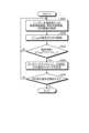
An example of monitoring (observation) when switching from the autonomous driving mode to the manual driving mode will be described with reference to Fig. 4. Fig. 4 is a flowchart illustrating an example of a monitoring operation according to an embodiment of the present disclosure. As shown in Fig. 4, in the embodiment of the present disclosure, the vehicle control system executes steps S21 to S27 when switching from the autonomous driving mode to the manual driving mode, for example. Each of these steps will be described in detail below.
まず、運転手は、自動運転モードでの走行中であるため、運転操舵から完全離脱の状態にあるものとする。さらに、運転手は、例えば、仮眠、あるいはビデオ鑑賞、没頭してゲームする、タブレット、スマートフォン等の視覚ツールを用いた作業等の2次タスクを実行しているものとする。ただし、タブレット、スマートフォン等の視覚ツールを用いた作業は、例えば、運転席をずらした状態で、あるいは運転席とは別の席で行うことも想定されるものとする。First, the driver is assumed to be completely detached from driving and steering since the vehicle is being driven in autonomous driving mode. Furthermore, the driver is assumed to be performing secondary tasks such as, for example, napping, watching videos, engrossed in playing games, or working with visual tools such as a tablet or smartphone. However, it is also assumed that working with visual tools such as a tablet or smartphone may be performed with the driver's seat shifted or in a seat other than the driver's seat.
まず、車両制御システムは、運転手に対してパッシブモニタリング、及び/又は、アクティブモニタリングを適宜間欠的に実行する(ステップS21)。ここで、アクティブモニタリング及びパッシブモニタリングについて説明する。First, the vehicle control system performs passive monitoring and/or active monitoring of the driver intermittently as appropriate (step S21). Here, we will explain active monitoring and passive monitoring.
まずは、アクティブモニタリングとは、運転手の主に知能的な知覚・認知・判断・行動の能力判定を行うため、車両制御システムが、能動的情報を運転手に対して入力し、それに対する運転手の意識的な応答を見る観測方法である。例えば、運転手に対して入力する能動的情報としては、視覚、聴覚、触覚、臭覚、(味覚)情報を挙げることができる。これらの能動的情報は、運転手の知覚と認知行動とを誘発し、リスクに影響する情報であればそのリスクに応じて運転手が判断・行動を実行(応答)することとなることから、このような運転手の応答を観測することにより、運転手の脳内の知覚・認知・判断・行動状態を判定することが可能となる。具体的には、アクティブモニタリングにおいては、例えば、車両制御システムが運転手のフィードバックを促すために疑似的に能動的情報として車両の安全走行に影響を及ぼさない程度の僅かな操舵量でのステアリング制御を実行した場合、運転手がステアリングを適切な操舵量に戻す行為が(正常に覚醒していれば)意識的な応答として期待される(詳細には、運転手は、不必要な操舵量を知覚、認知し、不必要な操舵量に対して戻す判断、行動を起こすという一連の動作を行っているため上記応答に対応する行為が引き出される。従って、上記応答を観測することにより、運転手の脳内の知覚・認知・判断・行動状態を判定する可能となる)。なお、手動運転モードでの走行中は、運転手は、操舵の実行のために、道路環境等に対する知覚・認知・判断・行動の一連の動作を常時行っているため、車両制御システム側が直接的に運転手に対して能動的情報の入力を行わなくとも、運転手の意識的な応答を観測することができる(すなわち、運転操舵という応答があるといえる)。さらに、上述のような能動的情報入力を繰り返し行った場合、これらの情報は、運転手の脳内で知能的にフィルタリングされ、不要なものとして扱われるようになるため(すなわち「慣れ」)、本開示の実施形態においては、能動的情報入力の頻度は、上述のような「慣れ」を避けるべく、適切な頻度に設定されることが好ましい。First of all, active monitoring is an observation method in which the vehicle control system inputs active information to the driver and observes the driver's conscious response to it in order to determine the driver's abilities, mainly intellectual perception, cognition, judgment, and action. For example, active information input to the driver can include visual, auditory, tactile, olfactory, and (gustatory) information. This active information induces the driver's perception and cognitive behavior, and if the information affects risk, the driver will make judgments and take action (respond) in accordance with that risk. Therefore, by observing the driver's responses, it is possible to determine the perceptual, cognitive, judgment, and action states in the driver's brain. Specifically, in active monitoring, for example, when the vehicle control system executes steering control with a slight steering amount that does not affect the safe driving of the vehicle as pseudo-active information to encourage the driver's feedback, the driver is expected to return the steering to an appropriate steering amount (if he is normally awake) as a conscious response (in detail, the driver performs a series of actions of perceiving and recognizing an unnecessary steering amount, and making a decision and taking an action to return the unnecessary steering amount, so that an action corresponding to the above response is elicited. Therefore, by observing the above response, it is possible to determine the perception, recognition, judgment, and behavior state in the driver's brain). Note that, during driving in manual driving mode, the driver always performs a series of actions of perception, recognition, judgment, and behavior with respect to the road environment, etc., in order to execute steering, so that the conscious response of the driver can be observed even if the vehicle control system does not directly input active information to the driver (i.e., it can be said that there is a response of driving and steering). Furthermore, if active information input as described above is repeated, the information will be intelligently filtered in the driver's brain and treated as unnecessary (i.e., "habituation"), so in the embodiments of the present disclosure, it is preferable that the frequency of active information input be set to an appropriate frequency to avoid the above-mentioned "habituation."
次に、パッシブモニタリングとは、直接的な能動的情報入力に対する運転手の意識的な応答を観測(アクティブモニタリング)できない場合等に実行される。運転手の状態のパッシブモニタリングには多様な観測手法があり、例えば、運転手の生体情報の観測を挙げることができる。より具体的には、例えば、パッシブモニタリングにおいては、運転席に着座し、且つ、運転可能な姿勢であれば、PERCLOS(開眼割合)関連指標、頭部姿勢挙動、眼球挙動(サッカード(急速性眼球運動)、固視、マイクロサッカード等)、瞬き、顔の表情、顔の向き等の詳細観測評価を行うことが期待される。さらに、着座以外の姿勢においては、ウェアブルデバイス等を用いることにより、心拍数、脈拍数、血流、呼吸、脳波、発汗状態、心拍数及び呼吸から推定される眠気の深さ等を観測する拡張観測が可能である。さらに、パッシブモニタリングにおいては、運転手の運転席への着座や離席、移動、移動先、姿勢等を観測してもよい。さらに、運転手の注意運転状態(運転に対して適切な注意を維持しながら手動運転を行っている状態)と関連する操舵量を直接的に観測してもよい。また、パッシブモニタリングで観測された情報は、自動運転モード走行中に、運転制御システム側が、運転モードの切り替え通知や警報等を出した場合、運転手が手動運転に復帰する際に要する時間を推定するために使用することができる。さらに、パッシブモニタリングで観測された情報は、所定の時間内で運転手が手動運転に復帰することが望めない場合に緊急退避モードへの切り替えの有無を判定するために使用したりすることができる。Next, passive monitoring is performed when the driver's conscious response to direct active information input cannot be observed (active monitoring). There are various observation methods for passive monitoring of the driver's state, such as observing the driver's biological information. More specifically, for example, in passive monitoring, if the driver is seated in the driver's seat and in a driving position, it is expected that detailed observation and evaluation will be performed on PERCLOS (percentage of eyes open) related indicators, head posture behavior, eye behavior (saccades (rapid eye movement), fixation, microsaccades, etc.), blinking, facial expression, face direction, etc. Furthermore, in positions other than sitting, extended observation is possible by using wearable devices, etc., to observe heart rate, pulse rate, blood flow, breathing, brain waves, sweating state, depth of drowsiness estimated from heart rate and breathing. Furthermore, in passive monitoring, the driver's sitting in and leaving the driver's seat, movement, destination, posture, etc. may be observed. Furthermore, the steering amount associated with the driver's attention driving state (the state in which the driver is driving manually while maintaining appropriate attention to driving) may be directly observed. Information observed by passive monitoring can also be used to estimate the time required for the driver to return to manual driving when the driving control system issues a driving mode switching notification or warning during autonomous driving mode driving. Furthermore, information observed by passive monitoring can be used to determine whether or not to switch to emergency evacuation mode when it is not expected that the driver will return to manual driving within a predetermined time.
次に、図4に戻り説明を続ける。車両制御システムは、運転手に対して手動運転への復帰要請RTIを通知する(ステップS22)。この際、例えば、運転手に対して、振動等の動的なハプティックスや視覚的あるいは聴覚的に手動運転への復帰要請RTIが通知される。そして、このような復帰要請RTIの通知に応じて、運転手は、正常な覚醒状態であれば運転席に戻り、正常な意識下で車両を運転できる高い覚醒状態に復帰することとなる。なお、復帰要請RTIは、段階的に複数回行われてもよく、この場合、各段階で異なる手段で行われてもよく、例えば運転手の状態等に応じて動的に変化させてもよい。Next, let us return to FIG. 4 for further explanation. The vehicle control system notifies the driver of a request RTI to return to manual driving (step S22). At this time, for example, the driver is notified of the request RTI to return to manual driving by dynamic haptics such as vibration, or visually or audibly. Then, in response to such notification of the return request RTI, if the driver is in a normal state of alertness, he or she will return to the driver's seat and return to a high state of alertness in which the driver can drive the vehicle with normal consciousness. The return request RTI may be performed multiple times in stages, and in this case, may be performed by different means at each stage, and may be dynamically changed according to, for example, the driver's state, etc.
次に、車両制御システムは、運転手の着席状態や、着席の姿勢等をモニタリングする(ステップS23)。さらに、車両制御システムは、適切に着席した運転手に対してアクティブモニタリングを集中的に実行する(ステップS24)。例えば、アクティブモニタリングとしては、運転手に対して、正常な意識下で車両を運転できる高い覚醒状態に復帰することを促すために、運転手に対して警告等を行ったり、疑似的に車両の手動操舵制御に疑似ノイズ操舵を入力したりするような、能動的な情報入力を行うことが挙げられる。Next, the vehicle control system monitors the driver's seating state, seating posture, etc. (step S23). Furthermore, the vehicle control system intensively performs active monitoring on the driver who is properly seated (step S24). For example, active monitoring may include active information input, such as issuing a warning to the driver or inputting pseudo-noise steering into the manual steering control of the vehicle, to encourage the driver to return to a high state of alertness in which the driver can drive the vehicle with normal consciousness.
次に、車両制御システムは、運転手の顔やサッカード等の眼球挙動を集中的にモニタリング(眼球挙動集中モニタリング)する(ステップS25)。Next, the vehicle control system intensively monitors the driver's face and eye behavior such as saccades (intensive eye behavior monitoring) (step S25).
ここで、眼球挙動のモニタリングについて説明する。運転手の状態の情報は様々な手段で観測することが可能であるが、運転手の脳内の認知・判断行動を直接的に観測することは難しい。例えば、fMRI(functional Magnetic Resonance Imaging)や脳波計(Electroencephalogram:EEG)等を使用する場合には、被観測者(運転手)を拘束することが求められることから、本開示の実施形態において運転手の状態を観測する手段としては好適なものではない。そこで、本開示の実施形態においては、様々な生体情報観測手段の1つとして、運転手の眼球挙動を観測する手段を用いる。眼球挙動観測は、例えば、運転手が運転席に着座していれば、運転手を特別に拘束することなく実行することが可能である。すなわち、眼球挙動観測は、非侵襲、且つ、非装着型の観測手段であるといえる。Here, monitoring of eye behavior will be described. Information on the driver's state can be observed by various means, but it is difficult to directly observe the driver's cognitive and judgmental behavior in the brain. For example, when using functional magnetic resonance imaging (fMRI) or electroencephalogram (EEG), etc., it is necessary to restrain the observed person (driver), so it is not suitable as a means for observing the driver's state in the embodiment of the present disclosure. Therefore, in the embodiment of the present disclosure, a means for observing the driver's eye behavior is used as one of various biological information observation means. Eye behavior observation can be performed, for example, as long as the driver is seated in the driver's seat, without special restraint of the driver. In other words, eye behavior observation can be said to be a non-invasive and non-wearable observation means.
また、眼球挙動は、生体反射的に現れる挙動が一部あり、視覚相対移動物を追いかけるスムースパーシュート(滑動性追跡眼球運動)や車両の進行先進の背景接近で起こる緩やかの輻輳とその復帰高速開散運動、自身の身体・頭部の回転を打ち消し対象方角のものを追う滑動性追跡眼球運動等、事象変化に対する応答が思考的な要素を含まないループに対し、適応応答調整して現れる反応と、反射的な応答ではなく、視覚対象の特徴を捉えて理解を進めるために特徴追跡する挙動が、特徴的なマイクロサッカード等が固視に発現する際に起きる。これら挙動には、脳内の神経伝達と処理とを反映して現れる多くの現象も同時に見られる。つまり、脳の記憶に参照した固視対象の認知等の活動結果が反映されていると考えられる。従って、眼球挙動に脳内の認知機能活動が反映されることを利用することにより、眼球挙動の解析に基づき、運転手の覚醒レベルを高精度で推測することが可能となる。すなわち、眼球挙動観測を実行することにより、自動運転モードから手動運転モードへの切り替えの際(詳細には、その直前)に、運転手が正常な意識下で車両を運転できる高い覚醒レベルに復帰しているかどうか(復帰対応レベル)を間接的に観測することができる。特に、運転手は、一旦運転操舵作業から離れて時間が経過してから運転操舵に復帰をする場合には、手動運転への復帰のために必要な周囲や車両状態の記憶を十分に持ち合わせていないと考えらえる。そこで、運転手は、例えば、道路前方の状況を目視確認したり、車両制御システムからの手動運転への復帰要請RTIの要因を目視確認したりと、運転手が継続的な手動運転を行っていた場合には把握しているだろう情報を把握するための行為を早急に進めようとすることとなる。そして、このような情報把握行為は、運転手の眼球挙動に反映されることとなる。In addition, some eye behaviors appear as biological reflexes, such as smooth pursuit eye movement to pursue a visually relative moving object, the gradual convergence and rapid return divergence that occurs when the vehicle approaches the background ahead of the vehicle, and smooth pursuit eye movement to pursue an object in the target direction while countering the rotation of the body and head. In response to changes in events, there are reactions that appear as adaptive responses to loops that do not include a thought element, and behaviors that are not reflexive responses but rather follow the characteristics of a visual object to advance understanding, which occur when characteristic microsaccades and the like are expressed in fixation. Many phenomena that reflect neural transmission and processing in the brain are also seen at the same time in these behaviors. In other words, it is thought that the results of activities such as recognition of the fixation object referenced in the brain's memory are reflected. Therefore, by utilizing the fact that eye behavior reflects cognitive function activity in the brain, it is possible to estimate the driver's alertness level with high accuracy based on the analysis of eye behavior. That is, by performing eye behavior observation, it is possible to indirectly observe whether the driver has returned to a high level of awareness (return response level) at the time of switching from the automatic driving mode to the manual driving mode (specifically, immediately before the switching). In particular, when the driver returns to the driving and steering operation after a period of time has elapsed after once leaving the driving and steering operation, it is considered that the driver does not have sufficient memory of the surroundings and vehicle state required for returning to manual driving. Therefore, the driver will try to quickly proceed with actions to grasp information that the driver would have grasped if the driver had been continuously driving manually, such as visually checking the situation on the road ahead or visually checking the cause of the request RTI to return to manual driving from the vehicle control system. Then, such actions of grasping information are reflected in the driver's eye behavior.
さらに、先に説明したように、眼球挙動は、人物ごとに、さらにその人物の状態ごとに、特有の挙動を示すことから、眼球挙動を解析することにより運転手の覚醒レベルを精度よく判定しようとする場合には、個々の運転手特有の眼球挙動を、常に把握、学習し、このような学習に基づいて、運転手の覚醒レベルを判定することが求められる。さらに、手動運転への復帰の際に、運転手が、何を重点的に確認するか、どのような優先順位に従って確認を行うかについては、当該運転手の過去のリスク体験等に基づく記憶にも大きく影響されることから、走行中の道路状況や走行速度等の多様な要因により変化する。従って、眼球挙動は、人物ごとに特有の挙動を示すだけでなく、運転手の様々な体験に基づく記憶から影響を受けて、変化することとなる。本実施形態においては、ドライバー人口に対して一律の判定を用いて覚醒度判定を行うのではなく、同一運転手の復帰能力判定を、能動的観測区間に間欠学習して得られた学習に基づいて行うことから、運転手ごとにより好適に判定を行うことを可能にする。Furthermore, as explained above, eye behavior shows unique behavior for each person and for each state of the person, so when trying to accurately determine the driver's alertness level by analyzing eye behavior, it is necessary to constantly grasp and learn the eye behavior unique to each driver and determine the driver's alertness level based on such learning. Furthermore, when returning to manual driving, what the driver will focus on checking and the priority of checking are greatly influenced by the driver's memory based on past risk experiences, etc., and therefore change depending on various factors such as the road conditions and driving speed during driving. Therefore, eye behavior not only shows unique behavior for each person, but also changes due to the influence of memories based on the driver's various experiences. In this embodiment, the alertness level is not determined using a uniform determination for the driver population, but the return ability of the same driver is determined based on learning obtained by intermittent learning in active observation sections, making it possible to make a more suitable determination for each driver.
そして、車両制御システムは、上述のステップS25でのモニタリングに基づき、運転手の覚醒レベルを判定することにより、運転手の復帰対応レベルを判定する(ステップS26)。そして、車両制御システムは、運転手が手動運転への復帰対応が可能な復帰反応レベルにあるかを判定する。本実施形態に係る車両制御システムは、運転手の復帰過程を段階的に観測し、その途中の各段階の運転手の応答を観測しているため、複合的な判定が可能である。そして、車両制御システムは、運転手の内部覚醒復帰、手動運転行動の能力確認に基づき、所定の確度をもって手動運転への復帰が可能と判定した場合、自動運転モードから手動運転モードへの切り替えを実行する(ステップS27)。The vehicle control system then determines the driver's level of readiness for return by determining the driver's level of alertness based on the monitoring in step S25 described above (step S26). The vehicle control system then determines whether the driver is at a level of readiness for return to manual driving. The vehicle control system according to this embodiment observes the driver's return process in stages and observes the driver's response at each stage along the way, making it possible to make a composite judgment. If the vehicle control system determines that return to manual driving is possible with a certain degree of certainty based on the driver's internal alertness return and ability confirmation of manual driving behavior, it executes a switch from automatic driving mode to manual driving mode (step S27).
なお、図4の各ステップは、必ずしも記載された順序に沿って処理されなくてもよく、適宜順序が変更されて処理されてもよく、一部並列的に処理されてもよい。例えば、ステップS24のアクティブモニタリングと、ステップS25の眼球挙動集中モニタリングは、並列的に実施されてもよく、もしくは、図4に示す順序を入れ替えて処理してもよい。Note that the steps in FIG. 4 do not necessarily have to be processed in the order described, but may be processed in a different order as appropriate, or may be partially processed in parallel. For example, the active monitoring in step S24 and the intensive eye behavior monitoring in step S25 may be performed in parallel, or may be processed in the order shown in FIG. 4 interchangeably.
<<5. 本開示の実施形態を創作するに至る背景>>
さらに、本開示の実施形態の詳細を説明する前に、本発明者らが本開示の実施形態を創作するに至る背景について説明する。 <<5. Background leading to the creation of the embodiments of the present disclosure>>
Furthermore, before describing the details of the embodiments of the present disclosure, the background that led the inventors to create the embodiments of the present disclosure will be described.
ところで、運転手が仮眠や離席状態から運転席に戻り、実際にハンドルを握って手動運転を主体的に行う間には複数の復帰過程や段階があり、理想的には段階を経るごとに運転手の復帰対応レベル(覚醒レベル)が上昇することとなる。そして、車両制御システムにおいては、理想的に運転手の復帰対応レベルが上昇する状況ではない場合であっても、復帰過程や段階に応じて、様々な運転手の内部覚醒復帰、手動運転行動の能力確認のための確認手段を用いることができる。例えば、運転手が車内の仮眠所での仮眠や離席して仮眠をしていた状態からの復帰の場合、睡眠状態からの復帰を示す応答としての体の動きとして、仮眠姿勢から運転席への復帰のための姿勢変化、足による立ち上がり、席の移動等を検出することにより、運転手の内部覚醒復帰、手動運転行動の能力確認を行うことができる。また、TV会議等のために離席した状態での作業状態からの復帰の場合、運転席への着座や、離席した状態での車両制御システムからの復帰要請RTIへの確認応答動作や運転席への復帰の移動行動等を検出することにより、運転手の内部覚醒復帰、手動運転行動の能力確認を行うことができる。さらに、運転手が運転席付近に達した場合、運転手による、道路前方確認動作、必要があれば道路前方の指差呼称確認動作、運転席での運転姿勢への変化及びそれに伴う足の移動、前方確認動作に伴う頭部や顔の向き等を検出することにより、運転手の内部覚醒復帰、手動運転行動の能力確認を行うことができる。また、運転手による、車両制御システムからの復帰要請RTIに対する目視確認、復帰要請RTIに伴うメッセージ内容や完全復帰完了時間等を確認するための視線移動(眼球挙動)等を検出することによっても、運転手の内部覚醒復帰、手動運転行動の能力確認を行うことができる。さらに、手動運転を開始する際の、運転手による、車両周辺状況を確認するための視線移動(眼球挙動)や、自動運転解除スイッチ類に対する操作、段階的なステアリングハンドルのトルク挿入、ブレーキペダルへの押圧アクション、アクセルペダルへの押圧アクション、加速指示及び減速指示、車両制御システムから注入された操舵方角に関する仮想的ノイズに対する補正動作等を検出することによっても、運転手の内部覚醒復帰、手動運転行動の能力確認を行うことができる。すなわち、車両制御システムは、運転手の復帰過程における復帰対応レベルを段階的に、且つ、複合的に観測することが求められる。そして、このような、段階的、且つ、複合的な観測の最終段階において、運転手の脳内の認知・判断行動のレベルを推定するための1つの手段として、高いフレームレートでの眼球挙動のサンプリング、解析を行うこととなる。By the way, there are multiple recovery processes and stages between when a driver returns to the driver's seat from a nap or when he/she has left the seat, and when he/she actually holds the steering wheel and performs manual driving independently. Ideally, the driver's recovery response level (wakefulness level) increases with each stage. In the vehicle control system, even if the driver's recovery response level does not ideally increase, various confirmation means for the driver's internal wakefulness recovery and manual driving behavior ability confirmation can be used according to the recovery process and stage. For example, when a driver returns from a nap in a sleeping area in the vehicle or from a state where he/she has left the seat and taken a nap, the driver's internal wakefulness recovery and manual driving behavior ability confirmation can be performed by detecting a change in posture from a nap position to return to the driver's seat, standing up with the feet, moving the seat, etc., as body movements in response to the return from a sleep state. In addition, when returning from a working state in which the driver has left his/her seat for a TV conference or the like, the driver's internal awakening return and the ability to perform manual driving actions can be confirmed by detecting the driver's sitting in the driver's seat, the confirmation response action to the return request RTI from the vehicle control system when the driver has left the seat, the movement action of returning to the driver's seat, etc. Furthermore, when the driver reaches the vicinity of the driver's seat, the driver's internal awakening return and the ability to perform manual driving actions can be confirmed by detecting the driver's action of checking the road ahead, the pointing and calling confirmation action on the road ahead if necessary, the change in driving posture in the driver's seat and the associated movement of the feet, the direction of the head and face associated with the forward confirmation action, etc. In addition, the driver's internal awakening return and the ability to perform manual driving actions can be confirmed by detecting the driver's visual confirmation of the return request RTI from the vehicle control system, the gaze movement (eyeball behavior) to check the message content associated with the return request RTI, the time to complete return, etc. Furthermore, when starting manual driving, the driver's gaze movement (eye movement) to check the vehicle surroundings, operation of automatic driving release switches, step-by-step torque insertion of the steering wheel, pressing action on the brake pedal, pressing action on the accelerator pedal, acceleration command and deceleration command, correction action for virtual noise regarding the steering direction injected from the vehicle control system, etc. can also be detected to confirm the driver's internal awakening recovery and manual driving behavior ability. That is, the vehicle control system is required to observe the recovery response level in the driver's recovery process in a step-by-step and complex manner. Then, in the final stage of such step-by-step and complex observation, sampling and analysis of eye movement at a high frame rate is performed as one means for estimating the level of cognition and judgment behavior in the driver's brain.
詳細には、手動運転を行う前の段階で、運転手の覚醒レベルを精度よく判定するための1つの手段として、脳内の活動が反映される眼球挙動、特にマイクロサッカードを観測することが求められる。そこで、以下においては、眼球挙動に注目して説明を行う。先に説明したように、眼球挙動は、人物ごとに特有の挙動を示す。従って、車両制御システムにおいては、眼球挙動の解析等を利用して運転手の覚醒レベルを精度よく判定しようとするために、眼球挙動を詳細に解析するだけにとどまらず、さらに、個々の運転手特有の眼球挙動を、常に把握、学習し、このような学習に基づいて、運転手の覚醒レベルを判定することが求められる。In detail, as one means of accurately determining the driver's alertness level before manual driving, it is necessary to observe eye behavior, which reflects activity in the brain, particularly microsaccades. Therefore, the following explanation focuses on eye behavior. As explained above, eye behavior is unique to each person. Therefore, in a vehicle control system, in order to accurately determine the driver's alertness level using analysis of eye behavior, it is necessary not only to analyze eye behavior in detail, but also to constantly grasp and learn the eye behavior unique to each individual driver and determine the driver's alertness level based on such learning.
そのため、個々の運転手の眼球挙動における優位差を検出するためには、撮像装置等により、マイクロサッカードといった高速運動である眼球挙動を高いフレームレートでサンプリング、解析することが求められる。しかしながら、このような高速サンプリング、解析を常時行った場合、撮像処理や解析処理等の負荷が高く、消費電力の増加や、装置温度の上昇を招くこととなる。さらに、高速サンプリングを実行することにより取得できる信号量が減少する状況中、温度上昇により発生するノイズが増加することから、検出感度の低下を招くことにもなる。Therefore, in order to detect the difference in dominance in the eye behavior of each driver, it is necessary to sample and analyze the eye behavior, which is a high-speed movement such as microsaccades, at a high frame rate using an imaging device, etc. However, if such high-speed sampling and analysis are performed constantly, the load of the imaging process and analysis process will be high, leading to increased power consumption and an increase in the device temperature. Furthermore, in a situation where the amount of signal that can be obtained is reduced by performing high-speed sampling, the noise generated by the increase in temperature will increase, leading to a decrease in detection sensitivity.
詳細には、個々の運転手の眼球挙動における優位差を検出するためには、運転手の眼球の高速運動に対して、例えば250fps以上、好ましくは1000fpsの高速フレームレートでのサンプリング、解析を行うことが求められる。従って、消費電力の増加や大容量のデータ転送を要するだけでなく、高速で信号を読みだすことから、画像信号の積分時間は短くなり、積分によって得られる信号量が減少することとなる。さらに、定常的に、高速フレームレートでのサンプリング、解析を行った場合、このような動作に伴ってデバイス温度が上昇し、その結果、温度上昇に起因したノイズが増加する等といった副作用を伴うことにもなる。そのため、一概に、眼球挙動解析のために、常時、高速フレームレートでのサンプリング、解析を行うことは最適であるとは言えない。In detail, in order to detect the difference in the eye movement of each driver, it is necessary to perform sampling and analysis at a high frame rate of, for example, 250 fps or more, preferably 1000 fps, for the high-speed movement of the driver's eye. Therefore, not only does it require increased power consumption and large-capacity data transfer, but the integration time of the image signal is shortened because the signal is read out at a high speed, and the amount of signal obtained by integration is reduced. Furthermore, if sampling and analysis are performed at a high frame rate on a regular basis, the device temperature increases with such operation, resulting in side effects such as increased noise due to the temperature increase. Therefore, it cannot be said that it is optimal to perform sampling and analysis at a high frame rate all the time for eye movement analysis.
また、温度上昇に起因したノイズの増加で、検出感度の低下が起こり、その感度低下を補うために、光源の発光輝度を高くすることが考えられる。この場合、運転手の目を、発光輝度を高めた照明光源によって常に照らすことになる。しかしながら、運転手の目を例えば発光輝度を高めた赤外光源によって連続的に照射することは、運転手の被ばく量を増やすこととなり、運転手の目の健康の観点から望ましいものではない。In addition, an increase in noise due to rising temperature leads to a decrease in detection sensitivity, and in order to compensate for this decrease in sensitivity, it is possible to increase the emission brightness of the light source. In this case, the driver's eyes would be constantly illuminated by an illumination light source with increased emission brightness. However, continuously illuminating the driver's eyes with, for example, an infrared light source with increased emission brightness increases the driver's exposure, which is undesirable from the perspective of the driver's eye health.
そこで、本発明者らは、このような状況を鑑みて、運転手の眼球挙動を高いフレームレートでサンプリング、解析する期間と、それ以外の期間とに分けるといった、眼球挙動の観測、解析の動作を動的に変化させる本開示の実施形態を創作するに至った。このような本開示の実施形態によれば、撮像処理や解析処理等の負荷を減らしつつ、運転手の覚醒レベル(復帰対応レベル)を精度よく判定することができる。その結果、本開示の実施形態によれば、撮像処理や解析処理等の負荷を減らすことができることから、消費電力の増加や、装置温度の上昇を招くことを避けることができ、さらには、温度上昇を避けることができることから検出感度の低下を招くこともない。In view of this situation, the inventors have come up with an embodiment of the present disclosure that dynamically changes the observation and analysis of eye behavior, such as by dividing a period in which the driver's eye behavior is sampled and analyzed at a high frame rate from other periods. According to such an embodiment of the present disclosure, the driver's wakefulness level (return response level) can be accurately determined while reducing the load of imaging processing, analysis processing, etc. As a result, according to the embodiment of the present disclosure, since the load of imaging processing, analysis processing, etc. can be reduced, it is possible to avoid an increase in power consumption and an increase in device temperature, and further, since an increase in temperature can be avoided, there is no decrease in detection sensitivity.
詳細には、自動運転モードでの走行中においては、運転手が手動運転を行わないことからパッシブモニタリングのみを適宜行う期間と、自動運転モードから手動運転モードへの切り替える事象が発生したことにより運転手の覚醒レベルを判定するため、眼球挙動を観測、解析する期間とが含まれる。すなわち、自動運転モードでの走行中においては、主に切り替える事象が発生した際に眼球挙動に対する高いフレームレートでサンプリング、解析を実行すればよく、それ以外では、このようなサンプリング、解析の実行は必要とされていない。そこで、本開示の実施形態においては、自動運転から手動運転へ切り替える事象が発生した際に眼球挙動を高いフレームレートでサンプリング、解析し、それ以外では、低いフレームレートでサンプリング、解析するというように、サンプリング、解析の動作を動的に変化させる。このように、本実施形態においては、常時、眼球挙動を高いフレームレートでサンプリング、解析しないことから、撮像処理や解析処理等の負荷を減らしつつ、運転手の覚醒レベルを精度よく判定することが可能となる。In detail, during driving in the autonomous driving mode, the driver does not perform manual driving, so there is a period in which only passive monitoring is performed as appropriate, and a period in which eye behavior is observed and analyzed to determine the driver's wakefulness level due to the occurrence of an event of switching from the autonomous driving mode to the manual driving mode. In other words, during driving in the autonomous driving mode, sampling and analysis should be performed at a high frame rate for eye behavior when an event of switching occurs, and such sampling and analysis is not required otherwise. Therefore, in the embodiment of the present disclosure, the sampling and analysis operations are dynamically changed such that eye behavior is sampled and analyzed at a high frame rate when an event of switching from autonomous driving to manual driving occurs, and sampled and analyzed at a low frame rate otherwise. In this way, in this embodiment, eye behavior is not sampled and analyzed at a high frame rate all the time, so that the load of imaging processing, analysis processing, etc. is reduced, and the wakefulness level of the driver can be accurately determined.
より具体的には、切り替える事象が発生した期間(詳細には、切り替えるための準備期間)においては、例えば250fps以上、好ましくは1000fpsの高速フレームレートでの眼球挙動のサンプリング、解析を行い、運転手の覚醒レベルを精度よく判定する。一方、それ以外の期間においては、例えば60fps等の通常フレームレートでの眼球挙動のサンプリング、解析を行い、運転手の疲労度や眠気を捉える(パッシブモニタリング)。また、その際、瞬きや開眼の度合いからPERCLOS等の眠気評価値を取得することが可能である。また、本実施形態においては、車両制御システムは、眼球挙動に限らず、先にも述べた多様なパッシブモニタリングや、表情解析や脇見状態といった情報を通常のフレームレートでの運転手の顔や頭部の撮像画像から取得し、このような情報をも利用して、運転手の覚醒レベル(復帰対応レベル)の判定を行ってもよい。More specifically, during the period when the switching event occurs (specifically, the preparation period for switching), the eye behavior is sampled and analyzed at a high frame rate of, for example, 250 fps or more, preferably 1000 fps, to accurately determine the driver's wakefulness level. On the other hand, during other periods, the eye behavior is sampled and analyzed at a normal frame rate of, for example, 60 fps, to capture the driver's fatigue level and drowsiness (passive monitoring). In addition, at that time, it is possible to obtain a drowsiness evaluation value such as PERCLOS from the degree of blinking and eye opening. In addition, in this embodiment, the vehicle control system is not limited to eye behavior, and may obtain information such as various passive monitoring described above, facial expression analysis, and inattentive state from captured images of the driver's face and head at a normal frame rate, and may also use such information to determine the driver's wakefulness level (return response level).
また、眼球挙動を高いフレームレートでサンプリング(撮像)を行う際には、各フレーム(各撮像期間)にて信号を積分することができる期間が短くなることから、精度良い解析のために求められる信号量を積分するために、撮像期間中に高輝度で照明を行うこととなる。本実施形態においては、手動運転中の運転手の目を可視光で照明することは視界の妨げになるため、網膜の視感度に影響を与えない赤外光で照明を行う。しかしながら、運転手の目を、発光輝度を高めた赤外光源によって連続的に照射することは、運転手の眼には見えなくとも網膜に負担を与えることとなり、運転手の目の健康の観点から過剰な照射は望ましいものではない。そこで、本実施形態によれば、期間を限定して眼球挙動を高いフレームレートでサンプリングするため、発光輝度を高めた光源による照射期間の限定することとなることから、運転手の網膜への負担を軽減することができる。In addition, when sampling (imaging) eye behavior at a high frame rate, the period during which signals can be integrated in each frame (each imaging period) becomes shorter, so high luminance illumination is performed during the imaging period in order to integrate the amount of signal required for accurate analysis. In this embodiment, illuminating the driver's eyes with visible light during manual driving would obstruct the field of vision, so illumination is performed with infrared light that does not affect the visibility of the retina. However, continuous illumination of the driver's eyes with an infrared light source with increased luminance puts a strain on the retina even if the driver cannot see it, and excessive illumination is not desirable from the perspective of the driver's eye health. Therefore, according to this embodiment, eye behavior is sampled at a high frame rate for a limited period of time, so the illumination period with a light source with increased luminance is limited, thereby reducing the burden on the driver's retina.
なお、本明細書で説明する例においては、所定のフレームレートでサンプリングを行う撮像装置を用いた場合で説明しているが、本実施形態においては、これに限定されるものでない。例えば、本実施形態においては、連続して取得された撮像画像における変化を認識した場合に、信号を発生するイベントドリブンイメージングデバイスを用いて観測を行ってもよい。この場合、例えば、イベントドリブンイメージングデバイスによるイベント検出に起因して発せられた信号を利用して、運転手の顔や眼球等を照らす光源の発光タイミングを制御してもよく、もしくは、当該発光タイミングと撮像タイミングとを同期させてもよい。例えば、イベントドリブンイメージングデバイスによる信号をトリガーにして、所定の期間における高いフレームレートでのサンプリング、解析を開始させたり、所定の期間における発光輝度を高めた光の照射を開始させたりすることができる。さらに、変化として検出する際に量子化した差分量を合わせて制御してもよい。すなわち、眼球のサッカードやマイクロサッカードの観測に適して光源調整や量子化制御パラメータを調整し、イベントドリブンイメージングデバイスを用いることによって、運転手の眼球挙動を高いサンプリングサイクルで解析する期間と、それ以外の期間とに分けるといった制御を効率的に行うことができる。In the example described in this specification, the case where an imaging device that samples at a predetermined frame rate is used is described, but this embodiment is not limited to this. For example, in this embodiment, observation may be performed using an event-driven imaging device that generates a signal when a change in continuously acquired captured images is recognized. In this case, for example, the signal generated due to event detection by the event-driven imaging device may be used to control the emission timing of a light source that illuminates the driver's face, eyes, etc., or the emission timing may be synchronized with the imaging timing. For example, a signal from the event-driven imaging device can be used as a trigger to start sampling and analysis at a high frame rate for a predetermined period, or to start irradiation of light with increased emission brightness for a predetermined period. Furthermore, the quantized difference amount may be controlled when detecting a change. In other words, by adjusting the light source adjustment and quantization control parameters to be suitable for observing saccades and microsaccades of the eyeballs, and using an event-driven imaging device, it is possible to efficiently control the driver's eyeball behavior into a period in which it is analyzed at a high sampling cycle and other periods.
さらに、運転手の覚醒レベルが一旦下がった状態においては、運転手の周囲注意力が一旦下がり周囲に対する注意低下が進んでいるために周囲の刺激に対する不活性化が進み、マイクロサッカードや固視微動の挙動の低下が起きることとなる。そこで、本実施形態においては、運転モードを切り替える事象が発生した期間以外であっても、パッシブモニタリングにより運転手の覚醒レベルが一旦下がった状態であることが把握された場合には、このような状態に応じて、高速フレームレートでの眼球挙動のサンプリング、解析を行ってもよい。この際に観測された眼球挙動は、個々の運転手及びその覚醒レベルと紐づけられた教師データとして、学習に用いることができる。そして、本実施形態においては、このような学習に基づき得られた個々の運転手に特有の眼球挙動を参照して、切り替える事象が発生した期間において運転手の覚醒レベル(復帰反応レベル)を判定することから、当該判定の精度を向上させることができる。このような場合であっても、本実施形態においては、常時、眼球挙動を高いフレームレートでのサンプリング、解析を行わないことから、撮像処理や解析処理等の負荷を減らしつつ、運転手の覚醒レベル(復帰反応レベル)を精度よく判定することが可能となる。以下に、本発明者らが創作した本開示の実施形態の詳細について順次説明する。Furthermore, when the driver's alertness level is temporarily lowered, the driver's attention to the surroundings is temporarily lowered and the driver's attention to the surroundings is decreased, so that the driver becomes inactive to the surrounding stimuli, and the behavior of microsaccades and fixational eye movements is decreased. Therefore, in this embodiment, even if the driving mode switching event occurs, if it is found by passive monitoring that the driver's alertness level is temporarily lowered, sampling and analysis of eye behavior at a high frame rate may be performed according to such a state. The eye behavior observed at this time can be used for learning as teacher data linked to each driver and his/her alertness level. Then, in this embodiment, the driver's alertness level (return response level) is determined during the period when the switching event occurs by referring to the eye behavior specific to each driver obtained based on such learning, so that the accuracy of the determination can be improved. Even in such a case, in this embodiment, the eye behavior is not sampled and analyzed at a high frame rate all the time, so that the driver's alertness level (return response level) can be accurately determined while reducing the load of the imaging process, analysis process, etc. The details of the embodiments of the present disclosure created by the present inventors will be described in sequence below.
<<6. 実施形態>>
<6.1 車両制御システム100の詳細構成>
まずは、図5及び図6を参照して、本開示の実施形態に係る車両制御システム(情報処理システム)100の詳細構成について説明する。図5は、本実施形態に係る車両制御システム100の詳細構成の一例について説明するための説明図である。図6は、なお、以下、車両制御システム100が設けられている車両を他の車両と区別する場合、自車又は自車両と称する。 <<6. Embodiment>>
6.1 Detailed configuration of vehicle control system 100
First, a detailed configuration of a vehicle control system (information processing system) 100 according to an embodiment of the present disclosure will be described with reference to Fig. 5 and Fig. 6. Fig. 5 is an explanatory diagram for explaining an example of a detailed configuration of the vehicle control system 100 according to the present embodiment. In Fig. 6, the vehicle in which the vehicle control system 100 is provided will be referred to as the host vehicle or the host vehicle hereinafter when it is to be distinguished from other vehicles.
図5に示すように、車両制御システム100は、入力部101、データ取得部102、通信部103、車内機器104、出力制御部105、出力部106、駆動系制御部107、駆動系システム108、ボディ系制御部109、ボディ系システム110、記憶部111、自動運転制御部112、及びセンサ部113を主に有する。入力部101、データ取得部102、通信部103、出力制御部105、駆動系制御部107、ボディ系制御部109、記憶部111、及び、自動運転制御部112は、通信ネットワーク121を介して、相互に接続されている。通信ネットワーク121は、例えば、CAN(Controller Area Network)、LIN(Local Interconnect Network)、LAN(Local Area Network)、または、FlexRay(登録商標)等の任意の規格に準拠した車載通信ネットワークやバス等からなる。なお、車両制御システム100の各部は、通信ネットワーク121を介さずに、直接接続されてもよい。5, the vehicle control system 100 mainly includes an
なお、以下の説明においては、車両制御システム100の各部が、通信ネットワーク121を介して通信を行う場合、通信ネットワーク121の記載を省略するものとする。例えば、入力部101と自動運転制御部112が、通信ネットワーク121を介して通信を行う場合、単に入力部101と自動運転制御部112が通信を行うと記載する。In the following description, when each part of the vehicle control system 100 communicates via the
以下に、本実施形態に係る車両制御システム100に含まれる各機能部の詳細について順次説明する。Below, the details of each functional unit included in the vehicle control system 100 of this embodiment are explained in sequence.
入力部101は、運転手等の搭乗者が各種のデータや指示等の入力の際に用いるデバイスから構成される。例えば、入力部101は、タッチパネル、ボタン、マイクロフォン、スイッチ、及び、レバー等の操作デバイス、並びに、音声やジェスチャ等により手動操作以外の方法で入力可能な操作デバイス等を有する。また、例えば、入力部101は、赤外線、もしくはその他の電波を利用したリモートコントロール装置、又は、車両制御システム100の操作に対応したモバイル機器若しくはウェアラブル機器等の外部接続機器であってもよい。そして、入力部101は、搭乗者により入力されたデータや指示等に基づいて入力信号を生成し、車両制御システム100の各機能部に当該入力信号を供給することができる。The
データ取得部102は、車両制御システム100の処理に用いるデータを各種のセンサ等を有するセンサ部113から取得し、車両制御システム100の各機能部に供給することができる。The
例えば、センサ部113は、車両(自車)の状況等を検出するための各種のセンサを有する。具体的には、例えば、センサ部113は、ジャイロセンサ、加速度センサ、慣性計測装置(IMU)、及び、アクセルペダルの操作量、ブレーキペダルの操作量、ステアリングホイールの操舵角、エンジン回転数、モータ回転数、若しくは、車輪の回転速度等を検出するためのセンサ等を有する。For example, the
また、例えば、センサ部113は、車両(自車)の外部の情報を検出するための各種のセンサを有していてもよい。具体的には、例えば、センサ部113は、ToF(Time of Flight)カメラ、ステレオカメラ、単眼カメラ、赤外線カメラ、及び、その他のカメラ等の撮像装置を有していてもよい。また、例えば、センサ部113は、天候又は気象等を検出するための環境センサ、及び、自車の周囲の物体を検出するための周囲情報検出センサ等を有していてもよい。当該環境センサとしては、例えば、雨滴センサ、霧センサ、日照センサ、雪センサ等を挙げることができる。また、当該周囲情報検出センサとしては、例えば、超音波センサ、レーダ、LiDAR(Light Detection and Ranging、Laser Imaging Detection and Ranging)、ソナー等を挙げることができる。For example, the
さらに、例えば、センサ部113は、車両(自車)の現在位置を検出するための各種のセンサを有していてもよい。具体的には、例えば、センサ部113は、GNSS(Global Navigation Satellite System)衛星からのGNSS信号を受信するGNSS受信機等を有していてもよい。Furthermore, for example, the
また、例えば、センサ部113は、車内の情報を検出するための各種のセンサを有していてもよい。具体的には、例えば、センサ部113は、運転手を撮像する撮像装置、運転手の生体情報を検出する生体情報センサ、及び、車室内の音声を集音するマイクロフォン等を有することができる。生体情報センサは、例えば、座席の座面又はステアリングホイール等に設けられ、座席に座っている搭乗者又はステアリングホイールを握っている運転手の生体情報を検出することができる。運転手の生体情報の例としては、心拍数、脈拍数、血流、呼吸、脳波、皮膚温度、皮膚抵抗、発汗状態、頭部姿勢挙動、眼球挙動(注視、瞬き、サッカード、マイクロサッカード、固視、ドリフト、凝視、虹彩の瞳孔反応等)等を挙げることができる。これらの生体情報は、運転手等の体表の所定位置間での電位、赤外光を用いた血流系などの接触型の可観測信号、非接触型のマイクロ波やミリ波、FM(Frequency Modulation)波を用いた非接触型可観測信号、赤外線波長を利用した撮像装置(監視部)による眼球の撮像画像を用いた眼球挙動の検出、さらには、操舵応答性をみるステアリングやペダル操舵機器の過負荷トルク測定情報等を単独又は複合的に用いて検出することが可能である。For example, the
通信部103は、車内機器104、並びに、車外の様々な機器、サーバ、基地局等と通信を行い、車両制御システム100の各機能部から供給されるデータを送信したり、受信したデータを車両制御システム100の各機能部に供給したりすることができる。なお、本開示の実施形態においては、通信部103がサポートする通信プロトコルは、特に限定されるものではなく、また、通信部103が、複数の種類の通信プロトコルをサポートすることも可能である。The
例えば、通信部103は、無線LAN、Bluetooth(登録商標)、NFC(Near Field Communication)、又は、WUSB(Wireless Universal Serial Bus)等により、車内機器104と無線通信を行うことができる。また、例えば、通信部103は、図示しない接続端子(及び、必要であればケーブル)を介して、USB、HDMI(High-Definition Multimedia Interface)(登録商標)、又は、MHL(Mobile High-definition Link)等により、車内機器104と有線通信を行うことができる。For example, the
さらに、例えば、通信部103は、基地局又はアクセスポイントを介して、外部ネットワーク(例えば、インターネット、クラウドネットワーク又は事業者固有のネットワーク)上に存在する機器(例えば、アプリケーションサーバ又は制御サーバ)との通信を行うことができる。また、例えば、通信部103は、P2P(Peer To Peer)技術を用いて、自車の近傍に存在する端末(例えば、歩行者若しくは店舗の端末、又は、MTC(Machine Type Communication)端末)との通信を行うことができる。さらに、例えば、通信部103は、車車間(Vehicle to Vehicle)通信、路車間(Vehicle to Infrastructure)通信、自車と家との間(Vehicle to Home)の通信、及び、歩車間(Vehicle to Pedestrian)通信等のV2X通信を行ってもよい。また、例えば、通信部103は、ビーコン受信部を有し、道路上に設置された無線局等から発信される電波あるいは電磁波を受信し、現在位置、渋滞、通行規制又は所要時間等の情報を取得してもよい。なお、通信部103を通して先導車両となり得る区間走行中の前方走行車両とペアリングを行い、前方車搭載のデータ取得部より取得された情報を事前走行間情報として取得し、自車のデータ取得部102で取得したデータを補完するような補完利用を行ってもよく、特に先導車による隊列走行等で後続隊列のより安全性を確保する手段となり得る。Furthermore, for example, the
車内機器104は、例えば、搭乗者が有するモバイル機器若しくはウェアラブル機器、自車に搬入され若しくは取り付けられる情報機器、及び、任意の目的地までの経路探索を行うナビゲーション装置等を含むことができる。なお、自動運転の普及で必ずしも搭乗者は着座固定位置に固定されないことを考慮すれば、車内機器104は、ビデオ再生器やゲーム機器やその他車両設置から着脱利用が可能な機器に拡張することができる。The in-vehicle devices 104 may include, for example, mobile devices or wearable devices owned by the passengers, information devices carried into or installed in the vehicle, and navigation devices that search for routes to any destination. Considering that passengers will not necessarily be fixed to a fixed seating position due to the spread of autonomous driving, the in-vehicle devices 104 may be expanded to include video players, game devices, and other devices that can be attached and detached from the vehicle.
出力制御部105は、自車の搭乗者又は車外に対する各種の情報の出力を制御することができる。例えば、出力制御部105は、視覚情報(例えば、画像データ)及び聴覚情報(例えば、音声データ)のうちの少なくとも1つを含む出力信号を生成し、出力部106に供給することにより、出力部106からの視覚情報及び聴覚情報の出力を制御する。具体的には、例えば、出力制御部105は、センサ部113の有する異なる撮像装置により撮像された画像データを合成して、俯瞰画像又はパノラマ画像等を生成し、生成した画像を含む出力信号を出力部106に供給する。なお、これらの俯瞰画像又はパノラマ画像等を生成した場合、許容する利用形態で、複眼による合成処理前の画像を記録保存することで、より緻密な事象の再現が可能となる。また、この合成処理前の画像の記録保存は、その可否情報の保存や、伝送負荷に依存することとなる。また、例えば、出力制御部105は、衝突、接触、危険地帯への進入等の危険に対する警告音又は警告メッセージ等を含む音声データを生成し、生成した音声データを含む出力信号を出力部106に供給する。The
出力部106は、自車の搭乗者又は車外に対して、視覚情報又は聴覚情報を出力することが可能な装置を有することができる。例えば、出力部106は、表示装置、インストルメントパネル、オーディオスピーカ、ヘッドホン、搭乗者が装着する眼鏡型ディスプレイ等のウェアラブルデバイス、プロジェクタ、ランプ等を有する。出力部106が有する表示装置は、通常のディスプレイを有する装置以外にも、例えば、ヘッドアップディスプレイ、透過型ディスプレイ、AR(Augmented Reality)表示機能を有する装置等の運転手の視野内に視覚情報を表示する装置であってもよい。なお、出力部106は、睡眠等により運転手の運転操舵作業からのより深い離脱が発生した場合に運転手の覚醒を促すために、運転手に対して臭覚刺激(所定のにおいを与える)、触覚刺激(冷風を与える、振動を与える、電気的刺激を与える等)を与える各種装置を含むことができる。さらに、出力部106は、運転席の背もたれが移動して、運転手に不快感を与える姿勢に強制する等の体感的不快刺激を与える装置等を含んでもよい。The
駆動系制御部107は、各種の制御信号を生成し、駆動系システム108に供給することにより、駆動系システム108の制御を行うことができる。また、駆動系制御部107は、必要に応じて、駆動系システム108以外の各機能部に制御信号を供給し、駆動系システム108の制御状況の通知等を行ってもよい。The drive
駆動系システム108は、自車の駆動系に関わる各種の装置を有することができる。例えば、駆動系システム108は、内燃機関又は駆動用モータ等の駆動力を発生させるための駆動力発生装置、駆動力を車輪に伝達するための駆動力伝達機構、舵角を調節するステアリング機構、制動力を発生させる制動装置、ABS(Antilock Brake System)、ESC(Electronic Stability Control)、並びに、電動パワーステアリング装置等を有する。The
ボディ系制御部109は、各種の制御信号を生成し、ボディ系システム110に供給することにより、ボディ系システム110の制御を行うことができる。また、ボディ系制御部109は、必要に応じて、ボディ系システム110以外の各機能部に制御信号を供給し、ボディ系システム110の制御状況の通知等を行ってもよい。The body
ボディ系システム110は、車体に装備されたボディ系の各種の装置を有することができる。例えば、ボディ系システム110は、キーレスエントリシステム、スマートキーシステム、パワーウィンドウ装置、パワーシート、ステアリングホイール、空調装置、及び、各種ランプ(例えば、ヘッドランプ、バックランプ、ブレーキランプ、ウィンカ、フォグランプ等)等を有する。The
記憶部111は、例えば、ROM(Read Only Memory)、RAM(Random Access Memory)、HDD(Hard Disc Drive)等の磁気記憶デバイス、半導体記憶デバイス、光記憶デバイス、及び、光磁気記憶デバイス等を有することができる。また、記憶部111は、車両制御システム100の各機能部が用いる各種プログラムやデータ等を格納することができる。例えば、記憶部111は、ダイナミックマップ等の3次元の高精度地図、高精度地図より精度が低く、広いエリアをカバーするグローバルマップ、及び、自車の周囲の情報を含むローカルマップ等の地図データを格納する。The memory unit 111 may have, for example, a magnetic memory device such as a ROM (Read Only Memory), a RAM (Random Access Memory), a HDD (Hard Disc Drive), a semiconductor memory device, an optical memory device, and a magneto-optical memory device. The memory unit 111 may also store various programs and data used by each functional unit of the vehicle control system 100. For example, the memory unit 111 stores map data such as a three-dimensional high-precision map such as a dynamic map, a global map that is less accurate than a high-precision map and covers a wide area, and a local map that includes information about the surroundings of the vehicle.
自動運転制御部112は、自律走行又は運転支援等の自動運転に関する制御を行うことができる。具体的には、例えば、自動運転制御部112は、自車の衝突回避あるいは衝撃緩和、車間距離に基づく追従走行、車速維持走行、自車の衝突警告、又は、自車のレーン逸脱警告等を含むADAS(Advanced Driver Assistance System)の機能実現を目的とした協調制御を行う。また、例えば、自動運転制御部112は、運転手の操作に拠らずに自律的に走行する自動運転等を目的とした協調制御を行うことができる。詳細には、自動運転制御部112は、検出部131、自己位置推定部132、状況分析部133、計画部134、及び、動作制御部135を有する。The autonomous
検出部131は、自動運転の制御に必要な各種の情報の検出を行うことができる。検出部131は、車外情報検出部141、車内情報検出部142、及び、車両状態検出部143を有する。The
車外情報検出部141は、車両制御システム100の各部からのデータ又は信号に基づいて、自車の外部の情報の検出処理を行うことができる。例えば、車外情報検出部141は、自車の周囲の物体の検出処理、認識処理、及び、追跡処理、並びに、物体までの距離の検出処理を行う。検出対象となる物体には、例えば、車両、人、障害物、構造物、道路、信号機、交通標識、道路標示等が含まれる。The outside-vehicle information detection unit 141 can perform detection processing of information outside the vehicle based on data or signals from each part of the vehicle control system 100. For example, the outside-vehicle information detection unit 141 performs detection processing, recognition processing, and tracking processing of objects around the vehicle, as well as detection processing of the distance to the objects. Objects to be detected include, for example, vehicles, people, obstacles, structures, roads, traffic lights, traffic signs, road markings, etc.
また、例えば、車外情報検出部141は、自車の周囲の環境の検出処理を行う。検出対象となる周囲の環境には、例えば、天候、気温、湿度、明るさ、及び、路面の状況等が含まれる。例えば、車外情報検出部141は、検出処理の結果を示すデータを自己位置推定部132、状況分析部133のマップ解析部151、交通ルール認識部152、及び、状況認識部153、並びに、動作制御部135の緊急事態回避部171等に供給する。In addition, for example, the outside-vehicle information detection unit 141 performs a detection process of the environment around the vehicle. The surrounding environment to be detected includes, for example, weather, temperature, humidity, brightness, and road surface conditions. For example, the outside-vehicle information detection unit 141 supplies data indicating the results of the detection process to the self-
なお、車外情報検出部141が取得する情報は、走行区間が重点的に自動運転の走行が可能な区間として常時更新されたLDMがインフラより供給された区間であれば、主にインフラによる情報供給を受ける事が可能となり、又は、該当区間を先行走行する車両や車両群より区間侵入に先立ち事前に常に情報更新を受けて走行をすることがあってもよい。また、インフラより常時最新のLDMの更新が行われていない場合等、取り分け隊列走行などでより安全な侵入区間直前での道路情報を得る目的で、区間侵入先導車両から得られる道路環境情報を補完的にさらに利用しても良い。自動運転が可能である区間であるかは多くの場合、これらインフラより提供される事前情報の有無により決まる。インフラにより提供されるルート上の自動運転走行可否情報を構成する更新される新鮮なLDMはいわゆる「情報」としてあたかも見えない軌道を提供していることに等しい。なお、便宜上車外情報検出部141は自車両に搭載した前提で図示をしているが、前走車が「情報」としてとらえた情報を利用することで、走行時に生じる可能性のある危険等の事前予測性をさらに高めることができる。The information acquired by the vehicle outside information detection unit 141 may be mainly supplied by the infrastructure if the driving section is a section where the LDM, which is constantly updated as a section where automatic driving is possible, is supplied from the infrastructure, or the vehicle may always receive information updates in advance from a vehicle or group of vehicles driving ahead of the relevant section before entering the section. In addition, in cases where the latest LDM is not constantly updated by the infrastructure, the road environment information obtained from the leading vehicle entering the section may be further used as a complement to obtain road information just before the entering section, especially for safer driving in a convoy. In many cases, whether or not a section is possible for automatic driving is determined by the presence or absence of advance information provided by these infrastructures. The updated fresh LDM, which constitutes the automatic driving driving possibility information on the route provided by the infrastructure, is equivalent to providing an invisible trajectory as so-called "information". For convenience, the vehicle outside information detection unit 141 is illustrated assuming that it is installed in the vehicle itself, but by using information captured by the vehicle ahead as "information", the advance predictability of dangers that may occur during driving can be further improved.
車内情報検出部142は、車両制御システム100の各機能部からのデータ又は信号に基づいて、車内の情報の検出処理を行うことができる。例えば、車内情報検出部142は、運転手の認証処理及び認識処理、運転手の状態の検出処理、搭乗者の検出処理、及び、車内の環境の検出処理等を行う。検出対象となる運転手の状態には、例えば、体調、覚醒度、集中度、疲労度、視線方向、眼球詳細挙動等が含まれる。検出対象となる車内の環境には、例えば、気温、湿度、明るさ、臭い等が含まれる。車内情報検出部142は、検出処理の結果を示すデータを状況分析部133の状況認識部153、及び、動作制御部135の緊急事態回避部171等に供給する。なお、例えば、運転手へ手動運転への復帰要請RTIが通知された後に運転手が所定の期限時間内に手動運転が達成できないことが判明し、減速制御を行って時間猶予を行っても手動運転への復帰が間に合わないと判定された場合は、車内情報検出部142は、緊急事態回避部171等に指示を出し、車両を退避の為に減速、退避・停車手順を開始してもよい。The in-vehicle information detection unit 142 can perform detection processing of information inside the vehicle based on data or signals from each functional unit of the vehicle control system 100. For example, the in-vehicle information detection unit 142 performs driver authentication processing and recognition processing, driver state detection processing, passenger detection processing, and in-vehicle environment detection processing. The driver state to be detected includes, for example, physical condition, alertness level, concentration level, fatigue level, gaze direction, detailed eye behavior, etc. The in-vehicle environment to be detected includes, for example, temperature, humidity, brightness, odor, etc. The in-vehicle information detection unit 142 supplies data indicating the results of the detection processing to the
さらに、先に説明したように、運転手は運転操舵作業から完全に離脱した利用が想定されることから、運転手は一時的な居眠りや他の作業(2次タスク)に取り掛かる可能性があることから、運転復帰に必要な意識の覚醒復帰がどこまで進んでいるか把握することが求められる。従って、上述した車内情報検出部142には主に大きな2つの役割があり、1つ目の役割は運転中の運転手の状態のパッシブモニタリングであり、2つ目の役割は、手動運転への復帰要請RTIが通知された以降に、運転手が、手動運転が可能な復帰反応レベルにあるかどうかを運転手の意識的な応答により検出、判定するアクティブモニタリングである。Furthermore, as explained above, since it is assumed that the driver will be completely removed from driving and steering operations, and there is a possibility that the driver will fall asleep temporarily or begin other tasks (secondary tasks), it is necessary to understand the extent to which the driver has progressed in regaining consciousness, which is necessary for returning to driving. Therefore, the above-mentioned in-vehicle information detection unit 142 has two main roles: the first role is passive monitoring of the driver's state while driving, and the second role is active monitoring, which detects and determines whether the driver is at a return reaction level that allows manual driving after a request to return to manual driving (RTI) is notified, based on the driver's conscious response.
車両状態検出部143は、車両制御システム100の各部からのデータ又は信号に基づいて、車両(自車)の状態の検出処理を行うことができる。検出対象となる自車の状態には、例えば、速度、加速度、舵角、異常の有無及び内容、運転操作の状態、パワーシートの位置及び傾き、ドアロックの状態、並びに、その他の車載機器の状態等が含まれる。車両状態検出部143は、検出処理の結果を示すデータを状況分析部133の状況認識部153、及び、動作制御部135の緊急事態回避部171等に供給する。The vehicle state detection unit 143 can perform detection processing of the state of the vehicle (the vehicle itself) based on data or signals from each part of the vehicle control system 100. The vehicle state to be detected includes, for example, speed, acceleration, steering angle, the presence or absence and content of abnormalities, the driving operation state, the position and inclination of the power seat, the door lock state, and the state of other in-vehicle equipment. The vehicle state detection unit 143 supplies data indicating the results of the detection processing to the
なお、認識対象となる車両(自車)の状態には、例えば、車両(自車)の位置、姿勢、動き(例えば、速度、加速度、移動方向等)、並びに、車両(自車)の運動特性を決定付ける貨物積載量や貨物積載に伴う車体の重心移動、タイヤ圧、ブレーキ制動パッド摩耗状況に伴う制動距離移動、積載物制動に引き起こす貨物移動防止の許容最大減速制動、液体搭載物に伴うカーブ走行時の遠心緩和限界速度等を挙げることができる。なお、本実施形態においては、車両特有、更には積載貨物特有条件とさらには路面の摩擦係数や道路カーブや勾配等により、全く同じ道路環境であっても車両自体の特性、さらには積載物等によっても制御に求められる復帰開始タイミングは異なるため、それら多様な条件の収集を行い学習して制御を行う最適タイミングに反映することが求められる。The vehicle (own vehicle) state to be recognized may include, for example, the position, posture, and movement (e.g., speed, acceleration, direction of movement, etc.) of the vehicle (own vehicle), as well as the cargo load that determines the vehicle's (own vehicle's) dynamic characteristics, the movement of the center of gravity of the vehicle body due to the cargo load, tire pressure, the braking distance movement due to the brake pad wear state, the maximum allowable deceleration braking to prevent cargo movement caused by cargo braking, and the centrifugal relaxation limit speed when traveling around a curve due to liquid load. In this embodiment, the return start timing required for control varies depending on the characteristics of the vehicle itself and the cargo, even in the exact same road environment, depending on the vehicle-specific and even loaded cargo-specific conditions, the friction coefficient of the road surface, the road curves and gradients, etc., so it is necessary to collect and learn these various conditions and reflect them in the optimal timing for control.
自己位置推定部132は、車外情報検出部141、及び、状況分析部133の状況認識部153等の車両制御システム100の各機能部からのデータ又は信号に基づいて、車両(自車)の位置及び姿勢等の推定処理を行うことができる。また、自己位置推定部132は、必要に応じて、自己位置の推定に用いるローカルマップ(以下、自己位置推定用マップと称する)を生成することができる。The self-
自己位置推定用マップは、例えば、SLAM(Simultaneous Localization and Mapping)等の技術を用いた高精度なマップとされる。自己位置推定部132は、推定処理の結果を示すデータを状況分析部133のマップ解析部151、交通ルール認識部152、及び、状況認識部153等に供給する。また、自己位置推定部132は、自己位置推定用マップを記憶部111に記憶させることもできる。The self-location estimation map is a high-precision map using technology such as SLAM (Simultaneous Localization and Mapping). The self-
状況分析部133は、車両(自車)及び周囲の状況の分析処理を行うことができる。状況分析部133は、マップ解析部151、交通ルール認識部152、状況認識部153、及び、状況予測部154を有する。The
マップ解析部151は、自己位置推定部132及び車外情報検出部141等の車両制御システム100の各機能部からのデータ又は信号を必要に応じて用いながら、記憶部111に記憶されている各種のマップの解析処理を行い、自動運転の処理に必要な情報を含むマップを構築することができる。マップ解析部151は、構築したマップを、交通ルール認識部152、状況認識部153、状況予測部154、並びに、計画部134のルート計画部161、行動計画部162、及び、動作計画部163等に供給する。The
交通ルール認識部152は、自己位置推定部132、車外情報検出部141、及び、マップ解析部151等の車両制御システム100の各部からのデータ又は信号に基づいて、車両(自車)の周囲の交通ルールの認識処理を行うことができる。この認識処理により、例えば、車両(自車)の周囲の信号の位置及び状況、自車の周囲の交通規制の内容、並びに、走行可能な車線等が認識される。交通ルール認識部152は、認識処理の結果を示すデータを状況予測部154等に供給する。The traffic
状況認識部153は、自己位置推定部132、車外情報検出部141、車内情報検出部142、車両状態検出部143、及び、マップ解析部151等の車両制御システム100の各機能部からのデータ又は信号に基づいて、車両(自車)に関する状況の認識処理を行うことができる。例えば、状況認識部153は、車両(自車)の状況、車両(自車)の周囲の状況、及び、車両(自車)の運転手の状況等の認識処理を行う。また、状況認識部153は、必要に応じて、車両(自車)の周囲の状況の認識に用いるローカルマップ(以下、状況認識用マップと称する)を生成する。状況認識用マップは、例えば、占有格子地図(Occupancy Grid Map)とされる。また、状況認識部153は、認識処理の結果を示すデータ(必要に応じて、状況認識用マップを含む)を自己位置推定部132及び状況予測部154等に供給する。また、状況認識部153は、状況認識用マップを記憶部111に記憶させる。The
状況予測部154は、マップ解析部151、交通ルール認識部152及び状況認識部153等の車両制御システム100の各部からのデータ又は信号に基づいて、車両(自車)に関する状況の予測処理を行うことができる。例えば、状況予測部154は、車両(自車)の状況、車両(自車)の周囲の状況、及び、運転手の状況等の予測処理を行う。なお、予測対象となる車両(自車)の状況には、例えば、車両(自車)の挙動、異常の発生、及び、走行可能距離等が含まれる。予測対象となる車両(自車)の周囲の状況には、例えば、車両(自車)の周囲の動物体の挙動、信号の状態の変化、及び、天候等の環境の変化等が含まれる。予測対象となる運転手の状況には、例えば、運転手の挙動及び体調等が含まれる。そして、状況予測部154は、予測処理の結果を示すデータを、交通ルール認識部152及び状況認識部153からのデータとともに、計画部134のルート計画部161、行動計画部162、及び、動作計画部163等に供給する。The
ルート計画部161は、マップ解析部151及び状況予測部154等の車両制御システム100の各機能部からのデータ又は信号に基づいて、目的地までのルートを計画することができる。例えば、ルート計画部161は、グローバルマップに基づいて、現在位置から指定された目的地までのルートを設定する。また、ルート計画部161は、LDM等に基づいて、走行ルート上の各区間に自動運転レベルを設定する。また、例えば、ルート計画部161は、渋滞、事故、通行規制、工事等の状況、及び、運転手の体調等に基づいて、適宜ルートを変更してもよい。ルート計画部161は、計画したルートを示すデータを行動計画部162等に供給する。The
行動計画部162は、マップ解析部151及び状況予測部154等の車両制御システム100の各機能部からのデータ又は信号に基づいて、ルート計画部161により計画されたルートを計画された時間内で安全に走行するための車両(自車)の行動を計画することができる。例えば、行動計画部162は、発進、停止、進行方向(例えば、前進、後退、左折、右折、方向転換等)、走行車線、走行速度、及び、追い越し等の計画を行う。行動計画部162は、計画した車両(自車)の行動を示すデータを動作計画部163等に供給する。The
動作計画部163は、マップ解析部151及び状況予測部154等の車両制御システム100の各機能部からのデータ又は信号に基づいて、行動計画部162により計画された行動を実現するための車両(自車)の動作を計画することができる。例えば、動作計画部163は、加速、減速、及び、走行軌道等の計画を行う。また、動作計画部163は、運転モードの設定や、切り替えを実行するタイミング等の計画を行うことができる。動作計画部163は、計画した車両(自車)の動作を示すデータを、動作制御部135の加減速制御部172及び方向制御部173等に供給する。The
動作制御部135は、車両(自車)の動作の制御を行うことができる。動作制御部135は、緊急事態回避部171、加減速制御部172、及び、方向制御部173を有する。The
緊急事態回避部171は、車外情報検出部141、車内情報検出部142、及び、車両状態検出部143の検出結果に基づいて、衝突、接触、危険地帯への進入、運転手の異常、車両の異常等の緊急事態の検出処理を行うことができる。緊急事態回避部171は、緊急事態の発生を検出した場合、急停車や急旋回等の緊急事態を回避するための車両の動作を計画する。緊急事態回避部171は、計画した車両の動作を示すデータを加減速制御部172及び方向制御部173等に供給する。The emergency avoidance unit 171 can perform detection processing of emergency situations such as collision, contact, entry into a dangerous area, driver abnormality, vehicle abnormality, etc. based on the detection results of the outside-vehicle information detection unit 141, the inside-vehicle information detection unit 142, and the vehicle state detection unit 143. When the emergency avoidance unit 171 detects the occurrence of an emergency, it plans the operation of the vehicle to avoid an emergency such as a sudden stop or a sharp turn. The emergency avoidance unit 171 supplies data indicating the planned vehicle operation to the acceleration/deceleration control unit 172, the direction control unit 173, etc.
加減速制御部172は、動作計画部163又は緊急事態回避部171により計画された車両(自車)の動作を実現するための加減速制御を行うことができる。例えば、加減速制御部172は、計画された加速、減速、又は、急停車を実現するための駆動力発生装置又は制動装置の制御目標値を演算し、演算した制御目標値を示す制御指令を駆動系制御部107に供給する。なお、例えば、緊急事態が発生し得るケースは主に2つある。つまり、自動運転モードでの走行ルートで本来ならインフラより取得したLDM等で安全とされていた道路を自動運転中に突発的な理由で予想外の事故が発生し、運転手の緊急復帰が間に合わないケースと、自動運転モードから手動運転モードに切り替えることが困難になるケースとがある。The acceleration/deceleration control unit 172 can perform acceleration/deceleration control to realize the operation of the vehicle (host vehicle) planned by the
方向制御部173は、動作計画部163又は緊急事態回避部171により計画された車両(自車)の動作を実現するための方向制御を行うことができる。例えば、方向制御部173は、動作計画部163又は緊急事態回避部171により計画された走行軌道又は急旋回を実現するためのステアリング機構の制御目標値を演算し、演算した制御目標値を示す制御指令を駆動系制御部107に供給する。The direction control unit 173 can perform direction control to realize the operation of the vehicle (host vehicle) planned by the
さらに、図6は、センサ部113が有する撮像装置の設置位置の例を示す図である。図6に示す、それぞれ撮像装置を適用可能な撮像部7910、7912、7914、7916、7918は、例えば、車両7900のフロントノーズ、サイドミラー、リアバンパ、バックドア及び車室内のフロントガラスの上部のうちの少なくとも一つの位置に設けられる。6 is a diagram showing an example of the installation position of the imaging device of the
フロントノーズに設置される撮像部7910及び車室内のフロントガラスの上部に設置される撮像部7918は、主として車両7900の前方の画像を取得する。サイドミラーに設置される撮像部7912、7914は、主として車両7900の側方の画像を取得する。リアバンパ又はバックドアに設置される撮像部7916は、主として車両7900の後方の画像を取得する。車室内のフロントガラスの上部に設置される撮像部7918は、主として先行車両又は、歩行者、障害物、信号機、交通標識又は車線等の検出に用いられる。また、今後自動運転においては車両の右左折の際により広域範囲にある右左折先道路の横断歩行者やさらには横断路接近物範囲まで拡張利用をしてもよい。The
なお、図6には、それぞれの撮像部7910、7912、7914、7916の撮影範囲の一例が示されている。撮像範囲aは、フロントノーズに設けられた撮像部7910の撮像範囲を示し、撮像範囲b、cは、それぞれサイドミラーに設けられた撮像部7912、7914の撮像範囲を示し、撮像範囲dは、リアバンパ又はバックドアに設けられた撮像部7916の撮像範囲を示す。例えば、撮像部7910、7912、7914、7916で撮像された画像データが重ね合わせられることにより、車両7900を上方から見た俯瞰画像が得られる。例えば、撮像部7910,7912,7914,7916で撮像された画像データが重ね合わせられることにより、車両7900を上方から見た俯瞰画像、さらには車両周辺部を湾曲平面で囲う全周囲立体表示画像などが得られる。6 shows an example of the imaging range of each of the
車両7900のフロント、リア、サイド、コーナ及び車室内のフロントガラスの上部に設けられる車外情報検出部7920、7922、7924、7926、7928、7930は、例えば超音波センサ又はレーダ装置であってよい。車両7900のフロントノーズ、リアバンパ、バックドア及び車室内のフロントガラスの上部に設けられる車外情報検出部7920、7926、7930は、例えばLiDAR装置であってよい。これらの車外情報検出部7920~7930は、主として先行車両、歩行者又は障害物等の検出に用いられる。これら検出結果は、さらに前記俯瞰表示や全周囲立体表示の立体物表示改善に適用をしてもよい。The outside
<6.2 センサ部113の詳細構成>
次に、図7を参照して、上述したセンサ部113に含まれる車内の運転手の情報を得るための各種センサの例を説明する。図7は、本実施形態に係るセンサ部113に含まれる各種センサの例を説明するための説明図である。図7は、センサ部113に含まれる車内の運転手の情報を得るための各種センサの例を示す図である。図7に示すように、センサ部113は、運転手の位置、姿勢を検出するための検出器として、例えば、ToFカメラ、ステレオカメラ、シート・ストレイン・ゲージ(Seat Strain Gauge)等からなる、位置・姿勢検出部200を有する。また、センサ部113は、運転手の生体情報を得るための検出器として、顔認識部202、顔追跡部204、及び眼球追跡部(監視部)206を有する。以下に、本実施形態に係るセンサ部113に含まれる各種センサの詳細について順次説明する。 6.2 Detailed configuration of the
Next, with reference to FIG. 7, an example of various sensors included in the
顔認識部202、顔追跡部204、及び眼球追跡部(監視部)206は、例えば、撮像装置等の様々なセンサから構成することができる。顔認識部202は、例えば撮像画像から運転手等の顔を認識、検出し、検出した情報を顔追跡部204へ出力する。顔追跡部204は、顔認識部202で検出された情報に基づき、運転手の顔や頭部の動きを検出する。さらに、眼球追跡部206は、運転手の眼球挙動を検出する。また、眼球追跡部206は、例えば眼球の電位計測を行うEOG(Electro-Oculogram)等のセンサを含んでいてもよい。The
さらに、センサ部113は、運転手の生体情報を得るための他の検出器として、生体情報検出部208を有していてもよい。また、センサ部113は、運転手の認証を行う認証部210を有していてもよい。なお、認証部210の認証方式としては、パスワードや暗証番号等による知識認証のほかに、顔、指紋、瞳の虹彩、声紋等による生体認証であってもよく、特に限定されるものではない。上述の説明においては、センサ部113に含まれる主なセンサについて説明したが、当該センサ部113はそれ以外の各種センサを含んでもよい。Furthermore, the
<6.3 運転手の覚醒レベルの判定を実行するユニットの詳細構成>
次に、図8を参照して、本開示の実施形態に係る、運転手の覚醒レベル(復帰反応レベル)の判定を実行するユニットの具体的構成例について説明する。図8は、本実施形態に係る、運転手の覚醒レベルの判定を実行するユニットの例を説明するための説明図である。詳細には、運転手の覚醒レベルの判定を実行するユニットは、図5に示す検出部131の車内情報検出部142の一部と、状況分析部133の状況認識部153と、記憶部111とを含む。より具体的には、図8には、車内情報検出部142に含まれる眼球挙動解析部300及び眼球挙動学習器302と、状況認識部153に含まれる判定部320と、記憶部111に格納されたデータベース(DB)310とが示され、これらが協働することにより、運転手の覚醒レベルの判定を実行する。以下に、図8に示される各機能ブロックについて順次説明する。 6.3 Detailed configuration of unit that executes determination of driver alertness level
Next, a specific configuration example of a unit that executes the determination of the driver's wakefulness level (return response level) according to the embodiment of the present disclosure will be described with reference to FIG. 8. FIG. 8 is an explanatory diagram for explaining an example of a unit that executes the determination of the driver's wakefulness level according to the present embodiment. In detail, the unit that executes the determination of the driver's wakefulness level includes a part of the in-vehicle information detection unit 142 of the
(眼球挙動解析部300)
眼球挙動解析部300は、センサ部113の眼球追跡部206の検出した運転手の眼球挙動を、データ取得部102を介して取得し、解析を行う。例えば、眼球挙動解析部300は、運転手の眼球のサッカード(眼球回転)、固視(Fixation)やマイクロサッカード(眼球微小回転)等の眼球挙動を検出、解析する。眼球挙動解析部300の解析した眼球挙動情報は、後述する眼球挙動学習器302や判定部320に出力される。 (Eyeball behavior analysis unit 300)
The eye
さらに、本実施形態においては、眼球挙動解析部300は、運転モード等に応じて解析モードを動的に切り替えることができる。例えば、眼球挙動解析部300は、少なくとも2つの解析モード(第1の解析モード、第2の解析モード)の間で切り替わることができる。詳細には、眼球挙動解析部300は、一方の解析モード(第1の解析モード)では、例えば250fps以上といった高いフレームレート(第1のフレームレート)で解析を行い、他方の解析モード(第2の解析モード)では、例えば60fpsといった低いフレームレート(第2のフレームレート)で解析することができる。Furthermore, in this embodiment, the eye
より具体的には、眼球挙動解析部300は、運転モードが自動運転モードから手動運転モードへと切り替わる事象が生じた場合、その切り替えのための準備モードの期間(運転モード変更準備モードの期間)においては、集中的に高いフレームレートで眼球挙動をサンプリング、解析する(第1の解析モード)。この眼球挙動解析においては、眼球挙動解析部300は、運転手のマイクロサッカードや固視微動の観測(サンプリング)、解析を実行する。そして、後述する判定部320は、当該解析結果に基づき、運転手の覚醒レベル(復帰反応レベル)を判定することとなる。さらに、上述の準備モードの期間の眼球挙動解析の期間の時間長は、LDM等に基づくルート上に設定された自動運転レベルによる運転モードの切り替え地点に車両が到達する前に、運転手の覚醒レベル(すなわち、運転手の手動運転への復帰対応レベル)を高精度で判定するために十分な時間が確保されるように、決定されることが好ましい。従って、本実施形態においては、準備モードの期間の眼球挙動解析の期間の開始点(モニタリングポイント)は、スケジュール(旅程)、LDM、道路状態、走行速度、車両種別(トレーラ、一般乗用車)、運転手の着席状態(状態情報)等に基づき決定されることとなり、すなわち当該期間の時間長は、動的に変化することとなる。More specifically, when an event occurs in which the driving mode switches from the automatic driving mode to the manual driving mode, the eye
また、眼球挙動解析部300は、運転モードが自動運転モードである場合には、低いフレームレートで眼球挙動をサンプリング、解析する(第2の解析モード)。この眼球挙動解析は、上述したパッシブモニタリングとして実行され、例えば、PERCLOS、サッカード、固視等も観測、解析し、運転手の眠気や疲労度を判定するために実行される。また、眼球挙動解析部300は、自動運転モードである場合には、自動運転レベル(自動運転レベル3、自動運転レベル4)に応じて解析頻度を動的に切り替えてもよく、例えば、自動運転レベル3においては、自動運転レベル4と比べて高い頻度で実行してもよい。これは、先に説明したように、自動運転レベル3においては、安全走行を確保するために、運転手は、すぐに手動運転に復帰可能であるような準備状態に常時あることが期待される。従って、当該自動運転レベル3においては、眠気や疲労度を検出し、運転手がすぐに手動運転に復帰可能であるかどうかを判定するために、高い頻度で眼球挙動解析が実行されることが好ましい。In addition, when the driving mode is the autonomous driving mode, the eye
ただし、上述の説明においては、自動運転レベル3や自動運転レベル4等のように具体的な自動運転レベルを区別して記載しているが、これは便宜上のものであり、実際の運用では必ずしも明確に自動運転レベルを区別して制御することに限定されるものではない。すなわち、刻々と変化する状況に応じて自動運転レベル及び運転モードは変化することから、眼球挙動解析部300等の運転手状態を観測する各機器の可観測評価値は、運転手が手動運転への復帰に必要な知覚・認知・判断・行動能力をもっているかを判定するために、状況に応じた観測を適宜行うこととなる。However, in the above explanation, specific autonomous driving levels are distinguished and described as
さらに、眼球挙動解析部300は、自動運転モードである場合であっても、後述する眼球挙動学習器302が学習するための教師データを取得するために、例えば、上述した準備モードの期間の眼球挙動解析の期間の時間長に比べて短い時間長を持つ期間において、高いフレームレート又は低いフレームレートでの眼球挙動解析を実行してもよい。例えば、眼球挙動解析部300は、自動運転モードである場合にパッシブモニタリングにより運転手の覚醒レベルの低下が検出された場合には、高いフレームレートでの眼球挙動解析(第1の解析モード)を実行してもよい。この場合の解析結果は、後述する眼球挙動学習器302が学習するための教師データ(覚醒レベル低下時の眼球挙動としてラベル付けされた教師データ)となる。Furthermore, even in the case of an autonomous driving mode, the eye
一方、眼球挙動解析部300は、眼球挙動解析部300は、運転モードが手動運転モードである場合には、低いフレームレートで眼球挙動を解析する(第2の解析モード)。この眼球挙動解析は、上述したパッシブモニタリングとして実行され、例えば、PERCLOS、サッカード、固視等も観測、解析し、運転手の眠気や疲労度を判定するために実行される。そして、眼球挙動解析部300は、手動運転モードである場合であっても、運転手の運転動作に基づいて運転手が正常時手動運転していると認められている状況において、後述する眼球挙動学習器302が学習するための教師データ(覚醒レベル正常時の眼球挙動としてラベル付けされた教師データ)を取得するために、眼球挙動解析を実行してもよい。上記教師データを取得するために、眼球挙動解析部300は、例えば、上述した準備モードの期間の眼球挙動解析の期間の時間長に比べて短い時間長を持つ期間において、高いフレームレート又は低いフレームレートでの眼球挙動解析を実行する。また、眼球挙動解析部300は、手動運転モードである場合であっても、パッシブモニタリングにより運転手の覚醒レベルの低下が検出された場合には、高いフレームレートでの眼球挙動解析(第1の解析モード)を実行してもよい。この場合の解析結果も、後述する眼球挙動学習器302が学習するための教師データ(覚醒レベル低下時の眼球挙動としてラベル付けされた教師データ)となる。On the other hand, when the driving mode is the manual driving mode, the eye
すなわち、本実施形態においては、眼球挙動解析部300は、常時、高いフレームレートでの眼球挙動解析を実行しないことから、撮像処理や解析処理等の負荷を減らすことができる。さらに、本実施形態においては、眼球挙動解析部300は、必要時には、高いフレームレートでの眼球挙動解析を実行することから、運転手の覚醒レベル(復帰反応レベル)を精度よく判定することできる。That is, in this embodiment, the eye
(眼球挙動学習器302)
眼球挙動学習器302は、過去に取得された、各覚醒レベルにラベル付けされた運転手の眼球挙動の解析結果を教師データとして学習し、後述する判定部320による判定のためのデータベース310を生成し、記憶部111(図5 参照)に出力する。本実施形態においては、例えば、眼球挙動学習器302は、サポートベクターレグレッションやディープニューラルネットワーク等の教師付き学習器であることができる。この場合、解析結果(眼球挙動)とそれにラベル付された覚醒レベル(正常時、又は、低下時)とが、それぞれ入力信号及び教師信号として眼球挙動学習器302に入力され、当該眼球挙動学習器302は、所定の規則に従ってこれら入力情報の間の関係について機械学習を行う。そして、当該眼球挙動学習器302は、上述した複数の入力信号及び教師信号の対が入力され、これら入力に対して機械学習を行うことにより、解析結果(眼球挙動)と覚醒レベルとの関係を示す関係情報を格納したデータベース(DB)310を生成する。なお、生成したDB310は、上記記憶部111に格納されることに限定されるものではなく、運転手を識別するための識別情報に紐づけてクラウド上のサーバ(図示省略)に格納してもよい。格納されたDB310は、運転手が利用営業車の乗り換えやシェアカーやレンタカー等を使用する際に異なる車両でも利用することができる。さらに、DB310内の情報は、いずれの場所に格納されていても、常に更新されていることが好ましい。なお、車両の種別により運動特性等により求められる復帰要件が異なる場合は、車両に応じた評価判定基準の正規化をさらに行ってもよい。 (Eyeball behavior learning device 302)
The eye behavior learning device 302 learns the analysis results of the driver's eye behavior labeled with each alertness level acquired in the past as teacher data, generates a database 310 for judgment by the judgment unit 320 described later, and outputs it to the storage unit 111 (see FIG. 5 ). In this embodiment, for example, the eye behavior learning device 302 can be a teacher-assisted learning device such as a support vector regression or a deep neural network. In this case, the analysis result (eye behavior) and the alertness level labeled therewith (normal or decreased) are input to the eye behavior learning device 302 as an input signal and a teacher signal, respectively, and the eye behavior learning device 302 performs machine learning on the relationship between these input information according to a predetermined rule. Then, the eye behavior learning device 302 receives the above-mentioned pairs of the input signal and the teacher signal, and performs machine learning on these inputs to generate a database (DB) 310 that stores relationship information indicating the relationship between the analysis result (eye behavior) and the alertness level. The generated DB310 is not limited to being stored in the storage unit 111, but may be stored in a cloud server (not shown) in association with identification information for identifying the driver. The stored DB310 can be used for different vehicles when the driver changes his/her business vehicle or uses a shared car or rental car. Furthermore, it is preferable that the information in the DB310 is always updated regardless of where it is stored. If the return requirements required by the motion characteristics, etc. differ depending on the type of vehicle, the evaluation criteria according to the vehicle may be further normalized.
(判定部320)
判定部320は、眼球挙動解析部300の解析した眼球挙動の解析結果に基づいて、運転手の覚醒レベル(復帰反応レベル)を判定する。例えば、運転手が、課題解決のための眼球のサッカード、固視やマイクロサッカード等の眼球挙動を実行していることが確認された場合は、判定部320は、運転手の覚醒レベルは高いと判定することができる。一方、これらの眼球挙動が観察されなかった場合、または少ない場合は、判定部320は運転手の覚醒レベルが低いと判定することはできる。 (Determination unit 320)
The determination unit 320 determines the driver's alertness level (return response level) based on the analysis result of the eyeball behavior analyzed by the eyeball
詳細には、眼球挙動は、人が正常な覚醒状態にある場合と、意識・覚醒低下状態にある場合とでは、異なる振る舞いを示す。さらに、人によってもそれぞれ特徴的なふるまいを示す。そこで、本実施形態においては、判定部320は、眼球挙動学習器302が個々の運転手に紐づけて生成したデータベース(DB)310を参照して判定を行う。より具体的には、本実施形態においては、判定部320は、準備モードの期間における運転手の眼球挙動の解析結果を、過去に取得された当該運転手の眼球挙動の解析結果に基づくデータベース(DB)310と比較することにより、覚醒レベル(復帰対応レベル)を判定する。従って、本実施形態においては、学習に基づき得られた個々の運転手に特有の眼球挙動を参照して判定することから、当該判定の精度を向上させることができる。In detail, eye behavior behaves differently when a person is in a normal awake state and when the person is in a state of reduced consciousness/awakeness. Furthermore, each person exhibits different characteristic behavior. Therefore, in this embodiment, the judgment unit 320 makes a judgment by referring to the database (DB) 310 generated by the eye behavior learning device 302 in association with each driver. More specifically, in this embodiment, the judgment unit 320 judges the wakefulness level (return response level) by comparing the analysis result of the driver's eye behavior during the preparation mode period with the database (DB) 310 based on the analysis result of the eye behavior of the driver acquired in the past. Therefore, in this embodiment, the judgment is made by referring to the eye behavior specific to each driver obtained based on learning, so that the accuracy of the judgment can be improved.
さらに、判定部320は、判定結果を状況予測部154(図5 参照)や計画部(移動体運転制御部)134(図5 参照)に出力することができる。例えば、計画部134は、判定部320による判定結果に基づいて、運転モードを切り替える計画を行ってもよい。Furthermore, the determination unit 320 can output the determination result to the situation prediction unit 154 (see FIG. 5) or the planning unit (vehicle driving control unit) 134 (see FIG. 5). For example, the
<6.4 眼球挙動解析部300の動作例について>
次に、図9を参照して、本開示の実施形態に係る眼球挙動解析部300の動作例の詳細についてさらに説明する。図9は、本開示の実施形態に係る眼球挙動解析部300の動作例の詳細を説明するための説明図である。なお、図9においては、左端が出発地点(出発地)であるものとし、右端は目的地点(目的地)であるものとし、以下においては、出発地点から目的地点に向かって説明を行うものとする。 <6.4 Example of Operation of Eyeball
Next, details of an operation example of the eyeball
まずは、本実施形態においては、図9に示すように、運転モードに関係なく、所定の頻度で間欠的にパッシブモニタリングが実行される。例えば、パッシブモニタリングには、低いフレームレートでの眼球挙動解析が含まれ、当該眼球挙動解析は、例えば、PERCLOS、サッカード、固視等も観測、解析し、運転手の眠気や疲労度を判定するために実行される。First, in this embodiment, as shown in Fig. 9, passive monitoring is performed intermittently at a predetermined frequency regardless of the driving mode. For example, passive monitoring includes eye behavior analysis at a low frame rate, and the eye behavior analysis is performed to determine the driver's drowsiness and fatigue level by observing and analyzing, for example, PERCLOS, saccades, fixations, etc.
また、本実施形態においては、図9の左側に示される自動運転レベル0、1の手動運転モードでの走行区間では、上述のパッシブモニタリングだけでなく、運転手の運転動作に基づいて運転手が正常時手動運転していると認められている状況において、眼球挙動学習器302が学習するための教師データ(覚醒レベル正常時の眼球挙動としてラベル付けされた教師データ)を取得するために、眼球挙動解析(例えば、マイクロサッカード)を実行してもよい。上記教師データを取得するために、眼球挙動解析部300は、例えば、高いフレームレートでの眼球挙動解析を実行する。In addition, in this embodiment, in the driving section in manual driving mode at
さらに、例えば、図9の左側に示される自動運転レベル2の手動運転モードでの定常及び渋滞等での走行区間では、パッシブモニタリングにより運転手の覚醒レベルの低下が検出されたものとする。この場合、より頻度を高めてパッシブモニタを行い、さらに高いフレームレートでの眼球挙動解析(例えば、マイクロサッカード)を実行してもよい。この場合の眼球挙動の解析結果は、眼球挙動学習器302が学習するための教師データ(覚醒レベル低下時の眼球挙動としてラベル付けされた教師データ)となる。さらには、運転手の覚醒レベルの低下の検出に伴い、アクティブモニタリングとして、運転手に対して警告や通知を行ってもよい。運転手が、警告や通知に対して意識的に応答することにより、アクティブモニタリングを実行することできる。例えば、通知は、先に説明したように、車両制御システム100が能動的情報として不必要な操舵量でのステアリング制御を実行することにより行われ、この場合、運転手がステアリングを適切な操舵量に戻す行為が意識的な応答となる。さらに、アクティブモニタリングは、図9中の破線で示されるように、運転手の覚醒レベルが低下した際に実行されることに限定されるものではなく、所定の頻度で定期的に行われてもよい。しかしながら、手動運転モードにおいては、運転手は、手動運転のために常時道路環境認知判断高度を行っているため、上述したようなアクティブモニタリングの実行は、運転手の覚醒レベルが低下した状況以外では必須ではない。Furthermore, for example, in the driving section in the steady state and traffic jam in the manual driving mode of the
また、手動運転モードの区間では、定期的に眼球挙動解析を実行してもよい。In addition, eye behavior analysis may be performed periodically in sections in manual driving mode.
そして、自動運転レベル4の自動運転モードでの走行区間では、運転手は運転席を離席している可能性がある。当該期間は、定期的な眼球挙動解析を実行することが難しい(難観測期間)。そこで、当該期間においては、より頻度を高めてパッシブモニタリングを行ってもよい。In addition, during driving sections in
次に、運転モードが自動運転モードから手動運転モードへと切り替わるための準備モードの区間においては、集中的に高いフレームレートでの眼球挙動解析を実行する。さらに、当該眼球挙動解析の期間の時間長は、LDM等に基づくルート上に設定された自動運転レベルによる運転モードの切り替え地点に車両が到達する前に、運転手の覚醒レベルを高精度で判定するために十分な時間が確保されるように、決定されることが好ましい。従って、本実施形態においては、当該眼球挙動解析の期間の開始点(モニタリングポイント)は、スケジュール(旅程)、LDM、道路状態、走行速度、車両種別(トレーラ、一般乗用車)、運転手の着席状態(状態情報)等に基づき決定されることとなり、すなわち当該期間の時間長は、動的に変化することとなる。この際、運転手の覚醒レベルの低下が検出された場合には、運転手に対して、通知、警告、MRM警告、ノイズ注入(クイズ形式での出題)等の順で、運転手の内部覚醒を呼び戻す動作を行うと同時に、運転手の意識的な応答を検出するアクティブモニタを集中的に実行する。Next, in the section of the preparation mode for switching the driving mode from the automatic driving mode to the manual driving mode, the eye behavior analysis is performed intensively at a high frame rate. Furthermore, it is preferable that the time length of the eye behavior analysis period is determined so that sufficient time is secured to determine the driver's wakefulness level with high accuracy before the vehicle reaches the switching point of the driving mode according to the automatic driving level set on the route based on the LDM, etc. Therefore, in this embodiment, the start point (monitoring point) of the eye behavior analysis period is determined based on the schedule (itinerary), LDM, road conditions, driving speed, vehicle type (trailer, general passenger car), driver's seating state (state information), etc., that is, the time length of the period changes dynamically. At this time, if a decrease in the driver's wakefulness level is detected, the driver is notified, warned, MRM warned, noise injection (question in quiz format), etc., in that order, and an active monitor that detects the driver's conscious response is intensively executed.
すなわち、本実施形態においては、常時、高いフレームレートでの眼球挙動解析を実行しないことから、撮像処理や解析処理等の負荷を減らすことができる。さらに、本実施形態においては、必要時には、高いフレームレートでの眼球挙動解析を実行することから、運転手の覚醒レベル(復帰反応レベル)を精度よく判定することできる。That is, in this embodiment, eye behavior analysis is not always performed at a high frame rate, so the load of imaging processing, analysis processing, etc. can be reduced. Furthermore, in this embodiment, eye behavior analysis is performed at a high frame rate when necessary, so the driver's alertness level (recovery response level) can be accurately determined.
なお、本出願人は、このような運転手の復帰反応レベル(覚醒レベル)の判定のための構成、具体的には、判定のための観測に係る構成について、すでに複数の特許出願(上記特許文献2~4)を行っており、これら特許出願で開示された内容が、本開示の実施形態にも含まれる。また、自動運転モードから手動運転モードへと切り替わる前に、観測等により得られた運転手の状態評価値に基づき、運転手が適切に手動運転に復帰するために求められる時間(手動運転復帰可能時間)を推定する構成についても、本出願人は特許出願をすでに行っており(上記特許文献4 参照)、本実施形態においても当該構成を利用することができる。The applicant has already filed several patent applications (
本実施形態においては、上述した特許文献等に記載された運転手に対する各種の観測を継続的に行い、その傾向を学習して、その時々の傾向の変化を考慮したうえで、覚醒レベル等の復帰反応レベルを判定する。これは、同一の運転手であっても、当該運転手のこれまでの経験と履歴とが運転手の知覚・認知・判断・行動等に影響を及ぼすためである。詳細には、例えば、運転手の自動運転から手動運転への復帰(切り替え)の必要性の感じ方に応じて、観測される眼球挙動が大きく変わる。例えば、直感的な行動でリスクを低減するために求められる情報が乏しい場合には、視覚的に取得し得る情報に対する探索が増え、判断に必要な情報な十分に整っていれば、それほど多くの情報探索を行わずに、探索から行動に移すことができる。従って、情報が不足している場合は、運転手は、視線を対象に向けて個々の視覚情報の認知を経て不足する情報を探索するサッカード、マイクロサッカード、ドリフト、トレモア等で特徴付けられる固視等の繰り返しを行うこととなる。In this embodiment, various observations of the driver described in the above-mentioned patent documents are continuously performed, the tendencies are learned, and the return response level such as the awakening level is determined after considering the change in the tendencies from time to time. This is because even if the driver is the same, the driver's past experience and history affect the driver's perception, cognition, judgment, behavior, etc. In detail, for example, the observed eye behavior changes significantly depending on how the driver feels the need to return (switch) from automatic driving to manual driving. For example, when there is little information required to reduce risk through intuitive behavior, the search for information that can be obtained visually increases, and if there is enough information necessary for judgment, the driver can move from search to action without searching for so much information. Therefore, when there is a lack of information, the driver will repeat fixations characterized by saccades, microsaccades, drifts, tremors, etc., which direct the gaze toward the target and search for the missing information through the recognition of individual visual information.
特に、運転手は、自動運転から手動運転へ復帰行動を行う際のリスク判断を行う段階で、記憶に残存する、リスクの高く、且つ、判断するためには不足している情報を視覚的探索する。例えば、前方を暫く見ないままビデオ鑑賞や携帯端末等の操作をしていた運転手であれば、状況把握のための車両前方確認をまず行い、車両の進行方向に影響のある車線、障害物、並走者や対向車の動きに目を向け、状況を理解するための固視の発現、復帰要請RTI(通知)のメッセージ情報確認などの手順を行う。また、例えば、歩行者が一部道路にはみ出してきたり、園児が飛び出てくるようなスクールゾーン等が混在したりする市街地では、道路周辺部からの道路への人の進入の有無を確認する視線挙動が支配的になる。In particular, when making a risk judgment when returning from automated driving to manual driving, the driver visually searches for information that remains in memory, is high risk, and is insufficient for making a judgment. For example, if a driver has been watching a video or operating a mobile device for a while without looking ahead, he or she will first check the vehicle ahead to grasp the situation, and then look at lanes, obstacles, parallel pedestrians, and oncoming vehicles that may affect the vehicle's direction of travel, and then perform procedures such as expressing a fixation to understand the situation and checking the return request RTI (notification) message information. In addition, for example, in urban areas where pedestrians may stray into the road or there are school zones where kindergarten children may jump out, the gaze behavior of checking whether people are entering the road from the periphery of the road becomes dominant.
ヒトが認知的課題の遂行中に情報を一時的に蓄積し処理するためのシステムは、ワーキングメモリ(作業記憶)と呼ばれる。そして、ヒトの行動判断に必要な情報は、ヒトのワーキングメモリで蓄積、処理されることとなるが、その蓄積できる容量や蓄積できる期間には制約があると考えられている。詳細には、当該ワーキングメモリに蓄積された情報は時間の経過とともに減衰し、例えば、重要度が低い情報から記憶が薄れることから、ワーキングメモリは、ダイナミックキャッシュメモリのように動作することとなる。自動運転の普及や性能の向上で利用可能な運行設計領域の拡大に伴い、利用者は安全な手動運転に必要な周辺環境情報の常時確認は次第にその必要が減ると考えられる。それに伴い、走行をする場合に必要な前方確認の回数が減ったりさらには行なわれなくなったりする。そして、次第に運転操舵作業から乖離作業が増えると、判断に要する進行道路の事前視覚情報が少なくなる。そもそも、道路前方を手動運転時の運転手が定常的に行っているのは、リスク要因となりえるリスク重要度の重み刺激があるからであり、事前目視探索を怠らずに継続的実行し、脇見を控えることとなる。しかしながら、運転操舵作業から乖離作業が増えると、薄れゆくワーキングメモリの記憶にリスク要素が乏しいと、結果として定期的な状況変化を観測する必要性も薄れることから、視線を向けて状況を再確認する挙動の観測も少なくなる。本実施形態においては、このような時間とともにリスク重要度の低い情報から記憶情報として薄れていくヒトのワーキングメモリの特性を考慮して、運転手に対して、適切なタイミングで、適切な手動運転のための情報の提供及び通知を行い、運転手の状態又は応答の観測等を行うこととなる。The system that allows humans to temporarily store and process information while performing cognitive tasks is called working memory. Information necessary for human behavioral decisions is stored and processed in the working memory, but it is believed that there are limitations on the amount and duration of storage. In detail, the information stored in the working memory decays over time, and for example, less important information is remembered first, so the working memory operates like a dynamic cache memory. As the range of available operation design expands due to the spread of automated driving and the improvement of its performance, it is thought that users will gradually need to constantly check the surrounding environment information necessary for safe manual driving. As a result, the number of times that the driver needs to check the road ahead when driving will decrease or even disappear. And as the number of tasks that deviate from the driving and steering tasks gradually increases, the amount of advance visual information of the road ahead that is required for judgment will decrease. In the first place, the reason why drivers are constantly performing manual driving is because there are risk importance weighted stimuli that can be risk factors, so they will continue to perform advance visual search without neglecting and will refrain from looking away. However, when the number of tasks deviating from the driving and steering tasks increases and the memory of the fading working memory is poor in risk factors, the need to periodically observe changes in the situation also decreases, and the observation of the behavior of turning one's gaze to reconfirm the situation also decreases. In this embodiment, taking into consideration the characteristics of human working memory, which fades over time as memory information starting from information with low risk importance, the driver is provided with and notified of appropriate information for manual driving at an appropriate time, and the driver's state or response is observed.
また、自動運転から手動運転への復帰(切り替え)の復帰要請RTI(通知)を受けて、運転手が実際の手動運転を正常に開始できるようになるためには、行動判断に必要な情報を取得するための期間が求められる。また、視覚的な情報取得は、最新の情報を取得する行為である視覚確認以外にも、行動制御に対するフィードバックを行うための情報を取得する行為も含まれる。なお、本実施形態においては、行動判断に必要な情報は、例えば本出願人が出願している上記特許文献5で開示された手段等のヒューマンマシンインタフェースを利用することができる。上記特許文献5では、例えば、走行ルート上を各種の区間(手動運転区間、運転者介在必要区間等)に区分し、区画ごとに異なる色彩、異なる幅で、運転手に向けて走行ルートを表示することが開示されている。また、接近情報の表示時間軸を工夫する事で、運転手は時間経過(=自車の走行)に伴い、いつ頃に各対処が必要な区間に接近するか視覚的に知ることができる。つまり、上記特許文献5の様に車両の旅程に沿った走行に伴う進路中の接近情報を運転手が定常的に更新提供することで、差し迫る引継ぎ接近情報は、時間が経過して引継ぎポイントに近づくことが視覚的にリスクとして思考のワーキングメモリに取り込まれることから、運転手は差し迫るリスクとして捉えることができる。このように、意味情報を含む視覚的な接近情報を提供することは、このワーキングメモリに与えられる引継ぎ前の状況を確認させるための刺激となる。そして、この更新情報の与え方も運転手の視覚挙動に影響する。そのため、本実施形態においては、眼球挙動解析とその観測評価値から運転手の状態推定する際には、運転手に提供する情報を影響因子として織り込み、観測挙動を評価してもよい。上記ヒューマンマシンインタフェースにより時々刻々と情報を更新呈示することにより、運転手は、自動運転から手動運転への復帰の必要性の重要度を、時間的接近感覚も伴って認識することとなることから、運転手のワーキングメモリに復帰に必要な視覚的な情報が蓄積されることとなる。そして、運転手の復帰のための行動判断においては、これら呈示された情報と運転手のリスク感覚による緊急性とに基づき、行動へ移行する前の不足情報を取得する行為を実行することとなる。そのため、上記ヒューマンマシンインタフェースの呈示情報によって、走行するにあたり求められる予測情報を運転手のワーキングメモリに効果的に植え付け(記憶させ)、さらに、途中途中での再確認の必要性を運転手に感じさせる情報が適宜提供されることで、運転手の意識離脱を浅く留めることが可能となる。その結果、運転手の判断が早まることとなり、上記特許文献3で開示された、運転手の復帰遅延時間(手動運転復帰可能時間)の低減につながることとなる。In addition, in order for the driver to be able to normally start actual manual driving after receiving a return request RTI (notification) to return (switch) from automatic driving to manual driving, a period is required to acquire information necessary for action judgment. In addition, visual information acquisition includes not only visual confirmation, which is the act of acquiring the latest information, but also the act of acquiring information for providing feedback to action control. In this embodiment, the information necessary for action judgment can be obtained by using a human-machine interface such as the means disclosed in the above-mentioned
本開示においては、主に眼球挙動の解析に主眼をおいているが、運転手の覚醒状態が不十分な場合、先に説明した、取得情報のフィードバックが不完全に行われることもあることから、眼球挙動以外でも様々な挙動等が現れ、場合によっては運転手の過剰な操舵に繋がることもある。従って、自動運転から手動運転への切り替えを行う地点等の状況を予測した予測情報を定期的に確認しながら自動運機能を利用している運転手と、このような定期的な確認を全く怠っている運転手では、復帰要請RTI(通知)に対する眼球挙動が異なってくる。さらに、運転手が手動運転に復帰するための時間が不足して、手動運転のための状況把握が不完全なまま、運転手が操舵行動に移行した場合、操舵行動でのフィードバックが不完全になりがちであり、過剰なハンドル操作など、操舵量が不適切なオーバシュートな操舵が現れることもある。In this disclosure, the main focus is on the analysis of eye behavior, but if the driver's wakefulness is insufficient, the feedback of the acquired information described above may be incomplete, and various behaviors other than eye behavior may appear, which may lead to excessive steering by the driver in some cases. Therefore, the eye behavior in response to the return request RTI (notification) differs between a driver who uses the automatic driving function while periodically checking the predicted information that predicts the situation, such as the point where automatic driving is switched to manual driving, and a driver who completely neglects such periodic checking. Furthermore, if the driver does not have enough time to return to manual driving and transitions to steering behavior with incomplete understanding of the situation for manual driving, the feedback in the steering behavior tends to be incomplete, and overshoot steering with inappropriate steering amount, such as excessive steering, may occur.
そこで、眼球挙動の解析による運転手の復帰反応レベル(覚醒レベル)と復帰遅延時間との推定を適切に機能させるため、本開示の実施形態に係る車両制御システム100は、運転者への進行に伴って呈示される接近情報、呈示するリスク情報に付加された付加情報や、運転手への通知やこれらによって誘導される実際の復帰行動及び眼球挙動、その結果である操舵安定性等が相互に影響しあい、運転手の復帰行動を決定づけるシステムとして構築される。Therefore, in order to properly estimate the driver's return response level (alertness level) and return delay time through analysis of eye behavior, the vehicle control system 100 according to an embodiment of the present disclosure is constructed as a system in which approach information presented to the driver as the driver progresses, additional information added to the presented risk information, notifications to the driver and the actual return behavior and eye behavior induced by these, and the resulting steering stability, etc., all influence each other to determine the driver's return behavior.
<6.5 情報処理方法>
次に、図10を参照して、本開示の実施形態に係る情報処理方法について説明する。ここでは、教師データの取得に着目して説明する。図10は、本開示に実施形態に係る情報処理方法のフローチャートである。詳細には、図10に示すように、本実施形態に係る情報処理方法は、ステップS101からステップS114までのステップを含むことができる。以下に、本実施形態に係るこれら各ステップの詳細について説明する。 6.5 Information processing method
Next, an information processing method according to an embodiment of the present disclosure will be described with reference to FIG. 10. Here, the description focuses on acquisition of teacher data. FIG. 10 is a flowchart of the information processing method according to the embodiment of the present disclosure. In detail, as shown in FIG. 10, the information processing method according to this embodiment can include steps S101 to S114. Each of these steps according to this embodiment will be described in detail below.
まずは、車両制御システム100は、自動運転モード区間がどうかを判定する(ステップS101)。車両制御システム100は、自動運転モード区間である場合(ステップS101:Yes)には、ステップS102の処理へ進み、自動運転モード区間でない場合(すなわち、手動運転モード区間)(ステップS101:NO)には、ステップS111の処理へ進む。First, the vehicle control system 100 determines whether the section is in an autonomous driving mode (step S101). If the section is in an autonomous driving mode (step S101: Yes), the vehicle control system 100 proceeds to processing in step S102, and if the section is not in an autonomous driving mode (i.e., a manual driving mode section) (step S101: No), the vehicle control system 100 proceeds to processing in step S111.
ここでは、主に眼球挙動の観測、解析に着目して説明するが、自動運転モード区間では、車両制御システム100は、運転手の覚醒前の位置、姿勢、活動内容の推定、運転手が手動運転可能な復帰対応レベル(覚醒レベル)に戻るために必要な時間を予測するための様々な観測を定常的に行う(パッシブモニタリング)。そして、車両制御システム100は、運転モードの切り替え事象が発生し、且つ、当該事象が発生した時刻において予見された情報に基づいて予め設定されたモニタリングポイントに到達したかどうかを判定する(ステップS102)。車両制御システム100は、運転モードの切り替え事象が発生し、且つ、予め設定されたモニタリングポイントに到達した場合(ステップS102:Yes)には、ステップS103の処理へ進む。一方、車両制御システム100は、運転モードの切り替え事象が発生し、且つ、予め設定されたモニタリングポイントに到達した場合以外の場合(ステップS102:NO)には、ステップS104の処理へ進む。Here, the description will be mainly focused on the observation and analysis of eye behavior, but in the autonomous driving mode section, the vehicle control system 100 constantly performs various observations (passive monitoring) to estimate the driver's position, posture, and activity before awakening, and to predict the time required for the driver to return to a recovery level (awakening level) at which the driver can drive manually. Then, the vehicle control system 100 determines whether a driving mode switching event has occurred and whether a preset monitoring point has been reached based on the information predicted at the time when the event occurred (step S102). If a driving mode switching event has occurred and the preset monitoring point has been reached (step S102: Yes), the vehicle control system 100 proceeds to the processing of step S103. On the other hand, if a driving mode switching event has occurred and the preset monitoring point has not been reached (step S102: NO), the vehicle control system 100 proceeds to the processing of step S104.
次に、車両制御システム100は、運転モードの切り替えに伴い、初期段階の復帰要請RTI(通知)を運転手に行い、運転手が運転席へ着座したことを検出した後、運転手の姿勢(体や顔の向き)等を観測し、集中的に高いフレームレートでの眼球挙動解析を実行する(ステップS103)。ここで、眼球挙動解析を行う目的の1つは、運転手の脳内活動量を推定し、手動運転モードへの切り替え直前に運転手が手動運転可能な復帰対応レベル(覚醒レベル)に復帰しているかどうかを確認するためである。この眼球挙動のサンプリング、解析は、限定された期間において、運転席に着座する運転手の顔や眼球のみの狭いエリアの撮像画像に基づいて行われる。この際、車両制御システム100は、高いフレームレートでの眼球挙動解析以外に、通知、警告、質疑(クイズ形式での出題等のような、応答に認知、判断が伴う質疑)及びこれらに対する応答(発話、ジェスチャ、手入力、視線の動き等)の検出、疑似R操舵の入力、車両制御システム100によって提供される表示情報への目視の検出等、アクティブモニタリングを集中的に行ってもよい。また、車両制御システム100は、目視する対象物やその目視の順番、ステアリングハンドルのトルク挿入、ブレーキペダルへの押圧アクション、アクセルペダルへの押圧アクション等を検出してもよく、このような検出を行うことで、運転手が適切に手動運転への復帰手順を行っているかを検出することができる。さらに、当該アクティブモニタリングは、高いフレームレートでの眼球挙動解析と同時であってもよく、時間差を持って実行されてもよい。Next, the vehicle control system 100 issues an initial return request RTI (notification) to the driver in response to the change in driving mode, and after detecting that the driver has sat in the driver's seat, observes the driver's posture (body and face direction), etc., and performs an intensive eye behavior analysis at a high frame rate (step S103). Here, one of the purposes of performing eye behavior analysis is to estimate the amount of brain activity of the driver and to confirm whether the driver has returned to a return-compatible level (wakefulness level) that allows manual driving just before switching to the manual driving mode. This sampling and analysis of eye behavior is performed for a limited period of time based on captured images of a narrow area of only the face and eyes of the driver sitting in the driver's seat. In this case, the vehicle control system 100 may intensively perform active monitoring such as detection of notifications, warnings, questions (questions in the form of quizzes, etc., in which the response involves cognition and judgment) and responses thereto (utterances, gestures, manual input, eye movements, etc.), input of pseudo R steering, and visual detection of display information provided by the vehicle control system 100, in addition to the eye behavior analysis at a high frame rate. In addition, the vehicle control system 100 may detect the object to be visually observed and the order of the visual observation, torque input of the steering wheel, pressing action on the brake pedal, pressing action on the accelerator pedal, etc., and by performing such detection, it is possible to detect whether the driver is appropriately performing the procedure for returning to manual driving. Furthermore, the active monitoring may be performed simultaneously with the eye behavior analysis at a high frame rate, or may be performed with a time lag.
また、車両制御システム100は、定期的に、例えば低いフレームレートでの眼球挙動解析等を含むパッシブモニタリングを実行する(ステップS104)。なお、図10のフローチャートでは、眼球挙動解析を含むパッシブモニタリングを実行するものとしているが、本実施形態においては、これに限定されるものではなく、眼球挙動解析を含まないパッシブモニタリングが定期的に実行されてもよい。なお、ステップS104においては、車両制御システム100は、自動運転から手動運転への切り替えが必要となる事象につながる変化を継続的に観測し、当該変化に応じて、モニタリングする内容、タイミング、周期等を適宜変化させることが好ましい。なお、当該ステップS104の詳細については後述する。In addition, the vehicle control system 100 periodically performs passive monitoring, including, for example, eye behavior analysis at a low frame rate (step S104). In the flowchart of FIG. 10, passive monitoring including eye behavior analysis is performed, but this is not limited to this in the present embodiment, and passive monitoring not including eye behavior analysis may be performed periodically. In step S104, it is preferable that the vehicle control system 100 continuously observes changes that lead to events that require switching from automatic driving to manual driving, and appropriately changes the content, timing, period, etc. of the monitoring in response to the changes. Details of step S104 will be described later.
次に、車両制御システム100は、上述したステップS103での眼球挙動解析の結果に基づいて、運転手の覚醒レベルを検出し、さらには、運転手が手動運転への復帰可能かどうかの復帰対応レベルを判定する(ステップS105)。車両制御システム100は、運転手が十分に覚醒して、復帰可能であると判定した場合(ステップS105:Yes)には、ステップS106の処理へ進み、運転手の覚醒が不十分であるとして、復帰が不可能であると判定した場合(ステップS105:No)には、ステップS109の処理へ進む。Next, the vehicle control system 100 detects the driver's alertness level based on the results of the eyeball behavior analysis in step S103 described above, and further determines the return response level for whether the driver can return to manual driving (step S105). If the vehicle control system 100 determines that the driver is sufficiently alert and can return (step S105: Yes), it proceeds to processing in step S106, and if it determines that the driver is not sufficiently alert and cannot return (step S105: No), it proceeds to processing in step S109.
次に、車両制御システム100は、自動運転モードから手動運転モードへの切り替えを実行する(ステップS106)。さらに、車両制御システム100は、上記切り替えが正常に行われたかどうかを判定する(ステップS107)。車両制御システム100は、切り替えが正常に行われた場合(正常)(ステップS107:Yes)には、ステップS108の処理へ進み、切り替えが正常に行われなかった場合(不全)(ステップS107:No)には、ステップS109の処理へ進む。Next, the vehicle control system 100 executes a switch from the automatic driving mode to the manual driving mode (step S106). Furthermore, the vehicle control system 100 determines whether the switch was performed normally (step S107). If the switch was performed normally (normal) (step S107: Yes), the vehicle control system 100 proceeds to processing of step S108, and if the switch was not performed normally (failed) (step S107: No), the vehicle control system 100 proceeds to processing of step S109.
次に、車両制御システム100は、上述したステップS103での眼球挙動解析の結果を、覚醒レベル正常時の教師データとしてラベル付けして、学習を行い(ステップS108)、ステップS101の処理へ戻る。Next, the vehicle control system 100 labels the results of the eye behavior analysis in step S103 described above as teacher data for a normal alertness level, performs learning (step S108), and returns to processing in step S101.
次に、車両制御システム100は、MRMを起動する(ステップS109)。さらに、車両制御システム100は、上述したステップS103での眼球挙動解析の結果を、異常時の教師データとしてラベル付けして、学習を行い(ステップS110)、処理を終了する。Next, the vehicle control system 100 starts the MRM (step S109). Furthermore, the vehicle control system 100 labels the results of the eye movement analysis in the above-mentioned step S103 as training data in the event of an abnormality, performs learning (step S110), and ends the process.
次に、車両制御システム100は、運転手の覚醒レベルの低下が観測されたかどうかを判定する(ステップS111)。車両制御システム100は、運転手の覚醒レベルの低下が観測された場合(ステップS111:Yes)には、ステップS112の処理へ進み、運転手の覚醒レベルの低下が観測されていない場合(ステップS111:No)には、ステップS114の処理へ進む。なお、本実施形態においては、手動運転モード区間においては、自動運転レベル等に応じて、運転手の覚醒レベルの推定のための観測を定期的に行うことが好ましい。Next, the vehicle control system 100 determines whether a decrease in the driver's alertness level has been observed (step S111). If a decrease in the driver's alertness level has been observed (step S111: Yes), the vehicle control system 100 proceeds to processing in step S112, and if a decrease in the driver's alertness level has not been observed (step S111: No), the vehicle control system 100 proceeds to processing in step S114. Note that in this embodiment, in the manual driving mode section, it is preferable to periodically perform observations to estimate the driver's alertness level according to the autonomous driving level, etc.
次に、車両制御システム100は、運転手に対して、通知、警告を行う(アクティブモニタ)(ステップS112)。さらに、車両制御システム100は、高いフレームレートでの眼球挙動解析を実行し、眼球挙動解析の結果を、覚醒レベル低下時の教師データとしてラベル付けして、学習を行い(ステップS113)、ステップS101の処理へ戻る。Next, the vehicle control system 100 notifies and warns the driver (active monitor) (step S112). Furthermore, the vehicle control system 100 performs eye behavior analysis at a high frame rate, labels the results of the eye behavior analysis as teacher data when the alertness level is reduced, and performs learning (step S113), and returns to the processing of step S101.
次に、車両制御システム100は、眼球挙動解析を実行し、眼球挙動詳細解析の結果を、覚醒レベル正常時の教師データとしてラベル付けして、学習を行い(ステップS114)、ステップS101に処理へ戻る。Next, the vehicle control system 100 performs eye behavior analysis, labels the results of the detailed eye behavior analysis as teacher data for a normal alertness level, performs learning (step S114), and returns to processing at step S101.
次に、図11を参照して、上述したステップS104の詳細を説明する。図11は、図10に示すステップS104のサブフローチャートである。詳細には、図11に示すように、本実施形態に係る情報処理方法は、ステップS201からステップS205までのステップを含むことができる。以下に、これら各ステップの詳細について説明する。Next, the above-mentioned step S104 will be described in detail with reference to Fig. 11. Fig. 11 is a sub-flowchart of step S104 shown in Fig. 10. In detail, as shown in Fig. 11, the information processing method according to this embodiment can include steps S201 to S205. Each of these steps will be described in detail below.
まずは、車両制御システム100は、インフラ、先導車両からの旅程道路環境、局所天候情報、予め決定されたRRRといったRRR情報を取得する(ステップS201)。ここで、RRR(Requested Recovery Rate)とは、LDM等に基づいて決定された自動運転から手動運転への切り替えを行う地点において、運転手が適切に手動運転を開始することが期待される所定の成功率のことをいう。また、自動運転から手動運転への切り替え地点の到達時刻において上記RRRで切り替えることができるようにするための推定猶予時間(手動運転復帰可能時間)をΔTRRR(T)とする(なお、推定猶予時間は、復帰遅延時間として上記特許文献3に開示されている)。すなわち、復帰要請RTI(通知)からΔTRRR(T)だけ経過した際には、運転手が上記RRRの成功率で適切に手動運転に復帰することが期待されることとなる。なお、上記RRRは、道路の各区間に付与される埋め込み情報であるといえ、例えば、車両制御システム100は、LDMの更新情報とともにインフラから取得することができる。また、RRRは、運転手の属性情報(運転経験、運転技術等)等により、各区間に付与された数値から適宜変更されて設定されてもよい。より具体的には、例えば、狭い狭隘幹線道等であることにより、車両が該当区間で手動運転に切り替えることができずに停車すると、当該車両により道路閉鎖や交通渋滞を招く恐れがある場合には、当該区間に付与される上記RRRは100%に設定されることとなる(言い換えると、当該区間においては、確実に手動運転に切り替えることが求められる)。一方、例えば、交通量が極めて少ない田舎道であることにより、車両が該当区間で手動運転に切り替えることができずに停車しても、当該車両により道路閉鎖や交通渋滞を招く恐れがない場合には、当該区間に付与される上記RRRは50%に設定するといった、低い値で設定されてもよい(言い換えると、当該区間においては、確実に手動運転に切り替えることが求められていない)。また、推定猶予時間ΔTRRR(T)は、設定されたRRRや、運転手の属性(運転経験、運転技術等)や状態(2次タスクの内容、覚醒レベル、身体状態、姿勢等)に基づき、算出することができる。 First, the vehicle control system 100 acquires RRR information such as infrastructure, route road environment from the leading vehicle, local weather information, and a predetermined RRR (step S201). Here, RRR (Requested Recovery Rate) refers to a predetermined success rate at which the driver is expected to appropriately start manual driving at a point where automatic driving is switched to manual driving, which is determined based on LDM or the like. In addition, the estimated grace period (time to return to manual driving) for enabling switching at the RRR at the time of arrival at the switching point from automatic driving to manual driving is set to ΔTRRR (T) (the estimated grace period is disclosed in the
次に、運転手が、段階的な復帰要請RTI(通知)のうちの最初の段階の通知により、運転席に復帰したことを確認した後、車両制御システム100は、ΔTRRR(T)を推定するための観測を開始する(ステップS202)。 Next, after confirming that the driver has returned to the driver's seat through the first stage of the gradual return request RTI (notification), the vehicle control system 100 starts observation to estimate ΔTRRR (T) (step S202).
次に、車両制御システム100は、自車が、自動運転から手動運転への切り替えを行う地点(引継限界点)に到達するまでの残存時間を所定の時間と比較する(ステップS203)。詳細には、最後に観測を実行した観測時刻Tob1が、引継限界点の到達する時刻からΔTRRR+ΔTcyc分の時間だけ戻った時刻Tbacを過ぎていた場合には、次に観測を実行する観測時刻Tob2において、引継限界点の到達する時刻からΔTRRRの時間だけ戻った時刻Tntを過ぎてしまう(なお、ΔTcycは、観測周期とする)。この場合、観測時刻Tob2において、通知を行うべき時刻Tnt過ぎてしまっていることから、運転手に復帰要請RTI(通知)を行うタイミングを失ってしまう。そこで、本実施形態においては、上記ステップS203においては、残存時間をΔTRRR+2×ΔTcyc(所定の時間)と比較し、比較結果に応じて、観測周期ΔTcycを見直して、この後に数回観測を行うようにしたり、復帰要請RTI(通知)のタイミングを決定したりする。 Next, the vehicle control system 100 compares the remaining time until the vehicle reaches the point where the switching from automatic driving to manual driving is performed (handover limit point) with a predetermined time (step S203). In detail, if the observation time Tob1 at which the last observation was performed is past the time Tbac that is a time ΔTRRR +ΔTcyc back from the time at which the handover limit point is reached, the observation time Tob2 at which the next observation is performed will be past the time Tnt that is a time ΔTRRR back from the time at which the handover limit point is reached (note that ΔTcyc is the observation period). In this case, since the time Tnt for which notification should be made has passed at the observation time Tob2 , the timing for making a return request RTI (notification) to the driver will be lost. Therefore, in this embodiment, in step S203, the remaining time is compared with ΔTRRR + 2 × ΔTcyc (a predetermined time), and depending on the comparison result, the observation period ΔTcyc is reviewed to perform observation several times thereafter or the timing of the return request RTI (notification) is determined.
より具体的には、車両制御システム100は、残存時間がΔTRRR+2×ΔTcycより小さい場合(ステップS203:Yes)には、ステップS204の処理へ進み、残存時間がΔTRRR+2×ΔTcycより大きい場合(ステップS203:No)には、ステップS201の処理へ戻る。 More specifically, if the remaining time is smaller than ΔTRRR + 2 × ΔTcyc (step S203: Yes), the vehicle control system 100 proceeds to processing of step S204, and if the remaining time is larger than ΔTRRR + 2 × ΔTcyc (step S203: No), the vehicle control system 100 returns to processing of step S201.
車両制御システム100は、観測周期ΔTcycを小さく設定し直し、この後に数回観測を行うようにする、もしくは、復帰対応レベル(覚醒レベル)の判定をより精度よく行うことができる観測手段を変更する(ステップS204)。なお、本実施形態においては、残存時間に基づく観測周期ΔTcycの見直しや観測手段の変更に限定されるものではなく、例えば、自動運転モードから手動運転モードへの切り替える事象が新たに発生した場合に、観測周期ΔTcycの見直しや観測手段の変更を行ってもよい。また、本実施形態においては、例えば、自動運転から手動運転への切り替えを行う地点(引継限界点)での交通量の変化や、それに伴う事故発生確率の変化、退避駐車スペースの埋まり具合等により、上記RRRが変化した際に、観測周期ΔTcycの見直しや観測手段の変更を行ってもよい。さらに、本実施形態においては、例えば、運転手の覚醒レベルや2次タスク等のNDRA(Non-Driving Related Activity)の内容に基づいて上記RRRが変化した際に、観測周期ΔTcycの見直しや観測手段の変更を行ってもよい。また、本実施形態においては、運転手が手動運転するにあたり実行する状況把握を複雑にする要因(直線道路、混在交通、路面凍結、複雑度リスク情報)に基づいて、観測手段の変更を行ってもよい。 The vehicle control system 100 resets the observation period ΔTcyc to a smaller value and performs observation several times thereafter, or changes the observation means that can more accurately determine the return response level (wakefulness level) (step S204). Note that in this embodiment, the observation period ΔTcyc is not limited to being reviewed or the observation means is changed based on the remaining time, and for example, the observation period ΔT cyc may be reviewed or the observation means may be changed when an event that switches from the automatic driving mode to the manual driving mode occurs. Also, in this embodiment, the observation period ΔTcyc may be reviewed or the observation means may be changed when the RRR changes due to, for example, a change in traffic volume at the point where the automatic driving mode is switched to the manual driving mode (handover limit point), a change in the probability of accidentoccurrence associated therewith, or the filling level of the evacuation parking space. Furthermore, in this embodiment, when the RRR changes based on the content of NDRA (Non-Driving Related Activity) such as the driver's alertness level or secondary task, the observation period ΔTcyc may be reviewed or the observation means may be changed. Also, in this embodiment, the observation means may be changed based on factors (straight road, mixed traffic, road surface ice, complexity risk information) that complicate the situation understanding performed by the driver when manually driving.
さらに、本実施形態においては、車両制御システム100は、復帰要請RTI(通知)を行うタイミングを決定する(ステップS204)。本実施形態においては、例えば、運転手の覚醒レベル、2次タスク等のNDRAの内容、及び、運転手の位置、姿勢等に基づいて、通知のタイミングを変更してもよい(例えば、覚醒レベルが低い場合には、通知タイミングを早める等)。さらに、本実施形態においては、これに限定されるものではなく、例えば、自動運転モードから手動運転モードへの切り替える事象が新たに発生した場合や、引継限界点での交通量の変化や、それに伴う事故発生確率の変化、退避駐車スペースの埋まり具合等により、上記RRRが変化した際に、通知タイミングを変更してもよい。なお、自動運転から手動運転への切り替え直前に通知が行われた場合には、運転手の状態によっては、運転手が手動運転に復帰するために求められる時間が足らず、引継限界点での切り替え(手動運転の開始)が難しいことがある。一方、早めに通知した場合には、運転手の自動運転から手動運転への切り替え行為(引継ぎ行為)開始必要性に対する重要性の意識が低くなり、手動運転への切り替え準備がおろそかになることが考えられる。従って、本実施形態においては、最適なタイミングで復帰要請RTI(通知)を行うことが求められる。また、本実施形態においては、当該通知は、複数回行われてもよい。Furthermore, in this embodiment, the vehicle control system 100 determines the timing of the return request RTI (notification) (step S204). In this embodiment, for example, the timing of the notification may be changed based on the driver's alertness level, the contents of the NDRA such as the secondary task, and the driver's position, posture, etc. (for example, when the alertness level is low, the notification timing may be advanced, etc.). Furthermore, in this embodiment, the present invention is not limited to this, and the notification timing may be changed when, for example, an event that switches from the automatic driving mode to the manual driving mode occurs newly, or when the above-mentioned RRR changes due to a change in traffic volume at the handover limit point, a change in the probability of an accident occurring due to the change, or the filling level of the evacuation parking space. In addition, if the notification is made immediately before switching from automatic driving to manual driving, depending on the driver's state, the time required for the driver to return to manual driving may be insufficient, and switching at the handover limit point (starting manual driving) may be difficult. On the other hand, if the notification is made early, the driver's awareness of the importance of the need to start the switching action (handover action) from automatic driving to manual driving may be low, and preparation for switching to manual driving may be neglected. Therefore, in this embodiment, it is required to perform the return request RTI (notification) at an optimal timing. Also, in this embodiment, the notification may be performed multiple times.
次に、車両制御システム100は、自動運転モードから手動運転モードへの切り替えるための動作を開始するかどうかの判定を行う(ステップS205)。車両制御システム100は、開始すべきと判定した場合(ステップS205:Yes)には、動作を開始するためにステップS104を終了し、図10のステップS102の処理へ進む。一方、車両制御システム100は、開始すべきでないと判定した場合(ステップS205:No)には、ステップS201の処理へ戻る。Next, the vehicle control system 100 determines whether to start an operation to switch from the automatic driving mode to the manual driving mode (step S205). If the vehicle control system 100 determines that the operation should be started (step S205: Yes), it ends step S104 to start the operation, and proceeds to the processing of step S102 in FIG. 10. On the other hand, if the vehicle control system 100 determines that the operation should not be started (step S205: No), it returns to the processing of step S201.
このように、本実施形態においては、走行中に個々の運転手に特有の眼球挙動の解析結果を取得し、学習を行い、このような学習に基づき得られた個々の運転手に特有の眼球挙動を参照して、運転手の覚醒レベル(復帰反応レベル)を判定する。その結果、本実施形態によれば、当該判定の精度を向上させることができる。In this way, in this embodiment, the analysis results of the eye behavior specific to each driver are acquired while driving, learning is performed, and the driver's alertness level (recovery response level) is judged by referring to the eye behavior specific to each driver obtained based on such learning. As a result, according to this embodiment, the accuracy of the judgment can be improved.
<6.6 まとめ>
以上のように、本開示の実施形態によれば、撮像処理や解析処理等の負荷を減らしつつ、運転手の覚醒レベル(復帰反応レベル)を精度よく判定することができる。 <6.6 Summary>
As described above, according to the embodiment of the present disclosure, it is possible to accurately determine the driver's alertness level (recovery response level) while reducing the load of imaging processing, analysis processing, and the like.
なお、本開示の実施形態においては、自動車を例に説明したが、本実施形態は自動車に適用されることに限定されるものではなく、自動車、電気自動車、ハイブリッド電気自動車、自動二輪車、パーソナルモビリティ、飛行機、船舶、建設機械、農業機械(トラクター)等の移動体に適用することができる。In the embodiments of the present disclosure, an automobile has been used as an example; however, the present embodiments are not limited to application to automobiles, and may be applied to moving bodies such as automobiles, electric vehicles, hybrid electric vehicles, motorcycles, personal mobility, airplanes, ships, construction machinery, and agricultural machinery (tractors).
<<7. ハードウェア構成>>
上述してきた各実施形態に係る車両制御システム100の一部は、例えば図12に示すような構成のコンピュータ1000によって実現される。図12は、車両制御システム100の一部の機能を実現するコンピュータ1000の一例を示すハードウェア構成図である。コンピュータ1000は、CPU1100、RAM1200、ROM(Read Only Memory)1300、HDD(Hard Disk Drive)1400、通信インタフェース1500、及び入出力インタフェース1600を有する。コンピュータ1000の各部は、バス1050によって接続される。 <<7. Hardware Configuration>>
A part of the vehicle control system 100 according to each of the above-described embodiments is realized by a
CPU1100は、ROM1300又はHDD1400に格納されたプログラムに基づいて動作し、各部の制御を行う。例えば、CPU1100は、ROM1300又はHDD1400に格納されたプログラムをRAM1200に展開し、各種プログラムに対応した処理を実行する。The
ROM1300は、コンピュータ1000の起動時にCPU1100によって実行されるBIOS(Basic Input Output System)等のブートプログラムや、コンピュータ1000のハードウェアに依存するプログラム等を格納する。
HDD1400は、CPU1100によって実行されるプログラム、及び、かかるプログラムによって使用されるデータ等を非一時的に記録する、コンピュータが読み取り可能な記録媒体である。具体的には、HDD1400は、プログラムデータ1450の一例である本開示に係る情報処理プログラムを記録する記録媒体である。
通信インタフェース1500は、コンピュータ1000が外部ネットワーク1550(例えばインターネット)と接続するためのインタフェースである。例えば、CPU1100は、通信インタフェース1500を介して、他の機器からデータを受信したり、CPU1100が生成したデータを他の機器へ送信したりする。The
入出力インタフェース1600は、入出力デバイス1650とコンピュータ1000とを接続するためのインタフェースである。例えば、CPU1100は、入出力インタフェース1600を介して、キーボードやマウス、マイクロフォン(マイク)等の入出力デバイス1650からデータを受信する。また、CPU1100は、入出力インタフェース1600を介して、ディスプレイやスピーカやプリンタ等の出力デバイスにデータを送信する。また、入出力インタフェース1600は、所定の記録媒体(メディア)に記録されたプログラム等を読み取るメディアインターフェイスとして機能してもよい。メディアとは、例えばDVD(Digital Versatile Disc)、PD(Phase change rewritable Disk)等の光学記録媒体、MO(Magneto-Optical disk)等の光磁気記録媒体、テープ媒体、磁気記録媒体、または半導体メモリ等である。The input/
例えば、コンピュータ1000が本開示の実施形態に係る車両制御システム100の一部として機能する場合、コンピュータ1000のCPU1100は、RAM1200に格納されたプログラムを実行することにより、自動運転制御部112等の機能を実現する。また、HDD1400には、本開示に係る情報処理プログラム等が格納される。なお、CPU1100は、プログラムデータ1450をHDD1400から読み取って実行するが、他の例として、外部ネットワーク1550を介して、他の装置からこれらのプログラムを取得してもよい。For example, when
また、本実施形態に係る自動運転制御部112等は、例えばクラウドコンピューティング等のように、ネットワークへの接続(または各装置間の通信)を前提とした、複数の装置からなるシステムに適用されてもよい。つまり、上述した本実施形態に係る情報処理装置は、例えば、複数の装置により本実施形態に係る情報処理システムとして実現することも可能である。以上、車両制御システム100の一部のハードウェア構成の一例を示した。上記の各構成要素は、汎用的な部材を用いて構成されていてもよいし、各構成要素の機能に特化したハードウェアにより構成されていてもよい。かかる構成は、実施する時々の技術レベルに応じて適宜変更され得る。In addition, the autonomous
<<8. 補足>>
なお、先に説明した本開示の実施形態は、例えば、上記で説明したような情報処理装置又は情報処理システムで実行される情報処理方法、情報処理装置を機能させるためのプログラム、及びプログラムが記録された一時的でない有形の媒体を含みうる。また、当該プログラムをインターネット等の通信回線(無線通信も含む)を介して頒布してもよい。 <<8. Supplementary Information>>
The above-described embodiment of the present disclosure may include, for example, an information processing method executed by the information processing device or information processing system described above, a program for causing the information processing device to function, and a non-transitory tangible medium on which the program is recorded. The program may also be distributed via a communication line (including wireless communication) such as the Internet.
また、上述した本開示の実施形態の情報処理方法における各ステップは、必ずしも記載された順序に沿って処理されなくてもよい。例えば、各ステップは、適宜順序が変更されて処理されてもよい。また、各ステップは、時系列的に処理される代わりに、一部並列的に又は個別的に処理されてもよい。さらに、各ステップの処理についても、必ずしも記載された方法に沿って処理されなくてもよく、例えば、他の機能部によって他の方法により処理されていてもよい。Furthermore, each step in the information processing method of the embodiment of the present disclosure described above does not necessarily have to be processed in the order described. For example, each step may be processed in a different order as appropriate. Also, each step may be processed partially in parallel or individually instead of being processed in chronological order. Furthermore, each step does not necessarily have to be processed in the manner described, and may, for example, be processed in another manner by another functional unit.
なお、上述した本開示の実施形態の説明においては、動作フレームレートを固定又は可変して撮像装置を制御することを想定して説明をしているが、イベントドリブンイメージングデバイス、イベントベースドイメージングデバイス、ニューロモルフィック・レチナやイベントカメラと呼ばれる種類の撮像装置では、必ずしもフレームレートの概念が存在しない。これらのイベントドリブン撮像装置は、輝度の変化として捉えた刺激を元にその量子化変化の発生時刻と座標とを信号に変換してその記録をする種類の撮像装置である。イベントドリブン撮像装置における画像取り込み制御では、光として取り込む情報の変化が画面全体で激しく起こると、並列的に実行される情報処理量が過多となり、処理量が増加してデバイスの動作温度の上昇や同時並列発生のイベント過多等が生じることがある。そこで、フレームレートという概念を持たないこれらイベントドリブン撮像装置を用いて運転手の状態を観測する場合においては、評価する観測期間中のイベントドリブン撮像装置によるイベント(変化)の検出頻度を最適化するために、以下のようにすることが好ましい。本実施形態においては、例えば、赤外の狭波長領域の波長の光で運転手を照明する照明装置の照明輝度の調整する、受光変換ゲインやイベント(変化)の検出の量子化の閾値を調整する。このようにすることにより、眼球のマイクロサッカードやドリフト等の眼球挙動、瞬きの検出、顔の表情変化等の観測を処理量の増加を抑えつつ、観測目的とする変化を捉えるために最適な頻度で実行することができる。つまり、本開示の実施形態に係る解析モードの切り替えは、イベントドリブン撮像装置を用いる場合、閾値を制御する等により行うことができる。In the above description of the embodiment of the present disclosure, the imaging device is controlled with a fixed or variable operating frame rate. However, the concept of frame rate does not necessarily exist in imaging devices of the type called event-driven imaging device, event-based imaging device, neuromorphic retina, or event camera. These event-driven imaging devices are imaging devices that convert the time and coordinates of a quantized change in a stimulus captured as a change in luminance into a signal and record it. In the image capture control in the event-driven imaging device, if the information captured as light changes drastically across the entire screen, the amount of information processing executed in parallel becomes excessive, and the amount of processing increases, which may cause an increase in the operating temperature of the device or an excess of simultaneous parallel events. Therefore, when observing the state of the driver using these event-driven imaging devices that do not have the concept of a frame rate, it is preferable to optimize the frequency of detection of events (changes) by the event-driven imaging device during the observation period to be evaluated as follows. In this embodiment, for example, the illumination luminance of the illumination device that illuminates the driver with light of a narrow wavelength range in the infrared is adjusted, and the light receiving conversion gain and the quantization threshold for event (change) detection are adjusted. In this way, it is possible to perform observation of eye behavior such as eye microsaccades and drifts, blink detection, changes in facial expressions, etc., at an optimal frequency for capturing changes to be observed while suppressing an increase in the amount of processing. In other words, when an event-driven imaging device is used, the analysis mode switching according to the embodiment of the present disclosure can be performed by controlling a threshold value, etc.
また、本開示の実施形態を説明するにあたり、SAEで定義された自動運転レベルを元に詳細を記載しているが、この自動運転の利用を自動運転レベルで区分する概念は車両の設計視点で区分した分類である。他方で、利用者視点で見た場合には利用可能な自動運転レベルに応じ、各レベルでの運行が許容される運行設計領域を利用者がその許容された自動運転レベルを常に正しく理解し把握した上で、車両の自動運転レベルに合わせて運転手が運転をすることは必ずしも容易であるとは言えない。すなわち、機械の機能・指示に従い車両を利用するMachine Centered Designと言ってもよい。つまり、車両システムが対応可能な状況が多様な外部要因、内部要因によってダイナミックに時間とともに刻々と変動し、物理的に道路区間等のみから一意的に走行時の自動運転レベルは決まらない状況においては、車両制御システム100がその都度進む道路状況が許容するレベルに、運転手が従属的に対応することが求められるといえる。他方で、人間工学的視点から運転手と車両制御システム100との関わりを見ると、利用者は移動という車両利用の目的達成と、その間に得られる副次的なメリットを得るために、運転という負担やそれに伴う各種リスクとの釣り合いを見て行動判断を行っている。ここで負担とは、移動の為の車両操舵作業やその際に被る一定のリスクのことをいう。本来、運転手視点で見た場合の自動運転のメリットは、運転という束縛から解放されその時間を有意義な運転に関わらない時間利用、運転に従属的でない利用を可能にすることである。そのようなメリットを享受するためには、自動運転制御を支える思想を、従来からのMachine Centered Designという思想の関係性を逆転したHuman Centered Designという思想に転換する必要があるともいえる。そして、そのような思想の視点に基づき車両の車両制御システム100と利用者である運転手との関係を見直すと、運転手の、車両の設計として「運行設計領域」として利用可能な自動運転レベルに応じて対応可能な覚醒や身体的準備状況に応じて、実際の各種自動運転機能を許容するような自動運転の利用が、人間工学的に見た望ましい利用形態と言える。In addition, in explaining the embodiment of the present disclosure, details are described based on the autonomous driving levels defined by SAE, but the concept of dividing the use of autonomous driving by the autonomous driving level is a classification divided from the viewpoint of vehicle design. On the other hand, from the viewpoint of the user, it is not necessarily easy for the user to always correctly understand and grasp the operation design area in which operation at each level is permitted according to the available autonomous driving level, and then drive according to the autonomous driving level of the vehicle. In other words, it can be said to be a machine-centered design in which the vehicle is used according to the functions and instructions of the machine. In other words, in a situation in which the situation that the vehicle system can handle dynamically changes over time due to various external and internal factors, and the autonomous driving level during driving cannot be uniquely determined physically only from the road section, etc., it can be said that the driver is required to respond subordinately to the level permitted by the road conditions in which the vehicle control system 100 advances each time. On the other hand, when looking at the relationship between the driver and the vehicle control system 100 from an ergonomic point of view, the user makes decisions on their actions by balancing the burden of driving and the various risks associated with it in order to achieve the purpose of using the vehicle, which is to travel, and to obtain secondary benefits during that time. The burden here refers to the vehicle steering task for travel and the certain risks involved in doing so. Originally, the benefit of automated driving from the driver's point of view is that it allows the driver to be freed from the constraints of driving and to use that time in a meaningful way that is not related to driving, and to use the time in a way that is not subordinate to driving. In order to enjoy such benefits, it can be said that the idea behind automated driving control needs to be converted to the idea of Human Centered Design, which is a reversal of the relationship with the conventional idea of Machine Centered Design. If we reconsider the relationship between the vehicle's vehicle control system 100 and the driver who is the user based on the perspective of such thinking, it can be said that the most desirable usage mode from an ergonomic perspective is one in which various actual autonomous driving functions are permitted depending on the driver's alertness and physical readiness that can be accommodated according to the level of autonomous driving available as an "operational design area" in the vehicle's design.
ヒトは、選び得るベネフィットとそれに伴う損失やリスクとのバランスを取りながら自身の行動選択を行い、さらにその行動を学習する。Human Centered Designに基づく制御を導入し、運転手は、自身の各道路で許容される上限の自動運転操舵環境に応じて適切な復帰準備が出来るよう行動学習を行う。さらに、このような行動学習が進んだ運転手に対して、自動運転レベル4等のより高い離脱、つまり、NDRA等を行うベネフィットを得られる高度な自動運転走行による運転操舵作業からの離脱を許容する。一方で、運転手の期待される適切な復帰を示す状態が観測できない、または、該当運転手の過去の復帰対応履歴や学習データを参照して、運転手の観測状態に基づいて復帰品質が劣る場合には、「設計運行領域」内であっても運転操舵作業から離脱が可能な自動運転レベル4等の利用を禁止したり、自動運転レベル3の利用を短時間に限定したりして、自動運転の利用の大きく制限をしてもよい。Humans choose their own actions while balancing the possible benefits with the associated losses and risks, and further learn those actions. Control based on Human Centered Design is introduced, and drivers learn their actions so that they can prepare for appropriate return according to the maximum allowable autonomous driving steering environment on each road. Furthermore, for drivers who have advanced in such behavioral learning, a higher level of departure such as
つまり、車両に搭載したセンシング機器や判定処理の性能基準から「運行設計領域」として決めた自動運転レベルを許容するのではなく、ヒトの対応能力を元に自動運転の利用を許可するような自動運転制御が、人に易しい車両の利用形態ということとなる。すなわち、車両の自動運転システムの制御思想を、いわゆるMachine Centered DesignからHuman Centered Designに転換することにより、自動運転制御によって人に易しい利用形態を提供することが可能となる。そして、本開示の説明においては、運転手の状態観測手段を用いた適用型制御を、前者のMachine Centered Designに基づいて説明をした。しかしながら、Human Centered Designに置き替えた場合であっても、同様に、運転手の自動運転から手動運転への切り替え行為(引継ぎ行為)が発生することから、上述した運転手の状態観測手段を用いた適用型制御を実施することができる。In other words, a human-friendly form of vehicle usage is one in which autonomous driving control allows the use of autonomous driving based on human response capabilities, rather than allowing an autonomous driving level determined as an "operation design domain" based on the performance standards of the sensing equipment and judgment processing installed in the vehicle. In other words, by converting the control philosophy of the vehicle's autonomous driving system from a so-called Machine Centered Design to a Human Centered Design, it is possible to provide a human-friendly form of usage through autonomous driving control. In the explanation of this disclosure, the adaptive control using the driver's state observation means was explained based on the former Machine Centered Design. However, even if replaced with a Human Centered Design, the driver's switching action (handover action) from autonomous driving to manual driving occurs in the same way, so that the adaptive control using the driver's state observation means described above can be implemented.
以上、添付図面を参照しながら本開示の好適な実施形態について詳細に説明したが、本開示の技術的範囲はかかる例に限定されない。本開示の技術分野における通常の知識を有する者であれば、請求の範囲に記載された技術的思想の範疇内において、各種の変更例または修正例に想到し得ることは明らかであり、これらについても、当然に本開示の技術的範囲に属するものと了解される。Although the preferred embodiment of the present disclosure has been described in detail above with reference to the attached drawings, the technical scope of the present disclosure is not limited to such examples. It is clear that a person with ordinary knowledge in the technical field of the present disclosure can conceive of various modified or revised examples within the scope of the technical ideas described in the claims, and it is understood that these also naturally fall within the technical scope of the present disclosure.
また、本明細書に記載された効果は、あくまで説明的または例示的なものであって限定的ではない。つまり、本開示に係る技術は、上記の効果とともに、または上記の効果に代えて、本明細書の記載から当業者には明らかな他の効果を奏しうる。In addition, the effects described herein are merely descriptive or exemplary and are not limiting. In other words, the technology disclosed herein may provide other effects that are apparent to a person skilled in the art from the description herein, in addition to or in place of the above effects.
なお、以下のような構成も本開示の技術的範囲に属する。
(1)
移動体を運転する運転手の眼球挙動を解析する眼球挙動解析部を備え、
前記眼球挙動解析部は、前記移動体の運転モードに応じて解析モードを動的に切り替える、
情報処理装置。
(2)
前記眼球挙動には、眼球のサッカード、固視及びマイクロサッカードのうちの少なくとも1つが含まれる、上記(1)に記載の情報処理装置。
(3)
前記眼球挙動解析部は、
少なくとも第1の解析モードと第2の解析モードとの間で切り替わり、
前記第1の解析モードでは、第1のフレームレートで解析を行い、
前記第2の解析モードでは、第1のフレームレートに比べて低い第2のフレームレートで解析を行う、
上記(1)又は(2)に記載の情報処理装置。
(4)
前記移動体の前記運転モードが自動運転モードから手動運転モードへ切り替わる運転モード変更準備モードにおいては、前記眼球挙動解析部は、前記第1の解析モードで解析を行う、
上記(3)に記載の情報処理装置。
(5)
前記第1の解析モードの開始ポイントは、旅程、ローカルダイナミックマップ、及び前記運転手の状態情報のうちの少なくとも1つに基づいて決定される、上記(4)に記載の情報処理装置。
(6)
前記第1の解析モードでの前記運転手の眼球挙動の解析結果に基づいて、前記運転手の手動運転への復帰対応レベルを判定する、判定部をさらに備える、上記(4)又は(5)に記載の情報処理装置。
(7)
前記判定部は、前記第1の解析モードでの前記運転手の眼球挙動の解析結果を、過去に取得された当該運転手の眼球挙動の解析結果と比較することにより、前記復帰対応レベルを判定する、上記(6)に記載の情報処理装置。
(8)
前記過去に取得された前記運転手の眼球挙動の解析結果を学習して、前記判定のためのデータベースを生成する学習器をさらに備える、上記(7)に記載の情報処理装置。
(9)
前記復帰対応レベルの判定結果に基づいて、前記移動体の運転モードを切り替える移動体運転制御部をさらに備える、上記(6)~(8)のいずれか1つに記載の情報処理装置。
(10)
前記移動体の前記運転モードが前記自動運転モードである場合には、前記眼球挙動解析部は、前記第2の解析モードで解析を行う、上記(4)~(9)のいずれか1つに記載の情報処理装置。
(11)
前記自動運転モードにおいては、前記眼球挙動解析部は、自動運転レベルに応じて解析頻度を動的に切り替える、上記(10)に記載の情報処理装置。
(12)
前記移動体の前記運転モードが前記手動運転モードである場合には、前記眼球挙動解析部は、前記第1の解析モード又は前記第2の解析モードで解析を行う、上記(4)~(11)のいずれか1つに記載の情報処理装置。
(13)
前記眼球挙動解析部は、前記運転手の覚醒レベルの低下に応じて、前記第1の解析モードで解析を行う、上記(4)~(12)のいずれか1つに記載の情報処理装置。
(14)
移動体を運転する運転手の眼球挙動を解析する眼球挙動解析部を備え、
前記眼球挙動解析部は、前記移動体の運転モードに応じて解析モードを動的に切り替える、
情報処理システム。
(15)
前記運転手の前記眼球挙動を監視する監視部をさらに備える、上記(14)に記載の情報処理システム。
(16)
眼球挙動解析部が、移動体を運転する運転手の眼球挙動を解析することを含む情報処理方法であって、
前記解析の解析モードは、前記移動体の運転モードに応じて動的に切り替わる、
情報処理方法。
(17)
コンピュータに、移動体を運転する運転手の眼球挙動を解析させる解析機能を実行させる情報処理プログラムであって、
前記解析機能の解析モードは、前記移動体の運転モードに応じて動的に切り替わる、
情報処理プログラム。 Note that the following configurations also fall within the technical scope of the present disclosure.
(1)
An eye behavior analysis unit is provided for analyzing eye behavior of a driver who drives a moving object,
The eyeball behavior analysis unit dynamically switches an analysis mode depending on a driving mode of the moving object.
Information processing device.
(2)
The information processing device described in (1) above, wherein the eye behavior includes at least one of eye saccades, fixations, and microsaccades.
(3)
The eyeball behavior analysis unit is
switching between at least a first analysis mode and a second analysis mode;
In the first analysis mode, analysis is performed at a first frame rate;
In the second analysis mode, analysis is performed at a second frame rate that is lower than the first frame rate.
The information processing device according to (1) or (2) above.
(4)
In a driving mode change preparation mode in which the driving mode of the moving object is switched from an automatic driving mode to a manual driving mode, the eye behavior analysis unit performs analysis in the first analysis mode.
The information processing device according to (3) above.
(5)
The information processing device described in (4) above, wherein the starting point of the first analysis mode is determined based on at least one of an itinerary, a local dynamic map, and the driver's status information.
(6)
The information processing device according to (4) or (5) above, further comprising a judgment unit that judges the driver's readiness level for returning to manual driving based on the analysis results of the driver's eye behavior in the first analysis mode.
(7)
The information processing device described in (6) above, wherein the judgment unit judges the return response level by comparing the analysis results of the driver's eye behavior in the first analysis mode with analysis results of the driver's eye behavior obtained in the past.
(8)
The information processing device according to (7) above, further comprising a learning device that learns the analysis results of the driver's eye behavior obtained in the past and generates a database for the judgment.
(9)
The information processing device according to any one of (6) to (8) above, further comprising a mobile body driving control unit that switches a driving mode of the mobile body based on a result of the determination of the return response level.
(10)
The information processing device described in any one of (4) to (9) above, wherein when the driving mode of the moving body is the autonomous driving mode, the eye behavior analysis unit performs analysis in the second analysis mode.
(11)
The information processing device according to (10) above, wherein in the autonomous driving mode, the eye behavior analysis unit dynamically switches the analysis frequency depending on the autonomous driving level.
(12)
The information processing device described in any one of (4) to (11) above, wherein when the driving mode of the moving body is the manual driving mode, the eye behavior analysis unit performs analysis in the first analysis mode or the second analysis mode.
(13)
The information processing device according to any one of (4) to (12) above, wherein the eye behavior analysis unit performs analysis in the first analysis mode in response to a decrease in the driver's alertness level.
(14)
An eye behavior analysis unit is provided for analyzing eye behavior of a driver who drives a moving object,
The eyeball behavior analysis unit dynamically switches an analysis mode depending on a driving mode of the moving object.
Information processing system.
(15)
The information processing system according to (14) above, further comprising a monitoring unit that monitors the eye behavior of the driver.
(16)
An information processing method including an eye behavior analysis unit analyzing an eye behavior of a driver who drives a moving object,
The analysis mode of the analysis is dynamically switched depending on the driving mode of the moving body.
Information processing methods.
(17)
An information processing program for causing a computer to execute an analysis function for analyzing eye behavior of a driver who drives a moving object,
The analysis mode of the analysis function is dynamically switched depending on the driving mode of the moving body.
Information processing program.
100 車両制御システム
101 入力部
102 データ取得部
103 通信部
104 車内機器
105 出力制御部
106 出力部
107 駆動系制御部
108 駆動系システム
109 ボディ系制御部
110 ボディ系システム
111 記憶部
112 自動運転制御部
113 センサ部
121 通信ネットワーク
131 検出部
132 自己位置推定部
133 状況分析部
134 計画部
135 動作制御部
141 車外情報検出部
142 車内情報検出部
143 車両状態検出部
151 マップ解析部
152 交通ルール認識部
153 状況認識部
154 状況予測部
161 ルート計画部
162 行動計画部
163 動作計画部
171 緊急事態回避部
172 加減速制御部
173 方向制御部
200 位置・姿勢検出部
202 顔認識部
204 顔追跡部
206 眼球追跡部
208 生体情報検出部
210 認証部
300 眼球挙動解析部
302 眼球挙動学習器
310 データベース
320 判定部 100
Claims (15)
Translated fromJapanese前記眼球挙動解析部は、前記移動体の運転モードに応じて、解析モードを、少なくとも第1の解析モードと第2の解析モードとの間で動的に切り替えを行い、
前記第1の解析モードでは、第1のフレームレートで解析を行い、
前記第2の解析モードでは、第1のフレームレートに比べて低い第2のフレームレートで解析を行い、
前記移動体の前記運転モードが自動運転モードから手動運転モードへ切り替わる運転モード変更準備モードにおいては、前記第1の解析モードで解析を行う、
情報処理装置。 An eye behavior analysis unit is provided for analyzing eye behavior of a driver who drives a moving object,
the eyeball behavior analysis unit dynamicallyswitches an analysis modebetween at least a first analysis mode and a second analysis mode inaccordance with a driving mode of the moving object;
In the first analysis mode, analysis is performed at a first frame rate;
In the second analysis mode, analysis is performed at a second frame rate that is lower than the first frame rate;
In a driving mode change preparation mode in which the driving mode of the moving object is switched from an automatic driving mode to a manual driving mode, analysis is performed in the first analysis mode.
Information processing device.
前記眼球挙動解析部は、前記移動体の運転モードに応じて、解析モードを、少なくとも第1の解析モードと第2の解析モードとの間で動的に切り替えを行い、
前記第1の解析モードでは、第1のフレームレートで解析を行い、
前記第2の解析モードでは、第1のフレームレートに比べて低い第2のフレームレートで解析を行い、
前記移動体の前記運転モードが自動運転モードから手動運転モードへ切り替わる運転モード変更準備モードにおいては、前記第1の解析モードで解析を行う、
情報処理システム。 An eye behavior analysis unit is provided for analyzing eye behavior of a driver who drives a moving object,
the eyeball behavior analysis unit dynamicallyswitches an analysis modebetween at least a first analysis mode and a second analysis mode inaccordance with a driving mode of the moving object;
In the first analysis mode, analysis is performed at a first frame rate;
In the second analysis mode, analysis is performed at a second frame rate that is lower than the first frame rate;
In a driving mode change preparation mode in which the driving mode of the moving object is switched from an automatic driving mode to a manual driving mode, analysis is performed in the first analysis mode.
Information processing system.
前記眼球挙動解析部は、部前記解析の解析モードを、前記移動体の運転モードに応じて、少なくとも第1の解析モードと第2の解析モードとの間で動的に切り替えを行い、
前記第1の解析モードでは、第1のフレームレートで解析を行い、
前記第2の解析モードでは、第1のフレームレートに比べて低い第2のフレームレートで解析を行い、
前記移動体の前記運転モードが自動運転モードから手動運転モードへ切り替わる運転モード変更準備モードにおいては、前記第1の解析モードで解析を行う、
情報処理方法。 An information processing method including an eye behavior analysis unit analyzing an eye behavior of a driver who drives a moving object,
The eyeball behavior analysis unit dynamicallyswitches an analysismode of the analysisbetween at least a first analysis mode and a second analysis mode in accordance with a driving mode of the moving object,
In the first analysis mode, analysis is performed at a first frame rate;
In the second analysis mode, analysis is performed at a second frame rate that is lower than the first frame rate;
In a driving mode change preparation mode in which the driving mode of the moving object is switched from an automatic driving mode to a manual driving mode, analysis is performed in the first analysis mode.
Information processing methods.
前記解析機能の解析モードは、前記移動体の運転モードに応じて、少なくとも第1の解析モードと第2の解析モードとの間で動的に切り替わり、
前記第1の解析モードでは、第1のフレームレートで解析は行われ、
前記第2の解析モードでは、第1のフレームレートに比べて低い第2のフレームレートで解析が行われ、
前記移動体の前記運転モードが自動運転モードから手動運転モードへ切り替わる運転モード変更準備モードにおいては、前記第1の解析モードで解析が行われる、
情報処理プログラム。 An information processing program for causing a computer to execute an analysis function for analyzing eye behavior of a driver who drives a moving object,
an analysis mode of the analysis function dynamicallyswitchesbetween at least a first analysis mode and a second analysis mode in response to an operation mode of the moving object;
In the first analysis mode, the analysis is performed at a first frame rate;
In the second analysis mode, analysis is performed at a second frame rate that is lower than the first frame rate;
In a driving mode change preparation mode in which the driving mode of the moving body is switched from an automatic driving mode to a manual driving mode, analysis is performed in the first analysis mode.
Information processing program.
Applications Claiming Priority (3)
| Application Number | Priority Date | Filing Date | Title |
|---|---|---|---|
| JP2020006096 | 2020-01-17 | ||
| JP2020006096 | 2020-01-17 | ||
| PCT/JP2020/047114WO2021145131A1 (en) | 2020-01-17 | 2020-12-17 | Information processing device, information processing system, information processing method, and information processing program |
Publications (2)
| Publication Number | Publication Date |
|---|---|
| JPWO2021145131A1 JPWO2021145131A1 (en) | 2021-07-22 |
| JP7560486B2true JP7560486B2 (en) | 2024-10-02 |
Family
ID=76864389
Family Applications (1)
| Application Number | Title | Priority Date | Filing Date |
|---|---|---|---|
| JP2021570693AActiveJP7560486B2 (en) | 2020-01-17 | 2020-12-17 | Information processing device, information processing system, information processing method, and information processing program |
Country Status (5)
| Country | Link |
|---|---|
| US (1) | US12195050B2 (en) |
| JP (1) | JP7560486B2 (en) |
| CN (1) | CN114981854B (en) |
| DE (1) | DE112020006551T5 (en) |
| WO (1) | WO2021145131A1 (en) |
Families Citing this family (12)
| Publication number | Priority date | Publication date | Assignee | Title |
|---|---|---|---|---|
| EP3915851B1 (en)* | 2020-05-28 | 2024-05-01 | Zenuity AB | System and method for estimating take-over time |
| DE102020209099A1 (en)* | 2020-07-21 | 2022-01-27 | Robert Bosch Gesellschaft mit beschränkter Haftung | Method for converting a motor vehicle from an autonomous to a manual driving mode, taking into account a cognitive model of the driver |
| JP7209681B2 (en)* | 2020-12-17 | 2023-01-20 | 本田技研工業株式会社 | VEHICLE CONTROL DEVICE, VEHICLE CONTROL METHOD, AND PROGRAM |
| JP7280901B2 (en)* | 2021-01-27 | 2023-05-24 | 本田技研工業株式会社 | vehicle controller |
| JP7676997B2 (en)* | 2021-06-30 | 2025-05-15 | 株式会社アイシン | Object Detection System |
| JP7566717B2 (en)* | 2021-10-28 | 2024-10-15 | 京セラ株式会社 | Electronic device, electronic device control method, and program |
| KR20230129787A (en)* | 2022-03-02 | 2023-09-11 | 현대모비스 주식회사 | Indoor light control system and its control method |
| EP4307253A1 (en)* | 2022-07-13 | 2024-01-17 | Aptiv Technologies Limited | Method for determining drowsiness of a driver in a vehicle |
| DE102022213837A1 (en) | 2022-12-19 | 2024-06-20 | Robert Bosch Gesellschaft mit beschränkter Haftung | Procedure for transferring automated driving functions to a driver |
| US12269398B2 (en)* | 2023-06-19 | 2025-04-08 | Ford Global Technologies, Llc | Vehicle environment control using brightness detection |
| CN116994075B (en)* | 2023-09-27 | 2023-12-15 | 安徽大学 | Small target rapid early warning and identifying method based on compound eye event imaging |
| JP7672752B1 (en) | 2024-04-09 | 2025-05-08 | TwinSense株式会社 | Information processing device, system and method |
Citations (11)
| Publication number | Priority date | Publication date | Assignee | Title |
|---|---|---|---|---|
| JP2005323180A (en) | 2004-05-10 | 2005-11-17 | Denso Corp | Image pickup control device and program |
| JP2009205386A (en) | 2008-02-27 | 2009-09-10 | Nikon Corp | In-vehicle camera system and control method thereof |
| JP2012226635A (en) | 2011-04-21 | 2012-11-15 | Renesas Electronics Corp | Collision prevention safety device for vehicle |
| JP2016088497A (en) | 2014-10-30 | 2016-05-23 | 株式会社デンソー | Work capability control system |
| JP2017023519A (en) | 2015-07-24 | 2017-02-02 | 株式会社デンソー | State estimation device and state estimation program |
| WO2017195405A1 (en) | 2016-05-11 | 2017-11-16 | ソニー株式会社 | Image processing apparatus, image processing method, and mobile body |
| JP2018151910A (en) | 2017-03-14 | 2018-09-27 | オムロン株式会社 | Device for determining degree of concentration, method for determining degree of concentration, and program for determining degree of concentration |
| JP2019091205A (en) | 2017-11-14 | 2019-06-13 | アイシン精機株式会社 | On-vehicle alarm device |
| JP2019136165A (en) | 2018-02-07 | 2019-08-22 | オムロン株式会社 | Data processing device, monitoring system, awakening system, data processing method, and data processing program |
| WO2019188398A1 (en) | 2018-03-30 | 2019-10-03 | ソニーセミコンダクタソリューションズ株式会社 | Information processing device, moving apparatus, method, and program |
| JP2019533209A (en) | 2016-07-01 | 2019-11-14 | アイサイト モバイル テクノロジーズ リミテッド | System and method for driver monitoring |
Family Cites Families (8)
| Publication number | Priority date | Publication date | Assignee | Title |
|---|---|---|---|---|
| JP6292054B2 (en) | 2013-11-29 | 2018-03-14 | 富士通株式会社 | Driving support device, method, and program |
| WO2016092796A1 (en) | 2014-12-12 | 2016-06-16 | Sony Corporation | Automatic driving control device and automatic driving control method, and program |
| KR101659034B1 (en)* | 2015-01-20 | 2016-09-23 | 엘지전자 주식회사 | Apparatus for switching driving mode of vehicle and method thereof |
| JP6652090B2 (en)* | 2017-03-10 | 2020-02-19 | オムロン株式会社 | Operation mode switching control device, system, method, and program |
| WO2019017216A1 (en)* | 2017-07-21 | 2019-01-24 | ソニーセミコンダクタソリューションズ株式会社 | Vehicle control device and vehicle control method |
| US11524698B2 (en) | 2017-10-24 | 2022-12-13 | Sony Semiconductor Solutions Corporation | Information processing apparatus and information processing method |
| WO2019097944A1 (en) | 2017-11-17 | 2019-05-23 | ソニーセミコンダクタソリューションズ株式会社 | Information processing device and information processing method |
| US11572085B2 (en) | 2018-04-20 | 2023-02-07 | Sony Semiconductor Solutions Corporation | Information processing device, mobile device, information processing system, and method |
- 2020
- 2020-12-17JPJP2021570693Apatent/JP7560486B2/enactiveActive
- 2020-12-17DEDE112020006551.0Tpatent/DE112020006551T5/enactivePending
- 2020-12-17CNCN202080092509.7Apatent/CN114981854B/enactiveActive
- 2020-12-17USUS17/791,844patent/US12195050B2/enactiveActive
- 2020-12-17WOPCT/JP2020/047114patent/WO2021145131A1/ennot_activeCeased
Patent Citations (11)
| Publication number | Priority date | Publication date | Assignee | Title |
|---|---|---|---|---|
| JP2005323180A (en) | 2004-05-10 | 2005-11-17 | Denso Corp | Image pickup control device and program |
| JP2009205386A (en) | 2008-02-27 | 2009-09-10 | Nikon Corp | In-vehicle camera system and control method thereof |
| JP2012226635A (en) | 2011-04-21 | 2012-11-15 | Renesas Electronics Corp | Collision prevention safety device for vehicle |
| JP2016088497A (en) | 2014-10-30 | 2016-05-23 | 株式会社デンソー | Work capability control system |
| JP2017023519A (en) | 2015-07-24 | 2017-02-02 | 株式会社デンソー | State estimation device and state estimation program |
| WO2017195405A1 (en) | 2016-05-11 | 2017-11-16 | ソニー株式会社 | Image processing apparatus, image processing method, and mobile body |
| JP2019533209A (en) | 2016-07-01 | 2019-11-14 | アイサイト モバイル テクノロジーズ リミテッド | System and method for driver monitoring |
| JP2018151910A (en) | 2017-03-14 | 2018-09-27 | オムロン株式会社 | Device for determining degree of concentration, method for determining degree of concentration, and program for determining degree of concentration |
| JP2019091205A (en) | 2017-11-14 | 2019-06-13 | アイシン精機株式会社 | On-vehicle alarm device |
| JP2019136165A (en) | 2018-02-07 | 2019-08-22 | オムロン株式会社 | Data processing device, monitoring system, awakening system, data processing method, and data processing program |
| WO2019188398A1 (en) | 2018-03-30 | 2019-10-03 | ソニーセミコンダクタソリューションズ株式会社 | Information processing device, moving apparatus, method, and program |
Also Published As
| Publication number | Publication date |
|---|---|
| DE112020006551T5 (en) | 2022-11-17 |
| CN114981854B (en) | 2025-04-18 |
| CN114981854A (en) | 2022-08-30 |
| JPWO2021145131A1 (en) | 2021-07-22 |
| WO2021145131A1 (en) | 2021-07-22 |
| US20230054024A1 (en) | 2023-02-23 |
| US12195050B2 (en) | 2025-01-14 |
Similar Documents
| Publication | Publication Date | Title |
|---|---|---|
| JP7560486B2 (en) | Information processing device, information processing system, information processing method, and information processing program | |
| JP7155122B2 (en) | Vehicle control device and vehicle control method | |
| US12202489B2 (en) | Information processing device, moving apparatus, method, and program | |
| US11993293B2 (en) | Information processing apparatus, moving apparatus, and method, and program | |
| CN112041910B (en) | Information processing device, mobile device, method and program | |
| JP7080598B2 (en) | Vehicle control device and vehicle control method | |
| JP7273031B2 (en) | Information processing device, mobile device, information processing system and method, and program | |
| JP7324716B2 (en) | Information processing device, mobile device, method, and program | |
| JP7357006B2 (en) | Information processing device, mobile device, method, and program | |
| WO2016047063A1 (en) | Onboard system, vehicle control device, and program product for vehicle control device | |
| CN116685516A (en) | Information processing device, information processing method, and information processing program | |
| JP7238193B2 (en) | Vehicle control device and vehicle control method | |
| CN120783577A (en) | Information processing device, mobile device, method, and program |
Legal Events
| Date | Code | Title | Description |
|---|---|---|---|
| A621 | Written request for application examination | Free format text:JAPANESE INTERMEDIATE CODE: A621 Effective date:20231122 | |
| A131 | Notification of reasons for refusal | Free format text:JAPANESE INTERMEDIATE CODE: A131 Effective date:20240709 | |
| A521 | Request for written amendment filed | Free format text:JAPANESE INTERMEDIATE CODE: A523 Effective date:20240725 | |
| TRDD | Decision of grant or rejection written | ||
| A01 | Written decision to grant a patent or to grant a registration (utility model) | Free format text:JAPANESE INTERMEDIATE CODE: A01 Effective date:20240820 | |
| A61 | First payment of annual fees (during grant procedure) | Free format text:JAPANESE INTERMEDIATE CODE: A61 Effective date:20240919 | |
| R150 | Certificate of patent or registration of utility model | Ref document number:7560486 Country of ref document:JP Free format text:JAPANESE INTERMEDIATE CODE: R150 |