JP7560419B2 - Electronic device, electronic device control method, and program - Google Patents
Electronic device, electronic device control method, and programDownload PDFInfo
- Publication number
- JP7560419B2 JP7560419B2JP2021140484AJP2021140484AJP7560419B2JP 7560419 B2JP7560419 B2JP 7560419B2JP 2021140484 AJP2021140484 AJP 2021140484AJP 2021140484 AJP2021140484 AJP 2021140484AJP 7560419 B2JP7560419 B2JP 7560419B2
- Authority
- JP
- Japan
- Prior art keywords
- transmission wave
- electronic device
- transmission
- wave
- cluster
- Prior art date
- Legal status (The legal status is an assumption and is not a legal conclusion. Google has not performed a legal analysis and makes no representation as to the accuracy of the status listed.)
- Active
Links
Images


Classifications
- G—PHYSICS
- G01—MEASURING; TESTING
- G01S—RADIO DIRECTION-FINDING; RADIO NAVIGATION; DETERMINING DISTANCE OR VELOCITY BY USE OF RADIO WAVES; LOCATING OR PRESENCE-DETECTING BY USE OF THE REFLECTION OR RERADIATION OF RADIO WAVES; ANALOGOUS ARRANGEMENTS USING OTHER WAVES
- G01S13/00—Systems using the reflection or reradiation of radio waves, e.g. radar systems; Analogous systems using reflection or reradiation of waves whose nature or wavelength is irrelevant or unspecified
- G01S13/02—Systems using reflection of radio waves, e.g. primary radar systems; Analogous systems
- G01S13/04—Systems determining presence of a target
- G—PHYSICS
- G01—MEASURING; TESTING
- G01S—RADIO DIRECTION-FINDING; RADIO NAVIGATION; DETERMINING DISTANCE OR VELOCITY BY USE OF RADIO WAVES; LOCATING OR PRESENCE-DETECTING BY USE OF THE REFLECTION OR RERADIATION OF RADIO WAVES; ANALOGOUS ARRANGEMENTS USING OTHER WAVES
- G01S13/00—Systems using the reflection or reradiation of radio waves, e.g. radar systems; Analogous systems using reflection or reradiation of waves whose nature or wavelength is irrelevant or unspecified
- G01S13/02—Systems using reflection of radio waves, e.g. primary radar systems; Analogous systems
- G01S13/06—Systems determining position data of a target
- G01S13/08—Systems for measuring distance only
- G01S13/32—Systems for measuring distance only using transmission of continuous waves, whether amplitude-, frequency-, or phase-modulated, or unmodulated
- G01S13/34—Systems for measuring distance only using transmission of continuous waves, whether amplitude-, frequency-, or phase-modulated, or unmodulated using transmission of continuous, frequency-modulated waves while heterodyning the received signal, or a signal derived therefrom, with a locally-generated signal related to the contemporaneously transmitted signal
- G01S13/343—Systems for measuring distance only using transmission of continuous waves, whether amplitude-, frequency-, or phase-modulated, or unmodulated using transmission of continuous, frequency-modulated waves while heterodyning the received signal, or a signal derived therefrom, with a locally-generated signal related to the contemporaneously transmitted signal using sawtooth modulation
- G—PHYSICS
- G01—MEASURING; TESTING
- G01S—RADIO DIRECTION-FINDING; RADIO NAVIGATION; DETERMINING DISTANCE OR VELOCITY BY USE OF RADIO WAVES; LOCATING OR PRESENCE-DETECTING BY USE OF THE REFLECTION OR RERADIATION OF RADIO WAVES; ANALOGOUS ARRANGEMENTS USING OTHER WAVES
- G01S13/00—Systems using the reflection or reradiation of radio waves, e.g. radar systems; Analogous systems using reflection or reradiation of waves whose nature or wavelength is irrelevant or unspecified
- G01S13/02—Systems using reflection of radio waves, e.g. primary radar systems; Analogous systems
- G01S13/06—Systems determining position data of a target
- G01S13/42—Simultaneous measurement of distance and other co-ordinates
- G—PHYSICS
- G01—MEASURING; TESTING
- G01S—RADIO DIRECTION-FINDING; RADIO NAVIGATION; DETERMINING DISTANCE OR VELOCITY BY USE OF RADIO WAVES; LOCATING OR PRESENCE-DETECTING BY USE OF THE REFLECTION OR RERADIATION OF RADIO WAVES; ANALOGOUS ARRANGEMENTS USING OTHER WAVES
- G01S13/00—Systems using the reflection or reradiation of radio waves, e.g. radar systems; Analogous systems using reflection or reradiation of waves whose nature or wavelength is irrelevant or unspecified
- G01S13/02—Systems using reflection of radio waves, e.g. primary radar systems; Analogous systems
- G01S13/50—Systems of measurement based on relative movement of target
- G01S13/58—Velocity or trajectory determination systems; Sense-of-movement determination systems
- G01S13/583—Velocity or trajectory determination systems; Sense-of-movement determination systems using transmission of continuous unmodulated waves, amplitude-, frequency-, or phase-modulated waves and based upon the Doppler effect resulting from movement of targets
- G01S13/584—Velocity or trajectory determination systems; Sense-of-movement determination systems using transmission of continuous unmodulated waves, amplitude-, frequency-, or phase-modulated waves and based upon the Doppler effect resulting from movement of targets adapted for simultaneous range and velocity measurements
- G—PHYSICS
- G01—MEASURING; TESTING
- G01S—RADIO DIRECTION-FINDING; RADIO NAVIGATION; DETERMINING DISTANCE OR VELOCITY BY USE OF RADIO WAVES; LOCATING OR PRESENCE-DETECTING BY USE OF THE REFLECTION OR RERADIATION OF RADIO WAVES; ANALOGOUS ARRANGEMENTS USING OTHER WAVES
- G01S13/00—Systems using the reflection or reradiation of radio waves, e.g. radar systems; Analogous systems using reflection or reradiation of waves whose nature or wavelength is irrelevant or unspecified
- G01S13/66—Radar-tracking systems; Analogous systems
- G01S13/72—Radar-tracking systems; Analogous systems for two-dimensional tracking, e.g. combination of angle and range tracking, track-while-scan radar
- G01S13/723—Radar-tracking systems; Analogous systems for two-dimensional tracking, e.g. combination of angle and range tracking, track-while-scan radar by using numerical data
- G01S13/726—Multiple target tracking
- G—PHYSICS
- G01—MEASURING; TESTING
- G01S—RADIO DIRECTION-FINDING; RADIO NAVIGATION; DETERMINING DISTANCE OR VELOCITY BY USE OF RADIO WAVES; LOCATING OR PRESENCE-DETECTING BY USE OF THE REFLECTION OR RERADIATION OF RADIO WAVES; ANALOGOUS ARRANGEMENTS USING OTHER WAVES
- G01S7/00—Details of systems according to groups G01S13/00, G01S15/00, G01S17/00
- G01S7/02—Details of systems according to groups G01S13/00, G01S15/00, G01S17/00 of systems according to group G01S13/00
- G01S7/03—Details of HF subsystems specially adapted therefor, e.g. common to transmitter and receiver
- G—PHYSICS
- G01—MEASURING; TESTING
- G01S—RADIO DIRECTION-FINDING; RADIO NAVIGATION; DETERMINING DISTANCE OR VELOCITY BY USE OF RADIO WAVES; LOCATING OR PRESENCE-DETECTING BY USE OF THE REFLECTION OR RERADIATION OF RADIO WAVES; ANALOGOUS ARRANGEMENTS USING OTHER WAVES
- G01S7/00—Details of systems according to groups G01S13/00, G01S15/00, G01S17/00
- G01S7/02—Details of systems according to groups G01S13/00, G01S15/00, G01S17/00 of systems according to group G01S13/00
- G01S7/35—Details of non-pulse systems
- G01S7/352—Receivers
- G01S7/354—Extracting wanted echo-signals
- H—ELECTRICITY
- H01—ELECTRIC ELEMENTS
- H01Q—ANTENNAS, i.e. RADIO AERIALS
- H01Q3/00—Arrangements for changing or varying the orientation or the shape of the directional pattern of the waves radiated from an antenna or antenna system
- H01Q3/26—Arrangements for changing or varying the orientation or the shape of the directional pattern of the waves radiated from an antenna or antenna system varying the relative phase or relative amplitude of energisation between two or more active radiating elements; varying the distribution of energy across a radiating aperture
- H01Q3/30—Arrangements for changing or varying the orientation or the shape of the directional pattern of the waves radiated from an antenna or antenna system varying the relative phase or relative amplitude of energisation between two or more active radiating elements; varying the distribution of energy across a radiating aperture varying the relative phase between the radiating elements of an array
- H01Q3/34—Arrangements for changing or varying the orientation or the shape of the directional pattern of the waves radiated from an antenna or antenna system varying the relative phase or relative amplitude of energisation between two or more active radiating elements; varying the distribution of energy across a radiating aperture varying the relative phase between the radiating elements of an array by electrical means
- H01Q3/36—Arrangements for changing or varying the orientation or the shape of the directional pattern of the waves radiated from an antenna or antenna system varying the relative phase or relative amplitude of energisation between two or more active radiating elements; varying the distribution of energy across a radiating aperture varying the relative phase between the radiating elements of an array by electrical means with variable phase-shifters
- G—PHYSICS
- G01—MEASURING; TESTING
- G01S—RADIO DIRECTION-FINDING; RADIO NAVIGATION; DETERMINING DISTANCE OR VELOCITY BY USE OF RADIO WAVES; LOCATING OR PRESENCE-DETECTING BY USE OF THE REFLECTION OR RERADIATION OF RADIO WAVES; ANALOGOUS ARRANGEMENTS USING OTHER WAVES
- G01S13/00—Systems using the reflection or reradiation of radio waves, e.g. radar systems; Analogous systems using reflection or reradiation of waves whose nature or wavelength is irrelevant or unspecified
- G01S13/02—Systems using reflection of radio waves, e.g. primary radar systems; Analogous systems
- G01S13/06—Systems determining position data of a target
- G01S13/08—Systems for measuring distance only
- G01S13/10—Systems for measuring distance only using transmission of interrupted, pulse modulated waves
- G01S13/20—Systems for measuring distance only using transmission of interrupted, pulse modulated waves whereby multiple time-around echoes are used or eliminated
- G—PHYSICS
- G01—MEASURING; TESTING
- G01S—RADIO DIRECTION-FINDING; RADIO NAVIGATION; DETERMINING DISTANCE OR VELOCITY BY USE OF RADIO WAVES; LOCATING OR PRESENCE-DETECTING BY USE OF THE REFLECTION OR RERADIATION OF RADIO WAVES; ANALOGOUS ARRANGEMENTS USING OTHER WAVES
- G01S13/00—Systems using the reflection or reradiation of radio waves, e.g. radar systems; Analogous systems using reflection or reradiation of waves whose nature or wavelength is irrelevant or unspecified
- G01S13/88—Radar or analogous systems specially adapted for specific applications
- G01S13/89—Radar or analogous systems specially adapted for specific applications for mapping or imaging
- G—PHYSICS
- G01—MEASURING; TESTING
- G01S—RADIO DIRECTION-FINDING; RADIO NAVIGATION; DETERMINING DISTANCE OR VELOCITY BY USE OF RADIO WAVES; LOCATING OR PRESENCE-DETECTING BY USE OF THE REFLECTION OR RERADIATION OF RADIO WAVES; ANALOGOUS ARRANGEMENTS USING OTHER WAVES
- G01S13/00—Systems using the reflection or reradiation of radio waves, e.g. radar systems; Analogous systems using reflection or reradiation of waves whose nature or wavelength is irrelevant or unspecified
- G01S13/88—Radar or analogous systems specially adapted for specific applications
- G01S13/93—Radar or analogous systems specially adapted for specific applications for anti-collision purposes
- G01S13/931—Radar or analogous systems specially adapted for specific applications for anti-collision purposes of land vehicles
Landscapes
- Engineering & Computer Science (AREA)
- Radar, Positioning & Navigation (AREA)
- Remote Sensing (AREA)
- Physics & Mathematics (AREA)
- Computer Networks & Wireless Communication (AREA)
- General Physics & Mathematics (AREA)
- Electromagnetism (AREA)
- Radar Systems Or Details Thereof (AREA)
Description
Translated fromJapanese本開示は、電子機器、電子機器の制御方法、及びプログラムに関する。This disclosure relates to an electronic device, a control method for an electronic device, and a program.
例えば自動車に関連する産業などの分野において、自車両と所定の物体との間の距離などを測定する技術が重要視されている。特に、近年、ミリ波のような電波を送信し、障害物などの物体に反射した反射波を受信することで、物体との間の距離などを測定するレーダ(RADAR(Radio Detecting and Ranging))の技術が、種々研究されている。このような距離などを測定する技術の重要性は、運転者の運転をアシストする技術、及び、運転の一部又は全部を自動化する自動運転に関連する技術の発展に伴い、今後ますます高まると予想される。For example, in the automotive industry and other fields, technology that measures the distance between a vehicle and a specified object is becoming increasingly important. In particular, in recent years, various RADAR (Radio Detecting and Ranging) technologies have been researched, which measure the distance between an object and the vehicle by transmitting radio waves such as millimeter waves and receiving the waves reflected by the object such as an obstacle. The importance of such technology for measuring distance is expected to increase in the future with the development of technologies that assist drivers in driving and technologies related to autonomous driving that automate part or all of driving.
上述のレーダのような技術において、受信信号に基づいて物体を検出したか否かを判定するアルゴリズムとして、種々のクラスタリング手法が知られている。例えば、特許文献1は、検出対象の特徴に基づいてクラスタリングを適応的に調整することにより、クラスタリングの品質を改善し、検出精度を向上させる試みを開示している。また、密度に準拠してデータをクラスタリングするアルゴリズムとして、DBSCAN(Density-based spatial clustering of applications with noise)が広く用いられている。物体の検出を判定する際に、クラスタリングが適切に実行されないと、物体を良好に検出できないことも想定される。In the above-mentioned radar-like technology, various clustering methods are known as algorithms for determining whether an object has been detected based on a received signal. For example,
送信された送信波が所定の物体に反射した反射波を受信することにより、当該物体を良好に検出する技術が望まれている。There is a demand for technology that can accurately detect a specific object by receiving a reflected wave that is the result of the transmitted wave being reflected by the object.
本開示の目的は、物体を良好に検出し得る電子機器、電子機器の制御方法、及びプログラムを提供することにある。The objective of the present disclosure is to provide an electronic device, a control method for an electronic device, and a program that can effectively detect an object.
一実施形態に係る電子機器は、
送信波を送信する送信アンテナと、
前記送信波が反射された反射波を受信する受信アンテナと、
前記送信波の放射パターンを制御する制御部と、
前記送信波として送信される送信信号及び前記反射波として受信される受信信号に基づいて物体を検出する信号処理部と、
を備える。
前記制御部は、前記送信波が所定の単位で複数回送信される場合に放射パターンを変化させた送信波を少なくとも1回含むように制御する。
前記信号処理部は、記物体を前記複数回検出した結果のそれぞれにクラスタリングを行うことにより得られる複数のクラスタのうち、それぞれの代表点から所定の距離以内に他のクラスタの代表点が所定の回数以上存在するクラスタに基づいて、前記物体の検出結果を出力し、
前記それぞれの代表点から所定の距離以内に他のクラスタの代表点が所定の回数以上存在するクラスタの代表点の座標の平均値、中央値、最小値、又は最大値のいずれかを、前記物体の検出結果として出力する。 The electronic device according to an embodiment includes:
A transmitting antenna for transmitting a transmission wave;
a receiving antenna for receiving a reflected wave of the transmission wave;
A control unit that controls a radiation pattern of the transmission wave;
a signal processing unit that detects an object based on a transmission signal transmitted as the transmission wave and a reception signal received as the reflected wave;
Equipped with.
The control unit controls the transmission wave so that, when the transmission wave is transmitted a plurality of times in a predetermined unit, the transmission wave includes at least one transmission wave with a changed radiation pattern.
the signal processing unit outputs a detection result of the object based on a cluster in which a representative point of another cluster exists within a predetermined distance from a representative point of the cluster a predetermined number of times or more among a plurality of clusters obtained by performing clustering on each of the results of detecting the object a plurality of times,
Any of the average, median, minimum, or maximum of the coordinates of the representative points of clusters in which representative points of other clusters exist a predetermined number of times or more within a predetermined distance from each representative point is output as the detection result of the object .
一実施形態に係る電子機器の制御方法は、
送信アンテナによって送信波を送信するステップと、
前記送信波が反射された反射波を受信アンテナによって受信するステップと、
前記送信波の放射パターンを制御するステップと、
前記送信波として送信される送信信号及び前記反射波として受信される受信信号に基づいて物体を検出するステップと、
前記送信波が所定の単位で複数回送信される場合に放射パターンを変化させた送信波を少なくとも1回含むように制御するステップと、
前記物体を前記複数回検出した結果のそれぞれにクラスタリングを行うことにより得られる複数のクラスタのうち、それぞれの代表点から所定の距離以内に他のクラスタの代表点が所定の回数以上存在するクラスタに基づいて、前記物体の検出結果を出力するステップと、
前記それぞれの代表点から所定の距離以内に他のクラスタの代表点が所定の回数以上存在するクラスタの代表点の座標の平均値、中央値、最小値、又は最大値のいずれかを、前記物体の検出結果として出力するステップと、
を含む。 A method for controlling an electronic device according to an embodiment includes:
transmitting a transmission wave by a transmitting antenna;
receiving a reflected wave of the transmission wave by a receiving antenna;
controlling a radiation pattern of the transmission wave;
detecting an object based on a transmission signal transmitted as the transmission wave and a reception signal received as the reflected wave;
a step of controlling the transmission wave such that, when the transmission wave is transmitted a plurality of times in a predetermined unit, at least one transmission wave having a changed radiation pattern is included;
a step of outputting a detection result of the object based on a plurality of clusters obtained by performing clustering on each of the results of detecting the object a plurality of times, the clusters each having a representative point of another cluster present within a predetermined distance a predetermined number of times;
outputting, as a detection result of the object, any one of an average value, a median value, a minimum value, or a maximum value of coordinates of representative points of clusters in which representative points of other clusters exist within a predetermined distance from each of the representative points a predetermined number of times or more;
Includes.
一実施形態に係るプログラムは、
電子機器に、
送信アンテナによって送信波を送信するステップと、
前記送信波が反射された反射波を受信アンテナによって受信するステップと、
前記送信波の放射パターンを制御するステップと、
前記送信波として送信される送信信号及び前記反射波として受信される受信信号に基づいて物体を検出するステップと、
前記送信波が所定の単位で複数回送信される場合に放射パターンを変化させた送信波を少なくとも1回含むように制御するステップと、
前記物体を前記複数回検出した結果のそれぞれにクラスタリングを行うことにより得られる複数のクラスタのうち、それぞれの代表点から所定の距離以内に他のクラスタの代表点が所定の回数以上存在するクラスタに基づいて、前記物体の検出結果を出力するステップと、
前記それぞれの代表点から所定の距離以内に他のクラスタの代表点が所定の回数以上存在するクラスタの代表点の座標の平均値、中央値、最小値、又は最大値のいずれかを、前記物体の検出結果として出力するステップと、
を実行させる。
A program according to an embodiment includes:
For electronic devices,
transmitting a transmission wave by a transmitting antenna;
receiving a reflected wave of the transmission wave by a receiving antenna;
controlling a radiation pattern of the transmission wave;
detecting an object based on a transmission signal transmitted as the transmission wave and a reception signal received as the reflected wave;
a step of controlling the transmission wave such that, when the transmission wave is transmitted a plurality of times in a predetermined unit, at least one transmission wave having a changed radiation pattern is included;
a step of outputting a detection result of the object based on a plurality of clusters obtained by performing clustering on each of the results of detecting the object a plurality of times, the clusters each having a representative point of another cluster present within a predetermined distance a predetermined number of times;
outputting, as a detection result of the object, any one of an average value, a median value, a minimum value, or a maximum value of coordinates of representative points of clusters in which representative points of other clusters exist within a predetermined distance from each of the representative points a predetermined number of times or more;
Execute the command.
一実施形態によれば、物体を良好に検出し得る電子機器、電子機器の制御方法、及びプログラムを提供することができる。According to one embodiment, it is possible to provide an electronic device, a control method for an electronic device, and a program that can effectively detect an object.
以下、一実施形態について、図面を参照して詳細に説明する。One embodiment is described in detail below with reference to the drawings.
一実施形態に係る電子機器は、例えば自動車などのような乗り物(移動体)に搭載されることで、当該移動体の周囲に存在する所定の物体をターゲットとして検出することができる。このために、一実施形態に係る電子機器は、移動体に設置した送信アンテナから、移動体の周囲に送信波を送信することができる。また、一実施形態に係る電子機器は、移動体に設置した受信アンテナから、送信波が反射された反射波を受信することができる。送信アンテナ及び受信アンテナの少なくとも一方は、例えば移動体に設置されたレーダセンサ等に備えられてもよい。The electronic device according to one embodiment is mounted on a vehicle (mobile body) such as an automobile and is capable of detecting a specific object present around the mobile body as a target. To this end, the electronic device according to one embodiment can transmit a transmission wave to the surroundings of the mobile body from a transmitting antenna installed on the mobile body. The electronic device according to one embodiment can also receive a reflected wave of the transmitted wave from a receiving antenna installed on the mobile body. At least one of the transmitting antenna and the receiving antenna may be provided on, for example, a radar sensor installed on the mobile body.
以下、典型的な例として、一実施形態に係る電子機器が、乗用車のような自動車に搭載される構成について説明する。しかしながら、一実施形態に係る電子機器が搭載されるのは、自動車に限定されない。一実施形態に係る電子機器は、自動運転自動車、バス、タクシー、トラック、タクシー、オートバイ、自転車、船舶、航空機、ヘリコプター、トラクターなどの農作業装置、除雪車、清掃車、パトカー、救急車、及びドローンなど、種々の移動体に搭載されてよい。また、一実施形態に係る電子機器が搭載されるのは、必ずしも自らの動力で移動する移動体にも限定されない。例えば、一実施形態に係る電子機器が搭載される移動体は、トラクターにけん引されるトレーラー部分などとしてもよい。また、一実施形態に係る電子機器は、必ずしも移動体に搭載されなくてもよい。例えば、一実施形態に係る電子機器は、地面に対して固定された他の機器に取り付けられ又は内蔵されてもよい。また、一実施形態に係る電子機器は、例えば地面などに固定されてもよい。Hereinafter, as a typical example, a configuration in which an electronic device according to an embodiment is mounted on an automobile such as a passenger car will be described. However, the electronic device according to an embodiment is not limited to being mounted on an automobile. The electronic device according to an embodiment may be mounted on various moving bodies such as an autonomous driving automobile, a bus, a taxi, a truck, a taxi, a motorcycle, a bicycle, a ship, an airplane, a helicopter, an agricultural machine such as a tractor, a snowplow, a cleaning vehicle, a police car, an ambulance, and a drone. The electronic device according to an embodiment is not necessarily limited to being mounted on a moving body that moves by its own power. For example, the moving body on which the electronic device according to an embodiment is mounted may be a trailer part towed by a tractor. The electronic device according to an embodiment does not necessarily have to be mounted on a moving body. For example, the electronic device according to an embodiment may be attached to or built into another device fixed to the ground. The electronic device according to an embodiment may be fixed to the ground, for example.
一実施形態に係る電子機器は、センサ及び所定の物体の少なくとも一方が移動し得るような状況において、センサと物体との間の距離などを測定することができる。また、一実施形態に係る電子機器は、センサ及び物体の双方が静止していても、センサと物体との間の距離などを測定することができる。また、本開示に含まれる自動車は、全長、全幅、全高、排気量、定員、又は積載量などによって限定されない。例えば、本開示の自働車には、排気量が660ccより大きい自動車、及び排気量が660cc以下の自動車、いわゆる軽自動車なども含まれる。また、本開示に含まれる自動車は、エネルギーの一部若しくは全部に電気を利用し、モータを利用する自動車も含まれる。The electronic device according to one embodiment can measure the distance between a sensor and a specified object in a situation where at least one of the sensor and the object can move. The electronic device according to one embodiment can measure the distance between a sensor and an object even if both the sensor and the object are stationary. The automobiles included in the present disclosure are not limited by overall length, overall width, overall height, engine displacement, passenger capacity, or load capacity. For example, the automobiles of the present disclosure include automobiles with an engine displacement of more than 660 cc and automobiles with an engine displacement of 660 cc or less, so-called light automobiles. The automobiles included in the present disclosure also include automobiles that use electricity for part or all of their energy and that use a motor.
(一実施形態に係る電子機器の構成)
まず、一実施形態に係る電子機器による物体の検出の例を説明する。(Configuration of Electronic Device According to One Embodiment)
First, an example of object detection by an electronic device according to an embodiment will be described.
図1は、一実施形態に係る電子機器の使用態様を説明する図である。図1は、一実施形態に係る送信アンテナ及び受信アンテナを備える電子機器を、移動体に設置した例を示している。Figure 1 is a diagram illustrating a usage mode of an electronic device according to an embodiment. Figure 1 shows an example in which an electronic device equipped with a transmitting antenna and a receiving antenna according to an embodiment is installed on a mobile object.
図1に示す移動体100には、一実施形態に係る送信アンテナ及び受信アンテナを備える電子機器1が設置されている。また、図1に示す移動体100は、一実施形態に係る電子機器1を搭載(例えば内蔵)していてもよい。電子機器1の具体的な構成については後述する。電子機器1は、後述のように、例えば送信アンテナ及び受信アンテナの少なくとも一方を備えるものとしてよい。図1に示す移動体100は、乗用車のような自動車の車両としてよいが、任意のタイプの移動体としてよい。図1において、移動体100は、例えば図に示すY軸正方向(進行方向)に移動(走行又は徐行)していてもよいし、他の方向に移動していてもよいし、また移動せずに静止していてもよい。The moving
図1に示すように、移動体100には、送信アンテナを備える電子機器1が設置されている。図1に示す例において、送信アンテナ及び受信アンテナを備える電子機器1は、移動体100の前方に1つだけ設置されている。ここで、電子機器1が移動体100に設置される位置は、図1に示す位置に限定されるものではなく、適宜、他の位置としてもよい。例えば、図1に示すような電子機器1を、移動体100の左側、右側、及び/又は、後方などに設置してもよい。また、このような電子機器1の個数は、移動体100における測定の範囲及び/又は精度など各種の条件(又は要求)に応じて、1つ以上の任意の数としてよい。電子機器1は、移動体100の内部に設置されているとしてもよい。移動体100の内部とは、例えばバンパー内の空間、ボディ内の空間、ヘッドライト内の空間、又は運転スペースの空間などでよい。As shown in FIG. 1, an
電子機器1は、送信アンテナから送信波として電磁波を送信する。例えば移動体100の周囲に所定の物体(例えば図1に示す物体200)が存在する場合、電子機器1から送信された送信波の少なくとも一部は、当該物体によって反射されて反射波となる。そして、このような反射波を例えば電子機器1の受信アンテナによって受信することにより、移動体100に搭載された電子機器1は、当該物体をターゲットとして検出することができる。The
送信アンテナを備える電子機器1は、典型的には、電波を送受信するレーダ(RADAR(Radio Detecting and Ranging))センサとしてよい。しかしながら、電子機器1は、レーダセンサに限定されない。一実施形態に係る電子機器1は、例えば光波によるLIDAR(Light Detection and Ranging、Laser Imaging Detection and Ranging)の技術に基づくセンサとしてもよい。これらのようなセンサは、例えばパッチアンテナなどを含んで構成することができる。RADAR及びLIDARのような技術は既に知られているため、より詳細な説明は、適宜、簡略化又は省略することがある。The
図1に示す移動体100に搭載された電子機器1は、送信アンテナから送信された送信波の反射波を受信アンテナから受信する。このようにして、電子機器1は、移動体100から所定の距離内に存在する所定の物体200をターゲットとして検出することができる。例えば、図1に示すように、電子機器1は、自車両である移動体100と所定の物体200との間の距離Lを測定することができる。また、電子機器1は、自車両である移動体100と所定の物体200との相対速度も測定することができる。さらに、電子機器1は、所定の物体200からの反射波が、自車両である移動体100に到来する方向(到来角θ)も測定することができる。The
ここで、物体200とは、例えば移動体100に隣接する車線を走行する対向車、移動体100に並走する自動車、及び移動体100と同じ車線を走行する前後の自動車などの少なくともいずれかとしてよい。また、物体200とは、オートバイ、自転車、ベビーカー、歩行者などの人間、動物、昆虫その他の生命体、ガードレール、中央分離帯、道路標識、歩道の段差、壁、マンホール、又は障害物など、移動体100の周囲に存在する任意の物体としてよい。さらに、物体200は、移動していてもよいし、停止していてもよい。例えば、物体200は、移動体100の周囲に駐車又は停車している自動車などとしてもよい。Here, the
図1において、電子機器1の大きさと、移動体100の大きさとの比率は、必ずしも実際の比率を示すものではない。また、図1において、電子機器1は、移動体100の外部に設置した状態を示してある。しかしながら、一実施形態において、電子機器1は、移動体100の各種の位置に設置してよい。例えば、一実施形態において、電子機器1は、移動体100のバンパーの内部に設置して、移動体100の外観に現れないようにしてもよい。In FIG. 1, the ratio between the size of
以下、典型的な例として、電子機器1の送信アンテナは、ミリ波(30GHz以上)又は準ミリ波(例えば20GHz~30GHz付近)などのような周波数帯の電波を送信するものとして説明する。例えば、センサ5の送信アンテナは、77GHz~81GHzのように、4GHzの周波数帯域幅を有する電波を送信してもよい。In the following, as a typical example, the transmitting antenna of the
図2は、一実施形態に係る電子機器1の構成例を概略的に示す機能ブロック図である。以下、一実施形態に係る電子機器1の構成の一例について説明する。FIG. 2 is a functional block diagram that shows an outline of an example of the configuration of an
ミリ波方式のレーダによって距離などを測定する際、周波数変調連続波レーダ(以下、FMCWレーダ(Frequency Modulated Continuous Wave radar)と記す)が用いられることが多い。FMCWレーダは、送信する電波の周波数を掃引して送信信号が生成される。したがって、例えば79GHzの周波数帯の電波を用いるミリ波方式のFMCWレーダにおいて、使用する電波の周波数は、例えば77GHz~81GHzのように、4GHzの周波数帯域幅を持つものとなる。79GHzの周波数帯のレーダは、例えば24GHz、60GHz、76GHzの周波数帯などの他のミリ波/準ミリ波レーダよりも、使用可能な周波数帯域幅が広いという特徴がある。以下、例として、このような実施形態について説明する。When measuring distances and the like using millimeter wave radar, frequency modulated continuous wave radar (hereinafter referred to as FMCW radar) is often used. FMCW radar generates a transmission signal by sweeping the frequency of the radio waves it transmits. Therefore, in a millimeter wave FMCW radar that uses radio waves in the 79 GHz frequency band, for example, the frequency of the radio waves used has a frequency bandwidth of 4 GHz, such as 77 GHz to 81 GHz. A radar in the 79 GHz frequency band has the characteristic that it has a wider usable frequency bandwidth than other millimeter wave/quasi-millimeter wave radars, such as those in the 24 GHz, 60 GHz, and 76 GHz frequency bands. Below, such an embodiment will be described as an example.
図2に示すように、一実施形態に係る電子機器1は、信号処理部10を備えている。信号処理部10は、信号発生処理部11、受信信号処理部12、及び通信インタフェース13を備えてよい。また、一実施形態に係る電子機器1は、送信部として、送信DAC21、送信回路22、ミリ波送信回路23、位相制御部24、及び、送信アンテナアレイ25を備えている。また、一実施形態に係る電子機器1は、受信部として、受信アンテナアレイ31、ミキサ32、受信回路33、及び、受信ADC34を備えている。一実施形態に係る電子機器1は、図2に示す機能部のうち少なくともいずれかを含まなくてもよいし、図2に示す機能部以外の機能部を含んでもよい。図2に示す電子機器1は、ミリ波帯域等の電磁波を用いた一般的なレーダと基本的に同様に構成した回路を用いて構成してよい。一方で、一実施形態に係る電子機器1において、信号処理部10による信号処理は、従来の一般的なレーダとは異なる処理を含む。2, the
一実施形態に係る電子機器1が備える信号処理部10は、電子機器1を構成する各機能部の制御をはじめとして、電子機器1全体の動作の制御を行うことができる。特に、信号処理部10は、電子機器1が扱う信号について各種の処理を行う。信号処理部10は、種々の機能を実行するための制御及び処理能力を提供するために、例えばCPU(Central Processing Unit)又はDSP(Digital Signal Processor)のような、少なくとも1つのプロセッサを含んでよい。信号処理部10は、まとめて1つのプロセッサで実現してもよいし、いくつかのプロセッサで実現してもよいし、それぞれ個別のプロセッサで実現してもよい。プロセッサは、単一の集積回路として実現されてよい。集積回路は、IC(Integrated Circuit)ともいう。プロセッサは、複数の通信可能に接続された集積回路及びディスクリート回路として実現されてよい。プロセッサは、他の種々の既知の技術に基づいて実現されてよい。一実施形態において、信号処理部10は、例えばCPU(ハードウェア)及び当該CPUで実行されるプログラム(ソフトウェア)として構成してよい。信号処理部10は、信号処理部10の動作に必要なメモリを適宜含んでもよい。The
信号処理部10の信号発生処理部11は、電子機器1から送信する信号を発生する。一実施形態に係る電子機器1において、信号発生処理部11は、例えばチャープ信号のような送信信号(送信チャープ信号)を生成してよい。特に、信号発生処理部11は、周波数が周期的に線形に変化する信号(線形チャープ信号)を生成してもよい。例えば、信号発生処理部11は、周波数が時間の経過に伴って77GHzから81GHzまで周期的に線形に増大するチャープ信号としてもよい。また、例えば、信号発生処理部11は、周波数が時間の経過に伴って77GHzから81GHzまで線形の増大(アップチャープ)及び減少(ダウンチャープ)を周期的に繰り返す信号を生成してもよい。信号発生処理部11が生成する信号は、例えば信号処理部10において予め設定されていてもよい。また、信号発生処理部11が生成する信号は、例えば信号処理部10の記憶部などに予め記憶されていてもよい。レーダのような技術分野で用いられるチャープ信号は既知であるため、より詳細な説明は、適宜、簡略化又は省略する。信号発生処理部11によって生成された信号は、送信DAC21に供給される。このため、信号発生処理部11は、送信DAC21に接続されてよい。The signal
送信DAC(デジタル・アナログ・コンバータ)21は、信号発生処理部11から供給されるデジタル信号をアナログ信号に変換する機能を有する。送信DAC21は、一般的なデジタル・アナログ・コンバータを含めて構成してよい。送信DAC21によってアナログ化された信号は、送信回路22に供給される。このため、送信DAC21は、送信回路22に接続されてよい。The transmit DAC (digital-to-analog converter) 21 has the function of converting the digital signal supplied from the signal
送信回路22は、送信DAC21によってアナログ化された信号を中間周波数(Intermediate Frequency:IF)の帯域に変換する機能を有する。送信回路22は、一般的なIF帯域の送信回路を含めて構成してよい。送信回路22によって処理された信号は、ミリ波送信回路23に供給される。このため、送信回路22は、ミリ波送信回路23に接続されてよい。The
ミリ波送信回路23は、送信回路22によって処理された信号を、ミリ波(RF波)として送信する機能を有する。ミリ波送信回路23は、一般的なミリ波の送信回路を含めて構成してよい。ミリ波送信回路23によって処理された信号は、位相制御部24に供給される。このため、ミリ波送信回路23は、位相制御部24に接続されてよい。また、ミリ波送信回路23によって処理された信号は、ミキサ32にも供給される。このため、このため、ミリ波送信回路23は、ミキサ32にも接続されてよい。The millimeter
位相制御部24は、ミリ波送信回路23から供給された送信信号の位相を制御(調整)する。具体的には、位相制御部24は、例えば信号処理部10などによる制御に基づいて、ミリ波送信回路23から供給された信号の位相を適宜早めたり遅らせたりすることにより、送信信号の位相を調整してよい。この場合、位相制御部24は、複数の送信アンテナ(送信アンテナアレイ25)から送信されるそれぞれの送信波Tの経路差に基づいて、それぞれの送信信号の位相を調整してもよい。位相制御部24がそれぞれの送信信号の位相を適宜調整することにより、送信アンテナアレイ25から送信される送信波Tは、所定の方向において強め合ってビームを形成する(ビームフォーミング)。この場合、ビームフォーミングの方向と、送信アンテナアレイ25を構成する複数の送信アンテナがそれぞれ送信する送信信号の制御すべき位相量との相関関係は、例えば任意のメモリに記憶しておいてよい。位相制御部24は、例えば任意のフェイズシフタなどを含んで構成されてもよい。位相制御部24によって位相制御された送信信号は、送信アンテナアレイ25に供給されてよい。また、位相制御部24は、ミリ波送信回路23の後段の位置のみではなく、適宜な位置に配置されてもよい。例えば、位相制御部24は、信号発生処理部11内部に配置され、複数の送信アンテナに対応した位相を予め送信信号に加えても良い。The
送信アンテナアレイ25は、複数の送信アンテナをアレイ状に配列させたものである。図2においては、送信アンテナアレイ25の構成を簡略化して示してある。送信アンテナアレイ25は、ミリ波送信回路23によって処理され位相制御部24によって位相制御された信号を、電子機器1の外部に送信する。送信アンテナアレイ25は、一般的なミリ波レーダにおいて用いられる送信アンテナアレイを含めて構成してよい。The transmitting
このようにして、一実施形態に係る電子機器1は、送信アンテナ(送信アンテナアレイ25)を備え、送信アンテナアレイ25から送信波として送信信号(例えば送信チャープ信号)を送信することができる。In this way, the
例えば、図2に示すように、電子機器1の周囲に物体200が存在する場合を想定する。この場合、送信アンテナアレイ25から送信された送信波の少なくとも一部は、物体200によって反射される。送信アンテナアレイ25から送信された送信波のうち、物体200によって反射されるものの少なくとも一部は、受信アンテナアレイ31に向けて反射され得る。For example, as shown in FIG. 2, assume that an
受信アンテナアレイ31は、反射波を受信する。ここで、当該反射波は、送信アンテナアレイ25から送信された送信波のうち物体200によって反射されたものの少なくとも一部としてよい。The receiving
受信アンテナアレイ31は、複数の受信アンテナをアレイ状に配列させたものである。図2においては、受信アンテナアレイ31の構成を簡略化して示してある。受信アンテナアレイ31は、送信アンテナアレイ25から送信された送信波が反射された反射波を受信する。受信アンテナアレイ31は、一般的なミリ波レーダにおいて用いられる受信アンテナアレイを含めて構成してよい。受信アンテナアレイ31は、反射波として受信された受信信号を、ミキサ32に供給する。このため、受信アンテナアレイ31は、ミキサ32に接続されてよい。The receiving
ミキサ32は、ミリ波送信回路23によって処理された信号(送信信号)と、受信アンテナアレイ31によって受信された受信信号とを、中間周波数(IF)の帯域に変換する。ミキサ32は、一般的なミリ波レーダにおいて用いられるミキサを含めて構成してよい。ミキサ32は、合成された結果として生成される信号を、受信回路33に供給する。このため、ミキサ32は、受信回路33に接続されてよい。The
受信回路33は、ミキサ32によってIF帯域に変換された信号をアナログ処理する機能を有する。受信回路33は、一般的なIF帯域に変換する受信回路を含めて構成してよい。受信回路33によって処理された信号は、受信ADC34に供給される。このため、受信回路33は、受信ADC34に接続されてよい。The receiving
受信ADC(アナログ・デジタル・コンバータ)34は、受信回路33から供給されるアナログ信号をデジタル信号に変換する機能を有する。受信ADC34は、一般的なアナログ・デジタル・コンバータを含めて構成してよい。受信ADC34によってデジタル化された信号は、信号処理部10の受信信号処理部12に供給される。このため、受信ADC34は、信号処理部10に接続されてよい。The receiving ADC (analog-to-digital converter) 34 has the function of converting the analog signal supplied from the receiving
信号処理部10の受信信号処理部12は、受信DAC34から供給されるデジタル信号に各種の処理を施す機能を有する。例えば、受信信号処理部12は、受信DAC34から供給されるデジタル信号に基づいて、電子機器1から物体200までの距離を算出する(測距)。また、受信信号処理部12は、受信DAC34から供給されるデジタル信号に基づいて、物体200の電子機器1に対する相対速度を算出する(測速)。さらに、受信信号処理部12は、受信DAC34から供給されるデジタル信号に基づいて、物体200の電子機器1から見た方位角を算出する(測角)。具体的には、受信信号処理部12には、I/Q変換されたデータが入力されてよい。このようなデータが入力されることにより、受信信号処理部12は、距離(Range)方向及び速度(Velocity)方向の高速フーリエ変換(2D-FFT)をそれぞれ行う。その後、受信信号処理部12は、CFAR(Constant False Alarm Rate)などの処理による雑音点の除去による誤警報の抑制と一定確率化を行う。そして、受信信号処理部12は、CFARの基準を満たす点に対して到来角度推定を行うことにより、物体200の位置を得ることとなる。受信信号処理部12によって測距、測速、及び測角された結果として生成される情報は、通信インタフェース13に供給されてよい。また、信号処理部10は、データ伝送のインタフェースとして、UART(Universal Asynchronous Receiver Transmitter)を用いるとしてもよい。The reception
信号処理部10の通信インタフェース13は、信号処理部10の情報を例えば外部機器などに出力するインタフェースを含んで構成される。通信インタフェース13は、物体200の位置、速度、及び角度の少なくともいずれかの情報を、例えばCAN(Controller Area Network)などの信号として、信号処理部10の外部に出力してよい。物体200の位置、速度、角度の少なくともいずれかの情報は、通信インタフェース13を経て、電子機器1の外部に供給される。また、通信インタフェース13は、信号処理部10によって物体が検出された結果(検出結果)を、電子機器1の外部に供給してもよい。The
図2に示すように、一実施形態に係る電子機器1は、例えばECU(Electronic Control Unit)などのような外部機器に、信号処理部10による検出結果を出力してよい。ここで、外部機器とは、例えば移動体100の様々な動作を制御してもよい。この場合、外部機器は、少なくとも1以上のECUにより構成されるものとしてもよい。As shown in FIG. 2, the
図3は、信号処理部10の信号発生処理部11が生成するチャープ信号の例を説明する図である。Figure 3 is a diagram illustrating an example of a chirp signal generated by the signal
図3は、FCM(Fast-Chirp Modulation(高速チャープ変調))方式を用いた場合における1フレームの時間的構造を示す。図3は、FCM方式の受信信号の一例を示している。FCMは、図3においてc1,c2,c3,c4,…,cnのように示すチャープ信号を、短い間隔(例えば最大測距距離から算出される電磁波のレーダと物標との間の往復時間以上)で繰り返す方式である。FCMにおいては、受信信号の信号処理の都合上、図3に示すようなサブフレーム単位に区分けして、送受信の処理を行うことが多い。Figure 3 shows the time structure of one frame when using the FCM (Fast-Chirp Modulation) method. Figure 3 shows an example of a received signal in the FCM method. FCM is a method in which chirp signals shown as c1, c2, c3, c4, ..., cn in Figure 3 are repeated at short intervals (for example, longer than the round-trip time between the electromagnetic radar and the target calculated from the maximum distance measurement). In FCM, for convenience of signal processing of the received signal, transmission and reception processing is often performed by dividing it into subframe units as shown in Figure 3.
図3において、横軸は経過する時間を表し、縦軸は周波数を表す。図3に示す例において、信号発生処理部11は、周波数が周期的に線形に変化する線形チャープ信号を生成する。図3においては、各チャープ信号を、c1,c2,c3,c4,…,cnのように示してある。図3に示すように、それぞれのチャープ信号において、時間の経過に伴って周波数が線形に増大する。In FIG. 3, the horizontal axis represents the elapsed time, and the vertical axis represents the frequency. In the example shown in FIG. 3, the signal
図3に示す例において、c1,c2,c3,c4,…,cnのようにいくつかのチャープ信号を含めて、1つのサブフレームとしている。すなわち、図3に示すサブフレーム1及びサブフレーム2などは、それぞれc1,c2,c3,c4,…,cnのようにいくつかのチャープ信号を含んで構成されている。また、図3に示す例において、サブフレーム1,サブフレーム2,…,サブフレームNのようにいくつかのサブフレームを含めて、1つのフレーム(1フレーム)としている。すなわち、図3に示す1フレームは、N個のサブフレームを含んで構成されている。また、図3に示す1フレームをフレーム1として、その後に、フレーム2,フレーム3,…などが続いてよい。これらのフレームは、それぞれフレーム1と同様に、N個のサブフレームを含んで構成されてよい。また、フレーム同士の間には、所定の長さのフレームインターバルを含めてもよい。図3に示す1つのフレームは、例えば30ミリ秒から50ミリ秒程度の長さとしてよい。In the example shown in FIG. 3, several chirp signals such as c1, c2, c3, c4, ..., cn are included to form one subframe. That is,
一実施形態に係る電子機器1において、信号発生処理部11は、任意の数のフレームとして送信信号を生成してよい。また、図3においては、一部のチャープ信号は省略して示している。このように、信号発生処理部11が生成する送信信号の時間と周波数との関係は、例えば信号処理部10の記憶部などに記憶しておいてよい。In the
このように、一実施形態に係る電子機器1は、複数のチャープ信号を含むサブフレームから構成される送信信号を送信してよい。また、一実施形態に係る電子機器1は、サブフレームを所定数含むフレームから構成される送信信号を送信してよい。In this way, the
以下、電子機器1は、図3に示すようなフレーム構造の送信信号を送信するものとして説明する。しかしながら、図3に示すようなフレーム構造は一例であり、例えば1つのサブフレームに含まれるチャープ信号は任意としてよい。すなわち、一実施形態において、信号発生処理部11は、任意の数(例えば任意の複数)のチャープ信号を含むサブフレームを生成してよい。また、図3に示すようなサブフレーム構造も一例であり、例えば1つのフレームに含まれるサブフレームは任意としてよい。すなわち、一実施形態において、信号発生処理部11は、任意の数(例えば任意の複数)のサブフレームを含むフレームを生成してよい。信号発生処理部11は、異なる周波数の信号を生成してよい。信号発生処理部11は、周波数fがそれぞれ異なる帯域幅の複数の離散的な信号を生成してもよい。The
図4は、図3に示したサブフレームの一部を、他の態様で示した図である。図4は、信号処理部10の受信信号処理部12(図2)において行う処理である2D-FFT(Two Dimensional Fast Fourier Transform)を行った結果として、図3に示した送信信号を受信した受信信号の各サンプルを示したものである。Figure 4 shows a part of the subframe shown in Figure 3 in another form. Figure 4 shows each sample of the received signal that receives the transmitted signal shown in Figure 3 as a result of performing 2D-FFT (Two Dimensional Fast Fourier Transform), which is a process performed in the received signal processing unit 12 (Figure 2) of the
図4に示すように、サブフレーム1,…,サブフレームNのような各サブフレームにおいて各チャープ信号c1,c2,c3,c4,…,cnが格納されている。図4において、各チャープ信号c1,c2,c3,c4,…,cnは、それぞれ横方向に配列された升目によって示す各サンプルから構成されている。図4に示す受信信号は、図2に示した受信信号処理部12において、2D-FFT、CFAR、及び各サブフレームの統合信号処理が施される。As shown in FIG. 4, chirp signals c1, c2, c3, c4, ..., cn are stored in each subframe, such as
図5は、図2に示した受信信号処理部12において、2D-FFT、CFAR、及び各サブフレームの統合信号処理が施された結果、レンジ-ドップラー(距離-速度)平面上の点群が算出された例を示す図である。Figure 5 shows an example of a point cloud on a range-Doppler (distance-velocity) plane calculated as a result of 2D-FFT, CFAR, and integrated signal processing of each subframe performed in the received
図5において、横方向はレンジ(距離)を表し、縦方向は速度を表している。図5に示す、塗りつぶされた点群s1は、CFAR処理において閾値を超えた信号を示す点群である。図5に示す、塗りつぶされていない点群s2は、CFAR処理において閾値を超えなかった、点群のないbin(2D-FFTサンプル)を示す。図5において算出されたレンジ-ドップラー平面上の点群は、方向推定によりレーダからの方位が算出されて、物体200を示す点群として、2次元平面上の位置及び速度が算出される。ここで、方向推定は、ビームフォーマ及び/又は部分空間法により算出されてよい。代表的な部分空間法のアルゴリズムには、MUSIC(MUltiple SIgnal Classification)、及び、ESPRIT(Estimation of Signal Parameters via Rotation Invariance Technique)などがある。In FIG. 5, the horizontal direction represents range (distance) and the vertical direction represents velocity. The filled point cloud s1 shown in FIG. 5 is a point cloud indicating signals that exceeded the threshold in CFAR processing. The unfilled point cloud s2 shown in FIG. 5 indicates a bin (2D-FFT sample) without a point cloud that did not exceed the threshold in CFAR processing. The point cloud on the range-Doppler plane calculated in FIG. 5 has its direction from the radar calculated by direction estimation, and its position and velocity on a two-dimensional plane are calculated as a point cloud indicating the
図6は、受信信号処理部12が、方向推定を行った後に、図5に示したレンジ-ドップラー平面から、XY平面への点群座標の変換を行った結果の例を示す図である。図6に示すように、受信信号処理部12は、XY平面上に点群PGをプロットすることができる。ここで、点群PGは、各点Pから構成されている。また、それぞれの点Pは、角度θ、及び、極座標における半径方向の速度Vrを有している。Figure 6 shows an example of the results of the received
受信信号処理部12は、2D-FFT及び角度推定の結果の少なくともいずれかに基づいて、送信波Tが送信された範囲に存在する物体を検出する。受信信号処理部12は、それぞれ推定された距離の情報、速度の情報、及び角度情報に基づいて例えばクラスタリング処理を行うことにより、物体検出を行ってもよい。データをクラスタリング(グルーピング)する際に用いるアルゴリズムとして、例えばDBSCAN(Density-based spatial clustering of applications with noise)などが知られている。これは、密度に準拠したクラスタリングを行うアルゴリズムである。クラスタリング処理においては、例えば検出される物体を構成するポイントの平均電力を算出してもよい。受信信号処理部12において検出された物体の距離の情報、速度の情報、角度情報、及び電力の情報は、例えば外部機器などに供給されてもよい。この場合、移動体100が自動車である場合、例えばCAN(Controller Area Network)のような通信インタフェース13を介して通信を行ってもよい。The reception
以上のように、電子機器1は、送信アンテナ(送信アンテナアレイ25)と、受信アンテナ(受信アンテナアレイ31)と、信号処理部10と、位相制御部24と、を備えてよい。送信アンテナ(送信アンテナアレイ25)は、送信波Tを送信する。受信アンテナ(受信アンテナアレイ31)は、送信波Tが反射された反射波Rを受信する。また、位相制御部24は、送信アンテナアレイ25が送信する送信波の放射パターンを制御する。例えば、位相制御部24は、送信アンテナアレイ25に含まれる送信アンテナの少なくとも1つが送信する送信波の位相を制御して(変化させて)よい。そして、信号処理部10は、送信波Tとして送信される送信信号、及び、反射波Rとして受信される受信信号に基づいて、電子機器1の周囲において送信波Tを反射する物体(例えば物体200など)を検出する。As described above, the
次に、一実施形態に係る電子機器1の動作を説明するに際し、まず、一般的なレーダの技術などにおける物体の検出について検討する。Next, when explaining the operation of the
一実施形態に係る電子機器1は、送信波が反射された反射波を1回受信することにより、電子機器1の周囲において送信波を反射する物体を検出してよい。ここで、反射波を「1回」受信するとは、例えばミリ波レーダの場合、送信アンテナから放射される電波の所定の放射パターンの1つの単位(例えば1フレーム)を受信することとしてよい。この場合、電波の所定の放射パターンの1つの単位とは、その次の1つの単位と同じ放射パターンを有するものとしてもよい。以降の1つの単位についても、同様としてもよい。このような物体検出処理は、例えばミリ波レーダなどにおいて多くの場面で採用されている。The
ミリ波レーダの技術を用いた物体検出に関して、一般的に未検出(false-negative)及び誤検出(false-positive)のような課題が知られている。ここで、未検出とは、検出が望まれる対象を検出しないことを意味し、誤検出とは、検出が望まれない対象を検出してしまうことを意味するものとしてよい。レーダセンサの感度を下げ過ぎると未検出の問題が発生し得る一方、レーダセンサの感度を上げ過ぎると誤検出の問題が発生し得る。このように、誤検出の問題は、物体の検出率とトレードオフの関係にある。When it comes to object detection using millimeter wave radar technology, issues such as false negatives and false positives are commonly known. Here, false negatives mean not detecting an object that is desired to be detected, and false positives mean detecting an object that is not desired to be detected. Reducing the sensitivity of the radar sensor too much can lead to problems with false detection, whereas increasing the sensitivity of the radar sensor too much can lead to problems with false positives. In this way, the problem of false positives is in a trade-off relationship with the object detection rate.
一般的に、ミリ波レーダのようなレーダセンサで物体の検出を行うと、その検出信号にはノイズ(ノイズ点)が含まれる。上述のように、送信波が反射された反射波を1回受信することにより対象物体を検出する場合も、周囲の環境によって、ノイズが発生し得る。このようなノイズの原因としては、例えば対象として検出が望まれない物体の存在、マルチパスの影響、及び/又は、レーダセンサの仕様(特性)などが想定される。例えば、対象とすべき物体に反射された反射波がさらに他の物体に反射するなどして複数の経路を伝播すると(マルチパス)、1つの物体が複数の物体として検出されるなどの問題を生じ得る。Generally, when detecting an object using a radar sensor such as a millimeter wave radar, the detection signal contains noise (noise points). As described above, even when detecting a target object by receiving a single reflected wave of a transmitted wave, noise may occur depending on the surrounding environment. Possible causes of such noise include, for example, the presence of an object that is not desired to be detected as a target, the effects of multipath, and/or the specifications (characteristics) of the radar sensor. For example, if a reflected wave reflected from a target object is further reflected from other objects and propagates along multiple paths (multipath), problems such as one object being detected as multiple objects may occur.
レーダセンサにおいて、上述のようなノイズが発生すると、例えばクラスタリングなどのような処理に影響を及ぼして、物体を検出する精度の低下を招き得る。例えば、上述のようなノイズは、物体を検出する際に実行される前述のDBSCANなどのような処理に影響を及ぼし得る。When noise such as that described above occurs in a radar sensor, it can affect processes such as clustering, leading to a decrease in the accuracy of detecting objects. For example, noise such as that described above can affect processes such as the aforementioned DBSCAN that are performed when detecting objects.
例えばDBSCANのようなクラスタリングにおいて、あるクラスタからある程度離れたノイズ点は、当該クラスタに含まれない。このため、当該クラスタに含まれる点群の代表点を算出する場合において、前述のノイズ点は当該代表点の位置に影響を与えない。ここで、クラスタに含まれる点群の代表点とは、例えば点群(クラスタ)に含まれる各点のX座標の平均値及びY座標の平均値として算出される点とするなど、各種の算出方法に基づくものとしてよい。一方、あるクラスタからある程度離れていないノイズ点は、当該クラスタに含まれてしまうことがある。このため、当該クラスタに含まれる点群の代表点を算出する場合において、前述のノイズ点は当該代表点の位置に影響を与え得る。このように、通常のDBSCANのようなクラスタリングを行うと、あるクラスタの代表点の位置は、ノイズ点による影響を受け得る。したがって、通常のクラスタリングにおいては、ノイズ点の影響により物体の検出精度が低下し得る。For example, in clustering such as DBSCAN, noise points that are a certain distance away from a cluster are not included in the cluster. Therefore, when calculating a representative point of a point group included in the cluster, the noise points do not affect the position of the representative point. Here, the representative point of a point group included in a cluster may be calculated based on various calculation methods, such as a point calculated as the average value of the X coordinate and the average value of the Y coordinate of each point included in the point group (cluster). On the other hand, noise points that are not a certain distance away from a cluster may be included in the cluster. Therefore, when calculating a representative point of a point group included in the cluster, the noise points may affect the position of the representative point. In this way, when performing clustering such as normal DBSCAN, the position of the representative point of a cluster may be affected by the noise points. Therefore, in normal clustering, the accuracy of object detection may decrease due to the influence of the noise points.
そこで、一実施形態に係る電子機器1は、上述のような状況に鑑みて、物体の検出精度を向上し得る策を講じる。このために、一実施形態に係る電子機器1は、まず、(1)送信アンテナから送信波を送信する際、送信波の放射パターンを比較的短時間において少し変化させた送信を含み、複数回送信する。ここで、「送信波の放射パターンを変化させる」とは、送信波の位相を変化させることを含んでよい。そして、一実施形態に係る電子機器1は、(2)複数回受信した反射波に基づいて信号処理を実行する際に、好適な点群を選択して(又は好適でない点群を除外して)検出結果を算出する。これにより、一実施形態に係る電子機器1は、物体の検出精度を向上し得る。したがって、一実施形態に係る電子機器1によれば、物体を良好に検出し得る。以下、このような実施形態について、さらに説明する。In view of the above-mentioned circumstances, the
まず、上記の項目(1)について説明する。First, let us explain item (1) above.
一実施形態に係る電子機器1は、例えば図3に示したように、1フレーム(又は1サブフレーム)などを単位として、複数回連続して送信波を送信する。このように、1フレーム(又は1サブフレーム)などを単位として送信された送信波は、物体によってそれぞれ反射されて反射波となる。したがって、一実施形態に係る電子機器1は、1フレーム(又は1サブフレーム)などを単位として、送信波が複数回連続して反射された反射波をそれぞれ受信することにより、物体の検出を行う。As shown in FIG. 3, the
ここで、1フレームなどを単位として複数回連続して送信波を送信する際、それぞれの送信波の放射パターンを変化させずに(すなわち同じ放射パターンの送信波を)複数回送信したとする。この場合、送信波が複数回連続して反射された反射波をそれぞれ受信しても、それぞれの反射波にはほとんど変化がなく、ほとんど同じ検出結果となることも想定される。When transmitting a transmission wave multiple times in succession, such as in units of one frame, let us assume that the radiation pattern of each transmission wave is not changed (i.e., transmission waves with the same radiation pattern are transmitted multiple times). In this case, even if the transmitted wave is reflected multiple times in succession and the reflected waves are received, it is expected that there will be almost no change in each reflected wave, resulting in almost the same detection result.
一方、一実施形態に係る電子機器1は、1フレームなどを単位とした送信波を複数回連続して送信する際に、少なくとも1回の送信波の放射パターンを変化させてよい。これにより、一実施形態に係る電子機器1は、同じ物体を、異なる観点から、異なる特徴を含むものとして、複数回検出することができる。送信波の放射パターンを変化させる際、電子機器1の位相制御部24は、例えば、送信アンテナアレイ25に含まれる送信アンテナの少なくとも1つが送信する送信波の位相を変化させてよい。On the other hand, the
例えば、送信アンテナアレイ25に含まれる全ての送信アンテナから同じ位相(同相)の送信波を送信する場合、当該送信波は、送信アンテナがアレイ状に並べられた方向と垂直な方向(直進方向と記す)に伝播する。この場合、送信波の波面は、送信アンテナがアレイ状に並べられた方向と平行になる。すなわち、送信波の放射方向は、送信アンテナがアレイ状に並べられた方向と垂直になる。For example, when transmitting waves of the same phase (in-phase) from all transmitting antennas included in the transmitting
一方、送信アンテナアレイ25に含まれる送信アンテナの少なくとも1つから送信される送信波の位相が、他の送信アンテナから送信される送信波の位相と僅かに異なる場合、当該送信波は、前記直進方向から僅かにずれた方向に伝播する。この場合、送信波の波面は、送信アンテナがアレイ状に並べられた方向と平行にならない。すなわち、送信波の放射方向は、送信アンテナがアレイ状に並べられた方向と垂直にならない。On the other hand, if the phase of the transmission wave transmitted from at least one of the transmitting antennas included in the transmitting
送信波の放射方向が変化するのは、複数の送信アンテナから送信される送信波の位相の差は、送信波の伝播する距離の差を生じさせることに起因する。複数の送信アンテナから送信される送信波の位相の差は、送信波を送信するタイミングの差として制御してもよい。The change in the radiation direction of the transmission waves occurs because the difference in phase of the transmission waves transmitted from multiple transmitting antennas causes a difference in the distance the transmission waves propagate. The difference in phase of the transmission waves transmitted from multiple transmitting antennas may be controlled as a difference in the timing of transmitting the transmission waves.
上述のように、放射パターンが異なる複数回の送信波が物体によって反射されると、電子機器1は、それぞれ物体によって反射される反射波を、異なる反射波として受信することができる。このように、一実施形態に係る電子機器1は、送信波の放射パターンを変化させることにより、同じ物体によって反射される反射波が異なり得ることを利用して、当該物体を複数の観点から検出することができる。例えば、同じ物体であっても、照射される光の方向などが異なると、視覚的に異なる像として認識されることがある。このような現象と似たような原理により、一実施形態に係る電子機器1は、送信する送信波の態様を変化させて、同じ物体を異なる態様で検出してよい。As described above, when multiple transmission waves with different radiation patterns are reflected by an object, the
このように、一実施形態に係る電子機器1において、位相制御部24は、送信波が所定の単位で複数回送信される場合に、放射パターンを変化させた送信波を少なくとも1回含むように制御してよい。例えば、一実施形態に係る電子機器1において、位相制御部24は、送信波が所定の単位で複数回送信される場合に、位相を変化させた送信波を少なくとも1回含むように制御してもよい。この場合、位相制御部24は、送信アンテナアレイ25に含まれる送信アンテナの少なくとも1つが送信する送信波の位相を制御して(変化させて)よい。In this way, in the
また、一実施形態において、位相制御部24は、放射パターンを変化させた送信波を、1回より多く、すなわち2回以上含むように制御してもよい。また、一実施形態において、位相制御部24は、送信波の放射パターンを毎回変化させるように制御してもよい。また、このような放射パターンの変化は、毎回同じ微小量の変化としてもよいし、異なる微小量の変化を含んでもよいし、例えば毎回ランダムに異なる微小量の変化としてもよい。In one embodiment, the
上述のように、一実施形態に係る電子機器1は、送信アンテナアレイ25に含まれる送信アンテナの少なくとも1つが送信する送信波の位相を変化させることにより、送信波の放射方向を変化させる。この場合、送信波の放射方向を大きく変化させると、送信波が同じ物体よって反射されずに、異なる物体によって反射され得る。すなわち、この場合、複数回送信される送信波によって、異なる物体が検出されてしまうおそれがある。このため、一実施形態に係る電子機器1は、送信アンテナアレイ25に含まれる送信アンテナの少なくとも1つが送信する送信波の位相を変化させる際、送信波の放射方向が所定値を超えて大きく変化しないようにしてもよい。送信波の放射方向を変化させる許容値は、検出の対象及び/又は環境によって種々規定することができる。一例として、送信波の放射方向を変化させる許容値は、1°から3°の範囲としてもよい。また、一例として、送信波の放射方向を変化させる許容値は、0.5°から5°の範囲としてもよい。さらに、一例として、送信波の放射方向を変化させる許容値は、十数度までの範囲としてもよい。このように、一実施形態に係る電子機器1において、位相制御部24は、送信波の放射方向の変化が例えば1°以上であって15°以内になるように、送信波の位相を変化させてもよい。As described above, the
このように、送信波の送信パターン又は位相を変化させる際には、例えばデフォルト値から所定の微小量だけ変化させてもよいし、例えばデフォルト値から毎回ランダムな微小量だけ変化させてもよい。In this way, when changing the transmission pattern or phase of the transmission wave, it may be changed, for example, by a predetermined small amount from the default value, or it may be changed, for example, by a random small amount each time from the default value.
また、一実施形態に係る電子機器1は、上述のような送信波を所定の単位で複数回送信する場合、例えば1フレームのような短い時間において複数回送信してよい。例えば50msのような比較的短い時間内に複数回の送信波を送信することにより、検出対象の物体が大きく移動する前に検出することを可能にする。このように、一実施形態に係る電子機器1は、送信波を所定の単位で1フレームにおいて複数回送信してもよい。例えば、簡単な場合としては、1フレームにおいて1つの単位をなす送信波を、複数回送信してもよい。Furthermore, when the
次に、上記の項目(2)について説明する。Next, we will explain item (2) above.
上記の項目(2)において、一実施形態に係る電子機器1は、複数回受信した反射波に基づいて信号処理を実行する。この信号処理において、一実施形態に係る電子機器1は、ノイズを低減するための処理を行う。In the above item (2), the
図7及び図8は、一実施形態に係る電子機器1の動作を説明するフローチャートである。図7は、電子機器1による送信波の送信から、物体検出の信号処理を行うための予備処理までの動作を示している。また、図8は、図7に示した予備処理の結果に基づいて行われる、一実施形態に係る物体検出処理を示している。以下、図7及び図8を参照して、一実施形態に係る電子機器1の動作を説明する。Figures 7 and 8 are flowcharts explaining the operation of the
図7に示す動作が開始すると、一実施形態に係る電子機器1は、上述のように、放射パターンの異なる送信波を複数回送信する(ステップS11)。ステップS11において、電子機器1は、送信波の放射パターン(位相)を変化させて、例えば1フレームのような短時間で複数回送信する。ステップS11における動作はすでに説明したため、より詳細な説明は省略する。When the operation shown in FIG. 7 starts, the
ステップS11において送信波が送信されると、電子機器1は、反射波を受信する(ステップS12)。ステップS11において、電子機器1は、送信波が複数回送信している。このため、ステップS12において、電子機器1は、当該送信波が物体によって反射された反射波を複数回受信する。When the transmission wave is transmitted in step S11, the
ステップS12において反射波が受信されたら、電子機器1の信号処理部10は、反射波に基づく受信信号、すなわち物体の検出結果にそれぞれクラスタリングを行う(ステップS13)。ステップS13において行われるクラスタリングは、例えば上述のDBSCANなどとしてよいが、これに限定されるものではない。以下、説明の便宜のため、ステップS13においては、クラスタリングとしてDBSCANを行うものとして説明する。また、ステップS13における処理は、例えば信号処理部10の受信信号処理部12が実行するものとしてよい。ステップS13以降の処理についても、同様とする。ステップS13において、信号処理部10は、複数回受信した受信信号のそれぞれに対し、すなわち、複数回の検出結果のそれぞれに対し、クラスタリングの演算を行ってよい。When the reflected wave is received in step S12, the
ステップS13においてクラスタリングが行われたら、信号処理部10は、当該クラスタリングによって、クラスタが所定回数以上検出されたか否かを判定する(ステップS14)。例えば、1回目の検出においてはクラスタが検出されず、2回目及び3回目の検出においてクラスタが検出された場合、ステップS14において、信号処理部10は、2回のクラスタを検出したとしてよい。また、ステップS14において、信号処理部10は、後の処理に必要な所定の回数以上のクラスタが検出されたか否かを判定してよい。ここで、後の処理とは、例えば後述の図8において説明するような、ノイズ点の影響を除去する処理としてよい。ステップS14において、信号処理部10は、クラスタが例えば2回以上又は3回以上検出されたか否か判定してよい。After clustering is performed in step S13, the
ステップS14においてクラスタが所定回数以上検出されない場合、信号処理部10は、図7に示す動作を終了してよい。一方、ステップS14においてクラスタが所定回数以上検出された場合、信号処理部10は、次のステップS15の処理を実行してよい。If the cluster is not detected a predetermined number of times or more in step S14, the
ステップS15において、信号処理部10は、クラスタリングされたクラスタの代表点を算出するとともに、これら代表点同士の距離を算出する(ステップS15)。ここで、クラスタの代表点とは、上述した「クラスタに含まれる点群の代表点」としてよい。すなわち、クラスタの代表点とは、例えば点群(クラスタ)に含まれる各点のX座標の平均値及びY座標の平均値として算出される点とするなど、各種の算出方法に基づくものとしてよい。また、ステップS15において、反射波を複数回受信したことにより検出結果が複数存在する場合、クラスタの代表点も複数算出される。そして、ステップS15において、信号処理部10は、複数のクラスタの代表点同士の距離を算出する。In step S15, the
例えば、信号処理部10は、1回目の検出に基づくクラスタの代表点と、2回目の検出に基づくクラスタの代表点との間の距離を算出してよい。同様に、信号処理部10は、1回目の検出に基づくクラスタの代表点と、3回目の検出に基づくクラスタの代表点との間の距離を算出してよい。同様に、信号処理部10は、2回目の検出に基づくクラスタの代表点と、3回目の検出に基づくクラスタの代表点との間の距離を算出してよい。ステップS15において、信号処理部10は、複数のクラスタの代表点の全てについて、代表点同士の距離を算出してよい。For example, the
ステップS15においてクラスタの代表点同士の距離が算出されたら、信号処理部10は、これらの距離がそれぞれ所定の閾値よりも小さいか否かを判定する(ステップS16)。ステップS16においては、これらのクラスタが同じグループに属するものか否かを判定する。このため、ステップS16における所定の閾値は、例えば1mなどのように同じグループと想定可能な距離としてよい。After the distances between the representative points of the clusters are calculated in step S15, the
ステップS16において代表点同士の距離が所定の閾値よりも小さい場合、信号処理部10は、これらの代表点に対応するクラスタ同士が同じグループであると判定する(ステップS17)。ここで、クラスタ同士が同じグループとは、これらのクラスタ(点群)が、同じ物体を検出した結果であるものとしてよい。一方、ステップS16において代表点同士の距離が所定の閾値よりも小さくない場合、信号処理部10は、これらの代表点に対応するクラスタ同士が同じグループでない、すなわち異なるグループであると判定する(ステップS18)。ここで、クラスタ同士が異なるグループとは、これらのクラスタ(点群)が、同じ物体を検出した結果ではなく、異なる物体を検出した結果であるものとしてよい。If the distance between the representative points is smaller than a predetermined threshold in step S16, the
図7に示す動作は、例えば送信波の1フレーム(又は1サブフレーム)などを単位として、繰り返し実行してよい。また、一実施形態において、上述したステップS11からステップS13までの動作をループさせてもよい。すなわち、一実施形態において、電子機器1は、ある放射パターンの送信波によって物体を検出してクラスタリングを行い、放射パターンを変化させた送信波で物体を検出してクラスタリングを行う、という動作を必要な回数繰り返してもよい。この場合、クラスタリングの結果は、例えば信号処理部10において、任意のメモリなどに保存してもよい。The operation shown in FIG. 7 may be repeatedly executed, for example, for each frame (or subframe) of the transmission wave. In one embodiment, the operations from step S11 to step S13 described above may be looped. That is, in one embodiment, the
また、上述したステップS15からステップS18までの動作に代えて、信号処理部10は、例えば複数のクラスタの代表点にさらにDBSCANのようなクラスタリングを行うことにより、クラスタ同士が同じグループであるか否かを判定してもよい。すなわち、この場合、信号処理部10は、複数回の検出結果のそれぞれに対応するクラスタの代表点を、新たな点群として、この点群にDBSCANのようなクラスタリングを行ってもよい。In addition, instead of the operations from step S15 to step S18 described above, the
図8に示す動作は、上述のように、図7に示した動作の終了後に(又は図7に示す動作が終了するごとに)実行してよい。As described above, the operations shown in FIG. 8 may be performed after the operations shown in FIG. 7 are completed (or each time the operations shown in FIG. 7 are completed).
図8に示す動作が開始すると、信号処理部10は、図7のステップS17において同じグループと判定された複数のクラスタそれぞれの代表点から所定の範囲(距離)内に存在する他のクラスタの代表点を計数(カウント)する(ステップS21)。ここで、所定の範囲(距離)とは、同じ対象物を検出していると想定される範囲(距離)として、適宜設定してよい。例えば、所定の範囲(距離)とは、複数のクラスタそれぞれの代表点から1mの範囲(距離)としてもよい。When the operation shown in FIG. 8 starts, the
例えば、図7のステップS17において、クラスタA、クラスタB、クラスタC、及びクラスタDの4つのクラスタが同じグループと判定されたとする。この場合、ステップS21において、信号処理部10は、クラスタAの代表点から1mの範囲(距離)内に、クラスタB、クラスタC、及びクラスタDの代表点が存在すするか否かを判定する。例えば、クラスタBの代表点はクラスタAの代表点から0.6mの位置にあり、クラスタCの代表点はクラスタAの代表点から0.8mの位置にあり、クラスタDの代表点はクラスタAの代表点から1.2mの位置にあったとする。この場合、信号処理部10は、クラスタAの代表点から1mの範囲(距離)内に存在する他のクラスタは2つとカウントする。For example, in step S17 of FIG. 7, it is assumed that four clusters, cluster A, cluster B, cluster C, and cluster D, are determined to be in the same group. In this case, in step S21, the
ステップS21において複数のクラスタそれぞれの代表点から所定の範囲(距離)内に存在する他のクラスタの代表点がカウントされたら、信号処理部10は、カウントされた代表点が所定の数以上か否か判定する(ステップS22)。ここで、所定の数とは、例えば1回、2回、又は3回などとしてよい。ステップS22においてカウントされた代表点が所定の数以上である場合、信号処理部10は、その代表点を含むクラスタの点群を対象物として検出してよい(ステップS23)。このようにして、ステップS23において検出される出力は、電子機器1から出力される検出結果としてよい。一方、ステップS22においてカウントされた代表点が所定の数以上でない場合、信号処理部10は、その代表点を含むクラスタの点群を対象物として検出しない(ステップS24)。When the representative points of other clusters that exist within a predetermined range (distance) from the representative points of each of the multiple clusters are counted in step S21, the
例えば、ステップS22における所定の数を2回とする。上述の例において、クラスタAの代表点から1mの範囲(距離)内に存在する他のクラスタは2つ(クラスタB及びクラスタC)であった。この場合、ステップS22においてカウントされる代表点は2つであるため、クラスタA、クラスタB、及びクラスタCに含まれる点群は、対象物として検出してよい。すなわち、クラスタA、B、及びCは、選抜クラスタとする。このように、選抜クラスタとは、例えばステップS21の処理において所定範囲内とカウントされたクラスタ(例えば上述の説明におけるクラスタB、C)、及び、カウントの基礎となった代表点を含むクラスタ(例えば上述の説明におけるクラスタA)を示すものとしてよい。一方、ステップS22における所定の数を3回とする。上述の例において、クラスタAの代表点から1mの範囲(距離)内に存在する他のクラスタは2つ(クラスタB及びクラスタC)であった。この場合、ステップS22においてカウントされる代表点は2つであるため、クラスタB及びクラスタCに含まれる点群は、対象物として検出しない。また、この場合、クラスタDに含まれる点群も、対象物として検出しない。For example, the predetermined number in step S22 is set to two. In the above example, there were two other clusters (clusters B and C) that exist within a range (distance) of 1 m from the representative point of cluster A. In this case, since there are two representative points counted in step S22, the point groups included in cluster A, cluster B, and cluster C may be detected as objects. That is, clusters A, B, and C are selected clusters. In this way, the selected cluster may refer to, for example, the clusters counted as being within a predetermined range in the processing of step S21 (e.g., clusters B and C in the above explanation) and the cluster that includes the representative point that was the basis of the count (e.g., cluster A in the above explanation). On the other hand, the predetermined number in step S22 is set to three. In the above example, there were two other clusters (clusters B and C) that exist within a range (distance) of 1 m from the representative point of cluster A. In this case, there are two representative points counted in step S22, so the point groups included in clusters B and C are not detected as objects. In this case, the points contained in cluster D are also not detected as objects.
また、ステップS23において出力される検出対象のクラスタの代表点は、上記選抜クラスタの代表点から算出される平均値、中央値、最小値、又は最大値などとしてよい。また、例えば、ステップS21において利用されるクラスタの代表点、又は、ステップS23において出力される検出対象のクラスタの代表点は、例えば各クラスタに含まれる各点のX座標の平均値及びY座標の平均値として算出される点などとしてもよい。また、例えば、ステップS23において出力される検出対象のクラスタの代表点は、例えば選抜クラスタに含まれる各点のX座標の平均値及びY座標の中央値として算出される点などとしてもよい。このように、信号処理部10は、選抜クラスタの代表点の平均値、中央値、最小値、又は最大値のいずれかを、物体の検出結果として出力してもよい。The representative point of the cluster to be detected output in step S23 may be the average value, median value, minimum value, or maximum value calculated from the representative points of the selected cluster. For example, the representative point of the cluster used in step S21 or the representative point of the cluster to be detected output in step S23 may be a point calculated as the average value of the X coordinate and the average value of the Y coordinate of each point included in each cluster. For example, the representative point of the cluster to be detected output in step S23 may be a point calculated as the average value of the X coordinate and the median value of the Y coordinate of each point included in the selected cluster. In this way, the
このように、一実施形態に係る電子機器1において、信号処理部10は、所定のクラスタに基づいて、物体の検出結果を出力してよい。ここで、所定のクラスタとは、物体を複数回検出した結果のそれぞれにクラスタリングを行うことにより得られる複数のクラスタのうち、それぞれの代表点から所定の距離以内に他のクラスタの代表点が所定の回数以上存在するクラスタとしてよい。In this way, in the
また、上述のように、一実施形態に係る電子機器1において、信号処理部10は、図7のステップS14からステップS18までに示したように、複数のクラスタのうち同じグループに属するクラスタを用いて、図8に示す処理を実行してもよい。このように、信号処理部10は、物体を複数回検出した結果のそれぞれにクラスタリングを行うことにより得られる複数のクラスタのうち代表点同士が所定の距離以内にあるクラスタから、選抜クラスタを選定してもよい。As described above, in the
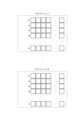
例えば、図7のステップS17において、図9の(1)乃至(3)に示すクラスタが同じグループに属するクラスタと判定されたとする。例えば、図9の(1)に示すクラスタの代表点は、1回目に受信した反射波に基づいてクラスタリングした結果とする。同様に、図9の(2)に示すクラスタの代表点は、2回目に受信した反射波に基づいてクラスタリングした結果とする。また、図9の(3)に示すクラスタの代表点は、3回目に受信した反射波に基づいてクラスタリングした結果とする。For example, suppose that in step S17 of FIG. 7, the clusters shown in (1) to (3) of FIG. 9 are determined to belong to the same group. For example, the representative point of the cluster shown in (1) of FIG. 9 is the result of clustering based on the reflected wave received the first time. Similarly, the representative point of the cluster shown in (2) of FIG. 9 is the result of clustering based on the reflected wave received the second time. Moreover, the representative point of the cluster shown in (3) of FIG. 9 is the result of clustering based on the reflected wave received the third time.
例えば、図8のステップS22における所定の数は、2であるとする。また、図9の(2)に示すクラスタの代表点の近傍には、マルチパスの影響を受けたクラスタの代表点が存在するものとする。この場合、図8のステップS22において、図9の(1)に示すクラスタの代表点の近傍には、クラスタ(2)及び(3)に示すクラスタの代表点が存在し、カウントされるクラスタは2となる。したがって、図9の(1)、(2)、及び(3)のクラスタの代表点は、対象物の検出とし、選抜クラスタとしてよい。一方、図9の(2)に示すマルチパスクラスタの代表点は、(1)に示すクラスタの代表点の近傍範囲内にない。したがって、この場合、対象物として検出しない。このため、物体の検出結果は、(2)のマルチパスクラスタの代表点が除外された、クラスタ(1)、(2)、及び(3)のクラスタの代表点が選抜クラスタの代表点として出力される。一実施形態において、選抜クラスタの代表点の平均値等が、図9の(A)に示すクラスタの代表点として出力されてよい。このように、一実施形態によれば、マルチパスクラスタの代表点は除去される。For example, the predetermined number in step S22 in FIG. 8 is 2. In addition, it is assumed that a representative point of a cluster affected by multipath exists near the representative point of the cluster shown in (2) in FIG. 9. In this case, in step S22 in FIG. 8, the representative points of the clusters shown in clusters (2) and (3) exist near the representative point of the cluster shown in (1) in FIG. 9, and the number of clusters counted is 2. Therefore, the representative points of the clusters shown in (1), (2), and (3) in FIG. 9 may be detected as objects and selected as clusters. On the other hand, the representative point of the multipath cluster shown in (2) in FIG. 9 is not within the vicinity of the representative point of the cluster shown in (1). Therefore, in this case, it is not detected as an object. Therefore, the representative points of the clusters (1), (2), and (3) in the object detection result are output as the representative points of the selected cluster, excluding the representative point of the multipath cluster (2). In one embodiment, the average value of the representative points of the selected cluster, etc. may be output as the representative point of the cluster shown in FIG. 9 (A). Thus, according to one embodiment, representative points of multipath clusters are removed.
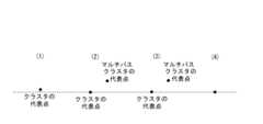
例えば、図8のステップS22における所定の数は、2であるとする。また、図10の(2)及び(3)に示すクラスタの代表点の近傍には、マルチパスの影響を受けたクラスタの代表点(マルチパスクラスタの代表点)が存在するものとする。今回は、図10の(2)のマルチパスクラスタの代表点の近傍範囲内にクラスタ代表点をカウントし、図10の(3)のマルチパスクラスタの代表点は1つしかないので、所定数の2に満たない。したがって、この場合、対象物の検出としない。すなわち、(2)及び(3)のマルチパスクラスタの代表点は除外される。For example, the predetermined number in step S22 in FIG. 8 is assumed to be 2. Also, assume that representative points of clusters affected by multipath (representative points of multipath clusters) exist near the representative points of the clusters shown in (2) and (3) in FIG. 10. In this case, the cluster representative points are counted within the vicinity of the representative point of the multipath cluster in (2) in FIG. 10, and since there is only one representative point of the multipath cluster in (3) in FIG. 10, this does not reach the predetermined number of 2. Therefore, in this case, the target object is not detected. In other words, the representative points of the multipath clusters in (2) and (3) are excluded.
一方、図10の(1)、(2)又は(3)のいずれのクラスタの代表点の近傍範囲内にクラスタの代表点をカウントしても、カウント数は2となる。例えば、図10の(1)に示すクラスタの代表点の近傍範囲内には、(2)及び(3)のクラスタの代表点が存在する。また、図10の(2)に示すクラスタの代表点の近傍範囲内には、(1)及び(3)のクラスタ代表点が存在する。さらに、図10の(3)に示すクラスタの代表点の近傍範囲内には、(2)及び(3)のクラスタ代表点が存在する。したがって、この場合、(1)、(2)、及び(3)のクラスタの代表点は対象物の検出とし、選抜クラスタとしてよい。また、この場合、(2)及び(3)のマルチパスクラスタの代表点は、いずれのクラスタの代表点の近傍範囲内でもないため、対象物の検出とせずに、除去されてよい。このため、物体の検出結果は、選抜クラスタの代表点の平均値等として、図9の(A)に示すクラスタの代表点として出力される。図10に示す破線は、各代表点の相対的な位置関係を示すための概念的な基準線である。On the other hand, even if the representative points of the clusters are counted within the vicinity of the representative points of any of the clusters (1), (2), and (3) in FIG. 10, the count number is 2. For example, within the vicinity of the representative point of the cluster shown in (1) in FIG. 10, the representative points of the clusters (2) and (3) exist. Furthermore, within the vicinity of the representative point of the cluster shown in (2) in FIG. 10, the representative points of the clusters (1) and (3) exist. Furthermore, within the vicinity of the representative point of the cluster shown in (3) in FIG. 10, the representative points of the clusters (2) and (3) exist. Therefore, in this case, the representative points of the clusters (1), (2), and (3) may be regarded as detection of the object and may be regarded as the selected cluster. Furthermore, in this case, the representative points of the multipath clusters (2) and (3) are not within the vicinity of the representative points of any of the clusters, and therefore may be removed without being regarded as detection of the object. Therefore, the object detection result is output as the representative point of the cluster shown in FIG. 9A, as the average value of the representative points of the selected clusters, etc. The dashed lines in Figure 10 are conceptual reference lines that show the relative positional relationships of each representative point.
このように、一実施形態に係る電子機器1によれば、複数回の検出結果に対して信号処理を行うことにより、物体の検出精度を向上することができる。すなわち、一実施形態に係る電子機器1によれば、物体の検出精度を低減し得るクラスタを除去することができる。このように、一実施形態に係る電子機器1によれば、ノイズ点すなわちマルチパスによる影響を除去することができる。In this way, the
図8のステップS22において、所定の数は、適宜設定されるものとして説明した。しかしながら、図8のステップS22における所定の数は、例えば、電子機器1における送信波の送信及び/又は反射波の受信に基づいて設定されてもよい。例えば、図8のステップS22における所定の数は、送信波が送信された回数と同じ数としてもよい。また、例えば、図8のステップS22における所定の数は、反射波が受信された回数と同じ数としてもよい。このように、一実施形態に係る電子機器1において、信号処理部10は、所定のクラスタに基づいて、物体の検出結果を出力してよい。ここで、所定のクラスタとは、物体を複数回検出した結果のそれぞれにクラスタリングを行うことにより得られる複数のクラスタのうち、それぞれの代表点から所定の距離以内に他のクラスタの代表点が、送信波が送信される回数以上存在するクラスタとしてよい。In step S22 of FIG. 8, the predetermined number has been described as being set appropriately. However, the predetermined number in step S22 of FIG. 8 may be set, for example, based on the transmission of the transmission wave and/or the reception of the reflected wave in the
図8及び図9においては、各クラスタの代表点に着目して、選抜クラスタの選定を実行した。しかしながら、各クラスタにおける点群に着目して、選抜クラスタの選定を実行してもよい。In Figures 8 and 9, the selection of the selected clusters is performed by focusing on the representative points of each cluster. However, the selection of the selected clusters may also be performed by focusing on the point clouds in each cluster.
上述した実施形態において、放射パターンを変化させる際、位相制御部24は送信波の位相を制御した(変化させた)。しかしながら、一実施形態に係る電子機器1は、放射パターンを変化させる際、送信波の位相のみならず、当該送信波の振幅を変化させてもよい。In the above-described embodiment, when changing the radiation pattern, the
本開示を諸図面及び実施例に基づき説明してきたが、当業者であれば本開示に基づき種々の変形又は修正を行うことが容易であることに注意されたい。したがって、これらの変形又は修正は本開示の範囲に含まれることに留意されたい。例えば、各機能部に含まれる機能などは論理的に矛盾しないように再配置可能である。複数の機能部等は、1つに組み合わせられたり、分割されたりしてよい。上述した本開示に係る各実施形態は、それぞれ説明した各実施形態に忠実に実施することに限定されるものではなく、適宜、各特徴を組み合わせたり、一部を省略したりして実施され得る。つまり、本開示の内容は、当業者であれば本開示に基づき種々の変形および修正を行うことができる。したがって、これらの変形および修正は本開示の範囲に含まれる。例えば、各実施形態において、各機能部、各手段、各ステップなどは論理的に矛盾しないように他の実施形態に追加し、若しくは、他の実施形態の各機能部、各手段、各ステップなどと置き換えることが可能である。また、各実施形態において、複数の各機能部、各手段、各ステップなどを1つに組み合わせたり、或いは分割したりすることが可能である。また、上述した本開示の各実施形態は、それぞれ説明した各実施形態に忠実に実施することに限定されるものではなく、適宜、各特徴を組み合わせたり、一部を省略したりして実施することもできる。Although the present disclosure has been described based on the drawings and examples, it should be noted that a person skilled in the art can easily make various modifications or corrections based on the present disclosure. Therefore, it should be noted that these modifications or corrections are included in the scope of the present disclosure. For example, the functions included in each functional unit can be rearranged so as not to be logically inconsistent. Multiple functional units, etc. may be combined into one or divided. Each embodiment of the present disclosure described above is not limited to being implemented faithfully to each of the embodiments described above, and can be implemented by combining each feature as appropriate or omitting some of them. In other words, the contents of the present disclosure can be modified and corrected in various ways by a person skilled in the art based on the present disclosure. Therefore, these modifications and corrections are included in the scope of the present disclosure. For example, in each embodiment, each functional unit, each means, each step, etc. can be added to other embodiments so as not to be logically inconsistent, or replaced with each functional unit, each means, each step, etc. of other embodiments. In addition, in each embodiment, multiple functional units, each means, each step, etc. can be combined into one or divided. Furthermore, each of the above-described embodiments of the present disclosure is not limited to being implemented faithfully according to each of the described embodiments, but may be implemented by combining each feature or omitting some features as appropriate.
上述した実施形態は、電子機器1としての実施のみに限定されるものではない。例えば、上述した実施形態は、電子機器1のような機器の制御方法として実施してもよい。さらに、例えば、上述した実施形態は、電子機器1のような機器及び/又は任意のコンピュータが実行するプログラムとして実施してもよい。The above-described embodiment is not limited to implementation only as
また、上述した実施形態に係る電子機器1は、送信アンテナアレイ25及び受信アンテナアレイ31など、いわゆるレーダセンサを構成する部品を含むものとして説明した。しかしながら、一実施形態に係る電子機器は、例えば信号処理部10のような構成として実施してもよい。この場合、信号処理部10は、例えば、送信アンテナアレイ25及び受信アンテナアレイ31などが扱う信号を処理する機能を有するものとして実施してよい。The
1 電子機器
10 信号処理部
11 信号発生処理部
12 受信信号処理部
13 通信インタフェース
21 送信DAC
22 送信回路
23 ミリ波送信回路
24 位相制御部
25 送信アンテナアレイ
31 受信アンテナアレイ
32 ミキサ
33 受信回路
34 受信ADC1
22
Claims (8)
Translated fromJapanese前記送信波が反射された反射波を受信する受信アンテナと、
前記送信波の放射パターンを制御する制御部と、
前記送信波として送信される送信信号及び前記反射波として受信される受信信号に基づいて物体を検出する信号処理部と、
を備える電子機器であって、
前記制御部は、前記送信波が所定の単位で複数回送信される場合に放射パターンを変化させた送信波を少なくとも1回含むように制御し、
前記信号処理部は、前記物体を前記複数回検出した結果のそれぞれにクラスタリングを行うことにより得られる複数のクラスタのうち、それぞれの代表点から所定の距離以内に他のクラスタの代表点が所定の回数以上存在するクラスタに基づいて、前記物体の検出結果を出力し、
前記それぞれの代表点から所定の距離以内に他のクラスタの代表点が所定の回数以上存在するクラスタの代表点の座標の平均値、中央値、最小値、又は最大値のいずれかを、前記物体の検出結果として出力する、電子機器。 A transmitting antenna for transmitting a transmission wave;
a receiving antenna for receiving a reflected wave of the transmission wave;
A control unit that controls a radiation pattern of the transmission wave;
a signal processing unit that detects an object based on a transmission signal transmitted as the transmission wave and a reception signal received as the reflected wave;
An electronic device comprising:
The control unit controls the transmission wave such that, when the transmission wave is transmitted a plurality of times in a predetermined unit, the transmission wave includes at least one transmission wave having a changed radiation pattern;
the signal processing unit outputs a detection result of the object based on a cluster in which a representative point of another cluster exists a predetermined number of times or more within a predetermined distance from a representative point of each cluster among a plurality of clusters obtained by performing clustering on each of the results of detecting the object a plurality of times;
an electronic device that outputs, as a detection result for the object, one of the average, median, minimum, or maximum of the coordinates of the representative point of a cluster where the representative point of another cluster exists within a predetermined distance from the respective representative point a predetermined number of times or more .
前記送信波が反射された反射波を受信アンテナによって受信するステップと、
前記送信波の放射パターンを制御するステップと、
前記送信波として送信される送信信号及び前記反射波として受信される受信信号に基づいて物体を検出するステップと、
前記送信波が所定の単位で複数回送信される場合に放射パターンを変化させた送信波を少なくとも1回含むように制御するステップと、
前記物体を前記複数回検出した結果のそれぞれにクラスタリングを行うことにより得られる複数のクラスタのうち、それぞれの代表点から所定の距離以内に他のクラスタの代表点が所定の回数以上存在するクラスタに基づいて、前記物体の検出結果を出力するステップと、
前記それぞれの代表点から所定の距離以内に他のクラスタの代表点が所定の回数以上存在するクラスタの代表点の座標の平均値、中央値、最小値、又は最大値のいずれかを、前記物体の検出結果として出力するステップと、
を含む、電子機器の制御方法。 transmitting a transmission wave by a transmitting antenna;
receiving a reflected wave of the transmission wave by a receiving antenna;
controlling a radiation pattern of the transmission wave;
detecting an object based on a transmission signal transmitted as the transmission wave and a reception signal received as the reflected wave;
a step of controlling the transmission wave such that, when the transmission wave is transmitted a plurality of times in a predetermined unit, at least one transmission wave having a changed radiation pattern is included;
a step of outputting a detection result of the object based on a plurality of clusters obtained by performing clustering on each of the results of detecting the object a plurality of times, the clusters each having a representative point of another cluster present within a predetermined distance a predetermined number of times;
outputting, as a detection result of the object, any one of an average value, a median value, a minimum value, or a maximum value of coordinates of representative points of clusters in which representative points of other clusters exist within a predetermined distance from each of the representative points a predetermined number of times or more;
A method for controlling an electronic device, comprising:
送信アンテナによって送信波を送信するステップと、
前記送信波が反射された反射波を受信アンテナによって受信するステップと、
前記送信波の放射パターンを制御するステップと、
前記送信波として送信される送信信号及び前記反射波として受信される受信信号に基づいて物体を検出するステップと、
前記送信波が所定の単位で複数回送信される場合に放射パターンを変化させた送信波を少なくとも1回含むように制御するステップと、
前記物体を前記複数回検出した結果のそれぞれにクラスタリングを行うことにより得られる複数のクラスタのうち、それぞれの代表点から所定の距離以内に他のクラスタの代表点が所定の回数以上存在するクラスタに基づいて、前記物体の検出結果を出力するステップと、
前記それぞれの代表点から所定の距離以内に他のクラスタの代表点が所定の回数以上存在するクラスタの代表点の座標の平均値、中央値、最小値、又は最大値のいずれかを、前記物体の検出結果として出力するステップと、
を実行させる、プログラム。 For electronic devices,
transmitting a transmission wave by a transmitting antenna;
receiving a reflected wave of the transmission wave by a receiving antenna;
controlling a radiation pattern of the transmission wave;
detecting an object based on a transmission signal transmitted as the transmission wave and a reception signal received as the reflected wave;
a step of controlling the transmission wave such that, when the transmission wave is transmitted a plurality of times in a predetermined unit, at least one transmission wave having a changed radiation pattern is included;
a step of outputting a detection result of the object based on a plurality of clusters obtained by performing clustering on each of the results of detecting the object a plurality of times, the clusters each having a representative point of another cluster present within a predetermined distance a predetermined number of times;
outputting, as a detection result of the object, any one of an average value, a median value, a minimum value, or a maximum value of coordinates of representative points of clusters in which representative points of other clusters exist within a predetermined distance from each of the representative points a predetermined number of times or more;
A program to execute.
Priority Applications (5)
| Application Number | Priority Date | Filing Date | Title |
|---|---|---|---|
| JP2021140484AJP7560419B2 (en) | 2021-08-30 | 2021-08-30 | Electronic device, electronic device control method, and program |
| US18/684,423US20250216531A1 (en) | 2021-08-30 | 2022-08-09 | Electronic device, method for controlling electronic device, and program |
| EP22864204.7AEP4397997A1 (en) | 2021-08-30 | 2022-08-09 | Electronic device, electronic device control method, and program |
| CN202280058368.6ACN117881981A (en) | 2021-08-30 | 2022-08-09 | Electronic device, method for controlling electronic device, and program |
| PCT/JP2022/030483WO2023032619A1 (en) | 2021-08-30 | 2022-08-09 | Electronic device, electronic device control method, and program |
Applications Claiming Priority (1)
| Application Number | Priority Date | Filing Date | Title |
|---|---|---|---|
| JP2021140484AJP7560419B2 (en) | 2021-08-30 | 2021-08-30 | Electronic device, electronic device control method, and program |
Publications (2)
| Publication Number | Publication Date |
|---|---|
| JP2023034316A JP2023034316A (en) | 2023-03-13 |
| JP7560419B2true JP7560419B2 (en) | 2024-10-02 |
Family
ID=85412249
Family Applications (1)
| Application Number | Title | Priority Date | Filing Date |
|---|---|---|---|
| JP2021140484AActiveJP7560419B2 (en) | 2021-08-30 | 2021-08-30 | Electronic device, electronic device control method, and program |
Country Status (5)
| Country | Link |
|---|---|
| US (1) | US20250216531A1 (en) |
| EP (1) | EP4397997A1 (en) |
| JP (1) | JP7560419B2 (en) |
| CN (1) | CN117881981A (en) |
| WO (1) | WO2023032619A1 (en) |
Citations (4)
| Publication number | Priority date | Publication date | Assignee | Title |
|---|---|---|---|---|
| US20050285773A1 (en) | 2002-06-06 | 2005-12-29 | Roadeye Flr General Partnership | Forward-looking radar system |
| JP2008026239A (en) | 2006-07-24 | 2008-02-07 | Murata Mfg Co Ltd | Radar |
| JP2019144094A (en) | 2018-02-20 | 2019-08-29 | 株式会社デンソーテン | Radar device and method for processing signal |
| JP2021012140A (en) | 2019-07-08 | 2021-02-04 | Jrcモビリティ株式会社 | Radar system |
Family Cites Families (1)
| Publication number | Priority date | Publication date | Assignee | Title |
|---|---|---|---|---|
| CN112394334B (en) | 2019-08-16 | 2024-05-28 | 富士通株式会社 | Clustering device and method for radar reflection points and electronic equipment |
- 2021
- 2021-08-30JPJP2021140484Apatent/JP7560419B2/enactiveActive
- 2022
- 2022-08-09WOPCT/JP2022/030483patent/WO2023032619A1/ennot_activeCeased
- 2022-08-09USUS18/684,423patent/US20250216531A1/enactivePending
- 2022-08-09CNCN202280058368.6Apatent/CN117881981A/enactivePending
- 2022-08-09EPEP22864204.7Apatent/EP4397997A1/enactivePending
Patent Citations (4)
| Publication number | Priority date | Publication date | Assignee | Title |
|---|---|---|---|---|
| US20050285773A1 (en) | 2002-06-06 | 2005-12-29 | Roadeye Flr General Partnership | Forward-looking radar system |
| JP2008026239A (en) | 2006-07-24 | 2008-02-07 | Murata Mfg Co Ltd | Radar |
| JP2019144094A (en) | 2018-02-20 | 2019-08-29 | 株式会社デンソーテン | Radar device and method for processing signal |
| JP2021012140A (en) | 2019-07-08 | 2021-02-04 | Jrcモビリティ株式会社 | Radar system |
Also Published As
| Publication number | Publication date |
|---|---|
| JP2023034316A (en) | 2023-03-13 |
| WO2023032619A1 (en) | 2023-03-09 |
| EP4397997A1 (en) | 2024-07-10 |
| US20250216531A1 (en) | 2025-07-03 |
| CN117881981A (en) | 2024-04-12 |
Similar Documents
| Publication | Publication Date | Title |
|---|---|---|
| WO2021019934A1 (en) | Electronic device, electronic device control method, and program | |
| JP7572920B2 (en) | Electronic device, electronic device control method, and program | |
| JP7113878B2 (en) | ELECTRONIC DEVICE, ELECTRONIC DEVICE CONTROL METHOD, AND PROGRAM | |
| JP7518849B2 (en) | Electronic device, electronic device control method, and program | |
| JP7163342B2 (en) | ELECTRONIC DEVICE, ELECTRONIC DEVICE CONTROL METHOD, AND PROGRAM | |
| JP7560419B2 (en) | Electronic device, electronic device control method, and program | |
| JP7646501B2 (en) | Electronic device, electronic device control method, and program | |
| JP7525453B2 (en) | Electronic device, electronic device control method, and program | |
| JP7646500B2 (en) | Electronic device, electronic device control method, and program | |
| JP7550751B2 (en) | Electronic device, electronic device control method, and program | |
| JP7223197B2 (en) | ELECTRONIC DEVICE, ELECTRONIC DEVICE CONTROL METHOD, AND PROGRAM | |
| JP7636160B2 (en) | Electronic device, electronic device control method, and program | |
| JP7466023B2 (en) | Electronic device, electronic device control method, and program | |
| US20230400553A1 (en) | Electronic device, method for controlling electronic device, and program | |
| WO2023002871A1 (en) | Electronic device, method for controlling electronic device, and program | |
| JP2022186843A (en) | ELECTRONIC DEVICE, ELECTRONIC DEVICE CONTROL METHOD, AND PROGRAM |
Legal Events
| Date | Code | Title | Description |
|---|---|---|---|
| A621 | Written request for application examination | Free format text:JAPANESE INTERMEDIATE CODE: A621 Effective date:20231117 | |
| A131 | Notification of reasons for refusal | Free format text:JAPANESE INTERMEDIATE CODE: A131 Effective date:20240618 | |
| A521 | Request for written amendment filed | Free format text:JAPANESE INTERMEDIATE CODE: A523 Effective date:20240808 | |
| TRDD | Decision of grant or rejection written | ||
| A01 | Written decision to grant a patent or to grant a registration (utility model) | Free format text:JAPANESE INTERMEDIATE CODE: A01 Effective date:20240827 | |
| A61 | First payment of annual fees (during grant procedure) | Free format text:JAPANESE INTERMEDIATE CODE: A61 Effective date:20240919 | |
| R150 | Certificate of patent or registration of utility model | Ref document number:7560419 Country of ref document:JP Free format text:JAPANESE INTERMEDIATE CODE: R150 |