JP7560412B2 - Agricultural support system, and device and method for creating a call route for agricultural machinery - Google Patents
Agricultural support system, and device and method for creating a call route for agricultural machineryDownload PDFInfo
- Publication number
- JP7560412B2 JP7560412B2JP2021107442AJP2021107442AJP7560412B2JP 7560412 B2JP7560412 B2JP 7560412B2JP 2021107442 AJP2021107442 AJP 2021107442AJP 2021107442 AJP2021107442 AJP 2021107442AJP 7560412 B2JP7560412 B2JP 7560412B2
- Authority
- JP
- Japan
- Prior art keywords
- call
- agricultural machine
- route
- agricultural
- point
- Prior art date
- Legal status (The legal status is an assumption and is not a legal conclusion. Google has not performed a legal analysis and makes no representation as to the accuracy of the status listed.)
- Active
Links
Images


Landscapes
- Guiding Agricultural Machines (AREA)
Description
Translated fromJapanese本開示は、農業支援システム、農業機械の呼び出し経路を作成する装置および方法に関する。The present disclosure relates to an agricultural support system, and an apparatus and method for creating call routes for agricultural machinery.
圃場で使用される農業機械の自動化に向けた研究開発が進められている。例えば、GNSS(Global Navigation Satellite System)などの測位システムを利用して圃場内を自動で走行するトラクタ、コンバイン、および田植機などの作業車両が実用化されている。Research and development is underway to automate agricultural machinery used in fields. For example, work vehicles such as tractors, combine harvesters, and rice transplanters that can navigate autonomously within fields using positioning systems such as the Global Navigation Satellite System (GNSS) have been put to practical use.
特許文献1は、圃場内を自動で走行しながら作物を収穫し、収穫された収穫物を貯留部に貯留する収穫機のための自動走行制御システムを開示している。この自動走行制御システムでは、収穫機が、予め設定された走行経路に沿って自動で走行しながら圃場の作物を収穫する。収穫機は、貯留部に貯留された収穫物の貯留量を測定し、貯留量が一定量以上になると、収穫作業を中断し、収穫物の排出のための動作を行う。収穫物の排出を行うとき、収穫機は、走行経路から離脱して、排出作業が行われる排出位置に到達するための排出経路を算出し、排出経路に沿って自動走行する。排出経路は、予め設定された排出位置と、収穫物の排出のために自動走行が中断されたときの機体の位置と、圃場の収穫状況とに基づいて生成される。具体的には、収穫作業がまだ終了していない未作業地を通過せずに排出位置に到達する経路が、排出経路として生成される。特許文献1には、収穫物の排出だけでなく、燃料の補給のために同様の技術を用いることができることも記載されている。
特許文献2は、走行予定ルートに含まれる旋回ルート上に設定された補給位置で、肥料、農薬、苗、種等の資材の補給を行う農業機械を開示している。この農業機械では、自動走行中に運転者がスイッチを操作することで、走行予定ルート内のある旋回ルート上の位置から他の旋回ルート上の位置に補給位置を変更することができる。Patent Document 2 discloses an agricultural machine that supplies fertilizer, pesticides, seedlings, seeds, and other materials at supply positions set on a turning route included in the planned driving route. With this agricultural machine, the driver can operate a switch while the machine is driving automatically to change the supply position from a position on one turning route within the planned driving route to a position on another turning route.
本開示は、農業機械を適切な経路で所望の地点に呼び出すことを可能にするための新規な技術を提供する。The present disclosure provides a novel technology that enables agricultural machinery to be summoned to a desired location via an appropriate route.
本開示の一態様による農業支援システムは、自動運転を行う農業機械を呼び出し地点に呼び出す端末装置と、前記呼び出し地点に向かうために前記農業機械が移動する呼び出し経路を、前記農業機械の作業済み領域を除く領域に作成する処理装置とを備える。An agricultural support system according to one aspect of the present disclosure includes a terminal device that calls an autonomously operating agricultural machine to a call point, and a processing device that creates a call route along which the agricultural machine travels to reach the call point, in an area excluding the area where the agricultural machine has already completed work.
本開示の他の態様による処理装置は、1つ以上のプロセッサと、コンピュータプログラムを格納したメモリと、を備える。前記コンピュータプログラムは、前記1つ以上のプロセッサに、自動運転を行う農業機械を呼び出し地点に呼び出す端末装置から、前記呼び出し地点の位置情報を含む呼び出し信号を受信すること、または、前記農業機械を呼び出し地点に呼び出す操作をユーザから受け付けることと、前記呼び出し信号、または前記ユーザによる前記操作に基づいて、前記呼び出し地点に向かうために前記農業機械が移動する呼び出し経路を、前記農業機械の作業済み領域を除く領域に作成することと、を実行させる。A processing device according to another aspect of the present disclosure includes one or more processors and a memory storing a computer program. The computer program causes the one or more processors to execute the following: receive a call signal including location information of a call point from a terminal device that calls an autonomously-operated agricultural machine to the call point, or accept an operation from a user to call the agricultural machine to the call point; and create a call route along which the agricultural machine moves to head to the call point, in an area excluding an area where the agricultural machine has already been worked on, based on the call signal or the operation by the user.
本開示の包括的または具体的な態様は、装置、システム、方法、集積回路、コンピュータプログラム、もしくはコンピュータが読み取り可能な非一時的記憶媒体、またはこれらの任意の組み合わせによって実現され得る。コンピュータが読み取り可能な記憶媒体は、揮発性の記憶媒体を含んでいてもよいし、不揮発性の記憶媒体を含んでいてもよい。装置は、複数の装置で構成されていてもよい。装置が2つ以上の装置で構成される場合、当該2つ以上の装置は、1つの機器内に配置されてもよいし、分離した2つ以上の機器内に分かれて配置されていてもよい。The general or specific aspects of the present disclosure may be realized by an apparatus, a system, a method, an integrated circuit, a computer program, or a computer-readable non-transitory storage medium, or any combination thereof. The computer-readable storage medium may include a volatile storage medium or a non-volatile storage medium. The apparatus may be composed of multiple devices. When the apparatus is composed of two or more devices, the two or more devices may be arranged in one device or may be arranged separately in two or more separate devices.
本開示の実施形態によれば、農業機械を適切な経路で所望の地点に呼び出すことが可能になる。According to an embodiment of the present disclosure, it becomes possible to call agricultural machinery to a desired location via an appropriate route.
以下、本開示の実施形態を説明する。ただし、必要以上に詳細な説明は省略することがある。例えば、既によく知られた事項の詳細な説明および実質的に同一の構成に関する重複する説明を省略することがある。これは、以下の説明が不必要に冗長になることを避け、当業者の理解を容易にするためである。なお、発明者は、当業者が本開示を十分に理解するために添付図面および以下の説明を提供するのであって、これらによって特許請求の範囲に記載の主題を限定することを意図するものではない。以下の説明において、同一または類似の機能を有する構成要素については、同一の参照符号を付している。Below, an embodiment of the present disclosure will be described. However, more detailed explanation than necessary may be omitted. For example, detailed explanation of already well-known matters and duplicate explanation of substantially the same configuration may be omitted. This is to avoid the following explanation becoming unnecessarily redundant and to facilitate understanding by those skilled in the art. Note that the inventor provides the attached drawings and the following explanation so that those skilled in the art can fully understand the present disclosure, and does not intend for them to limit the subject matter described in the claims. In the following explanation, components having the same or similar functions are given the same reference symbols.
以下の実施形態は例示であり、本開示の技術は以下の実施形態に限定されない。例えば、以下の実施形態で示される数値、形状、材料、ステップ、ステップの順序、表示画面のレイアウトなどは、あくまでも一例であり、技術的に矛盾が生じない限りにおいて種々の改変が可能である。また、技術的に矛盾が生じない限りにおいて、一の態様と他の態様とを組み合わせることが可能である。The following embodiments are illustrative, and the technology of the present disclosure is not limited to the following embodiments. For example, the numerical values, shapes, materials, steps, order of steps, layout of the display screen, and the like shown in the following embodiments are merely examples, and various modifications are possible as long as no technical contradictions arise. In addition, one aspect can be combined with another aspect as long as no technical contradictions arise.
(実施形態の概要)
まず、本開示の実施形態の概要を説明する。 (Overview of the embodiment)
First, an overview of the embodiment of the present disclosure will be described.
本開示の一実施形態による農業支援システムは、自動運転を行う農業機械を呼び出し地点に呼び出す端末装置と、呼び出し地点に向かうために農業機械が移動する呼び出し経路を、農業機械の作業済み領域を除く領域に作成する処理装置とを備える。An agricultural support system according to one embodiment of the present disclosure includes a terminal device that calls an autonomously operating agricultural machine to a call point, and a processing device that creates a call route along which the agricultural machine travels to reach the call point, in an area excluding the area where the agricultural machine has already completed work.
本開示において「農業機械」は、農業用途で使用される機械を意味する。農業機械の例は、トラクタ、収穫機、田植機、乗用管理機、野菜移植機、草刈機、播種機、施肥機、および農業用移動ロボットを含む。トラクタのような作業車両が単独で「農業機械」として機能する場合だけでなく、作業車両に装着され、または牽引される作業機(インプルメント)と作業車両の全体が一つの「農業機械」として機能する場合がある。農業機械は、圃場内の地面に対して、耕耘、播種、防除、施肥、作物の植え付け、または収穫などの農作業を行う。これらの農作業を「対地作業」または単に「作業」と称することがある。車両型の農業機械が農作業を行いながら走行することを「作業走行」と称することがある。In this disclosure, "agricultural machinery" refers to machinery used for agricultural purposes. Examples of agricultural machinery include tractors, harvesters, rice transplanters, riding cultivators, vegetable transplanters, mowers, sowing machines, fertilizer applicators, and agricultural mobile robots. Not only can a work vehicle such as a tractor function as an "agricultural machine" by itself, but also a work vehicle and an implement attached to or towed by the work vehicle can function as a single "agricultural machine." Agricultural machinery performs agricultural work such as plowing, sowing, pest control, fertilizing, planting crops, or harvesting on the ground in a field. These agricultural works are sometimes referred to as "ground work" or simply "work." Vehicle-type agricultural machinery traveling while performing agricultural work is sometimes referred to as "work travel."
「自動運転」は、運転者による手動操作によらず、制御装置の働きによって農業機械の移動を制御することを意味する。自動運転を行う農業機械は「自動運転農機」または「ロボット農機」と呼ばれることがある。自動運転中、農業機械の移動だけでなく、農作業の動作も自動で制御されてもよい。農業機械が車両型の機械である場合、自動運転によって農業機械が走行することを「自動走行」と称する。制御装置は、農業機械の移動に必要な操舵、移動速度の調整、移動の開始および停止の少なくとも1つを制御し得る。作業機が装着された作業車両を制御する場合、制御装置は、作業機の昇降、作業機の動作の開始および停止などの動作を制御してもよい。自動運転による移動には、農業機械が所定の経路に沿って目的地に向かう移動のみならず、追尾目標に追従する移動も含まれ得る。自動運転を行う農業機械は、部分的にユーザの指示に基づいて移動する機能を備えていてもよい。また、自動運転を行う農業機械は、自動運転モードに加えて、運転者の手動操作によって移動する手動運転モードで動作してもよい。手動によらず、制御装置の働きによって農業機械の操舵を行うことを「自動操舵」と称する。制御装置の一部または全部が農業機械の外部にあってもよい。農業機械の外部にある制御装置と農業機械との間では、制御信号、コマンド、またはデータなどの通信が行われ得る。自動運転を行う農業機械は、人がその農業機械の移動の制御に関与することなく、周囲の環境をセンシングしながら自律的に移動してもよい。自律的な移動が可能な農業機械は、無人で圃場内または圃場外(例えば道路)を走行することができる。自律移動中に、障害物の検出および障害物の回避動作を行ってもよい。"Autonomous driving" means that the movement of the agricultural machine is controlled by the action of a control device, not by manual operation by the driver. An agricultural machine that performs automatic driving is sometimes called an "automatic driving agricultural machine" or a "robot agricultural machine". During automatic driving, not only the movement of the agricultural machine but also the operation of agricultural work may be automatically controlled. When the agricultural machine is a vehicle-type machine, the traveling of the agricultural machine by automatic driving is called "automatic driving". The control device may control at least one of steering, adjustment of the moving speed, and starting and stopping of the movement required for the movement of the agricultural machine. When controlling a work vehicle equipped with a working machine, the control device may control operations such as raising and lowering the working machine, starting and stopping the operation of the working machine. The movement by automatic driving may include not only the movement of the agricultural machine toward the destination along a predetermined route, but also the movement of the agricultural machine following a tracking target. An agricultural machine that performs automatic driving may have a function of moving partially based on the instruction of a user. In addition, an agricultural machine that performs automatic driving may operate in a manual driving mode in which the agricultural machine moves by manual operation of the driver in addition to the automatic driving mode. Steering an agricultural machine by the action of a control device, rather than manually, is called "automatic steering." A part or all of the control device may be external to the agricultural machine. Control signals, commands, data, and the like may be communicated between the agricultural machine and a control device external to the agricultural machine. An agricultural machine that performs automatic driving may move autonomously while sensing the surrounding environment, without a human being being involved in controlling the movement of the agricultural machine. An agricultural machine capable of autonomous movement can travel unmanned in a field or outside the field (e.g., on a road). During autonomous movement, the machine may detect obstacles and perform obstacle avoidance operations.
「端末装置」は、農業機械を所望の位置に呼び出すための装置であり、「呼び出し装置」または「呼び出し端末」と称することもある。端末装置は、例えばスマートフォン、タブレットコンピュータ、ラップトップコンピュータ、リモートコントローラ(リモコン)などの携帯型の装置であってもよいし、デスクトップ型のパーソナルコンピュータ(PC)などの据え置き型の装置であってもよい。端末装置は、農業機械が農作業を行う圃場内で使用されてもよいし、農業機械が農作業を行う圃場から離れた場所で使用されてもよい。A "terminal device" is a device for calling an agricultural machine to a desired location, and may also be called a "calling device" or a "calling terminal." A terminal device may be a portable device such as a smartphone, tablet computer, laptop computer, or remote controller, or a stationary device such as a desktop personal computer (PC). A terminal device may be used in a field where the agricultural machine performs farm work, or may be used at a location away from the field where the agricultural machine performs farm work.
農業機械が農作業を行う圃場内で端末装置が使用される場合、端末装置は、例えば農業機械が農作業を行っている最中に、端末装置の位置またはその付近に農業機械を呼び出すために使用され得る。この場合、端末装置は、GNSS受信機などの測位装置を備え得る。端末装置は、ユーザが端末装置における特定のボタンを押すなどの操作に応答して、端末装置の位置情報を含む呼び出し信号を農業機械に送信するように構成され得る。ユーザは、端末装置を操作することにより、農業機械を「呼び出し地点」に呼び出することができる。呼び出し地点は、例えば、ユーザが端末装置を操作した位置(「操作位置」と呼ぶ。)を中心とする半径数メートルの範囲内の地点に設定され得る。例えば、操作位置と同じ位置、または、操作位置から数メートル離れた位置が呼び出し地点として設定され得る。端末装置は、操作位置と一致する地点を呼び出し地点として入力したり、操作位置から数メートル離れた所定の位置を呼び出し地点として入力したりすることができる。これにより、端末装置の位置またはその付近に呼び出し地点を設定することができる。When the terminal device is used in a field where an agricultural machine performs farm work, the terminal device can be used to call the agricultural machine to the position of the terminal device or in its vicinity, for example, while the agricultural machine is performing farm work. In this case, the terminal device can be equipped with a positioning device such as a GNSS receiver. The terminal device can be configured to transmit a call signal including the position information of the terminal device to the agricultural machine in response to an operation such as a user pressing a specific button on the terminal device. The user can call the agricultural machine to a "call point" by operating the terminal device. The call point can be set, for example, to a point within a radius of several meters centered on the position where the user operated the terminal device (referred to as the "operation position"). For example, the same position as the operation position or a position several meters away from the operation position can be set as the call point. The terminal device can input a point that matches the operation position as the call point, or input a predetermined position several meters away from the operation position as the call point. This makes it possible to set the call point to the position of the terminal device or in its vicinity.
端末装置は、自身の位置情報の代わりに、ユーザが指定した位置の情報を含む呼び出し信号を農業機械に送信するように構成されていてもよい。例えば、ユーザは、端末装置にインストールされたアプリケーションソフトウェアを起動して、圃場の地図を端末装置のディスプレイに表示させ、地図上で所望の地点を指定して農業機械をその地点に呼び出す操作を行うことができる。この操作に応答して、端末装置は、ユーザによって指定された地点を呼び出し地点として、その位置情報を含む呼び出し信号を農業機械に送信することができる。農業機械は、その呼び出し信号に応答して、位置情報が示す呼び出し地点に向かって移動する。この場合、端末装置およびユーザは、必ずしも農業機械から離れた位置にいる必要はない。農業機械に搭乗したユーザが端末装置を操作して所望の地点を指定し、農業機械をその地点に移動させてもよい。端末装置は、農業機械に搭載されていてもよい。The terminal device may be configured to transmit to the agricultural machine a call signal including information on a location designated by the user instead of its own location information. For example, the user can start application software installed on the terminal device, display a map of the farm field on the display of the terminal device, and specify a desired point on the map to call the agricultural machine to that point. In response to this operation, the terminal device can transmit to the agricultural machine a call signal including the location information of the point designated by the user as the call point. In response to the call signal, the agricultural machine moves toward the call point indicated by the location information. In this case, the terminal device and the user do not necessarily need to be located far from the agricultural machine. A user on board the agricultural machine may operate the terminal device to specify a desired point and move the agricultural machine to that point. The terminal device may be mounted on the agricultural machine.
農業機械が農作業を行う圃場から離れた場所で端末装置が使用される場合、端末装置は、例えば農業機械を監視するユーザの自宅または事業所にある監視用コンピュータであってもよい。監視用コンピュータは、据え置き型のコンピュータでもよいし、スマートフォン、タブレットコンピュータ、またはラップトップコンピュータなどの携帯型のコンピュータでもよい。この場合も、ユーザは、端末装置にインストールされたアプリケーションソフトウェアを起動して、圃場の地図をディスプレイに表示させ、地図上で所望の地点を指定して農業機械をその地点に呼び出す操作を行うことができる。これにより、端末装置を用いた遠隔操作によって農業機械を所望の地点に呼び出すことができる。When the terminal device is used in a location away from the field where the agricultural machinery performs agricultural work, the terminal device may be, for example, a monitoring computer at the user's home or place of business that monitors the agricultural machinery. The monitoring computer may be a stationary computer or a portable computer such as a smartphone, tablet computer, or laptop computer. In this case, too, the user can start up application software installed on the terminal device, display a map of the field on the display, specify a desired location on the map, and call the agricultural machinery to that location. This allows the agricultural machinery to be called to a desired location by remote control using the terminal device.
「処理装置」は、農業機械が移動する経路を作成する装置である。以下の説明において、処理装置を「経路作成装置」と称することがある。処理装置は、例えば1つ以上のプロセッサと、1つ以上のメモリとを備えるコンピュータであり得る。その場合、プロセッサは、メモリに格納されたコンピュータプログラムを実行することによって経路を作成することができる。処理装置は、農業機械に搭載されていてもよいし、農業機械とは離れた場所に設置されていてもよい。農業機械に搭載された電子制御ユニット(ECU)の1つが処理装置としての機能を備えていてもよい。あるいは、農業機械とネットワークを介して通信を行うサーバなどの外部のコンピュータが処理装置として機能してもよい。さらには、端末装置が処理装置の機能を有していてもよい。すなわち、端末装置のプロセッサが、呼び出し地点への呼び出し経路を作成し、その呼び出し経路の情報を含む呼び出し信号を農業機械に送信してもよい。その場合、端末装置が上記の処理装置を内蔵していることになる。このように、端末装置と処理装置とが独立した別個の装置である必要はなく、1つの装置が端末装置および処理装置の両方の機能を備えていてもよい。The "processing device" is a device that creates a route along which the agricultural machine moves. In the following description, the processing device may be referred to as a "route creation device." The processing device may be, for example, a computer equipped with one or more processors and one or more memories. In this case, the processor can create a route by executing a computer program stored in the memory. The processing device may be mounted on the agricultural machine, or may be installed at a location remote from the agricultural machine. One of the electronic control units (ECUs) mounted on the agricultural machine may have the function of the processing device. Alternatively, an external computer such as a server that communicates with the agricultural machine via a network may function as the processing device. Furthermore, the terminal device may have the function of the processing device. In other words, the processor of the terminal device may create a call route to a call point and transmit a call signal including information on the call route to the agricultural machine. In that case, the terminal device will have the above-mentioned processing device built in. In this way, the terminal device and the processing device do not need to be independent and separate devices, and one device may have the functions of both the terminal device and the processing device.
「作業済み領域」は、圃場において農業機械による農作業が行われた領域を意味する。例えば農業機械が、トラクタと、トラクタに連結されたインプルメントとの集合体である場合、インプルメントによって農作業が行われた領域が作業済み領域に該当する。作業済み領域は、農業機械が農作業を行いながら移動している間、記憶装置に継続的に記録され得る。作業済み領域を記憶する記憶装置は、農業機械に設けられていてもよいし、農業機械にネットワークを介して接続されたオンラインストレージなどの装置であってもよい。圃場内で、複数の農業機械が農作業を行う場合、いずれかの農業機械によって当該農作業が行われた領域が作業済み領域として記録され得る。作業済み領域は、例えば、農業機械の位置情報と、予め設定された農業機械の作業幅とに基づいて決定され得る。農業機械の位置情報は、例えば農業機械が備えるGNSS受信機などを含む測位装置によって生成され得る。農業機械の位置情報は、農業機械と通信を行うサーバなどの外部のコンピュータによって生成されてもよい。その場合、外部のコンピュータは、農業機械に設けられたGNSS受信機および慣性計測装置(IMU)などの装置からの出力データを逐次受信し、それらのデータに基づいて農業機械の位置を計算し、その位置情報を農業機械に送信する。作業済み領域を決定して記憶装置に記憶させる動作は、上記の処理装置(すなわち経路作成装置)によって行われてもよいし、他の装置によって行われてもよい。例えば、農業機械に搭載されたECU、または農業機械と通信するサーバなどのコンピュータが作業済み領域を記録してもよい。The "worked area" refers to an area in a field where agricultural work has been performed by an agricultural machine. For example, if the agricultural machine is an assembly of a tractor and an implement connected to the tractor, the area where agricultural work has been performed by the implement corresponds to the worked area. The worked area may be continuously recorded in a storage device while the agricultural machine is moving while performing agricultural work. The storage device that stores the worked area may be provided in the agricultural machine, or may be a device such as an online storage connected to the agricultural machine via a network. When multiple agricultural machines perform agricultural work in a field, the area where the agricultural work has been performed by any of the agricultural machines may be recorded as the worked area. The worked area may be determined, for example, based on the position information of the agricultural machine and the working width of the agricultural machine that is set in advance. The position information of the agricultural machine may be generated by a positioning device including, for example, a GNSS receiver equipped in the agricultural machine. The position information of the agricultural machine may be generated by an external computer such as a server that communicates with the agricultural machine. In this case, the external computer sequentially receives output data from devices such as a GNSS receiver and an inertial measurement unit (IMU) provided on the agricultural machine, calculates the position of the agricultural machine based on that data, and transmits the position information to the agricultural machine. The operation of determining the worked area and storing it in the storage device may be performed by the above-mentioned processing device (i.e., the route creation device) or by another device. For example, the worked area may be recorded by an ECU mounted on the agricultural machine, or a computer such as a server that communicates with the agricultural machine.
上記の実施形態によれば、農業機械の監視者などのユーザが、端末装置を操作して農業機械を呼び出し地点に呼び出すことができる。ユーザは、例えば農業機械が圃場内で農作業を行うために必要な農業資材(例えば、種、農薬、肥料、苗など)を補給したり、農業機械に搭乗したり、農業機械の状態を確認したりするために、農業機械を所望の地点に呼び出すことができる。このため、ユーザが農業機械の位置まで移動することなく、補給などの作業を行うことができる。また、ユーザが移動したり、端末装置を操作したりすることにより、呼び出し地点を変更することができる。このため、特許文献1のように農業機械の移動先の位置(排出位置または補給位置)が固定されているシステムや、特許文献2のように農業機械の経路を作成した時点で資材の補給位置が決定されるシステムと比較して、利便性を大きく向上させることができる。According to the above embodiment, a user such as an agricultural machine monitor can operate a terminal device to call the agricultural machine to a call point. The user can call the agricultural machine to a desired point, for example, to supply agricultural materials (e.g., seeds, pesticides, fertilizer, seedlings, etc.) necessary for the agricultural machine to perform farm work in a field, to board the agricultural machine, or to check the status of the agricultural machine. This allows the user to perform work such as supplying without moving to the location of the agricultural machine. In addition, the user can change the call point by moving or operating the terminal device. This greatly improves convenience compared to a system in which the destination position of the agricultural machine (discharge position or supply position) is fixed as in
さらに、上記の実施形態によれば、呼び出し地点に向かうために農業機械が移動する経路である呼び出し経路が、農業機械の作業済み領域を除く領域に作成される。これにより、例えば耕耘、播種、または植え付けなどの農作業が行われた作業済み領域における地面を農業機械が踏み荒らすことなく、農業機械を所望の呼び出し地点に呼び出すことができる。したがって、作業の効果が損なわれたり、作物に損傷を与えたりする可能性を低減することができる。Furthermore, according to the above embodiment, a call route, which is the route along which the agricultural machine travels to reach the call point, is created in an area excluding the area in which the agricultural machine has already been worked on. This allows the agricultural machine to be called to the desired call point without the agricultural machine trampling the ground in the area in which work has already been done, such as plowing, sowing, or planting. This reduces the possibility of the effectiveness of the work being compromised or the crops being damaged.
農業支援システムは、農業機械が呼び出し経路に沿って移動するように農業機械の動作を制御する制御装置をさらに備えていてもよい。制御装置は、農業機械が備える駆動装置(例えば、原動機、変速装置、操舵装置など)に制御信号を送信することにより、農業機械を呼び出し経路に沿って移動させる。制御装置は、農業機械が備えるECUなどの装置であってもよいし、農業機械と通信を行うサーバなどの外部のコンピュータであってもよい。制御装置が、前述の処理装置の機能、すなわち呼び出し経路を作成する機能を兼ねていてもよい。The agricultural support system may further include a control device that controls the operation of the agricultural machine so that the agricultural machine moves along the call path. The control device moves the agricultural machine along the call path by sending a control signal to a drive device (e.g., a prime mover, a transmission, a steering device, etc.) equipped in the agricultural machine. The control device may be a device such as an ECU equipped in the agricultural machine, or an external computer such as a server that communicates with the agricultural machine. The control device may also have the function of the above-mentioned processing device, i.e., the function of creating a call path.
農業機械が呼び出しを受けたとき、制御装置は、農業機械に農作業を少なくとも部分的に停止させた状態で、呼び出し経路に沿って農業機械を移動させてもよい。例えば、制御装置は、農業機械に農作業を完全に停止させた状態で、呼び出し経路に沿って農業機械を移動させてもよい。あるいは、制御装置は、農業機械が移動する一部の区間において、農作業を実行させながら呼び出し経路に沿って農業機械を移動させてもよい。When the agricultural machine receives a call, the control device may move the agricultural machine along the call path with the agricultural machine at least partially ceasing agricultural work. For example, the control device may move the agricultural machine along the call path with the agricultural machine completely ceasing agricultural work. Alternatively, the control device may move the agricultural machine along the call path while performing agricultural work in a portion of the section along which the agricultural machine moves.
農業支援システムは、農業機械によって農作業が行われた領域を作業済み領域として記憶する記憶装置をさらに備えていてもよい。端末装置は、呼び出し地点の位置情報を含む呼び出し信号を処理装置に送信するように構成され得る。処理装置は、当該位置情報、および記憶装置に記憶された作業済み領域に基づいて、呼び出し経路を作成することができる。The agricultural support system may further include a storage device that stores an area where agricultural work has been performed by the agricultural machine as a worked area. The terminal device may be configured to transmit a call signal including location information of the call point to the processing device. The processing device can create a call route based on the location information and the worked area stored in the storage device.
処理装置は、農業機械が予め設定された目標経路に沿って移動している間、測位装置によって特定された農業機械の位置と、農業機械の作業幅とに基づき、作業済み領域を決定し、作業済み領域を記憶装置に記憶させてもよい。作業済み領域を記憶装置に記憶させる処理は、処理装置に限らず、他の装置が行ってもよい。While the agricultural machine is moving along a preset target route, the processing device may determine the worked area based on the position of the agricultural machine identified by the positioning device and the working width of the agricultural machine, and store the worked area in the storage device. The process of storing the worked area in the storage device may be performed by another device, not limited to the processing device.
処理装置は、農業機械が予め設定された目標経路に沿って移動しているときに端末装置から呼び出しを受けた場合、目標経路のうち、農業機械の進行方向側に位置する部分を含む経路を呼び出し経路として決定してもよい。目標経路のうち、農業機械の進行方向側に位置する部分は、まだ作業が行われていないため、農業機械によって地面が踏まれても問題が生じないからである。When the processing device receives a call from the terminal device while the agricultural machine is moving along a preset target route, the processing device may determine, as the call route, a route that includes a portion of the target route that is located in the direction of travel of the agricultural machine. This is because no work has been performed on the portion of the target route that is located in the direction of travel of the agricultural machine, and therefore no problems will arise even if the agricultural machine steps on the ground.
処理装置は、例えば以下の(1)および(2)の観点から呼び出し経路を作成することができる。
(1)端末装置から呼び出しを受けたときの農業機械の位置と呼び出し地点との間に作業済み領域がない場合、呼び出し地点に向かう直線状の経路を呼び出し経路として決定する。
(2)農業機械の位置と呼び出し地点との間に作業済み領域がある場合、作業済み領域の外周に沿って呼び出し地点に向かう経路を呼び出し経路として決定する。
ここで、農業機械の位置と呼び出し地点との間に作業済み領域があるか否かは、農業機械の位置と呼び出し地点とを結ぶ直線が作業済み領域と重なるか否かによって判断され得る。「農業機械の位置」とは、農業機械に設定された基準位置を意味する。例えば、農業機械がGNSS受信機を備えており、GNSS受信機の位置(すなわち取付位置)が基準位置として定められている場合、GNSS受信機の取付位置が当該農業機械の位置に該当する。或いは、農業機械において、GNSS受信機の取付位置から数メートル(m)程度離れた位置が基準位置として定められている場合、取付位置から数メートル程度離れた位置が農業機械の位置に該当する。「直線状の経路」とは、大半が直線状である経路を意味し、一部に曲線状または折れ線状の部分が含まれていてもよい。例えば、呼び出しを受けたときの位置から微小距離(例えば1m)だけ前進し、方向転換して呼び出し地点に向かって直線的に進むような経路も「直線状の経路」に該当する。 The processing device can create a call path from the viewpoints of (1) and (2) below, for example.
(1) If there is no completed work area between the position of the agricultural machine when a call is received from the terminal device and the call point, a straight line route toward the call point is determined as the call route.
(2) If there is a worked area between the position of the agricultural machine and the call point, a route along the periphery of the worked area toward the call point is determined as the call route.
Here, whether or not there is a work-completed area between the position of the agricultural machine and the call point can be determined by whether or not a straight line connecting the position of the agricultural machine and the call point overlaps with the work-completed area. "Position of the agricultural machine" means a reference position set on the agricultural machine. For example, if the agricultural machine is equipped with a GNSS receiver and the position of the GNSS receiver (i.e., the mounting position) is set as the reference position, the mounting position of the GNSS receiver corresponds to the position of the agricultural machine. Alternatively, if a position several meters (m) away from the mounting position of the GNSS receiver is set as the reference position on the agricultural machine, a position several meters away from the mounting position corresponds to the position of the agricultural machine. "Straight path" means a path that is mostly straight, and may include a curved or broken line part. For example, a path that moves forward a small distance (e.g., 1 m) from the position when the call is received, changes direction, and moves straight toward the call point also corresponds to a "straight path".
農業機械は、例えば、並列する複数の主経路と、複数の主経路を接続する1つ以上の旋回経路とを含む目標経路に沿って走行するように制御され得る。その場合、処理装置は、農業機械が複数の主経路の1つに沿って移動しているときに端末装置から呼び出しを受け、かつ、呼び出しを受けたときの農業機械の位置と呼び出し地点との間に作業済み領域がある場合、農業機械の位置から当該主経路に沿って直進した後、作業済み領域の外周に沿って呼び出し地点に向かう経路、および、農業機械の位置から作業済み領域の反対側に旋回して逆方向に直進した後、作業済み領域の外周に沿って前記呼び出し地点に向かう経路のうち、短い経路を呼び出し経路として決定してもよい。このような動作により、農業機械、呼び出し地点、および作業済み領域の位置関係に応じて、短時間で呼び出し地点に到達する呼び出し経路を決定することができる。The agricultural machine may be controlled to travel along a target route including, for example, multiple parallel main routes and one or more turning routes connecting the multiple main routes. In this case, when the processing device receives a call from the terminal device while the agricultural machine is moving along one of the multiple main routes and there is a worked area between the position of the agricultural machine at the time of receiving the call and the call point, the processing device may determine as the call route the shorter of a route that travels straight from the position of the agricultural machine along the main route and then along the periphery of the worked area toward the call point, and a route that travels straight from the position of the agricultural machine to the opposite side of the worked area, travels in the opposite direction, and then along the periphery of the worked area toward the call point. Through such an operation, a call route that reaches the call point in a short time can be determined according to the relative positions of the agricultural machine, the call point, and the worked area.
このように、処理装置は、呼び出しを受けたとき、作業済み領域を経由せずに呼び出し地点に向かう2つ以上の経路を作成し、それらの経路の中から最短の経路を呼び出し経路として決定してもよい。In this way, when a call is received, the processing device may create two or more routes to the call point without passing through the worked area, and determine the shortest route from among those routes as the call route.
前述のように、端末装置は、GNSS受信機を備える携帯端末であってもよい。その場合、携帯端末は、GNSS受信機から出力された信号に基づいて生成された携帯端末の位置情報を含む呼び出し信号を処理装置に送信してもよい。当該位置情報が示す地点(すなわち、携帯端末が操作されたときの位置情報が示す地点)、または、当該位置情報が示す地点から数メートル離れた地点が呼び出し地点として決定され得る。As mentioned above, the terminal device may be a mobile terminal equipped with a GNSS receiver. In this case, the mobile terminal may transmit to the processing device a call signal including position information of the mobile terminal generated based on a signal output from the GNSS receiver. The location indicated by the position information (i.e., the location indicated by the position information when the mobile terminal is operated) or a location several meters away from the location indicated by the position information may be determined as the call location.
端末装置は、農業機械を遠隔監視するための監視コンピュータであってもよい。監視コンピュータは、ユーザの操作に応答して、呼び出し地点の位置情報を含む呼び出し信号を処理装置に送信してもよい。The terminal device may be a monitoring computer for remotely monitoring the agricultural machine. The monitoring computer may transmit a call signal including location information of the call point to the processing device in response to a user operation.
本開示の他の実施形態による処理装置は、1つ以上のプロセッサと、コンピュータプログラムを格納したメモリとを備える。前記コンピュータプログラムは、前記1つ以上のプロセッサに、自動運転を行う農業機械を呼び出し地点に呼び出す端末装置から、前記呼び出し地点の位置情報を含む呼び出し信号を受信すること、または、前記農業機械を呼び出し地点に呼び出す操作をユーザから受け付けることと、前記呼び出し信号、または前記ユーザによる前記操作に基づいて、前記呼び出し地点に向かうために前記農業機械が移動する呼び出し経路を、前記農業機械の作業済み領域を除く領域に作成することとを実行させる。A processing device according to another embodiment of the present disclosure includes one or more processors and a memory storing a computer program. The computer program causes the one or more processors to receive a call signal including location information of a call point from a terminal device that calls an autonomously operating agricultural machine to the call point, or to accept an operation from a user to call the agricultural machine to the call point, and to create a call route along which the agricultural machine moves to head to the call point, in an area excluding an area where the agricultural machine has already been worked on, based on the call signal or the operation by the user.
本開示のさらに他の実施形態によるコンピュータによって実行される方法は、(a)自動運転を行う農業機械を呼び出し地点に呼び出す端末装置から、前記呼び出し地点の位置情報を含む呼び出し信号を受信すること、または、前記農業機械を呼び出し地点に呼び出す操作をユーザから受け付けることと、(b)前記呼び出し信号、または前記ユーザによる前記操作に基づいて、前記呼び出し地点に向かうために前記農業機械が移動する呼び出し経路を、前記農業機械の作業済み領域を除く領域に作成することと、を含む。A method executed by a computer according to yet another embodiment of the present disclosure includes: (a) receiving a call signal including location information of a call location from a terminal device that calls an autonomously-operated agricultural machine to the call location, or receiving an operation from a user to call the agricultural machine to the call location; and (b) creating a call route along which the agricultural machine moves to travel to the call location, in an area excluding an area where the agricultural machine has already been worked on, based on the call signal or the operation by the user.
本開示のさらに他の実施形態によるコンピュータプログラムは、(a)コンピュータに、自動運転を行う農業機械を呼び出し地点に呼び出す端末装置から、前記呼び出し地点の位置情報を含む呼び出し信号を受信すること、または、前記農業機械を呼び出し地点に呼び出す操作をユーザから受け付けることと、(b)前記呼び出し信号、または前記ユーザによる前記操作に基づいて、前記呼び出し地点に向かうために前記農業機械が移動する呼び出し経路を、前記農業機械の作業済み領域を除く領域に作成することと、を含む。A computer program according to yet another embodiment of the present disclosure includes: (a) receiving, from a terminal device that calls an autonomously-operated agricultural machine to a call location, a call signal including location information of the call location, or receiving an operation from a user to call the agricultural machine to the call location; and (b) creating, based on the call signal or the operation by the user, a call route along which the agricultural machine moves to travel to the call location, in an area excluding an area where the agricultural machine has already completed work.
以下、農業機械の一例であるトラクタなどの作業車両に本開示の技術を適用した実施形態を説明する。本開示の技術は、トラクタなどの作業車両に限らず、自動運転を行う任意の農業機械に適用することができる。農業機械は、例えば、収穫機、田植機、乗用管理機、野菜移植機、草刈機、播種機、施肥機などのトラクタ以外の作業車両、または農業用移動ロボットであってもよい。Below, an embodiment in which the technology of the present disclosure is applied to a work vehicle such as a tractor, which is an example of agricultural machinery, is described. The technology of the present disclosure is not limited to work vehicles such as tractors, but can be applied to any agricultural machinery that performs autonomous driving. The agricultural machinery may be, for example, a work vehicle other than a tractor, such as a harvester, rice transplanter, riding management machine, vegetable transplanter, grass cutter, seeding machine, or fertilizer applicator, or an agricultural mobile robot.
(実施形態1)
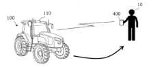
図1は、本開示の例示的な実施形態による農業支援システムの概要を説明するための図である。図1には、作業車両100と、作業車両100を呼び出し地点に呼び出す呼び出し端末400とが例示されている。作業車両100は前述の農業機械の一例であり、呼び出し端末400は前述の端末装置の一例である。本実施形態における作業車両100はトラクタである。トラクタは、後部および前部の一方または両方に作業機(インプルメント)を装着することができる。トラクタは、インプルメントの種類に応じた農作業を行いながら圃場内を自動で走行することができる。本実施形態において行われる農作業は、例えば耕耘、播種、作物の植え付けなど、作業後の地面を作業車両100が踏んでしまうと作業の効果が損なわれ得る任意の作業であり得る。以下の説明において、作業車両100がインプルメントを制御して作業を実行させることを「作業車両100が作業を行う」と表現することがある。なお、本実施形態および後述する他の実施形態における技術は、トラクタ以外の農業機械にも同様に適用することができる。 (Embodiment 1)
FIG. 1 is a diagram for explaining an overview of an agricultural support system according to an exemplary embodiment of the present disclosure. FIG. 1 illustrates a
作業車両100は、自動運転機能を備える。すなわち、作業車両100は、手動によらず、制御装置の働きによって走行する。本実施形態における制御装置は、作業車両100の内部に設けられ、作業車両100の速度および操舵の両方を制御することができる。The
作業車両100は、GNSS受信機を含む測位装置110を備える。制御装置は、測位装置110によって特定された作業車両100の位置と、予め記憶装置に記憶された目標経路とに基づいて、作業車両100を自動で走行させる。制御装置は、作業車両100の走行制御に加えて、インプルメントの動作の制御も行う。これにより、作業車両100は、自動で走行しながらインプルメントを用いて作業を実行することができる。The
呼び出し端末400は、例えばスマートフォン、タブレットコンピュータ、またはリモコンなどの携帯機器であり得る。呼び出し端末400は、圃場において作業車両100から離れた位置にいるユーザ10によって使用され得る。ユーザ10は、例えば作業車両100の監視者、または農業資材(例えば、肥料、農薬、苗など)の補給もしくは燃料の補給などの作業を行う作業者であり得る。呼び出し端末400は、GNSS受信機を備える。呼び出し端末400は、ユーザ10の操作に応じて、呼び出し端末400の位置情報を含む呼び出し信号を作業車両100に送信する。作業車両100は、呼び出し信号を受信すると、呼び出し端末400の位置情報が示す呼び出し地点まで自動で移動する。The
本実施形態における作業車両100は、作業車両100が移動する経路を作成する処理装置(「経路作成装置」とも称する。)を備える。経路作成装置は、作業車両100が圃場内で作業を実行するときに走行する経路(以下、「目標経路」と称する。)を作成する。さらに、経路作成装置は、呼び出し端末400によって呼び出されたときに作業車両100が呼び出し地点に向かうための呼び出し経路も作成する。経路作成装置は、呼び出し経路を、作業車両100の作業済み領域を除く領域に作成する。作業済み領域は、作業車両100によって農作業が行われた領域である。作業済み領域は、作業車両100が作業走行を行っている間、経路作成装置または他の処理装置によって継続的に記憶装置に記録される。作業済み領域は、例えば、測位装置110によって特定された作業車両100の位置と、予め設定された作業車両100の作業幅とに基づいて決定され得る。作業幅は、作業車両100に連結されたインプルメントによって作業が行われる領域の幅である。経路作成装置は、呼び出し端末400から送信された呼び出し信号に含まれる位置情報と、記憶装置に格納された作業済み領域とに基づいて、呼び出し経路を作成する。制御装置は、作成された呼び出し経路に沿って作業車両100の駆動装置(例えば、操舵装置、変速装置、動力装置など)を制御する。これにより、作業車両100は、作業済み領域を経由することなく、呼び出し地点まで移動することができる。The
このように、本実施形態における作業車両100は、呼び出し端末400から呼び出しを受けると、呼び出し端末400の呼び出し地点まで自動で移動する。このとき、作業車両100は、作業済み領域を経由しない呼び出し経路に沿って呼び出し地点に向かう。これにより、作業済み領域を作業車両100が踏むことによって作業の効果が損なわれることを回避することができる。In this way, when the
以下、本実施形態におけるシステムの構成および動作のより具体的な例を説明する。Below, we will explain a more specific example of the system configuration and operation in this embodiment.
[1.構成]
図2は、作業車両100、および作業車両100に連結された作業機(インプルメント)300の例を模式的に示す側面図である。本実施形態における作業車両100は、手動運転モードと自動運転モードの両方の機能を備える。自動運転モードにおいて、作業車両100は無人で走行することができる。 [1. Configuration]
2 is a side view showing a schematic example of the
図2に示すように、作業車両100は、車両本体101と、原動機(エンジン)102と、変速装置(トランスミッション)103とを備える。車両本体101には、タイヤ104(車輪)と、キャビン105とが設けられている。タイヤ104は、一対の前輪104Fと一対の後輪104Rとを含む。キャビン105の内部に運転席107、操舵装置106、操作端末200、および操作のためのスイッチ群が設けられている。前輪104Fおよび後輪104Rの一方または両方は、タイヤではなくクローラであってもよい。As shown in FIG. 2, the
図2に示す作業車両100は、複数のカメラ120をさらに備える。カメラ120は、例えば作業車両100の前後左右に設けられ得る。カメラ120は、作業車両100の周囲の環境を撮影し、画像データを生成する。カメラ120が取得した画像は、例えば遠隔監視を行うための監視用コンピュータ(「監視端末」とも称する。)に送信され得る。当該画像は、例えば無人運転時に作業車両100を監視するために用いられ得る。カメラ120は必要に応じて設けられ、不要であれば省略することも可能である。The
作業車両100は、測位装置110をさらに備える。測位装置110は、GNSS受信機を含む。GNSS受信機は、GNSS衛星からの信号を受信するアンテナと、アンテナが受信した信号に基づいて作業車両100の位置を決定する処理回路とを備える。測位装置110は、GNSS衛星から送信されるGNSS信号を受信し、GNSS信号に基づいて測位を行う。GNSSは、GPS(Global Positioning System)、QZSS(Quasi-Zenith Satellite System、例えばみちびき)、GLONASS、Galileo、およびBeiDouなどの衛星測位システムの総称である。本実施形態における測位装置110は、キャビン105の上部に設けられているが、他の位置に設けられていてもよい。The
測位装置110は、GNSS受信機に代えて、あるいは加えて、LiDARセンサなどの他の種類のデバイスを含んでいてもよい。測位装置110は、カメラ120が取得したデータを測位に利用してもよい。作業車両100が走行する環境内に特徴点として機能する地物が存在する場合、LiDARセンサまたはカメラ120によって取得されたデータと、予め記憶装置に記録された環境地図とに基づいて、作業車両100の位置を高い精度で推定することができる。LiDARセンサまたはカメラ120をGNSS受信機と併用してもよい。LiDARセンサまたはカメラ120が取得したデータを用いて、GNSS信号に基づく位置データを補正または補完することで、より高い精度で作業車両100の位置を特定できる。測位装置110は、さらに、慣性計測装置(IMU)からの信号を利用して位置データを補完することができる。IMUは、作業車両100の傾きおよび微小な動きを計測することができる。IMUによって取得されたデータを用いて、GNSS信号に基づく位置データを補完することにより、測位の性能を向上させることができる。The
作業車両100は、複数の障害物センサ130をさらに備える。図2に示す例では、キャビン105の前方および後方に障害物センサ130が設けられている。障害物センサ130は、他の部位にも配置され得る。例えば、車両本体101の側部、前部、および後部の任意の位置に、1つまたは複数の障害物センサ130が設けられ得る。障害物センサ130は、自動走行時に周囲の障害物を検出して停止したり迂回したりするために用いられる。The
原動機102は、例えばディーゼルエンジンであり得る。ディーゼルエンジンに代えて電動モータが使用されてもよい。変速装置103は、変速によって作業車両100の推進力および移動速度を変化させることができる。変速装置103は、作業車両100の前進と後進とを切り換えることもできる。The
操舵装置106は、ステアリングホイールと、ステアリングホイールに接続されたステアリングシャフトと、ステアリングホイールによる操舵を補助するパワーステアリング装置とを含む。前輪104Fは操舵輪であり、その切れ角(「操舵角」とも称する。)を変化させることにより、作業車両100の走行方向を変化させることができる。前輪104Fの操舵角は、ステアリングホイールを操作することによって変化させることができる。パワーステアリング装置は、前輪104Fの操舵角を変化させるための補助力を供給する油圧装置または電動モータを含む。自動操舵が行われるときには、作業車両100内に配置された制御装置からの制御により、油圧装置または電動モータの力によって操舵角が自動で調整される。The
車両本体101の後部には、連結装置108が設けられている。連結装置108は、例えば3点支持装置(「3点リンク」または「3点ヒッチ」とも称する。)、PTO(Power Take Off)軸、ユニバーサルジョイント、および通信ケーブルを含む。連結装置108によって作業機300を作業車両100に着脱することができる。連結装置108は、例えば油圧装置によって3点リンクを昇降させ、作業機300の位置または姿勢を変化させることができる。また、ユニバーサルジョイントを介して作業車両100から作業機300に動力を送ることができる。作業車両100は、作業機300を引きながら、作業機300に所定の作業を実行させることができる。連結装置は、車両本体101の前方に設けられていてもよい。その場合、作業車両100の前方に作業機を接続することができる。A
図2に示す作業機300は、ロータリ耕耘機であるが、作業機300はロータリ耕耘機に限定されない。例えば、シーダ(播種機)、スプレッダ(施肥機)、移植機、モーア(草刈機)、レーキ作業機、ベーラ(集草機)、ハーベスタ(収穫機)、スプレイヤ、またはハローなどの、任意の作業機を作業車両100に接続して使用することができる。The working
図2に示す作業車両100は、有人運転が可能であるが、無人運転のみに対応していてもよい。その場合には、キャビン105、操舵装置106、および運転席107などの、有人運転にのみ必要な構成要素は、作業車両100に設けられていなくてもよい。無人の作業車両100は、自律走行、またはユーザによる遠隔操作によって走行することができる。The
図3は、作業車両100、作業機300、および呼び出し端末400の構成例を示すブロック図である。作業車両100と作業機300は、連結装置108に含まれる通信ケーブルを介して互いに通信することができる。作業車両100と呼び出し端末400は、無線通信によって互いに通信することができる。Figure 3 is a block diagram showing an example configuration of the
図3の例における作業車両100は、測位装置110、カメラ120、障害物センサ130、操作端末200に加え、駆動装置140、作業車両100の動作状態を検出するセンサ群150、制御システム160、通信装置190、および操作スイッチ群210を備える。測位装置110は、GNSS受信機111と、RTK受信機112と、慣性計測装置(IMU)115とを備える。センサ群150は、ステアリングホイールセンサ152と、切れ角センサ154、車軸センサ156とを含む。制御システム160は、記憶装置170と、制御装置180とを備える。制御装置180は、複数の電子制御ユニット(ECU)181から185を備える。作業機300は、駆動装置340と、制御装置380と、通信装置390とを備える。呼び出し端末400は、GNSS受信機410と、入力装置420と、表示装置430と、記憶装置450と、プロセッサ460と、通信装置490とを備える。なお、図3には、作業車両100による自動運転の動作との関連性が相対的に高い構成要素が示されており、それ以外の構成要素の図示は省略されている。In the example of FIG. 3, the
図3に示す測位装置110は、RTK(Real Time Kinematic)-GNSSを利用して作業車両100の測位を行う。図4は、RTK-GNSSによる測位を行う作業車両100の例を示す概念図である。RTK-GNSSによる測位では、複数のGNSS衛星50から送信されるGNSS信号に加えて、基準局60から送信される補正信号が利用される。基準局60は、作業車両100が走行する圃場の付近(例えば、作業車両100から1km以内の位置)に設置され得る。基準局60は、複数のGNSS衛星50から受信したGNSS信号に基づいて、例えばRTCMフォーマットの補正信号を生成し、測位装置110に送信する。測位装置110におけるGNSS受信機111は、複数のGNSS衛星50から送信されるGNSS信号を受信する。RTK受信機112は、アンテナおよびモデムを含み、基準局60から送信される補正信号を受信する。測位装置110は、GNSS信号および補正信号に基づき、作業車両100の位置を計算することによって測位を行うプロセッサを備え得る。RTK-GNSSを用いることにより、例えば誤差数cmの精度で測位を行うことが可能である。緯度、経度および高度の情報を含む位置情報が、RTK-GNSSによる高精度の測位によって取得される。測位装置110は、例えば1秒間に1回から10回程度の頻度で、作業車両100の位置を計算する。The
なお、測位方法はRTK-GNSSに限らず、必要な精度の位置情報が得られる任意の測位方法(干渉測位法または相対測位法など)を用いることができる。例えば、VRS(Virtual Reference Station)またはDGPS(Differential Global Positioning System)を利用した測位を行ってもよい。基準局60から送信される補正信号を用いなくても必要な精度の位置情報が得られる場合は、補正信号を用いずに位置情報を生成してもよい。その場合、測位装置110は、RTK受信機112を備えていなくてもよい。The positioning method is not limited to RTK-GNSS, and any positioning method (such as interferometric positioning or relative positioning) that can obtain position information with the required accuracy can be used. For example, positioning may be performed using a Virtual Reference Station (VRS) or a Differential Global Positioning System (DGPS). If position information with the required accuracy can be obtained without using a correction signal transmitted from the
本実施形態における測位装置110は、さらにIMU115を備える。IMU115は、3軸加速度センサおよび3軸ジャイロスコープを備える。IMU115は、3軸地磁気センサなどの方位センサを備えていてもよい。IMU115は、モーションセンサとして機能し、作業車両100の加速度、速度、変位、および姿勢などの諸量を示す信号を出力することができる。測位装置110は、GNSS信号および補正信号に加えて、IMU115から出力された信号に基づいて、作業車両100の位置および向きをより高い精度で推定することができる。IMU115から出力された信号は、GNSS信号および補正信号に基づいて計算される位置の補正または補完に用いられ得る。IMU115は、GNSS信号よりも高い頻度で信号を出力する。その高頻度の信号を利用して、作業車両100の位置および向きをより高い頻度(例えば、10Hz以上)で計測することができる。IMU115に代えて、3軸加速度センサおよび3軸ジャイロスコープを別々に設けてもよい。IMU115は、測位装置110とは別の装置として設けられていてもよい。The
測位装置110は、GNSS受信機111、RTK受信機112、およびIMU115に加えて、またはこれらに代えて、LiDARセンサなどの他の種類のセンサを備えていてもよい。作業車両100が走行する環境によっては、これらのセンサからのデータに基づいて作業車両100の位置および向きを高い精度で推定することができる。The
図3の例では、測位装置110のプロセッサがGNSS受信機111、RTK受信機112、およびIMU115から出力された信号に基づいて作業車両100の位置を計算する。位置の計算は、測位装置110に限らず、他の装置によって実行されてもよい。例えば、制御装置180または外部のコンピュータが、測位に必要な各受信機および各センサの出力データを取得し、それらのデータに基づいて作業車両100の位置を計算してもよい。In the example of FIG. 3, the processor of the
カメラ120は、作業車両100の周囲の環境を撮影する撮像装置であり、イメージセンサ、1つ以上のレンズなどの光学系、および信号処理回路を備える。カメラ120は、作業車両100の走行中、作業車両100の周囲の環境を撮影し、画像(例えば動画像)のデータを生成する。カメラ120によって生成された画像は、例えば遠隔の監視者が監視端末を用いて作業車両100の周囲の環境を確認するときに利用され得る。カメラ120によって生成された画像は、測位または障害物の検出に利用されてもよい。図2に示すように、複数のカメラ120が作業車両100の異なる位置に設けられていてもよいし、単数のカメラが設けられていてもよい。The
障害物センサ130は、作業車両100の周囲に存在する物体を検出する。障害物センサ130は、例えばレーザスキャナまたは超音波ソナーを備え得る。障害物センサ130は、障害物センサ130から所定の距離よりも近くに物体が存在する場合に、障害物が存在することを示す信号を出力する。複数の障害物センサ130が作業車両100の異なる位置に設けられていてもよい。例えば、複数のレーザスキャナと、複数の超音波ソナーとが、作業車両100の異なる位置に配置されていてもよい。そのような多くの障害物センサ130を備えることにより、作業車両100の周囲の障害物の監視における死角を減らすことができる。The
駆動装置140は、前述の原動機102、変速装置103、操舵装置106、および連結装置108などの、作業車両100の走行および作業機300の駆動に必要な各種の装置を含む。原動機102は、例えばディーゼル機関などの内燃機関を備え得る。駆動装置140は、内燃機関に代えて、あるいは内燃機関とともに、トラクション用の電動モータを備えていてもよい。The
ステアリングホイールセンサ152は、作業車両100のステアリングホイールの回転角を計測する。切れ角センサ154は、操舵輪である前輪104Fの切れ角を計測する。ステアリングホイールセンサ152および切れ角センサ154による計測値は、制御装置180による操舵制御に利用される。The
車軸センサ156は、タイヤ104に接続された車軸の回転速度、すなわち単位時間あたりの回転数を計測する。車軸センサ156は、例えば磁気抵抗素子(MR)、ホール素子、または電磁ピックアップを利用したセンサであり得る。車軸センサ156は、例えば、車軸の1分あたりの回転数(単位:rpm)を示す数値を出力する。車軸センサ156は、作業車両100の速度を計測するために使用される。The
記憶装置170は、フラッシュメモリまたは磁気ディスクなどの1つ以上の記憶媒体を含む。記憶装置170は、測位装置110、カメラ120、障害物センサ130、センサ群150、および制御装置180が生成する各種のデータを記憶する。記憶装置170が記憶するデータには、作業車両100が走行する環境内の地図データ、および自動運転における目標経路のデータ、および作業済み領域を示すデータが含まれ得る。記憶装置170は、制御装置180における各ECUに、後述する各種の動作を実行させるコンピュータプログラムも記憶する。そのようなコンピュータプログラムは、記憶媒体(例えば半導体メモリまたは光ディスク等)または電気通信回線(例えばインターネット)を介して作業車両100に提供され得る。そのようなコンピュータプログラムが、商用ソフトウェアとして販売されてもよい。The
制御装置180は、複数のECUを含む。複数のECUは、例えば、速度制御用のECU181、ステアリング制御用のECU182、作業機制御用のECU183、自動運転制御用のECU184、および経路作成用のECU185を含む。ECU181は、駆動装置140に含まれる原動機102、変速装置103、およびブレーキを制御することによって作業車両100の速度を制御する。ECU182は、ステアリングホイールセンサ152の計測値に基づいて、操舵装置106に含まれる油圧装置または電動モータを制御することによって作業車両100のステアリングを制御する。ECU183は、作業機300に所望の動作を実行させるために、連結装置108に含まれる3点リンクおよびPTO軸などの動作を制御する。ECU183はまた、作業機300の動作を制御する信号を生成し、その信号を通信装置190から作業機300に送信する。ECU184は、測位装置110、ステアリングホイールセンサ152、切れ角センサ154、および車軸センサ156から出力される信号に基づいて、自動運転を実現するための演算および制御を行う。自動運転中、ECU184は、ECU181に速度変更の指令を送り、ECU182に操舵角変更の指令を送る。ECU181は、速度変更の指令に応答して原動機102、変速装置103、またはブレーキを制御することによって作業車両100の速度を変化させる。ECU182は、操舵角変更の指令に応答して操舵装置106を制御することによって操舵角を変化させる。ECU185は、前述の処理装置(すなわち経路作成装置)として機能し、作業車両100の目標経路を作成して記憶装置170に記録する。ECU185は、さらに、呼び出し端末400から呼び出されたときに、呼び出し地点に向かう呼び出し経路を作成する。ECU184は、ECU185が作成した経路に沿って作業車両100が移動するように、ECU181、182に必要な指令を送る。The
これらのECUの働きにより、制御装置180は、自動運転を実現する。自動運転時において、制御装置180は、測位装置110によって計測または推定された作業車両100の位置と、記憶装置170に記憶された目標経路または呼び出し経路とに基づいて、駆動装置140を制御する。これにより、制御装置180は、作業車両100を目標経路または呼び出し経路に沿って走行させることができる。These ECUs allow the
制御装置180に含まれる複数のECUは、例えばCAN(Controller Area Network)などのビークルバス規格に従って、相互に通信することができる。CANに代えて、車載イーサネット(登録商標)などの、より高速の通信方式が用いられてもよい。図3において、ECU181から185のそれぞれは、個別のブロックとして示されているが、これらのそれぞれの機能が、複数のECUによって実現されていてもよい。ECU181から185の少なくとも一部の機能を統合した車載コンピュータが設けられていてもよい。制御装置180は、ECU181から185以外のECUを備えていてもよく、機能に応じて任意の個数のECUが設けられ得る。各ECUは、1つ以上のプロセッサを含む処理回路を備える。The multiple ECUs included in the
通信装置190は、作業機300の通信装置390と通信を行う。通信装置190は、例えばISOBUS-TIM等のISOBUS規格に準拠した信号の送受信を、作業機300の通信装置390との間で実行する回路を含む。これにより、作業機300に所望の動作を実行させたり、作業機300から情報を取得したりすることができる。通信装置190は、さらに、Wi-Fi(登録商標)、3G、4Gもしくは5Gなどのセルラー移動体通信、またはBluetooth(登録商標)などの、任意の無線通信規格に準拠した信号の送受信を、呼び出し端末400の通信装置490との間で実行する通信回路およびアンテナを含み得る。通信装置190は、有線または無線のネットワークを介して外部のコンピュータと通信してもよい。外部のコンピュータは、例えば、圃場に関する情報をクラウド上で一元管理し、クラウド上のデータを活用して農業を支援するサーバコンピュータであってもよい。そのような外部のコンピュータが、作業車両100の機能の一部を実行するように構成されていてもよい。例えば、ECU185による経路作成機能を外部のコンピュータが実行してもよい。その場合、外部のコンピュータが前述の「処理装置」としての機能を果たす。The
操作端末200は、作業車両100の走行および作業機300の動作に関する操作をユーザが実行するための端末であり、バーチャルターミナル(VT)とも称される。操作端末200は、タッチスクリーンなどの表示装置、および/または1つ以上のボタンを備え得る。表示装置は、例えば液晶または有機発光ダイオード(OLED)などのディスプレイであり得る。ユーザは、操作端末200を操作することにより、例えば自動運転モードのオン/オフの切り替え、目標経路の設定、地図の記録または編集、および作業機300のオン/オフの切り替えなどの種々の操作を実行することができる。これらの操作の少なくとも一部は、操作スイッチ群210を操作することによっても実現され得る。操作端末200は、作業車両100から取り外せるように構成されていてもよい。作業車両100から離れた場所にいるユーザが、取り外された操作端末200を操作して作業車両100の動作を制御してもよい。ユーザは、操作端末200の代わりに、必要なアプリケーションソフトウェアがインストールされたスマートフォン、タブレットコンピュータ、またはパーソナルコンピュータ(PC)などの機器を操作して作業車両100の動作を制御してもよい。呼び出し端末400が操作端末200の機能を兼ねていてもよい。The
作業機300における駆動装置340は、作業機300が所定の作業を実行するために必要な動作を行う。駆動装置340は、例えば油圧装置、電気モータ、またはポンプなどの、作業機300の用途に応じた装置を含む。制御装置380は、駆動装置340の動作を制御する。制御装置380は、通信装置390を介して作業車両100から送信された信号に応答して、駆動装置340に各種の動作を実行させる。また、作業機300の状態に応じた信号を通信装置390から作業車両100に送信することもできる。The
呼び出し端末400は、例えばスマートフォン、タブレットコンピュータ、またはリモコンなどの携帯機器であり得る。呼び出し端末400におけるGNSS受信機410は、複数のGNSS衛星から送信される信号に基づいて呼び出し端末400の位置の情報を含むデータを出力する。GNSS受信機410は、例えばNMEAフォーマットのデータを出力する。入力装置420は、ユーザからの入力操作を受け付ける装置であり、1つ以上のボタンまたはスイッチを含み得る。表示装置430は、例えば液晶またはOLEDなどのディスプレイであり得る。入力装置420および表示装置430は、タッチスクリーンによって実現されていてもよい。記憶装置450は、例えばフラッシュメモリなどの半導体記憶媒体を含み得る。記憶装置450は、プロセッサ460によって実行されるコンピュータプログラム、およびプロセッサ460によって生成された各種のデータを記憶する。プロセッサ460は、記憶装置450に格納されたコンピュータプログラムを実行することにより、以下の動作を実行する。プロセッサ460は、ユーザが入力装置420を用いた呼び出しの操作に応答して、呼び出し端末400の位置情報を含む呼び出し信号を、通信装置490から作業車両100の通信装置190に送信する。呼び出し端末400の位置情報は、GNSS受信機410から出力された信号に基づいて生成される。The calling
図5は、キャビン105の内部に設けられる操作端末200および操作スイッチ群210の例を示す模式図である。キャビン105の内部には、ユーザが操作可能な複数のスイッチを含むスイッチ群210が配置されている。操作スイッチ群210は、例えば、主変速または副変速の変速段を選択するためのスイッチ、自動運転モードと手動運転モードとを切り替えるためのスイッチ、前進と後進とを切り替えるためのスイッチ、および作業機300を昇降するためのスイッチ等を含み得る。なお、作業車両100が無人運転のみを行い、有人運転の機能を備えていない場合、作業車両100が操作スイッチ群210を備えている必要はない。FIG. 5 is a schematic diagram showing an example of an
[2.動作]
次に、作業車両100の動作の例を説明する。 2. Operation
Next, an example of the operation of the
[2-1.自動走行動作]
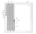
図6は、圃場内を目標経路に沿って自動で走行する作業車両100の例を模式的に示す図である。この例において、圃場は、作業車両100が作業機300を用いて作業を行う作業領域70と、圃場の外周縁付近に位置する枕地80とを含む。圃場の地図上でどの領域が作業領域70および枕地80に該当するかは、ユーザによって事前に設定され得る。この例における目標経路は、並列する複数の主経路P1と、複数の主経路P1を接続する複数の旋回経路P2とを含む。主経路P1は作業領域70内に位置し、旋回経路P2は枕地80内に位置する。図6に示す各主経路P1は直線状の経路であるが、各主経路P1は曲線状の部分を含んでいてもよい。図6における破線は、作業機300の作業幅を表している。作業幅は、予め設定され、記憶装置170に記録される。作業幅は、ユーザが操作端末200を操作することによって設定され、記録され得る。あるいは、作業幅は、作業機300を作業車両100に接続したときに自動で認識され、記録されてもよい。複数の主経路P1の間隔は、作業幅に合わせて設定され得る。目標経路は、自動運転が開始される前に、ユーザの操作に基づいてECU185が作成する。目標経路は、例えば圃場内の作業領域70の全体をカバーするように作成され得る。作業車両100は、図6に示すような目標経路に沿って、作業の開始地点から作業の終了地点まで、往復を繰り返しながら自動で走行する。なお、図6に示す目標経路は一例に過ぎず、目標経路の定め方は任意である。 [2-1. Automatic driving operation]
FIG. 6 is a diagram showing a schematic example of a
枕地80での旋回時に、予め記録された一連の動作を作業車両100が実行するように設定することもできる。この一連の動作を規定するプログラムを、本明細書において「動作シーケンス」と称する。動作シーケンスは、ユーザによって設定され、記憶装置170に記録され得る。制御装置180は、作業車両100が旋回経路に沿って旋回するとき、予め記録された動作シーケンスに従って作業車両100に一連の動作を実行させることができる。主経路P1の端部で枕地旋回を開始するとき(フィールドアウト時)と、枕地旋回を終了して次の主経路P1に沿って走行を開始するとき(フィールドイン時)とで、それぞれ異なる動作シーケンスを記録することができる。動作シーケンスとして、例えば以下のような動作を記録することができる。
・3点リンクの上昇/下降
・PTO回転のオン/オフ
・デフロックのオン/オフ
・4WD/2WDの切り替え
・エンジン回転数の増加/低下
・変速装置の切り替え It is also possible to set the
- Raising/lowering the three-point linkage - Turning the PTO on/off - Turning the differential lock on/off - Switching between 4WD/2WD - Increasing/reducing engine speed - Switching the transmission
制御システム160は、枕地旋回時に実行される一連の動作を管理する枕地管理システム(Headland Management System: HMS)としての機能を有する。一連の動作は、旋回開始時に行われるフィールドアウト動作と、旋回終了時に行われるフィールドイン動作とを含み得る。フィールドアウト動作は、例えば、作業車両100に連結される作業機300の上昇、作業機300への動力出力の停止、作業車両100が備えるデフロック機能の停止、二輪駆動(2WD)モードから四輪駆動(4WD)モードへの切り替え、および作業車両100のエンジン回転数の低下のうちの少なくとも1つの動作を含み得る。フィールドイン動作は、例えば、作業機300の降下、作業機300への動力出力の開始、デフロック機能の開始、四輪駆動モードから二輪駆動モードへの切り替え、およびエンジン回転数の上昇のうちの少なくとも1つの動作を含み得る。制御装置180は、一連の動作の内容をユーザに設定させるための設定画面を操作端末200などの表示装置に表示させてもよい。制御装置180は、設定された一連の動作の内容に基づく動作シーケンスを記憶装置170に記憶させる。The
制御装置180は、枕地80での旋回時に、予め記録された動作シーケンスに従って作業機300の動作を制御する。これにより、枕地80での自動旋回を円滑に実行することができる。制御装置180は、枕地80での旋回時だけでなく、呼び出し端末400から呼び出しを受けた場合に作業領域70内で旋回する場合も、フィールドアウト時と同様に、作業機300の上昇、および作業機300への動力出力の停止などの動作を行ってもよい。When turning on the
次に、制御装置180による自動運転時の制御の例を説明する。Next, we will explain an example of control during automatic operation by the
図7は、制御装置180によって実行される自動運転時の操舵制御の動作の例を示すフローチャートである。制御装置180は、作業車両100の走行中、図7に示すステップS121からS125の動作を実行することにより、自動操舵を行う。速度に関しては、例えば予め設定された速度に維持される。制御装置180は、作業車両100の走行中、測位装置110によって生成された作業車両100の位置を示すデータを取得する(ステップS121)。次に、制御装置180は、作業車両100の位置と、目標経路との偏差を算出する(ステップS122)。偏差は、その時点における作業車両100の位置と、目標経路との距離を表す。制御装置180は、算出した位置の偏差が予め設定された閾値を超えるか否かを判断する(ステップS123)。偏差が閾値を超える場合、制御装置180は、偏差が小さくなるように、駆動装置140に含まれる操舵装置の制御パラメータを変更することにより、操舵角を変更する。ステップS123において偏差が閾値を超えない場合、ステップS124の動作は省略される。続くステップS125において、制御装置180は、動作終了の指令を受けたか否かを判断する。動作終了の指令は、例えばユーザが遠隔操作で自動運転の停止を指示したり、作業車両100が目的地に到達したりした場合に出され得る。動作終了の指令が出されていない場合、ステップS121に戻り、新たに計測された作業車両100の位置に基づいて、同様の動作を実行する。制御装置180は、動作終了の指令が出されるまで、ステップS121からS125の動作を繰り返す。上記の動作は、制御装置180におけるECU182、184によって実行される。Figure 7 is a flowchart showing an example of the operation of steering control during automatic driving executed by the
図7に示す例では、制御装置180は、測位装置110によって特定された作業車両100の位置と目標経路との偏差のみに基づいて駆動装置140を制御するが、方位の偏差もさらに考慮して制御してもよい。例えば、制御装置180は、測位装置110によって特定された作業車両100の向きと、目標経路の方向との角度差である方位偏差が予め設定された閾値を超える場合に、その偏差に応じて駆動装置140の操舵装置の制御パラメータ(例えば操舵角)を変更してもよい。In the example shown in FIG. 7, the
以下、図8Aから図8Dを参照しながら、制御装置180による操舵制御の例をより具体的に説明する。Below, an example of steering control by the
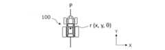
図8Aは、目標経路Pに沿って走行する作業車両100の例を示す図である。図8Bは、目標経路Pから右にシフトした位置にある作業車両100の例を示す図である。図8Cは、目標経路Pから左にシフトした位置にある作業車両100の例を示す図である。図8Dは、目標経路Pに対して傾斜した方向を向いている作業車両100の例を示す図である。これらの図において、測位装置110によって計測された作業車両100の位置および向きを示すポーズがr(x,y,θ)と表現されている。(x,y)は、地球に固定された2次元座標系であるXY座標系における作業車両100の基準点の位置を表す座標である。図8Aから図8Dに示す例において、作業車両100の基準点はキャビン上のGNSSアンテナが設置された位置にあるが、基準点の位置は任意である。θは、作業車両100の計測された向きを表す角度である。図示されている例においては、目標経路PがY軸に平行であるが、一般的には目標経路PはY軸に平行であるとは限らない。Figure 8A is a diagram showing an example of a
図8Aに示すように、作業車両100の位置および向きが目標経路Pから外れていない場合には、制御装置180は、作業車両100の操舵角および速度を変更せずに維持する。As shown in FIG. 8A, if the position and orientation of the
図8Bに示すように、作業車両100の位置が目標経路Pから右側にシフトしている場合には、制御装置180は、作業車両100の走行方向が左寄りに傾き、経路Pに近付くように操舵角を変更する。このとき、操舵角に加えて速度も併せて変更してもよい。操舵角の大きさは、例えば位置偏差Δxの大きさに応じて調整され得る。As shown in FIG. 8B, when the position of the
図8Cに示すように、作業車両100の位置が目標経路Pから左側にシフトしている場合には、制御装置180は、作業車両100の走行方向が右寄りに傾き、経路Pに近付くように操舵角を変更する。この場合も、操舵角に加えて速度も併せて変更してもよい。操舵角の変化量は、例えば位置偏差Δxの大きさに応じて調整され得る。As shown in FIG. 8C, when the position of the
図8Dに示すように、作業車両100の位置は目標経路Pから大きく外れていないが、向きが目標経路Pの方向とは異なる場合は、制御装置180は、方位偏差Δθが小さくなるように操舵角を変更する。この場合も、操舵角に加えて速度も併せて変更してもよい。操舵角の大きさは、例えば位置偏差Δxおよび方位偏差Δθのそれぞれの大きさに応じて調整され得る。例えば、位置偏差Δxの絶対値が小さいほど方位偏差Δθに応じた操舵角の変化量を大きくしてもよい。位置偏差Δxの絶対値が大きい場合には、経路Pに戻るために操舵角を大きく変化させることになるため、必然的に方位偏差Δθの絶対値が大きくなる。逆に、位置偏差Δxの絶対値が小さい場合には、方位偏差Δθをゼロに近づけることが必要である。このため、操舵角を決定するための方位偏差Δθの重み(すなわち制御ゲイン)を相対的に大きくすることが妥当である。8D, when the position of the
作業車両100の操舵制御および速度制御には、PID制御またはMPC制御(モデル予測制御)などの制御技術が適用され得る。これらの制御技術を適用することにより、作業車両100を目標経路Pに近付ける制御を滑らかにすることができる。Control techniques such as PID control or MPC control (model predictive control) can be applied to the steering control and speed control of the
なお、走行中に1つ以上の障害物センサ130によって障害物が検出された場合には、制御装置180は、作業車両100を停止させる。制御装置180は、障害物が検出された場合に障害物を回避するように駆動装置140を制御してもよい。If an obstacle is detected by one or
[2-2.呼び出し地点への移動]
次に、作業車両100が自動運転を行っているときに呼び出し端末400から呼び出しを受けた場合の動作の例を説明する。 [2-2. Moving to the calling point]
Next, an example of the operation when
本実施形態における作業車両100は、呼び出し端末400から呼び出しを受けると、作業を中断して呼び出し端末400の呼び出し地点に移動する。このとき、作業車両100は、作業が完了している作業済み領域を踏むことなく呼び出し地点に到達する経路である呼び出し経路に沿って移動する。呼び出し経路は、呼び出し地点と、呼び出しを受けたときの作業車両100と、作業済み領域との位置関係に基づいて作成される。When the
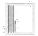
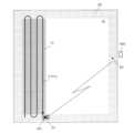
図9Aは、圃場内で作業車両100が自動走行しているときに、呼び出し端末400から呼び出しを受けた状況の例を模式的に示す図である。この例において、作業車両100は、無人で作業を行いながら目標経路Pに含まれる1つの主経路P1に沿って走行している。この状態で、作業領域70の外側にいるユーザが、呼び出し端末400を用いて作業車両100を呼び出す操作を行う。この例における呼び出し端末400はスマートフォンであり、作業車両100を呼び出すためのソフトウェアが予めインストールされている。ユーザは、作業車両100による作業に必要な農業資材(種、肥料、または苗など)を補給したり、作業車両100に搭乗して手動で運転するために、呼び出し端末400を用いて作業車両100を呼び出す操作を行う。呼び出しの操作が行われると、呼び出し端末400は、GNSS受信機410から出力された呼び出し端末400の位置情報を含む呼び出し信号を作業車両100に送信する。作業車両100は、呼び出し信号を受信すると、その位置情報に基づいて呼び出し地点を決定し、呼び出し地点に向かって移動する。このとき、作業車両100は、作業が完了している作業済み領域72を踏まないように呼び出し地点に向かう呼び出し経路を作成し、呼び出し経路に沿って走行する。呼び出し経路は、制御装置180におけるECU185によって作成される。9A is a diagram showing a schematic example of a situation in which a call is received from the
呼び出し経路を作成するためには、作業済み領域72の情報が必要である。そこで、本実施形態におけるECU185は、作業車両100が目標経路Pに沿って走行している間、作業済み領域72を記憶装置170に記憶させる。作業済み領域72は、測位装置110によって特定された作業車両100の位置と、予め設定された作業車両100の作業幅とに基づいて計算され得る。ECU185は、作業車両100の走行中、作業済み領域72の範囲を示す情報(例えば、地図上の座標範囲の情報など)を記憶装置170に記憶させる。なお、作業済み領域72の記録は、ECU185に限らず、他のECUまたは外部のサーバなどの、他のコンピュータによって行われてもよい。In order to create a call route, information on the worked
ECU185は、呼び出し経路を作成するとき、まず移動先である呼び出し地点を確定する。ECU185は、呼び出し端末400から送信された呼び出し信号に含まれる位置情報が示す地点そのものを呼び出し地点としてもよい。しかし、呼び出し端末400におけるGNSS受信機410の測位結果には一般に誤差が含まれ、場合によっては測位の誤差が数メートルまたはそれ以上になることもある。したがって、呼び出し信号に含まれる位置情報をそのまま用いた場合、呼び出し端末400の実際の位置から大きく離れた地点が呼び出し地点として決定される可能性がある。例えば、作業済み領域72の内側の地点、または圃場の外側の道路上の地点が呼び出し地点として決定される可能性がある。そのような事態を避けるため、ECU185は、呼び出し信号に含まれる位置情報が示す位置が作業済み領域72の内側または道路上の位置を示す場合、位置情報が示す位置を、圃場の内側かつ作業済み領域72の外側の位置に補正し、補正した位置を呼び出し地点の位置としてもよい。これにより、GNSS受信機410の測位の誤差が大きい場合でも、呼び出し地点を適切な位置に設定することができる。そのような補正を行った場合、ECU185は、呼び出し地点を補正したことを示す通知を呼び出し端末400に送信してもよい。When creating a call route, the
ECU185は、呼び出し地点を決定すると、呼び出し地点の位置、測位装置110によって特定された作業車両100の位置、および記憶装置170に記憶された作業済み領域72の情報に基づいて呼び出し経路を決定する。ECU185は、呼び出しを受けたときの作業車両100の位置から作業済み領域72を経由せずに呼び出し地点に向かう経路を呼び出し経路として決定する。When the
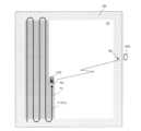
図9Bは、作業車両100が呼び出し経路P3に沿って呼び出し地点B2に向かって移動する状況の例を示す図である。この例において、呼び出し地点B2は、枕地80のうち、呼び出し端末400の近傍の枕地80内の地点に決定されている。呼び出しを受けたときの作業車両100の位置B1と呼び出し地点B2との間には、作業済み領域72がある。言い換えれば、呼び出しを受けたときの作業車両100の位置B1と呼び出し地点B2とを結ぶ直線(図9Bにおける点線)が作業済み領域72と重なる。このような場合、ECU185は、位置B1から、作業済み領域72の外周に沿って呼び出し地点B2に向かう経路を呼び出し経路P3として決定する。Figure 9B is a diagram showing an example of a situation in which the
ECU185は、例えば、作業済み領域72の外周に沿って最短で呼び出し地点B2に到達できる経路を呼び出し経路P3として決定するように構成され得る。図9Bの例においては、呼び出しを受けたときの作業車両100の位置B1から、走行中の主経路P1に沿って直進した後、作業済み領域72の外周に沿って呼び出し地点B2に向かう経路が呼び出し経路P3として決定されている。図10Bに示す呼び出し経路P3は、位置B1から主経路P1に沿って枕地80まで延びる第1の直線P3aと、第1の直線P3aに接する第1の円C1の弧と、第1の円C1に接し作業領域70と枕地80との境界線にほぼ平行に延びる第2の直線P3bと、第2の直線P3bに接する第2の円C2の弧と、第2の円C2に接し呼び出し地点B2まで延びる第3の直線P3cとを結ぶことによって作成される。第1の円C1および第2の円C2の半径は、例えば作業車両100の旋回可能な最小の半径などの所定の値に設定され得る。作業領域70と枕地80との境界線と直線P3bとの距離dは、例えば枕地80の幅の半分などの所定の値に設定され得る。The
図9Bの例における呼び出し経路P3は、目標経路Pのうち、作業車両100が呼び出された時点で未走行の部分、すなわち作業車両100の進行方向側に位置する部分を含んでいる。このように、ECU185は、目標経路Pのうち、呼び出しを受けたときに作業車両100の進行方向側に位置する部分を含む経路を呼び出し経路P3として決定してもよい。このような経路の決定方法は、例えば特許文献1に開示されている従来の方法とは大きく異なる。特許文献1においては、未収穫の作物(例えば稲)が収穫機に踏まれることがないように、未作業の領域を避けて排出または補給のための経路が決定される。これに対し、本実施形態では、作業済み領域72を避けて呼び出し経路P3が決定され、呼び出し経路P3が未作業の領域を含んでいてもよい。本実施形態では、作業済み領域72を除く領域に呼び出し経路P3が作成されるため、作業済み領域72を作業車両100が踏むことによって作業の効果が損なわれることを回避することができる。9B includes the portion of the target route P that is not traveled at the time when the
本実施形態では、作業車両100が呼び出し経路P3に沿った走行を開始するとき、制御装置180は、作業機300による作業を停止させる。例えば、制御装置180は、PTOの回転を停止し、3点リンクを上昇させることにより、作業機300による作業を停止させる。このような動作に代えて、作業車両100は、呼び出し経路P3のうち、目標経路Pにおける主経路P1と重複する部分を走行している間は、作業機300を停止せずに作業を継続してもよい。例えば図9Bの例において、作業車両100が呼び出しを受けた後、主経路P1に沿って走行する区間の少なくとも一部において、作業を継続してもよい。そのような動作により、作業効率を向上させることができる。In this embodiment, when the
本実施形態におけるECU185は、呼び出し地点B2と、呼び出しを受けた作業車両100の位置B1と、作業済み領域72との位置関係に応じて異なる方法で呼び出し経路を作成する。以下、呼び出し経路の作成方法のいくつかの例を説明する。In this embodiment, the
図10Aは、呼び出しを受けた作業車両100の位置B1と呼び出し地点B2との間に作業済み領域72がある場合の他の例を示す図である。図10Aの例は、図9Aの例と比較して、呼び出し端末400の位置が作業車両100の進行方向の反対側に寄っている。このような場合、図9Bに示す方法と同様の方法で呼び出し経路を作成すると、作業車両100が呼び出し地点B2に到達するまでに長い時間を要することになる。そこで、この例では、図10Bに示すように、ECU185は、呼び出しを受けたときの作業車両100の位置B1から作業済み領域72がある側とは反対の側に旋回して逆方向に直進した後、作業済み領域72の外周に沿って呼び出し地点B2に向かう経路を呼び出し経路P3として決定する。この例においても、図9Bの例と同様、ECU185は、複数の直線と複数の円弧とを組み合わせた経路を呼び出し経路P3として作成する。具体的には、図10Bに示す呼び出し経路P3は、呼び出しを受けた作業車両100の位置B1から主経路P1に沿って比較的短い所定の距離(例えば1m)だけ延びる第1の直線P3aと、第1の直線P3aに接する所定の半径の第1の円C1の弧と、第1の円C1の弧に沿って180°旋回した点から旋回前の作業車両100の進行方向の反対側の枕地80まで延びる第2の直線P3bと、第2の直線P3bに接する所定の半径の第2の円C2の弧と、第2の円C2に接し作業領域70と枕地80との境界線に平行に延びる第3の直線P3cと、第3の直線P3cに接する第3の円C3の弧と、第3の円C3に接し呼び出し地点B2まで延びる第4の直線P3dとを結ぶことによって作成され得る。Figure 10A is a diagram showing another example in which the worked
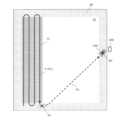
図11Aは、呼び出しを受けた作業車両100の位置B1と呼び出し地点B2との間に作業済み領域72がない場合の例を示す図である。この場合、図11Bに示すように、ECU185は、呼び出しを受けたときの作業車両100の位置B1から呼び出し地点B2に向かう直線状の経路P3を呼び出し経路として決定する。例えば、呼び出しを受けたときの作業車両100の位置B1から主経路P1に沿って比較的短い所定の距離(例えば1m)だけ延びる直線P3aと、その直線P3aに接する所定の半径の円C1の弧と、その円C1に接し呼び出し地点B2まで延びる直線P3bとを結んだ経路が呼び出し経路P3として決定され得る。Figure 11A is a diagram showing an example of a case where there is no completed
以上の各例では、作業車両100は、作業領域70内を直線状の主経路P1に沿って走行しているときに呼び出しを受けている。このような例に限らず、作業車両100は、枕地80で旋回しているときに呼び出しを受けることもある。以下、そのような場合における呼び出し経路の作成方法のいくつかの例を説明する。In each of the above examples, the
図12Aは、作業車両100が枕地80で旋回しているときに呼び出し端末400から呼び出された場合の例を示す図である。このような例では、ECU185は、作業車両100が旋回を終了して次の主経路P1に沿った走行を開始してから呼び出し経路の作成を行う。図12Aの例では、作業車両100の位置B1と呼び出し地点B2との間に作業済み領域72があり、呼び出し地点B2が作業車両100から比較的遠い。このような場合、ECU185は、図12Bに示すように、次の主経路P1に沿って反対側の枕地80まで直進し、作業済み領域72の外周に沿って呼び出し地点B2に向かう経路を呼び出し経路P3として決定する。この場合の経路の作成方法は、図9Bに示す例と同様である。Figure 12A is a diagram showing an example of a case where the
図13Aは、作業車両100が枕地80で旋回しているときに呼び出し端末400から呼び出された場合の他の例を示す図である。この例では、作業車両100の位置B1と呼び出し地点B2との間に作業済み領域72があり、呼び出し地点B2が作業車両100に比較的近い。この場合も、ECU185は、作業車両100が旋回を終了して次の主経路P1に沿った走行を開始してから呼び出し経路の作成を行う。ECU185は、図13Bに示すように、一旦次の主経路P1に沿って所定距離(例えば1m)だけ走行した後、作業済み領域72がある側の反対側に旋回して逆方向に直進した後、作業済み領域72の外周に沿って呼び出し地点B2に向かう経路を呼び出し経路P3として決定する。この場合の経路の作成方法は、図10Bに示す例と同様である。Figure 13A is a diagram showing another example of a case where the
なお、図13Bの例のように、呼び出し地点B2が呼び出しを受けた作業車両100の位置B1に近く、作業車両100の後部側に呼び出し地点B2がある場合、作業車両100は後進すなわちバック走行して呼び出し地点に向かってもよい。例えば、ECU185は、図13Cに示すように、作業車両100が後進して呼び出し地点B2に向かう呼び出し経路P3を作成してもよい。この例においても、複数の直線と円弧とを接続することによって呼び出し経路P3が作成され得る。この場合、ECU184は、作業車両100を呼び出し経路P3に沿って後進させることによって呼び出し地点B2に移動させる。このように、制御装置180は、呼び出しを受けた作業車両100の位置と呼び出し地点B2との相対位置および作業車両100の向きが所定の条件を満たす場合に、作業車両100を後進させることによって呼び出し地点B2に向けて移動させてもよい。これにより、呼び出し地点B2に到達するまでの時間を短縮することができる。Note that, as in the example of FIG. 13B, when the call point B2 is close to the position B1 of the
図14Aは、作業車両100が枕地80で旋回しているときに呼び出し端末400から呼び出された場合のさらに他の例を示す図である。この例では、作業車両100の位置B1と呼び出し地点B2との間に作業済み領域72が存在しない。このような場合、ECU185は、図14Bに示すように、位置B1から位置B2に向かう直線的な経路を呼び出し経路P3として決定する。この場合の経路の作成方法は、図11Bに示す例と同様である。Figure 14A shows yet another example of a case where a call is made from the
以上のような動作により、作業車両100は、作業済み領域72を踏むことなく、呼び出し地点B2に短時間で到達することができる。なお、以上の各例における呼び出し経路P3の作成方法は例示にすぎない。呼び出し経路P3は、上記とは異なる方法で作成されてもよい。By performing the above operations, the
次に、図15を参照しながら、ECU185による呼び出し経路の作成方法の例をより詳細に説明する。Next, an example of how the
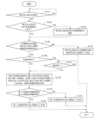
図15は、ECU185による呼び出し経路の作成方法の例を示すフローチャートである。この例において、ECU185は、作業車両100が自動で作業走行を行っている間、通信装置190が呼び出し信号を受信したか否かを判断する(ステップS141)。呼び出し信号が受信された場合、ECU185は、呼び出し信号に含まれる位置情報が示す呼び出し地点が走行可能領域内にあるか否かを判断する(ステップS142)。走行可能領域は、圃場内で作業車両100の走行が許容されている領域を意味する。走行可能領域は、例えば圃場の内部でかつ作業済み領域の外側の領域のうち、圃場の外周部および作業済み領域の双方から、ある一定の距離以上離れている領域であり得る。一定の距離は、例えば作業車両100の作業幅の半分よりも大きい値であり得る。走行可能距離は、例えば自動運転を開始する前に予め設定され得る。呼び出し地点が走行可能領域内にある場合、ステップS144に進む。呼び出し地点が走行可能領域内にない場合、ステップS143に進む。ステップS143において、ECU185は、呼び出し地点を走行可能領域内の地点に補正する。補正は、例えば元の呼び出し地点と補正後の呼び出し地点との距離が最小限になるように行われ得る。ステップS143の後、ステップS144に進む。FIG. 15 is a flowchart showing an example of a method for creating a call route by the
ステップS144において、ECU185は、作業車両100の位置と呼び出し地点との間に作業済み領域があるか否かを判断する。例えば、ECU185は、測位装置110によって特定された作業車両100の位置と呼び出し地点とを結ぶ所定の幅(例えば作業幅以上の幅)の直線が作業済み領域と重なるか否かを判断する。当該直線が作業済み領域と重なる場合、作業車両100の位置と呼び出し地点との間に作業済み領域があると判断され得る。作業車両100の位置と呼び出し地点との間に作業済み領域がない場合、ECU185は、作業車両100の位置から呼び出し地点まで向かう直線的な経路を呼び出し経路として決定する(ステップS145)。ここで、「直線的な経路」は、完全に直線的な経路に限らず、図11Bまたは図14Bに示すような、部分的に曲線または折れ線を含む経路であってもよい。ECU185は、作業車両100が作業済み領域を踏まないように、呼び出し経路における直線部分の角度、長さ、および曲線部分の位置および曲率半径等を調整してもよい。In step S144, the
作業車両100の位置と呼び出し地点との間に作業済み領域がある場合、ECU185は、作業車両100が枕地で旋回しているか、主経路に沿って走行しているかを判断する(ステップS146)。作業車両100が主経路に沿って走行している場合、ステップS148に進む。作業車両100が枕地で旋回している場合、作業車両100が旋回を終え、主経路に沿って走行し始めるまで待機する(ステップS147)。作業車両100が旋回を終え、主経路に沿って走行し始めると、ステップS148に進む。If there is a completed work area between the position of the
ステップS148において、ECU185は、作業車両100の進行方向側の枕地まで進んでから作業済み領域の外周に沿って呼び出し地点に向かう第1の経路と、旋回して進行方向の反対側の枕地に戻ってから作業済み領域の外周に沿って呼び出し地点に向かう第2の経路とを作成し、両者の移動時間を計算する。第1の経路は、例えば図9Bおよび図12Bに示す呼び出し経路P3のような経路である。第2の経路は、例えば図10Bおよび図13Bに示す呼び出し経路P3のような経路である。ECU185は、第1の経路の移動時間と第2の経路の移動時間とを比較する(ステップS149)。第1の経路の移動時間が第2の経路の移動時間以下である場合、ECU185は、第1の経路を呼び出し経路として決定する(ステップS150)。逆に、第1の経路の移動時間が第2の経路の移動時間よりも長い場合、ECU185は、第2の経路を呼び出し経路として決定する(ステップS151)。In step S148, the
以上の動作により、ECU185は、呼び出しを受けたときの作業車両100の位置、呼び出し地点の位置、および作業済み領域に応じて適切な呼び出し経路を作成することができる。このような動作によって作成された呼び出し経路に沿って走行することにより、作業車両100は、作業済み領域を踏むことなく、比較的短時間で呼び出し地点に到達することができる。By performing the above operations, the
なお、図15に示す経路の作成方法は一例にすぎず、適宜変形が可能である。例えば、ステップS148からS151の動作の代わりに、第1の経路のみを作成してそれを呼び出し経路として決定してもよい。あるいは、図13Cの例のように、所定の条件を満たす場合に後進して呼び出し地点に向かう経路を呼び出し経路として決定するようにしてもよい。Note that the method of creating the route shown in FIG. 15 is merely an example and can be modified as appropriate. For example, instead of the operations from steps S148 to S151, only the first route may be created and determined as the call route. Alternatively, as in the example of FIG. 13C, a route that reverses and heads toward the call point when a certain condition is met may be determined as the call route.
作業車両100が呼び出し経路に沿って移動している間にユーザが呼び出し地点を変更できるようにシステムが構成されていてもよい。例えば、作業車両100が呼び出し経路に沿って移動している間に呼び出し端末400を持ったユーザが移動し、移動先の地点で再度呼び出し操作を行うことによって呼び出し地点を変更できるようにシステムが構成されていてもよい。その場合、ECU185は、呼び出し経路を作成した後、再度呼び出し信号を受信したとき、例えば図15に示す動作を再度実行し、呼び出し経路を修正するように構成され得る。修正後の呼び出し経路も、作業済み領域を経由しないように作成される。The system may be configured to allow the user to change the call location while the
作業車両100は、呼び出し地点に到達すると停止する。呼び出し地点に到達する前に呼び出し端末400のユーザ、またはその他の障害物を障害物センサ130が検出した場合も作業車両100は停止する。障害物を検出して停止した場合、障害物が検出範囲外に出ると作業車両100は再び呼び出し地点に向けて移動を開始してもよい。前述の各例において、作業車両100が停止するときの向きは、呼び出し経路の終端部分の方向に依存する。この作業車両100が停止するときの向きをユーザが指定できるようにしてもよい。例えば、資材の補給などの作業を行うのに適した向き、または搭乗しやすい向きで作業車両100が停止するように、ユーザが呼び出し端末400を操作して作業車両100の停止時の向きを指定できるようにしてもよい。停止時の向きの指定は、作業車両100を呼び出す前に行われてもよいし、作業車両100が呼び出し経路に沿って走行している最中に行われてもよい。ユーザが停止時の向きを指定する操作を行った場合、呼び出し端末400は、呼び出し地点の位置情報だけでなく、呼び出し地点における作業車両100の向きを指定する情報を含む呼び出し信号を作業車両100に送信する。ECU185は、当該情報が示す向きで作業車両100を停止させるように呼び出し経路を作成する。The
上記の各例では、ECU185は、呼び出し端末400のGNSS受信機410が決定した位置、またはその位置から補正した位置を呼び出し地点の位置として決定する。すなわち、ECU185は、呼び出し端末400自身の位置情報に基づいて呼び出し地点の位置を決定する。しかし、本開示は、そのような形態に限定されない。例えば、ユーザが呼び出し端末400を操作して所望の位置を呼び出し地点として指定できるようにしてもよい。In each of the above examples, the
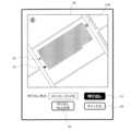
図16Aは、ユーザが呼び出し地点を指定して作業車両100を呼び出すことを可能にするグラフィカルユーザインターフェース(GUI)の一例を示す図である。図16Aに示すような表示画面が呼び出し端末400の表示装置430に表示され得る。この表示画面には、圃場の地図90(例えば航空写真)と、作業車両100に呼び出しを指示するボタン91とが含まれている。ユーザは、圃場の地図90上で、所望の地点をタップまたはクリックするなどの操作により、呼び出し地点を指定できる。図16Aの例では、指定された呼び出し地点を示すマーク92と、現在地を示すマーク93とが地図90上に表示され、指定された呼び出し地点の座標(例えば緯度および経度)も表示されている。ユーザは、呼び出し地点を指定した後、ボタン91を押すことにより、作業車両100を呼び出し地点に呼び出すことができる。この例においては、呼び出し端末400は、ボタン91が押されると、指定された呼び出し地点の位置情報(例えば緯度および経度などの座標値)を含む呼び出し信号を作業車両100に送信する。作業車両100の制御装置180は、呼び出し信号を受けて、呼び出し経路を作成し、呼び出し経路に沿った走行を開始させる。16A is a diagram showing an example of a graphical user interface (GUI) that allows a user to specify a call point and call the
呼び出し経路が経由する1つ以上の通過地点をユーザが指定できるようにシステムが構成されていてもよい。例えば、図16Aに示すようなGUIに、さらに通過地点を指定できる機能が実装されていてもよい。その場合、呼び出し端末400は、呼び出し地点の位置情報に加えて、1つ以上の通過地点を示す情報を含む呼び出し信号を作業車両100に送信する。作業車両100の制御装置180は、通過地点を経由するように呼び出し経路を作成し、1つ以上の通過地点を経由して呼び出し地点に向かうように作業車両100を制御する。The system may be configured to allow the user to specify one or more pass points through which the call route passes. For example, a function for further specifying pass points may be implemented in a GUI such as that shown in FIG. 16A. In this case, the
図16Bは、呼び出しの操作が行われた後、呼び出し地点を変更することを可能にするGUIの一例を示す図である。ユーザが呼び出しの操作を行い、作業車両100が呼び出し経路に沿って走行を開始した後、図16Bに示すような画面が呼び出し端末400に表示されてもよい。ユーザは、指定した呼び出し地点を変更することができる。ユーザは、圃場の地図90上で、変更後の呼び出し地点に相当する位置をタップするなどの操作を行い、「呼び出し地点変更」のボタン96を押すことにより、呼び出し地点を変更することができる。呼び出し端末400は、ボタン96が押されると、変更後の呼び出し地点の位置情報を含む呼び出し信号を作業車両100に送信する。作業車両100のECU185は、その呼び出し信号を受けて、変更後の呼び出し地点に向かうように呼び出し経路を修正する。ECU184は、修正された呼び出し経路に沿って変更後の呼び出し地点に作業車両100が向かうように制御する。図16Bに示す表示画面にはキャンセルボタン95も含まれている。ユーザは、キャンセルボタン95を押すことにより、作業車両100の呼び出しをキャンセルすることもできる。ボタン95が押された場合、作業車両100は、呼び出し地点に向かうことを停止する。この場合、作業車両100は、作業走行中に呼び出しを受けた地点に自動で戻って作業走行を再開してもよいし、その場で停止してユーザからの指示を待ってもよい。16B is a diagram showing an example of a GUI that allows the call location to be changed after a call operation is performed. After the user performs a call operation and the
作業車両100は、呼び出し地点での補給などの作業が完了した後、呼び出しを受けて作業走行を中断した地点に自動で戻り、作業走行を再開するように構成されていてもよい。例えば、ユーザが補給などの作業を終え、呼び出し端末400を用いて作業走行を再開させる操作をすることにより、作業車両100が作業走行を再開するように構成されていてもよい。The
図16Cは、作業車両100に作業走行を再開させるためのGUIの例を示す図である。この例では、作業車両100が呼び出し地点に到達すると、図16Cに示すような画面が呼び出し端末400に表示される。ユーザは、「作業走行再開」ボタン97を押すことにより、作業車両100に作業走行の再開を指示することができる。ボタン97が押されると、呼び出し端末400は、作業車両100に、作業走行を再開させる信号(以下、「復帰信号」と称する。)を送信する。作業車両100の制御装置180は、この復帰信号を受信すると、作業車両100が作業走行を中断した地点に戻り、作業走行を再開するように駆動装置140を制御する。Figure 16C is a diagram showing an example of a GUI for causing the
この機能を実装する場合、制御装置180は、作業車両100が農作業を中断したとき、その地点(以下、「中断地点」と称する。)の位置を記憶装置170に記憶させる。制御装置180は、呼び出し信号に応答して作業車両100に呼び出し経路に沿った移動を開始させるとき、または呼び出し経路に沿って作業車両100を移動させている途中で、作業車両100に農作業を中断させる。その中断のタイミングで、制御装置180は、中断地点の位置を記憶装置170に記憶させる。制御装置180のECU185は、作業車両100が呼び出し地点に呼び出された後、復帰信号を受けると、作業済み領域を経由せずに中断地点まで戻る復帰経路を作成する。復帰経路は、例えば呼び出し経路に沿って逆向きに進む経路であり得る。呼び出し地点で旋回して呼び出し経路に沿って逆向きに前進することが難しい場合は、呼び出し経路をそのまま後進して中断地点まで戻ってもよい。制御装置180のECU184は、復帰経路に沿って作業車両100を前進または後進させて中断地点まで移動させ、中断地点から作業車両100に作業走行を再開させるように駆動装置140を制御する。なお、作業車両100が復帰経路に沿って中断地点に戻り、農作業を再開するとき、作業済み領域を全く踏まずに中断地点に戻ることは難しい。したがって、復帰経路に沿って移動する作業車両100がわずかに作業済み領域を踏むことは許容される。この点は、作業車両100が呼び出し経路に沿って移動するときも同様である。When this function is implemented, the
図17は、呼び出し地点B2から復帰経路P4に沿って中断地点B3に戻る作業車両100の例を示す図である。この例では、作業車両100は、位置B1で呼び出された後、呼び出し地点B2に向かうために呼び出し経路P3に沿って移動しているときも、目標経路Pにおける主経路P1に沿って移動している間は作業を継続する。作業車両100は、呼び出し地点B2において補給などの作業が終了した後、復帰信号を受けて復帰経路P4を作成し、復帰経路P4に沿って中断地点B3まで移動する。なお、この例では、作業車両100による作業が主経路P1の列の途中で中断せずにその列の最後まで行われている。このような場合は、図17に示すように次の列の開始点が中断地点B3として記録される。図17の例では、図9Bの例と比較して呼び出し地点B2におけるスペースが広く、作業車両100が旋回するのに十分なスペースがある。この例とは異なり、旋回するのに十分なスペースがない場合は、例えば図18に示すように、制御装置180は、呼び出し経路P3の方向を逆転させた復帰経路P4を作成し、復帰経路P4に沿って作業車両100を後進すなわちバック走行させることにより、中断地点B3に移動させてもよい。なお、図18の例では、作業車両100は位置B1で呼び出しを受けたときに作業を中断しており、中断地点B3の位置は位置B1と一致している。Figure 17 is a diagram showing an example of a
以上の各例では、1つの圃場内で1台の作業車両100のみが作業走行を行うが、1つの圃場内で複数の作業車両が同時に作業走行を行ってもよい。その場合、制御装置180におけるECU185は、呼び出し信号を受けたとき、他の作業車両によって農作業が行われた他の作業済み領域がある場合は、いずれの作業済み領域をも経由せずに呼び出し地点に向かうように呼び出し経路を決定する。以下、そのような場合の例を説明する。In each of the above examples, only one
図19は、1つの圃場内で第1の作業車両100Aおよび第2の作業車両100Bが同時に作業走行を行っている状況の例を模式的に示す図である。この例において、第1の作業車両100Aおよび第2の作業車両100Bは、圃場の反対側で往復しながら作業を行っている。このような状況で、第1の作業車両100Aが枕地80で旋回している途中で呼び出し端末400から呼び出しを受けたとする。この場合、図14Bに示す例とは異なり、呼び出しを受けた第1の作業車両100Aの位置B1から直線的な経路で呼び出し地点B2に向かうと、第2の作業車両100Bが作業を行った作業済み領域72Bを経由することになる。このような場合、第1の作業車両100Aの制御装置180は、第1の作業車両100Aが作業を行った作業済み領域72Aだけでなく、第2の作業車両100Bが作業を行った作業済み領域72Bも経由しないように呼び出し経路P3を作成する。図19の例では、最も短い時間で呼び出し地点B2に到達できる枕地80に沿った逆L字型の呼び出し経路P3が作成される。Figure 19 is a diagram showing a schematic example of a situation in which the
(他の実施形態)
次に、本開示の他の実施形態を説明する。 Other Embodiments
Next, another embodiment of the present disclosure will be described.
上記の実施形態では、作業車両100の制御装置180が、呼び出し経路の作成と、呼び出し経路に沿って作業車両100を走行させる制御とを実行する。呼び出し経路の作成を制御装置180とは異なる装置が実行してもよい。例えば、作業車両100と通信を行うサーバなどの外部のコンピュータが呼び出し経路を作成してもよい。In the above embodiment, the
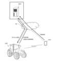
図20は、作業車両100とネットワーク40を介して通信する処理装置500が呼び出し経路を作成するシステムの構成を模式的に示す図である。この例では、作業車両100の制御装置180ではなく、外部の処理装置500が呼び出し経路を作成し、その情報を作業車両100に送信する。処理装置500は、例えばクラウドサーバなどのコンピュータであり得る。Figure 20 is a diagram that shows a schematic configuration of a system in which a
図21は、処理装置500の構成を示すブロック図である。処理装置500は、1つ以上のプロセッサ560と、記憶装置570と、通信装置590とを備える。記憶装置570は、プロセッサ560によって実行されるコンピュータプログラムを格納したメモリを含む。通信装置590は、作業車両100における通信装置190および呼び出し端末400における通信装置490と信号の送受信を行う。この実施形態では、呼び出し端末400が作業車両100の呼び出しを行うとき、呼び出し地点の位置情報を含む信号を処理装置500にネットワーク40を介して送信する。処理装置500のプロセッサ560は、当該位置情報と、作業車両100から取得した作業車両100の位置情報および作業済み領域を示す情報とに基づき、前述の実施形態と同様の方法で呼び出し経路を作成する。処理装置500の通信装置590は、その呼び出し経路の情報を作業車両100に送信する。作業車両100は、呼び出し経路に沿って呼び出し地点に移動する。処理装置500のプロセッサ560は、呼び出し経路だけでなく、作業走行のための目標経路の作成を行ってもよい。その場合、作業車両100は、図3に示す経路作成用のECU185を備えていなくてもよい。21 is a block diagram showing the configuration of the
処理装置500の代わりに、呼び出し端末400が呼び出し経路を作成してもよい。その場合、呼び出し端末400は、作業車両100の位置情報および作業済み領域の情報を、作業車両100または処理装置500から取得する。呼び出し端末400のプロセッサ460は、作業車両100の位置情報と、呼び出し地点の位置情報と、作業済み領域の情報とに基づいて、呼び出し経路を作成する。呼び出し端末400は、呼び出し地点の位置情報と、呼び出し経路の情報とを含む呼び出し信号を作業車両100に送信する。このような動作により、前述の各実施形態と同様の効果を得ることができる。Instead of the
以上の各実施形態において、呼び出し端末400の代わりに、作業車両100を監視するための監視端末が作業車両100を呼び出す動作を行ってもよい。そのような監視端末は、例えば作業車両100を監視するユーザの自宅または事業所に設けられ得る。In each of the above embodiments, instead of the calling
図22は、監視端末600が作業車両100を呼び出すシステムの例を模式的に示す図である。監視端末600は、例えばラップトップコンピュータまたはパーソナルコンピュータであり、ネットワーク40を介して作業車両100と通信を行うことができる。なお、監視端末600は、スマートフォンまたはタブレットコンピュータなどの携帯可能なコンピュータであってもよい。ユーザは、監視端末600を操作することにより、前述の各実施形態と同様に、作業車両100を所望の地点に呼び出すことができる。監視端末600の構成は、図3に示す呼び出し端末400の構成と同様である。この例では、作業車両100の構成は実施形態1における構成と同じである。なお、作業車両100の制御装置180におけるECU185の代わりに、監視端末600が呼び出し経路を作成してもよい。その場合、監視端末600は、作業車両100の位置情報および作業済み領域の情報を作業車両100から取得する。監視端末600は、呼び出し地点の位置情報、作業車両100の位置情報、および作業済み領域の情報に基づいて、呼び出し経路を作成し、その情報を作業車両100に送信する。Figure 22 is a diagram showing a schematic example of a system in which a
図23は、監視端末600が作業車両100を呼び出すシステムの他の例を模式的に示す図である。このシステムは、図20に示すシステムにおける呼び出し端末400が監視端末600に置換されたものである。このシステムでは、ユーザの操作に基づいて監視端末600が処理装置500に呼び出し地点の位置情報を送信する。処理装置500は、図20の例と同様に呼び出し経路を作成して作業車両100に送信する。この例においても、処理装置500の代わりに監視端末600が作業済み領域を作成し、作業車両100にその情報を送信してもよい。Figure 23 is a diagram showing a schematic diagram of another example of a system in which a
以上の各実施形態における作業車両100はトラクタであるが、トラクタ以外の車両または車両以外の農業機械に前述の各実施形態の技術を適用してもよい。例えば、収穫機、田植機、乗用管理機、野菜移植機、草刈機、または農業用移動ロボットなどの農業機械に、前述の各実施形態の技術を適用してもよい。The
以上の各実施形態における呼び出し経路を作成する装置、および呼び出し経路に従って農業機械の移動を制御する装置を、それらの機能を有しない農業機械に後から取り付けることもできる。そのような装置は、農業機械とは独立して製造および販売され得る。そのような装置で使用されるコンピュータプログラムも、農業機械とは独立して製造および販売され得る。コンピュータプログラムは、例えばコンピュータが読み取り可能な非一時的な記憶媒体に格納されて提供され得る。コンピュータプログラムは、電気通信回線(例えばインターネット)を介したダウンロードによっても提供され得る。The device for creating the call route in each of the above embodiments and the device for controlling the movement of the agricultural machine according to the call route can also be attached later to an agricultural machine that does not have these functions. Such devices can be manufactured and sold independently of the agricultural machine. The computer program used in such devices can also be manufactured and sold independently of the agricultural machine. The computer program can be provided, for example, by being stored in a non-transitory computer-readable storage medium. The computer program can also be provided by downloading via a telecommunications line (for example, the Internet).
以上のように、本開示は、以下の項目に記載のシステム、装置、方法、およびコンピュータプログラムを含む。As described above, the present disclosure includes the systems, devices, methods, and computer programs described in the following sections.
[項目A1]
自動運転を行う農業機械を呼び出し地点に呼び出す端末装置と、
前記呼び出し地点に向かうために前記農業機械が移動する呼び出し経路を、前記農業機械の作業済み領域を除く領域に作成する処理装置と、
を備える農業支援システム。 [Item A1]
A terminal device for calling an autonomously operated agricultural machine to a calling point;
a processing device that creates a call route along which the agricultural machine moves to travel toward the call point, in an area excluding an area where the agricultural machine has already completed work;
An agricultural support system equipped with:
[項目A2]
前記農業機械が前記呼び出し経路に沿って移動するように前記農業機械の動作を制御する制御装置をさらに備える、項目A1に記載の農業支援システム。 [Item A2]
The agricultural support system according to item A1, further comprising a control device that controls operation of the agricultural machine so that the agricultural machine moves along the call path.
[項目A3]
前記制御装置は、前記農業機械に農作業を少なくとも部分的に停止させた状態で、前記呼び出し経路に沿って前記農業機械を移動させる、項目A2に記載の農業支援システム。 [Item A3]
The agricultural support system according to item A2, wherein the control device moves the agricultural machine along the call route while causing the agricultural machine to at least partially stop farm work.
[項目A4]
前記農業機械によって農作業が行われた領域を前記作業済み領域として記憶する記憶装置をさらに備え、
前記端末装置は、前記呼び出し地点の位置情報を含む呼び出し信号を前記処理装置に送信し、
前記処理装置は、前記位置情報、および前記記憶装置に記憶された前記作業済み領域に基づいて、前記呼び出し経路を作成する、
項目A1からA3のいずれかに記載の農業支援システム。 [Item A4]
a storage device that stores an area where farm work has been performed by the agricultural machine as the completed work area;
The terminal device transmits a call signal including location information of the call point to the processing device;
The processing device creates the call path based on the location information and the worked area stored in the storage device.
The agricultural support system according to any one of items A1 to A3.
[項目A5]
前記処理装置は、前記農業機械が予め設定された目標経路に沿って移動している間、測位装置によって特定された前記農業機械の位置と、前記農業機械の作業幅とに基づき、前記作業済み領域を決定し、前記作業済み領域を前記記憶装置に記憶させる、項目A4に記載の農業支援システム。 [Item A5]
The agricultural support system described in item A4, wherein the processing device determines the worked area based on the position of the agricultural machine identified by a positioning device and the working width of the agricultural machine while the agricultural machine is moving along a predetermined target route, and stores the worked area in the storage device.
[項目A6]
前記処理装置は、前記農業機械が予め設定された目標経路に沿って移動しているときに前記端末装置から呼び出しを受けた場合、前記目標経路のうち、前記農業機械の進行方向側に位置する部分を含む経路を前記呼び出し経路として決定する、項目A1からA5のいずれかに記載の農業支援システム。 [Item A6]
An agricultural support system described in any of items A1 to A5, wherein when the processing device receives a call from the terminal device while the agricultural machine is moving along a predetermined target route, the processing device determines, as the call route, a route that includes a portion of the target route that is located in the direction of travel of the agricultural machine.
[項目A7]
前記処理装置は、
前記端末装置から呼び出しを受けたときの前記農業機械の位置と前記呼び出し地点との間に前記作業済み領域がない場合、前記呼び出し地点に向かう直線状の経路を前記呼び出し経路として決定し、
前記農業機械の位置と前記呼び出し地点との間に前記作業済み領域がある場合、前記作業済み領域の外周に沿って前記呼び出し地点に向かう経路を前記呼び出し経路として決定する、
項目A1からA6のいずれかに記載の農業支援システム。 [Item A7]
The processing device includes:
if the completed work area is not between the position of the agricultural machine when the call is received from the terminal device and the call point, a straight line route toward the call point is determined as the call route;
when the worked area is between the position of the agricultural machine and the call point, a route along the periphery of the worked area toward the call point is determined as the call route;
The agricultural support system according to any one of items A1 to A6.
[項目A8]
前記農業機械は、並列する複数の主経路と、前記複数の主経路を接続する1つ以上の旋回経路とを含む目標経路に沿って移動するように制御され、
前記処理装置は、前記農業機械が前記複数の主経路の1つに沿って移動しているときに前記端末装置から呼び出しを受け、かつ、前記呼び出しを受けたときの前記農業機械の位置と前記呼び出し地点との間に前記作業済み領域がある場合、前記農業機械の位置から前記主経路に沿って直進した後、前記作業済み領域の外周に沿って前記呼び出し地点に向かう経路、および、前記農業機械の位置から前記作業済み領域の反対側に旋回して逆方向に直進した後、前記作業済み領域の外周に沿って前記呼び出し地点に向かう経路のうち、短い経路を前記呼び出し経路として決定する、
項目A1からA7のいずれかに記載の農業支援システム。 [Item A8]
The agricultural machine is controlled to move along a target path including a plurality of parallel main paths and one or more turning paths connecting the plurality of main paths;
When the processing device receives a call from the terminal device while the agricultural machine is moving along one of the plurality of main routes and the worked area is between the position of the agricultural machine at the time of receiving the call and the call point, the processing device determines as the call route the shorter of a route that moves straight from the position of the agricultural machine along the main route and then heads toward the call point along the periphery of the worked area, and a route that turns from the position of the agricultural machine to the opposite side of the worked area, moves straight in the opposite direction, and then heads toward the call point along the periphery of the worked area.
The agricultural support system according to any one of items A1 to A7.
[項目A9]
前記端末装置は、GNSS受信機を備える携帯端末であり、前記GNSS受信機によって生成された前記携帯端末の位置情報を含む呼び出し信号を前記処理装置に送信し、
前記呼び出し地点は、前記位置情報が示す地点である、
項目A1からA8のいずれかに記載の農業支援システム。 [Item A9]
The terminal device is a mobile terminal equipped with a GNSS receiver, and transmits a call signal including location information of the mobile terminal generated by the GNSS receiver to the processing device;
The call location is a location indicated by the location information.
The agricultural support system according to any one of items A1 to A8.
[項目A10]
前記端末装置は、前記農業機械を遠隔監視するための監視コンピュータであり、前記監視コンピュータを使用するユーザの操作に応答して、前記呼び出し地点の位置情報を含む呼び出し信号を前記処理装置に送信する、項目A1からA8のいずれかに記載の農業支援システム。 [Item A10]
The agricultural support system described in any of items A1 to A8, wherein the terminal device is a monitoring computer for remotely monitoring the agricultural machine, and in response to an operation of a user using the monitoring computer, transmits a call signal including location information of the call point to the processing device.
[項目A11]
前記処理装置は、前記端末装置に内蔵されている、項目A1からA8のいずれかに記載の農業支援システム。 [Item A11]
The agricultural support system according to any one of items A1 to A8, wherein the processing device is built into the terminal device.
[項目A12]
前記農業機械は、
トラクタと、
前記トラクタに連結されたインプルメントと、
を備え、
前記作業済み領域は、前記インプルメントによって農作業が行われた領域である、
項目A1から11のいずれかに記載の農業支援システム。 [Item A12]
The agricultural machine includes:
A tractor,
An implement coupled to the tractor;
Equipped with
The worked area is an area where agricultural work has been performed by the implement.
The agricultural support system according to any one of items A1 to 11.
[項目A13]
1つ以上のプロセッサと、
コンピュータプログラムを格納したメモリと、
を備え、
前記コンピュータプログラムは、前記1つ以上のプロセッサに、
自動運転を行う農業機械を呼び出し地点に呼び出す端末装置から、前記呼び出し地点の位置情報を含む呼び出し信号を受信すること、または、前記農業機械を呼び出し地点に呼び出す操作をユーザから受け付けることと、
前記呼び出し信号、または前記ユーザによる前記操作に基づいて、前記呼び出し地点に向かうために前記農業機械が移動する呼び出し経路を、前記農業機械の作業済み領域を除く領域に作成することと、
を実行させる、
処理装置。 [Item A13]
one or more processors;
A memory storing a computer program;
Equipped with
The computer program is configured to cause the one or more processors to:
receiving a call signal including location information of a call point from a terminal device that calls an autonomously operated agricultural machine to a call point, or receiving an operation from a user to call the agricultural machine to the call point;
creating a call route along which the agricultural machine moves to head toward the call point, in an area excluding an area where the agricultural machine has already been worked on, based on the call signal or the operation by the user;
Execute the
Processing unit.
[項目A14]
コンピュータによって実行される方法であって、
自動運転を行う農業機械を呼び出し地点に呼び出す端末装置から、前記呼び出し地点の位置情報を含む呼び出し信号を受信すること、または、前記農業機械を呼び出し地点に呼び出す操作をユーザから受け付けることと、
前記呼び出し信号、または前記ユーザによる前記操作に基づいて、前記呼び出し地点に向かうために前記農業機械が移動する呼び出し経路を、前記農業機械の作業済み領域を除く領域に作成することと、
を含む方法。 [Item A14]
1. A computer-implemented method comprising:
receiving a call signal including location information of a call point from a terminal device that calls an autonomously operated agricultural machine to a call point, or receiving an operation from a user to call the agricultural machine to the call point;
creating a call route along which the agricultural machine moves to head toward the call point, in an area excluding an area where the agricultural machine has already been worked on, based on the call signal or the operation by the user;
The method includes:
[項目B1]
農作業を行いながら移動する農業機械であって、
通信装置と、
前記農業機械を制御する制御装置と、
を備え、
前記制御装置は、
前記農業機械に前記農作業を実行させながら予め設定された第1経路に沿って前記農業機械を移動させ、
前記通信装置が外部の装置から受信した、前記農業機械によって前記農作業が行われた作業済み領域の外側に位置する呼び出し地点への呼び出しに応答して、前記農業機械が前記呼び出しを受けた位置から前記作業済み領域を経由せずに前記呼び出し地点に向かう第2経路に沿って前記農業機械を移動させる、
農業機械。 [Item B1]
An agricultural machine that moves while performing agricultural work,
A communication device;
A control device for controlling the agricultural machine;
Equipped with
The control device includes:
moving the agricultural machine along a preset first route while causing the agricultural machine to perform the farm work;
in response to a call received by the communication device from an external device to a call point located outside the worked area where the agricultural work has been performed by the agricultural machine, the agricultural machine moves along a second route from a position where the call was received to the call point without passing through the worked area;
Agricultural machinery.
[項目B2]
前記呼び出しは、前記呼び出し地点を示す位置情報を含み、
前記制御装置は、前記呼び出しに応答して、測位装置によって特定された前記農業機械の位置、記憶装置に記憶された前記作業済み領域、および前記位置情報に基づいて、前記第2経路を決定し、前記第2経路に沿って前記農業機械を移動させる、
項目B1に記載の農業機械。 [Item B2]
The call includes location information indicating a location of the call;
the control device, in response to the call, determines the second route based on the position of the agricultural machine identified by a positioning device, the worked area stored in a storage device, and the position information, and moves the agricultural machine along the second route.
2. Agricultural machinery according to item B1.
[項目B3]
測位装置と、
前記第1経路および前記作業済み領域を記憶する記憶装置と、
をさらに備え、
前記呼び出しは、前記呼び出し地点を示す位置情報を含み、
前記制御装置は、
前記測位装置によって特定された前記農業機械の位置、および前記記憶装置に記憶された前記第1経路に基づいて、前記農業機械を前記第1経路に沿って移動させ、
前記呼び出しに応答して、前記測位装置によって特定された前記農業機械の位置、前記記憶装置に記憶された前記作業済み領域、および前記呼び出し地点を示す前記位置情報に基づいて、前記第2経路を決定し、前記第2経路に沿って前記農業機械を移動させる、
項目B1に記載の農業機械。 [Item B3]
A positioning device;
a storage device that stores the first path and the worked area;
Further equipped with
The call includes location information indicating a location of the call;
The control device includes:
moving the agricultural machine along the first route based on the position of the agricultural machine identified by the positioning device and the first route stored in the storage device;
in response to the call, determining the second route based on the position of the agricultural machine identified by the positioning device, the worked area stored in the storage device, and the position information indicating the call point, and moving the agricultural machine along the second route;
2. Agricultural machinery according to item B1.
[項目B4]
前記制御装置は、前記農業機械を前記第1経路に沿って移動させている間、前記測位装置によって特定された前記農業機械の位置に基づき、前記作業済み領域を前記記憶装置に記憶させる、項目B2またはB3に記載の農業機械。 [Item B4]
The agricultural machine according to item B2 or B3, wherein the control device stores the worked area in the storage device based on the position of the agricultural machine identified by the positioning device while the agricultural machine is moving along the first path.
[項目B5]
前記制御装置は、前記作業済み領域の内側に位置する呼び出し地点を示す位置情報を含む呼び出しを受けた場合、前記呼び出し地点の位置を前記作業済み領域の外側の位置に補正し、補正した前記位置を前記呼び出し地点の位置として、前記第2経路を決定する、項目B2からB4のいずれかに記載の農業機械。 [Item B5]
The agricultural machine according to any one of items B2 to B4, wherein, when the control device receives a call including position information indicating a call point located inside the work completed area, the control device corrects the position of the call point to a position outside the work completed area, and determines the second route by setting the corrected position as the position of the call point.
[項目B6]
前記制御装置は、前記呼び出し地点の位置を補正した場合、前記通信装置に、補正した前記位置を示す情報を、前記外部の装置に向けて送信させる、項目B5に記載の農業機械。 [Item B6]
The agricultural machine according to item B5, wherein when the control device corrects the position of the call point, the control device causes the communication device to transmit information indicating the corrected position to the external device.
[項目B7]
前記制御装置は、前記呼び出しを受けたとき、他の農業機械によって農作業が行われた他の作業済み領域がある場合、前記作業済み領域および前記他の作業済み領域を経由せずに前記呼び出し地点に向かうように前記第2経路を決定する、項目B2からB6のいずれかに記載の農業機械。 [Item B7]
The agricultural machine according to any one of items B2 to B6, wherein when the control device receives the call, if there is another worked area where farm work has been performed by another agricultural machine, the control device determines the second route to head toward the call point without passing through the worked area and the other worked area.
[項目B8]
前記第2経路は、前記外部の装置、または前記外部の装置にネットワークを介して接続された他の装置によって決定され、
前記呼び出しは、前記第2経路を示す情報を含み、
前記制御装置は、前記第2経路を示す情報に従って前記農業機械を移動させる、
項目B1に記載の農業機械。 [Item B8]
the second route is determined by the external device or another device connected to the external device via a network;
the call includes information indicating the second route;
The control device moves the agricultural machine in accordance with information indicating the second route.
2. Agricultural machinery according to item B1.
[項目B9]
前記制御装置は、前記呼び出しに応答して、前記農業機械に前記農作業を停止させた状態で、前記第2経路に沿って前記農業機械を移動させる、項目B1からB8のいずれかに記載の農業機械。 [Item B9]
The agricultural machine according to any one of items B1 to B8, wherein the control device, in response to the call, moves the agricultural machine along the second route while causing the agricultural machine to stop performing the agricultural work.
[項目B10]
前記第2経路は、前記第1経路の一部を含む、項目B1からB9のいずれかに記載の農業機械。 [Item B10]
The agricultural machine according to any one of items B1 to B9, wherein the second path includes a portion of the first path.
[項目B11]
前記制御装置は、前記第1経路の前記一部に沿って前記農業機械を移動させる区間の少なくとも一部において、前記農業機械に前記農作業を実行させる、項目B10に記載の農業機械。 [Item B11]
The agricultural machine according to item B10, wherein the control device causes the agricultural machine to perform the agricultural work in at least a portion of a section in which the agricultural machine moves along the portion of the first route.
[項目B12]
前記制御装置は、前記呼び出しを受けたときの前記農業機械の位置と前記呼び出し地点との間に前記作業済み領域があるか否かを判定し、前記農業機械の位置と前記呼び出し地点との間に前記作業済み領域がない場合、前記呼び出し地点に向かう直線状の経路を前記第2経路として決定する、項目B2からB7のいずれかに記載の農業機械。 [Item B12]
The agricultural machine described in any of items B2 to B7, wherein the control device determines whether or not the worked area is between the position of the agricultural machine at the time of receiving the call and the call point, and if the worked area is not between the position of the agricultural machine and the call point, determines a straight line route toward the call point as the second route.
[項目B13]
前記制御装置は、前記農業機械の位置と前記呼び出し地点との間に前記作業済み領域がある場合、前記作業済み領域の外周に沿って前記呼び出し地点に向かう経路を前記第2経路として決定する、項目B2からB7、B12のいずれかに記載の農業機械。 [Item B13]
The agricultural machine according to any one of items B2 to B7 and B12, wherein, when the worked area is between the position of the agricultural machine and the call point, the control device determines, as the second route, a route toward the call point along an outer periphery of the worked area.
[項目B14]
前記第1経路は、並列する複数の主経路と、前記複数の主経路を接続する1つ以上の旋回経路とを含み、
前記農業機械が前記複数の主経路の1つに沿って移動しているときに前記呼び出しを受けた場合、前記制御装置は、前記呼び出しを受けたときの前記農業機械の位置から前記農業機械の進行方向側に位置する前記第1経路の一部を含む経路を前記第2経路として決定する、
項目B2からB7、B12、B13のいずれかに記載の農業機械。 [Item B14]
The first path includes a plurality of parallel main paths and one or more turning paths connecting the plurality of main paths,
When the call is received while the agricultural machine is moving along one of the plurality of main routes, the control device determines, as the second route, a route including a part of the first route located on a traveling direction side of the position of the agricultural machine at the time of receiving the call.
The agricultural machine according to any one of items B2 to B7, B12 and B13.
[項目B15]
前記第1経路は、並列する複数の主経路と、前記複数の主経路を接続する1つ以上の旋回経路とを含み、
前記農業機械が前記複数の主経路の1つに沿って移動しているときに前記呼び出しを受け、かつ、前記呼び出しを受けたときの前記農業機械の位置と前記呼び出し地点との間に前記作業済み領域がある場合、前記制御装置は、前記位置から前記主経路に沿って直進した後、前記作業済み領域の外周に沿って前記呼び出し地点に向かう経路、および、前記位置から前記作業済み領域の反対側に旋回して逆方向に直進した後、前記作業済み領域の外周に沿って前記呼び出し地点に向かう経路のうち、短い経路を前記第2経路として決定する、
項目B2からB7、B12からB14のいずれかに記載の農業機械。 [Item B15]
The first path includes a plurality of parallel main paths and one or more turning paths connecting the plurality of main paths,
When the call is received while the agricultural machine is moving along one of the plurality of main routes, and the worked area is between the position of the agricultural machine at the time of receiving the call and the call point, the control device determines, as the second route, the shorter route of a route that travels straight from the position along the main route and then travels toward the call point along the periphery of the worked area, and a route that turns from the position to the opposite side of the worked area, travels straight in the opposite direction, and then travels toward the call point along the periphery of the worked area.
The agricultural machine according to any one of items B2 to B7 and B12 to B14.
[項目B16]
前記第1経路は、並列する複数の主経路と、前記複数の主経路を接続する1つ以上の旋回経路とを含み、
前記農業機械が前記旋回経路の1つに沿って移動しているときに前記呼び出しを受け、かつ、前記呼び出しを受けたときの前記農業機械の位置と前記呼び出し地点との間に前記作業済み領域がある場合、前記制御装置は、前記旋回経路に接続された主経路に沿って直進した後、前記作業済み領域の外周に沿って前記呼び出し地点に向かう経路、および、前記旋回経路に接続された前記主経路に沿って直進した後、前記作業済み領域の反対側に旋回して逆方向に直進した後、前記作業済み領域の外周に沿って前記呼び出し地点に向かう経路のうち、短い経路を前記第2経路として決定する、
項目B2からB7、B12からB15のいずれかに記載の農業機械。 [Item B16]
The first path includes a plurality of parallel main paths and one or more turning paths connecting the plurality of main paths,
When the call is received while the agricultural machine is moving along one of the turning paths, and the worked area is between the position of the agricultural machine at the time of receiving the call and the call point, the control device determines as the second path the shorter of a path that travels straight along a main path connected to the turning path, and then travels along the outer periphery of the worked area toward the call point, and a path that travels straight along the main path connected to the turning path, and then travels around to the opposite side of the worked area, travels straight in the opposite direction, and then travels along the outer periphery of the worked area toward the call point.
The agricultural machine according to any one of items B2 to B7 and B12 to B15.
[項目B17]
前記制御装置は、前記呼び出し地点と前記農業機械との相対位置および前記農業機械の向きが所定の条件を満たす場合、前記農業機械を後進させることによって前記呼び出し地点に向けて移動させる、項目B1からB16のいずれかに記載の農業機械。 [Item B17]
The agricultural machine according to any one of items B1 to B16, wherein the control device moves the agricultural machine toward the call point by reversing the agricultural machine when a relative position between the call point and the agricultural machine and a direction of the agricultural machine satisfy predetermined conditions.
[項目B18]
前記外部の装置は、GNSS受信機を備える携帯端末であり、
前記呼び出しは、前記GNSS受信機によって生成された前記携帯端末の位置情報を含み、
前記位置情報は、前記呼び出し地点の位置を示す、
項目B1からB17のいずれかに記載の農業機械。 [Item B18]
The external device is a mobile terminal equipped with a GNSS receiver,
The call includes location information of the mobile device generated by the GNSS receiver;
The location information indicates the location of the call point.
The agricultural machine according to any one of items B1 to B17.
[項目B19]
前記外部の装置は、前記農業機械を遠隔監視する監視端末であり、
前記呼び出しは、前記監視端末を使用するユーザの操作に応答して送信され、
前記呼び出し地点は、前記ユーザによって指定される、
項目B1からB17のいずれかに記載の農業機械。 [Item B19]
the external device is a monitoring terminal that remotely monitors the agricultural machine,
The call is sent in response to an operation of a user using the monitoring terminal;
The call location is specified by the user.
The agricultural machine according to any one of items B1 to B17.
[項目B20]
前記制御装置は、
前記呼び出しに応答して前記農業機械に前記第2経路に沿った移動を開始させるとき、または前記第2経路に沿って前記農業機械を移動させている途中で、前記農業機械に前記農作業を中断させ、前記農作業を中断させた中断地点の位置を記憶装置に記憶させ、
前記農業機械が前記呼び出し地点に呼び出された後、復帰指令に応答して、前記作業済み領域を経由せずに前記中断地点まで戻る第3経路に沿って前記農業機械を移動させ、前記中断地点から前記農業機械に前記農作業を再開させる、
項目B1からB19のいずれかに記載の農業機械。 [Item B20]
The control device includes:
when causing the agricultural machine to start moving along the second route in response to the call, or during the movement of the agricultural machine along the second route, causing the agricultural machine to suspend the agricultural work, and storing in a storage device a position of a suspension point at which the agricultural work was suspended;
after the agricultural machine has been called to the calling point, in response to a return command, moving the agricultural machine along a third route that returns to the interruption point without passing through the worked area, and causing the agricultural machine to resume the farm work from the interruption point.
19. An agricultural machine according to any one of items B1 to B19.
[項目B21]
前記第3経路は、前記第2経路に沿って逆向きに進む経路である、項目B20に記載の農業機械。 [Item B21]
The agricultural machine according to item B20, wherein the third path is a path that proceeds in a reverse direction along the second path.
[項目B22]
前記農業機械が前記第2経路に沿って移動しているときに、前記通信装置が、前記呼び出し地点とは異なる他の呼び出し地点への呼び出しを受信した場合、前記制御装置は、前記農業機械が前記他の呼び出しを受けた位置から前記作業済み領域を経由せずに前記他の呼び出し地点に向かう経路に沿って前記農業機械を移動させる、項目B1からB21のいずれかに記載の農業機械。 [Item B22]
An agricultural machine described in any of items B1 to B21, wherein when the communication device receives a call to another call point different from the call point while the agricultural machine is moving along the second route, the control device moves the agricultural machine along a route from the position where the agricultural machine received the other call toward the other call point without passing through the worked area.
[項目B23]
前記呼び出しは、前記呼び出し地点における前記農業機械の向きを指定する情報を含み、
前記制御装置は、前記情報が示す向きで前記農業機械を停止させる、
項目B1から22のいずれかに記載の農業機械。 [Item B23]
the call includes information specifying a heading of the agricultural machine at the call location;
The control device stops the agricultural machine in the orientation indicated by the information.
23. The agricultural machine according to any one of items B1 to 22.
[項目B24]
前記呼び出しは、前記第2経路が通過すべき1つ以上の通過地点の情報を含み、
前記制御装置は、前記1つ以上の通過地点を経由して前記呼び出し地点に向かう、
項目B1からB23のいずれかに記載の農業機械。 [Item B24]
The call includes information on one or more waypoints through which the second route should pass;
the control device travels to the call point via the one or more waypoints;
10. The agricultural machine according to claim 9, wherein the agricultural machine is a
[項目B25]
前記農業機械は、
トラクタと、
前記トラクタに連結されたインプルメントと、
を備え、
前記作業済み領域は、前記インプルメントによって前記農作業が行われた領域である、
項目B1からB24のいずれかに記載の農業機械。 [Item B25]
The agricultural machine includes:
A tractor,
An implement coupled to the tractor;
Equipped with
The worked area is an area where the agricultural work has been performed by the implement.
5. The agricultural machine according to any one of items B1 to B24.
[項目B26]
農作業を行いながら自動で移動する農業機械の制御に用いられる情報を生成する装置であって、
1つ以上のプロセッサと、
コンピュータプログラムを記憶するメモリと、
前記農業機械と通信する通信回路と、
を備え、
前記1つ以上のプロセッサは、前記コンピュータプログラムを実行することにより、
前記農業機械が、予め設定された第1経路に沿って前記農作業を行いながら移動しているときに、前記農業機械によって前記農作業が行われた作業済み領域の外側にある呼び出し地点への移動を前記農業機械に指示するユーザからの指令に応答して、
前記作業済み領域を記憶する記憶装置から前記作業済み領域の情報を取得し、
前記農業機械の位置情報を測位装置から取得し、
前記農業機械の位置から前記作業済み領域を経由せずに前記呼び出し地点に向かう第2経路を決定し、
前記第2経路を示す情報を出力する、
装置。 [Item B26]
An apparatus for generating information used to control an agricultural machine that moves automatically while performing agricultural work,
one or more processors;
A memory for storing a computer program;
a communication circuit for communicating with the agricultural machine;
Equipped with
The one or more processors execute the computer program to
In response to a command from a user instructing the agricultural machine to move to a call point outside a work area where the agricultural machine has performed the farm work, while the agricultural machine is moving along a preset first route while performing the farm work,
Acquire information on the worked area from a storage device that stores the worked area;
acquiring position information of the agricultural machine from a positioning device;
determining a second route from the position of the agricultural machine to the call point without passing through the worked area;
outputting information indicating the second route;
Device.
[項目B27]
前記1つ以上のプロセッサは、さらに、前記農業機械を前記第2経路に沿って移動させる制御信号を前記農業機械の駆動装置に送信する、項目B26に記載の装置。 [Item B27]
The apparatus of claim B26, wherein the one or more processors further transmit control signals to a drive device of the agricultural machine that causes the agricultural machine to move along the second path.
[項目B28]
前記1つ以上のプロセッサは、さらに、前記第2経路を示す前記情報を含む呼び出し指令を前記農業機械に送信する、項目B26に記載の装置。 [Item B28]
The apparatus of claim B26, wherein the one or more processors further transmit a call command including the information indicating the second route to the agricultural machine.
[項目B29]
農作業を行いながら自動で移動する1つ以上の農業機械を制御する装置であって、
1つ以上のプロセッサと、
コンピュータプログラムを記憶するメモリと、
前記1つ以上の農業機械と通信する通信回路と、
を備え、
前記1つ以上のプロセッサは、
前記1つ以上の農業機械の各々が、前記農作業を行いながら、それぞれに設定された第1経路に沿って移動している間、前記農業機械の位置情報を測位装置から取得し、前記位置情報に基づいて、前記1つ以上の農業機械によって前記農作業が行われた作業済み領域を記憶装置に記憶させ、
前記作業済み領域の外側にある呼び出し地点への移動を前記1つ以上の農業機械のうちの指定された農業機械に指示するユーザからの指令に応答して、
前記記憶装置から前記作業済み領域の情報を取得し、
前記指定された農業機械の位置情報を前記測位装置から取得し、
前記指定された農業機械の位置から前記作業済み領域を経由せずに前記呼び出し地点に向かう第2経路を決定し、
前記指定された農業機械を前記第2経路に沿って移動させる制御信号を前記指定された農業機械に送信する、
装置。 [Item B29]
A device for controlling one or more agricultural machines that move automatically while performing agricultural work,
one or more processors;
A memory for storing a computer program;
a communications circuit for communicating with the one or more agricultural machines;
Equipped with
The one or more processors:
While each of the one or more agricultural machines is moving along a first route set for each of the one or more agricultural machines while performing the agricultural work, position information of the agricultural machine is acquired from a positioning device, and a worked area in which the agricultural work has been performed by the one or more agricultural machines is stored in a storage device based on the position information;
in response to a command from a user instructing a designated agricultural machine of the one or more agricultural machines to move to a call point outside the worked area;
Acquire information on the worked area from the storage device;
acquiring position information of the specified agricultural machine from the positioning device;
determining a second route from the specified position of the agricultural machine to the call point without passing through the worked area;
transmitting a control signal to the designated agricultural machine to cause the designated agricultural machine to move along the second path;
Device.
[項目B30]
農作業を行いながら移動する農業機械を制御する方法であって、
前記農業機械に前記農作業を実行させながら予め設定された第1経路に沿って前記農業機械を移動させることと、
外部の装置から送信された、前記農業機械によって前記農作業が行われた作業済み領域の外側に位置する呼び出し地点への呼び出しに応答して、前記農業機械が前記呼び出しを受けた位置から前記作業済み領域を経由せずに前記呼び出し地点に向かう第2経路に沿って前記農業機械を移動させることと、
を含む方法。 [Item B30]
A method for controlling an agricultural machine that moves while performing agricultural work, comprising the steps of:
moving the agricultural machine along a preset first route while causing the agricultural machine to perform the farm work;
in response to a call transmitted from an external device to a call point located outside a worked area in which the agricultural machine has performed the farm work, moving the agricultural machine along a second route from a position where the agricultural machine received the call toward the call point without passing through the worked area;
The method includes:
[項目B31]
農作業を行いながら自動で移動する農業機械の制御に用いられる情報を生成する方法であって、
前記農業機械が、予め設定された第1経路に沿って前記農作業を行いながら移動しているときに、前記農業機械によって前記農作業が行われた作業済み領域の外側にある呼び出し地点への移動を前記農業機械に指示するユーザからの指令に応答して、
前記作業済み領域を記憶する記憶装置から前記作業済み領域の情報を取得することと、
前記農業機械の位置情報を測位装置から取得することと、
前記農業機械の位置から前記作業済み領域を経由せずに前記呼び出し地点に向かう第2経路を決定することと、
前記第2経路を示す情報を出力することと、
を含む方法。 [Item B31]
A method for generating information used to control an agricultural machine that moves automatically while performing agricultural work, comprising:
In response to a command from a user instructing the agricultural machine to move to a call point outside a work area where the agricultural machine has performed the farm work, while the agricultural machine is moving along a preset first route while performing the farm work,
acquiring information on the worked area from a storage device that stores the worked area;
acquiring position information of the agricultural machine from a positioning device;
determining a second route from the location of the agricultural machine to the call point without passing through the worked area;
outputting information indicating the second path;
The method includes:
[項目B32]
農作業を行いながら自動で移動する1つ以上の農業機械を制御する方法であって、
前記1つ以上の農業機械の各々が、前記農作業を行いながら、それぞれに設定された第1経路に沿って移動している間、前記農業機械の位置情報を測位装置から取得し、前記位置情報に基づいて、前記1つ以上の農業機械によって前記農作業が行われた作業済み領域を記憶装置に記憶させることと、
前記作業済み領域の外側にある呼び出し地点への移動を前記1つ以上の農業機械のうちの指定された農業機械に指示するユーザからの指令に応答して、
前記記憶装置から前記作業済み領域の情報を取得することと、
前記指定された農業機械の位置情報を前記測位装置から取得することと、
前記指定された農業機械の位置から前記作業済み領域を経由せずに前記呼び出し地点に向かう第2経路を決定することと、
前記指定された農業機械を前記第2経路に沿って移動させる制御信号を前記指定された農業機械に送信することと、
を含む方法。 [Item B32]
1. A method for controlling one or more agricultural machines that move autonomously while performing agricultural work, comprising:
acquiring position information of the one or more agricultural machines from a positioning device while each of the one or more agricultural machines is moving along a first route set for each of the agricultural machines while performing the agricultural work, and storing in a storage device a worked area in which the agricultural work has been performed by the one or more agricultural machines based on the position information;
in response to a command from a user instructing a designated agricultural machine of the one or more agricultural machines to move to a call point outside the worked area;
acquiring information on the worked area from the storage device;
acquiring position information of the specified agricultural machine from the positioning device;
determining a second route from the specified agricultural machine position to the call point without passing through the worked area;
transmitting a control signal to the designated agricultural machine to cause the designated agricultural machine to move along the second path;
The method includes:
[項目B33]
農作業を行いながら移動する農業機械を制御するためのコンピュータプログラムであって、コンピュータに、
前記農業機械に前記農作業を実行させながら予め設定された第1経路に沿って前記農業機械を移動させることと、
外部の装置から送信された、前記農業機械によって前記農作業が行われた作業済み領域の外側に位置する呼び出し地点への呼び出しに応答して、前記農業機械が前記呼び出しを受けた位置から前記作業済み領域を経由せずに前記呼び出し地点に向かう第2経路に沿って前記農業機械を移動させることと、
を実行させるコンピュータプログラム。 [Item B33]
A computer program for controlling an agricultural machine that moves while performing agricultural work, the computer comprising:
moving the agricultural machine along a preset first route while causing the agricultural machine to perform the farm work;
in response to a call transmitted from an external device to a call point located outside a worked area in which the agricultural machine has performed the farm work, moving the agricultural machine along a second route from a position where the agricultural machine received the call toward the call point without passing through the worked area;
A computer program that executes the following:
[項目B34]
農作業を行いながら自動で移動する農業機械の制御に用いられる情報を生成するためのコンピュータプログラムであって、コンピュータに、
前記農業機械が、予め設定された第1経路に沿って前記農作業を行いながら移動しているときに、前記農業機械によって前記農作業が行われた作業済み領域の外側にある呼び出し地点への移動を前記農業機械に指示するユーザからの指令に応答して、
前記作業済み領域を記憶する記憶装置から前記作業済み領域の情報を取得することと、
前記農業機械の位置情報を測位装置から取得することと、
前記農業機械の位置から前記作業済み領域を経由せずに前記呼び出し地点に向かう第2経路を決定することと、
前記第2経路を示す情報を出力することと、
を実行させるコンピュータプログラム。 [Item B34]
A computer program for generating information used to control an agricultural machine that moves automatically while performing agricultural work, the computer comprising:
In response to a command from a user instructing the agricultural machine to move to a call point outside a work area where the agricultural machine has performed the farm work, while the agricultural machine is moving along a preset first route while performing the farm work,
acquiring information on the worked area from a storage device that stores the worked area;
acquiring position information of the agricultural machine from a positioning device;
determining a second route from the location of the agricultural machine to the call point without passing through the worked area;
outputting information indicating the second path;
A computer program that executes the following:
[項目B35]
農作業を行いながら自動で移動する1つ以上の農業機械を制御するためのプログラムであって、コンピュータに、
前記1つ以上の農業機械の各々が、前記農作業を行いながら、それぞれに設定された第1経路に沿って移動している間、前記農業機械の位置情報を測位装置から取得し、前記位置情報に基づいて、前記1つ以上の農業機械によって前記農作業が行われた作業済み領域を記憶装置に記憶させることと、
前記作業済み領域の外側にある呼び出し地点への移動を前記1つ以上の農業機械のうちの指定された農業機械に指示するユーザからの指令に応答して、
前記記憶装置から前記作業済み領域の情報を取得することと、
前記指定された農業機械の位置情報を前記測位装置から取得することと、
前記指定された農業機械の位置から前記作業済み領域を経由せずに前記呼び出し地点に向かう第2経路を決定することと、
前記指定された農業機械を前記第2経路に沿って移動させる制御信号を前記指定された農業機械に送信することと、
を実行させるコンピュータプログラム。 [Item B35]
A program for controlling one or more agricultural machines that move automatically while performing agricultural work, the program comprising:
acquiring position information of the one or more agricultural machines from a positioning device while each of the one or more agricultural machines is moving along a first route set for each of the agricultural machines while performing the agricultural work, and storing in a storage device a worked area in which the agricultural work has been performed by the one or more agricultural machines based on the position information;
in response to a command from a user instructing a designated agricultural machine of the one or more agricultural machines to move to a call point outside the worked area;
acquiring information on the worked area from the storage device;
acquiring position information of the specified agricultural machine from the positioning device;
determining a second route from the specified agricultural machine position to the call point without passing through the worked area;
transmitting a control signal to the designated agricultural machine to cause the designated agricultural machine to move along the second path;
A computer program that executes the following:
本開示の技術は、例えばトラクタ、収穫機、田植機、乗用管理機、野菜移植機、草刈機、播種機、施肥機、または農業用ロボットなどの農業機械に適用することができる。The technology disclosed herein can be applied to agricultural machinery such as tractors, harvesters, rice transplanters, riding tillers, vegetable transplanters, grass cutters, seed sowing machines, fertilizer applicators, or agricultural robots.
10 ユーザ
40 ネットワーク
50 GNSS衛星
60 基準局
70 作業領域
72 作業済み領域
80 枕地
90 地図
91 呼び出しボタン
92 呼び出し地点を示すマーク
93 呼び出し端末の現在位置を示すマーク
94 呼び出し地点の座標
95 キャンセルボタン
96 呼び出し地点変更ボタン
97 作業走行再開ボタン
100 作業車両
101 車両本体
102 原動機(エンジン)
103 変速装置(トランスミッション)
104 タイヤ
105 キャビン
106 操舵装置
107 運転席
108 連結装置
110 測位装置
111 GNSS受信機
112 RTK受信機
115 慣性計測装置(IMU)
120 カメラ
130 障害物センサ
140 駆動装置
150 センサ群
152 ステアリングホイールセンサ
154 切れ角センサ
156 回転センサ
160 制御システム
170 記憶装置
180 制御装置
181、182、183、184、185 ECU
190 通信装置
200 操作端末
210 操作スイッチ群
300 作業機
340 駆動装置
380 制御装置
390 通信装置
400 呼び出し端末
410 GNSS受信機
420 入力装置
430 表示装置
450 記憶装置
460 プロセッサ
490 通信装置
500 処理装置
560 プロセッサ
570 記憶装置
590 通信装置
600 監視端末 10
103 Transmission
190
Claims (16)
Translated fromJapanese前記農業機械によって農作業が行われた作業済み領域を示す情報を取得し、前記端末装置からの呼び出しに応答して、前記農業機械の位置から前記呼び出し地点まで前記農業機械が移動するための呼び出し経路を、前記情報に基づいて、前記作業済み領域を除く領域に作成する処理装置と、
を備え、
前記農業機械は、並列する複数の主経路と、前記複数の主経路を接続する1つ以上の旋回経路とを含む目標経路に沿って移動するように制御され、
前記処理装置は、前記農業機械が前記複数の主経路の1つに沿って移動しているときに前記端末装置から呼び出しを受け、かつ、前記呼び出しを受けたときの前記農業機械の位置と前記呼び出し地点との間に前記作業済み領域がある場合、前記農業機械の位から前記主経路に沿って直進した後、前記作業済み領域の外周に沿って前記呼び出し地点に向かう経路、および、前記農業機械の位置から前記作業済み領域の反対側に旋回して逆方向に直進した後、前記作業済み領域の外周に沿って前記呼び出し地点に向かう経路のうち、短い経路を前記呼び出し経路として決定する、
農業支援システム。 A terminal device for calling an autonomously operated agricultural machine to a calling point;
a processing device that acquires information indicating a worked area where agricultural work has been performed by the agricultural machine, and in response to a call from the terminal device, creates a call route for the agricultural machine to move from the position of the agricultural machine to the call point, based on the information, in an area excluding the worked area;
Equipped with
The agricultural machine is controlled to move along a target path including a plurality of parallel main paths and one or more turning paths connecting the plurality of main paths;
When the processing device receives a call from the terminal device while the agricultural machine is moving along one of the plurality of main routes, and when the worked area is between the position of the agricultural machine at the time of receiving the call and the call point, the processing device determines as the call route the shorter of a route that proceeds straight from the position of the agricultural machine along the main route and then heads toward the call point along the periphery of the worked area, and a route that turns from the position of the agricultural machine to the opposite side of the worked area, proceeds straight in the opposite direction, and then heads toward the call point along the periphery of the worked area.
Agricultural support system.
前記端末装置は、前記呼び出し地点の位置情報を含む呼び出し信号を前記処理装置に送信し、
前記処理装置は、前記位置情報、および前記記憶装置に記憶された前記作業済み領域に基づいて、前記呼び出し経路を作成する、
請求項1から3のいずれかに記載の農業支援システム。 a storage device that stores an area where farm work has been performed by the agricultural machine as the completed work area;
The terminal device transmits a call signal including location information of the call point to the processing device;
The processing device creates the call path based on the location information and the worked area stored in the storage device.
The agricultural support system according to any one of claims 1 to 3.
前記端末装置から呼び出しを受けたときの前記農業機械の位置と前記呼び出し地点との間に前記作業済み領域がない場合、前記呼び出し地点に向かう直線状の経路を前記呼び出し経路として決定し、
前記農業機械の位置と前記呼び出し地点との間に前記作業済み領域がある場合、前記作業済み領域の外周に沿って前記呼び出し地点に向かう経路を前記呼び出し経路として決定する、
請求項1から6のいずれかに記載の農業支援システム。 The processing device includes:
if the completed work area is not between the position of the agricultural machine when the call is received from the terminal device and the call point, a straight line route toward the call point is determined as the call route;
when the worked area is between the position of the agricultural machine and the call point, a route along the periphery of the worked area toward the call point is determined as the call route;
The agricultural support system according to any one of claims 1 to 6.
前記呼び出し地点は、前記位置情報が示す地点である、
請求項1から7のいずれかに記載の農業支援システム。 The terminal device is a mobile terminal equipped with a GNSS receiver, and transmits a call signal including location information of the mobile terminal generated by the GNSS receiver to the processing device;
The call location is a location indicated by the location information.
The agricultural support system according to any one of claims 1 to7 .
トラクタと、
前記トラクタに連結されたインプルメントと、
を備え、
前記作業済み領域は、前記インプルメントによって農作業が行われた領域である、
請求項1から10のいずれかに記載の農業支援システム。 The agricultural machine includes:
A tractor,
An implement coupled to the tractor;
Equipped with
The worked area is an area where agricultural work has been performed by the implement.
The agricultural support system according to any one of claims 1 to10 .
コンピュータプログラムを格納したメモリと、
を備え、
前記コンピュータプログラムは、前記1つ以上のプロセッサに、
自動運転を行う農業機械を呼び出し地点に呼び出す端末装置から、前記呼び出し地点の位置情報を含む呼び出し信号を受信すること、または、前記農業機械を呼び出し地点に呼び出す操作をユーザから受け付けることと、
前記農業機械によって農作業が行われた作業済み領域を示す情報を取得することと、
前記呼び出し信号、または前記ユーザによる前記操作に応答して、前記農業機械の位置から前記呼び出し地点まで前記農業機械が移動するための呼び出し経路を、前記情報に基づいて、前記作業済み領域を除く領域に作成することと、
並列する複数の主経路と、前記複数の主経路を接続する1つ以上の旋回経路とを含む目標経路に沿って移動するように制御することと、
前記農業機械が前記複数の主経路の1つに沿って移動しているときに前記端末装置から呼び出しを受け、かつ、前記呼び出しを受けたときの前記農業機械の位置と前記呼び出し地点との間に前記作業済み領域がある場合、前記農業機械の位置から前記主経路に沿って直進した後、前記作業済み領域の外周に沿って前記呼び出し地点に向かう経路、および、前記農業機械の位置から前記作業済み領域の反対側に旋回して逆方向に直進した後、前記作業済み領域の外周に沿って前記呼び出し地点に向かう経路のうち、短い経路を前記呼び出し経路として決定することと、
を実行させる、
処理装置。 one or more processors;
A memory storing a computer program;
Equipped with
The computer program is configured to cause the one or more processors to:
receiving a call signal including location information of a call point from a terminal device that calls an autonomously operated agricultural machine to a call point, or receiving an operation from a user to call the agricultural machine to the call point;
acquiring information indicating a work completed area where farm work has been performed by the agricultural machine;
creating a call route for the agricultural machine to move from a position of the agricultural machine to the call point based on the information in an area excluding the worked area in response to the call signal or the operation by the user;
Controlling the vehicle to move along a target path including a plurality of parallel main paths and one or more turning paths connecting the plurality of main paths;
when a call is received from the terminal device while the agricultural machine is moving along one of the plurality of main routes and the worked area is between the position of the agricultural machine at the time of receiving the call and the call point, determining as the call route the shorter of a route which travels straight from the position of the agricultural machine along the main route and then travels along the outer periphery of the worked area toward the call point, and a route which turns from the position of the agricultural machine to the opposite side of the worked area, travels straight in the opposite direction, and then travels along the outer periphery of the worked area toward the call point;
Execute the
Processing unit.
自動運転を行う農業機械を呼び出し地点に呼び出す端末装置から、前記呼び出し地点の位置情報を含む呼び出し信号を受信すること、または、前記農業機械を呼び出し地点に呼び出す操作をユーザから受け付けることと、
前記農業機械によって農作業が行われた作業済み領域を示す情報を取得することと、
前記呼び出し信号、または前記ユーザによる前記操作に応答して、前記農業機械の位置から前記呼び出し地点まで前記農業機械が移動するための呼び出し経路を、前記情報に基づいて、前記作業済み領域を除く領域に作成することと、
並列する複数の主経路と、前記複数の主経路を接続する1つ以上の旋回経路とを含む目標経路に沿って移動するように制御することと、
前記農業機械が前記複数の主経路の1つに沿って移動しているときに前記端末装置から呼び出しを受け、かつ、前記呼び出しを受けたときの前記農業機械の位置と前記呼び出し地点との間に前記作業済み領域がある場合、前記農業機械の位置から前記主経路に沿って直進した後、前記作業済み領域の外周に沿って前記呼び出し地点に向かう経路、および、前記農業機械の位置から前記作業済み領域の反対側に旋回して逆方向に直進した後、前記作業済み領域の外周に沿って前記呼び出し地点に向かう経路のうち、短い経路を前記呼び出し経路として決定することと、
を含む方法。 1. A computer-implemented method comprising:
receiving a call signal including location information of a call point from a terminal device that calls an autonomously operated agricultural machine to a call point, or receiving an operation from a user to call the agricultural machine to the call point;
acquiring information indicating a work completed area where farm work has been performed by the agricultural machine;
creating a call route for the agricultural machine to move from a position of the agricultural machine to the call point based on the information in an area excluding the worked area in response to the call signal or the operation by the user;
Controlling the vehicle to move along a target path including a plurality of parallel main paths and one or more turning paths connecting the plurality of main paths;
when a call is received from the terminal device while the agricultural machine is moving along one of the plurality of main routes and the worked area is between the position of the agricultural machine at the time of receiving the call and the call point, determining as the call route the shorter of a route which travels straight from the position of the agricultural machine along the main route and then travels along the outer periphery of the worked area toward the call point, and a route which turns from the position of the agricultural machine to the opposite side of the worked area, travels straight in the opposite direction, and then travels along the outer periphery of the worked area toward the call point;
The method includes:
前記農業機械によって農作業が行われた作業済み領域を示す情報を取得し、前記端末装置からの呼び出しに応答して、前記農業機械の位置から前記呼び出し地点まで前記農業機械が移動するための呼び出し経路を、前記情報に基づいて、前記作業済み領域を除く領域に作成する処理装置と、a processing device that acquires information indicating a worked area where agricultural work has been performed by the agricultural machine, and in response to a call from the terminal device, creates a call route for the agricultural machine to move from the position of the agricultural machine to the call point, based on the information, in an area excluding the worked area;
を備え、Equipped with
前記端末装置は、GNSS受信機を備える携帯端末であり、前記GNSS受信機によって生成された前記携帯端末の位置情報を含む呼び出し信号を前記処理装置に送信し、The terminal device is a mobile terminal equipped with a GNSS receiver, and transmits a call signal including location information of the mobile terminal generated by the GNSS receiver to the processing device;
前記呼び出し地点は、前記位置情報が示す地点であるThe call location is the location indicated by the location information.
農業支援システム。Agricultural support system.
コンピュータプログラムを格納したメモリと、A memory storing a computer program;
を備え、Equipped with
前記コンピュータプログラムは、前記1つ以上のプロセッサに、The computer program is configured to cause the one or more processors to:
自動運転を行う農業機械を呼び出し地点に呼び出す端末装置から、前記呼び出し地点の位置情報を含む呼び出し信号を受信すること、または、前記農業機械を呼び出し地点に呼び出す操作をユーザから受け付けることと、receiving a call signal including location information of a call point from a terminal device that calls an autonomously operated agricultural machine to a call point, or receiving an operation from a user to call the agricultural machine to the call point;
前記農業機械によって農作業が行われた作業済み領域を示す情報を取得することと、acquiring information indicating a work completed area where farm work has been performed by the agricultural machine;
前記呼び出し信号、または前記ユーザによる前記操作に応答して、前記農業機械の位置から前記呼び出し地点まで前記農業機械が移動するための呼び出し経路を、前記情報に基づいて、前記作業済み領域を除く領域に作成することと、creating a call route for the agricultural machine to move from a position of the agricultural machine to the call point based on the information in an area excluding the worked area in response to the call signal or the operation by the user;
を実行させ、Run the command,
前記端末装置は、GNSS受信機を備える携帯端末であり、前記GNSS受信機によって生成された前記携帯端末の位置情報を含む呼び出し信号を送信し、The terminal device is a mobile terminal equipped with a GNSS receiver, and transmits a call signal including location information of the mobile terminal generated by the GNSS receiver;
前記呼び出し地点は、前記位置情報が示す地点である、The call location is a location indicated by the location information.
処理装置。Processing unit.
自動運転を行う農業機械を呼び出し地点に呼び出す端末装置から、前記呼び出し地点の位置情報を含む呼び出し信号を受信すること、または、前記農業機械を呼び出し地点に呼び出す操作をユーザから受け付けることと、receiving a call signal including location information of a call point from a terminal device that calls an autonomously operated agricultural machine to a call point, or receiving an operation from a user to call the agricultural machine to the call point;
前記農業機械によって農作業が行われた作業済み領域を示す情報を取得することと、acquiring information indicating a work completed area where farm work has been performed by the agricultural machine;
前記呼び出し信号、または前記ユーザによる前記操作に応答して、前記農業機械の位置から前記呼び出し地点まで前記農業機械が移動するための呼び出し経路を、前記情報に基づいて、前記作業済み領域を除く領域に作成することと、creating a call route for the agricultural machine to move from a position of the agricultural machine to the call point based on the information in an area excluding the worked area in response to the call signal or the operation by the user;
を含み、Including,
前記端末装置は、GNSS受信機を備える携帯端末であり、前記GNSS受信機によって生成された前記携帯端末の位置情報を含む呼び出し信号を送信し、The terminal device is a mobile terminal equipped with a GNSS receiver, and transmits a call signal including location information of the mobile terminal generated by the GNSS receiver;
前記呼び出し地点は、前記位置情報が示す地点である、The call location is a location indicated by the location information.
方法。Methods.
Priority Applications (1)
| Application Number | Priority Date | Filing Date | Title |
|---|---|---|---|
| JP2021107442AJP7560412B2 (en) | 2021-06-29 | 2021-06-29 | Agricultural support system, and device and method for creating a call route for agricultural machinery |
Applications Claiming Priority (1)
| Application Number | Priority Date | Filing Date | Title |
|---|---|---|---|
| JP2021107442AJP7560412B2 (en) | 2021-06-29 | 2021-06-29 | Agricultural support system, and device and method for creating a call route for agricultural machinery |
Publications (2)
| Publication Number | Publication Date |
|---|---|
| JP2023005486A JP2023005486A (en) | 2023-01-18 |
| JP7560412B2true JP7560412B2 (en) | 2024-10-02 |
Family
ID=85108062
Family Applications (1)
| Application Number | Title | Priority Date | Filing Date |
|---|---|---|---|
| JP2021107442AActiveJP7560412B2 (en) | 2021-06-29 | 2021-06-29 | Agricultural support system, and device and method for creating a call route for agricultural machinery |
Country Status (1)
| Country | Link |
|---|---|
| JP (1) | JP7560412B2 (en) |
Cited By (1)
| Publication number | Priority date | Publication date | Assignee | Title |
|---|---|---|---|---|
| US20240219908A1 (en)* | 2023-01-04 | 2024-07-04 | Kubota Corporation | Agricultural support system, and device and method to generate travel route for hailed agricultural machine |
Families Citing this family (1)
| Publication number | Priority date | Publication date | Assignee | Title |
|---|---|---|---|---|
| JP7632211B2 (en)* | 2021-09-28 | 2025-02-19 | 井関農機株式会社 | Work vehicle management system |
Citations (12)
| Publication number | Priority date | Publication date | Assignee | Title |
|---|---|---|---|---|
| JP2011155938A (en) | 2010-02-03 | 2011-08-18 | Daitsu:Kk | Remote-control agricultural tractor |
| JP2017127290A (en) | 2016-01-22 | 2017-07-27 | ヤンマー株式会社 | Agricultural working vehicle |
| JP2018050491A (en) | 2016-09-26 | 2018-04-05 | ヤンマー株式会社 | Route generation system |
| JP2018116613A (en) | 2017-01-20 | 2018-07-26 | 株式会社クボタ | Work travel management system |
| US20180206390A1 (en) | 2017-01-20 | 2018-07-26 | Kubota Corporation | Travel route generation device and travel route generation method |
| JP2019154393A (en) | 2018-03-16 | 2019-09-19 | 国立研究開発法人農業・食品産業技術総合研究機構 | Travel route setting device of field work vehicle, field work vehicle, travel route setting method of field work vehicle and program for setting travel route |
| JP2020022429A (en) | 2018-08-01 | 2020-02-13 | 株式会社クボタ | Automatic cruise control system |
| JP2020156374A (en) | 2019-03-26 | 2020-10-01 | 井関農機株式会社 | Self-propelled work vehicle |
| JP2020184974A (en) | 2019-05-17 | 2020-11-19 | ヤンマーパワーテクノロジー株式会社 | Automatic driving system for work vehicles |
| JP2021003016A (en) | 2019-06-25 | 2021-01-14 | 株式会社クボタ | Travel route generation system |
| JP2021040497A (en) | 2019-09-06 | 2021-03-18 | 株式会社クボタ | Agricultural machines |
| JP2022098513A (en) | 2020-12-22 | 2022-07-04 | ヤンマーホールディングス株式会社 | Route setting method, autonomous travelling method, route setting device, autonomous travelling system, and route setting program |
- 2021
- 2021-06-29JPJP2021107442Apatent/JP7560412B2/enactiveActive
Patent Citations (12)
| Publication number | Priority date | Publication date | Assignee | Title |
|---|---|---|---|---|
| JP2011155938A (en) | 2010-02-03 | 2011-08-18 | Daitsu:Kk | Remote-control agricultural tractor |
| JP2017127290A (en) | 2016-01-22 | 2017-07-27 | ヤンマー株式会社 | Agricultural working vehicle |
| JP2018050491A (en) | 2016-09-26 | 2018-04-05 | ヤンマー株式会社 | Route generation system |
| JP2018116613A (en) | 2017-01-20 | 2018-07-26 | 株式会社クボタ | Work travel management system |
| US20180206390A1 (en) | 2017-01-20 | 2018-07-26 | Kubota Corporation | Travel route generation device and travel route generation method |
| JP2019154393A (en) | 2018-03-16 | 2019-09-19 | 国立研究開発法人農業・食品産業技術総合研究機構 | Travel route setting device of field work vehicle, field work vehicle, travel route setting method of field work vehicle and program for setting travel route |
| JP2020022429A (en) | 2018-08-01 | 2020-02-13 | 株式会社クボタ | Automatic cruise control system |
| JP2020156374A (en) | 2019-03-26 | 2020-10-01 | 井関農機株式会社 | Self-propelled work vehicle |
| JP2020184974A (en) | 2019-05-17 | 2020-11-19 | ヤンマーパワーテクノロジー株式会社 | Automatic driving system for work vehicles |
| JP2021003016A (en) | 2019-06-25 | 2021-01-14 | 株式会社クボタ | Travel route generation system |
| JP2021040497A (en) | 2019-09-06 | 2021-03-18 | 株式会社クボタ | Agricultural machines |
| JP2022098513A (en) | 2020-12-22 | 2022-07-04 | ヤンマーホールディングス株式会社 | Route setting method, autonomous travelling method, route setting device, autonomous travelling system, and route setting program |
Cited By (2)
| Publication number | Priority date | Publication date | Assignee | Title |
|---|---|---|---|---|
| US20240219908A1 (en)* | 2023-01-04 | 2024-07-04 | Kubota Corporation | Agricultural support system, and device and method to generate travel route for hailed agricultural machine |
| US12353209B2 (en)* | 2023-01-04 | 2025-07-08 | Kubota Corporation | Agricultural support system, and device and method to generate travel route for hailed agricultural machine |
Also Published As
| Publication number | Publication date |
|---|---|
| JP2023005486A (en) | 2023-01-18 |
Similar Documents
| Publication | Publication Date | Title |
|---|---|---|
| US12137625B2 (en) | Work vehicle and control system for work vehicle | |
| JP7670825B2 (en) | Agricultural machinery control systems and agricultural management systems | |
| US20250100450A1 (en) | Video display system and work vehicle | |
| US20240188475A1 (en) | Agricultural assistance system and agricultural assistance method | |
| EP4501091B1 (en) | Turning control for autonomous agricultural vehicle | |
| JP7584654B2 (en) | Management systems for agricultural machinery | |
| EP4501092A1 (en) | Turning control for autonomous agricultural vehicle | |
| WO2023127557A1 (en) | Agricultural machine, sensing system used in agricultural machine, and sensing method | |
| JP7560412B2 (en) | Agricultural support system, and device and method for creating a call route for agricultural machinery | |
| JP7628614B2 (en) | Management system and method for managing access of agricultural machines to a field - Patents.com | |
| US20240337753A1 (en) | Agricultural machine, sensing system for use in agricultural machine, and sensing method | |
| EP4393286A1 (en) | Agricultural support system, and device and method to generate travel route for hailed agricultural machine | |
| JP7507113B2 (en) | Work vehicle and work vehicle control system | |
| JP7433267B2 (en) | Work vehicles and work vehicle control systems | |
| WO2023218688A1 (en) | Map creation system and route planning system | |
| US12353209B2 (en) | Agricultural support system, and device and method to generate travel route for hailed agricultural machine | |
| JP7756167B2 (en) | Agricultural support system and agricultural support method | |
| JP7709409B2 (en) | Route generation system and route generation method for automatic driving of agricultural machinery | |
| JP7734843B2 (en) | Control system, control method and transport vehicle | |
| US20250089596A1 (en) | Agricultural management system | |
| US20250143200A1 (en) | Travel control system, travel control method, and computer program | |
| EP4393287A1 (en) | Control system for work vehicle, work vehicle and control method | |
| JP7453172B2 (en) | Work vehicles and work vehicle control systems | |
| EP4516593A1 (en) | Display system and work vehicle | |
| WO2025150357A1 (en) | Computer program, information processing method, and system |
Legal Events
| Date | Code | Title | Description |
|---|---|---|---|
| A621 | Written request for application examination | Free format text:JAPANESE INTERMEDIATE CODE: A621 Effective date:20230623 | |
| A977 | Report on retrieval | Free format text:JAPANESE INTERMEDIATE CODE: A971007 Effective date:20240222 | |
| A131 | Notification of reasons for refusal | Free format text:JAPANESE INTERMEDIATE CODE: A131 Effective date:20240326 | |
| A521 | Request for written amendment filed | Free format text:JAPANESE INTERMEDIATE CODE: A523 Effective date:20240419 | |
| A131 | Notification of reasons for refusal | Free format text:JAPANESE INTERMEDIATE CODE: A131 Effective date:20240709 | |
| A521 | Request for written amendment filed | Free format text:JAPANESE INTERMEDIATE CODE: A523 Effective date:20240828 | |
| TRDD | Decision of grant or rejection written | ||
| A01 | Written decision to grant a patent or to grant a registration (utility model) | Free format text:JAPANESE INTERMEDIATE CODE: A01 Effective date:20240917 | |
| A61 | First payment of annual fees (during grant procedure) | Free format text:JAPANESE INTERMEDIATE CODE: A61 Effective date:20240919 | |
| R150 | Certificate of patent or registration of utility model | Ref document number:7560412 Country of ref document:JP Free format text:JAPANESE INTERMEDIATE CODE: R150 |