JP7559103B2 - Light Field Imaging Engine Method and Apparatus for Generating a Projected 3D Light Field - Patent application - Google Patents
Light Field Imaging Engine Method and Apparatus for Generating a Projected 3D Light Field - Patent applicationDownload PDFInfo
- Publication number
- JP7559103B2 JP7559103B2JP2023018394AJP2023018394AJP7559103B2JP 7559103 B2JP7559103 B2JP 7559103B2JP 2023018394 AJP2023018394 AJP 2023018394AJP 2023018394 AJP2023018394 AJP 2023018394AJP 7559103 B2JP7559103 B2JP 7559103B2
- Authority
- JP
- Japan
- Prior art keywords
- light
- mirror
- dmd
- image
- different
- Prior art date
- Legal status (The legal status is an assumption and is not a legal conclusion. Google has not performed a legal analysis and makes no representation as to the accuracy of the status listed.)
- Active
Links
- 238000000034methodMethods0.000titleclaimsdescription120
- 238000003384imaging methodMethods0.000titledescription31
- 230000003287optical effectEffects0.000claimsdescription116
- 239000000758substrateSubstances0.000claimsdescription45
- 239000003086colorantSubstances0.000claimsdescription18
- 230000003213activating effectEffects0.000claimsdescription12
- 230000004075alterationEffects0.000claimsdescription12
- 230000008859changeEffects0.000claimsdescription12
- 230000004913activationEffects0.000claimsdescription10
- 239000004973liquid crystal related substanceSubstances0.000claimsdescription9
- 239000004020conductorSubstances0.000claimsdescription8
- 238000000926separation methodMethods0.000claimsdescription8
- 230000000903blocking effectEffects0.000claimsdescription2
- 239000011159matrix materialSubstances0.000description73
- 238000005286illuminationMethods0.000description60
- 238000009877renderingMethods0.000description59
- 210000001747pupilAnatomy0.000description31
- 238000013461designMethods0.000description27
- 239000000463materialSubstances0.000description26
- 238000010586diagramMethods0.000description25
- 230000000694effectsEffects0.000description24
- 238000005516engineering processMethods0.000description21
- 238000004088simulationMethods0.000description21
- 238000013459approachMethods0.000description19
- 230000033001locomotionEffects0.000description19
- 230000006870functionEffects0.000description18
- 238000004891communicationMethods0.000description17
- 230000001360synchronised effectEffects0.000description17
- 230000002123temporal effectEffects0.000description14
- 230000002207retinal effectEffects0.000description12
- 230000000007visual effectEffects0.000description12
- 230000009977dual effectEffects0.000description11
- 239000004033plasticSubstances0.000description11
- 229920003023plasticPolymers0.000description11
- 238000004519manufacturing processMethods0.000description10
- 230000008447perceptionEffects0.000description10
- 238000010408sweepingMethods0.000description10
- 238000000576coating methodMethods0.000description9
- 230000009471actionEffects0.000description8
- 238000001994activationMethods0.000description8
- 230000009286beneficial effectEffects0.000description8
- 230000005540biological transmissionEffects0.000description8
- 239000011248coating agentSubstances0.000description8
- 230000010287polarizationEffects0.000description8
- 238000001228spectrumMethods0.000description8
- OAICVXFJPJFONN-UHFFFAOYSA-NPhosphorusChemical compound[P]OAICVXFJPJFONN-UHFFFAOYSA-N0.000description7
- 238000000605extractionMethods0.000description7
- 230000015572biosynthetic processEffects0.000description6
- 230000001815facial effectEffects0.000description6
- 238000012545processingMethods0.000description6
- 229910052782aluminiumInorganic materials0.000description5
- XAGFODPZIPBFFR-UHFFFAOYSA-NaluminiumChemical compound[Al]XAGFODPZIPBFFR-UHFFFAOYSA-N0.000description5
- 238000003491arrayMethods0.000description5
- 230000008901benefitEffects0.000description5
- 210000004556brainAnatomy0.000description5
- 238000004364calculation methodMethods0.000description5
- 238000009826distributionMethods0.000description5
- 239000011888foilSubstances0.000description5
- 230000004048modificationEffects0.000description5
- 238000012986modificationMethods0.000description5
- 230000008569processEffects0.000description5
- 239000000243solutionSubstances0.000description5
- 238000010937topological data analysisMethods0.000description5
- 238000005530etchingMethods0.000description4
- 239000011521glassSubstances0.000description4
- 210000003128headAnatomy0.000description4
- 229910052751metalInorganic materials0.000description4
- 239000002184metalSubstances0.000description4
- 230000002093peripheral effectEffects0.000description4
- 239000004417polycarbonateSubstances0.000description4
- 229920000515polycarbonatePolymers0.000description4
- 238000007493shaping processMethods0.000description4
- 230000007704transitionEffects0.000description4
- 230000001413cellular effectEffects0.000description3
- 238000009792diffusion processMethods0.000description3
- 239000010408filmSubstances0.000description3
- 239000002991molded plasticSubstances0.000description3
- 230000002829reductive effectEffects0.000description3
- 230000010076replicationEffects0.000description3
- 239000004065semiconductorSubstances0.000description3
- 241000760358EnodesSpecies0.000description2
- XUIMIQQOPSSXEZ-UHFFFAOYSA-NSiliconChemical compound[Si]XUIMIQQOPSSXEZ-UHFFFAOYSA-N0.000description2
- 238000002835absorbanceMethods0.000description2
- 230000004308accommodationEffects0.000description2
- 230000002411adverseEffects0.000description2
- 238000004458analytical methodMethods0.000description2
- 239000005388borosilicate glassSubstances0.000description2
- 230000015556catabolic processEffects0.000description2
- 230000000295complement effectEffects0.000description2
- 125000004122cyclic groupChemical group0.000description2
- 238000004049embossingMethods0.000description2
- 230000004438eyesightEffects0.000description2
- AMGQUBHHOARCQH-UHFFFAOYSA-Nindium;oxotinChemical compound[In].[Sn]=OAMGQUBHHOARCQH-UHFFFAOYSA-N0.000description2
- 230000010354integrationEffects0.000description2
- 230000000670limiting effectEffects0.000description2
- 229910001416lithium ionInorganic materials0.000description2
- 238000013507mappingMethods0.000description2
- 230000007246mechanismEffects0.000description2
- 210000003205muscleAnatomy0.000description2
- QELJHCBNGDEXLD-UHFFFAOYSA-Nnickel zincChemical compound[Ni].[Zn]QELJHCBNGDEXLD-UHFFFAOYSA-N0.000description2
- 230000005693optoelectronicsEffects0.000description2
- 229920003229poly(methyl methacrylate)Polymers0.000description2
- 239000004926polymethyl methacrylateSubstances0.000description2
- 229910052710siliconInorganic materials0.000description2
- 239000010703siliconSubstances0.000description2
- 229910052709silverInorganic materials0.000description2
- 239000004332silverSubstances0.000description2
- 238000003860storageMethods0.000description2
- 238000001308synthesis methodMethods0.000description2
- 238000003786synthesis reactionMethods0.000description2
- 238000012360testing methodMethods0.000description2
- 238000012546transferMethods0.000description2
- 239000002699waste materialSubstances0.000description2
- 101100277917Caenorhabditis elegans dmd-3 geneProteins0.000description1
- 229910021532CalciteInorganic materials0.000description1
- RYGMFSIKBFXOCR-UHFFFAOYSA-NCopperChemical compound[Cu]RYGMFSIKBFXOCR-UHFFFAOYSA-N0.000description1
- 230000005355Hall effectEffects0.000description1
- HBBGRARXTFLTSG-UHFFFAOYSA-NLithium ionChemical compound[Li+]HBBGRARXTFLTSG-UHFFFAOYSA-N0.000description1
- 206010028813NauseaDiseases0.000description1
- 241000700159RattusSpecies0.000description1
- 238000010521absorption reactionMethods0.000description1
- 208000003464asthenopiaDiseases0.000description1
- 230000003190augmentative effectEffects0.000description1
- OJIJEKBXJYRIBZ-UHFFFAOYSA-Ncadmium nickelChemical compound[Ni].[Cd]OJIJEKBXJYRIBZ-UHFFFAOYSA-N0.000description1
- 238000006243chemical reactionMethods0.000description1
- 239000002131composite materialSubstances0.000description1
- 238000004590computer programMethods0.000description1
- 238000010276constructionMethods0.000description1
- 229910052802copperInorganic materials0.000description1
- 239000010949copperSubstances0.000description1
- 230000001351cycling effectEffects0.000description1
- 230000007423decreaseEffects0.000description1
- 230000003247decreasing effectEffects0.000description1
- 238000006731degradation reactionMethods0.000description1
- 230000005611electricityEffects0.000description1
- 238000000609electron-beam lithographyMethods0.000description1
- 238000000295emission spectrumMethods0.000description1
- 239000000284extractSubstances0.000description1
- 206010016256fatigueDiseases0.000description1
- 238000011049fillingMethods0.000description1
- 239000000446fuelSubstances0.000description1
- 238000000227grindingMethods0.000description1
- 229910052736halogenInorganic materials0.000description1
- 150000002367halogensChemical class0.000description1
- 238000001746injection mouldingMethods0.000description1
- 238000002955isolationMethods0.000description1
- 230000031700light absorptionEffects0.000description1
- 239000007788liquidSubstances0.000description1
- 230000007774longtermEffects0.000description1
- 230000005055memory storageEffects0.000description1
- 229910052987metal hydrideInorganic materials0.000description1
- 238000005459micromachiningMethods0.000description1
- 238000002156mixingMethods0.000description1
- 239000000203mixtureSubstances0.000description1
- 238000010295mobile communicationMethods0.000description1
- 229910021421monocrystalline siliconInorganic materials0.000description1
- 230000008693nauseaEffects0.000description1
- 230000001537neural effectEffects0.000description1
- 238000005457optimizationMethods0.000description1
- 230000002688persistenceEffects0.000description1
- 238000001020plasma etchingMethods0.000description1
- 238000005498polishingMethods0.000description1
- 230000005855radiationEffects0.000description1
- 230000004044responseEffects0.000description1
- 210000001525retinaAnatomy0.000description1
- 230000035807sensationEffects0.000description1
- 239000004984smart glassSubstances0.000description1
- 230000003595spectral effectEffects0.000description1
- 238000004611spectroscopical analysisMethods0.000description1
- 230000003068static effectEffects0.000description1
- 238000006467substitution reactionMethods0.000description1
- 238000001356surgical procedureMethods0.000description1
- 239000000725suspensionSubstances0.000description1
- 230000002194synthesizing effectEffects0.000description1
- 239000010409thin filmSubstances0.000description1
Images


Classifications
- G—PHYSICS
- G02—OPTICS
- G02B—OPTICAL ELEMENTS, SYSTEMS OR APPARATUS
- G02B27/00—Optical systems or apparatus not provided for by any of the groups G02B1/00 - G02B26/00, G02B30/00
- G02B27/0075—Optical systems or apparatus not provided for by any of the groups G02B1/00 - G02B26/00, G02B30/00 with means for altering, e.g. increasing, the depth of field or depth of focus
- G—PHYSICS
- G02—OPTICS
- G02B—OPTICAL ELEMENTS, SYSTEMS OR APPARATUS
- G02B30/00—Optical systems or apparatus for producing three-dimensional [3D] effects, e.g. stereoscopic images
- G02B30/20—Optical systems or apparatus for producing three-dimensional [3D] effects, e.g. stereoscopic images by providing first and second parallax images to an observer's left and right eyes
- G02B30/22—Optical systems or apparatus for producing three-dimensional [3D] effects, e.g. stereoscopic images by providing first and second parallax images to an observer's left and right eyes of the stereoscopic type
- G02B30/24—Optical systems or apparatus for producing three-dimensional [3D] effects, e.g. stereoscopic images by providing first and second parallax images to an observer's left and right eyes of the stereoscopic type involving temporal multiplexing, e.g. using sequentially activated left and right shutters
- G—PHYSICS
- G02—OPTICS
- G02B—OPTICAL ELEMENTS, SYSTEMS OR APPARATUS
- G02B26/00—Optical devices or arrangements for the control of light using movable or deformable optical elements
- G02B26/08—Optical devices or arrangements for the control of light using movable or deformable optical elements for controlling the direction of light
- G02B26/10—Scanning systems
- G02B26/105—Scanning systems with one or more pivoting mirrors or galvano-mirrors
- G—PHYSICS
- G02—OPTICS
- G02B—OPTICAL ELEMENTS, SYSTEMS OR APPARATUS
- G02B27/00—Optical systems or apparatus not provided for by any of the groups G02B1/00 - G02B26/00, G02B30/00
- G02B27/10—Beam splitting or combining systems
- G02B27/1066—Beam splitting or combining systems for enhancing image performance, like resolution, pixel numbers, dual magnifications or dynamic range, by tiling, slicing or overlapping fields of view
- G—PHYSICS
- G02—OPTICS
- G02B—OPTICAL ELEMENTS, SYSTEMS OR APPARATUS
- G02B30/00—Optical systems or apparatus for producing three-dimensional [3D] effects, e.g. stereoscopic images
- G02B30/10—Optical systems or apparatus for producing three-dimensional [3D] effects, e.g. stereoscopic images using integral imaging methods
- G—PHYSICS
- G02—OPTICS
- G02B—OPTICAL ELEMENTS, SYSTEMS OR APPARATUS
- G02B30/00—Optical systems or apparatus for producing three-dimensional [3D] effects, e.g. stereoscopic images
- G02B30/20—Optical systems or apparatus for producing three-dimensional [3D] effects, e.g. stereoscopic images by providing first and second parallax images to an observer's left and right eyes
- G02B30/26—Optical systems or apparatus for producing three-dimensional [3D] effects, e.g. stereoscopic images by providing first and second parallax images to an observer's left and right eyes of the autostereoscopic type
- G02B30/27—Optical systems or apparatus for producing three-dimensional [3D] effects, e.g. stereoscopic images by providing first and second parallax images to an observer's left and right eyes of the autostereoscopic type involving lenticular arrays
- G—PHYSICS
- G02—OPTICS
- G02B—OPTICAL ELEMENTS, SYSTEMS OR APPARATUS
- G02B30/00—Optical systems or apparatus for producing three-dimensional [3D] effects, e.g. stereoscopic images
- G02B30/20—Optical systems or apparatus for producing three-dimensional [3D] effects, e.g. stereoscopic images by providing first and second parallax images to an observer's left and right eyes
- G02B30/26—Optical systems or apparatus for producing three-dimensional [3D] effects, e.g. stereoscopic images by providing first and second parallax images to an observer's left and right eyes of the autostereoscopic type
- G02B30/33—Optical systems or apparatus for producing three-dimensional [3D] effects, e.g. stereoscopic images by providing first and second parallax images to an observer's left and right eyes of the autostereoscopic type involving directional light or back-light sources
- G—PHYSICS
- G02—OPTICS
- G02B—OPTICAL ELEMENTS, SYSTEMS OR APPARATUS
- G02B30/00—Optical systems or apparatus for producing three-dimensional [3D] effects, e.g. stereoscopic images
- G02B30/50—Optical systems or apparatus for producing three-dimensional [3D] effects, e.g. stereoscopic images the image being built up from image elements distributed over a 3D volume, e.g. voxels
- G—PHYSICS
- G02—OPTICS
- G02B—OPTICAL ELEMENTS, SYSTEMS OR APPARATUS
- G02B30/00—Optical systems or apparatus for producing three-dimensional [3D] effects, e.g. stereoscopic images
- G02B30/60—Optical systems or apparatus for producing three-dimensional [3D] effects, e.g. stereoscopic images involving reflecting prisms and mirrors only
- G—PHYSICS
- G03—PHOTOGRAPHY; CINEMATOGRAPHY; ANALOGOUS TECHNIQUES USING WAVES OTHER THAN OPTICAL WAVES; ELECTROGRAPHY; HOLOGRAPHY
- G03B—APPARATUS OR ARRANGEMENTS FOR TAKING PHOTOGRAPHS OR FOR PROJECTING OR VIEWING THEM; APPARATUS OR ARRANGEMENTS EMPLOYING ANALOGOUS TECHNIQUES USING WAVES OTHER THAN OPTICAL WAVES; ACCESSORIES THEREFOR
- G03B21/00—Projectors or projection-type viewers; Accessories therefor
- G03B21/54—Accessories
- G03B21/56—Projection screens
- G03B21/60—Projection screens characterised by the nature of the surface
- G03B21/602—Lenticular screens
- H—ELECTRICITY
- H04—ELECTRIC COMMUNICATION TECHNIQUE
- H04N—PICTORIAL COMMUNICATION, e.g. TELEVISION
- H04N13/00—Stereoscopic video systems; Multi-view video systems; Details thereof
- H04N13/30—Image reproducers
- H04N13/302—Image reproducers for viewing without the aid of special glasses, i.e. using autostereoscopic displays
- H04N13/307—Image reproducers for viewing without the aid of special glasses, i.e. using autostereoscopic displays using fly-eye lenses, e.g. arrangements of circular lenses
- H—ELECTRICITY
- H04—ELECTRIC COMMUNICATION TECHNIQUE
- H04N—PICTORIAL COMMUNICATION, e.g. TELEVISION
- H04N13/00—Stereoscopic video systems; Multi-view video systems; Details thereof
- H04N13/30—Image reproducers
- H04N13/302—Image reproducers for viewing without the aid of special glasses, i.e. using autostereoscopic displays
- H04N13/322—Image reproducers for viewing without the aid of special glasses, i.e. using autostereoscopic displays using varifocal lenses or mirrors
- H—ELECTRICITY
- H04—ELECTRIC COMMUNICATION TECHNIQUE
- H04N—PICTORIAL COMMUNICATION, e.g. TELEVISION
- H04N13/00—Stereoscopic video systems; Multi-view video systems; Details thereof
- H04N13/30—Image reproducers
- H04N13/349—Multi-view displays for displaying three or more geometrical viewpoints without viewer tracking
- H04N13/354—Multi-view displays for displaying three or more geometrical viewpoints without viewer tracking for displaying sequentially
- H—ELECTRICITY
- H04—ELECTRIC COMMUNICATION TECHNIQUE
- H04N—PICTORIAL COMMUNICATION, e.g. TELEVISION
- H04N13/00—Stereoscopic video systems; Multi-view video systems; Details thereof
- H04N13/30—Image reproducers
- H04N13/363—Image reproducers using image projection screens
- H—ELECTRICITY
- H04—ELECTRIC COMMUNICATION TECHNIQUE
- H04N—PICTORIAL COMMUNICATION, e.g. TELEVISION
- H04N13/00—Stereoscopic video systems; Multi-view video systems; Details thereof
- H04N13/30—Image reproducers
- H04N13/365—Image reproducers using digital micromirror devices [DMD]
- H—ELECTRICITY
- H04—ELECTRIC COMMUNICATION TECHNIQUE
- H04N—PICTORIAL COMMUNICATION, e.g. TELEVISION
- H04N13/00—Stereoscopic video systems; Multi-view video systems; Details thereof
- H04N13/30—Image reproducers
- H04N13/385—Image reproducers alternating rapidly the location of the left-right image components on the display screens
Landscapes
- Physics & Mathematics (AREA)
- General Physics & Mathematics (AREA)
- Optics & Photonics (AREA)
- Engineering & Computer Science (AREA)
- Multimedia (AREA)
- Signal Processing (AREA)
- Testing, Inspecting, Measuring Of Stereoscopic Televisions And Televisions (AREA)
- Mechanical Optical Scanning Systems (AREA)
- Mechanical Light Control Or Optical Switches (AREA)
- Overhead Projectors And Projection Screens (AREA)
- Projection Apparatus (AREA)
- Devices For Indicating Variable Information By Combining Individual Elements (AREA)
Description
Translated fromJapanese本発明は、ライトフィールド映像エンジン方法および装置に関する。The present invention relates to a light field imaging engine method and device.
関連出願の相互参照
本出願は、2017年8月23日に出願された、「LIGHT FIELD IMAGE ENGINE METHOD AND APPARATUS FOR GENERATING PROJECTED 3D LIGHT FIELDS」と題する、米国仮特許出願第62/549386号、2017年9月1日に出願された、「SYSTEMS AND METHODS FOR GENERATING PROJECTED 3D LIGHT FIELDS USING A DOUBLE-DMD LIGHT FIELD IMAGE ENGINE」と題する、米国仮特許出願第62/553615号、および2018年1月15日に出願された、「3D DISPLAY DIRECTIONAL BACKLIGHT BASED ON MICROMIRRORS」と題する、米国仮特許出願第62/617539号の本出願であり、米国特許法第119条(e)項の下で、それらからの利益を主張し、それらの各々は、その全体が、参照によって本明細書に組み込まれる。 CROSS-REFERENCE TO RELATED APPLICATIONS This application is related to U.S. Provisional Patent Application No. 62/549,386, filed August 23, 2017, entitled “LIGHT FIELD IMAGE ENGINE METHODS AND APPARATUS FOR GENERATING PROJECTED 3D LIGHT FIELDS” and U.S. Provisional Patent Application No. 62/549,386, filed September 1, 2017, entitled “SYSTEMS AND METHODS FOR GENERATING PROJECTED 3D LIGHT FIELDS USING A DOUBLE-DMD LIGHT FIELD IMAGE No. 62/553,615, filed Jan. 15, 2018, entitled "3D DISPLAY DIRECTIONAL BACKLIGHT BASED ON MICROMIRRORS," and U.S. Provisional Patent Application No. 62/617,539, filed Jan. 15, 2018, which claims the benefit under 35 U.S.C. § 119(e), each of which is incorporated herein by reference in its entirety.
3Dディスプレイのいくつかの現在のタイプは、自然な3D映像知覚のための正確な焦点キュー(focus cues)を提供することができる。人の心は、観察されたオブジェクトの深度(depth)を、部分的には各眼を方向付ける(orient eyes)ために使用される筋肉からの信号を受け取ることによって知覚し、決定する。脳は、眼の相対的な角度方向を、決定される焦点の深度と関連付ける。正確な焦点キューは、観察された焦平面(focal plane)の外にあるオブジェクトにおける自然なぼやけ、および自然でダイナミックな視差効果を生じさせる。Some current types of 3D displays can provide accurate focus cues for natural 3D image perception. The human mind perceives and determines the depth of a viewed object in part by receiving signals from the muscles used to orient each eye. The brain associates the relative angular orientation of the eyes with the determined depth of focus. Accurate focus cues result in natural blurring of objects outside the viewed focal plane, and natural, dynamic parallax effects.
正確な焦点キューを提供することが可能な3Dディスプレイの1つのタイプは、真の3D空間内に3D映像を生成することができる、ボリュームディスプレイ技法を使用する。3D映像の各「ボクセル(voxel)」は、それが存在することになっている空間位置に物理的に配置され、その位置から観察者に向かって光を反射または放射して、視聴者(viewer)の眼の中に実像を形成する。3Dボリュームディスプレイに伴う主な問題は、それらの低い解像度、大きい物理的サイズ、および高価な製造コストである。これらの課題は、特別なケース、例えば、製品展示、ミュージアム、ショーなどを除いて、それらを使用することを非常に煩わしくする。One type of 3D display capable of providing accurate focal cues uses volumetric display techniques, which can generate 3D images in true 3D space. Each "voxel" of the 3D image is physically placed at the spatial location where it is supposed to be, and reflects or emits light from that location towards the observer to form a real image in the viewer's eye. The main problems with 3D volumetric displays are their low resolution, large physical size, and expensive manufacturing costs. These challenges make them very cumbersome to use except in special cases, e.g., product exhibits, museums, shows, etc.
正確な網膜焦点キューを提供することが可能な3Dディスプレイデバイスの別のタイプは、ホログラフィックディスプレイである。ホログラフィックディスプレイは、自然な環境内のオブジェクトから散乱された光波面全体を再構成することを目標とする。この技術に伴う主な問題は、きわめて詳細な波面の生成において使用することができる、適切な空間光変調器(SLM)コンポーネントの欠如である。Another type of 3D display device capable of providing accurate retinal focal cues is the holographic display, which aims to reconstruct the entire light wavefront scattered from an object in a natural environment. The main problem with this technology is the lack of a suitable spatial light modulator (SLM) component that can be used in the generation of a highly detailed wavefront.
自然な網膜焦点キューを提供することが可能な3Dディスプレイ技術の別のタイプは、ライトフィールド(LF)ディスプレイと呼ばれる。LFディスプレイシステムは、空間内をすべての方向に進行する光線を表す、いわゆるライトフィールドを生成するために設計される。LFシステムは、より高いピクセル密度を有する空間領域だけを基本的に制御することができる、従来の立体視3Dディスプレイと異なり、空間領域と角度領域の両方において光放射を制御することを目標とする。ライトフィールドを生成するための異なる方法が、存在する。Another type of 3D display technology capable of providing natural retinal focal cues is called Light Field (LF) displays. LF display systems are designed to generate a so-called light field, which represents light rays traveling in all directions in space. Unlike conventional stereoscopic 3D displays, which can essentially control only the spatial domain with a higher pixel density, LF systems aim to control light emission in both the spatial and angular domains. Different methods exist for generating light fields.
第1の手法においては、視差が、視聴者の各個々の眼の各所で生成され、見られているオブジェクトの3Dロケーションに対応する正確な網膜ぼけを生成する。これは、単一の眼あたり複数のビューを提示することによって行うことができる。In the first approach, disparity is generated at each individual eye of the viewer, producing accurate retinal blur that corresponds to the 3D location of the object being viewed. This can be done by presenting multiple views per single eye.
第2の手法は、多焦点面手法であり、オブジェクトの映像が、それの3Dロケーションに対応する適切な焦平面に投影される。多くのライトフィールドディスプレイが、これら2つの手法のうちの1つを使用する。第1の手法は、通常、ヘッドマウント型のシングルユーザデバイスにより適しており、それは、眼の瞳孔のロケーションを決定するのがはるかに容易であり、眼がディスプレイにより近く、望ましい密な光線の場を生成することを可能にするからである。第2の手法は、視聴者から距離を取って配置され、ヘッドギアなしに使用することができるディスプレイにより良く適している。The second approach is the multi-focal plane approach, where an image of an object is projected onto an appropriate focal plane that corresponds to its 3D location. Many light field displays use one of these two approaches. The first approach is usually more suitable for head-mounted single-user devices, since it is much easier to determine the location of the eye pupil, allowing the eye to be closer to the display and generate the desired dense light field. The second approach is better suited for displays that are placed at a distance from the viewer and can be used without headgear.
現在の相対的に低密度の多視点映像化ディスプレイにおいては、視聴者がデバイスの前で移動するにつれて、ビューは、粗い段階的な方式で変化する。これは、3D体験の質を低下させ、3D知覚の完全な破綻さえ引き起こすことがある。(眼球転導-調節競合と一緒に)この問題を緩和するために、512個ものビューを用いて、いくつかの超多視点(SMV:Super Multi View)技法がテストされた。そのアイデアは、2つのビューポイント間のいずれの移行も非常にスムーズにするために、きわめて多数のビューを生成するというものである。ビューポイントが僅かに異なる少なくとも2つの映像からの光が、同時に眼の瞳孔に入った場合、はるかに現実的な視覚体験が生じる。このケースにおいては、脳が、運動に起因する映像変化を無意識に予測するので、運動視差効果は、自然な状態により良く似る。In current relatively low-density multi-view imaging displays, the views change in a coarse, gradual manner as the viewer moves in front of the device. This can degrade the 3D experience or even cause a complete breakdown of 3D perception. To mitigate this problem (together with vergence-accommodation conflicts), several Super Multi View (SMV) techniques have been tested, using as many as 512 views. The idea is to generate a very large number of views in order to make any transition between two viewpoints very smooth. A much more realistic visual experience occurs when light from at least two views with slightly different viewpoints enters the pupils of the eyes at the same time. In this case, the motion parallax effect resembles the natural situation more closely, since the brain unconsciously predicts the image changes due to motion.
SMV条件は、正確な視聴距離にある2つのビューの間の間隔を、眼の瞳孔のサイズよりも小さい値まで低減させることによって満たすことができる。通常の照明条件において、人の瞳孔は、一般に、直径約4mmであると推定される。周囲光レベルが、高い場合(例えば、日光の中)、直径は、1.5mmほどの小ささであることができ、暗い条件では、8mmほどの大きさである。SMVディスプレイを用いて達成することができる最大角密度は、回折によって制限され、空間解像度(ピクセルサイズ)と角解像度との間には、逆関係が、存在する。回折は、開口を通過する光ビームの角度スプレッドを増加させ、この効果は、非常に高密度のSMVディスプレイの設計において、考慮することができる。The SMV condition can be met by reducing the separation between two views at the correct viewing distance to a value smaller than the size of the eye's pupil. In normal lighting conditions, the human pupil is generally estimated to be about 4 mm in diameter. When the ambient light level is high (e.g., in sunlight), the diameter can be as small as 1.5 mm, and in dark conditions, as large as 8 mm. The maximum angular density that can be achieved with an SMV display is limited by diffraction, and there is an inverse relationship between spatial resolution (pixel size) and angular resolution. Diffraction increases the angular spread of the light beam passing through the aperture, and this effect can be taken into account in the design of very high density SMV displays.
異なる既存の3Dディスプレイは、それらのフォームファクタに基づいて、様々な異なるカテゴリに分類することができる。The different existing 3D displays can be classified into a variety of different categories based on their form factor.
ヘッドマウント型デバイス(HMD)は、ゴーグル不要ソリューションよりも僅かな空間しか占有せず、そのことは、それらをより小さいコンポーネント、より少ない材料を用いて作成することができ、それらを相対的に低コストにすることも意味する。しかしながら、ヘッドマウント型VRゴーグルおよびスマートグラスは、シングルユーザデバイスであるので、それらはゴーグル不要ソリューションほど自然な共有体験を可能にしない。Head-mounted devices (HMDs) take up less space than goggle-less solutions, which also means they can be made with smaller components and less material, making them relatively low-cost. However, because head-mounted VR goggles and smart glasses are single-user devices, they do not allow for as natural a shared experience as goggle-less solutions.
ボリューム3Dディスプレイは、3つの空間方向すべてにおいてスペースを取り、大量の物理的材料を必要とし、そのことが、これらのシステムを重くし、製造を高価にし、輸送を困難にする。材料の大量使用に起因して、ボリュームディスプレイは、小さい「窓」および限られた視野(FOV)を有する傾向もある。Volumetric 3D displays take up space in all three spatial directions and require large amounts of physical material, which makes these systems heavy, expensive to manufacture, and difficult to transport. Due to the large use of material, volumetric displays also tend to have small "windows" and limited fields of view (FOV).
投影ベースの3Dディスプレイは、一般に、1つの大きいがフラットなコンポーネントであるスクリーンと、離れたところから自由空間を越えて映像を投影するシステムとを有する。これらのシステムは、輸送のためによりコンパクトに作成することができ、それらは、また、例えば、ボリュームディスプレイよりも、はるかに大きいFOVをカバーする。これらのシステムは、それらが、プロジェクタサブアセンブリを、また例えば、異なるパーツ間の正確なアラインメントを必要とするので、複雑で高価である傾向があり、そのことは、それらを専門的な使用事例に対して最良にする。Projection-based 3D displays generally have one large but flat component, the screen, and a system that projects the image across free space from a distance. These systems can be made more compact for transportation, and they also cover a much larger FOV than, for example, volumetric displays. These systems tend to be complex and expensive because they require a projector subassembly and, for example, precise alignment between different parts, which makes them best for specialized use cases.
フラットなフォームファクタの3Dディスプレイは、2つの空間方向において多くのスペースを必要とすることがあるが、第3の方向は、仮想的であるにすぎないので、それらは、異なる環境に輸送して組み立てることがかなり容易である。デバイスがフラットであるので、それらの中で使用される少なくともいくつかの光学コンポーネントは、シートまたはロール形式で製造される可能性がより高く、そのことが、それらを、大型で相対的に低コストにする。Flat form factor 3D displays may require a lot of space in two spatial directions, but because the third direction is only virtual, they are much easier to transport and assemble in different environments. Because the devices are flat, at least some of the optical components used in them are more likely to be manufactured in sheet or roll format, making them large and relatively low cost.
これらの課題のうちのいくつかは、モバイルデバイスに対して適用する際に、さらに深刻になることがある。Some of these challenges can be even more severe when applied to mobile devices.
3次元ディスプレイを提供するためのシステムおよび方法が、説明される。例においては、ディスプレイデバイスは、光エンジンと、空間光変調器と、1つまたは複数の操向可能(directable)ミラーと、投影レンズ(projection lens)とを含む。光エンジンからの光は、空間光変調器によって変調され、操向可能ミラーによって投影レンズに向かって反射され、投影レンズによって(例えば、スクリーン上に)投影される。操向可能ミラーは、回転可能ミラー、またはデジタルマイクロミラーデバイスを含むことができる。空間光変調器は、デジタルマイクロミラーデバイスであることができる。空間光変調器と操向可能ミラーは、操向可能ミラーの異なる位置に対して異なる変調光パターンを生成するために、同期させられる。異なる方向における異なる変調光パターンの投影は、異なるユーザ視点から見ることができる異なるビューを生成することができる。A system and method for providing a three-dimensional display is described. In an example, the display device includes a light engine, a spatial light modulator, one or more steerable mirrors, and a projection lens. Light from the light engine is modulated by the spatial light modulator, reflected by the steerable mirror towards a projection lens, and projected by the projection lens (e.g., onto a screen). The steerable mirror can include a rotatable mirror, or a digital micromirror device. The spatial light modulator can be a digital micromirror device. The spatial light modulator and the steerable mirror are synchronized to generate different modulated light patterns for different positions of the steerable mirror. Projection of the different modulated light patterns in different directions can generate different views that can be seen from different user viewpoints.
1つの例においては、ディスプレイデバイスは、光エンジンと、投影レンズと、光エンジンから投影レンズまでの光路沿いにある空間光変調器とを含む。いくつかの実施形態においては、空間光変調器は、デジタルマイクロミラーデバイスである。少なくとも1つの操向可能ミラーが、空間光変調器と投影レンズとの間の光路沿いに提供される。ディスプレイデバイスは、スクリーンを含むことができ、投影レンズは、変調光をスクリーン上に投影するように構成される。スクリーンは、レンチキュラシートレイヤと、光拡散(light-diffusing)レイヤとを含むことができる。In one example, the display device includes a light engine, a projection lens, and a spatial light modulator along an optical path from the light engine to the projection lens. In some embodiments, the spatial light modulator is a digital micromirror device. At least one steerable mirror is provided along the optical path between the spatial light modulator and the projection lens. The display device can include a screen, and the projection lens is configured to project the modulated light onto the screen. The screen can include a lenticular sheet layer and a light-diffusing layer.
いくつかの実施形態においては、操向可能ミラーは、回転可能ミラーを含む。回転可能ミラーを回転させるために、モータを提供することができる。モータを空間光変調器と同期させるために、制御エレクトロニクスを提供することができる。In some embodiments, the steerable mirror includes a rotatable mirror. A motor can be provided to rotate the rotatable mirror. Control electronics can be provided to synchronize the motor with the spatial light modulator.
いくつかの実施形態においては、操向可能ミラーは、複数の個々に操向可能なマイクロミラーを有する、デジタルマイクロミラーデバイスを含む。そのような実施形態においては、空間光変調器とデジタルマイクロミラーデバイスとの間に、結像レンズ(imaging lanes)を備えることができる。空間光変調器が、複数のピクセルを備える場合、結像レンズは、各ピクセルがそれぞれのマイクロミラー上に結像するように構成することができる。2つ以上のピクセルを各マイクロミラー上に結像させることができる。In some embodiments, the steerable mirror includes a digital micromirror device having a plurality of individually steerable micromirrors. In such embodiments, imaging lanes can be provided between the spatial light modulator and the digital micromirror device. If the spatial light modulator includes a plurality of pixels, the imaging lanes can be configured to image each pixel onto a respective micromirror. More than one pixel can be imaged onto each micromirror.
いくつかの実施形態に従った方法においては、光は、光源から空間光変調器に向けられる。少なくとも1つの操向可能ミラーが、第1の位置にある間、光は、空間光変調器を用いて変調されて、第1の変調光パターンを生成し、第1の変調光パターンは、操向可能ミラーから投影レンズに向かって反射される。操向可能ミラーが、第2の位置にある間、光は、空間光変調器を用いて変調されて、第2の変調光パターンを生成し、第2の変調光パターンは、操向可能ミラーから投影レンズに向かって反射される。第1の変調光パターンおよび第2の変調光パターンは、投影レンズから、例えば、スクリーン上に投影される。操向可能ミラーは、第1の位置および第2の位置を含む複数の位置を循環的に取ることができる。いくつかの実施形態におけるそのような循環は、60Hz以上のレートで実行される。In a method according to some embodiments, light is directed from a light source to a spatial light modulator. While at least one steerable mirror is in a first position, the light is modulated using the spatial light modulator to generate a first modulated light pattern, which is reflected from the steerable mirror towards a projection lens. While the steerable mirror is in a second position, the light is modulated using the spatial light modulator to generate a second modulated light pattern, which is reflected from the steerable mirror towards a projection lens. The first and second modulated light patterns are projected from the projection lens, for example, onto a screen. The steerable mirror can cycle through a plurality of positions, including the first and second positions. Such cycling in some embodiments is performed at a rate of 60 Hz or greater.
いくつかの実施形態においては、操向可能ミラーは、第1の位置および第2の位置を含む複数の位置を取るように繰り返し回転させられる、回転可能ミラーを含む。In some embodiments, the steerable mirror includes a rotatable mirror that is repeatedly rotated to assume a plurality of positions, including a first position and a second position.
いくつかの実施形態においては、操向可能ミラーは、複数の個々に操向可能なマイクロミラーを有する、デジタルマイクロミラーデバイスを含む。そのような実施形態においては、マイクロミラーは、第1の位置および第2の位置を含む複数の位置のうちのいずれかに傾けることができる。In some embodiments, the steerable mirror comprises a digital micromirror device having a plurality of individually steerable micromirrors. In such embodiments, the micromirrors can be tilted to one of a plurality of positions, including a first position and a second position.
いくつかの実施形態においては、空間光変調器は、複数のピクセルを含む。各ピクセルは、結像レンズを用いて、それぞれのマイクロミラー上に結像させることができる。2つ以上のピクセルを各マイクロミラー上に結像させることができる。より詳細な理解は、添付の図面と併せて、例として提示される、以下の説明から得ることができ、図における同様の参照番号は、同様の要素を示す。In some embodiments, the spatial light modulator includes a plurality of pixels. Each pixel can be imaged onto a respective micromirror using an imaging lens. More than one pixel can be imaged onto each micromirror. A more detailed understanding can be had from the following description, presented by way of example in conjunction with the accompanying drawings, in which like reference numbers indicate like elements.
新規なライトフィールド映像エンジン方法および装置が提供される。A novel light field imaging engine method and device are provided.
実施形態の実施のための例示的なネットワーク
図1Aは、1つまたは複数の開示される実施形態を実施することができる、例示的な通信システム100を例示する図である。通信システム100は、音声、データ、ビデオ、メッセージング、放送などのコンテンツを複数の無線ユーザに提供する、多元接続システムであることができる。通信システム100は、複数の無線ユーザが、無線帯域幅を含むシステムリソースの共用を通して、そのようなコンテンツにアクセスすることを可能にすることができる。例えば、通信システム100は、符号分割多元接続(CDMA)、時分割多元接続(TDMA)、周波数分割多元接続(FDMA)、直交FDMA(OFDMA)、シングルキャリアFDMA(SC-FDMA)、ゼロテールユニークワードDFT拡散OFDM(ZT UW DTS-s OFDM)、ユニークワードOFDM(UW-OFDM)、リソースブロックフィルタードOFDM、およびフィルタバンクマルチキャリア(FBMC)など、1つまたは複数のチャネルアクセス方法を利用することができる。 1A is a diagram illustrating an
図1Aに示されるように、通信システム100は、無線送受信ユニット(WTRU)102a、102b、102c、102dと、RAN104/113と、CN106/115と、公衆交換電話網(PSTN)108と、インターネット110と、他のネットワーク112とを含むことができるが、開示される実施形態は、任意の数のWTRU、基地局、ネットワーク、および/またはネットワーク要素を企図していることが理解されよう。WTRU102a、102b、102c、102dの各々は、無線環境において動作および/または通信するように構成された任意のタイプのデバイスであることができる。例として、それのどれもが、「局」および/または「STA」と呼ばれることがある、WTRU102a、102b、102c、102dは、無線信号を送信および/または受信するように構成することができ、ユーザ機器(UE)、移動局、固定または移動加入者ユニット、サブスクリプションベースのユニット、ページャ、セルラ電話、パーソナルデジタルアシスタント(PDA)、スマートフォン、ラップトップ、ネットブック、パーソナルコンピュータ、無線センサ、ホットスポットまたはMi-Fiデバイス、モノのインターネット(IoT)デバイス、ウォッチまたは他のウェアラブル、ヘッドマウントディスプレイ(HMD)、乗物、ドローン、医療用デバイスおよびアプリケーション(例えば、遠隔手術)、工業用デバイスおよびアプリケーション(例えば、工業用および/または自動化された処理チェーン状況において動作するロボットおよび/または他の無線デバイス)、家電デバイス、ならびに商業用および/または工業用無線ネットワーク上において動作するデバイスなどを含むことができる。WTRU102a、102b、102c、102dのいずれも、交換可能に、UEと呼ばれることがある。As shown in FIG. 1A, the
通信システム100は、基地局114aおよび/または基地局114bも含むことができる。基地局114a、114bの各々は、CN106/115、インターネット110、および/または他のネットワーク112など、1つまたは複数の通信ネットワークへのアクセスを容易にするために、WTRU102a、102b、102c、102dのうちの少なくとも1つと無線でインターフェースを取るように構成された任意のタイプのデバイスであることができる。例として、基地局114a、114bは、基地送受信機局(BTS)、ノードB、eノードB、ホームノードB、ホームeノードB、gNB、NRノードB、サイトコントローラ、アクセスポイント(AP)、および無線ルータなどであることができる。基地局114a、114bは、各々が、単一の要素として描かれているが、基地局114a、114bは、任意の数の相互接続された基地局および/またはネットワーク要素を含むことができることが理解されよう。The
基地局114aは、RAN104/113の一部であることができ、RAN104/113は、他の基地局、および/または基地局コントローラ(BSC)、無線ネットワークコントローラ(RNC)、中継ノードなどのネットワーク要素(図示されず)も含むことができる。基地局114aおよび/または基地局114bは、セル(図示されず)と呼ばれることがある、1つまたは複数のキャリア周波数上において、無線信号を送信および/または受信するように構成することができる。これらの周波数は、免許要スペクトル、免許不要スペクトル、または免許要スペクトルと免許不要スペクトルとの組み合わせの中にあることができる。セルは、相対的に一定であることができる、または時間とともに変化することができる特定の地理的エリアに、無線サービス用のカバレージを提供することができる。セルは、さらに、セルセクタに分割することができる。例えば、基地局114aと関連付けられたセルは、3つのセクタに分割することができる。したがって、一実施形態においては、基地局114aは、送受信機を3つ、すなわち、セルの各セクタに対して1つずつ含むことができる。実施形態においては、基地局114aは、多入力多出力(MIMO)技術を利用することができ、セルの各セクタに対して複数の送受信機を利用することができる。例えば、所望の空間方向において信号を送信および/または受信するために、ビームフォーミングを使用することができる。The
基地局114a、114bは、エアインターフェース116上において、WTRU102a、102b、102c、102dのうちの1つまたは複数と通信することができ、エアインターフェース116は、任意の適切な無線通信リンク(例えば、無線周波(RF)、マイクロ波、センチメートル波、マイクロメートル波、赤外線(IR)、紫外線(UV)、可視光など)であることができる。エアインターフェース116は、任意の適切な無線アクセス技術(RAT)を使用して、確立することができる。The
より具体的には、上で言及されたように、通信システム100は、多元接続システムであることができ、CDMA、TDMA、FDMA、OFDMA、およびSC-FDMAなど、1つまたは複数のチャネルアクセス方式を利用することができる。例えば、RAN104/113内の基地局114aと、WTRU102a、102b、102cは、広帯域CDMA(WCDMA)を使用して、エアインターフェース115/116/117を確立することができる、ユニバーサル移動体通信システム(UMTS)地上無線アクセス(UTRA)などの無線技術を実施することができる。WCDMAは、高速パケットアクセス(HSPA)および/または進化型HSPA(HSPA+)などの通信プロトコルを含むことができる。HSPAは、高速ダウンリンク(DL)パケットアクセス(HSDPA)、および/または高速ULパケットアクセス(HSUPA)を含むことができる。More specifically, as mentioned above, the
実施形態においては、基地局114aと、WTRU102a、102b、102cは、ロングタームエボリューション(LTE)、および/またはLTEアドバンスト(LTE-A)、および/またはLTEアドバンストプロ(LTE-A Pro)を使用して、エアインターフェース116を確立することができる、進化型UMTS地上無線アクセス(E-UTRA)などの無線技術を実施することができる。In an embodiment, the
実施形態においては、基地局114aと、WTRU102a、102b、102cは、ニューラジオ(NR)を使用して、エアインターフェース116を確立することができる、NR無線アクセスなどの無線技術を実施することができる。In an embodiment, the
実施形態においては、基地局114aと、WTRU102a、102b、102cは、複数の無線アクセス技術を実施することができる。例えば、基地局114aと、WTRU102a、102b、102cは、例えば、デュアルコネクティビティ(DC)原理を使用して、LTE無線アクセスと、NR無線アクセスとを一緒に実施することができる。したがって、WTRU102a、102b、102cによって利用されるエアインターフェースは、複数のタイプの無線アクセス技術、および/または複数のタイプの基地局(例えば、eNBおよびgNB)に/から送信される送信によって特徴付けることができる。In an embodiment, the
他の実施形態においては、基地局114aと、WTRU102a、102b、102cは、IEEE802.11(すなわち、ワイヤレスフィデリティ(WiFi))、IEEE802.16(すなわち、マイクロ波アクセス用世界的相互運用性(WiMAX))、CDMA2000、CDMA2000 1X、CDMA2000 EV-DO、暫定標準2000(IS-2000)、暫定標準95(IS-95)、暫定標準856(IS-856)、移動体通信用グローバルシステム(GSM)、GSMエボリューション用高速データレート(EDGE)、およびGSM EDGE(GERAN)などの無線技術を実施することができる。In other embodiments, the
図1Aにおける基地局114bは、例えば、無線ルータ、ホームノードB、ホームeノードB、またはアクセスポイントであることができ、事業所、自宅、乗物、キャンパス、産業用施設、(例えば、ドローンによって使用される)エアコリド、および車道など、局所化されたエリアにおける無線接続性を容易にするために、任意の適切なRATを利用することができる。一実施形態においては、基地局114bと、WTRU102c、102dは、IEEE802.11などの無線技術を実施して、無線ローカルエリアネットワーク(WLAN)を確立することができる。実施形態においては、基地局114bと、WTRU102c、102dは、IEEE802.15などの無線技術を実施して、無線パーソナルエリアネットワーク(WPAN)を確立することができる。また別の実施形態においては、基地局114bと、WTRU102c、102dは、セルラベースのRAT(例えば、WCDMA、CDMA2000、GSM、LTE、LTE-A、LTE-A Pro、NRなど)を利用して、ピコセルまたはフェムトセルを確立することができる。図1Aに示されるように、基地局114bは、インターネット110への直接的な接続を有することができる。したがって、基地局114bは、CN106/115を介してインターネット110にアクセスする必要がないことがある。1A may be, for example, a wireless router, a Home NodeB, a Home eNodeB, or an access point, and may utilize any suitable RAT to facilitate wireless connectivity in a localized area, such as an office, a home, a vehicle, a campus, an industrial facility, an air corridor (e.g., used by drones), and a roadway. In one embodiment, the
RAN104/113は、CN106/115と通信することができ、CN106/115は、音声、データ、アプリケーション、および/またはボイスオーバインターネットプロトコル(VoIP)サービスを、WTRU102a、102b、102c、102dのうちの1つまたは複数に提供するように構成された任意のタイプのネットワークであることができる。データは、異なるスループット要件、遅延要件、エラー耐性要件、信頼性要件、データスループット要件、およびモビリティ要件など、様々なサービス品質(QoS)要件を有することができる。CN106/115は、呼制御、ビリングサービス、モバイルロケーションベースのサービス、プリペイド発呼、インターネット接続性、ビデオ配信などを提供することができ、および/またはユーザ認証など、高レベルセキュリティ機能を実行することができる。図1Aには示されていないが、RAN104/113および/またはCN106/115は、RAN104/113と同じRATまたは異なるRATを利用する他のRANと直接的または間接的通信を行うことができることが理解されよう。例えば、NR無線技術を利用していることがあるRAN104/113に接続されていることに加えて、CN106/115は、GSM、UMTS、CDMA2000、WiMAX、E-UTRA、またはWiFi無線技術を利用する別のRAN(図示されず)とも通信することができる。The
CN106/115は、WTRU102a、102b、102c、102dが、PSTN108、インターネット110、および/または他のネットワーク112にアクセスするためのゲートウェイとしての役割も果たすことができる。PSTN108は、基本電話サービス(POTS)を提供する、回線交換電話網を含むことができる。インターネット110は、TCP/IPインターネットプロトコルスイート内の伝送制御プロトコル(TCP)、ユーザデータグラムプロトコル(UDP)、および/またはインターネットプロトコル(IP)など、共通の通信プロトコルを使用する、相互接続されたコンピュータネットワークおよびデバイスの地球規模のシステムを含むことができる。ネットワーク112は、他のサービスプロバイダによって所有および/または運営される、有線および/または無線通信ネットワークを含むことができる。例えば、ネットワーク112は、RAN104/113と同じRATまたは異なるRATを利用することができる1つまたは複数のRANに接続された、別のCNを含むことができる。
通信システム100内のWTRU102a、102b、102c、102dのうちのいくつかまたはすべては、マルチモード機能を含むことができる(例えば、WTRU102a、102b、102c、102dは、異なる無線リンク上において、異なる無線ネットワークと通信するための、複数の送受信機を含むことができる)。例えば、図1Aに示されるWTRU102cは、セルラベースの無線技術を利用することができる基地局114aと通信するように、またIEEE802無線技術を利用することができる基地局114bと通信するように構成することができる。Some or all of the
図1Bは、例示的なWTRU102を例示するシステム図である。図1Bに示されるように、WTRU102は、とりわけ、プロセッサ118、送受信機120、送信/受信要素122、スピーカ/マイクロフォン124、キーパッド126、ディスプレイ/タッチパッド128、非リムーバブルメモリ130、リムーバブルメモリ132、電源134、全地球測位システム(GPS)チップセット136、および/または他の周辺機器138を含むことができる。WTRU102は、実施形態との整合性を保ちながら、上記の要素の任意のサブコンビネーションを含むことができることが理解されよう。1B is a system diagram illustrating an
プロセッサ118は、汎用プロセッサ、専用プロセッサ、従来型プロセッサ、デジタル信号プロセッサ(DSP)、複数のマイクロプロセッサ、DSPコアと連携する1つまたは複数のマイクロプロセッサ、コントローラ、マイクロコントローラ、特定用途向け集積回路(ASIC)、フィールドプログラマブルゲートアレイ(FPGA)回路、他の任意のタイプの集積回路(IC)、および状態機械などであることができる。プロセッサ118は、信号符号化、データ処理、電力制御、入力/出力処理、および/またはWTRU102が無線環境において動作することを可能にする他の任意の機能性を実行することができる。プロセッサ118は、送受信機120に結合することができ、送受信機120は、送信/受信要素122に結合することができる。図1Bは、プロセッサ118と送受信機120を別個のコンポーネントとして描いているが、プロセッサ118と送受信機120は、電子パッケージまたはチップ内に一緒に統合することができることが理解されよう。The
送信/受信要素122は、エアインターフェース116上において、基地局(例えば、基地局114a)に信号を送信し、または基地局から信号を受信するように構成することができる。例えば、一実施形態においては、送信/受信要素122は、RF信号を送信および/または受信するように構成されたアンテナであることができる。実施形態においては、送信/受信要素122は、例えば、IR、UV、または可視光信号を送信および/または受信するように構成された放射器/検出器であることができる。また別の実施形態においては、送信/受信要素122は、RF信号および光信号の両方を送信および/または受信するように構成することができる。送信/受信要素122は、無線信号の任意の組み合わせを送信および/または受信するように構成することができることが理解されよう。The transmit/receive
図1Bにおいては、送信/受信要素122は、単一の要素として描かれているが、WTRU102は、任意の数の送信/受信要素122を含むことができる。より具体的には、WTRU102は、MIMO技術を利用することができる。したがって、一実施形態においては、WTRU102は、エアインターフェース116上において無線信号を送信および受信するための2つ以上の送信/受信要素122(例えば、複数のアンテナ)を含むことができる。Although the transmit/receive
送受信機120は、送信/受信要素122によって送信されることになる信号を変調し、送信/受信要素122によって受信された信号を復調するように構成することができる。上で言及されたように、WTRU102は、マルチモード機能を有することができる。したがって、送受信機120は、WTRU102が、例えば、NRおよびIEEE802.11など、複数のRATを介して通信することを可能にするための、複数の送受信機を含むことができる。The
WTRU102のプロセッサ118は、スピーカ/マイクロフォン124、キーパッド126、および/またはディスプレイ/タッチパッド128(例えば、液晶表示(LCD)ディスプレイユニットもしくは有機発光ダイオード(OLED)ディスプレイユニット)に結合することができ、それらからユーザ入力データを受信することができる。プロセッサ118は、スピーカ/マイクロフォン124、キーパッド126、および/またはディスプレイ/タッチパッド128にユーザデータを出力することもできる。加えて、プロセッサ118は、非リムーバブルメモリ130および/またはリムーバブルメモリ132など、任意のタイプの適切なメモリから情報を入手することができ、それにデータを記憶することができる。非リムーバブルメモリ130は、ランダムアクセスメモリ(RAM)、リードオンリメモリ(ROM)、ハードディスク、または他の任意のタイプのメモリ記憶デバイスを含むことができる。リムーバブルメモリ132は、加入者識別モジュール(SIM)カード、メモリスティック、およびセキュアデジタル(SD)メモリカードなどを含むことができる。他の実施形態においては、プロセッサ118は、サーバまたはホームコンピュータ(図示されず)上などの、WTRU102上に物理的に配置されていないメモリから情報を入手することができ、それにデータを記憶することができる。The
プロセッサ118は、電源134から電力を受け取ることができ、WTRU102内の他のコンポーネントに電力を分配するように、および/またはそれらへの電力を制御するように構成することができる。電源134は、WTRU102に給電するための任意の適切なデバイスであることができる。例えば、電源134は、1つまたは複数の乾電池(例えば、ニッケル-カドミウム(NiCd)、ニッケル-亜鉛(NiZn)、ニッケル水素(NiMH)、リチウム-イオン(Li-ion)など)、太陽電池、および燃料電池などを含むことができる。The
プロセッサ118は、GPSチップセット136にも結合することができ、GPSチップセット136は、WTRU102の現在ロケーションに関するロケーション情報(例えば、経度および緯度)を提供するように構成することができる。GPSチップセット136からの情報に加えて、またはそれの代わりに、WTRU102は、基地局(例えば、基地局114a、114b)からエアインターフェース116上においてロケーション情報を受信することができ、および/または2つ以上の近くの基地局から受信している信号のタイミングに基づいて、自らのロケーションを決定することができる。WTRU102は、実施形態との整合性を保ちながら、任意の適切なロケーション決定方法を用いて、ロケーション情報を獲得することができることが理解されよう。The
プロセッサ118は、さらに他の周辺機器138に結合することができ、他の周辺機器138は、追加の特徴、機能性、および/または有線もしくは無線接続性を提供する、1つまたは複数のソフトウェアモジュールおよび/またはハードウェアモジュールを含むことができる。例えば、周辺機器138は、加速度計、eコンパス、衛星送受信機、(写真および/またはビデオ用の)デジタルカメラ、ユニバーサルシリアルバス(USB)ポート、バイブレーションデバイス、テレビ送受信機、ハンズフリーヘッドセット、Bluetooth(登録商標)モジュール、周波数変調(FM)ラジオユニット、デジタル音楽プレーヤ、メディアプレーヤ、ビデオゲームプレーヤモジュール、インターネットブラウザ、仮想現実および/または拡張現実(VR/AR)デバイス、ならびにアクティビティトラッカなどを含むことができる。周辺機器138は、1つまたは複数のセンサを含むことができ、センサは、ジャイロスコープ、加速度計、ホール効果センサ、磁力計、方位センサ、近接センサ、温度センサ、時間センサ、ジオロケーションセンサ、高度計、光センサ、タッチセンサ、気圧計、ジェスチャセンサ、バイオメトリックセンサ、および/または湿度センサのうちの1つまたは複数であることができる。The
WTRU102は、(例えば、(例えば、送信用の)ULおよび(例えば、受信用の)ダウンリンクの両方のための特定のサブフレームと関連付けられた)信号のうちのいくつかまたはすべての送信および受信が、並列および/または同時であることができる、全二重無線を含むことができる。全二重無線は、ハードウェア(例えば、チョーク)を介して、またはプロセッサ(例えば、別個のプロセッサ(図示されず)もしくはプロセッサ118)を介する信号処理を介して、自己干渉を低減させ、および/または実質的に除去するための、干渉管理ユニットを含むことができる。実施形態においては、WTRU102は、(例えば、(例えば、送信用の)ULまたは(例えば、受信用の)ダウンリンクのどちらかのための特定のサブフレームと関連付けられた)信号のうちのいくつかまたはすべての送信および受信のための、半二重無線を含むことができる。The
詳細な説明
説明的な実施形態の詳細な説明が、様々な図を参照して、これから提供される。この説明は、可能な実施の詳細な例を提供するが、提供される詳細は、例として意図されており、本出願の範囲を決して限定しないことが、留意されるべきである。 DETAILED DESCRIPTION A detailed description of illustrative embodiments will now be provided with reference to various figures. While this description provides detailed examples of possible implementations, it should be noted that the details provided are intended as examples and in no way limit the scope of the present application.
説明される実施形態のうちの1つまたは複数の様々なハードウェア要素は、「モジュール」と呼ばれ、それは、それぞれのモジュールとの関連において本明細書において説明される様々な機能を実施(すなわち、実行および遂行など)することに留意されたい。本明細書において使用される場合、モジュールは、与えられた実施のために適切であると関連技術の当業者によって見なされるハードウェア(例えば、1つまたは複数のプロセッサ、1つまたは複数のマイクロプロセッサ、1つまたは複数のマイクロコントローラ、1つまたは複数のマイクロチップ、1つまたは複数の特定用途向け集積回路(ASIC)、1つまたは複数のフィールドプログラマブルゲートアレイ(FPGA)、1つまたは複数のメモリデバイス)を含む。各説明されるモジュールは、それぞれのモジュールによって実施されるものとして説明される1つまたは複数の機能を実施するために実行可能な命令も含むことができ、それらの命令は、ハードウェア(すなわち、ハードワイヤード)命令、ファームウェア命令、および/またはソフトウェア命令などの形態を取ること、またはそれらを含むことができ、一般に、RAM、ROMなどと呼ばれるような、任意の適切な非一時的コンピュータ可読媒体内に記憶することができることが留意される。It should be noted that one or more of the various hardware elements of the described embodiments are referred to as "modules," which perform (i.e., execute and perform, etc.) the various functions described herein in connection with the respective modules. As used herein, a module includes hardware (e.g., one or more processors, one or more microprocessors, one or more microcontrollers, one or more microchips, one or more application specific integrated circuits (ASICs), one or more field programmable gate arrays (FPGAs), one or more memory devices) deemed appropriate by those skilled in the relevant art for a given implementation. It should be noted that each described module may also include executable instructions to perform one or more functions described as being performed by the respective module, which may take the form of or include hardware (i.e., hardwired) instructions, firmware instructions, and/or software instructions, etc., and may be stored in any suitable non-transitory computer-readable medium, such as commonly referred to as RAM, ROM, etc.
この詳細な説明を進める前に、様々な図に描かれる-それらとの関連において説明される-エンティティ、接続、および配置などは、例として提示され、限定としては提示されないことが留意される。そのため、特定の図が何を「描いている」か、特定の図中の特定の要素またはエンティティが何で「ある」か、または何を「有する」かに関するいずれかおよびすべての言明または他の指示、ならびに-孤立し、文脈外にあって、絶対的なものとして読むことができ、したがって、限定的である-いずれかおよびすべての同様の言明は、「少なくとも1つの実施形態においては」などの節が推定上前置きされるものとしてのみ、適切に読むことができる。この暗示される先導的な節が、この詳細な説明においてしつこく繰り返されないのは、提示の簡潔さおよび明瞭さに通じる理由からである。Before proceeding with this detailed description, it is noted that the entities, connections, and arrangements, etc. depicted in - and described in relation to - the various figures are presented as examples and not as limitations. As such, any and all statements or other indications regarding what a particular figure "depicts" or what a particular element or entity in a particular figure "is" or "has," as well as any and all similar statements - which, in isolation, out of context, can be read as absolute and therefore limiting - can properly be read only as presumptively prefaced by a clause such as "in at least one embodiment." This implied leading clause is not persistently repeated in this detailed description for reasons that lead to brevity and clarity of presentation.
さらに、本開示における後の段落および他のどこかにおいて説明される変形および置換のいずれも、任意の方法実施形態および任意のシステム実施形態を含む、任意の実施形態に関して、実施することができる。Furthermore, any of the variations and substitutions described in the following paragraphs and elsewhere in this disclosure may be implemented with respect to any embodiment, including any method embodiment and any system embodiment.
ホームシアタおよび映画館において一般に使用される、現在の立体視ディスプレイは、3D映像を作成するための準最適な技術を利用する。眼の網膜上の光感知細胞と眼の筋肉の動きを感知する細胞との間には、人の脳内において、神経接続が存在する。深度の知覚が生成されるとき、関連付けられた領域が、一緒に働く。自動立体視3Dディスプレイは、映像情報がディスプレイの平面に限定されるという事実に起因して、正確な網膜焦点キューを欠いている。眼が、それらが輻輳するところとは異なる点に焦点を合わせるとき、脳内の生理学的信号が、混合される。輻輳と調節との深度キュー不一致は、例えば、眼精疲労、疲労、吐き気、およびオブジェクト距離に対するより遅い眼の調節をもたらす。この現象は、眼球転導-調節競合(VAC)と呼ばれ、人工的な3D映像における、比例しない深度絞りの結果である。Current stereoscopic displays, commonly used in home theaters and cinemas, utilize suboptimal techniques to create 3D images. Neural connections exist in the human brain between light-sensing cells on the retina of the eye and cells that sense the muscle movements of the eye. The associated areas work together when the perception of depth is created. Autostereoscopic 3D displays lack precise retinal focusing cues due to the fact that image information is limited to the plane of the display. When the eyes focus on a point different from where they converge, physiological signals in the brain get mixed up. Depth cue mismatch between vergence and accommodation results in, for example, eye strain, fatigue, nausea, and slower eye accommodation to object distance. This phenomenon is called vergence-accommodation conflict (VAC) and is a consequence of non-proportional depth aperture in artificial 3D images.
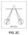
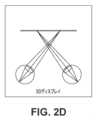
図2Aおよび図2Bは、実世界のオブジェクトを見ているときの焦点距離および眼の輻輳角を示しており、図2Cおよび図2Dは、自動立体視3Dディスプレイを見ているときの焦点距離および眼の輻輳角を描いている。人が実世界において見るもののある部分は、ぼやけることがあり、ディスプレイのケースにおいては、すべての部分が、焦点が合っている。Figures 2A and 2B show focal length and eye convergence angle when viewing a real world object, while Figures 2C and 2D depict focal length and eye convergence angle when viewing an autostereoscopic 3D display. Some parts of what one sees in the real world may be blurred, in the case of a display, all parts are in focus.
図3A~図3Cは、瞳孔に向かって向けられたライトフィールドの遮蔽の様々なレベルを示す。LFシステムは、空間領域だけを制御することができる、従来の立体視3Dディスプレイと異なり、空間領域と角度領域の両方において光放射を制御することを目標とする。ライトフィールドを生成するための異なる方法が、存在する。Figures 3A-3C show various levels of occlusion of the light field directed towards the pupil. Unlike traditional stereoscopic 3D displays, which can only control the spatial domain, LF systems aim to control the light emission in both the spatial and angular domains. Different methods exist for generating the light field.
第1の手法においては、視差が、視聴者の各眼の各所で生成され、見られているオブジェクトの3Dロケーションに対応する正確な網膜ぼけを生成する。一実施形態においては、これは、単一の眼あたり複数のビューを提示することによって行われる。図3A~図3Cは、瞳孔の各所における視差によって引き起こされる遮蔽を示す。結果の様々な映像は、正確な網膜ぼけを生成するために提示することができる、様々なビューを表す。ビューポイントが僅かに異なる少なくとも2つの映像からの光が、同時に眼の瞳孔に入った場合、はるかに現実的な視覚体験が生じる。このケースにおいては、脳が、運動に起因する映像変化を無意識に予測するので、運動視差効果は、自然な状態により良く似る。SMV条件は、正確な視聴距離にある2つのビューの間の間隔を、眼の瞳孔のサイズよりも小さい値まで低減させることによって満たすことができる。In the first approach, parallax is generated at each eye of the viewer to generate a precise retinal blur corresponding to the 3D location of the viewed object. In one embodiment, this is done by presenting multiple views per single eye. Figures 3A-3C show the occlusion caused by parallax at each pupil. The resulting different images represent the different views that can be presented to generate a precise retinal blur. A much more realistic visual experience occurs when light from at least two images with slightly different viewpoints enters the pupil of an eye at the same time. In this case, the motion parallax effect resembles the natural situation more closely, since the brain unconsciously predicts the image changes due to motion. The SMV condition can be met by reducing the separation between two views at the correct viewing distance to a value smaller than the size of the eye's pupil.
第2の手法は、多焦点面手法であり、オブジェクトの映像が、それの3Dロケーションに対応する焦平面に投影される。The second approach is the multi-focal plane approach, where the image of an object is projected onto a focal plane that corresponds to its 3D location.
例示的なマイクロミラー技術。現在のデジタルプロジェクタシステムにおいて一般に使用される、1つの空間光変調器(SLM)コンポーネントは、デジタルマイクロミラーデバイス(DMD)であり、それは、個別にアドレス指定することができ、映像生成においてピクセルの役割を果たすことができる非常に小さいマイクロミラーのアレイを含む。コンポーネントが、方向付けられた光源を用いて照明されたとき、ミラーのうちのいくつかは、投影レンズに向かって傾けられ、スクリーン上に映像を形成し、いくつかは、余分な光を吸収する光トラップに向かって傾けられる。DMDコンポーネントを3D映像投影システムにとって適切なものにする1つの特徴は、達成することができる非常に高速なフレームレートである。DMDとRGB LEDベースの光エンジンとを含むシステムを用いて投影される、フルカラー映像の可能なフレームレートについての1つの例示的な計算が、非特許文献1において実行された。DMDのミラーが、15μsで切り換わることができると仮定すると(=67000バイナリフレーム毎秒)、3つ(RGB)のカラーLEDの強度が、8つの異なるレベル(1、2、4、8、16、32、64、128、256)の間で非常に高速に切り換えられる場合、フルカラー映像は、理論的には、約2800Hz(=67000バイナリフレーム毎秒/8つの(8ビットエンコードされた)強度レベル/3つのカラーチャネル)で投影することができる。1つの例示的なコンポーネントは、バイナリフレームレートが32552Hzほどの高さの、Texas Instruments DLP7000である。このコンポーネントについて、先の計算を行った場合、フルカラー映像については、1360Hzのフレームレートが獲得される。いくつかのDMDコンポーネントに基づいた、1つの例示的な3D映像投影システムが、非特許文献2に提示されている。Exemplary Micromirror Technology. One spatial light modulator (SLM) component commonly used in current digital projector systems is the Digital Micromirror Device (DMD), which contains an array of very small micromirrors that can be individually addressed and play the role of pixels in image generation. When the component is illuminated with a directed light source, some of the mirrors are tilted toward the projection lens to form an image on the screen, and some are tilted toward light traps that absorb excess light. One feature that makes the DMD component suitable for 3D image projection systems is the very fast frame rates that can be achieved. One exemplary calculation of the possible frame rates of a full-color image projected with a system including a DMD and an RGB LED-based light engine was performed in "3D Image Projection Systems: A Practical Guide to 3D Image Projection Systems," 2009. Assuming that the mirrors of the DMD can be switched in 15 μs (=67000 binary frames per second), if the intensities of the three (RGB) color LEDs are switched very quickly between eight different levels (1, 2, 4, 8, 16, 32, 64, 128, 256), a full-color image can theoretically be projected at about 2800 Hz (=67000 binary frames per second/8 (8-bit encoded) intensity levels/3 color channels). One exemplary component is the Texas Instruments DLP7000, with a binary frame rate as high as 32552 Hz. If the above calculations are performed for this component, a frame rate of 1360 Hz is obtained for the full-color image. One exemplary 3D image projection system based on several DMD components is presented in
多くのDMDデバイスは、角度範囲にわたる光のスムーズなスキャニングのために設計されておらず、むしろ、バイナリ(オン-オフ)デバイスとして設計されている。しかしながら、特にこの目的のために開発された、他のタイプのマイクロミラーデバイスも、存在する。そのようなシステムは、例えば、非特許文献3、および非特許文献4において説明されている。これらの資料は、2つの方向において近似的に±30°の角度範囲をスキャンするために使用することができる、マイクロミラーアレイ(MMA)構造について説明している。非特許文献3において言及されている個別にアドレス指定可能なマイクロミラーは、1.5mmの長方形の開口サイズを有し、非特許文献4のミラーは、0.5mm幅であった。両方のシステムは、電流を用いて加熱されたときに、それらの形状を変化させる、バイモルフアクチュエータに基づいていた。電熱バイモルフアクチュエータは、相対的に速い応答時間、低い電力消費を有し、それらは低い電圧(<5V)を用いて駆動することができる。ミラー傾け作動のために使用することができる、他のいくつかのタイプのMEMS(微小電気機械システム)システムも、存在する。一例は非特許文献5から見つけることができる。このケースにおいては、マイクロミラーは、単一の結晶シリコンからエッチングによって製造され、カンチレバー型サスペンション構造が、表面マイクロマシニングによって実現された。結果のミラーは、200μm×500μmばかりでなく、100μm×200μmのサイズも有し、それらは、20°ほど傾けることができた。概して、報告されたスキャニングMMA設計は、ミラーサイズに応じて、最大で数kHzの周波数に達することができる。より小さいミラー開口を用いるほど、デバイスの共振周波数はより高くなり、光の非常に高速な角スキャニングのために使用することができる。Many DMD devices are not designed for smooth scanning of light over an angular range, but rather as binary (on-off) devices. However, there are also other types of micromirror devices developed specifically for this purpose. Such systems are described, for example, in "Micromirror Arrays (MMA)" (2003) and "Micromirror Arrays (MMA)" (2003). These documents describe micromirror array (MMA) structures that can be used to scan an angular range of approximately ±30° in two directions. The individually addressable micromirrors mentioned in "Micromirrors" had a rectangular aperture size of 1.5 mm, while the mirrors in "Micromirrors" were 0.5 mm wide. Both systems were based on bimorph actuators, which change their shape when heated with an electric current. Electrothermal bimorph actuators have a relatively fast response time, low power consumption, and they can be driven using low voltages (<5V). There are also several other types of MEMS (Microelectromechanical Systems) systems that can be used for mirror tilt actuation. An example can be found in "Micromirror Arrays (MMA)" (2003). In this case, the micromirrors were fabricated by etching from single crystal silicon, and the cantilever-type suspension structure was realized by surface micromachining. The resulting mirrors had sizes of 200 μm×500 μm, as well as 100 μm×200 μm, and they could be tilted by as much as 20°. In general, the reported scanning MMA designs can reach frequencies up to several kHz, depending on the mirror size. With smaller mirror apertures, the resonant frequency of the device becomes higher and can be used for very fast angular scanning of light.
例示的な光源技術。例示的な実施形態において使用することができる1つのディスプレイ技術は、非特許文献6において説明されているもののような、いわゆるμLEDである。これらは、今日使用されている標準的なLEDと同じ基本技法を用い、同じ材料から製造される、LEDチップである。しかしながら、μLEDは、一般に利用可能なコンポーネントの小型バージョンであり、それらは、1μm~10μmほどのサイズに小さく作成することができる。非特許文献7は、3μmのピッチで組み立てられた、2μm×2μmチップを含むマトリックスについて説明している。OLEDと比較したとき、μLEDは、はるかに安定的なコンポーネントであり、それらは、非常に高い光強度に達することができる。Exemplary Light Source Technology. One display technology that can be used in the exemplary embodiments are so-called μLEDs, such as those described in [6]. These are LED chips, which use the same basic techniques and are manufactured from the same materials as standard LEDs used today. However, μLEDs are miniaturized versions of commonly available components, and they can be made as small as 1 μm to 10 μm in size. [7] describes a matrix containing 2 μm x 2 μm chips assembled with a pitch of 3 μm. When compared to OLEDs, μLEDs are much more stable components, and they can reach very high light intensities.
1つの剥き出しのμLEDチップは、約20~30nmのスペクトル幅を有する特定の色を放射することができる。白色源は、青色またはUV LEDによって放射された光を、より広い白色光放射スペクトルに変換する蛍光体のレイヤで、チップをコーティングすることによって生み出すことができる。別々の赤色、緑色、および青色LEDチップを隣合せて配置することによって、フルカラー源も生成することができるが、それは、これら3つの原色の組み合わせは、別々の色放射が人の視覚系によって合成されたとき、フルカラーピクセルの感覚を生み出すからである。先に言及した非常に密なマトリックスは、10μm未満の全幅(3×3μmピッチ)を有する、自己発光フルカラーピクセルの製造を可能にする。A single bare μLED chip can emit a specific color with a spectral width of about 20-30 nm. A white source can be created by coating the chip with a layer of phosphor that converts the light emitted by the blue or UV LED into a broader white light emission spectrum. A full-color source can also be created by placing separate red, green, and blue LED chips next to each other, since the combination of these three primary colors creates the sensation of a full-color pixel when the separate color emissions are synthesized by the human visual system. The very dense matrix mentioned earlier allows the fabrication of self-emitting full-color pixels with a total width of less than 10 μm (3×3 μm pitch).
半導体チップからの光抽出効率は、LED構造の電気を光にする効率を決定するパラメータのうちの1つである。抽出効率を高めるために使用することができ、したがって、利用可能な電気エネルギーをより効率的に使用するLEDベースの光源を作り上げることを可能にすることができる、いくつかの方法が存在し、それは、限られた電力供給を有するモバイルデバイスにとって有益である。特許文献1において提示されている1つの方法は、LEDチップの上に直接的に統合された、成形されたプラスチック光学要素の使用に基づいている。より低い屈折率差に起因して、プラスチック形状の統合は、チップが空気によって囲まれているケースと比較して、より多くの光をチップ材料から抽出する。プラスチック形状は、また、プラスチックピースからの光抽出を強化し、放射パターンをより指向的にする方法で光を方向付ける。特許文献2において提示されている別の方法は、μLEDチップからの光抽出を強化する。これは、半導体チップの正面ファセットに対してより直角な光放射角に有利であり、光が高屈折率材料から脱出することをより容易にする形に、チップ自体を成形することによって行われる。これらの構造も、チップから放射される光を方向付ける。後者のケースにおいては、抽出効率は、通常のμLEDと比較したときに、2倍良好であると計算され、光が周囲半球に均一に分布させられる、標準的なチップのランバート分布と比較して、かなり多くの光が、30°の放射コーンに放射された。The light extraction efficiency from a semiconductor chip is one of the parameters that determine the electricity-to-light efficiency of an LED structure. There are several methods that can be used to increase the extraction efficiency and thus make it possible to create LED-based light sources that use the available electrical energy more efficiently, which is beneficial for mobile devices with limited power supplies. One method presented in US Pat. No. 6,399,433 is based on the use of molded plastic optical elements integrated directly on top of the LED chip. Due to the lower refractive index difference, the integration of the plastic shape extracts more light from the chip material compared to the case where the chip is surrounded by air. The plastic shape also enhances the light extraction from the plastic piece and directs the light in a way that makes the radiation pattern more directional. Another method presented in US Pat. No. 6,399,433 enhances the light extraction from the μLED chip. This is done by shaping the chip itself in a shape that favors a light emission angle that is more perpendicular to the front facet of the semiconductor chip and makes it easier for the light to escape the high refractive index material. These structures also direct the light emitted from the chip. In the latter case, the extraction efficiency was calculated to be twice as good as that of a regular μLED, and significantly more light was emitted into a 30° emission cone compared to the Lambertian distribution of the standard chip, where the light is uniformly distributed over the surrounding hemisphere.
いくつかの実施形態に従うと、複数の映像を複数の角度方向に投影するライトフィールド映像エンジン(LFIE)に関するシステムおよび方法が、本明細書において説明される。LFIEは、1)ピクセル化された空間光変調器としての役割を果たすデジタルマイクロミラーデバイス(DMD)と、2)角度視野範囲にわたって映像をスキャンする回転ミラーと、3)映像内において可視の光を発生させる光エンジンとを組み合わせて、異なる映像を生成する。スキャニングミラーの回転サイクルよりも速くDMDマトリックスを変調することによって、異なる映像を、異なる視野角に投影することができる。フルカラー映像は、DMDと同期を取って、光エンジンの光出力を変調することによって、生成することができる。いくつかの実施形態においては、単一のLFIEにおいて2つ以上の光エンジンおよびDMDを使用することによって、同時に、1つまたは複数の方向において、2つ以上の映像を投影することができ、それは、深度方向において異なる焦点面への仮想映像の投影を可能にし、3Dコンテンツのための正確な網膜焦点キューを可能にする。According to some embodiments, systems and methods are described herein for a light field image engine (LFIE) that projects multiple images in multiple angular directions. The LFIE combines 1) a digital micromirror device (DMD) that acts as a pixelated spatial light modulator, 2) a rotating mirror that scans the image over an angular field of view, and 3) a light engine that generates visible light within the image to generate different images. By modulating the DMD matrix faster than the rotation cycle of the scanning mirror, different images can be projected at different viewing angles. Full color images can be generated by modulating the light output of the light engine in synchronization with the DMD. In some embodiments, by using two or more light engines and DMDs in a single LFIE, two or more images can be projected simultaneously in one or more directions, which allows for the projection of virtual images to different focal planes in depth and allows for accurate retinal focusing cues for 3D content.
LFIEは、DMDコンポーネントが様々な既存の2D投影システムにおいて現在使用されているのと同様の方式で、様々なゴーグル不要LF 3Dディスプレイシステムにおいて使用することができる、映像生成中核モジュールとしての役割を果たす。LFIEに加えて、LF投影デバイスは、少なくとも投影レンズを含むモジュールを有する。このレンズは、LFIEによって生成された映像を、視聴者に可視のコンポーネントであるスクリーンに投影する。LF投影システム全体の他のモジュールをしかるべく選択することによって、複数ユーザシナリオまたは単一ユーザシナリオのどちらについても、強化された性能を用いて、同じLFIEを使用することが可能である。The LFIE serves as the image generation core module that can be used in various goggle-free LF 3D display systems in a similar manner as the DMD component is currently used in various existing 2D projection systems. In addition to the LFIE, the LF projection device has a module that includes at least a projection lens. This lens projects the image generated by the LFIE onto a screen, which is the component visible to the viewer. By appropriately selecting the other modules of the overall LF projection system, it is possible to use the same LFIE with enhanced performance for either multi-user or single-user scenarios.
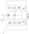
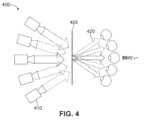
図4は、複数のプロジェクタ410を備えるLF投影システム400の概略的提示を例示しており、図5は、本明細書において説明されるいくつかの実施形態に従った、LFIEを使用するLF投影システム500の概略的提示を例示する。1つの明らかな相違は、使用されるハードウェアの量である。いくつかの投影システム(図4)は、異なるビュー420のために必要とされる映像を(スクリーン405にわたって)生成する、別々の2Dプロジェクタデバイス410の大きいアレイを使用する。これらのデバイスの各々は、自らの空間光変調器(SLM)、制御エレクトロニクス、投影光学素子などを使用する。Figure 4 illustrates a schematic representation of an
いくつかの実施形態に従うと、LFIEに基づいたシステム(図5)は、ただ1つのプロジェクタデバイス510と、投影光学素子520の1つのセットとを有する。回転ミラー515は、プロジェクタデバイス510を用いて生成された映像をスキャンするので、仮想プロジェクタ525のアレイが、ミラー515の平面の後ろに「生成」される。プロジェクタデバイス510は、DMDコンポーネントを含むことができ、DMDコンポーネントは、十分に高速なSLMとしての役割を果たすことができるので、それは、プロジェクタデバイスのアレイ全体(例えば、図4におけるプロジェクタ410のアレイ)に取って代わることができる。そのため、スクリーン505にわたって、単一のプロジェクタデバイス510および単一の投影光学素子520を用いて、複数のビュー525を生成することができる。言い換えると、LFIEベースのシステムは、いくつかの実施形態に従うと、空間多重化の代わりに、時間多重化をより利用することができ、そのような構成を用いて、それから生じる小さいサイズおよび相対的に低いコストを達成する。そのようなシステムのための方法は、高い光強度に耐えることができ、時間多重化を強調する手法にとって十分に高速な、他の小規模のSLMにも拡張することができる。According to some embodiments, an LFIE-based system (FIG. 5) has only one
いくつかの実施形態に従うと、以下でより詳細に説明されるように、LFIEに基づいたシステムは、複数のDMDコンポーネントを利用できる(図14および関連する説明を参照)。例えば、いくつかの実施形態に従うと、図5の回転ミラー515は、図14に示されるように、第2のDMDコンポーネントを用いて置き換えることができる。According to some embodiments, as described in more detail below, an LFIE-based system can utilize multiple DMD components (see FIG. 14 and related discussion). For example, according to some embodiments, the
本明細書において説明される様々な実施形態において、LFIEは、時間多重化と空間多重化の組み合わせを使用することができる。高品質のライトフィールド3D映像の生成は、3D視覚コンテンツの知覚を形成するサブ映像の密な場の生成において、重い多重化を要求する。LFIEにおいては、空間多重化は、高ピクセル数の映像を速やかに変調する、DMDコンポーネントを用いて行われる。時間多重化は、映像を角度空間内に順次的にスキャンする、回転ミラーによって実現される。例えば、異なるカラーコンポーネントのオンとオフを順次的に切り換えることによる、カラー映像の生成においては、LED/レーザダイオードコンポーネントのきわめて高速な切り換えスピードが、使用される。したがって、本明細書において開示されるいくつかの方法は、これらの多重化スキームの両方を最大限利用して、開示されるLFIEシステム/デバイスの効率を高める。In various embodiments described herein, the LFIE can use a combination of temporal and spatial multiplexing. The generation of high quality light field 3D images requires heavy multiplexing in the generation of a dense field of sub-images that form the perception of 3D visual content. In the LFIE, spatial multiplexing is performed using a DMD component that rapidly modulates a high pixel count image. Temporal multiplexing is achieved by a rotating mirror that sequentially scans the image in angular space. For example, in the generation of color images by sequentially switching different color components on and off, the extremely fast switching speed of LED/laser diode components is used. Thus, some methods disclosed herein take full advantage of both of these multiplexing schemes to increase the efficiency of the disclosed LFIE system/device.
いくつかの実施形態に従うと、これらの光学的機能(映像変調、光の発生、および異なる視聴方向における投影)は、3つの別々の光学コンポーネントに分割することができる。これは、機能の最適化を別々に可能にすることができ、それは、各タスクのために別々にコンポーネントを選択し、最適化することができるからである。LFIEを用いるシステムは、したがって、異なる使用事例について最適化することができ、本明細書において説明される手法を非常に多用途にする。According to some embodiments, these optical functions (image modulation, light generation, and projection in different viewing directions) can be split into three separate optical components. This can allow optimization of the functions separately, since components can be selected and optimized separately for each task. A system using LFIE can therefore be optimized for different use cases, making the techniques described herein very versatile.
いくつかの実施形態に従うと、LFIEのすべての説明されたコンポーネントを含むモジュールは、小さいパッケージ内に組み込むことができ、映像エンジンを様々な種類のデバイスと統合することを可能にする。According to some embodiments, a module containing all the described components of the LFIE can be assembled into a small package, allowing the video engine to be integrated into a wide variety of devices.
本明細書において説明されるいくつかの実施形態に従うと、複数の映像を複数の角度方向に投影することが可能なLFIEのためのシステムおよび方法が、存在する。LFIEは、複数の方向から見ることができる3Dシーンのためのライトフィールドを効果的に生成する。各視聴者は、同じ3Dコンテンツの自分自身の立体視ビューを有することができ、3次元映像の知覚が、生じることができる。視聴者が、投影スクリーンの周りを移動するにつれ、各新しい視野角のために映像を変化させることができる。LF投影システム全体の他のモジュールを適切に選択することにより、複数人のユーザまたは1人のユーザのどちらについても、強化された性能を用いて同じLFIEを使用することが可能である。According to some embodiments described herein, there are systems and methods for an LFIE capable of projecting multiple images in multiple angular directions. The LFIE effectively creates a light field for a 3D scene that can be viewed from multiple directions. Each viewer can have their own stereoscopic view of the same 3D content, and a perception of three-dimensional images can result. As the viewer moves around the projection screen, the images can change for each new viewing angle. By appropriately selecting other modules in the overall LF projection system, it is possible to use the same LFIE with enhanced performance for either multiple users or a single user.
いくつかの実施形態に従うと、LFIEは、ピクセル化された空間光変調器としての役割を果たすDMDと、角度視野範囲にわたって映像をスキャンする回転ミラーと、映像内において可視の光を発生させる光エンジンとを組み合わせて、異なる映像を生成する。スキャニングミラーの回転サイクルよりも速くDMDマトリックスを変調することによって、複数の異なる映像を、異なる視野角に投影できる。フルカラー映像は、DMDと同期を取って、光エンジンの光出力を変調することによって、生成することができる。According to some embodiments, the LFIE combines a DMD acting as a pixelated spatial light modulator, a rotating mirror that scans the image over a range of angular fields of view, and a light engine that generates visible light within the image to generate different images. By modulating the DMD matrix faster than the rotation cycle of the scanning mirror, multiple different images can be projected at different viewing angles. Full color images can be generated by modulating the light output of the light engine in synchronization with the DMD.
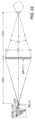
図6は、例示的なLFIE600の構造の概略的な提示を例示する。光エンジン605は、光源607(例えば、RGB LEDまたはレーザダイオード)と、照明光学素子とを含むことができ、DMDコンポーネント610に向けられた光のビームを生成することができる。DMD610において映像ピクセルの役割を果たす小型ミラーは、特定のビュー方向の映像コンテンツに応じて、光を回転ミラー620または光トラップ615のどちらかに反射する。回転ミラー620は、ミラー回転角に依存する角度範囲にわたってスイープしながら、異なる角度方向内に映像を反射する。回転ミラー620は、例えば、往復運動を行うガルバノメトリック型デバイス、または1つの方向に連続的に回転するポリゴンミラー、または他のコンポーネントであることができる。図6の実施形態においては、ミラー620は、第1の位置625にあって、映像を第1の方向627に投影することができ、第2の位置630においては、映像を第2の方向632に投影することができる。6 illustrates a schematic presentation of the structure of an
光エンジン605は、LEDまたはレーザダイオードなど、赤色、緑色、および青色の光を放射する別々のコンポーネントからの出力を合成することによって、フルカラー映像をサポートすることができる。異なる色の出力は、DMD610に同期させることができ、光エンジン605の出力を変調することによって、例えば、コンポーネントのオンとオフを電気的に切り換えることによって、または高速の機械的シャッタを使用することによって、別々の色付きのサブ映像を、高速に連続して表示することができる。光放射コンポーネントの切り換え時間は、例えば、ビューの数およびスキャニングミラーの角回転スピードに関して設定される映像エンジン目標値から、計算することができる。いくつかの実施形態においては、白色光照明源を用い、異なる色は、光エンジン605において、例えば、カラーホイールを用いて、生み出すことができる。そのようなケースにおいては、色付きの出力は、十分に高い精度で、DMD610および回転ミラー620に同期させることができ、設計フェーズ中に、異なるカラーディザリング方法を検討することができる。いくつかの実施形態は、特許文献3において開示されているような、DMDコンポーネントのために開発された、スパイラルカラーホイール設計を利用することができる。The
回転ミラー620は、連続する赤色、緑色、および青色のサブ映像の間で、投影角を変化させるので、角度偏移が、投影されたライトフィールドに導入される。投影デバイス/システム全体の投影レンズまたはスクリーンにおいて、適切な光学要素を使用することによって、色付きのサブ映像を合成して、フルカラー映像を形成することができる。そのような要素は、例えば、プリズム効果、色収差、または回折に基づくことができ、それらは、異なる色付きの光ビームの伝搬方向を選択的に制御するための一般に使用される光学ツールである。The
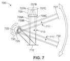
LFIEだけを用いてすべての色付きのサブ映像を同じ方向に投影するための1つの可能な方法は、LFIEを用いたカラー映像生成の概略的な提示を示す、図7に例示されるような光学構成を使用することである。光放射要素707a、707b、707c(例えば、赤色、緑色、および青色LED)が、光エンジン705内に隣合せて位置付けられ、共通の光学素子を用いてDMD710に投影される場合、空間分離711は、照明方向の間の角度分離713に変換することができる。異なる色の照明ビーム709a、709b、709cのタイミングをミラー720の回転に同期させることによって、これらの角度差を使用することができる。異なるLED位置によって引き起こされる小さい角度差は、異なる色の投影の間の時間間隔中における回転ミラー720の動きによって引き起こされる、投影されるサブ映像における小さい角度差をもたらす。これは、LED(または他の光放射要素707)が、ミラー720の回転スピードおよび方向に合わせて、正確な順序でアクティブ化されることを必要とする。光エンジン705からの異なる色付きの照明ビーム709a、709b、709cの間の角度スプレッド713は、投影方向における小さい空間偏移711に変換されるが、3つの色付きのサブ映像が同じ方向に投影される重なり合う空間エリアが、存在し、フルカラーの合成映像をもたらす。概して、LFIEから出力された色付きのサブ映像の間に角度偏移を有する方がよいか、それとも空間偏移を有する方がよいかは、投影デバイス/システム全体の設計、およびカラーラスタリング/ディザリング方法に依存する。One possible way to project all colored sub-images in the same direction using only LFIE is to use an optical configuration as illustrated in FIG. 7, which shows a schematic presentation of color image generation using LFIE. If light-emitting elements 707a, 707b, 707c (e.g. red, green, and blue LEDs) are positioned next to each other in the
図7の実施形態においては、ミラー720は、各ビーム709a、709b、709cに対して第1の位置725にあって、各ビームについてのサブ映像を第1の方向727に投影することができ、各ビーム709a、709b、709cに対する第2の位置730においては、各ビームについてのサブ映像を第2の方向732に投影することができる。In the embodiment of FIG. 7, the
光エンジンの照明出力は、様々な使用事例の意図されたライティング条件に適するように選択される。DMDコンポーネントは、非常に高い光強度に耐えることができるので、光エンジンの最大パワーレベルは、特定の使用事例に最適化することができる。周囲ライティングレベルが高い場合、および/またはより多数のビューが必要とされる場合、より高パワーのコンポーネントを使用することができる。1人または複数人の視聴者の位置を決定する際に、頭部または視聴者の追跡が使用される場合、ライティングビームの切り換えも、映像が適切な方向だけに投影され、潜在的にエネルギーを節約するような方法で、ミラー回転に同期させることができる。このケースにおいては、回転ミラーおよびDMDコンポーネントは、同じ動きを継続することができ、エネルギー節約特徴の制御は、光エンジンを、それからの光がユーザに向かって投影されないときに、オフに切り換えることによって、実行することができる。The illumination output of the light engine is selected to suit the intended lighting conditions of various use cases. Since the DMD components can withstand very high light intensities, the maximum power level of the light engine can be optimized for a particular use case. If the ambient lighting levels are high and/or a larger number of views are required, higher power components can be used. If head or viewer tracking is used in determining the position of one or more viewers, the switching of the lighting beams can also be synchronized to the mirror rotation in such a way that the image is only projected in the appropriate direction, potentially saving energy. In this case, the rotating mirror and DMD components can continue the same motion and control of the energy saving feature can be performed by switching off the light engine when light from it is not being projected towards the user.
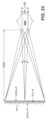
いくつかの実施形態においては、LFIE設計は、水平方向だけにおいて、マルチビューライトフィールドをサポートする。しかしながら、回転ミラーが、水平および垂直の両方向において回転することができるスキャニングミラーで置き換えられた場合、水平および垂直の両方向において固有のビューを有するライトフィールドを形成するように、映像をスキャンすることができる。これは、きわめて高速なスキャニングコンポーネントを利用することがあり、放射される光パワーが非常に多数のビューにわたって拡散されるので、システムに、例えば、光エンジンから必要とされる光強度に、より高い要求を課すことがある。垂直ビューは、それの例示的な実施形態が図8に例示され、ファセットミラーを用いて生成することができ、それは、1つの方向に回転して、DMDによって2つ以上のファセットに反射された映像を投影する。そのようなケースにおいては、単一のDMDは、マトリックスをセクションに分割することによって、ミラーマトリックスの異なる部分において、固有の垂直映像を同時に生成することができる。In some embodiments, the LFIE design supports multi-view light fields in the horizontal direction only. However, if the rotating mirror is replaced with a scanning mirror that can rotate in both horizontal and vertical directions, the image can be scanned to form a light field with unique views in both horizontal and vertical directions. This may utilize extremely fast scanning components and may impose higher demands on the system, for example on the light intensity required from the light engine, since the emitted light power is spread over a large number of views. Vertical views can be generated using a faceted mirror, an exemplary embodiment of which is illustrated in FIG. 8, which rotates in one direction and projects an image reflected by the DMD onto two or more facets. In such cases, a single DMD can simultaneously generate unique vertical images in different parts of the mirror matrix by dividing the matrix into sections.
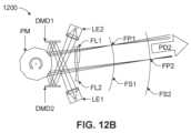
いくつかの実施形態においては、(その実施形態が図12A~図12Bに例示される)1つのLFIEにおいて2つ以上の光エンジンおよびDMDを使用することによって、2つ以上の映像を1つまたはいくつかの方向に同時に投影する。光エンジンによって生成されたビームは、DMDによって変調され、共通の回転ミラーに向けられる。共通のミラーの使用は、正確な同期を保証する。この構造においては、2つ以上の光路が存在し、これらの光チャネルのうちのいくつかまたはすべてに、焦点合わせ光学素子を追加することを可能にする。これは、深度方向において異なる焦点面への仮想映像の投影を可能にし、3Dコンテンツのための正確な網膜焦点キューを可能にする。In some embodiments, two or more light engines and DMDs are used in one LFIE (embodiments of which are illustrated in Figures 12A-12B) to project two or more images simultaneously in one or several directions. The beams generated by the light engines are modulated by the DMD and directed to a common rotating mirror. The use of a common mirror ensures accurate synchronization. In this configuration, there are two or more optical paths, allowing for the addition of focusing optics to some or all of these optical channels. This allows for the projection of virtual images to different focal planes in depth, allowing for accurate retinal focusing cues for 3D content.
いくつかの実施形態に従うと、1つの水平視聴方向にさらされた2つ以上のファセットを有する単一の回転ミラーと一緒に、複数の光エンジンおよびDMDを使用することができ、図8に例示されるように、複数の垂直視聴方向を同時に生成することも可能である。(例えば、上側ファセット806、中間ファセット807、および下側ファセット808を有する)ファセットミラー805が、回転するとき、中間ファセット807は、中間光エンジン(LE2/830)およびDMD(DMD2/835)を用いて生成された映像を、中間水平投影方向(HPD2/845)をスイープしながら、中間の垂直投影方向(VPD2/840)に反射する。類似の光エンジン(LE1/810&LE3/850)およびDMD(DMD1/815&DMD3/855)が、中間ファセット807の上側(806)および下側(808)のファセットから反射される異なる映像を同時に生成したとき、固有のビューを有する他の2つの水平投影平面(例えば、それぞれ、垂直投影方向820、860における水平投影方向)が、中央水平平面(845)の上側(825)および下側(865)に形成される。より多くのファセットをミラーに追加し、また追加の光エンジンおよびDMDモジュールを追加することによって、光エンジンのさらなる時間多重化なしに、垂直方向において複数の視聴位置を生成することも可能である。According to some embodiments, multiple light engines and DMDs can be used in conjunction with a single rotating mirror with two or more facets exposed to one horizontal viewing direction, and multiple vertical viewing directions can be simultaneously generated, as illustrated in FIG. 8. As faceted mirror 805 (e.g., with upper facet 806, middle facet 807, and lower facet 808) rotates, middle facet 807 reflects the image generated with the middle light engine (LE2/830) and DMD (DMD2/835) into an intermediate vertical projection direction (VPD2/840) while sweeping through an intermediate horizontal projection direction (HPD2/845). When similar light engines (LE1/810 & LE3/850) and DMDs (DMD1/815 & DMD3/855) simultaneously generate different images reflected from the upper (806) and lower (808) facets of the middle facet 807, two other horizontal projection planes with unique views (e.g., horizontal projection directions at
図9は、(光エンジン905と、回転ミラー920と、DMD910とを備える)LFIE901を含む、ライトフィールドプロジェクタデバイス900の概略的な提示を例示する。LFIE901に加えて、デバイス900は、少なくとも投影レンズ(または他の投影光学素子)945を含む、投影モジュール940を含む。このレンズ945の目的は、DMD910によって生成された映像を、デバイス900またはシステムの可視コンポーネントであるスクリーン950に投影することである。適切なレンズ設計タイプの1つの例は、Fシータレンズであり、それは、等間隔の角度間隔で投影された光ビームから、フラットな像面を提供することができる。投影モジュール940は、中継レンズも利用することができ、それは、異なる方向に進行する映像を組み合わせて、後にスクリーン950に投影するのがより容易な中間仮想ライトフィールド映像にする際に使用される。第1の位置にあるミラー920を用いると、映像を第1の方向927に投影することができ、第2の位置においては、映像を第2の方向932に投影することができる。FIG. 9 illustrates a schematic presentation of a light
いくつかの実施形態においては、LFIEを含むLFプロジェクタデバイスは、表示スクリーンとともに使用される。図10は、一実施形態に従った、(視聴者1090a、1090b、1090c、1090d、1090eに対するシステムの可視部分である)関連付けられたスクリーン1055を伴った、マルチユーザLF投影システム1002の概略的な提示を例示する。LF投影システム1002のミラー1020が回転するので、DMD1010を用いて生成されたLFサブ映像のセットは、異なる角度で、投影システム1002からスクリーン1055に投影される。スクリーン1055は、各サブ映像の伝搬方向の向きを主要な視聴方向に変える、要素1060を有する。この要素1060は、例えば、成形されたプラスチックのフレネルレンズ、またはエンボス加工されたマイクロプリズムを備える箔であることができる。DMD1010のピクセルマトリックス1070を、レンチキュラレンズシート1057の後ろの焦点に集めるために、別個の焦点合わせ要素1062を使用することができる。この焦点合わせ要素1062は、例えば、マイクロレンズの成形されたアレイ、または回折構造を備えるエンボス加工された箔であることができる。焦点合わせは、いくつかの代替的実施形態においては、投影システム1002内部の投影レンズを用いて達成することができ、そのケースにおいては、スクリーン1055内の焦点合わせ要素1062は、必要ではないことがある。スクリーン1055は、結像された仮想ピクセルマトリックス1070を均一化するための光拡散要素1064も含むことができ、それは、角度調整および焦点合わせ要素特徴(例えば、フィルファクタ)に結び付けられたいくつかまたはすべての映像アーチファクト、ならびに異なる投影されるサブ映像間の小さい不連続を隠すことができる。特定の使用事例に対して、水平ビューだけが望ましい場合、スクリーン光操作要素1057、1060、1062、1064、1070のうちのいくつかは、一方向性(例えば、溝)であることができ、それは、より低いコストをもたらすことができるが、水平および垂直ビューの両方が生成される場合、それらの要素のうちの1つまたは複数は、2次元であることができる。いくつかの実施形態においては、異なるスクリーン要素のすべての必要な光学的機能は、1つのホログラフィック/回折シートに組み込むことができ、それは、柔軟であることさえでき、したがって、現在の既存の通常の2Dプロジェクタ(例えば、ホームシネマ)に類似した、ライトフィールドプロジェクタ1002のための使用事例を可能にする。In some embodiments, the LF projector device including the LFIE is used in conjunction with a display screen. FIG. 10 illustrates a schematic presentation of a multi-user
視聴者に可視のスクリーン1055の前面部分、例えば、レンチキュラレンズシート1057は、既存のマルチビュー自動立体視システムにおいて使用されるレンチキュラレンズ構造と類似した方式で、機能することができる。レンチキュラレンズシート1057の後ろのピクセル行(またはマトリックス)1070の映像は、標準的なマルチビューディスプレイにおいて、LCDディスプレイピクセルのセットが、LFサブピクセルとしてどのように機能するかに類似して、ライトフィールドピクセル(LFP)としての役割を果たすことができる。レンチキュラレンズ1057が、視聴者の前方の視聴空間に仮想ピクセルを投影するとき、異なる投影方向(PD)(またはビュー方向)が、生成される。例えば、図10においては、ピクセルP1は、回転ミラー1020が位置MP1にある一時点において、システム1000を通して、LFP1に結像され、次に、仮想サブピクセルが、スクリーン1055の前方に特定の角度で位置付けられた視聴者1090Aだけに可視の投影方向PD1に投影される。別の時点においては、回転ミラー1020は、位置MP2に移動しており、同じピクセルは、LFP2に結像され、そこから、異なる空間位置および後の時点ではあるが、やはり同じ視聴者1090Aに可視の同じ投影方向PD1に投影される。同様な方法で、ピクセルP5は、2つの異なる時点において、最初はLFP1に、次にLFP2に結像され、次に視聴者1090Eだけに可視であるPD5に投影される。The front portion of the
現在のマルチビューシステムにおいては、サブピクセルの数、およびそれとともに投影方向の数は、ディスプレイ(例えば、LCDパネル)において利用可能なピクセルの数に固定され、ピクセルの数によって制限される。LFIEに基づいたプロジェクタシステムにおいては、本明細書において開示されるように、角度スイープおよびDMDの高速変調ミラーマトリックスが、レンチキュラ構造の後ろに、より密な「仮想」ディスプレイを生成することができる。それは、多用途でもあり、それは、すべてが特定の使用事例に結び付けられる、スクリーンサイズ、ユーザの数、明るさレベルなどの異なる要件に対して、ライトフィールドシステムの空間解像度および角解像度を最適化することができるような、数々の異なる方法で、時間多重化(すなわち、回転ミラーの角度スイープ)および空間多重化(すなわち、DMDピクセルの変調)を組み合わせることができるからである。例えば、3Dライトフィールド映像を、スクリーンから1mの距離に座っている1人のユーザに示すために、または大きい投影キャンバス(もしくはスクリーン)から5mの距離に立っている人々のグループに示すために、同じプロジェクタデバイスを使用することができる。これら2つの使用事例の間の変化は、異なるサイズのスクリーンの選択であること、また特定のスクリーンサイズ、解像度目標などのためのおそらくは(いくらか)異なるレンダリング設定であることができる。In current multi-view systems, the number of sub-pixels, and therefore the number of projection directions, is fixed and limited by the number of pixels available in the display (e.g., LCD panel). In a projector system based on LFIE, the angular sweep and fast modulating mirror matrix of the DMD can generate a denser "virtual" display behind the lenticular structure, as disclosed herein. It is also versatile, since it is possible to combine temporal multiplexing (i.e., angular sweep of the rotating mirror) and spatial multiplexing (i.e., modulation of the DMD pixels) in a number of different ways, which allows the spatial and angular resolution of the light field system to be optimized for different requirements such as screen size, number of users, brightness level, etc., all tied to a specific use case. For example, the same projector device can be used to show a 3D light field image to a single user sitting at a distance of 1 m from the screen, or to a group of people standing at a distance of 5 m from a large projection canvas (or screen). The variation between these two use cases could be the choice of a different size screen, and perhaps (somewhat) different rendering settings for the specific screen size, resolution target, etc.
3Dシーンレンダリング構成は、与えられた使用事例およびハードウェアのための選択されたパラメータに応じて変化することができる。例えば、マイクロミラーマトリックス全体を、スクリーン上の1つのライトフィールドピクセル上に結像させることができ、DMDコンポーネント内に存在するピクセルと同数の個々のビューを生成することが可能である。そのようなケースにおいては、回転ミラーが、それの経路にわたってスイープするにつれて、各LFPが、次から次へと生成され、各々は、多数のビューを有する。DMDマトリックスが、同時にいくつかのLFPの後ろに結像される場合、LFP空間解像度をより高くすることができるが、より少数の固有のビューのコストを伴う。これらのトレードオフのうちのいくつかは、いくつかの実施形態においては、光学的機能が異なるコンポーネントに分割されていることに起因して、ハードウェアを変更する必要なしに、レンダリング設定を変更することによって行うことができる。回転ミラーが、それの経路をスイープするにつれて、DMDも、異なるレートで変調することができ、レンチキュラシートの後ろの仮想ディスプレイ内にエリアをインターレースまたはオーバラップすることを可能にする。特許文献4において説明されるように、例えば、映像の明るさおよび/またはパワー消費を改善するために、コンテキスト適応型レンダリング方法を使用することができる。さらに、また、超解像度アルゴリズムをレンダリングスキームに適用して、さもなければ、DMDマトリックスおよび結像システムの特性によって制限される、空間解像度を高めることができる。The 3D scene rendering configuration can vary depending on the parameters selected for a given use case and hardware. For example, the entire micromirror matrix can be imaged onto one light field pixel on the screen, generating as many individual views as there are pixels in the DMD component. In such a case, as the rotating mirror sweeps across its path, each LFP is generated one after the other, each with multiple views. If the DMD matrix is imaged behind several LFPs at the same time, the LFP spatial resolution can be higher, but at the cost of fewer unique views. Some of these tradeoffs can be made in some embodiments by changing the rendering settings without having to change the hardware due to the optical functions being split into different components. As the rotating mirror sweeps across its path, the DMD can also be modulated at different rates, allowing interlacing or overlapping areas in the virtual display behind the lenticular sheet. As described in US Pat. No. 6,233,999, context-adaptive rendering methods can be used, for example, to improve image brightness and/or power consumption. Additionally, super-resolution algorithms can also be applied to the rendering scheme to enhance spatial resolution that would otherwise be limited by the properties of the DMD matrix and imaging system.
視聴者から見て、LFIEおよび投影光学素子は、透過させる映像の場合はスクリーンの後方に、または反射させる映像の場合はスクリーンの前方に位置付けることができる。後方照明スクリーンは、それのコンポーネントを1つのパッケージ内に有する「投影TV」に似たデバイスを生み出すことができ、一方、前方照明スクリーンは、ホームシアタシステムにおけるディスプレイ構成により近い製品をもたらすことができる。スクリーンは、3D映像をより大きいまたはより小さい角度から見ることを可能にするために、LFIEによって生成されたライトフィールドの角度範囲を拡大または縮小することもできる。そのようなスクリーンは、例えば、異なる焦点長を有する2つ(またはより多く)のマイクロレンズまたは小型レンズのコンポーネントから構成することができる。そのような設計においては、構造は、(特許文献4において説明されているように)それらの間の距離がそれらの焦点長の和に等しくなるような方法で、取り付けられる。From the viewer's perspective, the LFIE and projection optics can be positioned behind the screen for transmitted images, or in front of the screen for reflected images. A rear-lit screen can produce a device similar to a "projection TV" with its components in one package, while a front-lit screen can result in a product closer to the display configuration in a home theater system. The screen can also expand or reduce the angular range of the light field generated by the LFIE to allow the 3D image to be viewed from larger or smaller angles. Such a screen can be composed of, for example, two (or more) microlens or lenslet components with different focal lengths. In such a design, the structures are mounted in such a way that the distance between them is equal to the sum of their focal lengths (as described in U.S. Pat. No. 6,399,323).
回転ミラーは、角度空間にわたって連続的にスイープするので、非常に密なライトフィールドの生成のために、デバイスを使用することが可能である。3Dシーンの知覚は、一般に、視聴者に向かって投影される少なくとも2つの異なるビューポイント-各眼に対して1つのビュー-を必要とする。DMDデバイスは、高いリフレッシュ周波数を有し、反射される映像は、視聴空間に連続的に投影することができるので、この立体視映像条件は、開示されるシステムおよび方法によって満足される。視聴者が十分に近く、DMDリフレッシュ周波数が適切である場合、2つ以上の映像を1人の視聴者の瞳孔に投影することも可能である。これは、「超多視点」条件を満たし、視聴者により自然な視聴体験を提供することができる。先に説明したように、LFIEは、2つ以上の焦平面の生成のためにも使用することができ、視聴者から異なる深度距離にある仮想映像、およびより自然な網膜焦点キューをもたらす。Because the rotating mirrors sweep continuously through the angular space, it is possible to use the device for the generation of a very dense light field. Perception of a 3D scene generally requires at least two different viewpoints projected towards the viewer - one view for each eye. This stereoscopic imaging condition is met by the disclosed system and method, because DMD devices have a high refresh frequency and the reflected images can be projected continuously into the viewing space. If the viewer is close enough and the DMD refresh frequency is appropriate, it is also possible to project more than one image into one viewer's pupil. This can satisfy the "super multi-view" condition and provide the viewer with a more natural viewing experience. As explained earlier, LFIE can also be used for the generation of more than one focal plane, resulting in virtual images at different depth distances from the viewer and more natural retinal focusing cues.
図11は、LFIEを含むLFプロジェクタデバイスを利用する、ライトフィールド投影システムの概略的な提示を例示する。システム1100は、再生デバイス1105を含むことができ、それは、3DコンテンツをLF投影システム1110に提供し、次に、それが、スクリーン1115に投影されるLF映像を生成する。投影システムは、例えば、スクリーン1115の前方のテーブル上に配置することができる。そのようなスクリーン1115は、適切な支持構造(例えば、壁、スタンドなど)に取り付けることができ、または同じテーブル上もしくは投影システム1110に対して異なる表面上に配置することができる。再生デバイス1105は、ディスプレイ信号1107を計算して、投影システム1110に送信し、それは、回転ミラーのモータをアクティブ化し、ミラーと同期するようにDMDを制御する、制御エレクトロニクスを含む。反射スクリーンは、テーブルの周りの異なる視聴位置から異なるビューを見ることができるように、水平方向において、ライトフィールド角度構造を維持し、拡大し、または縮小する。スクリーンは、異なる高さに位置付けられた眼を有する視聴者に対して、映像をより均一にするために、垂直方向においても反射光を拡散することができる。眼は水平に位置付けられるので、水平方向だけにおいて異なるビューポイントを提供することは、3D映像知覚に適している。11 illustrates a schematic presentation of a light field projection system utilizing an LF projector device including an LFIE. The
以下の図14に関して説明されるような、いくつかの実施形態においては、各ピクセルのオン-オフ状態および角度方向に別々に対処することが可能なLFIEを生み出すために、回転ミラーの代わりに、第2のDMDコンポーネントを使用することができる。そのような構成においては、ピクセルのオンとオフを切り換えるだけの代わりに、第1のDMDデバイスが、より高速なレートで、ピクセルのオンとオフを切り換えるとき、第2のDMDは、角度領域をスムーズな動きでスキャンする。これらの実施形態においては、第2のDMDのより大きいピクセルを照明するために、第1のDMD内の2つ以上のミラーピクセルを使用することができる。第1のコンポーネントのマイクロミラーのうちのいくつかを回折構造などの微小光学特徴でコーティングすることによって、微小光学特徴が、投影システム全体の焦点長を変更したとき、映像を異なる焦平面に投影することができ、したがって、複数の方向および複数の仮想焦平面を有する、真のライトフィールドを生成する。2つのDMDの使用は、これを可能にするが、それは、第1のDMDのピクセルを、第2のDMDのピクセルに別々にマッピングすることができるからである。In some embodiments, such as those described with respect to FIG. 14 below, a second DMD component can be used instead of a rotating mirror to create an LFIE that can address the on-off state and angular direction of each pixel separately. In such a configuration, instead of just switching pixels on and off, the second DMD scans the angular region in a smooth motion as the first DMD device switches pixels on and off at a faster rate. In these embodiments, two or more mirror pixels in the first DMD can be used to illuminate larger pixels of the second DMD. By coating some of the micromirrors of the first component with micro-optical features such as diffractive structures, the images can be projected to different focal planes when the micro-optical features change the focal length of the entire projection system, thus creating a true light field with multiple directions and multiple virtual focal planes. The use of two DMDs makes this possible because the pixels of the first DMD can be mapped separately to the pixels of the second DMD.
いくつかの実施形態においては、例えば、LCDスクリーンへの、非常に密な指向性バックライトの生成において、光エンジンと回転ミラーと(おそらくはDMDと)を備えるLFIEのバリエーションを使用することができる。また、本明細書において説明されるスクリーン設計は、同じ時間/空間多重化スキームが使用される、簡略化されたシステムを補完することができる。In some embodiments, a variation of the LFIE with a light engine and a rotating mirror (possibly with a DMD) can be used to generate very dense directional backlighting, for example for LCD screens. Also, the screen designs described herein can complement simplified systems where the same time/spatial multiplexing schemes are used.
いくつかの実施形態においては、2つの同一のLFIEを使用して、自動立体視3D LFディスプレイ投影システムを達成することができる。2つのLFIEが、互いに約65mmの距離に位置付けられた場合、2つの同時に投影されたライトフィールドは、人の眼の平均的な瞳孔間距離に中心がある2つのアイボックスに適合する。本明細書において説明されるスクリーンが、両方の投影されるアイボックスを複数の方向に反射または屈折させる際に使用される場合、自動立体視ビューのセットが、複数のユーザのために生成される。そのような構成は、生成されるライトフィールドの角度範囲が、小さいアイボックスに制限されるので、水平および垂直の両方向において、より密なライトフィールドを生成することができる。制限された角度空間は、レンダリングおよび制御システムのために、より低いデータレート要件を有することもできる。加えて、ユーザ位置の認識のために、アイトラッキングシステムを使用することができる。In some embodiments, two identical LFIEs can be used to achieve an autostereoscopic 3D LF display projection system. When the two LFIEs are positioned at a distance of about 65 mm from each other, the two simultaneously projected light fields fit into two eyeboxes centered at the average interpupillary distance of the human eye. When the screen described herein is used to reflect or refract both projected eyeboxes in multiple directions, a set of autostereoscopic views is generated for multiple users. Such a configuration can generate denser light fields in both horizontal and vertical directions, since the angular range of the generated light fields is limited to a small eyebox. The limited angular space can also have lower data rate requirements for the rendering and control systems. In addition, an eye tracking system can be used for recognition of the user position.
例示的なLFIE装置の1つの可能な構造が、図12A~図12Bに示されている。例示的なLFIEは、2つの別々の光エンジン(LE1、LE2)と、デジタルマイクロミラーデバイス(DMD1、DMD2)と、焦点レンズ(FL1、FL2)とを有し、それらは、デバイス1200を通る2つの異なる光路または映像チャネルを形成する。LEによって生成された2つの照明光ビームは、最初にDMDに向けられ、それは、映像変調を実行し、ビームを単一のポリゴンミラー(PM)の2つの異なるファセットに反射する。映像ビームは、PMファセットから反射され、図12A~図12Bにおいては異なる(しかし必ずしもそうである必要はない)FLを通して2つの映像チャネルに対して向けられ、同じ投影方向(PD1、PD2)において、異なる焦点面(FS1、FS2)を有する2つの異なる映像の同時投影を可能にする。PMが回転するにつれて、照明されたファセットと映像ビームとの間の角度は、図12Aに示されるような第1の回転位置から、図12Bに示されるような第2の回転位置に変化する。PMの回転運動が、連続的に投影方向の間を推移させるので、2つの異なる連続的な焦点面(FS1、FS2)が、投影空間を通る2つの光路スイープの焦点(FP1、FP2)として生成される。DMDが、照明されたPMファセットがビーム経路にわたって回転するのにかかる時間よりも高いリフレッシュレートを用いて、投影された映像ビームを変調するとき、複数の固有の視聴方向および2つの焦点面を有する、真の3Dライトフィールド映像が、生成される。One possible structure of an exemplary LFIE device is shown in Figures 12A-12B. The exemplary LFIE has two separate light engines (LE1, LE2), digital micromirror devices (DMD1, DMD2), and focusing lenses (FL1, FL2) that form two different light paths or image channels through the
例示的なLFIEを用いて生成される固有の視聴方向の数は、1つのPMファセットが設計された投影角度範囲にわたってスイープするのにかかる時間内にDMDを用いて行うことができる、映像変調サイクルの数によって決定される。DMDと同期して変調される、赤色、緑色、および青色LEDを使用することによる、3×8ビットフルカラー投影のために、例示的な映像エンジンを使用することができる。上で説明された例示的な計算が、参考として使用される場合、33kHzバイナリフレームレートを有するマイクロミラーコンポーネントについて、約1360Hzのフルカラー映像リフレッシュ周波数を計算することができる。この仕様を満たす1つの既存のコンポーネントは、Texas Instrument DLP7000である。視覚の中心において、またかなり明るい周囲ライティング条件において、フリッカのない映像のために一般に使用されるしきい値は、60Hzである。これら2つの値から、単一のDMDを用いて、約23個の固有のフリッカのないフルカラービューを生成することができると決定することができる。8ビット未満の色深度もしくはモノクロの映像が使用される場合、または2つ以上のDMDが同時に使用され、それらの投影角が異なる場合、ビューの数を増加させることができる。図12A~図12Bに示されるLFIEの例においては、深度方向における第2の焦点面の生成のために、第2のDMDが使用されるが、投影されるビューの数を2倍にして約46個にするためにも、それを使用することができる。The number of unique viewing directions generated with the exemplary LFIE is determined by the number of image modulation cycles that can be performed with the DMD in the time it takes one PM facet to sweep across the designed projection angle range. The exemplary image engine can be used for 3×8-bit full-color projection by using red, green, and blue LEDs modulated synchronously with the DMD. If the exemplary calculations described above are used as a reference, a full-color image refresh frequency of approximately 1360 Hz can be calculated for a micromirror component with a 33 kHz binary frame rate. One existing component that meets this specification is the Texas Instrument DLP7000. The commonly used threshold for flicker-free images at the center of vision and in fairly bright ambient lighting conditions is 60 Hz. From these two values, it can be determined that approximately 23 unique flicker-free full-color views can be generated with a single DMD. The number of views can be increased if less than 8-bit color depth or monochrome images are used, or if two or more DMDs are used simultaneously and their projection angles are different. In the LFIE example shown in Figures 12A-12B, a second DMD is used to generate a second focal plane in the depth direction, but it can also be used to double the number of projected views to approximately 46.
LFIEの投影角が、±10度に設計され、投影光学素子およびスクリーンを備えるシステム全体が、角度スプレッドが2倍になるように設計された場合、2つのビューの間の角度差は、約1.8度である。これは、65mmの通常の瞳孔間距離を有する視聴者が、2m未満の距離から、立体視3D映像を見ることができることを意味する。何人かの異なる視聴者が、彼ら自身の視聴方向から、同じ3Dコンテンツを立体視的に見ることもできる。視聴者は、自然な網膜焦点キューを提供することによって3D効果を強化する2つの異なる焦点面も、深度方向において有する。そのような構成が、図13Aにおいて例示されている。If the projection angle of the LFIE is designed to be ±10 degrees and the whole system including the projection optics and the screen is designed to have a double angular spread, the angular difference between the two views is about 1.8 degrees. This means that a viewer with a normal interpupillary distance of 65 mm can see a stereoscopic 3D image from a distance of less than 2 m. Several different viewers can also see the same 3D content stereoscopically from their own viewing directions. The viewer also has two different focal planes in the depth direction, which enhances the 3D effect by providing natural retinal focal cues. Such a configuration is illustrated in FIG. 13A.
図13Bは、図13Aと同じLFIEに基づくが、1人のユーザ用に設計された、代替システムを例示しており、投影モジュールは、投影されるライトフィールドの角度スプレッドを半分に圧縮して、2つの隣接ビュー間において約0.45度の角度差をもたらす。視聴者が、約0.5mの距離に位置付けられる場合、単一のビューの視聴ゾーンの幅は、約4mmであり、それは、穏当なライティング条件における通常の眼の瞳孔サイズに対応する。これは、2つの異なる映像を、1人の視聴者の瞳孔内に同時に投影することを可能にすることができ、それは、超多視点条件を満たし、特に高速に動く3D映像コンテンツのために、さらに現実的な焦点キューを提供することができる。図13Bのシステムは、フェイストラッキングと一緒に使用することもできる。Figure 13B illustrates an alternative system based on the same LFIE as Figure 13A but designed for a single user, where the projection module compresses the angular spread of the projected light field by half, resulting in an angular difference of about 0.45 degrees between two adjacent views. When the viewer is positioned at a distance of about 0.5 m, the width of the viewing zone of a single view is about 4 mm, which corresponds to the normal eye pupil size in moderate lighting conditions. This can allow two different images to be projected simultaneously within the pupil of a single viewer, which can satisfy the super multi-view requirement and provide even more realistic focus cues, especially for fast-moving 3D video content. The system of Figure 13B can also be used with face tracking.
いくつかの実施形態においては、ライトフィールド映像エンジンを用いて3Dマルチビュー映像を表示する方法であって、光エンジンからの光をデジタルマイクロミラーデバイス(DMD)に出力するステップと、DMDからの出力光の少なくともいくらかを回転ミラーに反射するために、DMDをピクセル化された空間光変調器として動作させるステップと、DMDから反射された光によって表される映像を角度視野範囲にわたってスキャンするために、回転ミラーをサイクルレートで回転させるステップと、回転ミラーのサイクルレートよりも高速なレートで、DMDを変調するステップと、光エンジンからの出力光をDMDと同期させて変調することによって、フルカラー映像を生成するステップとを含む方法が、存在することができる。In some embodiments, there may be a method of displaying a 3D multi-view image using a light field image engine, the method including: outputting light from the light engine to a digital micromirror device (DMD); operating the DMD as a pixelated spatial light modulator to reflect at least some of the output light from the DMD onto a rotating mirror; rotating the rotating mirror at a cyclic rate to scan an image represented by the light reflected from the DMD over an angular field of view range; modulating the DMD at a rate faster than the cyclic rate of the rotating mirror; and generating a full color image by modulating the output light from the light engine in synchronization with the DMD.
いくつかの実施形態においては、3Dマルチビュー映像を表示する方法であって、複数のカラー照明器の同期の取れた時間変調を実行するステップであって、各カラー照明器の出力光は、反射要素のピクセル化された別々に制御可能なマトリックスに入射する、ステップと、反射要素のマトリックスに入射する光の少なくともいくらかを、可動ミラーアセンブリに反射させるステップと、カラー照明器の変調と反射要素の制御可能なマトリックスの両方に同期させられた方式で、ミラーアセンブリを角度にわたってスイープするステップとを含む方法が、存在することができる。方法は、反射要素のマトリックスから反射された光が、可動ミラーアセンブリまたは光トラップのどちらかに入射することを含むことができる。方法は、典型的な人の瞳孔間距離と同じほどの大きさの複数の窓にわたって表示される複数の別々のビューを提供するために、映像コンテンツが、レンダリングされ、時間的に変調された方式でディスプレイデバイスに提示されることを含むことができる。方法は、典型的な人の瞳孔間距離と同じほどの大きさの複数の窓を有するホログラフィックスクリーンに投影される複数の別々のビューを提供するために、映像コンテンツが、レンダリングされ、時間的に変調された方式でディスプレイデバイスに提示されることを含むことができる。In some embodiments, there may be a method of displaying a 3D multi-view video comprising: performing synchronized temporal modulation of a plurality of color illuminators, the output light of each color illuminator being incident on a pixelated, separately controllable matrix of reflective elements; reflecting at least some of the light incident on the matrix of reflective elements to a movable mirror assembly; and sweeping the mirror assembly through an angle in a manner synchronized to both the modulation of the color illuminators and the controllable matrix of reflective elements. The method may include the light reflected from the matrix of reflective elements being incident on either the movable mirror assembly or a light trap. The method may include the video content being rendered and presented on a display device in a temporally modulated manner to provide a plurality of separate views displayed across a plurality of windows as large as a typical human interpupillary distance. The method may include the video content being rendered and presented on a display device in a temporally modulated manner to provide a plurality of separate views projected onto a holographic screen having a plurality of windows as large as a typical human interpupillary distance.
いくつかの実施形態においては、第1および第2の光エンジンと、第1および第2のデジタルマイクロミラーデバイス(DMD)と、回転ミラーと、第1および第2の焦点レンズとを備える、ライトフィールド映像エンジン投影システムを用いて、3Dマルチビュー映像を表示する方法であって、第1のDMDにおいて映像変調を実行し、第1の光エンジンによって生成された第1の光ビームの少なくとも一部を、第1の映像ビームとして、回転ミラーの第1のファセットに反射させるステップであって、第1のファセットは、第1の映像ビームを、第1の焦点レンズを通して、第1の焦点面に反射するように構成される、ステップと、第2のDMDにおいて映像変調を実行し、第2の光エンジンによって生成された第2の光ビームの少なくとも一部を、第2の映像ビームとして、回転ミラーの第2のファセットに反射させるステップであって、第1および第2の映像ビームが、第1の投影方向において、同時に投影されるように、第2のファセットは、第2の映像ビームを、第2の焦点レンズを通して、第1の焦点面とは異なる第2の焦点面に反射するように構成される、ステップと、各映像ビームの焦点が、投影空間にわたってスイープするとき、第1および第2の焦点面が、連続であるように、第1および第2の映像ビームが、少なくとも第2の投影方向において、同時に投影されるように、回転ミラーを回転させるステップと、複数の固有の視聴方向と2つの焦点面とを有する3Dライトフィールド映像が、生成されるように、回転ミラーの回転サイクルレートよりも高いリフレッシュレートで、第1および第2のDMDを変調するステップとを含む方法が、存在することができる。方法は、典型的な人の瞳孔間距離と同じほどの大きさの複数の窓にわたる表示のための複数の別々のビューを提供するため、映像コンテンツが、レンダリングされ、時間的に変調された方式でライトフィールド映像エンジン投影システムによってディスプレイデバイスに提示されることを含むことができる。方法は、典型的な人の瞳孔間距離と同じほどの大きさの複数の窓を有するホログラフィックスクリーンへの投影のための複数の別々のビューを提供するため、映像コンテンツが、レンダリングされ、時間的に変調された方式でライトフィールド映像エンジン投影システムによってディスプレイデバイスに提示されることを含むことができる。方法は、光エンジンとDMDの両方に同期させられた方式で、回転ミラーが角度にわたってスイープすることを含むことができる。方法は、第1のDMDが、反射要素のピクセル化された別々に制御可能なマトリックスを含むことを含むことができる。In some embodiments, a method for displaying a 3D multi-view image using a light field image engine projection system comprising first and second light engines, first and second digital micromirror devices (DMDs), a rotating mirror, and first and second focusing lenses, includes the steps of: performing image modulation on the first DMD and reflecting at least a portion of a first light beam generated by the first light engine as a first image beam onto a first facet of the rotating mirror, the first facet being configured to reflect the first image beam through the first focusing lens to a first focal plane; performing image modulation on the second DMD and reflecting at least a portion of a second light beam generated by the second light engine as a second image beam onto a first facet of the rotating mirror, the first facet being configured to reflect the first image beam through the first focusing lens to a first focal plane; There may be a method including: reflecting a first and second image beam off a second facet, the second facet being configured to reflect the second image beam through a second focusing lens to a second focal plane different from the first focal plane, such that the first and second image beams are simultaneously projected in at least the first projection direction; rotating the rotating mirror such that the first and second image beams are simultaneously projected in at least the second projection direction such that the first and second focal planes are continuous as the focal points of each image beam sweep across the projection space; and modulating the first and second DMDs at a refresh rate higher than the rotation cycle rate of the rotating mirror such that a 3D light field image having multiple unique viewing directions and two focal planes is generated. The method may include the video content being rendered and presented to the display device by the light field image engine projection system in a temporally modulated manner to provide multiple separate views for display across multiple windows as large as a typical human interpupillary distance. The method can include video content being rendered and presented to a display device by a light field image engine projection system in a temporally modulated manner to provide multiple separate views for projection onto a holographic screen having multiple windows as large as a typical human interpupillary distance. The method can include a rotating mirror sweeping through an angle in a manner synchronized with both the light engine and the DMD. The method can include the first DMD including a pixelated, separately controllable matrix of reflective elements.
いくつかの実施形態においては、3Dマルチビュー映像を表示するためのライトフィールド映像エンジン投影システムであって、少なくとも2つの光エンジン、少なくとも2つのデジタルマイクロミラーデバイス(DMD)、および回転ミラーを備えるライトフィールド映像エンジンと、投影光学素子、および角度拡大要素を備える投影モジュールとを備えるライトフィールド映像エンジン投影システムが、存在することができる。方法は、第1のDMDが、映像変調を実行し、第1の光エンジンによって生成された第1の光ビームの少なくとも一部を、第1の映像ビームとして、回転ミラーの第1のファセットに反射するように構成され、第1のファセットが、第1の映像ビームを、第1の焦点レンズを通して、第1の焦点面に反射するように構成されることを含むことができる。方法は、第2のDMDが、映像変調を実行し、第2の光エンジンによって生成された第2の光ビームの少なくとも一部を、第2の映像ビームとして、回転ミラーの第2のファセットに反射するように構成され、第2のファセットが、第2の映像ビームを、第2の焦点レンズを通して、第1の焦点面とは異なる第2の焦点面に反射するように構成されることを含むことができる。方法は、第1および第2の映像ビームが、第1の投影方向において、同時に投影されることを含むことができる。方法は、第1および第2の映像ビームが、第1および第2の焦点面にわたって連続的に投影されるように、ライトフィールド映像エンジンが、回転ミラーを用いて、第1および第2の映像ビームを回転させるように構成されることを含むことができる。方法は、複数の固有の視聴方向と2つの焦点面とを有する3Dライトフィールド映像を生成するために、DMDが、回転ミラーの回転サイクルレートよりも高いリフレッシュレートで、第1および第2の映像ビームを変調するように構成されることを含むことができる。方法は、ライトフィールド映像エンジン投影システムが、再生デバイスから3Dコンテンツを受信し、ライトフィールド映像をスクリーン上に生成するように構成されることを含むことができる。In some embodiments, there may be a light field image engine projection system for displaying 3D multi-view images, the light field image engine comprising at least two light engines, at least two digital micromirror devices (DMDs), and a rotating mirror, and a projection module comprising a projection optics and an angular magnification element. The method may include a first DMD configured to perform image modulation and to reflect at least a portion of a first light beam generated by the first light engine as a first image beam to a first facet of the rotating mirror, the first facet configured to reflect the first image beam through a first focusing lens to a first focal plane. The method may include a second DMD configured to perform image modulation and to reflect at least a portion of a second light beam generated by the second light engine as a second image beam to a second facet of the rotating mirror, the second facet configured to reflect the second image beam through a second focusing lens to a second focal plane different from the first focal plane. The method can include the first and second image beams being projected simultaneously in a first projection direction. The method can include the light field image engine being configured to rotate the first and second image beams with a rotating mirror such that the first and second image beams are projected continuously across first and second focal planes. The method can include the DMD being configured to modulate the first and second image beams at a refresh rate higher than a rotation cycle rate of the rotating mirror to generate a 3D light field image having multiple unique viewing directions and two focal planes. The method can include the light field image engine projection system being configured to receive 3D content from a playback device and generate a light field image on a screen.
いくつかの実施形態においては、第1および第2の光エンジン、第1および第2のデジタルマイクロミラーデバイス(DMD)、回転ミラー、ならびに第1および第2の焦点レンズを備えるライトフィールド映像エンジン投影システムと、プロセッサと、プロセッサ上において実行されたときに、第1のDMDにおいて映像変調を実行し、第1の光エンジンによって生成された第1の光ビームの少なくとも一部を、第1の映像ビームとして、回転ミラーの第1のファセットに反射させるステップであって、第1のファセットは、第1の映像ビームを、第1の焦点レンズを通して、第1の焦点面に反射するように構成される、ステップと、第2のDMDにおいて映像変調を実行し、第2の光エンジンによって生成された第2の光ビームの少なくとも一部を、第2の映像ビームとして、回転ミラーの第2のファセットに反射させるステップであって、第1および第2の映像ビームが、第1の投影方向において、同時に投影されるように、第2のファセットは、第2の映像ビームを、第2の焦点レンズを通して、第1の焦点面とは異なる第2の焦点面に反射するように構成される、ステップと、各映像ビームの焦点が、投影空間にわたってスイープするとき、第1および第2の焦点面が、連続であるように、第1および第2の映像ビームが、少なくとも第2の投影方向において、同時に投影されるように、回転ミラーを回転させるステップと、複数の固有の視聴方向と2つの焦点面とを有する3Dライトフィールド映像が、生成されるように、回転ミラーの回転サイクルレートよりも高いリフレッシュレートで、第1および第2のDMDを変調するステップとを含む機能を実行するように動作する命令を記憶する、非一時的コンピュータ可読記憶媒体とを備えるシステムが、存在することができる。In some embodiments, a light field image engine projection system includes a processor, the processor comprising: a first and second light engine, a first and second digital micromirror device (DMD), a rotating mirror, and a first and second focusing lens; and a processor that, when executed on the processor, performs image modulation on the first DMD and reflects at least a portion of a first light beam generated by the first light engine as a first image beam to a first facet of the rotating mirror, the first facet being configured to reflect the first image beam through the first focusing lens to a first focal plane; and a second DMD that performs image modulation on the second DMD and reflects at least a portion of a second light beam generated by the second light engine as a second image beam to a second facet of the rotating mirror, the second facet being configured to reflect the first image beam through the first focusing lens to a first focal plane. There may be a system comprising a non-transitory computer-readable storage medium storing instructions operable to perform functions including: a second facet configured to reflect the second image beam through a second focusing lens to a second focal plane different from the first focal plane such that the first and second image beams are simultaneously projected in the first projection direction; rotating the rotating mirror such that the first and second focal planes are continuous as the focal points of each image beam sweep across the projection space such that the first and second image beams are simultaneously projected in at least the second projection direction; and modulating the first and second DMDs at a refresh rate higher than the rotation cycle rate of the rotating mirror such that a 3D light field image having multiple unique viewing directions and two focal planes is generated.
本明細書において説明されるいくつかの実施形態に従うと、二重DMDライトフィールド映像エンジンを使用して、投影される3Dライトフィールドを生成するためのシステムおよび方法が、存在する。様々な実施形態が、光学的方法の形態を取る。他の実施形態は、複数の映像をいくつかの角度方向に投影することが可能な、二重DMDライトフィールド映像エンジン(DDMD-LFIE)を含む。DDMD-LFIEは、ピクセル化された空間光変調器としての役割を果たす2つのデジタルマイクロミラーデバイス(DMD)の組み合わせと、映像内において可視の光を生成する光エンジンとを使用して、異なる映像を生成する。DMDは順番に方向付けられ、第2のDMDは、ある範囲にわたってマイクロミラー傾き角をスキャンする。正確なタイミングと組み合わされたこの変調は、いくつかの3Dコンテンツの様々な2Dビューが投影される角/FOVの制御を可能にする。According to some embodiments described herein, there are systems and methods for generating a projected 3D light field using a dual DMD light field imaging engine. Various embodiments take the form of an optical method. Other embodiments include a dual DMD light field imaging engine (DDMD-LFIE) capable of projecting multiple images at several angular orientations. The DDMD-LFIE generates different images using a combination of two digital micromirror devices (DMDs) that act as pixelated spatial light modulators and a light engine that generates visible light in the images. The DMDs are oriented in sequence and the second DMD scans the micromirror tilt angle over a range. This modulation combined with precise timing allows control of the angle/FOV at which various 2D views of some 3D content are projected.
多くの実施形態においては、第1のDMDコンポーネントは、第2のDMDよりも高い解像度および小さいピクセルを有する。第1のDMDはまた、第2のDMDよりも相当高速に変調される。より高速な変調スピードのため、第1のDMDは、第2のDMDの角度スイープの各サイクルの間に、第2のDMD上に何度も結像される。DMDの説明される組み合わせは、2つ以上の映像を単一の視野角に同時に投影するために、使用することができる。この時間多重化は、仮想映像の異なる焦点面への投影を可能にし、3Dコンテンツのための正確な網膜焦点キューを可能にする。各視聴者は、同じ3Dコンテンツの自分自身の立体視ビューを観察し、3D映像の知覚が、生成される。視聴者が、投影スクリーンの周りを移動するにつれて、異なる視野角に対して、観察される映像が変化する。DMDと同期して、光エンジンの光出力を変調することによって、フルカラー映像を生成することができる。In many embodiments, the first DMD component has a higher resolution and smaller pixels than the second DMD. The first DMD is also modulated much faster than the second DMD. Because of the faster modulation speed, the first DMD is imaged onto the second DMD multiple times during each cycle of the second DMD's angular sweep. The described combination of DMDs can be used to project two or more images simultaneously at a single viewing angle. This time multiplexing allows for the projection of virtual images into different focal planes, allowing for accurate retinal focal cues for 3D content. Each viewer observes their own stereoscopic view of the same 3D content, and a perception of 3D images is created. As the viewer moves around the projection screen, the observed images change for different viewing angles. By modulating the light output of the light engine in synchronization with the DMD, full color images can be generated.
DDMD-LFIEは、中核映像生成モジュールであり、多くの異なる種類のゴーグル不要ライトフィールド3Dディスプレイシステムにおいて使用することができる。本開示においては、いくつかの実施形態は、ライトフィールドプロジェクタまたはライトフィールド投影システムの形態を取る。DDMD-LFIEに加えて、ライトフィールド投影システムは、少なくとも1つの投影レンズを含むモジュールをさらに含む。このレンズの目的は、DDMD-LFIEによって生成された映像を、視聴者に可視のスクリーンに投影することである。少なくとも1つの実施形態においては、ライトフィールド投影システムは、スクリーンも備える。複数ユーザデバイス/システムにおいて、または単一ユーザデバイス/システムにおいて、DDMD-LFIEを使用して、性能を高めることが可能であり-高められた性能は、LF投影システム全体の他の選択されたモジュールとの組み合わせにおいて獲得される。The DDMD-LFIE is the core image generation module and can be used in many different kinds of goggle-free light field 3D display systems. In this disclosure, some embodiments take the form of a light field projector or light field projection system. In addition to the DDMD-LFIE, the light field projection system further includes a module that includes at least one projection lens. The purpose of this lens is to project the image generated by the DDMD-LFIE onto a screen that is visible to the viewer. In at least one embodiment, the light field projection system also includes a screen. The DDMD-LFIE can be used in a multi-user device/system or in a single user device/system to enhance performance - enhanced performance is obtained in combination with other selected modules of the overall LF projection system.
本明細書において説明される実施形態は、時間多重化と空間多重化の組み合わせを使用する。高品質のライトフィールド3D映像の生成は、3D視覚コンテンツの基礎を形成するサブ映像の密な場の生成において、重い多重化を必要とする。DDMD-LFIEにおいて、空間多重化は、高ピクセル数の映像を非常に高速に変調することが可能な第1のDMDコンポーネントを用いて行われる。時間多重化は、映像を角度空間内に順次スキャンする第2のDMDによって実現される。異なるカラーコンポーネントのオンとオフを順次的に切り換えることによる、例えば、カラー映像の生成のために、光エンジン内のきわめて高速に切り換わるLED/レーザダイオードコンポーネント、および/またはカラーホイールが、さらなる時間多重化を提供する。したがって、そのような実施形態は、空間多重化と時間多重化の両スキームを利用することができる。様々なコンポーネント(例えば、DMD、レーザダイオード)の間の正確なタイミングおよび調整は、マスタコントローラによって調整される。1つの技術的課題は、第2のDMDマイクロミラーの制御に関する。本システムの一実施形態は、オン-オフスイッチとして使用されるDMDデバイスと比較して、スムーズで相対的に低速な角度スイープを用いて動作するマイクロミラーを使用する。この課題は、高速の制御エレクトロニクスおよび/または代替的なマイクロミラー構造を使用することによって、対処することができる。さらに、課題は、2つのDMDの間の高度に調整されたタイミングを使用することによっても、対処することができる。例示的な実施形態において第2のDMDとして使用することができる、角度制御を有するマイクロミラーデバイスは、「Analog micromirror devices with continuous intermediate states」と題する特許文献5、および「Micromirror and fabrication method for producing micromirror」と題する特許文献6において説明されているものを含む。The embodiments described herein use a combination of temporal and spatial multiplexing. The generation of high quality light field 3D images requires heavy multiplexing in the generation of dense fields of sub-images that form the basis of the 3D visual content. In the DDMD-LFIE, spatial multiplexing is performed with a first DMD component capable of very fast modulation of a high pixel count image. Temporal multiplexing is achieved by a second DMD that sequentially scans the image in angular space. Extremely fast switching LED/laser diode components in the light engine and/or color wheels provide further temporal multiplexing, for example for the generation of color images by sequentially switching different color components on and off. Thus, such embodiments can utilize both spatial and temporal multiplexing schemes. Precise timing and coordination between the various components (e.g., DMD, laser diodes) is coordinated by a master controller. One technical challenge relates to the control of the second DMD micromirrors. One embodiment of the system uses a micromirror that operates with a smooth, relatively slow angular sweep compared to a DMD device used as an on-off switch. This challenge can be addressed by using fast control electronics and/or alternative micromirror structures. Additionally, the challenge can also be addressed by using highly coordinated timing between the two DMDs. Micromirror devices with angular control that can be used as the second DMD in exemplary embodiments include those described in U.S. Patent No. 5,399,433, entitled "Analog micromirror devices with continuous intermediate states," and U.S. Patent No. 5,399,433, entitled "Micromirror and fabrication method for producing micromirror."
一実施形態においては、DDMD-LFIEは、3つの別々の光学コンポーネント、すなわち、(i)映像変調手段、(ii)光生成手段、および(iii)変調された光を様々な方向に送る投影手段を備える。この設計は、各コンポーネントの機能を別々に最適化することを可能にするが、それは、各タスクのためにコンポーネントを単独で選択し、最適化することができるからである。DDMD-LFIEを備えるシステムは、異なる使用事例のために設計することができる。In one embodiment, the DDMD-LFIE comprises three separate optical components: (i) an image modulation means, (ii) a light generation means, and (iii) a projection means that sends modulated light in various directions. This design allows the functionality of each component to be optimized separately, since the components can be selected and optimized independently for each task. Systems comprising the DDMD-LFIE can be designed for different use cases.
照明ビームは、例えば、ハロゲンランプおよびカラーホイールを利用する、システムを用いて、生成することができる。LEDおよびレーザダイオードも、光エンジンのための望ましいコンポーネントであるが、それは、(i)それらを速やかに変調することができ、(ii)これらのコンポーネントによって放射された光は、容易にコリメートされ、DMDに向けられるからである。The illumination beam can be generated, for example, using a system that utilizes halogen lamps and a color wheel. LEDs and laser diodes are also desirable components for the light engine because (i) they can be rapidly modulated and (ii) the light emitted by these components can be easily collimated and directed toward the DMD.
映像変調(空間多重化)は、例えば、LCoS(液晶オンシリコン)コンポーネントを用いて、実施することができる。DMDを使用するのに加えて、またはDMDを使用する代わりに、異なる角度への順次的な映像投影は、調整可能レンズを使用することによって、回折格子またはプリズムを回転させることによって、ならびにガルバノメトリックミラーおよびポリゴンミラーの使用を通して、達成することができる。システムの実施形態は、同じ目的のために、MEMSベースの単一のスキャニングコンポーネントを利用することができる。Image modulation (spatial multiplexing) can be implemented, for example, using LCoS (liquid crystal on silicon) components. In addition to or instead of using a DMD, sequential image projection to different angles can be achieved by using adjustable lenses, by rotating diffraction gratings or prisms, and through the use of galvanometric and polygon mirrors. System embodiments can utilize a single MEMS-based scanning component for the same purpose.
複数の焦平面の生成は、マイクロミラーの表面構造を用いて、2つの別々の光路を作る代わりに、調整可能レンズ(例えば、液体レンズ)を投影光路内に位置付けることによって、実現することができる。調整可能レンズは、複数の焦平面を生成する追加の方法として、提示された構造と一緒に使用することができ、それは、映像品質をさらに改善することができる。The generation of multiple focal planes can be achieved by positioning an adjustable lens (e.g., a liquid lens) in the projection light path instead of using the micromirror surface structure to create two separate light paths. An adjustable lens can be used together with the presented structure as an additional way to generate multiple focal planes, which can further improve the image quality.
一般に、説明される方法およびシステムは、3つの光学的機能の実現において使用することができる、任意選択の光学および光電子工学コンポーネントの小さいサブセットを表す。In general, the methods and systems described represent a small subset of optional optical and optoelectronic components that can be used in implementing the three optical functions.
DDMD-LFIEの例示的な構造においては、以下で説明されるように、すべての説明されるコンポーネントを含むモジュールは、非常に小さいパッケージ内に組み込むことができ、映像エンジンを多くの種類のデバイスに統合することを可能にする。DDMD-LFIEは、例えば、LFシステムにおいて現在使用されているプロジェクタアレイに取って代わるために、使用することができる。DDMD-LFIE内のコンポーネントは、小さいので、そのようなモジュールのコストは、大幅に引き下げることができる。シンプルな構造は、非常に少数のコンポーネントを一緒に適合させる必要しかないので、システム全体の信頼性、セットアップ、および較正のためにも有益である。In an exemplary structure of the DDMD-LFIE, as described below, a module containing all the described components can be assembled in a very small package, allowing the video engine to be integrated into many kinds of devices. The DDMD-LFIE can be used, for example, to replace projector arrays currently used in LF systems. Because the components in the DDMD-LFIE are small, the cost of such a module can be significantly reduced. The simple structure is also beneficial for the reliability, setup, and calibration of the entire system, since only a very small number of components need to be fitted together.
図14は、いくつかの実施形態に従った、二重DMDライトフィールド映像エンジン(DDMD-LFIE)を使用するLF投影システムの概要を示す。図4に関して先に説明されたように、いくつかの実施形態においては、図5の回転ミラーは、DMDで置き換えることができる。図5のLF投影システムと同様に、図14のLF投影システムは、図4に示されるような現在のシステムとは対照的に、ただ1つのプロジェクタデバイスと、1つの投影光学素子とを有する。Figure 14 shows an overview of an LF projection system using a dual DMD light field image engine (DDMD-LFIE) according to some embodiments. As previously described with respect to Figure 4, in some embodiments, the rotating mirror of Figure 5 can be replaced with a DMD. Similar to the LF projection system of Figure 5, the LF projection system of Figure 14 has only one projector device and one projection optics, in contrast to current systems such as that shown in Figure 4.
図14のLF投影システムにおいては、DDMD-LFIEは、表示媒体に向かってレンズを通過する3Dライトフィールドを生成する。図14のLF投影システムは、光エンジン1410と、第1のDMD1415と、第2のDMD1420と、第1のDMDの仮想映像のアレイ1425と、レンズ1430と、ホログラフィックスクリーン1435と、複数の生成されたビュー1440とを含む。In the LF projection system of FIG. 14, the DDMD-LFIE generates a 3D light field that passes through a lens toward a display medium. The LF projection system of FIG. 14 includes a
第2のDMD1420が、角度範囲にわたってスキャンするにつれて、仮想SLMのアレイ1425が、第1のDMD1415の映像から、第2のDMD1420の平面の後ろに生成される。DMDの切り換えが十分に高速であるという事実に起因して、それを使用して、プロジェクタデバイスのアレイ全体(例えば、図4におけるアレイ410)を置き換えることができる。言い換えると、(図14におけるような)DDMD-LFIEベースのシステムは、空間多重化の代わりに、時間多重化をより利用することができ、そのような構成を用いて、それから生じる小さいサイズおよび相対的に低いコストを達成する。そのようなシステムのための方法は、高い光強度に耐えることができ、時間多重化を強調する手法にとって十分に高速な、他の小規模SLMにも拡張することができる。As the
いくつかの実施形態においては、DDMD-LFIEは、1つの大規模コンポーネントだけを有する代わりに、個々にアドレス指定可能なサブピクセルを有する第2のDMDを用いた、より高いレベルの多重化を使用する。この二重SLM構造は、先に説明されたような、1ミラーシステムを用いては可能でないことがある、テンソル手法などの新しい映像レンダリング方法を利用することも可能にすることができる。In some embodiments, instead of having only one large-scale component, the DDMD-LFIE uses a higher level of multiplexing with a second DMD with individually addressable sub-pixels. This dual SLM structure can also make it possible to take advantage of new image rendering methods such as tensor techniques, which may not be possible with a one-mirror system, as described above.
本明細書において説明される二重DMD設計は、個々にアドレス指定可能なサブピクセルを、投影システムFOV内に位置付けられた視聴者に向かって投影することができる。これらのシステムにおいては、第2のDMDのミラーは、LFプロジェクタデバイスから投影されたビームの角度範囲にわたって、単一のスムーズな動きで、スイープすることができる。これは、ミラーが往復スイングするとき、傾き角に対する制御を必要とする。制御エレクトロニクスを正確なタイミングおよび調整で使用することによって、2つのDMDは、その特定のビュー方向を変調するために、第1のDMDのピクセルが使用されるときに、第2のDMDのミラーが正しい方向に向けられるように、互いに同期させることができる。光エンジンは、コンポーネント間の正確なタイミングのために、きわめて高速な切り換えスピードを有することもできる。The dual DMD designs described herein can project individually addressable subpixels towards a viewer positioned within the projection system FOV. In these systems, the mirror of the second DMD can sweep in a single smooth motion across the angular range of the beam projected from the LF projector device. This requires control over the tilt angle as the mirror swings back and forth. Using precise timing and coordination of control electronics, the two DMDs can be synchronized with each other so that when a pixel of the first DMD is used to modulate that particular view direction, the mirror of the second DMD is pointed in the correct direction. The light engine can also have extremely fast switching speeds due to the precise timing between the components.
投影されるより大きいピクセル内のサブピクセルを、複数の目的のために使用することができる。この詳細な説明のバランスを図って、様々な実施形態が説明される。光学ハードウェア、ならびに時間および空間解像度が、それを可能にするとき、実施形態は、組み合わせることができる。例えば、実施形態においては、第1または第2のDMDのミラーの表面は、微小光学特徴でコーティングされる。個々のサブビームは、微小光学的に変調されるサブピクセルを利用する複数の光学的方法/システムを介して、投影されるライトフィールド内の異なる焦平面において焦点を結ばせることができる。第1のコンポーネントのピクセルが、構造を用いて変更された場合、各マイクロミラーに対して別々に変更を固有にすることができるが、変更が、第2のコンポーネントに対して行われた場合、異なる微小光学セクションが、各マイクロミラー表面内に作られる。小さいミラーと大きいミラーの変更を両方一緒に組み合わせて、例えば、クロマ変調を提供するために第1のDMDのピクセルをカラーフィルタでコーティングすることと、第2のDMDの各ミラーのサブピクセルセクションをある範囲の偏光フィルムでコーティングすることとを組み合わせて、利用することが可能である(偏光を制御すること、および複屈折光学素子を利用することは、焦平面変調のための手段を提供する)。いずれの変更も、マイクロミラーの機械的特性を変化させ、これは、コンポーネントおよび駆動エレクトロニクスの設計において、考慮されるべきである。例えば、ミラーが、薄い誘電体レイヤでコーティングされる場合、スイング部分の質量は、僅かに増加し、変調スピードを遅くさせ、またはミラーを駆動する電気力を上昇させることがある。しかしながら、微小光学構造(例えば、回折格子)が、ミラーの表面にエッチングされる場合、それの質量は、いくらか減少させられ、その部分に作用する同じ電気力は、より速い動きを引き起こす。Sub-pixels within a larger projected pixel can be used for multiple purposes. Various embodiments are described in the balance of this detailed description. When the optical hardware and the time and spatial resolution allow it, the embodiments can be combined. For example, in an embodiment, the surface of the mirror of the first or second DMD is coated with micro-optical features. Individual sub-beams can be focused at different focal planes within the projected light field via multiple optical methods/systems that utilize micro-optically modulated sub-pixels. If the pixel of the first component is modified with structures, the modifications can be unique to each micro-mirror separately, but if the modifications are made to the second component, different micro-optical sections are created within each micro-mirror surface. Modifications of both small and large mirrors can be combined together and utilized, for example, in combination with coating the pixels of the first DMD with color filters to provide chroma modulation and coating the sub-pixel sections of each mirror of the second DMD with a range of polarizing films (controlling the polarization and utilizing birefringent optical elements provide a means for focal plane modulation). Any modification changes the mechanical properties of the micromirror, which should be taken into account in the design of the components and drive electronics. For example, if the mirror is coated with a thin dielectric layer, the mass of the swinging part increases slightly, which may slow the modulation speed or increase the electrical force driving the mirror. However, if a micro-optical structure (e.g., a diffraction grating) is etched into the surface of the mirror, its mass is reduced somewhat, and the same electrical force acting on that part will cause faster movement.
第1のDMDについての1つの例示的な光学サブピクセルの変更は、ミラーを非常に薄い偏光フィルムでコーティングすることである。これは、各サブビームの偏光方向を制御することを可能にし、次に、それを、複数の焦平面の生成のために使用することができる。投影レンズが、投影されるサブビームの前方に位置付けられ、レンズが、偏光方向に依存する屈折率を有する高度に複屈折の材料(例えば、方解石)を含む場合、第2のDMDが、視聴者に向かって結像されるとき、いくつかの異なるビームの焦平面を生成することができる。より小さいサブピクセルが、第2のDMDのより大きい物理ピクセルから、別々に変調されるので、異なる焦平面は、固有の映像コンテンツを有することができる。共通のプロジェクタ源としてのより大きいピクセルマトリックスの使用は、焦平面が同じ方向に投影されることを可能にし、各深度レイヤのピクセルアライメントに貢献する。偏光特徴に加えて、ピクセルは、LFプロジェクタデバイスの投影レンズが、深度方向において、連続する焦平面を生成することができるような方法で、ビーム発散および/または方向を変更する、例えば、ホログラフィックコーティングまたは回折溝を含むことができる。他の光学素子も、同様に利用することができる。One exemplary optical sub-pixel modification for the first DMD is to coat the mirror with a very thin polarizing film. This allows the polarization direction of each sub-beam to be controlled, which can then be used for the generation of multiple focal planes. If a projection lens is positioned in front of the projected sub-beams and the lens includes a highly birefringent material (e.g., calcite) with a refractive index that depends on the polarization direction, several different focal planes of the beam can be generated when the second DMD is imaged toward the viewer. Since the smaller sub-pixels are modulated separately from the larger physical pixels of the second DMD, the different focal planes can have unique image content. The use of a larger pixel matrix as a common projector source allows the focal planes to be projected in the same direction, contributing to pixel alignment for each depth layer. In addition to the polarization feature, the pixels can include, for example, holographic coatings or diffractive grooves that modify the beam divergence and/or direction in such a way that the projection lens of the LF projector device can generate successive focal planes in the depth direction. Other optical elements can be utilized as well.
図15は、いくつかの実施形態に従った、DDMD-LFIE1500の例示的な構造の概略的な提示を示す。DDMD-LFIE1500の基本構造は、光源1510(例えば、RGB LEDまたはレーザダイオード)と照明光学素子とを有する、光エンジン1505を含むことができる。光エンジン1505は、第1のDMDコンポーネント1515に向けられる光のビームを生成する。第1のDMD1515を作り上げる小型ミラーは、映像ピクセルとしての役割を果たし、第1のDMDは、その特定の時間において必要とされる映像コンテンツに応じて、入射光を、第2のDMDコンポーネント1520または光トラップ1525のどちらかに反射する。レンズ1530は、2つのDMDの間に位置付けられて、第1のDMD1515のピクセルを第2のDMD1520上に結像させ、第1のDMD1515のピクセルを第2のDMD1520の上に効果的にマッピングする。第2のDMD1520は、それのマイクロミラーがそれらの角度範囲にわたってスイープするにつれて、僅かに異なる角度方向に向かって映像を反射する。第1のDMD1515は、第2のDMD1520よりも多くのピクセルを有し、第1のミラーマトリックスは、第2のものの上に結像させられるので、そのため、第2のDMD1520のより大きいピクセル内において、個々にアドレス指定可能なピクセルのサブマトリックスを生成することが可能である。第1のDMD1515は、第2のDMD1520よりも高速なレートで、より小さいピクセルを変調し、第2のDMD1520のピクセルが、投影される映像1535のFOV1540にわたって、より遅いペースでスイープさせられるにつれて、異なるサブマトリックスを異なる投影方向に投影することを可能にする。Figure 15 shows a schematic presentation of an example structure of a DDMD-
第2のDMD1520の物理的特性は、第1のDMD1515の特性とは異なる。DDMD-LFIEの例示的な実施形態は、今日利用可能なほとんどのDMDコンポーネントに見出される、オン-オフ状態だけを有することの代わりに、第2のDMDのマイクロミラーのスキャニング角度に対する正確な制御を必要とする。この制御は、マイクロミラーの動態を第1のDMDのタイミングと調整するための正確なタイミング回路を使用して、達成することができる。ミラー傾けアクションは、人のPOV現象に対して十分に高速であることが必要なだけなので、1000Hz未満の相対的に遅いリフレッシュスピードを使用することができる。The physical characteristics of the
明るいライティング条件およびほとんどの一般的な使用事例に対しては、高い光エンジンの照明出力が、最良である。DMDコンポーネントは、非常に高い光強度に耐えることができるので、使用事例に対して別々に、光エンジンの最大パワーレベルを最適化することができる。周囲ライティングレベルが高い場合、および/またはより多くのビューが望ましい場合、より高いパワーのコンポーネントが、望ましいことがある。実施形態においては、1人または複数人の視聴者の位置を決定する際に、頭部またはアイトラッキングが使用され、映像が必要な方向にだけ投影されるように、ライティングビームの切り換えが、DMDに同期させられ、エネルギーを節約することを可能にする。DMDコンポーネントは、それらの標準的な動きを続行することができ、光エンジンは、オンとオフの切り換えが行われる。第1のDMDのピクセルが色生成のために使用される実施形態においては、光エンジンは単一の高エネルギー白色LEDを用いて作成することができる。放射される光のいくらかは、カラーフィルタによって吸収されるので、照明効率は、より低い。For bright lighting conditions and most common use cases, a high light engine illumination output is best. The DMD components can withstand very high light intensities, so the maximum power level of the light engine can be optimized separately for the use case. If the ambient lighting level is high and/or more views are desired, a higher power component may be desirable. In an embodiment, head or eye tracking is used in determining the position of the viewer or viewers, and the switching of the lighting beams is synchronized to the DMD so that the image is projected only in the required direction, allowing energy to be saved. The DMD components can continue their normal movements, and the light engine is switched on and off. In an embodiment where the first DMD pixel is used for color generation, the light engine can be created using a single high energy white LED. The illumination efficiency is lower because some of the emitted light is absorbed by the color filters.
1つの例示的なDDMD-LFIE設計は、水平方向だけにおいて、マルチビューライトフィールドをサポートする。しかしながら、いくつかの実施形態においては、単一の第1のDMDだけの代わりに、1次DMDの行が、第2のDMDの上に結像させられる。そのような実施形態においては、複数の1次DMDの異なる空間位置が、異なる角度方向に変換されるので、異なる映像を垂直方向にも投影することが可能である。このケースにおいては、DMDのマイクロミラーの傾け角およびコンポーネントサイズが、隣合せて位置付けられ、2次DMD上に結像させることができる、1次DMDの数を制限する。One exemplary DDMD-LFIE design supports multi-view light fields in the horizontal direction only. However, in some embodiments, instead of only a single first DMD, rows of primary DMDs are imaged onto a second DMD. In such embodiments, different spatial positions of multiple primary DMDs are translated to different angular orientations, so that different images can be projected vertically as well. In this case, the tilt angles and component sizes of the DMD micromirrors limit the number of primary DMDs that can be positioned side-by-side and imaged onto the secondary DMD.
DDMD-LFIEを用いて垂直ビューを生成する、別の実施形態においては、第2のDMDのマイクロミラーは、第1のDMDから結像されたサブピクセルを異なる垂直方向に反射する、微小光学構造(例えば、格子)を備える。第2のDMDのミラーが、水平方向において、それらの角度範囲にわたってスイープするにつれて、異なる垂直方向に投影される別々の映像が、同時に異なる垂直平面にわたってスイープする。DDMD-LFIEだけに基づいた2つの言及された方法に加えて、本明細書において開示されるようなスクリーンを、光学システムレベルにおいて利用することによって、2つの次元において固有のビューを生成することも可能である。この実施形態は、システムレベル手法に関連して、以下で説明される。In another embodiment of generating vertical views using the DDMD-LFIE, the micromirrors of the second DMD are equipped with micro-optical structures (e.g., gratings) that reflect the imaged subpixels from the first DMD in different vertical directions. As the mirrors of the second DMD sweep through their angular range in the horizontal direction, the separate images projected in different vertical directions sweep across different vertical planes simultaneously. In addition to the two mentioned methods based solely on the DDMD-LFIE, it is also possible to generate unique views in two dimensions by utilizing a screen as disclosed herein at the optical system level. This embodiment is described below in connection with the system level approach.
図16A~図16Bは、実施形態に従った、第1のDMDと第2のDMDとの間の様々な例示的な倍率を示す。図16Aは、第1のDMD1605と、第2のDMD1610と、1:1の倍率を有する結像レンズ1615の図である。第1のDMDの映像のサイズは、第1のDMDコンポーネント自体のサイズと同じである。このケースにおいては、第1のDMDの個々のピクセルは、第2のDMDピクセルのサイズに適合するサイズを有する。例えば、第2のDMDが、30μm×30μmピクセルを有し、第1のDMDが、15μm×15μmピクセルを有する場合、4つのより小さいサブピクセルが、第2のDMDのより大きいピクセルの上に結像させられる。代わりの場合として、第1のDMDが、10μmのピクセルサイズを有する場合、9つのサブピクセルが、第2のDMDの1つのピクセルの上に結像させられる。16A-16B show various exemplary magnifications between the first and second DMDs according to embodiments. FIG. 16A is a diagram of a
第1のDMDは、異なる倍率で、第2のDMD上に結像させることができる。図16Bは、第1のDMD1605と、第2のDMD1610と、1:1ではない倍率を有する結像レンズ1620の図である。図16Bに示された実施形態においては、倍率は、1:1とは異なり、互いに補完する2つのDMDのピクセルサイズを選択する必要は、もはや存在しない。映像ピクセルサイズは、結像レンズの倍率を介して調整される。例えば、第1のDMDが、20μmピクセルを有する4Kマトリックス(4096×2160)を備える場合、それは、1:0.75の倍率を有する結像レンズを使用することによって、フルHD解像度(1920×1080ピクセル)および30μmのピクセルサイズを有する第2のDMDの上に結像させることができる。第1のDMDの20μmのピクセルは、15μm(20μm×0.75)の映像サイズを有し、4つのより小さいピクセル映像は、第2のDMDのフルHDマトリックス内の単一のピクセルの上にマッピングすることができるという結果になる。いくつかの光学構成においては、例えば、光エンジンが、きわめて良好にコリメートされたビームを生成することができ、第1のDMDを用いて行われた映像変調を、第2のDMDの表面まで投影されるビーム内において維持することができる場合、結像レンズを完全に省くことが可能なことがある。しかしながら、DMDの間にある結像レンズは、有益な設計およびコンポーネント選択の柔軟性を追加する。A first DMD can be imaged onto a second DMD with a different magnification. FIG. 16B is a diagram of a
第1のDMDは、結像光学素子の軸方向に沿って、第2のDMDの表面の正確なロケーションから空間的に僅かにずれて結像させられる。これは、DDMD-LFIEが、ピクセル映像の位置スキャニングのために、第2のDMDを使用することを可能にする。小さい空間的なずれなしに、第2のDMDの傾きミラーは、仮想ピクセル位置の適切な偏移を生成することができない。ずれがないと、投影レンズは、異なるミラー傾き角にもかかわらず、ほとんど全く同じロケーションにピクセルを再結像させる。適切な空間的なずれは、第2のDMDのミラーサイズ、および結像光学素子の開口数(NA)に依存する。ずれが大きすぎる場合、第1のDMDのミラーの映像は、第2のDMDのマイクロミラーの開口の外側でぼやけ、ピクセルの間のクロストークを引き起こす。より大きい第2のDMDのピクセルと、より小さい結像光学素子のNAを用いると、ずれの距離をより長くすることができ、第2のDMDのミラーが傾くにつれて仮想ピクセル位置のより大きい偏移をもたらす。例示的な設計が、図20A~図20Bに提示されており、以下で説明される。The first DMD is imaged at a small spatial offset from the exact location on the surface of the second DMD along the axial direction of the imaging optics. This allows the DDMD-LFIE to use the second DMD for position scanning of the pixel image. Without a small spatial offset, the tilt mirror of the second DMD cannot generate the appropriate shift of the virtual pixel location. Without the offset, the projection lens reimages the pixel to almost exactly the same location despite the different mirror tilt angles. The appropriate spatial offset depends on the mirror size of the second DMD and the numerical aperture (NA) of the imaging optics. If the offset is too large, the image of the first DMD mirror will be blurred outside the aperture of the micromirrors of the second DMD, causing crosstalk between pixels. With larger second DMD pixels and a smaller NA of the imaging optics, the offset distance can be longer, resulting in a larger offset of the virtual pixel location as the second DMD mirror tilts. An exemplary design is presented in Figures 20A-20B and described below.
図17は、いくつかの実施形態に従った、LFプロジェクタデバイス1700の例示的な構造の概略的な提示を示す。LFプロジェクタデバイス1700は、DDMD-LFIE1705と、投影モジュール1740とを含むことができる。DDMD-LFIE1705は、光エンジン1710と、第1のDMD1715と、第2のDMD1720と、光トラップ1725とを含むことができる。投影モジュール1740は、投影光学素子1745(例えば、レンズ)と、角度拡大要素1750とを含むことができる。投影光学素子1745は、DMDによって生成された映像を表示表面に投影するための、投影レンズを含むことができる。投影光学素子1745は、異なるLF映像を組み合わせて中間仮想ライトフィールド映像にする際に使用される、中継レンズを使用することもでき、中間仮想ライトフィールド映像は、その後、妥当な投影レンズ設計を用いて、表示表面に投影することがより容易である。角度拡大微小光学要素1750は、FOV(1755)を拡大し、より短い距離からより大きいピクチャを投影するために、投影モジュール1740において、使用することができる。17 shows a schematic representation of an exemplary structure of an
図18は、いくつかの実施形態に従った、(図17に示され、図18に部分的に再現されたものなどの)LFプロジェクタデバイス1805と、透過背面投影スクリーン1820とを利用する、例示的なLF投影システムの概略的な提示を示す。複数の視聴者用の光学システム全体において、DDMD-LFIEを含むLFプロジェクタデバイスを使用するために、投影スクリーン1820を使用することができる。スクリーン1820は、角度調整要素1825と、焦点合わせレンズ要素1830と、光拡散要素1835と、レンズシート1860とを含むことができる。Figure 18 shows a schematic representation of an exemplary LF projection system utilizing an LF projector device 1805 (such as that shown in Figure 17 and partially reproduced in Figure 18) and a transmissive
DMD1810、1815を用いて生成されたLFサブ映像のセットは、プロジェクタデバイス1805からスクリーン1820に、僅かに異なる角度で投影される。スクリーン1820は、各サブ映像の伝搬方向を主な視聴方向に転じる角度調整要素1825を有する。この要素は、例えば、成形されたプラスチックのフレネルレンズ、またはエンボス加工されたマイクロプリズムを備える箔であることができる。ピクセルをレンチキュラレンズシート1860の後ろの焦点に集めるために、別々の焦点合わせ要素1830を使用することができる。この焦点合わせ要素1830は、例えば、マイクロレンズの成形されたアレイ、または回折構造を備えるエンボス加工された箔であることができる。焦点合わせは、プロジェクタデバイス1805内の投影レンズによって実施することもでき(図17の関連する説明を参照)、いくつかのケースにおいては、スクリーン内の焦点合わせ要素1830は、必要でないことがある。光拡散要素1835は、結像された仮想ピクセルマトリックスを均一化し、(i)角度調整および焦点合わせ要素特徴(例えば、フィルファクタ)に結び付けられた映像アーチファクト、ならびに(ii)異なる投影されるサブ映像間の小さい不連続を低減させる助けとなることができる。特定の使用事例に対して、水平ビューだけが必要とされるとき、スクリーンの光操作要素のうちのいくつかは、コストを削減するために、一方向性(例えば、溝)であることができるが、水平および垂直ビューの両方が使用されるべき場合、スクリーン構造も、同様に、2次元であるべきである。一実施形態においては、異なるスクリーン要素のすべての光学的機能は、1つのホログラフィック/回折シートに統合されることができる。シートは、特定の実世界シナリオにおける利用のために、柔軟にすることができる。The set of LF sub-images generated with the
スクリーン1820の前面部分(例えば、レンチキュラレンズ1860)は、図18に示されるように、視聴者(1880A~1880E)に可視である。レンチキュラレンズ1860は、標準的なマルチビュー自動立体視システムにおいて使用されるようなレンチキュラレンズ構造に類似して、機能することができる。レンチキュラレンズシートの後ろのピクセル行の映像(例えば、DMDピクセル行1812、1814の映像1840、1845)は、標準的なマルチビューのセットアップにおけるLCDディスプレイのサブピクセルのセットに類似して、ライトフィールドピクセル(LFP)として振る舞う。レンズシート1860の個々のレンチキュラレンズ(例えば、1865、1870)が、視聴者の前方の視聴空間に、空間的に分離された仮想ピクセルを投影するとき、異なるビュー方向が、生成される。DDMD-LFIEが、投影されるピクセルについての2つ以上の焦平面を生成するために、使用されるとき、ピクセル焦平面の異なる深度ロケーションは、投影されるライトフィールドにおける異なる仮想焦平面(例えば、第1の仮想焦平面1850、第2の仮想焦平面1855)に変換される。これは、図18に示されており、第1のDMD1810の上の第1のピクセル行1812は、前方マイクロレンズシート1860の後ろで、仮想ピクセルの行1840として結像され、それは、その後、レンズシート1860によって、視聴者(1880A~1880E)に向けて投影され、第1の仮想焦平面1850を生成する。同様の方式で、この例においては、第1のDMD1810上においてピクセル行1812とインターレースされる、第2のピクセル行1814は、スクリーンの前方レンズ要素1860の後ろで、別の深度ロケーションに結像される(1845)。第2のピクセル行1814の映像1845の深度ロケーションは、第1のピクセル行の映像1840よりもレンズ要素1860から離れているので、第2の仮想焦平面1855は、第1の仮想焦平面1850とスクリーン1820との間の視聴者空間内に生成される。The front portion of the screen 1820 (e.g., lenticular lens 1860) is visible to the viewer (1880A-1880E) as shown in FIG. 18. The
図19は、いくつかの実施形態に従った、図18のLF投影システムとともに使用することができる、例示的な色合成方法の概略的な提示を示す。この例示的な色合成手法は、LF光学システムレベルにおいて、二重DMD構造を使用することに対する代替方法を例示す。図19に示されるように、異なる色を合成していくつかのフルカラー映像にするために、サブピクセルマトリックスが、使用される。光エンジン1910は、1つの高パワー白色照明LEDだけを含み、第1のDMDコンポーネント1915は、3つの原色だけを反射する、赤色、緑色、および青色の誘電体カラーフィルタでコーティングされた、マイクロミラーを有する。第1のDMD1915上の3つの隣接する色付きの「ピクセル」(例えば、赤色「ピクセル」1920A、緑色「ピクセル」1920B、および青色「ピクセル」1920C)は、第2のDMD1925上の単一のより大きいマイクロミラー上に結像させられるので、色は、すべて、第2のDMD1925上の共用ピクセルによって、同時に同じ方向に投影される。サブ「ピクセル」の別のセット1922A~1922Cも、同様に動作することができる。第2のDMD1925の前方に位置付けられた投影レンズは、サブピクセルをコリメートして、異なるロケーションにおいて投影スクリーン1930に当たる別々のビームにする。投影スクリーン1930の第1の部分(例えば、それぞれ、角度調整要素1935、焦点合わせ要素1940、および拡散要素1945)は、ビームに焦点を結ばせてピクセルの行にする。そのプロセスにおいて、それは、個々の色のビームを同じ空間位置に向け、レンズシートの後ろで、フルカラーピクセル1950の行を形成する。3つのカラーピクセルを合成して1つのフルカラーピクセルにすることは、物理的光学構造(例えば、プリズム、回折構造など)を使用することによって、またはカラーレンダリングスキームの助けを借りて達成され、異なる色付きのサブピクセルは、僅かに異なる時間間隔でアクティブ化され、第2のDMD1925のマイクロミラーの相殺する角運動が、スクリーン1930の近くで、サブピクセル映像をオーバラップさせる。これらのフルカラーピクセル映像は、その後、前方レンズシート1955の後ろで、映像生成要素(LFP)としての役割を果たす。ディスプレイ平面の方向における各仮想ピクセルロケーションは、角度に変換され、スクリーンから1つのビュー方向に投影される。第2のDMD1925が、それの角度範囲にわたってスキャンするにつれて、それは、異なる投影スクリーン位置にわたってもスキャンし、フルライトフィールド映像が、複数の視聴者(1980A~1980E)に対して形成される。19 shows a schematic presentation of an exemplary color synthesis method that can be used with the LF projection system of FIG. 18, according to some embodiments. This exemplary color synthesis approach illustrates an alternative to using a dual DMD structure at the LF optical system level. As shown in FIG. 19, a subpixel matrix is used to synthesize different colors into several full-color images. The
いくつかの実施形態に従うと、図17のLFプロジェクタデバイスは、図11に関連して示されるような、反射前方投影スクリーンとともに利用することができる。In accordance with some embodiments, the LF projector device of FIG. 17 can be utilized in conjunction with a reflective front projection screen, such as that shown in connection with FIG. 11.
いくつかの既存のマルチビューシステムにおいては、サブピクセルの数、およびそれとともに投影方向の数は、ディスプレイ(例えば、LCDパネル)において利用可能なピクセルの数に固定され、ピクセルの数によって制限される。DDMD-LFIEに基づいた、本明細書において説明されるプロジェクタシステムおよび方法においては、DMDの高速変調ミラーマトリックスは、レンチキュラ構造の後ろに、より密な「仮想」ディスプレイを生成する。時間多重化(例えば、第2のDMDのマイクロミラーの角度スイープ)、および空間多重化(例えば、第1のDMDのピクセルの変調)は、数々の異なる方法で、同時に適用することができる。LFシステムの空間および角解像度要件は、異なるサイズのスクリーン、ユーザの数、明るさレベルなどに対して異なり、基本的に特定の使用事例に結び付けられる。例えば、3Dライトフィールド映像を、スクリーンから1mの距離に座っている1人のユーザに示すために、または大きい投影キャンバスから5mの距離に立っている人々のグループに示すために、同じプロジェクタデバイスを使用することができる。これら2つの使用事例の間の変化は、異なるサイズのスクリーンを選択すること、およびスクリーンサイズ、解像度目標などのための対応する設定を入力することを含むことができる。In some existing multi-view systems, the number of sub-pixels, and therefore the number of projection directions, is fixed and limited by the number of pixels available in the display (e.g., LCD panel). In the projector system and method described herein based on DDMD-LFIE, the fast modulating mirror matrix of the DMD creates a denser "virtual" display behind the lenticular structure. Temporal multiplexing (e.g., angular sweep of the micromirrors of the second DMD) and spatial multiplexing (e.g., modulation of the pixels of the first DMD) can be applied simultaneously in a number of different ways. The spatial and angular resolution requirements of an LF system are different for different sizes of screens, number of users, brightness levels, etc., and are essentially tied to a specific use case. For example, the same projector device can be used to show a 3D light field image to one user sitting at a distance of 1 m from the screen, or to a group of people standing at a distance of 5 m from a large projection canvas. The change between these two use cases can include selecting a different size screen and entering the corresponding settings for the screen size, resolution target, etc.
3D LF映像レンダリングスキームは、使用事例およびハードウェアのための選択されたパラメータに依存する。システムレベル性能パラメータの間の可能なトレードオフのうちのいくつかは、(ハードウェアを変更する必要なしに)レンダリング設定を変更することによって、行うことができる。これは、異なる光学的機能が、異なるコンポーネントによって実施されるからである。1つの例示的なトレードオフ状況は、空間解像度と固有のビューの数との間のものである。より多くの第1のDMDのピクセルが、第2のDMDのミラーの上に結像させられる場合、より多くの固有のビューまたは焦平面を同時に投影することが可能であるが、低下した空間解像度を代償として-第1のコンポーネントにおいて利用可能なピクセルの総数が、制限される。第2のDMDのミラーが、それらの経路にわたってスイープするとき、第1のDMDは、異なるレートを用いて、同時に変調することができ、マイクロミラーコンポーネントのための制御信号を変更することによって、インターレースを可能にする。例えば、映像の明るさ、および/または電力消費を改善するために、コンテキスト適応型レンダリング方法を使用することができる。さらに、様々な実施形態は、超解像度アルゴリズムをレンダリングスキームに適用して、さもなければDMDマトリックスおよび結像システムの特性によって制限される空間解像度を高めることができる。The 3D LF image rendering scheme depends on the parameters selected for the use case and the hardware. Some of the possible tradeoffs between system level performance parameters can be made by changing the rendering settings (without having to change the hardware), since different optical functions are performed by different components. One exemplary tradeoff situation is between spatial resolution and number of unique views. If more pixels of the first DMD are imaged onto the mirrors of the second DMD, more unique views or focal planes can be projected simultaneously, but at the cost of reduced spatial resolution - the total number of pixels available in the first component is limited. As the mirrors of the second DMD sweep across their paths, the first DMDs can be modulated simultaneously with different rates, allowing interlacing by changing the control signals for the micromirror components. For example, context-adaptive rendering methods can be used to improve image brightness and/or power consumption. Additionally, various embodiments can apply super-resolution algorithms to the rendering scheme to enhance spatial resolution that is otherwise limited by the characteristics of the DMD matrix and the imaging system.
視聴者の観点からは、DDMD-LFIEおよび投影光学素子は、透過させる映像の場合はスクリーンの後方に、または反射される映像の場合はスクリーンの前方に位置付けることができる。後方照明スクリーンは、すべての必要なコンポーネントを1つのパッケージ内に有する、「投影TV」に似たデバイスを生み出すことを可能にし、一方、前方照明スクリーンは、ホームシアタシステムのディスプレイ構成により近い製品を可能にする。本明細書において説明されるスクリーン設計は、3D映像をより大きいまたはより小さい角度から見ることを可能にするために、DDMD-LFIEによって生成されたライトフィールドの角度範囲を拡大または縮小することができる。そのようなスクリーンは、例えば、異なる焦点長を有する2つのマイクロレンズまたは小型レンズのコンポーネントから構成することができる。レンズ構造は、それらの間の距離がそれらの焦点長の和に等しくなるように、取り付けることができる。From the viewer's perspective, the DDMD-LFIE and projection optics can be positioned behind the screen for a transmitted image, or in front of the screen for a reflected image. A rear-lit screen allows for the creation of a device similar to a "projection TV" with all necessary components in one package, while a front-lit screen allows for a product closer to the display configuration of a home theater system. The screen designs described herein can expand or reduce the angular range of the light field generated by the DDMD-LFIE to allow the 3D image to be viewed from larger or smaller angles. Such a screen can be constructed, for example, from two microlens or lenslet components with different focal lengths. The lens structures can be mounted such that the distance between them is equal to the sum of their focal lengths.
第2のDMDのマイクロミラーが、角度空間にわたって連続的にスイープするにつれて、DDMD-LFIEは、非常に密なライトフィールドを生成する。3Dシーンの知覚は、視聴者に向かって投影される少なくとも2つの異なるビューポイント、各眼に対して1つのビューを必要とする。例示的なDMDデバイスは、非常に高いリフレッシュ周波数が可能であり、反射される映像は、視聴空間に連続的に投影することができる。いくつかの実施形態においては、システムは、2つ以上の映像を1人の視聴者の瞳孔に投影する。そのような実施形態においては、人は、スクリーンに十分に近く、DMDリフレッシュ周波数は、適切である。これらの実施形態は、「超多視点」条件を満たし、視聴者により自然な視聴体験を提供することができる。先に言及されたように、DDMD-LFIEは、2つ以上の焦平面の生成のために使用することもでき、それは、視聴者から異なる深度距離にある仮想映像、およびより自然な網膜焦点キューを可能にする。As the micromirrors of the second DMD sweep continuously through angular space, the DDMD-LFIE generates a very dense light field. Perception of a 3D scene requires at least two different viewpoints projected towards the viewer, one view for each eye. Exemplary DMD devices are capable of very high refresh frequencies, and the reflected images can be projected continuously into the viewing space. In some embodiments, the system projects two or more images into the pupil of one viewer. In such embodiments, the person is close enough to the screen that the DMD refresh frequency is adequate. These embodiments can satisfy the "super multi-view" condition and provide a more natural viewing experience for the viewer. As mentioned earlier, the DDMD-LFIE can also be used for the generation of two or more focal planes, which allows for virtual images at different depth distances from the viewer, and more natural retinal focusing cues.
第2のDMDのマイクロミラーのリフレッシュレートについての要件は、かなり低いが、それは、このコンポーネントが、第1のDMDを用いて生成された映像を投影スクリーンにわたってスキャンするために使用されるだけだからである。人の眼は、ディスプレイリフレッシュレートが約60Hzである場合、ちらつきのない映像を見ることができる。この数字は、連続的なビデオ映像の見かけを生成するために、それが毎秒60回ディスプレイ表面にわたってスイープするときの、第2のDMDのリフレッシュレートについての最小値として使用することができる。しかしながら、ほとんどの実施形態においては、カラーレンダリングのための時間を生み出すために、いくらかより高速なレートが、利用される。これは、もちろん、選択されるレンダリングスキームに従って、調整することができる。60Hzは、現在のDMDを用いて、容易に達成可能である。マイクロミラーの角度スイープを制御するために、一実施形態においては、高周波数制御エレクトロニクスが、DMDに接続される。いくつかの実施形態においては、ミラー傾き角は、第1のDMDコンポーネントと同期させることができる。別の実施形態においては、傾きは、段階的方式で適用することができ、第2のコンポーネントのマイクロミラーは、極限傾き角の間の中間位置において、停止させられる。The requirements for the refresh rate of the micromirrors of the second DMD are fairly low, since this component is only used to scan the image generated with the first DMD across the projection screen. The human eye can see a flicker-free image if the display refresh rate is about 60 Hz. This figure can be used as a minimum value for the refresh rate of the second DMD as it sweeps across the
第1のDMDコンポーネントは、第2のDMDよりも高速なリフレッシュレートを有することができる。第1のDMDは、投影スクリーンの近くにおける仮想ピクセルの変調のために、使用することができる。固有のビュー方向の数、および達成可能な空間解像度は、第2のDMDのスイープサイクルの周期に対して、映像を変調することができるスピードに依存する。The first DMD component can have a faster refresh rate than the second DMD. The first DMD can be used for modulation of virtual pixels near the projection screen. The number of unique view directions, and the achievable spatial resolution, depends on the speed at which the image can be modulated relative to the period of the second DMD's sweep cycle.
図20Aは、いくつかの実施形態に従った、フル3D LF投影システムにおいて使用するための例示的なDDMD-LFIEを示す。例示的な投影システムにおいては、この例における目標スクリーンサイズは、26インチモニタ(図示されず)に対応し、スクリーン表面上における目標空間解像度は、HD対応(例えば、1280×720ピクセル)である。システムは、2つのDMD(2010、2015)コンポーネントと、白色光照明を生成する光エンジン2005とを使用する。第1のDMD2010のマイクロミラーは、別々のカラーフィルタでコーティングされ、ピクセルは、照明されたとき、赤色、緑色、および青色光を反射する。レンズ2020は、第1のDMD2010を第2のDMD2105の上に結像させ、それが、次に、ピクセル映像を角度範囲にわたってスキャンする。第2のDMD2015の後ろに位置付けられた中継レンズ2025は、ピクセルマトリックスの中間映像を作成し、それは、次に、別個の投影レンズを用いて、スクリーン上に結像させることができる。この中間像面2030は、DDMD-LFIEモジュールと投影モジュールとの間のインターフェースである。Figure 20A shows an exemplary DDMD-LFIE for use in a full 3D LF projection system, according to some embodiments. In the exemplary projection system, the target screen size in this example corresponds to a 26-inch monitor (not shown) and the target spatial resolution on the screen surface is HD-compatible (e.g., 1280x720 pixels). The system uses two DMD (2010, 2015) components and a
1人の視聴者が、スクリーンから1mの距離に位置付けられる。スクリーンは、DDMD-LFIEおよび投影光学素子を用いて生成されたマルチビュー映像を、背面投影方式で、視聴者に向ける。同じ3Dコンテンツの異なるビュー方向からの複数の映像が、1人のユーザの視聴ゾーンに向けられ、ユーザは、3D立体視映像を見ることができる。例示的なレンダリングスキームは、マルチビューフルカラー映像の生成のために使用することができる。A viewer is positioned at a distance of 1 m from the screen. The screen directs the multi-view image, generated using the DDMD-LFIE and projection optics, to the viewer in a rear-projection manner. Multiple images from different viewing directions of the same 3D content are directed to the viewing zone of one user, and the user can see a 3D stereoscopic image. The exemplary rendering scheme can be used for the generation of a multi-view full-color image.
第1のDMD2010は、3μmのピッチを有する、マイクロミラーの4Kマトリックス(例えば、3840×2160ピクセル)を有することができ、第2のDMD2015は、9μmピクセルピッチを有する、720p高精細(HD)マトリックス(例えば、1280×720ピクセル)を有することができる。第1のDMDコンポーネント2010の9つのマイクロミラーのアレイは、第2のDMD2015内の1つの単一のマイクロミラーの上に結像させられる。ミラーマトリックスの表面積は、同じ(11.52mm×6.48mm)であり、したがって、例示的な結像レンズは、1:1の倍率を生み出す。これは、例えば、2つのDMDコンポーネントから約100mmの距離に位置付けられた、約67.50mmの焦点長および約40.10mmの開口直径(f#2.5)を有するレンズを用いて、達成することができる。光エンジンおよび光トラップのためのスペースを提供するために、第1のDMDは、結像レンズの光軸に対して、22.5度だけ傾けられる。第2のDMDは、同じ大きさの角度だけ傾けられるが、それは反対方向にである。これは、第1のDMDの傾けられた像面が、第2のDMDの表面に平行になり、より小さいピクセルが、より大きいピクセルの上に正確にマッピングされることを保証する。それでも、像面は、より大きいミラーの傾けアクションを用いて、より小さいピクセルの見かけの位置を偏移させることができるように、ミラーマトリックス表面から約15μmの公称距離に位置付けられる。これは、少し後の図20Bの説明において、さらに説明される。The
第1のDMDは、単一の高明度の白色LEDと、光コリメーション光学素子とを含む、光エンジンを用いて照明される。光エンジンは、マイクロミラーマトリックス表面エリア全体をカバーし、2つのDMDの間の結像レンズの開口全体(f#2.5)を満たすことができるように、少なくとも0.21のNA値を有する、照明ビームを生成する。±11.25度のマイクロミラーの傾き角が、映像コンテンツに応じて、反射されたビームを、結像光学素子の開口または光トラップ2007のどちらかに向ける。The first DMD is illuminated with a light engine that includes a single high brightness white LED and light collimation optics. The light engine produces an illumination beam with a NA value of at least 0.21 so that it can cover the entire micromirror matrix surface area and fill the entire aperture (f#2.5) of the imaging lens between the two DMDs. The micromirror tilt angle of ±11.25 degrees directs the reflected beam either into the aperture of the imaging optics or into the
第2のDMDの後に位置付けられた中継レンズは、ピクセルマトリックスの中間映像を生成し、それは、次に、投影レンズを用いて、スクリーン上に再結像させられる。例示的なシステムにおいて使用される中継レンズは、約10mmの焦点長を有し、第2のDMDは、中継レンズから100mmのところに位置付けられ、中間映像は、中継レンズから50mmであり、1:0.5の倍率を生み出す。中間映像は、中継レンズの光軸から離れて今は約11.3度傾けられた、仮想平面上に位置付けられる。この傾きが現れるのは、第2のDMDの表面も傾けられるからである。この像面は、DDMD-LFIEモジュールと投影モジュールとの間のインターフェースとして、使用することができる。異なる種類のLF投影システムを生成するために、異なる種類の投影レンズと一緒に、同じDDMD-LFIEを使用することができる。一実施形態においては、DDMD-LFIEモジュールと投影モジュールとを含む、LF投影デバイスは、異なる使用事例に適した交換可能な投影レンズを取り付ける選択肢を含む。これが可能なのは、中間像面が、フル3Dライトフィールド映像情報をすでに含むからである。A relay lens positioned after the second DMD generates an intermediate image of the pixel matrix, which is then reimaged with the projection lens onto the screen. The relay lens used in the exemplary system has a focal length of about 10 mm, the second DMD is positioned 100 mm from the relay lens, and the intermediate image is 50 mm from the relay lens, producing a magnification of 1:0.5. The intermediate image is positioned on a virtual plane that is now tilted about 11.3 degrees away from the optical axis of the relay lens. This tilt appears because the surface of the second DMD is also tilted. This image plane can be used as an interface between the DDMD-LFIE module and the projection module. The same DDMD-LFIE can be used with different types of projection lenses to generate different types of LF projection systems. In one embodiment, the LF projection device, including the DDMD-LFIE module and the projection module, includes the option to mount interchangeable projection lenses suitable for different use cases. This is possible because the intermediate image plane already contains the full 3D light field image information.
図20Bは、実施形態に従った、図20Aの第2のDMDのズームインされた図を示す。それは、第2のDMD2015の表面から15μmの距離にある、第1のDMD映像の焦点2050のクローズアップ図を提供する。像面は、ミラーマトリックス表面から約15μmの公称距離に位置付けられる。これが、より小さいピクセルの見かけの位置を偏移させるための、より大きいミラーの傾けアクションを引き起こす。この小さい距離がないと、第2のDMD2015のミラーの傾けは、第2のDMDミラー2015の中央において、それらが回転軸に近すぎるので、第1のDMDミラーの鏡映仮想位置の十分な動きを引き起こさない。中継レンズおよび投影レンズは、仮想ピクセルをスクリーン上の正確に同じ位置に結像させる。これは、第2のDMD2015のミラーの端に結像させられる第1のDMDのマイクロミラーには適用されないが、それは、より大きいミラーが、それの中心に配置された軸の周りで傾くとき、映像とミラーとの間に、常にいくらかの距離が存在するからである。この距離は、第2のDMDミラー2015が傾くにつれて変化するが、ミラーはフラットで十分に反射するので、光学品質に影響しない。第1のDMD映像2050と第2のDMD2015の表面との間の距離は、非常に小さいので、光エンジン照明および結像レンズのための開口数(NA)が、十分に小さく保たれている限り、第2のDMD2015のミラーの上で生じる映像ぼやけは、ピクセルマッピングに過大に影響することはない。この特定の例については、適切なNAは、約0.21の範囲内にある。Figure 20B shows a zoomed-in view of the second DMD of Figure 20A, according to an embodiment. It provides a close-up view of the
図21は、いくつかの実施形態に従った、図20AのDDMD-LFIE、および様々な第2のDMD2115の傾き量に対応する仮想映像を示す。DDMD-LFIEは、光学的機能の3つの異なるステージにおいて示されている。第2のDMD2115のマイクロミラーが、それらの角度範囲にわたって傾くにつれて、第1のDMD2102のマイクロミラーの仮想位置(2104、2106)が、変化する。極限位置において、傾けられたビームは、中継レンズ2135の開口全体を満たす。中継レンズ2135は、異なる仮想位置を像面2150に結像させ、映像ピクセルの空間ロケーションは、傾き角(2104、2106)に対応する。これは、第2のマイクロミラー2115の回転を用いて、映像ピクセルロケーションを小さい距離にわたってスキャンすることを可能にする。提示された例においては、±12度のミラーの傾きは、(中間像面において)1つのサブピクセル位置が3つの隣合せのサブピクセルの範囲にわたってスキャンすることを引き起こす。Figure 21 shows the DDMD-LFIE of Figure 20A and virtual images corresponding to various amounts of tilt of the
図22は、実施形態に従った、図20AのDDMD-LFIE、投影レンズ、および投影スクリーンを示す。DDMD-LFIEに加えて、例示的なフル3D LFディスプレイシステムは、投影レンズと、スクリーンとを使用する。図22は、1つの例示的な投影システムの図式および幾何学的配置を示す。DDMD-LFIEは、投影レンズを用いて、中間像面から投影スクリーンに結像させられる、一連の映像を生成する。映像エンジンを用いて生成された像面が、傾けられるにつれて、投影レンズの光軸が、中継レンズの光軸に対して傾けられる。しかしながら、光路をまっすぐにするために、微小パターンが形成されたデフューザ、または角度傾け要素をここに位置付けることができる。投影レンズが、約10mmの焦点長を有する場合、DDMD-LFIEと投影レンズの組み合わせからの合計倍率は、近似的に50:1であり、第1のDMDからスクリーンまでに達成される。これは、1mの距離から投影される映像が、576mm×324mmのエリアをカバーすることを意味し、それは、26インチモニタに対応する。図22のスクリーンは、投影されるビームにスクリーン前方の1mの距離に再び焦点を結ばせる、500mm焦点長フレネルレンズを有する。この距離に位置付けられた1人の視聴者は、約32度の水平FOVにわたる映像を見る。FIG. 22 shows the DDMD-LFIE, projection lens, and projection screen of FIG. 20A according to an embodiment. In addition to the DDMD-LFIE, an exemplary full 3D LF display system uses a projection lens and a screen. FIG. 22 shows the schematic and geometry of one exemplary projection system. The DDMD-LFIE generates a series of images that are imaged from an intermediate image plane to the projection screen using the projection lens. As the image plane generated using the image engine is tilted, the optical axis of the projection lens is tilted with respect to the optical axis of the relay lens. However, a micropatterned diffuser, or angle tilt element, can be positioned here to straighten the optical path. If the projection lens has a focal length of about 10 mm, the total magnification from the combination of the DDMD-LFIE and projection lens is approximately 50:1, achieved from the first DMD to the screen. This means that an image projected from a distance of 1 m covers an area of 576 mm x 324 mm, which corresponds to a 26 inch monitor. The screen in Figure 22 has a 500 mm focal length Fresnel lens that refocuses the projected beam to a distance of 1 m in front of the screen. A single viewer positioned at this distance sees an image spanning a horizontal FOV of about 32 degrees.
図23は、実施形態に従った、図22の投影スクリーンの構造および幾何学的配置の概略的な提示を示す。Figure 23 shows a schematic representation of the structure and geometry of the projection screen of Figure 22 according to an embodiment.
投影スクリーンは、3つの主要部分、すなわち、マルチビュー映像を視聴者ロケーションに向けるフレネルレンズと、投影される映像ピクセルを垂直方向に拡散させるが、水平にはさせない、ホログラフィックデフューザと、ピクセル映像を水平方向において異なる角度に投影するレンチキュラシートとから成る。これらのコンポーネントのすべては、非常にフラットに作成し、スクリーンを形成するために積層することができ、それは、10mm未満の合計厚さを有することができる。LF映像は、スクリーンからスクリーン前方の特定の視聴窓に投影されるので、システムは、もっぱら1人のユーザ向けであることを意図している。本例における第2のDMDは、垂直方向のための補助的なスキャニング要素を有さないので、同じ3Dシーンの複数のビューは、水平方向だけにおいて生成される。The projection screen consists of three main parts: a Fresnel lens that directs the multi-view image to the viewer location; a holographic diffuser that diffuses the projected image pixels vertically but not horizontally; and a lenticular sheet that projects the pixel images at different angles in the horizontal direction. All of these components can be made very flat and stacked to form a screen, which can have a total thickness of less than 10 mm. The system is intended solely for a single user, since the LF image is projected from the screen to a specific viewing window in front of the screen. The second DMD in this example does not have an auxiliary scanning element for the vertical direction, so multiple views of the same 3D scene are generated in the horizontal direction only.
図24A~図24Bは、実施形態に従った、映像が図22の投影スクリーン上に投影されたときに引き起こされる回折を例示する。50:1の光学システムの合計倍率を用いると、単一の第1のDMDのピクセルは、幾何学的に、約150μmの直径を有するスポットとして、スクリーンに結像される。しかしながら、図24Aに示されるように、回折が、このスポットの縁(外側の末尾)をいくらかぼやけさせる。説明されたf#2.5の結像システムを用いると、緑色(550nm)光についてのエアリディスク半径は、約80μmであり、結像されたスポットの全幅半値は、約220μmである。青色(450nm)ピクセルを用いると、エアリディスク半径が約60μmであるので、スポットサイズは、僅かにより小さく、赤色(650nm)ピクセルを用いると、エアリディスク半径が約100μmであるので、スポットサイズは、より大きい。近隣ピクセルは、150μmのピッチで、スクリーンに結像され、それは、図24Bに示されるように、スポット間にいくらかのオーバラップが存在することを意味する。スクリーン上における単一のスポットの中心ロケーションは、第2のDMDマイクロミラーが、±12度の角度だけ傾いたとき、±150μmだけ偏移させられる。これは、単一のピクセル映像が、スクリーン上において、3つの隣合せのピクセルの組み合わせされた幅に等しい、約450μmの幅にわたってスキャン可能であることを意味する。スクリーン前方のマイクロレンズ(レンチキュラシート)は、0.45mmのピッチを有し、それによって、3つの隣接ピクセルの範囲をカバーする。これらのレンズは、ピクセル映像を異なる方向に投影することができる、プロジェクタセル構造(またはLFピクセル)を形成する。576mm幅のディスプレイは、水平方向において、1280個の隣合せのこれらのプロジェクタセルを有する。これは、提示された光学システムを、1280×720LFピクセルを有する、26インチHD対応ディスプレイに対応させる。24A-24B illustrate the diffraction caused when an image is projected onto the projection screen of FIG. 22, according to an embodiment. With a total magnification of the optical system of 50:1, a single first DMD pixel is geometrically imaged onto the screen as a spot having a diameter of about 150 μm. However, as shown in FIG. 24A, diffraction causes the edge (outer trailing edge) of this spot to be somewhat blurred. With the described f#2.5 imaging system, the Airy-disc radius for green (550 nm) light is about 80 μm, and the full width half maximum of the imaged spot is about 220 μm. With blue (450 nm) pixels, the spot size is slightly smaller since the Airy-disc radius is about 60 μm, and with red (650 nm) pixels, the spot size is larger since the Airy-disc radius is about 100 μm. Neighboring pixels are imaged onto the screen with a pitch of 150 μm, which means that there is some overlap between the spots, as shown in FIG. 24B. The central location of a single spot on the screen is shifted by ±150 μm when the second DMD micromirror is tilted by an angle of ±12 degrees. This means that a single pixel image can be scanned over a width of about 450 μm on the screen, which is equal to the combined width of three adjacent pixels. The microlenses (lenticular sheet) in front of the screen have a pitch of 0.45 mm, thereby covering the range of three adjacent pixels. These lenses form a projector cell structure (or LF pixel) that can project the pixel image in different directions. A 576 mm wide display has 1280 of these projector cells side by side in the horizontal direction. This makes the presented optical system compatible with a 26-inch HD-compatible display with 1280×720 LF pixels.
この実世界の例においては、ピクセル映像は、NAが約0.004、直径が約220nmの良好にコリメートされたビームとして、スクリーンのマイクロレンズ開口に投影される。図23において提示された例示的なスクリーンにおいては、マイクロレンズの焦点長は、4.5mmであり、ピクセルビームは、約3度の発散角(divergence angle)で、スクリーンのマイクロレンズ開口から投影される。スクリーンから1mの距離において、単一のピクセルから生成されたビームは、約57mmの最大幅を有する。レンチキュラスクリーンの後ろの単一のロケーションから投影された単一のピクセルは、この水平視聴窓内でだけ、見ることができる。平均的な人の瞳孔間距離は、約64mmであるので、スクリーンから単一の方向に投影された単一のピクセルは、1度に一方の眼にだけ可視である。第2のDMDのマイクロミラーが、±12度の角度範囲をスキャンするとき、投影されたピクセル映像は、マイクロレンズの後ろで偏移し、スクリーン前方1mの距離にある単一のピクセルの視聴窓は、中心位置から約±30mm偏移する。単一のビーム幅およびスキャニング範囲によってカバーされる合計角度範囲は、約6度である。これは、単一のピクセルの映像を、約100mmの水平幅を有する全体視聴窓内で見ることができることを意味する。この幅は、1人の視聴者の両眼を容易に含むことができ、それは、全体視聴窓を形成する。立体視3D映像は、同じ3Dコンテンツからの2つの異なる映像を2つの眼に別々に投影することによって形成される。提示されるシステムおよび光学的方法は、2つの眼の幅にわたってスキャンされることができる、制限された単一のピクセルの視聴窓を介して、これを可能にする。In this real-world example, the pixel image is projected onto the microlens aperture of the screen as a well-collimated beam with a NA of about 0.004 and a diameter of about 220 nm. In the exemplary screen presented in FIG. 23, the focal length of the microlens is 4.5 mm, and the pixel beam is projected from the microlens aperture of the screen with a divergence angle of about 3 degrees. At a distance of 1 m from the screen, the beam generated from a single pixel has a maximum width of about 57 mm. A single pixel projected from a single location behind the lenticular screen can only be seen within this horizontal viewing window. Since the average human interpupillary distance is about 64 mm, a single pixel projected in a single direction from the screen is only visible to one eye at a time. As the micromirrors of the second DMD scan an angular range of ±12 degrees, the projected pixel image shifts behind the microlens, and the viewing window of a single pixel at a distance of 1 m in front of the screen shifts about ±30 mm from the center position. The total angular range covered by a single beam width and scanning range is about 6 degrees. This means that a single pixel's image can be viewed within a full viewing window with a horizontal width of about 100 mm. This width can easily include both eyes of one viewer, which forms the full viewing window. Stereoscopic 3D images are formed by projecting two different images from the same 3D content separately to the two eyes. The presented system and optical method make this possible through a limited single pixel viewing window that can be scanned across the width of two eyes.
一実施形態においては、本システムのためのフルカラー映像レンダリング方法は、第1のDMDのマイクロミラーの上で処理されるカラーフィルタ(例えば、誘電体薄膜)を使用して、実施される。白色LED照明の下において、3つの異なる色(赤色、緑色、および青色)が、ミラーから反射される。異なるカラーフィルタが、水平マトリックス方向において、隣合せの連続するマイクロミラー上において処理される。垂直方向においては、カラーフィルタは、異なる反射率の値を有する。例として、反射率の値は、第1のピクセルが、1の相対強度で光を反射する場合、第2のピクセルは、5の強度で反射し、第3のピクセルは、25の強度で反射するように取り決めることができる。この取り決めは、例えば、白色LEDの2つの異なる照明強度レベルだけを使用して、3×3のピクセルを有する色付けされたアレイから、1、2、5、10、25、50の相対強度値の系列を生成することを可能にする。同様の方法で、4つの異なるLED強度レベル(1x、2x、3x、4x)を使用して、最大で310という値までの相対強度の系列を生成することができる(1+5+25=31;1×31+2×31+3×31+4×31=310)。これは、正しい第1のDMDのピクセルを正しい時間に正しい順番でアクティブ化することによって、これらの強度間隔が組み合わせされるとき、スクリーン上における単一のLFピクセルの出現を、310個の異なる強度レベルの間、および3つの異なる色の間で、切り換えることができることを意味する。In one embodiment, the full-color image rendering method for the system is implemented using color filters (e.g., dielectric thin films) processed on the micromirrors of the first DMD. Under white LED illumination, three different colors (red, green, and blue) are reflected from the mirrors. Different color filters are processed on successive micromirrors next to each other in the horizontal matrix direction. In the vertical direction, the color filters have different reflectance values. As an example, the reflectance values can be arranged such that if a first pixel reflects light with a relative intensity of 1, the second pixel reflects with an intensity of 5, and the third pixel reflects with an intensity of 25. This arrangement makes it possible to generate a sequence of relative intensity values of 1, 2, 5, 10, 25, 50 from a colored array having 3x3 pixels using, for example, only two different illumination intensity levels of the white LED. In a similar manner, four different LED intensity levels (1x, 2x, 3x, 4x) can be used to generate a sequence of relative intensities up to a maximum value of 310 (1+5+25=31; 1x31+2x31+3x31+4x31=310). This means that when these intensity intervals are combined by activating the correct first DMD pixels at the correct time in the correct order, the appearance of a single LF pixel on the screen can be switched between 310 different intensity levels and between three different colors.
本明細書において説明されるハードウェアベースのレンダリングスキームは、光エンジンが、第2のDMDの動きと同期して、4つの異なる照明レベルを連続して生成するように構成される場合、第2のDMDミラーの4回のスキャン(または2回の往復スキャン)を用いて、フル24ビットカラー映像を生成することができることを教える。第2のDMDのための適切なスキャニング周波数は、120Hzである(極限値の間の2回のマイクロミラーの往復の傾き)。その周波数は、人の眼にとってちらつきのない映像を生成し、POVタイムフレーム内において異なる色を合成する。第1のDMDの色付きのサブピクセルマイクロミラーの連続するアクティブ化の間に、約2.1msの時間遅延が導入された場合、第2のDMDミラーの水平スイープアクションは、異なる色付きのサブピクセル映像が、中間像面上および投影スクリーン上においてオーバラップし、フルカラー仮想ピクセルを生成する原因となる。白色LEDは、それを第2のDMDコンポーネントと同期させるために、240Hzの周波数で、4つの強度レベルの間で変調することができる。これらの周波数値の両方が、現在利用可能なコンポーネントの動作範囲内において良好である。The hardware-based rendering scheme described herein teaches that a full 24-bit color image can be generated using four scans (or two round trip scans) of the second DMD mirror if the light engine is configured to generate four different illumination levels in succession in synchronization with the movement of the second DMD. A suitable scanning frequency for the second DMD is 120 Hz (two micromirror round trip tilts between the extremes). That frequency generates a flicker-free image for the human eye and combines different colors within the POV time frame. If a time delay of about 2.1 ms is introduced between successive activations of the colored subpixel micromirrors of the first DMD, the horizontal sweep action of the second DMD mirror causes the different colored subpixel images to overlap on the intermediate image plane and on the projection screen, generating a full color virtual pixel. The white LED can be modulated between four intensity levels at a frequency of 240 Hz to synchronize it with the second DMD components. Both of these frequency values are well within the operating range of currently available components.
システムがマルチビューレンダリングスキームを使用する実施形態においては、スクリーンのレンチキュラレンズの後ろの仮想ピクセルのスイーピング運動を使用して、スクリーンから僅かに異なる視野角に投影される複数の固有の2D映像を生成する。これらの2D映像の各ピクセルは、単一のLFピクセルから投影されているので、それらは、すべて、プロジェクタセル構造と同じ空間解像度(1280×720)を有する。3つの色付きのサブピクセルは、一時的に組み合わされるので、第1のDMDのより高い解像度は、ユーザに可視ではない。水平方向および垂直方向において、スクリーンのデフューザ表面は、異なる反射されたサブピクセルの強度値の統合を容易にする。In an embodiment in which the system uses a multi-view rendering scheme, a sweeping motion of a virtual pixel behind the screen's lenticular lens is used to generate multiple unique 2D images that are projected at slightly different viewing angles from the screen. Because each pixel of these 2D images is projected from a single LF pixel, they all have the same spatial resolution (1280x720) as the projector cell structure. Because the three colored subpixels are temporarily combined, the higher resolution of the first DMD is not visible to the user. In the horizontal and vertical directions, the diffuser surface of the screen facilitates the integration of the intensity values of the different reflected subpixels.
マイクロミラー傾けアクションが、時間多重化を使用するとき、システムは、DMDの空間解像度によって、もはや制限されない。例示的なDDMD-LFIEを用いて生成することができる固有のビューの数は、人の視覚系の残像(POV)現象、およびカラーレンダリングのためのLED強度変調を考慮して、第1のDMDを用いて作ることができる、映像変調サイクルの数によって決定される。33kHzのバイナリフレームレートを有する、1つの現在存在するDMDコンポーネントは、Texas Instrument DLP7000である。このコンポーネントを用いると、同じシーンの138個(33000Hz/(4(スイープ)×60Hz))ほどの異なる2Dビューを、1人のユーザの視聴窓に投影することができ、それを、指定された1mの視聴距離において、互いに約0.7mm(100mm/138)だけ空間的にずらされたビューで満たすことができる。これは、少なくとも2つの異なるビューを、人の視覚的持続タイムフレーム内において、単一の眼の瞳孔(最小直径2mm)の中に投影することができることを意味し、1人のユーザについてのSMV条件を満たす。When the micromirror tilting action uses time multiplexing, the system is no longer limited by the spatial resolution of the DMD. The number of unique views that can be generated with the exemplary DDMD-LFIE is determined by the number of image modulation cycles that can be made with the first DMD, taking into account the persistence of image (POV) phenomenon of the human visual system, and LED intensity modulation for color rendering. One currently existing DMD component with a binary frame rate of 33 kHz is the Texas Instrument DLP7000. With this component, as many as 138 (33000 Hz/(4 (sweep) x 60 Hz)) different 2D views of the same scene can be projected into one user's viewing window, filling it with views that are spatially offset from each other by about 0.7 mm (100 mm/138) at a specified viewing distance of 1 m. This means that at least two different views can be projected into a single eye pupil (
いくつかの異なる種類のレンダリングスキームを、提示されるディスプレイ構造および光学的方法と一緒に使用することができる。選択されたレンダリングスキームに応じて、実現されるディスプレイデバイスは、角度ビューの非常に密なグリッドを有するマルチビューディスプレイ、または複数のビューおよび焦平面を有する真のライトフィールドディスプレイのどちらかであることができる。Several different kinds of rendering schemes can be used with the presented display structures and optical methods. Depending on the rendering scheme chosen, the realized display device can be either a multi-view display with a very dense grid of angular views, or a true light field display with multiple views and focal planes.
マルチビューレンダリングスキームにおいては、各LFピクセルは、同じ3Dシーンからの各2Dビューの1つのピクセルを投影する。この構造においては、LFピクセルは、スクリーンのフロントレンズシート内の単一のレンズの近くに投影されたDMDピクセル映像によって形成される。単一のLFピクセル内の利用可能なサブピクセルの数(および生成されたビューの数)は、例えば、スクリーン設計(単一のレンズのサイズ)、DMDピクセルの数、および第1のDMDの達成可能な変調スピードに依存する。このレンダリングスキームにおいては、1つの2D指向性映像内のすべてのピクセルは、LFピクセル内の同じ相対位置にある仮想サブピクセルを用いて生成される。例えば、すべての右上隅のLFサブピクセルは、ディスプレイ中心から左下隅に位置付けられたビューに向かって投影される。マルチビュー映像の場は、第2のDMDの角度スキャニングアクションに同期して、映像を変調することによって、より密にすることができる。第1のDMDは、より小さいピクセルを非常に高速なレートで変調するので、第2のDMDによって投影されたピクセル行が、LFピクセル開口にわたってスイープするとき、空間的な制限なしに、スクリーンのLFピクセルの仮想サブピクセルを生成することができる。このレンダリングスキームだけでは、各仮想サブピクセル深度レイヤに対して、ただ1つのレンダリングされた焦平面しか存在しないので、眼のための正確な焦点キューを提供することができない。しかしながら、このスキームは、レンダリングが、小さい角度間隔における一連の2Dビューしか必要としないので、実施するのがより簡単である。スクリーンの近くに、2つ以上の仮想サブピクセル深度レイヤを生成するために、ハードウェアを使用することができるので、このハードウェアベースの手法を用いて、視聴空間において2つ以上の焦平面を生成し、深度キューを提供することも可能である。In a multi-view rendering scheme, each LF pixel projects one pixel of each 2D view from the same 3D scene. In this structure, the LF pixel is formed by a DMD pixel image projected near a single lens in the front lens sheet of the screen. The number of available sub-pixels (and the number of generated views) in a single LF pixel depends, for example, on the screen design (size of the single lens), the number of DMD pixels, and the achievable modulation speed of the first DMD. In this rendering scheme, all pixels in one 2D directional image are generated with a virtual sub-pixel at the same relative position in the LF pixel. For example, all upper right corner LF sub-pixels are projected from the display center towards the view located in the lower left corner. The multi-view image field can be made denser by modulating the image in synchronization with the angular scanning action of the second DMD. Because the first DMD modulates the smaller pixels at a very fast rate, virtual sub-pixels of the LF pixels of the screen can be generated without spatial limitations when the pixel rows projected by the second DMD sweep across the LF pixel aperture. This rendering scheme alone cannot provide accurate focus cues for the eyes, since there is only one rendered focal plane for each virtual sub-pixel depth layer. However, this scheme is easier to implement, since rendering only requires a series of 2D views at small angular intervals. Since hardware can be used to generate more than one virtual sub-pixel depth layer near the screen, it is also possible to use this hardware-based approach to generate more than one focal plane in the viewing space to provide depth cues.
第2のより要求の厳しい真のLFレンダリングスキームにおいては、目標は、複数の視聴方向に加えて、物理的なディスプレイ表面の前方または後方に、視聴者が観察するいくつかの焦点または焦平面を生成することである。この実施形態においては、ハードウェアが、複数の焦平面を提供することができる必要はなく、それは、それらが、純粋にレンダリング方法を通して生成されるからである。これは、マルチビューケースにおいて説明された手法と比較して、異なるレンダリング手法を利用するが、それは、少なくとも2つの投影されるビームが、各3Dオブジェクトポイントまたはボクセルのために生成されるからである。ディスプレイと観察者との間にあるすべてのボクセルについて、輻輳ビームは、ディスプレイの前方の正しいボクセル距離において、交わるべきである。同様に、観察者よりもディスプレイにより近く位置付けられたボクセルは、ディスプレイの後ろで仮想的に交わるビーム対を有する。3Dオブジェクトピクセルが正確にディスプレイ表面にあるケースにおいては、ただ1つのビームを使用することができる。(少なくとも)2つのビームの交わりは、ディスプレイ表面だけにあるわけではない焦点(または焦平面)を生成することができる。言い換えると、ビームは、望ましい真のライトフィールドを生成することができる。In the second, more demanding true LF rendering scheme, the goal is to generate several focal points or focal planes observed by the viewer in front of or behind the physical display surface, in addition to multiple viewing directions. In this embodiment, the hardware does not need to be able to provide multiple focal planes, since they are generated purely through the rendering method. This utilizes a different rendering approach compared to the approach described in the multi-view case, since at least two projected beams are generated for each 3D object point or voxel. For every voxel that is between the display and the viewer, the vergence beams should intersect at the correct voxel distance in front of the display. Similarly, voxels located closer to the display than the viewer have a beam pair that virtually intersects behind the display. In the case where the 3D object pixel is exactly at the display surface, only one beam can be used. The intersection of (at least) two beams can generate a focal point (or focal plane) that is not exclusively at the display surface. In other words, the beams can generate the desired true light field.
真のLFレンダリングは、重い計算を含むことがあるので、3Dデータは、観察者の視覚系が連続的な3D深度体験を有するほど十分に近い、ある離散的な深度レイヤにフィルタリングされ/切り取られることがある。50cmから無限大までの視覚範囲をカバーすることは、推定される人の視覚系の平均的な深度解像度に基づいて、約27個の異なる深度レイヤを要する。深度レイヤは、距離に従って、時間的に順番に表示することができ、またはそれらは、映像コンテンツに基づいて、混合し、適合させることができる。観察者の位置も、デバイスにおいて能動的に検出することができ、ボクセルは、観察者が配置された方向にだけレンダリングされる。ディスプレイ構造の周り、またはディスプレイ構造内のカメラを用いる、近赤外(NIR)光による、能動的な観察者のアイトラッキングを、このタスクのために利用することができる。このレンダリングスキームにおいては、複数の焦平面が、制御ソフトウェアを用いて生成され、平面の数は、ソフトウェアをしかるべく構成することによって、必要に基づいて、増減させることができる。ハードウェアの観点からは、深度平面の数を制限する主要な要因は、第1のDMDのリフレッシュレート、ならびにDMDピクセルのサイズ、デバイスの投影レンズ、スクリーンのレンズシートの単一のレンズの開口サイズ、およびレンズシートの光学品質の組み合わせを用いて達成可能な、単一の光ビームのコリメーションの品質である。Since true LF rendering can involve heavy computations, the 3D data may be filtered/cropped into some discrete depth layers that are close enough for the observer's visual system to have a continuous 3D depth experience. Covering the visual range from 50 cm to infinity would require about 27 different depth layers based on the estimated average depth resolution of the human visual system. The depth layers can be displayed in a time sequence according to distance, or they can be mixed and matched based on the video content. The observer's position can also be actively detected in the device, and voxels are rendered only in the direction in which the observer is located. Active observer eye tracking with near infrared (NIR) light using cameras around or within the display structure can be utilized for this task. In this rendering scheme, multiple focal planes are generated using the control software, and the number of planes can be increased or decreased based on the need by configuring the software accordingly. From a hardware perspective, the primary factor limiting the number of depth planes is the refresh rate of the first DMD, as well as the quality of collimation of a single light beam achievable using a combination of the size of the DMD pixels, the device's projection lens, the aperture size of a single lens in the screen's lens sheet, and the optical quality of the lens sheet.
提示される光学的方法は、異なる数のピクセルを有する多くの異なるサイズのディスプレイに適用することができる。正しいレンダリングスキームの選択は、ハードウェア制限および使用事例に依存する。例えば、明るいエリアにおける壁いっぱいの広告ディスプレイにおいては、高い光強度は、スクリーンのレンズシートの後ろの単一の仮想ピクセルが、より高い明るさを提供するために、長時間の期間にわたって、オン状態にあることができることを意味する。これは、第2のDMDのスイーピングアクションが、より大きいエリア上にピクセル映像を広げるとき、より大きい仮想LFサブピクセルをもたらすことができ、スクリーンから来る投影されたビームは、真のLFレンダリングスキームが適切に機能するには、大きすぎるビーム発散(beam divergence)を有することがある。ディスプレイは、複数の同時視聴者によって、遠くの距離からだけ見ることが可能である必要があることがある。そのようなケースにおいては、視聴者とディスプレイとの間の長い距離は、深度についての視聴者の知覚が、あまり正確でなく、密なマルチビューディスプレイが、十分良好に3D効果を生み出すことができることを暗示するので、マルチビューレンダリングスキームが、より適切である。別の例は、非常に密な仮想ピクセルレイヤを用いて生成される、1人のユーザのためのより小さいディスプレイである。仮想レイヤは、より低い光強度を有する多数の非常に小さいピクセルを含むことができる。このケースにおいては、より複雑な真のLFレンダリングスキームを利用することができる。空間解像度は、十分であることができ、過度な量の計算能力およびデータ転送スピードを要求することなく、1人のユーザの方向およびアイボックスのために、多数の焦平面を計算することができる。The presented optical method can be applied to many different sized displays with different numbers of pixels. The choice of the right rendering scheme depends on the hardware limitations and the use case. For example, in a full-wall advertising display in a bright area, the high light intensity means that a single virtual pixel behind the screen's lens sheet can be in the on state for a long period of time to provide a higher brightness. This can result in larger virtual LF sub-pixels when the sweeping action of the second DMD spreads the pixel image over a larger area, and the projected beam coming from the screen may have too large a beam divergence for a true LF rendering scheme to work properly. The display may need to be viewable only from a long distance by multiple simultaneous viewers. In such cases, a multi-view rendering scheme is more appropriate, since a long distance between the viewers and the display implies that the viewer's perception of depth is not very accurate and a dense multi-view display can produce a 3D effect well enough. Another example is a smaller display for one user, generated with a very dense virtual pixel layer. The virtual layer can contain many very small pixels with lower light intensity. In this case, more complex true LF rendering schemes can be utilized. The spatial resolution can be sufficient and multiple focal planes can be calculated for one user's orientation and eyebox without requiring an excessive amount of computational power and data transfer speed.
空間/角解像度と深度解像度に関して、真のLFレンダリングスキームと光学ハードウェアの両方と関連付けられた、1つの性能トレードオフ状況が、見出される。限られた数のDMDピクセルおよび切り換えスピードを与えられた場合、より低い数の焦平面を代償として、高い空間/角解像度を強調するか、それともよりぼやけた映像を代償として、より良い深度効果のためにより多くの焦平面を有するかどうかを選択しなければならない。より多くの焦平面は、より多くの計算およびより高いデータ転送スピードを必要とするので、同じ関係が、システムレベルにおけるデータ処理に適用される。深度解像度は、対数的に減少するので、オブジェクトがさらに遠ざかるにつれて、人の視覚系は、深度情報を自然に圧縮する。同時に、像面がさらに遠ざかるにつれて、眼は、より大きい詳細だけしか解像することができない。これは、視聴者から異なる距離において、例えば、異なるピクセル解像度を生成し、映像レンダリングのための処理要件を引き下げる、レンダリングスキームを設計することを可能にする。レンダリングスキームに結び付けられた、これら説明されたトレードオフのすべては、提示される映像コンテンツに基づいて、例えば、より高い解像度または映像の明るさを可能にするように、さらに適合させることができる。Regarding spatial/angular resolution and depth resolution, one finds a performance trade-off situation associated with both true LF rendering schemes and optical hardware. Given a limited number of DMD pixels and switching speed, one must choose whether to emphasize high spatial/angular resolution at the expense of a lower number of focal planes, or to have more focal planes for better depth effect at the expense of a blurrier image. The same relationship applies to data processing at the system level, since more focal planes require more computation and higher data transfer speed. Since depth resolution decreases logarithmically, the human visual system naturally compresses depth information as objects become more distant. At the same time, the eye can only resolve larger details as the image plane becomes more distant. This makes it possible to design rendering schemes that, for example, produce different pixel resolutions at different distances from the viewer, lowering the processing requirements for image rendering. All of these described tradeoffs tied to the rendering scheme can be further adapted based on the video content being presented, for example to allow for higher resolution or video brightness.
フルカラーピクチャをレンダリングするために、3つの異なる色付きのピクセルを組み合わせることができる。先の章において説明されたように、この目的のために、本明細書において説明される光学システムを使用することができる。しかしながら、いくつかのケースにおいては、ハードウェア特性が、このプロセスに制約を課すことがあり、別のカラーレンダリングスキームが、使用される。1つのスキームは、異なる色付きのサブピクセルを、互いに僅かに異なる時間に僅かに異なるロケーションにおいてアクティブ化することによって、第2のDMDのマイクロミラーのスイーピング運動を、追加される利点として使用することである。赤色、緑色、および青色ピクセルのアクティブ化の間の時間間隔が、正確に選択された場合、ミラーは、3つの色付きのピクセルすべてが同じ方向に投影される位置に傾くのに、ちょうど十分な時間を有する。ミラーのスイーピング運動は、空間的に隔てられたサブピクセルの同期の取られた順次的なアクティブ化によって中和/相殺される。色は、異なる色付きの映像の投影の間に小さい影響のない時間ギャップを導入する時間多重化によって、投影スクリーンのLFピクセルにおいて合成することができる。To render a full-color picture, three different colored pixels can be combined. As explained in the previous chapter, the optical system described herein can be used for this purpose. However, in some cases, hardware characteristics may impose constraints on this process, and an alternative color rendering scheme is used. One scheme is to use the sweeping motion of the micromirrors of the second DMD as an added advantage by activating the different colored subpixels at slightly different times and in slightly different locations from each other. If the time interval between the activation of the red, green, and blue pixels is chosen correctly, the mirror has just enough time to tilt to a position where all three colored pixels are projected in the same direction. The sweeping motion of the mirror is neutralized/cancelled by the synchronized sequential activation of the spatially separated subpixels. Colors can be combined at the LF pixels of the projection screen by time multiplexing, which introduces small, non-intrusive time gaps between the projection of the different colored images.
いくつかの実施形態においては、光エンジンにおいて光源を生成するステップであって、光源は、反射要素の第1の個々に制御可能なピクセルのマトリックスに入射する、ステップと、入射光を、反射要素の第2の個々に制御可能なピクセルのマトリックス、または光トラップのどちらかに向け直すために、第1の個々に制御可能なピクセルのマトリックスを変調するステップと、それの反射要素を角度範囲にわたってスイープし、入射光を僅かに異なる角度方向にある投影モジュールに向け直すために、第2の個々に制御可能なピクセルのマトリックスを変調するステップと、変調された入射光を、投影モジュールを介して、様々な方向に投影するステップとを含む方法が、存在することができる。方法は、光エンジンが、RGB LED、レーザダイオード、および照明光学素子のうちの1つを備え、様々なRGB色合成をレンダリングするために、時間的に変調されることを含むことができる。方法は、光エンジンが、白色光源を生成することを含むことができる。方法は、第1のピクセルマトリックスの変調が、第2のピクセルマトリックス内のスイープする反射要素の角度方向付けと同期させられることを含むことができる。方法は、第1のピクセルマトリックスが、第2のピクセルマトリックスよりも多くのピクセルを有し、第1のピクセルマトリックスが、第2のピクセルマトリックスのより大きい各反射要素内の個々にアドレス指定可能なサブピクセルのサブマトリックスを生成するために、第2のミラーの上に結像されることを含むことができる。方法は、第2のピクセルマトリックスが、時間多重化と空間多重化の組み合わせを使用して、異なるサブマトリックスを異なる方向に投影することを含むことができる。方法は、第1のピクセルマトリックスが、第2のピクセルマトリックスよりも高い周波数で変調されることを含むことができる。方法は、第1および第2の個々に制御可能なピクセルのマトリックスが、デジタルマイクロミラーデバイス(DMD)であること、ならびに第1のDMDは、第2のDMDよりも大きい解像度および変調周波数を有し、第2のDMDは、より低速で変調されるスイープ角に対する正確な空間-時間制御を有することを含むことができる。方法は、第2のピクセルマトリックスの反射要素が、相対的に遅いスピードで角度範囲にわたってスイープするにつれて、第2のピクセルマトリックスが、異なるサブマトリックスを異なる方向に投影することを含むことができる。方法は、第1のDMDによって反射された光が、2つのDMDの間に配置された結像レンズを通過することを含むことができる。方法は、第2のDMDが変調されたときに、仮想ピクセル位置の適切な偏移を生み出すために、第1のDMDが、第2のDMDの表面から空間的に僅かにずれて結像されることを含むことができる。方法は、投影モジュールが、反射スクリーンを備えることを含むことができる。方法は、投影モジュールが、透過スクリーンを備えることを含むことができる。方法は、投影モジュールが、レンズを備えることを含むことができる。方法は、投影モジュールが、角度拡大要素をさらに備えることを含むことができる。方法は、第2のピクセルマトリックスからの異なるLF映像を組み合わせて、中間仮想ライトフィールド映像にする、中継レンズをさらに含み、仮想ライトフィールド映像は、二重DMDライトフィールドエンジンと投影モジュールとの間のインターフェースとしての役割を果たす。方法は、第1のDMDの反射要素が、様々な偏光フィルムでコーティングされること、第1のDMDを変調することが、各サブビームの偏光方向を制御することをさらに含むこと、および複屈折投影レンズが異なる偏光方向を異なる焦平面に結像させることを含むことができる。方法は、変調された入射光の投影が、変調された入射光のスクリーン上への投影を含むことを含むことができる。方法は、スクリーンが、角度調整要素と、焦点合わせレンズ要素と、光拡散要素と、レンチキュラレンズシートとを備えることを含むことができる。方法は、サブピクセルマトリックスが、異なる色を合成して、いくつかのフルカラー映像にするために使用されることを含むことができる。In some embodiments, there may be a method that includes generating a light source in a light engine, the light source being incident on a first matrix of individually controllable pixels of a reflective element, modulating the first matrix of individually controllable pixels to redirect the incident light to either a second matrix of individually controllable pixels of the reflective element or a light trap, modulating the second matrix of individually controllable pixels to sweep the reflective element over an angular range and redirect the incident light to a projection module at a slightly different angular orientation, and projecting the modulated incident light in various directions via the projection module. The method may include the light engine comprising one of an RGB LED, a laser diode, and an illumination optics, and being modulated in time to render various RGB color compositions. The method may include the light engine generating a white light source. The method may include the modulation of the first pixel matrix being synchronized with the angular orientation of the sweeping reflective element in the second pixel matrix. The method can include a first pixel matrix having more pixels than a second pixel matrix, the first pixel matrix being imaged onto a second mirror to generate sub-matrices of individually addressable sub-pixels within each larger reflective element of the second pixel matrix. The method can include the second pixel matrix projecting different sub-matrices in different directions using a combination of time and spatial multiplexing. The method can include the first pixel matrix being modulated at a higher frequency than the second pixel matrix. The method can include the first and second matrices of individually controllable pixels being digital micromirror devices (DMDs), and the first DMD having a greater resolution and modulation frequency than the second DMD, the second DMD having precise space-time control over the sweep angle that is modulated more slowly. The method can include the second pixel matrix projecting different sub-matrices in different directions as the reflective elements of the second pixel matrix sweep through a range of angles at a relatively slow speed. The method can include light reflected by the first DMD passing through an imaging lens disposed between the two DMDs. The method can include the first DMD being imaged slightly spatially offset from the surface of the second DMD to produce an appropriate shift in virtual pixel location when the second DMD is modulated. The method can include the projection module comprising a reflective screen. The method can include the projection module comprising a transmissive screen. The method can include the projection module comprising a lens. The method can include the projection module further comprising an angular magnification element. The method can further include a relay lens that combines the different LF images from the second pixel matrix into an intermediate virtual light field image, the virtual light field image serving as an interface between the dual DMD light field engine and the projection module. The method can include the reflective element of the first DMD being coated with various polarizing films, modulating the first DMD further includes controlling the polarization direction of each sub-beam, and the birefringent projection lens images the different polarization directions into different focal planes. The method can include projecting the modulated incident light includes projecting the modulated incident light onto a screen. The method can include the screen comprising an angle adjustment element, a focusing lens element, a light diffusion element, and a lenticular lens sheet. The method can include a sub-pixel matrix is used to combine different colors into several full color images.
いくつかの実施形態においては、複数のカラー照明器の時間的変調の同期が取られて、出力光を反射要素のピクセル化された別々に制御可能なマトリックスに入射させるステップであって、反射された光は、可動ミラーアセンブリまたは光トラップに入射するようになる、ステップと、ミラーアセンブリが、カラー照明器の変調と反射要素の制御可能なマトリックスの両方に同期させられた方式で、角度にわたってスイープするステップと、ミラーアセンブリから光の投影モジュールを介して反射された光を出力するステップとを含む、3Dマルチビュー映像を表示する方法が、存在することができる。方法は、各窓が典型的な人の瞳孔間距離ほどの大きさである、複数の可視窓内に表示される、複数の別々のビューを提供するために、時間的に変調された方式で、映像コンテンツをレンダリングし、ディスプレイデバイスに提示することを含むことができる。方法は、各窓が典型的な人の瞳孔間距離ほどの大きさである、複数の可視窓を有するホログラフィックスクリーンに投影される、複数の別々のビューを提供するために、時間的に変調された方式で、映像コンテンツをレンダリングし、ディスプレイデバイスに提示することを含むことができる。In some embodiments, there may be a method of displaying 3D multi-view video that includes: synchronizing the temporal modulation of a plurality of color illuminators to cause output light to be incident on a pixelated, separately controllable matrix of reflective elements, where the reflected light is incident on a movable mirror assembly or light trap; sweeping the mirror assembly through an angle in a manner synchronized with both the modulation of the color illuminators and the controllable matrix of reflective elements; and outputting the reflected light from the mirror assembly through a light projection module. The method may include rendering and presenting on a display device video content in a temporally modulated manner to provide a plurality of separate views displayed in a plurality of visible windows, each window being about the size of a typical human interpupillary distance. The method may include rendering and presenting on a display device video content in a temporally modulated manner to provide a plurality of separate views projected onto a holographic screen having a plurality of visible windows, each window being about the size of a typical human interpupillary distance.
いくつかの実施形態においては、光源を提供するための光生成手段と、光源を変調するために、第1のDMDと第2のDMDによって少なくとも部分的に実施される、映像変調手段と、変調された光を第2のDMDから様々な方向に向けて送るための投影手段と、映像変調を実施するモジュールの間の正確なタイミングを調整するための同期手段とを備える、二重DMDライトフィールド映像エンジンが、存在することができる。二重DMDライトフィールド映像エンジンは、映像変調手段が、光生成手段において光源を変調することによって少なくとも部分的に実施されることを含むことができる。In some embodiments, there may be a dual DMD light field imaging engine comprising light generating means for providing a light source, image modulation means implemented at least in part by a first DMD and a second DMD for modulating the light source, projection means for directing the modulated light from the second DMD in various directions, and synchronization means for coordinating precise timing between the modules implementing the image modulation. The dual DMD light field imaging engine may include that the image modulation means is implemented at least in part by modulating the light source in the light generating means.
光コリメーションミラーの光学的機能。本開示において提示される例示的な実施形態は、非常に小さい光コリメーティングミラーを使用する。光コリメーティングミラーを用いて生成されたビームは、一般に、位置的誤差に対して非常に敏感である。一般的なルールとして、システムが、より敏感になるほど、より良いコリメーション品質が、必要とされる。点源をコリメートするためには、放物形が、通常は理想的であるが、それらも、位置的誤差に対して厳しい許容範囲を有し、例えば、拡大された源とともに発生する、非常に大きい軸外収差が生じる傾向にある。いくつかのケースにおいては、コリメートされたビームが望まれる場合、例えば、位置的偏移の形態で、何らかの収差補償を実行することができる。Optical Function of the Light Collimating Mirror. The exemplary embodiment presented in this disclosure uses a very small light collimating mirror. The beams generated with light collimating mirrors are generally very sensitive to positional errors. As a general rule, the more sensitive the system, the better the collimation quality is required. To collimate a point source, parabolic shapes are usually ideal, but they also have tight tolerances to positional errors and tend to produce very large off-axis aberrations, e.g., occurring with magnified sources. In some cases, some aberration compensation can be performed, e.g., in the form of positional shifts, if a collimated beam is desired.
ミラー形状は、多くの異なる方法を用いて、小さいスケールで製造することができ、同じ基本的光学的機能を実行する異なるミラー設計も、存在することができる。例えば、いくつかのミラーは、放物型方程式に従う、従来の連続形状を有することができ、光学コンポーネントは、縁よりも中央においてはるかに薄い。そのような形状は、通常、直接的にガラスもしくは金属基板を、またはプラスチックもしくはガラス材料への形状の複写のために後で使用される型を研削および研磨することによって、製造される。いくつかのミラーは、湾曲した形状が異なるゾーンまたはフレネルリングに分割される、フレネルタイプの設計を有することができる。基本的なアイデアは、コンポーネントをよりフラットにすることであり、それは、複写によるそのような形状の製造にとって有益である。光学素子において必要とされる、精密な表面品質および形状精度を生み出すことができる、多くの異なる複写技法が、存在する。例えば、きわめて正確な光学形状を、プラスチック片として大量製造するために、またはロールツーロール生産ラインを用いてプラスチック箔上に大量製造するためにさえ、射出成形およびUVエンボス加工を使用することができる。いくつかのミラーは、肉眼スケールでは完全にフラットに見えることがあるが、同じビームコリメーティング光学的機能性を保持するための、表面上の回折微小構造を特徴とすることができる。回折光学素子設計において必要とされるナノメートルスケールの構造を作成するために使用することができる、例えば、電子ビームリソグラフィまたは反応性イオンエッチングなどの、異なる製造方法が、存在する。これらの形状は、例えば、材料に対して適切な接着性を有するいずれかの表面に付着させることができるUV硬化性材料を用いて、複写することもでき、異なる表面を非常に薄い光学構造でコーティングすることを可能にする。Mirror shapes can be manufactured on a small scale using many different methods, and there can be different mirror designs that perform the same basic optical function. For example, some mirrors can have a conventional continuous shape that follows a parabolic equation, where the optical component is much thinner at the center than at the edges. Such shapes are usually manufactured by grinding and polishing a glass or metal substrate directly, or a mold that is later used for the replication of the shape into a plastic or glass material. Some mirrors can have a Fresnel type design, where the curved shape is divided into different zones or Fresnel rings. The basic idea is to make the component flatter, which is beneficial for the manufacture of such shapes by replication. There are many different replication techniques that can produce the precise surface quality and shape accuracy required in optical elements. For example, injection molding and UV embossing can be used to mass-produce extremely accurate optical shapes as plastic pieces, or even on plastic foils using roll-to-roll production lines. Some mirrors may appear completely flat on a macroscopic scale, but feature diffractive microstructures on their surfaces to retain the same beam collimating optical functionality. There are different fabrication methods, such as e-beam lithography or reactive ion etching, that can be used to create the nanometer-scale structures required in diffractive optical element designs. These shapes can also be replicated, for example, with a UV-curable material that can be applied to any surface that has suitable adhesion to the material, allowing different surfaces to be coated with very thin optical structures.
ミラーベースの3Dディスプレイの概要。小さい光コリメーティングミラーおよび非常に小さい光放射要素の使用に基づいて、3Dピクチャを生成するための構造および方法が、本明細書において説明される。例示的な実施形態においては、光放射要素は、疎なアレイとして透明な窓に接合される。それらは、コリメーティングミラーに当たる光の円錐を生成し、光の良好にコリメートされたビームが、反射し返される。光放射コンポーネント(例えば、μLED)は、非常に小さいので、それらは、ミラーの上の基板表面エリアの相対的に小さい部分しか占有せず、ビーム内の光のほとんどは、放射器を通り越し、透明な窓を通って構造から出て行く。単一のミラーから異なる方向に向かって反射される一連のビームは、静止ミラーとともに光放射器の行を使用することによって、または角スキャニングミラーとともに単一の放射器を使用することによって、生成することができる。ミラーのサイズが、十分に小さいとき、放射器と単一のミラーは、複数の良好にコリメートされたビームを異なる方向に投影することが可能な、1つの多方向ディスプレイピクセル(MDP)を形成することができる。いくつかの実施形態においては、フルマルチビュー3Dディスプレイは、ディスプレイ表面エリア全体を説明された構造でカバーすることによって、作成される。単一のMDPから放射された単一のビームは、任意の与えられた時間において、一方の眼にだけ可視である。3Dピクチャは、異なるビュー方向において、映像コンテンツに従って、光放射器出力を変調することによって、形成することができ、一連の固有の立体視ビューが、生成される。Overview of mirror-based 3D displays. Described herein are structures and methods for generating 3D pictures based on the use of small light-collimating mirrors and very small light-emitting elements. In an exemplary embodiment, the light-emitting elements are bonded to a transparent window as a sparse array. They generate a cone of light that hits the collimating mirror, and a well-collimated beam of light is reflected back. Because the light-emitting components (e.g., μLEDs) are so small, they occupy only a relatively small portion of the substrate surface area above the mirror, and most of the light in the beam passes past the emitter and exits the structure through the transparent window. A series of beams reflected in different directions from a single mirror can be generated by using a row of light emitters with a stationary mirror, or by using a single emitter with an angle-scanning mirror. When the size of the mirror is small enough, the emitter and single mirror can form a multidirectional display pixel (MDP) capable of projecting multiple well-collimated beams in different directions. In some embodiments, a full multi-view 3D display is created by covering the entire display surface area with the described structures. A single beam emitted from a single MDP is visible to only one eye at any given time. A 3D picture can be created by modulating the light emitter output according to the video content at different viewing directions, and a series of unique stereoscopic views are generated.
例示的な実施形態は、モバイルデバイス使用に適することがある、フラットで良品質のマルチビュー3Dディスプレイを提供する。電気から使用可能な光へのエネルギー変換の効率は、他の既存のソリューションを用いるよりも容易に、提示される構造を用いて最適化することができ、それは、エネルギーを節約し、モバイルデバイスの動作時間を延長することを可能にする。光学構造の単純化は、高品質光学システムにおいてクリティカルな、コンポーネント製造および組み立て公差の連鎖を制御することを、はるかに容易にする。例示的な構造は、非常にフラットに作成することもでき、それは、コンパクトなディスプレイソリューションの必要性が存在するときに、有益である。The exemplary embodiments provide flat, good quality, multi-view 3D displays that may be suitable for mobile device use. The efficiency of energy conversion from electricity to usable light can be optimized with the presented structures more easily than with other existing solutions, which allows to save energy and extend the operating time of mobile devices. The simplification of the optical structures makes it much easier to control the chain of component manufacturing and assembly tolerances that are critical in high quality optical systems. The exemplary structures can also be made very flat, which is beneficial when there is a need for compact display solutions.
いくつかの例示的な実施形態においては、小さい放射器からの光は、放射された光のいくらかを吸収および反射する、複数の透明な光学コンポーネントを通って進行する代わりに、ミラーから直接的に視聴者に向かって反射される。現在のマルチビューディスプレイにおいて一般に使用される、複数のマイクロレンズ、デフューザ、およびレンチキュラシートコンポーネントは、光学収差を発現させ、それは、放射されたビームのコリメーションを悪化させ、ビームがより発散的(divergent)になるので、全体的なディスプレイ品質を低下させ、迷光は、近隣ピクセルの間のクロストークを引き起こす。本明細書において説明される例示的な構造は、ただ1つの表面が高い光学精度で構成される構造を用いて、コリメートされたビームを生成することを可能にする、ミラーを使用する。In some exemplary embodiments, light from small emitters is reflected directly from a mirror toward the viewer instead of traveling through multiple transparent optical components that absorb and reflect some of the emitted light. The multiple microlenses, diffusers, and lenticular sheet components commonly used in current multi-view displays exhibit optical aberrations that worsen the collimation of the emitted beam, reducing the overall display quality as the beam becomes more divergent, and stray light causes crosstalk between neighboring pixels. The exemplary structures described herein use mirrors, which allow for the generation of collimated beams using a structure in which only one surface is constructed with high optical precision.
例示的な方法は、水平および垂直の両方の向きにおいて使用することができる、ディスプレイ構造を作り上げるために使用されることもできる。この特徴は、一般に、ユーザの必要に応じて、自由に回転させることができる、現在の2Dモバイルディスプレイにおいて使用される。説明される映像スキャニング機能およびレンダリングスキームは、いずれかの映像品質を失うことなく、いずれの表示向きにも自然に適合することができる。さらに、スキャニングマイクロミラーを利用する、提示される方法は、SMV条件を満たして、高品質3D体験を可能にする、非常に密なマルチビューピクチャを生成することが可能である。The exemplary method can also be used to fabricate a display structure that can be used in both horizontal and vertical orientations. This feature is commonly used in current 2D mobile displays that can be freely rotated according to the user's needs. The image scanning capabilities and rendering scheme described can naturally adapt to any display orientation without losing any image quality. Furthermore, the presented method, which utilizes scanning micromirrors, is capable of generating very dense multi-view pictures that meet the SMV conditions and enable a high-quality 3D experience.
例示的なミラーベースの3Dディスプレイ。3Dピクチャを生成する1つの例示的な方法は、小さい光コリメーティングミラーおよび非常に小さい光放射要素の使用に基づく。図25は、いくつかの実施形態に従った、複数の指向性光ビームが、μLEDの行と静止光コリメーティングミラーの組み合わせを用いて生成される、構造の概略を示す。この構造においては、μLEDは、疎なアレイ2510として透明な基板(窓)に接合され、電気接点が、現在のタッチスクリーンにおいて一般に使用されるインジウムスズ酸化物(ITO)などの、透明な導電性材料を用いて、作成される。基板材料(例えば、窓2515)は、ポリカーボネートおよびPMMAなどの光学的に透明なプラスチック、または低い熱膨張係数を有するホウケイ酸塩などのガラス材料であることができる。基板2515は、フラットであることができ、または放射された光ビームの発散(beam divergence)、伝搬方向などをさらに変更する微小光学特徴を含むことができる。単一のμLEDから放射された光は、例えば、ロールツーロールプロセスにおいて型を用いてUV硬化性材料から製造され、金属(例えば、アルミニウムまたは銀)ミラー表面でコーティングすることができる、コリメーティングミラー2520に当たる。光の良好にコリメートされたビームは、ミラー2520から、光放射器(例えば、アレイ2510)の方向に反射し返される。ミラー2520は、ビームの間のクロストークを低減させることができる、光吸収分離壁2525を用いて、互いに分離することができる。これらの壁2525は、例えば、ミラー2520のアレイの上に取り付けられた、黒いプラスチック材料の穴の開いたシートとして、作成することができる。Exemplary mirror-based 3D display. One exemplary method of generating 3D pictures is based on the use of small light-collimating mirrors and very small light-emitting elements. Figure 25 shows a schematic of a structure in which multiple directional light beams are generated using a combination of rows of μLEDs and stationary light-collimating mirrors, according to some embodiments. In this structure, μLEDs are bonded to a transparent substrate (window) as a
μLEDは、非常に小さいコンポーネントであるので、それらは、ミラー2520の上の基板2515の表面エリアの相対的に小さい部分しか占有せず、ビーム内の光のほとんどは、放射器コンポーネントを通り越し、透明な基板窓を通って構造から出て行く。アクティブ化されたμLED2510が、ミラー2520の光軸上にある場合、ビームは、光軸の方向に伝搬する。しかし、アクティブ化された光放射コンポーネント2510が、軸外位置にある場合、ビームは、斜めに構造から出て行く。μLED2510の行を用いると、上述の行内の適切な光放射コンポーネントをアクティブ化することによって、単一のミラー2520から異なる方向に反射される一連のビームを生成することが可能である。ミラー2520のサイズが、十分に小さいとき、μLEDの行2510と単一のミラー2520は、複数の良好にコリメートされたビームを異なる方向に投影することが可能な、1つの多方向ディスプレイピクセル(MDP)を形成することができる。Because the μLEDs are very small components, they occupy only a relatively small portion of the surface area of the
いくつかの実施形態に従った、異なる方向への複数のビューの生成のために使用することができる、代替的なMDP構造が、図26に示されている。スキャニングマイクロミラー2620のマトリックスは、ミラー2620の光軸上の焦点距離のところに位置付けられた単一のμLED2610のマトリックスと一緒に、使用することができ、各MDPは、ただ1つの放射器2610を含む。光コリメーティングミラー2620は、フラットなシリコン表面の上に直接的にエッチングされ、金属ミラーコーティングで処理された、回折構造であることができる。各それぞれのミラーの方向を制御するために、ミラー作動メカニズム2630を提供することができる。ミラー作動メカニズム2630は、例えば、先に説明されたものなど、電熱バイモルフアクチュエータであることができる。いくつかの実施形態に従うと、作動されたミラー構造は、水平および垂直の両方向において、ディスプレイ表面の法線から±30度に、ビームを投影することが可能なことがある。マイクロミラー2620が傾くにつれて、映像コンテンツに従って、μLED2610の強度を変調することができる。この構造の1つの利益は、図25において提示された先の静止ミラーケースと比較して、アクティブなミラー2620を、傾けるのに加えて、上下に動かすこともできるという事実である。これは、ミラーの光軸に対する源の大きい水平のずれによって引き起こされる、いずれの光学収差も補償することを可能にする。An alternative MDP structure that can be used for the generation of multiple views in different directions according to some embodiments is shown in FIG. 26. A matrix of
いくつかの実施形態においては、フルマルチビュー3Dディスプレイは、表面エリア全体を説明されたMDPでカバーすることによって、構成される。光学構造から出て行くすべてのビームは、単一のビームの可視性を一度に一方の眼だけに制限するために、好ましくは、良好にコリメートされる。成人間の平均的な瞳孔間距離は、約64mmであり、それは、指定された視聴距離における、ビームサイズの上限である。各単一のμLEDコンポーネントの可視性が、一度に一方の眼に制限されたときに、固有の2D映像が、適切なμLEDをアクティブ化することによって(静止ミラー)、または正確な時間にコンポーネントをアクティブ化することによって(アクティブミラー)、異なる眼に投影されると、立体視効果を生み出すことが可能である。ただ2つの映像が、使用される場合、それらは、1人のユーザの顔面エリアの一半分にだけ可視である、非常に広いビームを用いて生成することができるが、3D効果は、より低い品質になる。表示の品質は、各ミラー当たり3つ以上の光放射要素を用いてビューの数を増やすことによって、および/または3つ以上の映像を順次的に示すことによって、高めることができる。より多くのビューが、視聴窓内に存在するほど、ビューの間の移行が、よりスムーズになるので、3D映像の錯視は、より良好になり、ユーザは、自分の頭部またはディスプレイデバイスを動かすことによって、オブジェクトを「見回す」ことができる。この動きは、ハンドヘルドデバイスを用いて自然に行われる。2つのμLED行が、単一のミラーの上で十字パターンを形成するために使用される実施形態、またはアクティブなミラーが、両方向に傾けられる実施形態においては、異なるビューを水平および垂直の両方向に等しく生成して、表示ビューの回転を可能にすることも可能である。In some embodiments, a full multi-view 3D display is constructed by covering the entire surface area with the described MDP. All beams leaving the optical structure are preferably well collimated to limit the visibility of a single beam to only one eye at a time. The average interpupillary distance between adults is about 64 mm, which is the upper limit of the beam size at a specified viewing distance. When the visibility of each single μLED component is limited to one eye at a time, it is possible to create a stereoscopic effect when a unique 2D image is projected to the different eyes by activating the appropriate μLED (static mirror) or by activating the component at the exact time (active mirror). If only two images are used, they can be generated with a very wide beam that is visible only to one half of the facial area of one user, but the 3D effect will be of lower quality. The quality of the display can be increased by increasing the number of views with three or more light-emitting elements per mirror and/or by showing three or more images sequentially. The more views there are in the viewing window, the smoother the transition between views, so the better the illusion of 3D video, and the user can "look around" the object by moving their head or the display device, as is done naturally with a handheld device. In embodiments where two μLED rows are used to form a cross pattern on a single mirror, or where the active mirror is tilted in both directions, it is also possible to generate different views equally in both horizontal and vertical directions, allowing rotation of the display view.
各ディスプレイピクセルの光強度は、良好な映像品質を有するディスプレイを作成するために、好ましくは、あるダイナミックレンジにわたって制御可能である。この目的のために利用することができる、いくつかの異なる方法が、存在する。1つの手法は、映像コンテンツに従って、各光放射コンポーネントを通って流れる電流を連続的に調整し、したがって、ピクセルの明るさを調整することである。別の可能性は、パルス幅変調(PWM)によって、コンポーネントの明るさをデジタル的に調整することである。LEDは、一般に、きわめて高速に切り換えることができるコンポーネントであり、ちらつきのない映像にとって適切なダイナミックレンジは、この方法を用いて、容易に達成することができる。ピクセルの明るさ調整のための構造の上で、LCDなどの別個の光電子要素を使用することも可能である。LCDは、2つの偏光要素の間の通過光の偏光方向を回転させることによって、各ピクセルを透過する光の量を調整する。説明される放射器-マイクロミラー構造は、基板窓の上にそれを配置することによって、偏光子を有するLCDスタックとともに使用することができる。LCDは、μLEDの順次的なアクティブ化に同期させて、ミラーから反射され、個々のビュー方向に向けられた光を選択的にブロックし、または通過させる。LCDの1つの難点は、それらの相対的に低いリフレッシュ周波数であり、それが、生成することができる指向性2D映像の量を制限する。これは、光放射要素の直接的な調整に基づいた映像レンダリング方法が、非常に多くのビューを有するディスプレイにとっての好ましい選択であることを意味する。しかしながら、追加のLCDは、いくつかの使用事例に適した代替を提供することができる。The light intensity of each display pixel is preferably controllable over a dynamic range in order to create a display with good image quality. There are several different methods that can be utilized for this purpose. One approach is to continuously adjust the current flowing through each light-emitting component according to the image content, and thus the brightness of the pixel. Another possibility is to digitally adjust the brightness of the component by pulse width modulation (PWM). LEDs are generally components that can be switched very quickly, and a dynamic range suitable for flicker-free images can be easily achieved with this method. It is also possible to use a separate optoelectronic element, such as an LCD, on top of the structure for pixel brightness adjustment. The LCD adjusts the amount of light transmitted through each pixel by rotating the polarization direction of the passing light between two polarizing elements. The described emitter-micromirror structure can be used with an LCD stack with a polarizer by placing it on top of a substrate window. The LCD is synchronized with the sequential activation of the μLEDs to selectively block or pass the light reflected from the mirror and directed in the individual viewing directions. One drawback of LCDs is their relatively low refresh frequency, which limits the amount of directional 2D images they can generate. This means that image rendering methods based on direct modulation of light-emitting elements are the preferred choice for displays with a very large number of views. However, additional LCDs can provide a suitable alternative for some use cases.
傾けマイクロミラー構造が、単色光放射器と一緒に使用される、いくつかの実施形態においては、色付きの映像を生成するために、追加のステップを利用することができる。図27は、別々の赤色(2705)、緑色(2707)、および青色(2709)チップを有するμLEDアレイからの色を合成するための方法において使用することができる構造の概略図である。異なる色付きのチップ(2705、2707、2709)は、物理的に異なるロケーションにあるので、光は、いくらか異なる方向に、コリメーティングミラー2720から反射される。しかしながら、いくつかの実施形態においては、ミラーの傾きは、異なる色のアクティブ化と同期させることができ、色付きのLEDは、小さい時間間隔でアクティブ化することができ、ミラー2720の傾きを使用して、空間的隔たりによって引き起こされる角度偏移を補償する。このように、3つすべての色は、カラーレンダリングスキームにおいて、異なる色の光源のアクティブ化の間に、小さい時間偏移を導入することによって、すべての方向に投影することができる。静止ミラーを用いると、この手法を使用することはできないが、代わりに、非常に小さい赤色、緑色、および青色μLEDのクラスタを用いて、フルカラー映像を生成することができる。このケースにおいては、色付きの光出力は、例えば、上で説明されたようなクラスタの上に成形された、統合されたプラスチック要素を用いて、合成されて、1つのRGB制御可能な源になる。In some embodiments where a tilting micromirror structure is used with monochromatic light emitters, an additional step can be utilized to generate colored images. FIG. 27 is a schematic diagram of a structure that can be used in a method for synthesizing color from a μLED array with separate red (2705), green (2707), and blue (2709) chips. Because the different colored chips (2705, 2707, 2709) are in different physical locations, the light is reflected from the
いくつかの実施形態においては、小型化することができる他の光源(例えば、OLED)を、MDP内において、μLEDの代替として使用することができる。しかしながら、μLEDは、現在、非常に小さく、高い明るさを有する。より大きい光源は、ミラーの上において、より多くの遮蔽を追加することがあるので、小さなサイズが有益であり、より大きい源は、同じレベルのビームコリメーションを達成するために、より大きいミラーを必要とすることもある。より大きいミラーは、ディスプレイ上におけるより大きいピクセルサイズを意味することもあり、それは、より低い空間解像度として現れる。与えられた源-ミラー対を用いて達成可能な光学的特性は、光放射器サイズを達成可能なディスプレイサイズ/解像度に直接的に結び付ける。光放射要素およびコリメーティングミラーが、長方形の形状を有し、光放射要素の幅が、例えば、ミラーの幅の10%である場合、光放射要素は、ミラーの上のエリアの1%を覆うだけである。これは、例として、μLEDのサイズが、5μmである場合、源のアレイが放射された光を過度に遮ることなしに、ミラーサイズは、約50μmであることができることを意味する。約50μmのミラーは、近似的に、5インチフルHDモバイルフォンディスプレイのピクセルと同じサイズを有する。この例示的な計算は、μLEDが、モバイルデバイス使用事例のための有益な選択肢であることを示す。上で言及されたように、3色9個のμLEDのマトリックスは、10μm×10μmのエリア内に作り上げることができ、例えば、5インチ~10インチのサイズ範囲内のモバイルデバイスディスプレイを作り上げることを可能にする。In some embodiments, other light sources (e.g., OLEDs) that can be miniaturized can be used as an alternative to μLEDs in the MDP. However, μLEDs are currently very small and have high brightness. A small size is beneficial because a larger light source may add more shading on top of the mirror, and a larger source may require a larger mirror to achieve the same level of beam collimation. A larger mirror may also mean a larger pixel size on the display, which appears as a lower spatial resolution. The optical properties achievable with a given source-mirror pair directly link the light emitter size to the achievable display size/resolution. If the light emitting element and the collimating mirror have a rectangular shape and the width of the light emitting element is, for example, 10% of the width of the mirror, the light emitting element will only cover 1% of the area above the mirror. This means, as an example, that if the size of the μLED is 5 μm, the mirror size can be about 50 μm without the array of sources blocking the emitted light too much. A mirror of about 50 μm has approximately the same size as a pixel on a 5-inch full HD mobile phone display. This exemplary calculation shows that μLEDs are a beneficial option for mobile device use cases. As mentioned above, a matrix of 9 μLEDs of three colors can be fabricated within an area of 10 μm x 10 μm, making it possible to fabricate mobile device displays in the size range of, for example, 5 inches to 10 inches.
達成可能なビームコリメーションレベルは、ディスプレイの適切な視聴距離にとって重要な因子である。単一のピクセルから放射されたビームは、近似的に一方の眼の領域だけカバーすべきである。ビームが、大きすぎる発散(divergence)を有する場合、それは、同時に両眼を用いて見ることができ、立体視映像の形成を妨げる。同時に数ビームだけが瞳孔に当たることが、SMV条件を満たすために適当であるので、ビーム発(beam divergence)の理論的な下限は、眼の瞳孔サイズからもたらされる。しかしながら、実際は、下限は、光放射器の達成可能なサイズ、およびディスプレイのピクセルサイズを決定するミラーのサイズによって設定される。これら2つのパラメータは、達成可能なビーム発散、および実現可能な視聴距離を定義する。非常に小さい源を用いると、ビーム発散は、視聴距離における達成可能なスポットサイズに厳しい物理的制限を課す、回折効果からも悪影響を受けることがある。The achievable beam collimation level is an important factor for the appropriate viewing distance of a display. The beam emitted from a single pixel should cover approximately only the area of one eye. If the beam has too much divergence, it can be seen with both eyes at the same time, preventing the formation of a stereoscopic image. Since only a few beams hitting the pupil at the same time is adequate to satisfy the SMV condition, a theoretical lower limit for the beam divergence comes from the eye pupil size. In practice, however, the lower limit is set by the achievable size of the light emitter and the size of the mirror, which determines the pixel size of the display. These two parameters define the achievable beam divergence and thus the feasible viewing distance. With very small sources, the beam divergence can also be adversely affected by diffraction effects, which impose severe physical limitations on the achievable spot size at the viewing distance.

表1は、幾何学的分析だけに基づいた、異なるサイズの光放射器およびディスプレイを用いて実現可能な、最大視聴距離についての計算値のセットを列挙している。表1における値を計算するために、マイクロミラーサイズは、ディスプレイピクセルサイズと同じであり、システムのf値を1にするミラー開口サイズがいくつであるかよりも、光放射要素がミラーから同じ距離に位置付けられることが仮定される。ミラーは、理想的には放物形であることが仮定され、光放射要素は、正確な焦点距離に配置され、ビームコリメーションを可能な限り良好にする。視聴距離は、生成されたビームのサイズが50mmの直径を有する距離に設定された。このサイズを用いると、ビームは、一度にただ一方の眼のエリアを覆うように無理なく適合する。例えば、表から、5インチモバイルフォンディスプレイ構造において、5μm放射器が使用される場合、フルHDディスプレイは、そのようなデバイスの通常の視聴距離に良好に対応する、約0.5mの距離から見ることができることが分かる。この値は、近似的な最大距離を表し、ディスプレイ表面により近いほど、発散するビームのサイズはより小さいので、デバイスは、より近い範囲において使用することができる。同様に、50インチTVスクリーンは、放射器サイズが20μmほどの大きさである場合、約1.25mの距離において見られるべきである。この距離は、一般に、快適な視聴体験には短すぎ、放射器サイズのより良い選択は、5~10μmの間である可能性が高い。最大視聴距離についての他のいくつかの値は、異なる光学f値を用いて獲得することができるが、可能な光放射器のほとんどは、かなり大きいNAを有するので、照明効率の観点から、小さいf値が望ましい。システムのf値および/または放射器のNAが、非常に大きい場合、多くの光が、浪費されることができるが、それは、それが、ミラー開口を外れるからである。これは、映像コントラストを低下させる効果を有する、ピクセルの間のより多くのクロストーク、およびシステム内の迷光も意味する。Table 1 lists a set of calculated values for the maximum viewing distance achievable with different sizes of light emitters and displays, based on geometric analysis alone. To calculate the values in Table 1, it is assumed that the micromirror size is the same as the display pixel size, and that the light emitting element is positioned at the same distance from the mirror than what is the mirror aperture size that makes the system f-number 1. The mirror is assumed to be ideally parabolic, and the light emitting element is placed at the exact focal distance to make the beam collimation as good as possible. The viewing distance was set at the distance at which the size of the generated beam has a diameter of 50 mm. With this size, the beam fits comfortably to cover the area of only one eye at a time. For example, from the table it can be seen that in a 5-inch mobile phone display structure, if a 5 μm emitter is used, a full HD display can be viewed from a distance of about 0.5 m, which corresponds well to the normal viewing distance of such a device. This value represents an approximate maximum distance; the closer to the display surface, the smaller the size of the diverging beam, so the device can be used at a closer range. Similarly, a 50-inch TV screen should be viewed at a distance of about 1.25 m if the emitter size is as large as 20 μm. This distance is generally too short for a comfortable viewing experience, and a better choice of emitter size is likely to be between 5 and 10 μm. Some other values for the maximum viewing distance can be obtained using different optical f-numbers, but most of the possible light emitters have a fairly large NA, so a small f-number is desirable from the perspective of illumination efficiency. If the system f-number and/or the emitter NA are too large, a lot of light can be wasted because it misses the mirror aperture. This means more crosstalk between pixels, which has the effect of reducing the image contrast, and also stray light in the system.
フルディスプレイを作成するために、小さいMDPが、有限のディスプレイエリア上において繰り返される。単一のMDPは、非常に限られた角度広がりを有するビームの限られたセットを生成するので、それは、限られた合計発散角(TDA:Total Divergence Angle)も有する。このパラメータは、1つのMDPの全体FOVを測定し、それは、この特定の角度範囲内でだけ可視である。ディスプレイが大きい場合、ディスプレイの縁に配置されたMDPのTDAが、適切なオーバラップ領域を有するのが、有益である。オーバラップするエリアがないと、縁が、同時に可視ではなく、表示映像全体を部分的にしか可視にしない。図28Aは、オーバラップするTDAが視聴者の顔面エリアの周りに視聴窓を形成するケースにおける、視野幾何学を示す。別の選択肢は、ディスプレイの縁に配置されたMDPの放射方向角(EDA)を、ディスプレイの中心線に向かって傾けることである。図28Bに例示されたこの選択肢は、TDAがより狭くなることができるので、より密なビューのための可能性を有する。例示的な実施形態においては、これは、光源の公称位置をMDPの内側に僅かに偏移させることによって、およびこの偏移の値をディスプレイの縁に行くほど増加させることによって、達成することができる。代替的な実施形態においては、この傾けは、窓の上に追加の光学要素を配置することによって、またはこれらのビーム傾け特徴を窓自体に統合することによって、光学的に実行される。To create a full display, small MDPs are repeated over a finite display area. Since a single MDP produces a limited set of beams with a very limited angular spread, it also has a limited Total Divergence Angle (TDA). This parameter measures the entire FOV of one MDP, which is only visible within this specific angular range. When the display is large, it is beneficial for the TDAs of the MDPs placed at the edges of the display to have a suitable overlap area. Without the overlap area, the edges are not visible at the same time, making the entire display image only partially visible. Figure 28A shows the viewing geometry in the case where the overlapping TDAs form a viewing window around the viewer's facial area. Another option is to tilt the radial directional angle (EDA) of the MDPs placed at the edges of the display towards the centerline of the display. This option, illustrated in Figure 28B, has the potential for a denser view, since the TDA can be narrower. In an exemplary embodiment, this can be accomplished by slightly offsetting the nominal position of the light source to the inside of the MDP, and by increasing the value of this offset toward the edge of the display. In alternative embodiments, this tilting is performed optically, by placing additional optical elements above the window, or by integrating these beam-tilting features into the window itself.
例示的な実施形態においては、3Dレンダリングは、以下のように実施することができる。固定されたミラーのケースにおいては、各MDPは、いくつかの特定のビュー方向に専用のピクセルを有する。1つの特定の方向に専用のピクセルは、1つの3Dシーンのその特定の指向性2Dビューの形成のために、アクティブ化される。表示は、空間多重化だけに基づいているので、可能なビューのすべては、同時に生成することができる。アクティブなマイクロミラーを傾けるケースにおいては、異なる方向に投影される映像は、ミラー傾き角および異なる方向における映像コンテンツと同期して、ピクセルをアクティブ化することによって、順番に生成することができる。この多重化スキームは、主に、時間多重化に基づくことができる。いくつかの実施形態においては、ハードウェアは、傾きミラーの上に2つ以上のピクセルを追加することによって、先の2つのケースを組み合わせる。これは、先に提示されたカラーレンダリングアイデアを実現するばかりでなく、ビューの角密度を増加させることも可能にする。In an exemplary embodiment, 3D rendering can be implemented as follows: In the fixed mirror case, each MDP has pixels dedicated to several specific view directions. The pixels dedicated to one specific direction are activated for the formation of that specific directional 2D view of one 3D scene. Since the display is based only on spatial multiplexing, all possible views can be generated simultaneously. In the case of tilting active micromirrors, the images projected in different directions can be generated sequentially by activating pixels in synchronization with the mirror tilt angle and the image content in different directions. This multiplexing scheme can be mainly based on temporal multiplexing. In some embodiments, the hardware combines the previous two cases by adding two or more pixels on the tilting mirror. This not only realizes the color rendering idea presented earlier, but also allows to increase the angular density of the views.
ミラーベースの3Dディスプレイについての例示的な使用事例。図29A~図29Bは、いくつかの実施形態に従った、本明細書において説明されるディスプレイシステムについての例示的な使用事例を例示する。この使用事例においては、10インチマルチビュー3Dスクリーンを備えるタブレットデバイスが、1人の視聴者から500mmの距離に配置される。デバイスは、立体視カメラの対と、視聴者の顔面エリアを照明する赤外線(IR)LEDとを有する。カメラは、視聴者の眼の瞳孔の3Dロケーションと、いくつかの実施形態においては、視線方向とを決定するように動作する、正確なアイトラッキングのために使用される。この情報は、立体視3D映像を眼の方向にだけ投影するために使用されるが、照明は、周囲空間全体の代わりに、眼の瞳孔に向けられるので、それは、エネルギーを節約する。これは、映像データおよびレンダリングのために計算される情報の量も、かなり低減させる。Example Use Case for Mirror-Based 3D Displays. Figures 29A-29B illustrate an example use case for a display system described herein, according to some embodiments. In this use case, a tablet device with a 10-inch multi-view 3D screen is placed at a distance of 500 mm from one viewer. The device has a pair of stereoscopic cameras and infrared (IR) LEDs that illuminate the viewer's facial area. The cameras are used for precise eye tracking, which operates to determine the 3D location of the viewer's eye pupils and, in some embodiments, the gaze direction. This information is used to project stereoscopic 3D images only in the direction of the eyes, which saves energy since the illumination is directed at the eye pupils instead of the entire surrounding space. This also significantly reduces the amount of image data and information computed for rendering.
図30は、いくつかの実施形態に従った、ディスプレイデバイス3000の一部の、そのようなデバイスの物理的寸法(単位μm)を例示した、断面図である。ディスプレイ構造3000は、個々に制御される電熱バイモルフアクチュエータ3025を用いて動かされる、アクティブな傾きミラー3020に基づく。光放射コンポーネント(例えば、μLED)3002、3004、3006は、各ミラー3020の上の薄いホウケイ酸塩ガラス窓基板3010に接合される。電気接点が、エッチングによって、透明なITOから作成される。光放射コンポーネント(3002、3004、3006)は、1つの緑色μLED(3004)が中央にあり、垂直および水平の両方向において、2つの赤色(3002)および青色(3006)コンポーネントによって取り囲まれた、十字パターンを形成することができる。各μLEDのサイズは、5μm×5μmであることができ、μLEDは、6μmのピッチを有することができる。μLEDは、ミラーから100μmの距離(d1)に位置付けることができる。μLEDの光抽出効率は、上で説明された技法を使用して、チップを成形することによって、増加させることができ、それは、放射を指向性にして、光パワーのほとんどが、±24°の放射角内に含まれるようにすることもできる。約0.4のこのNA値は、100μmの距離から単一のミラー開口の大部分をカバーするのに十分大きく、開口の外側で光を過度に浪費しないだけ十分小さくもある。この例におけるマイクロミラーは、それらの光学的機能性を、100μmの焦点長を有する放物型ミラーに似させる、回折パターンを有することができる。パターンは、UVエンボス加工を用いてミラー表面に複写され、純アルミニウムミラーコーティングを用いて処理される。単一のミラーの開口サイズは、90μm×90μm(d2)であり、それらは、100μmのピッチを有する、1920×1080のマトリックス(フルHD)内に存在する。各ミラーは、ビームを両方向において±30°の合計範囲にわたって投影することができるように、垂直および水平の両方向において±15°(α1)だけ傾斜させることができる。ミラーは、ミラーの極端な傾き角において生じる、ビーム焦点合わせの光学収差を補償するために、アクチュエータを用いて、約5μmの合計範囲にわたって上下に動かすこともできる。30 is a cross-sectional view of a portion of a
例示的な実施形態の光学的機能をテストするために、市販の光学シミュレーションソフトウェアOpticsStudio 15.5を用いて、光線追跡シミュレーションのセットが実行された。図31A~図31Bは、シミュレーションの幾何学的配置を例示する。シミュレーションにおいては、2つの小さい光源が、100μmの焦点長および長方形の90μm×90μmの開口を有する、2つの同一の放物型ミラーから約100μmの距離に配置された。一方のミラーは、ミラー頂部表面の法線が源の方向を指している、公称位置に残され、他方のミラーは、15°だけ傾けられ、それが、30°の角度に反射されたビームをもたらした。傾きに加えて、第2のミラー表面は、焦点長によって決定される公称位置から、源に3μmより近く動かされた。2つの100mm×100mm検出器表面は、源から500mmの距離に配置された。光源は、長方形の5μm×5μmの開口を有した。両源の角度発散は、±24°の全幅半値(FWHM)を有するガウス分布になるように設定された。To test the optical functionality of the exemplary embodiment, a set of ray tracing simulations was performed using the commercially available optical simulation software OpticsStudio 15.5. Figures 31A-31B illustrate the geometry of the simulation. In the simulation, two small light sources were placed at a distance of approximately 100 μm from two identical parabolic mirrors with a focal length of 100 μm and a rectangular 90 μm x 90 μm aperture. One mirror was left in a nominal position with the normal of the mirror top surface pointing towards the source, and the other mirror was tilted by 15°, which resulted in a reflected beam at an angle of 30°. In addition to the tilt, the second mirror surface was moved 3 μm closer to the source from the nominal position determined by the focal length. Two 100 mm x 100 mm detector surfaces were placed at a distance of 500 mm from the source. The light source had a rectangular 5 μm x 5 μm aperture. The angular divergence of both sources was set to be Gaussian with a full width at half maximum (FWHM) of ±24°.
シミュレーション結果は、中心方向において、および30°のスキャニング角度において準備された。中心位置においては、5μmサイズのμLEDからミラーを用いて生成されたビームは、約3度の発散を有し、それは、500mmの視聴距離における単一のピクセルのスポットサイズが、約25mmであることを意味する。システムのf値は、低いので、回折は、ビームコリメーション角に軽微な影響しか有さない。最大30°のビーム傾き角においては、光学収差は、ビーム品質をより悪くし、約5°の発散値をもたらす。これは、軸外幾何学的配置によって引き起こされる光学収差のいくらかを補償するために、マイクロミラーが、公称位置からμLEDに3μmより近くに動かされたときに、達成される。残りの光学収差および幾何学的因子が考慮されたとき、FOVの縁において、約50mmのスポットサイズが獲得されるという結果になる。この値は、平均的な人の瞳孔間距離をまだ優に下回り、各ピクセルの60°の合計スキャニング範囲内では、任意の与えられた時間に、ディスプレイピクセルのすべてが、一方の眼にだけ可視である。Simulation results were prepared in the central direction and at a scanning angle of 30°. At the central position, the beam generated with a mirror from a 5 μm-sized μLED has a divergence of about 3 degrees, which means that the spot size of a single pixel at a viewing distance of 500 mm is about 25 mm. Since the f-number of the system is low, diffraction has only a minor effect on the beam collimation angle. At beam tilt angles up to 30°, optical aberrations make the beam quality worse, resulting in a divergence value of about 5°. This is achieved when the micromirror is moved 3 μm closer to the μLED from the nominal position to compensate for some of the optical aberrations caused by the off-axis geometry. When the remaining optical aberrations and geometric factors are taken into account, it results in a spot size of about 50 mm being obtained at the edge of the FOV. This value is still well below the interpupillary distance of an average person, and within a total scanning range of 60° of each pixel, all of the display pixels are visible to only one eye at any given time.
図32は、例示的な使用事例の視野幾何学を概略的に示す。実施形態においては、200mm幅(d1)のディスプレイ3210は、シミュレーション結果について説明したように、各ピクセルについて最大60°の合計スキャニング範囲を有することができる。示されるように、500mm(d2)のユーザ距離においては、ピクセルの合計角度広がりは、ディスプレイの縁においてさえ、いかなる追加のビーム傾け光学素子または構成なしに、ディスプレイの中心線においてオーバラップし、376mm幅の視聴窓3230が、形成される。このサイズは、(64mm(d3)の例示的な瞳孔間隔を有する)1人のユーザに適しており、タブレットデバイスのかなりの傾けおよび使いやすさを可能にすることができる。本明細書において説明される数は、この特定の例示的な構造が生み出すことが可能なことがある最大値である。いくつかのケースにおいては、例えば、アイトラッキングを利用することによって、光は、2つの眼の瞳孔にだけ向けることができるので、提示されるスキャニング範囲のすべてを使用する必要がないことがある。アイトラッキングは、かなりのエネルギー節約を可能にし、ミラーは、より小さい傾き範囲を用いて、眼の瞳孔にわたってスキャンするので、より多くのビューを一方の眼に投影することも可能にすることができる。Figure 32 shows a schematic view geometry for an exemplary use case. In an embodiment, a 200 mm wide (d1) display 3210 can have a total scanning range of up to 60° for each pixel, as described for the simulation results. As shown, at a user distance of 500 mm (d2), the total angular spread of the pixels overlaps at the centerline of the display without any additional beam tilting optics or configurations, even at the edges of the display, and a 376 mm wide viewing window 3230 is formed. This size is suitable for one user (with an exemplary interpupillary distance of 64 mm (d3)) and can allow for considerable tilting and ease of use of the tablet device. The numbers described herein are the maximum values that this particular exemplary configuration can produce. In some cases, for example, by utilizing eye tracking, it may not be necessary to use all of the presented scanning range, since the light can be directed only to the pupils of two eyes. Eye tracking can enable significant energy savings and can also allow more views to be projected to one eye, as the mirror scans across the eye's pupil using a smaller tilt range.
いくつかの実施形態においては、映像レンダリングは、映像コンテンツおよびミラー傾き角に従って、μLED強度を変調することによって、実行される。いくつかの実施形態においては、ミラーのすべては、最初に一方の眼の瞳孔に向かって、次に第2の眼の瞳孔に向かって、同時に傾斜させられる。そのような実施形態においては、立体視効果は、ただ2つの異なる映像を提示することによって、生成することができる。しかしながら、他の実施形態においては、3Dピクチャ品質は、ミラーが、眼の瞳孔にわたってスキャンし、60Hzのちらつきのない映像のPOVタイムフレーム内において、2つ以上の映像を各眼に投影するにつれて、ピクセルをより高速に変調することによって、高めることができる。カラーレンダリングは、ミラーが、投影されるビームを各眼にスキャンするときに、赤色、緑色、および青色ピクセルのアクティブ化の間に、小さい時間遅延を導入することによって、実行することができる。互いに6μmの距離にある2つの近隣ピクセルを同じ方向に投影するために、約1.7°のミラー傾きを使用することができる。これは、緑色μLEDが、5つのμLEDのクラスタの中央に存在する場合、青色ピクセル映像は、+1.7°だけミラーを傾けることによって、緑色スポットとオーバラップさせることができ、赤色スポットのオーバラップは、-1.7°だけミラーを傾けることによって、達成することができることを意味する。ミラーは、反射コンポーネントであるので、異なるμLEDを用いても、色収差は、発生しない。μLEDは、十字パターンに接合されるので、色合成、および3D映像のスキャニングは、垂直および水平の両方向において行うことができ、モバイルディスプレイの回転を可能にする。In some embodiments, image rendering is performed by modulating the μLED intensity according to the image content and the mirror tilt angle. In some embodiments, all of the mirrors are tilted simultaneously, first toward the pupil of one eye and then toward the pupil of the second eye. In such embodiments, a stereoscopic effect can be created by presenting just two different images. However, in other embodiments, the 3D picture quality can be increased by modulating the pixels faster as the mirror scans across the eye pupils and projects two or more images to each eye within the POV time frame of a 60 Hz flicker-free image. Color rendering can be performed by introducing a small time delay between the activation of red, green, and blue pixels as the mirror scans the projected beam to each eye. A mirror tilt of about 1.7° can be used to project two neighboring pixels at a distance of 6 μm from each other in the same direction. This means that if a green μLED is in the center of a cluster of five μLEDs, the blue pixel image can be made to overlap with the green spot by tilting the mirror by +1.7°, and the red spot overlap can be achieved by tilting the mirror by -1.7°. Since the mirror is a reflective component, no chromatic aberration occurs when using different μLEDs. Since the μLEDs are joined in a cross pattern, color synthesis and scanning of 3D images can be done in both vertical and horizontal directions, allowing rotation of the mobile display.
カラーレンダリングのために使用されるミラー傾きが、考慮され、ミラーが、2つの眼の瞳孔の間の範囲にわたってスキャンする場合、ピクセルビームスキャニングアクションの合計角度広がりは、約11°である。例えば、ミラーの往復の傾きの周波数が、60Hzの値に設定される場合、ビームスキャニングのために、約0.8ms/度の角速度が、獲得される。これは、異なるカラービームをオーバラップさせるためには、赤色、緑色、および青色μLEDのアクティブ化の間の適切な時間遅延が、約1.3msであることを意味する。μLEDは、240Hzのリフレッシュ周波数を用いて、駆動することができ、それは、各ミラーの一方向スイープの間に、2つの異なる映像の投影を可能にし、ミラーの1回の完全な往復サイクル内において、合計で4つの映像(各眼に対して2つ)が、生成される。また、一方の眼に対して異なる数の映像を生成するために、例えば、PWM方法を用いる映像強度レンダリングのために、異なるμLEDデューティサイクルを使用するために、μLEDとともに、他のリフレッシュ周波数を使用することができる。When the mirror tilt used for color rendering is taken into account and the mirror scans over the range between the pupils of the two eyes, the total angular spread of the pixel beam scanning action is about 11°. For example, if the mirror's round-trip tilt frequency is set to a value of 60 Hz, an angular velocity of about 0.8 ms/degree is obtained for beam scanning. This means that the appropriate time delay between the activation of the red, green, and blue μLEDs is about 1.3 ms to overlap the different color beams. The μLEDs can be driven with a refresh frequency of 240 Hz, which allows the projection of two different images during each unidirectional sweep of the mirror, resulting in a total of four images (two for each eye) being generated within one complete round-trip cycle of the mirror. Other refresh frequencies can also be used with the μLEDs to generate a different number of images for one eye, e.g., to use different μLED duty cycles for image intensity rendering using PWM methods.
指向性バックライトの使用。いくつかの実施形態においては、小さい光コリメーティングミラーと、非常に小さい光放射要素が、指向性バックライトモジュールを形成するために使用される。いくつかの実施形態においては、指向性バックライトモジュールは、3Dマルチビューディスプレイを形成するために、LCDパネルなどの空間光変調器(SLM)と一緒に使用される。Use of directional backlighting. In some embodiments, small light collimating mirrors and very small light emitting elements are used to form a directional backlight module. In some embodiments, the directional backlight module is used together with a spatial light modulator (SLM), such as an LCD panel, to form a 3D multi-view display.
非常に小さい光源(例えば、μLED)は、疎なアレイとして、透明な基板に接合し、コリメーティングミラーの上に配置することができる。良好にコリメートされた光のビームは、ミラーから光放射器の方向に反射し返されることができる。光源は、非常に小さいので、それらは、ミラーの上の基板表面エリアの相対的に小さい部分しか占有せず、照明ビーム内の光のほとんどは、放射器コンポーネントを通り越し、透明な基板窓を通って、構造から出て行く。源の行またはマトリックスを用いると、適切な光放射コンポーネントをアクティブ化することによって、一連のビームを生成し、単一のミラーから異なる方向に反射することができる。Very small light sources (e.g. μLEDs) can be bonded to a transparent substrate as a sparse array and placed above a collimating mirror. A well-collimated beam of light can be reflected off the mirror back towards the light emitter. Because the light sources are so small, they occupy only a relatively small portion of the substrate surface area above the mirror, and most of the light in the illumination beam passes past the emitter component and out of the structure through the transparent substrate window. With a row or matrix of sources, a series of beams can be generated and reflected in different directions from a single mirror by activating the appropriate light-emitting components.
フルマルチビュー3Dディスプレイは、SLMを指向性バックライトモジュールの上に配置することによって、またディスプレイ表面エリア全体を説明されたバックライトセル構造でカバーすることによって、構成することができる。単色μLEDが使用される実施形態においては、それらは、放射された青色またはUV光をより連続な白色光スペクトルに変換する、薄い蛍光体レイヤで上塗りすることができる。バックライトモジュールの上に位置付けられたLCDディスプレイは、ディスプレイ表面上の異なる空間位置において、向けられたビームを選択的にブロックするために使用することができる。例示的な実施形態においては、3D映像のレンダリングは、異なる3Dシーン角度投影映像を順番に示すことによって、また映像方向に従って、行内の適切な光放射器をアクティブ化することによって、実行される。単一のマイクロミラーの上方の各光源は、1つの特定の方向に放射される光を生成しているので、単一の投影映像は、1つの単一の視聴方向にだけ可視であり、立体視映像の対を生成することを可能にする。A full multi-view 3D display can be constructed by placing an SLM on top of a directional backlight module and covering the entire display surface area with the described backlight cell structure. In embodiments where monochromatic μLEDs are used, they can be overcoated with a thin phosphor layer that converts the emitted blue or UV light into a more continuous white light spectrum. An LCD display positioned on top of the backlight module can be used to selectively block the directed beam at different spatial locations on the display surface. In an exemplary embodiment, the rendering of a 3D image is performed by sequentially showing different 3D scene angle projection images and activating the appropriate light emitters in the row according to the image direction. Since each light source above a single micromirror is generating light that is emitted in one specific direction, a single projection image is only visible in one single viewing direction, allowing a pair of stereoscopic images to be generated.
例示的な方法は、指向性バックライトモジュールを形成する、小さい光コリメーティングミラーと、非常に小さい光放射要素とを使用する。このバックライトモジュールは、3Dマルチビューディスプレイを形成するために、SLM(例えば、LCDパネル)と一緒に使用することができる。一実施形態においては、バックライト構造は、複数の指向性光ビームが、μLEDの行と静止した光コリメーティングミラーの組み合わせを用いて生成される、1つの例示的な構造を例示した、上で説明された図25に示されたものであることができる。μLEDは、疎なアレイとして、透明な基板(窓)に接合され、電気接点が、インジウムスズ酸化物(ITO)などの透明な導電性材料を用いて作成される。基板材料は、ポリカーボネートおよびPMMAなどの光学的に透明なプラスチック、または低い熱膨張係数を有するホウケイ酸塩などのガラス材料であることができる。基板は、フラットであることができ、または放射された光ビームの発散、伝搬方向などをさらに変更する、微小光学特徴を含むことができる。単一のμLEDから放射された光は、例えば、ロールツーロールプロセスにおいて型を用いてUV硬化性材料から製造し、金属(例えば、アルミニウムまたは銀)ミラー表面でコーティングすることができる、コリメーティングミラーに当たる。良好にコリメートされた光のビームは、ミラーから光放射器の方向に反射し返される。ミラーは、ビームの間のクロストークを低減させる光吸収壁を用いて、互いに分離される。これらの壁は、例えば、ミラーアレイの上に取り付けられた、黒いプラスチック材料の穴の開いたシートとして、作成することができる。An exemplary method uses small light-collimating mirrors and very small light-emitting elements to form a directional backlight module. This backlight module can be used together with an SLM (e.g., an LCD panel) to form a 3D multi-view display. In one embodiment, the backlight structure can be that shown in FIG. 25 described above, which illustrates one exemplary structure in which multiple directional light beams are generated using a combination of rows of μLEDs and stationary light-collimating mirrors. The μLEDs are bonded to a transparent substrate (window) as a sparse array, and electrical contacts are made using a transparent conductive material such as indium tin oxide (ITO). The substrate material can be an optically clear plastic such as polycarbonate and PMMA, or a glass material such as borosilicate with a low coefficient of thermal expansion. The substrate can be flat or can include micro-optical features that further modify the divergence, propagation direction, etc. of the emitted light beam. The light emitted from a single μLED hits a collimating mirror, which can be manufactured, for example, from a UV-curable material using a mold in a roll-to-roll process and coated with a metal (e.g., aluminum or silver) mirror surface. A well-collimated beam of light is reflected from the mirror back toward the light emitter. The mirrors are separated from each other using light-absorbing walls that reduce crosstalk between the beams. These walls can be made, for example, as a perforated sheet of black plastic material mounted on top of the mirror array.
μLEDは、非常に小さいコンポーネントであるので、それらは、ミラーの上の基板の表面エリアの相対的に小さい部分しか占有せず、ビーム内の光のほとんどは、放射器コンポーネントを通り越し、透明な基板窓を通って構造から出て行く。アクティブ化されたμLEDが、ミラーの光軸上にある場合、ビームは、光軸の方向に伝搬する。しかし、アクティブ化された光放射コンポーネントが、軸外位置にある場合、ビームは、斜めに構造から出て行く。μLEDの行を用いると、上述の行内の適切な光放射コンポーネントを単にアクティブ化することによって、単一のミラーから異なる方向に反射される一連のビームを生成することが可能である。ミラーのサイズが、十分に小さいとき、μLEDの行と単一のミラーは、複数の良好にコリメートされたビームを異なる方向に投影することが可能な、1つの多方向バックライトピクセル(MBP)を形成することができる。Because the μLEDs are very small components, they occupy only a relatively small portion of the surface area of the substrate above the mirror, and most of the light in the beam passes past the emitter components and exits the structure through the transparent substrate window. If an activated μLED is on the optical axis of the mirror, the beam propagates in the direction of the optical axis. However, if an activated light-emitting component is in an off-axis position, the beam exits the structure at an angle. With a row of μLEDs, it is possible to generate a series of beams that are reflected in different directions from a single mirror by simply activating the appropriate light-emitting components in said row. When the size of the mirror is small enough, the row of μLEDs and a single mirror can form a multidirectional backlight pixel (MBP) that can project multiple well-collimated beams in different directions.
いくつかの実施形態においては、フルマルチビュー3Dディスプレイ3300は、指向性バックライトモジュール3301の上にSLM3302を配置することによって、またディスプレイ表面エリア全体を説明されたMBPでカバーすることによって、構成される。図33は、そのようなディスプレイシステム3300の1つの例示的な構造を提示している。光は、小さい光放射要素の密な直線状のアレイ3310において発生させられる。単色μLEDが使用される実施形態においては、それらは、放射された青色またはUV光をより連続な白色光スペクトルに変換する、薄い蛍光体レイヤ3312で上塗りすることができる。レイヤ3312が十分に薄い場合、アクティブなμLEDは、レイヤを通して、依然として可視であり、白色光が、マイクロミラー3320の上の1つの特定な空間位置から放射される。放物型マイクロミラー3320は、光を、バックライトモジュール3301の最も上のレイヤとしての役割を果たす透明な窓3305を通過する、指向性の高いビームにコリメートする。LCDディスプレイなどのSLM3302は、バックライトモジュール3301の上に位置付けられ、ディスプレイ表面上の異なる空間位置において、向けられたビームを選択的にブロックするために使用される。3D映像のレンダリングは、異なる3Dシーン角度投影映像を順番に示すことによって、また映像方向に従って、行内の適切な光放射器をアクティブ化することによって、実行される。単一のマイクロミラー3320の上方の行内の各μLEDは、1つの特定の方向に放射される光を生成しているので、単一の投影映像は、1つの単一の視聴方向にだけ可視である。In some embodiments, a full multi-view 3D display 3300 is constructed by placing an
いくつかの実施形態においては、図33において例示されるように、フルカラー映像を白色バックライトから生成するために、カラーフィルタ3350が使用される。代替的な実施形態においては、フルカラー映像は、別々の赤色、緑色、および青色バックライトコンポーネントを用いて生成され、そのケースにおいては、LCD構造内において、カラーフィルタを使用する必要がないことがある。上で説明されたように、現在達成可能なμLEDサイズおよび接合精度は、サイズが10μm未満の3色ピクセルを可能にする。この手法においては、対処される1つの課題は、光放射器の異なる空間位置によって引き起こされる、指向性照明ビームにおける色分解である。光混合光ガイド構造をμLEDクラスタの上に直接的に統合することができるので、これに対処するために、統合された光学素子を使用することができる。In some embodiments,
バックライトモジュールの1つの使用は、映像変調コンポーネントとしての役割を果たす、3DディスプレイSLMのための制御可能な指向性照明を提供することである。2つのモジュールは、別々の光学的機能を有するので、それらは、異なる使用事例およびより良い製造可能性のために、いくらか別々に最適化することもできる。例えば、MBPのサイズは、ディスプレイピクセルのサイズよりもはるかに大きいことができる。しかしながら、これは、すべての照明方向において、個々のSLMピクセルの空間的に均等な照明を必要とする。これは、達成するのが困難であることができ、それは、異なるエッジ効果が、一般に、アレイフォーマットを取る照明構造から見つかるからである。この潜在的な問題は、MBPのサイズを人の視力のしきい値よりも下に低減させることによって、またはそれらをディスプレイピクセルのサイズに適合させることによって、回避することができる。One use of the backlight module is to provide controllable directional illumination for a 3D display SLM, which serves as an image modulation component. Since the two modules have separate optical functions, they can also be somewhat separately optimized for different use cases and better manufacturability. For example, the size of the MBP can be much larger than the size of the display pixel. However, this requires spatially uniform illumination of the individual SLM pixels in all illumination directions. This can be difficult to achieve, since different edge effects are generally found from illumination structures that take an array format. This potential problem can be avoided by reducing the size of the MBP below the threshold of human vision or by matching them to the size of the display pixel.
バックライトモジュールとSLMモジュールの整合に関して、対処される1つの課題は、色を生成する方法に関する。上で説明されたように、異なる実施形態においては、色を生成するための異なる方法が、使用される。例えば、3色バックライトを使用して、またはより幅の広い白色光スペクトルを提供するモジュールを使用して、カラー映像を生成することができる。1つの潜在的な課題は、光が異なる角度から到来するとき、カラーフィルタ3350が、光を異なるように透過させることである。材料の吸光度に基づいたフィルタは、レイヤの厚さおよび幾何学的形状に結び付けられる異なる減衰長に起因して、これを行い、一方、誘電体レイヤに基づいたフィルタは、入射角に結び付けられる光の干渉の違いに起因して、異なる透過特性を生み出す。これらのフィルタタイプは、ともに、特定の角度範囲および波長について最適化することができ、これらのフィルタの特性は、ディスプレイシステムの構造において、考慮される。白色光照明のケースにおいては、LCDカラーフィルタ3350を異なる方向から照らすことによって、異なるビュー方向が、生み出され、カラーフィルタ材料レイヤにおける吸収長は、異なるようになる。これは、ビュー方向において、いくらか異なる色が出現する原因となることがあり、LCDピクセル透過を用いる色較正を実行することができる。いくつかの実施形態においては、この効果を補償するために、μLEDの上において適用される蛍光体材料3312が、微調整される。異なる方向に光を放射するμLEDは、異なる空間位置に配置されるので、僅かに異なる色特性を有する蛍光体材料3312を選択的に適用することができる。With respect to matching the backlight module and the SLM module, one challenge addressed is how to generate color. As explained above, in different embodiments, different methods for generating color are used. For example, a color image can be generated using a three-color backlight or using a module that provides a broader white light spectrum. One potential challenge is that the
光学構造から出て行くすべてのビームは、単一のビームの可視性を一度に一方の眼だけに制限するために、好ましくは、良好にコリメートされる。成人間における平均的な瞳孔間距離は、約64mmであり、それは、指定された視聴距離におけるビームサイズについての上限として働く。各ディスプレイピクセルの可視性が、一度に一方の眼に制限されるとき、固有の2D映像が、異なる眼に投影されるので、立体視効果が、生み出される。いくつかの例示的な方法においては、これは、LCDと同期して、適切なμLEDをアクティブ化することによって、行われる。いくつかの実施形態においては、ただ2つの映像が使用され、それらは、1人のユーザの顔面エリアの一半分にだけ可視である、非常に広い照明ビームを用いて生成される。他の実施形態においては、表示の品質は、各ミラー当たり3つ以上の光放射要素を用いて、ビューの数を増加させることによって、および/または3つ以上の映像を順番に示すことによって、高めることができる。より多くのビューが、視聴窓内に存在するほど、ビューの間の移行が、よりスムーズになるので、3D映像の錯視は、良好になり、ユーザは、自分の頭部またはディスプレイデバイスを動かすことによって、オブジェクトを「見回す」ことができる。この動きは、ハンドヘルドデバイスを用いて自然に行われる。単一のミラーの上に十字または長方形パターンを形成するために、2つ以上のμLED行が使用される実施形態においては、異なるビューを水平および垂直の両方向に等しく生成して、表示ビューの回転を可能にすることができる。All beams exiting the optical structure are preferably well collimated to limit the visibility of a single beam to only one eye at a time. The average interpupillary distance between adults is about 64 mm, which acts as an upper limit for the beam size at a specified viewing distance. When the visibility of each display pixel is limited to one eye at a time, a stereoscopic effect is created since a unique 2D image is projected to a different eye. In some exemplary methods, this is done by activating the appropriate μLEDs in synchronization with the LCD. In some embodiments, only two images are used, which are generated with a very wide illumination beam that is visible to only one half of a user's facial area. In other embodiments, the quality of the display can be increased by increasing the number of views, using three or more light-emitting elements per mirror, and/or by showing three or more images in sequence. The more views there are within the viewing window, the better the illusion of 3D images will be, since the transition between views will be smoother, and the user can "look around" the object by moving his or her head or the display device. This movement is natural with a handheld device. In embodiments where two or more rows of μLEDs are used to form a cross or rectangular pattern on a single mirror, different views can be generated equally in both horizontal and vertical directions, allowing rotation of the display view.
そのようなマルチビュー3Dディスプレイにおいて、ビューの数を制限する1つの要因は、SLMの切り換えスピードである。利用可能なディスプレイは、約240Hzのリフレッシュレートを示すにすぎないので、現在のLCDパネルは、この目的のためには、相対的に低速のコンポーネントである。ちらつきのない映像が、すべてのビュー方向に対して望ましい場合、これは、4つの固有のビューしか可能にしないが、それは、人の眼にとって一般に受け入れられるしきい値が、60Hzであるからである。しかしながら、アイトラッキングが使用される実施形態においては、これは、適切なリフレッシュレートであることができ、それは、自動立体視3D映像のために必要とされるビューの最小数が、2つだけだからであり、視聴者の正確なロケーションを決定するために、アイトラッキングを使用することができる。このケースにおいては、LCDは、2つの眼の方向のために使用される映像だけを生成する。いくつかの実施形態においては、立体視効果を改善するために、4つのビューが使用されるが、それは、それが両眼のために2つの僅かに異なる映像を可能にし、SMV条件が満たされるからである。In such multi-view 3D displays, one factor that limits the number of views is the switching speed of the SLM. Current LCD panels are relatively slow components for this purpose, since available displays only exhibit refresh rates of about 240 Hz. If flicker-free images are desired for all viewing directions, this allows only four unique views, since the commonly accepted threshold for the human eye is 60 Hz. However, in embodiments where eye tracking is used, this can be an adequate refresh rate, since the minimum number of views required for autostereoscopic 3D images is only two, and eye tracking can be used to determine the exact location of the viewer. In this case, the LCD generates only the images used for the two eye directions. In some embodiments, to improve the stereoscopic effect, four views are used, since it allows two slightly different images for both eyes, and the SMV condition is met.
各ディスプレイピクセルの光強度は、良好な映像品質を有するディスプレイを作成するために、望ましいダイナミックレンジにわたって制御可能である。LCDを用いる場合、光強度は、2つの偏光子3330、3340と、通過光の偏光状態を回転させる電気的に制御可能な液晶(LC)材料レイヤ3335との助けを借りて、各ピクセルを通過する光の量を制御することによって、調整される。いくつかの実施形態においては、より高いコントラスト比を達成するために、バックライト強度調節とLCDピクセル吸光度の組み合わせが、使用される。例示的なバックライト構造においては、これは、各光放射コンポーネントを通って流れる電流を連続的に調整することによって、行うことができる。代替的な実施形態においては、コンポーネントの明るさは、パルス幅変調(PWM)によって、デジタル的に調整される。LEDは、一般に、きわめて素早く切り換わることができるコンポーネントであり、ちらつきのない映像のための適切なダイナミックレンジを可能にする。いくつかの実施形態においては、バックライトモジュールMBPのサイズは、LCDピクセルのサイズと同じである。そのような実施形態においては、バックライトモジュールとLCDの組み合わせを用いて行われる、ピクセルレベルの強度調整を、実行することができる。この手法は、より大きいダイナミックレンジのピクセルのために利用することができる。この手法は、強度調整が、バックライトモジュールによって部分的に処理されるので、より高速なディスプレイパネル切り換えスピードを可能にすることもできる。The light intensity of each display pixel is controllable over a desired dynamic range to create a display with good image quality. When using an LCD, the light intensity is adjusted by controlling the amount of light passing through each pixel with the help of two
小型化することができる任意の適切な光源(例えば、OLED)を、μLEDに対する代替として、MBPにおいて使用することができる。しかしながら、現在は、μLEDが、この目的のために好ましく、それは、それらが非常に小さく、高い明るさを有するからである。より大きい光源は、ミラーの上により多くの遮蔽を追加するので、小さいサイズが有益であり、より大きい源は、同じレベルのビームコリメーションを達成するために、より大きいミラーも必要とする。より大きいミラーは、より厚い、より大きいMBPももたらし、それは、特にモバイルデバイスのケースにおいては、ネガティブな特徴と見ることができる。光放射要素およびコリメーティングミラーが、長方形の形状を有し、光放射要素の幅が、例えば、ミラーの幅の10分の1である場合、光放射要素は、ミラーの上のエリアの1%をカバーするにすぎない。これは、例として、μLEDのサイズが5μmである場合、ミラーサイズは、約50μmであり、放射された光を過度に遮蔽する源のアレイを有さないことを意味する。約50μmのミラーは、5インチフルHDモバイルフォンのディスプレイピクセルと近似的に同じサイズを有する。この例示的な計算は、μLEDが、モバイルデバイス使用事例のための現実的な選択肢であり、MBPのサイズは、LCDピクセルのサイズに適合することができ、例えば、より高いダイナミックレンジのピクチャを可能にすることを示す。上で説明されたように、3色9個のμLEDのマトリックスは、10μm×10μmのエリア内に作り上げることができ、例えば、2つのモジュールのピクセルレベルの適合を用いて、5インチ~10インチのサイズ範囲内のモバイルデバイスディスプレイを作り上げることを可能にする。Any suitable light source that can be miniaturized (e.g., OLEDs) can be used in the MBP as an alternative to μLEDs. However, currently μLEDs are preferred for this purpose because they are very small and have high brightness. A small size is beneficial because a larger light source adds more shading on top of the mirror, and a larger source also requires a larger mirror to achieve the same level of beam collimation. A larger mirror also results in a thicker, larger MBP, which can be seen as a negative feature, especially in the case of mobile devices. If the light-emitting element and the collimating mirror have a rectangular shape and the width of the light-emitting element is, for example, one tenth of the width of the mirror, the light-emitting element will only cover 1% of the area above the mirror. This means, as an example, that if the size of the μLEDs is 5 μm, the mirror size is about 50 μm and you do not have an array of sources that shading the emitted light too much. A mirror of about 50 μm has approximately the same size as a display pixel of a 5-inch full HD mobile phone. This exemplary calculation shows that μLEDs are a realistic option for mobile device use cases, where the size of the MBP can match that of an LCD pixel, e.g., allowing for higher dynamic range pictures. As explained above, a matrix of 9 μLEDs of 3 colors can be fabricated within an area of 10 μm×10 μm, e.g., with pixel-level matching of two modules, making it possible to fabricate mobile device displays in the 5-inch to 10-inch size range.
達成可能なバックライト照明ビームコリメーションレベルは、ディスプレイの適切な視聴距離を決定する際に関連する。単一のディスプレイピクセルから放射されるビームは、好ましくは、近似的に一方の眼のエリアだけをカバーする。ビームが、大きすぎる発散を有する場合、それは、同時に両眼を用いて見ることができ、立体視映像の形成を妨げる。同時に数ビームだけが瞳孔に当たることが、SMV条件を満たすために適当であるので、ビーム発散の下限は、眼の瞳孔サイズからもたらされる。しかしながら、実際は、下限は、バックライトモジュールの光放射器の達成可能なサイズ、およびミラー要素のサイズによって設定される。これら2つのパラメータは、達成可能なビーム発散、および実現可能な視聴距離を記述する。非常に小さい源を用いると、ビーム発散は、視聴距離における達成可能なスポットサイズに厳しい物理的制限を課す、回折効果からも悪影響を受けることがある。The achievable backlight illumination beam collimation level is relevant in determining the appropriate viewing distance of a display. The beam emitted from a single display pixel preferably covers approximately only one eye area. If the beam has too large a divergence, it can be viewed with both eyes at the same time, preventing the formation of a stereoscopic image. Since only a few beams hitting the pupil at the same time is adequate to satisfy the SMV condition, the lower limit of the beam divergence comes from the eye pupil size. In practice, however, the lower limit is set by the achievable size of the light emitter of the backlight module and the size of the mirror elements. These two parameters describe the achievable beam divergence and thus the feasible viewing distance. With very small sources, the beam divergence can also be adversely affected by diffraction effects, which impose severe physical limitations on the achievable spot size at the viewing distance.

表2は、幾何学的分析だけに基づいた、異なるサイズの光放射器および小さいコリメーティングミラーを用いて実現可能な、最大視聴距離についての計算値のセットを列挙している。表2のための値を計算する際、システムのf値を1にするように、光放射要素は、ミラー開口サイズと同じになるミラーからの距離に位置付けられることが仮定された。ミラーは、理想的には放物形であることが仮定され、光放射要素は、正確な焦点距離に配置され、ビームコリメーションを可能な限り良好にする。視聴距離は、生成されたビームのサイズが50mmの直径を有する距離に設定された。このサイズを用いると、ビームは、一度にただ一方の眼のエリアを覆うように無理なく適合する。例えば、表から、5μm放射器が、50μmマイクロミラーと一緒に使用される場合、ディスプレイは、モバイルデバイスの通常の視聴距離に良好に対応する、約0.5mの距離から見ることができることが分かる。この値は、近似的な最大距離を表し、ディスプレイ表面により近いほど、発散するビームのサイズはより小さいので、デバイスは、より近い範囲において使用することができる。最大視聴距離についての他のいくつかの値は、異なる光学f値を用いて獲得することができるが、可能な光放射器のほとんどは、かなり大きいNAを有するので、照明効率の観点から、小さいf値が、望ましい。システムのf値および/または放射器のNAが、非常に大きい場合、多くの光が、浪費されることができるが、それは、それが、ミラー開口を外れるからである。これは、映像コントラストを低下させる、ピクセルの間のより多くのクロストーク、およびシステム内の迷光も意味する。Table 2 lists a set of calculated values for the maximum viewing distance achievable with different sizes of light emitters and small collimating mirrors, based on geometric analysis alone. In calculating the values for Table 2, it was assumed that the light emitting element is positioned at a distance from the mirror that is the same as the mirror aperture size, so as to make the system f-number 1. The mirror is assumed to be ideally parabolic, and the light emitting element is placed at the exact focal distance to make the beam collimation as good as possible. The viewing distance was set at a distance where the size of the generated beam has a diameter of 50 mm. With this size, the beam fits comfortably to cover the area of only one eye at a time. For example, from the table it can be seen that if a 5 μm emitter is used with a 50 μm micromirror, the display can be viewed from a distance of about 0.5 m, which corresponds well to the usual viewing distance of a mobile device. This value represents an approximate maximum distance; the closer to the display surface, the smaller the size of the diverging beam, so the device can be used at a closer range. Some other values for maximum viewing distance can be obtained with different optical f-numbers, but most of the possible light emitters have fairly large NAs, so a small f-number is desirable from the standpoint of illumination efficiency. If the system f-number and/or emitter NA are too large, a lot of light can be wasted because it misses the mirror aperture. This also means more crosstalk between pixels, which reduces image contrast, and stray light in the system.
フルディスプレイを作成するために、小さいMBP構造が、有限のディスプレイエリアにわたって繰り返される。単一のMBPは、非常に限られた角度広がりを有するビームの限られたセットを生成するので、それは、限られた合計発散角(TDA)も有する。このパラメータは、1つのMBPの合計FOVを表し、それは、この特定の角度範囲内でだけ可視である。ディスプレイが大きい場合、ディスプレイの縁に配置されたMBPのTDAが、適切なオーバラップ領域を有するように配慮することが行われる。オーバラップするエリアがない場合、縁は、同時に可視ではなく、ディスプレイ映像全体を部分的に可視にするにすぎない。図28Aは、オーバラップするTDAが視聴者の顔面エリアの周りに視聴窓を形成する実施形態における、視野幾何学を示す。代替的な実施形態においては、ディスプレイの縁に配置されたMBPの放射方向角(EDA)は、ディスプレイの中心線に向かって傾けられる。図28Bに例示されたこの選択肢は、TDAをより狭くすることができるので、より密なビューに対する可能性を有する。いくつかの実施形態においては、これは、光源の公称位置をMBPの内側僅かに偏移させることによって、およびこの偏移の値をディスプレイの縁に行くほど増加させることによって、達成される。代替として、この傾けは、窓の上に追加の光学要素を配置することによって、またはこれらのビーム傾け特徴を窓自体に統合することによって、光学的に実行されることができる。オーバラップ課題に対処するためのさらなる代替的な方法においては、ディスプレイ表面全体に、事前決定された視聴距離に固有の湾曲を提供することができる。この最後の選択肢は、以下で説明される使用事例に関して、より詳細に説明される。To create a full display, small MBP structures are repeated over a finite display area. Since a single MBP generates a limited set of beams with a very limited angular spread, it also has a limited total divergence angle (TDA). This parameter represents the total FOV of one MBP, which is only visible within this specific angular range. If the display is large, care is taken to ensure that the TDAs of the MBPs placed at the edges of the display have adequate overlap areas. Without overlapping areas, the edges would only make the entire display image partially visible, rather than simultaneously visible. Figure 28A shows the viewing geometry in an embodiment where overlapping TDAs form a viewing window around the viewer's facial area. In an alternative embodiment, the radial divergence angle (EDA) of the MBPs placed at the edges of the display is tilted towards the centerline of the display. This option, illustrated in Figure 28B, has the potential for a denser view, since the TDAs can be made narrower. In some embodiments, this is accomplished by offsetting the nominal position of the light source slightly inside the MBP, and by increasing the value of this offset towards the edge of the display. Alternatively, this tilting can be performed optically, by placing additional optical elements above the window, or by integrating these beam-tilting features into the window itself. In a further alternative method to address the overlap issue, the entire display surface can be provided with a curvature specific to a pre-determined viewing distance. This last option is explained in more detail with respect to the use cases described below.
例示的なレンダリングスキームにおいては、各MBPは、いくつかの特定のビュー方向に専用の光放射コンポーネントを有する。1つの特定の方向に専用の放射器のマトリックスは、1つの3Dシーンのその特定の指向性2Dビューの形成のために、アクティブ化され、SLMと同期させられ、異なる方向に投影される映像は、順番に生成される。この多重化スキームは、時間多重化だけに基づくことができる。代替的な実施形態においては、より明るいピクチャを達成するために、またはエネルギーを節約するために、例えば、3Dシーン内の映像コンテンツの冗長性を利用する、より複雑なレンダリングスキームを使用することができる。In an exemplary rendering scheme, each MBP has light-emitting components dedicated to several specific view directions. A matrix of emitters dedicated to one specific direction is activated and synchronized with the SLM for the formation of that specific directional 2D view of one 3D scene, and images projected in different directions are generated in sequence. This multiplexing scheme can be based solely on time multiplexing. In alternative embodiments, more complex rendering schemes can be used that exploit, for example, redundancy of image content in the 3D scene to achieve a brighter picture or to save energy.
指向性バックライトについての例示的な使用事例。指向性バックライト実施形態についての例示的な使用事例は、図29A~図29Bにほぼ類似した、図34に例示された視聴条件に関して説明される。湾曲した10インチマルチビュー3Dスクリーンを備えるタブレットデバイスが、1人の視聴者から500mmの距離に配置される。デバイスは、立体視カメラの対と、視聴者の顔面エリアを照明するIR LEDとを有する。カメラは、視聴者の眼の瞳孔の3Dロケーションと、いくつかの実施形態においては、視線方向とを決定することが可能な、正確なアイトラッキングのために使用される。この情報は、立体視3D映像を眼の方向にだけ投影するために使用されるが、照明は、周囲空間全体の代わりに、眼の瞳孔に向けられるので、それは、エネルギーを節約する。これは、映像データおよびレンダリングのために計算される情報の量も、かなり低減させる。Example Use Case for Directional Backlighting. An example use case for a directional backlighting embodiment is described with respect to the viewing condition illustrated in FIG. 34, which is generally similar to FIGS. 29A-29B. A tablet device with a curved 10-inch multi-view 3D screen is placed at a distance of 500 mm from one viewer. The device has a pair of stereoscopic cameras and IR LEDs that illuminate the viewer's facial area. The cameras are used for precise eye tracking, which can determine the 3D location of the viewer's eye pupils and, in some embodiments, the gaze direction. This information is used to project stereoscopic 3D images only in the direction of the eyes, which saves energy since the illumination is directed at the eye pupils instead of the entire surrounding space. This also significantly reduces the amount of image data and information computed for rendering.
図35は、放物型マイクロミラーに基づいた光学バックライト構造3500の例示的な寸法(単位μm)を示す断面図である。この特定の例においては、合計で81個のμLED3510は、各ミラー3525の上で、薄いホウケイ酸塩ガラス窓基板3505に接合される。コンポーネントは、放射された青色光をより広い白色光スペクトルに変換する、薄い蛍光体レイヤ3512でコーティングされる。電気接点が、エッチングによって、透明なITOから作成される。各μLEDのサイズは、2μm×2μmであり、それらは、3μmのピッチを有し、それは、各行および列内の最も外側のμLEDは、マトリックス中心から±12μmの距離にあることを意味する。コンポーネントは、ミラー3525から90μmの距離に位置付けられる。μLED3510の光抽出効率は、上で説明されたように、チップを成形することによって、高めることができる。成形することに起因して、放射は、指向性であり、光パワーのほとんどは、主に±20°の放射角内に含まれる。約0.34のこのNA値は、90μmの距離から、単一のミラーの開口の大部分をカバーするのに十分大きく、開口の外側で光を過度に浪費しないだけ十分小さくもある。マイクロミラー3525は、95μmの焦点長を有する、湾曲した放物型の形状を有する。形状は、UV硬化性材料(例えば、Ormocer)を用いてミラー表面3520に複写され、純アルミニウムミラーコーティングを用いて処理される。単一のミラーの開口サイズは、96μm×96μmであり、ミラーは、100μmのピッチを有する、1920×1080のマトリックス(フルHD)をなす。光放射コンポーネント3510は、長方形の9×9のマトリックスをなし、それは、各MBPを用いて、合計で81個の固有のビュー方向を生成することを可能にする。照明ビームは、UV硬化性材料(例えば、Ormocer)から作成された光拡散表面微細構造でコーティングされた、窓3505の上表面から、バックライト構造を出て行く。デフューザは、ビーム発散の小さい1°(FWHW)の拡大を引き起こし、遠視野照明パターンをより均等にするのを助ける。最も外側のコンポーネントは、表面法線から約±7.3°だけ傾けられたビームを生成する。コンポーネントは、完全なマトリックスをなすので、照明は、水平および垂直の両方向に対称的に向けることができる。35 is a cross-sectional view showing exemplary dimensions (in μm) of an optical backlight structure 3500 based on a parabolic micromirror. In this particular example, a total of 81
例示的な実施形態においては、マルチビュー3Dディスプレイは、上で説明されたバックライトモジュールの上に、100μmピクセルを有するフルHD3色LCDディスプレイを配置することによって、作り出される。図36は、そのような実施形態の視野幾何学を示す。アイトラッキングを利用することによって、光は主に2つの眼の瞳孔に向けることができるので、提示された範囲のすべてを使用する必要はない。2μmサイズのμLEDからミラーを用いて生成されたビームは、約5.2°の発散を有し、それは、500mmの視聴距離において、単一のMBP照明ビームの約45mmのスポットサイズをもたらす。バックライトシステムのf値は、低いので、回折は、ビームコリメーションに対して僅かな影響しか有さない。軸外角が、相対的に小さく、ミラーからのμLEDマトリックスの距離が、最適化されるので、ビーム発散値は、すべてのビーム角について同じである。視聴距離におけるスポットサイズは、平均的な人の瞳孔間距離を優に下回り、各MBPの15°の合計範囲内では、任意の与えられた時間に、単一の照明ビームのすべてが、一方の眼にだけ可視である。垂直方向について検討するとき、ディスプレイの縁におけるピクセルの合計角度広がりは、中心線においてオーバラップし、追加のビーム傾け特徴の必要性は、存在しない。しかしながら、水平方向においては、ディスプレイ幅が、非常に大きいので、オーバラップするエリアは、適当ではない。十分に大きい視聴窓を提供するために、ディスプレイ全体は、水平方向において湾曲させられ、130mm幅の視聴窓が形成される。このサイズは、1人の人に対しては適当であり、タブレットデバイスの傾けおよび使いやすさを可能にする。In an exemplary embodiment, a multi-view 3D display is created by placing a full HD three-color LCD display with 100 μm pixels on top of the backlight module described above. Figure 36 shows the viewing geometry of such an embodiment. By utilizing eye tracking, it is not necessary to use all of the presented ranges, since the light can be directed primarily to the pupils of the two eyes. The beam generated from the 2 μm sized μLEDs with a mirror has a divergence of about 5.2°, which results in a spot size of about 45 mm of the single MBP illumination beam at a viewing distance of 500 mm. Since the f-number of the backlight system is low, diffraction has only a small effect on the beam collimation. Since the off-axis angles are relatively small and the distance of the μLED matrix from the mirror is optimized, the beam divergence value is the same for all beam angles. The spot size at the viewing distance is well below the interpupillary distance of an average person, and within a total range of 15° of each MBP, all of the single illumination beam is visible to only one eye at any given time. When considering the vertical direction, the total angular spread of the pixels at the edge of the display overlaps at the centerline and there is no need for additional beam tilt features. However, in the horizontal direction, the display width is so large that the overlapping area is not adequate. To provide a large enough viewing window, the entire display is curved in the horizontal direction, creating a 130mm wide viewing window. This size is adequate for one person and allows for tilting and ease of use of the tablet device.
例示的な実施形態においては、μLED強度が、映像コンテンツに従って変調され、LCDに同期させられる、レンダリングスキームを用いて、映像レンダリングが実行される。2つの異なる映像の提示は、立体視効果を生み出すのに十分である。しかしながら、いくつかの実施形態においては、LCDピクセルおよびμLEDをより高速に変調し、60Hzのちらつきのない映像のPOVタイムフレーム内において、2つ以上の映像を各眼に投影することによって、3Dピクチャ品質が高められる。240HzのLCDが使用される場合、ちらつきのない周波数内において、両眼に対して2つの映像を投影することができる。2つの隣接する照明ビームは、妥当なオーバラップを有するので、光学ハードウェアも、これを可能にし、それは、2つの異なる映像を、ほぼ同時に、2つの僅かに異なるビュー方向から眼に投影することを可能にする。そのような実施形態は、SMV条件を満たし、良好な品質の3D映像を生成する。カラーレンダリングは、LCDパネル内に含まれるカラーフィルタを利用することによって、実行することができる。In an exemplary embodiment, image rendering is performed using a rendering scheme in which the μLED intensity is modulated according to the image content and synchronized to the LCD. The presentation of two different images is sufficient to create a stereoscopic effect. However, in some embodiments, the 3D picture quality is enhanced by modulating the LCD pixels and μLEDs faster and projecting two or more images to each eye within the POV time frame of a 60 Hz flicker-free image. If a 240 Hz LCD is used, two images can be projected to both eyes within the flicker-free frequency. The optical hardware also makes this possible, since two adjacent illumination beams have a reasonable overlap, which allows two different images to be projected to the eyes from two slightly different viewing directions at approximately the same time. Such an embodiment meets the SMV condition and produces a good quality 3D image. Color rendering can be performed by utilizing color filters included in the LCD panel.
図37は、いくつかの実施形態に従った、代替的な光学バックライト構造の例示的な寸法(単位μm)を示す断面図である。図37の実施形態は、軸外自由曲面ミラー3725を使用する。合計で7つのμLED3710が、光学特徴を含む薄いポリカーボネート窓基板3705に接合される。コンポーネント3710は、放射された青色光をより広い白色光スペクトルに変換する、薄い蛍光体レイヤ3712でコーティングされる。電気接点が、エッチングによって、透明なITOから作成される。各μLED3710のサイズは、2μm×2μmであり、それらは、各行および列内の最も外側のμLEDが、行中心から±10μmの距離にあるように、3.3μmのピッチを有する。コンポーネントは、ミラーから約98μmの距離に位置付けられ、コンポーネント行の法線は、垂直方向から28°だけ傾けられる。μLEDの光学的特性は、図35に関連して説明されたのと同じであることができる。水平方向においては、マイクロミラー3725は、70μmの焦点長を有する、湾曲させられた放物型の形状を有する。ミラー3725は、μLED行に向かって約4.4°だけ傾けられた、軸外放物型でもある。垂直方向においては、ミラー3725は、280μmの半径を有する球の形状を有する。形状は、UV硬化性材料(例えば、Ormocer)を用いてミラー基板3720に複写し、純アルミニウムミラーコーティングを用いて処理することができる。単一のミラーの開口サイズは、96μm×96μmであり、それらは、100μmのピッチを有する、1920×1080のマトリックスをなす。この例においては、ポリカーボネート窓3705は、水平方向におけるビームコリメーションに影響する、追加の光学形状を含む。円柱の形状は、184μmの半径を有し、それらは、垂直方向においては、いかなる光パワーも有さない。照明ビームは、図35の実施形態において使用されるのと同じ光発散表面微細構造(light-diffusing surface microstructure)でコーティングすることができる、窓3705の上表面から、バックライト構造を出て行く。37 is a cross-sectional view showing example dimensions (in μm) of an alternative optical backlight structure according to some embodiments. The embodiment of FIG. 37 uses an off-axis
図37の実施形態においてミラーとレンズ形状の組み合わせを使用する1つの理由は、MBP開口における光吸収を回避することである。図37の実施形態は、光源の中央遮蔽が回避されるソリューションを対象とする。これは、μLED行をバックライトピクセル開口の縁に移動することによって、また軸外ミラー形状を利用することによって、実現される。配置は、μLEDが不透明なパッドおよび導電体と接触することを可能にする。結果として、例えば、必要とされる電気接点を作成するために、透明なITOの代わりに、エッチングされた銅配線を使用することができ、設計の電気的特性を最適化することをより容易にする。各MBPにおいて、ミラーは、ビームを僅かに集めて、それを、μLED行によって定められる開口において、より小さくし、レンズの形状が、僅かに発散する屈折力(little diverging optical power)を用いて、これを補償する。ミラーおよび窓の最適化された全体的な自由曲面形状は、μLEDが単一のMBP開口の縁に位置付けられたとき、良好なコリメーションを可能にする。光放射コンポーネントは、水平の行をなし、それは、各MBPを用いて、7つの水平な固有のビュー方向を生み出すことを可能にする。図35の例におけるように、最も外側のコンポーネントは、水平方向において表面法線から約±7.3°だけ傾けられた照明ビームを生成し、一方、単一のビームの発散は、約5.2°である。垂直方向においては、その方向においてより大きいFOVをカバーするために、ミラーの球の形状は、約±8.5°の意図的により大きい発散角で、照明ビームを広がらせる。One reason for using a combination of mirror and lens shapes in the embodiment of FIG. 37 is to avoid light absorption at the MBP aperture. The embodiment of FIG. 37 is directed to a solution where central shading of the light source is avoided. This is achieved by moving the μLED rows to the edge of the backlight pixel aperture and by utilizing an off-axis mirror shape. The arrangement allows the μLEDs to contact opaque pads and conductors. As a result, for example, etched copper wiring can be used instead of transparent ITO to create the required electrical contacts, making it easier to optimize the electrical properties of the design. In each MBP, the mirror slightly focuses the beam, making it smaller in the aperture defined by the μLED rows, and the lens shape compensates for this with a little diverging optical power. The optimized overall freeform shape of the mirrors and windows allows good collimation when the μLEDs are positioned at the edge of a single MBP aperture. The light-emitting components are arranged in horizontal rows, which allows seven unique horizontal viewing directions to be generated with each MBP. As in the example of FIG. 35, the outermost components generate illumination beams tilted from the surface normal by about ±7.3° in the horizontal direction, while the divergence of a single beam is about 5.2°. In the vertical direction, the spherical shape of the mirror spreads the illumination beam with an intentionally larger divergence angle of about ±8.5° in order to cover a larger FOV in that direction.
図35と図37の例の間の相違は、ミラー開口に対するμLEDの位置の相違と、それらが生成するビューの数の相違とを含む。図37の例においては、μLEDの行は、図35の実施形態の中央に配置された源マトリックスからもたらされる遮蔽効果を回避するために、ミラー開口の縁に位置付けられる。この遮蔽は、近接場空間照明分布において明らかであり、それは、小さいスケールにおいて、すべての指向性ビームをLCDピクセルに等しくマッピングすることを、はるかに困難にする。図37の実施形態においては、遮蔽は、存在せず、バックライトモジュールとLCDとの間の適合は、より簡単なタスクである。図35の実施形態は、中央に配置された源を有するので、μLEDをマトリックスに配置することによって、水平および垂直の両方向においてビューを配置することが、より簡単である。図37の実施形態においては、開口の縁の使用は、マトリックスの代わりに、行に配置された源をもたらし、水平または垂直のどちらかの方向に、1次元だけのビューを生成することをより自然にする。しかしながら、このケースにおいても、μLEDの別の行を他の方向に追加することができるような方法で、軸外自由曲面形状を利用することができ、垂直および水平の両方向が、ディスプレイの回転を可能にする代替の固有なビューを有することを可能にする。The differences between the examples of Fig. 35 and Fig. 37 include the different positions of the μLEDs relative to the mirror aperture and the number of views they generate. In the example of Fig. 37, the rows of μLEDs are positioned at the edge of the mirror aperture to avoid the shading effect resulting from the centrally located source matrix of the embodiment of Fig. 35. This shading is evident in the near-field spatial illumination distribution, which makes it much more difficult to map all directional beams equally to the LCD pixels at small scales. In the embodiment of Fig. 37, the shading is not present and the match between the backlight module and the LCD is a simpler task. Since the embodiment of Fig. 35 has centrally located sources, by arranging the μLEDs in a matrix, it is easier to arrange the views in both horizontal and vertical directions. In the embodiment of Fig. 37, the use of the edge of the aperture results in sources arranged in rows instead of a matrix, making it more natural to generate views in only one dimension, either horizontally or vertically. However, even in this case, off-axis freeform geometry can be utilized in such a way that another row of μLEDs can be added in the other direction, allowing both the vertical and horizontal directions to have alternative unique views that allow for rotation of the display.
図35および図37において例示されたものなど、例示的なバックライト構造は、図34において例示されたモバイルディスプレイ使用事例シナリオにおいて利用することができる。加えて、図36に示された視野幾何学は、両方のバックライト設計が、水平ビュー方向において類似の光学性能特性を有する実施形態にも適用可能である。しかしながら、図35の実施形態は、源のマトリックスを利用し、図37の実施形態は、源の行を利用するので、垂直方向における光学的特性は、異なることがある。図35の実施形態においては、単一のμLEDの可視性を両方向において一方の眼だけに制限するために、近似的に円形の照明スポットの使用が好ましい。図37の実施形態においては、1つの方向におけるスポットの可視性を制限するが、同時に、他方においてそれらがかなり大きいFOVにわたって可視であることを可能にするために、照明パターンは、一方の方向(水平)において狭く、他方(垂直)において広い、ラインであることができる。両方のケースにおいて、相対的に狭い照明ビームFOVは、立体視ビューを可能にするばかりでなく、照明は一般に眼に向けられるので、エネルギーを節約することも可能にする。さらに、映像の制限された可視性は、表示コンテンツが指定された視聴窓内でしか見ることができないので、プライバシの観点から、デバイス全体の使用をより安全にする。Exemplary backlight structures such as those illustrated in Fig. 35 and Fig. 37 can be utilized in the mobile display use case scenario illustrated in Fig. 34. In addition, the viewing geometry illustrated in Fig. 36 is also applicable to embodiments in which both backlight designs have similar optical performance characteristics in the horizontal viewing direction. However, since the embodiment of Fig. 35 utilizes a matrix of sources and the embodiment of Fig. 37 utilizes a row of sources, the optical characteristics in the vertical direction may be different. In the embodiment of Fig. 35, the use of an approximately circular illumination spot is preferred to limit the visibility of a single μLED to only one eye in both directions. In the embodiment of Fig. 37, the illumination pattern can be a line, narrow in one direction (horizontal) and wide in the other (vertical), to limit the visibility of the spots in one direction but at the same time allow them to be visible over a significantly larger FOV in the other. In both cases, the relatively narrow illumination beam FOV not only allows for a stereoscopic view, but also allows for energy savings since the illumination is generally directed towards the eye. Additionally, the limited visibility of the video makes the overall device safer to use from a privacy standpoint, as the displayed content can only be seen within a designated viewing window.
指向性バックライト構造の光線追跡シミュレーション。図35および図37の構造の光学的機能をテストするために、市販の光学シミュレーションソフトウェアOpticsStudio 15.5を用いて、光線追跡シミュレーションのセットが実行された。光源のための、すべてのシミュレーションにおいて使用される光学パラメータについて、源の物理的な幅は、2μmに設定され、角度発散は、±20°の全幅半値(FWHM)を有するガウス分布になるように設定された。シミュレーションの幾何学的配置は、図35および図37に例示された指向性バックライト設計に従って、設定された。シミュレーションにおいては、定められた遠距離場の視聴距離において、照明パターンのビューを取得するために、仮想的な200mm×200mmの検出器表面が、構造から500mmの距離に配置された。LCDパネルピクセル上に当たっている近接場照明パターンを分析するために、0.3mm×0.3mmのサイズを有する別の仮想的な検出器表面が、バックライト構造の上に直接的に配置された。Ray tracing simulations of the directional backlight structure. To test the optical functionality of the structures of Figs. 35 and 37, a set of ray tracing simulations was performed using the commercially available optical simulation software OpticsStudio 15.5. For the optical parameters used in all simulations for the light source, the physical width of the source was set to 2 μm and the angular divergence was set to be Gaussian with a full width at half maximum (FWHM) of ±20°. The geometry of the simulation was set according to the directional backlight design illustrated in Figs. 35 and 37. In the simulation, a virtual 200 mm x 200 mm detector surface was placed at a distance of 500 mm from the structure to obtain a view of the illumination pattern at a defined far-field viewing distance. Another virtual detector surface with a size of 0.3 mm x 0.3 mm was placed directly on top of the backlight structure to analyze the near-field illumination pattern falling on the LCD panel pixels.
両設計についての遠距離場シミュレーション結果が、獲得された。図35の構造のシミュレーションにおいては、獲得可能な照明パターンの広がりを決定するために、源のマトリックスの遠端および中央において、合計で9つの源が使用された。9つの可視のおおよそ円形のスポットは、源のマトリックスの映像の合計サイズが、約160mm×160mmであることを示した。単一のスポットは、視聴距離において約45mmのスポットサイズをもたらす、約5°の発散を有した。図37の構造のシミュレーションにおいては、源の行の遠端および中央において、合計で3つの源が使用された。3つの可視の垂直な照明ストライプは、源の行の映像の合計サイズが、図35の構造のそれと同じ範囲内にあることを示した。水平方向においては、図37の構造における照明ビームは、視聴距離において約45mmのストライプ幅をもたらす、約5°の発散を有した。垂直方向においては、ビームは、指定された500mmの視聴距離において、約150mmの高さをもたらす、約±8.5°の発散を有した。Far-field simulation results for both designs were obtained. In the simulation of the structure of FIG. 35, a total of nine sources were used at the far ends and center of the matrix of sources to determine the spread of the illumination pattern obtainable. Nine visible roughly circular spots indicated that the total size of the image of the matrix of sources was about 160 mm x 160 mm. A single spot had a divergence of about 5°, resulting in a spot size of about 45 mm at the viewing distance. In the simulation of the structure of FIG. 37, a total of three sources were used at the far ends and center of the row of sources. Three visible vertical illumination stripes indicated that the total size of the image of the row of sources was in the same range as that of the structure of FIG. 35. In the horizontal direction, the illumination beam in the structure of FIG. 37 had a divergence of about 5°, resulting in a stripe width of about 45 mm at the viewing distance. In the vertical direction, the beam had a divergence of about ±8.5°, resulting in a height of about 150 mm at the specified viewing distance of 500 mm.
図35および図37の構造について、近接場シミュレーションの結果も、獲得された。上で説明されたのと同じ9つの源を用いて照明された単一のMBPから、LCDピクセル上に直接的に当たる、光の放射照度分布において、MBP開口の中心にある源のマトリックスによって引き起こされる遮蔽は、光分布において明白に可視であった。ピクセルは、異なる方向に進行する照明ビームを異なるように変調することができるので、光強度におけるこの低下は、バックライトモジュールをピクセル化されたディスプレイと適合させることをより困難にする。単一のMBP照明スポットのサイズは、約100μmであり、2つの照明されたMBPが、スポットを互いに明白に定めることができる合計の照明パターンを引き起こすことを見ることができた。近接場パターンは、上で説明された、単一のMBPと3つの源とを用いる図37の構造を使用して、獲得された。このパターンにおいては、可視の中央の遮蔽は存在せず、スポットはいくらか一緒に融合させられるので、ピクセルははるかに小さいエッジ効果を有するマトリックスに積み重ねることができる。図35と図37の構造の間のこの近接場の相違は、バックライトMBPがLCDパネルピクセルよりもはるかに大きいディスプレイシステムにおいて、図37の構造を使用することをより簡単にする。Near-field simulation results were also obtained for the structures of Fig. 35 and Fig. 37. In the irradiance distribution of light from a single MBP illuminated with the same nine sources as described above, falling directly on the LCD pixels, the shading caused by the matrix of sources in the center of the MBP aperture was clearly visible in the light distribution. This drop in light intensity makes it more difficult to match the backlight module with pixelated displays, since the pixels can modulate differently the illumination beams traveling in different directions. The size of the single MBP illumination spot was about 100 μm, and it could be seen that two illuminated MBPs cause a total illumination pattern in which the spots can be clearly defined from each other. The near-field pattern was obtained using the structure of Fig. 37 with a single MBP and three sources described above. In this pattern, there is no visible central shading, and the spots are somewhat blended together, so the pixels can be stacked in a matrix with much smaller edge effects. This near-field difference between the structures of Figures 35 and 37 makes it easier to use the structure of Figure 37 in display systems where the backlight MBP is much larger than the LCD panel pixels.
光線追跡シミュレーションの第2のセットが、立体視照明使用における、バックライト照明設計の性能を示すために、実行された。図35および図37のシミュレートされる構造内において、適切な源の対がアクティブ化されたときについての、照明パターンが、獲得された。図35の構造のシミュレーションにおいては、完全な行が高さ約150mmの垂直視聴窓全体をカバーすることができることを示すために、垂直な源の完全な行が使用された。図37の構造のシミュレーションにおいては、MBPが、垂直方向における高さが150mmであるストライプ形状の照明パターンを生成するので、ただ2つの源が使用された。両方のケースにおいて、選択された源の対を用いて獲得された照明のピークが、水平方向において互いに約64mmの距離から見出された。この距離は、平均的な人の瞳孔間距離に対応する。さらに、シミュレーション結果は、左眼に向けられたパターンは、右眼に向けられたパターンから良好に分離され、また逆も成り立ち、これを、2つの立体視チャネルの間のクロストークが潜在的に非常に低いシステムにすることを示した。A second set of ray tracing simulations was performed to show the performance of the backlight illumination design in stereoscopic illumination use. Illumination patterns were obtained when appropriate source pairs were activated in the simulated structures of Figures 35 and 37. In the simulation of the structure of Figure 35, a full row of vertical sources was used to show that a full row can cover the entire vertical viewing window with a height of about 150 mm. In the simulation of the structure of Figure 37, only two sources were used because MBP generates a stripe-shaped illumination pattern with a height of 150 mm in the vertical direction. In both cases, the peaks of illumination obtained with the selected source pairs were found at a distance of about 64 mm from each other in the horizontal direction. This distance corresponds to the interpupillary distance of an average person. Furthermore, the simulation results showed that the pattern directed to the left eye was well separated from the pattern directed to the right eye and vice versa, making this a system with potentially very low crosstalk between the two stereoscopic channels.
さらなるシミュレーションが、図37の構造を用い、単一のMBP内の隣合せの源の対を2つ使用することによって、実行された。結果は、2つの隣接する源からの照明がオーバラップし、2つの異なる映像を僅かに異なる視野角から両眼に投影すること、およびSMV条件を満たすことを可能にすることを示した。この特徴は、一方の眼に中心を置いたアイボックスを拡大するために使用することもでき、したがって、眼はそのとき、立体視映像の悪化なしに、中心位置の周りをより自由に動くことができるので、使用可能性を改善し、および/または製造公差を低下させることができる。Further simulations were performed using the structure of FIG. 37, using two pairs of side-by-side sources in a single MBP. Results showed that the illumination from the two adjacent sources overlaps, making it possible to project two different images to both eyes from slightly different viewing angles and satisfying the SMV condition. This feature can also be used to enlarge the eyebox centered on one eye, thus improving usability and/or reducing manufacturing tolerances, since the eyes can then move more freely around the central location without degradation of the stereoscopic image.
いくつかの実施形態においては、複数のコリメーティングミラーを備えるミラーアレイと、ミラーアレイ上に位置付けられた透明な基板と、ミラーアレイの各ミラーに対する、透明な基板上に取り付けられた光放射要素の対応するサブアレイであって、各サブアレイは、それからの光が、対応するミラーによって実質的にコリメートされ、透明な基板を通過するように方向付けられるように、位置付けられる、対応するサブアレイとを備えるディスプレイデバイスが、存在することができる。ディスプレイデバイスは、コリメーティングミラーが、凹面鏡であることを含むことができる。ディスプレイデバイスは、コリメーティングミラーが、放物面鏡であることを含むことができる。ディスプレイデバイスは、コリメーティングミラーが、フレネルミラーであることを含むことができる。ディスプレイデバイスは、コリメーティングミラーが、回折ミラーであることを含むことができる。ディスプレイデバイスは、コリメーティングミラーが、少なくとも1つの軸の周りの制御可能なレベルの傾きを有することを含むことができる。ディスプレイデバイスは、コリメーティングミラーが、対応するサブアレイから制御可能な距離を有することを含むことができる。ディスプレイデバイスは、透明な基板上に透明な導体をさらに含むことができ、透明な導体は、対応する光放射要素に接続されて、対応する光放射要素を駆動する。ディスプレイデバイスは、各サブアレイが、光放射要素の実質的に直線状のアレイであることを含むことができる。ディスプレイデバイスは、各サブアレイが、光放射要素の実質的に十字形のアレイであることを含むことができる。ディスプレイデバイスは、各サブアレイが、光放射要素の実質的に正方形のアレイであることを含むことができる。ディスプレイデバイスは、各サブアレイが、実質的に対応するミラーの光軸上に中心を置くことを含むことができる。ディスプレイデバイスは、各サブアレイが、対応するミラーの光軸からずれていることを含むことができる。ディスプレイデバイスは、各光放射要素が、発光ダイオード(LED)であることを含むことができる。ディスプレイデバイスは、各光放射要素が、マイクロ発光ダイオード(μLED)であることを含むことができる。In some embodiments, there may be a display device comprising a mirror array comprising a plurality of collimating mirrors, a transparent substrate positioned on the mirror array, and a corresponding subarray of light-emitting elements mounted on the transparent substrate for each mirror of the mirror array, each subarray positioned such that light therefrom is substantially collimated by the corresponding mirror and directed through the transparent substrate. The display device may include the collimating mirror being a concave mirror. The display device may include the collimating mirror being a parabolic mirror. The display device may include the collimating mirror being a Fresnel mirror. The display device may include the collimating mirror being a diffractive mirror. The display device may include the collimating mirror having a controllable level of tilt about at least one axis. The display device may include the collimating mirror having a controllable distance from the corresponding subarray. The display device may further include a transparent conductor on the transparent substrate, the transparent conductor being connected to the corresponding light-emitting element to drive the corresponding light-emitting element. The display device can include each subarray being a substantially linear array of light-emitting elements. The display device can include each subarray being a substantially crisscross array of light-emitting elements. The display device can include each subarray being a substantially square array of light-emitting elements. The display device can include each subarray being substantially centered on the optical axis of the corresponding mirror. The display device can include each subarray being offset from the optical axis of the corresponding mirror. The display device can include each light-emitting element being a light-emitting diode (LED). The display device can include each light-emitting element being a micro light-emitting diode (μLED).
いくつかの実施形態においては、複数のコリメーティングミラーを備えるミラーアレイと、ミラーアレイ上に位置付けられた透明な基板と、透明な基板上に位置付けられた空間光変調器であって、空間光変調器は、複数のピクセルを有する、空間光変調器と、ミラーアレイの各ミラーに対する、透明な基板上に取り付けられた光放射要素の対応するサブアレイであって、各サブアレイは、それからの光が、対応するミラーによって実質的にコリメートされ、透明な基板を通過するように、また空間光変調器の対応するピクセルを通過するように方向付けられるように、位置付けられる、対応するサブアレイとを備える、ディスプレイデバイスが、存在することができる。ディスプレイデバイスは、空間光変調器が、液晶ディスプレイであることを含むことができる。ディスプレイデバイスは、コリメーティングミラーが、凹面鏡であることを含むことができる。ディスプレイデバイスは、コリメーティングミラーが、放物面鏡であることを含むことができる。ディスプレイデバイスは、コリメーティングミラーが、フレネルミラーであることを含むことができる。ディスプレイデバイスは、コリメーティングミラーが、回折ミラーであることを含むことができる。ディスプレイデバイスは、コリメーティングミラーが、少なくとも1つの軸の周りの制御可能なレベルの傾きを有することを含むことができる。ディスプレイデバイスは、コリメーティングミラーが、対応するサブアレイから制御可能な距離を有することを含むことができる。ディスプレイデバイスは、透明な基板上に透明な導体をさらに含むことができ、透明な導体は、対応する光放射要素に接続されて、対応する光放射要素を駆動する。ディスプレイデバイスは、各サブアレイが、光放射要素の実質的に直線状のアレイであることを含むことができる。ディスプレイデバイスは、各サブアレイが、光放射要素の実質的に十字形のアレイであることを含むことができる。ディスプレイデバイスは、各サブアレイが、光放射要素の実質的に正方形のアレイであることを含むことができる。ディスプレイデバイスは、各サブアレイが、実質的に対応するミラーの光軸上に中心を置くことを含むことができる。ディスプレイデバイスは、各サブアレイが、対応するミラーの光軸からずれていることを含むことができる。ディスプレイデバイスは、各光放射要素が、発光ダイオード(LED)であることを含むことができる。ディスプレイデバイスは、各光放射要素が、マイクロ発光ダイオード(μLED)であることを含むことができる。In some embodiments, there may be a display device comprising a mirror array comprising a plurality of collimating mirrors, a transparent substrate positioned on the mirror array, a spatial light modulator positioned on the transparent substrate, the spatial light modulator having a plurality of pixels, and a corresponding subarray of light emitting elements mounted on the transparent substrate for each mirror of the mirror array, each subarray positioned such that light therefrom is substantially collimated by the corresponding mirror and directed through the transparent substrate and through a corresponding pixel of the spatial light modulator. The display device may include the spatial light modulator being a liquid crystal display. The display device may include the collimating mirror being a concave mirror. The display device may include the collimating mirror being a parabolic mirror. The display device may include the collimating mirror being a Fresnel mirror. The display device may include the collimating mirror being a diffractive mirror. The display device may include the collimating mirror having a controllable level of tilt about at least one axis. The display device may include a collimating mirror having a controllable distance from a corresponding subarray. The display device may further include a transparent conductor on the transparent substrate, the transparent conductor connected to a corresponding light-emitting element to drive the corresponding light-emitting element. The display device may include each subarray being a substantially linear array of light-emitting elements. The display device may include each subarray being a substantially cross-shaped array of light-emitting elements. The display device may include each subarray being a substantially square array of light-emitting elements. The display device may include each subarray being substantially centered on an optical axis of a corresponding mirror. The display device may include each subarray being offset from an optical axis of a corresponding mirror. The display device may include each light-emitting element being a light-emitting diode (LED). The display device may include each light-emitting element being a micro light-emitting diode (μLED).
いくつかの実施形態においては、マルチビューディスプレイを動作させる方法が、存在することができ、方法は、複数のサブアレイの各々の中の複数の光放射要素の各々からの放射された光を変調するステップであって、光放射要素は、透明な基板上に取り付けられる、ステップと、サブアレイの各々について、放射された光を、複数のコリメーティングミラーのうちの対応する1つによって、透明な基板を通過するように反射させるステップとを含み、放射された光は、少なくとも、第1の位置から可視の第1のビューと、第2の位置から可視の第2のビューとを生成するために、変調される。方法は、反射され放射された光を空間光変調器を用いて変調するステップをさらに含むことができる。方法は、空間光変調器が、液晶ディスプレイであり、反射され放射された光が、液晶ディスプレイのためのバックライトとして作用することを含むことができる。In some embodiments, there may be a method of operating a multi-view display, the method including modulating emitted light from each of a plurality of light-emitting elements in each of a plurality of subarrays, the light-emitting elements being mounted on a transparent substrate, and for each of the subarrays, reflecting the emitted light through the transparent substrate by a corresponding one of a plurality of collimating mirrors, the emitted light being modulated to generate at least a first view visible from a first position and a second view visible from a second position. The method may further include modulating the reflected emitted light with a spatial light modulator. The method may include the spatial light modulator being a liquid crystal display, and the reflected emitted light acting as a backlight for the liquid crystal display.
いくつかの実施形態においては、バックライトを有する液晶ディスプレイが、存在することができ、バックライトは、複数のコリメーティングミラーを備えるミラーアレイと、ミラーアレイ上に位置付けられた透明な基板と、ミラーアレイの各ミラーに対する、透明な基板上に取り付けられた光放射要素の対応するサブアレイであって、各サブアレイは、それからの光が、対応するミラーによって実質的にコリメートされ、透明な基板を通過するように方向付けられるように、位置付けられる、対応するサブアレイとを備える。In some embodiments, there can be a liquid crystal display having a backlight, the backlight comprising a mirror array comprising a plurality of collimating mirrors, a transparent substrate positioned on the mirror array, and for each mirror of the mirror array, a corresponding subarray of light-emitting elements mounted on the transparent substrate, each subarray positioned such that light therefrom is substantially collimated by the corresponding mirror and directed through the transparent substrate.
特徴および要素が、上では特定の組み合わせで説明されたが、各特徴または要素は、単独で使用することができ、または他の特徴および要素との任意の組み合わせで使用することができることを当業者は理解されよう。加えて、本明細書において説明された方法は、コンピュータまたはプロセッサによって実行される、コンピュータ可読媒体内に含まれる、コンピュータプログラム、ソフトウェア、またはファームウェアで実施することができる。コンピュータ可読記憶媒体の例は、限定されることなく、リードオンリメモリ(ROM)、ランダムアクセスメモリ(RAM)、レジスタ、キャッシュメモリ、半導体メモリデバイス、内蔵ハードディスクおよびリムーバブルディスクなどの磁気媒体、光磁気媒体、ならびにCD-ROMディスクおよびデジタル多用途ディスク(DVD)などの光媒体を含む。ソフトウェアと関連付けられたプロセッサを使用して、WTRU、UE、端末、基地局、RNC、または任意のホストコンピュータにおいて使用される、無線周波数送受信機を実施することができる。 本発明は、一般的に無線通信システムに利用することができる。Although the features and elements are described above in certain combinations, one skilled in the art will understand that each feature or element can be used alone or in any combination with other features and elements. In addition, the methods described herein can be implemented in a computer program, software, or firmware contained in a computer-readable medium executed by a computer or processor. Examples of computer-readable storage media include, but are not limited to, read-only memory (ROM), random access memory (RAM), registers, cache memory, semiconductor memory devices, magnetic media such as internal hard disks and removable disks, magneto-optical media, and optical media such as CD-ROM disks and digital versatile disks (DVDs). A processor associated with software can be used to implement a radio frequency transceiver for use in a WTRU, UE, terminal, base station, RNC, or any host computer. The present invention can be generally applied to wireless communication systems.
100 通信システム
102a~102d ワイヤレス送受信ユニット(WTRU)
104 RAN
106 コアネットワーク
108 PSTN
110 インターネット
112 その他のネットワーク
114a、114b 基地局
118 プロセッサ
120 トランシーバ(送受信機)
122 アンテナ 100
104 RAN
106
110
122 Antenna
Claims (15)
Translated fromJapanese前記多方向ディスプレイピクセルの各々は、
透明な基板、
前記透明な基板の上に実装された少なくとも1つの光放射器、
前記少なくとも1つの光放射器からの光を前記透明な基板に向けて反射するよう構成された、光コリメーティングミラー、および、
前記ミラーを傾けて、前記ミラーから反射された前記光を前記基板の法線からの角度に向けるよう構成されたアクチュエータであって、前記ミラーを傾けている間、前記基板に向かってまたは前記基板から離して前記ミラーを動かして、前記ミラーの光軸に対する前記少なくとも1つの光放射器のオフセットによって生じる光学的収差を補償するようさらに構成された、アクチュエータ
を含み、
前記複数の多方向ディスプレイピクセルの各々は、イメージピクセルをそれぞれの方向へ投影するよう構成されている
光デバイス。1. An optical device comprising an array of a plurality of multi-directional display pixels,
Each of the multidirectional display pixelscomprises :
Transparent substrate,
at least one light emittermounted on said transparent substrate;
a light-collimating mirror configured to reflect light from the at least one light emitter towards the transparent substrate; and
an actuator configured to tilt the mirror to direct the light reflected from the mirror at an angle from a normal to the substrate, the actuator further configured to move the mirror toward or away from the substrate while tilting the mirror to compensate for optical aberrations caused by an offset of the at least one light emitter relative to an optical axis of the mirror.
Including,
Each of the plurality of multi-directional display pixels is configured to projectan imagepixel in arespective direction.
多方向ディスプレイピクセルの少なくとも1つの光放射器から光を放射するステップであって、前記少なくとも1つの光放射器は透明な基板の上に実装されている、ステップと、
前記多方向ディスプレイピクセルの光コリメーティングミラーによって、前記放射された光を反射するステップであって、前記光コリメーティングミラーは前記少なくとも1つの光放射器からの光を前記透明な基板に向けて反射するよう構成されている、ステップと、
アクチュエータによって、前記ミラーを傾けて、前記ミラーから反射された前記光を前記基板の法線からの角度に向けるステップであって、前記ミラーを傾けている間、前記アクチュエータは、前記基板に向かってまたは前記基板から離して前記ミラーを動かして、前記ミラーの光軸に対する前記少なくとも1つの光放射器のオフセットによって生じる光学的収差を補償する、ステップと
を備える方法。1. A method of operating a display device having a plurality of multidirectional display pixels, each of the plurality of multidirectional display pixels configured to project an image pixel in a respective direction, comprising:
emitting light from at least one lightemitter of a multi-directional display pixel, the at least one light emitterbeing mounted on a transparent substrate;
reflecting the emitted light bya light-collimating mirror of the multidirectional display pixel, thelight-collimating mirror beingconfigured toreflect light from the at least one light emitter towards the transparent substrate;
tilting the mirror with an actuator to direct the light reflected from the mirror at an angle from a normal to the substrate, wherein while tilting the mirror, the actuator moves the mirror towards or away from the substrate to compensate for optical aberrations caused by an offset of the at least one light emitter relative to an optical axis of the mirror;
A method for providing the same.
をさらに備える請求項10に記載の方法。11. The methodof claim 10, further comprising: modulating the reflected light with a spatial light modulator by selectively blocking or passing the reflected light in synchronization with activation of the at least one light emitter .
時間期間で、前記光放射器をアクティブ化するステップであって、前記傾けるステップは、前記空間的隔たりによって誘起される角度シフトを補償するのに使用される請求項10乃至12いずれかに記載の方法。the at least one light emitter includes spatially separated light emitters of different colors;
13. The method ofany of claims 10 to 12, further comprising the step of activating thelight emitterfor a period oftime, the tilting being used to compensate for an angular shift induced by the spatial separation .
Applications Claiming Priority (8)
| Application Number | Priority Date | Filing Date | Title |
|---|---|---|---|
| US201762549386P | 2017-08-23 | 2017-08-23 | |
| US62/549,386 | 2017-08-23 | ||
| US201762553615P | 2017-09-01 | 2017-09-01 | |
| US62/553,615 | 2017-09-01 | ||
| US201862617539P | 2018-01-15 | 2018-01-15 | |
| US62/617,539 | 2018-01-15 | ||
| PCT/US2018/047313WO2019040484A1 (en) | 2017-08-23 | 2018-08-21 | Light field image engine method and apparatus for generating projected 3d light fields |
| JP2020509503AJP7227224B2 (en) | 2017-08-23 | 2018-08-21 | Lightfield image engine method and apparatus for generating a projected 3D lightfield |
Related Parent Applications (1)
| Application Number | Title | Priority Date | Filing Date |
|---|---|---|---|
| JP2020509503ADivisionJP7227224B2 (en) | 2017-08-23 | 2018-08-21 | Lightfield image engine method and apparatus for generating a projected 3D lightfield |
Publications (2)
| Publication Number | Publication Date |
|---|---|
| JP2023075086A JP2023075086A (en) | 2023-05-30 |
| JP7559103B2true JP7559103B2 (en) | 2024-10-01 |
Family
ID=63586897
Family Applications (2)
| Application Number | Title | Priority Date | Filing Date |
|---|---|---|---|
| JP2020509503AActiveJP7227224B2 (en) | 2017-08-23 | 2018-08-21 | Lightfield image engine method and apparatus for generating a projected 3D lightfield |
| JP2023018394AActiveJP7559103B2 (en) | 2017-08-23 | 2023-02-09 | Light Field Imaging Engine Method and Apparatus for Generating a Projected 3D Light Field - Patent application |
Family Applications Before (1)
| Application Number | Title | Priority Date | Filing Date |
|---|---|---|---|
| JP2020509503AActiveJP7227224B2 (en) | 2017-08-23 | 2018-08-21 | Lightfield image engine method and apparatus for generating a projected 3D lightfield |
Country Status (6)
| Country | Link |
|---|---|
| US (1) | US20200371378A1 (en) |
| EP (2) | EP3673319B1 (en) |
| JP (2) | JP7227224B2 (en) |
| KR (2) | KR102752964B1 (en) |
| CN (2) | CN114815287B (en) |
| WO (1) | WO2019040484A1 (en) |
Families Citing this family (39)
| Publication number | Priority date | Publication date | Assignee | Title |
|---|---|---|---|---|
| EP3704531B1 (en) | 2017-11-02 | 2023-12-06 | InterDigital Madison Patent Holdings, SAS | Method and system for aperture expansion in light field displays |
| WO2019126632A1 (en)* | 2017-12-22 | 2019-06-27 | Arizona Board Of Regents On Behalf Of The University Of Arizona | Methods and apparatus for angular and spatial modulation of light |
| EP3844949B1 (en)* | 2018-08-29 | 2025-05-07 | InterDigital Madison Patent Holdings, SAS | Device and method for displaying voxels |
| EP3861384A4 (en)* | 2018-10-01 | 2022-05-11 | LEIA Inc. | HOLOGRAPHIC REALITY SYSTEM, MULTI-VIEW DISPLAY DEVICE, AND METHOD |
| US11300806B2 (en)* | 2018-11-08 | 2022-04-12 | Brass Roots Technologies, LLC | Multi-image projection method utilizing bit segment rate switching |
| US11698516B2 (en)* | 2018-11-27 | 2023-07-11 | National Taiwan University | Head mounted display device and near-eye light field display device thereof |
| CN113557463B (en)* | 2019-03-08 | 2024-08-20 | Pcms控股公司 | Optical method and system for displays based on light beams with extended depth of focus |
| WO2020203237A1 (en)* | 2019-03-29 | 2020-10-08 | ソニー株式会社 | Image processing device, image processing method, and program |
| US11503274B2 (en)* | 2019-05-02 | 2022-11-15 | Disney Enterprises, Inc. | High speed binary compressive light field projection system |
| US11991343B2 (en) | 2019-06-07 | 2024-05-21 | Interdigital Madison Patent Holdings, Sas | Optical method and system for light field displays based on distributed apertures |
| JP7560499B2 (en)* | 2019-06-28 | 2024-10-02 | ピーシーエムエス ホールディングス インコーポレイテッド | OPTICAL METHODS AND SYSTEMS FOR LIGHT FIELD (LF) DISPLAYS BASED ON A TUNABLE LIQUID CRYSTAL (LC) DIFFUSER - Patent application |
| EP4029014A4 (en)* | 2019-09-13 | 2023-03-29 | Light Field Lab, Inc. | LIGHT FIELD DISPLAY SYSTEM FOR ADULT APPLICATIONS |
| WO2021076424A1 (en) | 2019-10-15 | 2021-04-22 | Pcms Holdings, Inc. | Method for projecting an expanded virtual image with a small light field display |
| WO2021085287A1 (en) | 2019-10-31 | 2021-05-06 | ソニー株式会社 | Image display device |
| US12052410B2 (en)* | 2019-11-29 | 2024-07-30 | Sony Group Corporation | Image processing device, image processing method, and image display system for generating common images and individual images for users with overlapping fields of view |
| CN111175990B (en)* | 2020-02-19 | 2022-07-15 | 京东方科技集团股份有限公司 | light field display system |
| CN111427166B (en)* | 2020-03-31 | 2022-07-05 | 京东方科技集团股份有限公司 | A light field display method and system, storage medium and display panel |
| CN111885364B (en)* | 2020-06-24 | 2023-08-15 | 歌尔微电子有限公司 | Micro-projection device and electronic device |
| US11722648B2 (en)* | 2020-07-07 | 2023-08-08 | Mirraviz, Inc. | Reflective display |
| US11079668B1 (en) | 2020-07-07 | 2021-08-03 | Mirraviz, Inc. | Reflective display |
| CN111766716B (en)* | 2020-08-03 | 2022-11-04 | 京东方科技集团股份有限公司 | Display assembly, display device and driving method |
| CN112013859B (en)* | 2020-10-19 | 2021-01-26 | 四川京炜交通工程技术有限公司 | Method for rapidly acquiring accurate position of road marking |
| CN112967342B (en)* | 2021-03-18 | 2022-12-06 | 深圳大学 | A high-precision three-dimensional reconstruction method, system, computer equipment and storage medium |
| US20240291957A1 (en)* | 2021-06-02 | 2024-08-29 | Dolby Laboratories Licensing Corporation | Method, encoder, and display device for representing a three-dimensional scene and depth-plane data thereof |
| DE102021206209B3 (en) | 2021-06-17 | 2022-07-07 | Gixel GmbH | Eyewear display device for displaying a virtual image in a user's field of view, augmented reality eyewear display device |
| CN113325601B (en)* | 2021-08-03 | 2021-10-26 | 成都工业学院 | High-viewpoint and high-density light field stereoscopic display device |
| CN113687523B (en)* | 2021-08-05 | 2022-05-17 | 中山大学 | Naked eye light field display method based on asymmetric distribution of projection light |
| JP2023024054A (en)* | 2021-08-06 | 2023-02-16 | 株式会社小糸製作所 | Image display device and image display method |
| US20230065240A1 (en)* | 2021-08-25 | 2023-03-02 | The United States of America As Represented By The Director Of The National Geospatial-Intelligence | Method and apparatus for the display of volumetric solids using distributed photochromic compounds |
| US11808599B2 (en) | 2021-11-24 | 2023-11-07 | GM Global Technology Operations LLC | Route recording with real-time annotation and re-display system |
| US11589017B1 (en)* | 2021-12-01 | 2023-02-21 | GM Global Technology Operations LLC | Ground line monitoring system |
| US11898867B2 (en) | 2021-12-06 | 2024-02-13 | GM Global Technology Operations LLC | Recorded route replay on an augmented reality head-up display application |
| EP4199377A1 (en)* | 2021-12-14 | 2023-06-21 | Airbus Defence and Space GmbH | Configurable beacon for the acquisition of covert optical communication links |
| CN114879469B (en)* | 2022-04-28 | 2023-05-05 | 清华大学 | Contactless interaction equipment based on calculation hologram |
| CN114815010B (en)* | 2022-05-15 | 2024-02-09 | 佛山科学技术学院 | Lens array for 3D suspension imaging and device thereof |
| CN115657415A (en)* | 2022-06-08 | 2023-01-31 | 华为技术有限公司 | Display device and method, vehicle |
| TWI799345B (en)* | 2022-09-01 | 2023-04-11 | 國立清華大學 | Reflective and scanning coherent diffraction imaging method and system |
| DE102023104742A1 (en) | 2023-02-27 | 2024-08-29 | VIAHOLO GmbH | Improving perceived resolution for a glasses display device |
| CN119559038B (en)* | 2025-01-22 | 2025-05-23 | 深圳市普乐方文化科技股份有限公司 | Image enhancement image processing method, device, terminal and medium for spherical screen display |
Citations (12)
| Publication number | Priority date | Publication date | Assignee | Title |
|---|---|---|---|---|
| JP2000003611A (en) | 1998-06-15 | 2000-01-07 | Matsushita Electric Ind Co Ltd | Illumination device, viewfinder, video camera, method of manufacturing illumination device, projection display device, display panel, video display device, method of driving display panel, and drive circuit of display panel |
| JP2002162601A (en) | 2000-11-27 | 2002-06-07 | Noritsu Koki Co Ltd | Specific viewpoint image display device and multi viewpoint image display device |
| JP2002318357A (en) | 2001-04-20 | 2002-10-31 | Sanyo Electric Co Ltd | Micro concave mirror array and three-dimensional video display device |
| US20060061846A1 (en) | 2004-09-17 | 2006-03-23 | Microvision, Inc. | Scanned light display system using array of collimating elements in conjunction with large numerical aperture light emitter array |
| US20060083437A1 (en) | 2004-09-01 | 2006-04-20 | Samsung Electronics Co., Ltd. | Three-dimensional image display apparatus |
| US20110032365A1 (en) | 2009-04-25 | 2011-02-10 | James Yett | Array of individually angled mirrors reflecting disparate color sources toward one or more viewing positions to construct images and visual effects |
| US20110242150A1 (en) | 2010-03-31 | 2011-10-06 | Samsung Electronics Co., Ltd. | Backlight unit, 3d display having the same, and method of forming 3d image |
| US20130009945A1 (en) | 2011-07-07 | 2013-01-10 | Niall Thomas Davidson | Electronic Display Method and Apparatus |
| US20160033705A1 (en) | 2014-07-30 | 2016-02-04 | Leia Inc. | Multibeam diffraction grating-based color backlighting |
| US20160209665A1 (en) | 2016-03-29 | 2016-07-21 | Kedrick F. Brown | Auto-multiscopic 3D billboard display system |
| JP2017525115A (en) | 2014-07-30 | 2017-08-31 | レイア、インコーポレイテッドLeia Inc. | Multi-beam diffraction grating based color backlighting |
| JP2017528741A (en) | 2014-07-10 | 2017-09-28 | ルソスペース, プロジェクトス エンゲンハリア エリデーアー | Display device |
Family Cites Families (58)
| Publication number | Priority date | Publication date | Assignee | Title |
|---|---|---|---|---|
| EP0650301B1 (en)* | 1993-10-26 | 2000-05-31 | Matsushita Electric Industrial Co., Ltd. | Three-dimensional picture image display apparatus |
| GB2284068A (en)* | 1993-11-12 | 1995-05-24 | Sharp Kk | Three-dimensional projection display apparatus |
| AUPN003894A0 (en)* | 1994-12-13 | 1995-01-12 | Xenotech Research Pty Ltd | Head tracking system for stereoscopic display apparatus |
| JP3493908B2 (en)* | 1996-06-21 | 2004-02-03 | オムロン株式会社 | Device using piezoelectric material, light condensing device, and method of manufacturing these devices |
| JPH11239237A (en)* | 1998-02-24 | 1999-08-31 | Canon Inc | Image display device |
| JPH11237848A (en)* | 1998-02-24 | 1999-08-31 | Ricoh Co Ltd | Image display device |
| CA2326180A1 (en)* | 1998-03-27 | 1999-10-07 | Hideyoshi Horimai | Three-dimensional image display |
| US6587159B1 (en)* | 1998-05-29 | 2003-07-01 | Texas Instruments Incorporated | Projector for digital cinema |
| US6642969B2 (en) | 1999-12-30 | 2003-11-04 | Texas Instruments Incorporated | Color wheel for a falling raster scan |
| WO2002032149A2 (en)* | 2000-10-12 | 2002-04-18 | Reveo, Inc. | 3d projection system with a digital micromirror device |
| JP2003075744A (en) | 2001-09-05 | 2003-03-12 | Ricoh Co Ltd | Optical microscanner manufacturing method, optical microscanner, and optical microscanner array |
| US7055959B2 (en)* | 2001-10-01 | 2006-06-06 | Matsushita Electric Industrial Co., Ltd. | Projection display device and back projection display device using the display device |
| US6958867B2 (en)* | 2002-09-30 | 2005-10-25 | Fuji Photo Film Co., Ltd. | Illumination optical system, exposure device using the illumination optical system, and exposure method |
| CN1185543C (en)* | 2002-10-29 | 2005-01-19 | 薛虎玲 | Quasi wave field synthesis mirror-free type stereo video optical engine |
| JP2006525669A (en) | 2003-05-02 | 2006-11-09 | ユニバーシティ・カレッジ・コークーナショナル・ユニバーシティ・オブ・アイルランド,コーク | Light emitting diode and manufacturing method thereof |
| DE10323462B3 (en)* | 2003-05-23 | 2005-01-27 | Boll, Peter, Dr. | Method and device for the three-dimensional representation of images |
| US7782523B2 (en) | 2003-11-01 | 2010-08-24 | Fusao Ishii | Analog micromirror devices with continuous intermediate states |
| US7261417B2 (en)* | 2004-02-13 | 2007-08-28 | Angstrom, Inc. | Three-dimensional integral imaging and display system using variable focal length lens |
| US7283308B2 (en)* | 2004-03-05 | 2007-10-16 | Actuality Systems, Inc. | Optical systems for generating three-dimensional images |
| US20050285027A1 (en) | 2004-03-23 | 2005-12-29 | Actuality Systems, Inc. | Scanning optical devices and systems |
| CN101006708A (en)* | 2004-09-17 | 2007-07-25 | 株式会社尼康 | Electronic apparatus |
| KR100580218B1 (en)* | 2004-12-30 | 2006-05-16 | 삼성전자주식회사 | Projection type 3D image display device using one projector |
| JP2007017536A (en)* | 2005-07-05 | 2007-01-25 | Ricoh Co Ltd | Projector device |
| JP2007072049A (en) | 2005-09-06 | 2007-03-22 | Seiko Epson Corp | Image display device |
| KR20080074948A (en) | 2005-11-04 | 2008-08-13 | 더 리전츠 오브 더 유니버시티 오브 캘리포니아 | Light emitting diode with high light extraction efficiency |
| US7635189B2 (en)* | 2005-12-21 | 2009-12-22 | International Business Machines Corporation | Method and system for synchronizing opto-mechanical filters to a series of video synchronization pulses and derivatives thereof |
| US7944465B2 (en)* | 2006-01-13 | 2011-05-17 | Zecotek Display Systems Pte. Ltd. | Apparatus and system for reproducing 3-dimensional images |
| JP4605032B2 (en)* | 2006-01-25 | 2011-01-05 | ソニー株式会社 | Screen and image projection apparatus |
| US7537345B2 (en)* | 2006-04-25 | 2009-05-26 | The Board Of Regents Of The University Of Oklahoma | Volumetric liquid crystal display for rendering a three-dimensional image |
| US8542408B2 (en) | 2006-12-29 | 2013-09-24 | Texas Instruments Incorporated | High dynamic range display systems |
| KR20080094318A (en)* | 2007-04-20 | 2008-10-23 | 삼성전기주식회사 | Scanning display device and scanning display driving method |
| WO2009040822A2 (en)* | 2007-09-25 | 2009-04-02 | Explay Ltd. | Micro-projector |
| KR20090034477A (en)* | 2007-10-04 | 2009-04-08 | 삼성전기주식회사 | Compensation Method of Diffraction Optical Modulator |
| KR101840405B1 (en)* | 2008-07-10 | 2018-03-20 | 리얼 뷰 이미징 리미티드 | Broad viewing angle displays and user interfaces |
| US20100030627A1 (en) | 2008-08-01 | 2010-02-04 | Christopher Lee | system and method of managing project templates |
| US8724000B2 (en)* | 2010-08-27 | 2014-05-13 | Adobe Systems Incorporated | Methods and apparatus for super-resolution in integral photography |
| WO2012062681A1 (en)* | 2010-11-08 | 2012-05-18 | Seereal Technologies S.A. | Display device, in particular a head-mounted display, based on temporal and spatial multiplexing of hologram tiles |
| GB201019181D0 (en)* | 2010-11-12 | 2010-12-29 | Univ Leicester | Improved optical arrangement |
| JP2014130305A (en)* | 2012-03-30 | 2014-07-10 | Nitto Denko Corp | Display device |
| US20130286053A1 (en)* | 2012-04-25 | 2013-10-31 | Rod G. Fleck | Direct view augmented reality eyeglass-type display |
| CN110022472B (en)* | 2012-10-18 | 2022-07-26 | 亚利桑那大学评议会 | Stereoscopic display with addressable focus cues |
| WO2014063716A1 (en)* | 2012-10-23 | 2014-05-01 | Lusospace Aerospace Technology Ida | See-through head or helmet mounted display device |
| WO2014076587A1 (en)* | 2012-11-16 | 2014-05-22 | Koninklijke Philips N.V. | Autostereoscopic display device |
| CN103048867A (en)* | 2012-12-31 | 2013-04-17 | 中国科学院自动化研究所 | True three-dimensional display system of multi-mode hybrid projection |
| US9405124B2 (en) | 2013-04-09 | 2016-08-02 | Massachusetts Institute Of Technology | Methods and apparatus for light field projection |
| CN103423641A (en)* | 2013-07-23 | 2013-12-04 | 杭州杭科光电股份有限公司 | LED light source module with reflecting light distribution function |
| EP3053158B1 (en)* | 2013-09-30 | 2020-07-15 | PCMS Holdings, Inc. | Methods, apparatus, systems, devices, and computer program products for providing an augmented reality display and/or user interface |
| JP6270674B2 (en)* | 2014-02-27 | 2018-01-31 | シチズン時計株式会社 | Projection device |
| JP6415608B2 (en)* | 2014-03-03 | 2018-10-31 | アイウェイ ビジョン エルティーディー. | Eye projection system |
| WO2015168384A2 (en)* | 2014-05-01 | 2015-11-05 | Gary Brooker | System, apparatus and method for using birefringent lenses to create holograms from received electromagnetic radiation |
| US10429713B2 (en)* | 2014-06-12 | 2019-10-01 | Gentex Corporation | Selectively-transparent electrochromic display |
| US11399164B2 (en)* | 2015-03-02 | 2022-07-26 | Disney Enterprises, Inc. | System and method for increased spatial resolution |
| WO2016182507A1 (en)* | 2015-05-14 | 2016-11-17 | Medha Dharmatilleke | Multi purpose mobile device case/cover integrated with a camera system & non electrical 3d/multiple video & still frame viewer for 3d and/or 2d high quality videography, photography and selfie recording |
| US10070106B2 (en)* | 2015-06-17 | 2018-09-04 | Texas Instruments Incorporated | Optical system designs for generation of light fields using spatial light modulators |
| CN106569381B (en)* | 2015-10-08 | 2021-02-19 | 松下知识产权经营株式会社 | Projection type image display device |
| EP4380150A3 (en)* | 2015-10-08 | 2024-07-24 | InterDigital VC Holdings, Inc. | Methods and systems of automatic calibration for dynamic display configurations |
| TWI584633B (en)* | 2016-07-12 | 2017-05-21 | 台達電子工業股份有限公司 | Stereo Display Device |
| CN106802513B (en)* | 2017-01-23 | 2020-11-24 | 京东方科技集团股份有限公司 | Backlight source, manufacturing method of backlight source, and backlight module |
- 2018
- 2018-08-21WOPCT/US2018/047313patent/WO2019040484A1/ennot_activeCeased
- 2018-08-21EPEP18769926.9Apatent/EP3673319B1/enactiveActive
- 2018-08-21USUS16/638,719patent/US20200371378A1/enactivePending
- 2018-08-21KRKR1020247001038Apatent/KR102752964B1/enactiveActive
- 2018-08-21CNCN202210271825.1Apatent/CN114815287B/enactiveActive
- 2018-08-21CNCN201880054833.2Apatent/CN111065957B/enactiveActive
- 2018-08-21EPEP22159987.1Apatent/EP4030753A1/enactivePending
- 2018-08-21KRKR1020207004916Apatent/KR102625625B1/enactiveActive
- 2018-08-21JPJP2020509503Apatent/JP7227224B2/enactiveActive
- 2023
- 2023-02-09JPJP2023018394Apatent/JP7559103B2/enactiveActive
Patent Citations (12)
| Publication number | Priority date | Publication date | Assignee | Title |
|---|---|---|---|---|
| JP2000003611A (en) | 1998-06-15 | 2000-01-07 | Matsushita Electric Ind Co Ltd | Illumination device, viewfinder, video camera, method of manufacturing illumination device, projection display device, display panel, video display device, method of driving display panel, and drive circuit of display panel |
| JP2002162601A (en) | 2000-11-27 | 2002-06-07 | Noritsu Koki Co Ltd | Specific viewpoint image display device and multi viewpoint image display device |
| JP2002318357A (en) | 2001-04-20 | 2002-10-31 | Sanyo Electric Co Ltd | Micro concave mirror array and three-dimensional video display device |
| US20060083437A1 (en) | 2004-09-01 | 2006-04-20 | Samsung Electronics Co., Ltd. | Three-dimensional image display apparatus |
| US20060061846A1 (en) | 2004-09-17 | 2006-03-23 | Microvision, Inc. | Scanned light display system using array of collimating elements in conjunction with large numerical aperture light emitter array |
| US20110032365A1 (en) | 2009-04-25 | 2011-02-10 | James Yett | Array of individually angled mirrors reflecting disparate color sources toward one or more viewing positions to construct images and visual effects |
| US20110242150A1 (en) | 2010-03-31 | 2011-10-06 | Samsung Electronics Co., Ltd. | Backlight unit, 3d display having the same, and method of forming 3d image |
| US20130009945A1 (en) | 2011-07-07 | 2013-01-10 | Niall Thomas Davidson | Electronic Display Method and Apparatus |
| JP2017528741A (en) | 2014-07-10 | 2017-09-28 | ルソスペース, プロジェクトス エンゲンハリア エリデーアー | Display device |
| US20160033705A1 (en) | 2014-07-30 | 2016-02-04 | Leia Inc. | Multibeam diffraction grating-based color backlighting |
| JP2017525115A (en) | 2014-07-30 | 2017-08-31 | レイア、インコーポレイテッドLeia Inc. | Multi-beam diffraction grating based color backlighting |
| US20160209665A1 (en) | 2016-03-29 | 2016-07-21 | Kedrick F. Brown | Auto-multiscopic 3D billboard display system |
Also Published As
| Publication number | Publication date |
|---|---|
| JP2023075086A (en) | 2023-05-30 |
| KR20200060712A (en) | 2020-06-01 |
| JP7227224B2 (en) | 2023-02-21 |
| US20200371378A1 (en) | 2020-11-26 |
| EP3673319B1 (en) | 2022-03-09 |
| JP2020531902A (en) | 2020-11-05 |
| KR102625625B1 (en) | 2024-01-15 |
| CN111065957A (en) | 2020-04-24 |
| KR102752964B1 (en) | 2025-01-09 |
| EP4030753A1 (en) | 2022-07-20 |
| CN114815287A (en) | 2022-07-29 |
| CN111065957B (en) | 2022-04-05 |
| EP3673319A1 (en) | 2020-07-01 |
| CN114815287B (en) | 2024-08-13 |
| KR20240008419A (en) | 2024-01-18 |
| WO2019040484A1 (en) | 2019-02-28 |
Similar Documents
| Publication | Publication Date | Title |
|---|---|---|
| JP7559103B2 (en) | Light Field Imaging Engine Method and Apparatus for Generating a Projected 3D Light Field - Patent application | |
| US12061350B2 (en) | 3D display directional backlight based on diffractive elements | |
| US11624934B2 (en) | Method and system for aperture expansion in light field displays | |
| CN114175627B (en) | Optical methods and systems for distributed aperture-based light field displays | |
| WO2018200417A1 (en) | Systems and methods for 3d displays with flexible optical layers | |
| US12395617B2 (en) | Optical method and system for light field (LF) displays based on tunable liquid crystal (LC) diffusers | |
| WO2019164745A1 (en) | Multifocal optics for light field displays | |
| WO2021076424A1 (en) | Method for projecting an expanded virtual image with a small light field display |
Legal Events
| Date | Code | Title | Description |
|---|---|---|---|
| A521 | Request for written amendment filed | Free format text:JAPANESE INTERMEDIATE CODE: A523 Effective date:20230313 | |
| A621 | Written request for application examination | Free format text:JAPANESE INTERMEDIATE CODE: A621 Effective date:20230313 | |
| A977 | Report on retrieval | Free format text:JAPANESE INTERMEDIATE CODE: A971007 Effective date:20240306 | |
| A131 | Notification of reasons for refusal | Free format text:JAPANESE INTERMEDIATE CODE: A131 Effective date:20240319 | |
| A521 | Request for written amendment filed | Free format text:JAPANESE INTERMEDIATE CODE: A523 Effective date:20240611 | |
| TRDD | Decision of grant or rejection written | ||
| A01 | Written decision to grant a patent or to grant a registration (utility model) | Free format text:JAPANESE INTERMEDIATE CODE: A01 Effective date:20240820 | |
| A61 | First payment of annual fees (during grant procedure) | Free format text:JAPANESE INTERMEDIATE CODE: A61 Effective date:20240918 | |
| R150 | Certificate of patent or registration of utility model | Ref document number:7559103 Country of ref document:JP Free format text:JAPANESE INTERMEDIATE CODE: R150 |