JP7556860B2 - Low PAPR DMRS and low inter-cell interference for DFT-spread OFDM - Google Patents
Low PAPR DMRS and low inter-cell interference for DFT-spread OFDMDownload PDFInfo
- Publication number
- JP7556860B2 JP7556860B2JP2021538693AJP2021538693AJP7556860B2JP 7556860 B2JP7556860 B2JP 7556860B2JP 2021538693 AJP2021538693 AJP 2021538693AJP 2021538693 AJP2021538693 AJP 2021538693AJP 7556860 B2JP7556860 B2JP 7556860B2
- Authority
- JP
- Japan
- Prior art keywords
- sequence
- dmrs
- wtrus
- wireless
- wtru
- Prior art date
- Legal status (The legal status is an assumption and is not a legal conclusion. Google has not performed a legal analysis and makes no representation as to the accuracy of the status listed.)
- Active
Links
Images


Classifications
- H—ELECTRICITY
- H04—ELECTRIC COMMUNICATION TECHNIQUE
- H04J—MULTIPLEX COMMUNICATION
- H04J13/00—Code division multiplex systems
- H04J13/10—Code generation
- H04J13/14—Generation of codes with a zero correlation zone
- H—ELECTRICITY
- H04—ELECTRIC COMMUNICATION TECHNIQUE
- H04L—TRANSMISSION OF DIGITAL INFORMATION, e.g. TELEGRAPHIC COMMUNICATION
- H04L27/00—Modulated-carrier systems
- H04L27/26—Systems using multi-frequency codes
- H04L27/2601—Multicarrier modulation systems
- H04L27/2602—Signal structure
- H04L27/261—Details of reference signals
- H04L27/2613—Structure of the reference signals
- H—ELECTRICITY
- H04—ELECTRIC COMMUNICATION TECHNIQUE
- H04L—TRANSMISSION OF DIGITAL INFORMATION, e.g. TELEGRAPHIC COMMUNICATION
- H04L27/00—Modulated-carrier systems
- H04L27/26—Systems using multi-frequency codes
- H04L27/2601—Multicarrier modulation systems
- H04L27/2614—Peak power aspects
- H04L27/262—Reduction thereof by selection of pilot symbols
Landscapes
- Engineering & Computer Science (AREA)
- Computer Networks & Wireless Communication (AREA)
- Signal Processing (AREA)
- Mobile Radio Communication Systems (AREA)
- Data Exchanges In Wide-Area Networks (AREA)
Description
Translated fromJapanese 関連出願の相互参照
本出願は、2019年1月2日に出願された米国特許仮出願第62/787,647号明細書、2019年1月14日に出願された米国特許仮出願第62/792,227号明細書、および2019年1月17日に出願された米国特許仮出願第62/793,827号明細書の利益を主張するものであり、それぞれの内容は参照により本明細書に組み込まれる。 CROSS-REFERENCE TO RELATED APPLICATIONS This application claims the benefit of U.S. Provisional Application No. 62/787,647, filed January 2, 2019, U.S. Provisional Application No. 62/792,227, filed January 14, 2019, and U.S. Provisional Application No. 62/793,827, filed January 17, 2019, the contents of each of which are incorporated herein by reference.
無線送受信ユニット(WTRU)は、000000110110、000001000111および000001110111を含むシーケンスのセットからシーケンスを決定するように構成された回路を備えることができる。WTRUはさらに、決定されたシーケンスから導出された復調基準信号(DMRS)を送信するように構成された送信機を備えることができる。A wireless transmit/receive unit (WTRU) may include circuitry configured to determine a sequence from a set of sequences including 000000110110, 000001000111, and 000001110111. The WTRU may further include a transmitter configured to transmit a demodulation reference signal (DMRS) derived from the determined sequence.
さらに、図中の同じ参照番号は同じ要素を示す。
実施形態の実装のための例示的なネットワーク
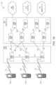
図1Aは、開示される1つまたは複数の実施形態が実装され得る例示的な通信システム100を示す図である。通信システム100は、音声、データ、ビデオ、メッセージング、ブロードキャストなどのコンテンツを複数の無線ユーザに提供する多元接続システムであってよい。通信システム100は、複数の無線ユーザが、無線帯域幅を含めたシステムリソースの共有を通してこのようなコンテンツにアクセスするのを可能にする。例えば、通信システム100は、符号分割多元接続(CDMA)、時分割多元接続(TDMA)、周波数分割多元接続(FDMA)、直交FDMA(OFDMA)、シングルキャリアFDMA(SC-FDMA)、ゼロテイルユニークワード離散フーリエ変換拡散OFDM(ZT-UW-DFT-S-OFDM)、ユニークワードOFDM(UW-OFDM)、リソースブロックフィルタードOFDM、フィルタバンクマルチキャリア(FBMC)など、1つまたは複数のチャネルアクセス方法を採用することができる。 Exemplary Network for Implementation of the Embodiments Figure 1A illustrates an
図1Aに示されるように、通信システム100は、無線送受信ユニット(WTRU)102a、102b、102c、102d、無線アクセスネットワーク(RAN)104、コアネットワーク(CN)106、公衆交換電話網(PSTN)108、インターネット110、および他のネットワーク112を含むことができるが、開示される実施形態が任意の数のWTRU、基地局、ネットワーク、および/またはネットワーク要素を企図することは理解されるであろう。各WTRU102a、102b、102c、102dは、無線環境で動作および/または通信するように構成された任意のタイプのデバイスであってよい。例えば、WTRU102a、102b、102c、102dは、いずれも局(STA)と呼ばれることがあるが、これらは、無線信号を送信および/または受信するように構成されてよく、ユーザ機器(UE)、移動局、固定またはモバイル加入者ユニット、サブスクリプションベースのユニット、ページャ、セルラー電話機、パーソナルデジタルアシスタント(PDA)、スマートフォン、ラップトップ、ノートブック、パーソナルコンピュータ、無線センサ、ホットスポットまたはMi-Fiデバイス、IoTデバイス、腕時計または他のウェアラブル、頭部装着型ディスプレイ(HMD)、車両、ドローン、医療上の機器および応用例(例えば遠隔手術)、産業上のデバイスおよび応用例(例えば、産業上のおよび/または自動化された処理チェーンのコンテキストで動作する、ロボットおよび/または他の無線デバイス)、消費者電子デバイス、商業および/または産業無線ネットワーク上で動作するデバイスなどを含むことができる。WTRU102a、102b、102c、および102dはいずれも、交換可能にUEと呼ばれることがある。As shown in FIG. 1A, the
通信システム100はまた、基地局114aおよび/または基地局114bを含むこともできる。各基地局114a、114bは、WTRU102a、102b、102c、102dのうちの少なくとも1つとワイヤレスにインタフェースして、CN106、インターネット110、および/または他のネットワーク112など1つまたは複数の通信ネットワークへのアクセスを容易にするように構成された、任意のタイプのデバイスであってよい。例えば、基地局114a、114bは、ベーストランシーバステーション(BTS)、Node B、eNode B(eNB)、Home Node B、Home eNode B、次世代Node B(gNode B(gNB)など)、新無線(NR)Node B、サイトコントローラ、アクセスポイント(AP)、無線ルータなどであってよい。基地局114a、114bはそれぞれ単一の要素として描かれているが、基地局114a、114bが任意の数の相互接続された基地局および/またはネットワーク要素を含み得ることは理解されるであろう。The
基地局114aはRAN104の一部であってよく、RAN104はまた、基地局コントローラ(BSC)、無線ネットワークコントローラ(RNC)、中継ノードなど、他の基地局および/またはネットワーク要素(図示せず)を含むこともできる。基地局114aおよび/または基地局114bは、セル(図示せず)と呼ばれ得る1つまたは複数のキャリア周波数上で無線信号を送信および/または受信するように構成されてよい。これらの周波数は、許可済みスペクトル、未許可スペクトル、または許可済みと未許可の組合せのスペクトル中にある場合がある。セルは、比較的固定的であり得るかまたは時間に伴って変化し得る特定の地理エリアに、無線サービスのためのカバレッジを提供することができる。セルはさらに、セルセクタに分割されてよい。例えば、基地局114aに関連付けられたセルが、3つのセクタに分割されてよい。従って、一実施形態では、基地局114aは、3つの送受信機、すなわちセルの各セクタにつき1つの送受信機を備えることができる。実施形態では、基地局114aは、MIMO技術を採用することができ、セルの各セクタにつき複数の送受信機を利用することができる。例えば、ビームフォーミングが使用されて、所望の空間方向で信号が送信および/または受信されてよい。The
基地局114a、114bは、エアインタフェース116を介してWTRU102a、102b、102c、102dのうちの1つまたは複数と通信することができ、エアインタフェース116は、任意の適切な無線通信リンク(例えば、無線周波数(RF)、マイクロ波、センチメートル波、マイクロメートル波、赤外線(IR)、紫外線(UV)、可視光など)であってよい。エアインタフェース116は、任意の適切な無線アクセス技術(RAT)を使用して確立されてよい。The
具体的には、上記のように、通信システム100は多元接続システムであってよく、CDMA、TDMA、FDMA、OFDMA、SC-FDMAなど、1つまたは複数のチャネルアクセス方式を採用することができる。例えば、RAN104中の基地局114a、およびWTRU102a、102b、102cは、ユニバーサルモバイルテレコミュニケーションズシステム(UMTS)地上無線アクセス(UTRA)などの無線技術を実装することができ、これは広帯域CDMA(WCDMA(登録商標))を使用してエアインタフェース116を確立することができる。WCDMAは、高速パケットアクセス(HSPA)および/または進化型HSPA(HSPA+)などの通信プロトコルを含むことができる。HSPAは、高速ダウンリンク(DL)パケットアクセス(HSDPA)および/または高速アップリンク(UL)パケットアクセス(HSUPA)を含むことができる。Specifically, as noted above, the
実施形態では、基地局114aおよびWTRU102a、102b、102cは、進化型UMTS地上無線アクセス(E-UTRA)などの無線技術を実装することができ、これは、ロングタームエボリューション(LTE)および/またはLTEアドバンスト(LTE-A)および/またはLTEアドバンストプロ(LTE-A Pro)を使用してエアインタフェース116を確立することができる。In an embodiment, the
実施形態では、基地局114aおよびWTRU102a、102b、102cは、NR無線アクセスなどの無線技術を実装することができ、これは、NRを使用してエアインタフェース116を確立することができる。In an embodiment, the
実施形態では、基地局114aおよびWTRU102a、102b、102cは、複数の無線アクセス技術を実装することができる。例えば、基地局114aおよびWTRU102a、102b、102cは、デュアルコネクティビティ(DC)原理を使用して、LTE無線アクセスとNR無線アクセスを共に実装することができる。従って、WTRU102a、102b、102cによって利用されるエアインタフェースは、複数のタイプの無線アクセス技術によって、並びに/または複数のタイプの基地局(例えば、eNBおよびgNB)との間の伝送によって特徴付けられ得る。In an embodiment, the
他の実施形態では、基地局114aおよびWTRU102a、102b、102cは、IEEE802.11(すなわち、WiFi(Wireless Fidelity))、IEEE802.16(すなわち、WiMAX(Worldwide Interoperability for Microwave Access))、CDMA2000、CDMA2000 1X、CDMA2000EV-DO、暫定標準2000(IS-2000)、暫定標準95(IS-95)、暫定標準856(IS-856)、移動体通信用グローバルシステム(GSM(登録商標))、GSMエボリューション用高速データレート(EDGE)、GSM EDGE(GERAN)などの無線技術を実装することができる。In other embodiments, the
図1A中の基地局114bは、例えば無線ルータ、Home Node B、Home eNode B、またはアクセスポイントであってよく、事業所、家庭、車両、キャンパス、産業施設、空中回廊(例えば、ドローンによって使用される)、道路など、局所化されたエリアでの無線接続性を容易にするために任意の適切なRATを利用することができる。一実施形態では、基地局114bおよびWTRU102c、102dは、IEEE802.11などの無線技術を実装して、無線ローカルエリアネットワーク(WLAN)を確立することができる。実施形態では、基地局114bおよびWTRU102c、102dは、IEEE802.15などの無線技術を実装して、無線パーソナルエリアネットワーク(WPAN)を確立することができる。さらに別の実施形態では、基地局114bおよびWTRU102c、102dは、セルラーベースのRAT(例えば、WCDMA、CDMA2000、GSM、LTE、LTE-A、LTE-A Pro、NRなど)を利用して、ピコセルまたはフェムトセルを確立することができる。図1Aに示されるように、基地局114bは、インターネット110への直接接続を有することができる。従って、基地局114bは、CN106を介してインターネット110にアクセスすることは必要とされなくてよい。1A may be, for example, a wireless router, Home Node B, Home eNode B, or access point, and may utilize any suitable RAT to facilitate wireless connectivity in a localized area, such as an office, home, vehicle, campus, industrial facility, air corridor (e.g., used by drones), road, etc. In one embodiment, the
RAN104はCN106と通信していてよく、CN106は、音声、データ、アプリケーション、および/またはVoIP(Voice over Internet Protocol)サービスをWTRU102a、102b、102c、102dのうちの1つまたは複数に提供するように構成された任意のタイプのネットワークであってよい。データは、異なるスループット要件、レイテンシ要件、エラー耐性要件、信頼性要件、データスループット要件、モビリティ要件など、変動するサービス品質(QoS)要件を有する場合がある。CN106は、呼制御、料金請求サービス、モバイル位置情報サービス、前払い通話、インターネット接続性、ビデオ配信などを提供することができ、かつ/または、ユーザ認証などの高レベルなセキュリティ機能を実施することができる。図1Aには示されていないが、RAN104および/またはCN106は、RAN104と同じRATまたは異なるRATを採用する他のRANと直接的または間接的に通信していてもよいことは理解されるであろう。例えば、CN106は、NR無線技術を利用しているであろうRAN104に接続されるのに加えて、GSM、UMTS、CDMA2000、WiMAX、E-UTRA、またはWiFi無線技術を採用する別のRAN(図示せず)と通信していてもよい。The RAN 104 may be in communication with the
CN106はまた、WTRU102a、102b、102c、102dがPSTN108、インターネット110、および/または他のネットワーク112にアクセスするためのゲートウェイとしての働きをすることもできる。PSTN108は、単純旧式電話サービス(POTS)を提供する回線交換電話網を含むことができる。インターネット110は、TCP/IPインターネットプロトコルスイート中のTCP、UDP、および/またはIPなど、共通の通信プロトコルを使用する相互接続されたコンピュータネットワークおよびデバイスの地球規模のシステムを含むことができる。ネットワーク112は、他のサービスプロバイダによって所有および/または運営される、有線および/または無線通信ネットワークを含むことができる。例えば、ネットワーク112は、RAN104と同じRATまたは異なるRATを採用し得る1つまたは複数のRANに接続された別のCNを含むことができる。The
通信システム100中のWTRU102a、102b、102c、102dのいくつかまたは全ては、マルチモード能力を備えることができる(例えば、WTRU102a、102b、102c、102dは、異なる無線リンクを介して異なる無線ネットワークと通信するために、複数の送受信機を備えることができる)。例えば、図1Aに示されるWTRU102cは、セルラーベースの無線技術を採用し得る基地局114aと通信し、IEEE802無線技術を採用し得る基地局114bと通信するように構成されてよい。Some or all of the
図1Bは、例示的なWTRU102を示すシステム図である。図1Bに示されるように、WTRU102は、とりわけ、プロセッサ118、送受信機120、送受信要素122、スピーカ/マイクロホン124、キーパッド126、ディスプレイ/タッチパッド128、非リムーバブルメモリ130、リムーバブルメモリ132、電源134、GPSチップセット136、および/または他の周辺装置138を備えることができる。WTRU102が実施形態との一貫性を維持しながら前述の要素の任意のサブコンビネーションを備え得ることは理解されるであろう。FIG. 1B is a system diagram illustrating an
プロセッサ118は、汎用プロセッサ、専用プロセッサ、従来型プロセッサ、デジタル信号プロセッサ(DSP)、複数のマイクロプロセッサ、DSPコアと連携した1つまたは複数のマイクロプロセッサ、コントローラ、マイクロコントローラ、特定用途向け集積回路(ASIC)、フィールドプログラマブルゲートアレイ(FPGA)、他の任意のタイプの集積回路(IC)、ステートマシンなどであってよい。プロセッサ118は、信号符号化、データ処理、電力制御、入出力処理、および/または、WTRU102が無線環境で動作するのを可能にする他の任意の機能を実施することができる。プロセッサ118は送受信機120に結合されてよく、送受信機120は送受信要素122に結合されてよい。図1Bはプロセッサ118と送受信機120を別々のコンポーネントとして描いているが、プロセッサ118と送受信機120は電子パッケージまたはチップ中で統合されてもよいことを理解されたい。The
送受信要素122は、エアインタフェース116を介して基地局(例えば基地局114a)との間で信号を送信または受信するように構成されてよい。例えば、一実施形態では、送受信要素122は、RF信号を送信および/または受信するように構成されたアンテナであってよい。実施形態では、送受信要素122は、例えばIR、UV、または可視光信号を送信および/または受信するように構成されたエミッタ/検出器であってよい。さらに別の実施形態では、送受信要素122は、RF信号と光信号との両方を送信および/または受信するように構成されてよい。送受信要素122が任意の組合せの無線信号を送信および/または受信するように構成されてよいことは理解されるであろう。The transmit/receive
図1Bでは送受信要素122が単一の要素として描かれているが、WTRU102は、任意の数の送受信要素122を備えることができる。より具体的には、WTRU102は、MIMO技術を採用することができる。従って、一実施形態では、WTRU102は、エアインタフェース116を介して無線信号を送受信するために、2つ以上の送受信要素122(例えば、複数のアンテナ)を備えることができる。Although the transmit/receive
送受信機120は、送受信要素122によって送信されることになる信号を変調するように、かつ、送受信要素122によって受信された信号を復調するように構成されてよい。上記のように、WTRU102はマルチモード能力を有することができる。従って、送受信機120は、例えばNRおよびIEEE802.11など複数のRATを介してWTRU102が通信するのを可能にするために、複数の送受信機を備えることができる。The
WTRU102のプロセッサ118は、スピーカ/マイクロホン124、キーパッド126、および/または、ディスプレイ/タッチパッド128(例えば、液晶ディスプレイ(LCD)ディスプレイユニット若しくは有機発光ダイオード(OLED)ディスプレイユニット)に結合されてよく、これらからユーザ入力データを受け取ることができる。プロセッサ118はまた、スピーカ/マイクロホン124、キーパッド126、および/またはディスプレイ/タッチパッド128にユーザデータを出力することができる。また、プロセッサ118は、非リムーバブルメモリ130および/またはリムーバブルメモリ132など任意のタイプの適切なメモリの情報にアクセスすること、並びにこのようなメモリにデータを記憶することができる。非リムーバブルメモリ130は、RAM、ROM、ハードディスク、または他の任意のタイプのメモリ記憶デバイスを含むことができる。リムーバブルメモリ132は、SIMカード、メモリスティック、セキュアデジタル(SD)メモリカードなどを含むことができる。他の実施形態では、プロセッサ118は、サーバやホームコンピュータ(図示せず)上のメモリなど、WTRU102上に物理的に位置しないメモリからの情報にアクセスすること、およびこのようなメモリにデータを記憶することができる。The
プロセッサ118は、電源134から電力を受け取ることができ、WTRU102中の他のコンポーネントへの電力の分配および/または制御を行うように構成されてよい。電源134は、WTRU102に電力供給するための任意の適切なデバイスであってよい。例えば、電源134は、1つまたは複数の乾電池(例えば、ニッケルカドミウム(NiCd)、ニッケル銅(NiZn)、ニッケルメタルハイドライド(NiMH)、リチウムイオン(Li-ion)など)、太陽電池、燃料電池などを含むことができる。The
プロセッサ118はGPSチップセット136にも結合されてよく、GPSチップセット136は、WTRU102の現在位置に関する位置情報(例えば、経度と緯度)を提供するように構成されてよい。GPSチップセット136からの情報に加えてまたはそれに代えて、WTRU102は、エアインタフェース116を介して基地局(例えば、基地局114a、114b)から位置情報を受け取ること、および/または、2つ以上の近隣基地局から受信される信号のタイミングに基づいてその位置を決定することもできる。WTRU102が実施形態との一貫性を維持しながら任意の適切な位置決定方法によって位置情報を取得できることは理解されるであろう。The
プロセッサ118はさらに、他の周辺装置138にも結合されてよく、周辺装置138は、追加の特徴、機能、および/または有線若しくは無線接続性を提供する1つまたは複数のソフトウェアおよび/またはハードウェアモジュールを含むことができる。例えば、周辺装置138は、加速度計、電子コンパス、衛星送受信機、デジタルカメラ(写真および/またはビデオ用)、USBポート、振動デバイス、テレビジョン送受信機、ハンズフリーヘッドセット、Bluetooth(登録商標)モジュール、周波数変調(FM)無線ユニット、デジタル音楽プレーヤ、メディアプレーヤ、ビデオゲームプレーヤモジュール、インターネットブラウザ、仮想現実および/または拡張現実(VR/AR)デバイス、アクティビティトラッカなどを含むことができる。周辺装置138は、1つまたは複数のセンサを含むことができる。センサは、ジャイロスコープ、加速度計、ホール効果センサ、磁力計、配向センサ、近接センサ、温度センサ、時間センサ、ジオロケーションセンサ、高度計、光センサ、タッチセンサ、磁力計、気圧計、ジェスチャセンサ、バイオメトリックセンサ、湿度センサなどのうちの1つまたは複数であってよい。The
WTRU102は、(例えば、UL(例えば送信用)とDL(例えば受信用)の両方について特定のサブフレームに関連付けられた)信号のいくつかまたは全ての送信および受信が並行および/または同時であり得る、全二重無線を含むことができる。全二重無線は、干渉管理ユニットを含むことができ、それにより、ハードウェア(例えばチョーク)を介して、またはプロセッサ(例えば、別個のプロセッサ(図示せず)若しくはプロセッサ118)を介した信号処理を介して、自己干渉が低減されるかまたはほぼ除去される。実施形態では、WTRU102は、信号のいくつかまたは全ての送信および受信(例えば、UL(例えば送信用)とDL(例えば受信用)のいずれかについて特定のサブフレームに関連付けられた)が行われる、半二重無線を含むことができる。
図1Cは、実施形態によるRAN104およびCN106を示すシステム図である。上記のように、RAN104は、E-UTRA無線技術を採用して、エアインタフェース116を介してWTRU102a、102b、102cと通信することができる。RAN104はまた、CN106とも通信していてよい。1C is a system diagram illustrating the
RAN104はeNode-B160a、160b、160cを含むことができるが、RAN104が実施形態との一貫性を維持しながら任意の数のeNode-Bを含み得ることは理解されるであろう。eNode-B160a、160b、160cはそれぞれ、エアインタフェース116を介してWTRU102a、102b、102cと通信するための1つまたは複数の送受信機を備えることができる。一実施形態では、eNode-B160a、160b、160cは、MIMO技術を採用することができる。従って、例えばeNode-B160aは、複数のアンテナを使用して、WTRU102aとの間で無線信号を送信および/または受信することができる。The
各eNode-B160a、160b、160cは、特定のセル(図示せず)に関連付けられてよく、無線リソース管理決定、ハンドオーバ決定、ULおよび/またはDLにおけるユーザのスケジューリングなどを扱うように構成されてよい。図1Cに示されるように、eNode-B160a、160b、160cは、X2インタフェースを介して相互と通信することができる。Each eNode-
図1Cに示されるCN106は、モビリティ管理エンティティ(MME)162、サービングゲートウェイ(SGW)164、およびパケットデータネットワーク(PDN)ゲートウェイ(PGW)166を含むことができる。前述の要素はCN106の一部として描かれているが、これらの要素はいずれもCNオペレータ以外のエンティティによって所有および/または運営されてもよいことは理解されるであろう。
MME162は、S1インタフェースを介してRAN104中の各eNode-B160a、160b、160cに接続されてよく、制御ノードとしての働きをすることができる。例えば、MME162は、WTRU102a、102b、102cのユーザを認証すること、ベアラアクティブ化/非アクティブ化、WTRU102a、102b、102cの初期アタッチ中に特定のサービングゲートウェイを選択することなどを担うことができる。MME162は、RAN104と、GSMおよび/またはWCDMAなど他の無線技術を採用する他のRAN(図示せず)との間で切り替えるための制御プレーン機能を提供することができる。The
SGW164は、S1インタフェースを介してRAN104中の各eNode B160a、160b、160cに接続されてよい。SGW164は一般に、WTRU102a、102b、102cとの間でユーザデータパケットをルーティングおよび転送することができる。SGW164は、eNode B間ハンドオーバ中にユーザプレーンをアンカリングすること、WTRU102a、102b、102cにDLデータが利用可能であるときにページングをトリガすること、WTRU102a、102b、102cのコンテキストを管理および記憶することなど、他の機能を実施することもできる。The
SGW164はPGW166に接続されてよく、PGW166は、インターネット110などのパケット交換ネットワークへのアクセスをWTRU102a、102b、102cに提供して、WTRU102a、102b、102cとIP対応デバイスとの間の通信を容易にすることができる。The
CN106は、他のネットワークとの通信を容易にすることができる。例えば、CN106は、PSTN108などの回線交換ネットワークへのアクセスをWTRU102a、102b、102cに提供して、WTRU102a、102b、102cと従来型の陸線通信デバイスとの間の通信を容易にする。例えば、CN106は、CN106とPSTN108との間のインタフェースとしての働きをするIPゲートウェイ(例えば、IPマルチメディアサブシステム(IMS)サーバ)を含むか、またはこのIPゲートウェイと通信することができる。CN106は、他のサービスプロバイダによって所有および/または運営される他の有線および/または無線ネットワークを含み得る他のネットワーク112へのアクセスを、WTRU102a、102b、102cに提供することもできる。
図1A~1DではWTRUが無線端末として記述されているが、いくつかの代表的な実施形態では、このような端末が通信ネットワークとの有線通信インタフェースを(例えば、一時的にまたは永続的に)使用し得ることが企図される。Although the WTRUs are depicted as wireless terminals in Figures 1A-1D, it is contemplated that in some representative embodiments such terminals may use a wired communications interface (e.g., temporarily or permanently) with a communications network.
代表的な実施形態では、他のネットワーク112はWLANであってよい。In a representative embodiment, the
インフラストラクチャベーシックサービスセット(BSS)モードのWLANは、BSSのためのアクセスポイント(AP)と、APに関連付けられた1つまたは複数の局(STA)とを有することができる。APは、BSSへのトラフィックおよび/またはBSSからのトラフィックを搬送する配信システム(DS)または別のタイプの有線/無線ネットワークへの、アクセスまたはインタフェースを有することができる。BSS外から生じたSTAへのトラフィックは、APを通して到着してよく、STAに送られてよい。STAから生じたBSS外の宛先へのトラフィックは、それぞれの宛先に送達されるようにAPに送られてよい。BSS内のSTA間のトラフィックは、APを通して送られてよく、例えばこの場合、ソースSTAがAPにトラフィックを送り、APが宛先STAにトラフィックを送達することができる。BSS内のSTA間のトラフィックは、ピアツーピアトラフィックと見なされる、かつ/または呼ばれることがある。ピアツーピアトラフィックは、直接リンクセットアップ(DLS)を用いてソースSTAと宛先STAとの間で(例えば直接に)送られてよい。いくつかの代表的な実施形態では、DLSは、802.11e DLSまたは802.11zトンネルド(tunneled)DLS(TDLS)を使用することができる。独立BSS(IBSS)モードを使用するWLANは、APを有さなくてよく、IBSS内の、またはIBSSを使用するSTA(例えば、全てのSTA)は、相互と直接に通信することができる。IBSS通信モードは、本明細書では「アドホック」通信モードと呼ばれることがある。A WLAN in infrastructure basic service set (BSS) mode may have an access point (AP) for the BSS and one or more stations (STAs) associated with the AP. The AP may have access or an interface to a distribution system (DS) or another type of wired/wireless network that carries traffic to and/or from the BSS. Traffic to the STA originating from outside the BSS may arrive through the AP and be sent to the STA. Traffic originating from the STA to a destination outside the BSS may be sent to the AP to be delivered to the respective destination. Traffic between STAs within the BSS may be sent through the AP, e.g., where the source STA may send traffic to the AP, which in turn may deliver traffic to the destination STA. Traffic between STAs within the BSS may be considered and/or referred to as peer-to-peer traffic. Peer-to-peer traffic may be sent (e.g., directly) between the source and destination STAs using a direct link setup (DLS). In some representative embodiments, the DLS may use 802.11e DLS or 802.11z tunneled DLS (TDLS). A WLAN using an Independent BSS (IBSS) mode may not have an AP, and STAs (e.g., all STAs) within or using an IBSS may communicate directly with each other. The IBSS communication mode may be referred to herein as an "ad-hoc" communication mode.
802.11acインフラストラクチャ動作モードまたは類似の動作モードを使用するとき、APは、プライマリチャネルなどの固定チャネル上でビーコンを送信することができる。プライマリチャネルは、固定幅(例えば、20MHz幅の帯域幅)または動的に設定される幅であってよい。プライマリチャネルは、BSSの動作チャネルであってよく、APとの接続を確立するためにSTAによって使用されてよい。いくつかの代表的な実施形態では、例えば802.11システム中で、衝突回避機能付きキャリアセンス多元接続(Carrier Sense Multiple Access with Collision Avoidance)(CSMA/CA)が実装されてよい。CSMA/CAでは、APを含めて、STA(例えば、あらゆるSTA)は、プライマリチャネルを感知することができる。プライマリチャネルがビジーであることが特定のSTAによって感知/検出および/または決定された場合、特定のSTAはバックオフすることができる。所与のBSS中で、いずれかの所与の時に1つのSTA(例えば、1つの局のみ)が送信することができる。When using an 802.11ac infrastructure mode of operation or a similar mode of operation, an AP may transmit a beacon on a fixed channel, such as a primary channel. The primary channel may be a fixed width (e.g., a 20 MHz wide bandwidth) or a dynamically set width. The primary channel may be the operating channel of the BSS and may be used by STAs to establish a connection with the AP. In some representative embodiments, for example in an 802.11 system, Carrier Sense Multiple Access with Collision Avoidance (CSMA/CA) may be implemented. In CSMA/CA, STAs (e.g., every STA), including the AP, may sense the primary channel. If a particular STA senses/detects and/or determines that the primary channel is busy, the particular STA may back off. In a given BSS, only one STA (e.g., only one station) may transmit at any given time.
ハイスループット(HT)STAは、例えばプライマリ20MHzチャネルと隣接または非隣接20MHzチャネルとを組み合わせて40MHz幅のチャネルを形成することを介して、40MHz幅のチャネルを通信に使用することができる。High throughput (HT) STAs can use 40 MHz wide channels for communication, for example, by combining a primary 20 MHz channel with adjacent or non-adjacent 20 MHz channels to form a 40 MHz wide channel.
ベリーハイスループット(VHT)STAは、20MHz、40MHz、80MHz、および/または160MHz幅のチャネルをサポートすることができる。40MHzおよび/または80MHzチャネルは、連続した20MHzチャネルを結合することによって形成されてよい。160MHzチャネルは、8つの連続した20MHzチャネルを結合することによって、または2つの非連続80MHzチャネルを結合することによって形成されてよく、後者は80+80構成と呼ばれることがある。80+80構成の場合、データは、チャネル符号化後にセグメントパーサの中を通されてよく、セグメントパーサはデータを2つのストリームに分割することができる。各ストリームに対して別々に、逆高速フーリエ変換(IFFT)処理および時間領域処理が行われてよい。ストリームは、2つの80MHzチャネル上にマッピングされてよく、データは送信側STAによって送信されてよい。受信側STAの受信機では、80+80構成の場合の前述の動作が反転されてよく、結合されたデータは媒体アクセス制御(MAC)に送られてよい。A Very High Throughput (VHT) STA can support 20 MHz, 40 MHz, 80 MHz, and/or 160 MHz wide channels. The 40 MHz and/or 80 MHz channels may be formed by combining contiguous 20 MHz channels. The 160 MHz channel may be formed by combining eight contiguous 20 MHz channels or by combining two non-contiguous 80 MHz channels, the latter sometimes referred to as an 80+80 configuration. For the 80+80 configuration, the data may be passed through a segment parser after channel encoding, which may split the data into two streams. Inverse Fast Fourier Transform (IFFT) and time domain processing may be performed separately for each stream. The streams may be mapped onto two 80 MHz channels, and the data may be transmitted by the transmitting STA. At the receiver of the receiving STA, the above operations for the 80+80 configuration may be reversed and the combined data may be sent to the medium access control (MAC).
サブ1GHz動作モードが、802.11afおよび802.11ahによってサポートされる。802.11afおよび802.11ahでは、チャネル動作帯域幅およびキャリアは、802.11nおよび802.11acで使用されるものに対して相対的に低減される。802.11afは、TVホワイトスペース(TVWS)スペクトル中の5MHz、10MHz、および20MHz帯域幅をサポートし、802.11ahは、非TVWSスペクトルを使用して1MHz、2MHz、4MHz、8MHz、および16MHz帯域幅をサポートする。代表的な実施形態によれば、802.11ahは、マクロカバレッジエリア中のマシンタイプ通信(MTC)など、メータータイプ制御/MTCをサポートすることができる。MTCデバイスは、いくつかの能力、例えば、いくつかのおよび/または限定された帯域幅のサポート(例えば、これらのサポートのみ)を含めた限定された能力を有することができる。MTCデバイスは、閾値よりも長い電池寿命を有する電池を備えることができる(例えば、非常に長い電池寿命を維持するために)。Sub-1 GHz operating modes are supported by 802.11af and 802.11ah. In 802.11af and 802.11ah, the channel operating bandwidths and carriers are reduced relative to those used in 802.11n and 802.11ac. 802.11af supports 5 MHz, 10 MHz, and 20 MHz bandwidths in the TV White Space (TVWS) spectrum, while 802.11ah supports 1 MHz, 2 MHz, 4 MHz, 8 MHz, and 16 MHz bandwidths using non-TVWS spectrum. According to a representative embodiment, 802.11ah can support meter type control/MTC, such as machine type communication (MTC) in macro coverage areas. MTC devices can have some capabilities, including, for example, some and/or limited bandwidth support (e.g., only these support). The MTC device may have a battery with a battery life greater than a threshold (e.g., to maintain a very long battery life).
WLANシステムは、802.11n、802.11ac、802.11af、および802.11ahなど複数のチャネルおよびチャネル帯域幅をサポートすることができ、このWLANシステムは、プライマリチャネルとして指定され得るチャネルを含む。プライマリチャネルは、BSS中の全てのSTAによってサポートされる最大共通動作帯域幅に等しい帯域幅を有することができる。プライマリチャネルの帯域幅は、BSS中で動作している全てのSTAのうちの最小帯域幅動作モードをサポートするSTAによって設定および/または制限されてよい。802.11ahの例では、APとBSS中の他のSTAとが2MHz、4MHz、8MHz、16MHz、および/または他のチャネル帯域幅動作モードをサポートする場合であっても、プライマリチャネルは、1MHzモードをサポートする(例えば、それだけをサポートする)STA(例えば、MTCタイプのデバイス)のために1MHz幅であってよい。キャリア感知および/またはネットワーク割振りベクトル(NAV)設定は、プライマリチャネルのステータスに依存し得る。例えばSTA(1MHz動作モードのみをサポートする)がAPに送信しているせいで、プライマリチャネルがビジーである場合は、利用可能な周波数帯域の大部分が遊休のままであっても、利用可能な全ての周波数帯域はビジーであると見なされてよい。A WLAN system may support multiple channels and channel bandwidths, such as 802.11n, 802.11ac, 802.11af, and 802.11ah, including a channel that may be designated as a primary channel. The primary channel may have a bandwidth equal to the maximum common operating bandwidth supported by all STAs in the BSS. The bandwidth of the primary channel may be set and/or limited by the STA that supports the smallest bandwidth operating mode of all STAs operating in the BSS. In an 802.11ah example, the primary channel may be 1 MHz wide for STAs (e.g., MTC type devices) that support (e.g., only) the 1 MHz mode, even if the AP and other STAs in the
米国では、802.11ahによって使用され得る利用可能な周波数帯域は、902MHzから928MHzである。韓国では、利用可能な周波数帯域は917.5MHzから923.5MHzである。日本では、利用可能な周波数帯域は916.5MHzから927.5MHzである。802.11ahに利用可能な総帯域幅は、国コードに応じて6MHzから26MHzである。In the United States, the available frequency bands that can be used by 802.11ah are 902MHz to 928MHz. In South Korea, the available frequency bands are 917.5MHz to 923.5MHz. In Japan, the available frequency bands are 916.5MHz to 927.5MHz. The total bandwidth available for 802.11ah is 6MHz to 26MHz depending on the country code.
図1Dは、実施形態によるRAN104およびCN106を示すシステム図である。上記のように、RAN104は、NR無線技術を採用して、エアインタフェース116を介してWTRU102a、102b、102cと通信することができる。RAN104はまた、CN106とも通信していてよい。FIG. 1D is a system diagram illustrating the
RAN104はgNB180a、180b、180cを含むことができるが、RAN104が実施形態との一貫性を維持したまま任意の数のgNBを含み得ることは理解されるであろう。gNB180a、180b、180cはそれぞれ、エアインタフェース116を介してWTRU102a、102b、102cと通信するための1つまたは複数の送受信機を備えることができる。一実施形態では、gNB180a、180b、180cは、MIMO技術を実装することができる。例えば、gNB180a、108bは、ビームフォーミングを利用して、gNB180a、180b、180cとの間で信号を送信および/または受信することができる。従って、例えばgNB180aは、複数のアンテナを使用して、WTRU102aとの間で無線信号を送信および/または受信することができる。実施形態では、gNB180a、180b、180cは、キャリアアグリゲーション技術を実装することができる。例えば、gNB180aは、複数のコンポーネントキャリアをWTRU102a(図示せず)に送信することができる。これらのコンポーネントキャリアのサブセットが未許可スペクトル上にあり、残りのコンポーネントキャリアが許可済みスペクトル上にあってよい。実施形態では、gNB180a、180b、180cは、多地点協調(CoMP)技術を実装することができる。例えば、WTRU102aは、gNB180aとgNB180b(および/またはgNB180c)とから協調送信を受信することができる。
WTRU102a、102b、102cは、スケーラブルヌメロロジー(scalable numerology)に関連付けられた伝送を使用してgNB180a、180b、180cと通信することができる。例えば、OFDMシンボルスペーシングおよび/またはOFDMサブキャリアスペーシングは、異なる伝送、異なるセル、および/または無線伝送スペクトルの異なる部分によって変動し得る。WTRU102a、102b、102cは、様々なまたはスケーラブルな長さのサブフレームまたは送信時間間隔(TTI)(例えば、変動する数のOFDMシンボル、および/または永続的な変動する長さの絶対時間を含む)を使用して、gNB180a、180b、180cと通信することができる。
gNB180a、180b、180cは、スタンドアロン構成および/または非スタンドアロン構成でWTRU102a、102b、102cと通信するように構成されてよい。スタンドアロン構成では、WTRU102a、102b、102cは、他のRAN(例えば、eNode-B160a、160b、160cなど)にもまたアクセスすることなく、gNB180a、180b、180cと通信することができる。スタンドアロン構成では、WTRU102a、102b、102cは、gNB180a、180b、180cのうちの1つまたは複数をモビリティアンカーポイントとして利用することができる。スタンドアロン構成では、WTRU102a、102b、102cは、未許可帯域中の信号を使用してgNB180a、180b、180cと通信することができる。非スタンドアロン構成では、WTRU102a、102b、102cは、eNode-B160a、160b、160cなど別のRANとも通信/接続しながら、gNB180a、180b、180cと通信/接続することができる。例えば、WTRU102a、102b、102cは、DC原理を実装して、ほぼ同時に1つまたは複数のgNB180a、180b、180cおよび1つまたは複数のeNode-B160a、160b、160cと通信することができる。非スタンドアロン構成では、eNode-B160a、160b、160cは、WTRU102a、102b、102cのためのモビリティアンカーとしての働きをすることができ、gNB180a、180b、180cは、WTRU102a、102b、102cにサービスするための追加のカバレッジおよび/またはスループットを提供することができる。The
各gNB180a、180b、180cは、特定のセル(図示せず)に関連付けられてよく、無線リソース管理決定、ハンドオーバ決定、ULおよび/またはDLにおけるユーザのスケジューリング、ネットワークスライシングのサポート、DC、NRとE-UTRAとの間の相互作用、ユーザプレーン機能(UPF)184a、184bに向けたユーザプレーンデータのルーティング、アクセスおよびモビリティ管理機能(AMF)182a、182bに向けた制御プレーン情報のルーティングなどを扱うように構成されてよい。図1Dに示されるように、gNB180a、180b、180cは、Xnインタフェースを介して相互と通信することができる。Each
図1Dに示されるCN106は、少なくとも1つのAMF182a、182b、少なくとも1つのUPF184a、184b、少なくとも1つのセッション管理機能(SMF)183a、183b、および場合によりデータネットワーク(DN)185a、185bを含むことができる。前述の要素はCN106の一部として描かれているが、これらの要素はいずれもCNオペレータ以外のエンティティによって所有および/または運営されてもよいことは理解されるであろう。
AMF182a、182bは、N2インタフェースを介してRAN104中のgNB180a、180b、180cのうちの1つまたは複数に接続されてよく、制御ノードとしての働きをすることができる。例えば、AMF182a、182bは、WTRU102a、102b、102cのユーザを認証すること、ネットワークスライシングのサポート(例えば、異なる要件を有する異なるプロトコルデータユニット(PDU)セッションの処理)、特定のSMF183a、183bの選択、登録エリアの管理、非アクセス層(NAS)シグナリングの終端、モビリティ管理などを担うことができる。ネットワークスライシングは、WTRU102a、102b、102cによって利用されているサービスのタイプに基づいてWTRU102a、102b、102cのためのCNサポートをカスタマイズするために、AMF182a、182bによって使用されてよい。例えば、超高信頼低遅延(URLLC)アクセスに依拠するサービス、高速大容量モバイルブロードバンド(eMBB)アクセスに依拠するサービス、MTCアクセスのためのサービスなど、異なる使用ケースに対して、異なるネットワークスライスが確立されてよい。AMF182a、182bは、RAN104と、LTE、LTE-A、LTE-A Pro、および/または非3GPPアクセス技術(WiFi等)など他の無線技術を採用する他のRAN(図示せず)との間で切り替えるための制御プレーン機能を提供することができる。The
SMF183a、183bは、は、N11インタフェースを介してCN106中のAMF182a、182bに接続されてよい。SMF183a、183bはまた、N4インタフェースを介してCN106中のUPF184a、184bにも接続されてよい。SMF183a、183bは、UPF184a、184bを選択および制御し、UPF184a、184bを介したトラフィックのルーティングを構成することができる。SMF183a、183bは、UE IPアドレスの管理および割振り、PDUセッションの管理、ポリシ施行およびQoSの制御、DLデータ通知の提供など、他の機能を実施することもできる。PDUセッションタイプは、IPベース、非IPベース、イーサネット(登録商標)ベースなどであってよい。The
UPF184a、184bは、N3インタフェースを介してRAN104中のgNB180a、180b、180cのうちの1つまたは複数に接続されてよく、これは、インターネット110などのパケット交換ネットワークへのアクセスをWTRU102a、102b、102cに提供して、WTRU102a、102b、102cとIP対応デバイスとの間の通信を容易にすることができる。UPF184a、184bは、パケットのルーティングおよび転送、ユーザプレーンポリシの施行、マルチホームPDUセッションのサポート、ユーザプレーンQoSの処理、DLパケットのバッファリング、モビリティアンカリングの提供など、他の機能を実施することもできる。The
CN106は、他のネットワークとの通信を容易にする。例えば、CN106は、CN106とPSTN108との間のインタフェースとしての働きをするIPゲートウェイ(例えば、IPマルチメディアサブシステム(IMS)サーバ)を含むか、またはこのIPゲートウェイと通信することができる。CN106は、他のサービスプロバイダによって所有および/または運営される他の有線および/または無線ネットワークを含み得る他のネットワーク112へのアクセスを、WTRU102a、102b、102cに提供することができる。一実施形態では、WTRU102a、102b、102cは、UPF184a、184bへのN3インタフェース、およびUPF184a、184bとDN185a、185bとの間のN6インタフェースを介して、UPF184a、184bを通してローカルDN185a、185bに接続されてよい。The
図1A~1Dと、図1A~1Dについての対応する記述とに鑑みて、WTRU102a~d、基地局114a~b、eNode-B160a~c、MME162、SGW164、PGW166、gNB180a~c、AMF182a~b、UPF184a~b、SMF183a~b、DN185a~bおよび/または本明細書に記載の他の任意のデバイスのうちの1つまたは複数に関する、本明細書に記載の機能のうちの1つ若しくは複数または全てが、1つまたは複数のエミュレーションデバイス(図示せず)によって実施されてよい。エミュレーションデバイスは、本明細書に記載の機能のうちの1つ若しくは複数または全てをエミュレートするように構成された1つまたは複数のデバイスであってよい。例えば、エミュレーションデバイスは、他のデバイスをテストするため、並びに/またはネットワークおよび/若しくはWTRU機能をシミュレートするために使用されてよい。1A-1D and the corresponding description thereof, one or more or all of the functions described herein for one or more of the
エミュレーションデバイスは、研究室環境および/またはオペレータネットワーク環境で他のデバイスに対する1つまたは複数のテストを実装するように設計されてよい。例えば、1つまたは複数のエミュレーションデバイスは、通信ネットワーク内の他のデバイスをテストするために、有線および/または無線通信ネットワークの一部として完全にまたは部分的に実装および/または展開されて、1つ若しくは複数または全ての機能を実施することができる。1つまたは複数のエミュレーションデバイスは、有線および/または無線通信ネットワークの一部として一時的に実装/展開されて、1つ若しくは複数または全ての機能を実施することができる。エミュレーションデバイスは、テストの目的で、かつ/または無線経由の無線通信を使用したテスト実施の目的で、別のデバイスに直接に結合されてよい。The emulation device may be designed to implement one or more tests on other devices in a laboratory environment and/or an operator network environment. For example, one or more emulation devices may be fully or partially implemented and/or deployed as part of a wired and/or wireless communication network to perform one or more or all functions to test other devices in the communication network. One or more emulation devices may be temporarily implemented/deployed as part of a wired and/or wireless communication network to perform one or more or all functions. The emulation device may be directly coupled to another device for testing purposes and/or for performing tests using wireless communication over the air.
1つまたは複数のエミュレーションデバイスは、有線および/または無線通信ネットワークの一部として実装/展開されずに、全ての機能を含めた1つまたは複数の機能を実施することもできる。例えば、エミュレーションデバイスは、1つまたは複数のコンポーネントのテストを実装するために、テスト用研究室におけるテスト用シナリオで、かつ/または非展開(例えばテスト用の)有線および/若しくは無線通信ネットワークにおけるテスト用シナリオで、利用されてよい。1つまたは複数のエミュレーションデバイスは、テスト機器であってよい。直接RF結合、および/または、RF回路(例えば、1つ若しくは複数のアンテナを備え得る)を介した無線通信が、エミュレーションデバイスによって使用されて、データが送信および/または受信されてよい。The emulation device or devices may perform one or more functions, including all functions, without being implemented/deployed as part of a wired and/or wireless communication network. For example, the emulation device may be utilized in a test scenario in a test lab and/or in a non-deployed (e.g., test) wired and/or wireless communication network to implement testing of one or more components. The emulation device or devices may be test equipment. Direct RF coupling and/or wireless communication via RF circuitry (e.g., which may include one or more antennas) may be used by the emulation device to transmit and/or receive data.
詳細な説明
無線遠隔通信のカバレッジ範囲を改善する方法の1つは、π/2-BPSK変調と周波数領域スペクトルシェーピング(FDSS)とを伴う離散フーリエ変換(DFT)-拡散直交周波数分割多重化(OFDM)を使用して、送信信号のピーク対平均電力比(PAPR)またはキュービックメトリック(CM)を低減することである。 DETAILED DESCRIPTION One method to improve the coverage range of wireless telecommunications is to use Discrete Fourier Transform (DFT)-spread Orthogonal Frequency Division Multiplexing (OFDM) with π/2-BPSK modulation and Frequency Domain Spectral Shaping (FDSS) to reduce the Peak-to-Average Power Ratio (PAPR) or Cubic Metric (CM) of the transmitted signal.
図2は、周波数領域スペクトルシェーピング(FDSS)を伴うπ/2二位相シフトキーイング(BPSK)離散フーリエ変換(DFT)拡散直交周波数分割多重化(OFDM)の、2つの異なる実装形態200、220の例証である。第1のブロック図200では、ビット202が、π/2-BPSK変調204によって変調される。π/2-BPSK変調204は、シーケンス中の前の要素の関数であってもよく、または他の要素から独立していてもよい。いくつかの実装形態では、π/2-BPSK変調は、式1に示されるように定義される。Figure 2 illustrates two

上式で、s(bi)はπ/2-BPSKシンボルであり、biはシーケンス中のi番目のシンボルであり、i=0はシーケンスの第1の要素に対応する。変調後、生成された変調シンボルは、長さMのDFT206でプリコーディングされてよい。次に、FDSS操作208のために、プリコーディングされたベクトルの各要素に、フィルタによって決定された重みが乗算される。例えば、フィルタリング係数が[0.28 1 0.28]である場合、重みはDFT([1 0.28 01,M-3 0.28],M)として得られてよく、ここで、DFT(a,M)は、ベクトルaのMポイントDFTであり、0M,Kは、M行K列のゼロ行列である。FDSS操作の後、シェーピングされたプリコーディング済みベクトルの逆DFT(IDFT)210が計算され、得られたベクトルは、RFチェーンを通して送信されてよい。 where s(bi ) is a π/2-BPSK symbol, bi is the i-th symbol in the sequence, and i=0 corresponds to the first element of the sequence. After modulation, the generated modulation symbols may be precoded with a
図2の第2のブロック図220では、ビット222が変調され(224)、FDSS操作226が実施され、次いでDFT228を用いたプリコーディングが行われる。第1のブロック図200とは対照的に、第2のブロック図220は、FDSS226を時間領域で実装する。このようにして、変調シンボルが生成された(224)後、変調シンボルは、フィルタリング係数を用いて巡回畳込みされる。例えば、変調シンボルは、[1 0.28 0M-3,1 0.28]を用いて巡回畳込みされる。このような方式の主要な利益は、増大されたPAPRおよびCM性能をもたらすことができる。IDFT230が計算され、得られたベクトルは、RFチェーンを通して送信されてよい。 In the second block diagram 220 of FIG. 2, the
いくつかの実装形態では、π/2-BPSK DFT-拡散OFDMベースのデータ共有チャネルについて、インタリーブされる復調基準信号(DMRS)構造が採用され、これはタイプ1と呼ばれることがある。データ共有チャネルは、ダウンリンク共有チャネル(DL-SCH)およびアップリンク共有チャネル(UL-SCH)を含むことができる。他の共有チャネルが使用されてもよい。In some implementations, for the π/2-BPSK DFT-spread OFDM-based data sharing channel, an interleaved demodulation reference signal (DMRS) structure is adopted, which may be referred to as
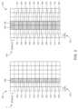
図3は、タイプ1の場合の例示的な時間および周波数構造を示す2つのマップ300、330の例証である。例えば、図3は、1シンボルの場合の例示的なタイプ1DMRSマッピング300と、2シンボルの場合の例示的なタイプ1DMRSマッピング330とを示す。この構造では、2つのWTRUについてのDMRS、すなわちWTRU1についてのDMRSとWTRU2についてのDMRSが、周波数においてインタリーブされてよい。シンボル数に応じて、2シンボルの場合のマッピング330に示されるように同じ構造が時間において繰り返されて、よりよいチャネル推定が達成され得る。実施形態では、WTRU1についてのDMRSとWTRU2についてのDMRSとは、図示のように周波数において、または別法として若しくはそれと組み合わせて時間において、相互と直交してよい。3 illustrates two
例示的なマップ300では、DMRS306~328が、時間においてシンボル302にマッピングされ、周波数においてサブキャリア304にマッピングされる。この例では、WTRU1についてのDMRS308、312、316、320、324、および328と、WTRU2についてのDMRS306、310、314、318、322、および326とが、第3のシンボルの各サブキャリア上で交互にされる。DMRS306、310、314、318、322、および326は、WTRU2によって送信される。DMRS308、312、316、320、324、および328は、WTRU1によって送信される。In the
例示的なマップ330では、DMRSはまた、時間においてシンボル332にマッピングされ、周波数においてサブキャリア334にマッピングされる。この例では、WTRU1およびWTRU2についてのDMRSは、第3のシンボルおよび第4のシンボルの各サブキャリア上で交互にされる。DMRS336、338、344、346、352、354、360、362、368、370、376、および378は、WTRU2によって送信される。DMRS340、342、348、350、356、358、364、366、372、374、380、および382は、WTRU1によって送信される。In the
いくつかの実装形態では、DMRSのシーケンスは、直交位相シフトキーイング(QPSK)変調を用いて周波数領域において決定される。例えば、表1は、長さ6(すなわち、シーケンス長が6)のDMRSのシーケンスを定義し、ここで、In some implementations, the sequence of DMRS is determined in the frequency domain using quadrature phase shift keying (QPSK) modulation. For example, Table 1 defines a sequence of DMRS of length 6 (i.e., sequence length is 6), where:

は、シーケンスインデックスuに対する変調操作であり、φu(n)は、u番目のシーケンスのn番目の要素である。 is the modulation operation on sequence index u, and φu (n) is the n-th element of the u-th sequence.

実施形態では、変調されたシーケンスは、サブキャリアに直接にマッピングされる。これらのシーケンスのPAPR/CM性能は、DFT拡散OFDMデータチャネルに最適化されず、π/2-BPSK DFT-拡散OFDMを伴うデータのPAPRよりも高いPAPRを引き起こし得ることに留意されたい。In an embodiment, the modulated sequences are directly mapped to the subcarriers. Note that the PAPR/CM performance of these sequences is not optimized for the DFT-spread OFDM data channel and may result in a higher PAPR than that of data with π/2-BPSK DFT-spread OFDM.
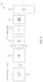
図4は、図3に示されたタイプ1マッピングに適合するDMRSのための例示的な送信機400を示すブロック図である。この例では、シーケンスインデックスu404に基づいてシーケンスセット402からシーケンスが決定されてよく、選ばれたシーケンスは、変調ブロック中で変調タイプを用いて変調される(406)。タイプ1マッピングを可能にするには、得られた出力が2回繰り返され、w1408およびw2410が乗算される。ここで、一方のWTRUについてはw1=w2であり、他方のWTRUについてはw1=-w2である。次いで、シーケンスは、DFT-s-OFDM412中のブロックによってFDSS414を用いて処理され、IDFT416が計算され、得られたベクトルは送信されてよい。 Figure 4 is a block diagram illustrating an
いくつかの例では、セルラーネットワーク中でよい性能を達成するために、図4のシーケンスセットは、低いPAPRと、低いCMと、他のDMRS信号との低い相互相関と、チャネルを推定するためのより大きいゼロ自己相関ゾーンと、よりよいBLER性能を達成するためおよびスペクトル要件に適合するための高い周波数平坦性とを伴う信号に至ることができる。本明細書では、いくつかの例示的なシーケンスが提供される。In some examples, to achieve good performance in cellular networks, the sequence set of FIG. 4 can lead to signals with low PAPR, low CM, low cross-correlation with other DMRS signals, larger zero autocorrelation zones for estimating the channel, and high frequency flatness to achieve better BLER performance and meet spectral requirements. Some example sequences are provided herein.
表2は、タイプ1マッピングのDFT-s-OFDMの場合の8-PSK変調を伴う長さ6について定義され得る例示的なシーケンスセットを示す。Table 2 shows an example set of sequences that can be defined for length 6 with 8-PSK modulation for DFT-s-OFDM with

この例では、変調シンボルは下式を用いて生成される。In this example, the modulation symbols are generated using the following formula:

表3は、タイプ1マッピングのDFT-s-OFDMの場合のπ/2-BPSK変調を伴う長さ12について定義され得る例示的なシーケンスセットを示す。Table 3 shows an example set of sequences that can be defined for length 12 with π/2-BPSK modulation for DFT-s-OFDM with

この例では、変調シンボルは下式を用いて生成される。In this example, the modulation symbols are generated using the following formula:

表4は、タイプ1マッピングのDFT-s-OFDMの場合のπ/2-BPSK変調を伴う長さ18について定義され得る例示的なシーケンスセットを示す。Table 4 shows an example set of sequences that can be defined for length 18 with π/2-BPSK modulation for DFT-s-OFDM with

この例では、変調シンボルは下式を用いて生成される。In this example, the modulation symbols are generated using the following formula:

表5は、タイプ1マッピングのDFT-s-OFDMの場合のπ/2-BPSK変調を伴う長さ24について定義され得る例示的なシーケンスセットを示す。Table 5 shows an example set of sequences that can be defined for length 24 with π/2-BPSK modulation for DFT-s-OFDM with

変調シンボルは下式を用いて生成される。The modulation symbols are generated using the following formula:

いくつかの実装形態では、例えば、FDSSを伴うpi/2BPSK DFT-拡散OFDMの場合のDMRSについてセルラーネットワーク中でよい性能を達成するために、シーケンスセットは、以下のメトリックのうちの1つまたは複数(または全て)を最小化するように構成される。すなわち、メトリック1[dB]:FDSSを伴うPAPR;メトリック2[dB]:FDSSを伴うCM;メトリック3:全てのラグについての時間における周期自己相関(周波数変動を測定する);メトリック4:{-1,1}ラグについての時間における周期自己相関(チャネル推定品質について{-1,1}ラグでゼロ自己相関ゾーンがある場合に測定する);メトリック5:{-2,-1,1,2}ラグについての時間における周期自己相関(チャネル推定品質について{-2,-1,1,2}ラグでゼロ自己相関ゾーンがある場合に測定する);メトリック6:{-3,-2,-1,1,2,3}ラグについての時間における周期自己相関(チャネル推定品質について{-3,-2,-1,1,2,3}ラグでゼロ自己相関ゾーンがある場合に測定する);およびメトリック7:別のDMRS信号との最大ピーク相互相関(セル間干渉の測定)である。In some implementations, to achieve good performance in cellular networks for DMRS, for example for pi/2BPSK DFT-spread OFDM with FDSS, the sequence set is configured to minimize one or more (or all) of the following metrics: Metric 1 [dB]: PAPR with FDSS; Metric 2 [dB]: CM with FDSS; Metric 3: Cyclic autocorrelation in time for all lags (measures frequency variation); Metric 4: Cyclic autocorrelation in time for {-1,1} lags (measures channel estimation quality if there is a zero autocorrelation zone at {-1,1} lags); Metric 5: Cyclic autocorrelation in time for {-2,-1,1,2} lags (measures channel estimation quality if there is a zero autocorrelation zone at {-2,-1,1,2} lags); Metric 6: Cyclic autocorrelation in time for {-3,-2,-1,1,2,3} lags (measures channel estimation quality if there is a zero autocorrelation zone at {-3,-2,-1,1,2,3} lags); and Metric 7: Maximum peak cross-correlation with another DMRS signal (measures inter-cell interference).
表2、表3、表4および表5で提供されたシーケンスセットについてのメトリックの例示的な分布が、[0.28,1,0.28]のフィルタを用いた例示的なFDSSを考慮することによって示される。表6は、これらの例に対応するメトリックの最大値を示す。Exemplary distributions of metrics for the sequence sets provided in Tables 2, 3, 4, and 5 are shown by considering an example FDSS with a filter of [0.28, 1, 0.28]. Table 6 shows the maximum values of the metrics corresponding to these examples.

いくつかの実装形態では、上記のシーケンスセットは、PAPRおよびCMの点ではうまく機能し得る。しかし、いくつかの実装形態では、これらは、周波数平坦性、相互相関(セル間干渉)、および/または周期自己相関(チャネル推定性能)の点ではよい結果をもたらさないことがある。従って、いくつかの実装形態では、種々の長さについての新しいシーケンスセットが提供される。In some implementations, the above sequence sets may perform well in terms of PAPR and CM. However, in some implementations, they may not perform well in terms of frequency flatness, cross-correlation (inter-cell interference), and/or cyclic autocorrelation (channel estimation performance). Therefore, in some implementations, new sequence sets for various lengths are provided.
いくつかの実装形態では、タイプ1マッピングはまた、図4で提供される構造から変更されてもよく、または別の仕方で、図4で提供される構造とは異なってもよい。例えば、異なるw1およびw2コードブックの場合のシーケンスのプロパティが改変されてよい。いくつかの実装形態では、異なる直交カバーコード(OCC)、例えばw1およびw2が提供されてよい。いくつかの実装形態では、w1およびw2は、シーケンスの各要素を異なる仕方で改変してよい。 In some implementations, the
いくつかの実装形態は、置換ベースのセットを含む。例えば、既存のセット、例えば表2、表3、表4、および表5に関して上述されたセット中のN個のシーケンスを置換することによって、既存のシーケンスが改変されてよい。例えば、長さ6の場合、N={3,4,..13,16}回の置換が表2において行われて、例えば表11で提供されるシーケンスとなり、タイプ1マッピングによるπ/2-BPSK DFT-s-OFDMの場合のDMRSの性能が改善され得る。表7は、この場合の所与のNについての例示的な性能改善を示す。長さ12の場合、N={3,4,..13,14}回の置換が表3において行われて、例えば表12で提供されるシーケンスとなり、タイプ1マッピングによるπ/2-BPSK DFT-s-OFDMの場合のDMRSの性能が改善され得る。表8は、この場合の所与のNについての例示的な性能改善を示す。長さ18の場合、N={3,4,..13,18}回の置換が表4において行われて、例えば表13で提供されるシーケンスとなり、タイプ1マッピングによるπ/2-BPSK DFT-s-OFDMの場合のDMRSの性能が改善され得る。表9は、この場合の所与のNについての例示的な性能改善を示す。長さ24の場合、N={3,4,..13,18}回の置換が表5において行われて、例えば表14で提供されるシーケンスとなり、タイプ1マッピングによるπ/2-BPSK DFT-s-OFDMの場合のDMRSの性能が改善され得る。表10は、この場合の所与のNについての例示的な性能改善を示す。Some implementations include permutation-based sets. For example, existing sequences may be modified by permuting N sequences in the existing sets, e.g., the sets described above with respect to Tables 2, 3, 4, and 5. For example, for length 6, N={3, 4, . . 13, 16} permutations may be made in Table 2, e.g., to result in sequences provided in Table 11, to improve the performance of DMRS for π/2-BPSK DFT-s-OFDM with
いくつかの実装形態では、セット中の最後のシーケンスについてのインデックスは、例えば行方向の並べ替えを使用して並べ替えられてよい。いくつかの実装形態では、シーケンスの要素の順序は反転されてよい。いくつかの実装形態では、変調されたシーケンスは、反転および/または接合されてよい。いくつかの実装形態では、これらの操作は、シーケンスセットのプロパティを変更しない。In some implementations, the index for the last sequence in the set may be sorted, for example using a row-wise sort. In some implementations, the order of the elements of the sequence may be reversed. In some implementations, the modulated sequence may be inverted and/or spliced. In some implementations, these operations do not change the properties of the sequence set.


表11は、長さ6の場合の置換ベースのセットについての新しいシーケンスを示す(変調:8-PSK)。Table 11 shows the new sequences for the permutation-based set for length 6 (modulation: 8-PSK).


いくつかの実装形態では、例えば、シーケンス長が6である場合、表11aで提供される値のうちの少なくとも1つが、位相パラメータφ(n)の値として使用されてよい。In some implementations, for example when the sequence length is 6, at least one of the values provided in Table 11a may be used as the value of the phase parameter φ(n).

以下では、長さNのシーケンスの反転バージョンは、同じシーケンスと見なされてよい。例えば、シーケンスφ(0),...,φ(N-1)とその反転バージョンφ(N-1),...,φ(0)とは、同じシーケンスと見なされてよい。In the following, the inverted versions of a sequence of length N may be considered to be the same sequence. For example, the sequence φ(0),...,φ(N-1) and its inverted version φ(N-1),...,φ(0) may be considered to be the same sequence.
表12は、長さ12の場合の置換ベースのセットについての新しいシーケンスを示す(変調:π/2-BPSK)。Table 12 shows the new sequences for the permutation base set for length 12 (modulation: π/2-BPSK).


いくつかの実装形態では、例えば、シーケンス長が12の場合、表12aで提供される値のうちの少なくとも1つが、位相パラメータφu(n)の値として使用されてよい。 In some implementations, for example when the sequence length is 12, at least one of the values provided in Table 12a may be used as the value of the phase parameter φu (n).

表13は、長さ18の場合の置換ベースのセットについての新しいシーケンスを示す(変調:π/2-BPSK)。Table 13 shows the new sequences for the permutation base set for length 18 (modulation: π/2-BPSK).


いくつかの実装形態では、例えば、シーケンス長が18の場合、表13aで提供される値のうちの少なくとも1つが、位相パラメータφu(n)の値として使用されてよい。 In some implementations, for example when the sequence length is 18, at least one of the values provided in Table 13a may be used as the value of the phase parameter φu (n).

表14は、長さ24の場合の置換ベースのセットについての新しいシーケンスを示す(変調:π/2-BPSK)。Table 14 shows the new sequences for the permutation base set for length 24 (modulation: π/2-BPSK).


いくつかの実装形態では、例えば、シーケンス長が24の場合、表14aで提供される値のうちの少なくとも1つが、位相パラメータφu(n)の値として使用されてよい。 In some implementations, for example when the sequence length is 24, at least one of the values provided in Table 14a may be used as the value of the phase parameter φu (n).

いくつかの実装形態は、新しいシーケンスセットを含む。表16、表17、表18、表19、表20、表21、表22、表23、および表24は、それぞれ、QPSKを伴う長さ6の場合のDMRSシーケンス、8-PSKを伴う長さ6の場合のDMRSシーケンス、12-PSKを伴う長さ6の場合のDMRSシーケンス、pi/2-BPSKを伴う長さ12の場合のDMRSシーケンス、pi/2-BPSKを伴う長さ18の場合のDMRSシーケンス、およびpi/2-BPSKを伴う長さ24の場合のDMRSシーケンスとして使用されてよい。Some implementations include new sequence sets. Tables 16, 17, 18, 19, 20, 21, 22, 23, and 24 may be used as DMRS sequences for length 6 with QPSK, DMRS sequences for length 6 with 8-PSK, DMRS sequences for length 6 with 12-PSK, DMRS sequences for length 12 with pi/2-BPSK, DMRS sequences for length 18 with pi/2-BPSK, and DMRS sequences for length 24 with pi/2-BPSK, respectively.
いくつかの例では、以下の表で提供される値のうちの少なくとも1つが、位相パラメータφ(n)の値として使用されてよい。いくつかの例では、周波数における対応するシーケンスの位相変調されたまたは回転されたバージョンが利用されてよい。シーケンスセットは、例えば、図4および図5で提供されるようにタイプ1マッピングの場合のOCCまたは周波数シフティングベースのユーザ多重化方法を用いて利用されてよい。In some examples, at least one of the values provided in the table below may be used as the value of the phase parameter φ(n). In some examples, a phase modulated or rotated version of the corresponding sequence in frequency may be utilized. The sequence set may be utilized, for example, with OCC or frequency shifting based user multiplexing methods for
表15は、例示的な新しいシーケンスセットの例示的な性能を示す。Table 15 shows exemplary performance of an exemplary new sequence set.

いくつかの実装形態では、セット中の最後のシーケンスについてのインデックスは、例えば行方向の並べ替えに基づいて並べ替えられてよい。いくつかの実装形態では、シーケンスの要素の順序は反転されてよい。いくつかの実装形態では、変調されたシーケンスは、反転および/または接合されてよい。いくつかの実装形態では、これらの操作は、シーケンスセットのプロパティを変更しない。In some implementations, the index for the last sequence in the set may be reordered, for example based on a row-wise reordering. In some implementations, the order of the elements of the sequence may be reversed. In some implementations, the modulated sequence may be inverted and/or spliced. In some implementations, these operations do not change the properties of the sequence set.
いくつかの例では、シーケンス長が6であって、π/2-BPSKの変調を有し、自己相関が優先される場合、例えば、シーケンスが、非常によい自己相関を有し、許容可能な相互相関プロパティを伴って閾値自己相関よりも高く、かつ/または閾値相互相関よりも高い場合は、以下の表で提供される値のうちの少なくとも1つが、位相パラメータφ(n)の値として使用される。In some examples, when the sequence length is 6 and has a modulation of π/2-BPSK, and autocorrelation is preferred, e.g., the sequence has very good autocorrelation and is higher than the threshold autocorrelation and/or higher than the threshold cross-correlation with acceptable cross-correlation properties, at least one of the values provided in the table below is used as the value of the phase parameter φ(n).

変調シンボルは下式を用いて生成される。The modulation symbols are generated using the following formula:

いくつかの例では、シーケンス長が6である場合(変調:π/2-BPSK-相互相関が先-すなわち相互相関が優先される。例えば、シーケンスが非常によい相互相関(例えば、閾値相互相関よりも高い)を有し、許容可能な自己相関プロパティ(例えば、閾値自己相関よりも高い)を伴う)は、以下の表で提供される値のうちの少なくとも1つが、位相パラメータφ(n)の値として使用される。In some examples, when the sequence length is 6 (modulation: π/2-BPSK - cross-correlation first - i.e. cross-correlation is prioritized, e.g., the sequence has very good cross-correlation (e.g., higher than threshold cross-correlation) with acceptable auto-correlation properties (e.g., higher than threshold auto-correlation), at least one of the values provided in the table below is used as the value of the phase parameter φ(n).

変調シンボルは下式を用いて生成される。The modulation symbols are generated using the following formula:

いくつかの例では、シーケンス長が6であって、QPSK変調を使用し、自己相関が優先される場合、例えば、シーケンスが、許容可能な相互相関プロパティ(例えば、閾値相互相関よりも高い)を伴って、閾値自己相関よりも高い非常によい自己相関を有する場合は、以下の表で提供される値のうちの少なくとも1つが、位相パラメータφ(n)の値として使用される。In some examples, when the sequence length is 6, QPSK modulation is used, and autocorrelation is preferred, e.g., the sequence has very good autocorrelation, higher than the threshold autocorrelation, with acceptable cross-correlation properties (e.g., higher than the threshold cross-correlation), at least one of the values provided in the following table is used as the value of the phase parameter φ(n):

変調シンボルは下式を用いて生成される。
su(n)=ejφ(n)π/4. The modulation symbols are generated using the following equation:
su (n)=ejφ(n)π/4 .
いくつかの例では、シーケンス長が6であって、QPSK変調を有し、相互相関が優先される場合、例えば、シーケンスが、許容可能な自己相関プロパティ(例えば、閾値自己相関よりも高い)を伴って、閾値相互相関よりも高い非常によい相互相関を有する場合は、以下の表で提供される値のうちの少なくとも1つが、位相パラメータφ(n)の値として使用される。In some examples, when the sequence length is 6, has QPSK modulation, and cross-correlation is preferred, e.g., the sequence has very good cross-correlation, higher than the threshold cross-correlation, with acceptable autocorrelation properties (e.g., higher than the threshold autocorrelation), at least one of the values provided in the table below is used as the value of the phase parameter φ(n).

変調シンボルは下式を用いて生成される。
su(n)=ejφ(n)π/4. The modulation symbols are generated using the following equation:
su (n)=ejφ(n)π/4 .
いくつかの例では、シーケンス長が6(変調:8-PSK)の場合は、表20で提供される値のうちの少なくとも1つが、位相パラメータφ(n)の値として使用される。In some examples, when the sequence length is 6 (modulation: 8-PSK), at least one of the values provided in Table 20 is used as the value of the phase parameter φ(n).

この例では、変調シンボルは下式を用いて生成される。
su(n)=ejφ(n)π/8. In this example, the modulation symbols are generated using the following equation:
su (n)=ejφ(n)π/8 .
いくつかの例では、シーケンス長が6(変調:12-PSK)の場合は、表21で提供される値のうちの少なくとも1つが、位相パラメータφu(n)の値として使用される。 In some examples, when the sequence length is 6 (modulation: 12-PSK), at least one of the values provided in Table 21 is used as the value of the phase parameter φu (n).

いくつかの例では、シーケンス長が12(変調:π/2-BPSK)である場合は、表22で提供される値のうちの少なくとも1つが、位相パラメータφu(n)の値として使用される。 In some examples, when the sequence length is 12 (modulation: π/2-BPSK), at least one of the values provided in Table 22 is used as the value of the phase parameter φu (n).

この例では、変調シンボルは下式を用いて生成される。In this example, the modulation symbols are generated using the following formula:

いくつかの例では、表22中のシーケンスインデックス9、10、19、および11を含むシーケンスセットからの1つまたは複数のシーケンスが特に、DMRSとして利用されて他のシーケンスと結合されてよい。In some examples, one or more sequences from the sequence set including sequence indexes 9, 10, 19, and 11 in Table 22 may be specifically utilized as a DMRS and combined with other sequences.
いくつかの例では、表22中のシーケンスインデックス9、10、19、11、27、28、4、5を含むシーケンスセットからの1つまたは複数のシーケンスが特に、DMRSとして利用されて他のシーケンスと結合されてよい。In some examples, one or more sequences from the sequence set including
いくつかの例では、シーケンス長が18(変調:π/2-BPSK)である場合は、表23で提供される値のうちの少なくとも1つが、位相パラメータφu(n)の値として使用される。 In some examples, when the sequence length is 18 (modulation: π/2-BPSK), at least one of the values provided in Table 23 is used as the value of the phase parameter φu (n).

この例では、変調シンボルは下式を用いて生成される。In this example, the modulation symbols are generated using the following formula:

いくつかの例では、表23中のシーケンスインデックス18、22、3、8、14、2、7、および29を含むシーケンスセットからの1つまたは複数のシーケンスが特に、DMRSとして利用されて他のシーケンスと結合されてよい。In some examples, one or more sequences from the sequence set including
いくつかの例では、表23中のシーケンスインデックス18、22、3、および8を含むシーケンスセットからの1つまたは複数のシーケンスが特に、DMRSとして利用されて他のシーケンスと結合されてよい。In some examples, one or more sequences from the sequence set including sequence indexes 18, 22, 3, and 8 in Table 23 may be specifically utilized as a DMRS and combined with other sequences.
いくつかの例では、シーケンス長が24(変調:π/2-BPSK)である場合は、表24で提供される値のうちの少なくとも1つが、位相パラメータφu(n)の値として使用される。 In some examples, when the sequence length is 24 (modulation: π/2-BPSK), at least one of the values provided in Table 24 is used as the value of the phase parameter φu (n).

この例では、変調シンボルは下式を用いて生成される。In this example, the modulation symbols are generated using the following formula:

いくつかの例では、表24中のシーケンスインデックス29、6、27、28、23、11、22、および12を含むシーケンスセットからの1つまたは複数のシーケンスが特に、DMRSとして利用されて他のシーケンスと結合されてよい。In some examples, one or more sequences from the sequence set including sequence indexes 29, 6, 27, 28, 23, 11, 22, and 12 in Table 24 may be specifically utilized as a DMRS and combined with other sequences.
いくつかの例では、表24中のシーケンスインデックス29、6、27、および28を含むシーケンスセットからの1つまたは複数のシーケンスが特に、DMRSとして利用されて他のシーケンスと結合されてよい。In some examples, one or more sequences from the sequence set including sequence indexes 29, 6, 27, and 28 in Table 24 may be specifically utilized as a DMRS and combined with other sequences.
いくつかの実装形態は、ユーザ多重化を含む。Some implementations include user multiplexing.
図5は、シーケンスセットのプロパティを失うことなくDMRS信号を生成するための例示的な送信機500を含む、ユーザ多重化の例を示すブロック図である。この例では、第1のブロックで、シーケンスインデックスu504に基づいてシーケンスセット502からシーケンスが決定されてよい。第2のブロックで、選ばれたシーケンスは、変調タイプ、例えばπ/2-BPSKを用いて変調されてよい(506)。得られた出力は、2回繰り返されてよい(508、510)。その後、第3のブロックで、繰り返されたシーケンスはDFTプリコーダによってプリコーディングされてよく(512)、第4のブロックで、DFTの出力は、WTRUインデックス516、OCCインデックス、または他のインデックスによってシフトされて(514)、タイプ1マッピングが可能にされてよい。次いで、第5のブロックで、シーケンスはFDSSを用いて処理される(518)。第6のブロックでIDFT520が計算され、得られたベクトルは送信されてよい。いくつかの実装形態では、この手法は、シーケンスセットのプロパティ、例えば、相互相関プロパティ、PAPR、CM、および/または自己相関プロパティを変更しない。いくつかの例では、シーケンスは、DFT操作の前に循環的にシフトされて、複数の直交DMRSポートが可能にされてよい。いくつかの例では、位相回転または変調操作、すなわち5 is a block diagram illustrating an example of user multiplexing including an

が行われてよく、ここで、n、k∈{0,1,...,M-1}であり、sは、IDFT操作の前の繰り返されるシーケンスまたは繰り返されたシーケンスであってよい。いくつかの例では、同じ操作を使用して、周波数においてシーケンスがシフトされてよい。where n, k∈{0, 1, ..., M-1} and s may be the repeated sequence before the IDFT operation or the repeated sequence. In some examples, the same operation may be used to shift the sequence in frequency.
上記では特徴および要素が特定の組合せで記述されているが、各特徴または要素は、単独で使用されることも可能であり、または他の特徴および要素との任意の組合せで使用され得ることを、当業者は理解するであろう。加えて、本明細書に記載の方法は、コンピュータまたはプロセッサによって実行されるようにコンピュータ可読媒体に組み込まれたコンピュータプログラム、ソフトウェア、またはファームウェアにおいて実装されてよい。コンピュータ可読媒体の例は、電子信号(有線および/または無線接続を介して伝送される)、並びにコンピュータ可読記憶媒体を含む。コンピュータ可読記憶媒体の例は、以下のものに限定されないが、読取専用メモリ(ROM)、ランダムアクセスメモリ(RAM)、レジスタ、キャッシュメモリ、半導体メモリデバイス、磁気媒体(内蔵ハードディスクおよび取外し可能ディスクなど)、光磁気媒体、並びに光学媒体(CD-ROMディスクおよびデジタル多用途ディスク(DVD)など)を含む。ソフトウェアと連携したプロセッサが使用されて、WTRU、UE、端末、基地局、RNC、または任意のホストコンピュータ中で使用される無線周波数送受信機が実装されてよい。Although features and elements are described above in specific combinations, one skilled in the art will understand that each feature or element can be used alone or in any combination with other features and elements. In addition, the methods described herein may be implemented in a computer program, software, or firmware embodied in a computer-readable medium for execution by a computer or processor. Examples of computer-readable media include electronic signals (transmitted over wired and/or wireless connections) and computer-readable storage media. Examples of computer-readable storage media include, but are not limited to, read-only memory (ROM), random access memory (RAM), registers, cache memory, semiconductor memory devices, magnetic media (such as internal hard disks and removable disks), magneto-optical media, and optical media (such as CD-ROM disks and digital versatile disks (DVDs)). A processor in conjunction with software may be used to implement a radio frequency transceiver for use in a WTRU, UE, terminal, base station, RNC, or any host computer.
Claims (5)
Translated fromJapanese000000110110、000001000111および000001110111を含むシーケンスのセットからシーケンスを決定するように構成された回路と、
前記決定されたシーケンスから導出された復調基準信号(DMRS)を送信するように構成された送信機と
を備えたWTRU。 1. A wireless transmit/receive unit (WTRU), comprising:
a circuit configured to determine a sequence from a set of sequences including: 000000110110, 000001000111, and 000001110111;
a transmitter configured to transmit a demodulation reference signal (DMRS) derived from the determined sequence.
Applications Claiming Priority (7)
| Application Number | Priority Date | Filing Date | Title |
|---|---|---|---|
| US201962787647P | 2019-01-02 | 2019-01-02 | |
| US62/787,647 | 2019-01-02 | ||
| US201962792227P | 2019-01-14 | 2019-01-14 | |
| US62/792,227 | 2019-01-14 | ||
| US201962793827P | 2019-01-17 | 2019-01-17 | |
| US62/793,827 | 2019-01-17 | ||
| PCT/US2019/069101WO2020142513A1 (en) | 2019-01-02 | 2019-12-31 | Low papr dmrs and low inter-cell interference for dft-spread ofdm |
Publications (2)
| Publication Number | Publication Date |
|---|---|
| JP2022515903A JP2022515903A (en) | 2022-02-22 |
| JP7556860B2true JP7556860B2 (en) | 2024-09-26 |
Family
ID=69326767
Family Applications (1)
| Application Number | Title | Priority Date | Filing Date |
|---|---|---|---|
| JP2021538693AActiveJP7556860B2 (en) | 2019-01-02 | 2019-12-31 | Low PAPR DMRS and low inter-cell interference for DFT-spread OFDM |
Country Status (6)
| Country | Link |
|---|---|
| US (2) | US12132592B2 (en) |
| EP (1) | EP3906626A1 (en) |
| JP (1) | JP7556860B2 (en) |
| CN (2) | CN113475018B (en) |
| MX (1) | MX2021008046A (en) |
| WO (1) | WO2020142513A1 (en) |
Families Citing this family (3)
| Publication number | Priority date | Publication date | Assignee | Title |
|---|---|---|---|---|
| CN111770041B (en)* | 2019-03-30 | 2023-02-03 | 华为技术有限公司 | Data compression method and device |
| US11910217B2 (en)* | 2020-05-07 | 2024-02-20 | Qualcomm Incorporated | Demodulation reference signal based self-interference measurement |
| US20250132965A1 (en)* | 2021-08-10 | 2025-04-24 | Ntt Docomo, Inc. | Terminal device and processing method |
Citations (1)
| Publication number | Priority date | Publication date | Assignee | Title |
|---|---|---|---|---|
| US20180309552A1 (en) | 2017-04-25 | 2018-10-25 | Qualcomm Incorporated | Transmitting uplink control information (uci) |
Family Cites Families (8)
| Publication number | Priority date | Publication date | Assignee | Title |
|---|---|---|---|---|
| KR100940730B1 (en) | 2007-09-07 | 2010-02-04 | 엘지전자 주식회사 | Method of generating reference signal in wireless communication system |
| US10560301B2 (en)* | 2015-10-16 | 2020-02-11 | Intel IP Corporation | Apparatuses for DMRS design or processing for guard interval or zero tail DFT spread OFDM systems |
| CN109804579A (en)* | 2016-09-28 | 2019-05-24 | Idac控股公司 | Common control channel and reference symbol for the transmission of more Wave datas |
| EP3402100B1 (en)* | 2017-02-06 | 2021-03-31 | LG Electronics Inc. -1- | Method for transmitting and receiving signals between terminal and base station in wireless communication system, and apparatus for supporting same |
| EP3791688B1 (en)* | 2018-05-10 | 2022-11-23 | IPLA Holdings Inc. | Small data transmission with non-orthogonal multiple access |
| JP7383008B2 (en)* | 2018-08-09 | 2023-11-17 | インターデイジタル パテント ホールディングス インコーポレイテッド | Beamforming and grouping for NR V2X |
| WO2020089931A1 (en)* | 2018-10-28 | 2020-05-07 | Indian Institute Of Technology Hyderabad | Method and system for generating a transmit waveform for reference sequences |
| KR102617897B1 (en)* | 2019-02-15 | 2023-12-26 | 삼성전자주식회사 | Method and apparatus for transmitting and receiving uplink reference signal in wireless communication systems |
- 2019
- 2019-12-31CNCN201980092054.6Apatent/CN113475018B/enactiveActive
- 2019-12-31MXMX2021008046Apatent/MX2021008046A/enunknown
- 2019-12-31WOPCT/US2019/069101patent/WO2020142513A1/ennot_activeCeased
- 2019-12-31CNCN202411516726.0Apatent/CN119254378A/enactivePending
- 2019-12-31EPEP19843060.5Apatent/EP3906626A1/enactivePending
- 2019-12-31JPJP2021538693Apatent/JP7556860B2/enactiveActive
- 2019-12-31USUS17/419,322patent/US12132592B2/enactiveActive
- 2024
- 2024-10-03USUS18/905,549patent/US20250030587A1/enactivePending
Patent Citations (1)
| Publication number | Priority date | Publication date | Assignee | Title |
|---|---|---|---|---|
| US20180309552A1 (en) | 2017-04-25 | 2018-10-25 | Qualcomm Incorporated | Transmitting uplink control information (uci) |
Non-Patent Citations (2)
| Title |
|---|
| Ericsson,Feature lead summary #3 of low PAPR RS,3GPP TSG RAN WG1 #95 R1-1814109,2018年11月19日,pp.1-9,<URL:http://www.3gpp.org/ftp/tsg_ran/WG1_RL1/TSGR1_95/Docs/R1-1814109.zip><R1-1814109 Feature lead summary of low PAPR.docx> |
| InterDigital, Inc.,On Low PAPR RS,3GPP TSG RAN WG1 Ad-Hoc 1901 R1-1900811,2019年01月12日,pp.1-11,<URL:http://www.3gpp.org/ftp/tsg_ran/WG1_RL1/TSGR1_AH/NR_AH_1901/Docs/R1-1900811.zip><R1-1900811 Low PAPR RS_final.docx> |
Also Published As
| Publication number | Publication date |
|---|---|
| WO2020142513A1 (en) | 2020-07-09 |
| US12132592B2 (en) | 2024-10-29 |
| MX2021008046A (en) | 2021-09-08 |
| JP2022515903A (en) | 2022-02-22 |
| CN113475018B (en) | 2024-10-18 |
| EP3906626A1 (en) | 2021-11-10 |
| US20250030587A1 (en) | 2025-01-23 |
| US20220094583A1 (en) | 2022-03-24 |
| CN113475018A (en) | 2021-10-01 |
| CN119254378A (en) | 2025-01-03 |
Similar Documents
| Publication | Publication Date | Title |
|---|---|---|
| JP7583138B2 (en) | Phase tracking reference signal transmission | |
| US11637728B2 (en) | Waveform coding with modulation for single-user and multiple-user transmissions | |
| US12262383B2 (en) | Control channel for new radio | |
| US20240414043A1 (en) | Coexistence of 802.11 protocols in wlan | |
| US20200036470A1 (en) | Common control channel and reference symbol for multiple waveform data transmission | |
| JP2023011680A (en) | Method for Flexible Reference Signal Transmission Using Single-Carrier Frequency Division Multiple Access (SC-FDMA) and OFDMA | |
| TWI807617B (en) | Method and apparatus for modulation of millimeter waves and preamble design | |
| WO2019139983A1 (en) | SHORT PHYSICAL UPLINK CONTROL CHANNEL (sPUCCH) STRUCTURE | |
| US20250030587A1 (en) | Low papr dmrs and low inter-cell interference for dft-spread ofdm | |
| CN110603790A (en) | Transmit diversity for uplink control channels using discrete Fourier transform spread orthogonal frequency division multiplexing (DFT-S-OFDM) waveforms | |
| WO2019035961A1 (en) | Encoding data with golay sequences | |
| US20240023103A1 (en) | Physical uplink control channel transmission | |
| WO2024206424A1 (en) | Enabling rate matching for retransmission with tone reservation | |
| WO2024173172A1 (en) | Mcs indication for second codeword | |
| WO2024044451A1 (en) | Adaptive and distributed reference signal insertion in discreet fourier transform-spread-orthogonal frequency division multiplexing (dft-s-ofdm) signals |
Legal Events
| Date | Code | Title | Description |
|---|---|---|---|
| A521 | Request for written amendment filed | Free format text:JAPANESE INTERMEDIATE CODE: A523 Effective date:20210901 | |
| RD02 | Notification of acceptance of power of attorney | Free format text:JAPANESE INTERMEDIATE CODE: A7422 Effective date:20210806 | |
| RD04 | Notification of resignation of power of attorney | Free format text:JAPANESE INTERMEDIATE CODE: A7424 Effective date:20211029 | |
| A621 | Written request for application examination | Free format text:JAPANESE INTERMEDIATE CODE: A621 Effective date:20230104 | |
| A711 | Notification of change in applicant | Free format text:JAPANESE INTERMEDIATE CODE: A711 Effective date:20231010 | |
| A977 | Report on retrieval | Free format text:JAPANESE INTERMEDIATE CODE: A971007 Effective date:20240110 | |
| A131 | Notification of reasons for refusal | Free format text:JAPANESE INTERMEDIATE CODE: A131 Effective date:20240130 | |
| A521 | Request for written amendment filed | Free format text:JAPANESE INTERMEDIATE CODE: A523 Effective date:20240412 | |
| TRDD | Decision of grant or rejection written | ||
| A01 | Written decision to grant a patent or to grant a registration (utility model) | Free format text:JAPANESE INTERMEDIATE CODE: A01 Effective date:20240716 | |
| A601 | Written request for extension of time | Free format text:JAPANESE INTERMEDIATE CODE: A601 Effective date:20240815 | |
| A61 | First payment of annual fees (during grant procedure) | Free format text:JAPANESE INTERMEDIATE CODE: A61 Effective date:20240912 | |
| R150 | Certificate of patent or registration of utility model | Ref document number:7556860 Country of ref document:JP Free format text:JAPANESE INTERMEDIATE CODE: R150 |