JP7554206B2 - Non-breathable body fluid sample optimization device and system - Google Patents
Non-breathable body fluid sample optimization device and systemDownload PDFInfo
- Publication number
- JP7554206B2 JP7554206B2JP2021558648AJP2021558648AJP7554206B2JP 7554206 B2JP7554206 B2JP 7554206B2JP 2021558648 AJP2021558648 AJP 2021558648AJP 2021558648 AJP2021558648 AJP 2021558648AJP 7554206 B2JP7554206 B2JP 7554206B2
- Authority
- JP
- Japan
- Prior art keywords
- fluid
- outlet
- sample
- inlet
- fluid sample
- Prior art date
- Legal status (The legal status is an assumption and is not a legal conclusion. Google has not performed a legal analysis and makes no representation as to the accuracy of the status listed.)
- Active
Links
Images


Classifications
- G—PHYSICS
- G01—MEASURING; TESTING
- G01N—INVESTIGATING OR ANALYSING MATERIALS BY DETERMINING THEIR CHEMICAL OR PHYSICAL PROPERTIES
- G01N1/00—Sampling; Preparing specimens for investigation
- G01N1/02—Devices for withdrawing samples
- G01N1/10—Devices for withdrawing samples in the liquid or fluent state
- A—HUMAN NECESSITIES
- A61—MEDICAL OR VETERINARY SCIENCE; HYGIENE
- A61B—DIAGNOSIS; SURGERY; IDENTIFICATION
- A61B5/00—Measuring for diagnostic purposes; Identification of persons
- A61B5/15—Devices for taking samples of blood
- A61B5/150007—Details
- A61B5/150015—Source of blood
- A61B5/15003—Source of blood for venous or arterial blood
- A—HUMAN NECESSITIES
- A61—MEDICAL OR VETERINARY SCIENCE; HYGIENE
- A61B—DIAGNOSIS; SURGERY; IDENTIFICATION
- A61B5/00—Measuring for diagnostic purposes; Identification of persons
- A61B5/15—Devices for taking samples of blood
- A61B5/150007—Details
- A61B5/150053—Details for enhanced collection of blood or interstitial fluid at the sample site, e.g. by applying compression, heat, vibration, ultrasound, suction or vacuum to tissue; for reduction of pain or discomfort; Skin piercing elements, e.g. blades, needles, lancets or canulas, with adjustable piercing speed
- A61B5/150061—Means for enhancing collection
- A61B5/150099—Means for enhancing collection by negative pressure, other than vacuum extraction into a syringe by pulling on the piston rod or into pre-evacuated tubes
- A—HUMAN NECESSITIES
- A61—MEDICAL OR VETERINARY SCIENCE; HYGIENE
- A61B—DIAGNOSIS; SURGERY; IDENTIFICATION
- A61B5/00—Measuring for diagnostic purposes; Identification of persons
- A61B5/15—Devices for taking samples of blood
- A61B5/150007—Details
- A61B5/150206—Construction or design features not otherwise provided for; manufacturing or production; packages; sterilisation of piercing element, piercing device or sampling device
- A61B5/150213—Venting means
- A—HUMAN NECESSITIES
- A61—MEDICAL OR VETERINARY SCIENCE; HYGIENE
- A61B—DIAGNOSIS; SURGERY; IDENTIFICATION
- A61B5/00—Measuring for diagnostic purposes; Identification of persons
- A61B5/15—Devices for taking samples of blood
- A61B5/150007—Details
- A61B5/150206—Construction or design features not otherwise provided for; manufacturing or production; packages; sterilisation of piercing element, piercing device or sampling device
- A61B5/150251—Collection chamber divided into at least two compartments, e.g. for division of samples
- A—HUMAN NECESSITIES
- A61—MEDICAL OR VETERINARY SCIENCE; HYGIENE
- A61B—DIAGNOSIS; SURGERY; IDENTIFICATION
- A61B5/00—Measuring for diagnostic purposes; Identification of persons
- A61B5/15—Devices for taking samples of blood
- A61B5/150007—Details
- A61B5/150351—Caps, stoppers or lids for sealing or closing a blood collection vessel or container, e.g. a test-tube or syringe barrel
- A—HUMAN NECESSITIES
- A61—MEDICAL OR VETERINARY SCIENCE; HYGIENE
- A61B—DIAGNOSIS; SURGERY; IDENTIFICATION
- A61B5/00—Measuring for diagnostic purposes; Identification of persons
- A61B5/15—Devices for taking samples of blood
- A61B5/150992—Blood sampling from a fluid line external to a patient, such as a catheter line, combined with an infusion line; Blood sampling from indwelling needle sets, e.g. sealable ports, luer couplings or valves
- A—HUMAN NECESSITIES
- A61—MEDICAL OR VETERINARY SCIENCE; HYGIENE
- A61B—DIAGNOSIS; SURGERY; IDENTIFICATION
- A61B5/00—Measuring for diagnostic purposes; Identification of persons
- A61B5/15—Devices for taking samples of blood
- A61B5/153—Devices specially adapted for taking samples of venous or arterial blood, e.g. with syringes
- A61B5/154—Devices using pre-evacuated means
Landscapes
- Health & Medical Sciences (AREA)
- Life Sciences & Earth Sciences (AREA)
- Engineering & Computer Science (AREA)
- General Health & Medical Sciences (AREA)
- Physics & Mathematics (AREA)
- Pathology (AREA)
- Animal Behavior & Ethology (AREA)
- Biomedical Technology (AREA)
- Heart & Thoracic Surgery (AREA)
- Medical Informatics (AREA)
- Molecular Biology (AREA)
- Surgery (AREA)
- Biophysics (AREA)
- Hematology (AREA)
- Public Health (AREA)
- Veterinary Medicine (AREA)
- Manufacturing & Machinery (AREA)
- Dermatology (AREA)
- Pain & Pain Management (AREA)
- Analytical Chemistry (AREA)
- Biochemistry (AREA)
- General Physics & Mathematics (AREA)
- Immunology (AREA)
- Chemical & Material Sciences (AREA)
- Hydrology & Water Resources (AREA)
- Sampling And Sample Adjustment (AREA)
- Measurement Of The Respiration, Hearing Ability, Form, And Blood Characteristics Of Living Organisms (AREA)
Description
Translated fromJapanese 本開示は、一般に、流体サンプルを最適化するための流体サンプル最適化装置及びシステムに関する。
(関連出願の相互参照)
本出願は、2019年4月1日に出願された米国仮出願第62/827,783号の利益を主張する。この出願は、その全体が参照により本明細書に組み込まれる。 The present disclosure relates generally to a fluid sample optimization device and system for optimizing a fluid sample.
CROSS-REFERENCE TO RELATED APPLICATIONS
This application claims the benefit of U.S. Provisional Application No. 62/827,783, filed April 1, 2019, which is incorporated herein by reference in its entirety.
菌血症とは、血液中に微生物が存在することである。一方、敗血症は、発熱、頻脈、頻呼吸及び低血圧等の臨床症状及び徴候がある場合の菌血症である。菌血症と敗血症は高い死亡率と入院の発生率と期間及び関連費用の増加と関連している。多くの菌血症、敗血症、真菌血症及び他の病原体は、カテーテル及び静脈穿刺がこれらの病原体の潜在的キャリアとして汚染源となることで、病院又は他の医療施設内で実際に発生している。Bacteremia is the presence of microorganisms in the blood. Sepsis, on the other hand, is bacteremia with clinical symptoms and signs such as fever, tachycardia, tachypnea, and hypotension. Bacteremia and sepsis are associated with high mortality and increased incidence and duration of hospitalization and associated costs. Many bacteremias, sepsis, fungemias, and other pathogens occur within hospitals or other healthcare facilities due to the contamination of catheters and venipunctures as potential carriers of these pathogens.
血液培養は、患者の血液中の菌血症及び敗血症に関連する微生物病原体を検出するために用いられる標準的な検査である。血液培養という用語は、血液が1つ以上の血液培養ボトル又は容器に接種される場合の、末梢部位又は中心若しくは動脈経路のいずれかからの単一の静脈穿刺を指す。1つのボトルが血液培養と見なされ、2つ以上はセットと見なされる。複数のセットが複数の静脈穿刺から得られてもよく、患者の異なる部位に関連する。Blood culture is the standard test used to detect microbial pathogens associated with bacteremia and sepsis in a patient's blood. The term blood culture refers to a single venipuncture, either from a peripheral site or from a central or arterial route, where blood is inoculated into one or more blood culture bottles or containers. One bottle is considered a blood culture, two or more are considered a set. Multiple sets may be obtained from multiple venipunctures, associated with different sites on the patient.
これらの方法は、敗血症の管理に不可欠な構成要素である微生物同定及び感受性試験の実行を可能にするが、迅速な結果が得られず、耐性病原体に対する感受性が低下するため、改良されたシステム及び補助的な分子又はプロテオミクス試験が開発されている。Although these methods allow for the performance of microbial identification and susceptibility testing, which are essential components in the management of sepsis, they do not provide rapid results and have reduced susceptibility to resistant pathogens, leading to the development of improved systems and complementary molecular or proteomic tests.
血液培養を行うための血液サンプルの収集は、現代の患者ケアの重要な構成要素であり、正確な診断を提供することによって患者の転帰にプラスの影響を与えるか、又は感染症の偽陽性結果を提供し、不必要な抗菌薬療法を延長し、入院期間を延長し、かつ費用を増加させることによって転帰にマイナスの影響を与える可能性がある。Collection of blood samples to perform blood cultures is a critical component of modern patient care and can either positively impact patient outcomes by providing an accurate diagnosis or negatively impact outcomes by providing false-positive results for infection, prolonging unnecessary antibiotic therapy, increasing hospital stays, and increasing costs.
血液培養の収集の結果の1つは汚染である。血液培養汚染は、偽陽性培養結果及び/又は医療関連費用の大幅な増加につながる可能性がある。血液培養による汚染の原因には、不適切な皮膚消毒、不適切な採血チューブ消毒、採血時の最初の血液量の汚染等があり、これらによって結果が歪められ得る。One of the consequences of blood culture collection is contamination. Blood culture contamination can lead to false positive culture results and/or significantly increased healthcare-related costs. Causes of blood culture contamination include improper skin preparation, improper disinfection of blood collection tubes, and contamination of the initial blood volume at the time of collection, which can skew the results.
血液培養収集キットは、一般に、BD、Smith、B.Braunのような会社によって提供される「バタフライ」セット、注入セット、又は他のタイプの静脈穿刺装置、及び好気性と嫌気性の血液培養ボトルからなる。また、試験条件に応じて様々なボトルも利用可能である。これらのボトルは、好気性生物と嫌気性生物の両方の復帰を最適化するように特別に設計されている。従来のキットでは、使用されるボトルは、一般に“Vacutainer”として知られており、これは、血液のような所定量の液体の吸引を容易にするためにチューブ内に真空を生成するように排気される閉鎖部を有する無菌ガラス又はプラスチックチューブから形成された血液収集チューブである。Blood culture collection kits generally consist of a "butterfly" set, infusion set, or other type of venipuncture device provided by companies such as BD, Smith, B. Braun, and aerobic and anaerobic blood culture bottles. A variety of bottles are also available depending on the test conditions. These bottles are specifically designed to optimize the return of both aerobic and anaerobic organisms. In conventional kits, the bottles used are commonly known as "Vacutainers," which are blood collection tubes formed from sterile glass or plastic tubing with a closure that is evacuated to create a vacuum within the tube to facilitate the aspiration of a predetermined amount of liquid, such as blood.
偽陽性の血液培養は、典型的には不十分なサンプリング技術の結果である。これは、必要でないときに抗生物質の使用を引き起こし、病院の費用と患者の不安を増大させる。血液培養が針刺しから皮膚に吸い込まれ、Vacutainerを取り付けて血液サンプルを採取する。汚染は、穿刺部位及びその周囲の皮膚領域の不適切又は不完全な消毒によって生じることがある。それはまた、挿入中の針による皮膚のコアリングから生じることもあり、コアリングされた皮膚細胞及び任意の関連する汚染物質がサンプルに引き込まれる。False positive blood cultures are typically the result of poor sampling technique. This leads to antibiotic use when not necessary, increasing hospital costs and patient anxiety. Blood cultures are drawn from a needle prick into the skin, and a Vacutainer is attached to obtain the blood sample. Contamination can result from improper or incomplete disinfection of the puncture site and surrounding skin area. It can also result from coring of the skin by the needle during insertion, drawing cored skin cells and any associated contaminants into the sample.
皮下注射針を通る血流は層流であるため、皮下注射針に圧力降下が加えられると、流速勾配がフローチューブを横断して生じ得る。血液を強く吸引し、又は非常に細い皮下注射針を使用すると、赤血球からのカリウムの溶解又は放出が起こることで、血液サンプルに異常が生じる可能性がある。Because blood flow through a hypodermic needle is laminar, a flow velocity gradient can develop across the flow tube when a pressure drop is applied across the hypodermic needle. Using a strong blood draw or a very thin hypodermic needle can cause anomalies in the blood sample due to dissolution or release of potassium from red blood cells.
血液培養の汚染率を減少させるために様々な戦略が実施されている。例えば、無菌収集技術に関するスタッフの訓練、汚染率に関するフィードバック、血液培養収集キットの実装等である。皮膚消毒は汚染の量を減らし得るが、皮膚の微生物の20%以上は真皮の奥深くに位置しており、消毒の影響を受けない。ボトル接種前に針を交換することは、汚染率を低下させないが針棒が損傷を被るリスクを増大させるため推奨されない。Various strategies have been implemented to reduce blood culture contamination rates, including training staff on aseptic collection technique, feedback on contamination rates, and implementation of blood culture collection kits. Skin disinfection can reduce the amount of contamination, but more than 20% of microorganisms on the skin are located deep in the dermis and are not affected by disinfection. Changing needles before bottle inoculation is not recommended as it does not reduce contamination rates but increases the risk of needle stick injury.
血液培養汚染を低減するためのいくつかの従来のシステム及び技術は、中心静脈カテーテル、静脈穿刺、及び他の血管アクセスシステムから収集された血液の最初のアリコートを廃棄することを含む。しかしながら、これらのシステムは、ユーザが血管内装置を機械的に操作することを必要とし、又は困難でありかつ一貫して従う機会を減少させる複雑な一連の工程を必要とする。Some conventional systems and techniques for reducing blood culture contamination include discarding the first aliquot of blood collected from central venous catheters, venipunctures, and other vascular access systems. However, these systems require the user to mechanically manipulate an intravascular device or require a complex series of steps that are difficult and reduce the chances of being followed consistently.
この文書は、血液サンプリング又は血液培養収集システムで使用するための非通気性体液サンプル最適化装置及びシステムを記載する。本明細書に記載の実装によれば、装置は、1つの動作モードから別の動作モードへ、又は1つの状態から別の状態へ移動、シフト又は遷移する移動部品、弁、状態遷移スイッチ又はダイバータ、又は他の機構を有さない。This document describes a non-breathable body fluid sample optimization device and system for use in a blood sampling or blood culture collection system. In accordance with the implementations described herein, the device does not have any moving parts, valves, state transition switches or diverters, or other mechanisms that move, shift, or transition from one operating mode to another, or from one state to another.
いくつかの実装では、流体サンプル最適化装置は、入口ポート、出口ポート、及び入口ポートに結合された近位端及び出口ポートに結合された遠位端を有する汚染物質封じ込めリザーバを含む。流体サンプル最適化装置は、汚染物質封じ込めリザーバ内に配置されかつ固定された空気透過性流体抵抗器をさらに含み、空気透過性流体抵抗器は、汚染物質封じ込めリザーバの近位端に向かう前面と、汚染物質封じ込めリザーバの遠位端に向かう背面とを有する。流体サンプル最適化装置は、汚染物質封じ込めリザーバの近位端に近い入口ポートに接続された近位端と、出口ポートに結合された遠位端とを有するサンプル経路をさらに含む。In some implementations, the fluid sample optimization device includes an inlet port, an outlet port, and a contaminant containment reservoir having a proximal end coupled to the inlet port and a distal end coupled to the outlet port. The fluid sample optimization device further includes an air-permeable fluidic resistor disposed and secured within the contaminant containment reservoir, the air-permeable fluidic resistor having a front face toward the proximal end of the contaminant containment reservoir and a back face toward the distal end of the contaminant containment reservoir. The fluid sample optimization device further includes a sample path having a proximal end connected to the inlet port near the proximal end of the contaminant containment reservoir and a distal end coupled to the outlet port.
真空圧力又はシリンジのプランジャーの引き抜きのような、出口ポートに加えられた引き抜き又は引っ張り力は、静脈血液のような第1の量の流体を入口ポートに引き込み、最初に汚染物質封じ込めリザーバに引き込み、そこで空気は空気透過性流体抵抗器を通して引き抜かれる。最終的に、流体は、汚染物質封じ込めリザーバを満たし、最終的に空気透過性流体抵抗器にぶつかり、そこで、少なくとも部分的に、少なくとも既知の期間捕捉される。流体が空気透過性流体抵抗器を通過して出ることができる前に、力(真空等)は、入口ポートと出口ポートとの間に流体的に接続された平行な又は共存するサンプル経路に第2の量の流体を引き込み、第2の量の流体に汚染物質封じ込めリザーバ及びそこに少なくとも一時的に抵抗的に維持された流体をバイパスさせる。第2の量の流体に対する後続の量の流体も、第1の量の流体及び汚染物質封じ込めリザーバをバイパスし、サンプル経路を通って入口ポートに引き込まれ、出口ポートから引き抜かれ得る。A drawing or pulling force applied to the outlet port, such as vacuum pressure or the withdrawal of a syringe plunger, draws a first amount of fluid, such as venous blood, into the inlet port and initially into the contaminant containment reservoir, where air is drawn through the air permeable fluid resistor. Eventually, the fluid fills the contaminant containment reservoir and eventually strikes the air permeable fluid resistor, where it is at least partially trapped for at least a known period of time. Before the fluid can exit through the air permeable fluid resistor, a force (such as a vacuum) draws a second amount of fluid into a parallel or coexisting sample path fluidly connected between the inlet port and the outlet port, causing the second amount of fluid to bypass the contaminant containment reservoir and the fluid resistively maintained therein, at least temporarily. Subsequent amounts of fluid to the second amount of fluid may also bypass the first amount of fluid and the contaminant containment reservoir, be drawn through the sample path into the inlet port, and drawn out of the outlet port.
いくつかの態様において、流体サンプル最適化装置は、流体源と接続するように構成された入口と、流体収集装置と接続するように構成された出口と、入口と出口との間に接続されたサンプル経路とを含む。流体サンプル最適化装置は、入口と出口との間に接続された汚染物質封じ込めリザーバをさらに含む。流体サンプル最適化装置の入口、出口、汚染物質封じ込めリザーバ及びサンプル経路、及び場合によっては他の構成要素の1つ以上をハウジング内に収容し、及び/又はハウジングによって画定し得る。In some embodiments, the fluid sample optimization device includes an inlet configured to connect to a fluid source, an outlet configured to connect to a fluid collection device, and a sample pathway connected between the inlet and the outlet. The fluid sample optimization device further includes a contaminant containment reservoir connected between the inlet and the outlet. One or more of the inlet, outlet, contaminant containment reservoir, and sample pathway, and possibly other components, of the fluid sample optimization device may be contained within and/or defined by a housing.
汚染物質封じ込めリザーバは、好ましくは、出口に近接して、サンプル経路に接続された空気透過性流体抵抗器をさらに含む。汚染物質封じ込めリザーバは、入口と出口との間に圧力差が印加されると、流体源から流体サンプルの第1の部分を受け取り、空気透過性流体抵抗器及び出口を介してその中の空気を移動させるように構成される。空気透過性流体抵抗器は、血液又は他の体液のような非空気流体と接触したときに自己シールし得る。The contaminant containment reservoir preferably further includes an air-permeable fluid resistor connected to the sample path proximate the outlet. The contaminant containment reservoir is configured to receive a first portion of the fluid sample from the fluid source and displace air therein through the air-permeable fluid resistor and the outlet when a pressure differential is applied between the inlet and the outlet. The air-permeable fluid resistor may self-seal upon contact with a non-air fluid, such as blood or other bodily fluid.
流体サンプルの第1の部分を受け取り、汚染物質を汚染物質封じ込めリザーバ内に封じ込めると、流体サンプルの後続の部分は、後続の圧力差が入口と出口との間に印加されると、サンプル経路によって受け取られ、入口から出口まで搬送され得る。いくつかの実装では、流体サンプル最適化装置は、流体の第1の部分が汚染物質封じ込めリザーバ内に受け取られている間及び受け取られるまで、最初に実質的にサンプル経路を入口から塞ぐ抵抗プラグを含む。Upon receiving a first portion of the fluid sample and containing the contaminants within the contaminant containment reservoir, a subsequent portion of the fluid sample may be received by the sample pathway and transported from the inlet to the outlet when a subsequent pressure differential is applied between the inlet and the outlet. In some implementations, the fluid sample optimization device includes a resistive plug that initially substantially blocks the sample pathway from the inlet while and until the first portion of the fluid is received within the contaminant containment reservoir.
他の態様は、流体源から流体収集装置によって収集された流体サンプルを最適化するための流体サンプル最適化装置であり、流体サンプルの第1の部分が汚染物質を潜在的に有し、流体源と接続するように構成された入口と、流体収集装置と接続するように構成された出口とを含む。流体サンプル最適化装置は、入口と出口との間に接続されたサンプル経路をさらに含む。サンプル経路は、流体サンプルの第1の部分の少なくとも一部及び汚染物質がサンプル経路に入ることを阻止するように構成された抵抗プラグを有する。Another aspect is a fluid sample optimization device for optimizing a fluid sample collected by a fluid collection device from a fluid source, where a first portion of the fluid sample potentially has a contaminant, the device including an inlet configured to connect with the fluid source and an outlet configured to connect with the fluid collection device. The fluid sample optimization device further includes a sample path connected between the inlet and the outlet. The sample path has a resistive plug configured to block at least a portion of the first portion of the fluid sample and the contaminant from entering the sample path.
流体サンプル最適化装置は、入口と出口との間に接続された汚染物質封じ込めリザーバをさらに含む。汚染物質封じ込めリザーバは、出口に近接して空気透過性流体抵抗器を有する。汚染物質封じ込めリザーバは、入口と出口との間に圧力差が印加されると、流体源から流体サンプルの第1の部分を受け取り、空気透過性流体抵抗器及び出口を介してその中の空気を移動させるように構成され、それによって、汚染物質封じ込めリザーバ内に、流体サンプルの第1の部分が受け取られ、かつ汚染物質が封じ込められると、流体サンプルの後続の部分は、後続の圧力差が入口と出口との間に印加されたときに、サンプル経路の抵抗性プラグを通って押し込まれ、サンプル経路によって入口から出口へと搬送され得る。The fluid sample optimization device further includes a contaminant containment reservoir connected between the inlet and the outlet. The contaminant containment reservoir has an air-permeable fluid resistor proximate the outlet. The contaminant containment reservoir is configured to receive a first portion of the fluid sample from the fluid source and displace air therein through the air-permeable fluid resistor and the outlet when a pressure differential is applied between the inlet and the outlet, such that when the first portion of the fluid sample is received and the contaminant is contained within the contaminant containment reservoir, a subsequent portion of the fluid sample may be forced through the resistive plug of the sample path and transported by the sample path from the inlet to the outlet when a subsequent pressure differential is applied between the inlet and the outlet.
1つ以上の実施形態の詳細は、添付の図面及び以下の説明に記載されている。他の特徴及び利点は、説明及び図面、並びに特許請求の範囲から明らかであろう。The details of one or more embodiments are set forth in the accompanying drawings and the description below. Other features and advantages will be apparent from the description and drawings, and from the claims.
次に、以下の図面を参照して、これら及び他の態様を詳細に説明する。These and other aspects are now described in more detail with reference to the following drawings:
様々な図面における同様の参照記号は、同様の要素を示す。Like reference symbols in the various drawings indicate like elements.
この文書は、血液培養又は血液検査等のための流体サンプリング又は流体収集システムで使用され、サンプリング又は収集された流体の第1の部分にある可能性がある汚染物質を封じ込めるための流体サンプル最適化装置を記載する。流体サンプル最適化装置は、連続的な流体の流れのために、すなわち、患者から第1の量の体液を受け取り、体液の少なくとも一部を汚染物質封じ込めリザーバ内に維持し、サンプル経路を介して患者から第2の量の体液を受け取り、汚染物質封じ込めリザーバ内に維持される体液を自動的にバイパスするように構成される。いくつかの実装において、体液は血液であり、一例として、第1の量の血液は、静脈穿刺又は他の血管アクセスプロセスによって、第1の量の血液に獲得されて混合され得る汚染物質を含み得る。This document describes a fluid sample optimization device for use in a fluid sampling or collection system, such as for blood culture or blood testing, to contain contaminants that may be in a first portion of the sampled or collected fluid. The fluid sample optimization device is configured for continuous fluid flow, i.e., to receive a first amount of bodily fluid from a patient, maintain at least a portion of the bodily fluid in a contaminant containment reservoir, receive a second amount of bodily fluid from the patient via a sample path, and automatically bypass the bodily fluid maintained in the contaminant containment reservoir. In some implementations, the bodily fluid is blood, and by way of example, the first amount of blood may include contaminants that may be acquired and mixed into the first amount of blood by venipuncture or other vascular access process.
図1Aに示すように、流体サンプル最適化装置10は、入口12及び出口14を含む。入口12は、チューブ又はそのインターフェース等の外部装置に接続するための入口ポート、コネクタ又はインターフェースを含み得る。入口12は、静脈穿刺針等を介して、患者又は患者の流体源に接続されてもよく、ここで、流体は圧力P1で供給され、これは患者自身の血圧であってもよい。出口14は、チューブ又はそのインターフェース等の外部装置に接続するための出口ポート、コネクタ又はインターフェースを含み得る。例えば、出口14は、Vacutainer(R)又はシリンジのような真空チューブ等の流体収集装置に接続してもよく、この場合、流体は、圧力P1より低い圧力P2によって流体源から流体収集装置によって吸引される。P1とP2との間の圧力差によって、流体サンプル最適化装置10が大気及び大気圧に対して閉じられることが可能になり、すなわち、流体サンプル最適化装置10は、少なくとも使用時に、外部大気へのいかなる通気口又は経路も含む必要がない。As shown in FIG. 1A, the fluid
流体サンプル最適化装置10は、入口12及び出口14に接続され、汚染物質封じ込めリザーバ16の遠位端と出口14との間に空気透過性流体抵抗器17を有する汚染物質封じ込めリザーバ16をさらに含む。本明細書にさらに記載されるように、汚染物質封じ込めリザーバ16は、所望の量の流体を保持するようなサイズにしてもよく、汚染物質封じ込めリザーバ16を少なくとも部分的に満たす吸収性材料を含み得る。また、本明細書にさらに記載されるように、汚染物質封じ込めリザーバ16は、蛇行経路、異なる断面及び容積の一連のチャンバとして構成されてもよく、及び/又は、逆流、すなわち入口12に向かう流れを最小化するために、内部表面から延びるライフリング又はバッフルを含み得る。The fluid
空気透過性血液抵抗器17は、入口12と出口14との間に圧力差が印加されたとき、すなわち出口14における負圧が入口12における圧力を超えたときに、空気を通過させ、入口12及び隔離チャンバ16内の流体の第1の部分又は量によって空気を移動させる。流体が空気透過性流体抵抗器17に接触すると、汚染物質封じ込めリザーバ16への流体の流れが少なくとも部分的に停止され、流体の少なくとも一部が汚染物質封じ込めリザーバ16内に維持される。The air
流体サンプル最適化装置10は、入口12及び出口14に接続されたサンプル経路18をさらに含む。サンプル経路18は、入口12に近接して設けられた抵抗器19を含む。圧力P2が流体の第1の部分又は量を汚染物質封じ込めリザーバ16内に引き込むのと同時に、抵抗器19は、流体の第1の部分又は量が汚染物質封じ込めリザーバ16内に入るまで、サンプル経路18内への流体の流れに抵抗し、阻止し、制限し又は妨げるように構成される。本明細書にさらに記載されるように、抵抗器19は、流体の第1の部分又は量が汚染物質封じ込めリザーバ16に入った後で、依然としてP2とP1との間の圧力差の力の下で、流体の第2の部分及び/又は後続の部分又は量が、入口12からサンプル経路18を通って出口14に流れることを可能にするように構成される。また、本明細書にさらに記載されるように、抵抗器19は、入口12から離れてサンプル経路18内に陥入されてもよく、これにより、真空圧を蓄積することが可能となり、また、パイロット孔又は小さな毛管、開口部、アイリス等を含んでもよく、これにより、溶解性材料が、出口14に向かって引き込まれ続ける流体によって溶解を開始することが可能となる。The fluid
本明細書にさらに記載するように、抵抗器19は、溶解性材料の少なくとも一部を含む組成物から形成し得る。特定の実装では、溶解性材料は、血液との接触によって溶解可能である。溶解性材料のための適切な材料は、限定されないが、ポリビニルアルコール(PVA)、ポリビニルピロリドン(PVP)等の任意の数の合成可溶性ポリマーを含んでもよい。ポリビニルピロリドンは、一般には、ポリビドン又はポビドンとも呼ばれ、モノマーのN-ビニルピロリドン、ポリエチレングリコール(PEG)、ポリエチレンオキシド(PEO)、及び/又は他の合成可溶性ポリマーから作られる水溶性ポリマーである。また、溶解性材料のための材料は、限定されないが、ヒドロキシプロペルメチルセルロース(HPMC)、セルロース、コーンスターチ又は他のデンプン、塩、及び/又はライスペーパー等の任意の数の天然可溶性ポリマーを含み得る。As further described herein,
溶解性材料に使用される材料の鍵は、サンプル又は収集された流体試料の実験室試験に対して不活性又は非反応性でなければならないということであり、これは、しばしば、特定の細菌若しくはウイルス、又はその抗体、又は流体サンプル中に存在する他の病原体について試験するための培養物を提供される。別の言い方をすれば、溶解性材料は、流体サンプルの試験又は決定に重大な影響を及ぼす可能性のある物質又は材料を含むべきではない。さらに、このような溶解性材料は、背圧による注入又は患者の静脈系への曝露の非常に稀な場合に、患者に無害でなければならない。The key to the material used for the dissolving material is that it must be inert or non-reactive to laboratory testing of the sample or collected fluid specimen, which is often provided in culture to test for specific bacteria or viruses, or their antibodies, or other pathogens present in the fluid sample. In other words, the dissolving material should not contain any substances or materials that may significantly affect the testing or determination of the fluid sample. Furthermore, such dissolving material must be harmless to the patient in the very unlikely event of injection due to back pressure or exposure to the patient's venous system.
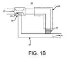
図1Aと一致して、図1Bは、入口22及び出口24を含む流体サンプル最適化装置20の実装を示す。上述したように、入口22は、静脈穿刺針等を介して、患者又は患者の流体源に接続してもよく、ここで、流体は圧力P1で供給され、これは患者自身の血圧とし得る。出口24は、Vacutainer(R)又はシリンジのような真空チューブ等の流体収集装置に接続してもよく、流体収集装置によって流体が圧力P1より低い圧力P2によって流体源から吸引される。Consistent with FIG. 1A, FIG. 1B shows an implementation of a fluid
流体サンプル最適化装置20は、入口22および出口24に接続され、汚染物質封じ込めリザーバ26の遠位端と出口24との間に空気透過性流体抵抗器27を有する汚染物質封じ込めリザーバ26をさらに含む。流体サンプル最適化装置20は、入口22及び出口24に接続されたサンプル経路28をさらに含む。サンプル経路28は、入口22に近接して設けられた抵抗器29を含む。The fluid
いくつかの実装では、図1Bに示すように、流体サンプル最適化装置20は加速部30を含んでもよく、それを通って移動する流体の流体圧力を減少させ、それによって、例えば、入口22から汚染物質封じ込めリザーバ26への流体の速度を増加させ得る。これは、流体の後続の部分又は量が抵抗器29を貫通して通過し、収集のために出口24を通って出力される前に、入口22から汚染物質封じ込めリザーバ26に流体の第1の部分又は量を優先的に導くのにさらに役立つ。加速部は、例えば、ベンチュリ経路において、より小さい断面積、又は狭窄領域、チョークポイント等を含み得る。加速部30の後には、汚染物質封じ込めリザーバ26のより大きな断面積が続いてもよく、これもまた、所定の容積の流体を保持するように構成し得る。いくつかの実装では、加速部30は、入口22からサンプル経路28への接続点に近接して配置してもよく、それによって汚染物質封じ込めリザーバ26が充填されると、血液の後続の部分又は量は、抵抗器29を克服して、後続の部分又は量がサンプル経路28を通って出口24へ流れることを可能にするために、加速部30内の圧力を上昇させる。In some implementations, as shown in FIG. 1B, the fluid
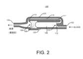
図2は、入口ポート102及び出口ポート104を含む流体サンプル最適化装置100を示す。入口ポート102は、患者の針、チューブ、アクセスポート、カテーテルポート等の体液サンプルアクセス装置と流体的に結合し得る。出口ポート104は、Vacutainer(R)セット等の流体収集装置と流体的に結合してもよく、これは、シールを破壊して、流体サンプル最適化装置100を介して入口ポート102から出口ポート104に真空に基づく動力を提供するために、真空シールされた収集チューブをその上に配置し得るシールされたサンプリング針を含み得る。また、出口ポート104は、シリンジ等の他の任意の収集装置に接続されてもよく、これは、プランジャーを使用して、流体サンプル最適化装置100を通して患者から流体を「引っ張る」ための圧力差を生成してもよく又はしなくてもよい。2 shows the fluid
さらに、流体サンプル最適化装置100は、入口ポート102に結合された近位端107と、出口ポート104に、又は出口ポートに向かって、少なくとも空気等により流体的に結合された遠位端109とを有する汚染物質封じ込めリザーバ106を含む。汚染物質封じ込めリザーバ106は、任意の形状及び/又は断面寸法を有し得る。さらに、入口ポート102から汚染物質封じ込めリザーバ106への移行は、直線又は曲線とし得る。いくつかの実装では、汚染物質封じ込めリザーバ106を横断又はバイパスする流体が血液である場合に、鋭利な縁部又は角部を有しない滑らかな移行が溶血を回避し得るので、汚染物質封じ込めリザーバ106は、円筒形であるか又はそれ以外の円形の断面を有する。Additionally, the fluid
流体サンプル最適化装置100は、汚染物質封じ込めリザーバ106内に配置されかつ固定された、本明細書では「プラグ」とも呼ばれる空気透過性流体抵抗器108をさらに含む。空気透過性流体抵抗器108は、流体に供給される時間及び圧力に応じて、その中の流体の通過に対する完全な又は部分的な抵抗器とし得る。いくつかの好ましい実装によれば、空気透過性流体抵抗器108は、汚染物質封じ込めリザーバ106の近位端107に面しているか又は向かっている前面と、汚染物質封じ込めリザーバ106の遠位端109に面しているか又は向いている背面とを有する。空気透過性流体抵抗器108は、真空が出口ポート104に印加され、血液等の体液の第1の量によって押されたときに、空気透過性流体抵抗器108を通って、流体サンプル最適化装置100の出口ポート104に向かって及び外に、汚染物質封じ込めリザーバ106から空気を通過させる。The fluid
本明細書に記載される実装と同様に、空気透過性流体抵抗器108は、0.05mm未満から5cmまで又はそれ以上の厚さ又は長さを有してもよく、均一又は変化する密度を有し得る。例えば、空気透過性流体抵抗器108は、汚染物質封じ込めリザーバ106の近位端107に面する側では、より密度が低く、より多孔質であり、汚染物質封じ込めリザーバ106の遠位端109に向かってより密度が高く、より多孔質ではなくてもよい。空気透過性流体抵抗器108の直径は、空気透過性流体抵抗器108の外側部分と汚染物質封じ込めリザーバ106の内壁との間を血液が通過するのを防止するように、汚染物質封じ込めリザーバ106の内部寸法と一致する。また、空気透過性流体抵抗器108は、多様な材料から構築された複数の構成要素の形態であってもよい。As with the implementations described herein, the air permeable
いくつかの実装では、血液等の流体と接触すると膨張する材料を空気透過性流体抵抗器108に含浸させることができる。図2には、汚染物質封じ込めリザーバ106の遠位端109に向かって配置されるように示されているが、空気透過性流体抵抗器108は、汚染物質封じ込めリザーバの長さに沿ってどこに配置してもよく、空気透過性流体抵抗器108を形成する材料の吸収性の程度に応じて、近位端107から遠位端109まで延びることができる。空気透過性流体抵抗器108を形成する濾過媒体は、表面改質されてもよく、又は、例えば、タイミング及び/又は流体容積等の特定の性能要件に応じて機能性を高めるために、添加剤が多孔質マトリックスに組み込まれてもよい。In some implementations, the air permeable
いくつかの実装では、空気透過性流体抵抗器108は、空気を通過させるように構成されている材料又は材料の組み合わせで形成されるが、これは第1の量の体液の一部で飽和し得る。空気透過性流体抵抗器108は、少なくとも部分的に、多孔性ポリマー又はプラスチック、及び/又は綿、麻等の天然繊維材料によって形成し得る。いくつかの実装では、空気透過性流体抵抗器108は、二つの部分、すなわち、空気に対して透過性であって、(出口104に向かって)遠位端ではほとんど流体に対して不透過性である第1の部分と、(汚染物質封じ込めリザーバ106に向かって)近位端において血液との接触時にシールする添加剤を含む第2の部分とから形成し得る。この構成は、添加剤がサンプル経路を通って収集ボトル等に流出する流体と混合することを防ぎ得る。空気透過性流体抵抗器108は、流体の第1の部分の少なくとも一部を受容して捕捉してもよく、それによって汚染物質をその中に捕捉し得る。In some implementations, the air permeable
流体サンプル最適化装置100は、汚染物質封じ込めリザーバ106の近位端107の近くの入口ポートに接続された近位端111と、出口ポート104に結合された遠位端113とを有するサンプル経路110をさらに含む。サンプル経路110は、チャネル、チューブ、トラック、通路、部分、空洞、ハウジング、ケーシング等として形成し得る。空気透過性流体抵抗器108は、体液の第2の部分がサンプル経路110を介して汚染物質封じ込めリザーバ106をバイパスするのに十分な時間流体の第1の部分を保持するように構成される。図2に示すように、サンプル経路110は、汚染物質封じ込めリザーバ106の方向と実質的に平行に流体サンプル最適化装置100を横断し得る。いくつかの実装では、汚染物質封じ込めリザーバ106の断面積は、サンプル経路110の断面積よりも大きくしてもよく、これは、入口102から汚染物質封じ込めリザーバ106内に第1の量の流体を優先的に導くことを支援し得る。The fluid
入口ポート102、汚染物質封じ込めリザーバ106の近位端、及びサンプル経路110の近位端は共に接合部112を形成する。接合部112は、例えば、サンプル経路の近位端に通じる多数の湾曲した通路を含んでもよく、これは、最初に汚染物質封じ込めリザーバ106への流体の流れを促進し、次いで汚染物質封じ込めリザーバ106をバイパスしてサンプル経路110の中を通過するように構成し得る。重要なことには、種々の従来技術の血液分流又は血液サンプル最適化装置とは異なり、接合部112は受動的流体制御に依存し、流体の流れを分流又は切り換えるための能動スイッチ、弁又は他の機械的可動装置を含まない。The
流体力学的には、初期経路の流れに対する抵抗(R1)は、サンプル経路の流れに対する抵抗(R2)より小さくなければならない。汚染物質封じ込めリザーバが充填されると、血液が空気透過性抵抗器を通って移動することが防止されるので、抵抗が増加する。空気は簡単に流れるが、血液は異なる。R1がある点で増加すると、スケールが頂点に達し、R1はR2より大きくなる。その時点で、血液はサンプル経路に流れる。R2は、長さ、直径、及びある程度のジオメトリに適用される変化に応じて大きくし得る。R1は、本明細書にさらに詳細に記載するように、同じ手段又は変形によって、及びプラグの通気性を管理することによって低減し得る。Hydrodynamically, the resistance to flow in the initial pathway (R1) must be less than the resistance to flow in the sample pathway (R2). As the contaminant containment reservoir fills, the resistance increases as blood is prevented from moving through the air permeable resistor. Air flows easily, but blood does not. At some point, R1 increases, the scale tops out and R1 becomes greater than R2. At that point, blood flows into the sample pathway. R2 can be increased depending on the changes applied to the length, diameter, and to some extent geometry. R1 can be reduced by the same means or modifications, and by managing the breathability of the plug, as described in more detail herein.
いくつかの実装では、流体サンプル最適化装置100は、入口ポート102、出口ポート104、汚染物質封じ込めリザーバ106、及びサンプル経路110のうちの1つ以上を形成しかつ提供するハウジング120を含む。例えば、ハウジング120は、下部部材と嵌合する上部部材から形成されてもよく、上部部材及び下部部材の一方又は両方は、入口ポート102、出口ポート104、汚染物質封じ込めリザーバ106、及びサンプル経路110のうちの1つ以上を画定して提供するように、溝、チャネル、経路、領域、又は他の特徴で形成される。ハウジング120は、プラスチック(ポリカーボネートアクリル、PVC、ABS等)、金属等のような丈夫で弾力性のある材料で作られてもよく、使用前に消毒して、微生物を含まない清潔で消毒された状態で使用し得る。入口ポート102及び/又は出口ポート104は、ルアーコネクタ又はねじ付き接続部等のコネクタをさらに含むか又はコネクタを装着し得る。In some implementations, the fluid
図3は、患者針203を有する血液サンプリング経路に接続された流体サンプル最適化装置201及びサンプル収集装置205を含む流体サンプリングシステム200を示しており、これは、一部の実装では、1つ以上の真空サンプルボトルを受容するシールされたサンプル収集針を有するアダプタを含む。患者針203は、“Needle Assembly with Needle Safety Shield”と題された米国特許出願第16/045,321号に記載されているような安全型の血管アクセス針であってもよく、その内容は全ての目的のために参照により本明細書に組み込まれる。3 illustrates a
流体サンプル最適化装置201は、患者針203に接続された入口ポート202と、サンプル収集装置205に接続された出口ポート204と、空気透過性流体抵抗器208を有する汚染物質封じ込めリザーバ206と、入口ポート202に流体的に結合された近位端及び出口ポート204に流体的に接続された遠位端を有するサンプル経路210とを含む。流体サンプル最適化装置201は、入口ポート202、出口ポート204、汚染物質封じ込めリザーバ206、及びサンプル経路210のうちの1つ以上を収容しかつ画定するハウジング220をさらに含み得る。ハウジング220は、滅菌されやすいか、又は抗菌特性を有する可能性があるが、入口ポート202、出口ポート204、汚染物質封じ込めリザーバ206及びサンプル経路210、並びにその中の任意の構成要素を外部汚染物質から遮蔽することもできる任意の剛性材料で形成し得る。The fluid
汚染物質封じ込めリザーバ206及びサンプル経路210の各々は、接合部212を介して入口202に接続してもよく、これは、血液のような流体の第1の部分が汚染物質封じ込めリザーバ206内に吸引され、引っ張られ、又はその他のやり方で流れることを可能にして、空気透過性流体抵抗器208を介してその中の空気を移動させ、少なくとも一部が、少なくとも一時的に、汚染物質封じ込めリザーバ206内に維持され、及び血液の第2の部分が汚染物質封じ込めリザーバ206をバイパスして、出口ポート204及びサンプル収集装置205に向かってサンプル経路210に流れることを可能にするようにサイズ決め及び構成される。Each of the
サンプル収集装置205は、Vacutainer(R)型装置であってもよく、収集アダプタは、真空シールされた収集ボトルによって貫通され得るエラストマーシールによってシールされた収集針を有し、収集ニードルを露出させかつ収集ボトルの隔膜への収集針の挿入を可能にする。収集ボトル内の真空は、流体サンプル最適化装置201を介して患者から体液を引き出すことを支援する力であり得る。The
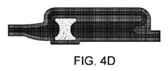
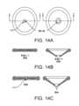
図4A~4Dは、流体サンプル最適化装置100/201の動作を示し、特に血液サンプリングの文脈で説明されるが、他の種類の体液を収集又はサンプリングすることもできる。図3を参照すると、図4Aに示されるように、流体収集装置が流体サンプル最適化装置の出口で低圧を生成する場合、例えば、収集ボトル又はチューブが収集アダプタに挿入される場合に、患者の静脈穿刺(より詳細には、患者の血管血圧)等によって、出口と入口との間の圧力差は、空気を流体サンプル最適化装置から強制的に押し出して収集ボトルに押し込み、血液がその後方で満たされる。Figures 4A-4D illustrate the operation of the fluid
図示された実装では、空気は、2つの平行な経路を通って、すなわち、汚染物質封じ込めリザーバ内のプラグを通って及びサンプル経路を通って流れることができる。各経路を通る流量は、各経路内の抵抗に比例し得る。したがって、流体サンプル最適化装置の最適な構成は、汚染物質封じ込めリザーバの容積、入口を汚染物質封じ込めリザーバ及びサンプル経路と接続する接合部の配置、入口、汚染物質封じ込めリザーバ及びサンプル経路の相対的断面寸法、プラグの抵抗率、プラグの位置及びサイズ、入口、汚染物質封じ込めリザーバ及びサンプル経路等の間の様々な遷移又はインターフェースの曲率等を考慮することを含む。In the illustrated implementation, air can flow through two parallel paths, namely, through the plug in the contaminant containment reservoir and through the sample path. The flow rate through each path can be proportional to the resistance in each path. Thus, the optimal configuration of the fluid sample optimization device includes consideration of the volume of the contaminant containment reservoir, the placement of the junctions connecting the inlet with the contaminant containment reservoir and the sample path, the relative cross-sectional dimensions of the inlet, contaminant containment reservoir and sample path, the resistivity of the plug, the location and size of the plug, the curvature of the various transitions or interfaces between the inlet, contaminant containment reservoir and sample path, etc.
図4Bは、汚染物質封じ込めリザーバを満たす血液を示す。空気がプラグを十分迅速に通過しない場合、すなわち、プラグを通る抵抗がサンプル経路を通る抵抗よりも低くない場合、汚染物質封じ込めリザーバ内に圧力が蓄積し、汚染物質封じ込めリザーバが流体で充填される前に、流体をサンプル経路に押し出す。図4Cは、充填された汚染物質封じ込めリザーバを示す。一旦全ての空気が汚染物質封じ込めリザーバから(プラグ及びサンプル経路を通って)押し出されると、流体はプラグに当たり、プラグを通るその進行は遅くなり、場合によっては停止する。これにより、流体がサンプル経路を流れるように押し出すことができ、血液の最初の容積が汚染物質封じ込めリザーバに捕捉される。この時点では、プラグを流れる流体がない可能性がある。図6は、空気が装置、特に汚染物質封じ込めリザーバから流された後の流体の流れを示す。後続の血液量は、サンプル経路の遠位端に向かって、及び出口ポートに向かって外に、最も抵抗の少ない経路(より低い圧力勾配)に従って、サンプル経路に流入して通過する。Figure 4B shows blood filling the contaminant containment reservoir. If the air does not pass through the plug quickly enough, i.e., if the resistance through the plug is not lower than the resistance through the sample path, pressure will build up in the contaminant containment reservoir and push the fluid into the sample path before the contaminant containment reservoir fills with fluid. Figure 4C shows the contaminant containment reservoir filled. Once all the air has been pushed out of the contaminant containment reservoir (through the plug and sample path), the fluid will hit the plug and its progress through the plug will slow and possibly stop. This allows the fluid to be pushed to flow through the sample path and the initial volume of blood will be captured in the contaminant containment reservoir. At this point, there may be no fluid flowing through the plug. Figure 6 shows the flow of fluid after the air has been flushed out of the device, specifically the contaminant containment reservoir. The subsequent blood volume flows into and through the sample pathway following the path of least resistance (lower pressure gradient) toward the distal end of the sample pathway and out toward the exit port.
流体の流れは、完全に停止させられるか、又はゆっくりとプラグに流入することを可能にし得る。ただし、使用中に反対側に達してサンプル経路と混合することは起こらない。Fluid flow can be stopped completely or allowed to slowly flow into the plug, but without reaching the other side and mixing with the sample path during use.
プラグを通る空気の流れの抵抗をサンプル経路を通るよりも低くすることは、以下の(1)及び(2)によって達成し得る。(1)断面積-プラグの面積がサンプル経路の面積よりもはるかに大きい場合、抵抗はより低くなる。(2)サンプル経路を長くすると抵抗が大きくなるが、空気の流れの方が流体の流れよりも効果が低くなる。Making the air flow through the plug less resistant than through the sample path can be achieved by (1) and (2) below: (1) Cross-sectional area - if the area of the plug is much larger than the area of the sample path, the resistance will be lower. (2) Making the sample path longer will increase the resistance, but the air flow will be less effective than the fluid flow.
第1の量の流体は、最初にジオメトリに基づいて汚染物質封じ込めリザーバを満たすことができる。図4A~4Dに示すように、流体の慣性は、角部をサンプル経路に向けるのではなく、流体が汚染物質封じ込めリザーバ内に直線的に移動し続けるように流体を促す。いくつかの実装では、汚染物質封じ込めリザーバ及びサンプル経路、又はそれらの任意の入口及び出口を、流体の流れに対する抵抗を増減させるために、異なるやり方でコーティングし得る。例えば、汚染物質封じ込めリザーバの壁を親水性コーティングでコーティングし、サンプル経路の壁(又は少なくとも入口)を疎水性コーティングでコーティングすることは、汚染物質封じ込めリザーバを最初に充填するのに役立つ。親水性コーティングは、ポリウレタン(PU)、ポリビニルピロリドン(PVP)、ポリアクリル酸(PAA)、及び/又はポリエチレンオキシド(PEO)の1つ以上を含み得る。疎水性コーティングは、ポリテトラフルオロエチレン(PTFE)を含み得る。サンプリング経路内の抵抗は、血液又は流体との接触時に溶解する溶解性生体適合性材料を経路内に挿入することによっても増大させることができ、汚染物質封じ込めリザーバが流体で満たされると、サンプル経路を通る流れに対する抵抗が低減する。A first amount of fluid can initially fill the contaminant containment reservoir based on the geometry. As shown in FIGS. 4A-4D, the inertia of the fluid encourages the fluid to continue moving in a straight line into the contaminant containment reservoir, rather than turning a corner into the sample path. In some implementations, the contaminant containment reservoir and the sample path, or any of their inlets and outlets, can be coated differently to increase or decrease resistance to fluid flow. For example, coating the walls of the contaminant containment reservoir with a hydrophilic coating and coating the walls (or at least the inlet) of the sample path with a hydrophobic coating can help initially fill the contaminant containment reservoir. The hydrophilic coating can include one or more of polyurethane (PU), polyvinylpyrrolidone (PVP), polyacrylic acid (PAA), and/or polyethylene oxide (PEO). The hydrophobic coating can include polytetrafluoroethylene (PTFE). The resistance in the sampling pathway can also be increased by inserting a dissolvable biocompatible material into the pathway that dissolves upon contact with blood or fluid, reducing the resistance to flow through the sample pathway when the contaminant containment reservoir fills with fluid.
別の実装では、無害な不活性又は非反応性の生体適合性材料、すなわち、血液検査結果に影響を及ぼさない材料を、サンプリング経路を遮断するために、この装置に、又は少なくとも汚染物質封じ込めリザーバへの接合部に配置し得る。この材料は、血液又は流体が接触したときに溶解するように構成し得る。このような材料は、汚染物質封じ込めリザーバが略瞬時に充填されるので、数分の1秒の間、血流を阻害するようなサイズ及び構成とし得る。In another implementation, a non-hazardous, inert or non-reactive biocompatible material, i.e., a material that does not affect blood test results, may be placed in the device, or at least at the junction to the contaminant containment reservoir, to block the sampling path. The material may be configured to dissolve upon contact with blood or fluid. Such a material may be sized and configured to impede blood flow for a fraction of a second as the contaminant containment reservoir fills nearly instantly.
図5は、チューブ又は他のタイプの流体搬送機構から形成され、装置の両端にあるYサイトコネクタ306A及び306Bを介して平行又は同様の方向の経路を形成する汚染物質封じ込めリザーバ302及びサンプル経路304を有する、流体サンプル最適化装置300のハウジングレスの実装を示す。Yサイトコネクタ306A及び306Bは、任意の方向又は整列で設けることができ、既知の断面直径及び長さを有するチューブとして実装される場合、汚染物質封じ込めリザーバ302を所定の容積で提供するのに十分な間隔で配置され得る。汚染物質封じ込めリザーバ302は、流体の流れに対して抵抗性であるが空気の通過を可能にする空気透過性流体抵抗器308を含み、それにより、流体の第1の量又はアリコートが汚染物質封じ込めリザーバ302を満たした後で、後続の量の流体が汚染物質封じ込めリザーバ302をバイパスし、流体収集装置による最終的な収集のためにサンプル経路304を流れる。5 shows a housingless implementation of a fluid sample optimization device 300 with a
流体サンプル最適化装置300を使用するシステムは、Yサイトコネクタ306Aに接続された患者針301と、Yサイトコネクタ306Bに接続されたシールされたサンプリング針を有するサンプル収集装置303とを含み得る。流体サンプル最適化装置300のチューブは、可撓性又は剛性であり得る。チューブの少なくとも一部は、臨床医がその中の血液の流れを見ることができるように、半透明の材料で作ることができる。流体サンプル最適化装置300は、少なくとも部分的に空気透過性血液抵抗材料から形成され得るフィルタ308を含み得る。フィルタ308は、汚染物質封じ込めリザーバ内の空気を、真空力、又はサンプル収集装置303と汚染物質封じ込めリザーバ302との間に負の圧力差を生じさせる他の機構に基づいて、フィルタ308を通ってそこから移動させることを可能にする。A system using the fluid sample optimization device 300 may include a
いくつかの実装において、流体サンプル最適化装置300は、フラッシュチャンバとして機能してもよく、患者の静脈穿刺時に、流体サンプル最適化装置300の出口接合部における少なくとも部分的に真空力に基づいて、血液が汚染物質封じ込めリザーバ302の少なくとも一部に「フラッシュ」又は突然存在し得る。真空圧は、汚染された血液を抵抗器を越えて(汚染された血液を捕捉せずに)汚染物質チャンバに優先的に引き込む。In some implementations, the fluid sample optimization device 300 may function as a flash chamber, such that upon venipuncture of a patient, blood may be "flushed" or suddenly present in at least a portion of the
図6Aは、入口402及び出口404を含む流体サンプル最適化装置400を示す。入口402は、チューブ又はそのインターフェース等の外部装置に接続するための入口ポート、コネクタ又はインターフェースを含み得る。入口402は、静脈穿刺針等を介して、患者又は患者の流体源に接続されてもよく、ここで、流体は圧力P1で供給され、これは患者自身の血圧であってもよい。出口404は、チューブ又はそのインターフェース等の外部装置に接続するための出口ポート、コネクタ又はインターフェースを含み得る。上述のように、例えば、出口404は、Vacutainer(R)又はシリンジのような真空チューブ等の流体収集装置に接続してもよく、流体収集装置によって流体が圧力P1より低い圧力P2によって流体源から吸引される。圧力差によって、流体サンプル最適化装置400を大気及び大気圧に対して閉じることができ、すなわち、流体サンプル最適化装置400は、少なくとも使用時に、外部大気へのいかなる通気口又は経路も含む必要がない。6A shows a fluid sample optimization device 400 including an
流体サンプル最適化装置400は、入口402および出口404に接続され、汚染物質封じ込めリザーバ406の遠位端と出口404との間に空気透過性流体抵抗器407を有する汚染物質封じ込めリザーバ406をさらに含む。本明細書にさらに記載されるように、汚染物質封じ込めリザーバ406は、所望の量の流体を保持するようなサイズにしてもよく、汚染物質封じ込めリザーバ406を少なくとも部分的に満たす吸収性材料を含み得る。また、本明細書にさらに記載されるように、汚染物質封じ込めリザーバ406は、蛇行経路、異なる断面及び容積の一連のチャンバとして構成されてもよく、及び/又は、逆流、すなわち入口402に向かう流れを最小化するために、内部表面から延びるライフリング又はバッフルを含み得る。例えば、汚染物質封じ込めリザーバ406は、1つ以上のチャネル406A及び1つ以上のチャンバ406Bを含んでもよく、それらの全ては、その中に任意の汚染物質を封じ込めるだけでなく、所定の容積の流体を受容、搬送又は封じ込めるように相互接続し得る。The fluid sample optimization device 400 further includes a contaminant containment reservoir 406 connected to the
空気透過性血液抵抗器407は、汚染物質封じ込めリザーバ406への流体の流れが少なくとも部分的に停止される空気透過性流体抵抗器407に流体が接触するまで、入口402と出口404との間に印加される圧力差によって流体源から引き出される流体の第1の部分又は量を入口402に流入させて、汚染物質封じ込めリザーバ406に流入させることが可能であり、その中で空気を移動させる。The air
流体サンプル最適化装置400は、入口402及び出口404に接続されたサンプル経路408をさらに含む。サンプル経路408は、入口402に近接して設けられた抵抗プラグ409を含む。入口402と出口404との間の圧力差は、流体の第1の部分又は量を汚染物質封じ込めリザーバ406に引き込むことができるのと同時に、抵抗プラグ409は、流体の第1の部分又は量が汚染物質封じ込めリザーバ406に入るまで、サンプル経路408への流体の流れに抵抗し、阻止し、制限し又は妨げるように構成される。The fluid sample optimization device 400 further includes a
流体サンプル最適化装置400は、入口402、出口404、汚染物質封じ込めリザーバ406、サンプル経路408、又は場合によっては空気透過性流体抵抗器407及び抵抗プラグ409のような他の構成要素のうちの1つ以上を画定し得るハウジング401をさらに含み得る。ハウジング401は、1つ以上の部分に形成し得る。例えば、図6Aの例に示すように、ハウジング401は、下部ハウジング部分424と嵌合する上部ハウジング部分422を含んでもよく、これらは音波溶接、熱接合、接着等によって互いに嵌合及びシールし得る。The fluid sample optimization device 400 may further include a
本明細書に記載されるように、抵抗プラグ409は、流体の第1の部分又は量が汚染物質封じ込めリザーバ406に入った後で、流体の第2の部分及び/又は後続の部分又は量が、依然として入口402と出口404との間の圧力差の力の下で、入口402からサンプル経路408を通って出口404へ流れることを可能にするように構成される。抵抗プラグ409は、真空圧の蓄積を可能にするために入口402から離れたサンプル経路408内に陥入されてもよく、また、溶解性材料が、出口404に向かって引き込まれ続ける流体によって溶解を開始することを可能にするためにパイロット孔又は小さな毛管、開口部、アイリス等を含んでもよい。したがって、サンプル経路408の一部分、入口402、及び/又は汚染物質封じ込めリザーバ406は、抵抗プラグ409に近接し、かつサンプル経路408の主要部分に対向する接合部411を形成してもよく、これにより、汚染物質封じ込めリザーバ406が充填された後に、抵抗プラグ409を介してより良好な流体アクセスのために真空圧が蓄積されることを可能にする。As described herein, the
流体が汚染物質封じ込めリザーバ406を満たすと、流体と抵抗プラグ409との間の接合部411に一定量の空気を捕捉することができる。空気を逃がすやり方がなければ、流体は、サンプル経路406を流れることができるように、抵抗プラグ409の少なくとも一部を形成する溶解性材料に到達することができないであろう。したがって、図6Bから図6Iに示すように、流体が汚染物質封じ込めリザーバ406を満たし、かつ空気透過性流体抵抗器407を塞ぐときに、収集装置の完全な真空圧力に曝された後にのみ空気が流れることを可能にする抵抗プラグ409を通る又はその周囲の空気経路を設けることができ、それによって、汚染物質封じ込めリザーバ406が完全に充填され、かつ/又は汚染物質がそこに収容されるまで、流体が抵抗プラグ409内の溶解性材料と接触しない。When fluid fills the contaminant containment reservoir 406, a certain amount of air may be trapped at the junction 411 between the fluid and the
図6Bは、薄膜材料として形成し得る薄膜431としての抵抗プラグ409の変形例を示す。いくつかの実装では、フィルム431は、少なくとも部分的に、溶解可能な又は容易に引き裂かれる材料によって形成し得る。フィルム431は、溶解又は引き裂きプロセスを開始する機構として小さなオリフィス432又はパイロット孔を有する。図6Cは、静止した定常状態で閉じられているが、抵抗器の一方又は両方の反対側又は表面に圧力が加えられたときに開いて流体が流れることを許容し得るスリット433を有するフィルム431を示す。一部の実装では、図6Dに示すように、スリット433は、「X」又は線形スリット、湾曲スリット、星形スリット等の他の構成として形成し得る。図6Eに示すように、フィルム431は、血液のような体液ではなく、空気を通過させることが可能な多孔質膜として形成し得る。図6Fに示すように、フィルム431は、所定の圧力が加えられたときにフィルム431の周りに空気が「漏れる」ように、サンプル経路408の入口で上部ハウジング部分422と下部ハウジング部分424との間に配置し得る。6B shows a variation of the
図6G~6Iは、円筒形プラグ部材435としての抵抗プラグ409を示すが、抵抗プラグ409は、それ以外の形状、例えば、正方形、長方形、又は他の形状に形成することもできる。円筒状プラグ部材435は、図6Gに示すように小さなパイロット孔を備えてもよく、図6Hに示すように空気に対して多孔性であってもよい。抵抗プラグ409は、円筒形プラグ部材435として又は他の形状として実装されるかに関わらず、所定の圧力が加えられたときに円筒形プラグ部材435の周りに空気が「漏れる」ように、サンプル経路408の入口で上部ハウジング部分422と下部ハウジング部分424との間に配置し得る。Although Figures 6G-6I show the
本明細書にさらに記載され、図7に示されるように、サンプル経路への開口のための抵抗プラグ500は、溶解性材料504が含浸されたメッシュ502の少なくとも一部を含む組成物から形成し得る。ある特定の実装では、抵抗プラグ500は、溶解性材料502を支持するメッシュ材料を含み得る。メッシュ材料は、例えば、50~100μmのナイロン又はプラスチック糸のメッシュのようなプラスチック又はナイロンのメッシュとし得る。溶解性材料504は、硬質のプラグ又はフィルムとして形成できない場合があり、メッシュ502又は他の多孔質材料に含浸させることができる。溶解性材料504は、血液等の流体との接触によって溶解可能である。溶解性材料504は、サンプル又は収集された流体試料の実験室試験に対して不活性又は非反応性であるように作成され、これらは、しばしば、特定の細菌若しくはウイルス、又はそれらの抗体、又は流体サンプル中に存在する他の病原体について試験するための培養物を提供される。As further described herein and shown in FIG. 7, a
図8に示すように、抵抗プラグ600は、上述のようにメッシュ602から形成することもできるが、シリコーングリースのような非溶解性粘性材料604と重ねられるか又は一体化される。粘性材料604は、メッシュ602又は他の多孔質材料上に広げることができる。抵抗プラグ600を横切る圧力差が十分に高くなると、図8Bに示すように、流体サンプルが流れるための開口部が形成されるように、粘性材料604がメッシュ602の開口を通って引っ張られる。最大でも、微量の粘性材料604のみが出口から出ることになるので、流体サンプルのいかなる試験又は培養に干渉することもない。As shown in FIG. 8, the
図9A~9Cに示すように、抵抗プラグ700は、初期状態において、貫通部材704上に伸張されるか、又は貫通部材上に配置され、貫通部材から離間された膜702から形成し得る。貫通部材704は、スパイク、ピン、ブレード、シャード等を含んでもよく、図9Bに示すような保持機構によって、図9Aに示すように、サンプリング経路への開口部の略中央に保持し得る。膜702は、ゴム又は他の弾性材料のような材料の弾性シートであってもよい。図9Cに示すように、汚染物質封じ込めリザーバが流体で満たされると、一定量の圧力が膜702に加えられ、膜をさらに伸長して貫通部材704に接触させる。膜702と穿刺部材704とが接触すると、膜702は、穿刺部材704によって穿刺されるか、又はその他のやり方で破壊されて、流体の後続の量又は部分がサンプル経路に流れるようにより大きな領域を開放する。9A-9C, the
図10A~11Bは、流体源から流体収集装置によって収集された流体サンプルを最適化するための流体サンプル最適化装置800及び900の様々な図を示し、流体サンプルの第1の部分は汚染物質を有する可能性がある。図10A及び図10Bに示すように、流体サンプル最適化装置800は、流体源と接続するように構成された入口802と、流体収集装置と接続するように構成された出口804と、入口802と出口804との間に接続されたサンプル経路808とを含む。流体サンプル最適化装置800は、入口802と出口804との間に接続された汚染物質封じ込めリザーバ806をさらに含む。入口802、出口804、汚染物質封じ込めリザーバ806及びサンプル経路808、及び場合によっては流体サンプル最適化装置800の他の構成要素のうちの1つ以上を、ハウジング内に収容し、及び/又はハウジング820によって画定し得る。10A-11B show various views of a fluid
汚染物質封じ込めリザーバ806は、好ましくは出口804の近くで、サンプル経路808に接続された空気透過性流体抵抗器812をさらに含む。汚染物質封じ込めリザーバ806は、入口802と出口804との間に圧力差が印加されると、流体源からの流体サンプルの第1の部分を受け入れ、空気透過性流体抵抗器812及び出口804を介して内部の空気を移動させるように配置される。空気透過性流体抵抗器812は、図12Aに示すように、特定の空気の流れの範囲に対して細長くされかつ構成されてもよく、血液又は他の体液のような非空気流体と接触すると自己シールし得る。The
流体サンプルの最初の部分を受け取り、汚染物質を汚染物質封じ込めリザーバ806内に封じ込めると、流体サンプルの後続の部分は、後続の圧力差が入口802と出口804との間に印加されるときに、サンプル経路808によって受け取られて入口802から出口804まで搬送され得る。いくつかの実装では、流体サンプル最適化装置800は、流体の最初の部分が汚染物質封じ込めリザーバ806内に受容されている間及びそれまで、最初に実質的にサンプル経路808を入口802から塞ぐ抵抗プラグ810を含む。Upon receiving an initial portion of the fluid sample and containing contaminants within the
図11A及び図11Bに示すように、流体サンプル最適化装置900は、流体源と接続するように構成された入口902と、流体収集装置と接続するように構成された出口904と、入口902と出口904との間に接続されたサンプル経路908とを含む。流体サンプル最適化装置900は、入口902と出口904との間に接続された汚染物質封じ込めリザーバ906をさらに含む。入口902、出口904、汚染物質封じ込めリザーバ906及びサンプル経路908、及び場合によっては流体サンプル最適化装置900の他の構成要素のうちの1つ以上を、ハウジング内に収容し、及び/又はハウジング920によって画定し得る。11A and 11B, the fluid
汚染物質封じ込めリザーバ906は、好ましくは、出口904の近くで、サンプル経路908に接続された空気透過性流体抵抗器912をさらに含む。汚染物質封じ込めリザーバ906は、入口902と出口904との間に圧力差が印加されると、流体源からの流体サンプルの第1の部分を受け入れ、空気透過性流体抵抗器912及び出口904を介して内部の空気を移動させるように配置される。空気透過性流体抵抗器912は、円筒形であって、特定の空気の流れの範囲のために構成してもよく、それぞれ図12B及び図12Cに示すように、血液又は他の体液のような非空気流体と接触するとシールする自己シール層を含むように多層にし得る。The
流体サンプルの最初の部分を受け取り、汚染物質を汚染物質封じ込めリザーバ906内に封じ込めると、流体サンプルの後続の部分は、後続の圧力差が入口902と出口904との間に印加されるときに、サンプル経路908によって受け取られて入口902から出口904まで搬送され得る。いくつかの実装では、流体サンプル最適化装置900は、流体の最初の部分が汚染物質封じ込めリザーバ906内に受容されている間及びそれまで、最初に実質的にサンプル経路908を入口902から塞ぐ抵抗プラグ910を含む。Upon receiving an initial portion of the fluid sample and containing contaminants within the
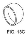
図13A~13Cは、円筒形プラグ(図13A)、フィルム又は膜(図13B)、又は可撓性キャップ(図13C)等の、抵抗プラグの様々な実装及び構成を示す。Figures 13A-13C show various implementations and configurations of resistive plugs, such as a cylindrical plug (Figure 13A), a film or membrane (Figure 13B), or a flexible cap (Figure 13C).
図14A~14Cは、開口部1000又はアイリスを有する抵抗プラグを示しており、これは、抵抗プラグに作用する異なる圧力に基づいて、異なる時間に流れることを許容又は防止するために、手動又は自動で選択的に作動/破壊される。いくつかの実装では、抵抗プラグは、実質的に中央に小さな開口部1000を有する弾性膜である。抵抗プラグを形成する膜の片側に圧力差が印加されると、それは偏向し、開口部1000のサイズを増大させ、流体が出力部に流れることを可能にする。代替的に、抵抗プラグは、開口部1000を覆い、開口部1000が作動すると邪魔にならなくなる剛性又は半剛性プラグ部材1002を含み得る。FIGS. 14A-14C show a resistive plug having an
いくつかの実施形態を上記で詳細に説明したが、他の修正も可能である。他の実施形態は、以下の特許請求の範囲内であってもよい。Although several embodiments have been described in detail above, other modifications are possible. Other embodiments may be within the scope of the following claims.
Claims (18)
Translated fromJapanese前記流体源と接続するように構成される入口と、
前記流体収集装置に接続するように構成される出口と、
前記入口と前記出口との間に接続されるサンプル経路であって、前記流体サンプルの第1の部分の少なくとも一部が前記サンプル経路に入ることを阻止するように構成される抵抗プラグをさらに有するサンプル経路と、
前記入口と前記出口との間に接続されるチャンバと、
を備え、
前記チャンバは、前記出口に近接して空気透過性流体抵抗器を有し、
前記チャンバは、前記入口と前記出口との間に圧力差が印加されたとき、前記流体源から前記流体サンプルの前記第1の部分を受け取って、前記空気透過性流体抵抗器及び前記出口を通ってその中の空気を移動させるように配置され、それによって、前記チャンバ内に、前記流体サンプルの前記第1の部分が受け取られると、前記流体サンプルの後続の部分は、前記入口と前記出口との間に後続の圧力差が印加されたときに、前記サンプル経路によって前記入口から前記出口へと搬送されることができ、
前記抵抗プラグは、第1の後続の圧力差によって貫通可能なフィルムを含む、
装置。 1.An apparatus for optimizing a fluid sample collected by a fluid collection device from a fluid source, comprising:
an inlet configured to connect to the fluid source;
an outlet configured to connect to the fluid collection device;
a sample pathway connected between the inlet and the outlet, the sample pathway further comprising a resistive plug configured to block at least a portion of a first portion of the fluid sample from entering the sample pathway ;
a chamber connected between the inlet and the outlet;
Equipped with
the chamber having an air permeable flow resistor proximate the outlet;
the chamber is arranged to receivethe first portion of the fluid sample from the fluid source and displace air therein through the air permeable flow resistor and the outlet when a pressure differential is applied between the inlet and the outlet, such that once the first portion of the fluid sample isreceived withinthe chamber , a subsequent portion of the fluid sample can be transported by the sample path from the inlet to the outlet when a subsequent pressure differential is applied between the inlet and the outlet;
the resistive plug includes a film penetrable by a first subsequent pressure differential;
Device .
前記流体源と接続するように構成される入口と、
前記流体収集装置に接続するように構成される出口と、
前記入口と前記出口との間に接続されるサンプル経路であって、前記流体サンプルの第1の部分の少なくとも一部が前記サンプル経路に入ることを阻止するように構成される抵抗プラグをさらに有するサンプル経路と、
前記入口と前記出口との間に接続されるチャンバと、
を備え、
前記チャンバは、前記出口に近接して空気透過性流体抵抗器をさらに有し、
前記チャンバは、前記入口と前記出口との間に圧力差が印加されたとき、前記流体源から前記流体サンプルの前記第1の部分を受け取って、前記空気透過性流体抵抗器及び前記出口を通ってその中の空気を移動させるように配置され、それによって、前記チャンバ内に、前記流体サンプルの前記第1の部分が受け取られると、前記流体サンプルの後続の部分は、前記入口と前記出口との間に後続の圧力差が印加されたときに、前記抵抗プラグを通して押し込まれて、前記サンプル経路によって前記入口から前記出口へと搬送されることができ、
前記抵抗プラグは、第1の後続の圧力差によって貫通可能なフィルムを含む、
装置。 1.An apparatus for optimizing a fluid sample collected by a fluid collection device from a fluid source, comprising:
an inlet configured to connect to the fluid source;
an outlet configured to connect to the fluid collection device;
a sample pathway connected between the inlet and the outlet, the sample pathway further comprising a resistive plug configured to block at least a portionof afirst portion of the fluid sample from entering the sample pathway;
a chamber connected between the inlet and the outlet;
Equipped with
the chamber further comprising an air permeable flow resistor proximate the outlet;
the chamber is arranged to receive the first portion of the fluid sample from the fluid source and displace air therein through the air permeable flow resistor and the outlet when a pressure differential is applied between the inlet and the outlet, such that uponreceipt of the first portion of the fluid sample withinthe chamber , a subsequent portion of the fluid sample can be forced through the resistance plug and transported by the sample pathway from the inlet to the outlet when a subsequent pressure differential is applied between the inlet and the outlet;
the resistive plug includes a film penetrable by a first subsequent pressure differential ;
Device .
入口と、
出口と、
前記入口と前記出口との間に接続されるサンプル経路と、
前記入口と前記出口との間に接続されるチャンバと、
を備え、
前記チャンバは、前記出口に近接して空気透過性流体抵抗器を有し、
前記チャンバは、前記入口と前記出口との間に圧力差が印加されたとき、前記流体サンプルの第1の部分を受け取って、前記空気透過性流体抵抗器及び前記出口を通ってその中の空気を移動させるように配置され、それによって、前記チャンバ内に、前記流体サンプルの前記第1の部分が受け取られると、前記流体サンプルの後続の部分は、前記入口と前記出口との間に後続の圧力差が印加されたときに、前記サンプル経路によって前記入口から前記出口へと搬送されることができ、
前記サンプル経路は、前記チャンバ内に前記流体サンプルの前記第1の部分が受け取られている間に、前記流体サンプルの前記第1の部分の少なくとも一部が前記サンプル経路に入ることを阻止するように構成される抵抗プラグをさらに含み、
前記抵抗プラグは、第1の後続の圧力差によって貫通可能なフィルムを含む、
装置。 1.An apparatus for optimizing a fluid sample, comprising:
The entrance and
The exit,
a sample path connected between the inlet and the outlet;
a chamber connected between the inlet and the outlet;
Equipped with
the chamber having an air permeable flow resistor proximate the outlet;
the chamber is arranged to receive afirst portion of the fluid sample and displace air therein through the air permeable flow resistor and the outlet when a pressure differential is applied between the inlet and the outlet, such that once the first portion of the fluid sample isreceived withinthe chamber , a subsequent portion of the fluid sample can be transported by the sample path from the inlet to the outlet when a subsequent pressure differential is applied between the inlet and the outlet;
the sample path further comprising a resistive plug configured to block at least a portion of the first portion of the fluid sample from entering the sample path while the first portion of the fluid sample is received in the chamber;
the resistive plug includes a film penetrable by a first subsequent pressure differential ;
Device .
前記流体源と接続するように構成される入口と、an inlet configured to connect to the fluid source;
前記流体収集装置に接続するように構成される出口と、an outlet configured to connect to the fluid collection device;
前記入口と前記出口との間に接続されるサンプル経路であって、前記流体サンプルの第1の部分の少なくとも一部が前記サンプル経路に入ることを阻止するように構成される抵抗プラグをさらに有するサンプル経路と、a sample pathway connected between the inlet and the outlet, the sample pathway further comprising a resistive plug configured to block at least a portion of a first portion of the fluid sample from entering the sample pathway;
前記入口と前記出口との間に接続されるチャンバと、a chamber connected between the inlet and the outlet;
を備え、Equipped with
前記チャンバは、前記出口に近接して空気透過性流体抵抗器を有し、the chamber having an air permeable flow resistor proximate the outlet;
前記チャンバは、前記入口と前記出口との間に圧力差が印加されたとき、前記流体源から前記流体サンプルの第1の部分を受け取って、前記空気透過性流体抵抗器及び前記出口を通ってその中の空気を移動させるように配置され、それによって、前記チャンバ内に、前記流体サンプルの前記第1の部分が受け取られると、前記流体サンプルの後続の部分は、前記サンプル経路によって前記入口から前記出口へと搬送されることができ、the chamber is arranged to receive a first portion of the fluid sample from the fluid source and displace air therein through the air permeable flow resistor and the outlet when a pressure differential is applied between the inlet and the outlet, such that upon receipt of the first portion of the fluid sample into the chamber, subsequent portions of the fluid sample can be transported by the sample path from the inlet to the outlet;
前記抵抗プラグは、前記流体サンプルの第1の後続の部分と接触すると溶解する溶解性材料を有するメッシュを含む、装置。The resistive plug includes a mesh having a dissolvable material that dissolves upon contact with a first subsequent portion of the fluid sample.
前記流体源と接続するように構成される入口と、an inlet configured to connect to the fluid source;
前記流体収集装置に接続するように構成される出口と、an outlet configured to connect to the fluid collection device;
前記入口と前記出口との間に接続されるサンプル経路であって、前記流体サンプルの第1の部分の少なくとも一部が前記サンプル経路に入ることを阻止するように構成される抵抗プラグをさらに有するサンプル経路と、a sample pathway connected between the inlet and the outlet, the sample pathway further comprising a resistive plug configured to block at least a portion of a first portion of the fluid sample from entering the sample pathway;
前記入口と前記出口との間に接続されるチャンバと、a chamber connected between the inlet and the outlet;
を備え、Equipped with
前記チャンバは、前記出口に近接して空気透過性流体抵抗器をさらに有し、the chamber further comprising an air permeable flow resistor proximate the outlet;
前記チャンバは、前記入口と前記出口との間に圧力差が印加されたとき、前記流体源から前記流体サンプルの前記第1の部分を受け取って、前記空気透過性流体抵抗器及び前記出口を通ってその中の空気を移動させるように配置され、それによって、前記チャンバ内に、前記流体サンプルの前記第1の部分が受け取られると、前記流体サンプルの後続の部分は、前記抵抗プラグを通して押し込まれて、前記サンプル経路によって前記入口から前記出口へと搬送されることができ、the chamber is arranged to receive the first portion of the fluid sample from the fluid source and displace air therein through the air permeable flow resistor and the outlet when a pressure differential is applied between the inlet and the outlet, such that as the first portion of the fluid sample is received within the chamber, subsequent portions of the fluid sample can be forced through the resistance plug and transported by the sample pathway from the inlet to the outlet;
前記抵抗プラグは、前記流体サンプルの第1の後続の部分と接触すると溶解する溶解性材料を有するメッシュを含む、装置。The resistive plug includes a mesh having a dissolvable material that dissolves upon contact with a first subsequent portion of the fluid sample.
入口と、The entrance and
出口と、The exit,
前記入口と前記出口との間に接続されるサンプル経路であって、前記流体サンプルの第1の部分の少なくとも一部が前記サンプル経路に入ることを阻止するように構成される抵抗プラグをさらに有するサンプル経路と、a sample pathway connected between the inlet and the outlet, the sample pathway further comprising a resistive plug configured to block at least a portion of a first portion of the fluid sample from entering the sample pathway;
前記入口と前記出口との間に接続されるチャンバと、a chamber connected between the inlet and the outlet;
を備え、Equipped with
前記チャンバは、前記出口に近接して空気透過性流体抵抗器を有し、the chamber having an air permeable flow resistor proximate the outlet;
前記チャンバは、前記入口と前記出口との間に圧力差が印加されたとき、前記流体サンプルの前記第1の部分を受け取って、前記空気透過性流体抵抗器及び前記出口を通ってその中の空気を移動させるように配置され、それによって、前記チャンバ内に、前記流体サンプルの前記第1の部分が受け取られると、前記流体サンプルの後続の部分は、前記サンプル経路によって前記入口から前記出口へと搬送されることができ、the chamber is arranged to receive the first portion of the fluid sample and displace air therein through the air permeable flow resistor and the outlet when a pressure differential is applied between the inlet and the outlet, such that upon receipt of the first portion of the fluid sample into the chamber, a subsequent portion of the fluid sample can be transported by the sample path from the inlet to the outlet;
前記抵抗プラグは、前記流体サンプルの第1の後続の部分と接触すると溶解する溶解性材料を有するメッシュを含む、装置。The resistive plug includes a mesh having a dissolvable material that dissolves upon contact with a first subsequent portion of the fluid sample.
Priority Applications (1)
| Application Number | Priority Date | Filing Date | Title |
|---|---|---|---|
| JP2024154361AJP2025000660A (en) | 2019-04-01 | 2024-09-06 | Non-venting bodily fluid sample optimization device and system |
Applications Claiming Priority (3)
| Application Number | Priority Date | Filing Date | Title |
|---|---|---|---|
| US201962827783P | 2019-04-01 | 2019-04-01 | |
| US62/827,783 | 2019-04-01 | ||
| PCT/US2020/026276WO2020206047A1 (en) | 2019-04-01 | 2020-04-01 | Non-venting bodily fluid sample optimization device and system |
Related Child Applications (1)
| Application Number | Title | Priority Date | Filing Date |
|---|---|---|---|
| JP2024154361ADivisionJP2025000660A (en) | 2019-04-01 | 2024-09-06 | Non-venting bodily fluid sample optimization device and system |
Publications (2)
| Publication Number | Publication Date |
|---|---|
| JP2022519940A JP2022519940A (en) | 2022-03-25 |
| JP7554206B2true JP7554206B2 (en) | 2024-09-19 |
Family
ID=72607666
Family Applications (2)
| Application Number | Title | Priority Date | Filing Date |
|---|---|---|---|
| JP2021558648AActiveJP7554206B2 (en) | 2019-04-01 | 2020-04-01 | Non-breathable body fluid sample optimization device and system |
| JP2024154361APendingJP2025000660A (en) | 2019-04-01 | 2024-09-06 | Non-venting bodily fluid sample optimization device and system |
Family Applications After (1)
| Application Number | Title | Priority Date | Filing Date |
|---|---|---|---|
| JP2024154361APendingJP2025000660A (en) | 2019-04-01 | 2024-09-06 | Non-venting bodily fluid sample optimization device and system |
Country Status (6)
| Country | Link |
|---|---|
| US (2) | US12383174B2 (en) |
| EP (1) | EP3948211A4 (en) |
| JP (2) | JP7554206B2 (en) |
| CN (2) | CN112771362B (en) |
| IL (2) | IL286812B1 (en) |
| WO (1) | WO2020206047A1 (en) |
Families Citing this family (6)
| Publication number | Priority date | Publication date | Assignee | Title |
|---|---|---|---|---|
| EP4555929A3 (en) | 2017-09-12 | 2025-06-25 | Magnolia Medical Technologies, Inc. | Fluid control device |
| JP7229267B2 (en) | 2017-12-07 | 2023-02-27 | マグノリア メディカル テクノロジーズ,インコーポレイテッド | Fluid control device and method of use |
| WO2020163744A1 (en) | 2019-02-08 | 2020-08-13 | Magnolia Medical Technologies, Inc. | Devices and methods for bodily fluid collection and distribution |
| CN113784793B (en) | 2019-03-11 | 2023-09-19 | 木兰医药技术股份有限公司 | Fluid control device and method of using the same |
| MX2022001587A (en)* | 2019-08-07 | 2022-03-11 | Becton Dickinson Co | Blood collection device that sequesters an initial collected portion. |
| US20210186394A1 (en)* | 2019-12-20 | 2021-06-24 | Becton, Dickinson And Company | Catheter extension set and related methods |
Citations (2)
| Publication number | Priority date | Publication date | Assignee | Title |
|---|---|---|---|---|
| US20180271425A1 (en) | 2017-02-10 | 2018-09-27 | Kurin, Inc. | Blood contaminant sequestration device with one-way air valve and air-permeable blood barrier with closure mechanism |
| WO2019055487A1 (en) | 2017-09-12 | 2019-03-21 | Magnolia Medical Technologies, Inc. | Fluid control devices and methods of using the same |
Family Cites Families (196)
| Publication number | Priority date | Publication date | Assignee | Title |
|---|---|---|---|---|
| US3382865A (en) | 1965-10-18 | 1968-05-14 | Ashton L. Worrall Jr. | Device for taking multiple blood samples or the like |
| US3604410A (en) | 1968-09-11 | 1971-09-14 | Gary L Whitacre | Multitube blood sampler |
| US3494352A (en) | 1969-03-26 | 1970-02-10 | Becton Dickinson Co | Apparatus for taking multiple samples |
| US3648684A (en) | 1970-08-04 | 1972-03-14 | Cleora W Barnwell | Device for the direct transfer of blood from a human to culture bottles |
| CH538277A (en) | 1970-09-04 | 1973-06-30 | Micromedic Systems Inc | Percutaneous blood test device |
| CA1009110A (en) | 1971-04-30 | 1977-04-26 | Abbott Laboratories | Blood collecting assembly |
| FR2155136A5 (en) | 1971-10-08 | 1973-05-18 | Cinqualbre Paul | |
| AT310345B (en) | 1971-11-05 | 1973-09-25 | Immuno Ag | Combined blood collection and infusion device |
| US3859998A (en) | 1972-06-05 | 1975-01-14 | Johnson & Johnson | Intravenous needle assembly |
| US3817240A (en) | 1972-06-28 | 1974-06-18 | Becton Dickinson Co | Multiple sample needle assembly with one-way valve and blood flow indicator |
| US3874367A (en) | 1972-06-29 | 1975-04-01 | Becton Dickinson Co | Valved blood sampling needle assembly |
| US3835835A (en) | 1972-11-07 | 1974-09-17 | Richardson Merrell Inc | Two compartment locking sampling syringe |
| US3848579A (en) | 1973-02-23 | 1974-11-19 | Real A Villa | Automatic elasto-valvular hypodermic sampling needle |
| US3945380A (en) | 1974-08-21 | 1976-03-23 | Cutter Laboratories, Inc. | Plasmapheresis assembly |
| DE2533256C3 (en) | 1974-11-29 | 1978-04-20 | Walter Sarstedt Kunststoff-Spritzgusswerk, 5223 Nuembrecht | Blood collection device |
| GB1506449A (en) | 1975-08-18 | 1978-04-05 | Guerra L | Blood taking device |
| US4056101A (en) | 1976-09-01 | 1977-11-01 | Baxter Travenol Laboratories, Inc. | Means for reducing tissue thromboplastin in collected blood |
| US4106497A (en) | 1977-02-04 | 1978-08-15 | Becton, Dickinson And Company | Multiple sample needle assembly with indicator means |
| US4154229A (en) | 1977-08-10 | 1979-05-15 | Becton, Dickinson And Company | Blood collection system with venipuncture indicator |
| US4150089A (en) | 1977-09-06 | 1979-04-17 | Linet Michael S | Multi-chamber test tube |
| US4349035A (en) | 1978-03-14 | 1982-09-14 | Johnson & Johnson | Blood collection assembly with unidirectional flow valve |
| US4207870A (en) | 1978-06-15 | 1980-06-17 | Becton, Dickinson And Company | Blood sampling assembly having porous vent means vein entry indicator |
| US4193400A (en) | 1978-06-16 | 1980-03-18 | The Deseret Company | Intravenous needle assembly with air bleed plug |
| US4257416A (en) | 1979-05-03 | 1981-03-24 | David Prager | Multi-channel venipuncture infusion set |
| JPS5643474A (en) | 1979-09-13 | 1981-04-22 | Toray Industries | Treatment of polyester type fiber structure |
| US4312362A (en) | 1980-10-02 | 1982-01-26 | Becton, Dickinson And Company | Single sample needle with vein entry indicator |
| US4436098A (en) | 1981-03-16 | 1984-03-13 | Becton Dickinson Company | Needle assembly with vein entry indicator |
| US4416291A (en) | 1981-07-20 | 1983-11-22 | Becton Dickinson And Company | Multiple sample needle assembly with vein entry indicator |
| US4412548A (en) | 1981-07-30 | 1983-11-01 | Becton Dickinson And Company | Multiple sample needle assembly |
| US4373535A (en) | 1981-08-17 | 1983-02-15 | Martell Michael D | Venting, self-stopping, aspirating syringe |
| US4398544A (en) | 1981-10-15 | 1983-08-16 | Becton Dickinson And Company | Single and multiple sample needle assembly with vein entry indicator |
| US4444203A (en) | 1982-03-26 | 1984-04-24 | Lab-A-Cath, Inc. | Intravenous catheter placing and specimen gathering device |
| US4416290A (en) | 1982-08-30 | 1983-11-22 | Becton Dickinson And Company | Multiple sample needle assembly with vein indication |
| US4690154A (en) | 1985-06-03 | 1987-09-01 | Timothy Woodford | Vented syringe |
| US4673386A (en) | 1986-03-06 | 1987-06-16 | Gordon Mark G | Blood sampler device |
| EP0329786B1 (en) | 1986-11-10 | 1993-01-07 | Terumo Kabushiki Kaisha | Blood separator |
| US5147329A (en) | 1987-02-11 | 1992-09-15 | Brannon James K | Intravenous access devices |
| US4980297A (en) | 1987-02-27 | 1990-12-25 | Becton, Dickinson And Company | Device for the membrane separation of the components of a liquid sample |
| US5100394A (en) | 1988-01-25 | 1992-03-31 | Baxter International Inc. | Pre-slit injection site |
| US5135489A (en) | 1988-01-25 | 1992-08-04 | Baxter International Inc. | Pre-slit injection site and tapered cannula |
| US5200325A (en) | 1988-02-10 | 1993-04-06 | Miles Inc. | Self-indicating analysis employing stoichiometric chemical subtraction |
| US4813433A (en) | 1988-04-11 | 1989-03-21 | Downey John M | Syringe for withdrawing blood |
| US4904240A (en) | 1988-06-09 | 1990-02-27 | Hoover Rocklin L | Method and apparatus for starting intravenous solutions |
| US5046509A (en) | 1988-12-30 | 1991-09-10 | Spacelabs, Inc. | Device for the conditioning, handling and measurement of blood |
| IE904353A1 (en) | 1990-03-29 | 1991-10-09 | Becton Dickinson Co | Compartmental body fluid collection tube |
| US5401262A (en) | 1990-07-20 | 1995-03-28 | Atrium Medical Corporation | Fluid recovery system |
| US5097842A (en) | 1990-07-23 | 1992-03-24 | Bonn Gina B | Device for withdrawing fluids |
| US5222502A (en) | 1990-09-26 | 1993-06-29 | Terumo Kabushiki Kaisha | Blood collecting needle |
| WO1992016144A1 (en) | 1991-03-15 | 1992-10-01 | Goldspill Pty. Ltd. | Body fluid extraction device |
| FR2691364B1 (en) | 1992-05-19 | 1999-08-20 | Hospal Ind | ARTIFICIAL KIDNEY WITH DIALYSIS LIQUID FILTERING DEVICE. |
| JP3231086B2 (en) | 1992-06-30 | 2001-11-19 | テルモ株式会社 | Liquid separation device |
| AU6087394A (en) | 1993-01-13 | 1994-08-15 | Medex, Inc. | Needleless sample set |
| JPH07379A (en) | 1993-02-22 | 1995-01-06 | Issei Suzuki | Vacuum blood collecting needle |
| US5432084A (en) | 1994-03-22 | 1995-07-11 | Espress Tech, Inc. | Device for in vitro bleeding time determination |
| US5439450A (en) | 1994-07-18 | 1995-08-08 | Becton, Dickinson And Company | Method of delivering a blood sample to an evacuated receptacle |
| JPH09504726A (en) | 1994-08-25 | 1997-05-13 | バクスター、インターナショナル、インコーポレイテッド | Closed blood sampling device |
| US5772608A (en) | 1994-12-28 | 1998-06-30 | The Research Foundation Of State University Of New York | System for sampling arterial blood from a patient |
| JPH08257018A (en) | 1995-03-22 | 1996-10-08 | Nissho Corp | Blood-gathering adapter |
| US5518005A (en) | 1995-04-24 | 1996-05-21 | Brannon; James K. | Syringe apparatus for separating blood and method for using same |
| US5658271A (en) | 1996-02-08 | 1997-08-19 | Loubser; Paul G. | Closed circuit autologous sequestration reservoir system |
| US6629959B2 (en) | 1996-02-27 | 2003-10-07 | Injectimed, Inc. | Needle tip guard for percutaneous entry needles |
| IL120587A (en) | 1996-04-04 | 2000-10-31 | Lifescan Inc | Reagent test strip for determination of blood glucose |
| DE19903693A1 (en) | 1998-04-24 | 1999-10-28 | Centeon Pharma Gmbh | Protease for activation of coagulation factor VII |
| US5749857A (en) | 1996-04-25 | 1998-05-12 | Cuppy; Michael J. | Catheter system |
| US5980830A (en) | 1996-05-20 | 1999-11-09 | Sendx Medical, Inc. | Portable modular blood analyzer with simplified fluid handling sequence |
| US6506182B2 (en) | 1996-06-12 | 2003-01-14 | Biolink Corporation | Method for subcutaneous access to the vascular system of a patient |
| US5691486A (en) | 1996-07-30 | 1997-11-25 | Bayer Corporation | Apparatus and methods for selecting a variable number of test sample aliquots to mix with respective reagents |
| US6013037A (en) | 1997-02-07 | 2000-01-11 | Vascular Logics, Inc. | Syringe with conduit |
| US5873841A (en) | 1997-02-07 | 1999-02-23 | Vascular Logics, Inc. | Syringe with decelerating device |
| US6126643A (en) | 1997-03-06 | 2000-10-03 | Vaillancouert; Vincent L. | Blood collecting syringe |
| US5811658A (en) | 1997-04-29 | 1998-09-22 | Medtronic, Inc. | Ultrasonic diversion of microair in blood |
| US5865803A (en) | 1997-05-19 | 1999-02-02 | Major; Miklos | Syringe device having a vented piston |
| US5961472A (en) | 1997-09-26 | 1999-10-05 | Baxter International Inc. | Closed, one-handed blood sampling system |
| JP4612186B2 (en) | 1998-02-24 | 2011-01-12 | ナビリスト メディカル, インコーポレイテッド | High flow dialysis catheter and related methods |
| US6162397A (en) | 1998-08-13 | 2000-12-19 | Lifescan, Inc. | Visual blood glucose test strip |
| AUPP676898A0 (en) | 1998-10-26 | 1998-11-19 | Noble House Group Pty Ltd | Sampling first in blood collection |
| DE69919029T2 (en) | 1998-12-24 | 2005-09-08 | Biosafe S.A. | DEVICE FOR BLOOD SEPARATION, ESPECIALLY FOR CONCENTRATING HEMATOPOIETIC STEM CELLS |
| IL127900A (en) | 1999-01-01 | 2001-12-23 | Elcam Plastic Kibbutz Bar Am | Blood sampling/injecting valve |
| JP2001000424A (en) | 1999-06-21 | 2001-01-09 | Nissho Corp | Needle for blood sampling |
| US7479131B2 (en) | 1999-07-29 | 2009-01-20 | Fenwal, Inc. | Biological fluid sampling apparatus, assembly and method |
| DE29913417U1 (en) | 1999-08-06 | 2000-12-28 | Zierden, Peter, Dr., 40764 Langenfeld | Device for taking blood from a blood vessel |
| US6638263B1 (en) | 1999-10-12 | 2003-10-28 | Durect Corporation | Regulation of drug delivery through flow diversion |
| US6187347B1 (en) | 2000-02-09 | 2001-02-13 | Ecosafe, Llc. | Composition for arresting the flow of blood and method |
| IL134528A (en) | 2000-02-14 | 2005-05-17 | Teva Medical Ltd | Donor blood sampling system |
| EP1946783B1 (en) | 2000-03-09 | 2011-09-07 | CaridianBCT, Inc. | Extracorporeal blood processing apparatus |
| US6736783B2 (en) | 2000-04-12 | 2004-05-18 | Merck & Co., Inc. | Automated blood sampling apparatus |
| US6398743B1 (en) | 2000-07-28 | 2002-06-04 | Mdc Investment Holdings, Inc. | Medical device for inserting a guide wire having a retractable needle |
| US6533760B2 (en) | 2000-05-02 | 2003-03-18 | Becton, Dickinson And Company | Flashback blood collection needle |
| JP2001321368A (en) | 2000-05-16 | 2001-11-20 | Fuji Photo Film Co Ltd | Plasma taking tool |
| DE60144061D1 (en) | 2000-12-08 | 2011-03-31 | Nephros Inc | |
| US6913580B2 (en) | 2001-01-23 | 2005-07-05 | Benjamin Curtis Stone | Method of body fluid specimen collection |
| US6712792B2 (en) | 2001-05-02 | 2004-03-30 | Becton, Dickinson And Company | Flashback blood collection needle |
| US6638252B2 (en) | 2001-05-25 | 2003-10-28 | Becton Dickinson And Company | Cantilever push tab for an intravenous medical device |
| US6843775B2 (en) | 2001-05-29 | 2005-01-18 | Smiths Medical Asd, Inc. | Blood drawing system |
| US6444169B1 (en) | 2001-06-18 | 2002-09-03 | Ralston Purina Company | Test-device for threshold glucose detection in urine |
| DE10134913C2 (en) | 2001-07-18 | 2003-06-26 | Hiberna Ag | Device and method for blood preparation |
| US20040116830A1 (en) | 2001-08-24 | 2004-06-17 | Trudeau William M | Blood testing deivce |
| EP1555037B1 (en) | 2001-11-13 | 2012-02-29 | Becton, Dickinson and Company | Shieldable needle assembly |
| JP2003287532A (en) | 2002-03-28 | 2003-10-10 | Fuji Photo Film Co Ltd | Blood test unit |
| US7241281B2 (en) | 2002-04-08 | 2007-07-10 | Thermogenesis Corporation | Blood component separation method and apparatus |
| WO2003085395A1 (en) | 2002-04-09 | 2003-10-16 | Humboldt-Universität Zu Berlin | Automatic sample collector |
| US20030208160A1 (en) | 2002-05-02 | 2003-11-06 | Becton, Dickinson And Company | Needle assembly |
| US6712963B2 (en) | 2002-06-14 | 2004-03-30 | Scilog, Llc | Single-use manifold for automated, aseptic transfer of solutions in bioprocessing applications |
| DE10243129A1 (en) | 2002-09-18 | 2004-04-01 | Ritter Gmbh | Multiple compartment blood collecting device for collecting blood from small animals such as dogs and cats comprises a cannula, blood receiving vessels and tubes connected to the rear end of the cannula |
| US20040073171A1 (en) | 2002-10-10 | 2004-04-15 | Rogers Bobby E. | Needle-free valve and catheter assembly |
| GB0227765D0 (en) | 2002-11-28 | 2003-01-08 | Secr Defence | Apparatus for processing a fluid sample |
| US6695004B1 (en) | 2002-12-16 | 2004-02-24 | Alaris Medical Systems, Inc. | Magnetic automatic stop valve |
| US7063673B2 (en) | 2003-01-23 | 2006-06-20 | Becton Dickinson And Company | Coupling device for blood collection assembly |
| EP1471319A1 (en) | 2003-04-25 | 2004-10-27 | Totalfinaelf S.A. | Plant and process for liquefying natural gas |
| US6885416B2 (en) | 2003-07-07 | 2005-04-26 | Au Optronics Corp. | Flat panel display with a non-matrix light shielding structure |
| US7488297B2 (en) | 2003-07-30 | 2009-02-10 | Patrice Flaherty | Blood collecting devices |
| EP1667623B1 (en) | 2003-09-12 | 2010-11-24 | Z-Medica Corporation | Partially hydrated hemostatic agent |
| US7055401B2 (en) | 2004-03-15 | 2006-06-06 | Haemonetics Corporation | Closed method and system for the sampling and testing of fluid |
| US7396343B2 (en) | 2004-05-03 | 2008-07-08 | Clear View Patient Safty Products, Llc | Blood drawing device with flash detection |
| US20100010372A1 (en) | 2004-05-03 | 2010-01-14 | Clearview Patient Safety Technologies, Llc | Porous multiple sample sleeve and blood drawing device for flash detection |
| US20080086085A1 (en) | 2004-05-03 | 2008-04-10 | Leroy Brown | Blood drawing device with flash detection |
| EP1602328A1 (en) | 2004-06-02 | 2005-12-07 | Becton, Dickinson and Company | Flashback Blood Collection Needle |
| US20050273019A1 (en) | 2004-06-02 | 2005-12-08 | Becton, Dickinson And Company | Blood collection set with venting mechanism |
| EP1804964A1 (en) | 2004-10-01 | 2007-07-11 | Velocys Inc. | Multiphase mixing process using microchannel process technology |
| US20060129064A1 (en) | 2004-11-29 | 2006-06-15 | Becton, Dickinson And Company | Blood collection set with an expanded internal volume |
| US7666166B1 (en) | 2004-12-27 | 2010-02-23 | Blivic, Llc | Bloodless intravenous integrated catheter |
| WO2007002579A2 (en)* | 2005-06-23 | 2007-01-04 | Bioveris Corporation | Assay cartridges and methods for point of care instruments |
| JP4861649B2 (en) | 2005-07-08 | 2012-01-25 | テルモ株式会社 | Blood component collection circuit and blood component collection device |
| US20070088278A1 (en) | 2005-07-26 | 2007-04-19 | Ming-Jeng Shue | Intravenous catheter introducing device with a flashback member |
| ATE440541T1 (en) | 2005-09-13 | 2009-09-15 | Edwards Lifesciences Corp | CLOSED BLOOD COLLECTION SYSTEM WITH ISOLATED PRESSURE MONITORING |
| US20070083162A1 (en) | 2005-10-11 | 2007-04-12 | Span-America Medical Systems, Inc. | Valve for intravenous catheter |
| US20070119508A1 (en) | 2005-11-29 | 2007-05-31 | West Richard L | Fluid Flow Diversion Valve and Blood Collection System Employing Same |
| US8062262B2 (en) | 2006-10-05 | 2011-11-22 | Becton, Dickinson And Company | Extravascular system in-line venting |
| US8377040B2 (en) | 2006-11-06 | 2013-02-19 | Becton, Dickinson And Company | Extravascular system venting |
| US8197420B2 (en) | 2006-12-18 | 2012-06-12 | Magnolia Medical Technologies, Inc. | Systems and methods for parenterally procuring bodily-fluid samples with reduced contamination |
| MX2009006857A (en) | 2006-12-29 | 2009-07-07 | Tyco Healthcare | Vented phlebotomy needle with flashback chamber. |
| US20080200837A1 (en) | 2007-02-15 | 2008-08-21 | Frazier John A | Disposable, closed blood sampling system for use in medical conduit line |
| EP3108812B1 (en) | 2007-03-07 | 2020-04-29 | Becton, Dickinson and Company | Safety blood collection assembly with indicator |
| US8603009B2 (en) | 2008-03-07 | 2013-12-10 | Becton, Dickinson And Company | Flashback blood collection needle |
| US7766879B2 (en) | 2008-03-07 | 2010-08-03 | Becton, Dickinson And Company | Flashback blood collection needle |
| CN101352346A (en)* | 2008-04-28 | 2009-01-28 | 贾宇东 | Safe reverse-resistant vacuum blood sampling guide-showing device and method of use thereof |
| US8070725B2 (en) | 2008-08-15 | 2011-12-06 | Becton, Dickinson And Company | Luer integrated air venting system |
| WO2010062734A1 (en) | 2008-11-03 | 2010-06-03 | University Of Maryland, Baltimore | Blood coagulation inducing polymer hydrogel |
| US8574203B2 (en) | 2009-02-11 | 2013-11-05 | Becton, Dickinson And Company | Systems and methods for providing a flushable catheter assembly |
| US8523826B2 (en) | 2009-02-13 | 2013-09-03 | Cytyc Corporation | Luer-type needle-free valve fitting with bypass |
| CN102802720B (en) | 2009-05-12 | 2015-11-25 | 埃克赛斯科技有限公司 | With the access to plant of valve |
| JP5836939B2 (en) | 2009-06-22 | 2015-12-24 | エヌピー メディカル インコーポレイテッド | Medical valve with improved back pressure seal |
| WO2011030282A1 (en) | 2009-09-09 | 2011-03-17 | Poly Medicure Limited | Blood collection device |
| US9138572B2 (en) | 2010-06-24 | 2015-09-22 | Np Medical Inc. | Medical valve with fluid volume alteration |
| WO2011162772A1 (en) | 2010-06-24 | 2011-12-29 | Clearview Patient Safety Technologies, Llc | Blood drawing device with flash detection |
| JP5599244B2 (en) | 2010-07-08 | 2014-10-01 | テルモ株式会社 | Sampling port |
| US9028425B2 (en) | 2010-07-15 | 2015-05-12 | Becton, Dickinson And Company | Vented blood sampling device |
| US8597252B2 (en) | 2010-07-15 | 2013-12-03 | Becton, Dickinson And Company | Removable flash chamber |
| EP2688675A1 (en)* | 2011-03-24 | 2014-01-29 | Boehringer Ingelheim Microparts GmbH | Device and method for removing a supernatant of a liquid sample, and use of a valve device having a soluble membrane |
| US20130158506A1 (en) | 2011-05-19 | 2013-06-20 | Tangent Medical Technologies Llc | Catheter and needle system and method of inserting a catheter |
| JP5789869B2 (en) | 2011-07-28 | 2015-10-07 | 東邦エンジニアリング株式会社 | Polishing pad auxiliary plate and polishing apparatus provided with polishing pad auxiliary plate |
| JP5825146B2 (en) | 2011-09-14 | 2015-12-02 | 株式会社Jvcケンウッド | Control device and control method for operation target device in vehicle |
| US8864684B2 (en) | 2011-10-13 | 2014-10-21 | Magnolia Medical Technologies, Inc. | Fluid diversion mechanism for bodily-fluid sampling |
| US8535241B2 (en) | 2011-10-13 | 2013-09-17 | Magnolia Medical Technologies, Inc. | Fluid diversion mechanism for bodily-fluid sampling |
| JP6000369B2 (en) | 2011-11-29 | 2016-09-28 | テレフレックス メディカル インコーポレイテッドTeleflex Medical Incorporated | Integrated allergy testing instrument |
| JP5867238B2 (en) | 2012-03-30 | 2016-02-24 | 富士通株式会社 | Auto scaling method, auto scaling program and computer node |
| US9060724B2 (en) | 2012-05-30 | 2015-06-23 | Magnolia Medical Technologies, Inc. | Fluid diversion mechanism for bodily-fluid sampling |
| US9022950B2 (en) | 2012-05-30 | 2015-05-05 | Magnolia Medical Technologies, Inc. | Fluid diversion mechanism for bodily-fluid sampling |
| US9204864B2 (en) | 2012-08-01 | 2015-12-08 | Magnolia Medical Technologies, Inc. | Fluid diversion mechanism for bodily-fluid sampling |
| WO2014029423A1 (en) | 2012-08-21 | 2014-02-27 | Optomeditech Oy | Intravascular catheter assembly |
| EP2906269B1 (en) | 2012-10-11 | 2018-01-03 | Magnolia Medical Technologies, Inc. | System for delivering a fluid to a patient with reduced contamination |
| CN109171766A (en) | 2012-11-30 | 2019-01-11 | 木兰医药技术股份有限公司 | Body fluid barrier means and the method for completely cutting off body fluid using body fluid barrier means |
| CA3183294A1 (en) | 2012-12-04 | 2014-06-12 | Magnolia Medical Technologies, Inc. | Sterile bodily-fluid collection device and methods |
| US10772548B2 (en) | 2012-12-04 | 2020-09-15 | Magnolia Medical Technologies, Inc. | Sterile bodily-fluid collection device and methods |
| CN108433732B (en) | 2013-03-12 | 2021-05-28 | 木兰医药技术股份有限公司 | Apparatus and method for selectively occluding a lumen of a needle body |
| JP6568843B2 (en) | 2013-04-15 | 2019-08-28 | ベクトン・ディキンソン・アンド・カンパニーBecton, Dickinson And Company | Body fluid sampling device and body fluid sampling and collection assembly |
| AT514067B1 (en) | 2013-09-17 | 2014-10-15 | Greiner Bio One Gmbh | Acceptance unit for body fluids, especially blood |
| WO2015100135A2 (en) | 2013-12-27 | 2015-07-02 | Np Medical Inc. | Multi-functional medical sampling port and method of using same |
| EP3721854B1 (en) | 2014-03-03 | 2023-04-05 | Magnolia Medical Technologies, Inc. | Apparatus and methods for disinfection of a specimen container |
| GB201405808D0 (en) | 2014-03-31 | 2014-05-14 | Univ Hull | Fluid delivery |
| US10143413B2 (en) | 2014-06-13 | 2018-12-04 | Kurin, Inc. | Catheter insertion device with blood analyzer |
| US10112033B2 (en) | 2014-07-08 | 2018-10-30 | Becton, Dickinson And Company | Intravenous needle assembly having blood dispensing capabilities |
| JP6521584B2 (en) | 2014-07-17 | 2019-05-29 | 株式会社小糸製作所 | Translucent resin member |
| US10779757B2 (en) | 2014-08-01 | 2020-09-22 | Tasso, Inc. | Devices, systems and methods for gravity-enhanced microfluidic collection, handling and transferring of fluids |
| US20160073937A1 (en) | 2014-09-11 | 2016-03-17 | Becton, Dickinson And Company | Blood sampling system for improving draw success and reducing hemolysis |
| WO2016179347A1 (en) | 2015-05-05 | 2016-11-10 | Bullington Gregory J | Devices and methods for verifying a sample volume |
| WO2016201406A1 (en) | 2015-06-12 | 2016-12-15 | Bullington Gregory J | Devices and methods for syringe-based fluid transfer for bodily-fluid sampling |
| US10010282B2 (en) | 2015-07-24 | 2018-07-03 | Kurin, Inc. | Blood sample optimization system and blood contaminant sequestration device and method |
| EP4249119A3 (en) | 2015-09-03 | 2023-11-29 | Magnolia Medical Technologies, Inc. | System for maintaining sterility of a specimen container |
| JP2017071128A (en)* | 2015-10-07 | 2017-04-13 | 横浜ゴム株式会社 | Puncture repair liquid storage container |
| CN205127111U (en)* | 2015-11-30 | 2016-04-06 | 青岛市黄岛区中医医院 | Nursing disinfection bottle |
| US9764891B1 (en) | 2016-09-06 | 2017-09-19 | FusionLink, LLC | Multi-chamber beverage cartridge |
| EP3308868B1 (en) | 2016-10-17 | 2022-12-07 | Primetals Technologies Austria GmbH | Cooling of a roll of a roll stand |
| EP4218574A3 (en) | 2016-11-18 | 2023-09-06 | Magnolia Medical Technologies, Inc. | Systems and methods for sample collection with reduced hemolysis |
| EP3777684B1 (en) | 2016-12-27 | 2022-06-29 | Kurin, Inc. | Blood contaminat sequestration device |
| CN111132602B (en) | 2017-06-09 | 2023-04-07 | 木兰医药技术股份有限公司 | Fluid control device |
| BR112020000944A2 (en) | 2017-07-17 | 2020-07-14 | Becton, Dickinson And Company | device for trapping an initial blood flow |
| JP7229267B2 (en) | 2017-12-07 | 2023-02-27 | マグノリア メディカル テクノロジーズ,インコーポレイテッド | Fluid control device and method of use |
| WO2019232196A1 (en)* | 2018-05-31 | 2019-12-05 | Magnolia Medical Technologies, Inc. | Fluid control devices and methods of using the same |
| JP2020000340A (en) | 2018-06-26 | 2020-01-09 | 株式会社トーショー | Medicine dispensing/packaging device and production method of dispensing/packaging medicine |
| WO2020163744A1 (en) | 2019-02-08 | 2020-08-13 | Magnolia Medical Technologies, Inc. | Devices and methods for bodily fluid collection and distribution |
| CN113784793B (en) | 2019-03-11 | 2023-09-19 | 木兰医药技术股份有限公司 | Fluid control device and method of using the same |
| JP7664926B2 (en) | 2019-12-11 | 2025-04-18 | マグノリア メディカル テクノロジーズ,インコーポレイテッド | Fluid transfer device with integrated flow-based assay and method of using same - Patents.com |
| WO2021178910A1 (en) | 2020-03-06 | 2021-09-10 | Magnolia Medical Technologies, Inc. | Universal transfer adapters and methods of using the same |
| US20220304664A1 (en) | 2021-03-26 | 2022-09-29 | Jeremy Hammer | Apparatus and methods for bodily fluid sample collection |
| US20220304600A1 (en) | 2021-03-26 | 2022-09-29 | Jeremy Hammer | Apparatus and method for bodily fluid sample collection |
- 2020
- 2020-04-01ILIL286812Apatent/IL286812B1/enunknown
- 2020-04-01USUS16/838,017patent/US12383174B2/enactiveActive
- 2020-04-01EPEP20781928.5Apatent/EP3948211A4/enactivePending
- 2020-04-01CNCN202080000666.0Apatent/CN112771362B/enactiveActive
- 2020-04-01WOPCT/US2020/026276patent/WO2020206047A1/ennot_activeCeased
- 2020-04-01JPJP2021558648Apatent/JP7554206B2/enactiveActive
- 2020-04-01ILIL322058Apatent/IL322058A/enunknown
- 2020-04-01CNCN202411598305.7Apatent/CN119469908A/enactivePending
- 2024
- 2024-09-06JPJP2024154361Apatent/JP2025000660A/enactivePending
- 2025
- 2025-04-22USUS19/186,406patent/US20250255522A1/enactivePending
Patent Citations (2)
| Publication number | Priority date | Publication date | Assignee | Title |
|---|---|---|---|---|
| US20180271425A1 (en) | 2017-02-10 | 2018-09-27 | Kurin, Inc. | Blood contaminant sequestration device with one-way air valve and air-permeable blood barrier with closure mechanism |
| WO2019055487A1 (en) | 2017-09-12 | 2019-03-21 | Magnolia Medical Technologies, Inc. | Fluid control devices and methods of using the same |
Also Published As
| Publication number | Publication date |
|---|---|
| JP2025000660A (en) | 2025-01-07 |
| US20200305780A1 (en) | 2020-10-01 |
| EP3948211A1 (en) | 2022-02-09 |
| CN119469908A (en) | 2025-02-18 |
| IL286812B1 (en) | 2025-08-01 |
| US12383174B2 (en) | 2025-08-12 |
| IL286812A (en) | 2021-10-31 |
| JP2022519940A (en) | 2022-03-25 |
| IL322058A (en) | 2025-09-01 |
| EP3948211A4 (en) | 2022-11-30 |
| CN112771362A (en) | 2021-05-07 |
| CN112771362B (en) | 2024-11-26 |
| US20250255522A1 (en) | 2025-08-14 |
| WO2020206047A1 (en) | 2020-10-08 |
Similar Documents
| Publication | Publication Date | Title |
|---|---|---|
| JP7554206B2 (en) | Non-breathable body fluid sample optimization device and system | |
| US20220151525A1 (en) | Fluid control devices and methods of using the same | |
| JP7688181B2 (en) | Fluid control device and method of use thereof | |
| JP7277420B2 (en) | Blood sample optimization system and blood isolation device | |
| EP3801258B1 (en) | Fluid control devices and methods of using the same | |
| JP7204742B2 (en) | FLUID CONTROL DEVICE AND METHOD OF USING FLUID CONTROL DEVICE | |
| CN115735108A (en) | Fluid optimization and contaminant containment apparatus and method using displaceable plugs |
Legal Events
| Date | Code | Title | Description |
|---|---|---|---|
| RD02 | Notification of acceptance of power of attorney | Free format text:JAPANESE INTERMEDIATE CODE: A7422 Effective date:20221201 | |
| A521 | Request for written amendment filed | Free format text:JAPANESE INTERMEDIATE CODE: A523 Effective date:20230209 | |
| A621 | Written request for application examination | Free format text:JAPANESE INTERMEDIATE CODE: A621 Effective date:20230327 | |
| A977 | Report on retrieval | Free format text:JAPANESE INTERMEDIATE CODE: A971007 Effective date:20231227 | |
| A131 | Notification of reasons for refusal | Free format text:JAPANESE INTERMEDIATE CODE: A131 Effective date:20240116 | |
| A521 | Request for written amendment filed | Free format text:JAPANESE INTERMEDIATE CODE: A523 Effective date:20240411 | |
| TRDD | Decision of grant or rejection written | ||
| A01 | Written decision to grant a patent or to grant a registration (utility model) | Free format text:JAPANESE INTERMEDIATE CODE: A01 Effective date:20240709 | |
| A601 | Written request for extension of time | Free format text:JAPANESE INTERMEDIATE CODE: A601 Effective date:20240807 | |
| A61 | First payment of annual fees (during grant procedure) | Free format text:JAPANESE INTERMEDIATE CODE: A61 Effective date:20240906 | |
| R150 | Certificate of patent or registration of utility model | Ref document number:7554206 Country of ref document:JP Free format text:JAPANESE INTERMEDIATE CODE: R150 |