JP7553695B2 - Nozzle for surface treatment device and surface treatment device having the same - Google Patents
Nozzle for surface treatment device and surface treatment device having the sameDownload PDFInfo
- Publication number
- JP7553695B2 JP7553695B2JP2023506277AJP2023506277AJP7553695B2JP 7553695 B2JP7553695 B2JP 7553695B2JP 2023506277 AJP2023506277 AJP 2023506277AJP 2023506277 AJP2023506277 AJP 2023506277AJP 7553695 B2JP7553695 B2JP 7553695B2
- Authority
- JP
- Japan
- Prior art keywords
- agitator
- end region
- main body
- elastically deformable
- flap
- Prior art date
- Legal status (The legal status is an assumption and is not a legal conclusion. Google has not performed a legal analysis and makes no representation as to the accuracy of the status listed.)
- Active
Links
Images


Classifications
- A—HUMAN NECESSITIES
- A47—FURNITURE; DOMESTIC ARTICLES OR APPLIANCES; COFFEE MILLS; SPICE MILLS; SUCTION CLEANERS IN GENERAL
- A47L—DOMESTIC WASHING OR CLEANING; SUCTION CLEANERS IN GENERAL
- A47L9/00—Details or accessories of suction cleaners, e.g. mechanical means for controlling the suction or for effecting pulsating action; Storing devices specially adapted to suction cleaners or parts thereof; Carrying-vehicles specially adapted for suction cleaners
- A47L9/009—Carrying-vehicles; Arrangements of trollies or wheels; Means for avoiding mechanical obstacles
- A—HUMAN NECESSITIES
- A47—FURNITURE; DOMESTIC ARTICLES OR APPLIANCES; COFFEE MILLS; SPICE MILLS; SUCTION CLEANERS IN GENERAL
- A47L—DOMESTIC WASHING OR CLEANING; SUCTION CLEANERS IN GENERAL
- A47L9/00—Details or accessories of suction cleaners, e.g. mechanical means for controlling the suction or for effecting pulsating action; Storing devices specially adapted to suction cleaners or parts thereof; Carrying-vehicles specially adapted for suction cleaners
- A47L9/02—Nozzles
- A47L9/04—Nozzles with driven brushes or agitators
- A47L9/0405—Driving means for the brushes or agitators
- A47L9/0411—Driving means for the brushes or agitators driven by electric motor
- A—HUMAN NECESSITIES
- A47—FURNITURE; DOMESTIC ARTICLES OR APPLIANCES; COFFEE MILLS; SPICE MILLS; SUCTION CLEANERS IN GENERAL
- A47L—DOMESTIC WASHING OR CLEANING; SUCTION CLEANERS IN GENERAL
- A47L9/00—Details or accessories of suction cleaners, e.g. mechanical means for controlling the suction or for effecting pulsating action; Storing devices specially adapted to suction cleaners or parts thereof; Carrying-vehicles specially adapted for suction cleaners
- A47L9/02—Nozzles
- A47L9/04—Nozzles with driven brushes or agitators
- A47L9/0461—Dust-loosening tools, e.g. agitators, brushes
- A47L9/0466—Rotating tools
- A47L9/0477—Rolls
- A—HUMAN NECESSITIES
- A47—FURNITURE; DOMESTIC ARTICLES OR APPLIANCES; COFFEE MILLS; SPICE MILLS; SUCTION CLEANERS IN GENERAL
- A47L—DOMESTIC WASHING OR CLEANING; SUCTION CLEANERS IN GENERAL
- A47L9/00—Details or accessories of suction cleaners, e.g. mechanical means for controlling the suction or for effecting pulsating action; Storing devices specially adapted to suction cleaners or parts thereof; Carrying-vehicles specially adapted for suction cleaners
- A47L9/02—Nozzles
- A47L9/04—Nozzles with driven brushes or agitators
- A47L9/0461—Dust-loosening tools, e.g. agitators, brushes
- A47L9/0488—Combinations or arrangements of several tools, e.g. edge cleaning tools
- A—HUMAN NECESSITIES
- A47—FURNITURE; DOMESTIC ARTICLES OR APPLIANCES; COFFEE MILLS; SPICE MILLS; SUCTION CLEANERS IN GENERAL
- A47L—DOMESTIC WASHING OR CLEANING; SUCTION CLEANERS IN GENERAL
- A47L9/00—Details or accessories of suction cleaners, e.g. mechanical means for controlling the suction or for effecting pulsating action; Storing devices specially adapted to suction cleaners or parts thereof; Carrying-vehicles specially adapted for suction cleaners
- A47L9/02—Nozzles
- A47L9/06—Nozzles with fixed, e.g. adjustably fixed brushes or the like
- A47L9/0606—Nozzles with fixed, e.g. adjustably fixed brushes or the like rigidly anchored brushes, combs, lips or pads
- A47L9/0613—Nozzles with fixed, e.g. adjustably fixed brushes or the like rigidly anchored brushes, combs, lips or pads with means specially adapted for picking up threads, hair or the like, e.g. brushes, combs, lint pickers or bristles pads
- A—HUMAN NECESSITIES
- A46—BRUSHWARE
- A46B—BRUSHES
- A46B13/00—Brushes with driven brush bodies or carriers
- A46B13/001—Cylindrical or annular brush bodies
- A46B13/006—Cylindrical or annular brush bodies formed by winding a strip tuft in a helix about the body
- A—HUMAN NECESSITIES
- A46—BRUSHWARE
- A46B—BRUSHES
- A46B9/00—Arrangements of the bristles in the brush body
- A46B9/005—Arrangements of the bristles in the brush body where the brushing material is not made of bristles, e.g. sponge, rubber or paper
Landscapes
- Engineering & Computer Science (AREA)
- Mechanical Engineering (AREA)
- Nozzles For Electric Vacuum Cleaners (AREA)
Description
Translated fromJapanese本開示は、概して掃除機に関し、より具体的には、比較的大きい破片(例えば、チェリオス(cheerios))を収集しながら吸引力を維持し、かつ改善されたハンドリングおよびホイール誘発ノイズの低減を通してユーザ体験を向上させるための、面取りしたキャスタレーションおよび/またはキャンバー付きホイールを含む掃除機ノズルに関する。加えて(または代替的に)、本開示はまた、概して掃除機にも関し、より具体的には、クリーニングされる様々な表面(例えば、硬質表面、しかしこれらに限定されない)上の改善された破片の攪拌、破片の閉じ込め、および/またはノイズの低減を通して、ユーザ体験を向上する場合がある、フラップを有する軟質材料によって実質的に覆われた細長い本体を有するブラシロールを含む掃除機ノズルに関する。The present disclosure relates generally to vacuum cleaners, and more specifically to vacuum cleaner nozzles including chamfered castellations and/or cambered wheels to maintain suction while collecting relatively large debris (e.g., cheerios) and enhance user experience through improved handling and reduced wheel-induced noise. Additionally (or alternatively), the present disclosure also relates generally to vacuum cleaners, and more specifically to vacuum cleaner nozzles including a brush roll having an elongated body substantially covered by a soft material having flaps, which may enhance user experience through improved debris agitation, debris containment, and/or reduced noise on various surfaces being cleaned (e.g., but not limited to, hard surfaces).
本出願は、表面処理装置のためのノズルおよび同ノズルを有する表面処理装置(NOZZLE FOR A SURFACE TREATMENT APPARATUS AND A SURFACE TREATMENT APPARATUS HAVING THE SAME)と題する、2020年7月29日に出願された米国仮特許出願第63/058,371号の利益を主張するものであり、これは参照により本明細書に完全に組み込まれる。This application claims the benefit of U.S. Provisional Patent Application No. 63/058,371, filed July 29, 2020, entitled NOZZLE FOR A SURFACE TREATMENT APPARATUS AND A SURFACE TREATMENT APPARATUS HAVING THE SAME, which is hereby incorporated by reference in its entirety.
以下は、下記に考察されているいずれかのものが、先行技術の一部または当業者の共通の一般知識の一部であることを認めるものではない。
掃除機は、様々な表面を掃除するために使用されてもよい。一部の掃除機は、キャスタレーション付きの構成を有するノズルを含み、これにより埃および破片は、複数の異なる入口(または入口経路)を介して汚れた空気の入口の中へと引き込まれる。こうしたキャスタレーション付きのノズルは、他のノズル構成と比較して、空気速度の増加およびより高い吸引を可能にする。一般的に狭いキャスタレーションは、吸引入口のより多くの面積を制限/限定し、そして動作中により高い空気速度をもたらす。キャスタレーション付きのノズルを有する既存の掃除機は、一般的に破片の収集において効果的であるが、一部のより大きい破片(例えば、チェリオス)は、ノズルによって提供される比較的狭い開口部/入口を通過しない場合があり、またはなお悪いことに、開口部/入口を詰まらせる可能性がある。一方で、キャスタレーション付きのノズルの入口を広げることは、空気速度をより低くする傾向があり、かつ延長によって、吸引力を減少させ、それ故にキャスタレーションを有することの利点を無効にする。したがって、キャスタレーション付きのノズルを有する掃除機は、大きい破片の除去を求めないクリーニング用途に限定されたままになる傾向がある。 The following is not an admission that anything discussed below is part of the prior art or part of the common general knowledge of those skilled in the art.
Vacuum cleaners may be used to clean a variety of surfaces. Some vacuum cleaners include nozzles with castellated configurations, which draw dust and debris into a dirty air inlet through multiple different inlets (or inlet paths). Such castellated nozzles allow for increased air velocity and higher suction compared to other nozzle configurations. The generally narrow castellations restrict/confine more area of the suction inlet and result in higher air velocity during operation. Existing vacuum cleaners with castellated nozzles are generally effective at collecting debris, but some larger debris (e.g., cheerios) may not pass through the relatively narrow opening/inlet provided by the nozzle, or even worse, may clog the opening/inlet. On the other hand, widening the inlet of a castellated nozzle tends to result in lower air velocity and, by extension, reduced suction power, thus negating the benefits of having castellations. Thus, vacuum cleaners with castellated nozzles tend to remain limited to cleaning applications that do not call for the removal of large debris.
実施形態は、同様の参照番号が類似の部分を示す添付の図において、例として図示される。Embodiments are illustrated by way of example in the accompanying figures, in which like reference numbers indicate similar parts.
本開示の様々な実施形態の作製および使用が下記で詳細に考察されるが、当然のことながら、本開示は、多種多様な特定の文脈で具体化することができる、数多くの適用可能な発明の概念を提供する。本明細書で考察される特定の実施形態は、本開示を作製および使用するための特定のやり方の単なる実例であり、本開示の範囲を限定するものではない。While the making and using of various embodiments of the present disclosure are discussed in detail below, it should be understood that the present disclosure provides numerous applicable inventive concepts that can be embodied in a wide variety of specific contexts. The specific embodiments discussed herein are merely illustrative of specific ways to make and use the present disclosure and do not limit the scope of the present disclosure.
上述のように、キャスタレーション付きのノズルを有する掃除機は、高い吸引力からの利益を受けるが、チェリオスなどの、大きい破片のかけらを除去することを目的とするものなど、幅広い範囲にわたるクリーニング動作で使用することはできない。さらに悪いことに、キャスタレーション付きのノズルは、チェリオスなどの破片が関連付けられたチャネル内に挟まる可能性があるため、簡単に詰まる傾向がある。As mentioned above, vacuum cleaners with castellated nozzles benefit from high suction power, but cannot be used for a wide range of cleaning tasks, such as those aimed at removing large pieces of debris, such as cheerios. To make matters worse, castellated nozzles tend to clog easily, as debris, such as cheerios, can become trapped within the associated channels.
それ故に、本開示の実施形態によると、高い吸引圧力を提供する一方で、大きい破片が入口開口部を通過することも可能にする面取りしたキャスタレーションを有するノズルが本明細書に開示される。より詳細には、表面処理装置のためのノズルが本明細書に開示される。ノズルは、破片がそこを通過して表面処理装置の主本体の中へと入る、吸引チャネルを提供する。面取りしたキャスタレーションは、ノズルの先縁部に沿って提供されて、破片が先縁部を通って吸引チャネルへと通過し、例えば表面処理装置の前方ストロークおよび後方ストローク中に、主本体の中へと入ることを可能にする。Therefore, according to embodiments of the present disclosure, disclosed herein is a nozzle having chamfered castellations that provide high suction pressure while also allowing large debris to pass through the inlet opening. More particularly, disclosed herein is a nozzle for a surface treatment device. The nozzle provides a suction channel through which debris passes into the main body of the surface treatment device. Chamfered castellations are provided along the leading edge of the nozzle to allow debris to pass through the leading edge into the suction channel and into the main body, for example, during the forward and rearward strokes of the surface treatment device.
一実施形態では、面取りしたキャスタレーションは、ホイールをその中に受容し、かつしっかりと保持するための受容部/空洞をさらに含む。ホイールは、有利なことに、ノズルの側面からオフセットされた距離に位置してもよい。これは、ノズルが、例えば壁に沿って左右のクリーニング移動を可能にする入口を有するように構成することができるため、エッジクリーニングの改善をもたらす。下記でさらに詳細に考察するように、ホイールは、キャンバー付きホイールとして構成されてもよい。In one embodiment, the chamfered castellation further includes a receiver/cavity for receiving and securely holding the wheel therein. The wheel may advantageously be located at an offset distance from the side of the nozzle. This provides improved edge cleaning, as the nozzle may be configured to have an inlet that allows for side-to-side cleaning movement, for example along the wall. As discussed in more detail below, the wheel may be configured as a cambered wheel.
本開示と一致するように構成されたノズルは、既存のノズル構成に優る数多くの利点および特徴を提供する。例えば、本明細書に開示される面取りしたキャスタレーションは、それを実装する掃除機が、幅広い範囲のクリーニング動作、および重要なことに、それによって詰まることなく大きい破片を引き込むことを目的としたクリーニング動作において使用されることを可能にする。Nozzles configured consistent with the present disclosure offer numerous advantages and features over existing nozzle configurations. For example, the chamfered castellations disclosed herein allow vacuum cleaners incorporating same to be used in a wide range of cleaning operations, and importantly, cleaning operations aimed at drawing in large debris without clogging.
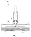
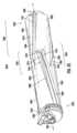
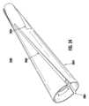
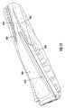
ここで図1~図5を参照すると、ノズル100の一つの実施形態が概して図示される。本明細書で使用される場合、掃除機ノズルという用語は、任意のタイプの掃除機ノズルを指すのであり、またクリーニングヘッド、クリーニングノズル、または単にノズルと呼んでもよい。こうしたノズルは、手動の掃除機およびロボット掃除機を含むが、これらに限定されない、掃除機(または任意の他の表面クリーニング装置)に取り付けられてもよい。手動の掃除機のさらなる非限定的な例としては、縦型掃除機、キャニスター掃除機、スティック掃除機、およびセントラルバキュームシステムが挙げられる。それ故に、本開示の様々な態様は、手動の掃除機またはロボット掃除機の文脈で図示および/または記述されてもよいが、当然のことながら、特に別段の記載がない限り、本明細書に開示される特徴は、手動の掃除機、ロボット掃除機、および他の同様の表面クリーニング装置に適用可能である。1-5, one embodiment of a
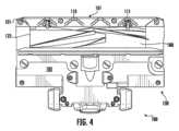
これを念頭に置いて、図1は概して、ノズル100の等角図を図示する。図2は概して、図1のノズル100の正面図を図示する。図3は概して、図1のノズル100の側面図を図示する。図4は概して、図1の底部クリーナーノズル100の側面図を図示する。図5は概して、図1の底部斜視クリーナーノズル100の側面図を図示する。With this in mind, FIG. 1 generally illustrates an isometric view of the
当然のことながら、図1~図5に示すノズル100は、例示的な目的のみのためであり、本開示と一致する掃除機は、図1~図5に示すすべての特徴を含んでいなくてもよく、かつ/または図1~図5に示されていない追加的な特徴を含んでいてもよい。It should be understood that the
示すように、ノズル100は、一つ以上のアジテータチャンバ122を少なくとも部分的に画定する/含む、本体またはハウジング130を含む。アジテータチャンバ122は、ハウジング130の底部表面/プレート105の一部分の中に、および/または一部分によって画定される、一つ以上の開口部(または空気入口)を含む。少なくとも一つの回転アジテータまたはブラシロール180は、ノズル100(永久的にまたは取り外し可能にそれに連結される)に連結されるように構成され、一つ以上の回転システムによってアジテータチャンバ122内のピボット軸を中心として回転するように構成される。回転システムは、掃除機ヘッド100内に少なくとも部分的に配置されてもよく、またアジテータ180を回転させるための一つ以上のベルトおよび/またはギアトレインに連結された一つ以上のモータ、例えば、ACモータおよび/またはDCモータを含んでもよい。As shown, the
ノズル100は、破片収集チャンバ(図示せず)に連結され、これによりそれはアジテータチャンバ122と流体連通して、回転アジテータ180によって収集された破片を引き込み、かつ貯蔵する。アジテータチャンバ122および破片チャンバは、アジテータチャンバ122および破片収集チャンバ内の空気流(例えば、部分真空)を生成して、それによってアジテータチャンバ122および/またはアジテータ180に近接する破片を吸引するために、真空源(例えば、吸引モータまたはそれに類するもの)に流体連結される。The
アジテータ180の回転は、クリーニング表面から破片を攪拌/ほぐすように動作する。随意に、一つ以上のフィルタは、真空空気流内に同伴された破片(例えば、ダスト粒子またはそれに類するものなどの超微細な破片)を除去するために、ノズル100内(または掃除機の他の好適な場所)に配置されてもよい。Rotation of the
破片チャンバ、真空源、および/またはフィルタは、少なくとも部分的にノズル100内に位置してもよい。さらに、破片チャンバ、真空源、および/またはフィルタをノズル100へと流体連結するために、一つ以上の吸引チューブ、ダクト、またはそれに類するもの136が提供されてもよい。ノズル100は、回転システムおよび/または真空源などの、しかしこれらに限定されないノズル100の様々な構成要素に電力を提供するために、電気コード/プラグ、電池(例えば、充電可能電池および/または非充電可能電池)、および/または回路(例えば、AC/DCコンバータ、電圧レギュレータ、昇圧/降圧トランス、またはそれに類するもの)などの、しかしこれらに限定されない、一つ以上の電力供給源を含んでもよく、かつ/またはそれらに電気的に連結されるように構成されてもよい。The debris chamber, vacuum source, and/or filter may be located at least partially within the
ハウジング130は、上部表面102および前縁(または先縁部)101をさらに含む。空気は、前縁101を通り過ぎ、そしてアジテータチャンバ122の中へと流れる。凹部またはキャスタレーション110が、ノズル100の前縁101に沿って提供される。キャスタレーション110は、ノズル100内の共有吸引チャネルへと移行する、複数の入口および関連付けられた入口経路を提供する。The
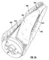
図4~図5により明確に示されるように、キャスタレーション110は、ハウジングの基部プレート105から離れるように延在する複数の突起部によって画定される。各突起部は、その先端がノズル100の先縁部101に隣接して配置される、実質的に収束する(例えば、二つまたは三つの側面を含んでもよい三角形/矢じり型、しかしこれらに限定されない)プロファイルを含む。それ故に、各突起部は、互いに向かって延在する少なくとも部分的に二つの勾配のあるエッジによって少なくとも部分的に画定されてもよく、また先縁部101に対して実質的に横断してもよく、これにより二つの勾配のあるエッジは、先縁部101に隣接する頂点/点で交わる。勾配エッジのうちの一つ以上は、線形および/または非線形であってもよい。隣接する突起部は、ノズル100の中心に向かって、かつ重要なことに、その汚れた空気入口に向かってテーパ状になっている空気入口を集合的に画定する。したがって、各空気入口は、ノズルの中心に隣接する第二の幅W2に移行する、ノズルの先縁部101に隣接する第一の幅W1を有するテーパ状になっているプロファイルを含み、第一の幅W1は、第二の幅W2より大きい。したがって、キャスタレーション110はまた、面取りしたプロファイルを有する、または面取りしたキャスタレーションであると呼んでもよい。下記でさらに考察するように、隣接するキャスタレーション間の距離およびキャスタレーション特性(寸法および表面角度など)は、標的の破片、例えば、チェリオスのための望ましい空気流/吸引およびクリアランスプロファイルを達成するように選択することができる。As more clearly shown in FIGS. 4-5, the
続いて、面取りしたキャスタレーション110は、ノズル100の先縁部101に沿って提供され、破片が前縁101を通って吸引チャネルへと通過し、最終的に、表面処理装置の前方ストロークおよび後方ストローク中に主本体の中へと入ることを可能にする。図4~図5にさらに示すように、面取りしたキャスタレーション110は、ホイール受容部/空洞を有する突起部を提供することができる。ホイール、例えば、ホイール111は、その後、ホイール受容部へと連結され、その上に閉じ込められてもよい。キャスタレーション110によって提供されるホイール111および関連付けられた受容部は、有利なことに、例えば、上述のように、エッジクリーニングの改善を可能にするために、ノズル100の側面から離れてオフセットされた、ノズル100内の位置においてホイール111を配置することを可能にする。さらに、面取りしたキャスタレーション110の受容部内のホイール111の配置は、空気流を制限する可能性を最小化するか、または別の方法で低減する。The chamfered
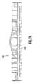
図6A~図11Bは、本開示の実施形態と一致する、ノズルの底部フレーム200の例示の実施形態を図示する。底部フレーム200は、面取りしたキャスタレーション210を含む。面取りしたキャスタレーション210は、底部フレーム200の先縁部に配設され、下側平面219から床表面に向かって突出する。上述のように、キャスタレーションは、例えば、ホイール211を受容および連結するためのホイール受容部を画定することができる。6A-11B illustrate an example embodiment of a
本開示は、キャスタレーション210の複数の要因は組み合わせで機能するのであり、望ましい機能および空気流/吸引を達成するように選択することができることを、特定した。The present disclosure identifies that multiple factors of the
図12~図15は、本開示の実施形態と一致する、面取りしたキャスタレーション1100の例示の寸法を示す。本開示の一つの目的は、空気流/吸引を最大化する必要性と、比較的大きい破片がキャスタレーション110を通してノズルに入ることを可能にする能力とのバランスをとることである。これを念頭に置いて、本開示は、キャスタレーション1100間の間隔(またはオフセット距離)が、ブラシロールチャンバの中へと入ることができる破片の全体的なサイズ/寸法を少なくとも部分的に決定することを特定した。キャスタレーションの間隔は、ほぼチェリオスのサイズの物体がキャスタレーションを通過することを可能にする、事前定義された均一なオフセット距離へと設定されることが好ましい。12-15 show example dimensions of
続いて、キャスタレーション1100は、動作中に床に最も近いノズルの面1104から突出する。各キャスタレーション1100は、動作中に床表面と接触または隣接する底部表面1105を有する。キャスタレーション1100の全体的な高さ1103は、ノズルの面1104からキャスタレーション1100の底部表面1105までの距離である。キャスタレーション高さ1103は、ノズルに対する望ましい最低地上高に基づいて部分的に決定される。最低地上高は、例えば、キャスタレーション1100の下を通過することができる破片の最大サイズにさらに影響を与えるのであり、仕切りを超える移行に影響を与えることができる。The
任意の個別のキャスタレーション1100の水平寸法またはキャスタレーション幅1107は、キャスタレーション1100がどの程度面積を制限するかを決定する一つの要因である。キャスタレーション幅1107は、例えば、ノズル入口の開口部幅および各キャスタレーション1100間の間隔に基づいて決定することができる。より幅広いキャスタレーション1100は、一般的にノズルの表面積被覆率を増加させる。キャスタレーション1100の幅1107の増加によって生じるノズルの表面積被覆率は、ノズル入口におけるより狭い開口部を作り出す。これらのより狭い開口部は、動作中にノズルを通る、より高い空気速度を引き起こす。The horizontal dimension or
キャスタレーション奥行1108は、キャスタレーション1100がノズルの前縁からブラシロールチャンバに向かってどの程度後方に延在するかの寸法である。
キャスタレーション1100の前方の「外殻」の角度、すなわち外殻角度(Φ)1110は、キャスタレーション1100の前方がその二つの縁の間になす角度である。外殻角度1110は、キャスタレーション1100と接触した後、どの程度速く大きい破片がブラシロールチャンバの中へと摺動することができるかに影響を与える。より小さな角度1110では、キャスタレーション1100は概して平坦なブレードを模倣するのであり、大きい破片はノズルの先縁部1112を通り抜けブラシロールチャンバ内に容易に通過することができる。しかしながら、より大きい角度1110は、通常、大きい破片が、ブラシロールチャンバに入る時に、より大きい抵抗に直面することを意味する。一般的に、より大きい外殻角度1110は、前方入口を、より多くの大きい破片が蓄積および詰まらせることにつながる。より小さい外殻角度1110は、より広い幅1107を有するキャスタレーション1100では、実用的でもなく望ましいものでもない場合がある。 The
The angle of the front "shell" of the
図16Aに示すように、より高い空気速度は、傾斜部からより速く大きい破片を排出することを支援し、これは詰まりの可能性を防止または低減するため、キャスタレーション幅が大きい場合、より大きな外殻角度が許容可能な場合がある。As shown in FIG. 16A, a larger shell angle may be acceptable when the castellation width is large, since higher air velocity helps to eject larger debris faster from the ramp, which prevents or reduces the possibility of clogging.
キャスタレーションを摺動して下る時にチェリオスの吸引または転がる動きがないと仮定すると、キャスタレーションを下るその加速度は、以下のように概算することができる。Assuming there is no suction or rolling motion of the Cheerios as they slide down the castellations, their acceleration down the castellations can be roughly estimated as follows:
図16Bは、外殻角度と、模範的な大きい破片の加速との間の関係を図示する。線の色がより薄い領域1601(90~130度)は、面取りしたキャスタレーションをモデリングする時の外殻角度の通常の範囲を表す。この領域1601では、加速は、外殻角度の角度の増加ごとに平均2.8%減少し、外殻角度が大きくなるにつれて1度あたりより多く減少する。より低い加速は、破片(例えば、チェリオス)を、ブラシロールチャンバの中へとよりゆっくりと排出し、より多くの詰まりおよび破片のピックアップの失敗につながることを引き起こす。Figure 16B illustrates the relationship between shell angle and acceleration of an exemplary large debris. The lighter line area 1601 (90-130 degrees) represents the typical range of shell angles when modeling chamfered castellations. In this region 1601, acceleration decreases by an average of 2.8% per degree increase in shell angle, and decreases more per degree as the shell angle increases. The lower acceleration causes the debris (e.g., Cheerios) to exit more slowly into the brush roll chamber, leading to more clogging and failure to pick up the debris.
本開示では、キャスタレーション1100は、少なくとも一つの面取り1120(例えば、図12を参照のこと)によってさらに特徴付けられる。面取り1120は、キャスタレーション1100の一部分を除去することによって作り出す/形成することができ、その寸法は、その後、上述のように公称吸引およびクリアランスを達成するために選ばれる。In the present disclosure, the
面取り1120は、垂直面から切り取られた傾斜をつけた縁によって形成されてもよい。図12で見られるように、キャスタレーション1100の後部と同一平面上の面取り1120は、底部1105における間隔を概して広くする一方で、上部1104において、より余裕の少ない間隔を保つ。これは、キャスタレーション1100によって制限される全体的な表面積を増加させ、かつ空気速度を増加させる一方で、重要なことに、依然としてより大きい破片の通過を可能にする。The
面取り1120の主な寸法は、その水平寸法(x)1102および垂直寸法(y)1101である。これらの寸法1102、1101は、ブラシロールチャンバへと通り抜けることができる破片のサイズおよびタイプを決定するのに役立つ。The main dimensions of the
上述のように、キャスタレーション1100の寸法は、任意の可能性のある面取り1120の可能な寸法1102、1101に影響を与える。
押出角(α)1106(例えば、図13を参照のこと)は、キャスタレーション1100が水平に対してなす角度である(側面図)。押出角1106は、面取り1120のx成分およびy成分の両方に影響を及ぼす。 As discussed above, the dimensions of the
The extrusion angle (α) 1106 (see, e.g., FIG. 13) is the angle that the
半径(R)1109(例えば、図14を参照のこと)は、キャスタレーション1100上の前方の丸みの半径であり、主に面取りのx成分に影響を及ぼす。半径1109は、主に面取りのx成分に影響を及ぼす。Radius (R) 1109 (see, e.g., FIG. 14) is the radius of the anterior radius on the
キャスタレーション高さ1103(例えば、図12を参照のこと)は、面取り1120のx成分およびy成分の両方に影響を及ぼす。
キャスタレーション幅1107は、主に面取り1120のx成分に影響を及ぼす。 The castellation height 1103 (see, for example, FIG. 12) affects both the x and y components of the
The
キャスタレーション奥行1108は、主に面取り1120のx成分に影響を及ぼす。
外殻角度1110は、主に面取り1120のx成分に影響を及ぼす。
オフセット(O)1111(例えば、図12および図14を参照のこと)は、キャスタレーションの角度が付けられた壁がプレートの前方に向かって移される距離である。 The
The
The offset (O) 1111 (see, for example, Figures 12 and 14) is the distance that the angled wall of the castellation is shifted toward the front of the plate.
標準的なキャスタレーションでは、キャスタレーション間の間隔の決定は単純であり、吸引ノズルを通過する必要がある破片のサイズなどの要因に基づくことができる。
例えば、ピックアップされる破片の最大寸法が13.95mmである場合、面取りのないキャスタレーションでは、約13.95mmの最小間隔が必要とされる。さらに、試験は、2mmの追加的なクリアランスが、吸気ノズルでの詰まりを低減することを示唆している。試験およびシミュレーションは、追加的なクリアランス空間は、ノズルでの破片の詰まりをさらに低減はせず、ノズルを通る空気速度を低下させることを示している。したがって、各キャスタレーション間の16mm+-2mmの空間は、標的破片サイズの詰まりのない通過を可能にする一方で、キャスタレーションからの空気速度の増加からの利益も受ける。 For standard castellations, determining the spacing between castellations is simple and can be based on factors such as the size of the debris that needs to pass through the suction nozzle.
For example, if the maximum dimension of debris to be picked up is 13.95 mm, then a minimum spacing of approximately 13.95 mm is required for castellations without chamfers. Furthermore, testing suggests that an additional 2 mm of clearance reduces clogging at the intake nozzle. Testing and simulations indicate that the additional clearance space does not further reduce debris clogging at the nozzle, but reduces the air velocity through the nozzle. Thus, a space of 16 mm +- 2 mm between each castellation allows for unclogging passage of the target debris size while also benefiting from increased air velocity from the castellation.
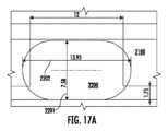
図17Aおよび図17Bは、ノズルが大きい破片に遭遇する際のキャスタレーションを有するノズルを図示する概略線図である。図17Aは、一つ以上の面取りを有しない標準的なキャスタレーション2100を図示する。図17Bは、面取りしたキャスタレーション2110を図示する。大きい破片2200、例えば、チェリオスは、図17Aに示されるキャスタレーション2100を通過することができないが、同じ寸法の破片は、面取り2111によって提供される間隔の増加のために、図17Bの面取りしたキャスタレーション2110を通過することができる。FIGS. 17A and 17B are schematic diagrams illustrating a nozzle with castellations as the nozzle encounters large debris. FIG. 17A illustrates a
図17Aは、面取りがなく、かつ12mmの間隔のキャスタレーション2100を示す。例示の大きい破片2200は、7.58mmの高さ2201、および13.95mmの外径2202を有する。Figure 17A shows
図17Bは、4mm×4.75mmの面取り2111を有する12mmの間隔を有するキャスタレーション2110を示す。面取り2111のx寸法は、間隔を底部において20mmまで延長する。しかしながら、面取り2111の使用は、20mmの間隔を有する面取りがないものとは対照的に、間隔当たり29mm2の入口面積を保持する。それ故に、より大きい破片は、20mmの間隔を有するキャスタレーションによって引き起こされる空気速度の減少を伴わずにピックアップされる。 17B shows
ピックアップされる破片のサイズが、標準的なキャスタレーションに対する間隔を決定するために使用されるのとまさに同じように、破片の寸法2201、2202を使用して、面取り2111の寸法成分を決定することができる。幅2202に加えて、面取り2111の垂直成分を計算するために、破片の高さ2201を使用してもよい。所望の高さが計算された後、以下の式を使用して、面取りの当初のy成分を決定してもよい。Just as the size of the picked up pieces is used to determine the spacing for a standard castellation, the
y=高さ-最低地上高 式(2)
面取りのx成分は、面取りの中間点に面取りを有することなく、望ましい間隔を作り出すように、好ましくは選択されるべきである。それ故に、キャスタレーションに対する当初の所望の間隔は、空間の真ん中に位置する。例えば、上述のように、面取りを有しないで間隔を決定する時、13.95mmの外側寸法を有する破片を100%ピックアップするために、16mm間隔を使用した。 y = height - ground clearance Equation (2)
The x-component of the chamfer should preferably be selected to produce the desired spacing without having a chamfer at the midpoint of the chamfer. Therefore, the initial desired spacing for the castellations is located in the middle of the space. For example, as described above, when determining spacing without a chamfer, a 16 mm spacing was used to obtain 100% pickup of pieces having an outer dimension of 13.95 mm.
図18に図示するように、線が、面取りの斜辺の中間点において、二つのキャスタレーションの面取りの間で延長される場合、この値は、面取りの使用を伴わずに当初計算されたどのような公称間隔にも、等しくなるべきである。本実施形態では、4mm×4.75mmの面取りは、12mm幅の間隔の上部に使用されて、面取りの中間点において16mmの間隔を作り出す。As shown in FIG. 18, if a line is extended between the two castellation chamfers at the midpoint of the chamfer's hypotenuse, this value should be equal to whatever nominal spacing was originally calculated without the use of the chamfer. In this embodiment, a 4mm by 4.75mm chamfer is used on top of a 12mm wide spacing to create a 16mm spacing at the midpoint of the chamfer.
吸引ノズルに対するキャスタレーションの要件が決定されると、以下の寸法を決定することができる。
面取り寸法:xおよびy
キャスタレーション高さ:H(通常、吸引ノズルの要件に基づいて決定される)
押出角:α(当初の計算には45°を使用してもよいが、望ましい半径を達成するために増加または減少させることができる)
キャスタレーション奥行:D(吸引ノズルの要件に基づいて決定される)
キャスタレーション幅:W(前方入口の幅、間隔、およびキャスタレーションの数から決定される)
上記の寸法を使用して、以下の測定値が、面取りしたキャスタレーションに対して計算されてもよい。オフセット(O)、押出長さ(E)、外殻角度(Φ)、および半径(R)。 Once the castellation requirements for the suction nozzle have been determined, the following dimensions can be determined:
Chamfer dimensions: x and y
Castellation height: H (usually determined based on the requirements of the suction nozzle)
Extrusion angle: α (45° may be used for initial calculations, but can be increased or decreased to achieve the desired radius)
Castellation depth: D (determined based on the requirements of the suction nozzle)
Castellation width: W (determined from the width of the front entrance, spacing, and number of castellations)
Using the above dimensions, the following measurements may be calculated for the chamfered castellation: offset (O), extrusion length (E), shell angle (Φ), and radius (R).
図19A~図19Dに見られるように、一部の実施形態は、一つ以上の面取りしたキャスタレーション1902内、例えば前述のホイール受容部/空洞内に定置された一つ以上のホイール1901をさらに含み、これによりホイール1901はノズルの側面から離れて位置する。それ故に、キャスタレーションの寸法は、ホイールを含むことを可能にする必要がある。As seen in Figures 19A-19D, some embodiments further include one or
掃除機の動作中に、吸引入口の前方にあるホイール1901は破片へと曝露される。破片によるホイールの詰まりを防止するために、吸引ノズルの先縁部は、一つ以上のホイール1901(例えば、一つ以上のホイール1901の先縁部)を完全に封入する/囲むことが好ましい。一つ以上のホイール1901が吸引ノズルの横方向側面上に位置する場合、ホイールの筐体は、吸引ノズルによって側面キャスタレーション1903に対する形状の範囲を制約する。さらに、側面キャスタレーション1903は、取り付け点などの他のハードウェアを収容することを必要とする場合があり、一つ以上のホイール1901のためには比較的小さい量の余地しか残らない。本実施形態では、側面キャスタレーション1903は、必ずしもホイールを収容する必要なく、改善されたエッジクリーニングを可能にする。During operation of the vacuum cleaner, the
図20A~図20Bに示すように、図19A~図19Dに示す一つ以上のホイールは、キャンバー付きホイールであってもよい。キャンバーは、ホイールが床に対して立つ角度である。本実施形態では、ホイールは、各ホイールの上部が、動いていない時に吸引ノズルの中心のより近くに傾く、静止した負のキャンバーを有する。キャンバー角は、特定のサスペンション設計の操縦性を変化させ、特に、負のキャンバーは、動いている間のグリップを改善する。一般的に、各ホイールは独立して動作し、かつ円弧の状態で転がる。両方のホイールが対称的な負のキャンバーを有する場合、横方向の力は実質的に互いに相殺する。それ故に、ユーザは、動作中にクリーニング装置を容易に操縦することができ、「グリップ」が増加することにより、制御の知覚が改善される。As shown in Figures 20A-20B, one or more of the wheels shown in Figures 19A-19D may be cambered wheels. Camber is the angle at which the wheel stands relative to the floor. In this embodiment, the wheels have a static negative camber, where the top of each wheel is tilted closer to the center of the suction nozzle when not moving. The camber angle changes the maneuverability of a particular suspension design, and in particular, negative camber improves grip while moving. Generally, each wheel operates independently and rolls in an arc. When both wheels have symmetric negative camber, the lateral forces substantially cancel each other out. Therefore, the user can easily steer the cleaning device during operation, and the increased "grip" improves the perception of control.
制御の知覚に加えて、掃除機の動作中に生成するノイズは、ユーザ体験に著しい影響を与える可能性がある。ノイズの増加、特に吸引モータと関連付けられないノイズは、否定的な品質および望ましくない品質と見られる。ホイールのチャタリング、すなわち動作中に掃除機のホイールによって作り出されるノイズは、可能な限り低減されるべきである。本実施形態のキャンバー付きホイールは、動作中のホイールのチャタリングの減少を可能にする。In addition to the perception of control, the noise a vacuum cleaner produces during operation can significantly impact the user experience. Increased noise, especially noise not associated with the suction motor, is seen as a negative and undesirable quality. Wheel chatter, i.e. the noise produced by the vacuum cleaner's wheels during operation, should be reduced as much as possible. The cambered wheels of this embodiment allow for reduced wheel chatter during operation.
キャンバー付きホイールは、移動方向に実質的に垂直な力を生成する。この力により、キャンバー付きホイールがノズル上のホイールハウジング内に押し込まれることになる。ホイールのチャタリングノイズの原因のうちの一つは、ハウジングに対するホイールのノッキングであるので、キャンバー付きホイールは、ハウジングに対するホイールの動きの範囲を制限する。The cambered wheel generates a force substantially perpendicular to the direction of travel. This force pushes the cambered wheel into the wheel housing over the nozzle. Since one of the causes of wheel chatter noise is the wheel knocking against the housing, the cambered wheel limits the range of motion of the wheel relative to the housing.
ここで図21を参照すると、本開示と一致する一つ以上のキャスタレーション2110を含むノズル2100の別の実施例が概して図示されている。本明細書に記述するように、キャスタレーション2110は、実質的に収束する(例えば、二つまたは三つの側面を含んでもよい三角形/矢じり型、しかしこれらに限定されない)プロファイルを含んでもよく、その先端2115はノズル2100の先縁部2101に隣接して配置される。キャスタレーション/突起部2110は、互いに向かって延在する少なくとも部分的に二つの勾配のあるエッジ/壁2113、2114によって少なくとも部分的に画定されてもよく、また先縁部2101に対して実質的に横断方向であってもよく、これにより二つの勾配のあるエッジ/壁2113/2114は、先縁部2101に隣接する頂点/点/先端2115で交わる。勾配エッジ/壁2113、2114のうちの一つ以上は、線形および/または非線形であってもよい。キャスタレーション/突起部2110のうちの一つ以上は、中空後部を有すると考えられてもよい。本明細書で使用される場合、「中空後部」という用語は、キャスタレーション2110が、二つの勾配のあるエッジ/壁2113、2114の遠位端2117、2119(例えば、二つの勾配のあるエッジ/壁2113、2114の、概して頂点/点2115の反対側の、端2117、2119)を連結/接続する部分を含まないことを意味することが意図される。このように、中空後部キャスタレーション2110は、二つの勾配のあるエッジ/壁2113、2114の遠位端を連結/接続する後部壁を有しない。したがって、中空後部キャスタレーション2110およびハウジング2120(例えば、ソールプレート2121)は、攪拌チャンバ122の中への空気流に曝露される(例えば、直接的に流体連結される)、凹部および/または空洞2122を画定する場合がある。21, another embodiment of a
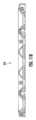
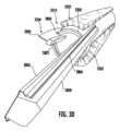
ここで図22を参照すると、一つ以上のアジテータ2210を含むノズル2200の別の実施例が一般的に示されており、これは図4のアジテータ180の実施例であってもよい。アジテータ2210は、概して本明細書に記載されるように、ハウジング/本体130内に形成された一つ以上の攪拌チャンバ122内に回転可能に配置されてもよい。図23を参照すると、アジテータ2210は、ノズル2200から取り外されて示される。アジテータ2210は、アジテータ2210のピボット軸PA(図22)に沿って延在する長い軸2301を有する細長い本体またはコア2300を含んでもよい。細長い本体またはコア2300は、アジテータ2210をアジテータチャンバ122内で回転させるのを可能にするように構成された実質的に剛直な材料から形成されてもよい。細長い本体またはコア2300は、概して円筒状の形状(例えば、図24を参照のこと)を有してもよく、または2019年10月18日に出願された米国特許出願第16/656,930号(参照により本明細書に完全に組み込まれる)に記述されるテーパ状になっている設計を有してもよい。見ることができるように、アジテータ2210は、少なくとも一つの軟質のクリーニング特徴部2302と、少なくとも一つのチャネル内に配置され、アジテータ2210の長手方向軸2806に沿った方向で、アジテータ2210の細長い主本体2300の少なくとも一部分の周りにらせん状に、かつ当該少なくとも一部分から半径方向外向きに延在する、少なくとも一つの弾性的に変形可能なフラップ2304(側壁の実施例である場合がある)とを含む。本明細書に記述されるように、アジテータ2210は一般的に、少なくとも一つのチャネルおよびその中に配置された少なくとも一つの弾性的に変形可能なフラップを形成する軟質材料を有する、毛羽立ったローラーと考えられてもよい。22, another embodiment of a
軟質のクリーニング特徴部2302は、比較的可撓性のフィラメント/材料から形成された、プラシ天のような高密度のパイル地(例えば、ベルベットまたはベルベット様材料、しかしこれらに限定されない)を含んでもよい。パイル地は、カーペット、ラグ、または布の隆起したまたはふわふわした表面と同様であってもよく、例えば、接着剤を使用して、細長い主本体2300へと取り付けられた生地キャリア部材(図示せず)上に織られたフィラメントを備える。パイル地のフィラメントの長さは、5~15mmの範囲内であってもよい。生地キャリアは、パイル地が実質的に連続的に、本明細書に記述されるように細長い主本体2300の外表面を実質的に覆うように、細長い主本体2300上に巻かれた細片の形態であってもよい。別の方法として、キャリア部材は、細長い主本体2300がその中へと挿入される円筒状のスリーブの形態であってもよい。The
パイル地材料は、ナイロン、ポリエステル、石油系アクリルもしくはアクリロニトリルなどの合成繊維、天然繊維(ウールまたは動物の毛皮など)、または木材パルプ系レーヨンを含んでもよく、かつ/またはブレンド繊維由来であってもよい。軟質のクリーニング特徴部2302の毛羽またはパイル地は、破片を攪拌および/またはノズル2200の開口部に向かって輸送するように構成されてもよい。パイル地/毛羽の軟質に起因して、軟質のクリーニング特徴部2302は、振動を減衰させ、音を吸収し、かつ/または床表面(例えば、ハードウッドの床またはそれに類するもの、しかしこれらに限定されない)に対する損傷(例えば、引っ掻き傷)を低減する場合がある。非限定的な実施例として、軟質のクリーニング特徴部2302は、5000~8250グラム/cm、例えば、6600グラム/cmの密度を有してもよい。軟質のクリーニング特徴部2302のパイル地は、細長い本体またはコア2300から約2~10cm、例えば7mm、延在してもよい。The pile material may include synthetic fibers such as nylon, polyester, petroleum-based acrylic or acrylonitrile, natural fibers (such as wool or animal fur), or wood pulp-based rayon, and/or may be derived from blended fibers. The fluff or pile of the
アジテータ2210は、少なくとも一つの弾性的に変形可能なフラップ2304が少なくとも部分的にその中に配置される、一つ以上のチャネル2310を含んでもよい。チャネル2310は、アジテータ2210が回転するにつれて弾性的に変形可能なフラップ2304が前向きおよび後向きに動くことを可能にするように構成されてもよい。少なくとも一つの実施例では、チャネル2310は、約6~12mm、例えば約8mmの幅(前方から後方へと)の開口部に近接した幅を有してもよい。The
チャネル2310は、軟質のクリーニング特徴部2302によって少なくとも部分的に形成されてもよく、かつ/または画定されてもよい。少なくとも一つの実施例(例えば、図25~図27を参照のこと)では、チャネル2310は、基部2312(細長い主本体2300によって形成されてもよい)および二つの側壁2314、2316(軟質のクリーニング特徴部2302によって形成されてもよい)を含む、「U」断面形状を有してもよい。側壁2314、2316は、細長い主本体2300の表面に対して実質的に垂直であってもよく、かつ/または細長い主本体2300の表面に対して鈍角および/もしくは鋭角で延在してもよい。別の方法として(または追加的に)、チャネル2310は、二つの側壁2314、2316が弾性的に変形可能なフラップ2304の基部領域から延在する、「V」断面形状を有してもよい。The
一つ以上のチャネル2310は、アジテータ2210の端または端領域2320、2322のうちの一つから、概してアジテータ2210の中央領域2324に向かって延在してもよい。少なくとも一つの実施例では、チャネル2310は、端または端領域2320、2322から延在し、中央領域2324で終結する。このように、チャネル2310の各々の長さは、主本体2300の長さ未満の長さがある。各端2320、2322からのチャネル2310の部分2326は、アジテータがピボット軸を中心として回転するにつれて、中央領域2324内で互いに長手方向に重複してもよい(すなわち、チャネル2310の部分2326は、アジテータ2310が回転するにつれて、同じ床のエリアと接触してもよい)。チャネル2310は、アジテータ2310にわたって直線的および/または非直線的に延在してもよい。One or
少なくとも一つの実施例では、軟質のクリーニング特徴部2302(例えば、毛羽)は、細長い主本体2300の円筒状部分の表面のかなりの部分(すなわち、円形の端以外の細長い主本体2300の部分)にわたって延在してもよい。本明細書で使用される場合、細長い主本体2300の円筒状部分の表面のかなりの部分とは、細長い主本体2300の円筒状部分の表面の少なくとも75%、例えば、細長い主本体2300の円筒状部分の表面の少なくとも80%、細長い主本体2300の円筒状部分の表面の少なくとも85%、および/または細長い主本体2300の円筒状部分の表面の少なくとも90%を意味することが意図され、その中のすべての値および範囲を含む。軟質のクリーニング特徴部2302は、チャネル2310が位置する場所を除いて、細長い主本体2300の円筒状部分の表面全体にわたって延在してもよい。In at least one embodiment, the soft cleaning feature 2302 (e.g., fluff) may extend over a substantial portion of the surface of the cylindrical portion of the elongated main body 2300 (i.e., the portion of the elongated
軟質のクリーニング特徴部2302は、材料の単一の単片から形成されてもよい。別の方法として、軟質のクリーニング特徴部2302は、細長い主本体2300へと連結された複数の別個の部品から形成されてもよい。複数の別個の部品から形成される軟質のクリーニング特徴部2302を形成することは、アジテータ2210の製造、特にチャネル2310の形成を補助する場合がある。The
本明細書で述べたように、アジテータ2210は、複数の変形可能なフラップ2304を含んでもよく、変形可能なフラップ2304の各々の長さは、主本体2300の長さ未満の長さがある。示すように、アジテータ2210は、アジテータ220および/または主本体2300の端領域2320、2322からアジテータ220および/または主本体2300の中央領域2324へと延在する複数の変形可能なフラップ2304を含む。本明細書で考察するように、アジテータ2210はいかなる剛毛も含まなくてもよいが、当然のことながらアジテータ2800は、フラップ2304に加えて(またはフラップ2304を有しないで)剛毛を随意に含んでもよい(例えば、剛毛は、実質的にフラップ2304に隣接する)。As discussed herein, the
図23に戻ると、フラップ2304は、細長い主本体2300の少なくとも一部分の周りに概してらせん状に延在してもよく、また弾性的に変形可能な材料で形成されてもよい。フラップ2304の端領域3200、3202のうちの一つ以上は、面取りまたはテーパを含んでもよい(例えば、フラップ2304は、唯一のまたは各々の端領域3200、3202においてテーパを含んでもよい)。このように、端領域3200、3202の少なくとも一部分におけるフラップ2304の高さは、中央領域3206におけるフラップ2304の高さ3204未満であってもよい。言い換えれば、テーパは、フラップ2304のクリーニングエッジ3201を細長い主本体2300に近づけさせてもよい。一実施例によれば、フラップ2304の高さは、フラップ2304の基部3208からフラップ2304のクリーニングエッジ3201まで測定されてもよく、基部3208はアジテータ2210(例えば、細長い主本体2300)へと固定されるように構成される。別の方法として、フラップ2304の高さは、アジテータ2210の回転軸からフラップ2304のクリーニングエッジ3201まで測定されてもよい。端領域3200、3202のテーパは、一定(例えば、直線)および/または非直線であってもよい。少なくとも一つの実施例では、フラップ2304の真ん中は、最大の高さを有してもよい。第一の端領域3200のテーパは、第二の端領域3202のテーパと同じであってもよく、または異なっていてもよい。Returning to FIG. 23, the
第一の端領域3200は、細長い主本体2300の端領域のうちの一つの中に配設されてもよく、また第二の端領域3202は、細長い主本体2300の中央領域2324の中に配設されてもよい。第一の端領域3200のテーパは、端キャップ、例えば、2019年10月18日に出願された米国特許出願第16/656,930号(参照により本明細書に完全に組み込まれる)に記載される端キャップなどの移動毛髪端キャップ内に少なくとも部分的に受容されるように構成されてもよい。第一の端領域3200のテーパは、フラップ2304と端キャップとの間の摩耗および/または摩擦を低減してもよく、それによってフラップ2304および端キャップの寿命を延ばす場合がある。少なくとも一部の実施例では、第一の端領域3200のテーパは、フラップ2304が端キャップ内で回転するので、フラップ2304の折り重ね(端キャップ内と、端キャップの近位および外側に配置されたフラップ2304の部分との両方)を低減する場合がある。フラップ2304の折り重ねを低減することは、フラップ2304とクリーニングされる表面との間の接触を増加させる場合があり、それによってクリーニング性能を増強する場合がある。The
第一の端領域3200のテーパは、長さおよび高さを有してもよい。長さは、それが受容される端キャップの寸法に基づいて選択されてもよい。例えば、長さは、端キャップ内のフラップ2304の挿入距離と同じであってもよく、端キャップ内のフラップ2304の挿入距離より短くてもよく、または端キャップ内のフラップ2304の挿入距離より長くてもよい。第一の端領域3200のテーパは、フラップ2304が端キャップの中へと押し込まれる際に、フラップ2304の曲がりを緩和するのに役立つ。例として、第一の端領域3200のテーパは、5~9mmの長さ、および1~3mmの高さ、ならびに/または7mmの長さ、および2mmの高さを有してもよい。The taper of the
第二の端領域3202のテーパは、アジテータ2210に沿った毛髪の移動を強化するように構成されてもよい。特に、テーパは、毛髪は最小直径へと移動する傾向があるので、毛髪の移動を増強する場合がある。それ故に、第二の端領域3202のテーパは、毛髪を特定の場所に向かってより効果的に移行することを可能にする場合がある。加えて、第二の端領域3202のテーパは、毛髪貯蔵エリアとして機能する場合がある。この目的のために、アジテータ2800の中央領域2324は、近接端領域3000、3002の全体的な直径と比較して、より小さい全体的な直径を有してもよい。このように、毛髪は、アジテータ2310の中央領域2324の周りに蓄積し、かつ巻き付く場合がある。第一のフラップ2304の第二の端領域3202のテーパは、中央領域2324内の隣接するフラップ2304の、第二の端領域3202のテーパと部分的に重複し得る。2019年10月18日に出願された米国特許出願第16/656,930号(参照により本明細書に完全に組み込まれる)に記述されるように、フラップ2304がデブリダーユニットおよび/またはリブと組み合わせて随意に使用される時、デブリダーユニットの歯および/またはリブは、フラップ2304の第二の端領域3202に近接する領域において随意により長くてもよい。The taper of the
フラップ2304のテーパの寸法は、フラップ2304の性能および/または寿命に影響を与えることができる。テーパ(例えば、長さおよび/または高さ)を増加することは、毛髪の移動を改善することができるが、大きすぎるテーパは、クリーニング性能に悪影響を及ぼす可能性がある。例えば、大きすぎる第二の端領域3202のテーパは、ギャップをもたらす可能性があり、フラップ2304はクリーニングされる表面と十分に接触しない。一方で、第二の端領域3202(例えば、長さおよび/または高さ)の小さすぎるテーパは、十分な毛髪の移動をもたらさない場合がある。The dimensions of the taper of the
実験は、内側面取りを除去する(例えば、第二の端領域3202のテーパを除去する)ことが、中間のギャップを除去する場合があることを示したのであり、これは改善されたクリーニング性能および審美的外観(ねじれのある面取りがない)をもたらす場合があるが、中間のギャップの除去は、不十分な毛髪の移動に起因してアジテータ2310上に毛髪の蓄積を引き起こす場合がある。短すぎる長さを有する第二の端領域3202のテーパは、中間のギャップによって引き起こされる有害な効果を軽減および/または排除し得、毛髪の移動を促進し得るが、こうした構成は、急すぎる面取りをもたらす場合があり、悪いねじれを引き起こす場合がある。例えば、実験は、5mmの長さおよび7mmの高さを有する第二の端領域3202におけるテーパは、ユーザに審美的に不愉快な外観を有するねじれを引き起こし、かつフラップ2304が後向きに折り曲がることを引き起こす可能性があり、これがクリーニング/毛髪の除去を損ねる場合がある、テーパをもたらすという結果を示した。Experiments have shown that removing the inner chamfer (e.g., removing the taper of the second end region 3202) may remove the middle gap, which may result in improved cleaning performance and aesthetic appearance (no kinky chamfer), but removing the middle gap may cause hair buildup on the
長すぎる長さを有する第二の端領域3202におけるテーパは、毛髪の移動を改善する場合があり、またフラップ2304をねじれさせない場合があるが、大きい中間のギャップを結果としてもたらす場合がある。例えば、実験は、30mmの長さおよび7mmの高さを有する第二の端領域3202におけるテーパは、全体的なクリーニング性能に対して有害である可能性がある大きいクリーニングギャップを有するテーパを結果としてもたらすことを示している。A taper in the
本出願の発明者らは、15~25mmの長さおよび5~12mmの高さを有する第二の端領域3202におけるテーパが、中間のクリーニングギャップと、任意の結果としてもたらされるねじれのサイズとを最小化(例えば、結果としてもたらされるねじれは一般的に目に見えず、性能に実質的に影響を及ぼさない)しながら、毛髪の移動を可能にすることを予想外なことに見出した。非限定的な例として、第二の端領域3202におけるテーパは、17~23mmの長さおよび6~10mmの高さ、例えば、20mmの長さおよび7mmの高さ3302を有してもよい。別の言い方をすると、第二の端領域3202におけるテーパは、1~0.3の勾配、例えば、0.28~0.42の勾配、0.315~0.0385の勾配、および/または0.35の勾配を有する、長さおよび高さを有してもよい。少なくとも一つの実施例では、第二の端領域3202は、25×7mmのテーパを有してもよい。チャネル2310および/またはフラップ2304の中央領域2324での重複は、10~20mmであってもよい。The inventors of the present application have unexpectedly found that a taper in the
第一および/または第二の端領域3200、3202におけるテーパのうちの一つ以上は、フラップ2304の外側のクリーニングエッジ3201の部分(例えば、クリーニングされる表面に接触するエッジ)を除去することによって形成されてもよい。これは、フラップ2304が不織布材料(例えば、ゴム、プラスチック、シリコン、またはそれに類するもの、しかしこれらに限定されない)から形成される場合、特に有用である。One or more of the tapers in the first and/or
フラップ2304が、少なくとも部分的に、織布材料から形成される実施形態では、第一および/または第二の端領域3200、3202のうちの一つ以上に、セルビッジを維持することが望ましい場合がある。セルビッジは、フラップ2304のクリーニングエッジ3201に沿って延在し、セルビッジは、フラップ2304のクリーニングエッジ3201のセルビッジを含まない一部分に対する場合(例えば、フラップ2304の一部分がテーパを作り出すために取り除かれた場合)、フラップ2304の耐摩耗性を向上させる場合がある。少なくとも一つの実施例では、製造者によるセルビッジが維持されるのであり、第一および/または第二の端領域3300、3202のテーパのうちの一つ以上が、フラップ2304の据え付けエッジを修正して形成されてもよい。具体的には、フラップ2304のクリーニングエッジ3201は、アジテータへと据え付ける前は実質的に直線状であってもよく、第一のおよび/または第二の端領域3200、3202の領域では、フラップ2304の据え付けエッジ(基部でもあり得る)は、中央領域2324(例えば、中間)のフラップ2304の長さと比較して、長さが低減されてもよい。少なくとも一つの実施例では、据え付けエッジは、フラップ2304がアジテータ本体2300内に設置されたときに真っ直ぐになり、それによって、第一および/または第二の端領域3200、3202において輪郭のある(例えば、テーパ状になっている)セルビッジをもたらす、複数のセグメント(例えば、型で作製された輪郭のある複数の「T」セグメント)を含んでもよい。言い換えれば、フラップ2304は、本体2300へと据え付けられた時に、フラップ2304内にテーパが形成されるようにする、据え付けエッジに沿って複数のセグメントを含むものとして一般的に記述されてもよい。In embodiments in which the
少なくとも一つの実施例では、フラップ2304(例えば、図28~図30を参照のこと)は、基部2802から概して外向きに延在する突出部2800を含んでもよい。突出部2800は、少なくとも部分的にポリエステル生地から形成されてもよい。随意に、突出部2800の後面(アジテータ2310の回転に基づいて見たとき)はシリコン層を含んでもよく、また突出部2800の前面はポリエステル生地を含んでもよい。突出部2800は、基部2802から8~12mm、例えば、10.1mmまたは10.6mmの高さを有してもよい。突出部2800は、軟質のクリーニング特徴部2302の外表面の下方に、実質的に軟質のクリーニング特徴部2302と同じ高さで、または軟質のクリーニング特徴部2302の外表面を越えて、延在する。少なくとも一つの実施例では、突出部2800は、軟質のクリーニング特徴部2302の外表面を最高3mm越えて、例えば、軟質のクリーニング特徴部2302の外表面を約0.5~2mm越えて、かつ/または軟質のクリーニング特徴部2302の外表面を約1~1.5mm越えて延在してもよい。In at least one embodiment, the flap 2304 (see, e.g., FIGS. 28-30) may include a
基部2802は、突出部2800がアジテータ2210から概して半径方向外向きに延在するように、フラップ2304をアジテータ2210(例えば、細長い主本体2300)へと固定するように構成されてもよい。少なくとも一つの実施例では、基部2802は、アジテータ2210(例えば、細長い主本体2300)内に形成され、かつチャネル2310内に配置されたスロットまたは溝2804内に少なくとも部分的に受容されるように構成されてもよい。基部2802およびスロット2804は、Tスロットタイプの接続を形成してもよいが、しかし当然のことながら基部2802およびスロット2804は、任意の他のタイプの接続を形成してもよい。随意に、基部2802は、主本体2300を越えて外向きに延在する保持部2806を含んでもよい。保持部2806は、軟質のクリーニング特徴部2302の部分の外側に延在するように構成されてもよく、また軟質のクリーニング特徴部2302をアジテータへと固定するのを補助し、かつアジテータが回転する際に、軟質のクリーニング特徴部2302が引っかかり、捉えられ、および外れることを一般的に防止するように構成されてもよい。例えば、保持部2806は、フラップ2304がスロット2804の中へと前進する際に、軟質のクリーニング特徴部2302(例えば、パイル地または毛羽)を主本体2300に対して押す一つ以上の棚状部または延長部を含んでもよい。The
ここで図32を参照すると、本開示と一致するノズル3100の別の実施例が概して図示されている。ノズル3100は、アジテータが攪拌チャンバ内で回転する際に、ノズル3100によって生成される振動および/またはノイズを低減するように構成された一つ以上の振動吸収材3102を含んでもよい。一実施例では、振動吸収材3102は、振動減衰のためにブラシロール窓に接着されたイソブチルゴム(例えば、Dynamatまたはそれと同等のもの)を含んでもよい。振動吸収材3102はまた、攪拌チャンバの内表面または外表面の一つ以上の部分に沿っても配置されてもよい。Now referring to FIG. 32, another embodiment of a nozzle 3100 consistent with the present disclosure is generally illustrated. The nozzle 3100 may include one or more vibration absorbing materials 3102 configured to reduce vibration and/or noise generated by the nozzle 3100 as the agitator rotates within the stir chamber. In one embodiment, the vibration absorbing material 3102 may include isobutyl rubber (e.g., Dynamat or equivalent) bonded to the brush roll window for vibration dampening. The vibration absorbing material 3102 may also be disposed along one or more portions of the interior or exterior surface of the stir chamber.
本発明の原理は本明細書に記述されているが、本記述は単に例としてなされるものであって、本発明の範囲に対する限定としてではないことが、当業者によって理解されるべきである。他の実施形態は、本明細書に示され、かつ記述される例示的な実施形態に加えて、本発明の範囲内で意図される。表面クリーニング装置および/またはアジテータは、本明細書に含まれる特徴のうちの任意の一つ以上を具体化してもよく、またこの特徴は、任意の特定の組み合わせまたは下位組み合わせで使用されてもよいことが当業者によって理解されるであろう。当業者による修正および置換は、本発明の範囲内であると考えられ、特許請求の範囲によるのを除いて限定されるべきではない。While the principles of the present invention have been described herein, it should be understood by those skilled in the art that this description is made by way of example only and not as a limitation on the scope of the invention. Other embodiments are contemplated within the scope of the present invention in addition to the exemplary embodiments shown and described herein. It will be understood by those skilled in the art that a surface cleaning device and/or agitator may embody any one or more of the features contained herein, and that the features may be used in any specific combination or subcombination. Modifications and substitutions made by those skilled in the art are considered to be within the scope of the present invention, which should not be limited except as by the claims.
Claims (29)
Translated fromJapaneseピボット軸を中心として回転するように構成された細長い主本体であって、前記細長い主本体は第一の端領域と、前記第一の端領域の反対側に配置される第二の端領域と、前記第一の端領域と前記第二の端領域との間に配置される中央領域とを有する、細長い主本体と、
前記細長い主本体の表面のかなりの部分に連結され、かつその外側に延在する一つ以上の軟質のクリーニング特徴部であって、複数のチャネルを画定し、前記複数のチャネルは第一及び第二のチャネルを含み、前記第一のチャネルが、前記第一の端領域から延在し、前記中央領域で終結し、前記第二のチャネルが、前記第二の端領域から延在し、前記中央領域で終結する、一つ以上の軟質のクリーニング特徴部と、
前記第一及び第二のチャネルのそれぞれの内に少なくとも部分的に配置される、少なくとも第一及び第二の弾性的に変形可能なフラップと、を備える、アジテータ。 An agitator,
an elongated main body configured to rotate about a pivot axis, the elongated main body having a first end region, a second end region disposed opposite the first end region, and a central region disposed between the first end region and the second end region;
one or more soft cleaning features coupled to and extending outwardly of a substantial portion of a surface of the elongate main body, the one or more soft cleaning features defininga pluralityof channels, the plurality of channels including a first and a second channel, the first channel extending from the first end region and terminating in the central region, and the second channel extending from the second end region and terminating in the central region ;
at leastfirst and secondresiliently deformable flaps at least partiallydisposed withineach ofthe first and second channels.
ピボット軸を中心として回転するように構成された細長い主本体であって、前記細長い主本体は第一の端領域と、前記第一の端領域の反対側に配置される第二の端領域と、前記第一の端領域と前記第二の端領域との間に配置される中央領域とを有する、細長い主本体と、
前記細長い主本体の表面のかなりの部分に連結され、かつその外側に延在する、一つ以上の軟質のクリーニング特徴部と、
前記一つ以上の軟質のクリーニング特徴部を通して延在する複数のチャネルであって、第一及び第二のチャネルを含み、前記第一のチャネルが、前記第一の端領域から延在し、前記中央領域で終結し、前記第二のチャネルが、前記第二の端領域から延在し、前記中央領域で終結する、複数のチャネルと、
複数の弾性的に変形可能なフラップであって、前記第一及び第二のチャネルのそれぞれの内に少なくとも部分的に配置される第一及び第二の弾性的に変形可能なフラップを含み、これにより前記第一及び第二の弾性的に変形可能なフラップが、前記アジテータが前記ピボット軸を中心として回転するにつれて前向きおよび後向きに移動することができる、複数の弾性的に変形可能なフラップと、を備える、アジテータ。 An agitator,
an elongated main body configured to rotate about a pivot axis, the elongated main body having a first end region, a second end region disposed opposite the first end region, and a central region disposed between the first end region and the second end region;
one or more soft cleaning features connected to and extending outwardly of a substantial portion of a surface of the main elongate body;
a plurality of channels extending through the one or more soft cleaning features, the plurality of channels including a first and a second channel, the first channel extending from the first end region and terminating in the central region, and the second channel extending from the second end region and terminating in the central region;
a plurality of elastically deformable flaps, includingfirstandsecond elastically deformable flaps at least partially disposed withineach of the first and second channels, wherebythe first and second elasticallydeformable flaps can move forward and backward as the agitator rotates about the pivot axis.
29. The agitator of claim28 , wherein the taper of the firstend region of the at least oneelastically deformable flap is configured to collect and store dislodged hair.
Priority Applications (1)
| Application Number | Priority Date | Filing Date | Title |
|---|---|---|---|
| JP2024153438AJP2024170556A (en) | 2020-07-29 | 2024-09-05 | Nozzle for surface treatment device and surface treatment device having the same |
Applications Claiming Priority (3)
| Application Number | Priority Date | Filing Date | Title |
|---|---|---|---|
| US202063058371P | 2020-07-29 | 2020-07-29 | |
| US63/058,371 | 2020-07-29 | ||
| PCT/US2021/043730WO2022026728A1 (en) | 2020-07-29 | 2021-07-29 | Nozzle for a surface treatment apparatus and a surface treatment apparatus having the same |
Related Child Applications (1)
| Application Number | Title | Priority Date | Filing Date |
|---|---|---|---|
| JP2024153438ADivisionJP2024170556A (en) | 2020-07-29 | 2024-09-05 | Nozzle for surface treatment device and surface treatment device having the same |
Publications (2)
| Publication Number | Publication Date |
|---|---|
| JP2023536277A JP2023536277A (en) | 2023-08-24 |
| JP7553695B2true JP7553695B2 (en) | 2024-09-18 |
Family
ID=80002447
Family Applications (2)
| Application Number | Title | Priority Date | Filing Date |
|---|---|---|---|
| JP2023506277AActiveJP7553695B2 (en) | 2020-07-29 | 2021-07-29 | Nozzle for surface treatment device and surface treatment device having the same |
| JP2024153438APendingJP2024170556A (en) | 2020-07-29 | 2024-09-05 | Nozzle for surface treatment device and surface treatment device having the same |
Family Applications After (1)
| Application Number | Title | Priority Date | Filing Date |
|---|---|---|---|
| JP2024153438APendingJP2024170556A (en) | 2020-07-29 | 2024-09-05 | Nozzle for surface treatment device and surface treatment device having the same |
Country Status (5)
| Country | Link |
|---|---|
| US (2) | US11832778B2 (en) |
| EP (1) | EP4188177A4 (en) |
| JP (2) | JP7553695B2 (en) |
| CN (2) | CN216135770U (en) |
| WO (1) | WO2022026728A1 (en) |
Families Citing this family (18)
| Publication number | Priority date | Publication date | Assignee | Title |
|---|---|---|---|---|
| US11399675B2 (en) | 2018-07-31 | 2022-08-02 | Sharkninja Operating Llc | Upright surface treatment apparatus having removable pod |
| CN114126463B (en) | 2019-07-11 | 2023-07-18 | 尚科宁家运营有限公司 | Smart nozzle and surface cleaning device implementing the smart nozzle |
| USD996750S1 (en)* | 2020-01-31 | 2023-08-22 | Sharkninja Operating Llc | Vacuum cleaner |
| WO2021207139A1 (en) | 2020-04-06 | 2021-10-14 | Sharkninja Operating Llc | Allergen reduction device |
| JP7553695B2 (en)* | 2020-07-29 | 2024-09-18 | シャークニンジャ オペレーティング エルエルシー | Nozzle for surface treatment device and surface treatment device having the same |
| EP4322812A4 (en) | 2021-04-12 | 2025-04-23 | SharkNinja Operating LLC | Robotic cleaner |
| GB2620092A (en) | 2021-04-23 | 2023-12-27 | Sharkninja Operating Llc | Determining state of charge for battery powered devices including battery powered surface treatment apparatuses |
| USD1067564S1 (en)* | 2021-06-04 | 2025-03-18 | Sharkninja Operating Llc | Vacuum nozzle |
| US12433461B2 (en) | 2022-07-05 | 2025-10-07 | Sharkninja Operating Llc | Vacuum cleaner |
| WO2023018947A1 (en) | 2021-08-13 | 2023-02-16 | Sharkninja Operating Llc | Robotic cleaner |
| US12358169B2 (en) | 2021-09-07 | 2025-07-15 | Sharkninja Operating Llc | Robotic cleaner |
| CN220144215U (en) | 2021-11-05 | 2023-12-08 | 尚科宁家运营有限公司 | Surface cleaning device |
| USD1007796S1 (en)* | 2021-11-10 | 2023-12-12 | Dreame Innovation Technology (Suzhou) Co., Ltd. | Vacuum cleaner head |
| CN116407004A (en)* | 2021-12-30 | 2023-07-11 | 深圳银星智能集团股份有限公司 | cleaning robot |
| WO2023151833A1 (en)* | 2022-02-08 | 2023-08-17 | Alfred Kärcher SE & Co. KG | Floor cleaning device with a sweeping device and method for operating a floor cleaning device |
| US12329350B2 (en) | 2022-05-09 | 2025-06-17 | Sharkninja Operating Llc | Robotic cleaner |
| JP2024104501A (en)* | 2023-01-24 | 2024-08-05 | 日立グローバルライフソリューションズ株式会社 | Vacuum Cleaner Accessories |
| PL73686Y1 (en)* | 2023-01-26 | 2024-11-25 | Agnieszka Adamczak | Stone suction cup |
Citations (2)
| Publication number | Priority date | Publication date | Assignee | Title |
|---|---|---|---|---|
| US20160174792A1 (en) | 2013-07-31 | 2016-06-23 | Dyson Technology Limited | Cleaner head for a vacuum cleaner |
| US20200121144A1 (en) | 2018-10-19 | 2020-04-23 | Sharkninja Operating, Llc | Agitator for a surface treatment apparatus and a surface treatment apparatus having the same |
Family Cites Families (67)
| Publication number | Priority date | Publication date | Assignee | Title |
|---|---|---|---|---|
| FR651101A (en) | 1927-03-29 | 1929-02-14 | Electrically operated scrubber | |
| CH439619A (en) | 1966-10-13 | 1967-07-15 | Walther Buerstenfab | Carpet and floor cleaning device |
| US3874017A (en)* | 1973-07-18 | 1975-04-01 | Superior Brush Co | Rotary brush assembly |
| US4008505A (en) | 1975-05-27 | 1977-02-22 | The Singer Company | Above-the-floor adaptor for upright vacuum cleaners |
| CA1176806A (en) | 1981-09-17 | 1984-10-30 | Jack P. Kegg | Swivel castor |
| US4777691A (en)* | 1986-10-20 | 1988-10-18 | National Union Electric Corporation | Motor driven brush assembly for vacuum cleaner |
| US5029361A (en)* | 1987-10-23 | 1991-07-09 | Matsushita Electric Industrial Co., Ltd. | Floor nozzle for vacuum cleaner |
| US5123141A (en) | 1990-02-09 | 1992-06-23 | Rexair, Inc. | Cleaning tool having airflow directing manifold for a vacuum cleaner system |
| DE19505787C2 (en)* | 1995-02-20 | 1998-01-29 | Fedag Romanshorn Fa | Cleaning roller for the suction nozzle of a suction cleaning device |
| GB2317817B (en) | 1997-01-30 | 1998-12-02 | Notetry Ltd | Vacuum cleaner |
| JP2007190414A (en)* | 1997-09-29 | 2007-08-02 | Sanyo Electric Co Ltd | Suction tool for floor |
| DE19805900C1 (en) | 1998-02-13 | 1999-07-29 | Duepro Ag | Vacuum cleaner tool, esp. a floor suction nozzle, with pivotable brush roller |
| KR100384980B1 (en) | 1998-04-03 | 2003-06-02 | 마츠시타 덴끼 산교 가부시키가이샤 | Rotational brush device and electric instrument using same |
| KR200163307Y1 (en) | 1998-07-06 | 2000-02-15 | 마츠시타 덴끼 산교 가부시키가이샤 | Vacuum cleaner |
| US6539575B1 (en)* | 1999-07-02 | 2003-04-01 | Oreck Holdings, Llc | Agitator for a cleaning machine with material cutting channel |
| US6351872B1 (en) | 1999-07-16 | 2002-03-05 | Matsushita Electric Corporation Of America | Agitator motor projection system for vacuum cleaner |
| KR100381188B1 (en) | 2000-09-15 | 2003-04-23 | 엘지전자 주식회사 | Power brush assembly of vacuum cleaner |
| KR100414086B1 (en) | 2001-06-09 | 2004-01-07 | 엘지전자 주식회사 | Suction head of vacuum cleaner with power brush |
| KR100429991B1 (en) | 2001-06-26 | 2004-05-04 | 엘지전자 주식회사 | Suction head of vacuum cleaner with power brush |
| KR100438607B1 (en) | 2001-08-27 | 2004-07-02 | 엘지전자 주식회사 | Suction head for vacuum cleaner with power brush |
| EP1441632B1 (en) | 2001-09-26 | 2013-05-01 | F. Robotics Acquisitions Ltd. | Robotic vacuum cleaner |
| US6848147B2 (en) | 2002-04-08 | 2005-02-01 | Royal Appliance Mfg. Co. | Internally driven agitator |
| US7022003B1 (en) | 2003-05-07 | 2006-04-04 | Hughes John E Q | Powder driven surface finishing apparatus |
| US7237298B2 (en) | 2003-09-19 | 2007-07-03 | Royal Appliance Mfg. Co. | Sensors and associated methods for controlling a vacuum cleaner |
| KR101119098B1 (en)* | 2004-12-07 | 2012-03-16 | 엘지전자 주식회사 | Agitator for suction nozzle in vacuum cleaner |
| US20090044370A1 (en)* | 2006-05-19 | 2009-02-19 | Irobot Corporation | Removing debris from cleaning robots |
| US20080120803A1 (en) | 2006-11-27 | 2008-05-29 | Frank Bryant | Dual wheel caster |
| US8256059B2 (en)* | 2008-02-19 | 2012-09-04 | Electrolux Home Care Products, Inc. | Brushroll with sound reducing features |
| EP2273906B1 (en)* | 2008-03-17 | 2018-11-14 | Electrolux Home Care Products, Inc. | Agitator with cleaning features |
| JP2009268684A (en)* | 2008-05-07 | 2009-11-19 | Kowa Co Ltd | Rotating rotor, suction tool for vacuum cleaner, vacuum cleaner, and air conditioner |
| US9243414B2 (en) | 2009-05-29 | 2016-01-26 | David Dewing | Swimming pool cleaning device |
| SE534963C2 (en) | 2010-06-29 | 2012-02-28 | Electrolux Ab | Dust indicator for a vacuum cleaner |
| SE534962C2 (en) | 2010-06-29 | 2012-02-28 | Electrolux Ab | Dust detection system for a vacuum cleaner |
| US8533905B1 (en)* | 2010-11-15 | 2013-09-17 | Bissell Homecare, Inc. | Vacuum accessory tool |
| CN102578965B (en) | 2011-01-14 | 2014-04-16 | 泰怡凯电器(苏州)有限公司 | Vacuum cleaner and suction nozzle thereof |
| GB2498351B (en) | 2012-01-10 | 2014-06-18 | Dyson Technology Ltd | A cleaner head for a vacuum cleaner |
| GB2499214B (en) | 2012-02-08 | 2014-03-26 | Dyson Technology Ltd | A cleaner-head for a vacuum cleaner |
| GB2499213B (en) | 2012-02-08 | 2016-10-19 | Dyson Technology Ltd | A cleaner-head for a vacuum cleaner |
| US9693663B2 (en)* | 2013-03-15 | 2017-07-04 | Bissell Homecare, Inc. | Tufting method and brushroll for vacuum cleaner |
| US9254069B2 (en) | 2013-09-05 | 2016-02-09 | Samsung Electronics Co., Ltd. | Vacuum cleaner |
| GB2535349B (en) | 2014-02-10 | 2018-10-24 | Dyson Technology Ltd | Vacuum cleaner tool |
| KR101622271B1 (en) | 2014-03-31 | 2016-05-18 | 코닌클리케 필립스 엔.브이. | A nozzle for a vacuum cleaner |
| US10602895B2 (en)* | 2014-12-12 | 2020-03-31 | Bissell Homecare, Inc. | Brushroll for vacuum cleaner |
| GB2534983B (en)* | 2014-12-12 | 2019-10-30 | Bissell Homecare Inc | Brushroll for vacuum cleaner |
| WO2016191522A1 (en)* | 2015-05-28 | 2016-12-01 | Neato Robotics, Inc. | Brush entanglement prevention apparatus in autonomous robotic vacuum cleaner |
| US10092155B2 (en) | 2015-10-28 | 2018-10-09 | Bissell Homecare, Inc. | Surface cleaning apparatus |
| GB2546540B (en)* | 2016-01-22 | 2018-07-18 | Dyson Technology Ltd | Brushbar, cleaner head and method of manufacture of a brushbar |
| KR102426086B1 (en)* | 2016-03-29 | 2022-07-28 | 삼성전자주식회사 | Suction nozzle apparatus and cleaner having the same |
| KR102504105B1 (en) | 2016-05-12 | 2023-02-28 | 삼성전자주식회사 | Vacuum cleaner |
| WO2018049169A1 (en)* | 2016-09-09 | 2018-03-15 | Sharkninja Operating Llc | Agitator with hair removal |
| CN114403741B (en)* | 2017-03-10 | 2024-02-27 | 尚科宁家运营有限公司 | Agitator with a hair remover and hair removal |
| GB2569313B (en)* | 2017-12-12 | 2020-10-28 | Dyson Technology Ltd | A cleaner head for a vacuum cleaner |
| US10765279B2 (en)* | 2018-03-29 | 2020-09-08 | Omachron Intellectual Property Inc. | Rotatable brush for surface cleaning apparatus |
| US10722087B2 (en)* | 2018-03-29 | 2020-07-28 | Omachron Intellectual Property Inc. | Rotatable brush for surface cleaning apparatus |
| US10722022B2 (en)* | 2018-03-29 | 2020-07-28 | Omachron Intellectual Property Inc | Rotatable brush for surface cleaning apparatus |
| US10932631B2 (en)* | 2018-03-29 | 2021-03-02 | Omachron Intellectual Property Inc. | Rotatable brush for surface cleaning apparatus |
| US10856710B2 (en)* | 2018-04-09 | 2020-12-08 | Jiangsu Midea Cleaning Appliances Co., Ltd. | Brushroll and robot vacuum cleaner |
| KR102546702B1 (en) | 2018-08-09 | 2023-06-22 | 삼성전자주식회사 | A vaccum cleaner |
| US11503968B2 (en)* | 2018-08-10 | 2022-11-22 | Sharkninja Operating Llc | System and method for reducing noise and/or vibration in a cleaning apparatus with combing unit for removing debris |
| GB201815655D0 (en)* | 2018-09-26 | 2018-11-07 | Dyson Technology Ltd | Cleaner head for a vacuum cleaner |
| JP7540836B2 (en)* | 2018-12-07 | 2024-08-27 | アクチエボラゲット エレクトロルックス | Vacuum cleaner brush roll and vacuum cleaner |
| KR102665897B1 (en)* | 2019-04-04 | 2024-05-20 | 삼성전자주식회사 | Vacuum cleaner |
| GB2584445B (en)* | 2019-06-03 | 2021-10-06 | Dyson Technology Ltd | A cleaner head for a vacuum cleaner |
| KR102204555B1 (en)* | 2019-08-30 | 2021-01-19 | 엘지전자 주식회사 | Cleaner unit having agitator |
| CN211559925U (en)* | 2019-09-05 | 2020-09-25 | 天佑电器(苏州)有限公司 | Round brush subassembly and have dust catcher of this round brush subassembly |
| US11325166B2 (en)* | 2019-09-30 | 2022-05-10 | International Business Machines Corporation | Apparatus for axial disentanglement of debris from a mechanical agitator |
| JP7553695B2 (en)* | 2020-07-29 | 2024-09-18 | シャークニンジャ オペレーティング エルエルシー | Nozzle for surface treatment device and surface treatment device having the same |
- 2021
- 2021-07-29JPJP2023506277Apatent/JP7553695B2/enactiveActive
- 2021-07-29WOPCT/US2021/043730patent/WO2022026728A1/ennot_activeCeased
- 2021-07-29EPEP21849306.2Apatent/EP4188177A4/enactivePending
- 2021-07-29CNCN202121752846.2Upatent/CN216135770U/enactiveActive
- 2021-07-29CNCN202180050309.XApatent/CN115996657A/enactivePending
- 2021-07-29USUS17/388,883patent/US11832778B2/enactiveActive
- 2023
- 2023-08-25USUS18/238,141patent/US20230397784A1/enactivePending
- 2024
- 2024-09-05JPJP2024153438Apatent/JP2024170556A/enactivePending
Patent Citations (2)
| Publication number | Priority date | Publication date | Assignee | Title |
|---|---|---|---|---|
| US20160174792A1 (en) | 2013-07-31 | 2016-06-23 | Dyson Technology Limited | Cleaner head for a vacuum cleaner |
| US20200121144A1 (en) | 2018-10-19 | 2020-04-23 | Sharkninja Operating, Llc | Agitator for a surface treatment apparatus and a surface treatment apparatus having the same |
Also Published As
| Publication number | Publication date |
|---|---|
| WO2022026728A1 (en) | 2022-02-03 |
| CN115996657A (en) | 2023-04-21 |
| EP4188177A1 (en) | 2023-06-07 |
| US20230397784A1 (en) | 2023-12-14 |
| US20220031133A1 (en) | 2022-02-03 |
| JP2024170556A (en) | 2024-12-10 |
| EP4188177A4 (en) | 2024-07-31 |
| CN216135770U (en) | 2022-03-29 |
| JP2023536277A (en) | 2023-08-24 |
| US11832778B2 (en) | 2023-12-05 |
Similar Documents
| Publication | Publication Date | Title |
|---|---|---|
| JP7553695B2 (en) | Nozzle for surface treatment device and surface treatment device having the same | |
| CN216439098U (en) | vacuum cleaner system | |
| US11992172B2 (en) | Agitator for a surface treatment apparatus and a surface treatment apparatus having the same | |
| CN108926295B (en) | Robotic cleaner with dual cleaning rollers | |
| JP7411808B2 (en) | Nozzle for surface treatment equipment and surface treatment equipment having the same | |
| US20220095864A1 (en) | Agitator for a surface treatment apparatus and a surface treatment apparatus having the same | |
| CN102006810B (en) | vacuum cleaner nozzle | |
| CN209595644U (en) | Cleaning equipment, robotic vacuum cleaners, sweepers, stick vacuum cleaners, upright vacuum cleaners and surface cleaning heads | |
| JP6931715B2 (en) | A cleaning device with a combing unit for removing debris from the cleaning roller | |
| AU2021358994B2 (en) | Agitator for a surface treatment apparatus and a surface treatment apparatus having the same | |
| CN216704230U (en) | Agitator for a vacuum cleaner and surface cleaning head having such an agitator | |
| JP5681776B1 (en) | Suction head and vacuum cleaner | |
| JPH0613017B2 (en) | Vacuum cleaner suction tool |
Legal Events
| Date | Code | Title | Description |
|---|---|---|---|
| A621 | Written request for application examination | Free format text:JAPANESE INTERMEDIATE CODE: A621 Effective date:20230307 | |
| A131 | Notification of reasons for refusal | Free format text:JAPANESE INTERMEDIATE CODE: A131 Effective date:20231128 | |
| A601 | Written request for extension of time | Free format text:JAPANESE INTERMEDIATE CODE: A601 Effective date:20240228 | |
| A521 | Request for written amendment filed | Free format text:JAPANESE INTERMEDIATE CODE: A523 Effective date:20240417 | |
| TRDD | Decision of grant or rejection written | ||
| A01 | Written decision to grant a patent or to grant a registration (utility model) | Free format text:JAPANESE INTERMEDIATE CODE: A01 Effective date:20240806 | |
| A61 | First payment of annual fees (during grant procedure) | Free format text:JAPANESE INTERMEDIATE CODE: A61 Effective date:20240905 | |
| R150 | Certificate of patent or registration of utility model | Ref document number:7553695 Country of ref document:JP Free format text:JAPANESE INTERMEDIATE CODE: R150 |