JP7550855B2 - Battery pack with optimized structure for wireless communication and automobile including same - Google Patents
Battery pack with optimized structure for wireless communication and automobile including sameDownload PDFInfo
- Publication number
- JP7550855B2 JP7550855B2JP2022532650AJP2022532650AJP7550855B2JP 7550855 B2JP7550855 B2JP 7550855B2JP 2022532650 AJP2022532650 AJP 2022532650AJP 2022532650 AJP2022532650 AJP 2022532650AJP 7550855 B2JP7550855 B2JP 7550855B2
- Authority
- JP
- Japan
- Prior art keywords
- slave
- module
- battery
- pack
- master
- Prior art date
- Legal status (The legal status is an assumption and is not a legal conclusion. Google has not performed a legal analysis and makes no representation as to the accuracy of the status listed.)
- Active
Links
Images


Classifications
- H—ELECTRICITY
- H01—ELECTRIC ELEMENTS
- H01M—PROCESSES OR MEANS, e.g. BATTERIES, FOR THE DIRECT CONVERSION OF CHEMICAL ENERGY INTO ELECTRICAL ENERGY
- H01M10/00—Secondary cells; Manufacture thereof
- H01M10/42—Methods or arrangements for servicing or maintenance of secondary cells or secondary half-cells
- H01M10/425—Structural combination with electronic components, e.g. electronic circuits integrated to the outside of the casing
- H01M10/4257—Smart batteries, e.g. electronic circuits inside the housing of the cells or batteries
- H—ELECTRICITY
- H01—ELECTRIC ELEMENTS
- H01M—PROCESSES OR MEANS, e.g. BATTERIES, FOR THE DIRECT CONVERSION OF CHEMICAL ENERGY INTO ELECTRICAL ENERGY
- H01M10/00—Secondary cells; Manufacture thereof
- H01M10/05—Accumulators with non-aqueous electrolyte
- H01M10/052—Li-accumulators
- H—ELECTRICITY
- H01—ELECTRIC ELEMENTS
- H01M—PROCESSES OR MEANS, e.g. BATTERIES, FOR THE DIRECT CONVERSION OF CHEMICAL ENERGY INTO ELECTRICAL ENERGY
- H01M10/00—Secondary cells; Manufacture thereof
- H01M10/42—Methods or arrangements for servicing or maintenance of secondary cells or secondary half-cells
- H01M10/4207—Methods or arrangements for servicing or maintenance of secondary cells or secondary half-cells for several batteries or cells simultaneously or sequentially
- H—ELECTRICITY
- H01—ELECTRIC ELEMENTS
- H01M—PROCESSES OR MEANS, e.g. BATTERIES, FOR THE DIRECT CONVERSION OF CHEMICAL ENERGY INTO ELECTRICAL ENERGY
- H01M10/00—Secondary cells; Manufacture thereof
- H01M10/42—Methods or arrangements for servicing or maintenance of secondary cells or secondary half-cells
- H01M10/425—Structural combination with electronic components, e.g. electronic circuits integrated to the outside of the casing
- H—ELECTRICITY
- H01—ELECTRIC ELEMENTS
- H01M—PROCESSES OR MEANS, e.g. BATTERIES, FOR THE DIRECT CONVERSION OF CHEMICAL ENERGY INTO ELECTRICAL ENERGY
- H01M50/00—Constructional details or processes of manufacture of the non-active parts of electrochemical cells other than fuel cells, e.g. hybrid cells
- H01M50/20—Mountings; Secondary casings or frames; Racks, modules or packs; Suspension devices; Shock absorbers; Transport or carrying devices; Holders
- H01M50/204—Racks, modules or packs for multiple batteries or multiple cells
- H01M50/207—Racks, modules or packs for multiple batteries or multiple cells characterised by their shape
- H01M50/209—Racks, modules or packs for multiple batteries or multiple cells characterised by their shape adapted for prismatic or rectangular cells
- H—ELECTRICITY
- H01—ELECTRIC ELEMENTS
- H01M—PROCESSES OR MEANS, e.g. BATTERIES, FOR THE DIRECT CONVERSION OF CHEMICAL ENERGY INTO ELECTRICAL ENERGY
- H01M50/00—Constructional details or processes of manufacture of the non-active parts of electrochemical cells other than fuel cells, e.g. hybrid cells
- H01M50/20—Mountings; Secondary casings or frames; Racks, modules or packs; Suspension devices; Shock absorbers; Transport or carrying devices; Holders
- H01M50/233—Mountings; Secondary casings or frames; Racks, modules or packs; Suspension devices; Shock absorbers; Transport or carrying devices; Holders characterised by physical properties of casings or racks, e.g. dimensions
- H01M50/24—Mountings; Secondary casings or frames; Racks, modules or packs; Suspension devices; Shock absorbers; Transport or carrying devices; Holders characterised by physical properties of casings or racks, e.g. dimensions adapted for protecting batteries from their environment, e.g. from corrosion
- H—ELECTRICITY
- H01—ELECTRIC ELEMENTS
- H01M—PROCESSES OR MEANS, e.g. BATTERIES, FOR THE DIRECT CONVERSION OF CHEMICAL ENERGY INTO ELECTRICAL ENERGY
- H01M50/00—Constructional details or processes of manufacture of the non-active parts of electrochemical cells other than fuel cells, e.g. hybrid cells
- H01M50/20—Mountings; Secondary casings or frames; Racks, modules or packs; Suspension devices; Shock absorbers; Transport or carrying devices; Holders
- H01M50/244—Secondary casings; Racks; Suspension devices; Carrying devices; Holders characterised by their mounting method
- H—ELECTRICITY
- H01—ELECTRIC ELEMENTS
- H01M—PROCESSES OR MEANS, e.g. BATTERIES, FOR THE DIRECT CONVERSION OF CHEMICAL ENERGY INTO ELECTRICAL ENERGY
- H01M50/00—Constructional details or processes of manufacture of the non-active parts of electrochemical cells other than fuel cells, e.g. hybrid cells
- H01M50/20—Mountings; Secondary casings or frames; Racks, modules or packs; Suspension devices; Shock absorbers; Transport or carrying devices; Holders
- H01M50/249—Mountings; Secondary casings or frames; Racks, modules or packs; Suspension devices; Shock absorbers; Transport or carrying devices; Holders specially adapted for aircraft or vehicles, e.g. cars or trains
- H—ELECTRICITY
- H01—ELECTRIC ELEMENTS
- H01P—WAVEGUIDES; RESONATORS, LINES, OR OTHER DEVICES OF THE WAVEGUIDE TYPE
- H01P3/00—Waveguides; Transmission lines of the waveguide type
- H01P3/12—Hollow waveguides
- H—ELECTRICITY
- H01—ELECTRIC ELEMENTS
- H01Q—ANTENNAS, i.e. RADIO AERIALS
- H01Q1/00—Details of, or arrangements associated with, antennas
- H01Q1/12—Supports; Mounting means
- H01Q1/22—Supports; Mounting means by structural association with other equipment or articles
- H—ELECTRICITY
- H01—ELECTRIC ELEMENTS
- H01Q—ANTENNAS, i.e. RADIO AERIALS
- H01Q1/00—Details of, or arrangements associated with, antennas
- H01Q1/12—Supports; Mounting means
- H01Q1/22—Supports; Mounting means by structural association with other equipment or articles
- H01Q1/2208—Supports; Mounting means by structural association with other equipment or articles associated with components used in interrogation type services, i.e. in systems for information exchange between an interrogator/reader and a tag/transponder, e.g. in Radio Frequency Identification [RFID] systems
- H—ELECTRICITY
- H01—ELECTRIC ELEMENTS
- H01Q—ANTENNAS, i.e. RADIO AERIALS
- H01Q1/00—Details of, or arrangements associated with, antennas
- H01Q1/52—Means for reducing coupling between antennas; Means for reducing coupling between an antenna and another structure
- H01Q1/526—Electromagnetic shields
- H—ELECTRICITY
- H01—ELECTRIC ELEMENTS
- H01Q—ANTENNAS, i.e. RADIO AERIALS
- H01Q17/00—Devices for absorbing waves radiated from an antenna; Combinations of such devices with active antenna elements or systems
- H01Q17/004—Devices for absorbing waves radiated from an antenna; Combinations of such devices with active antenna elements or systems using non-directional dissipative particles, e.g. ferrite powders
- H—ELECTRICITY
- H05—ELECTRIC TECHNIQUES NOT OTHERWISE PROVIDED FOR
- H05K—PRINTED CIRCUITS; CASINGS OR CONSTRUCTIONAL DETAILS OF ELECTRIC APPARATUS; MANUFACTURE OF ASSEMBLAGES OF ELECTRICAL COMPONENTS
- H05K9/00—Screening of apparatus or components against electric or magnetic fields
- H05K9/0073—Shielding materials
- H05K9/0081—Electromagnetic shielding materials, e.g. EMI, RFI shielding
- H—ELECTRICITY
- H01—ELECTRIC ELEMENTS
- H01M—PROCESSES OR MEANS, e.g. BATTERIES, FOR THE DIRECT CONVERSION OF CHEMICAL ENERGY INTO ELECTRICAL ENERGY
- H01M10/00—Secondary cells; Manufacture thereof
- H01M10/42—Methods or arrangements for servicing or maintenance of secondary cells or secondary half-cells
- H01M10/425—Structural combination with electronic components, e.g. electronic circuits integrated to the outside of the casing
- H01M2010/4271—Battery management systems including electronic circuits, e.g. control of current or voltage to keep battery in healthy state, cell balancing
- H—ELECTRICITY
- H01—ELECTRIC ELEMENTS
- H01M—PROCESSES OR MEANS, e.g. BATTERIES, FOR THE DIRECT CONVERSION OF CHEMICAL ENERGY INTO ELECTRICAL ENERGY
- H01M10/00—Secondary cells; Manufacture thereof
- H01M10/42—Methods or arrangements for servicing or maintenance of secondary cells or secondary half-cells
- H01M10/425—Structural combination with electronic components, e.g. electronic circuits integrated to the outside of the casing
- H01M2010/4278—Systems for data transfer from batteries, e.g. transfer of battery parameters to a controller, data transferred between battery controller and main controller
- H—ELECTRICITY
- H01—ELECTRIC ELEMENTS
- H01M—PROCESSES OR MEANS, e.g. BATTERIES, FOR THE DIRECT CONVERSION OF CHEMICAL ENERGY INTO ELECTRICAL ENERGY
- H01M2220/00—Batteries for particular applications
- H01M2220/20—Batteries in motive systems, e.g. vehicle, ship, plane
- H—ELECTRICITY
- H01—ELECTRIC ELEMENTS
- H01M—PROCESSES OR MEANS, e.g. BATTERIES, FOR THE DIRECT CONVERSION OF CHEMICAL ENERGY INTO ELECTRICAL ENERGY
- H01M50/00—Constructional details or processes of manufacture of the non-active parts of electrochemical cells other than fuel cells, e.g. hybrid cells
- H01M50/20—Mountings; Secondary casings or frames; Racks, modules or packs; Suspension devices; Shock absorbers; Transport or carrying devices; Holders
- H01M50/258—Modular batteries; Casings provided with means for assembling
- Y—GENERAL TAGGING OF NEW TECHNOLOGICAL DEVELOPMENTS; GENERAL TAGGING OF CROSS-SECTIONAL TECHNOLOGIES SPANNING OVER SEVERAL SECTIONS OF THE IPC; TECHNICAL SUBJECTS COVERED BY FORMER USPC CROSS-REFERENCE ART COLLECTIONS [XRACs] AND DIGESTS
- Y02—TECHNOLOGIES OR APPLICATIONS FOR MITIGATION OR ADAPTATION AGAINST CLIMATE CHANGE
- Y02E—REDUCTION OF GREENHOUSE GAS [GHG] EMISSIONS, RELATED TO ENERGY GENERATION, TRANSMISSION OR DISTRIBUTION
- Y02E60/00—Enabling technologies; Technologies with a potential or indirect contribution to GHG emissions mitigation
- Y02E60/10—Energy storage using batteries
- Y—GENERAL TAGGING OF NEW TECHNOLOGICAL DEVELOPMENTS; GENERAL TAGGING OF CROSS-SECTIONAL TECHNOLOGIES SPANNING OVER SEVERAL SECTIONS OF THE IPC; TECHNICAL SUBJECTS COVERED BY FORMER USPC CROSS-REFERENCE ART COLLECTIONS [XRACs] AND DIGESTS
- Y02—TECHNOLOGIES OR APPLICATIONS FOR MITIGATION OR ADAPTATION AGAINST CLIMATE CHANGE
- Y02T—CLIMATE CHANGE MITIGATION TECHNOLOGIES RELATED TO TRANSPORTATION
- Y02T10/00—Road transport of goods or passengers
- Y02T10/60—Other road transportation technologies with climate change mitigation effect
- Y02T10/70—Energy storage systems for electromobility, e.g. batteries
- Y—GENERAL TAGGING OF NEW TECHNOLOGICAL DEVELOPMENTS; GENERAL TAGGING OF CROSS-SECTIONAL TECHNOLOGIES SPANNING OVER SEVERAL SECTIONS OF THE IPC; TECHNICAL SUBJECTS COVERED BY FORMER USPC CROSS-REFERENCE ART COLLECTIONS [XRACs] AND DIGESTS
- Y02—TECHNOLOGIES OR APPLICATIONS FOR MITIGATION OR ADAPTATION AGAINST CLIMATE CHANGE
- Y02T—CLIMATE CHANGE MITIGATION TECHNOLOGIES RELATED TO TRANSPORTATION
- Y02T90/00—Enabling technologies or technologies with a potential or indirect contribution to GHG emissions mitigation
- Y02T90/10—Technologies relating to charging of electric vehicles
- Y02T90/16—Information or communication technologies improving the operation of electric vehicles
Landscapes
- Engineering & Computer Science (AREA)
- Chemical Kinetics & Catalysis (AREA)
- Electrochemistry (AREA)
- General Chemical & Material Sciences (AREA)
- Chemical & Material Sciences (AREA)
- Manufacturing & Machinery (AREA)
- Microelectronics & Electronic Packaging (AREA)
- Physics & Mathematics (AREA)
- Electromagnetism (AREA)
- Aviation & Aerospace Engineering (AREA)
- Battery Mounting, Suspending (AREA)
- Charge And Discharge Circuits For Batteries Or The Like (AREA)
- Electric Propulsion And Braking For Vehicles (AREA)
- Waveguide Connection Structure (AREA)
- Support Of Aerials (AREA)
Description
Translated fromJapanese本発明は、バッテリーパックに関し、より具体的には、マスターモジュールと複数個のスレーブモジュールを含む無線制御システムを含むバッテリーパックにおいて、無線信号の伝達経路を統制することで無線通信の信頼性を高めることができるバッテリーパック及びそれを含む自動車に関する。The present invention relates to a battery pack, and more specifically, to a battery pack including a wireless control system that includes a master module and multiple slave modules, which can improve the reliability of wireless communication by controlling the transmission path of wireless signals, and a vehicle including the battery pack.
本出願は、2020年6月2日出願の韓国特許出願第10-2020-0066573号に基づく優先権を主張し、該当出願の明細書及び図面に開示された内容は、すべて本出願に組み込まれる。This application claims priority to Korean Patent Application No. 10-2020-0066573, filed on June 2, 2020, and all contents disclosed in the specification and drawings of that application are incorporated herein by reference.
最近、ノートブックPC、ビデオカメラ、携帯電話などのような携帯用電子製品の需要が急増し、電気自動車、エネルギー貯蔵用蓄電池、ロボット、衛星などの開発が本格化するにつれ、反復的な充放電の可能な高性能バッテリーについての研究が活発に進行しつつある。Recently, as the demand for portable electronic products such as notebook PCs, video cameras, and mobile phones has skyrocketed and the development of electric vehicles, energy storage batteries, robots, and satellites has accelerated, research into high-performance batteries that can be repeatedly charged and discharged is actively underway.
現在、商用化したバッテリーとしては、ニッケルカドミウム電池、ニッケル水素電池、ニッケル亜鉛電池、リチウムバッテリーなどがあり、このうち、リチウムバッテリーは、ニッケル系のバッテリーに比べてメモリー効果がほとんど起こらず、充放電が自由で、自己放電率が非常に低くてエネルギー密度が高いという長所から脚光を浴びている。Currently, commercial batteries include nickel-cadmium batteries, nickel-metal hydride batteries, nickel-zinc batteries, and lithium batteries. Of these, lithium batteries are in the spotlight due to their advantages over nickel-based batteries, such as almost no memory effect, freedom to charge and discharge, a very low self-discharge rate, and high energy density.
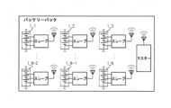
電気自動車のように大容量であり、かつ高電圧が求められる装置のためのバッテリーパックは、通常的に互いに直列で接続された複数のバッテリーモジュールを含む。複数のバッテリーモジュールの状態を効率的に管理するために、マルチスレーブ体系を有する無線制御システムが開示されている。マルチスレーブ体系を有する無線制御システムは、図1に示したように、各バッテリーモジュール1_1~1_Nの状態をモニターするための複数のスレーブモジュールと、各スレーブモジュールの情報に基づいて全体のバッテリーパックの状態を統合的に管制するマスターモジュールと、を含む。A battery pack for a device requiring large capacity and high voltage, such as an electric vehicle, typically includes multiple battery modules connected in series with each other. In order to efficiently manage the status of the multiple battery modules, a wireless control system with a multi-slave system has been disclosed. As shown in FIG. 1, the wireless control system with a multi-slave system includes multiple slave modules for monitoring the status of each battery module 1_1 to 1_N, and a master module for integrating and controlling the status of the entire battery pack based on information from each slave module.
ところが、マスターモジュールと複数のスレーブモジュールが相互間の無線通信を行う場合、外部ノイズの影響によってマスターモジュールと少なくとも一つのスレーブモジュールとの無線接続が意図せず切れてしまうことがあり、その解決方案が模索されている。However, when a master module and multiple slave modules communicate wirelessly with each other, the wireless connection between the master module and at least one slave module may be unintentionally cut off due to external noise, and solutions to this problem are being sought.
本発明は、上記問題点に鑑みてなされたものであり、バッテリーパック内の構造物を導波管として活用してマスターモジュールと複数のスレーブモジュールとの間の無線信号の伝達経路を統制し、外部ノイズが遮断可能なバッテリーパック及び当該バッテリーパックを含む自動車を提供することを目的とする。The present invention was made in consideration of the above problems, and aims to provide a battery pack and an automobile including the battery pack that can block external noise by controlling the transmission path of wireless signals between a master module and multiple slave modules by utilizing structures within the battery pack as a waveguide.
本発明の他の目的及び長所は、下記の説明によって理解でき、本発明の実施例によってより明らかに理解されるであろう。また、本発明の目的及び長所は、特許請求の範囲に示される手段及びその組合せによって実現することができる。Other objects and advantages of the present invention can be understood from the following description and will become more clearly understood from the examples of the present invention. The objects and advantages of the present invention can be realized by the means and combinations thereof shown in the claims.
上記の課題を達成するための本発明の多様な実施例は、以下のようである。Various embodiments of the present invention to achieve the above objectives are as follows:
本発明の一面によるバッテリーパックは、パックケースと、前記パックケースに搭載される複数個のバッテリーモジュールと、各々の前記バッテリーモジュールに一つずつ取り付けられて前記バッテリーモジュールの状態をモニターするように構成され、無線通信のためのスレーブアンテナを備える複数個のスレーブモジュールと、前記複数個のスレーブモジュールからの情報に基づいて、前記バッテリーモジュールの状態を統合管理するように構成され、無線通信のためのマスターアンテナを備えるマスターモジュールと、前記パックケースの内部に設けられ、前記複数個のスレーブモジュールと前記マスターモジュールとの間の無線通信経路を形成する導波管と、を含み得る。A battery pack according to one aspect of the present invention may include a pack case, a plurality of battery modules mounted in the pack case, a plurality of slave modules attached to each of the battery modules and configured to monitor the state of the battery module and equipped with a slave antenna for wireless communication, a master module configured to integrally manage the state of the battery modules based on information from the plurality of slave modules and equipped with a master antenna for wireless communication, and a waveguide provided inside the pack case and forming a wireless communication path between the plurality of slave modules and the master module.
前記導波管は、中空の管状で設けられた本体部と、一側が前記本体部と連通し、他側が前記スレーブモジュールと対面して接触するように設けられたスレーブドッキング部と、一側が前記本体部と連通し、他側が前記マスターモジュールと対面して接触するように設けられたマスタードッキング部と、を含み得る。The waveguide may include a hollow tubular main body, a slave docking section having one side communicating with the main body and the other side facing and in contact with the slave module, and a master docking section having one side communicating with the main body and the other side facing and in contact with the master module.
前記本体部は、前記パックケースの内部空間を横切るように延び、一端部と他端部が前記パックケースの一側の内壁と他側の内壁に固定結合して前記パックケースを支持するように設けられ得る。
複数個の前記スレーブドッキング部が備えられ、前記複数個のスレーブドッキング部は、一対ずつ前記本体部を基準にして互いに反対方向に位置し、前記本体部の延長方向に沿って所定の間隔毎に設けられ得る。 The main body may extend across an internal space of the pack case, and one end and the other end may be fixedly coupled to one inner wall and the other inner wall of the pack case to support the pack case.
A plurality of the slave docking parts may be provided, and the slave docking parts may be arranged in pairs in opposite directions with respect to the main body and at predetermined intervals along an extension direction of the main body.
前記スレーブドッキング部または前記マスタードッキング部は、前記スレーブモジュールにおいて前記スレーブアンテナの位置または前記マスターモジュールにおいて前記マスターアンテナの位置をカバーするように設けられた外側開放口と、前記外側開放口の周縁に沿って拡張して形成されたフランジと、外部電磁波遮蔽機能を備え、前記フランジに介在されるシールドガスケットと、を含み得る。The slave docking section or the master docking section may include an outer opening provided to cover the position of the slave antenna in the slave module or the position of the master antenna in the master module, a flange formed by extending along the periphery of the outer opening, and a shielding gasket interposed in the flange and having an external electromagnetic wave shielding function.
前記シールドガスケットは、ワイヤメッシュガスケットまたはソフトフォームに電磁波吸収素材をコーティングした電磁波吸収スポンジのいずれか一つとして設けられ得る。The shielding gasket can be provided as either a wire mesh gasket or an electromagnetic wave absorbing sponge made of soft foam coated with an electromagnetic wave absorbing material.
前記スレーブモジュール及び前記マスターモジュールは、外観を形成するモジュールカバーを含み、前記モジュールカバーは、前記スレーブアンテナまたは前記マスターアンテナが位置する部分を除いて電波遮断素材からなるか、または電波遮断物質がコーティングされ得る。The slave module and the master module each include a module cover that forms the exterior, and the module cover may be made of a radio wave blocking material or coated with a radio wave blocking material, except for the portion where the slave antenna or the master antenna is located.
前記本体部の内部に備えられ、前記本体部と連通する部分になる前記スレーブドッキング部の内側開放口を開閉するように設けられた反射板をさらに含み得る。The device may further include a reflector provided inside the main body and configured to open and close the inner opening of the slave docking unit, which is the part that communicates with the main body.
前記反射板は、前記本体部の内側面に回転軸が備えられ、前記回転軸を中心にして回転して回転角度を調節できるように設けられ得る。The reflector may be provided with a rotation axis on the inner surface of the main body, and may be configured to rotate around the rotation axis to adjust the rotation angle.
前記パックケースは、前記複数個のバッテリーモジュールが載置されるパックトレイと、前記パックトレイと相互に結合し、前記複数個のバッテリーモジュールの上部をカバーするパックカバーと、を含み得る。The pack case may include a pack tray on which the plurality of battery modules are placed, and a pack cover that is connected to the pack tray and covers the upper portion of the plurality of battery modules.
前記パックカバーの内面に備えられる電波吸収体をさらに含み得る。It may further include a radio wave absorber provided on the inner surface of the pack cover.
前記導波管は、前記パックトレイの中心ラインに沿って前記パックトレイの底面に設けられ、前記複数個のバッテリーモジュールは、前記導波管を基準で互いに対向して配置され得る。The waveguide is provided on the bottom surface of the pack tray along the center line of the pack tray, and the battery modules may be arranged facing each other with respect to the waveguide.
前記導波管は、前記本体部の下部に前記本体部よりも大きい幅に形成され、前記パックトレイの底面に固定結合するベースフレーム部をさらに含み、前記バッテリーモジュールは、前記ベースフレーム部の上端面にボルト締結によって固定され得る。The waveguide further includes a base frame portion formed at the bottom of the body portion with a width greater than that of the body portion and fixedly coupled to the bottom surface of the pack tray, and the battery module can be fixed to the upper end surface of the base frame portion by bolt fastening.
本発明の他の様態によると、前述したバッテリーパックを含む自動車が提供され得る。According to another aspect of the present invention, a vehicle may be provided that includes the battery pack described above.
本発明によるバッテリーパックは、以下のような効果を奏する。The battery pack of the present invention provides the following advantages:
バッテリーパック内に備えられる導波管によって無線信号の伝達経路が統制されることでマスターモジュールと複数個のスレーブモジュールの相互間の通信の高信頼性が確保できる。The transmission path of wireless signals is controlled by a waveguide installed inside the battery pack, ensuring high reliability of communication between the master module and multiple slave modules.
また、導波管がパックケースの強度補強構造物ないしバッテリーモジュールをマウントする構造物として活用可能である。本発明による導波管は、従来技術のバッテリーパックのクロスビームのような機能を兼ねることで、導波管の追加によるバッテリーパックの容積率が低下しない。The waveguide can also be used as a strength reinforcing structure for the pack case or as a structure for mounting the battery module. The waveguide of the present invention also functions as a cross beam in the battery pack of the prior art, so the volume ratio of the battery pack is not reduced by adding the waveguide.
本発明の効果は上述した効果に制限されず、言及されていない本発明の他の効果は請求範囲の記載から当業者により明らかに理解されるだろう。The effects of the present invention are not limited to those described above, and other effects of the present invention not mentioned will be clearly understood by those skilled in the art from the description of the claims.
本明細書に添付される次の図面は、本発明の望ましい実施例を例示するものであり、発明の詳細な説明とともに本発明の技術的な思想をさらに理解させる役割をするため、本発明は図面に記載された事項だけに限定されて解釈されてはならない。The following drawings attached to this specification are illustrative of preferred embodiments of the present invention and, together with the detailed description of the invention, serve to further understand the technical concept of the present invention, and therefore the present invention should not be interpreted as being limited to only the matters depicted in the drawings.
以下、添付された図面を参照して本発明の望ましい実施例を詳しく説明する。これに先立ち、本明細書及び特許請求の範囲に使われた用語や単語は通常的や辞書的な意味に限定して解釈されてはならず、発明者自らは発明を最善の方法で説明するために用語の概念を適切に定義できるという原則に則して本発明の技術的な思想に応ずる意味及び概念で解釈されねばならない。したがって、本明細書に記載された実施例及び図面に示された構成は、本発明のもっとも望ましい一実施例に過ぎず、本発明の技術的な思想のすべてを代弁するものではないため、本出願の時点においてこれらに代替できる多様な均等物及び変形例があり得ることを理解せねばならない。Hereinafter, a preferred embodiment of the present invention will be described in detail with reference to the attached drawings. Prior to this, the terms and words used in this specification and claims should not be interpreted as being limited to their ordinary or dictionary meanings, but should be interpreted with meanings and concepts corresponding to the technical ideas of the present invention, in accordance with the principle that the inventor himself can appropriately define the concepts of terms in order to best describe the invention. Therefore, it should be understood that the embodiment described in this specification and the configuration shown in the drawings are only one most preferred embodiment of the present invention, and do not represent the entire technical ideas of the present invention, and therefore there may be various equivalents and modifications that can be substituted for them at the time of this application.
本発明の実施形態は、通常の技術者に本発明をより完全に説明するために提供されるものであり、図面における構成要素の形状及び大きさなどは、より明確な説明のために誇張または省略されるか、概略的に示されることがある。したがって、各構成要素の大きさや割合は、実際の大きさや割合を完全に反映することではない。The embodiments of the present invention are provided to more completely explain the present invention to those of ordinary skill in the art, and the shapes and sizes of components in the drawings may be exaggerated, omitted, or shown diagrammatically for a clearer explanation. Therefore, the size and proportion of each component do not completely reflect the actual size and proportion.
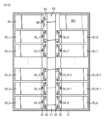
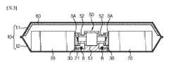
図2は、本発明の一実施例によるバッテリーパックの内部構成を概略的に示した図であり、図3は、本発明の一実施例によるバッテリーパックの断面を概略的に示した図である。Figure 2 is a diagram showing a schematic internal configuration of a battery pack according to one embodiment of the present invention, and Figure 3 is a diagram showing a schematic cross section of a battery pack according to one embodiment of the present invention.
図2及び図3を参照すると、本発明の一実施例によるバッテリーパックは、パックケース10と、複数個のバッテリーモジュール20と、複数個のスレーブモジュール30と、マスターモジュール40と、導波管50と、を含む。Referring to Figures 2 and 3, a battery pack according to one embodiment of the present invention includes a
パックケース10は、バッテリーモジュール20が載置される空間を提供するパックトレイ12と、パックトレイ12の上部をカバーし、パックトレイ12の上端に結合するパックカバー11と、を含む。The
パックトレイ12は、バッテリーモジュール20、マスターモジュール40、バッテリー遮断ユニット(BDU,Battery Disconnection Unit)などを載置できるように広い板状体の形態に形成された下部プレートと、下部プレートのエッジに沿って壁体を形成する側面プレートと、からなり、上部がオープンされた形態で設けられ得る。The
ここで、前記マスターモジュール40は、バッテリーモジュール20をリアルタイムでモニターして各バッテリーモジュール20の状態を、診断、推定、管理する構成品である。マスターモジュール40は、当業界でマスターBMS(Battery Management System)に指称され得る。そして、バッテリー遮断ユニットは、電力制御部品の一つとして、リレー、電流センサー、抵抗などから構成され、バッテリーと負荷との間で電力を接続または遮断する部品を総称する。Here, the
パックカバー11は、側面プレートの上端ラインに沿って、接着、フックまたはボルト締結などの方式でパックトレイ12の上端に結合し、バッテリーモジュール20の上部をカバー可能に設けられ得る。前記パックカバー11は、内部構成品を外部から保護するようにスチールなどのように剛性の金属材質から製作することが望ましい。パックトレイ12とパックカバー11との接触部位には、気密性のためにガスケット(図示せず)がさらに加えられ得る。The pack cover 11 can be attached to the upper end of the
特に、本実施例のパックカバー11は、図2のように、その内面に電波吸収体60(wave absorber)を含む。ここで、電波吸収体60とは、入射電波を吸収して熱に変換して反射波を発生させない物質をいう。例えば、電波吸収体60は、樹脂に磁性粉末を混合したシート(Sheet)状に製作され、パックカバー11の内面に付着され得る。In particular, the pack cover 11 of this embodiment includes a wave absorber 60 on its inner surface, as shown in FIG. 2. Here, the wave absorber 60 refers to a material that absorbs incident radio waves, converts them into heat, and does not generate reflected waves. For example, the
このように電波吸収体60をパックカバー11の内面に付着すると、無線信号を伝達する電波がパックカバー11によって反射されないため、マルチパスフェージング(multipath fading)による影響及び外部へ反射されて他の装置に及ぶ影響を最小化できる。When the radio wave absorber 60 is attached to the inner surface of the pack cover 11 in this way, the radio waves transmitting the wireless signal are not reflected by the pack cover 11, minimizing the effects of multipath fading and the effects of the radio waves being reflected to the outside and affecting other devices.
前記シートの代案として電波吸収塗料が用いられ得る。即ち、パックカバー11の内側面に電波吸収塗料を厚く塗って前記シートを付着したことと同じ効果を発揮できる。As an alternative to the sheet, radio wave absorbing paint can be used. That is, the same effect can be achieved by applying a thick layer of radio wave absorbing paint to the inside surface of the pack cover 11 and attaching the sheet.
複数個のバッテリーモジュール20は、互いに直列または直列と並列で接続され、各バッテリーモジュール20は少なくとも一つのバッテリーセル(図示せず)を含む。複数個のバッテリーモジュール20を区分するための目的で、図2において、複数個のバッテリーモジュール20に符号20_1~20_N(Nは、2以上の自然数である。)を付与した。The
前記バッテリーセルとしては、パウチ型二次電池、角形二次電池または円筒型二次電池のいずれかを採用してもよい。The battery cell may be a pouch-type secondary battery, a rectangular secondary battery, or a cylindrical secondary battery.
スレーブモジュール30は、バッテリーモジュール20当たり一つずつバッテリーモジュール20の前面部に取り付けられ、当該バッテリーモジュール20の状態をモニター及び管理する役割を果たす構成要素である。スレーブモジュール30は、当業界でスレーブBMS(Battery Module System)に指称され得る。通常的に、前記スレーブモジュール30は、バッテリーモジュール20と機械的、電気的に接続され、バッテリーモジュール20の一側に統合した形態で提供される。したがって、スレーブモジュール30の個数は、複数個のバッテリーモジュール20の個数と同一である。The
各スレーブモジュール30は、センシング部(図示せず)、無線通信回路(図示せず)、スレーブアンテナSA及びスレーブ制御部(図示せず)を含み得る。Each
センシング部は、電圧測定回路、温度センサー、電流センサーを含み得る。The sensing unit may include a voltage measurement circuit, a temperature sensor, and a current sensor.
電圧測定回路は、バッテリーモジュール20のモジュール電圧を測定する。モジュール電圧は、バッテリーモジュール20の両端にかかる電圧である。また、電圧測定回路は、バッテリーモジュール20に含まれた各バッテリーセルのセル電圧をさらに測定し得る。セル電圧は、バッテリーセルの両端にかかる電圧である。電圧測定回路は、モジュール電圧とセル電圧を示す電圧信号を制御部へ伝送する。The voltage measurement circuit measures the module voltage of the
温度センサーは、バッテリーモジュール20から所定の距離内に配置され、バッテリーモジュール20の温度を示す温度信号をスレーブ制御部に伝送する。The temperature sensor is positioned within a predetermined distance from the
電流センサーは、バッテリーパックの充放電電流経路に設けられ、バッテリーパックの充放電時に流れる電流を測定し、測定された電流を示す電流信号をスレーブ制御部に伝送する。The current sensor is installed in the charge/discharge current path of the battery pack, measures the current that flows when the battery pack is charged or discharged, and transmits a current signal indicating the measured current to the slave control unit.
無線通信回路は、ハードウェア的に、RF SoC(System on Chip)を用いて具現され、スレーブ制御部及びスレーブアンテナSAに接続される。各スレーブモジュール30に備えられるスレーブアンテナSAを区分するための目的で、図2においてスレーブアンテナSAが位置した所に符号SA_1~SA_N(Nは、2以上の自然数である。)を付与した。無線通信回路は、スレーブアンテナSAを介してマスターモジュール40へデータを無線伝送するか、またはマスターモジュール40からデータを無線受信し得る。また、無線通信回路は、スレーブアンテナSAを介してある信号が受信された場合、受信された信号の信号強度(signal strength)を測定し得る。The wireless communication circuit is implemented in hardware using an RF SoC (System on Chip) and is connected to the slave controller and the slave antenna SA. In order to distinguish the slave antennas SA provided in each
スレーブ制御部は、センシング部及び無線通信回路に動作可能に結合し、これらの各々の動作を個別的に制御するように構成され得る。The slave control unit may be operatively coupled to the sensing unit and the wireless communication circuitry and configured to individually control the operation of each of them.
マスターモジュール40は、バッテリーパックを統合制御する構成要素であって、CAN(Control Area Network)のような有線ネットワークを通じて外部のメインコントローラー(例えば、電気自動車のECU)と通信するように構成される。The
また、マスターモジュール40は、無線通信回路(図示せず)、マスター制御部(図示せず)及びマスターアンテナMAを含み、マスターアンテナMAを介して各スレーブモジュール30と無線通信可能に構成される。The
前記無線通信回路は、マスターアンテナMAを介してスレーブモジュール30へ命令パケットを無線伝送するように構成される。また、無線通信回路は、マスターアンテナMAを介してスレーブモジュール30からの応答パケットを受信するように構成される。The wireless communication circuit is configured to wirelessly transmit command packets to the
複数のスレーブモジュール30は各々、予め割り当てられた自分のIDを用いて、マスターモジュール40と無線通信を行い、マスターモジュール40は、複数のスレーブに予め割り当てられているIDを保存する。前記IDは、複数のスレーブを区別するための識別情報である。Each of the
マスターモジュール40は、スレーブモジュール30からのバッテリー情報に基づいて、各バッテリーモジュール20のSOC(state of charge)、SOH(state of health)などを演算するか、または各バッテリーモジュール20の過電圧、不足電圧、過充電または過放電の有無を判定し得る。Based on the battery information from the
マスター制御部は、無線通信回路に動作可能に接続される。マスター制御部は、マスターアンテナMAを介して受信される信号に基づいて、複数のスレーブの少なくとも一つに対する要請事項を決定し、前記要請事項を示すデータを含む命令パケットを複数のスレーブモジュール30の少なくとも一つに無線で伝送し得る。The master control unit is operatively connected to the wireless communication circuit. The master control unit can determine a request for at least one of the multiple slaves based on a signal received via the master antenna MA, and wirelessly transmit a command packet including data indicating the request to at least one of the
一方、本発明の実施例によるバッテリーパックは、前記複数個のスレーブモジュール30と前記マスターモジュール40との無線通信経路が統制されるように無線通信経路を形成する導波管50を含む。Meanwhile, the battery pack according to an embodiment of the present invention includes a
以下では、図2及び図3を共に、図4~図9を参照して前記導波管50の構成と作用について詳しく説明する。The configuration and operation of the
導波管50は、アンテナと受信機との間で電波のエネルギー損失と外部ノイズの干渉を最小化しながら電波を伝達する役割を果たすものであって、中空の金属管状であり、断面が長方形または円形に製作可能であり、導波管50の大きさは無線通信周波数に応じて多様に決定され得る。The
このような導波管50は、電磁波が導波管50の制限された内部空間に沿って移動するようにし、その内面に電流が流れないため、電磁波のエネルギー損失を減らすことができる。また、導波管50の内部は空気で満たされており、誘電体損失も少ない。Such a
本発明は、前記導波管50を各スレーブモジュール30とマスターモジュール40との間の無線伝達経路として使用する。このために、外部からの衝撃時、パックケース10の歪み防止用として通常適用しているパックケース10内のクロスビームを導波管50から構成した。したがって、本実施例の導波管50は、無線信号伝送経路とパックケース10の強度補強構造物との二つの役割を果たす。The present invention uses the
図2に示したように、本実施例の導波管50は、パックケース10の中央領域を横切るように延びてパックケース10の内部空間を両分するようにパックトレイ12の底面に設けられ得る。また、導波管50の一端部と他端部は各々パックトレイ12の一側内壁と他側内壁に固定結合され得る。このような導波管50によってパックケース10の両壁体が支持されることで、外部衝撃によるパックケース10の歪み及び変形を防止できる。As shown in FIG. 2, the
前記導波管50は、図4及び図5に示したように、本体部51と、スレーブドッキング部52と、マスタードッキング部53と、ベースフレーム部54と、を含む。As shown in Figures 4 and 5, the
本体部51は、中空の長方形の金属管状で設けられる。前記本体部51は、上部が開閉可能に設けられ得る。例えば、本体部51は、上部が開放された胴体と、このような胴体を覆う上板51aで構成され得る。このような構成の本体部51は、その内部にほこりや異物が流れ込む場合、上板51aを分離して内部の掃除を容易に行うことができるという利点がある。The
スレーブドッキング部52は、各バッテリーモジュール20のスレーブモジュール30と連結される部分であって、その一側は本体部51の内部と連通し、他側はスレーブモジュール30と対面して接触するように設けられる。The
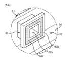
スレーブドッキング部52は、本体部51の外側面から突出するように設けられた外側開放口52a、前記外側開放口52aの周りに沿って拡張して形成されたフランジ52b、前記フランジ52bに介在される電磁波シールドガスケット52c、そして内側開放口52eを含む。The
外側開放口52aは、無線電波信号が導波管50内へ最も効率的に伝達されるように、スレーブモジュール30においてスレーブアンテナSAが位置した領域の面積に対応するサイズで設けられて前記スレーブアンテナSA領域をカバーする。The
フランジ52bは、スレーブモジュール30の外観を形成するモジュールカバーと対面接触する部分である。このようなフランジ52bを用いてモジュールカバーとの接触面積を広げることで、前記モジュールカバーの打痕やスクラッチを防止し、スレーブモジュール30に加えられる衝撃を緩和させることができる。The
前記モジュールカバーは、外部の無線干渉を最小化するために、フランジ52bと接点をなす部分の外側領域が、電磁波シールド機能を備える金属、または電磁波シールド機能を備えるシートまたは塗料が表面に備えられた非金属材質から形成され得る。即ち、前記モジュールカバーは、内側に前記スレーブアンテナSAが位置した部分を除いて電波遮断素材からなるなるか、または電波遮断物質がコーティングされたものであり得る。In order to minimize external radio interference, the outer area of the module cover that comes into contact with the
図6を参照すると、電磁波シールドガスケット52cは、導波管50に流入し得る外部の電磁波干渉を無くすためのものであって、ポリウレタンフォームのようにソフトフォームに電磁波吸収素材を特殊コーティングした電磁波吸収スポンジが適用され得る。前記電磁波吸収スポンジは、フランジ52bの表面に接着などの方式で付着され得る。このような電磁波吸収スポンジは、その特性上、柔軟性と弾力性が優秀であるため、モジュールカバーとの接触時、スクラッチ防止効果も奏する。Referring to FIG. 6, the electromagnetic
電磁波吸収スポンジの代案としては、図7に示したようなワイヤメッシュシールドガスケット52dが採用され得る。ワイヤメッシュシールドガスケット52dは、メタルワイヤをニッティング方式で製織して柔軟性に優れ、相対物との接触が優秀で電磁波遮蔽効果が高い。前記ワイヤメッシュの内部にシリコーンエラストマ、ウレタンスポンジなどを芯材として入れることも可能である。As an alternative to the electromagnetic wave absorbing sponge, a wire
前記ワイヤメッシュシールドガスケット52dは、フランジ52bの表面に接着テープで付着するか、または変形例のように、フランジ52bに溝を形成し、前記溝に挿入して固定する方式でフランジ52bに設け得る。The wire
マスタードッキング部53は、前述したスレーブドッキング部52と構造は実質的に同一であるが、連結対象がマスターモジュール40であることが相違する。即ち、マスタードッキング部53(図2参照)は、一側が本体部51と連通し、他側がマスターモジュール40と対面接触するように設けられる。そして、マスタードッキング部53の外側開放口52aは、マスターモジュール40においてマスターアンテナMAの位置をカバー可能な大きさで設けられ得る。The
ベースフレーム部54は、パックトレイ12の底面に固定結合する部分であって、本体部51の下部に位置し、本体部51より大きい幅に形成される。前記ベースフレーム部54は、パックトレイ12の底面と溶接またはボルト締結方式で結合し得る。The
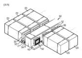
前記ベースフレーム部54は、本体部51より大きい幅に形成されていることで、バッテリーモジュール20をマウントする場所として活用可能である。図3~図5に示したように、ベースフレーム部54の上端面に配置されたマウンティングブラケット21とベースフレーム部54とをボルトBで結合して各バッテリーモジュール20を導波管50に固定し得る。この場合、各バッテリーモジュール20のスレーブモジュール30は、対応する導波管50のスレーブドッキング部52に正確にアラインでき、アラインの後、外部衝撃があっても方向がずれることがない。The
続いて、図8及び図9を参照して、前記導波管50に各スレーブモジュール30及びマスターモジュール40を連結する過程を説明すると、以下のようである。Next, the process of connecting each
先ず、パックトレイ12の中心ラインに沿って導波管50が置かれるようにパックトレイ12の底面に設ける。そして、図8に示したように、一対ずつのバッテリーモジュール20を前記導波管50を基準で対称的に互いに向い合うように配置する。前述したように、各スレーブモジュール30は、各バッテリーモジュール20に装着されており、前記一対ずつのバッテリーモジュール20が互いに向い合う方向は、各スレーブモジュール30が導波管50に向かう方向である。First, the
その後、図9に示したように、各スレーブモジュール30においてスレーブアンテナSA領域とスレーブドッキング部52の外側開放口52aとをマッチングする。この際、バッテリーモジュール20のマウンティングブラケット21のホールH1と導波管50のベースフレーム部54の上端面のホールH2とが上下に一致すると、導波管50とスレーブモジュール30とが正確にアラインされたといえる。この状態で前記ブラケットをベースフレーム部54にボルト締結してバッテリーモジュール20を導波管50に固定する。Then, as shown in FIG. 9, the slave antenna SA area is matched with the
上記のようなパターンで導波管50の延長方向に沿って各バッテリーモジュール20を導波管50に固定して各スレーブアンテナSAが導波管50の各スレーブドッキング部52の内部に向かうようにする。マスターモジュール40の場合にも、スレーブモジュール30と同様にマスターアンテナMAが導波管50のマスタードッキング部53の内部に向かうようにする。In the above pattern, each
以上のように本発明の一実施例による構成によると、各スレーブモジュール30とマスターモジュール40との間の無線信号の電波伝達経路が前記導波管50内に制限され、外部電波の干渉が最小化することで、各スレーブモジュール30とマスターモジュール40との無線通信の信頼性を高めることができる。As described above, according to the configuration of one embodiment of the present invention, the radio wave transmission path of the wireless signal between each
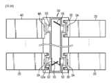
図10は、本発明の他の実施例による導波管50の内部構成を概略的に示した図である。Figure 10 is a schematic diagram showing the internal configuration of a
続いて、図10を参照して本発明の他の実施例を説明する。前述した実施例と同じ部材符号は同じ部材を示し、同じ部材に対して重複する説明は省略し、前述した実施例との差異点を中心にして説明する。Next, another embodiment of the present invention will be described with reference to FIG. 10. The same reference numerals as in the previously described embodiment indicate the same components, and redundant descriptions of the same components will be omitted. The following description will focus on the differences from the previously described embodiment.
本発明の他の実施例によるバッテリーパックは、前述した実施例のバッテリーパックと比較すると、導波管50の内部に反射板55をさらに含む。Compared to the battery pack of the above-mentioned embodiment, the battery pack according to another embodiment of the present invention further includes a
前記反射板55は、各スレーブドッキング部52の内側開放口52eを開閉可能に本体部51の内部に設けられる。例えば、反射板55は、内側開放口52eを十分覆い得るサイズに形成され、本体部51の内側面のうち前記内側開放口52eの周辺に回転軸を備え、0°~180°の範囲で回転するように設けられ得る。前記反射板55の回転角度は、反射板55の回転軸にサーボモーター(図示せず)を接続して精密に調節可能である。サーボモーターは、各スレーブモジュール30の制御部またはマスターモジュール40の制御部と有線または無線で接続され、前記制御部の命令に応じて作動され得る。The
このような本発明の他の実施例の構成によると、無線信号の伝達経路が前述した実施例よりも効果的に統制できる。例えば、図10のように、マスターモジュール40と通信していないスレーブモジュール30の通信経路は、反射板55によって遮蔽されるようにして電波干渉を最小化できる。また、マスターモジュール40と通信している各スレーブモジュール30の通信経路は、反射板55によってさらに効果的に統制できる。例えば、マスターモジュール40または各スレーブモジュール30は、RSSI(Received Signal Strength Indication、受信信号強度)によって信号強度を感知し、各スレーブアンテナSA毎にマスターアンテナMAと交換する信号が最も円滑なときの反射板55の最適開放角度を探す。反射板55は、各スレーブモジュール30毎に前記最適開放角度に合わせて調節され、信号強度が適正水準以上に維持されるようにする。According to the configuration of this other embodiment of the present invention, the transmission path of the wireless signal can be controlled more effectively than the above-mentioned embodiment. For example, as shown in FIG. 10, the communication path of the
図11は、本発明の自動車を概略的に示した図である。Figure 11 is a schematic diagram of a vehicle according to the present invention.
本発明によるバッテリーパック100は、電気自動車やハイブリッド自動車のような自動車Vの動力エネルギー源として含まれ得る。即ち、本発明による自動車Vは、前述したバッテリーパック100を含み得る。The
前記バッテリーパック100は、電気自動車Vに搭載され、電気自動車Vの電気モーターの駆動に求められる電力を提供し得る。また、前記バッテリーパック100のマスターモジュールは、CAN(Control Area Network)のような有線ネットワークを通じて外部の電気自動車のECU(Electronic Control Unit)と通信し得る。The
前記自動車Vの外にも二次電池を用いる電力貯蔵装置(Energy Storage System)などのその他の装置や器具及び設備などにも備えられ得ることは勿論である。Of course, the present invention can also be installed in other devices, equipment, and facilities such as an energy storage system that uses a secondary battery, in addition to the vehicle V.
以上、本発明の望ましい実施例について図示及び説明したが、本発明は上述した特定の望ましい実施例に限定されず、特許請求の範囲で請求する本発明の要旨から外れることなく当該発明が属する技術分野における通常の知識を持つ者によって多様に変形できることは言うまでもなく、かかる変形は、特許請求範囲記載の範囲内に含まれる。Although the preferred embodiment of the present invention has been illustrated and described above, the present invention is not limited to the specific preferred embodiment described above, and it goes without saying that various modifications can be made by a person having ordinary skill in the art to which the invention pertains without departing from the gist of the present invention as claimed in the claims, and such modifications are included within the scope of the claims.
なお、本明細書において、上、下、左、右のような方向を示す用語が使用されたが、このような用語は相対的な位置を示し、説明の便宜のためのものであるだけで、対象となる事物の位置や観測者の位置などによって変わり得ることは、当業者にとって自明である。In this specification, terms indicating directions such as up, down, left, and right are used, but it will be obvious to those skilled in the art that these terms indicate relative positions and are used merely for convenience of explanation, and may vary depending on the position of the object in question or the position of the observer, etc.
10 パックケース
11 パックカバー
12 パックトレイ
20 バッテリーモジュール
21 マウンティングブラケット
30 スレーブモジュール
40 マスターモジュール
50 導波管
51 本体部
51a 上板
52 スレーブドッキング部
52a 外側開放口
52b フランジ
52c 電磁波シールドガスケット
52d ワイヤメッシュシールドガスケット
52e 内側開放口
53 マスタードッキング部
54 ベースフレーム部
55 反射板
60 電波吸収体
100 バッテリーパック10 pack case 11
Claims (13)
Translated fromJapanese前記パックケースに搭載される複数個のバッテリーモジュールと、
各々の前記バッテリーモジュールに一つずつ取り付けられて前記バッテリーモジュールの状態をモニターするように構成され、無線通信のためのスレーブアンテナを備える複数個のスレーブモジュールと、
前記複数個のスレーブモジュールからの情報に基づいて、前記バッテリーモジュールの状態を統合管理するように構成され、無線通信のためのマスターアンテナを備えるマスターモジュールと、
前記パックケースの内部に設けられ、前記複数個のスレーブモジュールと前記マスターモジュールとの間の無線通信経路を形成する導波管と、を含み、
前記導波管は、
中空の管状で設けられた本体部と、
複数個のスレーブドッキング部の各々が、一側が前記本体部と連通し、他側が前記スレーブモジュールと対面して接触するように設けられた、複数個のスレーブドッキング部と、
一側が前記本体部と連通し、他側が前記マスターモジュールと対面して接触するように設けられたマスタードッキング部と、を含むことを特徴とする、バッテリーパック。 Pack case and
a plurality of battery modules mounted in the pack case;
a plurality of slave modules each attached to each of the battery modules to monitor a state of the battery module, the slave modules including a slave antenna for wireless communication;
a master module configured to integrally manage the states of the battery modules based on information from the plurality of slave modules, the master module including a master antenna for wireless communication;
a waveguide provided inside the pack case and forming a wireless communication path between the plurality of slave modules and the master module;
The waveguide is
A main body portion having a hollow tubular shape;
a plurality of slave docking units, each of which has one side communicating with the main body and the other side facing and in contact with the slave module;
a master docking portion having one side communicating with the main body portion and the other side provided to face and contact the master module.
前記スレーブモジュールにおいて前記スレーブアンテナの位置または前記マスターモジュールにおいて前記マスターアンテナの位置をカバーするように設けられた外側開放口と、
前記外側開放口の周縁に沿って拡張して形成されたフランジと、
外部電磁波遮蔽機能を備え、前記フランジに介在されるシールドガスケットと、を含むことを特徴とする、請求項1から3のいずれか一項に記載のバッテリーパック。 The slave docking unit or the master docking unit is
an outer opening provided to cover the position of the slave antenna in the slave module or the position of the master antenna in the master module;
a flange formed by expanding along a periphery of the outer opening;
The battery pack according to claim1 ,further comprising: a shielding gasket having an external electromagnetic wave shielding function and interposed between the flanges.
前記モジュールカバーは、前記スレーブアンテナまたは前記マスターアンテナが位置する部分を除いて電波遮断素材からなるか、または電波遮断物質がコーティングされたことを特徴とする、請求項4または5に記載のバッテリーパック。 The slave module and the master module each include a module cover that forms an external appearance;
6. The battery pack according to claim4 , wherein the module cover is made of a radio wave blocking material or is coated with a radio wave blocking material except for a portion where the slave antenna or the master antenna is located.
前記複数個のバッテリーモジュールが載置されるパックトレイと、前記パックトレイと相互に結合し、前記複数個のバッテリーモジュールの上部をカバーするパックカバーと、を含むことを特徴とする、請求項1から8のいずれか一項に記載のバッテリーパック。 The pack case includes:
9. The battery pack of claim1 , comprising: a pack tray on which the plurality of battery modules are placed; and a pack cover coupled to the pack tray and covering an upper portion of the plurality of battery modules.
前記複数個のバッテリーモジュールは、前記導波管を基準で互いに対向して配置されることを特徴とする、請求項9または10に記載のバッテリーパック。 the waveguide is provided on a bottom surface of the pack tray along a center line of the pack tray,
The battery pack according to claim9 or10 , wherein the plurality of battery modules are disposed facing each other with respect to the waveguide.
前記本体部の下部に前記本体部よりも大きい幅に形成され、前記パックトレイの底面に固定結合するベースフレーム部をさらに含み、
前記バッテリーモジュールは、前記ベースフレーム部の上端面にボルト締結によって固定されることを特徴とする、請求項9から11のいずれか一項に記載のバッテリーパック。 The waveguide is
a base frame part formed at a lower part of the body part with a width larger than that of the body part and fixedly coupled to a bottom surface of the pack tray,
The battery pack according to claim9, wherein the battery module is fixed to an upper end surface of the base frame by bolt fastening.
Applications Claiming Priority (3)
| Application Number | Priority Date | Filing Date | Title |
|---|---|---|---|
| KR10-2020-0066573 | 2020-06-02 | ||
| KR1020200066573AKR20210149482A (en) | 2020-06-02 | 2020-06-02 | A battery rack with optimization structure for wireless communication and energy storage device including the same |
| PCT/KR2021/004169WO2021246633A1 (en) | 2020-06-02 | 2021-04-02 | Battery pack having optimization structure for wireless communication, and vehicle comprising same |
Publications (2)
| Publication Number | Publication Date |
|---|---|
| JP2023504158A JP2023504158A (en) | 2023-02-01 |
| JP7550855B2true JP7550855B2 (en) | 2024-09-13 |
Family
ID=78831324
Family Applications (1)
| Application Number | Title | Priority Date | Filing Date |
|---|---|---|---|
| JP2022532650AActiveJP7550855B2 (en) | 2020-06-02 | 2021-04-02 | Battery pack with optimized structure for wireless communication and automobile including same |
Country Status (6)
| Country | Link |
|---|---|
| US (1) | US20230071238A1 (en) |
| EP (1) | EP4057417A4 (en) |
| JP (1) | JP7550855B2 (en) |
| KR (1) | KR20210149482A (en) |
| CN (1) | CN114846672A (en) |
| WO (1) | WO2021246633A1 (en) |
Families Citing this family (17)
| Publication number | Priority date | Publication date | Assignee | Title |
|---|---|---|---|---|
| KR102743585B1 (en)* | 2019-09-09 | 2024-12-17 | 주식회사 엘지에너지솔루션 | Battery management system and method of communicating using intermediate nodes |
| KR102837606B1 (en)* | 2020-10-12 | 2025-07-22 | 주식회사 엘지에너지솔루션 | Battery pack and device including the same |
| KR20220147274A (en)* | 2021-04-27 | 2022-11-03 | 에스케이온 주식회사 | Battery pack |
| KR20220147265A (en) | 2021-04-27 | 2022-11-03 | 에스케이온 주식회사 | Battery pack |
| KR102441487B1 (en)* | 2022-02-18 | 2022-09-13 | 삼보모터스주식회사 | A battery module assembly with excellent communication reliability and a wireless cell sensing unit that is removable on both sides and a battery system assembly including the same |
| KR102449719B1 (en)* | 2022-02-18 | 2022-10-04 | 삼보모터스주식회사 | A battery module assembly with a built-in wireless cell sensing unit that has excellent communication reliability and is removable and integrated, and a battery system assembly including the same |
| CN114678607A (en) | 2022-03-01 | 2022-06-28 | 华为数字能源技术有限公司 | Battery cover plate, battery and electric power system |
| KR20230134338A (en) | 2022-03-14 | 2023-09-21 | 에스케이온 주식회사 | End plate assembly including thermistor, battery module and battery pack including the same |
| KR20240038398A (en) | 2022-09-16 | 2024-03-25 | 주식회사 엘지에너지솔루션 | Wirelessly Connectable Cell Supervisory Circuit and Battery Module Using the Same |
| DE102022133280A1 (en)* | 2022-12-14 | 2024-06-20 | Airbus Operations Gmbh | Component with waveguide, data transmission system and aircraft |
| US12132218B2 (en)* | 2022-12-29 | 2024-10-29 | Rivian Ip Holdings, Llc | Structural module |
| EP4418457A1 (en)* | 2023-02-15 | 2024-08-21 | Nokia Technologies Oy | An apparatus |
| DE102023213166B3 (en)* | 2023-12-21 | 2025-06-26 | Schaeffler Technologies AG & Co. KG | Method for determining an installation position of a battery module in a battery |
| KR102864404B1 (en) | 2024-01-11 | 2025-09-25 | 주식회사 엘지에너지솔루션 | Battery pack |
| KR20250135007A (en)* | 2024-03-05 | 2025-09-12 | 삼성에스디아이 주식회사 | Battery pack comprising BMS that communicates wirelessly |
| WO2025193010A1 (en)* | 2024-03-14 | 2025-09-18 | 엘지이노텍 주식회사 | Battery management device |
| TWI885837B (en)* | 2024-04-03 | 2025-06-01 | 連恩微電子股份有限公司 | Battery system and battery communication system |
Citations (5)
| Publication number | Priority date | Publication date | Assignee | Title |
|---|---|---|---|---|
| JP2010142083A (en) | 2008-12-15 | 2010-06-24 | Toshiba Corp | Battery pack system |
| JP2013097883A (en) | 2011-10-28 | 2013-05-20 | Keylex Corp | Battery case for vehicle |
| JP2014197805A (en) | 2013-03-29 | 2014-10-16 | 日立オートモティブシステムズ株式会社 | Battery system |
| JP2016157681A (en) | 2015-02-19 | 2016-09-01 | 矢崎総業株式会社 | Battery monitoring device |
| JP2021061570A (en) | 2019-10-09 | 2021-04-15 | ホシデン株式会社 | Battery system |
Family Cites Families (14)
| Publication number | Priority date | Publication date | Assignee | Title |
|---|---|---|---|---|
| JPH06350301A (en)* | 1993-06-07 | 1994-12-22 | Nippon Valqua Ind Ltd | Rubber gasket for connection waveguide and connection structure for waveguide using it |
| JPH11317611A (en)* | 1998-05-07 | 1999-11-16 | Tsutomu Yoneyama | Scan type slot antenna |
| JP2011109438A (en)* | 2009-11-18 | 2011-06-02 | Amushisu:Kk | Antenna module and radio device having the antenna module |
| KR101457191B1 (en)* | 2012-08-24 | 2014-10-31 | 서울대학교산학협력단 | Battery Pack, Battery Apparatus and Cell Balancing Method Therefor |
| JP6103135B2 (en)* | 2014-03-31 | 2017-03-29 | 日本電気株式会社 | Storage battery device |
| KR102117646B1 (en)* | 2016-01-05 | 2020-06-01 | 주식회사 엘지화학 | Battery Pack |
| GB201601060D0 (en)* | 2016-01-20 | 2016-03-02 | Fotech Solutions Ltd | Distributed optical fibre sensors |
| US10050316B2 (en)* | 2016-05-13 | 2018-08-14 | Infineon Technologies Ag | Communication between battery cells |
| KR102176853B1 (en)* | 2016-07-22 | 2020-11-10 | 주식회사 엘지화학 | Battery wireless control system and method |
| US10574365B2 (en)* | 2016-10-14 | 2020-02-25 | Tiveni Mergeco, Inc. | Optical communications interface for battery modules of an energy storage system |
| KR102399604B1 (en)* | 2017-08-28 | 2022-05-18 | 삼성전자주식회사 | Apparatus and system for managing battery |
| DE102017223665A1 (en)* | 2017-12-22 | 2019-06-27 | Volkswagen Aktiengesellschaft | Electric battery module |
| CN116366088A (en)* | 2018-02-15 | 2023-06-30 | 马克西姆综合产品公司 | Multipoint communication system for battery management system, and associated systems and methods |
| US10573390B1 (en) | 2018-11-30 | 2020-02-25 | Samsung Electronics Co., Ltd. | High-density storage system |
- 2020
- 2020-06-02KRKR1020200066573Apatent/KR20210149482A/enactivePending
- 2021
- 2021-04-02EPEP21818193.1Apatent/EP4057417A4/enactivePending
- 2021-04-02USUS17/795,832patent/US20230071238A1/enactivePending
- 2021-04-02WOPCT/KR2021/004169patent/WO2021246633A1/ennot_activeCeased
- 2021-04-02JPJP2022532650Apatent/JP7550855B2/enactiveActive
- 2021-04-02CNCN202180007570.1Apatent/CN114846672A/enactivePending
Patent Citations (5)
| Publication number | Priority date | Publication date | Assignee | Title |
|---|---|---|---|---|
| JP2010142083A (en) | 2008-12-15 | 2010-06-24 | Toshiba Corp | Battery pack system |
| JP2013097883A (en) | 2011-10-28 | 2013-05-20 | Keylex Corp | Battery case for vehicle |
| JP2014197805A (en) | 2013-03-29 | 2014-10-16 | 日立オートモティブシステムズ株式会社 | Battery system |
| JP2016157681A (en) | 2015-02-19 | 2016-09-01 | 矢崎総業株式会社 | Battery monitoring device |
| JP2021061570A (en) | 2019-10-09 | 2021-04-15 | ホシデン株式会社 | Battery system |
Also Published As
| Publication number | Publication date |
|---|---|
| CN114846672A (en) | 2022-08-02 |
| WO2021246633A1 (en) | 2021-12-09 |
| KR20210149482A (en) | 2021-12-09 |
| EP4057417A1 (en) | 2022-09-14 |
| JP2023504158A (en) | 2023-02-01 |
| US20230071238A1 (en) | 2023-03-09 |
| EP4057417A4 (en) | 2024-06-19 |
Similar Documents
| Publication | Publication Date | Title |
|---|---|---|
| JP7550855B2 (en) | Battery pack with optimized structure for wireless communication and automobile including same | |
| JP7289016B2 (en) | Battery rack with wireless communication optimization structure and energy storage device including the same | |
| EP1006597B1 (en) | Battery device for loading on a mobile system | |
| US20230223607A1 (en) | Battery module and power system | |
| US6410185B1 (en) | Battery device for loading on moving body | |
| US6379837B1 (en) | Battery device loaded on moving body | |
| JP2022512347A (en) | Battery system and slave battery management system | |
| JP6988929B2 (en) | Battery pack | |
| US11522230B2 (en) | Battery pack connector | |
| KR20220048212A (en) | Battery pack and device including the same | |
| EP4175041A1 (en) | Battery module, battery pack, and vehicle | |
| JP2021061570A (en) | Battery system | |
| CN116260479A (en) | Powertrain system with wireless communication node and integrated RF shielding guide layer | |
| US20240272226A1 (en) | Battery monitoring system | |
| TW202220262A (en) | Battery pack, electronic device and vehicle | |
| KR102789130B1 (en) | Battery pack | |
| US20250112284A1 (en) | Battery control device, battery monitoring system including battery control device and battery monitoring devices, and method of identifying abnormal battery using battery monitoring system | |
| JP7658334B2 (en) | Battery monitoring system, battery monitoring device, battery control device | |
| CN114902467B (en) | Battery pack and device including the battery pack | |
| KR20250107045A (en) | Battery pack | |
| JP2025047351A (en) | Wireless device and power supply unit |
Legal Events
| Date | Code | Title | Description |
|---|---|---|---|
| A621 | Written request for application examination | Free format text:JAPANESE INTERMEDIATE CODE: A621 Effective date:20220531 | |
| A977 | Report on retrieval | Free format text:JAPANESE INTERMEDIATE CODE: A971007 Effective date:20230511 | |
| A131 | Notification of reasons for refusal | Free format text:JAPANESE INTERMEDIATE CODE: A131 Effective date:20230703 | |
| A131 | Notification of reasons for refusal | Free format text:JAPANESE INTERMEDIATE CODE: A131 Effective date:20231225 | |
| A601 | Written request for extension of time | Free format text:JAPANESE INTERMEDIATE CODE: A601 Effective date:20240322 | |
| A521 | Request for written amendment filed | Free format text:JAPANESE INTERMEDIATE CODE: A523 Effective date:20240523 | |
| TRDD | Decision of grant or rejection written | ||
| A01 | Written decision to grant a patent or to grant a registration (utility model) | Free format text:JAPANESE INTERMEDIATE CODE: A01 Effective date:20240813 | |
| A61 | First payment of annual fees (during grant procedure) | Free format text:JAPANESE INTERMEDIATE CODE: A61 Effective date:20240903 | |
| R150 | Certificate of patent or registration of utility model | Ref document number:7550855 Country of ref document:JP Free format text:JAPANESE INTERMEDIATE CODE: R150 |