JP7550363B2 - Wiring devices - Google Patents
Wiring devicesDownload PDFInfo
- Publication number
- JP7550363B2 JP7550363B2JP2020185361AJP2020185361AJP7550363B2JP 7550363 B2JP7550363 B2JP 7550363B2JP 2020185361 AJP2020185361 AJP 2020185361AJP 2020185361 AJP2020185361 AJP 2020185361AJP 7550363 B2JP7550363 B2JP 7550363B2
- Authority
- JP
- Japan
- Prior art keywords
- power
- control unit
- external devices
- power supply
- side connection
- Prior art date
- Legal status (The legal status is an assumption and is not a legal conclusion. Google has not performed a legal analysis and makes no representation as to the accuracy of the status listed.)
- Active
Links
Images
Classifications
- G—PHYSICS
- G06—COMPUTING OR CALCULATING; COUNTING
- G06F—ELECTRIC DIGITAL DATA PROCESSING
- G06F13/00—Interconnection of, or transfer of information or other signals between, memories, input/output devices or central processing units
- G06F13/38—Information transfer, e.g. on bus
- G—PHYSICS
- G06—COMPUTING OR CALCULATING; COUNTING
- G06F—ELECTRIC DIGITAL DATA PROCESSING
- G06F3/00—Input arrangements for transferring data to be processed into a form capable of being handled by the computer; Output arrangements for transferring data from processing unit to output unit, e.g. interface arrangements
- H—ELECTRICITY
- H01—ELECTRIC ELEMENTS
- H01R—ELECTRICALLY-CONDUCTIVE CONNECTIONS; STRUCTURAL ASSOCIATIONS OF A PLURALITY OF MUTUALLY-INSULATED ELECTRICAL CONNECTING ELEMENTS; COUPLING DEVICES; CURRENT COLLECTORS
- H01R25/00—Coupling parts adapted for simultaneous co-operation with two or more identical counterparts, e.g. for distributing energy to two or more circuits
- H—ELECTRICITY
- H02—GENERATION; CONVERSION OR DISTRIBUTION OF ELECTRIC POWER
- H02G—INSTALLATION OF ELECTRIC CABLES OR LINES, OR OF COMBINED OPTICAL AND ELECTRIC CABLES OR LINES
- H02G3/00—Installations of electric cables or lines or protective tubing therefor in or on buildings, equivalent structures or vehicles
- H02G3/02—Details
- H02G3/08—Distribution boxes; Connection or junction boxes
- H—ELECTRICITY
- H02—GENERATION; CONVERSION OR DISTRIBUTION OF ELECTRIC POWER
- H02J—CIRCUIT ARRANGEMENTS OR SYSTEMS FOR SUPPLYING OR DISTRIBUTING ELECTRIC POWER; SYSTEMS FOR STORING ELECTRIC ENERGY
- H02J9/00—Circuit arrangements for emergency or stand-by power supply, e.g. for emergency lighting
- H02J9/04—Circuit arrangements for emergency or stand-by power supply, e.g. for emergency lighting in which the distribution system is disconnected from the normal source and connected to a standby source
- H02J9/06—Circuit arrangements for emergency or stand-by power supply, e.g. for emergency lighting in which the distribution system is disconnected from the normal source and connected to a standby source with automatic change-over, e.g. UPS systems
Landscapes
- Engineering & Computer Science (AREA)
- Theoretical Computer Science (AREA)
- Physics & Mathematics (AREA)
- General Physics & Mathematics (AREA)
- General Engineering & Computer Science (AREA)
- Business, Economics & Management (AREA)
- Power Engineering (AREA)
- Emergency Management (AREA)
- Structural Engineering (AREA)
- Civil Engineering (AREA)
- Architecture (AREA)
- Human Computer Interaction (AREA)
- Information Transfer Systems (AREA)
- Connection Or Junction Boxes (AREA)
- Power Sources (AREA)
- Internal Circuitry In Semiconductor Integrated Circuit Devices (AREA)
- Seal Device For Vehicle (AREA)
Description
Translated fromJapanese本開示は、一般に配線器具に関し、より詳細には、複数の接続部を備える配線器具に関する。This disclosure relates generally to wiring devices, and more particularly to wiring devices having multiple connection portions.
特許文献1には、USB通信によってUSBホストコントローラ装置及びUSBデバイス(外部機器)とデータの送受信を行うUSBハブ装置(配線器具)が記載されている。特許文献1に記載のUSBハブ装置は、複数のダウンストリームのポートに接続される複数のUSBデバイスに電源電圧を供給する。
ところで、特許文献1に記載のUSBハブ装置では、当該USBハブ装置に接続される複数のUSBデバイス間で通信を行うことができなかった。However, the USB hub device described in
本開示の目的は、複数の外部機器に給電可能で、かつ複数の外部機器間で通信を行うことが可能な配線器具を提供することにある。The objective of this disclosure is to provide a wiring device that can supply power to multiple external devices and enable communication between the multiple external devices.
本開示の一態様に係る配線器具は、複数の器具側接続部と、開閉スイッチと、開閉制御部と、を備える。前記複数の器具側接続部は、複数の機器側接続部が接続可能である。前記複数の機器側接続部は、複数の外部機器にそれぞれ設けられている。前記開閉スイッチは、前記複数の外部機器間で信号を伝送するための伝送路を開閉する。前記開閉制御部は、前記開閉スイッチを制御する。前記複数の器具側接続部の各々は、給電端子と、信号端子と、を有する。前記給電端子は、前記複数の外部機器のうちいずれか1つの外部機器に電力を供給する。前記信号端子は、前記複数の外部機器間で信号を伝送するための伝送路に接続されている。複数の前記信号端子は、前記伝送路を介して互いに接続可能である。前記開閉制御部は、前記複数の機器側接続部のうち少なくとも2つの機器側接続部が前記複数の器具側接続部のうち少なくとも2つの器具側接続部に接続されると、前記開閉スイッチを閉にする。 A wiring device according to an aspect of the present disclosure includes a plurality of device-side connection parts, an open/close switch, and an open/close control part . A plurality of device-side connection parts can be connected to the plurality of device-side connection parts. The plurality of device-side connection parts are provided in a plurality of external devices, respectively. The open/close switch opens and closes a transmission path for transmitting signals between the plurality of external devices. The open/close control part controls the open/close switch. Each of the plurality of device-side connection parts has a power supply terminal and a signal terminal. The power supply terminal supplies power to any one of the plurality of external devices. The signal terminal is connected to a transmission path for transmitting signals between the plurality of external devices. The plurality of signal terminals are connectable to each other via the transmission path.The open/close control part closes the open/close switch when at least two device-side connection parts of the plurality of device-side connection parts are connected to at least two device-side connection parts of the plurality of device-side connection parts.
本開示の一態様に係る配線器具によれば、複数の外部機器に給電可能で、かつ複数の外部機器間で通信を行うことが可能となる。A wiring device according to one aspect of the present disclosure is capable of supplying power to multiple external devices and enabling communication between the multiple external devices.
(実施形態)
以下、本実施形態に係る配線器具について、図1~図3を参照して説明する。 (Embodiment)
Hereinafter, a wiring device according to the present embodiment will be described with reference to FIGS. 1 to 3. FIG.
ただし、以下に説明する実施形態及び変形例は、本開示の一例に過ぎず、本開示は、下記の実施形態及び変形例に限定されない。下記の実施形態及び変形例以外であっても、本開示の技術的思想を逸脱しない範囲であれば、設計等に応じて種々の変更が可能である。However, the embodiment and modified examples described below are merely examples of the present disclosure, and the present disclosure is not limited to the following embodiment and modified examples. Various modifications other than the following embodiment and modified examples are possible according to the design, etc., as long as they do not deviate from the technical concept of the present disclosure.
また、下記の実施形態等において説明する各図は、いずれも模式的な図であり、各図中の各構成要素の大きさ及び厚さそれぞれの比が、必ずしも実際の寸法比を反映しているとは限らない。In addition, all figures described in the following embodiments are schematic diagrams, and the ratios of size and thickness of each component in each figure do not necessarily reflect the actual dimensional ratios.
(1)概要
まず、本実施形態に係る配線器具1の概要について、図1及び図2を参照して説明する。 (1) Overview First, an overview of a
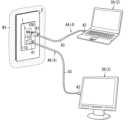
本実施形態に係る配線器具1は、例えば、USBケーブル4の先端に設けられたUSBプラグ(第1接続部)41を接続するためのUSBコンセントに適用される。すなわち、本実施形態に係る配線器具1は、USBコンセントである。配線器具1は、USBケーブル4を介して電気的に接続される外部機器2に対して電力供給、又は外部機器2が備えるバッテリ23(図1参照)の充電を行う。外部機器2は、例えば、パーソナルコンピュータ(PC)、ディスプレイ、スマートフォンのいずれかである。本実施形態では、図1に示すように、第1外部機器2Aは、例えば、パーソナルコンピュータである。また、第2外部機器2Bは、例えば、ディスプレイである。また、図2に示すように、本実施形態に係る配線器具1は、例えば、建物の壁面W1に取り付けられる屋内用の配線器具である。配線器具1が設置される建物は、例えば、戸建住宅又は集合住宅の各住戸のような住宅、或いは、事務所、店舗、工場又は介護施設のような非住宅である。The
配線器具1は、配線器具1に対して電線を電気的に接続した状態で、施工面W1に取り付けられる。施工面W1は、上述したように、建物の壁面W1である。配線器具1においては、図2に示すように、筐体100の前面に形成された挿通孔110にUSBケーブル4のUSBプラグ41を差し込むことによってUSBプラグ41が電気的に接続され、配線器具1から外部機器2への電力供給等が可能になる。ここで、配線器具1は、埋込型の配線器具であって、取付枠を用いて施工面W1に取り付けられる。より具体的には、配線器具1が取り付けられた取付枠を、例えば、埋込ボックスに対して固定することにより、配線器具1が施工面W1に取り付けられる。ここでいう埋込ボックスは、前面が開放された箱状の部材であって、施工面W1に形成された施工孔から前面を前方に露出させるように、壁内に設置される。また、本実施形態に係る配線器具1では、図2に示すように、配線器具1の機能面(挿通孔110が形成されている筐体100の前面)を露出させた状態で、化粧プレート5が取り付けられている。The
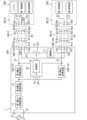
本実施形態に係る配線器具1は、図1に示すように、複数の器具側接続部10を備えている。複数の器具側接続部10は、複数の機器側接続部20が接続可能である。複数の機器側接続部20は、複数の外部機器2にそれぞれ設けられている。複数の器具側接続部10の各々は、給電端子101と、(第2)信号端子103と、を有している。給電端子101は、複数の外部機器2のうちいずれか1つの外部機器2に電力を供給する。(第2)信号端子103は、複数の外部機器2間で信号を伝送するための伝送路53に接続されている。複数の(第2)信号端子103は、伝送路53を介して互いに接続可能である。The
本実施形態に係る配線器具1では、上述したように、複数の給電端子101を介して複数の外部機器2に電力を供給することが可能である。また、配線器具1では、上述したように、複数の(第2)信号端子103が伝送路53を介して互いに接続可能である。したがって、本実施形態に係る配線器具1によれば、複数の外部機器2に給電可能で、かつ複数の外部機器2間で通信を行うことが可能となる。As described above, the
(2)詳細
次に、本実施形態に係る配線器具1、及び当該配線器具1に接続される複数の外部機器2の構成について、図1を参照して説明する。 (2) Details Next, the configuration of the
以下の説明において、複数の外部機器2を区別する必要がある場合には、複数の外部機器2の各々を、「第1外部機器2A、第2外部機器2B」ともいう。また、以下の説明において、複数のUSBケーブル4を区別する必要がある場合には、複数のUSBケーブル4の各々を、「第1USBケーブル4A、第2USBケーブル4B」ともいう。また、以下の説明において、複数の器具側接続部10を区別する必要がある場合には、複数の器具側接続部10の各々を、「第1器具側接続部10A、第2器具側接続部10B」ともいう。また、以下の説明において、複数の第3電力変換回路13を区別する必要がある場合には、複数の第3電力変換回路13の各々を、「第3電力変換回路13A、第3電力変換回路13B」ともいう。In the following description, when it is necessary to distinguish between multiple
(2.1)配線器具
本実施形態に係る配線器具1は、図1に示すように、複数(例えば、2つ)の器具側接続部10を備えている。また、配線器具1は、制御部14と、開閉部15と、切替部16と、増幅部17と、を更に備えている。また、配線器具1は、第1電力変換回路11と、第2電力変換回路12と、複数(例えば、2つ)の第3電力変換回路13と、一対の電源端子T1,T2と、を更に備えている。また、配線器具1は、上述の第1電力変換回路11、第2電力変換回路12、複数の第3電力変換回路13、制御部14、開閉部15、切替部16及び増幅部17を収納する筐体100を更に備えている。 (2.1) Wiring Device As shown in Fig. 1, the
筐体100の形状は、例えば、直方体状である。筐体100の一面(前面)には、上述したように、複数(例えば、2つ)の挿通孔110が形成されている。複数の挿通孔110の各々の正面視の形状は矩形状である。The shape of the
複数の器具側接続部10の各々は、例えば、上述のUSBケーブル4のUSBプラグ(第1接続部)41が接続可能なUSBソケットである。具体的には、複数の器具側接続部10の各々は、例えば、USB Type-Cのソケットである。複数の器具側接続部10は、上述したように、複数の外部機器2にそれぞれ設けられている複数の機器側接続部20が接続可能である。複数の器具側接続部10の各々は、給電端子101と、第1信号端子102と、第2信号端子103と、を有している。Each of the multiple appliance-
給電端子101は、複数の外部機器2のうちいずれか1つの外部機器2に電力を供給するための端子である。より具体的には、給電端子101は、複数の外部機器2のうち、器具側接続部10、USBケーブル4及び機器側接続部20を介して接続されている外部機器2に電力を供給する。給電端子101は、第1給電路51を介して第3電力変換回路13の出力端子に接続されている。第1給電路51は、電力系統3からの交流電力(第1電力)を外部機器2に供給するための給電路である。The power supply terminal 101 is a terminal for supplying power to one of the multiple
第1信号端子102は、配線器具1の制御部14と外部機器2の第1制御部21との間で通信を行うための端子である。第1信号端子102は、制御部14に接続されている。The
第2信号端子(信号端子)103は、USBケーブル4を介して配線器具1に接続されている複数の外部機器2間で通信を行うための端子である。第2信号端子103は、複数の外部機器2間で信号を伝送するための伝送路53に接続されている。図1に示すように、伝送路53の途中には開閉スイッチ151(後述する)が設けられており、この開閉スイッチ151を「閉」にすることによって、複数の第2信号端子103間を接続する(導通させる)ことが可能となる。すなわち、本実施形態に係る配線器具1では、複数の第2信号端子103は、伝送路53を介して互いに接続可能である。The second signal terminal (signal terminal) 103 is a terminal for communication between multiple
複数の器具側接続部10の各々は、その機能面(給電端子101、第1信号端子102及び第2信号端子103が露出している面)を筐体100から露出させた状態で筐体100に保持されている。Each of the multiple appliance-
第1電力変換回路11は、例えば、AC/DCコンバータを含む。すなわち、第1電力変換回路11は、電力系統3から印加される交流電圧を直流電圧に変換する機能を有している。第1電力変換回路11は、2つの第1入力端子と、2つの第1出力端子と、を有している。2つの第1入力端子は、一対の電源端子T1,T2を介して電力系統3に接続されている。2つの出力端子は、第2電力変換回路12の2つの第2入力端子に接続されている。第1電力変換回路11は、当該第1電力変換回路11により変換された後の直流電圧を第2電力変換回路12に印加する。The first
第2電力変換回路12は、例えば、絶縁型のDC/DCコンバータを含む。より具体的には、第2電力変換回路12は、例えば、第1電力変換回路11から印加された直流電圧を、当該直流電圧よりも電圧値の高い直流電圧に変換する昇圧チョッパ回路である。第2電力変換回路12は、2つの第2入力端子と、1つの第2出力端子と、を有している。2つの第2入力端子は、第1電力変換回路11の2つの第1出力端子に接続されている。1つの第2出力端子は、複数の第3電力変換回路13の各々の1つの第3入力端子に接続されている。第2電力変換回路12は、当該第2電力変換回路12により変換された後の直流電圧を、複数の第3電力変換回路13の各々に印加する。The second
複数の第3電力変換回路13の各々は、例えば、DC/DCコンバータを含む。より具体的には、複数の第3電力変換回路13の各々は、例えば、第2電力変換回路12から印加された直流電圧を、当該直流電圧よりも電圧値の低い直流電圧に変換する降圧チョッパ回路である。複数の第3電力変換回路13の各々は、1つの第3入力端子と、1つの第3出力端子と、を有している。1つの第3入力端子は、第2電力変換回路12の1つの第2出力端子に接続されている。1つの第3出力端子は、器具側接続部10の給電端子101に接続されている。複数の第3電力変換回路13の各々は、各第3電力変換回路13により変換された後の直流電圧を給電端子101に印加する。ここで、各第3電力変換回路13によって印加される直流電圧の大きさは、接続される外部機器2に応じて決められていればよく、各第3電力変換回路13によって印加される直流電圧の大きさは同じであってもよいし、異なっていてもよい。Each of the multiple third
制御部14は、例えば、1以上のプロセッサ及び1以上のメモリを有するコンピュータシステムにより実現され得る。すなわち、コンピュータシステムの1以上のメモリに記録されたプログラムを、1以上のプロセッサが実行することにより、制御部14として機能する。プログラムは、ここでは制御部14のメモリに予め記録されているが、インターネット等の電気通信回線を通して提供されてもよく、メモリカード等の非一時的記録媒体に記録されて提供されてもよい。制御部14は、例えば、IC(Integrated Circuit)からなる。The
制御部14は、配線器具1の動作を制御する制御回路である。より具体的には、制御部14は、第1電力変換回路11、第2電力変換回路12及び複数の第3電力変換回路13を各別に制御するように構成されている。また、制御部14は、開閉部15及び切替部16を各別に制御するように構成されている。また、制御部14は、通信機能を有しており、外部機器2の第1制御部21と通信するように構成されている。The
開閉部15は、図1に示すように、開閉スイッチ151を有している。開閉スイッチ151は、複数の第2信号端子103間を接続する伝送路53の途中に設けられている。開閉部15は、制御部14からの開閉信号に従って開閉スイッチ151を開閉する。すなわち、開閉スイッチ151は、複数の第2信号端子103間を接続する伝送路53を開閉するためのスイッチであり、制御部14によって制御される。本実施形態に係る配線器具1では、開閉スイッチ151を開閉することによって、複数の第2信号端子103間を接続していない状態と、複数の第2信号端子103間を接続している状態と、を切り替えることが可能となる。制御部14は、例えば、複数の器具側接続部10に複数の機器側接続部20が接続されることをもって開閉スイッチ151を「閉」にする。より具体的には、制御部14は、複数の外部機器2の各々の第1制御部21との間で通信が行えることをもって複数の器具側接続部10に複数の機器側接続部20が接続されていることを検出する。そして、制御部14は、複数の器具側接続部10に複数の機器側接続部20が接続されていることを検出すると、開閉スイッチ151を「閉」にする。本実施形態では、制御部14により開閉制御部が構成されている。As shown in FIG. 1, the opening/
切替部16は、第1給電路51と第2給電路52とを切り替える機能を有している。第1給電路51は、電力系統3からの第1電力を複数の外部機器2に供給するための給電路である。より具体的には、第1給電路51は、電力系統3から供給された交流電力を、第1電力変換回路11、第2電力変換回路12及び第3電力変換回路13によって変換した後の直流電力を複数の外部機器2に供給する。第2給電路52は、複数の外部機器2のうち少なくとも1つの外部機器2からの第2電力を残りの外部機器2に供給するための給電路である。第2給電路52の第1端は、複数の第1給電路51のうち一方の第1給電路51に接続されており、第2給電路52の第2端は、複数の第1給電路51のうち他方の第1給電路51に接続されている。The switching
切替部16は、図1に示すように、第2給電路52を開閉する切替スイッチ161を有している。切替スイッチ161は、第2給電路52の途中に設けられている。切替スイッチ161は、制御部14からの切替信号に従って切替スイッチ161を開閉する。本実施形態に係る配線器具1では、切替スイッチ161を開閉することによって、複数の外部機器2への給電路として第1給電路51を選択する状態と、複数の外部機器2への給電路として第2給電路52を選択する状態と、を切り替えることが可能となる。制御部14は、例えば、電力系統3の停電が検出されたことをもって切替部16を制御し、第1給電路51から第2給電路52に切り替える。より具体的には、制御部14は、外部機器2の第1制御部21(後述する)との通信により外部機器2に電力が供給されていないことをもって電力系統3の停電を検出し、切替部16を制御することにより第1給電路51から第2給電路52に切り替える。制御部14は、電力系統3の停電が検出されるまでは切替部16の切替スイッチ161を「開」とし、電力系統3の停電が検出されると切替部16の切替スイッチ161を「閉」にする。これにより、電力系統3の停電が検出されるまでは複数の第1給電路51によって複数の外部機器2に給電が可能であり、電力系統3の停電が検出されると第2給電路52によって少なくとも1つの外部機器2から残りの外部機器2への給電が可能である。本実施形態では、制御部14により切替制御部が構成されている。As shown in FIG. 1, the switching
増幅部17は、複数の第2信号端子103を接続する伝送路53の途中に設けられている。増幅部17は、例えば、リドライバICで構成されている。増幅部17は、伝送路53を通過する信号を増幅させる機能を有している。ここで、本実施形態に係る配線器具1では、図1及び図2に示すように、複数の外部機器2は、複数のUSBケーブル4及び配線器具1(の伝送路53)を介して互いに接続される。そのため、伝送路53を含む信号経路が長くなってしまい、当該信号経路を通過する信号が減衰する可能性がある。本実施形態に係る配線器具1では、上述したように、伝送路53の途中に増幅部17を設けている。そのため、伝送路53を含む信号経路が長くなった場合でも、増幅部17によって信号の劣化(減衰)を抑制することが可能となる。The
(2.2)外部機器
本実施形態では、上述したように、配線器具1に対して複数の外部機器2が接続可能である。第1外部機器2Aは、例えば、パーソナルコンピュータである。第1外部機器2Aは、図1に示すように、機器側接続部20と、第1制御部21と、第2制御部22と、バッテリ23と、を備えている。また、第1外部機器2Aは、第1制御部21、第2制御部22及びバッテリ23を収納する筐体200を更に備えている。 (2.2) External Device In the present embodiment, as described above, a plurality of
機器側接続部20は、例えば、USBケーブル4のUSBプラグ(第2接続部)42が接続可能なUSBソケットである。具体的には、複数の機器側接続部20の各々は、例えば、USB Type-Cのソケットである。機器側接続部20は、図1に示すように、受電端子201と、第1信号端子202と、第2信号端子203と、を有している。The device-side connection unit 20 is, for example, a USB socket to which the USB plug (second connection unit) 42 of the
受電端子201は、配線器具1から供給される電力(直流電力)を受け取るための端子である。受電端子201は、バッテリ23に接続されている。第1信号端子202は、配線器具1の制御部14と外部機器2の第1制御部21との間で通信を行うための端子である。第1信号端子202は、第1制御部21に接続されている。第2信号端子203は、USBケーブル4を介して配線器具1に接続されている複数の外部機器2間で通信を行うための端子である。第2信号端子203は、第2制御部22に接続されている。機器側接続部20は、その機能面(受電端子201、第1信号端子202及び第2信号端子203が露出している面)を筐体200から露出させた状態で筐体200に保持されている。The
第1制御部21及び第2制御部22の各々は、例えば、1以上のプロセッサ及び1以上のメモリを有するコンピュータシステムにより実現され得る。すなわち、コンピュータシステムの1以上のメモリに記録されたプログラムを、1以上のプロセッサが実行することにより、第1制御部21又は第2制御部22として機能する。プログラムは、ここでは第1制御部21及び第2制御部22のメモリに予め記録されているが、インターネット等の電気通信回線を通して提供されてもよく、メモリカード等の非一時的記録媒体に記録されて提供されてもよい。Each of the
第1制御部21及び第2制御部22の各々は、第1外部機器2Aの動作を制御する制御回路である。第2制御部22は、例えば、第1外部機器2Aにおける画像表示を担うグラフィックコントローラ(Graphics Controller)である。第1制御部21は、例えば、第1外部機器2Aにおいて第2制御部22が担う画像表示以外の機能を担うコントローラである。第1制御部21は、通信機能を有しており、配線器具1と第1外部機器2Aとの間をUSBケーブル4で接続することによって、配線器具1の制御部14と通信可能である。また、第2制御部22は、通信機能を有しており、配線器具1と第1外部機器2A及び第2外部機器2Bとの間をそれぞれUSBケーブル4で接続することによって、第2外部機器2Bの第2制御部22と通信可能である。Each of the
バッテリ23は、例えば、リチウムイオン電池のような二次電池を含む。バッテリ23は、USBケーブル4を介して配線器具1から供給される直流電力を二次電池に蓄積させる。バッテリ23の二次電池に蓄積させた直流電力は、電力系統3の停電時において、第1制御部21及び第2制御部22等に供給される。また、本実施形態では、バッテリ23の二次電池に蓄積させた直流電力を、配線器具1を介して第2外部機器2Bに供給することも可能である。The battery 23 includes a secondary battery such as a lithium ion battery. The battery 23 stores DC power supplied from the
第2外部機器2Bは、例えば、ディスプレイである。第2外部機器2Bは、図1に示すように、機器側接続部20と、第1制御部21と、第2制御部22と、を備えている。また、第2外部機器2Bは、第1制御部21及び第2制御部22を収納する筐体200を更に備えている。ここで、機器側接続部20は、上述した第1外部機器2Aの機器側接続部20から受電端子201を省略した構成であるため、ここでは説明を省略する。また、第1制御部21及び第2制御部22についても、上述した第1外部機器2Aの第1制御部21及び第2制御部22と同様であり、ここでは説明を省略する。機器側接続部20は、上述した第1外部機器2Aと同様、その機能面を筐体200から露出させた状態で筐体200に保持されている。The second
(2.3)USBケーブル
複数のUSBケーブル4の各々は、配線器具1に対して外部機器2を接続するためのケーブルである。複数のUSBケーブル4の各々は、第1接続部41と、第2接続部42と、ケーブル43と、を備えている。 (2.3) USB Cable Each of the plurality of
第1接続部41は、例えば、USBプラグである。第1接続部41は、例えば、配線器具1の器具側接続部10(USBソケット)に接続可能である。第1接続部41は、図1に示すように、第1端子411と、第2端子412と、第3端子413と、を有している。第1端子411は、器具側接続部10の給電端子101に対応する端子である。第2端子412は、器具側接続部10の第1信号端子102に対応する端子である。第3端子413は、器具側接続部10の第2信号端子103に対応する端子である。The
第2接続部42は、第1接続部41と同様、例えば、USBプラグである。第2接続部42は、例えば、外部機器2の機器側接続部20(USBソケット)に接続可能である。第2接続部42は、図1に示すように、第1端子421と、第2端子422と、第3端子423と、を有している。第1端子421は、機器側接続部20の受電端子201に対応する端子である。第2端子422は、機器側接続部20の第1信号端子202に対応する端子である。第3端子423は、機器側接続部20の第2信号端子203に対応する端子である。The
ケーブル43は、第1接続部41と第2接続部42とを接続するケーブルである。ケーブル43は、第1芯線と、第2芯線と、第3芯線と、を含む。第1芯線は、第1接続部41の第1端子411と第2接続部42の第1端子421とを接続する。第2芯線は、第1接続部41の第2端子412と第2接続部42の第2端子422とを接続する。第3芯線は、第1接続部41の第3端子413と第2接続部42の第3端子423とを接続する。The
USBケーブル4の第1接続部41を配線器具1の器具側接続部10に接続し、USBケーブル4の第2接続部42を外部機器2の機器側接続部20に接続することによって、配線器具1から複数の外部機器2への給電が可能となる。また、USBケーブル4の第1接続部41を配線器具1の器具側接続部10に接続し、USBケーブル4の第2接続部42を外部機器2の機器側接続部20に接続することによって、第1外部機器2Aと第2外部機器2Bとの間で通信が可能となる。By connecting the
(3)動作
(3.1)第1動作
まず、本実施形態に係る配線器具1の第1動作について説明する。第1動作は、複数(例えば、2つ)の外部機器2が配線器具1に接続されることをもって開閉スイッチ151を「閉」にする動作である。 (3) Operation (3.1) First Operation First, a first operation of the
まず、第1USBケーブル4Aを用いて配線器具1と第1外部機器2Aとを接続する。このとき、第1USBケーブル4Aの第1接続部41が配線器具1の第1器具側接続部10Aに接続され、かつ第1USBケーブル4Aの第2接続部42が第1外部機器2Aの機器側接続部20に接続される。First, the
次に、第2USBケーブル4Bを用いて配線器具1と第2外部機器2Bとを接続する。このとき、第2USBケーブル4Bの第1接続部41が配線器具1の第2器具側接続部10Bに接続され、かつ第2USBケーブル4Bの第2接続部42が第2外部機器2Bの機器側接続部20に接続される。Next, the
配線器具1の制御部14は、USBケーブル4を介して各外部機器2の第1制御部21との間で通信が行えることをもって各機器側接続部20が対応する器具側接続部10に接続されていることを検出し、開閉部15の開閉スイッチ151を「閉」にする。これにより、複数の第2信号端子103間が導通することとなり、第1外部機器2A(の第2制御部22)と第2外部機器2B(の第2制御部22)との間で通信を行うことが可能となる。The
(3.2)第2動作
次に、本実施形態に係る配線器具1の第2動作について説明する。第2動作は、電力系統3の停電時に、第1外部機器2Aから第2外部機器2Bに電力を供給できるように、第1給電路51から第2給電路52に切り替える動作である。ここでは、電力系統3の停電時において、配線器具1の制御部14の動作電源が第1外部機器2Aのバッテリ23から供給されることとして説明する。 (3.2) Second Operation Next, a second operation of the
電力系統3の停電が発生する以前では、切替部16の切替スイッチ161は「開」になっており、各外部機器2への給電路として第1給電路51が選択されている。したがって、この場合には、第1電力変換回路11、第2電力変換回路12及び第3電力変換回路13により変換された後の直流電力が第1給電路51を介して各外部機器2に供給される。Before a power outage occurs in the power system 3, the
電力系統3の停電が発生すると、配線器具1から各外部機器2への給電が停止される。第1外部機器2Aでは、バッテリ23を備えているため、バッテリ23から第1制御部21に電力が供給される。第1制御部21は、配線器具1からの給電が停止していることをもって電力系統3の停電が発生したことを検出する。第1制御部21は、電力系統3の停電を検出すると、配線器具1の制御部14に対してバッテリ23からの給電を開始する。When a power outage occurs in the power system 3, the power supply from the
配線器具1では、制御部14は、第2電力変換回路12の出力電圧を監視しており、第2電力変換回路12の出力電圧がゼロになったことをもって電力系統3の停電を検出する。そして、制御部14は、第1外部機器2Aから第2外部機器2Bに対して給電可能なように切替部16の切替スイッチ161を「閉」にし、第2外部機器2Bへの給電路を第1給電路51から第2給電路52に切り替える。これにより、第2給電路52を介して、第1外部機器2Aのバッテリ23から第2外部機器2Bへの給電が可能になる。つまり、本実施形態に係る配線器具1によれば、電力系統3の停電が発生した場合でも、配線器具1を介して、バッテリ23を備えている第1外部機器2Aから、バッテリを備えていない第2外部機器2Bへの給電が可能となる。In the
電力系統3が復電すると、制御部14は、第2電力変換回路12の出力電圧が閾値電圧以上になったことをもって電力系統3の復電を検出する。制御部14は、電力系統3の復電を検出すると、第1外部機器2A及び第2外部機器2Bの各々への給電が可能となるように切替部16の切替スイッチ161を「開」にする。これにより、第2給電路52から第1給電路51に切り替えられる。When power is restored to the power system 3, the
(4)効果
本実施形態に係る配線器具1は、上述したように、複数の器具側接続部10を備えている。複数の器具側接続部10は、複数の機器側接続部20が接続可能である。複数の機器側接続部20は、複数の外部機器2にそれぞれ設けられている。複数の器具側接続部10の各々は、給電端子101と、(第2)信号端子103と、を有している。給電端子101は、複数の外部機器2のうちいずれか1つの外部機器2に電力を供給する。(第2)信号端子103は、複数の外部機器2間で信号を伝送するための伝送路53に接続されている。複数の(第2)信号端子103は、伝送路53を介して互いに接続可能である。 (4) Effects As described above, the
本実施形態に係る配線器具1では、上述したように、複数の器具側接続部10がそれぞれ有する複数の給電端子101により複数の外部機器2に電力を供給することが可能である。また、配線器具1では、上述したように、複数の(第2)信号端子103が伝送路53を介して互いに接続可能である。したがって、本実施形態に係る配線器具1によれば、複数の外部機器2に給電可能で、かつ複数の外部機器2間で通信を行うことが可能となる。As described above, the
また、本実施形態に係る配線器具1では、上述したように、第1給電路51と第2給電路52とを切り替える切替部16を更に備えている。そのため、例えば、電力系統3の停電時においても、第2給電路52を介して、少なくとも1つの外部機器2(本実施形態では第1外部機器2A)から残りの外部機器2(本実施形態では第2外部機器2B)に給電することが可能となる。As described above, the
また、本実施形態に係る配線器具1では、上述したように、増幅部17を更に備えている。そのため、本実施形態に係る配線器具1のように、複数(例えば、2つ)のUSBケーブル4を介して信号を伝送する場合、すなわち伝送路53を含む信号経路の長さが長い場合でも、信号の劣化(減衰)を抑制することが可能となる。As described above, the
(5)変形例
上述の実施形態は、本開示の様々な実施形態の一つに過ぎない。上述の実施形態は、本開示の目的を達成できれば、設計等に応じて種々の変更が可能である。以下、上述の実施形態の変形例を列挙する。以下に説明する変形例は、適宜組み合わせて適用可能である。 (5) Modifications The above-described embodiment is merely one of various embodiments of the present disclosure. The above-described embodiment can be modified in various ways depending on the design, etc., as long as the object of the present disclosure can be achieved. Modifications of the above-described embodiment are listed below. The modifications described below can be applied in appropriate combination.
(5.1)変形例1
変形例1に係る配線器具1Aについて、図3を参照して説明する。 (5.1)
A wiring accessory 1A according to the first modification will be described with reference to FIG.
変形例1では、配線器具1Aに接続される複数の外部機器2がオペレーティングシステム(以下、「OS」ともいう)を含む同種の機器である点で、上述の実施形態と相違する。また、変形例1に係る配線器具1Aでは、制御部14Aが設定部141を有している点で、上述の実施形態に係る配線器具1と相違する。なお、変形例1では、それ以外の構成については上述の実施形態と同様であり、同一の構成要素には同一の符号を付して説明を省略する。
変形例1に係る配線器具1Aは、制御部14Aを備えている。制御部14Aは、設定部141を有している。設定部141は、複数の外部機器2のうち少なくとも1つの外部機器2を除く残りの外部機器2を仮想ドライブとして設定する。The wiring device 1A according to the first modification includes a control unit 14A. The control unit 14A has a setting unit 141. The setting unit 141 sets the remaining
変形例1では、配線器具1に対して第1外部機器2A及び第2外部機器2Bを接続可能である。第1外部機器2A及び第2外部機器2Bの各々は、例えば、パーソナルコンピュータである。すなわち、複数の外部機器2の各々は、OSを含む同種の機器である。本開示でいう「同種の機器」は、同じOSが搭載されている機器を意味する。例えば、第1外部機器2AのOSがWindows(登録商標)であれば、第2外部機器2BのOSもWindows(登録商標)である。In the first modification, a first
変形例1のように、第1外部機器2Aと第2外部機器2BとがOSを含む同種の機器である場合、配線器具1Aの制御部14Aの設定部141は、第1外部機器2Aと第2外部機器2Bとの接続を有効化するために、第1外部機器2Aと第2外部機器2Bとの一方を仮想ドライブとして設定する。本実施形態では一例として、設定部141は、第1器具側接続部10Aを介して配線器具1Aに接続されている第1外部機器2Aをホスト、第2器具側接続部10Bを介して配線器具1Aに接続されている第2外部機器2Bをデバイスに設定する。そして、設定部141は、デバイスに設定されている第2外部機器2Bを仮想ドライブとして設定する。これにより、第1外部機器2Aと第2外部機器2Bとの間で相互に通信を行うことが可能となる。As in the first modification, when the first
変形例1では、第2器具側接続部10Bを介して配線器具1Aに接続されている第2外部機器2Bをデバイスとし、仮想ドライブとして設定しているが、これに限らない。設定部141は、複数の外部機器2に対してホストとデバイスとを入れ替えることが可能で、複数の外部機器2のうちデバイスに設定されている外部機器2を仮想ドライブとして設定してもよい。例えば、設定部141は、第1外部機器2Aがホスト、第2外部機器2Bがデバイスに設定されていれば、第2外部機器2Bを仮想ドライブとして設定する。また、設定部141は、第1外部機器2Aがデバイス、第2外部機器2Bがホストに設定されていれば、第1外部機器2Aを仮想ドライブとして設定する。これにより、第1外部機器2Aと第2外部機器2Bとの間で相互に通信を行うことが可能となる。In the first modification, the second
変形例1では、第1外部機器2A及び第2外部機器2Bの各々がパーソナルコンピュータであるが、これに限らない。第1外部機器2A及び第2外部機器2Bの各々は、OSを含む同種の機器であればよく、例えば、スマートフォンであってもよいし、デジタルカメラであってもよい。これらの場合においても、設定部141は、複数の外部機器2のうちデバイスに設定されている外部機器2を仮想ドライブとして設定すればよい。これにより、第1外部機器2Aと第2外部機器2Bとの間で相互に通信を行うことが可能となる。In the first modification, each of the first
(5.2)その他の変形例
以下、その他の変形例を列挙する。 (5.2) Other Modifications Other modifications are listed below.
上述の実施形態では、配線器具1がUSBコンセントであるが、配線器具1は、例えば、コンセントタップ、壁コンセント、什器用コンセント、OAタップ(電源タップ)及び充電アダプタ(ACアダプタ)のいずれかであってもよい。In the above embodiment, the
上述の実施形態では、複数の信号端子103間を接続する伝送路53の途中に、伝送路53を開閉する開閉スイッチ151が設けられているが、開閉スイッチ151は省略されてもよい。すなわち、複数の信号端子103は、伝送路53を介して互いに常時接続されていてもよい。この構成によれば、複数の信号端子103間を開閉する構成(開閉スイッチ151)が不要であり、配線器具1の簡略化を図ることが可能となる。In the above embodiment, an open/
上述の実施形態では、複数の器具側接続部10の各々がUSB Type-Cのソケットであるが、例えば、USB Type-Aのソケットであってもよいし、USB Type-Bのソケットであってもよい。また、上述の実施形態では、複数の機器側接続部20の各々がUSB Type-Cのソケットであるが、例えば、USB Type-Aのソケットであってもよいし、USB Type-Bのソケットであってもよい。In the above embodiment, each of the multiple appliance
上述の実施形態では、2つの器具側接続部10が配線器具1に設けられているが、器具側接続部10の個数は2つに限らず、3つ以上であってもよい。この場合、制御部14は、3つ以上の器具側接続部10のうち機器側接続部20が接続されている器具側接続部10の個数に合わせて、複数の伝送路53の中から対応する伝送路53を選択するように構成されていることが好ましい。In the above embodiment, two tool-
上述の実施形態では、第2信号端子103が1つであるが、第2信号端子103は、例えば、複数であってもよい。この場合、複数の伝送路53は、1つの開閉部15にて開閉するようになっていてもよいし、一対一に対応する複数の開閉部15にて開閉するようになっていてもよい。In the above embodiment, there is one
上述の実施形態では、切替部16と増幅部17とが別々に設けられているが、切替部16と増幅部17とが一体に設けられていてもよい。すなわち、増幅部17を構成するリドライバICに切替部16としての機能が含まれていてもよい。In the above embodiment, the switching
上述の実施形態では、第1外部機器2Aが備えるバッテリ23が二次電池を含んでいるが、これに限らない。バッテリ23は、例えば、一次電池を含んでいてもよいし、電気二重層コンデンサ(EDLC;Electric Double-Layer Capacitor)を含んでいてもよい。In the above embodiment, the battery 23 provided in the first
上述の実施形態では、電力系統3の停電時において、第1外部機器2Aのバッテリ23から配線器具1の制御部14の動作電源を供給しているが、配線器具1は、例えば、二次電池を備えていてもよい。これにより、電力系統3の停電時において二次電池から制御部14に電力を供給することが可能となる。In the above embodiment, when the power grid 3 experiences a power outage, the battery 23 of the first
上述の実施形態では、制御部14は、複数の外部機器2の第1制御部21との間で通信が行えることをもって複数の器具側接続10に複数の機器側接続部20が接続されていることを検出しているが、これに限らない。制御部14は、例えば、器具側接続部10に検出スイッチを設け、この検出スイッチにて器具側接続部10に機器側接続部20が接続されていることを検出してもよい。In the above embodiment, the
上述の実施形態では、第1外部機器2Aがパーソナルコンピュータで、第2外部機器2Bがディスプレイであるが、例えば、第1外部機器2Aがパーソナルコンピュータで、第2外部機器2Bがスマートフォンであってもよい。さらに、第1外部機器2Aがパーソナルコンピュータで、第2外部機器2Bがマウスであってもよい。In the above embodiment, the first
上述の実施形態では、制御部14は、第2電力変換回路12の出力電圧によって電力系統3の停電及び復電を検出しているが、例えば、第1外部機器2Aの第1制御部21との通信によって電力系統3の停電及び復電を検出してもよい。In the above embodiment, the
(態様)
以上説明した実施形態及び変形例等から以下の態様が開示されている。 (Aspects)
The following aspects are disclosed from the above-described embodiment and modified examples.
第1の態様に係る配線器具(1;1A)は、複数の器具側接続部(10)を備える。複数の器具側接続部(10)は、複数の機器側接続部(20)が接続可能である。複数の機器側接続部(20)は、複数の外部機器(2)にそれぞれ設けられている。複数の器具側接続部(10)の各々は、給電端子(101)と、信号端子(103)と、を有する。給電端子(101)は、複数の外部機器(2)のうちいずれか1つの外部機器(2)に電力を供給する。信号端子(103)は、複数の外部機器(2)間で信号を伝送するための伝送路(53)に接続されている。複数の信号端子(103)は、伝送路(53)を介して互いに接続可能である。The wiring device (1; 1A) according to the first aspect includes a plurality of device-side connection parts (10). A plurality of device-side connection parts (20) can be connected to the plurality of device-side connection parts (10). The plurality of device-side connection parts (20) are provided on the plurality of external devices (2). Each of the plurality of device-side connection parts (10) has a power supply terminal (101) and a signal terminal (103). The power supply terminal (101) supplies power to any one of the plurality of external devices (2). The signal terminal (103) is connected to a transmission path (53) for transmitting signals between the plurality of external devices (2). The plurality of signal terminals (103) can be connected to each other via the transmission path (53).
この態様によれば、複数の外部機器(2)に給電可能で、かつ複数の外部機器(2)間で通信を行うことが可能となる。According to this embodiment, it is possible to supply power to multiple external devices (2) and to communicate between the multiple external devices (2).
第2の態様に係る配線器具(1;1A)は、第1の態様において、開閉スイッチ(151)と、開閉制御部(14;14A)と、を更に備える。開閉スイッチ(151)は、伝送路(53)を開閉する。開閉制御部(14;14A)は、開閉スイッチ(151)を制御する。The wiring device (1; 1A) according to the second aspect further includes an open/close switch (151) and an open/close control unit (14; 14A) in the first aspect. The open/close switch (151) opens and closes the transmission line (53). The open/close control unit (14; 14A) controls the open/close switch (151).
この態様によれば、伝送路(53)を開閉することが可能となる。According to this embodiment, it is possible to open and close the transmission path (53).
第3の態様に係る配線器具(1;1A)では、第2の態様において、開閉制御部(14;14A)は、複数の機器側接続部(20)のうち少なくとも2つの機器側接続部(20)が複数の器具側接続部(10)のうち少なくとも2つの器具側接続部(10)に接続されると、開閉スイッチ(151)を閉にする。In the wiring device (1; 1A) according to the third aspect, in the second aspect, the opening/closing control unit (14; 14A) closes the opening/closing switch (151) when at least two of the multiple device side connection parts (20) are connected to at least two of the multiple device side connection parts (10).
この態様によれば、少なくとも2つの機器側接続部(20)が少なくとも2つの器具側接続部(10)に接続されることをもって開閉スイッチ(151)を閉にすることが可能となる。According to this embodiment, the opening/closing switch (151) can be closed by connecting at least two device side connection parts (20) to at least two appliance side connection parts (10).
第4の態様に係る配線器具(1;1A)では、第1の態様において、複数の信号端子(103)は、互いに常時接続されている。In the wiring device (1; 1A) according to the fourth aspect, in the first aspect, the multiple signal terminals (103) are constantly connected to each other.
この態様によれば、複数の信号端子(103)間を開閉する構成が不要であり、配線器具(1)の簡素化を図ることが可能となる。According to this embodiment, a configuration for opening and closing multiple signal terminals (103) is not required, making it possible to simplify the wiring device (1).
第5の態様に係る配線器具(1;1A)は、第1~第4の態様のいずれか1つにおいて、切替部(16)を更に備える。切替部(16)は、第1給電路(51)と、第2給電路(52)と、を切り替える。第1給電路(51)は、電力系統(3)からの第1電力を複数の外部機器(2)に供給する。第2給電路(52)は、複数の外部機器(2)のうち少なくとも1つの外部機器(2)からの第2電力を残りの外部機器(2)に供給する。切替部(16)は、電力系統(3)の停電が検出されると第1給電路(51)から第2給電路(52)に切り替える。The wiring device (1; 1A) according to the fifth aspect is any one of the first to fourth aspects, and further includes a switching unit (16). The switching unit (16) switches between a first power supply path (51) and a second power supply path (52). The first power supply path (51) supplies a first power from the power system (3) to a plurality of external devices (2). The second power supply path (52) supplies a second power from at least one of the plurality of external devices (2) to the remaining external devices (2). The switching unit (16) switches from the first power supply path (51) to the second power supply path (52) when a power outage in the power system (3) is detected.
この態様によれば、電力系統(3)の停電時においても外部機器(2)に対して電力を供給することが可能となる。According to this embodiment, it is possible to supply power to the external device (2) even during a power outage in the power grid (3).
第6の態様に係る配線器具(1;1A)では、第5の態様において、切替部(16)を制御する切替制御部(14;14A)を更に備える。切替部(16)は、第2給電路(52)を開閉する切替スイッチ(161)を有する。切替制御部(14;14A)は、電力系統(3)の停電が検出されるまでは切替スイッチ(161)を開にする。切替制御部(14;14A)は、電力系統(3)の停電が検出されると切替スイッチ(161)を閉にする。The wiring device (1; 1A) according to the sixth aspect further includes a switching control unit (14; 14A) that controls the switching unit (16) in the fifth aspect. The switching unit (16) has a switching switch (161) that opens and closes the second power supply path (52). The switching control unit (14; 14A) opens the switching switch (161) until a power outage in the power system (3) is detected. When a power outage in the power system (3) is detected, the switching control unit (14; 14A) closes the switching switch (161).
この態様によれば、電力系統(3)の停電時においても外部機器(2)に対して電力を供給することが可能となる。According to this embodiment, it is possible to supply power to the external device (2) even during a power outage in the power grid (3).
第7の態様に係る配線器具(1;1A)は、第1~第6の態様のいずれか1つにおいて、増幅部(17)を更に備える。増幅部(17)は、伝送路(53)を通る信号を増幅する。The wiring device (1; 1A) according to the seventh aspect is any one of the first to sixth aspects and further includes an amplifier (17). The amplifier (17) amplifies the signal passing through the transmission path (53).
この態様によれば、複数の外部機器(2)間で伝送される信号の劣化を抑制することが可能となる。According to this aspect, it is possible to suppress degradation of signals transmitted between multiple external devices (2).
第8の態様に係る配線器具(1;1A)では、第1~第7の態様のいずれか1つにおいて、複数の外部機器(2)の各々は、オペレーティングシステムを含む同種の機器である。配線器具(1;1A)は、設定部(141)を更に備える。設定部(141)は、複数の外部機器(2)のうち少なくとも1つの外部機器(2)を除いた残りの外部機器(2)を仮想ドライブとして設定する。In the wiring device (1; 1A) according to the eighth aspect, in any one of the first to seventh aspects, each of the multiple external devices (2) is a homogeneous device including an operating system. The wiring device (1; 1A) further includes a setting unit (141). The setting unit (141) sets the remaining external devices (2) excluding at least one external device (2) among the multiple external devices (2) as virtual drives.
この態様によれば、複数の外部機器(2)間で相互に通信を行うことが可能となる。According to this embodiment, it becomes possible for multiple external devices (2) to communicate with each other.
第9の態様に係る配線器具(1;1A)は、第1~第8の態様のいずれか1つにおいて、USBコンセントである。The wiring device (1; 1A) according to the ninth aspect is a USB outlet in any one of the first to eighth aspects.
この態様によれば、複数の外部機器(2)に給電可能で、かつ複数の外部機器(2)間で通信を行うことが可能なUSBコンセントを実現することが可能となる。According to this aspect, it is possible to realize a USB outlet that can supply power to multiple external devices (2) and can communicate between multiple external devices (2).
第2~第9の態様に係る構成については、配線器具(1;1A)に必須の構成ではなく、適宜省略可能である。The configurations according to the second to ninth aspects are not essential to the wiring device (1; 1A) and may be omitted as appropriate.
1,1A 配線器具
2 外部機器
3 電力系統
10 器具側接続部
14,14A 制御部(開閉制御部、切替制御部)
16 切替部
17 増幅部
20 機器側接続部
51 第1給電路
52 第2給電路
53 伝送路
101 給電端子
103 第2信号端子(信号端子)
141 設定部
151 開閉スイッチ
161 切替スイッチ1,
16
141
Claims (6)
Translated fromJapanese前記複数の外部機器間で信号を伝送するための伝送路を開閉する開閉スイッチと、
前記開閉スイッチを制御する開閉制御部と、を備え、
前記複数の器具側接続部の各々は、
前記複数の外部機器のうちいずれか1つの外部機器に電力を供給する給電端子と、
前記伝送路に接続されている信号端子と、を有し、
複数の前記信号端子は、前記伝送路を介して互いに接続可能であり、
前記開閉制御部は、前記複数の機器側接続部のうち少なくとも2つの機器側接続部が前記複数の器具側接続部のうち少なくとも2つの器具側接続部に接続されると、前記開閉スイッチを閉にする、
配線器具。 A plurality of device-side connectorsto which a plurality of device-side connectors respectively provided on a plurality of external devices can be connected;
an open/close switch for opening and closing a transmission path for transmitting signals between the plurality of external devices;
An opening/closing control unit that controls the opening/closing switch,
Each of the plurality of appliance side connection parts is
a power supply terminal for supplying power to any one of the plurality of external devices;
a signal terminal connected tothe transmission line;
the signal terminalsare connectable to each other via the transmission path,
the opening/closing control unit closes the opening/closing switch when at least two of the plurality of device-side connection parts are connected to at least two of the plurality of appliance-side connection parts;
Wiring equipment.
前記切替部は、前記電力系統の停電が検出されると前記第1給電路から前記第2給電路に切り替える、The switching unit switches from the first power supply path to the second power supply path when a power outage in the power grid is detected.
請求項1に記載の配線器具。The wiring device according to claim 1 .
前記切替部は、前記第2給電路を開閉する切替スイッチを有し、The switching unit has a changeover switch that opens and closes the second power supply path,
前記切替制御部は、The switching control unit is
前記電力系統の前記停電が検出されるまでは前記切替スイッチを開にし、The changeover switch is opened until the power outage of the power grid is detected;
前記電力系統の前記停電が検出されると前記切替スイッチを閉にする、When the power outage in the power grid is detected, the changeover switch is closed.
請求項2に記載の配線器具。The wiring device according to claim 2.
請求項1~3のいずれか1項に記載の配線器具。The wiring device according to any one of claims 1 to 3.
前記複数の外部機器のうち少なくとも1つの外部機器を除いた残りの外部機器を仮想ドライブとして設定する設定部を更に備える、a setting unit that sets the remaining external devices, excluding at least one external device, among the plurality of external devices as virtual drives;
請求項1~4のいずれか1項に記載の配線器具。The wiring device according to any one of claims 1 to 4.
請求項1~5のいずれか1項に記載の配線器具。The wiring device according to any one of claims 1 to 5.
Priority Applications (3)
| Application Number | Priority Date | Filing Date | Title |
|---|---|---|---|
| JP2020185361AJP7550363B2 (en) | 2020-11-05 | 2020-11-05 | Wiring devices |
| PCT/JP2021/039679WO2022097554A1 (en) | 2020-11-05 | 2021-10-27 | Wiring implement |
| TW110141049ATWI806219B (en) | 2020-11-05 | 2021-11-04 | Wiring device |
Applications Claiming Priority (1)
| Application Number | Priority Date | Filing Date | Title |
|---|---|---|---|
| JP2020185361AJP7550363B2 (en) | 2020-11-05 | 2020-11-05 | Wiring devices |
Publications (2)
| Publication Number | Publication Date |
|---|---|
| JP2022074924A JP2022074924A (en) | 2022-05-18 |
| JP7550363B2true JP7550363B2 (en) | 2024-09-13 |
Family
ID=81457849
Family Applications (1)
| Application Number | Title | Priority Date | Filing Date |
|---|---|---|---|
| JP2020185361AActiveJP7550363B2 (en) | 2020-11-05 | 2020-11-05 | Wiring devices |
Country Status (3)
| Country | Link |
|---|---|
| JP (1) | JP7550363B2 (en) |
| TW (1) | TWI806219B (en) |
| WO (1) | WO2022097554A1 (en) |
Citations (6)
| Publication number | Priority date | Publication date | Assignee | Title |
|---|---|---|---|---|
| JP2011008585A (en) | 2009-06-26 | 2011-01-13 | Buffalo Inc | Computer device, computer processing method and computer program |
| JP2013229259A (en) | 2012-04-06 | 2013-11-07 | Kyohaya Technology Ltd | Wall-type usb charging hub socket |
| JP2014229936A (en) | 2013-05-17 | 2014-12-08 | 富士通株式会社 | Relay device and relay method |
| JP2015122642A (en) | 2013-12-24 | 2015-07-02 | ルネサスエレクトロニクス株式会社 | Semiconductor device and serial data transmission line system |
| JP2016192829A (en) | 2015-03-30 | 2016-11-10 | 大和ハウス工業株式会社 | Power supply system for multiple dwelling |
| JP2019096282A (en) | 2016-11-23 | 2019-06-20 | 宸定科技股▲ふん▼有限公司SIM Power Technology Inc. | Hub |
Family Cites Families (4)
| Publication number | Priority date | Publication date | Assignee | Title |
|---|---|---|---|---|
| JP2008288164A (en)* | 2007-05-21 | 2008-11-27 | Panasonic Electric Works Co Ltd | Information outlet and multimedia wiring device using the same |
| JP5901241B2 (en)* | 2011-11-18 | 2016-04-06 | キヤノン株式会社 | USB hub device and system using the same |
| US8568152B1 (en)* | 2012-04-19 | 2013-10-29 | Pass & Seymour, Inc. | Shutter assembly for electrical devices |
| JP2014229636A (en)* | 2013-05-17 | 2014-12-08 | リンテック株式会社 | Sheet sticking device and sheet sticking method |
- 2020
- 2020-11-05JPJP2020185361Apatent/JP7550363B2/enactiveActive
- 2021
- 2021-10-27WOPCT/JP2021/039679patent/WO2022097554A1/ennot_activeCeased
- 2021-11-04TWTW110141049Apatent/TWI806219B/enactive
Patent Citations (6)
| Publication number | Priority date | Publication date | Assignee | Title |
|---|---|---|---|---|
| JP2011008585A (en) | 2009-06-26 | 2011-01-13 | Buffalo Inc | Computer device, computer processing method and computer program |
| JP2013229259A (en) | 2012-04-06 | 2013-11-07 | Kyohaya Technology Ltd | Wall-type usb charging hub socket |
| JP2014229936A (en) | 2013-05-17 | 2014-12-08 | 富士通株式会社 | Relay device and relay method |
| JP2015122642A (en) | 2013-12-24 | 2015-07-02 | ルネサスエレクトロニクス株式会社 | Semiconductor device and serial data transmission line system |
| JP2016192829A (en) | 2015-03-30 | 2016-11-10 | 大和ハウス工業株式会社 | Power supply system for multiple dwelling |
| JP2019096282A (en) | 2016-11-23 | 2019-06-20 | 宸定科技股▲ふん▼有限公司SIM Power Technology Inc. | Hub |
Also Published As
| Publication number | Publication date |
|---|---|
| TW202220330A (en) | 2022-05-16 |
| JP2022074924A (en) | 2022-05-18 |
| TWI806219B (en) | 2023-06-21 |
| WO2022097554A1 (en) | 2022-05-12 |
Similar Documents
| Publication | Publication Date | Title |
|---|---|---|
| JP2002330506A (en) | Distribution board, junction box, outlet box, plug with electric cord, terminal box for outlet box, table tap and home network system | |
| US20160172808A1 (en) | Combined audio/video and alternating current (ac) power module | |
| US20170187155A1 (en) | Wiring device with connector integrated into pcb substrate | |
| CN101542343A (en) | Electro-optical plug and socket | |
| US20110210717A1 (en) | Apparatus and Methods for Mapping a Wired Network | |
| TWM308574U (en) | Household self-provided power supply | |
| JP2017513441A (en) | Electric multimode power converter module and power system | |
| JP7550363B2 (en) | Wiring devices | |
| US9000609B2 (en) | Extension cord with AC and DC outputs for coupling AC and DC sources | |
| TWI450588B (en) | Plug and play network digital image display and video surveillance system | |
| US20250015545A1 (en) | Power track system with leakage current protection function | |
| CN207926615U (en) | Dispatch desk and dispatch system | |
| CN102117997A (en) | Intelligent socket and intelligent plug | |
| CN104995802A (en) | Communication module adaptor | |
| US10965149B2 (en) | Electrical power restoration system for a circuit assembly and method | |
| CN101227603A (en) | Plug-and-play network digital image display and image monitoring system | |
| US9627926B2 (en) | Backup power device, system and method of use | |
| RU2546556C2 (en) | Installation mechanism having universal data communication in building system engineering and devices having said installation mechanisms | |
| CN117749537A (en) | An information bridge module for 86 panels | |
| CN218848243U (en) | Comprehensive test bed for industrial control equipment | |
| JP5233519B2 (en) | Electronics | |
| CN220553759U (en) | Function modularization electrical apparatus controlling means and video control box | |
| KR102468961B1 (en) | A power management system of lecture room | |
| JP7617544B2 (en) | USB outlet | |
| JP2021106120A (en) | Usb receptacle |
Legal Events
| Date | Code | Title | Description |
|---|---|---|---|
| A621 | Written request for application examination | Free format text:JAPANESE INTERMEDIATE CODE: A621 Effective date:20230123 | |
| A131 | Notification of reasons for refusal | Free format text:JAPANESE INTERMEDIATE CODE: A131 Effective date:20240319 | |
| A521 | Request for written amendment filed | Free format text:JAPANESE INTERMEDIATE CODE: A523 Effective date:20240520 | |
| TRDD | Decision of grant or rejection written | ||
| A01 | Written decision to grant a patent or to grant a registration (utility model) | Free format text:JAPANESE INTERMEDIATE CODE: A01 Effective date:20240723 | |
| A61 | First payment of annual fees (during grant procedure) | Free format text:JAPANESE INTERMEDIATE CODE: A61 Effective date:20240819 | |
| R150 | Certificate of patent or registration of utility model | Ref document number:7550363 Country of ref document:JP Free format text:JAPANESE INTERMEDIATE CODE: R150 |