JP7549731B2 - Surgery system and method for controlling the surgery system - Google Patents
Surgery system and method for controlling the surgery systemDownload PDFInfo
- Publication number
- JP7549731B2 JP7549731B2JP2023500490AJP2023500490AJP7549731B2JP 7549731 B2JP7549731 B2JP 7549731B2JP 2023500490 AJP2023500490 AJP 2023500490AJP 2023500490 AJP2023500490 AJP 2023500490AJP 7549731 B2JP7549731 B2JP 7549731B2
- Authority
- JP
- Japan
- Prior art keywords
- screen
- treatment target
- surgical system
- marking
- control device
- Prior art date
- Legal status (The legal status is an assumption and is not a legal conclusion. Google has not performed a legal analysis and makes no representation as to the accuracy of the status listed.)
- Active
Links
Images


Classifications
- A—HUMAN NECESSITIES
- A61—MEDICAL OR VETERINARY SCIENCE; HYGIENE
- A61B—DIAGNOSIS; SURGERY; IDENTIFICATION
- A61B1/00—Instruments for performing medical examinations of the interior of cavities or tubes of the body by visual or photographical inspection, e.g. endoscopes; Illuminating arrangements therefor
- A61B1/04—Instruments for performing medical examinations of the interior of cavities or tubes of the body by visual or photographical inspection, e.g. endoscopes; Illuminating arrangements therefor combined with photographic or television appliances
- A61B1/045—Control thereof
- A—HUMAN NECESSITIES
- A61—MEDICAL OR VETERINARY SCIENCE; HYGIENE
- A61B—DIAGNOSIS; SURGERY; IDENTIFICATION
- A61B1/00—Instruments for performing medical examinations of the interior of cavities or tubes of the body by visual or photographical inspection, e.g. endoscopes; Illuminating arrangements therefor
- A61B1/005—Flexible endoscopes
- A61B1/01—Guiding arrangements therefore
- A—HUMAN NECESSITIES
- A61—MEDICAL OR VETERINARY SCIENCE; HYGIENE
- A61B—DIAGNOSIS; SURGERY; IDENTIFICATION
- A61B34/00—Computer-aided surgery; Manipulators or robots specially adapted for use in surgery
- A61B34/20—Surgical navigation systems; Devices for tracking or guiding surgical instruments, e.g. for frameless stereotaxis
- A—HUMAN NECESSITIES
- A61—MEDICAL OR VETERINARY SCIENCE; HYGIENE
- A61B—DIAGNOSIS; SURGERY; IDENTIFICATION
- A61B34/00—Computer-aided surgery; Manipulators or robots specially adapted for use in surgery
- A61B34/25—User interfaces for surgical systems
- A—HUMAN NECESSITIES
- A61—MEDICAL OR VETERINARY SCIENCE; HYGIENE
- A61B—DIAGNOSIS; SURGERY; IDENTIFICATION
- A61B90/00—Instruments, implements or accessories specially adapted for surgery or diagnosis and not covered by any of the groups A61B1/00 - A61B50/00, e.g. for luxation treatment or for protecting wound edges
- A61B90/36—Image-producing devices or illumination devices not otherwise provided for
- A61B90/361—Image-producing devices, e.g. surgical cameras
- A—HUMAN NECESSITIES
- A61—MEDICAL OR VETERINARY SCIENCE; HYGIENE
- A61B—DIAGNOSIS; SURGERY; IDENTIFICATION
- A61B90/00—Instruments, implements or accessories specially adapted for surgery or diagnosis and not covered by any of the groups A61B1/00 - A61B50/00, e.g. for luxation treatment or for protecting wound edges
- A61B90/36—Image-producing devices or illumination devices not otherwise provided for
- A61B90/37—Surgical systems with images on a monitor during operation
- G—PHYSICS
- G06—COMPUTING OR CALCULATING; COUNTING
- G06T—IMAGE DATA PROCESSING OR GENERATION, IN GENERAL
- G06T7/00—Image analysis
- G06T7/0002—Inspection of images, e.g. flaw detection
- G06T7/0012—Biomedical image inspection
- G—PHYSICS
- G06—COMPUTING OR CALCULATING; COUNTING
- G06T—IMAGE DATA PROCESSING OR GENERATION, IN GENERAL
- G06T7/00—Image analysis
- G06T7/70—Determining position or orientation of objects or cameras
- G06T7/73—Determining position or orientation of objects or cameras using feature-based methods
- H—ELECTRICITY
- H04—ELECTRIC COMMUNICATION TECHNIQUE
- H04N—PICTORIAL COMMUNICATION, e.g. TELEVISION
- H04N23/00—Cameras or camera modules comprising electronic image sensors; Control thereof
- H04N23/60—Control of cameras or camera modules
- H04N23/695—Control of camera direction for changing a field of view, e.g. pan, tilt or based on tracking of objects
- A—HUMAN NECESSITIES
- A61—MEDICAL OR VETERINARY SCIENCE; HYGIENE
- A61B—DIAGNOSIS; SURGERY; IDENTIFICATION
- A61B34/00—Computer-aided surgery; Manipulators or robots specially adapted for use in surgery
- A61B34/10—Computer-aided planning, simulation or modelling of surgical operations
- A61B2034/107—Visualisation of planned trajectories or target regions
- A—HUMAN NECESSITIES
- A61—MEDICAL OR VETERINARY SCIENCE; HYGIENE
- A61B—DIAGNOSIS; SURGERY; IDENTIFICATION
- A61B34/00—Computer-aided surgery; Manipulators or robots specially adapted for use in surgery
- A61B34/20—Surgical navigation systems; Devices for tracking or guiding surgical instruments, e.g. for frameless stereotaxis
- A61B2034/2046—Tracking techniques
- A61B2034/2055—Optical tracking systems
- A—HUMAN NECESSITIES
- A61—MEDICAL OR VETERINARY SCIENCE; HYGIENE
- A61B—DIAGNOSIS; SURGERY; IDENTIFICATION
- A61B34/00—Computer-aided surgery; Manipulators or robots specially adapted for use in surgery
- A61B34/20—Surgical navigation systems; Devices for tracking or guiding surgical instruments, e.g. for frameless stereotaxis
- A61B2034/2046—Tracking techniques
- A61B2034/2065—Tracking using image or pattern recognition
- A—HUMAN NECESSITIES
- A61—MEDICAL OR VETERINARY SCIENCE; HYGIENE
- A61B—DIAGNOSIS; SURGERY; IDENTIFICATION
- A61B34/00—Computer-aided surgery; Manipulators or robots specially adapted for use in surgery
- A61B34/20—Surgical navigation systems; Devices for tracking or guiding surgical instruments, e.g. for frameless stereotaxis
- A61B2034/2068—Surgical navigation systems; Devices for tracking or guiding surgical instruments, e.g. for frameless stereotaxis using pointers, e.g. pointers having reference marks for determining coordinates of body points
- A—HUMAN NECESSITIES
- A61—MEDICAL OR VETERINARY SCIENCE; HYGIENE
- A61B—DIAGNOSIS; SURGERY; IDENTIFICATION
- A61B34/00—Computer-aided surgery; Manipulators or robots specially adapted for use in surgery
- A61B34/20—Surgical navigation systems; Devices for tracking or guiding surgical instruments, e.g. for frameless stereotaxis
- A61B2034/2074—Interface software
- A—HUMAN NECESSITIES
- A61—MEDICAL OR VETERINARY SCIENCE; HYGIENE
- A61B—DIAGNOSIS; SURGERY; IDENTIFICATION
- A61B34/00—Computer-aided surgery; Manipulators or robots specially adapted for use in surgery
- A61B34/25—User interfaces for surgical systems
- A61B2034/252—User interfaces for surgical systems indicating steps of a surgical procedure
- A—HUMAN NECESSITIES
- A61—MEDICAL OR VETERINARY SCIENCE; HYGIENE
- A61B—DIAGNOSIS; SURGERY; IDENTIFICATION
- A61B34/00—Computer-aided surgery; Manipulators or robots specially adapted for use in surgery
- A61B34/25—User interfaces for surgical systems
- A61B2034/254—User interfaces for surgical systems being adapted depending on the stage of the surgical procedure
- A—HUMAN NECESSITIES
- A61—MEDICAL OR VETERINARY SCIENCE; HYGIENE
- A61B—DIAGNOSIS; SURGERY; IDENTIFICATION
- A61B34/00—Computer-aided surgery; Manipulators or robots specially adapted for use in surgery
- A61B34/25—User interfaces for surgical systems
- A61B2034/256—User interfaces for surgical systems having a database of accessory information, e.g. including context sensitive help or scientific articles
- A—HUMAN NECESSITIES
- A61—MEDICAL OR VETERINARY SCIENCE; HYGIENE
- A61B—DIAGNOSIS; SURGERY; IDENTIFICATION
- A61B90/00—Instruments, implements or accessories specially adapted for surgery or diagnosis and not covered by any of the groups A61B1/00 - A61B50/00, e.g. for luxation treatment or for protecting wound edges
- A61B90/36—Image-producing devices or illumination devices not otherwise provided for
- A61B2090/363—Use of fiducial points
- A—HUMAN NECESSITIES
- A61—MEDICAL OR VETERINARY SCIENCE; HYGIENE
- A61B—DIAGNOSIS; SURGERY; IDENTIFICATION
- A61B90/00—Instruments, implements or accessories specially adapted for surgery or diagnosis and not covered by any of the groups A61B1/00 - A61B50/00, e.g. for luxation treatment or for protecting wound edges
- A61B90/36—Image-producing devices or illumination devices not otherwise provided for
- A61B2090/364—Correlation of different images or relation of image positions in respect to the body
- A61B2090/365—Correlation of different images or relation of image positions in respect to the body augmented reality, i.e. correlating a live optical image with another image
- A—HUMAN NECESSITIES
- A61—MEDICAL OR VETERINARY SCIENCE; HYGIENE
- A61B—DIAGNOSIS; SURGERY; IDENTIFICATION
- A61B90/00—Instruments, implements or accessories specially adapted for surgery or diagnosis and not covered by any of the groups A61B1/00 - A61B50/00, e.g. for luxation treatment or for protecting wound edges
- A61B90/36—Image-producing devices or illumination devices not otherwise provided for
- A61B90/37—Surgical systems with images on a monitor during operation
- A61B2090/372—Details of monitor hardware
- A—HUMAN NECESSITIES
- A61—MEDICAL OR VETERINARY SCIENCE; HYGIENE
- A61B—DIAGNOSIS; SURGERY; IDENTIFICATION
- A61B90/00—Instruments, implements or accessories specially adapted for surgery or diagnosis and not covered by any of the groups A61B1/00 - A61B50/00, e.g. for luxation treatment or for protecting wound edges
- A61B90/39—Markers, e.g. radio-opaque or breast lesions markers
- A61B2090/3937—Visible markers
- A—HUMAN NECESSITIES
- A61—MEDICAL OR VETERINARY SCIENCE; HYGIENE
- A61B—DIAGNOSIS; SURGERY; IDENTIFICATION
- A61B90/00—Instruments, implements or accessories specially adapted for surgery or diagnosis and not covered by any of the groups A61B1/00 - A61B50/00, e.g. for luxation treatment or for protecting wound edges
- A61B90/39—Markers, e.g. radio-opaque or breast lesions markers
- G—PHYSICS
- G06—COMPUTING OR CALCULATING; COUNTING
- G06T—IMAGE DATA PROCESSING OR GENERATION, IN GENERAL
- G06T2207/00—Indexing scheme for image analysis or image enhancement
- G06T2207/10—Image acquisition modality
- G06T2207/10068—Endoscopic image
- G—PHYSICS
- G06—COMPUTING OR CALCULATING; COUNTING
- G06T—IMAGE DATA PROCESSING OR GENERATION, IN GENERAL
- G06T2207/00—Indexing scheme for image analysis or image enhancement
- G06T2207/30—Subject of image; Context of image processing
- G06T2207/30004—Biomedical image processing
- G06T2207/30056—Liver; Hepatic
- G—PHYSICS
- G06—COMPUTING OR CALCULATING; COUNTING
- G06T—IMAGE DATA PROCESSING OR GENERATION, IN GENERAL
- G06T2207/00—Indexing scheme for image analysis or image enhancement
- G06T2207/30—Subject of image; Context of image processing
- G06T2207/30204—Marker
Landscapes
- Health & Medical Sciences (AREA)
- Engineering & Computer Science (AREA)
- Life Sciences & Earth Sciences (AREA)
- Surgery (AREA)
- Nuclear Medicine, Radiotherapy & Molecular Imaging (AREA)
- Medical Informatics (AREA)
- General Health & Medical Sciences (AREA)
- Molecular Biology (AREA)
- Heart & Thoracic Surgery (AREA)
- Animal Behavior & Ethology (AREA)
- Biomedical Technology (AREA)
- Public Health (AREA)
- Veterinary Medicine (AREA)
- Physics & Mathematics (AREA)
- Pathology (AREA)
- Radiology & Medical Imaging (AREA)
- Computer Vision & Pattern Recognition (AREA)
- General Physics & Mathematics (AREA)
- Theoretical Computer Science (AREA)
- Oral & Maxillofacial Surgery (AREA)
- Robotics (AREA)
- Optics & Photonics (AREA)
- Biophysics (AREA)
- Multimedia (AREA)
- Signal Processing (AREA)
- Quality & Reliability (AREA)
- Human Computer Interaction (AREA)
- Gynecology & Obstetrics (AREA)
- Endoscopes (AREA)
Description
Translated fromJapanese本発明は、手術システムおよび手術システムの制御方法に関するものである。The present invention relates to a surgical system and a method for controlling a surgical system.
従来、内視鏡をロボットによって移動させる手術用のシステムが知られている(例えば、特許文献1参照。)。心臓の血管等の解剖学的特徴が脂肪によって覆われている場合、または、解剖学的特徴が内視鏡の視野の外側に位置する場合、解剖学的特徴は内視鏡画像内に見えない。特許文献1には、術前画像内の解剖学的特徴に基づいて内視鏡のポーズを決定し、ロボットを制御して決定されたポーズに内視鏡を配置することで、解剖学的特徴を可視化する技術が開示されている。Conventionally, surgical systems in which an endoscope is moved by a robot are known (see, for example, Patent Document 1). When an anatomical feature such as the blood vessels of the heart is covered by fat or when the anatomical feature is located outside the field of view of the endoscope, the anatomical feature is not visible in the endoscopic image.
重力の影響や処置対象の柔らかさの影響等によって、処置対象の処置が進むにつれて処置対象が変形し、画面に表示される内視鏡画像内の処置対象の見え方が変化することがある。例えば、肝切除術において、肝臓の切離が進むにつれて画面上の切離線および切離端部の位置が変化する。また、S状結腸切除術において、筋膜の剥離が進むにつれて画面上の剥離線の位置が変化する。術者は内視鏡画像に基づいて処置具を操作するため、処置対象の見え方が変化すると処置し難くなることがある。Due to the effects of gravity and the softness of the treatment target, the treatment target may deform as the treatment progresses, and the appearance of the treatment target in the endoscopic image displayed on the screen may change. For example, in a hepatectomy, the positions of the resection line and resection end on the screen change as the liver resection progresses. Also, in a sigmoid resection, the position of the dissection line on the screen changes as the fascia is dissected. Because the surgeon operates the treatment tools based on the endoscopic image, changes in the appearance of the treatment target may make the treatment difficult.
本発明は、上述した事情に鑑みてなされたものであって、処置中の処置対象の変形に関わらず、処置対象を処置に適した状態で画面上に表示し続けることができる手術システムおよび手術システムの制御方法を提供することを目的とする。The present invention has been made in consideration of the above-mentioned circumstances, and aims to provide a surgical system and a control method for a surgical system that can continue to display a treatment target on a screen in a state suitable for treatment, regardless of deformation of the treatment target during treatment.
上記目的を達成するため、本発明は以下の手段を提供する。
本発明の一態様は、処置対象を撮影する撮像装置と、該撮像装置によって撮影された前記処置対象を表示する画面を有する表示装置と、前記画面に表示される前記処置対象の表示範囲を制御する制御装置と、を備え、該制御装置は、前記撮像装置によって取得された前記処置対象の画像に基づいて前記処置対象の切離端部の位置を算出し、前記切離端部が前記画面内の所定の基準位置に配置される位置に前記処置対象の表示範囲を移動させる、手術システムである。 In order to achieve the above object, the present invention provides the following means.
One aspect of the present invention is a surgical system comprising an imaging device that photographs a treatment target, a display device having a screen that displays the treatment target photographed by the imaging device, and a control device that controls a display range of the treatment target displayed on the screen, wherein the control device calculates a position of a resected end of the treatment target based on an image of the treatment target acquired by the imaging device, and moves the display range of the treatment target to a position where the resected end is located at a predetermined reference position on the screen.
本態様によれば、患者の体内に挿入された撮像装置によって処置対象が撮影され、処置対象の映像が表示装置の画面に表示される。術者は、画面に表示される処置対象を見ながら、患者の体内に挿入した処置具によって処置対象を切離する。切離が進むにつれて処置対象が変形することによって、撮像装置に対する切離端部の位置が変化することがある。According to this aspect, the treatment target is photographed by an imaging device inserted into the patient's body, and the image of the treatment target is displayed on the screen of a display device. While viewing the treatment target displayed on the screen, the surgeon resects the treatment target using a treatment tool inserted into the patient's body. As the resection progresses, the treatment target deforms, which may cause the position of the resection end relative to the imaging device to change.
処置対象の切離中、制御装置によって、画像に基づき切離端部の位置が算出される。切離端部の位置が画面内の所定の基準位置からずれている場合、制御装置によって、切離端部が画面内の所定の基準位置に配置される位置に処置対象の表示範囲が移動させられる。すなわち、変化する切離端部の位置に追従して表示範囲が移動し、切離端部が画面内の所定の基準位置に配置され続ける。これにより、切離中の処置対象の変形に関わらず、処置位置を処置に適した状態で画面上に表示し続けることができる。During resection of the treatment target, the control device calculates the position of the resection end based on the image. If the position of the resection end deviates from a predetermined reference position on the screen, the control device moves the display range of the treatment target to a position where the resection end is located at the predetermined reference position on the screen. In other words, the display range moves in accordance with the changing position of the resection end, and the resection end continues to be located at the predetermined reference position on the screen. This allows the treatment position to continue to be displayed on the screen in a state suitable for treatment, regardless of deformation of the treatment target during resection.
上記態様において、前記撮像装置を移動させる移動装置を備え、前記制御装置は、算出された前記切離端部の位置の前記所定の基準位置からの変化量を算出し、前記移動装置を制御することによって前記変化量がゼロになる位置に前記撮像装置を移動させてもよい。
この構成によれば、処置対象の変形によって切離端部の位置が変化したとき、移動装置が撮像装置を移動させることによって、処置対象の表示範囲である撮像装置の視野が、切離端部が画面内の所定の基準位置に配置される位置に移動する。このように、変化する切離端部の位置に撮像装置の視野を自動的に追従させることによって、切離端部を画面内の所定の基準位置に表示し続けることができる。 In the above aspect, a moving device for moving the imaging device may be provided, and the control device may calculate an amount of change in the calculated position of the cut-off end from the predetermined reference position, and may control the moving device to move the imaging device to a position where the amount of change becomes zero.
According to this configuration, when the position of the resected end changes due to the deformation of the treatment object, the moving device moves the imaging device, and the field of view of the imaging device, which is the display range of the treatment object, moves to a position where the resected end is located at a predetermined reference position on the screen. In this way, by automatically tracking the field of view of the imaging device to the changing position of the resected end, it is possible to continue displaying the resected end at the predetermined reference position on the screen.
上記態様において、前記制御装置が、前記処置対象の切離端部の位置の算出および前記表示範囲の移動の前に、前記画面内での前記切離端部の位置を事前に算出し、事前に算出された前記切離端部の位置を前記所定の基準位置に設定してもよい。
この構成によれば、処置対象の変形による切離端部の位置の変化が生じる前に事前に算出された画面上の切離端部の位置が所定の基準位置に設定される。したがって、例えば、術者にとって処置対象を切離し易い位置に切離端部が配置されるように、所定の基準位置を設定することができる。 In the above aspect, the control device may calculate the position of the resection end on the screen in advance before calculating the position of the resection end of the treatment target and moving the display range, and set the position of the resection end calculated in advance to the predetermined reference position.
According to this configuration, the position of the resection end on the screen, which is calculated in advance before the position of the resection end changes due to the deformation of the treatment target, is set to the predetermined reference position. Therefore, for example, the predetermined reference position can be set so that the resection end is placed at a position that makes it easy for the surgeon to resect the treatment target.
上記態様において、前記制御装置が、前記所定の基準位置を、前記画面の中心から縦方向に±15%かつ/または横方向±15%の領域内の任意の位置に設定してもよい。
この構成によれば、画面の中心領域内に切離端部を表示し続けることができる。 In the above aspect, the control device may set the predetermined reference position to any position within an area of ±15% vertically and/or ±15% horizontally from the center of the screen.
This configuration allows the cut-off end to be continuously displayed within the central area of the screen.
上記態様において、前記制御装置が、さらに、前記画面内での前記処置対象に付されたマーキングの向きを算出し、該マーキングが前記画面内で所定の基準向きに配置される向きに前記処置対象の表示範囲を回転させてもよい。
切離予定線を表すマーキングが処置対象に付されることがある。マーキングの向きも、切離端部の位置と同様、切離が進むにつれて変化することがある。上記構成によれば、処置対象の切離中、制御装置によって、画面内のマーキングの向きが算出される。マーキングの向きが画面の所定の基準向きからずれている場合、制御装置によって、マーキングが画面の所定の基準向きに配置される向きに表示範囲が回転させられる。すなわち、変化するマーキングの向き追従して表示範囲が回転し、マーキングが画面内で所定の基準向きに配置され続ける。これにより、切離中の処置対象の変形に関わらず、処置位置を処置により適した状態で画面上に表示し続けることができる。 In the above aspect, the control device may further calculate an orientation of a marking affixed to the treatment object within the screen, and rotate the display range of the treatment object to an orientation in which the marking is positioned in a predetermined reference orientation within the screen.
A marking representing a planned resection line may be attached to the treatment target. The direction of the marking may also change as the resection progresses, similar to the position of the resection end. According to the above configuration, during the resection of the treatment target, the control device calculates the direction of the marking on the screen. If the direction of the marking deviates from a predetermined reference direction of the screen, the control device rotates the display range to a direction in which the marking is arranged in the predetermined reference direction of the screen. That is, the display range rotates in accordance with the changing direction of the marking, and the marking continues to be arranged in the predetermined reference direction on the screen. This allows the treatment position to continue to be displayed on the screen in a state more suitable for treatment, regardless of the deformation of the treatment target during resection.
上記態様において、前記制御装置が、前記マーキングの向きの算出の前に、前記画面内での前記マーキングの向きを事前に算出し、事前に算出された前記マーキングの向きを前記所定の基準向きに設定してもよい。
この構成によれば、処置対象の変形によるマーキングの向きの変化が生じる前に事前に算出された画面上のマーキングの向きが所定の基準向きに設定される。したがって、例えば、術者にとって処置対象を切離し易い向きにマーキングが配置されるように、所定の基準向きを設定することができる。 In the above aspect, the control device may pre-calculate the orientation of the marking within the screen before calculating the orientation of the marking, and set the pre-calculated orientation of the marking to the predetermined reference orientation.
According to this configuration, the orientation of the marking on the screen is calculated in advance before the orientation of the marking changes due to the deformation of the treatment target, and is set to a predetermined reference orientation. Therefore, for example, the predetermined reference orientation can be set so that the marking is arranged in an orientation that makes it easy for the surgeon to separate the treatment target.
上記態様において、前記制御装置が、前記所定の基準向きを、前記マーキングの両端部の内、前記切離端部から遠い方の端部が前記画面の中心から縦方向に±15%または横方向に±15%の領域内に配置される向きに設定してもよい。
この構成によれば、画面の縦方向または横方向に略平行にマーキングを表示し続けることができる。 In the above aspect, the control device may set the specified reference orientation to an orientation in which one of the two ends of the marking, the end farthest from the cut-off end, is positioned within a region of ±15% vertically or ±15% horizontally from the center of the screen.
According to this configuration, the marking can be continuously displayed substantially parallel to the vertical or horizontal direction of the screen.
上記態様において、前記制御装置が、前記処置対象の外面に付されたマーキングと、前記処置対象の切離面のエッジとの交点の位置を、前記切離端部の位置として算出してもよい。または、上記態様において、前記制御装置が、前記画面内での前記処置対象の外面に付されたマーキングの両端部の内、前記処置対象の切離面の重心により近い端部の位置を、前記切離端部の位置として算出してもよい。または、上記態様において、前記制御装置が、前記処置対象の両側の切離面のエッジ同士の交点の位置を、前記切離端部の位置として算出してもよい。
これらの構成によれば、簡単な画像処理と計算によって切離端部の位置を算出することができる。 In the above aspect, the control device may calculate the position of the intersection between the marking on the outer surface of the treatment object and the edge of the cut surface of the treatment object as the position of the cut end portion. Alternatively, in the above aspect, the control device may calculate the position of the end portion closer to the center of gravity of the cut surface of the treatment object among both ends of the marking on the outer surface of the treatment object in the screen as the position of the cut end portion. Alternatively, in the above aspect, the control device may calculate the position of the intersection between the edges of the cut surfaces on both sides of the treatment object as the position of the cut end portion.
According to these configurations, the position of the cut-off end can be calculated by simple image processing and calculation.
上記態様において、前記制御装置が、前記処置対象の表示範囲の広さを維持しながら前記処置対象の表示範囲を移動させもよい。
例えば、撮像装置の移動によって処置対象の表示範囲を移動させる場合、撮像装置と処置対象との間の距離が変化すると表示範囲の広さが変化する。上記構成によれば、このような不都合を解消し、一定の広さの処置対象の表示範囲を画面に表示し続けることができる。 In the above aspect, the control device may move the display range of the treatment object while maintaining the width of the display range of the treatment object.
For example, when the display range of the treatment target is moved by moving the imaging device, the size of the display range changes when the distance between the imaging device and the treatment target changes. With the above configuration, this inconvenience is eliminated, and a constant display range of the treatment target can be continuously displayed on the screen.
上記態様において、前記制御装置が、前記画像の処理によって前記処置対象の表示範囲を移動させてもよい。
この構成によれば、移動装置によって撮像装置を目標位置へ移動させることができない場合、画像の画像処理によって、切離端部の位置を画面の所定の基準位置に表示し続けることができる。あるいは、撮像装置を移動させることなく、画像処理のみで表示範囲の移動を実現することができる。 In the above aspect, the control device may move a display range of the treatment target by processing the image.
According to this configuration, when the imaging device cannot be moved to the target position by the moving device, the position of the cut-off end can be continuously displayed at a predetermined reference position on the screen by image processing of the image. Alternatively, the display range can be moved only by image processing without moving the imaging device.
上記態様において、前記切離端部が前記画面内の所定の基準位置に配置される位置に前記処置対象の表示範囲を移動させることができない場合、前記制御装置は、前記所定の基準位置を更新してもよい。
この構成によれば、撮像装置が移動できる範囲が制限されている場合等、撮像装置の移動および画像の画像処理によって、所定の基準位置への切離端部の移動を達成できないことがある。このような場合、所定の基準位置を更新する、すなわち画面内の別の位置を新しい所定の基準位置に設定することによって、画面内の新しい所定の基準位置に切離端部を表示し続けることができる。 In the above aspect, if it is not possible to move the display range of the treatment target to a position where the cutting end is located at a predetermined reference position on the screen, the control device may update the predetermined reference position.
According to this configuration, when the moving range of the imaging device is limited, etc., it may not be possible to move the cut-off end to the predetermined reference position by moving the imaging device and processing the image. In such a case, the predetermined reference position is updated, that is, another position in the screen is set as the new predetermined reference position, so that the cut-off end can be continuously displayed at the new predetermined reference position in the screen.
本発明の他の態様は、手術システムの制御装置によって実行される制御方法であって、前記手術システムが、処置対象を撮影する撮像装置と、該撮像装置によって撮影された前記処置対象を表示する画面を有する表示装置と、を備え、前記撮像装置によって取得された前記処置対象の画像に基づいて前記処置対象の切離端部の位置を算出し、前記切離端部が前記画面内の所定の基準位置に配置される位置に前記処置対象の表示範囲を移動させる、手術システムの制御方法である。Another aspect of the present invention is a control method executed by a control device of a surgical system, the surgical system comprising an imaging device that images a treatment target and a display device having a screen that displays the treatment target imaged by the imaging device, the control method calculating a position of a resection end of the treatment target based on an image of the treatment target acquired by the imaging device, and moving a display range of the treatment target to a position where the resection end is located at a predetermined reference position on the screen.
本発明によれば、処置中の処置対象の変形に関わらず、処置対象を処置に適した状態で画面上に表示し続けることができるという効果を奏する。The present invention has the effect of allowing the treatment target to continue to be displayed on the screen in a state suitable for treatment, regardless of deformation of the treatment target during treatment.
以下に、本発明の一実施形態に係る手術システムおよび手術システムの制御方法について図面を参照して説明する。Below, a surgical system and a control method for the surgical system relating to one embodiment of the present invention are described with reference to the drawings.
[手術システム100の構成]
本実施形態に係る手術システム100は、腹腔鏡下手術での内視鏡1および処置具5による処置を支援するシステムである。手術システム100は、内視鏡1の自律制御機能を有し、特に、内視鏡1の移動によって手術シーン毎に視野を最適化する自律移動機能を有する。
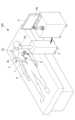
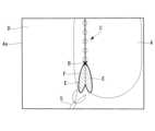
図1に示されるように、手術システム100は、患者Pの体内の処置対象Aを撮影する撮像装置としての内視鏡1と、内視鏡1を移動させる移動装置2と、内視鏡1および移動装置2を制御する制御装置3と、内視鏡1によって撮影された処置対象Aを表示する表示装置4とを備える。なお、撮像装置は、内視鏡1に限らず、患者Pの体内の処置対象Aを撮影する任意の装置であってもよい。[Configuration of surgical system 100]
The
1, the
内視鏡1は硬性鏡であり、内視鏡1の先端部には、臓器または組織等の処置対象Aを撮影するためのレンズおよび撮像素子等の素子が設けられている。内視鏡1は、移動装置2の内部を通る信号線によって制御装置3と接続され、内視鏡1を制御するための制御信号を制御装置3から受信し、内視鏡画像のデータを制御装置3に送信する。
移動装置2は、少なくとも1つの屈曲関節2aを有する電動駆動のロボットアームであり、ロボットアーム2の先端部に内視鏡1の基端部が接続されている。 The
The moving
表示装置4は、液晶ディスプレイ等の公知の表示装置であり、画面4aを有する。表示装置4は、制御装置3と接続され、制御装置3から入力された処置対象Aの内視鏡画像を画面4aに表示する。表示装置4は、ヘッドマウントディスプレイまたはプロジェクタであってもよい。
ロボットアーム2の関節2aの屈曲動作によって内視鏡1が移動し、それにより、内視鏡1の視野、すなわち画面4aに表示される処置対象Aの表示範囲が移動する。ロボットアーム2の動作は制御装置3によって制御される。 The
The
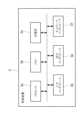
図2に示されるように、制御装置3は、中央演算処理装置のような少なくとも1つのプロセッサ3aと、メモリ3bと、記憶部3cと、入力インタフェース3dと、出力インタフェース3eと、ネットワークインタフェース3fとを備える。
内視鏡1から送信された内視鏡画像は、入力インタフェース3dを経由して制御装置3に逐次入力され、出力インタフェース3eを経由して表示装置4に逐次出力される。これにより、画面4aに、内視鏡1によって撮影された処置対象Aの内視鏡画像が表示される。 As shown in FIG. 2, the
The endoscopic images transmitted from the
記憶部3cは、ROM(read-only memory)またはハードディスク等の不揮発性の記録媒体であり、プロセッサ3aに処理を実行させるために必要なプログラムおよびデータを記憶している。制御装置3の後述の機能は、プログラムがメモリ3bに読み込まれプロセッサ3aによって実行されることによって、実現される。制御装置3の一部の機能は、専用の論理回路等によって実現されてもよい。The
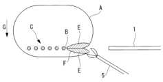
図3Aおよび図3Bに示されるように、肝切除術のような処置対象Aを切離する手術において、重力Gの影響および処置対象Aの柔らかさの影響によって、切離を進めるにつれて処置対象Aの少なくとも一部が変形したり移動したりする。その結果、図4Aおよび図4Bに示されるように、画面4a内の処置対象Aの位置、向きおよび表示範囲の広さが次第に変化することがある。図3Aから図3Cは、処置対象Aである肝臓の実質を離断する肝切除を示している。図3Aから図3Cにおいて、重力Gは、紙面の上から下へ向かう方向である。As shown in Figures 3A and 3B, in a surgery to cut a treatment target A, such as a hepatectomy, gravity G and the softness of the treatment target A cause at least a part of the treatment target A to deform or move as the cutting proceeds. As a result, as shown in Figures 4A and 4B, the position, orientation, and display range of the treatment target A on the
制御装置3は、第1特徴量、第2特徴量および第3特徴量を算出する。第1特徴量は、画面4a内の処置対象Aの構図を表す量である。第2特徴量は、画面4a内での処置対象Aの向きを表す量である。第3特徴量は、画面4aに表示されている処置対象Aの表示範囲の広さ、すなわち内視鏡1の視野の広さを表す量である。
具体的には、制御装置3は、第1特徴量として、画面4a内での切離端部Bの位置を算出する。切離端部Bは、処置具5によって形成された切離線の先端部である。切離端部Bの位置は、画面4aに固定された画面座標系Σsでの切離端部Bの座標である。また、制御装置3は、第2特徴量として、画面4a内のマーキングCの向き(画面4aに沿う平面内でのマーキングCの回転角度)を算出する。マーキングCは、処置対象Aの切離前に処置対象Aの外面に付された切離予定線であり、例えば点線または実線である。マーキングCは、例えば、処置対象Aの外面を電気メスで焼灼することによって付される。そして、制御装置3は、第3特徴量として、内視鏡1の先端と切離端部Bとの間の距離を算出する。
各特徴量の具体的な算出方法については、後で詳述する。 The
Specifically, the
A specific method for calculating each feature amount will be described in detail later.
制御装置3は、逐次入力される内視鏡画像の中から1つの内視鏡画像を取り込み、取り込んだ内視鏡画像に基づいて前述した第1特徴量、第2特徴量および第3特徴量を算出する。次に、制御装置3は、算出された第1、第2および第3特徴量に基づいてロボットアーム2を制御することによって、各特徴量が所定の基準と同等となるように内視鏡1の視野を移動させる。これにより、画面4a上に所定の基準に従って処置対象Aが表示され続ける。
また、制御装置3は、特徴量の算出および内視鏡1の視野の移動に先立ち、内視鏡画像Dに基づいて所定の基準を設定する。所定の基準の設定方法については、後で詳述する。 The
Furthermore, prior to calculating the feature amount and moving the field of view of the
[手術システム100の制御方法]
次に、制御装置3によって実行される手術システム100の制御方法について説明する。
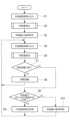
図5Aに示されるように、手術システム100の制御方法は、3つの特徴量の各々の基準を設定する基準設定ステップS1~S3と、内視鏡画像Dに基づいて3つの特徴量を算出する特徴量算出ステップS4,S5と、移動装置2の制御によって内視鏡1の視野を調整する視野調整ステップS6とを含む。[Control method of surgical system 100]
Next, a control method for the
As shown in FIG. 5A, the control method of the
基準設定ステップは、内視鏡画像Dを取り込むステップS1と、3つの特徴量を算出するステップS2と、各特徴量の基準を設定するステップS3とを含む。
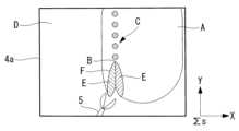
ステップS1において、制御装置3は、逐次入力される内視鏡画像Dの中から1つの内視鏡画像Dを取り込む。このときに取り込まれる内視鏡画像Dは、図4Aに示されるように、処置対象Aの変形による切離端部BおよびマーキングCの移動が生じる前の画像である。画像の取り込みは、例えば、作業者による制御装置3への入力に応答して実行される。 The reference setting step includes step S1 of capturing an endoscopic image D, step S2 of calculating three feature amounts, and step S3 of setting a reference for each feature amount.
In step S1, the
次に、ステップS2において、取り込まれた内視鏡画像Dに基づき、3つの特徴量の各々が算出される。具体的には、ステップS2は、図5Bに示されるように、内視鏡画像D内のマーキングCおよび切離面EのエッジFを認識するステップS21と、第1特徴量を算出するステップS22と、第2特徴量を算出するステップS23と、第3特徴量を算出するステップS24~S26とを含む。Next, in step S2, each of the three feature amounts is calculated based on the captured endoscopic image D. Specifically, as shown in Fig. 5B, step S2 includes step S21 of recognizing the marking C and the edge F of the cutting surface E in the endoscopic image D, step S22 of calculating the first feature amount, step S23 of calculating the second feature amount, and steps S24 to S26 of calculating the third feature amount.
ステップS21において、図6に示されるように、制御装置3は、内視鏡画像Dに画像処理を施すことによって、マーキングCと、切離面EのエッジFとを認識する。マーキングCおよび切離面Eは、処置対象Aの外面および周辺組織とは異なる色を有するので、制御装置3は、色に基づいてマーキングCおよび切離面Eを認識することができる。このとき、画像処理によって両側の切離面Eを相互に区別して認識することは難しく、両側の切離面Eは1つの面として認識される。したがって、エッジFは、単一の線として認識される。In step S21, as shown in Fig. 6, the
次に、ステップS22において、制御装置3は、画面4a内でのマーキングCとエッジFとの交点の位置を切離端部Bの位置として算出する。切離端部Bの位置は、画面座標系Σsでの座標として表わされる。
図6に示されるようにマーキングCが点線である場合、点同士を接続する実線を生成し、実線とエッジFとの交点の位置を算出してもよい。
また、閉環状のエッジFまたは複数本のエッジFが認識された場合、複数の交点の位置が算出され得る。この場合、マーキングCに最も近い交点の位置を切離端部Bの位置として採用してもよい。 Next, in step S22, the
When the marking C is a dotted line as shown in FIG. 6, a solid line connecting the dots may be generated, and the position of the intersection between the solid line and the edge F may be calculated.
Furthermore, when a closed loop edge F or a plurality of edges F are recognized, the positions of a plurality of intersections can be calculated. In this case, the position of the intersection closest to the marking C may be adopted as the position of the cut-off end B.
次に、ステップS23において、制御装置3は、画面4a内でのマーキングC上の任意の相異なる2点の位置を検出する。2点の位置は、画面座標系Σsでの座標として表される。次に、制御装置3は、2点を結ぶベクトルを画面4a内でのマーキングCの向きとして算出する。
ステップS22およびステップS23の順番は任意であり、ステップS23の後にステップS22が実行されてもよい。 Next, in step S23, the
The order of steps S22 and S23 is arbitrary, and step S22 may be performed after step S23.
次に、ステップS24において、制御装置3は、内視鏡1を保持するロボットのベース座標系Σrでの内視鏡1の先端の位置を検出する。ベース座標系Σrは、ロボットアーム2の非可動部分(例えば、ロボットアーム2の基端部)に対して固定された座標系である。例えば、制御装置3は、ロボットアーム2の各関節2aに設けられた角度センサによって各関節2aの回転角度を取得し、回転角度に基づいて内視鏡1の先端の位置を検出する。内視鏡1の先端の位置は、ロボットのベース座標系Σrでの座標として表される。Next, in step S24, the
次に、ステップS25において、制御装置3は、ステップS22において算出された切離端部Bの位置を、ロボットのベース座標系Σrでの位置に変換する。また、制御装置3は、ステップS23において算出されたマーキングCの向きを、ロボットのベース座標系Σrでの向きに変換する。
次に、ステップS26において、制御装置3は、ステップS24およびS25において得られた内視鏡1の先端の位置と切離端部Bの位置との間の距離を算出し、算出された距離を記憶部3cに記憶させる。また、制御装置3は、ステップS25で変換された切離端部Bの位置とマーキングCの向きを記憶部3cに記憶させる。 Next, in step S25, the
Next, in step S26, the
次に、ステップS3において、制御装置3は、記憶部3cに記憶された切離端部Bの位置を、第1特徴量の基準である所定の基準位置に設定する。また、制御装置3は、記憶部3cに記憶されたマーキングCの向きを、第2特徴量の基準である所定の基準向きに設定する。また、制御装置3は、記憶部3cに記憶された距離を、第3特徴量の基準である所定の基準距離に設定する。Next, in step S3, the
次に、特徴量算出ステップが行われる。特徴量算出ステップは、内視鏡画像Dを再度取り込むステップS4と、取り込まれた内視鏡画像Dに基づいて3つの特徴量を再度算出するステップS5と、を含む。
ステップS4において、制御装置3は、内視鏡画像Dを再び取り込む。このときに取り込まれる内視鏡画像Dは、図4Bに示されるように、ステップS1において取り込まれた内視鏡画像Dから時間が経過した内視鏡画像であり、切離が進んだときの内視鏡画像である。
次に、ステップS5において、制御装置3は、再び取り込んだ内視鏡画像Dに基づいてステップS21~S26と同じ処理を行うことによって、3つの特徴量を算出する。 Next, a feature amount calculation step is performed, which includes step S4 of capturing the endoscopic image D again, and step S5 of calculating the three feature amounts again based on the captured endoscopic image D.
In step S4, the
Next, in step S5, the
次に、視野調整ステップS6において、制御装置3は、ステップS5において算出された3つの特徴量の各々を基準と比較し、基準からの各特徴量の変化量を算出する。次に、制御装置3は、各特徴量の変化量がゼロとなり各特徴量が基準と同等となる内視鏡1の目標位置および目標姿勢を算出する。すなわち、目標位置および目標姿勢は、切離端部Bが画面4a内の基準位置に配置され、マーキングCが画面4a内で基準向きに配置され、かつ、切離端部Bから内視鏡1の先端までの距離が基準距離と等しくなる、内視鏡1の位置および姿勢である。Next, in a field of view adjustment step S6, the
次に、制御装置3は、内視鏡1を目標位置および目標姿勢に移動させるための内視鏡1の移動量および移動方向を算出し、算出された移動量および移動方向を達成するためのロボットアーム2の動作量(具体的には各関節2aの回転量)を算出する。続いて、制御装置3は、算出された動作量だけロボットアーム2を動作させるための制御信号を生成し、制御信号をロボットアーム2に送信する。Next, the
これにより、図3Cに示されるように、ロボットアーム2は制御信号に応答して動作する。それによって、3つの特徴量の変化が相殺される目標位置および目標姿勢に腹腔内で内視鏡1が移動し、内視鏡1の視野が移動する。その結果、図4Cに示されるように、画面4aに表示される処置対象Aの表示範囲が移動および回転し、切離端部Bが所定の基準位置に配置され、マーキングCが所定の基準向きに配置される。また、内視鏡1の先端から切離端部Bまでの距離が所定の基準距離に調整され、画面4aに表示される処置対象Aの表示範囲の広さが所定の広さに維持される。As a result, as shown in Figure 3C, the
このように、本実施形態によれば、切離の進行に伴って肝臓等の処置対象Aが変形し特徴量が変化したとき、特徴量の変化が相殺される位置および方向に内視鏡1が自動的に移動する。つまり、切離端部BおよびマーキングCの移動に追従して内視鏡1の視野が自動的に移動する。これにより、マーキングCに沿って処置対象Aを切離している間、切離端部Bの位置、マーキングCの方向および視野の広さが、それぞれの基準に維持される。例えば、切離端部Bの位置は画面4aの中央に表示され続け、マーキングCは画面4aの縦方向に表示され続ける。
処置対象Aの切離中、術者は、画面4aに表示される内視鏡画像Dの処置対象Aに基づいて処置具5の位置および移動方向を制御する。本実施形態によれば、切離中の処置対象Aの変形に関わらず、処置対象Aを術者にとって処置し易い状態で画面4aに表示し続けることができる。 Thus, according to this embodiment, when the treatment target A such as the liver is deformed and the feature amount changes as the resection progresses, the
During the dissection of the treatment target A, the surgeon controls the position and the moving direction of the
内視鏡1が移動できる範囲が制限されている場合、3つの特徴量の各々が基準と同等となる目標位置および目標姿勢に内視鏡1を移動させることができないことがある。例えば、内視鏡1と周辺物体(例えば、周辺組織または他の器具)との干渉を防止する機能が手術システム100に搭載されている場合、内視鏡1と周辺物体との干渉が予測される位置には内視鏡1を移動させることができない。このような場合、制御装置3は、内視鏡画像Dの処理によって3つの特徴量の各々の基準からの変化量がゼロになる画像を作成し、作成された画像を表示装置4に出力して画面4aに表示させてもよい。これにより、内視鏡1を移動させたときと同様に、画面4aに表示される処置対象Aの表示範囲を移動および回転させることができる。If the range in which the
具体的には、図7に示されるように、ステップS5の後にステップS7~S10が追加されてもよい。
制御装置3は、ステップS7において、目標位置および目標姿勢に内視鏡1を移動させることができるか否かを判定する。目標位置および目標姿勢に内視鏡1を移動することができないと判断した場合(ステップS7のNO)、制御装置3は、ステップS8において、特徴量の変化がゼロの内視鏡画像Dを画像処理によって作成できるか否かを判定する。特徴量の変化がゼロになる内視鏡画像Dを画像処理によって作成できる場合(ステップS8のYES)、制御装置3は、ステップS9において、画像処理を行う。具体的には、制御装置3は、ステップS4において取り込まれた内視鏡画像Dにトリミング、拡大縮小および回転の処理を施すことによって、特徴量の変化量がゼロになる画像を作成する。
特徴量の変化がゼロになる画像を画像処理によって作成することができない場合(ステップS8のNO)、制御装置3は、ステップS10において、特徴量の基準を更新してもよい。例えば、制御装置3は、ステップS5において算出された特徴量を新たな基準に設定してもよい。 Specifically, as shown in FIG. 7, steps S7 to S10 may be added after step S5.
In step S7, the
If an image in which the change in the feature amount is zero cannot be created by image processing (NO in step S8), the
上記実施形態において、ステップS4~S6の前に内視鏡画像Dに基づいて特徴量を事前に算出し、事前に算出された特徴量を基準に設定することとしたが、これに代えて、図8に示されるように、基準が予め設定されていてもよい。図9は、予め設定された第1特徴量および第2特徴量の基準の例を示している。
第1特徴量の基準である基準位置は、画面4a内の所定の一点または所定の一部分に設定される(ステップS11)。基準位置は、画面4aの中心点または中心領域であってもよい。図9に示されるように、中心領域は、中心点から横方向に画面4aの横寸法の±15%の範囲内、かつ、縦方向に、画面4aの縦寸法の±15%の範囲内であることが好ましい。中心領域は、矩形に限定されず、例えば、画面4aの中心点を中心とする円形または楕円形の領域であってもよい。 In the above embodiment, the feature amounts are calculated in advance based on the endoscopic image D before steps S4 to S6, and the previously calculated feature amounts are set as the references, but instead, the references may be set in advance as shown in Fig. 8. Fig. 9 shows an example of preset references for the first feature amount and the second feature amount.
The reference position, which is the reference of the first feature amount, is set at a predetermined point or a predetermined part in the
第2特徴量の基準である基準向きは、画面4a内のマーキングCの両端部の内、切離端部Bから遠い方の端部が、画面4aの中心点から横方向に±15%の範囲内(I-Iの範囲内)に配置される方向に設定される(ステップS12)。これにより、マーキングCは、画面4aの縦方向に平行または略平行な方向に維持される。マーキングCが画面4aの横方向に平行または略平行な方向に維持されるようにするために、基準向きは、マーキングCの遠い方の端部が、画面4aの中心点から縦方向に±15%の範囲内(II-IIの範囲内)に配置される方向に設定されてもよい。
第3特徴量の基準である基準距離は、上述したステップS21,S22,S24~S26,S3と同じ方法で設定される(ステップS13)。 The reference orientation, which is the reference for the second characteristic amount, is set to a direction in which the end farther from the cut-off end B, out of both ends of the marking C in the
The reference distance, which is the reference for the third feature amount, is set in the same manner as in steps S21, S22, S24 to S26, and S3 described above (step S13).
上記実施形態において、マーキングCと切離面EのエッジFとの交点を切離端部Bの位置として算出することとしたが、切離端部Bの位置の算出方法はこれに限定されるものではなく、他の方法で算出してもよい。
図10Aおよび図10Bは、切離端部Bの算出方法の他の例を説明している。 In the above embodiment, the intersection point between the marking C and the edge F of the cutting surface E is calculated as the position of the cutting end B, but the method of calculating the position of the cutting end B is not limited to this and may be calculated using other methods.
10A and 10B illustrate another example of a method for calculating the cut-off end B. FIG.
図10Aにおいて、制御装置3は、切離面Eの重心Hの位置を算出し、画面4a内でのマーキングCの両端部の内、重心Hに近い方の端部の位置を切離端部Bの位置として算出する。
図10Bにおいて、制御装置3は、一側の切離面EのエッジFと他側の切離面EのエッジFとの交点の位置を切離端部Bの位置として算出する。もしくは、制御装置3は、各側の切離面EのエッジFを直線近似し、2本の直線の交点の位置を切離端部Bの位置として算出してもよい。
切離面Eの上側のエッジFは上に凸の曲線であり、エッジFの頂点に切離端部Bが位置する。したがって、エッジFの頂点を検出することができる他の方法を用いてもよい。例えば、制御装置3は、エッジFを表す曲線の極大点を切離端部Bの位置として算出してもよい。 In FIG. 10A, the
10B, the
The edge F on the upper side of the cut-off surface E is an upwardly convex curve, and the cut-off end B is located at the apex of the edge F. Therefore, other methods capable of detecting the apex of the edge F may be used. For example, the
上記実施形態において、マーキングCが処置対象に直接付される例を説明したが、マーキングCは、内視鏡画像Dに重畳して表示される仮想のマーキングであってもよい。すなわち、マーキングCは、内視鏡画像Dを画像処理することによって画面4aに表示されるマーキングであってもよい。マーキングCは、処置対象の情報に基づいて公知の技術によって形成され、内視鏡画像Dに重畳して画面4aに表示される。In the above embodiment, an example has been described in which the marking C is directly applied to the treatment target, but the marking C may be a virtual marking that is displayed superimposed on the endoscopic image D. In other words, the marking C may be a marking that is displayed on the
上記実施形態において、処置対象Aが肝臓であり、肝実質を離断する腹腔鏡下手術を例に説明したが、手術システム100が適用される処置対象Aおよび手術はこれに限定されるものではなく、他の処置対象および手術にも手術システム100を適用することができる。
例えば、S状結腸切除術において、S状結腸から筋膜を剥離するとき、腹腔内で剥離線が移動し得る。この場合、剥離の進捗に応じて剥離線に内視鏡1の視野を追従させ、剥離線が処置し易い位置、方向および距離に配置されるように内視鏡1を自律移動させることができる。
また、手術システム100は、腹腔鏡以外の種類の内視鏡を備え、腹腔鏡下手術以外の内視鏡下手術に適用されてもよい。 In the above embodiment, the treatment target A is the liver, and laparoscopic surgery in which the liver parenchyma is transected is described as an example. However, the treatment target A and the surgery to which the
For example, in a sigmoid resection, when the fascia is dissected from the sigmoid colon, the dissection line may move within the abdominal cavity. In this case, the field of view of the
Furthermore, the
上記実施形態において、画面4aに表示される処置対象Aの表示範囲を内視鏡1の移動によって移動および回転させることとしたが、これに代えて、画像処理のみで表示範囲を移動および回転させてもよい。
例えば、内視鏡1が広範囲の内視鏡画像Dを取得し、内視鏡画像Dの一部分が画面4aに表示される。この場合、内視鏡画像Dの内、画面4aに表示される部分を移動および回転させることによって、内視鏡1を移動させた場合と同じ作用効果を得ることができる。 In the above embodiment, the display range of the treatment object A displayed on the
For example, the
100 手術システム
1 内視鏡(撮像装置)
2 移動装置、ロボットアーム
3 制御装置
4 表示装置
4a 画面
5 処置具
A 処置対象
B 切離端部
C マーキング
D 内視鏡画像
G 重力100
2 Moving device,
Claims (23)
Translated fromJapanese該撮像装置によって撮影された前記処置対象を表示する画面を有する表示装置と、
前記画面に表示される前記処置対象の表示範囲を制御する制御装置と、を備え、
該制御装置は、
前記撮像装置によって取得された前記処置対象の画像に基づいて前記処置対象の切離端部の位置を算出し、
前記切離端部が前記画面内の所定の基準位置に配置される位置に前記処置対象の表示範囲を移動させ、
前記画面内での前記処置対象に付されたマーキングの向きを算出し、
該マーキングが前記画面内で所定の基準向きに配置される向きに前記処置対象の表示範囲を回転させる、手術システム。 An imaging device for photographing a treatment target;
a display device having a screen for displaying the treatment target photographed by the imaging device;
a control device for controlling a display range of the treatment target displayed on the screen,
The control device includes:
Calculating a position of a cut end of the treatment target based on an image of the treatment target acquired by the imaging device;
moving a display range of the treatment target to a position where the resected end portion is placed at a predetermined reference position on the screen;
Calculating the orientation of the marking on the treatment target within the screen;
A surgical systemthat rotates the display range of the treatment object in an orientation in which the marking is positioned in a predetermined reference orientation within the screen .
前記制御装置は、
算出された前記切離端部の位置の前記所定の基準位置からの変化量を算出し、
前記移動装置を制御することによって前記変化量がゼロになる位置に前記撮像装置を移動させる、請求項1に記載の手術システム。 a moving device that moves the imaging device,
The control device includes:
Calculating the amount of change in the calculated position of the cut-off end from the predetermined reference position;
The surgical system according to claim 1 , wherein the imaging device is moved to a position where the amount of change becomes zero by controlling the moving device.
該撮像装置によって撮影された前記処置対象を表示する画面を有する表示装置と、
前記画面に表示される前記処置対象の表示範囲を制御する制御装置と、を備え、
該制御装置は、
前記撮像装置によって取得された前記処置対象の画像に基づいて前記処置対象の切離端部の位置を算出し、
前記画像の処理によって、前記切離端部が前記画面内の所定の基準位置に配置される位置に前記処置対象の表示範囲を移動させる、手術システム。An imaging device for photographing a treatment target;
a display device having a screen for displaying the treatment target photographed by the imaging device;
a control device for controlling a display range of the treatment target displayed on the screen,
The control device includes:
Calculating a position of a cut end of the treatment target based on an image of the treatment target acquired by the imaging device;
Asurgical system that processesthe image to move the display range of the treatment objectto a position where the resected end is placed at a predetermined reference position within the screen .
前記撮像装置によって取得された前記処置対象の画像に基づいて前記処置対象の切離端部の位置を算出し、
前記切離端部が前記画面内の所定の基準位置に配置される位置に前記処置対象の表示範囲を移動させ、
前記画面内での前記処置対象に付されたマーキングの向きを算出し、
該マーキングが前記画面内で所定の基準向きに配置される向きに前記処置対象の表示範囲を回転させる、手術システムの制御方法。 A control method executed by a control device of a surgical system, the surgical system comprising: an imaging device that captures an image of a treatment target; and a display device having a screen that displays the treatment target captured by the imaging device;
Calculating a position of a cut end of the treatment target based on an image of the treatment target acquired by the imaging device;
moving a display range of the treatment target to a position where the resected end portion is placed at a predetermined reference position on the screen;
Calculating the orientation of the marking on the treatment target within the screen;
A control method for a surgical system,which rotates the display range of the treatment object to an orientation in which the marking is placed in a predetermined reference orientation on the screen .
前記処置対象の表示範囲を移動させることは、
前記切離端部が前記画面内の所定の基準位置に配置される前記撮像装置の目標位置を算出し、
前記移動装置を制御することによって前記目標位置に前記撮像装置を移動させることを含む、請求項12に記載の手術システムの制御方法。 the surgical system includes a moving device that moves the imaging device;
The moving of the display range of the treatment target includes:
calculating a target position of the imaging device where the cut end portion is disposed at a predetermined reference position within the screen;
The method for controlling a surgical system according to claim12 , further comprising controlling the moving device to move the imaging device to the target position.
前記撮像装置によって取得された前記処置対象の画像に基づいて前記処置対象の切離端部の位置を算出し、
前記画像の処理によって、前記切離端部が前記画面内の所定の基準位置に配置される位置に前記処置対象の表示範囲を移動させる、手術システムの制御方法。A control method executed by a control device of a surgical system, the surgical system comprising: an imaging device that captures an image of a treatment target; and a display device having a screen that displays the treatment target captured by the imaging device;
Calculating a position of a cut end of the treatment target based on an image of the treatment target acquired by the imaging device;
A method for controlling asurgical system, comprising: processing the image to move a display range of the treatment targetto a position where the resected end is located at a predetermined reference position within the screen .
Applications Claiming Priority (1)
| Application Number | Priority Date | Filing Date | Title |
|---|---|---|---|
| PCT/JP2021/006642WO2022176199A1 (en) | 2021-02-22 | 2021-02-22 | Surgical system and method for controlling surgical system |
Publications (3)
| Publication Number | Publication Date |
|---|---|
| JPWO2022176199A1 JPWO2022176199A1 (en) | 2022-08-25 |
| JPWO2022176199A5 JPWO2022176199A5 (en) | 2023-08-31 |
| JP7549731B2true JP7549731B2 (en) | 2024-09-11 |
Family
ID=82930529
Family Applications (1)
| Application Number | Title | Priority Date | Filing Date |
|---|---|---|---|
| JP2023500490AActiveJP7549731B2 (en) | 2021-02-22 | 2021-02-22 | Surgery system and method for controlling the surgery system |
Country Status (4)
| Country | Link |
|---|---|
| US (1) | US12383126B2 (en) |
| JP (1) | JP7549731B2 (en) |
| CN (1) | CN116761570A (en) |
| WO (1) | WO2022176199A1 (en) |
Citations (4)
| Publication number | Priority date | Publication date | Assignee | Title |
|---|---|---|---|---|
| US20080114334A1 (en) | 2006-11-10 | 2008-05-15 | Voegele James W | Adhesive Marker |
| JP2015154803A (en) | 2014-02-20 | 2015-08-27 | オリンパス株式会社 | endoscope system |
| WO2018159328A1 (en) | 2017-02-28 | 2018-09-07 | ソニー株式会社 | Medical arm system, control device, and control method |
| WO2018159155A1 (en) | 2017-02-28 | 2018-09-07 | ソニー株式会社 | Medical observation system, control device, and control method |
Family Cites Families (26)
| Publication number | Priority date | Publication date | Assignee | Title |
|---|---|---|---|---|
| EP1491150A1 (en)* | 2003-06-27 | 2004-12-29 | Universite Libre De Bruxelles | Method of acquiring informations in order to insert a locking screw in a hole of a metallic object |
| US9636188B2 (en)* | 2006-03-24 | 2017-05-02 | Stryker Corporation | System and method for 3-D tracking of surgical instrument in relation to patient body |
| GB2464092A (en)* | 2008-09-25 | 2010-04-07 | Prosurgics Ltd | Surgical mechanism control system |
| US20110218550A1 (en)* | 2010-03-08 | 2011-09-08 | Tyco Healthcare Group Lp | System and method for determining and adjusting positioning and orientation of a surgical device |
| JP2016513540A (en)* | 2013-03-15 | 2016-05-16 | ザ クリーブランド クリニック ファウンデーションThe Cleveland ClinicFoundation | System that facilitates positioning and guidance during surgery |
| WO2014181222A1 (en) | 2013-05-09 | 2014-11-13 | Koninklijke Philips N.V. | Robotic control of an endoscope from anatomical features |
| WO2015179446A1 (en)* | 2014-05-20 | 2015-11-26 | BROWND, Samuel, R. | Systems and methods for mediated-reality surgical visualization |
| US20220031422A1 (en)* | 2015-11-03 | 2022-02-03 | Synaptive Medical Inc. | System and methods using a videoscope with independent-zoom for enabling shared-mode focusing |
| JP6876065B2 (en)* | 2015-12-14 | 2021-05-26 | ニューヴェイジヴ,インコーポレイテッド | 3D visualization during surgery with reduced radiation |
| CN111329553B (en)* | 2016-03-12 | 2021-05-04 | P·K·朗 | Devices and methods for surgery |
| US10463435B2 (en)* | 2016-06-30 | 2019-11-05 | OrthoGrid Systems, Inc | Surgical instrument positioning system, apparatus and method of use as a noninvasive anatomical reference |
| US20180049622A1 (en)* | 2016-08-16 | 2018-02-22 | Insight Medical Systems, Inc. | Systems and methods for sensory augmentation in medical procedures |
| US10440346B2 (en)* | 2016-09-30 | 2019-10-08 | Medi Plus Inc. | Medical video display system |
| US10529088B2 (en)* | 2016-12-02 | 2020-01-07 | Gabriel Fine | Automatically determining orientation and position of medically invasive devices via image processing |
| JP6360644B1 (en)* | 2016-12-19 | 2018-07-18 | オリンパス株式会社 | Endoscope insertion shape observation device |
| WO2018132804A1 (en)* | 2017-01-16 | 2018-07-19 | Lang Philipp K | Optical guidance for surgical, medical, and dental procedures |
| AU2018346790B2 (en)* | 2017-10-05 | 2024-09-26 | Mobius Imaging, Llc | Methods and systems for performing computer assisted surgery |
| WO2019140533A1 (en)* | 2018-01-22 | 2019-07-25 | Claronav Inc. | Robotic surgical tool |
| WO2019163906A1 (en) | 2018-02-21 | 2019-08-29 | オリンパス株式会社 | Medical system and operation method of medical system |
| JP6632652B2 (en)* | 2018-03-29 | 2020-01-22 | 株式会社吉田製作所 | Image processing apparatus and image processing program |
| AU2019269713A1 (en)* | 2018-05-18 | 2020-11-26 | Smith & Nephew Asia Pacific Pte Limited | System and method for tracking resection planes |
| EP4051080B1 (en)* | 2019-12-19 | 2025-02-19 | Sony Group Corporation | Method, apparatus and system for controlling an image capture device during surgery |
| US20230017738A1 (en)* | 2019-12-19 | 2023-01-19 | Sony Group Corporation | Method, apparatus and system for controlling an image capture device during surgery |
| JP7729839B2 (en)* | 2020-05-11 | 2025-08-26 | ヴィカリアス・サージカル・インコーポレイテッド | Systems and methods for in vivo reversal of the orientation and field of view of selected components of a miniaturized surgical robotic unit - Patents.com |
| US11786106B2 (en)* | 2020-05-26 | 2023-10-17 | Canon U.S.A., Inc. | Robotic endoscope probe having orientation reference markers |
| EP4105887A1 (en)* | 2021-06-15 | 2022-12-21 | Stryker European Operations Limited | Technique of generating surgical information from intra-operatively and pre-operatively acquired image data |
- 2021
- 2021-02-22JPJP2023500490Apatent/JP7549731B2/enactiveActive
- 2021-02-22WOPCT/JP2021/006642patent/WO2022176199A1/ennot_activeCeased
- 2021-02-22CNCN202180091596.9Apatent/CN116761570A/enactivePending
- 2023
- 2023-06-14USUS18/209,854patent/US12383126B2/enactiveActive
Patent Citations (4)
| Publication number | Priority date | Publication date | Assignee | Title |
|---|---|---|---|---|
| US20080114334A1 (en) | 2006-11-10 | 2008-05-15 | Voegele James W | Adhesive Marker |
| JP2015154803A (en) | 2014-02-20 | 2015-08-27 | オリンパス株式会社 | endoscope system |
| WO2018159328A1 (en) | 2017-02-28 | 2018-09-07 | ソニー株式会社 | Medical arm system, control device, and control method |
| WO2018159155A1 (en) | 2017-02-28 | 2018-09-07 | ソニー株式会社 | Medical observation system, control device, and control method |
Also Published As
| Publication number | Publication date |
|---|---|
| US12383126B2 (en) | 2025-08-12 |
| US20230320793A1 (en) | 2023-10-12 |
| CN116761570A (en) | 2023-09-15 |
| WO2022176199A1 (en) | 2022-08-25 |
| JPWO2022176199A1 (en) | 2022-08-25 |
Similar Documents
| Publication | Publication Date | Title |
|---|---|---|
| EP4041048B1 (en) | Systems and methods for changing the direction of view during video guided clinical procedures using real-time image processing | |
| KR101038417B1 (en) | Surgical Robot System and Its Control Method | |
| JP7522840B2 (en) | Control device | |
| CA2958163C (en) | Digitally enhanced surgical instruments | |
| JP7160033B2 (en) | Input control device, input control method, and surgical system | |
| JP5814938B2 (en) | Calibration-free visual servo using real-time speed optimization | |
| JP2020062521A (en) | Graphical user interface for robot surgery system | |
| JP6257371B2 (en) | Endoscope system and method for operating endoscope system | |
| CN116981411A (en) | Laparoscopic surgical robotic system with internal articulation degrees of freedom | |
| JP2013516264A5 (en) | ||
| US12263043B2 (en) | Method of graphically tagging and recalling identified structures under visualization for robotic surgery | |
| KR100962472B1 (en) | Surgical robot system and control method thereof | |
| US11241144B2 (en) | Medical system and operation method of medical system | |
| JP7549731B2 (en) | Surgery system and method for controlling the surgery system | |
| JP2021000258A (en) | Medical observation system, medical observation method, and information processing device | |
| WO2023038127A1 (en) | Inference device, information processing method, and computer program | |
| WO2023195326A1 (en) | Endoscope system, procedure supporting method, and procedure supporting program | |
| US20250302273A1 (en) | Medical system, control device, control method, and control program | |
| JP2025151384A (en) | Medical system, control device, control method, and control program | |
| Hayashibe et al. | Real-time 3D deformation imaging of abdominal organs in laparoscopy | |
| WO2025019594A1 (en) | Systems and methods for implementing a zoom feature associated with an imaging device in an imaging space | |
| EP4568609A1 (en) | Method for controlling a slave device, controlled by a master device in a robotic system for medical or surgical teleoperation, taking into account limits of a field of view, and related robotic system |
Legal Events
| Date | Code | Title | Description |
|---|---|---|---|
| A521 | Request for written amendment filed | Free format text:JAPANESE INTERMEDIATE CODE: A523 Effective date:20230613 | |
| A621 | Written request for application examination | Free format text:JAPANESE INTERMEDIATE CODE: A621 Effective date:20230613 | |
| TRDD | Decision of grant or rejection written | ||
| A01 | Written decision to grant a patent or to grant a registration (utility model) | Free format text:JAPANESE INTERMEDIATE CODE: A01 Effective date:20240806 | |
| A61 | First payment of annual fees (during grant procedure) | Free format text:JAPANESE INTERMEDIATE CODE: A61 Effective date:20240830 | |
| R150 | Certificate of patent or registration of utility model | Ref document number:7549731 Country of ref document:JP Free format text:JAPANESE INTERMEDIATE CODE: R150 |