JP7549595B2 - Postpartum uterine bleeding device - Google Patents
Postpartum uterine bleeding deviceDownload PDFInfo
- Publication number
- JP7549595B2 JP7549595B2JP2021555152AJP2021555152AJP7549595B2JP 7549595 B2JP7549595 B2JP 7549595B2JP 2021555152 AJP2021555152 AJP 2021555152AJP 2021555152 AJP2021555152 AJP 2021555152AJP 7549595 B2JP7549595 B2JP 7549595B2
- Authority
- JP
- Japan
- Prior art keywords
- uterus
- holes
- instrument
- vacuum
- insertable
- Prior art date
- Legal status (The legal status is an assumption and is not a legal conclusion. Google has not performed a legal analysis and makes no representation as to the accuracy of the status listed.)
- Active
Links
Images


Classifications
- A—HUMAN NECESSITIES
- A61—MEDICAL OR VETERINARY SCIENCE; HYGIENE
- A61B—DIAGNOSIS; SURGERY; IDENTIFICATION
- A61B17/00—Surgical instruments, devices or methods
- A61B17/42—Gynaecological or obstetrical instruments or methods
- A—HUMAN NECESSITIES
- A61—MEDICAL OR VETERINARY SCIENCE; HYGIENE
- A61B—DIAGNOSIS; SURGERY; IDENTIFICATION
- A61B17/00—Surgical instruments, devices or methods
- A61B17/12—Surgical instruments, devices or methods for ligaturing or otherwise compressing tubular parts of the body, e.g. blood vessels or umbilical cord
- A61B17/12022—Occluding by internal devices, e.g. balloons or releasable wires
- A61B17/12027—Type of occlusion
- A61B17/1204—Type of occlusion temporary occlusion
- A—HUMAN NECESSITIES
- A61—MEDICAL OR VETERINARY SCIENCE; HYGIENE
- A61B—DIAGNOSIS; SURGERY; IDENTIFICATION
- A61B17/00—Surgical instruments, devices or methods
- A61B17/12—Surgical instruments, devices or methods for ligaturing or otherwise compressing tubular parts of the body, e.g. blood vessels or umbilical cord
- A61B17/12022—Occluding by internal devices, e.g. balloons or releasable wires
- A61B17/12099—Occluding by internal devices, e.g. balloons or releasable wires characterised by the location of the occluder
- A—HUMAN NECESSITIES
- A61—MEDICAL OR VETERINARY SCIENCE; HYGIENE
- A61B—DIAGNOSIS; SURGERY; IDENTIFICATION
- A61B17/00—Surgical instruments, devices or methods
- A61B17/12—Surgical instruments, devices or methods for ligaturing or otherwise compressing tubular parts of the body, e.g. blood vessels or umbilical cord
- A61B17/12022—Occluding by internal devices, e.g. balloons or releasable wires
- A61B17/12131—Occluding by internal devices, e.g. balloons or releasable wires characterised by the type of occluding device
- A61B17/12136—Balloons
- A—HUMAN NECESSITIES
- A61—MEDICAL OR VETERINARY SCIENCE; HYGIENE
- A61B—DIAGNOSIS; SURGERY; IDENTIFICATION
- A61B17/00—Surgical instruments, devices or methods
- A61B17/42—Gynaecological or obstetrical instruments or methods
- A61B17/4241—Instruments for manoeuvring or retracting the uterus, e.g. during laparoscopic surgery
- A—HUMAN NECESSITIES
- A61—MEDICAL OR VETERINARY SCIENCE; HYGIENE
- A61B—DIAGNOSIS; SURGERY; IDENTIFICATION
- A61B17/00—Surgical instruments, devices or methods
- A61B2017/00535—Surgical instruments, devices or methods pneumatically or hydraulically operated
- A61B2017/00557—Surgical instruments, devices or methods pneumatically or hydraulically operated inflatable
- A—HUMAN NECESSITIES
- A61—MEDICAL OR VETERINARY SCIENCE; HYGIENE
- A61B—DIAGNOSIS; SURGERY; IDENTIFICATION
- A61B17/00—Surgical instruments, devices or methods
- A61B2017/00535—Surgical instruments, devices or methods pneumatically or hydraulically operated
- A61B2017/00561—Surgical instruments, devices or methods pneumatically or hydraulically operated creating a vacuum
- A—HUMAN NECESSITIES
- A61—MEDICAL OR VETERINARY SCIENCE; HYGIENE
- A61B—DIAGNOSIS; SURGERY; IDENTIFICATION
- A61B17/00—Surgical instruments, devices or methods
- A61B17/12—Surgical instruments, devices or methods for ligaturing or otherwise compressing tubular parts of the body, e.g. blood vessels or umbilical cord
- A61B2017/12004—Surgical instruments, devices or methods for ligaturing or otherwise compressing tubular parts of the body, e.g. blood vessels or umbilical cord for haemostasis, for prevention of bleeding
- A—HUMAN NECESSITIES
- A61—MEDICAL OR VETERINARY SCIENCE; HYGIENE
- A61B—DIAGNOSIS; SURGERY; IDENTIFICATION
- A61B17/00—Surgical instruments, devices or methods
- A61B17/30—Surgical pincettes, i.e. surgical tweezers without pivotal connections
- A61B2017/306—Surgical pincettes, i.e. surgical tweezers without pivotal connections holding by means of suction
- A—HUMAN NECESSITIES
- A61—MEDICAL OR VETERINARY SCIENCE; HYGIENE
- A61B—DIAGNOSIS; SURGERY; IDENTIFICATION
- A61B17/00—Surgical instruments, devices or methods
- A61B17/42—Gynaecological or obstetrical instruments or methods
- A61B2017/4216—Operations on uterus, e.g. endometrium
- A—HUMAN NECESSITIES
- A61—MEDICAL OR VETERINARY SCIENCE; HYGIENE
- A61B—DIAGNOSIS; SURGERY; IDENTIFICATION
- A61B90/00—Instruments, implements or accessories specially adapted for surgery or diagnosis and not covered by any of the groups A61B1/00 - A61B50/00, e.g. for luxation treatment or for protecting wound edges
- A61B90/08—Accessories or related features not otherwise provided for
- A61B2090/0801—Prevention of accidental cutting or pricking
- A61B2090/08021—Prevention of accidental cutting or pricking of the patient or his organs
- A—HUMAN NECESSITIES
- A61—MEDICAL OR VETERINARY SCIENCE; HYGIENE
- A61B—DIAGNOSIS; SURGERY; IDENTIFICATION
- A61B2217/00—General characteristics of surgical instruments
- A61B2217/002—Auxiliary appliance
- A61B2217/005—Auxiliary appliance with suction drainage system
Landscapes
- Health & Medical Sciences (AREA)
- Surgery (AREA)
- Life Sciences & Earth Sciences (AREA)
- Heart & Thoracic Surgery (AREA)
- Molecular Biology (AREA)
- Veterinary Medicine (AREA)
- Engineering & Computer Science (AREA)
- Biomedical Technology (AREA)
- Reproductive Health (AREA)
- Medical Informatics (AREA)
- Nuclear Medicine, Radiotherapy & Molecular Imaging (AREA)
- Animal Behavior & Ethology (AREA)
- General Health & Medical Sciences (AREA)
- Public Health (AREA)
- Gynecology & Obstetrics (AREA)
- Pregnancy & Childbirth (AREA)
- Vascular Medicine (AREA)
- Surgical Instruments (AREA)
- Massaging Devices (AREA)
Description
Translated fromJapanese関連出願の相互参照
本出願は、2019年6月13日に出願された米国特許仮出願第62/861,233号、件名「分娩後子宮出血装置(Postpartum Uterine Hemorrhage Device)」の優先権を主張するものであり、本出願の全内容が参照によって本明細書に組み込まれている。本出願は又、2018年12月10日に出願された米国特許仮出願第62/777,642号、件名「分娩後子宮出血装置(Postpartum Uterine Hemorrhage Device)」の優先権を主張するものであり、本出願の全内容が参照によって本明細書に組み込まれている。CROSS-REFERENCE TO RELATED APPLICATIONS This application claims priority to U.S. Provisional Patent Application No. 62/861,233, entitled "Postpartum Uterine Hemorrhage Device," filed on June 13, 2019, the entire contents of which are incorporated herein by reference. This application also claims priority to U.S. Provisional Patent Application No. 62/777,642, entitled "Postpartum Uterine Hemorrhage Device," filed on December 10, 2018, the entire contents of which are incorporated herein by reference.
本出願は又、2018年7月13日に出願された米国特許出願公開第2019/083132号、件名「子宮出血を抑制するシステム及び方法(Uterine Hemorrhage Controlling System and Method)」に関連するものであってよく、本出願の全内容が参照によって本明細書に組み込まれている。This application may also be related to U.S. Patent Application Publication No. 2019/083132, entitled "Uterine Hemorrhage Controlling System and Method," filed July 13, 2018, the entire contents of which are incorporated herein by reference.
本出願は又、2017年8月22日に出願された米国特許出願公開第2018/0055523号、件名「子宮出血を抑制するシステム及び方法(Uterine Hemorrhage Controlling System and Method)」に関連するものであってよく、本出願の全内容が参照によって本明細書に組み込まれている。
文献の引用 This application may also be related to U.S. Patent Application Publication No. 2018/0055523, filed Aug. 22, 2017, entitled "Uterine Hemorrhage Controlling System and Method," the entire contents of which are incorporated herein by reference.
Literature citations
本明細書中において言及される全ての公表文献及び特許出願は、それぞれ個々の公表文献又は特許出願が参照により具体的且つ個別に示されて組み込まれるのと同程度に、参照により本明細書に組み込まれる。All publications and patent applications mentioned in this specification are herein incorporated by reference to the same extent as if each individual publication or patent application was specifically and individually indicated to be incorporated by reference.
分娩後出血は、分娩後の過剰失血として定義され、世界中で産婦死亡の主因になっており、これによって毎年125,000人を超える母親が死亡している。分娩後出血を抑制できないと、産婦に対して複数回の輸血が必要になる場合があり、重篤な場合には子宮を完全に摘出しないと死に至る場合がある。そこで、そのような分娩後出血を、可能であれば発症時に、抑制することが望ましい。分娩後出血の原因は、事例の約80%が子宮弛緩であり、これは、分娩後に産婦の子宮が収縮できないことである。子宮弛緩の危険因子として、分娩期が長引くこと、妊娠高血圧腎症、複数回の出産経験等がある。そこで、子宮収縮を迅速に引き起こして、子宮出血を軽減するか完全に止めることが可能なシステムが必要とされている。Postpartum hemorrhage, defined as excessive blood loss after delivery, is the leading cause of maternal mortality worldwide, resulting in the deaths of over 125,000 mothers each year. If uncontrolled, postpartum hemorrhage may require multiple blood transfusions and, in severe cases, may result in death unless the uterus is completely removed. It is therefore desirable to control such postpartum hemorrhage at the onset of symptoms, if possible. Postpartum hemorrhage is caused in approximately 80% of cases by uterine atony, which is the inability of the woman's uterus to contract after delivery. Risk factors for uterine atony include prolonged labour, preeclampsia, and having given birth multiple times. There is therefore a need for a system that can rapidly induce uterine contractions to reduce or completely stop uterine bleeding.
本発明は、上記従来技術における課題を解決するためになされたものである。The present invention was made to solve the problems in the prior art.
一般に、一実施形態では、出血防止器具が、細長ボディと、可撓ループ状部分と、シールドと、膨張式封止材とを含む。細長ボディは、真空源に接続されるように構成されている。可撓ループ状部分は、細長ボディに取り付けられ、その内周部に複数の穴を含む。可撓ループ状部分は、子宮内に配置されるように構成されている。真空源の活性化は、細長ボディが子宮に挿入されたときに子宮をしぼませるように、複数の穴を通して真空を引き込むように構成されている。シールドは、ループ状部分の外周部の周囲に折り重なり、可撓ループ状遠位部分に対して半径方向内側に広がるエッジを有する。シールドは、真空が印加されたときに組織が複数の穴を塞ぐことを防ぐように構成されている。膨張式封止材は、細長ボディに取り付けられ、子宮を封止するように構成されている。In general, in one embodiment, a bleeding prevention device includes an elongate body, a flexible loop-shaped portion, a shield, and an inflatable seal. The elongate body is configured to be connected to a vacuum source. The flexible loop-shaped portion is attached to the elongate body and includes a plurality of holes in an inner circumference thereof. The flexible loop-shaped portion is configured to be positioned within the uterus. Activation of the vacuum source is configured to draw a vacuum through the plurality of holes to collapse the uterus when the elongate body is inserted into the uterus. The shield has an edge that folds around an outer circumference of the loop-shaped portion and extends radially inward relative to the flexible loop-shaped distal portion. The shield is configured to prevent tissue from blocking the plurality of holes when a vacuum is applied. The inflatable seal is attached to the elongate body and configured to seal the uterus.
この実施形態及び他の実施形態は、以下の特徴のうちの1つ以上を含んでよい。可撓ループ状部分は、送達時にしぼむことと、自己膨張して膨張したループ形状になることと、を行うように構成されてよい。シールドは、可撓ループ状遠位部分の外周部のうちの270~320°の部分の周囲に広がってよい。シールドは、0.02~0.020”の距離だけ半径方向内側に広がってよい。複数の穴は、10~20個の穴を含んでよい。封止材は、円盤状の中央部分と、テーパ状の近位端及び遠位端とを含んでよい。器具は更に、細長ボディと流体連通している弁付きポートを含んでよい。弁付き部分は、膨張式封止材に膨張流体を供給するように構成されてよい。弁はチェック弁を含んでよい。This and other embodiments may include one or more of the following features: The flexible looped portion may be configured to collapse upon delivery and self-expand into an inflated loop shape. The shield may extend around 270-320° of the circumference of the flexible looped distal portion. The shield may extend radially inward a distance of 0.02-0.020". The plurality of holes may include 10-20 holes. The sealant may include a disk-shaped central portion and tapered proximal and distal ends. The device may further include a valved port in fluid communication with the elongated body. The valved portion may be configured to provide inflation fluid to the inflatable sealant. The valve may include a check valve.
一般に、一実施形態では、出血防止器具が、第1の細長チューブと、第2の細長チューブと、コネクタと、複数の穴とを含む。第1の細長チューブは、第1の中心チャネルを有する。第2の細長チューブは、第2の中心チャネルを有し、第1の細長チューブと接合され、第1の細長チューブと平行であり、それによって第1の細長チューブと第2の細長チューブとの間に軸方向の谷間を形成する。コネクタは、第1及び第2の中心チャネルを真空源に接続するように構成されている。複数の穴は、谷間に沿って配置されている。複数の穴のそれぞれは、器具の外側表面から延びて、第1の中心チャネル及び第2の中心チャネルの両方につながっている。真空源の活性化は、器具が子宮に挿入されたときに子宮をしぼませるように、複数の穴を通して真空を引き込むように構成されている。In general, in one embodiment, a bleeding prevention device includes a first elongated tube, a second elongated tube, a connector, and a plurality of holes. The first elongated tube has a first central channel. The second elongated tube has a second central channel and is joined to and parallel to the first elongated tube, thereby forming an axial valley between the first elongated tube and the second elongated tube. The connector is configured to connect the first and second central channels to a vacuum source. The plurality of holes are disposed along the valley. Each of the plurality of holes extends from an outer surface of the device and communicates with both the first and second central channels. Activation of the vacuum source is configured to draw a vacuum through the plurality of holes to deflate the uterus when the device is inserted into the uterus.
この実施形態及び他の実施形態は、以下の特徴のうちの1つ以上を含んでよい。複数の穴のそれぞれは、谷間に沿って細長形状を含んでよい。複数の穴のそれぞれは、谷間に沿って円形状を含んでよい。出血防止器具は更に、第1及び第2の細長チューブに沿って配置された封止材を含んでよい。封止材は、円盤状の中央部分と、テーパ状の近位端及び遠位端とを有してよい。谷間は、深さが0.02~0.20”であってよい。谷間の角度が10~80度であってよい。器具の高さに対する器具の幅の比が1.4~2.3であってよく、幅及び高さは軸方向の谷間に垂直である。器具の幅に対する器具の高さの比が1.4~2.3であってよく、幅及び高さは軸方向の谷間に垂直である。器具の幅に対する器具の高さの比が約1であってよく、幅及び高さは軸方向の谷間に垂直である。複数の穴のそれぞれは、谷間を完全に貫通して、外側表面から反対側の第2の外側表面まで延びてよい。出血防止器具は更に、テーパ状遠位先端部を含んでよい。This and other embodiments may include one or more of the following features: Each of the plurality of holes may include an elongated shape along the valley. Each of the plurality of holes may include a circular shape along the valley. The bleeding prevention device may further include a sealant disposed along the first and second elongated tubes. The sealant may have a disk-shaped central portion and tapered proximal and distal ends. The valleys may be 0.02-0.20" deep. The valley angle may be 10-80 degrees. The ratio of the instrument width to the instrument height may be 1.4-2.3, the width and height being perpendicular to the axial valleys. The ratio of the instrument height to the instrument width may be 1.4-2.3, the width and height being perpendicular to the axial valleys. The ratio of the instrument height to the instrument width may be about 1, the width and height being perpendicular to the axial valleys. Each of the plurality of holes may extend completely through the valleys from the outer surface to the opposite second outer surface. The bleeding prevention device may further include a tapered distal tip.
一般に、一実施形態では、出血防止器具が、細長ボディ及び封止材を含む。細長ボディは、真空源に接続されるように構成され、複数の穴を有する。真空源の活性化は、細長ボディが子宮に挿入されたときに子宮をしぼませるように、複数の穴を通して真空を引き込むように構成されている。封止材は、細長ボディに取り付けられ、子宮を封止するように構成されている。封止材は近位リング及び遠位スカートを含み、ほぼ円錐形状を有するように構成されている。In general, in one embodiment, a bleeding prevention device includes an elongate body and a sealant. The elongate body is configured to be connected to a vacuum source and has a plurality of holes. Activation of the vacuum source is configured to draw a vacuum through the plurality of holes to collapse the uterus when the elongate body is inserted into the uterus. The sealant is attached to the elongate body and configured to seal the uterus. The sealant includes a proximal ring and a distal skirt and is configured to have a generally conical shape.
この実施形態及び他の実施形態は、以下の特徴のうちの1つ以上を含んでよい。封止材は、穴の近位にあってよい。細長ボディに対するスカートの角度が30~60度であってよい。リングは、径が2~10mmであってよい。リングは、スカートより堅くてよい。リングは、スカートより厚くてよい。スカートは、厚さが1~1.5mmであってよい。リングは、細長ボディの長手軸にほぼ垂直な面の面内にあってよい。近位リングは、膣管又は頸部壁の組織に押し付けられるように構成されてよい。封止材は、細長ボディが近位方向に引っ張られると反転するように構成されてよい。スカートは、封止材が反転したときには近位リングの最外径部分につながってよい。スカートの厚さは、その近位端から遠位端にかけて変化してよい。スカートの厚さは、その近位端から遠位端にかけて均一であってよい。This and other embodiments may include one or more of the following features: The sealant may be proximal to the hole. The angle of the skirt relative to the elongate body may be 30-60 degrees. The ring may be 2-10 mm in diameter. The ring may be stiffer than the skirt. The ring may be thicker than the skirt. The skirt may be 1-1.5 mm in thickness. The ring may be in a plane that is approximately perpendicular to the longitudinal axis of the elongate body. The proximal ring may be configured to press against tissue of the vaginal canal or cervical wall. The sealant may be configured to evert when the elongate body is pulled proximally. The skirt may connect to an outermost diameter portion of the proximal ring when the sealant everts. The skirt may vary in thickness from its proximal end to its distal end. The skirt may be uniform in thickness from its proximal end to its distal end.
後述の特許請求項において、本発明の新規な特徴を具体的に説明する。本発明の原理が利用される例示的実施形態を説明する後述の詳細説明と、以下の添付図面とを参照することにより、本発明の特徴及び利点がよりよく理解されよう。The novel features of the invention are set forth with particularity in the following claims. A better understanding of the features and advantages of the invention will be obtained by reference to the following detailed description that sets forth illustrative embodiments in which the principles of the invention are utilized in conjunction with the accompanying drawings, in which:
本明細書では、分娩後の子宮空間から血液及び/又は凝血塊を吸い出しながら子宮空間内に真空を生成する子宮出血装置、システム、及び方法について説明する。真空は、有利なことに、子宮空間が物理的にしぼむことを促進することが可能であり、これは、出血の抑制に作用する趨勢を子宮内に引き起こすことにつながる。Described herein are uterine bleeding devices, systems, and methods that create a vacuum within the uterine space after delivery while drawing blood and/or clots from the uterine space. The vacuum can advantageously promote a physical collapse of the uterine space, which can induce trends within the uterus that act to suppress bleeding.
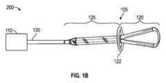
図1Aは、一実施形態による、子宮出血を抑制する一例示的システム100を示す。システム100は、産婦が分娩後に、子宮が収縮しない子宮弛緩を発症した場合に起こりうる子宮出血を軽減するか完全に止めるように機能する。子宮出血を抑制することにより、子宮からの失血の総量が実質的に抑えられ、産婦に対して輸血又は子宮摘出を行うことの必要性が低減されうる。図1Aの実施形態では、システム100は、子宮への開口を封止して、子宮内の圧力を変化させることにより、子宮の収縮を促進する。圧力の変化により、子宮内に真空が発生し、その結果、子宮壁に均一な機械的刺激が与えられて、組織のタンポナーデ及び収縮運動が促進される。図1Aの実施形態では、システム100は、挿入可能器具105、ポンプ110、及び収集容器115を含む。1A illustrates an
挿入可能器具105は、子宮に挿入されて、ポンプ110によって与えられる圧力変化を伝達するように構成されている。図1Aの実施形態では、挿入可能器具105は経膣で(膣を通って)送達され、挿入可能器具105の遠位部120が子宮内に配置され、挿入可能器具105の近位部125は子宮の外にとどまる。遠位部120は可撓構造であってよく、子宮の解剖学的構造に順応する。遠位部120と近位部125との間の封止材122によって、子宮の開口に封止を形成することが可能である。挿入可能器具105の近位部125は、ポンプ110と連結されている。図33は、膣管189内の、頸部の開口186における封止材122の例示的配置を示しており、遠位部120が子宮188内に位置している。幾つかの実施形態では、挿入可能器具105は、子宮内への挿入可能器具105の挿入を容易にするシースを有してよく、更に、ポンプ110から子宮へと空気流がつながるのが早すぎないようにすることが可能である。The
ポンプ110は、子宮内に真空を生成する圧力変化を発生させる。図1Aの実施形態では、ポンプ110は、挿入可能器具105の近位部125と連結されている。幾つかの実施形態では、連結チューブ130が近位部125とポンプ110とに取り付けられており、これによって、ポンプ110と挿入可能器具105とが連結されている。幾つかの実施形態では、収集チャンバ115は、連結チューブ130に沿ってポンプ110と近位部125との間に位置して、後で詳述するように、血液がポンプ110に入るのを防いでいる。幾つかの実施形態では、連結チューブ130は方向制御弁を含み、これは、流体が一方向に流れることを可能にし、流体が逆方向に流れることを防ぐ。例示的連結チューブ130を図35に示す。チューブ130のコネクタ147が、挿入可能器具105のコネクタ148と嵌合するように構成されている。The
ポンプ110は、作動すると空気流を発生させ、この空気流は、挿入可能器具105のチャネル及び/又は開口を通って子宮まで送られる。一般に、真空ポンプは、封止された空間から分子を取り出して後に不完全真空を残すように構成されている。子宮は、器具105が配置されると(例えば、封止材122によって)封止される為、ポンプ110による空気流によって子宮内の圧力が低下し、これによって、子宮内の圧力が子宮の外の大気圧より低くなる(例えば、1気圧未満の圧力になる)。この真空によって確実に、空気流が子宮から挿入可能器具105を通ってポンプ110に向かって単一方向に移動する。幾つかの実施形態では、ポンプ110は、60~150mmHg(例えば70~90mmHg、例えば約80mmHg)の真空圧を与えるように構成されてよい。子宮内の真空によって、子宮壁に均一な機械的刺激が与えられて、子宮壁のタンポナーデ、動脈血管収縮、及び収縮運動が促進される。更に、真空が生成されることにより、子宮内の生物学的物質を取り除くことが可能になる。生物学的物質として、血液、組織等があってよい。ポンプ110は、電動(自動)運転されてよく、或いは手動運転されてよい。ポンプ110が手動運転される実施形態では、ポンプ110は、第1の状態では、子宮内に真空を発生させることが可能であり、第2の状態では、子宮内の真空を維持しながら生物学的物質を収集容器115に引き込むことが可能である。When activated, the
収集容器115は、子宮から取り除かれた生物学的物質を集める。図1Aに示すように、収集容器115は、ポンプ110と一直線に接続されてよい。挿入可能器具105の近位部125は、連結チューブ130で収集容器115及びポンプ110と連結されている。この実施形態では、ポンプ110が作動すると、流体(例えば、空気、生物学的物質等)が連結チューブ130を通ってポンプ110に向かって流れる。生物学的物質は、ポンプ110に到達する前に連結チューブ130から取り除かれて、収集容器115に集められる。子宮から生物学的物質を集めることにより、ユーザが、子宮出血に起因する失血の量を監視及び測定することが可能になりうる。失血を監視することにより、ユーザは更に、子宮収縮が起きたかどうか、いつ起きたか、且つ/又は、どの程度まで起きたかを特定することが可能である。The
幾つかの実施形態では、システム100は、分娩後出血を監視及び/又は治療することに加えて、分娩後出血を防ぐことに使用可能である。例えば、システム100は、分娩後の産婦の子宮収縮を支援することに使用可能である。挿入可能器具105が可撓であることにより、医療提供者(例えば、看護師、内科医、外科医等)が産婦の子宮組織を腹部から触診して、子宮が収縮したかどうか、及び/又はいつ収縮したかを検出することが可能である。更に、挿入可能器具105が可撓であることにより、他の膣壁又は膣組織の修復外科手術が行われている間に挿入可能器具105を折り畳んで曲げて配置することが可能である。図32は、器具105の遠位部120が子宮への挿入に備えて手で折り畳まれる様子を示す。In some embodiments, the
幾つかの実施形態では、挿入可能器具105は、子宮の外にとどまって膣管又は頸管(例えば、上部膣管、頸部外口、又はそれらに隣接する組織)に挿入されるように構成されてよい。封止材122は、膣口又は頸部開口と子宮との間に封止を形成することが可能である。封止を形成することにより、ポンプ110による空気流によって子宮内の圧力が下がって子宮の外の大気圧より低くなり、子宮内に真空が生成されることが可能である。前述のように、これによって、子宮壁に均一な機械的刺激が与えられて、子宮壁のタンポナーデ、動脈血管収縮、及び収縮運動が促進される。In some embodiments, the
図1Bは、別の実施形態による、子宮出血を抑制するシステム200を示す。システム200は、システム100と似ており、異なるのは、別個の収集チャンバを含まない点である。従って、システム200は、挿入可能器具105及びポンプ110を含む。挿入可能器具105の近位部125は、連結チューブ130でポンプ110と連結されている。この実施形態では、収集容器はポンプ110と一体化されてよく、流体(例えば、空気、生物学的物質等)が連結チューブ130を通り抜けてポンプ110に流れ込み、ポンプ110内で、生物学的物質がポンプ110の別の一区画に集められる。この、生物学的物質を集める区画は、ポンプ110から取り外し可能であってよい。このことは、医療提供者が、集められた生物学的物質の量を監視することの助けになりうる。1B shows a
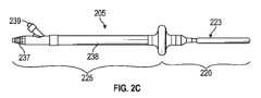
器具105に似ている別の実施形態である挿入可能器具205の詳細図を図2A-2Iに示す。挿入可能器具205は、近位部225、遠位部220、及びそれらの間の封止材222を含む。A detailed view of
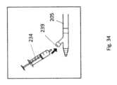
近位部225は、真空チャネル231を収容する細長ボディ238又はシャフトと、チャネル231をポンプに接続する為のコネクタ237と、膨張チャネル236と、膨張チャネル236を介して膨張媒体を封止材222に導入する為の弁付きポート239と、を含む。幾つかの実施形態では、膨張チャネル236及び真空チャネル231は互いに隣接して且つ/又は平行に延びてよい。弁付きポート239内の弁は、例えば、チェック弁であってよく、これは、シリンジが係合していない場合には流体流を通さず、シリンジが係合している場合には開いて流体流を通す。図34は、膨張媒体を導入する為に弁付きポート239に挿入されるように構成された一例示的シリンジ234を示す。The
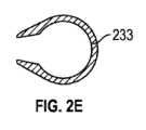
図2A~2Iに戻ると、遠位部220は可撓ループ状部分223を含み、これは、子宮に送達されるときはしぼみ、その後、自己膨張して、子宮になじむループ形状になる。更に、ループ状部分223は、内側ループ状部分232及びシールド233を含む。内側ループ状部分232は、近位部225と連続しており、近位部225に流体接続されている。内側ループ状部分232は、その内周部に複数の穴229を含み、これは(真空チャネル231との接続を介して)穴229を通して真空を与える為である。例えば、10~30個の穴229(例えば20個の穴229)があってよい。複数の穴229は、使用中に1つ以上の穴が塞がった場合の為の冗長性を備えることに役立ちうる。シールド233は、内側ループ状部分232の外周部に順応し、外周部の周囲に折り重なることが可能である。例えば、シールド233は、内側ループ状部分232の外周部のうちの270~320°の部分の周囲に広がってよい。更に、シールド233のエッジは、内側ループ状部分232より0.02~0.20”の距離だけ(例えば0.04~0.15”だけ、例えば約0.08”だけ)半径方向内側に延びてよい。シールド233のオーバハングしたエッジは、有利なことに、真空が穴229を通して引き込まれる際に穴229が組織によって塞がれないように保護されることに役立ちうる。Returning to FIGS. 2A-2I, the
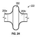
封止材222は、円盤状の中央部分292と、テーパ状の近位端293a及び遠位端293bとを有してよい。封止材222は、例えば、弁付きポート239を介して膨張させる膨張式バルーンであってよい。封止材222を膨張させる為に使用する流体の体積は、例えば、30~200cc(例えば40~120cc、例えば約60cc)であってよい。The
幾つかの実施形態では、(例えば、システム200で使用される)挿入可能器具は別の形状(即ち、ループ状ではない形状)であってよく、且つ/又は、別個のシールドがない状態で使用されてよい。例えば、図3~13は、様々な例示的挿入可能器具を示す。図3~13の器具は、(複数の異なる穴により)周囲の流体を吸引することと、同時に、組織及び大きな凝血塊が流れを止めるほど穴に近づくのをリッジ及び/又はリップで防ぐことと、を可能にするように設計されてよい。これらの複数の穴は、有利なことに、幾つかの穴が塞がった場合に備えて冗長性を可能にすることと、それらの穴全体に真空負荷を分散させることと、の両方を行うことにより、穴が組織及び/又は凝血塊で塞がるのを防ぐことが可能である。図3~13に示した器具はいずれも、例えば、単一材料(例えば、ポリウレタン等の熱可塑性材料)から押し出されてよい。そのような単一押し出しは、有利なことに、可撓性及び剛性を実現しながら設計のコストを低く抑えることが可能である。幾つかの実施形態では、図3~13に示した器具は、複数の押出型材、及び/又はデュロメータ硬度が様々であって最適設計の為に一緒に溶融される成形部品で作られてよい。押出部品の穴の形成は、例えば、ドリリング、パンチング、レーザ、又はウォータージェット切断によって行われてよい。In some embodiments, the insertable instruments (e.g., used in system 200) may be of a different shape (i.e., not looped) and/or may be used without a separate shield. For example, FIGS. 3-13 show various exemplary insertable instruments. The instruments of FIGS. 3-13 may be designed to allow for aspirating the surrounding fluid (through multiple different holes) while at the same time preventing tissue and large clots from getting close enough to the holes to stop flow with ridges and/or lips. These multiple holes can advantageously both allow for redundancy in case some holes become blocked, and distribute the vacuum load across the holes to prevent the holes from becoming blocked with tissue and/or clots. Any of the instruments shown in FIGS. 3-13 may be extruded, for example, from a single material (e.g., a thermoplastic material such as polyurethane). Such a single extrusion can advantageously keep the cost of the design low while providing flexibility and rigidity. In some embodiments, the devices shown in Figures 3-13 may be made of multiple extrusions and/or molded parts of varying durometers that are fused together for optimal design. Holes in the extrusions may be formed by drilling, punching, laser, or water jet cutting, for example.
図3は、一例示的挿入可能器具305を示す。器具305は、ほぼ直線状の(即ち、ループ状ではない)細長シャフト333を含む。シャフト333の側壁には、中心真空チャネル307からその外側にかけて複数の穴301が延びている(これは、即ち、それらの穴を通して真空を印加する為である)。ウィング又はリッジ331がシャフト333から半径方向に、且つシャフト333の長さに沿って延びている。シャフト333の長さに沿って延びるほぼV字形の溝がリッジ331間に形成されるように、リッジ331は互いに対して角度が付けられている。リッジ331の最も外側のエッジは丸みがつけられていてよく、且つ/又は人体組織を傷つけないようになっていてよい。幾つかの実施形態では、図3に示すように、4つのリッジ331によって器具305の断面がほぼ「X」字形になるようにリッジ331が配置されてよい。更に、穴301は、リッジ331間(の、例えば、V字形の溝の底即ち頂点)に配置されてよい。リッジ331は、組織が穴301に吸い寄せられるのを防ぐことにより、真空の印加、並びに子宮からの血液除去の為に穴301を空けておくことに役立ちうる。更に、穴301は、シャフト333の長手軸方向に沿って交互の位置及び/又は異なる位置に配置されてよく(即ち、隣接する溝にある穴同士が異なる軸方向位置にあってよく)、これは、組織による目詰まりを防ぐことと、器具305の安定性を維持することと、の両方に役立つ。FIG. 3 illustrates an exemplary
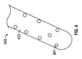
図4は、別の例示的挿入可能器具405を示す。器具405は、器具305のように、ほぼ直線状のシャフト433を含み、複数の穴401がその側壁を貫通して延びている。穴401は、シャフト433に沿ってランダムに配置されている。更に、器具405は、表面にリッジを含んでよく、且つ/又は穴401の周囲に隆起したフィーチャを含んでよく、これは、真空の印加時に組織が穴401を塞ぐのを防ぐことを支援する為である。Figure 4 illustrates another exemplary
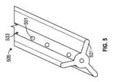
図5は、別の例示的挿入可能器具505を示す。器具505は器具305と似ているが、シャフト533は長手方向リッジ531を3つだけ含み、リッジ531間に穴501がある。Figure 5 shows another exemplary
図11は別の例示的器具1105を示しており、これは器具505と似ているが、各リッジ1131から半径方向に延びる鋭いナイフ状エッジ1111を含む。エッジ1111は、器具1105の円周方向を向くように中に曲がっており、これは、(例えば、図11の時計回り方向に)器具1105をねじったり回転させたりする際に凝血塊を突っ切ることを支援する為である。11 illustrates another
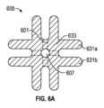
図6A~6Bは、別の例示的挿入可能器具605を示す。器具605は器具305と似ており、異なるのは、シャフト633の4つの面のそれぞれに2つの平行なリッジ631a、bを含む点である。図に示すように、リッジ631a、bの各ペアは、隣接するペアから約90度離れて配置されてよい。穴601は、平行なリッジ631a、bの各ペアの個々のリッジ631a、bの間のシャフト633内を延びてよい。更に、幾つかの実施形態では(図6A~6Bに示すように)、穴601は、貫通穴であってよく、それによって、シャフト633の一方の側から真空チャネル607を通って別の側まで完全に突き抜けることが可能である。しかしながら、隣接する穴601同士は、(図6Bに示すように)長手軸方向にオフセットしていてよい。これは、器具605の保全性を確保する為である。6A-6B show another exemplary
図7は別の例示的挿入可能器具705を示しており、これは器具605と似ており、異なるのは、リッジ731a、731bのペアを3つだけ含む点である(各ペアは、隣接するペアから約120度離れて配置されている)。穴701は、リッジ731a、bの各ペアの個々のリッジ731a、bの間のシャフト733内に同様に配置されてよい。Figure 7 shows another exemplary insertable device 705, which is similar to
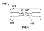
図8は別の例示的挿入可能器具805を示しており、これは器具605と似ており、異なるのは、リッジ831a、bのペアを2つだけ含む点である(これらのペアは、互いに対して約180度離れて配置されている)。リッジ831a、bのペアの個々のリッジ831a、bの間のシャフト833内の穴801は、器具の一方の側から中心真空チャネル807を通ってもう一方の側まで延びる貫通穴であってよい。挿入可能器具805は、互いに対して約180度離れている2組のリッジしかないことから、ほぼ平坦でありうる。この設計により、一方向(即ち、短軸方向)の可撓性即ち曲げやすさが別の方向(即ち、長軸方向)に比べて強化されうる。8 shows another exemplary
図9は別の例示的挿入可能器具905を示しており、これは、ほぼ直線状であり、複数の穴901を有するシャフト933を含み、穴901は、シャフト933の側壁内を中心真空チャネル907からシャフト933の外側まで延びている(これは即ち、穴901を通して真空を印加する為である)。突起991が、シャフト933の長さにわたって、シャフト933から半径方向に延びている。器具905は4つの突起を含み、これらは互いに対してほぼ90度離れて配置されている。更に、突起991の最も外側の先端は、それぞれが、三日月形の断面を有する円周方向の拡張部分995を含んでよい。拡張部分995は、器具905の周囲を円周方向に延びている(これは即ち、器具905の外形を、実質的に人体組織を傷つけない円形にする為である)。拡張部分995同士の間、並びに突起991と拡張部分995との間の開放空間993により、有利なことに、真空が穴901に到達することを可能にでき、一方、拡張部分995が円周方向の大きな覆いとなることにより、組織が穴901の上に崩れ落ちるのを防ぐことが可能である。幾つかの実施形態では、拡張部分995は鋭い内側エッジ997を含んでよく、これにより、器具905を時計回り又は反時計回りの方向にねじることが凝血塊を突っ切ることに役立ちうる。9 shows another exemplary
図10は別の例示的挿入可能器具1005を示しており、これは器具905と似ており、異なるのは、突起1091を3つだけ含む点である(これらは、例えば、互いに対してほぼ120度離れて配置されている)。Figure 10 shows another exemplary
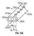
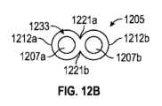
別の例示的挿入可能器具1205を図12A~12Bに示す。器具1205はシャフト1233を含み、これはほぼ直線状であって、隣り合って平行に延びる2つの管状セクション1212a、1212bを含む。各管状セクション1212a、bは、その中を延びる真空チャネル1207a、bを含む。2つの管状セクション1212a、bの間の接合によって、それらの間に長手方向の谷間1221a、bが形成されており、そこに穴1201が配置されてよい(即ち、穴1201は2つの真空チャネル1207a、bとつながっている)。長手方向の谷間1221a、b内に穴1201を配置することは、有利なことに、組織が穴1201に引き込まれないようにすることに役立ちうる。幾つかの実施形態では、真空チャネル1207a、bのそれぞれの径dvは3~6mm(5mm等)であってよく、真空チャネル1207a、bの間の距離dbは1~3mm(1.5mm等)であってよく、穴1201の径は2~5mm(3mm等)であってよい。 Another exemplary
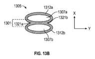
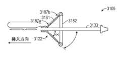
別の例示的挿入可能器具1305を図13A~13Cに示す。器具1305は器具1205と似ており、異なるのは、シャフト1333の管状セクション1312a、bが部分的に平らになっていることによって、真空チャネル1307a、bが楕円状になっていて、谷間1321a、bがより深くなっている点と、穴1301の断面が細長い点である(但し、当然のことながら、穴1301の断面は同様に円形であってよい)。幾つかの実施形態では(図13Aに示すように)、穴1301は、一方の側から他方の側に延びてよい貫通穴であってよい。楕円形状の向きによって、選択的な曲げが有利に実現されうる。例えば、図13Bを参照すると、Y方向で定義される平面(即ち、前頭面)が、産婦が仰向けになっている分娩台に平行な状態で、器具1305が子宮に挿入されてよい。そして選択的な屈曲/曲げの方向は(前頭面に垂直な)X方向になり、これは子宮の解剖学的湾曲と一致する。Another exemplary
図36~37を参照すると、器具1205、1305(又は同様の器具)の2つの管状部材1212、1312の間に形成された谷間1221、1321は、深さ(dc)と角度(α)で定義されてよい。角度αは、谷間1221、1321の底又は底の近くにある頂点で交わる直線によって形成される。深さdcは、角度の頂点から管状部材1212、1312の最上面まで測定される。器具1205、1305を再利用するのであれば、角度αが大きいほど、谷間1221、1321をクリーニングしやすくなる。しかしながら、角度αが大きいほど、覆い被さった組織が垂れ下がって、谷間1221、1321の底にある穴を塞ぐことにつながる可能性もある。角度αが小さいほど、覆い被さった組織が垂れ下がって穴を塞ぐことが起こりにくくなりうるが、谷間1221、1321の底が狭くなるほど、谷間が凝血塊で埋まることが起こりやすくなる。更に、谷間1221、1321が狭くなるほど、再利用する場合の器具1205、1305のクリーニングが困難になりうる。そこで、谷間1221、1321の深さdcは、0.02~0.20”(例えば0.05~0.12”)であってよい。更に、谷間1221、1321の角度αは10~80度(例えば20~65度)であってよい。これらの深さdc及び角度αであれば、有利なことに、器具1205、1305の適正なクリーニングを可能としながら、血液によっても垂れ下がった組織によっても塞がれないようにすることが可能である。 36-37, the
図13Cは、器具1305の変形形態(1305a~1305j)を示す。変形形態1305a、1305b、1305e、及び1305fは他の変形形態より平らであり(即ち、Y方向の厚さがX方向の厚さより小さく)、その為、穴1301はより薄い断面を貫通して延びる。対照的に、変形形態1305c、1305d、1305g、及び1305hは、穴1301がより厚い断面を貫通して延びる(これは、Y方向の厚さがX方向の厚さより大きい為である)。(変形形態1305c、1305d、1305g、及び1305hの場合のように)穴1301がより厚い断面を貫通して延びることにより、接近する子宮面の2つの面と位置合わせされることがより容易に可能になり、それによって、それらの2つの面から流体を吸い出すことが促進される。幾つかの実施形態では、図13A~13Cの器具のY方向の高さに対するX方向の幅の比(又はその逆の比)が1.4~2.3であってよく、それによって選択的な曲げが可能になる。13C shows variations (1305a-1305j) of the
図3~13の挿入可能器具はいずれも、挿入中及び使用中に子宮壁を損傷しないようにテーパ状の且つ/又は人体組織を傷つけない遠位先端部を有してよい。例えば、図14は一例示的遠位先端部1461を示す。遠位先端部1461は、挿入可能器具の他の部分(例えば、挿入可能器具のシャフト)の径と同等以下の径であってよい。同様に、一例示的先端部661を図6Bに示す。先端部661は、リッジ631が当接し且つ/又はそこで終わる円錐形状を有してよく、これにより、リッジ631のいずれの遠位端も組織に直接接触することがない。図14及び6Bに示すように、幾つかの実施形態では、中心真空チャネル1407、607が(先端部1461、661を含む)器具全体にわたって延びてよく、これは、例えば、遠位端に更なる真空ポートを設ける為であり、且つ/又は器具のフラッシング又はクリーニングを可能にする為である。図15A~15Bを参照すると、幾つかの実施形態では、先端部1561は、子宮に穴を開けないように組織1515との係合中につぶれることが可能なソフトドームであってよい(図15Aから図15Bにかけてつぶれる様子を示す)。幾つかの実施形態では、ドーム先端部1561は中空であってよい。別の実施形態では、ドーム先端部1561は、組織との係合に最適化された可撓性又は柔らかさをもたらす、柔らかいスポンジ状材料又はモールドウェビングを中に含んでよい。Any of the insertable instruments of FIGS. 3-13 may have a tapered and/or atraumatic distal tip to avoid damaging the uterine wall during insertion and use. For example, FIG. 14 shows an exemplary
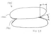
図16は、別の例示的挿入可能器具1605を示す。器具1605は、近位球状構造1616及び遠位球状構造1618を含む。(真空チャネルに接続する為の)穴1601が、近位球状構造1616と遠位球状構造1618との間に形成された谷間1619に配置されている。球状構造1616、1618は、頸部を通って挿入される際には十分つぶれながらも、真空の印加時に組織が穴1601を塞ぐのを防ぐのに十分な剛性を備えた柔らかい材料(例えば、フォーム又はウェビング)で作られてよい。16 illustrates another exemplary
本明細書に記載の出血防止装置及びシステム(例えば、システム100又は200、及び/又は図2A~13Cに示した器具のいずれかを有するシステム)で使用する為の様々な封止材設計が可能である。例えば、封止材222は、本明細書に記載の器具のいずれにおいても使用されてよい。一実施形態では、封止材222は、器具1305のシャフト1333に沿って配置されてよい。同様に、図17~30は、本明細書に記載の器具のいずれにおいても使用されてよい、幾つかの様々な例示的封止材設計を示している。Various sealant designs are possible for use with the bleeding prevention devices and systems described herein (e.g.,
図17A~17Bは、封止材1722を有する挿入可能器具1705を示す。封止材1722は、フォーム材料1771を中に有する薄い高順応性シース1719で作られてよい。ベント穴又はスリット1717がシース1719の近位端を貫通して延びてよく、これにより、空気がフォーム材料1771に入って封止材1722を膨らませることが可能になる。図17Bに示すように、封止材1722は、(体内に挿入する前に手のひら又は指で圧迫して)つぶすことが可能であり、その後、体内に入ってから、解剖学的構造に順応するように膨らませることが可能である。幾つかの実施形態では、封止材1722は、封止材1722の膨張を支援する為に、(例えば、上述のように真空内腔と平行に延びる)膨張内腔に接続されてよい。別の実施形態では、封止材1722の近位端においてスリット1717を露出させることにより、膨張内腔が不要であるほとの空気取り込みが可能になる。17A-17B show an
図18は、傘形(又は円錐形)ダイヤフラム封止材1822の側面図であり、挿入可能器具のシャフト1833が中央部の上方に延びている。ダイヤフラム1822の遠位湾曲端部(又はスカート)1881は子宮に面するように(即ち、狭い端部が子宮に最も近くなるように)意図されており、一方、近位リング1882は、近位端の円形状を維持することが可能である。遠位スカート1881が頸部開口を封止することが可能であり、或いは外側リング1882が膣管又は頸管の組織を封止することが可能であり、これによって、子宮内に真空を生成することが可能になる。幾つかの実施形態では、外側リング1882が膣管又は頸部壁の組織を圧迫するか、且つ/又はこれに連続的に半径方向に接触することにより、子宮内の封止を保持することが可能である。18 is a side view of an umbrella-shaped (or cone-shaped)
図30A~30Dは、挿入可能器具1822に似ている挿入可能器具3005を示しており、これは、傘形(又は円錐形)ダイヤフラム封止材3022を含み、挿入可能器具3055のシャフト3033が封止材3022の中央部の上方に延びている。封止材1822と比べると、封止材3022の遠位スカート3081は、シャフト3033に対する角度αが小さい(図30Aを参照)(例えば、角度αは30~60度(例えば約45度)であってよい)。近位リング3082は、重いか堅いリングであってよい(例えば、径が2~10mm(例えば約5mm)の固体ポリマーリングであってよい)。堅いリング3082は、有利なことに、組織がリング3082の周囲でつぶれても円形状又は楕円形状を維持することが可能である。遠位スカート3081は更に、封止材1822のスカートより厚くてよい(例えば、スカート3081の壁厚は1~1.5mm(例えば約1.2mm)であってよい)。30A-30D show an
図30Bを参照すると、リング3082は、膣管又は頸管に挿入されると、膣壁又は頸部壁の組織3031に当たって固定されて、そこで器具を封止することが可能である。リング3082が堅いことは、有利なことに、リング3082の形状を面内に(即ち、シャフト3033の長手軸3037に垂直な面3035の面内に)保持することに役立ちうる。設置されてピンと張った状態にある厚いスカート3081は更に、リング3082を定位置に(長手軸3037に垂直な面3035の面内に)とどめて、リング3082が回転したり、横たわったり、且つ/又は封止しなくなったりするのを防ぐことに役立ちうる。解剖学的には、この、封止材3022の設計及び向きは、有利なことに、膣壁又は頸部壁の組織3031に対して封止を作用させるのに最適な向きを実現しうる。30B, when the
図30Cを参照すると、挿入可能器具3005のスカート3081は、シャフト3033が近位方向に引っ張られると反転するように構成されてよい。即ち、可撓スカート3081は、近位方向に力がかかると、それ自体において巻き戻され始めることが可能であり、典型的には、スカートのうちの、シャフト3033に最も近い部分から巻き戻され始めることが可能である。反転する傾向(反転に必要な力)は、例えば、スカート3081の厚さ(特にシャフト3033にちょうど隣接する部分の厚さ)によって決まりうる。更に、反転する傾向は、スカート3081とシャフト3033との間の角度αによって決まりうる。角度αが大きいほど、反転しやすい。その一方で、角度αが小さいほど、リング3082の面が横たわったり回転したりすることに対するスカート3081の抵抗力が強い。30C, the
図30Dに示すように、スカート3081の反転により、円錐形の先端部3091が形成されることが可能であり、先端部3091は、近位方向に引っ張られるにつれて膣壁又は頸部壁の組織3031を分けていく。更に、スカート3081へのリング3082の取り付けは、外側表面が除去方向に最も滑らかになるように設計されてよく、これは、膣管又は頸管に配置されている可能性のある修復縫合3098を損傷しないようにする為である。例えば、堅いリング3082へのスカート3081の取付部は、スカート3081が反転されたときには器具3005の最外径にあってよく、これにより、器具3005が近位方向に引っ込められるにつれて、スカート3081は(膣壁又は頸部壁の組織3031に対して最も浅い角度で)組織を容易に乗り越え、特に、膣壁上又は頸部壁上に修復縫合3098がある場合にはこれを容易に乗り越える。(角度αが小さくなり、堅いリング3082の径は同じままで)スカートが長くなるにつれて、組織壁に対するスカートの勾配がより浅くなり、縫合3098を乗り越えることがより容易になる。30D, eversion of the
当然のことながら、リング3082の面とシャフト3033の長手軸との間の垂直関係を維持することが有利でありうるが、その垂直関係の幾らかのバリエーションも、様々な解剖学的構造に対する自由度を可能にすることに役立ちうる。Of course, it may be advantageous to maintain a perpendicular relationship between the plane of the
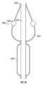
幾つかの実施形態では、スカート3081の厚さは、スカート3081の曲がりパターンが最適化されるように近位端から遠位端にかけて変化してよい。例えば、厚さは、シャフトへの取付部と堅いリングとの間の複数の特定の距離に合わせて調整されてよい。図31は、スカート3181の長さに沿って薄い部分3187a、bがある一例示的挿入可能器具3105を示す。厚さの変化は、器具の配置及び動作/封止、並びに器具の除去時の反転機構の強化の為に有利でありうる。In some embodiments, the thickness of the
図19は、カッピングカフ封止材1922の側面図であり、挿入可能器具のシャフト1933が中央部の上方に延びている。遠位リング1991は、子宮に面し、頸部開口の外側を取り囲み、膣円蓋内に落ち着くことが可能である。湾曲した近位端1993が頸部開口をカップで取り囲んで、子宮内の真空を保持する封止材を形成することが可能である。FIG. 19 is a side view of the
図20は、部分的に折り畳まれた形態の折り畳み可能封止材2022の上面図である。封止材2022は封止材1822と似ており、異なるのは、半径方向の折り目2020を含む点であり、折り目2020により、挿入時は傘形状が折り畳まれやすいことが可能であり(即ち、径がより小さい膣管又は頸管に入るように折り畳まれやすいことが可能であり)、一方、挿入後は、より大きな空間を埋めるように傘形状が広がって、子宮内の真空を保持する封止材を形成することが可能である。20 is a top view of
図21は、挿入可能器具のシャフト2133を取り巻く封止材2122の等角図である。封止材2122は、つながった複数のリング2114を有する平らな円盤状封止材であり、これらのリングにより円盤が望遠鏡のように伸びて円錐形状になることが可能である。使用時には、最も外側のリング2114が、挿入直後に、膣組織又は頸部組織をより大きな径の空間に捕捉することが可能であるが、必要であれば器具のシャフト2133を挿入し続けて子宮に入れることを可能にしうる。FIG. 21 is an isometric view of a
図22は、折り畳み式円錐形封止材2222の等角図であり、段々に並んだリッジ2221又はエッジが円周の周囲に広がっている。遠位リング2223は、子宮のほうを向くように設計されてよい。折り畳み式円錐形の設計により、器具が挿入されたときには遠位リング2223の周囲に封止が発生することが可能であり、更に、必要であれば、封止材2222を押し退けることなく、器具をより遠くまで(遠位方向に)挿入することが可能である。Figure 22 is an isometric view of a
図23A~23Bは、反転カップ形封止材2322を示す。遠位リング2331は、子宮に面し、(例えば、膣円蓋内に落ち着いた状態で)上部膣管を封止し、頸部開口の周囲を封止するように意図されている。湾曲遠位端2333は、子宮内の真空を保持することが可能である。図23Bに示すように、封止材2322は、複数のらせんリッジ及び/又は谷を含んでよく、これらは、例えば、封止材2322のより容易であって予測可能な折り畳み方法を可能にしうる。これらのリッジ及び谷によって、医師は、まだ新しい膣縫合を引き裂くことなく器具を穏やかに除去することが可能になりうる。更に、これらのリッジ及び谷は、器具の挿入の助けになりうる。これは、封止材2322を2本の指で挟んでねじってつかむことが可能であり、それによって、配置中の視認性が向上しうる為である。23A-23B show an inverted cup-shaped
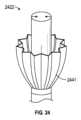
図24は反転カップ形封止材2422を示しており、これは封止材2322と似ているが、軸方向に延びるプリーツ2441を含むことにより、挿入時の封止材2422の折り畳みを容易にしている。封止材2422に使用される材料は、(例えば、挿入後に)折り畳む力が抜けると材料が自然に広がってカップ形状に戻ることが可能なように弾力性があってよい。FIG. 24 shows an inverted cup-shaped
図25はカップ形封止材2522を示しており、これは封止材2322と似ているが、異なるのは、遠位端2551がわずかに外側にラッパ状に広がっている点である。Figure 25 shows a cup-shaped
図26A~26Bは封止材2622を示しており、これは封止材2622と似ているが、異なるのは、高順応性の、ラッパ状に広がった遠位端2661を含む点であり、これは(例えば、径がより小さい膣管又は頸管に対応する為に)それ自体が巻き戻される(即ち、近位方向に巻かれる)ことが可能である。図26Aは、端部2661が広げられた状態を示しており、一方、図26Bは、端部2661が近位方向に巻かれた状態を示している。26A-
図27は封止材2722を示しており、これは、湾曲環状構造2773を支持する中央円盤2771又はダイヤフラムを含む。環状構造2773は、(例えば、頸部開口において)膣壁又は頸部壁を封止することにより、子宮内の真空を保持することが可能である。FIG. 27 shows a
図28は封止材2822を示しており、これは湾曲環状構造2883を含み、これは、近位端がシャフト2833に取り付けられて支持されており、遠位端が開放されている。Figure 28 shows a
図29は、別の例示的封止材2922を示す。封止材2922は膨張式球状部2937を含み、これは挿入可能器具のシャフト2977を封止している。球状部2937は、分娩後の頸部の開口において球状部2937が組織に対して固定されることを可能にする材料で作られてよい。幾つかの実施形態では、例えば、球状部2937は、デュロメータ硬度が中程度のシリコーン又は他の可撓材料で作られてよい。球状部2937は更に、膣管を通って頸部に挿入されることを容易にするテーパ2939を遠位端に含んでよい。球状部2937の全体形状は、有利なことに、真空が子宮内に引き込まれるときの封止を実現しうる。幾つかの実施形態では、球状部2937は、その周囲に環状の補強リング2938を含んでよい。補強リングは、球状部2937の他の部分より高い強度を有してよく、これは、球状部2937が組織壁に押し付けられたときに円形状又は楕円形状を維持するのに役立つ。幾つかの実施形態では、補強リング2938は、球状部2937の他の部分と同じ材料で作られてよいが、より厚くされてよい。FIG. 29 illustrates another
幾つかの実施形態では、球状部2937は、バランスチャンバ2940からの空気によってのみ膨張及び収縮するように構成されてよい。バランスチャンバ2940は、非常に薄くてデュロメータ硬度が柔らかい材料で作られた薄いスリーブ又はバルーンであってよい。バランスチャンバ2940は、球状部2937が圧縮された場合のみ球状部2937から空気を受け入れるように構成されてよい。バランスチャンバ2940のサイズ又は長さは、球状部2937が圧迫されてもバランスチャンバ2940の径が球状部2937より大きくならないように最適化されてよい。バランスチャンバ2940と球状部2937との間のチャネルによって、球状部2937が(例えば、器具の挿入中に行われていた圧迫が解除されて)その本来の形状に戻る際に、バランスチャンバ2940と球状部2937との間を空気が行ったり来たりすることが可能になりうる。球状部2937及びバランスチャンバ2940は、密封されているので、有利なことに、複数回使用が必要な場合のクリーニング及び滅菌が容易でありうる。In some embodiments, the
別の実施形態では、球状部2937は、膨張内腔を介して膨張可能である。更に別の実施形態では、球状部2937は、(例えば、バランスチャンバを有することなく)球状部2937の近位端にあるベント又は穴から空気を導入することにより膨張可能である。In another embodiment, the
本明細書に記載のシステム、器具、及び方法は、有利なことに、分娩後の子宮内に真空を引き込んで、子宮から血液を除去し、且つ子宮の収縮を支援することによって、分娩後出血を止めることが可能である。The systems, devices, and methods described herein can advantageously stop postpartum bleeding by drawing a vacuum in the uterus after delivery to remove blood from the uterus and assist in uterine contractions.
幾つかの実施形態では、本明細書に記載のシステム及び器具の少なくとも一部は、子宮から吸引されている血液及び流体の可視化を可能にする為に透明であってよい。In some embodiments, at least a portion of the systems and devices described herein may be transparent to allow visualization of blood and fluids being aspirated from the uterus.
本明細書に記載の器具のいずれかを使用して、出血している子宮の内部において、1~24時間以下にわたって連続的に真空が印加されてよい。幾つかの実施形態では、子宮は、真空の印加によって等圧状態に保たれてよい。幾つかの実施形態では、1時間未満で(例えば、30分未満で、又は20分未満で、又は5分未満で、又は2分未満で)出血が止まりうる。Any of the devices described herein may be used to continuously apply a vacuum within the bleeding uterus for 1-24 hours or less. In some embodiments, the uterus may be kept in an isobaric state by application of the vacuum. In some embodiments, bleeding may cease in less than an hour (e.g., in less than 30 minutes, or in less than 20 minutes, or in less than 5 minutes, or in less than 2 minutes).
本明細書に記載の器具はいずれも、別個の封止部材がなくても使用可能である。即ち、組織が細長ボディ又はシャフトの周囲を直接封止することによって子宮を封止することが可能である。Any of the devices described herein may be used without a separate sealing member, i.e., the uterus may be sealed by tissue sealing directly around the elongate body or shaft.
本明細書に記載の器具はいずれも、挿入中に人体組織を傷つけないように、柔らかく丸みのあるエッジを有する遠位先端部を含んでよい。Any of the instruments described herein may include a distal tip having soft, rounded edges to avoid trauma to body tissue during insertion.
本明細書に記載の器具はいずれも、その遠位先端部に(例えば、真空内腔を通る中心線と一列に並ぶか、且つ/又は2つの内腔の中心線と並ぶ)真空穴を有してよい。そのような真空穴は、有利なことに、先端部近くの血液及び凝血塊へのアクセスに役立つことが可能であり、且つ/又は器具の先端部までの(例えば、ワイヤブラシによる)クリーニングのしやすさを促進することが可能である。Any of the instruments described herein may have a vacuum hole at its distal tip (e.g., aligned with a centerline through the vacuum lumen and/or aligned with the centerlines of two lumens). Such a vacuum hole can advantageously aid in accessing blood and clots near the tip and/or facilitate ease of cleaning (e.g., with a wire brush) to the tip of the instrument.
本明細書に記載の器具はいずれも、局所的解剖学的構造に順応するように可撓であってよい。Any of the devices described herein may be flexible to conform to local anatomy.
本明細書に記載の器具はいずれも、第1の軸の方向が第2の軸の方向より可撓であってよい。例えば、器具は、前頭面に垂直な軸の方向が、矢状面に垂直な軸の方向より可撓であってよく、このことは、有利なことに、器具が子宮の自然な上向きの角度に順応することに役立ちうる。或いは、本明細書に記載の器具はいずれも、前頭面に垂直な軸の方向にも、矢状面に垂直な軸の方向にも同等に可撓であってよく、これにより、例えば、子宮内に器具を、向きを気にせずに配置することが可能である。Any of the devices described herein may be more flexible along a first axis than along a second axis. For example, the device may be more flexible along an axis perpendicular to the coronal plane than along an axis perpendicular to the sagittal plane, which may advantageously help the device conform to the natural upward angle of the uterus. Alternatively, any of the devices described herein may be equally flexible along an axis perpendicular to the coronal plane as along an axis perpendicular to the sagittal plane, which may allow, for example, the device to be placed in the uterus without regard to orientation.
当然のことながら、一実施形態に関して本明細書に記載された任意の特徴が、別の実施形態に関して本明細書に記載された任意の要素を置き換えてよく、或いはその要素に追加して用いられてよい。It will be appreciated that any feature described herein with respect to one embodiment may be substituted for, or used in addition to, any element described herein with respect to another embodiment.
本明細書において、ある特徴又は要素が別の特徴又は要素の「上に(on)」あると言及された場合、その特徴又は要素は、直接その別の特徴又は要素に接していてよく、或いは、介在する特徴及び/又は要素が存在してもよい。これに対し、ある特徴又は要素が別の特徴又は要素の「直接上に(directly on)」あると言及された場合、介在する特徴及び/又は要素は存在しない。又、当然のことながら、ある特徴又は要素が別の特徴又は要素に「接続されている(connected)」、「取り付けられている(attached)」、又は「結合されている(coupled)」と言及された場合、その特徴又は要素は、直接その別の特徴又は要素に接続されているか、取り付けられているか、結合されていてよく、或いは、介在する特徴又は要素が存在してもよい。これに対し、ある特徴又は要素が別の特徴又は要素に、「直接接続されている(directly connected)」、「直接取り付けられている(directly attached)」、又は「直接結合されている(directly coupled)」と言及された場合、介在する特徴又は要素は存在しない。そのように記載又は図示された特徴及び要素は、1つの実施形態に関して記載又は図示されているが、他の実施形態にも当てはまってよい。又、当業者であれば理解されるように、ある構造又は特徴が別の特徴に「隣接して(adjacent)」配置されていて、その構造又は特徴が言及された場合、その言及は、隣接する特徴と部分的に重なり合うか、隣接する特徴の下層となる部分を有してよい。In this specification, when a feature or element is referred to as being "on" another feature or element, the feature or element may be directly adjacent to the other feature or element, or there may be intervening features and/or elements. In contrast, when a feature or element is referred to as being "directly on" another feature or element, there are no intervening features and/or elements. It should also be understood that when a feature or element is referred to as being "connected," "attached," or "coupled" to another feature or element, the feature or element may be directly connected, attached, or coupled to the other feature or element, or there may be intervening features or elements. In contrast, when a feature or element is referred to as being "directly connected," "directly attached," or "directly coupled" to another feature or element, there are no intervening features or elements present. Features and elements so described or illustrated may be described or illustrated with respect to one embodiment, but may also apply to other embodiments. Also, as will be understood by those skilled in the art, when a structure or feature is described as being "adjacent" to another feature, the reference may include portions that overlap or underlie the adjacent feature.
本明細書で用いられる用語は、特定の実施形態を説明することだけを目的としており、本発明を限定するものではない。例えば、本明細書において使用される単数形「a」、「an」、及び「the」は、文脈上明らかに矛盾する場合を除き、複数形も同様に包含するものとする。更に、当然のことながら、「comprises(含む)」及び/又は「comprising(含む)」という語は、本明細書で使用された際には、述べられた特徴、手順、操作、要素、及び/又は構成要素の存在を明記するものであり、1つ以上の他の特徴、手順、操作、要素、構成要素、及び/又はこれらの集まりの存在又は追加を排除するものではない。本明細書では、「及び/又は(and/or)」という用語は、関連付けられて列挙されたアイテムのうちの1つ以上のアイテムのあらゆる組み合わせを包含するものであり、「/」と略記されてよい。The terms used herein are for the purpose of describing particular embodiments only and are not intended to be limiting. For example, the singular forms "a," "an," and "the" as used herein are intended to include the plural forms as well, unless the context clearly indicates otherwise. It should be understood that the terms "comprises" and/or "comprising," as used herein, specify the presence of stated features, steps, operations, elements, and/or components, but do not exclude the presence or addition of one or more other features, steps, operations, elements, components, and/or groups thereof. As used herein, the term "and/or" includes any combination of one or more of the associated listed items and may be abbreviated as "/."
「下に(under)」、「下方に(below)」、「下方の(lower)」、「上方の(over)」、「上方の(upper)」等のような空間的に相対的な語句は、本明細書では、図面に示されるような、1つの要素又は特徴と別の要素又は特徴との関係を説明する場合に説明を簡単にする為に使用されてよい。当然のことながら、この空間的に相対的な語句は、使用時又は操作時の器具の、図面で描かれる向きに加えて、それ以外の向きも包含するものとする。例えば、図面内の器具が反転された場合、別の要素又は特徴の「下に(under)」又は「真下に(beneath)」あると記載された要素は、その別の要素又は特徴の「上に(over)」方向づけられることになる。従って、例えば、「下に(under)」という語句は、「上に(over)」及び「下に(under)」の両方の向きを包含しうる。本装置は、他の方向づけ(90度回転又は他の方向づけ)が行われてよく、それに応じて、本明細書で使用された空間的に相対的な記述子が解釈されてよい。同様に、「上方に(upwardly)」、「下方に(downwardly)」、「垂直方向の(vertical)」、「水平方向の(horizontal)」等の用語は、本明細書では、特に断らない限り、説明のみを目的として使用される。Spatially relative terms such as "under," "below," "lower," "over," "upper," and the like may be used herein for ease of description when describing the relationship of one element or feature to another element or feature as shown in the drawings. It should be understood that the spatially relative terms are intended to encompass other orientations of the device in use or operation in addition to those depicted in the drawings. For example, if the device in the drawings were inverted, an element described as being "under" or "beneath" another element or feature would be oriented "over" that other element or feature. Thus, for example, the term "under" may encompass both the orientations of "over" and "under." The device may be otherwise oriented (rotated 90 degrees or at other orientations) and the spatially relative descriptors used herein may be interpreted accordingly. Similarly, terms such as "upwardly," "downwardly," "vertical," and "horizontal" are used herein for descriptive purposes only, unless otherwise specified.
「第1の」及び「第2の」という語句は、本明細書では様々な特徴/要素(手順を含む)を説明する為に使用されてよいが、これらの特徴/要素は、文脈上矛盾する場合を除き、これらの語句によって限定されるべきではない。これらの語句は、ある特徴/要素を別の特徴/要素と区別する為に使用されてよい。従って、本発明の教示から逸脱しない限り、第1の特徴/要素が後述時に第2の特徴/要素と称されてもよく、同様に、第2の特徴/要素が後述時に第1の特徴/要素と称されてもよい。The terms "first" and "second" may be used herein to describe various features/elements (including steps), but these features/elements should not be limited by these terms unless the context indicates otherwise. These terms may be used to distinguish one feature/element from another. Thus, a first feature/element may be referred to as a second feature/element below, and similarly, a second feature/element may be referred to as a first feature/element below, without departing from the teachings of the present invention.
本明細書及び後続の特許請求の範囲の全体を通して、別段に記述しない限りは、「含む(comprise)」という後、及びその変形である「含む(comprises)」、「含む(comprising)」等は、方法及び物品(例えば、装置(device)及び方法を含む構成及び装置(apparatus))において様々な構成要素が相互連帯して使用されてよいことを意味する。例えば、「含む(comprising)」という語は、述べられた全ての要素又はステップの包含を意味するものであって、他のあらゆる要素又はステップの排除を意味するものではないことを理解されたい。Throughout this specification and the claims that follow, unless otherwise stated, the word "comprise" and its variations "comprises," "comprising," etc., mean that various components may be used in conjunction with one another in methods and articles (e.g., devices and method-containing compositions and apparatuses). For example, the word "comprising" should be understood to imply the inclusion of all stated elements or steps, but not the exclusion of any other elements or steps.
実施例において使用される場合も含め、本明細書及び特許請求の範囲において使用されているように、且つ、特に断らない限り、あらゆる数値は、「約(about)」又は「およそ(approximately)」という語句が前置されているものとして読まれてよく、たとえ、その語句が明示的に現れていなくても、そのように読まれてよい。「約(about)」又は「およそ(approximately)」という語句は、大きさ及び/又は位置を示す場合に、記載された値及び/又は位置が、妥当な予想範囲の値及び/又は位置に収まっていることを示す為に使用されてよい。例えば、数値は、述べられた値(又は値の範囲)の±0.1%の値であってよく、述べられた値(又は値の範囲)の±1%の値であってよく、述べられた値(又は値の範囲)の±2%の値であってよく、述べられた値(又は値の範囲)の±5%の値であってよく、述べられた値(又は値の範囲)の±10%の値であってよく、他のそのような値であってよい。本明細書に記載のいかなる数値範囲も、そこに包含される全ての副範囲を包含するものとする。As used herein and in the claims, including in the examples, and unless otherwise specified, any numerical value may be read as being preceded by the term "about" or "approximately", even if the term is not explicitly present. The terms "about" or "approximately", when used to indicate a size and/or location, may be used to indicate that the stated value and/or location is within a reasonable expected range of values and/or locations. For example, a numerical value may be ±0.1% of the stated value (or range of values), ±1% of the stated value (or range of values), ±2% of the stated value (or range of values), ±5% of the stated value (or range of values), ±10% of the stated value (or range of values), or other such values. Any numerical ranges set forth herein are intended to encompass all subranges contained therein.
ここまで様々な例示的実施形態について記載してきたが、特許請求の範囲によって示される本発明の範囲から逸脱しない限り、様々な実施形態に対して、幾つかある変更のいずれが行われてもよい。例えば、記載された各種方法ステップが実施される順序は、代替実施形態では変更されてよい場合が多く、代替実施形態によっては、1つ以上の方法ステップがまとめてスキップされてもよい。装置及びシステムの様々な実施形態の任意選択の特徴が、実施形態によっては含まれてよく、実施形態によっては含まれなくてよい。従って、上述の説明は、主に例示を目的としたものであり、特許請求の範囲に明記されている本発明の範囲を限定するように解釈されるべきではない。Although various exemplary embodiments have been described above, any of a number of modifications may be made to the various embodiments without departing from the scope of the invention as set forth in the claims. For example, the order in which the various method steps described are performed may often be changed in alternative embodiments, and in some alternative embodiments, one or more method steps may be skipped altogether. Optional features of the various embodiments of the apparatus and systems may be included in some embodiments and not in other embodiments. Thus, the foregoing description is primarily for illustrative purposes and should not be construed as limiting the scope of the invention as set forth in the claims.
本明細書に含まれる実施例及び具体例は、本発明対象が実施されうる具体的な実施形態を、限定ではなく例示として示す。言及されたように、他の実施形態が利用されたり派生したりしてよく、本開示の範囲から逸脱しない限り、構造的な、或いは論理的な置換又は変更が行われてよい。本発明対象のそのような実施形態は、本明細書においては、個別に参照されてよく、或いは、「本発明」という言い方でまとめて参照されてよく、「本発明」という言い方で参照することは、あくまで便宜上であって、本出願の範囲を、実際には2つ以上が開示されていても、いずれか1つの発明又は発明概念に自発的に限定することを意図するものではない。従って、本明細書では特定の実施形態を図示及び説明してきたが、この、示された特定の実施形態を、同じ目的を達成するように作られた任意の構成で置き換えてよい。本開示は、様々な実施形態のあらゆる翻案又は変形を包含するものである。当業者であれば、上述の説明を精査することにより、上述の複数の実施形態の組み合わせ、及び本明細書に具体的な記載がない他の実施形態が明らかになるであろう。The examples and specific examples contained herein are illustrative, not limiting, of specific embodiments in which the subject matter may be practiced. As noted, other embodiments may be utilized or derived, and structural or logical substitutions or changes may be made without departing from the scope of the present disclosure. Such embodiments of the subject matter may be referred to individually herein or collectively under the term "the present invention," which is merely for convenience and is not intended to spontaneously limit the scope of the present application to any one invention or inventive concept, even if more than one is actually disclosed. Thus, although specific embodiments have been shown and described herein, the specific embodiments shown may be substituted with any configuration designed to achieve the same purpose. The present disclosure is intended to encompass any adaptations or variations of the various embodiments. Combinations of the above-described embodiments, as well as other embodiments not specifically described herein, will become apparent to those skilled in the art upon review of the above description.
Claims (8)
Translated fromJapanese遠位端において前記細長ボディに取り付けられ、子宮内に配置されるように構成された可撓ループ状部分であって、前記可撓ループ状部分はその内周部に複数の穴を含み、前記真空源の活性化は、前記細長ボディが前記子宮に挿入されたときに前記子宮をしぼませるように、前記複数の穴を通して真空を引き込むように構成されている、前記可撓ループ状部分と、
前記可撓ループ状部分の外周部の周囲に折り重なり、前記可撓ループ状部分に対して半径方向内側に広がるエッジを有するシールドであって、真空が印加されたときに組織が前記複数の穴を塞ぐことを防ぐように構成された前記シールドと、
前記細長ボディの周囲に取り付けられ、前記子宮を封止するように構成された膨張式封止材と、
を含む出血防止器具。 an elongate body configured to be connected to a vacuum source;
a flexible loop-shaped portion attached to the elongate body at a distal end and configured to be placed within a uterus, the flexible loop-shaped portion including a plurality of holes on an inner circumference thereof, and activation of the vacuum source configured to draw a vacuum through the plurality of holes to collapse the uterus when the elongate body is inserted into the uterus;
a shield having an edge that folds around an outer periphery of the flexible loop portion and extends radially inward relative to the flexible loop portion, the shield configured to prevent tissue from blocking the plurality of holes when a vacuum is applied;
an inflatable seal attached about the elongate body and configured to seal against the uterus;
Bleeding prevention devices including:
Priority Applications (1)
| Application Number | Priority Date | Filing Date | Title |
|---|---|---|---|
| JP2024148228AJP2024167344A (en) | 2018-12-10 | 2024-08-30 | Postpartum uterine bleeding device |
Applications Claiming Priority (5)
| Application Number | Priority Date | Filing Date | Title |
|---|---|---|---|
| US201862777642P | 2018-12-10 | 2018-12-10 | |
| US62/777,642 | 2018-12-10 | ||
| US201962861233P | 2019-06-13 | 2019-06-13 | |
| US62/861,233 | 2019-06-13 | ||
| PCT/US2019/065504WO2020123525A1 (en) | 2018-12-10 | 2019-12-10 | Postpartum uterine hemorrhage device |
Related Child Applications (1)
| Application Number | Title | Priority Date | Filing Date |
|---|---|---|---|
| JP2024148228ADivisionJP2024167344A (en) | 2018-12-10 | 2024-08-30 | Postpartum uterine bleeding device |
Publications (2)
| Publication Number | Publication Date |
|---|---|
| JP2022516203A JP2022516203A (en) | 2022-02-24 |
| JP7549595B2true JP7549595B2 (en) | 2024-09-11 |
Family
ID=71077542
Family Applications (2)
| Application Number | Title | Priority Date | Filing Date |
|---|---|---|---|
| JP2021555152AActiveJP7549595B2 (en) | 2018-12-10 | 2019-12-10 | Postpartum uterine bleeding device |
| JP2024148228APendingJP2024167344A (en) | 2018-12-10 | 2024-08-30 | Postpartum uterine bleeding device |
Family Applications After (1)
| Application Number | Title | Priority Date | Filing Date |
|---|---|---|---|
| JP2024148228APendingJP2024167344A (en) | 2018-12-10 | 2024-08-30 | Postpartum uterine bleeding device |
Country Status (12)
| Country | Link |
|---|---|
| US (1) | US20220022916A1 (en) |
| EP (1) | EP3893764A4 (en) |
| JP (2) | JP7549595B2 (en) |
| KR (1) | KR102837199B1 (en) |
| CN (2) | CN119949936A (en) |
| AU (1) | AU2019395364B2 (en) |
| BR (1) | BR112021010950A2 (en) |
| CA (1) | CA3122759A1 (en) |
| CO (1) | CO2021008264A2 (en) |
| MX (2) | MX2021006628A (en) |
| SG (1) | SG11202105797TA (en) |
| WO (1) | WO2020123525A1 (en) |
Families Citing this family (17)
| Publication number | Priority date | Publication date | Assignee | Title |
|---|---|---|---|---|
| US12076047B2 (en) | 2012-03-15 | 2024-09-03 | Alydia Health, Inc. | Uterine hemorrhage controlling system and method |
| EP3796853A4 (en) | 2018-05-19 | 2022-03-30 | Crafton, Ashley | HANNAH CERVICAL MUG |
| JP2022550659A (en)* | 2019-07-24 | 2022-12-05 | アリディア ヘルス,インク. | Abnormal uterine bleeding control system and method |
| CN112137677A (en)* | 2020-10-21 | 2020-12-29 | 上海市第十人民医院 | Vaginal blocking device for gynecological laparoscopic surgery |
| USD1048407S1 (en)* | 2021-02-04 | 2024-10-22 | Angiodynamics, Inc. | Manual mechanical aspiration device |
| USD1048408S1 (en)* | 2021-02-04 | 2024-10-22 | Angiodynamics, Inc. | Handle for a manual mechanical aspiration device |
| EP4085855A1 (en)* | 2021-05-04 | 2022-11-09 | Hemosquid | Hemostatic device |
| CA3218092A1 (en) | 2021-05-04 | 2022-11-10 | Hemosquid | Hemostatic device |
| JP2024518531A (en) | 2021-05-13 | 2024-05-01 | アーリー バード メディカル,インコーポレーテッド | Retractable surgical drain and method for use - Patents.com |
| EP4241708A1 (en) | 2022-03-09 | 2023-09-13 | Hemosquid | Hemostatic device |
| EP4241707A1 (en) | 2022-03-09 | 2023-09-13 | Hemosquid | Hemostatic device |
| US11839408B2 (en)* | 2022-04-06 | 2023-12-12 | Lucie Medical Inc. | Systems, devices, and methods for uterine hemostasis |
| CN114917004A (en)* | 2022-05-11 | 2022-08-19 | 重庆市武隆区妇幼保健院 | Negative pressure tamponade device for postpartum uterine atony |
| CN115737044A (en)* | 2022-11-17 | 2023-03-07 | 浙江医链医疗科技有限公司 | Uterus hemostat |
| US11849971B1 (en)* | 2022-11-28 | 2023-12-26 | Nemow Llc | Uterine toner device to prevent and control postpartum hemorrhage |
| CN115969450A (en)* | 2022-12-15 | 2023-04-18 | 浙江医链医疗科技有限公司 | A lockable pull-out structure dedicated to a uterine hemostat |
| WO2024233441A1 (en)* | 2023-05-11 | 2024-11-14 | Crafton Ashley Camille | Hannah cervical cup |
Citations (6)
| Publication number | Priority date | Publication date | Assignee | Title |
|---|---|---|---|---|
| JP2001510071A (en) | 1997-07-17 | 2001-07-31 | エスアールエス・メディカル・システムズ,インコーポレイテッド | Fluid bypass valve |
| JP2010246911A (en) | 2009-04-16 | 2010-11-04 | Tyco Healthcare Group Lp | Iupc introducer |
| JP2015512275A (en) | 2012-03-15 | 2015-04-27 | インプレス テクノロジーズInpress Technologies | Uterine bleeding control system and method |
| US20170281231A1 (en) | 2016-04-01 | 2017-10-05 | University Of Utah Research Foundation | Uterine contraction device |
| US20180055523A1 (en) | 2016-08-24 | 2018-03-01 | Inpress Technologies, Inc. | Uterine hemorrhage controlling system and method |
| JP2018533461A (en) | 2015-11-17 | 2018-11-15 | プレビボ ジェネティクス インコーポレイテッド | Method of harvesting and processing in vivo formed human embryos |
Family Cites Families (18)
| Publication number | Priority date | Publication date | Assignee | Title |
|---|---|---|---|---|
| US3670732A (en)* | 1970-05-11 | 1972-06-20 | Ralph R Robinson | Vacuum curette |
| US3923051A (en)* | 1974-03-18 | 1975-12-02 | Samuel Soichet | Inflatable intrauterine contraceptive device for postpartum use |
| US4217904A (en)* | 1977-03-25 | 1980-08-19 | Zahorsky Carroll L | Drain construction |
| US4317452A (en)* | 1980-02-04 | 1982-03-02 | C. R. Bard, Inc. | Body fluid drain |
| US4573965A (en)* | 1984-02-13 | 1986-03-04 | Superior Plastic Products Corp. | Device for draining wounds |
| US4950232A (en)* | 1987-08-11 | 1990-08-21 | Surelab Superior Research Laboratories | Cerebrospinal fluid shunt system |
| US7658735B2 (en)* | 1999-03-22 | 2010-02-09 | Spehalski Stephan R | Steerable wound drain device |
| JP4472824B2 (en)* | 2000-02-16 | 2010-06-02 | テルモ株式会社 | Intravascular catheter |
| EP1720595B1 (en)* | 2004-03-03 | 2011-05-11 | C.R.Bard, Inc. | Loop-tip catheter |
| US8348856B1 (en)* | 2008-12-16 | 2013-01-08 | Zanetta Malanowska-Stega | Simultaneous multiple method out-patient uterus biopsy device and method |
| US8864728B2 (en)* | 2008-12-31 | 2014-10-21 | Kci Licensing, Inc. | Multi-conduit manifolds, systems, and methods for applying reduced pressure to a subcutaneous tissue site |
| EP2397087A3 (en)* | 2009-01-30 | 2013-08-14 | Cytyc Corporation | Cervical opening sealing devices |
| US8574218B2 (en)* | 2010-05-10 | 2013-11-05 | Cook Medical Technologies Llc | Catheter, fluid conveying method, and percutaneous procedure |
| US10064651B2 (en)* | 2012-03-15 | 2018-09-04 | Inpress Technologies, Inc. | Uterine hemorrhage controlling system and method |
| EP3021768B1 (en)* | 2013-07-19 | 2020-08-19 | DePuy Synthes Products, Inc. | An anti-clogging device for a vacuum-assisted, tissue removal system |
| DE102014005679A1 (en)* | 2014-04-16 | 2015-10-22 | Lohmann & Rauscher Gmbh & Co. Kg | Drainage and vacuum pump for intrauterine negative pressure therapy |
| CN204502062U (en)* | 2015-02-02 | 2015-07-29 | 俞晶 | Suction pump combined complete |
| CN206852626U (en)* | 2016-10-31 | 2018-01-09 | 黄冈市妇幼保健院 | Uterus hemostat and uterine hemostasis device |
- 2019
- 2019-12-10USUS17/311,724patent/US20220022916A1/enactivePending
- 2019-12-10EPEP19895990.0Apatent/EP3893764A4/enactivePending
- 2019-12-10MXMX2021006628Apatent/MX2021006628A/enunknown
- 2019-12-10BRBR112021010950-1Apatent/BR112021010950A2/enunknown
- 2019-12-10JPJP2021555152Apatent/JP7549595B2/enactiveActive
- 2019-12-10SGSG11202105797TApatent/SG11202105797TA/enunknown
- 2019-12-10CACA3122759Apatent/CA3122759A1/enactivePending
- 2019-12-10CNCN202510302179.4Apatent/CN119949936A/enactivePending
- 2019-12-10KRKR1020217021519Apatent/KR102837199B1/enactiveActive
- 2019-12-10CNCN201980090205.4Apatent/CN113329701B/enactiveActive
- 2019-12-10AUAU2019395364Apatent/AU2019395364B2/enactiveActive
- 2019-12-10WOPCT/US2019/065504patent/WO2020123525A1/ennot_activeCeased
- 2021
- 2021-06-04MXMX2024013072Apatent/MX2024013072A/enunknown
- 2021-06-24COCONC2021/0008264Apatent/CO2021008264A2/enunknown
- 2024
- 2024-08-30JPJP2024148228Apatent/JP2024167344A/enactivePending
Patent Citations (7)
| Publication number | Priority date | Publication date | Assignee | Title |
|---|---|---|---|---|
| JP2001510071A (en) | 1997-07-17 | 2001-07-31 | エスアールエス・メディカル・システムズ,インコーポレイテッド | Fluid bypass valve |
| JP2010246911A (en) | 2009-04-16 | 2010-11-04 | Tyco Healthcare Group Lp | Iupc introducer |
| JP2015512275A (en) | 2012-03-15 | 2015-04-27 | インプレス テクノロジーズInpress Technologies | Uterine bleeding control system and method |
| JP2018533461A (en) | 2015-11-17 | 2018-11-15 | プレビボ ジェネティクス インコーポレイテッド | Method of harvesting and processing in vivo formed human embryos |
| US20170281231A1 (en) | 2016-04-01 | 2017-10-05 | University Of Utah Research Foundation | Uterine contraction device |
| US20180055523A1 (en) | 2016-08-24 | 2018-03-01 | Inpress Technologies, Inc. | Uterine hemorrhage controlling system and method |
| JP2019526411A (en) | 2016-08-24 | 2019-09-19 | アリディア ヘルス, インク.Alydia Health, Inc. | System and method for suppressing uterine bleeding |
Also Published As
| Publication number | Publication date |
|---|---|
| CN113329701B (en) | 2025-04-04 |
| MX2021006628A (en) | 2021-08-11 |
| EP3893764A4 (en) | 2022-09-07 |
| WO2020123525A1 (en) | 2020-06-18 |
| CN113329701A (en) | 2021-08-31 |
| CO2021008264A2 (en) | 2021-07-30 |
| JP2024167344A (en) | 2024-12-03 |
| KR102837199B1 (en) | 2025-07-21 |
| MX2024013072A (en) | 2024-12-06 |
| US20220022916A1 (en) | 2022-01-27 |
| EP3893764A1 (en) | 2021-10-20 |
| CA3122759A1 (en) | 2020-06-18 |
| AU2019395364A1 (en) | 2021-06-17 |
| JP2022516203A (en) | 2022-02-24 |
| BR112021010950A2 (en) | 2021-08-24 |
| AU2019395364B2 (en) | 2025-04-24 |
| CN119949936A (en) | 2025-05-09 |
| KR20210135478A (en) | 2021-11-15 |
| SG11202105797TA (en) | 2021-06-29 |
Similar Documents
| Publication | Publication Date | Title |
|---|---|---|
| JP7549595B2 (en) | Postpartum uterine bleeding device | |
| JP6697531B2 (en) | Negative pressure treatment device and film for manufacturing negative pressure treatment device | |
| US10667884B2 (en) | Body-space drainage-tube debris removal | |
| US11207097B2 (en) | Fluid management device for medical tubes and drainage incisions | |
| US20070225744A1 (en) | Cavity enlarger method and apparatus | |
| US9011326B2 (en) | Soft tissue shield for trans-orbital surgery | |
| US11179178B2 (en) | Vaginal positioner for uterine tamponade device and methods of using the same | |
| US8986201B2 (en) | Surgical tissue protection sheath | |
| US9486240B2 (en) | Inflatable instrument for transanal minimal invasive surgery | |
| EA039854B1 (en) | Intrauterine expander device | |
| US20140025087A1 (en) | Invaginating valvuloplasty balloon catheter and methods of use therefor | |
| US20250205406A1 (en) | Bidirectional flow cannulas, systems including bidirectional cannulas, and methods of using same | |
| CN214484547U (en) | Operation incision retractor protector | |
| EA043266B1 (en) | DEVICE AGAINST POSTPARTUM UTERINE BLEEDING | |
| RU2621590C1 (en) | Drainage for draining deposits with viscous, inhomogeneous content and gas | |
| CN108295355A (en) | Superposed sleeve for dacryocystorhinostomy and preparation method thereof | |
| ZA200509801B (en) | Body-space drainage-tube debris removal |
Legal Events
| Date | Code | Title | Description |
|---|---|---|---|
| A621 | Written request for application examination | Free format text:JAPANESE INTERMEDIATE CODE: A621 Effective date:20221121 | |
| A977 | Report on retrieval | Free format text:JAPANESE INTERMEDIATE CODE: A971007 Effective date:20230825 | |
| A131 | Notification of reasons for refusal | Free format text:JAPANESE INTERMEDIATE CODE: A131 Effective date:20231003 | |
| A601 | Written request for extension of time | Free format text:JAPANESE INTERMEDIATE CODE: A601 Effective date:20231221 | |
| A521 | Request for written amendment filed | Free format text:JAPANESE INTERMEDIATE CODE: A523 Effective date:20240222 | |
| A131 | Notification of reasons for refusal | Free format text:JAPANESE INTERMEDIATE CODE: A131 Effective date:20240305 | |
| A521 | Request for written amendment filed | Free format text:JAPANESE INTERMEDIATE CODE: A523 Effective date:20240531 | |
| TRDD | Decision of grant or rejection written | ||
| A01 | Written decision to grant a patent or to grant a registration (utility model) | Free format text:JAPANESE INTERMEDIATE CODE: A01 Effective date:20240806 | |
| A61 | First payment of annual fees (during grant procedure) | Free format text:JAPANESE INTERMEDIATE CODE: A61 Effective date:20240830 | |
| R150 | Certificate of patent or registration of utility model | Ref document number:7549595 Country of ref document:JP Free format text:JAPANESE INTERMEDIATE CODE: R150 |