JP7549413B2 - Sensor assembly structure for a rotating windshield-mounted inner mirror for vehicles - Google Patents
Sensor assembly structure for a rotating windshield-mounted inner mirror for vehiclesDownload PDFInfo
- Publication number
- JP7549413B2 JP7549413B2JP2019569137AJP2019569137AJP7549413B2JP 7549413 B2JP7549413 B2JP 7549413B2JP 2019569137 AJP2019569137 AJP 2019569137AJP 2019569137 AJP2019569137 AJP 2019569137AJP 7549413 B2JP7549413 B2JP 7549413B2
- Authority
- JP
- Japan
- Prior art keywords
- mounting
- support stay
- sensor
- leaf spring
- mounting base
- Prior art date
- Legal status (The legal status is an assumption and is not a legal conclusion. Google has not performed a legal analysis and makes no representation as to the accuracy of the status listed.)
- Active
Links
- 210000000078clawAnatomy0.000claimsdescription56
- 238000009434installationMethods0.000claimsdescription8
- 230000002093peripheral effectEffects0.000claimsdescription4
- 238000005452bendingMethods0.000claims2
- 238000000034methodMethods0.000description11
- 238000003780insertionMethods0.000description7
- 230000037431insertionEffects0.000description7
- 239000011347resinSubstances0.000description5
- 229920005989resinPolymers0.000description5
- 229910000831SteelInorganic materials0.000description4
- 239000000853adhesiveSubstances0.000description4
- 230000001070adhesive effectEffects0.000description4
- 239000010959steelSubstances0.000description4
- 238000010586diagramMethods0.000description3
- 238000010079rubber tappingMethods0.000description3
- 239000003365glass fiberSubstances0.000description2
- 239000000463materialSubstances0.000description2
- 239000007769metal materialSubstances0.000description2
- 238000000465mouldingMethods0.000description2
- 230000000903blocking effectEffects0.000description1
- 238000005516engineering processMethods0.000description1
- 239000004973liquid crystal related substanceSubstances0.000description1
- 238000012544monitoring processMethods0.000description1
- 230000000149penetrating effectEffects0.000description1
- 239000011800void materialSubstances0.000description1
Images


Classifications
- B—PERFORMING OPERATIONS; TRANSPORTING
- B60—VEHICLES IN GENERAL
- B60R—VEHICLES, VEHICLE FITTINGS, OR VEHICLE PARTS, NOT OTHERWISE PROVIDED FOR
- B60R1/00—Optical viewing arrangements; Real-time viewing arrangements for drivers or passengers using optical image capturing systems, e.g. cameras or video systems specially adapted for use in or on vehicles
- B60R1/02—Rear-view mirror arrangements
- B60R1/04—Rear-view mirror arrangements mounted inside vehicle
- B—PERFORMING OPERATIONS; TRANSPORTING
- B60—VEHICLES IN GENERAL
- B60R—VEHICLES, VEHICLE FITTINGS, OR VEHICLE PARTS, NOT OTHERWISE PROVIDED FOR
- B60R1/00—Optical viewing arrangements; Real-time viewing arrangements for drivers or passengers using optical image capturing systems, e.g. cameras or video systems specially adapted for use in or on vehicles
- B60R1/12—Mirror assemblies combined with other articles, e.g. clocks
- B60R2001/1215—Mirror assemblies combined with other articles, e.g. clocks with information displays
- B—PERFORMING OPERATIONS; TRANSPORTING
- B60—VEHICLES IN GENERAL
- B60R—VEHICLES, VEHICLE FITTINGS, OR VEHICLE PARTS, NOT OTHERWISE PROVIDED FOR
- B60R1/00—Optical viewing arrangements; Real-time viewing arrangements for drivers or passengers using optical image capturing systems, e.g. cameras or video systems specially adapted for use in or on vehicles
- B60R1/12—Mirror assemblies combined with other articles, e.g. clocks
- B60R2001/1223—Mirror assemblies combined with other articles, e.g. clocks with sensors or transducers
- B—PERFORMING OPERATIONS; TRANSPORTING
- B60—VEHICLES IN GENERAL
- B60R—VEHICLES, VEHICLE FITTINGS, OR VEHICLE PARTS, NOT OTHERWISE PROVIDED FOR
- B60R1/00—Optical viewing arrangements; Real-time viewing arrangements for drivers or passengers using optical image capturing systems, e.g. cameras or video systems specially adapted for use in or on vehicles
- B60R1/12—Mirror assemblies combined with other articles, e.g. clocks
- B60R2001/1261—Mirror assemblies combined with other articles, e.g. clocks with antennae
Landscapes
- Engineering & Computer Science (AREA)
- Multimedia (AREA)
- Mechanical Engineering (AREA)
- Rear-View Mirror Devices That Are Mounted On The Exterior Of The Vehicle (AREA)
- Fittings On The Vehicle Exterior For Carrying Loads, And Devices For Holding Or Mounting Articles (AREA)
Description
Translated fromJapaneseこの発明は、回転取付式ウインドシールド取付型車両用インナーミラーのセンサー組付構造に関し、センサーの組付精度および組付性を良好にしたものである。This invention relates to a sensor assembly structure for a rotating, windshield-mounted inner mirror for vehicles, which improves the sensor assembly accuracy and ease of assembly.
レインセンサー等のセンサーを組み付けた従来のウインドシールド取付型車両用インナーミラーとして特許文献1~3に記載されたものがあった。以下、この段落でカッコ内の符号は特許文献1~3で使用されている符号を示す。特許文献1に記載のインナーミラーは、ウインドシールド(22)に固定された取付ベースに支持ステー(10)の端部(12)を連結する際に、支持ステー(10)に取り付けた付勢部材(28)でセンサー(26)をウインドシールド(22)に押し付けて、センサー(26)をインナーミラーに組み付ける構造を有する。Conventional windshield-mounted vehicle inner mirrors equipped with sensors such as a rain sensor are described in
特許文献2に記載のインナーミラーは、ウインドシールド(12)に固定された取付ベース(36)のブリッジ部(32)のトンネル(34)内にセンサー(18)を挿入して、センサー(18)をインナーミラーに組み付ける構造を有する。特許文献3に記載のインナーミラーは、ウインドシールド(1)に固定された取付ベース(20)の開口にセンサー(8)を予め収容し、取付ベース(20)に支持ステー(5)の端部を連結する際に、支持ステー(5)の凹所(7)に配置された付勢部材(10)でセンサー(8)をウインドシールド(1)に押し付けて、センサー(8)をインナーミラーに組み付ける構造を有する。The inner mirror described in Patent Document 2 has a structure in which the sensor (18) is inserted into the tunnel (34) of the bridge portion (32) of the mounting base (36) fixed to the windshield (12) and assembled to the inner mirror. The inner mirror described in Patent Document 3 has a structure in which the sensor (8) is housed in advance in an opening of the mounting base (20) fixed to the windshield (1), and when the end of the support stay (5) is connected to the mounting base (20), the sensor (8) is pressed against the windshield (1) by the biasing member (10) arranged in the recess (7) of the support stay (5), and the sensor (8) is assembled to the inner mirror.
特許文献1,3に記載のインナーミラーは、取付ベースに支持ステーを連結する際に、支持ステーに保持された付勢部材でセンサーをウインドシールドに押し付けてセンサーをインナーミラーに組み付ける構造を有する。このため、支持ステーを取付ベースに取り付ける際にセンサーが正規の位置からずれて組み付けられる恐れがある。したがって、組付精度に問題がある。また、支持ステーの振動が付勢部材を介してセンサーに伝わりやすいため、センサーに故障を生じさせやすい問題がある。The inner mirrors described in
特許文献2に記載のインナーミラーは、センサーをトンネルに挿入するのに手間がかかり、組付性が悪い。The inner mirror described in Patent Document 2 requires a lot of effort to insert the sensor into the tunnel, making it difficult to assemble.
この発明は、前記従来の技術における問題点を解決して、センサーの組付精度および組付性を良好にした回転取付式ウインドシールド取付型車両用インナーミラーのセンサー組付構造を提供するものである。This invention solves the problems in the conventional technology and provides a sensor assembly structure for a rotating, windshield-mounted, vehicle inner mirror that improves the sensor's assembly accuracy and ease of assembly.
この発明のセンサー組付構造は、車両用インナーミラーにセンサーを組み付ける組付構造において、前記インナーミラーは、車両室内のウインドシールド面に取り付けられる取付ベースと、該取付ベースに脱落可能に取り付けられる支持ステーと、該支持ステーに支持されるミラー本体を有し、前記インナーミラーは、前記取付ベースの支持ステー取付面と前記支持ステーの被取付面とを対向させて、前記取付ベースと前記支持ステーとを該対向した両面に交差する所定の回転軸の周り方向に相互に回転可能に支持ステー取付用板ばねを介して連結する構造を有し、前記支持ステー取付面と前記被取付面は、前記回転軸の周り方向に形成されて前記支持ステー取付用板ばねの付勢力により相互に当接する当接支持構造を有し、前記インナーミラーは、前記取付ベースと前記支持ステーとを前記支持ステー取付用板ばねを介して連結した状態で、前記支持ステーを該支持ステー取付用板ばねの付勢力に抗して前記回転軸の周り方向に回転させたときに、前記当接支持構造により前記支持ステー取付用板ばねの付勢力を増大させて、前記支持ステー取付面と前記被取付面とを相互に押圧当接状態にして、前記支持ステーを前記取付ベースに取り付けるように構成されており、前記インナーミラーは、前記支持ステーが前記取付ベースに取り付けられた状態で前記支持ステーに所定量以上の外力が加わったときに、前記支持ステー取付用板ばねの付勢力に抗して該外力により、前記支持ステーと前記取付ベースとの連結が外れて前記支持ステーを前記取付ベースから脱落させるように構成されており、前記組付構造は、前記取付ベースに形成されたセンサー組付用空所と、センサー組付用板ばねと、前記取付ベースに形成された取付ベース側板ばね取付部を有し、前記センサー組付用空所は前記センサーを収容するように構成され、前記センサー組付用板ばねは取付ベース被取付部を有し、前記組付構造は、前記センサーが前記センサー組付用空所に収容された状態で、前記センサー組付用板ばねが前記取付ベース被取付部で前記取付ベース側板ばね取付部に取り付けられ、もって前記センサー組付用板ばねで前記センサーを前記センサー組付用空所に収容された状態に保持するように構成されているものである。これによれば、取付ベースに対する支持ステーの取付けに連動させることなく(すなわち、取付ベースに対する支持ステーの取付けに依存せずに)センサーを取付ベースに取り付けることができるので、取付ベースに支持ステーを取り付ける際にセンサーが正規の位置からずれるのが抑制される。その結果、センサーの組付精度を良好にすることができる。また、センサーをトンネルに挿入する必要がないので、組付性も良好である。The sensor mounting structure of the present invention is an assembly structure for mounting a sensor to a vehicle inner mirror, the inner mirror having a mounting base that is attached to the windshield surface inside the vehicle cabin, a support stay that is removably attached to the mounting base, and a mirror body supported by the support stay, and the inner mirror is supported by a support stay mounting surface of the mounting base and a support stay mounting surface of the support stay that are opposed to each other, and the mounting base and the support stay are rotatable relative to each other in directions around a predetermined rotation axis that intersects both opposed surfaces. The inner mirror has a structure in which the support stay mounting surface and the mounted surface are connected via a leaf spring, and the support stay mounting surface and the mounted surface have an abutment support structure formed in a direction around the rotation axis and abut against each other by the biasing force of the support stay mounting leaf spring, and when the support stay is rotated in a direction around the rotation axis against the biasing force of the support stay mounting leaf spring in a state in which the mounting base and the support stay are connected via the support stay mounting leaf spring, the abutment support structure increases the biasing force of the support stay mounting leaf spring, and the support stay mounting surface and the front surface are abutted against each other by the biasing force of the support stay mounting leaf spring. The support stay is attached to the mounting base by pressing and abutting the mounting surface against each other, and the inner mirror is configured such that when an external force of a predetermined amount or more is applied to the support stay with the support stay attached to the mounting base, the external force against the biasing force of the support stay mounting leaf spring causes the connection between the support stay and the mounting base to be released and the support stay falls off the mounting base, and the assembly structure includes a sensor assembly cavity formed in the mounting base and a sensor assembly leaf spring. The sensor assembly structure includes a leaf spring and a mounting base side leaf spring mounting portion formed on the mounting base, the sensor assembly cavity is configured to accommodate the sensor, the sensor assembly leaf spring has a mounting base mounting portion, and the mounting structure is configured such that, when the sensor is accommodated in the sensor assembly cavity, the sensor assembly leaf spring is attached to the mounting base side leaf spring mounting portion at the mounting base mounting portion, thereby the sensor assembly leaf spring holds the sensor accommodated in the sensor assembly cavity. This allows the sensor to be mounted on the mounting base without being linked to the mounting of the support stay to the mounting base (i.e., without depending on the mounting of the support stay to the mounting base), so that the sensor is prevented from shifting from its normal position when the support stay is attached to the mounting base. As a result, the sensor assembly accuracy can be improved. In addition, since there is no need to insert the sensor into a tunnel, the assembly is easy.
このセンサー組付構造において、前記センサー組付用板ばねはセンサー押圧部を有し、前記組付構造は、前記取付ベースが車両室内のウインドシールド面に取り付けられ、前記センサーが前記センサー組付用空所に収容され、前記センサー組付用板ばねが前記取付ベース被取付部で前記取付ベース側板ばね取付部に取り付けられた状態で、前記センサー押圧部が前記センサーを押圧して、該センサーを前記ウインドシールド面に押し付けるように構成することができる。これによれば、取付ベースに対する支持ステーの取付けに連動させることなく(すなわち、取付ベースに対する支持ステーの取付けに依存せずに)センサーを取付ベースに取り付けてウインドシールド面に押し付けることができる。In this sensor installation structure, the sensor installation leaf spring has a sensor pressing portion, and the installation structure can be configured such that, with the mounting base attached to the windshield surface inside the vehicle cabin, the sensor housed in the sensor installation cavity, and the sensor installation leaf spring attached to the mounting base leaf spring mounting portion at the mounting base mounting portion, the sensor pressing portion presses the sensor to press the sensor against the windshield surface. This allows the sensor to be attached to the mounting base and pressed against the windshield surface without being linked to the attachment of the support stay to the mounting base (i.e., without depending on the attachment of the support stay to the mounting base).
このセンサー組付構造において、前記支持ステーを前記取付ベースに取り付けた状態で、前記センサーは前記支持ステーに非接触であるものとすることができる。これによれば、支持ステーの振動はセンサーに伝わりにくいので、センサーに故障を生じにくくさせることができる。In this sensor assembly structure, the sensor can be made to be in non-contact with the support stay when the support stay is attached to the mounting base. This makes it difficult for vibrations from the support stay to be transmitted to the sensor, making it less likely for the sensor to break down.
このセンサー組付構造において、前記組付構造は、前記センサーに形成されたセンサー側板ばね取付部を有し、前記センサー組付用板ばねはセンサー被取付部を有し、前記センサー組付用板ばねは前記センサー被取付部で前記センサー側板ばね取付部に取り付けられるものとすることができる。これによれば、センサー組付用板ばねをセンサーに取り付けた状態で、センサー組付用板ばねを取付ベースに取り付けて、センサーを取付ベースに取り付けることができる。In this sensor assembly structure, the assembly structure can have a sensor-side leaf spring mounting portion formed on the sensor, the sensor assembly leaf spring has a sensor mounting portion, and the sensor assembly leaf spring can be attached to the sensor-side leaf spring mounting portion at the sensor mounting portion. With this, with the sensor assembly leaf spring attached to the sensor, the sensor assembly leaf spring can be attached to the mounting base, and the sensor can be attached to the mounting base.
このセンサー組付構造において、前記取付ベースの前記取付ベース側板ばね取付部と前記センサー組付用板ばねの前記取付ベース被取付部は爪係合により相互に取り付けられ、前記センサーの前記センサー側板ばね取付部と前記センサー組付用板ばねの前記センサー被取付部は爪係合により相互に取り付けられているものとすることができる。これによれば、取付ベースとセンサー組付用板ばね、センサーとセンサー組付用板ばねを、それぞれ爪係合を用いて容易に取り付けることができる。In this sensor assembly structure, the mounting base side leaf spring mounting portion of the mounting base and the mounting base mounted portion of the sensor assembly leaf spring can be attached to each other by claw engagement, and the sensor side leaf spring mounting portion of the sensor and the sensor mounted portion of the sensor assembly leaf spring can be attached to each other by claw engagement. This allows the mounting base and sensor assembly leaf spring, and the sensor and sensor assembly leaf spring to be easily attached to each other by claw engagement.
このセンサー組付構造において、前記支持ステーが前記取付ベースに取り付けられた状態で、前記支持ステー取付面と前記被取付面の間の、前記当接支持構造で相互に当接する箇所を除く一部または全部の領域に空隙が形成されるものとすることができる。これによれば、支持ステー取付面と被取付面の間の空隙にハーネス、ハーネスコネクタ等を配置することができる。In this sensor assembly structure, when the support stay is attached to the mounting base, a gap can be formed in a part or all of the area between the support stay mounting surface and the mounted surface, excluding the area where they abut against each other by the abutment support structure. This allows a harness, harness connector, etc. to be placed in the gap between the support stay mounting surface and the mounted surface.
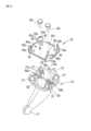
この発明の実施の形態を説明する。図1は、この発明が適用された車両用インナーミラーの実施の形態を示す。図1では、ウインドシールド11に接着された取付ベース12にインナーミラー10を取り付けた状態を、車外からウインドシールド11を透過して見た様子を示す。センサーおよびカバーは外した状態で示す。取付ベース12は、接着面12bを車両のウインドシールド11の車室内側の面に接着して、ウインドシールド11に取り付けられる。したがって、取付ベース12は接着面12bを車両前方斜め上方に向けて傾斜させた姿勢でウインドシールド11に取り付けられている。取付ベース12には、支持ステー14を介してミラー本体16が取り付けられる。ミラー本体16は、反射鏡を使用した旧来のミラーまたは液晶ディスプレイ等の画像表示装置を搭載した電子ミラー(画像表示装置と反射鏡を併設したものを含む)等で構成される。支持ステー14の基端部(すなわち、取付ベース12に取り付けられる側の端部)には、支持ステー取付用板ばね18がねじ止めで取り付けられている。支持ステー14の末端部(すなわち、ミラー本体16が取り付けられる側の端部)には、ミラー本体16がピボット17によりミラー角度を調整可能に取り付けられている。An embodiment of the present invention will be described. FIG. 1 shows an embodiment of a vehicle inner mirror to which the present invention is applied. FIG. 1 shows the state in which an
ウインドシールド11に取付ベース12を取り付けた状態で、支持ステー14は次の手順で取付ベース12に取り付けられる。なお、支持ステー14に対するミラー本体16の取付けは、取付ベース12に対する支持ステー14の取付けを行う前または後に行われる。取付ベース12の支持ステー取付面12a(すなわち、支持ステー14を取り付ける面)と支持ステー14の被取付面14a(すなわち、取付ベース12に取り付けられる面)を対向させる。これにより、支持ステー取付用板ばね18の4本の脚部18aは、取付ベース12に向かう方向に突出する。支持ステー14を取付ベース12に接近させて、支持ステー取付用板ばね18の4本の脚部18aの自由端部を取付ベース12に押し込んで係合させる。これで、取付ベース12と支持ステー14は、支持ステー取付用板ばね18を介して相互に連結される。支持ステー14を回転軸19の周り方向に回転させる。ここで、回転軸19は、対向した支持ステー取付面12aおよび被取付面14aの中心を通り、支持ステー取付面12aおよび被取付面14aに直交する軸である。支持ステー取付面12aと被取付面14aには回転軸19の周り方向に延在する、相互に当接して摺動する当接支持構造20が形成されている。支持ステー取付面12aと被取付面14aは支持ステー取付用板ばね18の付勢力により当接支持構造20で相互に当接する。脚部18aの付勢力に抗して支持ステー14を回転軸19の周りを取付方向(ここでは取付作業者から見て時計回り方向)に回転させると、当接支持構造20により支持ステー取付面12aと被取付面14aの間の距離が拡げられ、これに伴い脚部18aの付勢力が増大する。支持ステー14を所定量回転させたところで、支持ステー14の回転は停止される。これで、支持ステー取付面12aと被取付面14aは、支持ステー取付用板ばね18の付勢力により、当接支持構造20で相互に押圧当接した状態となり、その結果、支持ステー14が取付ベース12に取り付けられた状態となる。インナーミラー10がウインドシールド11に取り付けられた図1の状態で、ミラー本体16に所定量以上の大きな外力が加わると、その外力が支持ステー14を介して取付ベース12に加わり、脚部18aの付勢力に抗して脚部18aと取付ベース12との係合が外れる。その結果、支持ステー14は取付ベース12から脱落する。なお、支持ステー14が取付ベース12から脱落する動作態様には、ミラー本体16に加わる外力の方向に応じて「回転脱落」と「スライド脱落」がある。回転脱落は、支持ステー14が、取付ベース12の支持ステー取付面12aの周方向の任意の1箇所を支点として回転して、取付ベース12から脱落する動作である。すなわち、支持ステー14は、該支点の対角側の箇所が取付ベース12から剥がされるように(すなわち、ウインドシールド11から離れるように)回転して、取付ベース12から脱落する。スライド脱落は、支持ステー14が、取付ベース12の支持ステー取付面12aの傾斜に沿って(すなわち、ウインドシールド11の傾斜に沿って)車両前方斜め下方にスライドして取付ベース12から脱落する動作である。With the mounting
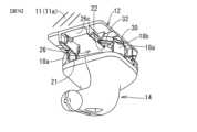
図2は、図1のインナーミラー10を各部品に分解して示す。ミラー本体16の図示は省略する。また、センサーとセンサー組付用板ばねは、両者を組み付けた状態で示す。各部品について説明する。以下の説明では、各部品の回転軸19の周り方向の「上」「下」「左」「右」の各方位を、次の姿勢を基準として表現する。すなわち、該基準姿勢は、インナーミラー10がウインドシールドに取り付けられている状態で、回転軸19を支持ステー14側から取付ベース12側に向かって軸方向に見たときのときの姿勢である。Figure 2 shows the
《取付ベース12》
取付ベース12はガラス繊維強化樹脂、鋼等の材料による一体物で全体が構成されている。取付ベース12の面内には、センサー組付用空所26が形成されている。センサー組付用空所26は、センサー本体収容部26aとコネクタ収容部26bを有する。センサー本体収容部26aは回転軸19を中心とした円形の空所として形成されている。センサー本体収容部26aは、取付ベース12の表裏を貫通して形成されている。コネクタ収容部26bはセンサー本体収容部26aの周方向の一部に連通し、回転軸19を中心に放射方向に延在する矩形の空所として形成されている。コネクタ収容部26bの前端側の左右側壁は連結部26cで相互に連結されている。取付ベース12は、コネクタ収容部26bを上側に配置した姿勢でウインドシールド11の車内側の面(ウインドシールド面)11aに接着で取り付けられる。支持ステー取付面12aには、センサー本体収容部26aに隣接してセンサー本体収容部26aの外周側に、起伏を有する支持面22が形成されている。支持面22は、当接支持構造20の、取付ベース12側の構造を構成する。支持面22は、回転軸19を中心として周方向に延在して形成されている。支持ステー取付面12aの外周面の左右両側位置には、取付ベース側板ばね取付部28が形成されている。取付ベース側板ばね取付部28は、ここでは爪係合用の係合爪として形成されている。支持ステー取付面12aの外周面には、上左、上右、下左、下右の4箇所に、周方向溝30が周方向に延在して形成されている。各周方向溝30の周方向の、反時計回り方向の端部は支持ステー取付面12a側に開口する進入口32にそれぞれ連通している。取付ベース12に支持ステー14を取り付ける際に、進入口32は支持ステー取付用板ばね18の脚部18aの自由端部の爪部18bが回転軸19に沿った方向に移動して進入口32に進入するのを許容する。周方向溝30は進入口32に進入した爪部18bに係合して、爪部18bが回転軸19に沿った方向に移動するのを係止しながら、爪部18bが周方向溝30に沿って回転軸19の周り方向に移動(摺動)するのを許容する。Mounting
The mounting
《センサー34およびセンサー組付用板ばね36》
センサー34は、例えば、所謂レインセンサーまたはレインライトセンサーを樹脂ケース内に配置したセンサーサブアッシーとして構成される。センサー34はセンサー本体34aとコネクタ34bを有する。センサー本体34aにはセンサー素子、基板等が収容される。コネクタ34bには車両側のセンサーハーネス(図示せず)が接続される。センサー本体34aの外周面には、周方向の上左、上右、下左、下右の4箇所にセンサー側板ばね取付部34cが形成されている。センサー側板ばね取付部34cは、ここでは爪係合用の係合爪として形成されている。センサー組付用板ばね36は鋼等の金属材料による1枚の板ばねで構成されている。センサー組付用板ばね36の中央には、センサー34の裏面(非センシング面)34rに対面するセンサー押圧部36cが配置されている。センサー押圧部36cから2本の取付ベース取付用脚部36aと4本のセンサー取付用脚部36bが放射状に配置されている。センサー組付用板ばね36はこのように構成されている。6本の脚部36a,36bの自由端部はセンサー34を包囲するようにウインドシールド11に向かう方向に折り曲げられている。取付ベース取付用脚部36aの自由端部には取付ベース被取付部38がそれぞれ形成されている。センサー取付用脚部36bの自由端部にはセンサー被取付部40がそれぞれ形成されている。取付ベース被取付部38およびセンサー被取付部40は、ここでは爪係合用の爪係合穴としてそれぞれ形成されている。4箇所のセンサー被取付部40を、4箇所のセンサー側板ばね取付部34cにそれぞれ爪係合させることにより、センサー組付用板ばね36はセンサー34に取り付けられる。このとき、センサー組付用板ばね36の付勢力により、センサー押圧部36cがセンサー34の裏面34rに押圧当接するので、センサー組付用板ばね36はセンサー34にがたつきなく取り付けられる。センサー組付用板ばね36がセンサー34に取り付けられた状態で、センサー34を取付ベース12のセンサー組付用空所26に挿入し、センサー組付用板ばね36の左右2箇所の取付ベース被取付部38を取付ベース12の左右2箇所の取付ベース側板ばね取付部28にそれぞれ爪係合させる。これにより、センサー34はセンサー組付用板ばね36を介して取付ベース12に取り付けられる。取付ベース12がウインドシールドに取り付けられた状態では、センサー組付用板ばね36の付勢力により、センサー34のおもて面(センシング面)34fがウインドシールド面11aに押し付けられた状態となる。このようにして、センサー34はセンサー組付用空所26に収容され、かつセンシング面34fがウインドシールド面11aに押し付けられた状態に安定に保持される。<
The
《支持ステー14》
支持ステー14はガラス繊維強化樹脂、鋼等の材料による一体物で全体が構成されている。支持ステー14の被取付面14aには、回転軸19を取り囲んで5本の突出部21が突出形成されている。突出部21は、当接支持構造20の、支持ステー14側の構造を構成する。5本の突出部21の頂部の高さは相互に等しい。つまり、5本の突出部21の頂部は、回転軸19に直交する同一平面上に配置される。<<Support Stay 14>>
The support stay 14 is constructed as a single unit made of a material such as glass fiber reinforced resin or steel. Five
《支持ステー取付用板ばね18》
支持ステー取付用板ばね18は、鋼等の金属材料による1枚の板ばねで構成されている。支持ステー取付用板ばね18の中央には、支持ステー14の被取付面14aに載置支持される支持ステー取付部18cが配置されている。支持ステー取付部18cから4本の脚部18aが放射状に配置されている。支持ステー取付用板ばね18はこのように構成されている。脚部18aは支持ステー取付部18cに対し取付ベース12に向かう方向に折り曲げられている。脚部18aの自由端部は内向きに屈曲されて爪部18bを構成している。全4箇所の爪部18bは、回転軸19に関し相互に同一径方向位置(すなわち、同一円周上)に配置されている。各爪部18bの内周面の周方向エッジ18d,18e(図5B参照)のうち、回転取付方向前端側の周方向エッジ18dはC面に面取りされている。これにより、取付ベース12に支持ステー14を取り付けるために、支持ステー14を回転軸19の周り方向の取付方向に回転させる際に、爪部18bと周方向溝30との摺動抵抗を低減して、取り付けやすくしている。これに対し、回転取付方向後端側の周方向エッジ18eは面取りされていない。これにより、戻り方向(外し方向)について爪部18bと周方向溝30との摺動抵抗を大きくして、車両の振動等により支持ステー14が戻り方向に自然に回転するのを防止している。図2において、支持ステー取付部18cには、4個の突出部挿通穴42、被取付面14aに対する2個の位置決め穴44a,44b、2個のねじ通し穴46が開設されている。4個の突出部挿通穴42は、5本の突出部21のうちの左右4本の突出部21を挿通させる。回転軸19に関し、突出部挿通穴42は脚部18aと同一周方向位置で、脚部18aよりも内周側の位置に形成されている。4個の突出部挿通穴42のうちの1個には、誤組付防止用切欠42a(図4参照)が形成されている。これに対応して、左右4本の突出部21のうちの1個には、誤組付防止用切欠42aを進入させる誤組付防止用リブ21b(図4参照)が形成されている。支持ステー取付用板ばね18の向きを、誤組付防止用リブ21bが誤組付防止用切欠42aに挿入される向きに合わせた状態にして、4本の突出部21を4個の突出部挿通穴42に挿通させて、支持ステー取付用板ばね18を支持ステー14に組み付ける。これにより、支持ステー取付用板ばね18が誤った向きで(すなわち、前後方向に逆向きで)支持ステー14に取り付けられるのが防止される。位置決め穴44aは基準ピン用穴であり、位置決め穴44bは2面幅ピン用穴である。支持ステー取付用板ばね18は2本のタッピングスクリュー48で支持ステー14の被取付面14aに取り付けられる。支持ステー取付用板ばね18が被取付面14aに取り付けられると、5本の突出部21のうちの左右4本の突出部21は脚部18aと同一周方向位置で、脚部18aよりも内周側の位置に配置される。<<Support stay mounting
The support stay mounting
《カバー50および補助カバー52》
カバー50および補助カバー52は樹脂で構成される。カバー50は開口部50aを有する。補助カバー52は開口部52aを有する。カバー50は爪係合で取付ベース12に取り付けられる。カバー50には、この爪係合用の複数の係合爪50bが、開口部50aを臨む位置に形成されている。一方、取付ベース12には、各係合爪50bに係合する爪受け部12dがそれぞれ形成されている。各係合爪50bを各爪受け部12dに爪係合させることにより、カバー50は取付ベース12に取り付けられる。補助カバー52は爪係合でカバー50に取り付けられる。カバー50と補助カバー52により取付ベース12、および取付ベース12と支持ステー14との連結箇所を外部から隠すことができる。カバー50と補助カバー52は取付ベース12、および取付ベース12と支持ステー14との連結箇所を外部から隠すためのものであるので(つまり、これらを隠せればよいので)、小型に構成できる。支持ステー14が大きな外力を受けて取付ベース12から脱落しても、カバー50が取付ベース12に取り付けられた状態は維持される。<<
The
以上説明した各部品を組み付けて、インナーミラー10をウインドシールド11に取り付ける工程を説明する。
《取付ベースに対するセンサーおよびカバーの取付工程》
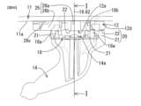
図3は取付ベース12にセンサー34およびカバー50を取り付ける工程を示す。予めウインドシールド面11aに取付ベース12を接着しておく。また、センサー34とセンサー組付用板ばね36を組み付けておく。このように、センサー34とセンサー組付用板ばね36を組み付けておくことにより、後の工程を容易に実行することができる。センサー34をセンサー組付用空所26に挿入して収容する。センサー組付用板ばね36の左右の取付ベース被取付部38(爪係合穴)に取付ベース12の取付ベース側板ばね取付部28(係合爪)を爪係合させてセンサー組付用板ばね36を取付ベース12に取り付ける。これにより、センサー34は取付ベース12に取り付けられる。その結果、センサー組付用板ばね36の付勢力により、センサー34のおもて面すなわちセンシング面34fはウインドシールド面11aに押し付けられる。このように、センサー34は、支持ステー14を取付ベース12に取り付ける前に、ウインドシールド面11aに押し付けられた状態で取付ベース12に安定に保持される。次いで、センサー34のコネクタ34bに車両側のセンサーハーネスのコネクタを接続し、さらにカバー50を爪係合で取付ベース12に取り付ける。カバー50を付け終わったときの状態は図6の上側の図に示されている。 The process of assembling the above-described components and attaching the
<<Step of mounting the sensor and the cover to the mounting base>>
3 shows the process of attaching the
《支持ステーに対する支持ステー取付用板ばねの取付工程》
図4は支持ステー14に支持ステー取付用板ばね18を取り付ける工程を示す。支持ステーの被取付面14aには、4本の突出部21、2本の位置決めピン56a,56b、2個のねじ穴58がそれぞれ形成されている。位置決めピン56aは基準ピン、位置決めピン56bは2面幅ピンである。被取付面14aに支持ステー取付用板ばね18を対面させて、突出部挿通穴42に突出部21を挿入し、位置決め穴44aに基準ピン56aを挿入し、位置決め穴44bに2面幅ピン56bを挿入して、支持ステー取付用板ばね18を支持ステー14の被取付面14aに載置する。次いで、2本のタッピングスクリュー48を2個のねじ通し穴46に差し込んで、ねじ穴58にねじ込む。これで、支持ステー14の被取付面14aに支持ステー取付用板ばね18の支持ステー取付部18cが載置支持された状態で、支持ステー14の被取付面14aに支持ステー取付用板ばね18が取り付けられる。図5Aおよび図5Bはこの被取付面14aへの支持ステー取付用板ばね18の取付けが完了したときの状態をそれぞれ示す。4本の脚部18aは回転軸19を取り囲んで、回転軸19に関し相互に同一径方向位置に配置される。4本の突出部21は回転軸19を取り囲んで、回転軸19に対し、4本の脚部18aと同一周方向位置で、脚部18aよりも内周側の相互に同一径方向位置に配置される。突出部21の頂部は山状の嵌合突起21aを構成している。<<Process for mounting the leaf spring for mounting the support stay to the support stay>>
4 shows the process of attaching the support stay mounting
《取付ベースに対する支持ステーの取付工程》
以上の工程で取付ベース12側および支持ステー14側の部品の組付けが終了したら、取付ベース12に支持ステー14を取り付ける。図6は、取付ベース12に支持ステー14を取り付ける工程を示す。作業者が、支持ステー14を持って、支持ステー14の被取付面14aを取付ベース12の支持ステー取付面12aに対向させる。支持ステー14を回転軸19に沿って取付ベース12に接近する方向に移動させて、4本の脚部18aの爪部18bを進入口32に進入させて押し込んで、爪部18bを周方向溝30に係合させる。これで支持ステー14は取付ベース12に自重で脱落しない程度に緩く連結される。この状態から、支持ステー14を時計回り方向に手で回転させると、爪部18bは周方向溝30に沿って周方向溝30を摺動して移動する。これで、爪部18bは進入口32から外れた位置に来るので、支持ステー14は軽い力では取付ベース12から抜けなくなる。ただし、取付ベース12と支持ステー14の間にはまだがたつきがある。支持ステー14をさらに時計回り方向に回転させると、当接支持構造20により、脚部18aの付勢力に抗して支持ステー取付面12aと被取付面14aの間の距離が拡げられる。ここで、当接支持構造20は支持ステー取付面12aの起伏を有する支持面22と、被取付面14aの被支持面を構成する突出部21とで構成される。これにより、脚部18aの付勢力が増大し、支持面22と突出部21が強く押圧当接する。この状態で支持ステー14の回転が停止され、支持ステー14が取付ベース12に取り付けられた状態となる。このとき、全4箇所の爪部18bは、回転軸19に関し、支持面22と突出部21との当接箇所と同一周方向位置でかつ該当接箇所のすぐ外周側の位置に配置されているので、脚部18aの付勢力を該当接箇所に効率よく伝えて、この取り付けられた状態を安定に保持することができる。支持ステー14が取付ベース12に取り付けられた状態では、支持ステー14はセンサー34およびセンサー組付用板ばね36に非接触である。したがって、取付ベース12に支持ステー14を取り付ける際にセンサー34が正規の位置からずれるのが抑制され、センサー34の組付精度を良好にすることができる。これで、ウインドシールド面11aに対する支持ステー14の取付けが完了する。<<Process for attaching the support stay to the mounting base>>
After the assembly of the components on the mounting
《支持ステーに対するミラー本体の取付工程》
取付ベース12に対する支持ステー14の取付けを行う前または後に、支持ステー14に対するミラー本体16(図1)の取付けを行う。支持ステー14に対するミラー本体16の取付けを行う際には、予め補助カバー52(図2)の開口部52aに支持ステー14に通しておく。支持ステー14に対するミラー本体16の取付けは、支持ステー14のピボット17にミラー本体16を取り付けることにより行われる。補助カバー52は、取付ベース12に支持ステー14が取り付けられた状態で、カバー50に嵌めて取り付けられる。補助カバー52の取付けで全工程が終了する。<<Attachment process of the mirror body to the support stay>>
The mirror body 16 (FIG. 1) is attached to the support stay 14 before or after the
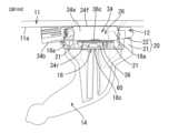
ウインドシールド面11aに対する支持ステー14の取付けが完了した状態における該取付け部分の構造を図7~図10を参照して説明する。なお、図7~図10では、ミラー本体16の図示を省略する。図7A、図7Bは、ウインドシールド面11aに対する支持ステー14の取付けが完了した状態を、センサー34、カバー50、補助カバー52を外してそれぞれ示す。図8A、図8Bは、同状態を、カバー50および補助カバー52を取り付けてそれぞれ示す。図9Aは、同状態を、図9BのII-II矢視位置の断面、すなわち回転軸19を通りかつ車両前後方向に延在する鉛直面64(すなわち、図9Bの紙面に直交する平面)で切断した断面で示す。図9Bは、図9AのI-I矢視位置の断面、すなわち回転軸19を通りかつ車両左右方向に延在する非鉛直面62(すなわち、図9Aの紙面に直交する平面)で切断した断面を示す。図9A、図9Bとも、センサー34、カバー50、補助カバー52を外した状態でそれぞれ示す。図10Aは、図9Aと同じ位置の断面を、センサー34を取り付けて(カバー50、補助カバー52は外して)示す。図10Bは、図9Bと同じ位置の断面を、センサー34を取り付けて(カバー50、補助カバー52は外して)示す。図7A、図7Bに示すように、4本の脚部18aの爪部18bは進入口32から進入して回転軸19の周り方向に回転されて周方向溝30に係合している。また、脚部18aの付勢力により、回転軸19の周り方向の5箇所で、支持面22と、被支持面を構成する突出部21とが強く押圧当接している。これにより、支持ステー14はウインドシールド面11aに安定に取り付けられている。また、図8A、図8Bに示すように、カバー50および補助カバー52を取り付けた状態では、取付ベース12、および取付ベース12と支持ステー14の連結箇所が外部から隠される。また、図10A、図10Bに示すように、センサー34のおもて面(センシング面)34fはセンサー組付用板ばね36によりウインドシールド面11aに押し付けられる。また、支持ステー取付面12aと被取付面14aの間(より正確に言えば、センサー組付用板ばね36のセンサー押圧部36cと支持ステー取付用板ばね18の支持ステー取付部18cの間)に空隙60が形成される。この空隙60を有効利用してセンサーハーネス、カメラモニタリングシステム(CMS)用ハーネス等の各種ハーネス、ハーネスコネクタ等を配設することができる。したがって、これらハーネス、ハーネスコネクタの配置箇所の省スペース化を図ることができるので、ウインドシールド11の前方視界を遮る領域を狭くして、その結果、前方視界を拡げて、安全運転に寄与することができる。また、支持ステー14はセンサー34およびセンサー組付用板ばね36に非接触であるので、車両走行による支持ステー14の振動はセンサー34に伝わり難く、センサー34の故障を生じ難くすることができる。The structure of the mounting portion when the mounting of the support stay 14 to the
前記実施の形態では、当接支持構造の山部、谷部を取付ベース側に配置し、突出部を支持ステー側に配置したが、配置を逆にすることもできる。すなわち、当接支持構造の突出部を支持ステーに配置し、山部、谷部を取付ベース側に配置することができる。前記実施の形態では支持ステーに対する支持ステー取付用板ばねの取付けをねじ止めで行ったが、支持ステーに対する支持ステー取付用板ばねの取付方法はこれに限らない。例えば、支持ステーを樹脂成形するための金型内に支持ステー取付用板ばねを配置して、インサート成形により支持ステーに支持ステー取付用板ばねを取り付けることができる。前記実施の形態のインナーミラーは支持ステーとミラー本体が分割して構成されていたが、この発明は、支持ステーとミラー本体が分割されていない(すなわち、両者が一体構造の)インナーミラーにも適用することができる。In the above embodiment, the peaks and valleys of the abutment support structure are arranged on the mounting base side and the protrusions are arranged on the support stay side, but the arrangement can be reversed. That is, the protrusions of the abutment support structure can be arranged on the support stay and the peaks and valleys can be arranged on the mounting base side. In the above embodiment, the leaf spring for mounting the support stay to the support stay is attached by screwing, but the method of attaching the leaf spring for mounting the support stay to the support stay is not limited to this. For example, the leaf spring for mounting the support stay can be placed in a mold for resin molding the support stay, and the leaf spring for mounting the support stay can be attached to the support stay by insert molding. In the above embodiment, the support stay and the mirror body are configured separately, but this invention can also be applied to an inner mirror in which the support stay and the mirror body are not separated (i.e., both are an integral structure).
10…インナーミラー、11…ウインドシールド、11a…車室内側のウインドシールド面、12…取付ベース、12a…支持ステー取付面、12b…接着面、12d…爪受け部、14…支持ステー、14a…被取付面、16…ミラー本体、17…ピボット、18…支持ステー取付用板ばね、18a…脚部、18b…爪部、18c…支持ステー取付部、18d…爪部の内周面の周方向エッジ(回転取付方向前端側)、18e…爪部の内周面の周方向エッジ(回転取付方向後端側)、19…回転軸、20…当接支持構造、21…突出部、21a…突出部の頂部(嵌合突起)、21b…誤組付防止用リブ、22…支持面、26…センサー組付用空所、26a…センサー本体収容部、26b…コネクタ収容部、26c…連結部、28…取付ベース側板ばね取付部(爪係合用の係合爪)、30…周方向溝、32…進入口、34…センサー、34a…センサー本体、34b…コネクタ、34c…センサー側板ばね取付部(爪係合用の係合爪)、34f…おもて面(センシング面)、34r…裏面(非センシング面)、36…センサー組付用板ばね、36a…取付ベース取付用脚部、36b…センサー取付用脚部、36c…センサー押圧部、38…取付ベース被取付部(爪係合用の爪係合穴)、40…センサー被取付部(爪係合用の爪係合穴)、42…突出部挿通穴、42a…誤組付防止用切欠、44a…位置決め穴(基準ピン用)、44b…位置決め穴(2面幅ピン用)、46…ねじ通し穴、48…タッピングスクリュー、50…カバー、50a…開口部、50b…係合爪、52…補助カバー、52a…開口部、56a…位置決めピン(基準ピン)、56b…位置決めピン(2面幅ピン)、58…ねじ穴、60…空隙、62…回転軸を通りかつ車両左右方向に延在する面、64…回転軸を通りかつ車両前後方向に延在する鉛直面10...inner mirror, 11...windshield, 11a...windshield surface inside the vehicle cabin, 12...mounting base, 12a...support stay mounting surface, 12b...adhesive surface, 12d...claw receiving portion, 14...support stay, 14a...mounted surface, 16...mirror body, 17...pivot, 18...leaf spring for mounting support stay, 18a...leg, 18b...claw portion, 18c...support stay mounting portion, 18d...circumferential edge of inner surface of claw portion (front end side in rotation mounting direction), 18e...claw portion Circumferential edge of the inner peripheral surface (rear end side in the rotation mounting direction), 19...rotating shaft, 20...abutment support structure, 21...projection, 21a...top of projection (fitting protrusion), 21b...rib for preventing incorrect assembly, 22...support surface, 26...void for sensor assembly, 26a...sensor main body accommodating portion, 26b...connector accommodating portion, 26c...connecting portion, 28...mounting base side leaf spring mounting portion (engagement claw for claw engagement), 30...circumferential groove, 32...entrance, 34...sensor, 34a...sensor main body, 34 b...connector, 34c...sensor side leaf spring mounting portion (engagement claw for claw engagement), 34f...front surface (sensing surface), 34r...rear surface (non-sensing surface), 36...sensor assembly leaf spring, 36a...mounting base mounting leg, 36b...sensor mounting leg, 36c...sensor pressing portion, 38...mounting base mounted portion (claw engagement hole for claw engagement), 40...sensor mounted portion (claw engagement hole for claw engagement), 42...projection insertion hole, 42a...notch for preventing incorrect assembly, 44 a...positioning hole (for reference pin), 44b...positioning hole (for two-face width pin), 46...screw through hole, 48...tapping screw, 50...cover, 50a...opening, 50b...engagement claw, 52...auxiliary cover, 52a...opening, 56a...positioning pin (reference pin), 56b...positioning pin (two-face width pin), 58...screw hole, 60...gap, 62...surface passing through the rotation axis and extending in the left-right direction of the vehicle, 64...vertical surface passing through the rotation axis and extending in the front-rear direction of the vehicle
Claims (6)
Translated fromJapanese前記インナーミラーは、車両室内のウインドシールド面に取り付けられる取付ベースと、該取付ベースに脱落可能に取り付けられる支持ステーと、該支持ステーに支持されるミラー本体を有し、
前記インナーミラーは、前記取付ベースの支持ステー取付面と前記支持ステーの被取付面とを対向させて、前記取付ベースと前記支持ステーとを該対向した両面に交差する所定の回転軸の周り方向に相互に回転可能に支持ステー取付用板ばねを介して連結する構造を有し、
前記支持ステー取付面と前記被取付面は、前記回転軸の周り方向に形成されて前記支持ステー取付用板ばねの付勢力により相互に当接する当接支持構造を有し、
前記インナーミラーは、前記取付ベースと前記支持ステーとを前記支持ステー取付用板ばねを介して連結した状態で、前記支持ステーを該支持ステー取付用板ばねの付勢力に抗して前記回転軸の周り方向に回転させたときに、前記当接支持構造により前記支持ステー取付用板ばねの付勢力を増大させて、前記支持ステー取付面と前記被取付面とを相互に押圧当接状態にして、前記支持ステーを前記取付ベースに取り付けるように構成されており、
前記インナーミラーは、前記支持ステーが前記取付ベースに取り付けられた状態で前記支持ステーに所定量以上の外力が加わったときに、前記支持ステー取付用板ばねの付勢力に抗して該外力により、前記支持ステーと前記取付ベースとの連結が外れて前記支持ステーを前記取付ベースから脱落させるように構成されており、
前記組付構造は、前記取付ベースに形成されたセンサー組付用空所と、センサー組付用板ばねと、前記取付ベースに形成された取付ベース側板ばね取付部を有し、
前記センサー組付用空所は前記センサーを収容するように構成され、
前記センサー組付用板ばねは取付ベース被取付部を有し、
前記組付構造は、前記センサーが前記センサー組付用空所に収容された状態で、前記センサー組付用板ばねが前記取付ベース被取付部で前記取付ベース側板ばね取付部に取り付けられ、もって前記センサー組付用板ばねで前記センサーを前記センサー組付用空所に収容された状態に保持するように構成され、
前記支持ステー取付用板ばねは、該支持ステー取付用板ばねの面の中央に位置して前記支持ステーの前記被取付面に取り付けられる支持ステー取付部と、該支持ステー取付部の周縁部における前記回転軸の周り方向の相互に間隔を空けた複数箇所から繋がって前記取付ベースに連結される方向に折り曲げてそれぞれ形成された複数の脚部と、該脚部の自由端部が内向きに屈曲されて構成された爪部を有し、
前記取付ベースは、前記複数の脚部の前記爪部にそれぞれ対応して前記支持ステー取付面の外周面の周方向の複数箇所に該周方向に延在してそれぞれ形成された複数の周方向溝を有し、
前記取付ベースと前記支持ステーとを前記支持ステー取付用板ばねを介して連結する構造は、前記支持ステー取付用板ばねの前記支持ステー取付部を前記支持ステーの前記被取付面に取り付けた状態で、前記周方向溝に前記爪部をそれぞれ係合させて該爪部が前記回転軸に沿った方向に移動するのを係止しながら該爪部が該周方向溝に沿って該回転軸の周り方向に移動するのを許容する構成を有し、
前記取付ベースにおいて、前記取付ベース側板ばね取付部は、前記周方向に隣接する前記周方向溝どうしの間に挟まれた位置であって前記爪部が前記周方向溝に沿った移動によって到達しない該周方向の位置に配置され、該取付ベース側板ばね取付部を挟んで該周方向に隣接する該周方向溝どうしは、該取付ベース側板ばね取付部を挟んで該周方向に隣接する端部どうしがそれぞれ閉じた構成を有している
車両用インナーミラーのセンサー組付構造。 In an assembly structure for assembling a sensor to a vehicle inner mirror,
The inner mirror has an attachment base attached to a windshield surface inside a vehicle cabin, a support stay detachably attached to the attachment base, and a mirror body supported by the support stay,
The inner mirror has a structure in which a support stay mounting surface of the mounting base and a mounted surface of the support stay are opposed to each other, and the mounting base and the support stay are connected via a support stay mounting leaf spring so as to be mutually rotatable in a direction around a predetermined rotation axis intersecting both opposed surfaces,
the support stay mounting surface and the mounted surface have a contact support structure formed in a circumferential direction of the rotation shaft and contacting each other by the biasing force of the support stay mounting leaf spring,
The inner mirror is configured such that, when the support stay is rotated around the rotation axis against the biasing force of the support stay mounting leaf spring in a state in which the mounting base and the support stay are connected via the support stay mounting leaf spring, the biasing force of the support stay mounting leaf spring is increased by the abutment support structure, causing the support stay mounting surface and the mounted surface to be in a pressing abutment state against each other, thereby mounting the support stay to the mounting base,
The inner mirror is configured such that, when an external force of a predetermined amount or more is applied to the support stay with the support stay attached to the mounting base, the external force against the biasing force of the support stay mounting leaf spring causes the connection between the support stay and the mounting base to be released, causing the support stay to fall off the mounting base,
The mounting structure includes a sensor mounting space formed in the mounting base, a sensor mounting leaf spring, and a mounting base side leaf spring mounting portion formed in the mounting base,
the sensor mounting cavity is configured to receive the sensor;
The sensor assembly leaf spring has a mounting base mounting portion,
the assembly structure is configured such that, with the sensor accommodated in the sensor assembly cavity, the sensor assembly leaf spring is attached to the mounting base leaf spring attachment portion at the mounting base attachment portion, thereby the sensor assembly leaf spring holds the sensor accommodated in the sensor assembly cavity;
The support stay mounting leaf spring has a support stay mounting portion located at the center of a surface of the support stay mounting leaf spring and mounted to the mounting surface of the support stay, a plurality of legs formed by connecting a plurality of mutually spaced apart points around the rotation axis on the periphery of the support stay mounting portion and bending the legs in a direction to be connected to the mounting base, and claw portions formed by bending free ends of the legs inwardly,
the mounting base has a plurality of circumferential grooves formed at a plurality of locations in the circumferential direction on the outer peripheral surface of the support stay mounting surface, the circumferential grooves extending in the circumferential direction corresponding to the claw portions of the plurality of legs,
a structure for connecting the mounting base and the support stay via the support stay mounting leaf spring, in a state in which the support stay mounting portion of the support stay mounting leaf spring is mounted to the mounting surface of the support stay, the claw portions are engaged with the circumferential grooves to prevent the claw portions from moving in a direction along the rotation axis while allowing the claw portions to move in a direction around the rotation axis along the circumferential grooves,
In the mounting base, the mounting base side leaf spring mounting portion isdisposed at a circumferential position sandwiched between the circumferential grooves adjacent in the circumferential direction and not reached by the claw portion as it moves along the circumferential groove , and the circumferential grooves adjacent in the circumferential direction across the mounting base side leaf spring mounting portion have a configuration in which adjacent ends in the circumferential direction across the mounting base side leaf spring mounting portion are each closed.
前記組付構造は、前記取付ベースが車両室内のウインドシールド面に取り付けられ、前記センサーが前記センサー組付用空所に収容され、前記センサー組付用板ばねが前記取付ベース被取付部で前記取付ベース側板ばね取付部に取り付けられた状態で、前記センサー押圧部が前記センサーを押圧して、該センサーを前記ウインドシールド面に押し付けるように構成されている
請求項1に記載の車両用インナーミラーのセンサー組付構造。 The sensor assembly leaf spring has a sensor pressing portion,
2. The sensor assembly structure for a vehicle inner mirror as described in claim 1, wherein the assembly structure is configured such that, when the mounting base is attached to a windshield surface inside the vehicle cabin, the sensor is housed in the sensor assembly cavity, and the sensor assembly leaf spring is attached to the mounting base side leaf spring mounting portion at the mounting base mounting portion, the sensor pressing portion presses the sensor to press the sensor against the windshield surface.
前記センサー組付用板ばねはセンサー被取付部を有し、
前記センサー組付用板ばねは前記センサー被取付部で前記センサー側板ばね取付部に取り付けられる
請求項1から3のいずれか1つに記載の車両用インナーミラーのセンサー組付構造。 The assembly structure has a sensor-side leaf spring mounting portion formed on the sensor,
The sensor assembly leaf spring has a sensor mounting portion,
The sensor installation structure for a vehicle inner mirror according to claim 1 , wherein the sensor installation leaf spring is attached to the sensor side leaf spring attachment portion at the sensor attachment portion.
Applications Claiming Priority (3)
| Application Number | Priority Date | Filing Date | Title |
|---|---|---|---|
| JP2018014789 | 2018-01-31 | ||
| JP2018014789 | 2018-01-31 | ||
| PCT/JP2019/002975WO2019151253A1 (en) | 2018-01-31 | 2019-01-29 | Sensor installation structure for rotatable windshield-mounted vehicle inner mirror |
Publications (2)
| Publication Number | Publication Date |
|---|---|
| JPWO2019151253A1 JPWO2019151253A1 (en) | 2021-01-14 |
| JP7549413B2true JP7549413B2 (en) | 2024-09-11 |
Family
ID=67479758
Family Applications (1)
| Application Number | Title | Priority Date | Filing Date |
|---|---|---|---|
| JP2019569137AActiveJP7549413B2 (en) | 2018-01-31 | 2019-01-29 | Sensor assembly structure for a rotating windshield-mounted inner mirror for vehicles |
Country Status (4)
| Country | Link |
|---|---|
| US (1) | US11254264B2 (en) |
| JP (1) | JP7549413B2 (en) |
| CN (1) | CN111712405B (en) |
| WO (1) | WO2019151253A1 (en) |
Families Citing this family (5)
| Publication number | Priority date | Publication date | Assignee | Title |
|---|---|---|---|---|
| WO2018168265A1 (en)* | 2017-03-13 | 2018-09-20 | 株式会社 村上開明堂 | Attachment structure with removal mechanism for on-vehicle device |
| US11731559B2 (en)* | 2018-01-31 | 2023-08-22 | Murakami Corporation | Mounting structure and mounting base for rotary mounting-type windshield mounted in-vehicle device |
| DE102019118217A1 (en)* | 2019-07-05 | 2021-01-07 | HELLA GmbH & Co. KGaA | Housing, in particular for a sensor device |
| DE212021000328U1 (en)* | 2020-03-10 | 2023-01-04 | Gentex Corporation | Bevels for rear sight assembly brackets |
| FR3141407A1 (en)* | 2022-10-28 | 2024-05-03 | Saint-Gobain Glass France | MULTI-MATERIAL PLATE GLAZING, PLATE AND METHOD FOR MANUFACTURING THE GLAZING |
Citations (5)
| Publication number | Priority date | Publication date | Assignee | Title |
|---|---|---|---|---|
| JP2001151019A (en) | 1999-11-25 | 2001-06-05 | Tokai Rika Co Ltd | Vehicle inner mirror device |
| WO2003024745A1 (en) | 2001-09-14 | 2003-03-27 | Murakami Corporation | Vehicle compartment accessory holding device |
| JP2003118486A (en) | 2001-10-11 | 2003-04-23 | Ichikoh Ind Ltd | Inner mirror device for vehicles |
| US20140091123A1 (en) | 2012-09-28 | 2014-04-03 | Gentex Corporation | Double ball slide on mount with screw over sensor |
| US9174577B2 (en) | 2012-08-31 | 2015-11-03 | Gentex Corporation | Mount interface to slide on windscreen button |
Family Cites Families (15)
| Publication number | Priority date | Publication date | Assignee | Title |
|---|---|---|---|---|
| US6326613B1 (en) | 1998-01-07 | 2001-12-04 | Donnelly Corporation | Vehicle interior mirror assembly adapted for containing a rain sensor |
| US6087953A (en)* | 1998-02-18 | 2000-07-11 | Donnelly Corporation | Rearview mirror support incorporating vehicle information display |
| US6250148B1 (en)* | 1998-01-07 | 2001-06-26 | Donnelly Corporation | Rain sensor mount for use in a vehicle |
| US8288711B2 (en)* | 1998-01-07 | 2012-10-16 | Donnelly Corporation | Interior rearview mirror system with forwardly-viewing camera and a control |
| DE29906013U1 (en) | 1999-04-01 | 1999-06-17 | Reitter & Schefenacker GmbH & Co. KG, 73730 Esslingen | Interior rear view mirror for vehicles, in particular for motor vehicles |
| DE10256835B4 (en)* | 2002-12-04 | 2011-03-17 | SMR Patents S.à.r.l. | Interior mirror assembly for a motor vehicle |
| MXPA05008702A (en)* | 2003-02-21 | 2005-10-05 | Gentex Corp | ASSEMBLIES OF AUTOMATIC SYSTEM OF CONTROL OF EXTERNAL LIGHTS OF THE VEHICLE. |
| US7446427B2 (en)* | 2003-05-20 | 2008-11-04 | Gentex Corporation | Rearview mirror system for accommodating a rain sensor |
| JP4713386B2 (en)* | 2006-03-31 | 2011-06-29 | 株式会社村上開明堂 | Car interior accessory holding device |
| DE102007028162A1 (en)* | 2007-06-20 | 2008-12-24 | Dr. Ing. H.C. F. Porsche Aktiengesellschaft | Fastening device for an interior rearview mirror of motor vehicles on an inner side of a windshield |
| US8414137B2 (en) | 2010-10-28 | 2013-04-09 | GM Global Technology Operations LLC | Inside rearview mirror assembly |
| WO2014035958A1 (en)* | 2012-08-27 | 2014-03-06 | Gentex Corporation | Mirror mounting assembly |
| KR101592737B1 (en) | 2014-07-17 | 2016-02-12 | 현대자동차주식회사 | Integrated inside mirror assembly of vehicle |
| DE102015220706A1 (en)* | 2015-10-22 | 2017-04-27 | Magna Mirrors Holding Gmbh | Haltefußanordnung |
| US11731559B2 (en)* | 2018-01-31 | 2023-08-22 | Murakami Corporation | Mounting structure and mounting base for rotary mounting-type windshield mounted in-vehicle device |
- 2019
- 2019-01-29JPJP2019569137Apatent/JP7549413B2/enactiveActive
- 2019-01-29CNCN201980011380.XApatent/CN111712405B/enactiveActive
- 2019-01-29WOPCT/JP2019/002975patent/WO2019151253A1/ennot_activeCeased
- 2019-01-29USUS16/965,166patent/US11254264B2/enactiveActive
Patent Citations (5)
| Publication number | Priority date | Publication date | Assignee | Title |
|---|---|---|---|---|
| JP2001151019A (en) | 1999-11-25 | 2001-06-05 | Tokai Rika Co Ltd | Vehicle inner mirror device |
| WO2003024745A1 (en) | 2001-09-14 | 2003-03-27 | Murakami Corporation | Vehicle compartment accessory holding device |
| JP2003118486A (en) | 2001-10-11 | 2003-04-23 | Ichikoh Ind Ltd | Inner mirror device for vehicles |
| US9174577B2 (en) | 2012-08-31 | 2015-11-03 | Gentex Corporation | Mount interface to slide on windscreen button |
| US20140091123A1 (en) | 2012-09-28 | 2014-04-03 | Gentex Corporation | Double ball slide on mount with screw over sensor |
Also Published As
| Publication number | Publication date |
|---|---|
| US20200361380A1 (en) | 2020-11-19 |
| WO2019151253A1 (en) | 2019-08-08 |
| CN111712405B (en) | 2023-08-29 |
| US11254264B2 (en) | 2022-02-22 |
| CN111712405A (en) | 2020-09-25 |
| JPWO2019151253A1 (en) | 2021-01-14 |
Similar Documents
| Publication | Publication Date | Title |
|---|---|---|
| JP7549413B2 (en) | Sensor assembly structure for a rotating windshield-mounted inner mirror for vehicles | |
| JP7137587B2 (en) | Mounting structure and mounting base for rotating windshield mounting type in-vehicle equipment | |
| JP5947759B2 (en) | Camera unit | |
| KR100898140B1 (en) | Attachment and detachment mechanism for portable electronic device | |
| EP3103684B1 (en) | Camera bracket for a vehicle | |
| JP6592205B2 (en) | In-vehicle electronic device mounting structure | |
| CN101100177B (en) | Attachment structure | |
| KR20010033757A (en) | Anti-theft device for spectacle frames | |
| JP5756139B2 (en) | Imaging device | |
| RU2657610C2 (en) | Vision system for vehicles | |
| CN113825675A (en) | Device for mounting an optical system on a body element of a vehicle | |
| JP6258607B2 (en) | Head-up display device | |
| JP2010195192A (en) | Mounting structure for rotary connector | |
| JP6776500B2 (en) | Camera cover | |
| EP2776284B1 (en) | Fastening device for detector means | |
| JP4509696B2 (en) | Lever switch mounting structure | |
| US12177544B2 (en) | Camera module for vehicles | |
| JP2001039243A (en) | Materials fitting structure to bumper | |
| JP5938066B2 (en) | Vehicle rearview mirror | |
| KR20180065504A (en) | Camera | |
| JP2000003640A (en) | Steering mechanism and method of assembling the same | |
| KR200430380Y1 (en) | Vehicle rear view surveillance camera with angle adjustment | |
| KR20220012242A (en) | vehicle control unit | |
| JP4396844B2 (en) | Steering column cover mounting structure | |
| JP2021102399A (en) | Vehicular camera device |
Legal Events
| Date | Code | Title | Description |
|---|---|---|---|
| A521 | Request for written amendment filed | Free format text:JAPANESE INTERMEDIATE CODE: A821 Effective date:20200723 | |
| A621 | Written request for application examination | Free format text:JAPANESE INTERMEDIATE CODE: A621 Effective date:20211208 | |
| A131 | Notification of reasons for refusal | Free format text:JAPANESE INTERMEDIATE CODE: A131 Effective date:20220823 | |
| A521 | Request for written amendment filed | Free format text:JAPANESE INTERMEDIATE CODE: A523 Effective date:20221021 | |
| A02 | Decision of refusal | Free format text:JAPANESE INTERMEDIATE CODE: A02 Effective date:20230110 | |
| A711 | Notification of change in applicant | Free format text:JAPANESE INTERMEDIATE CODE: A711 Effective date:20230404 | |
| A521 | Request for written amendment filed | Free format text:JAPANESE INTERMEDIATE CODE: A523 Effective date:20230410 | |
| C60 | Trial request (containing other claim documents, opposition documents) | Free format text:JAPANESE INTERMEDIATE CODE: C60 Effective date:20230410 | |
| A521 | Request for written amendment filed | Free format text:JAPANESE INTERMEDIATE CODE: A821 Effective date:20230404 | |
| A911 | Transfer to examiner for re-examination before appeal (zenchi) | Free format text:JAPANESE INTERMEDIATE CODE: A911 Effective date:20230428 | |
| A912 | Re-examination (zenchi) completed and case transferred to appeal board | Free format text:JAPANESE INTERMEDIATE CODE: A912 Effective date:20230519 | |
| A61 | First payment of annual fees (during grant procedure) | Free format text:JAPANESE INTERMEDIATE CODE: A61 Effective date:20240827 | |
| R150 | Certificate of patent or registration of utility model | Ref document number:7549413 Country of ref document:JP Free format text:JAPANESE INTERMEDIATE CODE: R150 |