JP7549313B2 - Short-wavelength radiation source with multi-section collector module - Google Patents
Short-wavelength radiation source with multi-section collector moduleDownload PDFInfo
- Publication number
- JP7549313B2 JP7549313B2JP2023514896AJP2023514896AJP7549313B2JP 7549313 B2JP7549313 B2JP 7549313B2JP 2023514896 AJP2023514896 AJP 2023514896AJP 2023514896 AJP2023514896 AJP 2023514896AJP 7549313 B2JP7549313 B2JP 7549313B2
- Authority
- JP
- Japan
- Prior art keywords
- plasma
- casing
- debris
- radiation
- radiation source
- Prior art date
- Legal status (The legal status is an assumption and is not a legal conclusion. Google has not performed a legal analysis and makes no representation as to the accuracy of the status listed.)
- Active
Links
- 230000005855radiationEffects0.000titleclaimsdescription106
- 230000003287optical effectEffects0.000claimsdescription40
- 230000000116mitigating effectEffects0.000claimsdescription37
- 239000002245particleSubstances0.000claimsdescription25
- OKTJSMMVPCPJKN-UHFFFAOYSA-NCarbonChemical compound[C]OKTJSMMVPCPJKN-UHFFFAOYSA-N0.000claimsdescription19
- 239000002041carbon nanotubeSubstances0.000claimsdescription18
- 229910021393carbon nanotubeInorganic materials0.000claimsdescription18
- 238000000034methodMethods0.000claimsdescription18
- 239000012528membraneSubstances0.000claimsdescription16
- 230000001681protective effectEffects0.000claimsdescription13
- 229910001338liquidmetalInorganic materials0.000claimsdescription7
- 239000011888foilSubstances0.000claimsdescription6
- 229910052751metalInorganic materials0.000claimsdescription6
- 239000002184metalSubstances0.000claimsdescription6
- 239000002238carbon nanotube filmSubstances0.000claimsdescription4
- 230000015572biosynthetic processEffects0.000claimsdescription3
- 210000002381plasmaAnatomy0.000description70
- 239000007789gasSubstances0.000description19
- 239000000463materialSubstances0.000description8
- 150000002500ionsChemical class0.000description6
- 238000010586diagramMethods0.000description4
- 238000007689inspectionMethods0.000description4
- 239000013077target materialSubstances0.000description4
- 230000007423decreaseEffects0.000description3
- 230000006698inductionEffects0.000description3
- 230000007935neutral effectEffects0.000description3
- 239000007787solidSubstances0.000description3
- IJGRMHOSHXDMSA-UHFFFAOYSA-NAtomic nitrogenChemical compoundN#NIJGRMHOSHXDMSA-UHFFFAOYSA-N0.000description2
- 239000006227byproductSubstances0.000description2
- 238000011161developmentMethods0.000description2
- 230000008020evaporationEffects0.000description2
- 238000001704evaporationMethods0.000description2
- 238000001900extreme ultraviolet lithographyMethods0.000description2
- 239000000446fuelSubstances0.000description2
- 230000003993interactionEffects0.000description2
- 238000004519manufacturing processMethods0.000description2
- 150000002739metalsChemical class0.000description2
- 230000001902propagating effectEffects0.000description2
- 230000001960triggered effectEffects0.000description2
- 229910000831SteelInorganic materials0.000description1
- 238000010521absorption reactionMethods0.000description1
- 230000009471actionEffects0.000description1
- 229910045601alloyInorganic materials0.000description1
- 239000000956alloySubstances0.000description1
- QVGXLLKOCUKJST-UHFFFAOYSA-Natomic oxygenChemical compound[O]QVGXLLKOCUKJST-UHFFFAOYSA-N0.000description1
- 229910052797bismuthInorganic materials0.000description1
- 230000000903blocking effectEffects0.000description1
- 229910052799carbonInorganic materials0.000description1
- 230000007547defectEffects0.000description1
- 230000005684electric fieldEffects0.000description1
- 238000002474experimental methodMethods0.000description1
- 239000003574free electronSubstances0.000description1
- 229910052738indiumInorganic materials0.000description1
- 229910052744lithiumInorganic materials0.000description1
- 238000001459lithographyMethods0.000description1
- 230000007774longtermEffects0.000description1
- 230000007246mechanismEffects0.000description1
- 230000008018meltingEffects0.000description1
- 238000002844meltingMethods0.000description1
- 230000005012migrationEffects0.000description1
- 238000013508migrationMethods0.000description1
- 239000002086nanomaterialSubstances0.000description1
- 229910052757nitrogenInorganic materials0.000description1
- 231100000252nontoxicToxicity0.000description1
- 230000003000nontoxic effectEffects0.000description1
- 229910052760oxygenInorganic materials0.000description1
- 239000001301oxygenSubstances0.000description1
- 230000036278prepulseEffects0.000description1
- 238000005086pumpingMethods0.000description1
- 230000003595spectral effectEffects0.000description1
- 239000010959steelSubstances0.000description1
- 239000000126substanceSubstances0.000description1
- 239000000758substrateSubstances0.000description1
- 230000001629suppressionEffects0.000description1
- 238000012360testing methodMethods0.000description1
- 229910052718tinInorganic materials0.000description1
- 229910052724xenonInorganic materials0.000description1
- FHNFHKCVQCLJFQ-UHFFFAOYSA-Nxenon atomChemical compound[Xe]FHNFHKCVQCLJFQ-UHFFFAOYSA-N0.000description1
- 229910052725zincInorganic materials0.000description1
Images


Classifications
- H—ELECTRICITY
- H05—ELECTRIC TECHNIQUES NOT OTHERWISE PROVIDED FOR
- H05G—X-RAY TECHNIQUE
- H05G2/00—Apparatus or processes specially adapted for producing X-rays, not involving X-ray tubes, e.g. involving generation of a plasma
- H05G2/001—Production of X-ray radiation generated from plasma
- H05G2/009—Auxiliary arrangements not involved in the plasma generation
- H05G2/0094—Reduction, prevention or protection from contamination; Cleaning
Landscapes
- Physics & Mathematics (AREA)
- Engineering & Computer Science (AREA)
- Optics & Photonics (AREA)
- Plasma & Fusion (AREA)
- Exposure And Positioning Against Photoresist Photosensitive Materials (AREA)
- X-Ray Techniques (AREA)
- Plasma Technology (AREA)
Description
Translated fromJapaneseこの発明は,約0.4~200nmの波長の軟X線(soft X-ray),超紫外線(EUV)(extreme ultraviolet)および真空紫外(VUV)(vacuum ultraviolet)放射を発生(生成)するように設計された高輝度放射線源および放射線の収集方法に関するもので,これらは大きな集束角(large collection angle)において高効率のデブリ軽減を提供し,高出力光源およびその統合機器の長期運用を保証するものである。The invention relates to a high-brightness radiation source and radiation collection method designed to generate soft X-ray, extreme ultraviolet (EUV) and vacuum ultraviolet (VUV) radiation in the wavelength range of about 0.4-200 nm, which provides efficient debris mitigation at large collection angles and ensures long-term operation of high-power sources and their integrated equipment.
高強度の軟X線,超紫外線(EUV)および真空紫外(VUV)領域の放射線源が,顕微ミラー検査,生物医学的および医学的診断,材料試験,原子物理学におけるナノ構造の解析,ならびにリソグラフィといった多くの分野において使用されている。High-intensity soft x-ray, extreme ultraviolet (EUV) and vacuum ultraviolet (VUV) radiation sources are used in many fields, such as microscopic mirror inspection, biomedical and medical diagnostics, materials testing, analysis of nanostructures in atomic physics, and lithography.
軟X線領域(0.4~10nm),EUV(10~20nm)領域およびVUV(20~120nm)領域において効率的に放出するプラズマは,高出力レーザーの照射をターゲットに集束(集中)させることによっても,放電においても,得ることができる。Plasmas that efficiently emit in the soft x-ray (0.4-10 nm), EUV (10-20 nm) and VUV (20-120 nm) regions can be obtained by focusing (concentrating) high-power laser radiation on a target, as well as by electrical discharge.
2013年8月22日にWO/2014/001071の下で公開された国際特許出願PCT/EP2013/061941から,放射生成プラズマによって生成された放射線を収集し,生成された放射線を案内するための集光器を備え,プラズマ放射線のビームにおける赤外レーザー放射線の抑制手段をさらに備える,集光モジュールを備えたレーザー生成プラズマ(LPP)(laser-produced plasma)EUV光源が知られている。From the international patent application PCT/EP2013/061941 published under WO/2014/001071 on 22 August 2013, a laser-produced plasma (LPP) EUV light source is known, which comprises a collector module, which comprises a collector for collecting radiation produced by the radiation-produced plasma and for guiding the generated radiation, and further comprises means for suppressing infrared laser radiation in the beam of plasma radiation.
LPPEUV光源は高輝度であることを特徴とする。しかしながら,LPPEUV光源の長い寿命を保証するためにデブリから光学集光器を保護する課題がある。LPPEUV light sources are characterized by their high brightness. However, there is a challenge in protecting the optical collector from debris to ensure a long lifetime of the LPPEUV light source.
放射線源の作動中にプラズマの副生成物として発生するデブリは,プラズマ燃料物質の高エネルギーイオン,中性原子または蒸気およびクラスタの形態をとることがある。デブリ粒子は,放射線源の近くに位置する一または複数の集光ミラーから構成し得る集光光学系を劣化させる。集光ミラーに堆積した微液滴および粒子がその反射係数を低下させるという事実に加え,高速粒子が,集光ミラー,および,場合によっては集光ミラーの背後に位置する光学系のその他の部品に損傷を与えることがある。このため,短波長放射線のデブリフリーの高輝度源を開発することが急務である。Debris generated as a by-product of the plasma during the operation of the radiation source can be in the form of energetic ions, neutral atoms or vapors and clusters of plasma fuel material. Debris particles degrade collector optics, which may consist of one or more collector mirrors located close to the radiation source. In addition to the fact that droplets and particles deposited on the collector mirror reduce its reflection coefficient, high-speed particles can damage the collector mirror and possibly other components of the optics located behind it. For this reason, there is an urgent need to develop debris-free high-brightness sources of short-wavelength radiation.
2013年8月22日にWO/2013/122505の下で公開された国際特許出願PCT/RU2012/000701から,レーザートリガー放電プラズマEUV光源が知られている。集光レーザービームは,レーザートリガー放電が非対称で大部分が曲がったバナナ状の形状を有するようにして電極のうちの一つに案内される。そのような放電の固有磁場は,より弱い磁場の領域に対する放電プラズマの支配的な運動を決定する勾配を有する。プラズマ流の方向は光学集光器に向かう方向とは著しく異なっている。高放射力(high radiation power)を得るために上記放電は高パルス繰り返し率(high pulse repetition rate)において生成される。この発明は荷電粒子の簡単かつ高効果的な緩和を提供する。From the international patent application PCT/RU2012/000701, published under WO/2013/122505 on 22 August 2013, a laser-triggered discharge plasma EUV light source is known. A focused laser beam is guided to one of the electrodes in such a way that the laser-triggered discharge has an asymmetric, mostly curved banana-shaped shape. The intrinsic magnetic field of such a discharge has a gradient that determines the predominant motion of the discharge plasma relative to regions of a weaker magnetic field. The direction of the plasma flow is significantly different from the direction towards the optical collector. In order to obtain a high radiation power, the discharge is generated at a high pulse repetition rate. The invention provides a simple and highly effective relaxation of charged particles.
もっとも,中性粒子およびクラスタの抑制にはより高度なデブリ軽減技術の使用が必要である。However, suppression of neutral particles and clusters requires the use of more advanced debris mitigation techniques.
軟X線,EUVおよびVUV領域における発光はレーザー生成プラズマ(laser-produced plasma)の使用によって最も効果的となる。近年のLPP放射線源の開発は,7nmノード以下の集積回路(ICs)の大量生産用の投影極端紫外線リソグラフィの開発によって非常に刺激を受けている。Emission in the soft x-ray, EUV and VUV regions is most effectively achieved through the use of laser-produced plasma. Recent development of LPP radiation sources has been highly stimulated by the development of projection extreme ultraviolet lithography for the mass production of integrated circuits (ICs) at the 7 nm node and below.
特別に注入されたガス中における短波長放射線ビームの経路に沿って生成された補助プラズマの使用に基づくデブリ軽減技術が,2016年2月23日に公開された米国特許第9268031号に開示されている。補助プラズマに触れる(expose)結果として電荷を得るデブリは,その後にパルス電界によって偏向される。この方法は,たとえばキセノンをプラズマ燃料として用いる線源において,デブリのイオン/蒸発部分に対する光学集光器の保護に効果的である。A debris mitigation technique based on the use of an auxiliary plasma generated along the path of a short-wavelength radiation beam in a specially injected gas is disclosed in US Pat. No. 9,268,031, published on Feb. 23, 2016. Debris that acquires an electric charge as a result of exposure to the auxiliary plasma is subsequently deflected by a pulsed electric field. This method is effective for protecting optical collectors against ionized/evaporated debris fractions, for example in sources using xenon as plasma fuel.
しかしながら,金属をプラズマ形成材料として用いる線源において,光学集光器の構成要素に対する主な脅威はデブリ粒子の微液滴部分であり,それに対してこの方法は無力である。However, in sources that use metals as plasma-forming materials, the main threat to the optical collector components is the microdroplet fraction of debris particles, against which this method is ineffective.
2013年8月27日に公開された米国特許第8519366号から,Sn液滴ターゲットを用いるLPPEUV放射線源におけるデブリ軽減方法が知られている。この方法は,デブリ粒子の荷電部分の磁気緩和を用いることを含む。これに加えて,上記デブリ技術は,フォイルトラップおよび保護用のバッファガス流を供給するポートを含み,液体金属ターゲット材の中性原子およびクラスタの十分効果的な閉じ込めを提供する。From US Pat. No. 8,519,366 published on 27 August 2013, a method for debris mitigation in an LPP EUV radiation source using a Sn droplet target is known. The method involves using magnetic relaxation of the charged parts of the debris particles. In addition to this, the debris technique includes a foil trap and a port for supplying a protective buffer gas flow, providing a sufficiently effective confinement of neutral atoms and clusters of the liquid metal target material.
しかしながら,デブリ粒子の微液滴部分を軽減するためにはさらなるかなり複雑な手段が必要である。However, further, rather complex measures are required to mitigate the microdroplet fraction of debris particles.
2007年11月27日に公開された米国特許第7302043号から知られるデブリ軽減方法はこの決定が部分的にない。この方法は高速回転シャッタを利用するもので,このシャッタは1回転周期の間に少なくとも一つの開口を通して短波長放射線を透過させ,シャッタの別の回転周期の間にデブリの通過を阻止することができる。Partly missing this determination is the debris mitigation method known from US Pat. No. 7,302,043 published on 27 November 2007. This method utilizes a rapidly rotating shutter that is capable of transmitting short wavelength radiation through at least one aperture during one rotational period and blocking the passage of debris during another rotational period of the shutter.
しかしながら,小型の放射線源におけるそのようなデブリ軽減手段の使用は,実現するのが技術的にあまりに困難である。However, the use of such debris mitigation measures on small radiation sources is technically too difficult to implement.
この欠点は,それらの全体を参照することによりこの明細書に援用される,2020年4月28日に公開された米国特許第10638588号,2020年3月10日に公開された米国特許第10588210号,2020年5月5日に公開された米国特許出願第20200163197号から知られる短波長放射線源には全くない。これらの特許文献において開示された線源は,集光レーザービームによって相互作用領域に溶融金属層の形でターゲットを到達させる回転ターゲットアセンブリを備える真空チャンバを含む。デブリ軽減手段の複合体は80m/s以上の速い線速度によるターゲットの回転を含む。デブリのイオン/蒸発部分を抑制するために,フォイルトラップ,磁場および保護用バッファガスの指向性流の利用が提供される。放射線源の実施形態では,カーボンナノチューブの交換可能膜(CNT膜)が短波長放射線ビームの経路中に設置される。また,パルス放出プラズマの領域にレーザービームが入射され,そこから短波長放射線ビームを出るようにした,放出プラズマの領域を取り囲むデブリシールドが固定的に設置される。レーザープレパルスを使用してデブリのイオン部分を抑制することも提案されている。別の提案されたデブリ軽減メカニズムは,たとえば,およそ1MHzの高繰り返し率のレーザーパルスを使用するものであり,後続のパルスの放射およびプラズマによって直前のレーザーパルスから生じる最大0.1μmのサイズの微液滴の蒸発を確実にする。This drawback is completely absent in the short-wavelength radiation sources known from U.S. Pat. No. 10,638,588, published on April 28, 2020, U.S. Pat. No. 10,588,210, published on March 10, 2020, and U.S. Patent Application No. 20200163197, published on May 5, 2020, which are incorporated herein by reference in their entirety. The sources disclosed in these patent documents include a vacuum chamber with a rotating target assembly, which delivers a target in the form of a molten metal layer to an interaction region by a focused laser beam. The complex of debris mitigation means includes a rotation of the target with a high linear velocity of 80 m/s or more. To suppress the ion/evaporation portion of the debris, the use of foil traps, magnetic fields and a directional flow of a protective buffer gas is provided. In an embodiment of the radiation source, an exchangeable membrane of carbon nanotubes (CNT membrane) is placed in the path of the short-wavelength radiation beam. Also, a fixed debris shield is provided surrounding the region of the pulsed plasma, into which the laser beam is injected and from which the short-wavelength radiation beam emerges. It has also been proposed to suppress the ionic portion of the debris using laser pre-pulses. Another proposed debris mitigation mechanism uses high repetition rate laser pulses, for example around 1 MHz, to ensure the evaporation of microdroplets with a size of up to 0.1 μm resulting from the previous laser pulse by the emission of the subsequent pulse and the plasma.
これらの方法はデブリ軽減の効率が十分に高いが,それらは短波長プラズマ放射線の集束角を空間的に比較的小さくすることを目的とした結果,短波長放射線ビームの平均出力が多くの用途に不十分であることが分かったものである。Although these methods are quite efficient at mitigating debris, they aim to achieve a relatively small spatial focusing angle of the short-wavelength plasma radiation, and as a result, the average power of the short-wavelength radiation beam has proven insufficient for many applications.
したがって,上述の欠点のうちの少なくともいくつかを排除するニーズがある。特に,小型で,大きな集光角によって非常に強力で,短波長放射線の出力ビームの経路において実質的に完全なデブリ軽減を提供する改善型光源のニーズがある。There is therefore a need to eliminate at least some of the above-mentioned drawbacks. In particular, there is a need for an improved light source that is compact, very powerful with a large collection angle, and provides substantially complete debris mitigation in the path of the output beam of short wavelength radiation.
この発明は,軟X線,EUVおよびVUV放射の純高輝度源の平均出力における多重増加(multiple increase)に関連する技術的課題を解決するとともに,それらの商業利用可能性および経済運用を保証することを目的とする。The invention aims to solve the technical problems associated with multiple increases in the average power of high-brightness net sources of soft X-ray, EUV and VUV radiation, while ensuring their commercial applicability and economic operation.
この発明の技術的結果は,大きな,好ましくは0.25sr以上の立体角において伝播する短波長放射線のビームにおける,高効率のデブリ軽減を伴う非常に強力かつ高輝度の短波長放射線源の作成である。The technical result of this invention is the creation of a very intense and bright source of short-wavelength radiation with highly efficient debris mitigation in a beam of short-wavelength radiation propagating over a large solid angle, preferably 0.25 sr or greater.
上記目的は,集光モジュールを備えたプラズマ短波長放射線源であって,プラズマが短波長放射線を放出する真空チャンバ内に位置する光学集光器を備え,前記光学集光器への前記短波長放射線の経路上のデブリ軽減手段をさらに備えることによって達成可能である。The above objectives can be achieved by a plasma short wavelength radiation source with a collector module, comprising an optical collector located in a vacuum chamber from which the plasma emits short wavelength radiation, and further comprising debris mitigation means on the path of the short wavelength radiation to the optical collector.
前記放射線源は,前記光学集光器に至る(到達する)(coming to)前記短波長放射線のデブリフリーの共心ビーム(debris-free homocentric beams)を出力するように配置された少なくとも2つのケーシングを含み,各ケーシングの外側には,前記ケーシングの内側に磁場を形成する永久磁石があり,前記永久磁石によって形成される磁場が前記共心ビームからデブリ粒子の荷電部分(charged fraction)を除去してデブリフリーの共心ビームを提供する前記デブリ軽減手段によって特徴付けられる。The radiation source is characterized by at least two casings arranged to output debris-free homocentric beams of the short wavelength radiation coming to the optical collector, with a permanent magnet on the outside of each casing forming a magnetic field inside the casing, the magnetic field formed by the permanent magnets removing a charged fraction of debris particles from the homocentric beams to provide a debris-free homocentric beam.
好ましくは,各ケーシングの外面は,前記プラズマからの短波長放射線伝播方向に対して実質的に平行に延在し,かつ垂直方向または別の選ばれた方向に対して平行に延在する2つの第一面(two first faces extended substantially parallel to a direction of short-wavelength radiation propagation from the plasma and parallel to a vertical or to another chosen direction)を含む。Preferably, the outer surface of each casing includes two first faces extended substantially parallel to a direction of short-wavelength radiation propagation from the plasma and parallel to a vertical or to another chosen direction.
好ましくは,各ケーシングは,前記プラズマからの前記短波長放射線伝播方向に実質的に平行に延在し,かつ前記ケーシングの前記2つの第一面に対して実質的に垂直に延在する2つの第二面(two second faces extended substantially parallel to the direction of short-wavelength radiation propagation from the plasma and substantially perpendicular to the two first faces of the casing)を含む。Preferably, each casing includes two second faces extended substantially parallel to the direction of short-wavelength radiation propagation from the plasma and substantially perpendicular to the two first faces of the casing.
この発明の実施形態では,各ケーシングの第一面の面積がケーシングの残りの面の面積よりも大きく,前記永久磁石は各ケーシングの前記第一面と実質的に接触する。In an embodiment of the invention, the area of the first face of each casing is greater than the area of the remaining faces of the casing, and the permanent magnet is in substantial contact with the first face of each casing.
この発明の実施形態では,各ケーシングの前記第一面の面積は前記ケーシングの残りの面の面積未満であり,前記永久磁石は前記ケーシングの前記第一面以外の面に配置されている。In an embodiment of the invention, the area of the first face of each casing is less than the area of the remaining faces of the casing, and the permanent magnets are disposed on faces of the casing other than the first face.
この発明の実施形態では,各ケーシングの前記2つの第一面の間の角度が30度未満である。In an embodiment of the invention, the angle between the two first faces of each casing is less than 30 degrees.
この発明の実施形態では,前記2つの隣り合うケーシングの隣り合う面の間の角度が3~10度である。In an embodiment of the invention, the angle between the adjacent faces of the two adjacent casings is between 3 and 10 degrees.
この発明の実施形態では,互いに最も離れたケーシングの互いに最も離れた部分に配置された前記永久磁石(複数)が磁心によって接続されている。In an embodiment of the invention, the permanent magnets located in the most distant parts of the casings are connected by a magnetic core.
この発明の実施形態では,前記光学集光器が,前記短波長放射線の前記デブリフリーの共心ビームのそれぞれの経路に据え付けられた(installed)複数のミラーを含む。In an embodiment of the invention, the optical collector includes a plurality of mirrors installed in the paths of each of the debris-free concentric beams of the short wavelength radiation.
好ましくは,すべてのミラーの反射面が回転楕円面(spheroid)を形成し,その一つの集中点(in one focus)がプラズマであり,もう一つの集中点(in another focus)が光学集光器のすべてのミラーの焦点(focal point)である。Preferably, the reflective surfaces of all the mirrors form a spheroid, in one focus of which is the plasma and in another focus of which is the focal point of all the mirrors of the optical concentrator.
好ましくは,前記デブリ軽減手段が,短波長放射線のビームの経路(複数)において各ケーシングと前記光学集光器の間に据え付けられたカーボンナノチューブ(CNT)(複数)を主成分(ベース)とする膜(複数)を含む。Preferably, the debris mitigation means includes carbon nanotube (CNT) based membranes mounted between each casing and the optical concentrator in the path of the beam of short wavelength radiation.
この発明の実施形態では,前記デブリ軽減手段は,各ケーシング内において前記プラズマに向かう(directed)保護ガス流(複数)を含み,各CNT膜が,前記短波長放射線の前記デブリフリーの共心ビームの出口用のケーシング窓としての役割と,それを通る前記保護ガスの出口を防ぐガスシャッターとしての役割を同時に果たすものである。In an embodiment of the invention, the debris mitigation means includes protective gas flows within each casing directed toward the plasma, with each CNT film simultaneously acting as a casing window for the exit of the debris-free concentric beam of short wavelength radiation and as a gas shutter preventing the exit of the protective gas therethrough.
この発明の実施形態では,前記永久磁石(複数)が前記ケーシングの全長に沿って配置されている。In this embodiment of the invention, the permanent magnets are arranged along the entire length of the casing.
好ましくは,前記デブリ軽減手段は,前記ケーシングのそれぞれに設置され,前記プラズマに対して径方向で,磁力線(magnetic field lines)に対して実質的に垂直に向けられた(配向された)(oriented)フォイルプレート(複数)を含む。Preferably, the debris mitigation means comprises foil plates mounted in each of the casings and oriented radially with respect to the plasma and substantially perpendicular to the magnetic field lines.
この発明の実施形態では,プラズマは,レーザー生成プラズマ(laser-produced plasma),zピンチプラズマ(z-pinch plasma),プラズマフォーカス(plasma focus),放電生成プラズマ(discharge-produced plasma),レーザー誘導放電生成プラズマ(laser-initiated discharge-produced plasma)からなる群から選択することができる。In an embodiment of the invention, the plasma can be selected from the group consisting of laser-produced plasma, z-pinch plasma, plasma focus, discharge-produced plasma, and laser-initiated discharge-produced plasma.
好ましくは,前記プラズマが,回転ターゲットアセンブリによってレーザービームの焦点領域に供給される液体金属ターゲットのレーザー生成プラズマである。Preferably, the plasma is a laser-produced plasma of a liquid metal target delivered to the focal region of the laser beam by a rotating target assembly.
好ましくは,前記ターゲットが,前記回転ターゲットアセンブリに設けられる,環状溝の回転面の軸に対向する(面する)面上に遠心力によって形成される溶融金属層である。Preferably, the target is a molten metal layer formed by centrifugal force on the surface of the annular groove in the rotating target assembly that faces the axis of rotation.
別の態様においては,この発明は,放射線の収集方法に関するもので,前記方法は,光学集光器によってプラズマ形成位置においてプラズマによって放出される放射線を収集するステップと,前記放射線の少なくとも一部を焦点に案内する(方向づける)(directing)ステップとを含み,前記プラズマによって放出される放射線が,デブリ軽減手段に配備され,短波長放射線のデブリフリーの共心ビームを形成するように配置された少なくとも2つのケーシングを通って外に出て光学集光器に案内される。In another aspect, the invention relates to a method for collecting radiation, the method comprising the steps of collecting radiation emitted by a plasma at a plasma formation location by means of an optical collector and directing at least a portion of the radiation to a focal point, the radiation emitted by the plasma being directed out through at least two casings arranged in a debris mitigation means and arranged to form a debris-free concentric beam of short wavelength radiation to the optical collector.
好ましくは,各ケーシングの外側に,前記ケーシングの内側に磁場を形成する永久磁石があり,前記永久磁石によって形成された磁場はデブリ粒子の荷電部分を軽減し,各ケーシングにおいて保護ガス流,フォイルトラップ,CNT膜を含むその他のデブリ軽減技術も用いて前記デブリフリーの共心ビームを提供する。Preferably, there is a permanent magnet on the outside of each casing which creates a magnetic field on the inside of said casing, the magnetic field created by said permanent magnet mitigates the charged portion of the debris particles, and other debris mitigation techniques including protective gas flow, foil traps, and CNT membranes are also used in each casing to provide said debris-free concentric beam.
好ましくは,前記光学集光器は,前記デブリフリーの共心ビームのそれぞれの前記経路に据え付けられた複数のミラーを含み,すべてのミラーの反射面が楕円面または変形楕円面上にあり,その一つの集中点がプラズマであり,もう一つの集中点が光学集光器のすべてのミラーの焦点である。Preferably, the optical collector includes a plurality of mirrors mounted on the paths of each of the debris-free concentric beams, the reflective surfaces of all mirrors being on an ellipsoid or modified ellipsoid, one of the focal points being the plasma and another focal point being the focal point of all mirrors of the optical collector.
この発明の上述およびその他の目的,効果および特徴は,添付の図面と関連して例示として提供される,その実施形態の以下の非限定的な説明からより明らかとなるであろう。The above and other objects, advantages and features of the present invention will become more apparent from the following non-limiting description of embodiments thereof, provided by way of example in conjunction with the accompanying drawings.
この発明の本質は図面に示されている。The essence of this invention is shown in the drawings.
これらの図面は,この技術的解決策を実施するための選択肢の全範囲を網羅するものでも,さらに,限定するものでもないが,その実施態様の具体的事例の単なる図示資料を表すものである。These drawings do not exhaust or limit the full range of options for implementing this technical solution, but merely represent illustrative material of specific examples of its implementation.
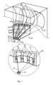
図1にいくつかの縮尺で示す発明実施形態の一例によると,プラズマ放射線源は,短波長放射線を放出するパルス状高温プラズマ2の領域を有する真空チャンバ1を備えている。副生成物として,プラズマ形成材料の蒸気,イオンおよびクラスタを含むデブリ粒子がプラズマ領域に生成される。プラズマ放射線源はさらに,光学集光器3,およびプラズマ2から光学集光器3に案内される短波長放射線ビーム5の経路上に配置されるデブリ軽減手段4とからなる集光モジュールを備えている。光学集光器は,短波長放射線を,中間焦点,そして次に短波長放射線によって動作する光学システムに再案内する。According to an example of an embodiment of the invention shown in several scales in FIG. 1, the plasma radiation source comprises a vacuum chamber 1 having a region of a pulsed
この発明によると,デブリ軽減手段4は,好ましくは複数のミラー8からなる光学集光器3に入る(至る)(coming to)短波長放射線のデブリフリーの共心ビーム7を出力するように配置された少なくとも2つのケーシング6を含む。特徴的なプラズマサイズは約0.1mmであり(自由電子密度のFWHM(半値全幅)または発光プラズマ領域の輝度プロファイルのFWHMとして測定される),したがってプラズマ放射線源は疑似点(quasi-point)とみなすことができ,そこから出てくる放射線ビームは共心(homocentric)とみなすことができる。According to the invention, the debris mitigation means 4 preferably comprises at least two
各ケーシング6の外側には,ケーシング6の内側に磁場を形成する永久磁石9があり,永久磁石9によって形成された磁場は共心ビーム7からデブリ粒子の荷電部分を除去してデブリフリーの共心ビームを提供する。On the outside of each
各ケーシング6の外面は,実質的に前記プラズマ2からの短波長放射線伝播方向に対して平行に,かつ垂直または別の選ばれた方向に対して平行に延在する2つの第一面10を含む。The outer surface of each
各ケーシング6の外側には,ケーシング6の内側に磁場を生成する永久磁石9があり,その磁気誘導ベクトルはケーシングの光軸に対して実質的に垂直に向けられる。On the outside of each
好ましくは,永久磁石9はケーシング6の全長に沿って設けられる。Preferably, the
公知の解決法とは対照的に,この発明によるデブリ軽減手段4はマルチセクション(複数の仕切られた場所の)システム(multi-section system)であり,短波長プラズマ放射線の収集の立体角を大幅に増加させることができるとともに,高効率のデブリ軽減を維持することができる。収集立体角の増加によって短波長放射線の収集力(the collected power of short-wavelength radiation)を大幅に(数倍)増加させることができ,それによってほとんどすべての応用分野においてそのようなタイプの放射線源の使用効率を向上させることができる。In contrast to known solutions, the debris mitigation means 4 according to the invention is a multi-section system, which allows to significantly increase the solid angle of collection of short-wavelength plasma radiation while maintaining a high efficiency of debris mitigation. The increase in the collection solid angle allows to significantly (by several times) increase the collected power of short-wavelength radiation, thereby improving the efficiency of use of such type of radiation source in almost all fields of application.
単一セクションのシステム(single-section system)では,ハウジングの横断寸法の単純な増加が荷電粒子に対する磁気保護の効果の激減を導く。これは,磁場の力線に沿うケーシングの大きさが大きければ大きいほど,ケーシングの容積における磁気誘導の値が低くなるという事実によるもので,これによって短波長3を放出するプラズマの領域から集光ミラー8に向けてケーシングを通って伝播する荷電粒子の横方向速度の減少(a decrease in the transverse velocity of charged particles)につながる。したがって,断面の飛行中,粒子はミラーに衝突するのを回避するために十分な距離を偏向することができない。実験では,磁気保護の有効な動作のためには,短波長を放出するプラズマの領域から約40mmの距離のケーシングの中央における磁気誘導の値が,少なくとも0.5Tであることが必要であることが判明した。また,磁石が配置されるケーシングの側面間の平角(the flat angle between the sides of the casing)は30度を超えてはならないことが実験的に立証された。In single-section systems, a simple increase in the transverse dimensions of the housing leads to a sharp decrease in the effectiveness of the magnetic protection against charged particles. This is due to the fact that the larger the casing is along the field lines of the magnetic field, the lower the value of the magnetic induction in the casing volume, which leads to a decrease in the transverse velocity of charged particles propagating through the casing from the area of the plasma emitting
したがって,ケーシングの面間の平角が30度を超えないマルチセクションのデブリ軽減システムの使用により,各々のケーシングにおいて,荷電粒子の高効果的な磁気緩和に十分な大きさの定磁場を生成することができる。Therefore, the use of a multi-section debris mitigation system in which the flat angle between the faces of the casing does not exceed 30 degrees can generate a constant magnetic field in each casing that is large enough for highly effective magnetic mitigation of charged particles.
この発明の好ましい実施形態によれば,互いに最も離れたケーシング6の互いに最も離れた第一面10に設けられた永久磁石9が磁心11によって接続される。磁心11は,好ましくは磁気的に軟らかい鋼製のもので,磁場を磁心に集中させることによって散乱による磁場の損失を減少させ,それによって各ケーシングの容積における磁場を増加させることができ,磁場デブリ軽減の効率を向上させる。According to a preferred embodiment of the invention, the
この発明の実施形態では,各ケーシング6は,プラズマ2からの短波長放射線伝播方向に対して実質的に平行に延在し,かつケーシングの2つの第一面10に対して実質的に垂直に延在する2つの第二面12を含む。In an embodiment of the invention, each
プラズマ2に対する径方向における第一および第二面10,12の向きによって,幾何学的に透明度が高いマルチセクションのデブリ軽減システム(high geometric transparency of the multisectional debris mitigation)が提供される。この発明の実施形態では,2つの隣り合うケーシング6の隣り合う面の間の角度が3~10度の範囲であるという事実によって,同目的が果たされている。The orientation of the first and
この発明の好ましい実施形態では,各ケーシング6の第一面10の面積はケーシング6の残りの面の面積よりも大きく,永久磁石9は各ケーシング6の第一面10と実質的に接触する。In a preferred embodiment of the invention, the area of the
別の実施形態(図示略)において,各ケーシング6の第一面10の面積はケーシングの残りの面の面積未満であってもよく,永久磁石9はケーシング6の第一面10以外の面,たとえば,各ケーシング6の大きな第二面12に配置してもよい。In another embodiment (not shown), the area of the
デブリ軽減手段4は,好ましくは,共心ビーム7の経路において各ケーシング6と光学集光器3のミラー8の間に据え付けられた(installed)カーボンナノチューブ製の膜13を含む。CNT膜は,好ましくは20~100nmの範囲の厚さを有しており,20nmよりも短い波長の範囲においてそれらの高い強度と高い透明度を保証する。すなわち,CNT膜13は20nmよりも短い波長範囲における高い透明度により共心ビーム7の出口を提供する。同時に,CNT膜13はデブリ粒子の通過を防ぎ,短波長放射線のデブリフリーの共心ビーム7を提供する。The debris mitigation means 4 preferably comprises a
このように,デブリ軽減手段は,各ケーシング6内においてプラズマに向かう保護ガス流を含むとともに,各CNT膜13が,短波長放射線のデブリフリーの共心ビーム7の出口用のケーシング窓と,そこを通って保護ガスが外に出るのを防ぐガスシャッターとしての役割を同時に果たす。The debris mitigation means thus includes a flow of protective gas within each
約20Paの保護ガス圧においてケーシングの平均真空度を提供することによって,プラズマ領域から散乱するガス分子とデブリ粒子との間の衝突数を増加させることができ,それによってそれらを直線運動から偏向させることができる。同時に,ガスシールとしてのCNT膜の使用によって,消費者向け光学機器への共心ビーム7の伝播の全経路に沿うのではなく,ケーシング内のみにおける増加した圧力の使用が可能になる。これはガスへの吸収に起因する短波長放射線の損失を減少させる。By providing an average vacuum in the casing at a protective gas pressure of about 20 Pa, the number of collisions between gas molecules scattering from the plasma region and debris particles can be increased, thereby deflecting them from their linear motion. At the same time, the use of the CNT membrane as a gas seal allows the use of increased pressure only within the casing, rather than along the entire path of propagation of the concentric beam 7 to the consumer optical device. This reduces the loss of short-wavelength radiation due to absorption in the gas.
20nm以上の波長範囲の放射線を得る場合には,その範囲の放射線の透明度が,放射波長が長くなるほどに急激に減少するので,CNT膜13は使用されない。When obtaining radiation in the wavelength range of 20 nm or more, the
図2に示す好ましい実施形態では,光学集光器3は複数のミラー8を含むととも,すべてのミラーの反射面が回転楕円面(ellipsoid of revolution, spheroid)15に属しており(belongs to),その一つの集中点(focus)はパルス放出プラズマ2の領域であり,もう一つの集中点は光学集光器3のミラー8の焦点(the focus point of the mirrors)16である。このようなミラーの製造にはとても費用がかかるが,それは,集光ミラー基板の粗さがほんの0.2~0.3nmであり,特に非球面形状を有するそのようなミラーの費用はそれらのサイズの増加と共に増大し,面積の増加よりも2~3倍強力な法則に従うからである。そのため,複数の同一のミラー8を使用することにより光学集光器の費用が大幅に減少する。In the preferred embodiment shown in FIG. 2, the
パルス放出プラズマは,レーザー生成プラズマ,zピンチプラズマ,プラズマフォーカス,放電生成プラズマ,レーザー誘導放電プラズマからなる群から選択することができる。The pulsed discharge plasma can be selected from the group consisting of laser produced plasma, z-pinch plasma, plasma focus, discharge produced plasma, and laser induced discharge plasma.
好ましい実施形態では,その全体を参照することによりこの明細書に援用される,2020年5月21日に公開された米国特許出願第20200163197号で詳述したように,パルス状高温プラズマは,回転ターゲットアセンブリによってレーザービームの焦点領域に供給される液体金属ターゲット材のレーザープラズマである。In a preferred embodiment, the pulsed high temperature plasma is a laser plasma of a liquid metal target material delivered to the focal region of the laser beam by a rotating target assembly, as detailed in U.S. Patent Application No. 20200163197, published May 21, 2020, which is incorporated herein by reference in its entirety.
図3に概略的に示すこの発明の好ましい実施形態によれば,ターゲット17は,回転軸18に面する回転ターゲットアセンブリ20の環状溝19の表面の遠心力によって形成される溶融金属層である。この発明の好ましい実施形態の等角図を図4に概略的に示す。According to a preferred embodiment of the invention shown diagrammatically in FIG. 3, the
図3および図4に示す液体金属ターゲットのレーザー生成プラズマを用いた好ましい実施形態の高輝度短波長放射線源の操作は次の通りに行われる。真空チャンバ1は,オイルフリーポンプシステムによって10-5・・・10-8mbar以下の圧力までポンピングされ,液体金属ターゲット材と相互に作用することがある窒素,酸素,カーボン等のガス状成分が除去される。 The operation of the preferred embodiment high brightness short wavelength radiation source using a laser produced plasma of a liquid metal target as shown in Figures 3 and 4 is as follows: The vacuum chamber 1 is pumped by an oil-free pumping system to a pressure of up to10-5 ...10-8 mbar to remove gaseous components such as nitrogen, oxygen, carbon, etc. that may interact with the liquid metal target material.
Sn,Li,In,Ga,Pb,Bi,Znおよびそれらの合金を含む非毒性低融点金属の群に属する材料のターゲット17が,回転ターゲットアセンブリによって集光レーザービーム21とともに相互作用領域に供給される。ターゲットは1kHz~1MHzの範囲の高いパルス繰り返し周波数(率,速度)の集光パルスレーザービーム21にさらされる。ターゲット材およびターゲット上のレーザー出力密度に応じて,レーザープラズマの短波長放射線が,軟X線および/またはEUVおよび/またはVUVスペクトル領域において生成される。A
プラズマ2によって放出された短波長放射線のビーム5は,ケーシング6および好ましくはCNT膜13を通過してデブリフリーの共心ビームに変換され,光学集光器3のミラー8に案内される。ここで永久磁石9(図4)が,好ましくは共心ビームの軸に垂直な向きの定磁場(a constant magnetic field, preferably directed perpendicular to the axis of the homocentric beams)を形成する。ローレンツ力の作用の下,共心ビーム7の軸に沿う直線運動から外れたデブリ粒子の荷電部分(主にイオン)が,ケーシング6の内壁またはケーシング内に特別に設置されたプレート22(図3)のいずれかに衝突し,プレートによってトラップされる(閉じ込められる)。ケーシング6内に搭載されたプレート22は,プラズマ2に対して径方向に,好ましくは磁石9によって形成される磁力線に対して垂直に向けられる(directed)。粒子の速度が速ければ速いほど,磁場の影響を受けてそれらが偏向する横断距離が小さくなるので,プレート22によって高速荷電粒子をより効率的に捕捉することができる。これととも,保護ガス流がデブリ粒子のイオン/蒸気部分の移動を防ぎ,それらをケーシング6およびプレート22の壁に堆積させ,デブリからCNT膜13が保護される。20nmよりも短い波長範囲における高い透明度によりCNT膜は光学集光器3のミラー8への短波長ビームの出口を提供する。同時に,CNT膜13はデブリの通過を防ぎ,各ミラー8の信頼性の高い保護を提供する。さらに,ケーシング6内における効果的なデブリ軽減がガス入口14から供給される保護ガスの指向流(流れの向き)(directed flows)を調整することによって保証される。シールドガス流はデブリのイオン/蒸気部分からCNT膜13を保護し,それらの耐用年数を延ばす。The
同様のデブリ軽減手段はレーザービーム21の経路にも沿って使用される。Similar debris mitigation measures are also used along the path of the
上記装置は,その態様の一つにおいて放射線の収集方法に関するこの発明の特定の実施形態を実現する。この方法は,光学集光器3によってプラズマ形成位置においてプラズマ2によって放出される短波長放射線を収集するステップと,放射線の少なくとも一部を焦点16に向けるステップとを含む(図2)。プラズマ2によって放出される放射線ビーム5は,デブリ軽減手段4と一体化され,短波長放射線のデブリフリーの共心ビーム7を形成するように配置された,少なくとも2つのケーシングを通って外に出て光学集光器3に案内される。In one of its aspects, the above device embodies a particular embodiment of the invention with respect to a method for collecting radiation. The method comprises the steps of collecting short-wavelength radiation emitted by the
各ケーシングの外側では,ケーシング6の内側に磁場を形成する永久磁石9がデブリ粒子の荷電部分を軽減するために使用され,保護ガス流,フォイルトラップ,CNT膜を含むその他のデブリ軽減技術もまた各ケーシングにおいて使用され,デブリフリーの共心ビーム7が提供される。On the outside of each casing,
光学集光器3は,好ましくはデブリフリーの共心ビーム7のそれぞれの経路に設けられた複数のミラー8を含み,すべてのミラーの反射面は楕円面15または変形楕円面の表面上にあり,その一つの集中点(焦点)はプラズマ2であり,もう一つの集中点(焦点)16は光学集光器3のすべてのミラー8の焦点である。変形楕円形状を,完全な楕円形状と比較して遠距離場に収集された放射線の強度均一性を向上させるために用いることができる。The
このようにこの発明は,長寿命と使いやすさを備えた,軟X線,EUVおよびVUV放射線のデブリフリーの強力な高輝度線源を形成することを可能にする。The invention thus makes it possible to create powerful, debris-free, high-brightness sources of soft x-ray, EUV and VUV radiation with long lifetime and ease of use.
提案された装置は,多くの分野(顕微ミラー検査,材料科学,材料のX線診断,生物医学的および医学的診断,EUVリソグラフィ用の化学マスク欠陥検査を含むナノおよびマイクロ構造の検査)を適用の対象とする。The proposed device is targeted for many fields of application (microscopic mirror inspection, materials science, X-ray diagnostics of materials, biomedical and medical diagnostics, inspection of nano- and microstructures, including chemical mask defect inspection for EUV lithography).
Claims (18)
Translated fromJapanese前記デブリ軽減手段(4)が,前記光学集光器(3)に至る前記短波長放射線のデブリフリーの共心ビーム(7)を出力するように配置された少なくとも2つのケーシング(6)を含み,
各ケーシングの外面が,前記プラズマ(2)からの短波長放射線伝播方向に対して実質的に平行に延在する2つの第一面(10)を含み,
各ケーシング(6)の外側に,前記ケーシング(6)の内側に磁場を形成する永久磁石(9)があり,前記永久磁石(9)によって形成される磁場が前記共心ビーム(7)からデブリ粒子の荷電部分を除去して前記デブリフリーの共心ビームを提供する,
集光モジュールを備えたプラズマ短波長放射線源。 an optical collector (3) disposed within the vacuum chamber (1) through which the plasma (2) emits short wavelength radiation, and further comprising debris mitigation means (4) on a path of the short wavelength radiation to the optical collector (3);
the debris mitigation means (4) comprising at least two casings (6) arranged to output a debris-free concentric beam (7) of short wavelength radiation leading to the optical collector (3);
The outer surface of each casing includes two first faces (10) extending substantially parallel to the direction of propagation of short-wavelength radiation from the plasma (2);
on the outside of each casing (6) there is a permanent magnet (9) which creates a magnetic field inside said casing (6), the magnetic field created by said permanent magnet (9) removing a charged portion of debris particles from said concentric beam (7) to provide said debris-free concentric beam;
A plasma short-wavelength radiation source with a focusing module.
前記プラズマによって放出される放射線が,デブリ軽減手段に配備され,短波長放射線のデブリフリーの共心ビームを形成するように配置された少なくとも2つのケーシングを通って外へ出て光学集光器に案内され,各ケーシングの外面が,前記プラズマ(2)からの短波長放射線伝播方向に対して実質的に平行に延在する2つの第一面(10)を含み,
各ケーシングの外側で,前記ケーシングの内側に磁場を形成する永久磁石がデブリ粒子の荷電部分を軽減するために使用される,
放射線の収集方法。 collecting radiation emitted by the plasma at a plasma formation location with an optical collector; and guiding at least a portion of the radiation emitted by the plasma to a focal point;
Radiation emitted by the plasma is guided out through at least two casings arranged in the debris mitigation means and arranged to form a debris-free concentric beam of short wavelength radiation to an optical collector, the outer surface of each casingincluding two first faces (10) extending substantially parallel to a direction of propagation of short wavelength radiation from the plasma (2);
On the outside of each casing, permanent magnets are used to create a magnetic field inside said casing in order to reduce the charged portion of the debris particles.
How radiation is collected.
Applications Claiming Priority (5)
| Application Number | Priority Date | Filing Date | Title |
|---|---|---|---|
| RU2020129329ARU2743572C1 (en) | 2020-09-04 | 2020-09-04 | High-brightness source of short-wave radiation (options) |
| RU2020129329 | 2020-09-04 | ||
| US16/952,587US11252810B2 (en) | 2017-11-24 | 2020-11-19 | Short-wavelength radiation source with multisectional collector module and method of collecting radiation |
| US16/952,587 | 2020-11-19 | ||
| PCT/RU2021/050277WO2022050875A1 (en) | 2020-09-04 | 2021-08-26 | Short- wavelength radiation source with multisectional collector module |
Publications (2)
| Publication Number | Publication Date |
|---|---|
| JP2023540119A JP2023540119A (en) | 2023-09-21 |
| JP7549313B2true JP7549313B2 (en) | 2024-09-11 |
Family
ID=80491908
Family Applications (1)
| Application Number | Title | Priority Date | Filing Date |
|---|---|---|---|
| JP2023514896AActiveJP7549313B2 (en) | 2020-09-04 | 2021-08-26 | Short-wavelength radiation source with multi-section collector module |
Country Status (4)
| Country | Link |
|---|---|
| EP (1) | EP4209120A4 (en) |
| JP (1) | JP7549313B2 (en) |
| CN (1) | CN116195369B (en) |
| WO (1) | WO2022050875A1 (en) |
Families Citing this family (2)
| Publication number | Priority date | Publication date | Assignee | Title |
|---|---|---|---|---|
| EP4209120A4 (en)* | 2020-09-04 | 2024-08-28 | Isteq B.V. | SHORT WAVELENGTH RADIATION SOURCE WITH MULTI-SECTION COLLECTOR MODULE |
| US12429783B2 (en)* | 2022-04-11 | 2025-09-30 | Taiwan Semiconductor Manufacturing Company, Ltd. | EUV lithography apparatus and operating method for mitigating contamination |
Citations (5)
| Publication number | Priority date | Publication date | Assignee | Title |
|---|---|---|---|---|
| JP2005522839A (en) | 2002-04-10 | 2005-07-28 | サイマー インコーポレイテッド | Extreme ultraviolet light source |
| JP2008166772A (en) | 2006-12-27 | 2008-07-17 | Asml Netherlands Bv | Debris reduction system and lithographic apparatus |
| JP2009267407A (en) | 2008-04-29 | 2009-11-12 | Asml Netherlands Bv | Radiation source |
| JP2013526071A (en) | 2010-05-06 | 2013-06-20 | カール・ツァイス・エスエムティー・ゲーエムベーハー | EUV collector |
| US20200163197A1 (en) | 2018-08-14 | 2020-05-21 | Isteq B.V. | High brightness laser-produced plasma light source |
Family Cites Families (26)
| Publication number | Priority date | Publication date | Assignee | Title |
|---|---|---|---|---|
| US5763930A (en)* | 1997-05-12 | 1998-06-09 | Cymer, Inc. | Plasma focus high energy photon source |
| TWI299505B (en)* | 2003-04-08 | 2008-08-01 | Cymer Inc | Systems and methods for removal of debris on a reflecting surface of an euv collector in an euv light source |
| WO2005094318A2 (en)* | 2004-03-29 | 2005-10-13 | Jmar Research, Inc. | Morphology and spectroscopy of nanoscale regions using x-rays generated by laser produced plasma |
| US7302043B2 (en)* | 2004-07-27 | 2007-11-27 | Gatan, Inc. | Rotating shutter for laser-produced plasma debris mitigation |
| DE102005015274B4 (en)* | 2005-03-31 | 2012-02-23 | Xtreme Technologies Gmbh | Radiation source for generating short-wave radiation |
| DE102005020521B4 (en)* | 2005-04-29 | 2013-05-02 | Xtreme Technologies Gmbh | Method and device for suppressing debris in the generation of short-wave radiation based on a plasma |
| US8158960B2 (en)* | 2007-07-13 | 2012-04-17 | Cymer, Inc. | Laser produced plasma EUV light source |
| US7687788B2 (en)* | 2007-07-16 | 2010-03-30 | Asml Netherlands B.V. | Debris prevention system, radiation system, and lithographic apparatus |
| US8519366B2 (en)* | 2008-08-06 | 2013-08-27 | Cymer, Inc. | Debris protection system having a magnetic field for an EUV light source |
| NL1036803A (en)* | 2008-09-09 | 2010-03-15 | Asml Netherlands Bv | RADIATION SYSTEM AND LITHOGRAPHIC EQUIPMENT. |
| DE102008049494A1 (en)* | 2008-09-27 | 2010-04-08 | Xtreme Technologies Gmbh | Method and arrangement for operating plasma-based short-wave radiation sources |
| WO2013041323A1 (en)* | 2011-09-22 | 2013-03-28 | Asml Netherlands B.V. | Radiation source |
| DE102013002064A1 (en)* | 2012-02-11 | 2013-08-14 | Media Lario S.R.L. | SOURCE-COLLECTOR MODULES FOR EUV LITHOGRAPHY USING A GIC MIRROR AND AN LPP SOURCE |
| US9268031B2 (en)* | 2012-04-09 | 2016-02-23 | Kla-Tencor Corporation | Advanced debris mitigation of EUV light source |
| US10095119B2 (en)* | 2012-11-15 | 2018-10-09 | Asml Netherlands B.V. | Radiation source and method for lithography |
| US9826615B2 (en)* | 2015-09-22 | 2017-11-21 | Taiwan Semiconductor Manufacturing Co., Ltd. | EUV collector with orientation to avoid contamination |
| RU2658314C1 (en)* | 2016-06-14 | 2018-06-20 | Общество С Ограниченной Ответственностью "Эуф Лабс" | High-frequency source of euf-radiation and method of generation of radiation from laser plasma |
| RU2706713C1 (en)* | 2019-04-26 | 2019-11-20 | Общество С Ограниченной Ответственностью "Эуф Лабс" | High-brightness short-wave radiation source |
| US11252810B2 (en)* | 2017-11-24 | 2022-02-15 | Isteq B.V. | Short-wavelength radiation source with multisectional collector module and method of collecting radiation |
| RU2726316C1 (en)* | 2020-01-25 | 2020-07-13 | Общество С Ограниченной Ответственностью "Эуф Лабс" | High-brightness source of short-wave radiation based on laser plasma |
| RU2670273C2 (en)* | 2017-11-24 | 2018-10-22 | Общество с ограниченной ответственностью "РнД-ИСАН" | Device and method for emission generation from laser plasma |
| US12028958B2 (en)* | 2017-11-24 | 2024-07-02 | Isteq B.V. | High-brightness laser produced plasma source and method of generation and collection radiation |
| CN111399346A (en)* | 2020-04-14 | 2020-07-10 | 中国科学院上海光学精密机械研究所 | LPP-EUV light source system based on plasma confinement |
| EP4209120A4 (en)* | 2020-09-04 | 2024-08-28 | Isteq B.V. | SHORT WAVELENGTH RADIATION SOURCE WITH MULTI-SECTION COLLECTOR MODULE |
| KR102802111B1 (en)* | 2020-11-19 | 2025-05-02 | 아이에스티이큐 비.브이. | Shortwave radiation source with multi-section collector module |
| KR20240087651A (en)* | 2021-11-03 | 2024-06-19 | 아이에스티이큐 비.브이. | High-brightness laser-generated plasma source and radiation generation and collection method |
- 2021
- 2021-08-26EPEP21864799.8Apatent/EP4209120A4/enactivePending
- 2021-08-26JPJP2023514896Apatent/JP7549313B2/enactiveActive
- 2021-08-26WOPCT/RU2021/050277patent/WO2022050875A1/ennot_activeCeased
- 2021-08-26CNCN202180054712.XApatent/CN116195369B/enactiveActive
Patent Citations (5)
| Publication number | Priority date | Publication date | Assignee | Title |
|---|---|---|---|---|
| JP2005522839A (en) | 2002-04-10 | 2005-07-28 | サイマー インコーポレイテッド | Extreme ultraviolet light source |
| JP2008166772A (en) | 2006-12-27 | 2008-07-17 | Asml Netherlands Bv | Debris reduction system and lithographic apparatus |
| JP2009267407A (en) | 2008-04-29 | 2009-11-12 | Asml Netherlands Bv | Radiation source |
| JP2013526071A (en) | 2010-05-06 | 2013-06-20 | カール・ツァイス・エスエムティー・ゲーエムベーハー | EUV collector |
| US20200163197A1 (en) | 2018-08-14 | 2020-05-21 | Isteq B.V. | High brightness laser-produced plasma light source |
Also Published As
| Publication number | Publication date |
|---|---|
| CN116195369B (en) | 2024-10-18 |
| WO2022050875A1 (en) | 2022-03-10 |
| CN116195369A (en) | 2023-05-30 |
| JP2023540119A (en) | 2023-09-21 |
| EP4209120A4 (en) | 2024-08-28 |
| EP4209120A1 (en) | 2023-07-12 |
Similar Documents
| Publication | Publication Date | Title |
|---|---|---|
| KR102649379B1 (en) | Plasma light source generated by high-intensity laser | |
| JP6860185B2 (en) | High-intensity LPP radiation source, radiation generation method, and debris reduction method | |
| US8003963B2 (en) | Extreme ultraviolet light source apparatus | |
| US8129700B2 (en) | Optical element contamination preventing method and optical element contamination preventing device of extreme ultraviolet light source | |
| US8519366B2 (en) | Debris protection system having a magnetic field for an EUV light source | |
| KR102298600B1 (en) | Apparatus and methods for optics protection from debris in plasma-based light source | |
| US11252810B2 (en) | Short-wavelength radiation source with multisectional collector module and method of collecting radiation | |
| JP7549313B2 (en) | Short-wavelength radiation source with multi-section collector module | |
| JP7682505B2 (en) | Target material, high brightness EUV source and method for producing EUV radiation | |
| JP2024540157A (en) | High-intensity laser-produced plasma source and method for generating and collecting radiation | |
| RU2743572C1 (en) | High-brightness source of short-wave radiation (options) | |
| US12028958B2 (en) | High-brightness laser produced plasma source and method of generation and collection radiation | |
| KR102802111B1 (en) | Shortwave radiation source with multi-section collector module | |
| RU2726316C1 (en) | High-brightness source of short-wave radiation based on laser plasma | |
| RU2789275C1 (en) | Target material, high-brightness euv source and 13.5 nm radiation generation method | |
| RU2776025C1 (en) | High-brightness source based on laser plasma and method of generation and collection of radiation | |
| HK40060058A (en) | High brightness laser-produced plasma light source | |
| Fornaciari et al. | Discharge source with gas curtain for protecting optics from particles |
Legal Events
| Date | Code | Title | Description |
|---|---|---|---|
| A521 | Request for written amendment filed | Free format text:JAPANESE INTERMEDIATE CODE: A523 Effective date:20230411 | |
| A621 | Written request for application examination | Free format text:JAPANESE INTERMEDIATE CODE: A621 Effective date:20230411 | |
| A977 | Report on retrieval | Free format text:JAPANESE INTERMEDIATE CODE: A971007 Effective date:20240206 | |
| A131 | Notification of reasons for refusal | Free format text:JAPANESE INTERMEDIATE CODE: A131 Effective date:20240220 | |
| A521 | Request for written amendment filed | Free format text:JAPANESE INTERMEDIATE CODE: A523 Effective date:20240502 | |
| TRDD | Decision of grant or rejection written | ||
| A01 | Written decision to grant a patent or to grant a registration (utility model) | Free format text:JAPANESE INTERMEDIATE CODE: A01 Effective date:20240723 | |
| A61 | First payment of annual fees (during grant procedure) | Free format text:JAPANESE INTERMEDIATE CODE: A61 Effective date:20240821 | |
| R150 | Certificate of patent or registration of utility model | Ref document number:7549313 Country of ref document:JP Free format text:JAPANESE INTERMEDIATE CODE: R150 |