JP7547553B2 - Training Method - Google Patents
Training MethodDownload PDFInfo
- Publication number
- JP7547553B2 JP7547553B2JP2023078503AJP2023078503AJP7547553B2JP 7547553 B2JP7547553 B2JP 7547553B2JP 2023078503 AJP2023078503 AJP 2023078503AJP 2023078503 AJP2023078503 AJP 2023078503AJP 7547553 B2JP7547553 B2JP 7547553B2
- Authority
- JP
- Japan
- Prior art keywords
- flow path
- liquid
- branch
- branch flow
- training method
- Prior art date
- Legal status (The legal status is an assumption and is not a legal conclusion. Google has not performed a legal analysis and makes no representation as to the accuracy of the status listed.)
- Active
Links
- 238000000034methodMethods0.000titleclaimsdescription102
- 238000012549trainingMethods0.000titleclaimsdescription44
- 239000007788liquidSubstances0.000claimsdescription195
- 206010028980NeoplasmDiseases0.000claimsdescription64
- 238000004088simulationMethods0.000claimsdescription46
- 239000003814drugSubstances0.000claimsdescription36
- 229940124597therapeutic agentDrugs0.000claimsdescription35
- 238000003780insertionMethods0.000claimsdescription23
- 230000037431insertionEffects0.000claimsdescription23
- 238000011144upstream manufacturingMethods0.000claimsdescription20
- 239000008280bloodSubstances0.000claimsdescription6
- 210000004369bloodAnatomy0.000claimsdescription6
- 206010069729Collateral circulationDiseases0.000claimsdescription2
- XLYOFNOQVPJJNP-UHFFFAOYSA-NwaterSubstancesOXLYOFNOQVPJJNP-UHFFFAOYSA-N0.000description170
- 238000013334tissue modelMethods0.000description71
- 230000003073embolic effectEffects0.000description30
- 210000001519tissueAnatomy0.000description24
- 239000003795chemical substances by applicationSubstances0.000description23
- 210000004204blood vesselAnatomy0.000description22
- 238000010586diagramMethods0.000description11
- 210000005228liver tissueAnatomy0.000description11
- 238000002347injectionMethods0.000description9
- 239000007924injectionSubstances0.000description9
- 230000017531blood circulationEffects0.000description8
- 201000011510cancerDiseases0.000description6
- 230000008859changeEffects0.000description6
- 239000012780transparent materialSubstances0.000description5
- 238000011282treatmentMethods0.000description5
- 239000002872contrast mediaSubstances0.000description4
- 238000009825accumulationMethods0.000description3
- 230000000903blocking effectEffects0.000description3
- 210000004027cellAnatomy0.000description3
- 230000010109chemoembolizationEffects0.000description3
- 230000010102embolizationEffects0.000description3
- 230000003278mimic effectEffects0.000description3
- 239000000126substanceSubstances0.000description3
- PEDCQBHIVMGVHV-UHFFFAOYSA-NGlycerineChemical compoundOCC(O)COPEDCQBHIVMGVHV-UHFFFAOYSA-N0.000description2
- 238000002583angiographyMethods0.000description2
- 239000002246antineoplastic agentSubstances0.000description2
- 210000001367arteryAnatomy0.000description2
- 239000012530fluidSubstances0.000description2
- 239000000463materialSubstances0.000description2
- 239000004417polycarbonateSubstances0.000description2
- 239000011148porous materialSubstances0.000description2
- 230000008569processEffects0.000description2
- 229920005989resinPolymers0.000description2
- 239000011347resinSubstances0.000description2
- 229910052710siliconInorganic materials0.000description2
- 239000010703siliconSubstances0.000description2
- 239000007787solidSubstances0.000description2
- 230000001225therapeutic effectEffects0.000description2
- 239000004925Acrylic resinSubstances0.000description1
- 229920000178Acrylic resinPolymers0.000description1
- FBPFZTCFMRRESA-KVTDHHQDSA-ND-MannitolChemical compoundOC[C@@H](O)[C@@H](O)[C@H](O)[C@H](O)COFBPFZTCFMRRESA-KVTDHHQDSA-N0.000description1
- LFQSCWFLJHTTHZ-UHFFFAOYSA-NEthanolChemical compoundCCOLFQSCWFLJHTTHZ-UHFFFAOYSA-N0.000description1
- 108010010803GelatinProteins0.000description1
- 229930195725MannitolNatural products0.000description1
- 229920012266Poly(ether sulfone) PESPolymers0.000description1
- 239000004698PolyethyleneSubstances0.000description1
- 206010060862Prostate cancerDiseases0.000description1
- 208000000236Prostatic NeoplasmsDiseases0.000description1
- 206010046798Uterine leiomyomaDiseases0.000description1
- 230000009471actionEffects0.000description1
- 239000003242anti bacterial agentSubstances0.000description1
- 229940041181antineoplastic drugDrugs0.000description1
- 230000015572biosynthetic processEffects0.000description1
- 230000036772blood pressureEffects0.000description1
- 238000004891communicationMethods0.000description1
- 239000000032diagnostic agentSubstances0.000description1
- 229940039227diagnostic agentDrugs0.000description1
- 229940079593drugDrugs0.000description1
- 230000002526effect on cardiovascular systemEffects0.000description1
- 230000000694effectsEffects0.000description1
- 229920001971elastomerPolymers0.000description1
- 239000000839emulsionSubstances0.000description1
- 238000005516engineering processMethods0.000description1
- 229920000159gelatinPolymers0.000description1
- 239000008273gelatinSubstances0.000description1
- 235000019322gelatineNutrition0.000description1
- 235000011852gelatine dessertsNutrition0.000description1
- 235000011187glycerolNutrition0.000description1
- 206010073071hepatocellular carcinomaDiseases0.000description1
- 231100000844hepatocellular carcinomaToxicity0.000description1
- 201000010260leiomyomaDiseases0.000description1
- 210000004185liverAnatomy0.000description1
- 201000007270liver cancerDiseases0.000description1
- 208000014018liver neoplasmDiseases0.000description1
- 230000007774longtermEffects0.000description1
- 235000010355mannitolNutrition0.000description1
- 239000000594mannitolSubstances0.000description1
- 238000005259measurementMethods0.000description1
- 239000012528membraneSubstances0.000description1
- 210000004088microvesselAnatomy0.000description1
- 239000000203mixtureSubstances0.000description1
- 238000012986modificationMethods0.000description1
- 230000004048modificationEffects0.000description1
- NJPPVKZQTLUDBO-UHFFFAOYSA-NnovaluronChemical compoundC1=C(Cl)C(OC(F)(F)C(OC(F)(F)F)F)=CC=C1NC(=O)NC(=O)C1=C(F)C=CC=C1FNJPPVKZQTLUDBO-UHFFFAOYSA-N0.000description1
- 230000008520organizationEffects0.000description1
- 239000000049pigmentSubstances0.000description1
- 239000004033plasticSubstances0.000description1
- 229920003023plasticPolymers0.000description1
- 229920000515polycarbonatePolymers0.000description1
- -1polyethylenePolymers0.000description1
- 229920000573polyethylenePolymers0.000description1
- 229920002635polyurethanePolymers0.000description1
- 239000004814polyurethaneSubstances0.000description1
- 239000003755preservative agentSubstances0.000description1
- 230000002335preservative effectEffects0.000description1
- 229920002050silicone resinPolymers0.000description1
- 239000007779soft materialSubstances0.000description1
- 238000001356surgical procedureMethods0.000description1
- 238000002560therapeutic procedureMethods0.000description1
- 210000004881tumor cellAnatomy0.000description1
- 230000002792vascularEffects0.000description1
Images


Classifications
- G—PHYSICS
- G09—EDUCATION; CRYPTOGRAPHY; DISPLAY; ADVERTISING; SEALS
- G09B—EDUCATIONAL OR DEMONSTRATION APPLIANCES; APPLIANCES FOR TEACHING, OR COMMUNICATING WITH, THE BLIND, DEAF OR MUTE; MODELS; PLANETARIA; GLOBES; MAPS; DIAGRAMS
- G09B23/00—Models for scientific, medical, or mathematical purposes, e.g. full-sized devices for demonstration purposes
- G09B23/28—Models for scientific, medical, or mathematical purposes, e.g. full-sized devices for demonstration purposes for medicine
- G09B23/285—Models for scientific, medical, or mathematical purposes, e.g. full-sized devices for demonstration purposes for medicine for injections, endoscopy, bronchoscopy, sigmoidscopy, insertion of contraceptive devices or enemas
- G—PHYSICS
- G09—EDUCATION; CRYPTOGRAPHY; DISPLAY; ADVERTISING; SEALS
- G09B—EDUCATIONAL OR DEMONSTRATION APPLIANCES; APPLIANCES FOR TEACHING, OR COMMUNICATING WITH, THE BLIND, DEAF OR MUTE; MODELS; PLANETARIA; GLOBES; MAPS; DIAGRAMS
- G09B23/00—Models for scientific, medical, or mathematical purposes, e.g. full-sized devices for demonstration purposes
- G09B23/28—Models for scientific, medical, or mathematical purposes, e.g. full-sized devices for demonstration purposes for medicine
- G09B23/30—Anatomical models
- G09B23/303—Anatomical models specially adapted to simulate circulation of bodily fluids
Landscapes
- Engineering & Computer Science (AREA)
- Physics & Mathematics (AREA)
- General Physics & Mathematics (AREA)
- Health & Medical Sciences (AREA)
- Mathematical Physics (AREA)
- Educational Administration (AREA)
- Medical Informatics (AREA)
- Algebra (AREA)
- Computational Mathematics (AREA)
- General Health & Medical Sciences (AREA)
- Mathematical Analysis (AREA)
- Mathematical Optimization (AREA)
- Chemical & Material Sciences (AREA)
- Pure & Applied Mathematics (AREA)
- Business, Economics & Management (AREA)
- Medicinal Chemistry (AREA)
- Educational Technology (AREA)
- Theoretical Computer Science (AREA)
- Pulmonology (AREA)
- Radiology & Medical Imaging (AREA)
- Instructional Devices (AREA)
- Media Introduction/Drainage Providing Device (AREA)
- Gyroscopes (AREA)
- Amplifiers (AREA)
- Control Of Motors That Do Not Use Commutators (AREA)
- Infusion, Injection, And Reservoir Apparatuses (AREA)
Description
Translated fromJapanese本発明は、トレーニング方法に関する。すなわち、カテーテルを用いて治療する際の、生体の癌や腫瘍の血流状態を再現することができ、さらには手術の効果や原理等を学ぶことのできる手技シミュレータを用いたカテーテル手技のトレーニング方法に関する。The present invention relates to a training method, that is, a catheterization procedure training method using a procedure simulator that can reproduce the blood flow state of cancer or tumor in a living body when treating with a catheter, and further, can teach the effects and principles of surgery, etc.
肝臓癌や、前立腺癌、子宮筋腫等に対して、動脈内に挿入したカテーテルを通じて造影剤等の診断剤や、抗癌剤や塞栓物質等の治療剤を投与し、診断・治療する技術が知られている。これらの治療は、癌や腫瘍等の治療対象組織に選択的に治療剤を投与するとともに、正常組織にはできる限り治療剤が流れないようにすることが望ましい。There is a known technique for diagnosing and treating liver cancer, prostate cancer, uterine fibroids, etc., by administering diagnostic agents such as contrast agents, or therapeutic agents such as anticancer agents and embolic substances through a catheter inserted into an artery. In these treatments, it is desirable to selectively administer the therapeutic agent to the target tissue such as cancer or tumor, while preventing the therapeutic agent from flowing into normal tissue as much as possible.
近年、癌組織には微小な動脈血管が過剰形成されることで、動脈流が集中し得ることに着目し、この現象を利用したB-TACE(Balloon occluded Trans Arterial Chemo Embolization)等と呼ばれる手技が、例えば、以下の文献で報告されている。In recent years, attention has been focused on the fact that arterial flow can become concentrated due to the excessive formation of tiny arterial blood vessels in cancer tissue, and a procedure called B-TACE (Balloon occluded Trans Arterial Chemo Embolization) that utilizes this phenomenon has been reported in the following literature, for example.
入江、他2名(Irie et al.)、「選択的バルーン閉塞動脈塞栓術中の肝細胞癌結節におけるリピオドールエマルジョンの高密度集積:バルーン閉塞動脈圧の測定(Dense Accumulation of Lipiodol Emulsion in Hepatocellular Carcinoma Nodule during Selective Balloon-occluded Transarterial Chemoembolization: Measurement of Balloon-occluded Arterial Stump Pressure)」、カーディオバスキュラー・アンド・インターベンション・ラジオロジー(Cardio Vascular and Intervention Radiology)、2013年、36号、p.706-713Irie et al., "Dense Accumulation of Lipiodol Emulsion in Hepatocellular Carcinoma Nodule during Selective Balloon-occluded Transarterial Chemoembolization: Measurement of Balloon-occluded Arterial Stump Pressure," Cardio Vascular and Intervention Radiology, 2013, No. 36, pp. 706-713.
松本、他9名(Matsumoto et al.)、「バルーン閉塞した動脈の化学塞栓術前のバルーン閉塞動脈圧(Balloon-occluded arterial stump pressure before balloon-occluded transarterial chemoembolization)」、ミニマリ・インベイシブ・セラピー・アンド・アライド・テクノロジーズ(Minimally Invasive Therapy & Allied Technologies)、2015年9月25日、インターネット〈URL:http://www.tandfonline.com/action/journalInformation?journalCode=imit20〉Matsumoto et al., "Balloon-occluded arterial stump pressure before balloon-occluded transarterial chemoembolization," Minimally Invasive Therapy & Allied Technologies, September 25, 2015, Internet <URL: http://www.tandfonline.com/action/journalInformation?journalCode=imit20>
米国特許第9844383号明細書U.S. Patent No. 9,844,383
B-TACEは、カテーテル先端部のバルーンで治療対象組織より上流の動脈を閉塞した状態で治療剤を投与することで、正常組織と治療対象組織との間で局所的な血圧の較差(圧較差)を生じさせ、治療剤を血流に乗って移動させることにより治療対象部位に特異的に治療剤を集中させる手法である。B-TACE is a technique in which a therapeutic agent is administered while the artery upstream of the target tissue is blocked with a balloon at the tip of the catheter, creating a localized difference in blood pressure (pressure gradient) between normal tissue and the target tissue, and the therapeutic agent travels through the bloodstream, concentrating the agent specifically at the target site.
しかしながら、従来の治療に慣れている医師にとって、生体内で局所的に発生するこのような現象を直感的に理解することは難しく、これらの手技が医療現場で普及しているとは言い難いのが実情である。However, for doctors accustomed to conventional treatments, it is difficult to intuitively understand these phenomena that occur locally within the body, and the reality is that these techniques are not yet widespread in the medical field.
そのため、バルーンで血管を閉塞することによって圧較差が生じ、特定部位に選択的に治療剤を投与することが可能であることを体感できる手技シミュレータを用いたトレーニング方法が求められている。Therefore, there is a demand for a training method that uses a procedural simulator that allows trainees to experience how a pressure gradient is created by blocking a blood vessel with a balloon, making it possible to selectively administer a therapeutic agent to a specific area.
以下の開示の一態様は、血液を模した液体を内包する流路と、前記液体に流れを付与する液流発生部材と、前記流路内にカテーテルを介入させるカテーテル挿入ポートと、を備え、前記流路は、前記カテーテル挿入ポートよりも下流に設けられるとともに少なくとも2つの流路に分岐する分岐部と、前記分岐部の下流に設けられた複数の分岐流路とを有し、前記複数の分岐流路は、第1の分岐流路と第2の分岐流路とを有し、さらに、前記第1の分岐流路の下流側と前記第2の分岐流路の下流側との間に圧較差を発生させる圧較差発生部材を備え、前記液流発生部材は、前記第1の分岐流路の下流側と前記第2の分岐流路の下流側とに付与される圧力よりも高い圧力を発生する、手技シミュレータを用いたカテーテル手技のトレーニング方法であって、前記カテーテル挿入ポートから前記カテーテルを挿入し、前記カテーテルの先端を前記分岐部よりも下流側に進めるステップと、前記カテーテルの末端開口から模擬治療剤を投与するステップと、を有する、トレーニング方法である。The following disclosure is an embodiment of a catheter procedure training method using a procedure simulator, comprising: a flow path containing a liquid simulating blood; a liquid flow generating member that imparts a flow to the liquid; and a catheter insertion port for inserting a catheter into the flow path, the flow path having a branching section that is provided downstream of the catheter insertion port and branches into at least two flow paths; and a plurality of branched flow paths provided downstream of the branching section, the plurality of branched flow paths having a first branching flow path and a second branching flow path; and a pressure gradient generating member that generates a pressure gradient between the downstream side of the first branching flow path and the downstream side of the second branching flow path, the liquid flow generating member generating a pressure higher than the pressure applied to the downstream side of the first branching flow path and the downstream side of the second branching flow path, the training method comprising the steps of inserting the catheter through the catheter insertion port, advancing the tip of the catheter downstream of the branching section, and administering a simulated therapeutic agent through the end opening of the catheter.
上記態様のトレーニング方法によれば、カテーテルにより分岐部よりも上流側の流路を閉塞すると、圧較差によって第1の分岐流路と第2の分岐流路の一方から他方へと向かう液体の流れが発生する。この状態でカテーテルの末端開口から模擬治療剤を投与すると、圧較差によって発生した液体の流れに乗って模擬治療剤が流れる。さらに圧較差が維持できるような構成を行うことで、時間的に余裕もって現象を再現できる。従って、使用者は、バルーンで血管を閉塞することによって圧較差が生じ、特定部位への選択的な治療剤の投与が可能であることを体感することができる。According to the training method of the above aspect, when the flow path upstream of the branching part is blocked by the catheter, a pressure difference causes a liquid flow from one of the first branching flow path and the second branching flow path to the other. When a simulated therapeutic agent is administered from the distal end opening of the catheter in this state, the simulated therapeutic agent flows along with the liquid flow caused by the pressure difference. Furthermore, by configuring the device so that the pressure difference can be maintained, the phenomenon can be reproduced with ample time. Therefore, the user can experience that a pressure difference is generated by blocking a blood vessel with a balloon, and that selective administration of a therapeutic agent to a specific site is possible.
以下、手技シミュレータについて好適な複数の実施形態を挙げ、添付の図面を参照しながら説明する。Below, we present several preferred embodiments of the procedure simulator and explain them with reference to the attached drawings.
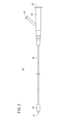
図1に示すように、本実施形態の第1実施形態に係る手技シミュレータ10Aは、血液を模した液体Lを内包する流路12と、液体Lに流れを付与する液流発生部材の一例であるポンプ13と、流路12内にカテーテルを介入させるように構成されたカテーテル挿入ポート14と、液体Lを貯留する容器の一例である水槽16とを備える。液体Lとしては、水、グリセリン、マンニトール、低級アルコールのうちの少なくとも1つから選ばれる液体を、単独あるいは混合して用いる。液体Lに適宜、造影剤、着色顔料、防腐剤、抗菌剤等を添加してもよい。As shown in FIG. 1, the
流路12は、生体組織の血管を模した組織モデル20を有する。組織モデル20は、血管モデルと捉えることもできる。組織モデル20は、硬質の樹脂ブロック内に、血管を模した管腔を有するものでもよい。組織モデル20は、カテーテル挿入ポート14の下流に設けられるとともに少なくとも2つの流路に分岐する分岐部22と、分岐部22の下流に設けられた第1の分岐流路24及び第2の分岐流路26とを有する。第1の分岐流路24と第2の分岐流路26とは、同一水平面内に設けられている。従って、第1の分岐流路24と第2の分岐流路26とは同一高さに設けられている。The
第1の分岐流路24は、第1の終端28に連通している。第2の分岐流路26は、第2の終端30に連通している。第1の終端28と第2の終端30に付与される圧力は互いに異なり、かつ、いずれの圧力も液流発生部材(ポンプ13)によって発生される圧力よりも低い。第1の分岐流路24及び第2の分岐流路26は、それぞれ組織を表現したものとなっている。このうち、第1の分岐流路24は正常な肝臓組織を表現しており、第2の分岐流路26は癌細胞が増殖した肝臓組織を表現している。The first
第1の分岐流路24に連通する第1の終端28は、第1排出口28aを構成する。第1排出口28aは、第1の分岐流路24の下流で、水槽16の水面より高い位置から水槽16へ液体Lを排出する。第1排出口28aは、外気に開放した開口部である。このため、第1の分岐流路24には下流側(第1排出口28a側)から、大気圧以外の圧力が略付与されない状態となっている。The
第2の分岐流路26に連通する第2の終端30は、第2排出口30aを構成する。第2排出口30aは、第2の分岐流路26の下流で、水槽16の底面近傍に接続している。第2排出口30aは、水槽16内に貯留された液体Lの液面よりも低い位置に設けられていればよい。水槽16内の液体Lの液面は、組織モデル20(後述する流路形成ブロック32)よりも低い位置に設定されている。サイフォンの原理により、第2の分岐流路26の下流側では、水槽16へ液体Lが流れ落ちる力が働く。これにより、第2の分岐流路26の下流側は、下流側に向かって圧が付与され続ける状態となる。第2排出口30aが設けられる高さは、水槽16の底面に限るものではなく、組織モデル20よりも低い位置であればよい。第2排出口30aを、水槽16の側面の低い位置に設けてもよい。The
第1の分岐流路24は、第1の分岐流路24の他の箇所よりも内径が小さい複数の第1小径分岐流路24aを有する。第2の分岐流路26は、第2の分岐流路26の他の箇所よりも内径が小さい複数の第2小径分岐流路26aを有する。第1の分岐流路24及び第2の分岐流路26は、それぞれ、微小血管を模した流路である。第1の分岐流路24及び第2の分岐流路26は、それぞれ、さらに内径が小さい、複数の分岐流路24b、26bを有する。すなわち、第1の分岐流路24、及び、第2の分岐流路26は、流路が枝分かれするごとに、流路の内径が小さくなっている。The
全ての流路12は内部の液体Lの流れが目視可能なように、透明な材料から形成されている。第1実施形態では、流路12の一部を構成する組織モデル20(分岐部22、第1の分岐流路24、第2の分岐流路26、第1小径分岐流路24a、第2小径分岐流路26a及びそれらの近傍箇所)が、シリコン等の透明な材料からなる流路形成ブロック32に設けた孔(空洞)によって形成されている。流路12の他の部分は、複数のチューブによって形成されている。All of the
流路形成ブロック32は、支持台33上に水平に設置されている。第1の実施形態において流路形成ブロック32は、パネル状に形成されるとともに、上面視で四角形状に形成されている。流路形成ブロック32は、少なくとも第1の分岐流路24と第2の分岐流路26を平面に保持している。なお、流路形成ブロック32の形状は四角形状に限るものではなく、平面視で円形や他の多角形状に形成されてもよい。流路形成ブロック32は、パネル状でなくてもよい。The flow
具体的に、流路12のうち、水槽16とポンプ13との間、ポンプ13と流路形成ブロック32との間、流路形成ブロック32と第1排出口28aとの間、及び流路形成ブロック32と第2排出口30aとの間が、それぞれチューブ34、36、38、40によって形成されている。Specifically, the
なお、流路12は、流路形成ブロック32を用いずに、組織モデル20がチューブで構成されてもよい。この場合、複数のチューブで構成された組織モデル20が、支持部材(例えば、支持プレート)に固定されることにより形状が維持されやすくしてもよい。第1実施形態においては分岐部22にて2つの流路に分岐するものとしたが、3つ以上に分岐するものであってもよい。The
ポンプ13は、チューブ34を介して水槽16に入れられた液体Lを汲み上げ、流路12内に、水槽16側から組織モデル20側へと向かう液流を発生させる。液体Lは、チューブ36を介して、流路形成ブロック32に形成された組織モデル20へと送られる。チューブ36は、四角形状の流路形成ブロック32の一側面32aに接続されている。流路形成ブロック32の上記一側面32aとは反対側の側面32bに、チューブ38、40がそれぞれ接続されている。チューブ38の出口が、第1の終端28(第1排出口28a)を構成している。チューブ40の出口が、第2の終端30(第2排出口30a)を構成している。手技シミュレータ10Aが設置される面からの高さを比較すると、第2排出口30aは、第1排出口28aよりも低い位置にある。チューブ40は、第1の分岐流路24の下流側と第2の分岐流路26の下流側との間に圧較差を発生させる圧較差発生部材と捉えることができる。The
第1実施形態において、ポンプ13は、第1排出口28aに与えられる大気圧及び第2排出口30aに与えられる水圧よりも高い圧力で液体Lを送液する。ポンプ13の形式は特に限定されるものではなく、例えば、遠心ポンプが挙げられる。なお、ポンプ13を、水槽16内に設置してもよい。本実施形態に適用可能な液流発生部材は、ポンプ13に限るものではなく、流路12内に一方向の液流を発生させるものであればよい。例えば、液体Lを収容したバッグを、チューブを介して流路12に接続し、組織モデル20よりも高い位置にバッグを設置して、液体Lを落差により流して、流路12に液流を発生させてもよい。In the first embodiment, the
分岐部22よりも上流には、流路12にカテーテルを介入させるためのカテーテル挿入ポート14を設ける。カテーテル挿入ポート14は、カテーテルを血管内に挿入する挿入口を模擬している。カテーテル挿入ポート14には、カテーテルを挿入できるが、流路12内の液体Lが漏れ出さないよう、図示しない弁がカテーテル挿入ポート14内に設けられている。A
なお、チューブ34、36、38、40のうち1つ以上に、バルブ、クレンメ、コック等の流量調整デバイスを設置し、流量調整デバイスにより流量を調整し、圧力を変化させることができる。さらにバルブ等を可変型電磁弁等に置き換え、PCや専用の制御装置を用いることにより、様々な条件を設定して自動制御することも可能である。In addition, a flow control device such as a valve, clamp, or cock can be installed in one or more of the
図2に示すように、手技シミュレータ10Aに使用するためのカテーテル46(バルーンカテーテル)は、カテーテル本体48と、カテーテル本体48の先端部に設けられた拡張及び収縮が可能なバルーン50と、カテーテル本体48の基端部に接続されるハブ52とを備える。バルーン50の内部は、カテーテル本体48に設けられた拡張用ルーメンを介して、ハブ52に設けられた拡張用ポート54に連通している。拡張用ポート54から拡張用液体を注入することで、バルーン50が拡張する。図2では、拡張状態のバルーン50を示している。なお、拡張用液体は、図示しないシリンジ等を用いて注入される。As shown in FIG. 2, the catheter 46 (balloon catheter) for use in the
ハブ52は、ターゲットとする組織の血管に、治療剤を注入するための注入用ポート56を有する。注入用ポート56は、カテーテル本体48の内部に設けられた注入用ルーメンを介して、カテーテル46の末端開口47に連通する。注入用ポート56から注入された治療剤は、末端開口47から血管内に投与される。なお、注入用ルーメンは、ガイドワイヤルーメンとしても機能する。The
次に、上記のように構成された手技シミュレータ10Aの作用を説明する。Next, we will explain the operation of the
図3に示すように、使用者は、カテーテル挿入ポート14を介してカテーテル46を流路12に挿入し、バルーン50を拡張していない状態で、末端開口47から模擬治療剤を投与した場合の模擬治療剤の挙動を視認できる。使用者は、模擬治療剤として、着色された液体L′(以下、着色水と呼ぶ)を投与(注入)する。バルーン50を拡張していない状態では、流路12に投与された着色水は、ポンプ13によって送液される液体Lとともに、下流側に流れる。この際、分岐部22においては、液体L及び着色水は、第1の分岐流路24及び第2の分岐流路26のいずれにも流れる。これは、ポンプ13(図1)により送り出される流圧が、第1の分岐流路24及び第2の分岐流路26の下流側の圧力のいずれよりも高いためである。後述する液体Lの液面と組織モデル20との落差が大きくないため、著しい陰圧が発生してない、すなわち圧較差以上にポンプの流れが成立するように調整されている。また着色水の移動による格差を認知するには、液体Lは透明であることが好ましい。なお、着色水には、固形塞栓物質を加えてもよい。固形塞栓物質としては、ゼラチン、球状プラスティック、蛍光片が好適に用いられる。As shown in FIG. 3, the user can visually confirm the behavior of the simulated therapeutic agent when the simulated therapeutic agent is administered from the
次に、使用者は、図4に示すように、バルーン50を拡張して分岐部22よりも上流側の流路12を閉塞させる場合の模擬治療剤の挙動を視認できる。バルーン50を拡張した状態でカテーテル本体48の末端開口47から着色水を投与する。着色水は、バルーン50によって上流側の流路が閉塞されていることから、ポンプ13による圧力を受けることが無い。このため、着色水は、着色水注入時の圧力のみが付与されて、下流側に流される。Next, as shown in FIG. 4, the user can visually confirm the behavior of the simulated therapeutic agent when the
この際、使用者が着色水を、液体Lの流れ(血流)に変化を与えることの無いよう、少量ずつ、非常に弱い圧力で注入すると、第1排出口28a側から逆流した液体Lが、分岐部22を経由して第2の分岐流路26及び第2排出口30a側へ流れる現象が生じる。微弱な圧力で投与された着色水は、第1排出口28a側から第2排出口30a側への液体Lの流れに乗り、第1の分岐流路24側には流れず、第2の分岐流路26側のみに選択的に流れていく現象が生じる。このとき、バルーン50の閉塞位置よりも下流の流路では、第2の分岐流路26から第2排出口30aへの流れ込みによる陰圧力が付与されるため、圧力値はゼロにならないが、第1排出口28a側が大気圧であることにより、相対的に第2排出口30a側よりも圧力が高くなっているからである。使用者が大気圧よりも高い圧力で着色水を注入した場合は、第2の分岐流路26側のみに選択的に流れていく現象が生じない。後述する図6は、図3の第1排出口28aからの逆流に対して、持続的な流れを発生さできるよう、かつ、図2の流路12からの流れを維持できるような構成としたものである。At this time, if the user injects the colored water in small amounts with very weak pressure so as not to change the flow of the liquid L (blood flow), the liquid L that flows back from the
これにより、手技シミュレータ10Aの使用者は、血管分岐部の上流でバルーン50を拡張し、血管を閉塞した状態で治療剤を投与するB-TACE手技をはじめとしてバルーン閉鎖手技の理解やトレーニングの習得を好適に実施できる。使用者は、目標部位の上流側で圧較差が生じていることを確認する訓練や、周囲の組織よりも低圧となっている目標部位に対して治療剤を選択的に投与する訓練を習得できる。さらに、B-TACE手技に必要な、弱い圧力でゆっくりと薬剤を投与する方法を習得できるため、ワンショットで注入する従来の造影剤や治療剤とは異なる治療手技を身に着けることができる。また、B-TACE以外でも、バルーンを用いた血流遮断技術を行った場合に、他の血流が流れ込む様子や、組織中の圧較差がある部分の手技説明やシミュレーションモデルとして使用できる。This allows the user of the
この手技シミュレータ10Aは、第1の分岐流路24及び第2の分岐流路26が形成された流路形成ブロック32を備える。この構成により、生体組織を模した第1の分岐流路24及び第2の分岐流路26の形状及び高さを所望の状態に安定して設定することができる。This
第2の終端30は、第1の分岐流路24と第2の分岐流路26よりも低い位置に配置されている。このため、第1の分岐流路24と第2の分岐流路26が液体で満たされていれば、サイフォンの原理により第2の終端30には、水槽16内に向かう圧(陰圧)が付与される。これにより簡単な構成で、第1の分岐流路24と第2の分岐流路26との間に圧較差を発生させることができる。The second
液流発生部材は、ポンプ13であるため、所望の圧力で容易かつ確実に、流路12内に流れを付与することができる。また、水槽16の液体Lを、流路12内で循環させることで、長時間の訓練を行うことができる。The liquid flow generating member is a
図1に示した手技シミュレータ10Aでは、第1の分岐流路24及び第2の分岐流路26がそれぞれ下流側接続ポート25、27を1つずつ有する組織モデル20が用いられているが、このような組織モデル20に代えて、図5に示す組織モデル20mが用いられてもよい。この組織モデル20mは、図1等に示した組織モデル20よりも流路の分岐が複雑となっており、ヒトの肝臓組織により近い構造を有している。In the
図5に示すように、組織モデル20mの第1の分岐流路24m及び第2の分岐流路26mは、それぞれ下流側接続ポート24ma、26maを複数個ずつ有する。具体的に、第1の分岐流路24mは、下流側接続ポート24maを2つ有する。例えば、第2の分岐流路26mは、下流側接続ポート26maを4つ有する。図1等に示した組織モデル20と同様に、この組織モデル20mにおいても、第1の分岐流路24m及び第2の分岐流路26mは、それぞれ複数の小径流路58(58b~58d)を有する。一例であるが、流路58aの径は2.5mmであり、これより細い流路58bの径は2mmであり、さらに細い流路58cの径は1.5mmであり、最も細い流路58dの径は1mmである。As shown in FIG. 5, the first
手技シミュレータ10Aにおいて組織モデル20mを用いることにより、手技シミュレータ10Aの使用者は、よりリアリティのあるトレーニングを実施することができる。By using the
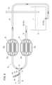
図6に示すように、本実施形態の第2実施形態に係る手技シミュレータ10Bは、血液を模した液体Lを内包する流路60と、液体Lに流れを付与する液流発生部材の一例であるポンプ13と、流路60内にカテーテルを介入させるカテーテル挿入ポート14と、液体Lを貯留する第1容器の一例である第1水槽62と、液体Lを貯留する第2容器の一例である第2水槽64とを備える。すなわち、図6は、図1の第1排出口28aを第1水槽62に接続させたものであり、図1における水槽16は、図6における第2水槽64と位置づけられる。As shown in FIG. 6, the
全ての流路60は内部の液体Lの流れが目視可能なように、透明な材料から形成されている。流路60は、生体組織の血管を模した組織モデル70(血管モデル)に連通する。組織モデル70は、シリコン等の透明な材料からなる流路形成ブロック72と、流路形成ブロック72内に設けられるとともに、流路形成ブロック72の一端側から他端側に通じる管腔とを有する。流路形成ブロック72は、第2水槽64の上部(第2水槽64内の液体Lの液面よりも上方)に設置される。第1水槽62は、流路形成ブロック72の上面よりも上部に液面を有するように設置される。All of the
組織モデル70は、複数の分岐流路として、第1の分岐流路74と、第2の分岐流路76とを有する。第1の分岐流路74は、第1の終端78に連通している。第2の分岐流路76は、第2の終端80に連通している。第2の分岐流路76は組織モデル70より低い位置であってもよい。第1の終端78と第2の終端80に付与される圧力は互いに異なり、かつ、液流発生部材(ポンプ13)によって発生される圧力よりも低い。第1の分岐流路74及び第2の分岐流路76は、それぞれ肝臓組織を表現したものとなっている。このうち、第1の分岐流路74は正常な肝臓組織を表現しており、第2の分岐流路76は癌細胞が増殖した肝臓組織を表現している。The
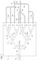
図7に示すように、組織モデル70は、分岐部82aで主流路81から2本の流路83に分岐しており、さらに下流に設けられた分岐部82b、82cで2回ずつ分岐し、最終的に人の肝臓の部位を想定した計8本の流路S1~S8に分岐している。分岐部82a~82cは、第2実施形態ではいずれも2本の流路に分岐するものとしたが、複数本の任意の数の分岐とすることができる。As shown in FIG. 7, the
各分岐部82a~82cの下流には、分岐した流路同士をつなぐ連結流路85が複数本ずつ(この実施形態では2本ずつ)設けられている。各連結流路85は、組織の側副血行路を模したものである。組織モデル70における流路の径(内径)は、分岐する毎に、元の(分岐前の)流路の径よりも細くなるように設計されている。分岐後の径は、分岐前の径の70~90%となるよう設計されることが好ましい。この実施形態では、分岐後の径は、ヒトの肝臓組織に近づけるため、分岐前の径の80%程度(78~82%)となるよう設計されている。第2実施形態における各流路の長さ及び径は、図10に示す表1の通りである。Downstream of each
図7に示すように、流路S1~S3、S7、S8は、流路形成ブロック72に接続されたチューブ86を介して下流で合流し、単一の流路となる。すなわち、チューブ86は、流路S1~S3、S7、S8に接続された複数の接続流路86aと、複数の接続流路86aと合流部86bを介して繋がった1つの合流路86cとを有する。同様に、流路S4~S6は、流路形成ブロック72に接続されたチューブ88を介して下流で合流し、単一の流路となる。すなわち、チューブ88は、流路S4~S6に接続された複数の接続流路88aと、複数の接続流路88aと合流部88bを介して繋がった1つの合流路88cとを有する。正常な肝臓組織を表現した第1の分岐流路74は、流路S1~S3、S7、S8を有する。癌細胞が増殖した肝臓組織を表現した第2の分岐流路76は、流路S4~S6を有する。As shown in FIG. 7, the flow paths S1-S3, S7, and S8 merge downstream via a
図6において、ポンプ13は、第2水槽64に入れられた液体Lを汲み上げ、流路60内に、第2水槽64側から組織モデル70側へと向かう液流を発生させる。具体的に、ポンプ13は、第2水槽64に接続されたチューブ90を介して第2水槽64から液体Lを汲み上げ、チューブ91を介してT字形管92に送られる。T字形管92の一端92aは、流路形成ブロック72に接続されたチューブ94に接続されている。T字形管92の他端92bには、カテーテル挿入ポート14が設けられている。ポンプ13によって汲み上げられた液体Lは、T字形管92を介して、組織モデル70へと送られる。In FIG. 6, the
第1水槽62及び第2水槽64は、それぞれ液体Lを貯留し、互いに液面高さが異なる。具体的に、第1水槽62内の液体Lの液面は、第2水槽64内の液体Lの液面及び組織モデル70(流路形成ブロック72)よりも高い位置にある。The
一端が第1の分岐流路74に接続されたチューブ86の他端は、第1の終端78を構成しており、第1水槽62の貯留槽内に連通するとともに第1水槽62内の液体Lの液面よりも低い位置に接続している。第2実施形態では、チューブ86の他端(第1の終端78)は第1水槽62内の液体Lに水没する態様で配置されているが、このような構成に代えて、チューブ86の他端は第1水槽62の壁に接続されて第1水槽62の貯留槽と連通してもよい。The other end of the
第1水槽62には、第1の終端78よりも高い位置で、排出流路の一例であるチューブ96の一端(入口96a)が接続されている。チューブ96の他端(出口96b)は、チューブ96の一端よりも低く、かつ第2水槽64内の液体Lの液面よりも高い位置に設けられている。チューブ86を介して第1水槽62内に液体Lが流入し、第1水槽62内の液体Lの液面がチューブ96の入口96aの高さに達すると、液体Lはチューブ96を介して第2水槽64内へと排出される。従って、第1水槽62内の液体Lの液面高さは、チューブ96の入口96aの高さで一定に保たれ、訓練中に第1水槽62から液体Lがあふれ出ることを抑制する。チューブ96は、チューブ86から流れ込む液体Lの量と、チューブ101から流れ込む液体Lの量との和に対して、十分排出可能な径を有する。これにより、第1水槽62の液面を一定に保つとともに、チューブ86を介して、第1の分岐流路74(正常な肝臓組織を模す)に付与する圧(バックフロー)を、長時間にわたって一定にすることができる。One end (
一端が第2の分岐流路76に接続されたチューブ88の他端は、第2の終端80を構成しており、第2水槽64の貯留槽内に連通するとともに第2水槽64内の液体Lの液面よりも低い位置で接続している。チューブ88は、第1の分岐流路74の下流側と第2の分岐流路76の下流側との間に圧較差を発生させる圧較差発生部材と捉えることができる。第2実施形態では、チューブ88の他端(第2の終端80)は第2水槽64の壁に接続されて第2水槽64の貯留槽と連通しているが、このような構成に代えて、チューブ88の他端が第2水槽64内の液体Lに水没する態様(第2水槽64の壁に接続されていない態様)で配置されてもよい。The other end of the
図6において、第1の分岐流路74と連通した第1の終端78と、第2の分岐流路76と連通した第2の終端80とは、圧力値が異なる。このため、第1の分岐流路74と第2の分岐流路76との間には圧較差が生じている。具体的には、第1の分岐流路74には、第1水槽62内の液体Lの水位と組織モデル70(流路形成ブロック72)との高低差に応じた圧力(陽圧)がかかり、第2の分岐流路76には、組織モデル70(流路形成ブロック72)と第2水槽64との高低差に応じた圧力(陰圧)がかかっている。従って、第1の分岐流路74と第2の分岐流路76との間では、第1の分岐流路74にかかる圧力が相対的に高く、第2の分岐流路76にかかる圧力が相対的に低い。6, the
ポンプ13が発生する流圧は、第1の終端78及び第2の終端80に付与される圧力よりも高い。すなわち、分岐部82aの上流側に付与される単位断面積あたりの圧力は、第1の終端78における単位断面積あたりの圧力よりも大きい。また、分岐部82aの上流側に付与される単位断面積あたりの圧力は、第2の終端80における単位断面積あたりの圧力よりも大きい。このため、図8に示すように、ポンプ13によって液体Lに流れが付与された流路60内に、カテーテル挿入ポート14からカテーテル46を挿入し、分岐部82aの上流側にカテーテル46の末端を配置し、バルーン50を拡張しない状態でカテーテル46の末端開口47から治療剤(着色水)を投与(注入)すると、第1の分岐流路74側と第2の分岐流路76側の両方に流れていく。The flow pressure generated by the
一方、図9に示すように、分岐部82aの上流でバルーン50を拡張することにより流路を閉塞した状態で、カテーテル46の末端開口47から治療剤を模擬した着色水を微弱な圧力で投与すると、上記した圧較差により、組織モデル70内では第1の分岐流路74側から第2の分岐流路76側へと液体Lが流れる現象が生じる。従って、末端開口47から吐出された着色水は、第1の分岐流路74側には流れず、第2の分岐流路76側(流路S4~S6)のみに流れていく現象が生じる。すなわち、分岐流路が接続する終端の圧力の差に基づき、カテーテル46で塞栓したときと、塞栓していないときとで、S1~S3、S7、S8で着色水の流れる方向が図8とは反対となる。このときに第1水槽62の液体Lの液面が組織モデル70の上面より同じ、または1~5cm、好ましくは1~3cm程度高い場合、組織モデル70内の液体Lの流れが視認しやすい流速となる。On the other hand, as shown in Fig. 9, when the flow path is blocked by expanding the
従って、第1実施形態と同様に、第2実施形態に係る手技シミュレータ10Bの使用者は、血管分岐部の上流でバルーン50を拡張し、血管を閉塞した状態でゆっくりと治療剤を投与した場合、下流側に圧較差の生じ得る条件があることを目視で確認できる。これにより、目標部位が低圧であることが確認されれば、使用者は、目標部位に選択的に投与が可能であることを実感することができる。また、血管を閉塞した状態で、高い圧力で治療剤を投与した場合、使用者は、バルーン50で閉塞した下流側において圧較差を利用した投与はできないことを理解することができる。Therefore, similar to the first embodiment, a user of the
また、図6に示したように、この手技シミュレータ10Bは、液体Lを貯留する第1水槽62及び第2水槽64を備え、第1水槽62内の液体Lの液面は、第2水槽64内の液体Lの液面よりも高い位置に設定されている。第1の終端78は、第1水槽62の貯留槽内に連通するとともに、第1水槽62内の液体Lの液面よりも低い位置に配置されている。第2の終端80は、第2水槽64の貯留槽内に連通するとともに第2水槽64内の液体Lの液面よりも低い位置に配置されている。第1の分岐流路74及び第2の分岐流路76は、第1水槽62内の液体Lの液面と、第2水槽64内の液体Lの液面との間の高さに配置される。この構成により、流路60内でバルーン50を拡張したときに、第1の終端78から空気が流入することがなく、第1の分岐流路74側から第2の分岐流路76側へと向かう流れを連続的に作り出すことができる。すなわち、図1においては第1の終端28からバルーンを膨らました際に一定以上時間がたつと空気が流入しうるが、図6では空気が流入しないように構成されている。また、図6の手技シミュレータ10Bにおいて、チューブ88、及び/または、第2水槽64を省略することができる。すなわち、第2の分岐流路76に対して、チューブ86を陽圧発生部材としても、手技シミュレータ10Bと同様のシミュレータが実現できる。6, the
この手技シミュレータ10Bは、第1の終端78よりも高い位置に配置された入口96aを有する排出流路(チューブ96)を備え、排出流路は、第1水槽62から第2水槽64へと液体Lを排出する。この構成により、バルーン50が流路60内に挿入されていないとき、または、バルーン50が流路60内で拡張されていないときに、第1の分岐流路74から第1の終端78を介して第1水槽62に液体Lが流入する。その際、チューブ96は十分な内腔を有するため、所定量を超える分の液体Lは、排出流路(チューブ96)により第2水槽64へと排出される。このため、持続的にシミュレーションを行うことができる。また、チューブ101をT字形管92から第1水槽62へさらに接続することで、バルーン50を拡張したときに、第1水槽62に液体Lを補充することができる。これにより、第1の分岐流路74から第2の分岐流路76の流れを、より長い時間発生させることが可能になり、長時間のトレーニングが可能となる。This
図7に示したように、第2実施形態においては、複数の側副血行路の役割を示す連結流路85を有するため、バルーン50の拡張位置を分岐部82aの上流のみならず、その下流の様々な位置で試すことができる。例えば、図7において、連結流路85aに対して若干だけ上流の位置P1にバルーン50を配置して、拡張せずに着色水を強い圧力で投与した場合(例えば、1mLの着色水を数秒間で注入する場合や、造影剤を注入して血管造影する場合と同程度の注入圧力)、着色水は、分岐部82bの下流の流路S5~S8全体に流れるとともに、位置P1のすぐ下流の連結流路85aを介して一部が流路S1~S4側にも流れて行く。As shown in FIG. 7, in the second embodiment, since the connecting
また、位置P1にバルーン50を配置して拡張し、位置P1で流路を塞いで着色水をゆっくりと投与した場合、そのすぐ下流の連結流路85aには、流路S4~S6(第2の分岐流路76)を介してチューブ88からの陰圧がかかるため、流路S4~S6側には着色水が選択的に流れる。このため、投与された着色水は、接続流路86aからの圧力により流路S7、S8には流れない。In addition, if the
位置P2にバルーン50を配置して拡張した場合に、着色水を強い圧力で注入すれば、S5~S8に流れるが、着色水を微弱な圧力で注入すれば、流路S5及びS6側のみに、より選択的に流れる現象が生じることが示せるということである。これは、位置P2のすぐ下流に連結流路85bがあるためである。使用者は、側副血行路の存在を容易に視認できるため、バルーン50を拡張させる位置を選択するトレーニングや、適切な注入圧を習得することができる。これにより、使用者は、例えば、患者の正常組織へ到達する抗がん剤を減らす手技が習得できる。When the
このように、第2実施形態では、様々な位置にバルーン50を配置し拡張させた場合に生じる現象を確認することができる。また、血管造影手技と異なる治療剤投与手技を模擬することができ、ターゲット組織へ選択的に、治療剤を効果的に投与する訓練を行うことができる。なお、流路S1~S8の圧較差の組み合わせは、チューブ86、88の接続部位を変えることで自由に設定変更が可能である。In this way, in the second embodiment, it is possible to confirm the phenomenon that occurs when the
ここで、実際の血管の現象に近く、理想的な圧較差による血流の変化を生じさせる条件としては、図6において、例えば、ポンプ13による流圧が130mmHg程度のとき、第2の分岐流路76に連通する低圧の排出口(第2の終端80)側の圧力はそれぞれ64mmHg以下とし、第1の分岐流路74に連通する高圧の排出口(第1の終端78)側の圧力は、それぞれ130mmHgよりも低く、第2の分岐流路76に連通する排出口(第2の終端80)側の圧力よりも高いことが望ましい。The ideal conditions for creating a change in blood flow due to a pressure difference that is close to the phenomenon occurring in actual blood vessels are as follows: in FIG. 6, for example, when the flow pressure from the
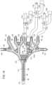
図11に示すように、第3実施形態に係る手技シミュレータ10Cは、第1水槽116と、第2水槽110と、血液を模した液体Lを内包する流路160と、生体組織の血管を模した組織モデル120(血管モデル)とを有する。組織モデル120は、アクリル樹脂やポリカーボネート等の透明な材料からなる流路形成ブロック112に設けられている。組織モデル120は、シリコン樹脂等の軟質材(ゴム材)により構成されてもよい。具体的に、組織モデル120は、樹形図状に形成された流路形成ブロック112と、その内部に設けた孔(空洞)とによって構成される。流路形成ブロック112は、第2水槽110の上部(第2水槽110内の液体Lの液面L2よりも上方)に設けられた台座111の上に設置されている。As shown in FIG. 11, the
図13に示すように、組織モデル120は、複数の分岐流路を備えている。液体Lが流入する始端部112a側に最も近い部分に、分岐部122が形成されている。この分岐部122からは、2つの第1分岐流路122a、122bが分岐して延びている。第1分岐流路122a、122bは、分岐部122の上流側の直線部112bに対して左右に対称な角度で分岐し、かつ、分岐部122から次の分岐までの長さは等しい。2つの第1分岐流路122a、122bは、分岐部122、第2分岐部124、130を頂点とした二等辺三角形または正三角形を形成するように延びている。第1分岐流路122aの末端には第2分岐部124が設けられており、第2分岐部124からは、第2分岐流路124a、124bがさらに分岐して延びている。また、第1分岐流路122bの末端には第2分岐部130が設けられており、第2分岐部130からは、第2分岐流路130a、130bが分岐して伸びている。As shown in FIG. 13, the
上記の第2分岐流路124a、124b、130a、130bの末端部には、第3分岐部126、128、132、134がそれぞれ設けられている。それらの第3分岐部126、128、132、134からは、第3分岐流路126a、126b、128a、128b、132a、132b、134a、134bがそれぞれ分岐して延びている。すなわち、各分岐部122~134において、各々2本の分岐流路に分岐しており、3段階の分岐部を経て、8本の第3分岐流路126a、126b、128a、128b、132a、132b、134a、134bに分岐している。組織モデル120において、どの分岐流路に模擬腫瘍を接続した場合であっても、同等な条件(流動抵抗)を発生できるように、各分岐流路が等しい長さに形成され、直線部112bの長軸方向に対して左右に対称になるように同じ平面上に形成する。分岐部122~134の接続角度、例えば60°とすることができる。なお、分岐部122~134の分岐数は2本に限定されるものではなく、複数本の任意の数に分岐してもよい。The
また、各分岐部122~134の下流には、分岐した流路同士をつなぐ連結流路122c~134cが複数本ずつ設けられている。図示の例では、各分岐部122~134に対して2~3本の連結流路122c~134cが設けられている。これらの、連結流路122c~134cは、組織の側副血行路を模したものである。組織モデル120において、分岐流路122a~134bの径(内径)は、分岐する毎に、分岐前の径の70~90%となるように設計されていることが好ましい。この実施形態では、分岐後の径は、ヒトの管組織に近づけるために、分岐前の径の80%程度(78~82%)となるように設定されている。流路160の直線部112bの内径は、例えば5mm程度とすることができる。この場合、第1分岐流路122a、122bの内径は4mm程度とすることができる。また、第2分岐流路124a、124b、130a、130bの内径は3.3mm程度とすることができる。さらに、末端の第3分岐流路126a、126b、128a、128b、132a、132b、134a、134bの内径は2.8mm程度とすることができる。各連結流路122c~134cの内径は、1.5~1.8mmとすることができる。In addition, downstream of each branch 122-134, multiple connecting
上記の組織モデル120の8本の第3分岐流路126a、126b、128a、128b、132a、132b、134a、134bの末端には、それぞれ接続ポート141~148が設けられている。図11に示すように、接続ポート141~148には、配管151~158がそれぞれ接続されている。接続ポート141~148は、配管151~158の内側で嵌合させる。配管151~158は、全て第1水槽116に接続されている。各配管151~158の内径は、例えば2.1mm程度とすることができる。配管151~158は、途中で合流して集合配管を構成してもよい。なお、第1水槽116に向かう複数の配管151~158の少なくとも2つの配管には、三方活栓172a~172c(流路切換手段)が設けられている。三方活栓172には、腫瘍模擬配管174a~174cの一端部が脱着可能に接続されている。図示の例では、3つの配管152、153、154にそれぞれ三方活栓172a、172b、172cが取り付けられている。また、三方活栓172が取り付けられていない配管151、155~158には、ポート150が装着されている。なお、三方活栓172は、全ての配管151~158に設けられていてもよい。配管151~158において三方活栓172は、どの位置に設けられていてもよい。The eight
ポート150は、手技シミュレータ10Cをセットアップ作業時に配管151、155~158内の気泡の除去を可能とするべく、シリンジの先端ノズルを挿入可能な弁を備えて構成されている。ポート150の弁は、シリンジの先端ノズルを挿入すると開いて配管151、155~158内の気泡をシリンジで吸い出すことが可能となっている。ポート150は、シリンジの先端ノズルを引き抜くと閉塞する。
配管154の三方活栓172cは、接続ポート144に対して、第1水槽116または腫瘍模擬配管174cの終端を選択的に連通させることができる。三方活栓172cにより接続ポート144と腫瘍模擬配管174cとを連通させると、液体Lは腫瘍模擬配管174cの終端のフィルタ159から流出し、第1水槽116には流出しない。配管152、153に設けられた三方活栓172a、172bも、同様にして、接続ポート142、143と腫瘍模擬配管174a、174c、あるいは、接続ポート142、143と第1水槽116、のいずれかで選択的に連通させる。これにより、三方活栓172の操作のみで、模擬腫瘍(フィルタ159)のある流路を切り換えることができる。The three-
腫瘍模擬配管174a~174cの他端部は、終端174を有する。終端174は、第1水槽116の液面L1よりも低い位置に設定されることで圧較差発生部材として捉えることができる。腫瘍模擬配管174a~174cは、模擬腫瘍を表現するべく、組織モデル120と腫瘍模擬配管174a~174cの終端174との落差の分だけ、他の配管よりも液体Lが流れやすくなっている。腫瘍模擬配管174a~174cの終端174には、フィルタ159が設けられている。フィルタ159については後述する。The other ends of the
図11の例では腫瘍模擬配管174a~174cの終端174が、第2水槽110の外側に配置されているが、本実施形態はこれに限定されるものではなく、腫瘍模擬配管174a~174cが第2水槽110の内部に引き回されてその終端174が第2水槽110内に配置されていてもよい。この場合には、腫瘍模擬配管174a~174cから排出される液体Lを第2水槽110内に回収することができる。腫瘍模擬配管174a~174cは少なくとも一部分が、組織モデル120より低い部分の配置されている。In the example of FIG. 11, the
フィルタ159は、円筒状の透明な樹脂製筐体の内部に、フィルタを内蔵している。フィルタは、孔径数μm程度の微細な細孔を有する多孔質部材である。好ましくはポリエーテルスルホン(PES)、ポリウレタン等から製造された膜状部材や、ポリエチレン焼結体等を使用することができる。塞栓剤のような模擬治療剤の投与訓練をする際に、フィルタ159で塞栓剤を捕捉することができる。さらに、液体Lを通過可能とし、塞栓剤のみ補足するようなフィルタ159とするのが好ましい。このように構成すると、塞栓剤を注入してゆくことにより、フィルタ159が徐々に塞栓されて流体の流れ方に変化が起こり、逆流や液体Lの停滞が発生する。このようにして、組織モデル120は、腫瘍細胞に繋がる血管が塞栓される様子を再現し、使用者に塞栓剤注入の治療効果を認知させることができる。The filter 159 is built into a cylindrical transparent resin housing. The filter is a porous member having fine pores with a pore diameter of about several μm. A membrane member made of polyethersulfone (PES), polyurethane, or sintered polyethylene can be preferably used. When training the administration of a simulated therapeutic agent such as an embolic agent, the filter 159 can capture the embolic agent. Furthermore, it is preferable to make the filter 159 pass through the liquid L and capture only the embolic agent. With this configuration, the filter 159 is gradually blocked by injecting the embolic agent, causing a change in the flow of the fluid, resulting in a backflow and stagnation of the liquid L. In this way, the
なお、フィルタ159の種類や配置、及びフィルタ面積を適宜調整してもよく、また塞栓材に含まれる塞栓物の直径(サイズ)を変えてもよい。フィルタ159及び塞栓物のサイズや量を調整することで、閉塞する時間をコントロールすることができ、様々な条件で手技のシミュレーションを行うことができる。また、青色等に着色した模擬塞栓物と、白色のフィルタを用いれば、白色のフィルタに青色の模擬塞栓物が蓄積する様子を容易に視認することができる。さらに、フィルタ159に塞栓剤が捕捉された後は、腫瘍模擬配管174a~174cとフィルタ159を流路から取り外して廃棄することができる。これにより、流路160内に塞栓剤が混入しにくくなるため、訓練を連続して行うことができる。バルーン50による流向変化のみならず塞栓による流れる速さの変化をみることで、使用者は、塞栓治療法をより深く理解することができる。The type, arrangement, and filter area of the filter 159 may be adjusted as appropriate, and the diameter (size) of the embolic matter contained in the embolic material may be changed. By adjusting the size and amount of the filter 159 and the embolic matter, the occlusion time can be controlled, and the procedure can be simulated under various conditions. In addition, by using a simulated embolic matter colored blue or the like and a white filter, the accumulation of the blue simulated embolic matter on the white filter can be easily visually confirmed. Furthermore, after the embolic agent is captured by the filter 159, the
第1水槽116は、組織モデル120から排出された液体Lの出口である排出ポート161~168と、第1水槽116に溜まった液体Lを第2水槽110に還流させるドレインチューブ170とを備えている。排出ポート161~168は、組織モデル120の末端の接続ポート141~148にそれぞれ対応して設けられている。排出ポート161~168は、配管151~158を介して接続ポート141~148にそれぞれ接続されている。The
図12に示すように、排出ポート161~168は、第1水槽116の側壁部に開口している。これらの排出ポート161~168は、第1水槽116に貯留される液体Lの液面L1よりも低い位置となるように、ドレインチューブ170よりも低い位置に開口している。一方、ドレインチューブ170は、組織モデル120と略同じ高さに設けられている。ドレインチューブ170は、第1水槽116から第2水槽110に向けて延びており、第1水槽116に集まった液体Lを第2水槽110に還流させるように構成されている。第1水槽116の液面L1の位置がドレインチューブ170の高さになると、液体Lが第2水槽110に還流するため、第1水槽116の液面L1の位置は、ドレインチューブ170の高さと同じとなる。第1水槽116の下には、支持部材117が配置されている。支持部材117は、ドレインチューブ170の高さが組織モデル120の高さと略同じとなるか僅かに高くなるように設定されている。液面L1の高さが組織モデル120の高さと同じとなっているため、組織モデル120は液体Lで常に満たされるとともに、組織内の圧較差を再現できるように、ゆっくりと液体Lを流すことができる。As shown in FIG. 12, the drain ports 161-168 open to the side wall of the
なお、ドレインチューブ170は、排出ポート161~168を介して流入する液体Lの流量に対してオーバーフローしない内径に形成されていることが好ましい。そのため、ドレインチューブ170の内径は、ドレインチューブ170の断面積Aが8本の配管151~158の流路断面積の合計Bに対して、例えば、60%以上となるように設定することが好ましい。配管151~158の内径が2.1mmの場合には、流路断面積の合計Bは、33.94mm2となる。この場合、ドレインチューブ170の内径を10mmとすると、その断面積Aは28.14mm2となるため、AがBの83%となり、第1水槽116からの液体Lの排出を確実に行うことができる。従って、ドレインチューブ170の内径は、10mm以上とすればよく、例えば10~12mm程度とすることができる。 The
従って、排出ポート161~168は、第1水槽116の液面L1よりも下側に接続される。このため、組織モデル120の流路160(図1参照)の内圧を高めることや、逆流させることなく、血液を模した液体Lを流通させることができる。そのため、ポンプ113の液体Lの吐出圧力を少なくすることができる。これにより、流路160内の液体Lの流れを緩やかにして、圧較差の発生及び圧較差による逆流といった現象を、緩やかな流れの下で再現することができる。本実施形態では、流路160のうちの分岐前の流路(直線部112b)を除く箇所において、バルーン50(図14参照)を作用させる訓練を行う場合、図6のようなチューブ101を設けることなく、第1水槽116の液面を一定に保つことができる。これにより、第1水槽116の液面高さは一定に維持されるため、正常な肝臓組織を模した分岐流路に対する圧較差を、長時間にわたって、安定的に発生させることができる。Therefore, the
ポンプ113は、第2水槽110内に設けられている。ポンプ113は、チューブ118を介して組織モデル120の始端部112aに接続されている。ポンプ113は、第2水槽110内の液体Lを汲みだして組織モデル120の流路160に液体Lを供給する。ポンプ113による流圧は、第1水槽116の液面L1の位置及び液体Lの流動抵抗に応じた圧力となる。The
チューブ118には、組織モデル120の流路160にカテーテル46(図2参照)を介入させるためのカテーテル挿入ポート114が設けられている。カテーテル挿入ポート114には、カテーテル46を血管内に挿入する挿入口を模擬している。カテーテル挿入ポート114には、カテーテル46を挿入できるが、流路160内に液体Lが漏れ出さないように、図示しない弁が設けられている。The
次に、以上のように構成された手技シミュレータ10Cの作用を説明する。Next, we will explain the operation of the
手技シミュレータ10Cに使用するためのカテーテル46は、カテーテル挿入ポート114(図11参照)を介して、組織モデル120の流路160内に挿入される。配管154に設けられた三方活栓172によって、接続ポート144の配管154が、腫瘍模擬配管174cに連通すると同時に、第1水槽116側への流れを止める。図14に示すように、配管154に設けられた三方活栓172cによって、接続ポート144の配管154と、腫瘍模擬配管174cとを連通させると同時に、第1水槽116側への流れを止める。その他の接続ポート141~143、145~148は、第1水槽116に連通している。これにより、接続ポート144を模擬腫瘍部へ接続する血管、その他の接続ポート141~143、145~148を正常組織へ接続する血管と見立てることができる。接続ポート144に向かう流路が第1の分岐流路に対応し、他の接続ポート141~143、145~148に向かう流路が第2の分岐流路に対応する。使用者は、第3分岐部128よりも上流の部分でバルーン50を拡張して第2分岐流路124bを閉塞させる。そして、カテーテル46の末端開口47から治療剤を模した着色水または着色塞栓剤を投与する。このとき、着色水または着色塞栓剤は、バルーン50による閉塞のためにポンプ113による圧力を受けることがない。このため、着色水または着色塞栓剤は、注入時の圧力のみが付与されて、下流側、すなわち腫瘍模擬配管174cの多端部に向かって流される。The
図14では、三方活栓172cにより、第3分岐流路128bにおいて、模擬腫瘍に相当する腫瘍模擬配管174cを通じて液体Lが優先的に排出される。その一方で、第3分岐流路128a側は、第1水槽116の液面L1の位置が組織モデル120と略同じ高さとなっているために、液体Lが接続ポート143から第1水槽116側へ流出しない。さらに、このとき、接続ポート143は、三方活栓172bによって、第1水槽116と連通し、かつ、腫瘍模擬配管174bと連通していない状態である。このため、第3分岐流路128bから液体Lが排出されるとともに、第3分岐流路128aから液体Lが逆流して、第3分岐流路128bに向かって流れ込む現象が生じる。そのため、カテーテル46から投与された着色水は、液体Lの流れに乗って、第3分岐流路128bに選択的に流れていく現象が生じる。すなわち、手技シミュレータ10A、10Bと同じ液体Lの流れの変化を再現できる。In FIG. 14, the three-
治療剤として着色塞栓剤を用いた場合には、フィルタ159に着色塞栓剤が目詰まりすることで、液体Lの流れが徐々に遅くなり、やがて流れが止まる。使用者は、塞栓剤による治療効果を目視で確認することができる。塞栓剤は、フィルタ159に捕捉されるため、第2水槽110内に流入しない。このため、その後の別の分岐流路を用いた手技のシミュレーションを支障なく続行することができる。使用した塞栓剤は、フィルタ159及び腫瘍模擬配管174a~174cとともに取り外して廃棄できるため、片付けが簡便になって好適である。図14では、三方活栓172cを切り替えて、第1水槽116へ液体Lの流れを遮断し、腫瘍模擬配管174cへ流路を切り替えることで、腫瘍模擬配管174cをターゲット部位としてトレーニングを行える。トレーニング後は、腫瘍模擬配管174c及びフィルタ159cを、三方活栓172cから取り外して廃棄することができる。When a colored embolic agent is used as a therapeutic agent, the colored embolic agent clogs the filter 159, gradually slowing down the flow of the liquid L, and eventually stopping the flow. The user can visually confirm the therapeutic effect of the embolic agent. The embolic agent is captured by the filter 159 and does not flow into the
次に、別の第3分岐流路128bに、模擬腫瘍の位置を切り換えるべく、三方活栓172の連通状態を切り換える。図15に示す例では、接続ポート144の配管154に設けられた三方活栓172cを操作することで、腫瘍模擬配管174cへの流れを遮断するとともに、第1水槽116に連通させる。さらに、接続ポート143の配管153に設けられた三方活栓172bを操作して、腫瘍模擬配管174bに連通させるとともに、接続ポート143から第1水槽116への流路を遮断する。すなわち、接続ポート143の下流側に模擬腫瘍を設定する。その他の接続ポート141、142、144~148は、第1水槽116に連通することで、正常組織を模擬させることができる。すなわち、第1の分岐流路が接続ポート143に向かう流路に切り換わり、その他の接続ポート141、142、144~148に向かう流路が第2の分岐流路となる。Next, the communication state of the three-
このとき、分岐部128よりも上流の部分でバルーン50を拡張して第2分岐流路124bを閉塞させる。そして、カテーテル46の末端開口47から治療剤を模した着色水または着色塞栓剤を投与する。第3分岐流路128aは、模擬腫瘍に相当する接続ポート143の腫瘍模擬配管174bを通じて液体Lが優先的に流出する。その一方で、第3分岐流路128bは、第1水槽116の液面L1の位置が組織モデル120と略同じ高さとなっているために、液体Lが接続ポート143からは殆ど流出しない。そのため、第3分岐流路128aから液体Lが排出されるとともに、第3分岐流路128bから液体Lが逆流して、第3分岐流路128aに流れ込む現象が生じる。そのため、カテーテル46から投与された着色水または着色塞栓剤は、液体Lの流れに乗って、模擬腫瘍に繋がる第3分岐流路128aに選択的に流れていく現象が生じる。At this time, the
このように、三方活栓172を操作するだけで、模擬腫瘍に繋がる分岐流路を変えることができ、複数の分岐流路124a~134bを用いた手技のシミュレーションを容易に行うことができる。これにより、模擬腫瘍に繋がる分岐流路と、模擬正常組織に繋がる分岐流路と、を簡便に切り替えてトレーニングをすることができる。In this way, the branch flow path connected to the simulated tumor can be changed simply by operating the three-
本実施形態の手技シミュレータ10Cは、液体Lを貯留する第1水槽116と、複数の第3分岐流路126a~134bと第1水槽116とを各々接続する複数の配管151~158と、複数の配管151~158の少なくとも1つに設けられ、配管151~158から分岐して終端174が第1水槽116の液面L1よりも低い位置に設定された腫瘍模擬配管174a~174cと、配管151~158と腫瘍模擬配管174a~174cとの分岐部に設けられ、腫瘍模擬配管174a~174cを第1水槽116及び腫瘍模擬配管174a~174cのいずれか一方に選択的に連通させる三方活栓172a~172c(流路切換手段)と、を備える。このように構成することにより、三方活栓172a~172cを操作するだけで、模擬腫瘍の部位を変えることができ、組織モデル120の複数の第3分岐流路126a~134bを用いた手技シミュレーションを簡単に実施することができる。The
上記の手技シミュレータ10Cにおいて、第2分岐流路124a~130b、及び第3分岐流路126a~134bは、第1水槽116の液面L1と同じ高さにある。このように構成することにより、分岐流路124a~134bに、模擬腫瘍を再現に必要な圧較差以外の差圧を発生させない。このため、再現性が高く、均質な訓練を実施することができる。In the above-mentioned
上記の手技シミュレータ10Cにおいて、腫瘍模擬配管174a~174cの終端174は、フィルタ159を有する。フィルタ159により、液体Lを回収しながら、治療剤として用いる塞栓剤を分離除去することができる。これにより、流路160への塞栓剤の混入を低減するとともに、塞栓剤が、フィルタ159から腫瘍模擬配管174a~174cに向かって蓄積する様子を確認することができる。この際、着色した塞栓剤の付着により、塞栓状態を視覚的に確認することができて好適である。また、使用後のフィルタ159は、腫瘍模擬配管174a~174cの少なくとも1つとともに組織モデル120から取り外して廃棄することができるので、組織モデル120内及び流路160内に混入した塞栓剤の処理が不要となり、片付け作業を簡便化できる。In the above-mentioned
上記の手技シミュレータ10Cにおいて、組織モデル120は、分岐前の流路(直線部112b)の長軸方向を軸として、線対称に分岐流路が分岐してもよい。これにより、左右の分岐流路の流路長さが略同じとなり、模擬腫瘍(フィルタ159)の位置を左右入れ替えても同等の条件で手技のシミュレーションを行うことができる。In the above-mentioned
上記の手技シミュレータ10Cにおいて、組織モデル120は、分岐部122~134を頂点とした略二等辺三角形状または正三角形状に分岐してもよい。さらに、この場合、最初の分岐部122から末端の接続ポート141~148までの長さが略等しくなるように形成されていてもよい。これにより、いずれの第3分岐流路126a~134bに模擬腫瘍(腫瘍模擬配管174a~174c及びフィルタ159)を接続した場合であっても、同等の条件で手技のシミュレーションを行うことができる。In the above-mentioned
上記の手技シミュレータ10Cにおいて、第1水槽116の液面L1よりも低い位置に液面L2を有する第2水槽110を備え、ポンプ113(液流発生部材)が第2水槽110の液体Lを汲み上げて流路160の上流側に供給するようにしてもよい。この場合には、第1水槽116の液体Lを第2水槽110に還流させるドレインチューブ170を備えていてもよい。これにより、液体Lを循環させて使用することができ、長時間に亘って手技のシミュレーションを行うことができる。The above-mentioned
なお、組織モデル120に接続される配管151~158の全部または一部には、クレンメ(流量調整手段)が取り付けられていてもよい。クレンメは、配管151~158の流路の断面積を減少させることができる。すなわち、クレンメによって配管151~158の断面積が変化して、流動抵抗(流量)を変化させることができる。ポンプ113によって一定流量で流れ込む液体Lに対して、クレンメで配管151~158の流動抵抗を増加させると、そのクレンメが接続された分岐流路の内圧が高まり、圧較差を発生させることができる。すなわち、クレンメは、圧較差発生部材としての機能を果たすことができる。これにより、さらに圧較差の発生条件を複雑化させることができるため、上級者向けの訓練が可能となる。Note that clamps (flow rate adjusting means) may be attached to all or some of the pipes 151-158 connected to the
図16の第3実施形態の変形例に係る手技シミュレータ10Dでは、第1水槽180が上方から見てC字状に形成されている。第1水槽180は、組織モデル120の末端の接続ポート141~148の各々と、第1水槽180との距離が概ね同一となるように、組織モデル120の接続ポート141~148を取り囲むように側部180aが形成されている。接続ポート141~148には、それぞれチューブ181~188が接続されている。チューブ181~188は、第1水槽180の側部180aに接続されて第1水槽180と連通している。各チューブ181~188の長さは、概ね同じ長さに形成されており、各分岐流路において、チューブ181~188を含む流路の長さが略同一となるように構成されている。また、ドレインチューブ170を有してもよい。In the
このように、各分岐流路の長さを同一としておくことで、分岐流路の流動抵抗が略同じとなる。そのため、より緩やかな流体の流れを用いても、容易に圧較差を発生させることができ、圧較差による逆流を再現することができる。そのため、より実際の組織に近い条件の下で、手技のシミュレーションを行うことができる。In this way, by making the length of each branch flow path the same, the flow resistance of the branch flow paths is approximately the same. Therefore, even if a gentler fluid flow is used, a pressure difference can be easily generated, and backflow due to a pressure difference can be reproduced. This makes it possible to simulate the procedure under conditions that are closer to actual tissue.
上記の諸実施形態は上記した例示に限定されるものではなく、上記の諸実施形態の要旨を逸脱しない範囲において、種々の改変が可能である。The above embodiments are not limited to the examples given above, and various modifications are possible without departing from the spirit of the above embodiments.
10A、10B、10C、10D…手技シミュレータ
12、60、160…流路
13、113…ポンプ(液流発生部材)
14…カテーテル挿入ポート 16…水槽
22、122、124、126、128、130、132、134…分岐部
24、74…第1の分岐流路
26、76…第2の分岐流路
40、88…チューブ(圧較差発生部材) 62、116…第1水槽
64、110…第2水槽 151~158…配管
159…フィルタ
172…三方活栓(流路切換手段)
174a~174c…腫瘍模擬配管
L…液体10A, 10B, 10C, 10D...
14: Catheter insertion port 16:
174a to 174c: Tumor simulation pipe L: Liquid
Claims (16)
Translated fromJapanese前記液体に流れを付与する液流発生部材と、
前記流路内にカテーテルを介入させるカテーテル挿入ポートと、を備え、
前記流路は、前記カテーテル挿入ポートよりも下流に設けられるとともに少なくとも2つの流路に分岐する分岐部と、前記分岐部の下流に設けられた複数の分岐流路とを有し、
前記複数の分岐流路は、第1の分岐流路と第2の分岐流路とを有し、
さらに、前記第1の分岐流路の下流側と前記第2の分岐流路の下流側との間に圧較差を発生させる圧較差発生部材を備え、
前記液流発生部材は、前記第1の分岐流路の下流側と前記第2の分岐流路の下流側とに付与される圧力よりも高い圧力を発生する、手技シミュレータを用いたカテーテル手技のトレーニング方法であって、
前記液流発生部材が前記流路内に前記液体の流れを発生させつつ、前記圧較差発生部材が前記第1の分岐流路の下流側と前記第2の分岐流路の下流側との間に前記圧較差を発生させるステップと、
使用者が前記カテーテル挿入ポートから前記カテーテルを挿入し、前記カテーテルの先端を前記分岐部よりも下流側に進めるステップと、
前記圧較差発生部材により前記圧較差を発生させた状態で、前記使用者が前記カテーテルの末端開口から模擬治療剤を流出させ、前記分岐部よりも下流側の前記流路に前記模擬治療剤を投与するステップと、を有する、トレーニング方法。 A flow path containing a liquid that mimics blood;
A liquid flow generating member that imparts a flow to the liquid;
a catheter insertion port for inserting a catheter into the flow path;
The flow path has a branching portion that is provided downstream of the catheter insertion port and branches into at least two flow paths, and a plurality of branched flow paths provided downstream of the branching portion,
the plurality of branch flow paths include a first branch flow path and a second branch flow path,
a pressure gradient generating member that generates a pressure gradient between a downstream side of the first branch flow path and a downstream side of the second branch flow path,
a catheter procedure training method using a procedure simulator, the liquid flow generating member generating a pressure higher than a pressure applied to a downstream side of the first branch flow path and a downstream side of the second branch flow path,
a step in which the pressure gradient generating member generates the pressure gradient between a downstream side of the first branch flow path and a downstream side of the second branch flow path while the liquid flow generating member generates a flow of the liquid in the flow path;
A step in whicha user inserts the catheter from the catheter insertion port and advances a tip of the catheter downstream of the branching portion;
and a step in which, while the pressure gradient is generated by the pressure gradient generating member, the user causes a simulated therapeutic agent to flow out from the end opening of the catheter and administers the simulated therapeutic agent to the flow path downstream of the branching portion .
前記模擬治療剤を投与するステップは、前記圧較差によって生じる流れにのせて前記模擬治療剤を流す、トレーニング方法。 2. The training method according to claim 1, further comprising a step of causingthe catheter toocclude an upstream side of the branching portion to generate a flow caused by the pressure difference between the first branching flow path and the second branching flow path,
The step of administering the simulated therapeutic agent comprises flowing the simulated therapeutic agent along a flow generated by the pressure gradient.
前記圧較差発生部材は、前記第2の分岐流路の下流側に接続されるともに前記第2の分岐流路よりも低い位置に排出口を有するチューブ、及び/または、前記第1の分岐流路よりも高い位置に排出口を有するチューブ、により構成されている、トレーニング方法。 The training method according to claim 1 or 2,
A training method, wherein the pressure gradient generating member is composed of a tube connected to the downstream side of the second branch flow path and having an outlet at a position lower than the second branch flow path, and/or a tube having an outlet at a position higher than the first branch flow path.
前記第1の分岐流路及び前記第2の分岐流路が形成された流路形成ブロックを備える、トレーニング方法。 The training method according to claim 1 or 2,
A training method comprising: a flow path forming block in which the first branch flow path andthe second branch flow path are formed.
前記流路形成ブロックは、パネル状に形成されている、トレーニング方法。 5. The training method according to claim 4,
A training method, wherein the flow path forming block is formed in a panel shape.
前記液体を貯留する第1容器及び第2容器を備え、
前記第1の分岐流路は、第1の終端に連通し、
前記第2の分岐流路は、第2の終端に連通し、
前記第1容器内の前記液体の液面は、前記第2容器内の前記液体の液面よりも高い位置に設定され、
前記第1の終端は、前記第1容器の貯留槽内に連通するとともに前記第1容器内の前記液体の液面よりも低い位置に配置され、
前記第2の終端は、前記第2容器の貯留槽内に連通するとともに前記第2容器内の前記液体の液面よりも低い位置に配置され、
前記第1の分岐流路及び前記第2の分岐流路は、前記第1容器内の前記液体の液面と、前記第2容器内の前記液体の液面との間の高さに配置される、トレーニング方法。 The training method according to claim 1 or 2,
A first container and a second container for storing the liquid are provided,
the first branch flow path communicates with the first terminal end;
the second branch flow path communicates with the second terminal end;
a liquid level of the liquid in the first container is set at a position higher than a liquid level of the liquid in the second container;
the first end communicates with a reservoir of the first container and is located at a position lower than a liquid level of the liquid in the first container;
the second end communicates with a reservoir of the second container and is located at a position lower than a liquid level of the liquid in the second container;
A training method, wherein the first branch flow path and the second branch flow path are positioned at a height between a liquid level of the liquid in the first container and a liquid level of the liquid in the second container.
前記第1の終端よりも高い位置に配置された入口を有する排出流路を備え、
前記排出流路は、前記第1容器から前記第2容器へと前記液体を排出する、トレーニング方法。 7. The training method according to claim 6,
a discharge channel having an inlet disposed above the first end;
The discharge flow path discharges the liquid from the first container to the second container.
前記第1の分岐流路は、前記第1の分岐流路の他の箇所よりも内径が小さい複数の第1小径分岐流路を有し、
前記第2の分岐流路は、前記第2の分岐流路の他の箇所よりも内径が小さい複数の第2小径分岐流路を有する、トレーニング方法。 The training method according to any one of claims 1 to 7,
the first branch flow passage has a plurality of first small-diameter branch flow passages each having an inner diameter smaller than that of other portions of the first branch flow passage,
The second branch flow path has a plurality of second small diameter branch flow paths having an inner diameter smaller than other portions of the second branch flow path.
前記流路は、側副血行路を模した連結流路を有する、トレーニング方法。 The training method according to any one of claims 1 to 8,
A training method, wherein the flow path has a connecting flow path simulating a collateral circulation.
前記液体を貯留する第1容器と、
前記複数の分岐流路と前記第1容器とを各々接続する複数の配管と、
複数の前記配管の少なくとも一つに設けられ、かつ、一端部が前記配管に接続され他端部が前記第1容器の液面よりも低い位置に設けられた、前記圧較差発生部材としての腫瘍模擬配管と、
前記配管と前記腫瘍模擬配管との分岐部に設けられ、前記分岐流路を前記第1容器及び前記腫瘍模擬配管のいずれか一方に選択的に連通させる流路切換手段と、
を備えた、トレーニング方法。 The training method according to claim 1 or 2,
A first container for storing the liquid;
a plurality of pipes respectively connecting the plurality of branch flow paths and the first container;
a tumor simulation pipe as the pressure gradient generating member, the tumor simulation pipe being provided on at least one ofthe plurality ofpipes , the tumor simulation pipe having one end connected to the pipe and the other end provided at a position lower than the liquid level of the first container;
a flow channel switching means provided at a branching portion between the tube and the tumor simulation tube, for selectively connecting the branched flow channel to either the first container or the tumor simulation tube;
A training method that includes:
前記腫瘍模擬配管の他端部に、前記液体を通過可能なフィルタを有する、トレーニング方法。 The training method according to claim 10,
A training method comprising: providing a filter at the other end of the tumor simulation piping that allowsthe liquid to pass through.
前記複数の分岐流路は、分岐前の前記流路の方向を軸として線対称に形成されるとともに、前記複数の分岐流路の各々の長さが同じ長さに形成されている、トレーニング方法。 The training method according to claim 10 or 11,
A training method, wherein the plurality of branch flow paths are formed line-symmetrically with respect to an axis corresponding to a direction of the flow pathbefore branching, and each of the plurality of branch flow paths is formed to have the same length.
前記複数の分岐流路と前記第1容器とを接続する複数の前記配管の長さが各々同じ長さである、トレーニング方法。 13. The training method according to claim 12,
A training method, wherein the lengths ofthemultiple pipes connecting the multiple branch flow paths and the first container are all the same length.
Applications Claiming Priority (3)
| Application Number | Priority Date | Filing Date | Title |
|---|---|---|---|
| JP2018148494 | 2018-08-07 | ||
| JP2018148494 | 2018-08-07 | ||
| JP2020536345AJP7280268B2 (en) | 2018-08-07 | 2019-05-31 | Procedure simulator |
Related Parent Applications (1)
| Application Number | Title | Priority Date | Filing Date |
|---|---|---|---|
| JP2020536345ADivisionJP7280268B2 (en) | 2018-08-07 | 2019-05-31 | Procedure simulator |
Publications (2)
| Publication Number | Publication Date |
|---|---|
| JP2023099619A JP2023099619A (en) | 2023-07-13 |
| JP7547553B2true JP7547553B2 (en) | 2024-09-09 |
Family
ID=69414625
Family Applications (2)
| Application Number | Title | Priority Date | Filing Date |
|---|---|---|---|
| JP2020536345AActiveJP7280268B2 (en) | 2018-08-07 | 2019-05-31 | Procedure simulator |
| JP2023078503AActiveJP7547553B2 (en) | 2018-08-07 | 2023-05-11 | Training Method |
Family Applications Before (1)
| Application Number | Title | Priority Date | Filing Date |
|---|---|---|---|
| JP2020536345AActiveJP7280268B2 (en) | 2018-08-07 | 2019-05-31 | Procedure simulator |
Country Status (8)
| Country | Link |
|---|---|
| US (1) | US11417242B2 (en) |
| EP (2) | EP3792900B1 (en) |
| JP (2) | JP7280268B2 (en) |
| CN (1) | CN111566714B (en) |
| AU (2) | AU2019317840B2 (en) |
| CA (1) | CA3103762C (en) |
| ES (1) | ES2945351T3 (en) |
| WO (1) | WO2020031474A1 (en) |
Families Citing this family (5)
| Publication number | Priority date | Publication date | Assignee | Title |
|---|---|---|---|---|
| JP7178247B2 (en)* | 2018-12-03 | 2022-11-25 | 朝日インテック株式会社 | Blood vessel model and organ simulator |
| WO2021157285A1 (en)* | 2020-02-04 | 2021-08-12 | テルモ株式会社 | Procedure simulator, and procedure practice method using same |
| US12014651B2 (en)* | 2021-06-16 | 2024-06-18 | Nokia Technologies Oy | Perfusive tissue phantom |
| EP4377942A1 (en)* | 2021-07-25 | 2024-06-05 | Mentice AB | System for advanced physician training and patient specific rehearsals |
| WO2023239859A1 (en)* | 2022-06-10 | 2023-12-14 | The Johns Hopkins University | Apparatus for developing and testing devices and methods for embolizing a blood vessel |
Citations (8)
| Publication number | Priority date | Publication date | Assignee | Title |
|---|---|---|---|---|
| JP2000342692A (en) | 1999-06-04 | 2000-12-12 | Univ Waseda | Artificial coronary artery, coronary artery stunt performance evaluation simulator |
| JP2006122354A (en) | 2004-10-29 | 2006-05-18 | Univ Waseda | Blood flow simulator and flow conversion device |
| JP2014032362A (en) | 2012-08-06 | 2014-02-20 | Shonan Kasei:Kk | Tubular model production method, blood vessel model, blood vessel model simulator, and molding die |
| JP2015069054A (en) | 2013-09-30 | 2015-04-13 | ファインバイオメディカル有限会社 | Catheter therapy simulator |
| US20150161347A1 (en) | 2011-09-13 | 2015-06-11 | Medtronic Inc. | Physiologic simulator system |
| WO2016075732A1 (en) | 2014-11-10 | 2016-05-19 | 国立大学法人大阪大学 | Catheter simulator and imaging method for catheter simulator |
| WO2018034074A1 (en) | 2016-08-17 | 2018-02-22 | テルモ株式会社 | Procedure simulator |
| WO2018079711A1 (en) | 2016-10-28 | 2018-05-03 | 国立大学法人大阪大学 | Organ model for catheter and/or simulator |
Family Cites Families (21)
| Publication number | Priority date | Publication date | Assignee | Title |
|---|---|---|---|---|
| US20020107504A1 (en)* | 2001-02-06 | 2002-08-08 | Gordon Lucas S. | Apparatus for local drug delivery in limb |
| US20140322688A1 (en)* | 2006-03-03 | 2014-10-30 | EBM Corporation | System for evaluating cardiac surgery training |
| US8608484B2 (en)* | 2008-03-04 | 2013-12-17 | Medrad, Inc. | Dynamic anthropomorphic cardiovascular phantom |
| US20090246747A1 (en)* | 2008-03-25 | 2009-10-01 | Operative Experience, Inc. | Simulator for major surgical operations |
| WO2010075445A1 (en)* | 2008-12-23 | 2010-07-01 | Silk Road Medical, Inc. | Methods and systems for treatment of acute ischemic stroke |
| US20100196865A1 (en)* | 2009-02-05 | 2010-08-05 | Pinnacle Health Hospitals | Fluid delivery system for patient simulation manikin |
| US9569985B2 (en)* | 2012-05-07 | 2017-02-14 | St. Jude Medical, Cardiology Division, Inc. | Transcatheter heart valve delivery deployment simulator |
| US9844383B2 (en) | 2013-05-08 | 2017-12-19 | Embolx, Inc. | Devices and methods for low pressure tumor embolization |
| US20140370490A1 (en)* | 2013-06-12 | 2014-12-18 | Medtronic, Inc. | Heart-lung preparation and method of use |
| US9589484B2 (en)* | 2014-01-24 | 2017-03-07 | Cardiovascular Systems, Inc. | Simulation device |
| WO2016158222A1 (en)* | 2015-03-30 | 2016-10-06 | 国立大学法人大阪大学 | Container for catheter simulator and heart model accommodated in said container |
| WO2017022619A1 (en)* | 2015-08-03 | 2017-02-09 | テルモ株式会社 | Technique simulator |
| US10360813B2 (en)* | 2015-08-20 | 2019-07-23 | Osaka University | Pulsatile pump for catheter simulator |
| US9852660B1 (en)* | 2015-12-03 | 2017-12-26 | Robert Fairbanks | Catheterization procedure training apparatus |
| JP2017111340A (en)* | 2015-12-17 | 2017-06-22 | テルモ株式会社 | Manipulation simulator |
| WO2017127724A1 (en)* | 2016-01-21 | 2017-07-27 | The University Of North Carolina At Chapel Hill | Simulator systems and methods |
| JP2019523433A (en)* | 2016-05-13 | 2019-08-22 | ジェノス カンパニー リミテッドGenoss Co., Ltd. | Blood vessel pulsation simulation device |
| IT201600114762A1 (en)* | 2016-11-14 | 2018-05-14 | Milano Politecnico | TEST ASSEMBLY TO SIMULATE CARDIOSURGERY AND / OR INTERVENTIONAL CARDIOLOGY PROCEDURES |
| EP3549121B1 (en)* | 2016-11-29 | 2021-09-01 | Prytime Medical Devices, Inc. | Body model system for temporary hemorrhage control training and simulation |
| US11176849B2 (en)* | 2018-10-29 | 2021-11-16 | The Aga Khan University | Pumping heart simulator |
| US20200242973A1 (en)* | 2019-01-29 | 2020-07-30 | Simmo3D, LLC | Anatomical structure model and components for use in training surgical procedures |
- 2019
- 2019-05-31CACA3103762Apatent/CA3103762C/enactiveActive
- 2019-05-31EPEP19846288.9Apatent/EP3792900B1/enactiveActive
- 2019-05-31CNCN201980007428.XApatent/CN111566714B/enactiveActive
- 2019-05-31JPJP2020536345Apatent/JP7280268B2/enactiveActive
- 2019-05-31EPEP23158109.1Apatent/EP4207140A1/enactivePending
- 2019-05-31WOPCT/JP2019/021830patent/WO2020031474A1/ennot_activeCeased
- 2019-05-31ESES19846288Tpatent/ES2945351T3/enactiveActive
- 2019-05-31AUAU2019317840Apatent/AU2019317840B2/enactiveActive
- 2020
- 2020-10-01USUS17/061,487patent/US11417242B2/enactiveActive
- 2021
- 2021-08-25AUAU2021221800Apatent/AU2021221800B2/enactiveActive
- 2023
- 2023-05-11JPJP2023078503Apatent/JP7547553B2/enactiveActive
Patent Citations (8)
| Publication number | Priority date | Publication date | Assignee | Title |
|---|---|---|---|---|
| JP2000342692A (en) | 1999-06-04 | 2000-12-12 | Univ Waseda | Artificial coronary artery, coronary artery stunt performance evaluation simulator |
| JP2006122354A (en) | 2004-10-29 | 2006-05-18 | Univ Waseda | Blood flow simulator and flow conversion device |
| US20150161347A1 (en) | 2011-09-13 | 2015-06-11 | Medtronic Inc. | Physiologic simulator system |
| JP2014032362A (en) | 2012-08-06 | 2014-02-20 | Shonan Kasei:Kk | Tubular model production method, blood vessel model, blood vessel model simulator, and molding die |
| JP2015069054A (en) | 2013-09-30 | 2015-04-13 | ファインバイオメディカル有限会社 | Catheter therapy simulator |
| WO2016075732A1 (en) | 2014-11-10 | 2016-05-19 | 国立大学法人大阪大学 | Catheter simulator and imaging method for catheter simulator |
| WO2018034074A1 (en) | 2016-08-17 | 2018-02-22 | テルモ株式会社 | Procedure simulator |
| WO2018079711A1 (en) | 2016-10-28 | 2018-05-03 | 国立大学法人大阪大学 | Organ model for catheter and/or simulator |
Also Published As
| Publication number | Publication date |
|---|---|
| JPWO2020031474A1 (en) | 2021-08-12 |
| EP3792900A1 (en) | 2021-03-17 |
| EP4207140A1 (en) | 2023-07-05 |
| AU2021221800B2 (en) | 2022-09-29 |
| JP2023099619A (en) | 2023-07-13 |
| US20210020071A1 (en) | 2021-01-21 |
| CN111566714A (en) | 2020-08-21 |
| AU2021221800A1 (en) | 2021-09-23 |
| CA3103762C (en) | 2024-02-20 |
| ES2945351T3 (en) | 2023-06-30 |
| JP7280268B2 (en) | 2023-05-23 |
| WO2020031474A1 (en) | 2020-02-13 |
| AU2019317840B2 (en) | 2021-08-19 |
| CN111566714B (en) | 2022-12-13 |
| AU2019317840A1 (en) | 2020-10-01 |
| EP3792900A4 (en) | 2021-04-07 |
| US11417242B2 (en) | 2022-08-16 |
| CA3103762A1 (en) | 2020-02-13 |
| EP3792900B1 (en) | 2023-04-19 |
Similar Documents
| Publication | Publication Date | Title |
|---|---|---|
| JP7547553B2 (en) | Training Method | |
| JP2776526B2 (en) | Improved retroperfusion | |
| JP5749909B2 (en) | Simulated human body | |
| JP6317885B2 (en) | Training equipment | |
| JP2868559B2 (en) | Retrograde perfusion treatment device | |
| MX2007008129A (en) | Retrograde perfusion of tumor sites. | |
| KR20010052377A (en) | Method for pressure mediated selective delivery of therapeutic substances and cannula | |
| EP1202759B1 (en) | Perfusion system | |
| WO1994022519A1 (en) | Balloon catheter and device for perfusion with the balloon catheter | |
| JP7571062B2 (en) | Procedure Simulator | |
| JP3354652B2 (en) | Chemical solution administration device | |
| CN117179844B (en) | A device for blocking and treating vascular lesions and malignant tumors | |
| HK40038387A (en) | A surgical simulator | |
| HK40038387B (en) | A surgical simulator | |
| WO2023234236A1 (en) | Technique simulator | |
| JP4977340B2 (en) | Drug perfusion equipment for para-aortic lymph node tumors | |
| CN117017400A (en) | Medical oncology medicine intervention treatment device |
Legal Events
| Date | Code | Title | Description |
|---|---|---|---|
| A621 | Written request for application examination | Free format text:JAPANESE INTERMEDIATE CODE: A621 Effective date:20230511 | |
| A131 | Notification of reasons for refusal | Free format text:JAPANESE INTERMEDIATE CODE: A131 Effective date:20240611 | |
| A521 | Request for written amendment filed | Free format text:JAPANESE INTERMEDIATE CODE: A523 Effective date:20240801 | |
| TRDD | Decision of grant or rejection written | ||
| A01 | Written decision to grant a patent or to grant a registration (utility model) | Free format text:JAPANESE INTERMEDIATE CODE: A01 Effective date:20240813 | |
| A61 | First payment of annual fees (during grant procedure) | Free format text:JAPANESE INTERMEDIATE CODE: A61 Effective date:20240828 | |
| R150 | Certificate of patent or registration of utility model | Ref document number:7547553 Country of ref document:JP Free format text:JAPANESE INTERMEDIATE CODE: R150 |