JP7547112B2 - Electronic device, control method, and program - Google Patents
Electronic device, control method, and programDownload PDFInfo
- Publication number
- JP7547112B2 JP7547112B2JP2020134685AJP2020134685AJP7547112B2JP 7547112 B2JP7547112 B2JP 7547112B2JP 2020134685 AJP2020134685 AJP 2020134685AJP 2020134685 AJP2020134685 AJP 2020134685AJP 7547112 B2JP7547112 B2JP 7547112B2
- Authority
- JP
- Japan
- Prior art keywords
- cable
- temperature
- electronic device
- information
- power
- Prior art date
- Legal status (The legal status is an assumption and is not a legal conclusion. Google has not performed a legal analysis and makes no representation as to the accuracy of the status listed.)
- Active
Links
Images


Classifications
- H—ELECTRICITY
- H02—GENERATION; CONVERSION OR DISTRIBUTION OF ELECTRIC POWER
- H02H—EMERGENCY PROTECTIVE CIRCUIT ARRANGEMENTS
- H02H5/00—Emergency protective circuit arrangements for automatic disconnection directly responsive to an undesired change from normal non-electric working conditions with or without subsequent reconnection
- H02H5/04—Emergency protective circuit arrangements for automatic disconnection directly responsive to an undesired change from normal non-electric working conditions with or without subsequent reconnection responsive to abnormal temperature
- G—PHYSICS
- G06—COMPUTING OR CALCULATING; COUNTING
- G06F—ELECTRIC DIGITAL DATA PROCESSING
- G06F1/00—Details not covered by groups G06F3/00 - G06F13/00 and G06F21/00
- G06F1/16—Constructional details or arrangements
- G06F1/20—Cooling means
- G06F1/206—Cooling means comprising thermal management
- G—PHYSICS
- G06—COMPUTING OR CALCULATING; COUNTING
- G06F—ELECTRIC DIGITAL DATA PROCESSING
- G06F1/00—Details not covered by groups G06F3/00 - G06F13/00 and G06F21/00
- G06F1/26—Power supply means, e.g. regulation thereof
- G—PHYSICS
- G06—COMPUTING OR CALCULATING; COUNTING
- G06F—ELECTRIC DIGITAL DATA PROCESSING
- G06F1/00—Details not covered by groups G06F3/00 - G06F13/00 and G06F21/00
- G06F1/26—Power supply means, e.g. regulation thereof
- G06F1/263—Arrangements for using multiple switchable power supplies, e.g. battery and AC
- G—PHYSICS
- G06—COMPUTING OR CALCULATING; COUNTING
- G06F—ELECTRIC DIGITAL DATA PROCESSING
- G06F21/00—Security arrangements for protecting computers, components thereof, programs or data against unauthorised activity
- G06F21/30—Authentication, i.e. establishing the identity or authorisation of security principals
- G06F21/44—Program or device authentication
- H—ELECTRICITY
- H02—GENERATION; CONVERSION OR DISTRIBUTION OF ELECTRIC POWER
- H02H—EMERGENCY PROTECTIVE CIRCUIT ARRANGEMENTS
- H02H7/00—Emergency protective circuit arrangements specially adapted for specific types of electric machines or apparatus or for sectionalised protection of cable or line systems, and effecting automatic switching in the event of an undesired change from normal working conditions
- H02H7/22—Emergency protective circuit arrangements specially adapted for specific types of electric machines or apparatus or for sectionalised protection of cable or line systems, and effecting automatic switching in the event of an undesired change from normal working conditions for distribution gear, e.g. bus-bar systems; for switching devices
- H02H7/228—Emergency protective circuit arrangements specially adapted for specific types of electric machines or apparatus or for sectionalised protection of cable or line systems, and effecting automatic switching in the event of an undesired change from normal working conditions for distribution gear, e.g. bus-bar systems; for switching devices for covered wires or cables
- H—ELECTRICITY
- H02—GENERATION; CONVERSION OR DISTRIBUTION OF ELECTRIC POWER
- H02H—EMERGENCY PROTECTIVE CIRCUIT ARRANGEMENTS
- H02H7/00—Emergency protective circuit arrangements specially adapted for specific types of electric machines or apparatus or for sectionalised protection of cable or line systems, and effecting automatic switching in the event of an undesired change from normal working conditions
- H02H7/26—Sectionalised protection of cable or line systems, e.g. for disconnecting a section on which a short-circuit, earth fault, or arc discharge has occured
- H—ELECTRICITY
- H04—ELECTRIC COMMUNICATION TECHNIQUE
- H04N—PICTORIAL COMMUNICATION, e.g. TELEVISION
- H04N23/00—Cameras or camera modules comprising electronic image sensors; Control thereof
- H04N23/60—Control of cameras or camera modules
- H04N23/65—Control of camera operation in relation to power supply
Landscapes
- Engineering & Computer Science (AREA)
- Theoretical Computer Science (AREA)
- General Engineering & Computer Science (AREA)
- General Physics & Mathematics (AREA)
- Physics & Mathematics (AREA)
- Computer Security & Cryptography (AREA)
- Human Computer Interaction (AREA)
- Computer Hardware Design (AREA)
- Software Systems (AREA)
- Power Engineering (AREA)
- Signal Processing (AREA)
- Multimedia (AREA)
- Power Sources (AREA)
- Charge And Discharge Circuits For Batteries Or The Like (AREA)
- Direct Current Feeding And Distribution (AREA)
Description
Translated fromJapanese本発明は、ケーブルを介して給電または受電が可能な電子機器、制御方法、プログラムに関する。The present invention relates to an electronic device, a control method, and a program that can supply or receive power via a cable.
特許文献1には、USB(Universal Serial Bus) PD(Power Delivery)規格に対応した給電システムが記載されている。Patent document 1 describes a power supply system that complies with the USB (Universal Serial Bus) PD (Power Delivery) standard.
USB PD規格およびUSB Type-C規格に準拠したEマークケーブル(Electronically Marked Cable)は、ケーブルに関する情報であるケーブル情報(電流容量、性能、ベンダー情報など)を格納したIDチップを有する。An E-mark cable (Electronically Marked Cable) that complies with the USB PD standard and the USB Type-C standard has an ID chip that stores cable information (current capacity, performance, vendor information, etc.) about the cable.
Eマークケーブルが有するIDチップの情報が、粗悪なケーブルが有するIDチップにコピーされる可能性がある。このような場合には、粗悪なケーブルに接続された電子機器が、粗悪なケーブルがEマークケーブルであると認証してしまう可能性がある。そして、電子機器から粗悪なケーブルに電力が供給されると、ケーブルの絶縁体またはシース(外皮)の温度が許容温度以上に上昇してしまう可能性がある。この場合、ケーブルまたは電子機器が熱により損傷して、ケーブルまたは電子機器の安全性が低下する可能性がある。There is a possibility that the information on the ID chip in an E-mark cable will be copied to an ID chip in a poor quality cable. In such a case, an electronic device connected to the poor quality cable may certify that the poor quality cable is an E-mark cable. Furthermore, when power is supplied from an electronic device to a poor quality cable, the temperature of the cable's insulation or sheath (outer coating) may rise above the allowable temperature. In this case, the cable or electronic device may be damaged by heat, compromising the safety of the cable or electronic device.
そこで、本発明は、ケーブルまたはケーブルを介して給電または受電が可能な電子機器の安全性を向上させることを目的とする。The present invention aims to improve the safety of cables or electronic devices that can supply or receive power via cables.
本発明に係る電子機器の一つは、
ケーブルを介して給電機器から受電することが可能な接続手段と、
前記電子機器に接続された前記ケーブルの温度を検出する検出手段と、
前記電子機器に接続された前記ケーブルから、前記ケーブルに関連した情報を含むケーブル情報を受信する通信手段と、
前記検出手段により検出された前記ケーブルの温度が閾値温度より高い場合に、前記給電機器から前記ケーブルを介して前記電子機器に給電するのを停止させるように前記給電機器を制御する、または、前記給電機器から前記ケーブルを介して電力を受けるのを停止するように前記電子機器を制御する制御手段とを有し、
前記制御手段は、前記通信手段により前記ケーブル情報が受信され、前記ケーブル情報に基づく第3の温度が予め設定された第2の温度よりも高い場合に、前記閾値温度を前記第3の温度に設定する。
One of the electronic devices according to the present invention is
A connection means capable of receiving power from a power supply device via a cable;
a detection means for detecting a temperature of the cableconnected to the electronic device ;
Acommunication means forreceiving cable information from the cableconnected to the electronic device ,the cable information including information related to the cable ;
a control means for controlling the power supply device to stop power supply from the power supply device through the cable to the electronic device when the temperature of the cable detected by the detection means is higher than a threshold temperature, or for controlling the electronic device to stop receiving power from the power supply device through the cable,
The control meanssets the threshold temperature to thethird temperaturewhen the cable information is received by the communication means and athird temperature based on the cable information is higher than a predetermined second temperature.
本発明に係る電子機器の一つは、
ケーブルを介して受電機器に給電することが可能な接続手段と、
前記電子機器に接続された前記ケーブルの温度を検出する検出手段と、
前記電子機器に接続された前記ケーブルから、前記ケーブルに関連した情報を含むケーブル情報を受信する通信手段と、
前記検出手段により検出された前記ケーブルの温度が閾値温度より高い場合に、前記受電機器が前記電子機器から前記ケーブルを介して電力を受けるのを停止するように前記受電機器を制御する、または、前記ケーブルを介して前記受電機器に給電するのを停止するように前記電子機器を制御する制御手段とを有し、
前記制御手段は、前記通信手段により前記ケーブル情報が受信され、前記ケーブル情報に基づく第3の温度が予め設定された第2の温度よりも高い場合に、前記閾値温度を前記第3の温度に設定する。
One of the electronic devices according to the present invention is
A connection means capable of supplying power to a power receiving device via a cable;
a detection means for detecting a temperature of the cableconnected to the electronic device ;
Acommunication means forreceiving cable information from the cableconnected to the electronic device ,the cable information including information related to the cable ;
a control means for controlling the power receiving device so as to stop the power receiving device from the electronic device through the cable, or for controlling the electronic device so as to stop supplying power to the power receiving device through the cable, when the temperature of the cable detected by the detection means is higher than a threshold temperature;
The control meanssets the threshold temperature to thethird temperaturewhen the cable information is received by the communication means and athird temperature based on the cable information is higher than a predetermined second temperature.
本発明に係る制御方法の一つは、
ケーブルを介して給電機器から受電することが可能な接続手段を有する電子機器の制御方法であって、
前記電子機器に接続された前記ケーブルの温度を検出する検出ステップと、
前記電子機器に接続された前記ケーブルから、前記ケーブルに関連した情報を含むケーブル情報を受信する通信ステップと、
前記検出ステップにおいて検出された前記ケーブルの温度が閾値温度より高い場合に、
前記給電機器から前記ケーブルを介して前記電子機器に給電するのを停止させるように前記給電機器を制御する、または、前記給電機器から前記ケーブルを介して電力を受けるのを停止するように前記電子機器を制御する制御ステップとを有し、
前記制御ステップでは、前記通信ステップにおいて前記ケーブル情報が受信され、前記ケーブル情報に基づく第3の温度が予め設定された第2の温度よりも高い場合に、前記閾値温度を前記第3の温度に設定する。
One of the control methods according to the present invention includes:
A method for controlling an electronic device having a connection means capable of receiving power from a power supply device via a cable, comprising:
a detection step of detecting a temperature of the cableconnected to the electronic device ;
acommunication step ofreceiving cable information from the cableconnected to the electronic device ,the cable information including information related to the cable ;
When the temperature of the cable detected in the detection step is higher than a threshold temperature,
a control step of controlling the power supply device to stop power supply from the power supply device to the electronic device through the cable, or controlling the electronic device to stop receiving power from the power supply device through the cable,
In the control step, the cable information is received in the communication step, and ifa third temperature based on the cable informationishigher than a predetermined second temperature, the threshold temperature is set to the third temperature .
本発明に係る制御方法の一つは、
ケーブルを介して受電機器に給電することが可能な接続手段を有する電子機器の制御方法であって、
前記電子機器に接続された前記ケーブルの温度を検出する検出ステップと、
前記電子機器に接続された前記ケーブルから、前記ケーブルに関連した情報を含むケーブル情報を受信する通信ステップと、
前記検出ステップにおいて検出された前記ケーブルの温度が閾値温度より高い場合に、前記受電機器が前記電子機器から前記ケーブルを介して電力を受けるのを停止するように前記受電機器を制御する、または、前記ケーブルを介して前記受電機器に給電するのを停止するように前記電子機器を制御する制御ステップとを有し、
前記制御ステップでは、前記通信ステップにおいて前記ケーブル情報が受信され、前記ケーブル情報に基づく第3の温度が予め設定された第2の温度よりも高い場合に、前記閾値温度を前記第3の温度に設定する。 One of the control methods according to the present invention includes:
A method for controlling an electronic device having a connection means capable of supplying power to a power receiving device via a cable, comprising:
a detection step of detecting a temperature of the cableconnected to the electronic device ;
acommunication step ofreceiving cable information from the cableconnected to the electronic device ,the cable information including information related to the cable ;
a control step of controlling the power receiving device so as to stop the power receiving device from the electronic device through the cable, or controlling the electronic device so as to stop supplying power to the power receiving device through the cable, when the temperature of the cable detected in the detection step is higher than a threshold temperature;
In the control step, the cable information is received in the communication step, and ifa third temperature based on the cable informationishigher than a predetermined second temperature, the threshold temperature is set to the third temperature .
本発明によれば、ケーブルまたはケーブルを介して給電または受電が可能な電子機器の安全性を向上することができる。The present invention can improve the safety of cables or electronic devices that can supply or receive power via cables.
以下、図面を参照して本発明の実施形態を説明する。ただし、本発明は以下の実施形態に限定されるものではない。The following describes an embodiment of the present invention with reference to the drawings. However, the present invention is not limited to the following embodiment.
[実施形態1]
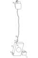
図1は、実施形態1における給電システムの構成要素を説明するための図である。実施形態1における給電システムは、電子機器100、ケーブル200、給電機器300を有
する。電子機器100、ケーブル200および給電機器300はいずれも、USB PD(Power Delivery)規格およびUSB Type-C規格に準拠する。ただし、ケーブル200は、Eマークケーブル、Eマークケーブルのふりをしたケーブル、Eマークケーブルでないケーブルのいずれかである。 [Embodiment 1]
1 is a diagram for explaining components of a power supply system in embodiment 1. The power supply system in embodiment 1 includes an
電子機器100は、給電機器300から給電される受電機器である。実施形態1では、電子機器100は、撮像装置(例えば、デジタルカメラ)として動作可能である。ただし、電子機器100は、メディアプレーヤ、スマートフォンまたはパーソナルコンピュータとして動作可能であってもよい。The
電子機器100は、撮像部102、操作部104、接続部110などを有する。電子機器100は、電池111から供給される電力により動作することができる。電子機器100における接続部110が、ケーブル200を介して給電機器300と接続することによって電力を得る。接続部110は、USB Type-Cのコネクタである。電子機器100は、電池111の電力ではなく、給電機器300からの供給電力で動作することもできる。The
給電機器300は、電子機器100に電力を供給する電子機器である。給電機器300は、ACアダプタまたはモバイルバッテリである。実施形態1では、給電機器300がSource機器であり、電子機器100がSink機器である。The
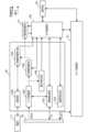
次に、図2を参照して、電子機器100の構成要素を説明する。電子機器100は、メイン制御部101、撮像部102、記録媒体103、操作部104、表示部105、メモリ106、メモリ107、サブ制御部108、電力制御部109、接続部110、電池111、電源制御部112を有する。Next, the components of the
メイン制御部101は、メモリ107に記憶されているプログラムを実行することにより、電子機器100の各構成要素を制御することができる。The
撮像部102は、レンズユニットおよび撮像素子を有し、被写体の光学像から画像データを生成する。撮像部102で生成された画像データは、メイン制御部101によって所定の画像処理が行われた後、記録媒体103に記録される。The
記録媒体103は、撮像部102から出力された画像データを記録する。記録媒体103は、電子機器100に内蔵されていてもよいし、電子機器100に対して着脱可能であってもよい。The
操作部104は、電子機器100に対するユーザの指示を受け付ける。操作部104は、メイン制御部101またはサブ制御部108に、ユーザの指示に応じた信号を通知する。操作部104は、電源ボタン(電子機器100の電源のONまたはOFFをユーザが指示するための操作部材)、レリーズスイッチ(ユーザが撮影を指示するための操作部材)、ズームレバー(ユーザが画像のズームを指示するための操作部材)などを含む。操作部104は、再生ボタン(画像データの再生をユーザが指示するための操作部材)、モードダイヤル(電子機器100の起動モードへの切り替えをユーザが指示するための操作部材)、表示部105に設けられるタッチパネルを含む。The
なお、レリーズスイッチは、第1スイッチ(SW1)と第2スイッチ(SW2)とを有する。レリーズスイッチが、いわゆる半押し状態に変化すると、第1スイッチ(SW1)がON状態に変化する。SW1がON状態に変化すると、メイン制御部101は、撮影準備を行うための指示を受け付ける。撮影準備には、AF(オートフォーカス)処理、AE
(自動露出)処理、AWB(オートホワイトバランス)処理、EF(フラッシュプリ発光)処理などが含まれる。レリーズスイッチが、いわゆる全押し状態に変化すると、第2スイッチ(SW2)がON状態に変化する。SW2がON状態に変化すると、メイン制御部101は、撮影を行うための信号(指示)を受け付ける。 The release switch has a first switch (SW1) and a second switch (SW2). When the release switch is pressed halfway, the first switch (SW1) is turned on. When SW1 is turned on, the
These include automatic exposure processing, automatic white balance processing, and pre-flash processing. When the release switch is fully pressed, a second switch (SW2) is turned on. When SW2 is turned on, the
表示部105は、撮影の際のビューファインダー画像、撮影した画像(画像データ)、対話的な操作のための文字などを表示する。なお、必ずしも電子機器100が表示部105を内蔵する必要はない。電子機器100は、内部または外部の表示部105と接続することができ、かつ、表示部105の表示を制御する表示制御部を有していればよい。The
メモリ106は、撮像部102が撮像した画像データを一時的に保持するバッファメモリである。メモリ106は、表示部105の画像表示用メモリであり、メイン制御部101の作業用メモリである。The
メモリ107は、メイン制御部101で実行されるプログラムなどを記憶する。The
サブ制御部108は、メモリに記憶されているプログラムを実行することにより、電子機器100の構成要素の一部を制御することができる。サブ制御部108は、メイン制御部101よりも低消費電力で動作可能である。サブ制御部108は、メイン制御部101と通信が可能である。The
電力制御部109は、接続部110が取得した電力を電子機器100の各構成要素に供給する。このとき、電力制御部109は、接続部110が取得した電力で電池111を充電する。The
接続部110は、給電機器300と電子機器100とを接続するインターフェースである。接続部110は、USB PD規格に準拠した機器同士が通信を行うために使用されるCC(Configuration Channel)端子を有する。電子機器100は、接続部110を用いて、給電機器300とデータの通信を行う。接続部110は、電力の通信を行うVBUS端子を有する。電子機器100は、接続部110を用いて、給電機器300から電力を取得する。The
なお、実施形態1では、電子機器100がUSB機器であり、接続部110は、USB通信をするためのインターフェースコネクタおよびUSBデバイスコントローラを含む。メイン制御部101は、接続部110を制御することで給電機器300とUSB通信を行う。In the first embodiment, the
電池111は、電子機器100を動作させるために必要な電力を供給する。電子機器100は、給電機器300の給電が停止した場合には、電池111が供給する電力によって動作する。このため、給電機器300による給電が停止しても、電子機器100は、安全に動作を継続できる。電池111は、電子機器100に対して着脱可能である。電池111は、接続部110が取得した電力を、電力制御部109を介して取得できる。これにより、電池111は充電される。電池111は、認証処理を行うCPU、RAM、ROMを含んでいる。電池111は、メイン制御部101またはサブ制御部108との間での電池認証処理を行う。電池認証処理は、電池111が所定の電池であるか否かを判定するための認証処理である。The
電源制御部112は、電子機器100の状態に基づき、電池111または電力制御部109から電子機器100の他の構成要素への電力の供給および遮断(供給の停止)を制御する。The power
次に、図3を参照して、給電機器300の構成要素を説明する。給電機器300は、メイン制御部301、接続部302、情報取得部303、接続部304、電源制御部305、出力制御部306、温度検出部307を有する。Next, the components of the
メイン制御部301は、メモリに記憶されているプログラムを実行することにより、給電機器300の各構成要素を制御する。The
接続部302は、ケーブル200を介して、電子機器100と接続するインターフェースである。接続部302は、電子機器100に電力を供給する。接続部302は、CC端子およびVBUS端子を有する。The connection unit 302 is an interface that connects to the
情報取得部303は、給電機器300のPD(Power Delivery)通信の制御をする。例えば、PD通信の制御として、情報取得部303は、給電機器300の給電能力を通知する。情報取得部303は、CC(Configuration Channel)端子を用いた通信により、電子機器100からの要求電力をネゴシエーションする(最適な値に設定する)ことができる。さらには、情報取得部303は、CC端子を用いた通信により、接続しているケーブル200(Eマークケーブル)からケーブル情報(電流容量、性能、ベンダー情報など)を取得することができる。情報取得部303は、ケーブル200がEマークケーブルであることを認証するための認証情報(証明書)をケーブル200に要求することができる。The
接続部304は、家庭用コンセントまたは電池から電力を取得する。The connection unit 304 obtains power from a household outlet or a battery.
電源制御部305は、接続部304が取得した電力を、電子機器100に供給可能な電力に変換して出力する。例えば、家庭用電源(100V,50Hzの交流電源)から電子機器100に給電(9V,3A)する場合には、電源制御部305は、電流を直流に変換して(ACDC変換をして)、電圧を9Vに変換にする。なお、電源制御部305は、メイン制御部301からの指示に従って、給電機器300の給電能力に基づき電力を変換(制御)する。このため、電源制御部305による変換後に出力可能な電圧および電流の情報が、給電機器300の給電可能な電力の情報に該当する。The power
出力制御部306は、接続部302のVBUS端子と接続する。出力制御部306は、電源制御部305から供給された電力の電子機器100への給電または遮断(給電の停止)を制御する。出力制御部306は、メイン制御部301または電子機器100からの指示に従って、給電の停止処理などを行う。The
温度検出部307は、接続部302の温度を検出して、メイン制御部301に通知する。接続部302には、金属コネクタを介してケーブル200から熱が伝導される。このため、温度検出部307は、接続部302の温度を検出することにより、ケーブル200の温度(ケーブル200の温度と同等の温度)を検出できる。The
次に、図4を参照して、電力制御部109の構成要素を説明する。電力制御部109は、情報取得部1091、入力制御部1092、給電制御部1093、充電制御部1094、接続部1095、電圧検出部1096、温度検出部1097を有する。Next, the components of the
情報取得部1091は、接続部110のCC端子に接続する。情報取得部1091は、CC端子電圧で接続している給電機器300の給電能力を検出できる。情報取得部1091は、CC端子を用いた通信によって、給電機器300に供給電力をネゴシエーションできる。さらには、CC端子を用いた通信により、情報取得部1091は、ケーブル200
のケーブル情報を取得したり、ケーブル200がEマークケーブルであることを認証するための認証情報(証明書)をケーブル200に要求したりすることができる。 The
It is possible to obtain cable information such as the E-mark cable, or to request authentication information (certificate) from the
入力制御部1092は、接続部110のVBUS端子と接続する。入力制御部1092は、VBUS端子と接続している給電機器300から電力(VBUS電力)を取得する。入力制御部1092は、情報取得部1091が取得した情報に基づくサブ制御部108からの指示に従って、給電制御部1093の電力の供給と供給の停止とを切り替える。The
給電制御部1093は、入力制御部1092を介して供給された電力(VBUS電力)の電圧を、電源制御部112および充電制御部1094が利用可能な電圧に変換する。例えば、給電制御部1093は、供給された5Vの電圧を、適正な電池電圧まで下げる。実施形態1では、電池111が1セル電池であるため、4.2Vで満充電状態となるように、定電流充電(CC充電)および定電圧充電(CV充電)が行われる。電子機器100に電池111が接続していない場合には、給電制御部1093は、電源制御部112において効率が最もよい電圧(例えば、3.7V)に、VBUS電力を変換する。The power
給電制御部1093は、給電機器300の給電能力に基づき、給電機器300の各構成要素に供給する電流を制限できる。例えば、給電機器300の給電能力が電圧9V、電流3Aである場合には、給電制御部1093は、電池111の電池電圧である4.2Vに近づくように電圧を低下させ、かつ、3A以上の電流が電源制御部112または充電制御部1094に流れないようにする。The power
充電制御部1094は、入力制御部1092および給電制御部1093を介してVBUS端子から受電する電力により、電池111を充電する。充電制御部1094は、電池111にダメージを与えないように電流を制御しながら、電池111に対してCC充電およびCV充電を行う。The charging
接続部1095には、電子機器100から取り外し可能な電池111を接続することができる。接続部1095を介して電池111に供給される電力は、電池111が有する電池セル、認証回路、サーミスタなどに供給される。A
電圧検出部1096は、入力されたVBUS電力の電圧を検出して、当該電圧の値をサブ制御部108に通知する。例えば、給電機器300の給電能力が電圧9V、電流3Aである場合には、電圧検出部1096は、給電機器300が想定以上の高い電圧(15Vなど)を出力していないか否かを検出する。または、電圧検出部1096は、電子機器100が異常状態であることに起因するショートなどが発生して、入力されるVBUS電力の電圧が9Vを大きく下回っていないか否かを検出する。このような異常な電圧が検出された場合には、サブ制御部108は、必要に応じて、入力制御部1092の動作を停止して、情報取得部1091を介して給電機器300に給電の停止を指示する。なお、図4では、電圧検出部1096は、入力制御部1092と給電制御部1093の間の電圧を検出するよう図示しているが、例えば、接続部110と接続部1095の間の電圧を検出してもよい。The
温度検出部1097は、接続部110の温度を検出(監視)して、検出した温度の値をサブ制御部108に通知する。接続部110は、金属コネクタを介してケーブル200から熱が伝導される。このため、温度検出部1097は、接続部110の温度を検出することによって、ケーブル200の温度(ケーブル200の温度と同等の温度)を検出できる。ケーブル200の温度が閾値温度Thより高い場合には、サブ制御部108は、入力制御部1092を制御して、接続部110による受電を停止する。または、サブ制御部108は、ケーブル200の温度が閾値温度Thより高い場合には、情報取得部1091を介
して給電機器300に給電の停止を指示する。 The
次に、図5のフローチャートを参照して、実施形態1における電子機器100で行われる閾値温度設定処理(電子機器100の制御方法)を説明する。なお、本フローチャートの処理は、電子機器100のサブ制御部108がプログラムを実行することにより制御される。なお、本フローチャートの開始前では、サブ制御部108が、閾値温度Thとして温度Th1を設定している。ここで、温度Th1は、電子機器100が許容できる上限温度(許容温度の上限値)である。Next, the threshold temperature setting process (control method of the electronic device 100) performed by the
ステップS501において、サブ制御部108は、接続部110に給電機器300がUSB接続されたか否かを判定する。例えば、サブ制御部108は、電圧検出部1096がVBUS電圧を検出した場合に、接続部110に給電機器300がUSB接続されたと判定してもよい。或いは、情報取得部1091のCC端子の電圧レベルに基づき、接続部110に給電機器300がUSB接続されたか否かを判定してもよい。接続部110に給電機器300がUSB接続されるまでステップS501の処理が繰り返される。接続部110に給電機器300がUSB接続された場合にはステップS502に進む。In step S501, the
ステップS502において、サブ制御部108は、閾値温度Thとして、予め定められた(予め設定された)温度Th2を設定する。ここで、温度Th2は、ケーブル200が損傷しない温度であり、一般的なケーブルの絶縁体またはシース材に使用される主な材料の許容温度における上限値である。例えば、許容温度における上限値は、エチレンポリピレンまたはポリウレタンでは90℃、ポリプロピレンでは80℃、ポリエチレンでは75℃、ビニルでは60℃である。実施形態1では、いずれの材料から形成されるケーブルであっても許容できる温度である60℃を、温度Th2としている。このため、閾値温度Thが温度Th2であれば、サブ制御部108は、ケーブルが損傷する温度に到達する前に、給電機器300による給電を抑制することができる。In step S502, the
ステップS503において、情報取得部1091は、給電機器300によって供給可能な電圧値および電流値の組み合わせの電力リストを情報取得部303から受信したか否かを判定する。電力リストを情報取得部303から受信した場合にはステップS506に進み、電力リストを情報取得部303から受信しなかった場合にはステップS504に進む。In step S503, the
ステップS504において、情報取得部1091は、情報取得部1091が電力リストを受信するまでにタイムアウトしたか否かを判定する。例えば、電子機器100は、620ms経過しても電力リストが送信されない場合に、情報取得部1091を介して情報取得部303にリセット信号を送る。ここで、適切なケーブル200によって正常に電子機器100と給電機器300とが接続されていれば、リセット信号を取得した情報取得部303から電力リストが送信される。そして、620ms待機してからリセット信号を送信することを情報取得部1091が3回繰り返しても電力リストを受信できない場合に、タイムアウトする。情報取得部1091が電力リストを受信するまでにタイムアウトした場合にはステップS505に進み、情報取得部1091が電力リストを受信するまでにタイムアウトしなかった場合にはステップS503に進む。In step S504, the
ステップS505において、サブ制御部108は、給電制御部1093を制御して、接続部110が受電した電力を、情報取得部1091のCC端子電圧によって判定された給電機器300の給電能力以下にするように変電する。In step S505, the
ステップS506において、情報取得部1091は、給電機器300とPD通信を行い、給電機器300の供給電力を決定する。In step S506, the
ステップS507において、情報取得部1091は、VCONN_Swapを要求して、ケーブル情報の取得を試みる。VCONN_Swapの要求は、Sourceとしての役割とSinkとしての役割とを交換する要求であり、ケーブル200に電力を供給する権利を求める要求である。VCONN_Swapを要求し、VCONN_Swapが許可されれば、Sinkとなった電子機器は、VCONN_Sourceとなることができる。Sinkとなった電子機器は、VCONN_SwapによりVCONN_Sourceとなることができれば、ケーブル200からケーブル情報を取得できる。ケーブル情報は、例えば、最高動作温度(Maximum Operating Temperature)を含む。最高動作温度は、USB Power Delivery Revision 3.0 Active Cable VDO2に含まれる項目である。In step S507, the
ステップS508において、サブ制御部108は、情報取得部1091がケーブル200のケーブル情報を取得できたか否かを判定する。情報取得部1091がケーブル200のケーブル情報を取得できた場合にはステップS509に進む。情報取得部1091がケーブル200のケーブル情報を取得できなかった場合には、本フローチャートは終了するため、サブ制御部108は、閾値温度Thを温度Th2から変更しない。In step S508, the
ステップS509において、サブ制御部108は、閾値温度Thを温度Th2から変更するか否かを判定する。サブ制御部108は、ケーブル情報に基づく(ケーブル情報が示す)温度Th3が、予め定められた温度Th2よりも高い場合に、閾値温度Thを温度Th3に変更すると判定する。ここで、温度Th3は、例えば、ケーブル情報が示す最高動作温度である。閾値温度Thを温度Th2から変更する場合にはステップS510に進み、閾値温度Thを温度Th2から変更しない場合には本フローチャートは終了する。In step S509, the
ステップS510において、サブ制御部108は、閾値温度Thを温度Th2から温度Th3に変更する。このため、例えば、サブ制御部108は、温度Th2と温度Th3とのうちの高い方の温度を閾値温度Thとすることができる。温度Th2と温度Th3とのうちの高い方の温度が閾値温度Thであることによれば、ケーブル200の温度を必要以上に制限しないため、給電(受電)が停止する可能性が低減できる。このため、ケーブル200、電子機器100および給電機器300の安全性と、給電の安定性とを両立することができる。In step S510, the
なお、最大限に電子機器100およびケーブル200の安全を図るために、サブ制御部108が、温度Th2と温度Th3とのうちの低い方の温度を閾値温度Thとしてもよい。温度Th3が温度Th1よりも高い場合には、温度Th2と温度Th3の大小関係によらず、サブ制御部108は、閾値温度Thを温度Th1に変更してもよい。これによれば、電子機器100の許容温度である温度Th1よりもケーブル200が熱くなることを防止することができる。To maximize the safety of the
このように、サブ制御部108は、閾値温度Thを超える温度を検出した場合に、接続部110による受電の停止(入力制御部1092の動作の停止)をする。または/さらに、サブ制御部108は、閾値温度Thを超える温度を検出した場合に、情報取得部1091を介して給電機器300に給電の停止を指示する。これにより、ケーブル200の温度が許容温度以上に変化することを防止できるため、ケーブル200、給電機器300および電子機器100の安全性が向上する。In this way, when the
なお、閾値温度Thを超える温度を検出した場合のサブ制御部108の処理は、電子機器100の受電の停止または/および給電機器300の給電の停止に限られない。サブ制御部108は、閾値温度Thを超える温度を検出した場合に、そうでない場合よりも、電
子機器100が取得する電力が低下するように制御すればよい。これによっても、ケーブル200における温度上昇を抑制できるため、ケーブル200および電子機器100の安全性が向上する。 Note that the process of the
[実施形態2]
以下では、実施形態2を説明する。なお、実施形態2における電子機器100および給電機器300の構成要素は、実施形態1における電子機器100および給電機器300の構成要素と同様であるため、それらの詳細な説明を省略する。 [Embodiment 2]
Hereinafter, a description will be given of the second embodiment. Note that components of the
図6のフローチャートを参照して、実施形態2における電子機器100で行われる閾値温度設定処理を説明する。なお、本フローチャートの処理は、サブ制御部108がプログラムを実行することにより制御される。なお、ステップS501~ステップS510の処理は、実施形態1におけるステップS501~ステップS510の処理と同じであるため、それらの説明を省略する。本フローチャートの開始前では、サブ制御部108は、実施形態1と同様に、閾値温度Thとして温度Th1を設定している。The threshold temperature setting process performed by the
ステップS621において、情報取得部1091は、VCONN_Swapを要求することにより、ケーブル200の認証情報の取得を試みる。VCONN_Swapの要求が認められれば、情報取得部1091は、ケーブル200の認証情報を取得することができる。認証情報の取得には、USB Type-C Authentication Specification Revision 1.0に準拠した認証方法を用いることができる。In step S621, the
ステップS622において、サブ制御部108は、情報取得部1091がケーブル200の認証情報を取得できたか否かを判定する。情報取得部1091がケーブル200の認証情報が取得できた場合にはステップ507に進み、情報取得部1091がケーブル200の認証情報が取得できなかった場合には本フローチャートは終了する。このため、ケーブル200の認証情報が取得されていない場合には、サブ制御部108は、ケーブル200のケーブル情報にかかわらず、閾値温度Thを温度Th2から変更しない。In step S622, the
なお、実施形態2では、電子機器100は、ステップS622においてケーブル200の認証情報を取得した場合に、ステップS507においてケーブル200のケーブル情報の取得を試みる。しかし、電子機器100は、ステップS622より前のステップで、ケーブル200のケーブル情報の取得を試みてもよい。この場合には、サブ制御部108は、ステップS622でケーブルの認証情報を取得していなければ、ケーブル200のケーブル情報を参照せずに、閾値温度Thを温度Th2から変更しない。In the second embodiment, if the
このように、サブ制御部108は、温度検出部1097が閾値温度Thを超える温度を検出した場合に、入力制御部1092の動作を停止して、情報取得部1091を介して給電機器300に出力停止(給電停止)を指示する。これにより、ケーブルの温度が許容温度以上になることを防ぐことができるため、ケーブルおよび電子機器の安全性が向上する。In this way, when the
実施形態2では、電子機器100は、ケーブル200から認証情報を取得できない場合(ケーブル200がEマークケーブルであることを認証できない場合)には、閾値温度Thを温度Th2から変更しない。これにより、ケーブル200がEマークケーブルでなかったとしても、電子機器100が閾値温度Thを誤った温度に変更してしまうことを防ぐことができる。このため、ケーブル200、給電機器300および電子機器100の安全性がより向上する。In the second embodiment, if the
[実施形態3]
実施形態1または2では、電子機器100が、ケーブル200の温度が閾値温度Thを超える場合に、給電機器300による給電などを停止するように制御する例を説明した。実施形態3では、給電機器300が、ケーブル200の温度が閾値温度Thを超える場合に、電子機器100への給電などを停止する例を説明する。なお、実施形態3における電子機器100および給電機器300の構成要素は、実施形態1における電子機器100および給電機器300の構成の構成要素と同様であるため、それらの詳細な説明を省略する。 [Embodiment 3]
In the first or second embodiment, an example is described in which the
実施形態3では、メイン制御部301は、温度検出部307が閾値温度Thを超える温度を検出した場合に、出力制御部306に給電の停止を指示する。或いは、メイン制御部301は、温度検出部307が閾値温度Thを超える温度を検出した場合に、情報取得部303を介して電子機器100に受電の停止を指示する。In the third embodiment, when the
以下、図7のフローチャートを参照して、実施形態3における給電機器300で行われる閾値温度設定処理を説明する。なお、本フローチャートの処理は、メイン制御部301がプログラムを実行することにより制御される。本フローチャートの開始前には、メイン制御部301は、閾値温度Thとして温度Th1を設定している。温度Th1は、給電機器300が許容できる上限温度(許容温度の上限値)である。The threshold temperature setting process performed by the
ステップS701において、メイン制御部301は、接続部302に電子機器100がUSB接続されたか否かを判定する。例えば、給電機器300は、情報取得部303のCC端子の電圧レベルに基づき、接続部302に電子機器100がUSB接続されたか否かを判定する。接続部302に電子機器100がUSB接続されるまでステップS701の処理が繰り返される。接続部302に電子機器100がUSB接続された場合にはステップS702に進む。In step S701, the
ステップS702において、ステップS502と同様に、メイン制御部301は、閾値温度Thとして温度Th2を設定する。温度Th2は、ケーブル200が損傷しない温度であり、一般的なケーブルの絶縁体またはシース材に使用される主な材料の許容温度における上限値である。In step S702, similar to step S502, the
ステップS703において、情報取得部303は、要求する電力を示す情報(要求電力情報)を情報取得部1091から受信したか否かを判定する。情報取得部1091から要求電力情報を受信した場合にはステップS706に進み、そうでない場合にはステップS704に進む。In step S703, the
ステップS704において、情報取得部303は、要求電力情報を受信するまでにタイムアウトしたか否かを判定する。所定の時間が経過するまでに、情報取得部1091から要求電力情報が送信されていなければ、タイムアウトする。情報取得部303が要求電力情報を受信するまでにタイムアウトした場合にはステップS705に進み、そうでない場合にはステップS703に進む。In step S704, the
ステップS705において、メイン制御部301は、情報取得部303のCC端子電圧によって電子機器100に提示した給電能力に、供給する電力を変電するように出力制御部306を制御する。In step S705, the
ステップS706において、情報取得部303は、情報取得部1091とPD通信を行い、電子機器100への供給電力を決定する。In step S706, the
ステップS707において、情報取得部303は、ケーブル200の認証情報の取得を試行する。例えば、情報取得部303は、USB Type-C Authentication Specification Revision 1.0に準拠した認証方法により認証情報を取得することを試行する。In step S707, the
ステップS708において、メイン制御部301は、情報取得部303がケーブル200の認証情報を取得できたか否かを判定する。情報取得部303がケーブル200の認証情報を取得できた場合にはステップS709に進み、情報取得部303がケーブル200の認証情報を取得できなかった場合には本フローチャートは終了する。このため、情報取得部303がケーブル200の認証情報を取得できなかった場合、メイン制御部301は、閾値温度Thを温度Th2から変更しない。In step S708, the
ステップS709において、情報取得部303は、ケーブル200のケーブル情報を取得するように試行する。In step S709, the
ステップS710において、メイン制御部301は、情報取得部303がケーブル情報を取得できたか否かを判定する。情報取得部303がケーブル情報を取得できた場合にはステップS711に進み、情報取得部303がケーブル情報を取得できなかった場合には本フローチャートは終了する。このため、情報取得部303がケーブル情報を取得できなかった場合、メイン制御部301は、閾値温度Thを温度Th2から変更しない。In step S710, the
ステップS711において、メイン制御部301は、閾値温度Thを温度Th2から変更するか否かを判定する。例えば、メイン制御部301は、ケーブル情報に基づく温度Th3が温度Th2よりも高い場合には、閾値温度Thを温度Th2から温度Th3に変更すると判定する。閾値温度Thを変更する場合にはステップS712に進み、閾値温度Thを変更しない場合にはフローチャートが終了する。In step S711, the
ステップS712において、メイン制御部301は、ステップS510と同様に、閾値温度Thを温度Th2から変更する。例えば、温度Th3が温度Th2よりも高い場合には、メイン制御部301は、閾値温度Thを温度Th3に変更することができる。例えば、温度Th3が温度Th1よりも高い場合には、メイン制御部301は、閾値温度Thを温度Th1に変更することができる。In step S712, the
このように、メイン制御部301は、温度検出部307が閾値温度Thを超える温度を検出した場合に、出力制御部306の給電停止を指示する。或いは、メイン制御部301は、情報取得部303を介して、電子機器100に受電停止を指示する。これにより、ケーブル200の温度が許容温度以上に変化することを防止できるため、ケーブル200、電子機器100、給電機器300の安全性が向上する。In this way, when the
[実施形態4]
上述の実施形態で説明した様々な機能、処理及び方法は、パーソナルコンピュータ、マイクロコンピュータ、CPU(Central Processing Unit)などがプログラムを用いて実現することもできる。以下、実施形態4では、パーソナルコンピュータ、マイクロコンピュータ、CPUなどを「コンピュータX」と呼ぶ。実施形態4では、コンピュータXを制御するためのプログラムであって、上述の実施形態で説明した様々な機能、処理及び方法を実現するためのプログラムを「プログラムY」と呼ぶ。 [Embodiment 4]
The various functions, processes, and methods described in the above embodiments can also be realized by a personal computer, a microcomputer, a CPU (Central Processing Unit), etc. using a program. Hereinafter, in the fourth embodiment, the personal computer, the microcomputer, the CPU, etc. are referred to as "computer X." In the fourth embodiment, a program for controlling computer X and for realizing the various functions, processes, and methods described in the above embodiments is referred to as "program Y."
上述の実施形態で説明した様々な機能、処理及び方法は、コンピュータXがプログラムYを実行することによって実現される。この場合において、プログラムYは、コンピュータ読み取り可能な記憶媒体を介してコンピュータXに供給される。実施形態4におけるコ
ンピュータ読み取り可能な記憶媒体は、ハードディスク装置、磁気記憶装置、光記憶装置、光磁気記憶装置、メモリカード、揮発性メモリ、不揮発性メモリなどの少なくとも一つを含む。実施形態4におけるコンピュータ読み取り可能な記憶媒体は、non-transitory(非一時的)な記憶媒体である。 The various functions, processes, and methods described in the above embodiments are realized by computer X executing program Y. In this case, program Y is supplied to computer X via a computer-readable storage medium. The computer-readable storage medium in embodiment 4 includes at least one of a hard disk device, a magnetic storage device, an optical storage device, a magneto-optical storage device, a memory card, a volatile memory, a non-volatile memory, and the like. The computer-readable storage medium in embodiment 4 is a non-transitory storage medium.
100:電子機器、108:サブ制御部、110:接続部、1097:温度検出部、
200:ケーブル、300:給電機器100: electronic device, 108: sub-control unit, 110: connection unit, 1097: temperature detection unit,
200: Cable, 300: Power supply device
Claims (16)
Translated fromJapaneseケーブルを介して給電機器から受電することが可能な接続手段と、
前記電子機器に接続された前記ケーブルの温度を検出する検出手段と、
前記電子機器に接続された前記ケーブルから、前記ケーブルに関連した情報を含むケーブル情報を受信する通信手段と、
前記検出手段により検出された前記ケーブルの温度が閾値温度より高い場合に、前記給電機器から前記ケーブルを介して前記電子機器に給電するのを停止させるように前記給電機器を制御する、または、前記給電機器から前記ケーブルを介して電力を受けるのを停止するように前記電子機器を制御する制御手段とを有し、
前記制御手段は、前記通信手段により前記ケーブル情報が受信され、前記ケーブル情報に基づく第3の温度が予め設定された第2の温度よりも高い場合に、前記閾値温度を前記第3の温度に設定することを特徴とする電子機器。An electronic device,
A connection means capable of receiving power from a power supply device via a cable;
a detection means for detecting a temperature of the cableconnected to the electronic device ;
Acommunication means forreceiving cable information from the cableconnected to the electronic device ,the cable information including information related to the cable ;
a control means for controlling the power supply device to stop power supply from the power supply device through the cable to the electronic device when the temperature of the cable detected by the detection means is higher than a threshold temperature, or for controlling the electronic device to stop receiving power from the power supply device through the cable,
The electronic device is characterized in that the control meanssets the threshold temperature to thethird temperature when the cableinformation is received by the communication means and a third temperature based on the cable information is higher than a predetermined second temperature.
ケーブルを介して受電機器に給電することが可能な接続手段と、A connection means capable of supplying power to a power receiving device via a cable;
前記電子機器に接続された前記ケーブルの温度を検出する検出手段と、a detection means for detecting a temperature of the cable connected to the electronic device;
前記電子機器に接続された前記ケーブルから、前記ケーブルに関連した情報を含むケーブル情報を受信する通信手段と、A communication means for receiving cable information from the cable connected to the electronic device, the cable information including information related to the cable;
前記検出手段により検出された前記ケーブルの温度が閾値温度より高い場合に、前記受電機器が前記電子機器から前記ケーブルを介して電力を受けるのを停止するように前記受電機器を制御する、または、前記ケーブルを介して前記受電機器に給電するのを停止するように前記電子機器を制御する制御手段とを有し、a control means for controlling the power receiving device so as to stop the power receiving device from the electronic device through the cable, or for controlling the electronic device so as to stop supplying power to the power receiving device through the cable, when the temperature of the cable detected by the detection means is higher than a threshold temperature;
前記制御手段は、前記通信手段により前記ケーブル情報が受信され、前記ケーブル情報に基づく第3の温度が予め設定された第2の温度よりも高い場合に、前記閾値温度を前記第3の温度に設定することを特徴とする電子機器。The electronic device is characterized in that the control means sets the threshold temperature to the third temperature when the cable information is received by the communication means and a third temperature based on the cable information is higher than a predetermined second temperature.
前記電子機器に前記ケーブルが接続されたことが検出された場合に、前記閾値温度を前記第2の温度に設定し、setting the threshold temperature to the second temperature when it is detected that the cable is connected to the electronic device;
前記通信手段により前記ケーブル情報が受信され、前記ケーブル情報が示す前記第3のThe cable information is received by the communication means, and the third
温度が前記第2の温度よりも高い場合に、前記閾値温度を前記第2の温度から前記第3の温度に変更することを特徴とする請求項1または2に記載の電子機器。3. The electronic device according to claim 1, wherein, when a temperature is higher than the second temperature, the threshold temperature is changed from the second temperature to the third temperature.
前記電子機器に接続された前記ケーブルの温度を検出する検出ステップと、
前記電子機器に接続された前記ケーブルから、前記ケーブルに関連した情報を含むケーブル情報を受信する通信ステップと、
前記検出ステップにおいて検出された前記ケーブルの温度が閾値温度より高い場合に、前記給電機器から前記ケーブルを介して前記電子機器に給電するのを停止させるように前記給電機器を制御する、または、前記給電機器から前記ケーブルを介して電力を受けるのを停止するように前記電子機器を制御する制御ステップとを有し、
前記制御ステップでは、前記通信ステップにおいて前記ケーブル情報が受信され、前記ケーブル情報に基づく第3の温度が予め設定された第2の温度よりも高い場合に、前記閾値温度を前記第3の温度に設定することを特徴とする制御方法。 A method for controlling an electronic device having a connection means capable of receiving power from a power supply device via a cable, comprising:
a detection step of detecting a temperature of the cableconnected to the electronic device ;
acommunication step ofreceiving cable information from the cableconnected to the electronic device ,the cable information including information related to the cable ;
a control step of controlling the power supply device to stop power supply from the power supply device through the cable to the electronic device when the temperature of the cable detected in the detection step is higher than a threshold temperature, or controlling the electronic device to stop receiving power from the power supply device through the cable;
A control method characterized in that, in the control step, the cable information is received in the communication step, and whena third temperature based on the cable informationishigher than a predetermined second temperature, the threshold temperature is set to the third temperature .
前記電子機器に接続された前記ケーブルの温度を検出する検出ステップと、
前記電子機器に接続された前記ケーブルから、前記ケーブルに関連した情報を含むケーブル情報を受信する通信ステップと、
前記検出ステップにおいて検出された前記ケーブルの温度が閾値温度より高い場合に、前記受電機器が前記電子機器から前記ケーブルを介して電力を受けるのを停止するように前記受電機器を制御する、または、前記ケーブルを介して前記受電機器に給電するのを停止するように前記電子機器を制御する制御ステップとを有し、
前記制御ステップでは、前記通信ステップにおいて前記ケーブル情報が受信され、前記ケーブル情報に基づく第3の温度が予め設定された第2の温度よりも高い場合に、前記閾値温度を前記第3の温度に設定することを特徴とする制御方法。 A method for controlling an electronic device having a connection means capable of supplying power to a power receiving device via a cable, comprising:
a detection step of detecting a temperature of the cableconnected to the electronic device ;
acommunication step ofreceiving cable information from the cableconnected to the electronic device ,the cable information including information related to the cable ;
a control step of controlling the power receiving device so as to stop the power receiving device from the electronic device through the cable, or controlling the electronic device so as to stop supplying power to the power receiving device through the cable, when the temperature of the cable detected in the detection step is higher than a threshold temperature;
A control method characterized in that, in the control step, the cable information is received in the communication step, and whena third temperature based on the cable informationishigher than a predetermined second temperature, the threshold temperature is set to the third temperature .
前記電子機器に接続された前記ケーブルの温度を検出する検出ステップと、
前記電子機器に接続された前記ケーブルから、前記ケーブルに関連した情報を含むケーブル情報を受信する通信ステップと、
前記検出ステップにおいて検出された前記ケーブルの温度が閾値温度より高い場合に、前記給電機器から前記ケーブルを介して前記電子機器に給電するのを停止させるように前記給電機器を制御する、または、前記給電機器から前記ケーブルを介して電力を受けるのを停止するように前記電子機器を制御する制御ステップと、
を実行させ、
前記制御ステップでは、前記通信ステップにおいて前記ケーブル情報が受信され、前記ケーブル情報に基づく第3の温度が予め設定された第2の温度よりも高い場合に、前記閾値温度を前記第3の温度に設定することを実行させるためのプログラム。 A computer of an electronic device having a connection means capable of receiving power from a power supply device via a cable,
a detection step of detecting a temperature of the cableconnected to the electronic device ;
acommunication step ofreceiving cable information from the cableconnected to the electronic device ,the cable information including information related to the cable ;
a control step of controlling the power supply device to stop power supply from the power supply device through the cable to the electronic device, or controlling the electronic device to stop receiving power from the power supply device through the cable, when the temperature of the cable detected in the detection step is higher than a threshold temperature;
Run the command,
In the control step, a program for executing the process of setting the threshold temperature to the third temperature when the cable information is received in the communication step and athirdtemperature based on the cable informationis higher than a predetermined second temperature.
前記電子機器に接続された前記ケーブルの温度を検出する検出ステップと、
前記電子機器に接続された前記ケーブルから、前記ケーブルに関連した情報を含むケーブル情報を受信する通信ステップと、
前記検出ステップにおいて検出された前記ケーブルの温度が閾値温度より高い場合に、前記受電機器が前記電子機器から前記ケーブルを介して電力を受けるのを停止するように前記受電機器を制御する、または、前記ケーブルを介して前記受電機器に給電するのを停止するように前記電子機器を制御する制御ステップと、
を実行させ、
前記制御ステップでは、前記通信ステップにおいて前記ケーブル情報が受信され、前記ケーブル情報に基づく第3の温度が予め設定された第2の温度よりも高い場合に、前記閾値温度を前記第3の温度に設定することを実行させるためのプログラム。 A computer of an electronic device having a connection means capable of supplying power to a power receiving device via a cable,
a detection step of detecting a temperature of the cableconnected to the electronic device ;
acommunication step ofreceiving cable information from the cableconnected to the electronic device ,the cable information including information related to the cable ;
a control step of controlling the power receiving device so as to stop the power receiving device from receiving power through the cable from the electronic device, or controlling the electronic device so as to stop supplying power to the power receiving device through the cable, when the temperature of the cable detected in the detection step is higher than a threshold temperature;
Run the command,
In the control step, a program for executing the process of settingthe threshold temperature to the third temperature when the cable information is received in the communication step and a third temperature based on the cable information is higher than a predetermined second temperature.
Priority Applications (4)
| Application Number | Priority Date | Filing Date | Title |
|---|---|---|---|
| JP2020134685AJP7547112B2 (en) | 2020-08-07 | 2020-08-07 | Electronic device, control method, and program |
| US17/444,412US11703926B2 (en) | 2020-08-07 | 2021-08-04 | Electronic device and method |
| EP21189777.2AEP3998520B1 (en) | 2020-08-07 | 2021-08-05 | Electronic device, method, and program |
| CN202110896887.7ACN114069558B (en) | 2020-08-07 | 2021-08-05 | Electronic device, control method thereof, and non-transitory computer-readable storage medium |
Applications Claiming Priority (1)
| Application Number | Priority Date | Filing Date | Title |
|---|---|---|---|
| JP2020134685AJP7547112B2 (en) | 2020-08-07 | 2020-08-07 | Electronic device, control method, and program |
Publications (3)
| Publication Number | Publication Date |
|---|---|
| JP2022030577A JP2022030577A (en) | 2022-02-18 |
| JP2022030577A5 JP2022030577A5 (en) | 2023-08-08 |
| JP7547112B2true JP7547112B2 (en) | 2024-09-09 |
Family
ID=77518895
Family Applications (1)
| Application Number | Title | Priority Date | Filing Date |
|---|---|---|---|
| JP2020134685AActiveJP7547112B2 (en) | 2020-08-07 | 2020-08-07 | Electronic device, control method, and program |
Country Status (4)
| Country | Link |
|---|---|
| US (1) | US11703926B2 (en) |
| EP (1) | EP3998520B1 (en) |
| JP (1) | JP7547112B2 (en) |
| CN (1) | CN114069558B (en) |
Citations (3)
| Publication number | Priority date | Publication date | Assignee | Title |
|---|---|---|---|---|
| JP2017038429A (en) | 2015-08-07 | 2017-02-16 | ルネサスエレクトロニクス株式会社 | Power supply system and power supply control method |
| JP2018057103A (en) | 2016-09-27 | 2018-04-05 | ルネサスエレクトロニクス株式会社 | Power supply system and negotiation controller |
| JP2020005339A (en) | 2018-06-25 | 2020-01-09 | キヤノン株式会社 | Electronic device and control method for electronic device |
Family Cites Families (20)
| Publication number | Priority date | Publication date | Assignee | Title |
|---|---|---|---|---|
| US5424895A (en)* | 1993-08-17 | 1995-06-13 | Gaston; William R. | Electrical wiring system with overtemperature protection |
| JP6288913B2 (en) | 2012-12-28 | 2018-03-07 | キヤノン株式会社 | Electronic device and program |
| CN104756340A (en)* | 2013-10-24 | 2015-07-01 | 三洋电机株式会社 | Electrical cable and power supply device |
| US9806515B2 (en)* | 2013-12-24 | 2017-10-31 | Nokia Technologies Oy | Protection of cables and connectors |
| JP6412420B2 (en) | 2014-12-05 | 2018-10-24 | キヤノン株式会社 | Electronic device, control method and program |
| ES2770655T3 (en)* | 2015-03-27 | 2020-07-02 | Guangdong Oppo Mobile Telecommunications Corp Ltd | Electric power management procedure and apparatus and electronic device |
| CN108767346B (en)* | 2015-03-27 | 2020-03-17 | Oppo广东移动通信有限公司 | Charging control method and device and charging cable |
| WO2016172879A1 (en)* | 2015-04-29 | 2016-11-03 | 广东欧珀移动通信有限公司 | Method for identifying types of cables, power adaptor and cable |
| US9912142B2 (en)* | 2015-04-30 | 2018-03-06 | Dialog Semiconductor, Inc. | Cable protection device |
| JP6643035B2 (en) | 2015-10-09 | 2020-02-12 | キヤノン株式会社 | Electronic equipment, control method and program |
| US11101633B2 (en)* | 2015-10-16 | 2021-08-24 | Frederick M. Foster | Circuit protection system and method |
| GB2552447B (en)* | 2016-04-06 | 2019-06-12 | Qhi Group Ltd | Fault monitoring systems and methods for detecting connectivity faults |
| JP6779678B2 (en) | 2016-07-04 | 2020-11-04 | キヤノン株式会社 | Information processing equipment, information processing methods and programs |
| JP6877901B2 (en) | 2016-07-04 | 2021-05-26 | キヤノン株式会社 | Information processing equipment, information processing methods and programs |
| US10372568B2 (en) | 2016-07-20 | 2019-08-06 | Canon Kabushiki Kaisha | Electronic device being connectable to external device, and method of controlling electronic device being connectable to extenal device |
| JP6792389B2 (en) | 2016-09-16 | 2020-11-25 | キヤノン株式会社 | Electronic devices and control methods for electronic devices |
| US10670476B2 (en)* | 2016-11-04 | 2020-06-02 | Infineon Technologies Ag | Temperature sensing for USB Type-C cables |
| US10630091B2 (en)* | 2016-11-15 | 2020-04-21 | Huawei Technologies Co., Ltd. | Charging method and related device |
| US11152807B2 (en) | 2018-04-06 | 2021-10-19 | Stmicroelectronics (Grenoble 2) Sas | Method for selecting a supply source power |
| JP7256646B2 (en) | 2018-04-11 | 2023-04-12 | キヤノン株式会社 | Electronic device and control method and program for electronic device |
- 2020
- 2020-08-07JPJP2020134685Apatent/JP7547112B2/enactiveActive
- 2021
- 2021-08-04USUS17/444,412patent/US11703926B2/enactiveActive
- 2021-08-05EPEP21189777.2Apatent/EP3998520B1/enactiveActive
- 2021-08-05CNCN202110896887.7Apatent/CN114069558B/enactiveActive
Patent Citations (3)
| Publication number | Priority date | Publication date | Assignee | Title |
|---|---|---|---|---|
| JP2017038429A (en) | 2015-08-07 | 2017-02-16 | ルネサスエレクトロニクス株式会社 | Power supply system and power supply control method |
| JP2018057103A (en) | 2016-09-27 | 2018-04-05 | ルネサスエレクトロニクス株式会社 | Power supply system and negotiation controller |
| JP2020005339A (en) | 2018-06-25 | 2020-01-09 | キヤノン株式会社 | Electronic device and control method for electronic device |
Also Published As
| Publication number | Publication date |
|---|---|
| JP2022030577A (en) | 2022-02-18 |
| CN114069558A (en) | 2022-02-18 |
| US20220043495A1 (en) | 2022-02-10 |
| EP3998520B1 (en) | 2024-04-10 |
| CN114069558B (en) | 2025-04-25 |
| EP3998520A1 (en) | 2022-05-18 |
| US11703926B2 (en) | 2023-07-18 |
Similar Documents
| Publication | Publication Date | Title |
|---|---|---|
| JP7328055B2 (en) | ELECTRONIC DEVICE AND METHOD OF CONTROLLING ELECTRONIC DEVICE | |
| US11720156B2 (en) | Electronic device | |
| JP7256646B2 (en) | Electronic device and control method and program for electronic device | |
| US9395781B2 (en) | Electronic device to perform enumeration without power request to an external device when electronic device is on | |
| JP2017073096A (en) | Electronic appliance and program | |
| JP7130373B2 (en) | Imaging device | |
| JP2019121111A (en) | Electronic apparatus, control method and program | |
| JP7545304B2 (en) | Electronic device and control method | |
| JP2019154210A (en) | Electronic device, control method of the same, and program | |
| JP7515314B2 (en) | Electronic device and control method | |
| US11599130B2 (en) | Power receiving apparatus and control method | |
| JP7547112B2 (en) | Electronic device, control method, and program | |
| US12032422B2 (en) | Power supplying apparatus that supplies power to external apparatus based on power flow information and the role of the power supplying apparatus and a method of controlling the same | |
| JP2022063616A (en) | Power supply apparatus, method for control, and program | |
| JP7483482B2 (en) | Electronic device, control method, and program | |
| JP2023091501A (en) | IMAGING DEVICE, CONTROL METHOD AND PROGRAM | |
| US20240089587A1 (en) | Electronic apparatus, control method for electronic apparatus, and non-transitory computer readable medium | |
| JP2020182359A (en) | Electronics, control methods and programs | |
| JP2025093725A (en) | Electronic device, control method, and program | |
| JP2017102762A (en) | Power supply | |
| JP2024119022A (en) | Electronic device, control method, and program | |
| JP2023049774A (en) | Electronic device, control method and program |
Legal Events
| Date | Code | Title | Description |
|---|---|---|---|
| A521 | Request for written amendment filed | Free format text:JAPANESE INTERMEDIATE CODE: A523 Effective date:20230731 | |
| A621 | Written request for application examination | Free format text:JAPANESE INTERMEDIATE CODE: A621 Effective date:20230731 | |
| TRDD | Decision of grant or rejection written | ||
| A01 | Written decision to grant a patent or to grant a registration (utility model) | Free format text:JAPANESE INTERMEDIATE CODE: A01 Effective date:20240730 | |
| A977 | Report on retrieval | Free format text:JAPANESE INTERMEDIATE CODE: A971007 Effective date:20240731 | |
| A61 | First payment of annual fees (during grant procedure) | Free format text:JAPANESE INTERMEDIATE CODE: A61 Effective date:20240828 | |
| R150 | Certificate of patent or registration of utility model | Ref document number:7547112 Country of ref document:JP Free format text:JAPANESE INTERMEDIATE CODE: R150 |