JP7546470B2 - Agricultural machinery - Google Patents
Agricultural machineryDownload PDFInfo
- Publication number
- JP7546470B2 JP7546470B2JP2020205187AJP2020205187AJP7546470B2JP 7546470 B2JP7546470 B2JP 7546470B2JP 2020205187 AJP2020205187 AJP 2020205187AJP 2020205187 AJP2020205187 AJP 2020205187AJP 7546470 B2JP7546470 B2JP 7546470B2
- Authority
- JP
- Japan
- Prior art keywords
- field
- unit
- detection
- area
- detection unit
- Prior art date
- Legal status (The legal status is an assumption and is not a legal conclusion. Google has not performed a legal analysis and makes no representation as to the accuracy of the status listed.)
- Active
Links
Images


Classifications
- A—HUMAN NECESSITIES
- A01—AGRICULTURE; FORESTRY; ANIMAL HUSBANDRY; HUNTING; TRAPPING; FISHING
- A01B—SOIL WORKING IN AGRICULTURE OR FORESTRY; PARTS, DETAILS, OR ACCESSORIES OF AGRICULTURAL MACHINES OR IMPLEMENTS, IN GENERAL
- A01B69/00—Steering of agricultural machines or implements; Guiding agricultural machines or implements on a desired track
- A—HUMAN NECESSITIES
- A01—AGRICULTURE; FORESTRY; ANIMAL HUSBANDRY; HUNTING; TRAPPING; FISHING
- A01D—HARVESTING; MOWING
- A01D34/00—Mowers; Mowing apparatus of harvesters
- A01D34/01—Mowers; Mowing apparatus of harvesters characterised by features relating to the type of cutting apparatus
- A01D34/02—Mowers; Mowing apparatus of harvesters characterised by features relating to the type of cutting apparatus having reciprocating cutters
- A01D34/24—Lifting devices for the cutter-bar
- A—HUMAN NECESSITIES
- A01—AGRICULTURE; FORESTRY; ANIMAL HUSBANDRY; HUNTING; TRAPPING; FISHING
- A01D—HARVESTING; MOWING
- A01D41/00—Combines, i.e. harvesters or mowers combined with threshing devices
- A01D41/12—Details of combines
- A01D41/127—Control or measuring arrangements specially adapted for combines
- G—PHYSICS
- G05—CONTROLLING; REGULATING
- G05D—SYSTEMS FOR CONTROLLING OR REGULATING NON-ELECTRIC VARIABLES
- G05D1/00—Control of position, course, altitude or attitude of land, water, air or space vehicles, e.g. using automatic pilots
- G05D1/20—Control system inputs
- G05D1/24—Arrangements for determining position or orientation
- G05D1/243—Means capturing signals occurring naturally from the environment, e.g. ambient optical, acoustic, gravitational or magnetic signals
- G—PHYSICS
- G05—CONTROLLING; REGULATING
- G05D—SYSTEMS FOR CONTROLLING OR REGULATING NON-ELECTRIC VARIABLES
- G05D1/00—Control of position, course, altitude or attitude of land, water, air or space vehicles, e.g. using automatic pilots
- G05D1/20—Control system inputs
- G05D1/24—Arrangements for determining position or orientation
- G05D1/246—Arrangements for determining position or orientation using environment maps, e.g. simultaneous localisation and mapping [SLAM]
- G—PHYSICS
- G05—CONTROLLING; REGULATING
- G05D—SYSTEMS FOR CONTROLLING OR REGULATING NON-ELECTRIC VARIABLES
- G05D1/00—Control of position, course, altitude or attitude of land, water, air or space vehicles, e.g. using automatic pilots
- G05D1/40—Control within particular dimensions
- G05D1/43—Control of position or course in two dimensions
- G—PHYSICS
- G05—CONTROLLING; REGULATING
- G05D—SYSTEMS FOR CONTROLLING OR REGULATING NON-ELECTRIC VARIABLES
- G05D2105/00—Specific applications of the controlled vehicles
- G05D2105/15—Specific applications of the controlled vehicles for harvesting, sowing or mowing in agriculture or forestry
- G—PHYSICS
- G05—CONTROLLING; REGULATING
- G05D—SYSTEMS FOR CONTROLLING OR REGULATING NON-ELECTRIC VARIABLES
- G05D2107/00—Specific environments of the controlled vehicles
- G05D2107/20—Land use
- G05D2107/21—Farming, e.g. fields, pastures or barns
Landscapes
- Engineering & Computer Science (AREA)
- Life Sciences & Earth Sciences (AREA)
- Environmental Sciences (AREA)
- Aviation & Aerospace Engineering (AREA)
- Radar, Positioning & Navigation (AREA)
- Remote Sensing (AREA)
- Physics & Mathematics (AREA)
- General Physics & Mathematics (AREA)
- Automation & Control Theory (AREA)
- Mechanical Engineering (AREA)
- Soil Sciences (AREA)
- Guiding Agricultural Machines (AREA)
Description
Translated fromJapanese本発明は、圃場走行を行う農作業機に関する。The present invention relates to an agricultural machine that travels in a field.
上記のような農作業機として、例えば、特許文献1に記載のものが既に知られている。この農作業機(特許文献1では「コンバイン」)は、収穫部(特許文献1では「刈取部」)を備えている。この収穫部は、機体に対して昇降可能に構成されている。An example of an agricultural machine like the one described above is already known, as described in
一般に、圃場を囲む状態で設けられた圃場外縁部には、畦畔や給排水ポンプ等が含まれている。そして、収穫機が圃場の角部において方向転換する際、収穫部が平面視で圃場外縁部に重複する位置まで前進してから切り返し走行を行うことにより、効率の良い方向転換を行いやすい。ただし、収穫部が平面視で圃場外縁部に重複する状態となる際、収穫部が圃場外縁部のうち機体の進行方向前方に位置する部分に干渉することを回避する必要がある。In general, the outer edge of a field that surrounds the field includes ridges, water supply and drainage pumps, etc. When the harvester changes direction at a corner of the field, the harvesting unit moves forward to a position where it overlaps with the outer edge of the field in a plan view, and then turns around, which makes it easier to change direction efficiently. However, when the harvesting unit overlaps with the outer edge of the field in a plan view, it is necessary to prevent the harvesting unit from interfering with the part of the outer edge of the field that is located forward in the direction of travel of the machine body.
ここで、特許文献1には、圃場外縁部のうち機体の進行方向前方に位置する部分の状態に応じて収穫部の昇降を制御することについて記載されていない。However,
このように、従来では、圃場外縁部のうち、機体の進行方向前方に位置する部分の状態に応じて機体を制御することについては、考慮されていなかった。As such, in the past, no consideration was given to controlling the machine in accordance with the condition of the portion of the outer edge of the field that is located ahead of the machine in the direction of travel.
本発明の目的は、圃場外縁部のうち、機体の進行方向前方に位置する部分の状態に応じて機体を制御可能な農作業機を提供することである。The object of the present invention is to provide an agricultural machine that can control the machine body according to the condition of the part of the outer edge of the field that is located forward in the direction of travel of the machine body.
本発明の特徴は、圃場を囲む状態で設けられた圃場外縁部のうち、機体の進行方向前方に位置する部分を検出対象として、圃場走行中に前記圃場外縁部の状態を検出する検出部と、前記検出部による検出結果に基づいて、前記機体の状態を決定する制御パラメータを調節するパラメータ調節部と、昇降可能に構成されると共に前記圃場の作物を収穫する収穫部と、前記機体の自動走行を制御する自動走行制御部と、を備え、前記自動走行制御部による制御によって、前記収穫部が平面視で前記圃場外縁部に一時的に重複する方向転換である第1方向転換、及び、前記収穫部が平面視で前記圃場外縁部に重複しない方向転換である第2方向転換を行うことが可能であり、前記圃場外縁部のうち前記機体の進行方向前方に位置する部分の高さに応じて、前記第1方向転換または前記第2方向転換を行うことにある。 The present invention is characterized in that it comprises a detection unit that detects the state of the field edge while traveling in the field, by detecting the portion of the field edge that surrounds the field and that is located forward in the direction of travel of the vehicle, a parameter adjustment unit that adjusts control parameters that determine the state of the vehicle based on the detection results by the detection unit, a harvesting unit that is configured to be able to rise and lower and harvests crops in the field, and an automatic traveling control unit that controls the automatic traveling of the vehicle, and under control of the automatic traveling control unit, it is possible to make a first direction change, which is a direction change where the harvesting unit temporarily overlaps the field edge in a planar view, and a second direction change, which is a direction change where the harvesting unit does not overlap the field edge in a planar view, and the first direction change or the second direction change is made depending on the height of the portion of the field edge that is located forward in the direction of travel of the vehicle .
本発明であれば、圃場外縁部のうち、機体の進行方向前方に位置する部分の状態に応じて、制御パラメータが調節される。これにより、圃場外縁部のうち、機体の進行方向前方に位置する部分の状態に応じて、機体が制御されることとなる。従って、本発明であれば、圃場外縁部のうち、機体の進行方向前方に位置する部分の状態に応じて機体を制御可能な農作業機を実現できる。According to the present invention, the control parameters are adjusted according to the state of the portion of the outer edge of the field that is located forward in the direction of travel of the machine. This allows the machine to be controlled according to the state of the portion of the outer edge of the field that is located forward in the direction of travel of the machine. Therefore, according to the present invention, it is possible to realize an agricultural machine whose machine can be controlled according to the state of the portion of the outer edge of the field that is located forward in the direction of travel of the machine.
さらに、本発明において、前記検出部は、圃場走行中に、前記機体の進行方向前方に位置する領域である前方領域に存在する物体の位置及び高さを検出する検出装置と、圃場走行中に前記前方領域を撮像する撮像装置と、を有しており、前記検出部は、前記検出装置による検出結果と、前記撮像装置による撮像結果と、に基づいて前記圃場外縁部の状態を検出すると好適である。Furthermore, in the present invention, the detection unit has a detection device that detects the position and height of an object present in a forward area, which is an area located in front of the vehicle in the direction of travel while traveling in the field, and an imaging device that images the forward area while traveling in the field, and it is preferable that the detection unit detects the state of the outer edge of the field based on the detection results by the detection device and the imaging results by the imaging device.
この構成によれば、検出装置による検出結果と、撮像装置による撮像結果と、を組み合わせることによって、圃場外縁部の状態の検出精度が良好になりやすい。その結果、圃場外縁部の状態に基づく機体の制御を良好に行いやすい。With this configuration, by combining the detection results from the detection device and the imaging results from the imaging device, it is easy to improve the accuracy of detecting the condition of the outer edge of the field. As a result, it is easy to control the machine based on the condition of the outer edge of the field.
本発明の別の特徴は、圃場を囲む状態で設けられた圃場外縁部のうち、機体の進行方向前方に位置する部分を検出対象として、圃場走行中に前記圃場外縁部の状態を検出する検出部と、前記検出部による検出結果に基づいて、前記機体の状態を決定する制御パラメータを調節するパラメータ調節部と、前記検出部による検出結果に基づいて、前記圃場外縁部のうち、前記検出部による状態の検出が不完全な領域である未確認領域を決定する未確認領域決定部と、を備え、前記パラメータ調節部は、前記未確認領域に基づいて前記制御パラメータを調節することにある。Another feature of the present invention is that it comprises a detection unit that detects the state of the field edge while traveling in the field, by detecting the portion of the field edge that surrounds the field and that is located forward in the direction of travel of the vehicle, a parameter adjustment unit that adjusts control parameters that determine the state of the vehicle based on the detection results by the detection unit, and an unconfirmed area determination unit that determines an unconfirmed area of the field edge, which is an area whose state has not been completely detected by the detection unit, based on the detection results by the detection unit, and the parameter adjustment unitadjusts the control parameter based on the unconfirmed area.
本発明であれば、圃場外縁部のうち、機体の進行方向前方に位置する部分の状態に応じて、制御パラメータが調節される。これにより、圃場外縁部のうち、機体の進行方向前方に位置する部分の状態に応じて、機体が制御されることとなる。従って、本発明であれば、圃場外縁部のうち、機体の進行方向前方に位置する部分の状態に応じて機体を制御可能な農作業機を実現できる。
また、この構成によれば、未確認領域が存在するか否かとは無関係に制御パラメータが調節される場合に比べて、機体の制御を良好に行いやすい。According to the present invention, the control parameters are adjusted according to the state of the portion of the field outer edge that is located forward in the traveling direction of the machine. This causes the machine to be controlled according to the state of the portion of the field outer edge that is located forward in the traveling direction of the machine. Therefore, according to the present invention, it is possible to realize an agricultural work machine that can control the machine according to the state of the portion of the field outer edge that is located forward in the traveling direction of the machine.
Furthermore, with this configuration, it is easier to control the aircraft better than if the control parameters were adjusted regardless of whether or not an unconfirmed area exists.
例えば、農作業機が未確認領域から比較的遠く離れた位置を走行しているときには走行速度が比較的高く制御され、農作業機が未確認領域に比較的近い位置を走行しているときには走行速度が比較的低く制御される構成であれば、未確認領域が存在するか否かとは無関係に走行速度が比較的低く制御される構成に比べて、農作業機が未確認領域から比較的遠く離れた位置を走行しているときの作業効率が向上しやすい。また、未確認領域が存在するか否かとは無関係に走行速度が比較的高く制御される構成に比べて、未確認領域に障害物等が存在していた場合に即座に停車しやすい。このように、上記の構成によれば、機体の制御を良好に行いやすい。For example, if the running speed of the agricultural machine is controlled to be relatively high when the agricultural machine is traveling at a position relatively far from the unconfirmed area, and the running speed is controlled to be relatively low when the agricultural machine is traveling at a position relatively close to the unconfirmed area, the work efficiency when the agricultural machine is traveling at a position relatively far from the unconfirmed area is likely to be improved compared to a configuration in which the running speed is controlled to be relatively low regardless of whether an unconfirmed area exists. Also, compared to a configuration in which the running speed is controlled to be relatively high regardless of whether an unconfirmed area exists, it is easier to stop the agricultural machine immediately if an obstacle or the like is present in the unconfirmed area. Thus, with the above configuration, it is easy to control the machine well.
さらに、本発明において、前記検出部による検出結果に基づいて前記圃場外縁部の状態の分布を示す外縁部マップを生成するマップ生成部を備えると好適である。Furthermore, in the present invention, it is preferable to provide a map generating unit that generates an edge map showing the distribution of the condition of the edge of the field based on the detection results by the detection unit.
この構成によれば、外縁部マップに基づいて機体を制御することが可能となる。その結果、圃場外縁部のうち、機体の進行方向前方に位置する部分だけでなく、それ以外の部分の状態にも基づいて、機体を制御することが可能となる。これにより、機体の方向転換や後進を行うときに、機体の制御を良好に行いやすい。This configuration makes it possible to control the machine based on the edge map. As a result, it becomes possible to control the machine based on the condition of not only the part of the field edge that is located in front of the machine's direction of travel, but also other parts. This makes it easier to control the machine well when changing direction or reversing.
本発明の別の特徴は、圃場を囲む状態で設けられた圃場外縁部のうち、機体の進行方向前方に位置する部分を検出対象として、圃場走行中に前記圃場外縁部の状態を検出する検出部と、前記検出部による検出結果に基づいて、前記機体の状態を決定する制御パラメータを調節するパラメータ調節部と、前記検出部による検出結果に基づいて前記圃場外縁部の状態の分布を示す外縁部マップを生成するマップ生成部と、を備え、前記圃場の外周領域において行われる作業走行である第1作業走行と、前記第1作業走行の後に前記外周領域よりも内側の作業対象領域において行われる作業走行である第2作業走行と、によって前記圃場における作業走行を実行可能に構成されており、前記外縁部マップに基づいて前記第2作業走行のための目標走行経路を生成する経路生成部を備えることにある。Another feature of the present invention is that it comprises a detection unit that detects the state of the field outer edge while traveling in the field, by detecting the portion of the field outer edge that surrounds the field that is located forward in the direction of travel of the vehicle, a parameter adjustment unit that adjusts control parameters that determine the state of the vehicle based on the detection results by the detection unit, and a map generation unit that generates an outer edge map showing the distribution of the state of the field outer edge based on the detection results by the detection unit, and is configured to be able to perform work running in the field by a first work run that is a work run performed in the outer peripheral area of the field, and a second work run that is a work run performed in a work target area that is more inward than the outer peripheral area after the first work run, andis equipped with a path generation unit that generates a target running path for the second work run based on the outer edge map.
本発明であれば、圃場外縁部のうち、機体の進行方向前方に位置する部分の状態に応じて、制御パラメータが調節される。これにより、圃場外縁部のうち、機体の進行方向前方に位置する部分の状態に応じて、機体が制御されることとなる。従って、本発明であれば、圃場外縁部のうち、機体の進行方向前方に位置する部分の状態に応じて機体を制御可能な農作業機を実現できる。
また、この構成によれば、外縁部マップに基づいて機体を制御することが可能となる。その結果、圃場外縁部のうち、機体の進行方向前方に位置する部分だけでなく、それ以外の部分の状態にも基づいて、機体を制御することが可能となる。これにより、機体の方向転換や後進を行うときに、機体の制御を良好に行いやすい。
また、この構成によれば、外縁部マップに基づいて第2作業走行のための目標走行経路が生成されるため、第2作業走行の効率が良好になりやすい。例えば、目標走行経路に、圃場外縁部の近傍において農作業機が方向転換する際の目標となる走行経路が含まれている場合、その走行経路は外縁部マップに基づいて生成されるため、方向転換が効率良く行われやすい。その結果、第2作業走行の効率が良好になりやすい。According to the present invention, the control parameters are adjusted according to the state of the portion of the field outer edge that is located forward in the traveling direction of the machine. This causes the machine to be controlled according to the state of the portion of the field outer edge that is located forward in the traveling direction of the machine. Therefore, according to the present invention, it is possible to realize an agricultural work machine that can control the machine according to the state of the portion of the field outer edge that is located forward in the traveling direction of the machine.
This configuration also makes it possible to control the machine based on the edge map. As a result, it becomes possible to control the machine based on the condition of not only the part of the edge of the field that is located in front of the machine's direction of travel, but also the other parts. This makes it easier to control the machine well when changing direction or moving backward.
Furthermore, with this configuration, the target travel path for the second work travel is generated based on the outer edge map, which tends to improve the efficiency of the second work travel. For example, if the target travel path includes a travel path that is a target when the agricultural work machine changes direction near the outer edge of the field, the travel path is generated based on the outer edge map, which tends to make the direction change efficient. As a result, the efficiency of the second work travel tends to improve.
さらに、本発明において、昇降可能に構成されると共に前記圃場の作物を収穫する収穫部を備え、前記パラメータ調節部は、前記検出部による検出結果に基づいて、前記収穫部の高さを決定する前記制御パラメータである収穫高さパラメータを調節すると好適である。Furthermore, in the present invention, it is preferable to provide a harvesting unit that is configured to be able to rise and fall and harvests crops in the field, and the parameter adjustment unit adjusts the harvest height parameter, which is the control parameter that determines the height of the harvesting unit, based on the detection results by the detection unit.
この構成によれば、圃場外縁部の状態に応じて、収穫部が圃場外縁部に干渉しないように収穫部の昇降が制御される構成を実現できる。This configuration allows for the lifting and lowering of the harvesting unit to be controlled according to the condition of the outer edge of the field so that the harvesting unit does not interfere with the outer edge of the field.
さらに、本発明において、前記パラメータ調節部は、前記検出部による検出結果に基づいて、車速を決定する前記制御パラメータである車速パラメータを調節すると好適である。Furthermore, in the present invention, it is preferable that the parameter adjustment unit adjusts the vehicle speed parameter, which is the control parameter that determines the vehicle speed, based on the detection result by the detection unit.
この構成によれば、圃場外縁部の状態に応じて車速が制御される構成を実現できる。これにより、圃場外縁部の状態とは無関係に車速が制御される構成に比べて、圃場外縁部に機体が干渉することを回避しながらも、効率的に圃場走行が行われる農作業機を実現しやすい。This configuration allows for a configuration in which the vehicle speed is controlled according to the condition of the outer edge of the field. This makes it easier to realize an agricultural machine that travels efficiently through the field while avoiding the machine body interfering with the outer edge of the field, compared to a configuration in which the vehicle speed is controlled regardless of the condition of the outer edge of the field.
さらに、本発明において、前記パラメータ調節部は、前記検出部による検出結果に基づいて、旋回状態を決定する前記制御パラメータである旋回パラメータを調節すると好適である。Furthermore, in the present invention, it is preferable that the parameter adjustment unit adjusts the turning parameter, which is the control parameter that determines the turning state, based on the detection result by the detection unit.
この構成によれば、圃場外縁部の状態に応じて機体の旋回が制御される構成を実現できる。これにより、圃場外縁部の状態とは無関係に旋回が制御される構成に比べて、圃場外縁部に機体が干渉することを回避しながらも、効率的に圃場走行が行われる農作業機を実現しやすい。This configuration allows for a configuration in which the turning of the machine body is controlled according to the condition of the outer edge of the field. This makes it easier to realize an agricultural machine that travels efficiently through the field while avoiding the machine body interfering with the outer edge of the field, compared to a configuration in which turning is controlled regardless of the condition of the outer edge of the field.
本発明を実施するための形態について、図面に基づき説明する。尚、以下の説明においては、特に断りがない限り、図1、図2、図7に示す矢印Fの方向を「前」、矢印Bの方向を「後」とする。また、図2及び図7に示す矢印Lの方向を「左」、矢印Rの方向を「右」とする。また、図1及び図7に示す矢印Uの方向を「上」、矢印Dの方向を「下」とする。The embodiment of the present invention will be described with reference to the drawings. In the following description, unless otherwise specified, the direction of arrow F shown in Figures 1, 2, and 7 is the "front" direction, and the direction of arrow B is the "rear" direction. The direction of arrow L shown in Figures 2 and 7 is the "left" direction, and the direction of arrow R is the "right" direction. The direction of arrow U shown in Figures 1 and 7 is the "up" direction, and the direction of arrow D is the "down" direction.
〔コンバインの全体構成〕
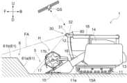
以下では、本実施形態における普通型のコンバイン(本発明に係る「農作業機」に相当)について説明する。図1及び図2に示すように、コンバインの機体1は、収穫部H、左右のクローラ11aを有する走行装置11、運転部12、脱穀装置13、穀粒タンク14、搬送部16、穀粒排出装置18、衛星測位モジュール80を備えている。 [Overall configuration of the combine]
In the following, a normal type combine harvester (corresponding to the "agricultural machine" of the present invention) in this embodiment will be described. As shown in Figures 1 and 2, a
走行装置11は、コンバインの機体1における下部に備えられている。また、走行装置11は、エンジン(図示せず)からの動力によって駆動する。そして、コンバインは、走行装置11によって自走可能である。The traveling
また、運転部12、脱穀装置13、穀粒タンク14は、走行装置11の上側に備えられている。運転部12には、コンバインの作業を監視するオペレータが搭乗可能である。尚、オペレータは、コンバインの機外からコンバインの作業を監視していても良い。The driving
穀粒排出装置18は、穀粒タンク14の上側に設けられている。また、衛星測位モジュール80は、運転部12の上面に取り付けられている。The
収穫部Hは、機体1における前部に備えられている。そして、搬送部16は、収穫部Hの後側に設けられている。また、収穫部Hは、刈取装置15及びリール17を含んでいる。The harvesting section H is provided at the front of the
刈取装置15は、圃場5(図3参照)の植立穀稈を刈り取る。また、リール17は、機体左右方向に沿うリール軸芯17b周りに回転駆動しながら収穫対象の植立穀稈を掻き込む。刈取装置15により刈り取られた刈取穀稈は、搬送部16へ送られる。The
この構成により、収穫部Hは、圃場5の穀物(本発明に係る「作物」に相当)を収穫する。そして、コンバインは、刈取装置15によって圃場5の植立穀稈を刈り取りながら走行装置11によって走行する刈取走行が可能である。With this configuration, the harvesting section H harvests grains (corresponding to the "crop" of the present invention) in the
収穫部Hにより収穫された刈取穀稈は、搬送部16によって機体後方へ搬送される。これにより、刈取穀稈は脱穀装置13へ搬送される。The harvested stalks harvested by the harvesting section H are transported to the rear of the machine by the
脱穀装置13において、刈取穀稈は脱穀処理される。脱穀処理により得られた穀粒は、穀粒タンク14に貯留される。穀粒タンク14に貯留された穀粒は、必要に応じて、穀粒排出装置18によって機外に排出される。The harvested stalks are threshed in the threshing
ここで、コンバインは、図3及び図4に示すように、圃場外縁部6の内側に位置する圃場5において、穀物を収穫するように構成されている。尚、圃場外縁部6は、圃場5を囲む状態で設けられている。圃場外縁部6には、例えば、畦畔61や給排水ポンプ62(図8参照)等が含まれている。As shown in Figures 3 and 4, the combine is configured to harvest grains in a
コンバインは、図3に示すように、第1作業走行を実行可能に構成されている。第1作業走行とは、圃場5の外周領域SAにおいて行われる作業走行である。尚、外周領域SAとは、図4に示すように、圃場5内の外周部に位置する領域である。The combine harvester is configured to be able to perform a first work run, as shown in FIG. 3. The first work run is a work run that is performed in the outer peripheral area SA of the
本実施形態において、第1作業走行での周回数は1回である。しかしながら、本発明はこれに限定されず、第1作業走行での周回数は、2回以上のいかなる回数であっても良い。In this embodiment, the number of laps in the first work run is one. However, the present invention is not limited to this, and the number of laps in the first work run may be any number of laps, such as two or more.
そして、コンバインは、第1作業走行を行った後、図4に示すように、第2作業走行を行うことにより、圃場5における作業走行を実行可能である。第2作業走行とは、第1作業走行の後に外周領域SAよりも内側の作業対象領域CAにおいて行われる作業走行である。The combine can then perform a work run in the
即ち、コンバインは、圃場5の外周領域SAにおいて行われる作業走行である第1作業走行と、第1作業走行の後に外周領域SAよりも内側の作業対象領域CAにおいて行われる作業走行である第2作業走行と、によって圃場5における作業走行を実行可能に構成されている。In other words, the combine is configured to be able to perform work travel in the
尚、本実施形態における「作業走行」は、具体的には、植立穀稈を刈り取りながら走行する刈取走行である。しかしながら、本発明はこれに限定されず、本発明に係る「作業走行」として、走行しながら、植立穀稈の刈り取り以外の作業が行われても良い。The "work travel" in this embodiment specifically refers to a reaping travel in which the vehicle travels while reaping planted culms. However, the present invention is not limited to this, and the "work travel" according to the present invention may involve work other than reaping planted culms while traveling.
本実施形態においては、図3に示す第1作業走行は手動走行により行われる。また、図4に示す第2作業走行は自動走行により行われる。しかしながら、本発明はこれに限定されず、第1作業走行は自動走行により行われても良い。また、第2作業走行は手動走行により行われても良い。In this embodiment, the first work travel shown in FIG. 3 is performed by manual travel. Also, the second work travel shown in FIG. 4 is performed by automatic travel. However, the present invention is not limited to this, and the first work travel may be performed by automatic travel. Also, the second work travel may be performed by manual travel.
〔制御部に関する構成〕
図5に示すように、コンバインは、制御部20を備えている。制御部20は、自車位置算出部21、領域算出部22、第1経路生成部23、自動走行制御部24を有している。自動走行制御部24は、コンバインの自動走行を制御する。また、自動走行制御部24は、経路選択部27及び走行制御部29(本発明に係る「パラメータ調節部」に相当)を含んでいる。 [Configuration of the control unit]
As shown in Fig. 5, the combine harvester includes a
図1に示すように、衛星測位モジュール80は、GPS(グローバル・ポジショニング・システム)で用いられる人工衛星GSからのGPS信号を受信する。そして、図5に示すように、衛星測位モジュール80は、受信したGPS信号に基づいて、コンバインの自車位置を示す測位データを自車位置算出部21へ送る。As shown in FIG. 1, the
尚、本発明はこれに限定されない。衛星測位モジュール80は、GPSを利用するものでなくても良い。例えば、衛星測位モジュール80は、GPS以外のGNSS(GLONASS、Galileo、みちびき、BeiDou等)を利用するものであっても良い。However, the present invention is not limited to this. The
自車位置算出部21は、衛星測位モジュール80により出力された測位データに基づいて、コンバインの位置座標を経時的に算出する。算出されたコンバインの経時的な位置座標は、領域算出部22及び自動走行制御部24へ送られる。The vehicle
領域算出部22は、自車位置算出部21から受け取ったコンバインの経時的な位置座標に基づいて、図4に示すように、外周領域SA及び作業対象領域CAを算出する。The
より具体的には、領域算出部22は、自車位置算出部21から受け取ったコンバインの経時的な位置座標に基づいて、圃場5における第1作業走行でのコンバインの走行軌跡を算出する。そして、領域算出部22は、算出されたコンバインの走行軌跡に基づいて、コンバインが第1作業走行を行った領域を外周領域SAとして算出する。また、領域算出部22は、算出された外周領域SAにより囲まれた領域を、作業対象領域CAとして算出する。More specifically, the
例えば、図3においては、圃場5における第1作業走行でのコンバインの走行経路が矢印で示されている。この走行経路に沿った刈取走行が完了すると、圃場5は、図4に示す状態となる。For example, in FIG. 3, the travel path of the combine harvester in the first work run in the
図4に示すように、領域算出部22は、コンバインが第1作業走行を行った領域を外周領域SAとして算出する。また、領域算出部22は、算出された外周領域SAにより囲まれた領域を、作業対象領域CAとして算出する。As shown in FIG. 4, the
そして、図5に示すように、領域算出部22による算出結果は、第1経路生成部23へ送られる。Then, as shown in FIG. 5, the calculation result by the
第1経路生成部23は、領域算出部22から受け取った算出結果に基づいて、図4に示すように、作業対象領域CAにおける刈取走行のための走行経路である刈取走行経路LIを生成する。尚、図4に示すように、本実施形態においては、刈取走行経路LIは、縦横方向に延びる複数のメッシュ線である。また、複数のメッシュ線は直線でなくても良く、湾曲していても良い。The first
図5に示すように、第1経路生成部23により生成された複数の刈取走行経路LIは、自動走行制御部24へ送られる。As shown in FIG. 5, the multiple harvesting driving routes LI generated by the first
自動走行制御部24における経路選択部27は、自車位置算出部21から受け取ったコンバインの位置座標と、第1経路生成部23から受け取った複数の刈取走行経路LIと、に基づいて、コンバインが次に走行するべき刈取走行経路LIを選択する。経路選択部27により選択された刈取走行経路LIを示す情報は、走行制御部29へ送られる。The
走行制御部29は、走行装置11を制御可能に構成されている。そして、走行制御部29は、自車位置算出部21から受け取ったコンバインの位置座標と、経路選択部27により選択された刈取走行経路LIを示す情報と、に基づいて、コンバインの自動走行を制御する。より具体的には、走行制御部29は、図4に示すように、刈取走行経路LIに沿った自動走行によって刈取走行が行われるように、コンバインの走行を制御する。The
この自動走行において、走行制御部29は、現在走行している刈取走行経路LIの次に、経路選択部27により選択された刈取走行経路LIに沿った刈取走行が行われるように、コンバインの走行を制御する。In this automatic driving, the driving
図1及び図5に示すように、コンバインは、刈取シリンダ15Aを備えている。また、図5に示すように、制御部20は、昇降制御部40(本発明に係る「パラメータ調節部」に相当)を有している。As shown in Figures 1 and 5, the combine harvester is equipped with a
昇降制御部40は、刈取シリンダ15Aを制御可能に構成されている。昇降制御部40が刈取シリンダ15Aを伸び方向に制御すると、搬送部16及び収穫部Hは、一体的に、収穫部Hが上昇する方向に揺動する。これにより、収穫部Hは上昇する。The lifting
また、昇降制御部40が刈取シリンダ15Aを縮み方向に制御すると、搬送部16及び収穫部Hは、一体的に、収穫部Hが下降する方向に揺動する。これにより、収穫部Hは下降する。When the
この構成により、昇降制御部40は、収穫部Hの昇降を制御可能である。また、収穫部Hは昇降可能である。With this configuration, the lifting
即ち、コンバインは、昇降可能に構成されると共に圃場5の穀物を収穫する収穫部Hを備えている。That is, the combine is configured to be able to rise and fall and is equipped with a harvesting section H that harvests grains from the
以上で説明した構成により、機体1における収穫部Hの地上からの高さは、刈取シリンダ15Aの伸縮方向での長さに応じて決まる。即ち、刈取シリンダ15Aの伸縮方向での長さは、機体1の状態を決定する制御パラメータである。より具体的には、刈取シリンダ15Aの伸縮方向での長さは、収穫部Hの高さを決定する制御パラメータである。With the configuration described above, the height of the harvesting section H of the
そして、昇降制御部40は、機体1の状態を決定する制御パラメータを調節する。より具体的には、昇降制御部40は、刈取シリンダ15Aの伸縮方向での長さを調節する。尚、刈取シリンダ15Aの伸縮方向での長さは、本発明に係る「収穫高さパラメータ」に相当する。The
尚、制御部20、及び、制御部20に含まれる自車位置算出部21等の各要素は、マイクロコンピュータ等の物理的な装置であっても良いし、ソフトウェアにおける機能部であっても良い。The
〔検出部の構成〕
図1、図2、図5に示すように、本実施形態のコンバインは、検出部30を備えている。検出部30は、圃場外縁部6のうち、機体1の進行方向前方に位置する部分を検出対象として、コンバインの圃場走行中に、圃場外縁部6の状態を検出する。 [Configuration of the detection unit]
1, 2, and 5, the combine harvester of this embodiment is equipped with a
即ち、コンバインは、圃場5を囲む状態で設けられた圃場外縁部6のうち、機体1の進行方向前方に位置する部分を検出対象として、圃場走行中に圃場外縁部6の状態を検出する検出部30を備えている。That is, the combine harvester is equipped with a
詳述すると、検出部30は、検出装置31及び撮像装置32を有している。本実施形態における検出装置31は、ToF(Time of flight)測定方式の測定装置である二次元スキャンLiDARである。尚、本発明はこれに限定されず、検出装置31は、三次元スキャンLiDARであっても良い。また、検出装置31の測定方式は、ToF測定方式に限定されず、ステレオマッチング測定方式等であっても良い。More specifically, the
尚、本発明に係る「圃場走行」は、圃場5において走行することを意味する。例えば、圃場5における最外周部分を走行することは、本発明に係る「圃場走行」の具体例である。また、圃場5における最外周部分よりも内側を走行することも、本発明に係る「圃場走行」の具体例である。In addition, "field travel" according to the present invention means travel in the
図5に示すように、自車位置算出部21により算出されたコンバインの位置座標は、検出部30へ送られる。そして、検出装置31は、ToF測定方式の測定結果と、自車位置算出部21から受け取ったコンバインの位置座標と、に基づいて、前方領域FA(図1参照)に存在する物体の位置及び高さを示す点群データを出力する。この構成により、検出装置31は、圃場走行中に、機体1の進行方向前方に位置する領域である前方領域FAに存在する物体の位置及び高さを検出する。As shown in FIG. 5, the position coordinates of the combine calculated by the vehicle
また、撮像装置32は、圃場走行中に前方領域FAを撮像する。本実施形態における撮像装置32は、色情報を含む撮影画像を取得するカメラである。The
即ち、検出部30は、圃場走行中に、機体1の進行方向前方に位置する領域である前方領域FAに存在する物体の位置及び高さを検出する検出装置31と、圃場走行中に前方領域FAを撮像する撮像装置32と、を有している。That is, the
尚、本実施形態において、検出装置31による検出範囲、及び、撮像装置32による撮像範囲は、何れも、図1及び図2に示す前方領域FAに一致している。しかしながら、本発明はこれに限定されず、検出装置31による検出範囲と、撮像装置32による撮像範囲と、は互いに一致していなくても良い。In this embodiment, the detection range of the
そして、検出部30は、検出装置31による検出結果と、撮像装置32による撮像結果と、に基づいて圃場外縁部6の状態を検出する。Then, the
詳述すると、本実施形態における検出部30は、検出装置31により出力された点群データに、撮像装置32により取得された撮像画像を処理して得られる色情報を付与する。そして、検出部30は、色情報の付与された点群データに基づいて、圃場5と圃場外縁部6との境界を判定する。そして、検出部30は、点群データのうち、圃場外縁部6に対応するデータに基づいて、圃場外縁部6の立体形状を検出する。In more detail, the
尚、撮像装置32により取得された撮像画像に対して、機械学習されたニューラルネットワークを利用した画像認識を行うことにより、圃場5と圃場外縁部6との境界が判定されても良い。The boundary between the
また、検出部30は、圃場外縁部6における畦畔61以外の物体(例えば、給排水ポンプ62や樹木等)の存否を検出するように構成されていても良い。圃場外縁部6の立体形状、及び、圃場外縁部6における畦畔61以外の物体の存否は、何れも、本発明に係る「圃場外縁部の状態」の具体例である。The
図5に示すように、検出部30による検出結果は、昇降制御部40へ送られる。昇降制御部40は、検出部30による検出結果に基づいて、収穫部Hが圃場外縁部6に干渉しないように、収穫部Hの昇降を制御する。このとき、昇降制御部40は、刈取シリンダ15Aの伸縮方向での長さを調節することにより、収穫部Hの昇降を制御する。As shown in FIG. 5, the detection result by the
このように、昇降制御部40は、検出部30による検出結果に基づいて、収穫部Hの高さを決定する制御パラメータである刈取シリンダ15Aの伸縮方向での長さを調節する。言い換えれば、コンバインは、検出部30による検出結果に基づいて、機体1の状態を決定する制御パラメータを調節する昇降制御部40を備えている。In this way, the lifting
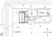
図6には、検出部30による検出結果に基づいて収穫部Hの高さが制御される場合の例が示されている。図6に示すように、畦畔61は、側面部61a及び上面部61bを有している。側面部61aは、外側ほど(圃場5から離れるほど)高くなるように傾斜している。また、上面部61bは水平である。Figure 6 shows an example in which the height of the harvesting section H is controlled based on the detection results from the
この例では、コンバインが圃場外縁部6の近傍で方向転換(本発明に係る「第1方向転換」に相当)を行う。そして、方向転換の途中で、一時的に、収穫部Hが平面視で圃場外縁部6に重複する状態となる。このとき、昇降制御部40は、検出部30による検出結果に基づいて、収穫部Hと圃場外縁部6との間の離間距離D1が所定値よりも広い状態が維持されるように、刈取シリンダ15Aの伸縮方向での長さを調節する。尚、この所定値は、任意に設定可能である。 In this example, the combine harvester changes direction(corresponding to the "first direction change" according to the present invention) near the field
尚、検出部30による検出結果に基づいた昇降制御部40による刈取シリンダ15Aの伸縮方向での長さの調節は、コンバインが手動走行しているときに実行されても良いし、コンバインが自動走行しているときに実行されても良い。The adjustment of the length of the
また、本実施形態における検出部30は、圃場外縁部6だけでなく、圃場5の状態も検出可能に構成されている。より具体的には、検出部30は、圃場5における植立穀稈の高さや倒伏度合いを検出可能である。In addition, the
以上で説明した構成によれば、コンバインが圃場5において作業走行をしているときに、検出部30による検知がリアルタイムに行われると共に、検出部30によるリアルタイムでの検知結果に基づいて、機体1の状態を決定する制御パラメータが調節される。According to the configuration described above, when the combine harvester is working in the
そして、後述の未確認領域UAや外縁部マップに基づいて制御パラメータが調節される構成において、検出部30によるリアルタイムでの検知結果にも基づいて制御パラメータが調節されることにより、高精度な制御パラメータの調節が実現できる。In a configuration in which the control parameters are adjusted based on the unconfirmed area UA and outer edge map described below, the control parameters are also adjusted based on the real-time detection results by the
また、検出部30によるリアルタイムでの検知結果に基づいて制御パラメータが調節される構成であれば、未確認領域UAや外縁部マップに依存することなく、制御パラメータを適切に調節することも可能である。即ち、検出部30によるリアルタイムでの検知結果に基づいて制御パラメータが調節される構成であれば、未確認領域UAを決定するための構成や、外縁部マップを生成するための構成を省くことも可能である。Furthermore, if the control parameters are adjusted based on the real-time detection results by the
〔未確認領域の決定に関する構成〕
図5に示すように、制御部20は、未確認領域決定部26を備えている。検出部30による検出結果は、未確認領域決定部26へ送られる。未確認領域決定部26は、検出部30による検出結果に基づいて、圃場外縁部6のうち、検出部30による状態の検出が不完全な領域である未確認領域UA(図7参照)を決定する。 [Structure regarding the determination of unconfirmed areas]
As shown in Fig. 5, the
即ち、コンバインは、検出部30による検出結果に基づいて、圃場外縁部6のうち、検出部30による状態の検出が不完全な領域である未確認領域UAを決定する未確認領域決定部26を備えている。That is, the combine harvester is equipped with an unconfirmed
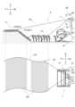
図7では、未確認領域決定部26により未確認領域UAが決定される場合の例が示されている。この例では、圃場5において、穀物が畦畔61のすぐ近くまで植えられている。また、図7の上部に示すように、検出部30による検出は植立穀稈の頂部によって阻まれるため、前方領域FAのうち、図7に示す下限ラインLLよりも下側は、検出部30による検出の死角となる。Figure 7 shows an example of a case where an unconfirmed area UA is determined by the unconfirmed
このとき、未確認領域決定部26は、検出部30による検出結果に基づいて、未確認領域UA及び検出済領域DAを決定する。尚、検出済領域DAは、圃場5及び圃場外縁部6のうち、検出部30による状態の検出が行われた領域である。より具体的には、検出済領域DAは、検出部30による状態の検出が十分に行われ、存在する物体の種類や、その物体の位置及び高さが検出された領域である。At this time, the unconfirmed
図7に示す例では、圃場外縁部6のうち、下限ラインLLよりも下側に位置する部分は、検出部30による状態の検出が不完全である。より具体的には、側面部61aにおける下部は、検出部30による状態の検出が不完全である。そのため、図7の下部に示すように、側面部61aにおける下部に対応する領域は、未確認領域決定部26によって未確認領域UAとして決定される。In the example shown in FIG. 7, the portion of the
尚、本実施形態においては、対応する点群データが存在しない領域が、未確認領域UAとして決定される。また、対応する点群データが存在する領域が、検出済領域DAとして決定される。In this embodiment, an area where no corresponding point cloud data exists is determined as an unconfirmed area UA. An area where corresponding point cloud data exists is determined as a detected area DA.
また、前方領域FAのうち、未確認領域UAに対してコンバイン側に位置する領域の状態は、検出部30によって十分に検出されている。より具体的には、検出部30によってこの領域における植立穀稈の位置及び高さが検出されている。そのため、この領域は、未確認領域決定部26によって検出済領域DAとして決定される。The condition of the area of the forward area FA that is located on the combine side of the unconfirmed area UA has been sufficiently detected by the
また、前方領域FAのうち、未確認領域UAに対してコンバインとは反対側に位置する領域の状態は、検出部30によって十分に検出されている。より具体的には、検出部30によってこの領域における畦畔61の位置及び立体形状が十分に検出されている。そのため、この領域は、未確認領域決定部26によって検出済領域DAとして決定される。The state of the area of the forward area FA that is located on the opposite side of the combine from the unconfirmed area UA has been sufficiently detected by the
尚、未確認領域決定部26により決定される未確認領域UA及び検出済領域DAは、二次元の領域(平面において規定される領域)であっても良いし、三次元の領域(空間において規定される領域)であっても良い。The unconfirmed area UA and the detected area DA determined by the unconfirmed
また、本実施形態において、未確認領域決定部26は、検出部30による現時点での検出結果のみに基づいて、未確認領域UA及び検出済領域DAを決定する。しかしながら、本発明はこれに限定されず、未確認領域決定部26は、検出部30による経時的な検出結果に基づいて、未確認領域UA及び検出済領域DAを決定しても良い。In addition, in this embodiment, the unconfirmed
例えば、未確認領域決定部26は、検出部30による経時的な検出結果に基づいて、検出マップを生成しても良い。この場合、この検出マップは、未確認領域UA及び検出済領域DAの分布を示すマップである。For example, the unconfirmed
検出マップが生成される構成では、コンバインが圃場5における刈取走行を開始する前は、検出マップの全体が未確認領域UAである。そして、コンバインが圃場5における刈取走行を進めていくことに伴い、検出部30によって状態の検出された領域が拡大していく。そのため、コンバインが圃場5における刈取走行を進めていくことに伴い、検出マップにおける検出済領域DAが拡大していくと共に、未確認領域UAが狭まっていくことになる。In a configuration in which a detection map is generated, before the combine harvester starts its harvesting journey in the
〔未確認領域に基づく制御〕
図5に示すように、未確認領域決定部26により決定された未確認領域UA及び検出済領域DAを示す情報は、走行制御部29へ送られる。走行制御部29は、この情報に基づいて、走行装置11を制御する。 [Control based on unidentified areas]
5, information indicating the unconfirmed area UA and the detected area DA determined by the unconfirmed
詳述すると、走行制御部29は、自車位置算出部21から受け取ったコンバインの位置座標と、未確認領域UA及び検出済領域DAを示す情報と、に基づいて、所定条件が満たされているか否かを判定する。本実施形態において、この所定条件は、「コンバインが未確認領域UAに近づく方向に走行しており、且つ、コンバインの現在位置から未確認領域UAまでの距離が所定距離以下である」ことである。この所定条件が満たされていると判定された場合、走行制御部29は、車速が減少するように、走行装置11におけるクローラ11aの回転速度を調節する。このとき、走行制御部29は、クローラ11aの回転速度を減少させる。尚、この所定条件は、適宜変更しても良い。In more detail, the
尚、本実施形態のコンバインにおいて、車速は、クローラ11aの回転速度に応じて決まる。即ち、クローラ11aの回転速度は、機体1の状態を決定する制御パラメータである。より具体的には、クローラ11aの回転速度は、車速を決定する制御パラメータである。そして、クローラ11aの回転速度は、本発明に係る「車速パラメータ」に相当する。In the combine harvester of this embodiment, the vehicle speed is determined according to the rotational speed of the
このように、走行制御部29は、未確認領域UAに基づいてクローラ11aの回転速度を調節する。In this way, the driving
また、以上で説明した通り、未確認領域決定部26により決定される未確認領域UAは、検出部30による検出結果に基づいている。即ち、走行制御部29は、検出部30による検出結果に基づいて、車速を決定する制御パラメータであるクローラ11aの回転速度を調節する。言い換えれば、コンバインは、検出部30による検出結果に基づいて、機体1の状態を決定する制御パラメータを調節する走行制御部29を備えている。As described above, the unconfirmed area UA determined by the unconfirmed
尚、未確認領域UA、あるいは、検出部30による検出結果に基づいた走行制御部29によるクローラ11aの回転速度の調節は、コンバインが手動走行しているときに実行されても良いし、コンバインが自動走行しているときに実行されても良い。The adjustment of the rotational speed of the
〔外縁部マップに関する構成〕
図5に示すように、制御部20は、マップ生成部25を有している。検出部30による検出結果は、マップ生成部25へ送られる。 [Configuration regarding outer edge map]
5, the
マップ生成部25は、検出部30による検出結果に基づいて、外縁部マップを生成する。外縁部マップとは、圃場外縁部6の状態の分布を示すマップである。本実施形態における外縁部マップは、圃場外縁部6の立体形状の分布を示すものである。The
即ち、コンバインは、検出部30による検出結果に基づいて圃場外縁部6の状態の分布を示す外縁部マップを生成するマップ生成部25を備えている。That is, the combine harvester is equipped with a
図8には、マップ生成部25により生成される外縁部マップの一例が示されている。図8に示す外縁部マップには、畦畔61の側面部61aの位置及び立体形状と、畦畔61の上面部61bの位置及び立体形状と、給排水ポンプ62の位置及び立体形状と、が含まれている。Figure 8 shows an example of an outer edge map generated by the
尚、図8に示す外縁部マップは、圃場外縁部6の全周に対応している。即ち、この外縁部マップは、圃場外縁部6の全周に亘る状態の分布を示している。しかしながら、本発明はこれに限定されない。The edge map shown in FIG. 8 corresponds to the entire circumference of the
例えば、圃場外縁部6の一部のみの状態が検出部30によって検出済みであるときに、その部分のみの状態の分布を示すマップが、外縁部マップとして生成されても良い。また、この場合、コンバインが圃場5を走行し、検出部30によって状態の検出された領域が拡大していくに伴って、外縁部マップが更新されていくように構成されていても良い。この場合、コンバインが圃場5における刈取走行を進めていくことに伴い、外縁部マップにより示される領域が拡大していくこととなる。For example, when the condition of only a portion of the field
また、図5に示すように、自動走行制御部24は、第2経路生成部28(本発明に係る「経路生成部」に相当)を有している。マップ生成部25により生成された外縁部マップは、第2経路生成部28へ送られる。そして、第2経路生成部28は、第2作業走行のための目標走行経路TL(図6及び図9参照)を生成する。As shown in FIG. 5, the automatic
以下では、目標走行経路TLについて詳述する。The target driving route TL is described in detail below.
図6では、コンバインが圃場外縁部6の近傍で方向転換をする例が示されている。この例では、マップ生成部25により、外縁部マップが既に生成されている。また、この例では、コンバインは、自動走行によって上述の第2作業走行を行っている。Figure 6 shows an example in which the combine harvester changes direction near the
図6に示す例では、コンバインは、まず、作業対象領域CAにおいて刈取走行を行いながら直進する。そして、収穫部Hが作業対象領域CAから外周領域SAに進入すると、コンバインは、αターンによって方向転換を行う。In the example shown in FIG. 6, the combine first moves straight ahead while performing harvesting travel in the work area CA. Then, when the harvesting section H enters the outer peripheral area SA from the work area CA, the combine changes direction by making an α turn.
より具体的には、収穫部Hが作業対象領域CAから外周領域SAに進入すると、走行制御部29の制御により、コンバインは、減速しながら機体左側へ旋回する。そして、コンバインは、収穫部Hが平面視で圃場外縁部6に重複する状態で、一旦停止する。More specifically, when the harvesting section H enters the outer peripheral area SA from the work target area CA, the combine turns to the left side of the machine body while decelerating under the control of the
その後、コンバインは後進及び前進を行いながら、機体1の向きを変更する。これにより、コンバインの方向転換が完了する。The combine then moves backward and forward while changing the direction of the
ここで、収穫部Hが作業対象領域CAから外周領域SAに進入する前に、第2経路生成部28は、経路選択部27により選択された刈取走行経路LIを示す情報を受け取る。そして、第2経路生成部28は、この情報と、マップ生成部25から受け取った外縁部マップと、に基づいて、方向転換の際に目標となるコンバインの走行経路である目標走行経路TLを生成する。このとき、第2経路生成部28は、圃場外縁部6の状態の分布に応じて、コンバインが効率的に方向転換できるように、且つ、方向転換の際に収穫部Hが圃場外縁部6に干渉しないように、目標走行経路TLを生成する。尚、図6では、刈取走行経路LIの図示を省略している。Here, before the harvesting unit H enters the outer peripheral area SA from the work target area CA, the second
即ち、コンバインは、外縁部マップに基づいて第2作業走行のための目標走行経路TLを生成する第2経路生成部28を備えている。That is, the combine is equipped with a second
そして、走行制御部29は、生成された目標走行経路TLに沿ってコンバインが方向転換を行うように、コンバインの走行を制御する。このとき、走行制御部29は、目標走行経路TLに基づいて、走行装置11における左右のクローラ11aの速度差を調節する。Then, the
尚、本実施形態のコンバインにおいて、機体1の旋回状態は、左右のクローラ11aの速度差に応じて決まる。即ち、左右のクローラ11aの速度差は、機体1の状態を決定する制御パラメータである。より具体的には、左右のクローラ11aの速度差は、旋回状態を決定する制御パラメータである。そして、左右のクローラ11aの速度差は、本発明に係る「旋回パラメータ」に相当する。In the combine harvester of this embodiment, the turning state of the
また、以上で説明した通り、第2経路生成部28により生成される目標走行経路TLは、外縁部マップに基づいている。マップ生成部25により生成される外縁部マップは、検出部30による検出結果に基づいている。即ち、走行制御部29は、検出部30による検出結果に基づいて、旋回状態を決定する制御パラメータである左右のクローラ11aの速度差を調節する。As described above, the target driving path TL generated by the second
尚、検出部30による検出結果に基づいた走行制御部29による左右のクローラ11aの速度差の調節は、コンバインが手動走行しているときに実行されても良いし、コンバインが自動走行しているときに実行されても良い。The speed difference between the left and
また、コンバインが方向転換を行う際、圃場外縁部6のうち、機体1の進行方向前方に位置する部分の地上高さが所定高さよりも高い場合、第2経路生成部28は、図6に示すようなαターンの目標走行経路TLではなく、図9に示すような目標走行経路TLを生成する。尚、この所定高さは、任意に設定可能である。また、図9では、刈取走行経路LIの図示を省略している。そして、走行制御部29は、生成された目標走行経路TLに沿ってコンバインが方向転換(本発明に係る「第2方向転換」に相当)を行うように、コンバインの走行を制御する。 Furthermore, when the combine harvester changes direction, if the ground height of the portion of the field
図9に示す例では、コンバインは、まず、作業対象領域CAにおいて刈取走行を行いながら直進する。そして、収穫部Hが作業対象領域CAから外周領域SAに進入した後、コンバインは、収穫部Hが平面視で圃場外縁部6に重複しない状態で、一旦停止する。In the example shown in FIG. 9, the combine first moves straight ahead while performing harvesting driving in the work area CA. Then, after the harvesting section H enters the outer peripheral area SA from the work area CA, the combine stops once the harvesting section H does not overlap the
その後、コンバインは後進及び前進を繰り返しながら、機体1の向きを変更する。これにより、コンバインの方向転換が完了する。The combine then changes the direction of the
以上で説明した構成であれば、圃場外縁部6のうち、機体1の進行方向前方に位置する部分の状態に応じて、制御パラメータが調節される。これにより、圃場外縁部6のうち、機体1の進行方向前方に位置する部分の状態に応じて、機体1が制御されることとなる。従って、以上で説明した構成であれば、圃場外縁部6のうち、機体1の進行方向前方に位置する部分の状態に応じて機体1を制御可能なコンバインを実現できる。With the configuration described above, the control parameters are adjusted according to the state of the portion of the
〔その他の実施形態〕
(1)走行装置11は、ホイール式であっても良いし、セミクローラ式であっても良い。例えば、走行装置11がホイール式である場合、ホイールの回転速度は、本発明に係る「車速パラメータ」に相当する。また、旋回時のホイールの切れ角は、本発明に係る「旋回パラメータ」に相当する。 Other embodiments
(1) The traveling
(2)上記実施形態においては、第1経路生成部23により生成される刈取走行経路LIは、縦横方向に延びる複数のメッシュ線である。しかしながら、本発明はこれに限定されず、第1経路生成部23により生成される刈取走行経路LIは、縦横方向に延びる複数のメッシュ線でなくても良い。例えば、第1経路生成部23により生成される刈取走行経路LIは、渦巻き状の走行経路であっても良い。また、刈取走行経路LIは、別の刈取走行経路LIと直交していなくても良い。また、第1経路生成部23により生成される刈取走行経路LIは、互いに平行な複数の平行線であっても良い。(2) In the above embodiment, the mowing travel path LI generated by the first
(3)自車位置算出部21、領域算出部22、第1経路生成部23、自動走行制御部24、マップ生成部25、未確認領域決定部26、経路選択部27、第2経路生成部28、走行制御部29、昇降制御部40のうち、一部または全てがコンバインの外部に備えられていても良いのであって、例えば、コンバインの外部に設けられた管理施設や管理サーバに備えられていても良い。(3) Some or all of the vehicle
(4)コンバインは、自動走行ができないように構成されていても良い。(4) The combine may be configured so that it cannot travel automatically.
(5)上記実施形態においては、昇降制御部40は、収穫部Hと圃場外縁部6との間の離間距離D1が所定値よりも広い状態が維持されるように、収穫部Hの昇降を制御する。しかしながら、本発明はこれに限定されず、このような所定値が設定されていなくても良い。(5) In the above embodiment, the lifting
(6)外縁部マップは、畦畔61の側面部61aにおける最も低い部分の位置及び高さと、畦畔61の側面部61aにおける最も高い部分の位置及び高さと、を示すものであっても良い。(6) The outer edge map may show the position and height of the lowest part of the
(7)上記実施形態においては、領域算出部22が、コンバインが第1作業走行を行った領域を外周領域SAとして算出する。しかしながら、本発明はこれに限定されない。外周領域SAは、コンバインが第1作業走行を行う前に決定されていても良い。(7) In the above embodiment, the
(8)第1経路生成部23は、外縁部マップに基づいて刈取走行経路LIを生成しても良い。この場合、第1経路生成部23は本発明に係る「経路生成部」に相当し、刈取走行経路LIは本発明に係る「目標走行経路」に相当する。(8) The first
(9)昇降制御部40は、未確認領域UAに基づいて刈取シリンダ15Aの伸縮方向での長さを調節しても良い。例えば、昇降制御部40は、収穫部Hが平面視で未確認領域UAに重複する状態となる際、刈取シリンダ15Aを設計上の最大長さまで伸ばすように構成されていても良い。これにより、収穫部Hは、設計上の最上昇位置まで上昇することとなる。(9) The
(10)上記実施形態において、未確認領域決定部26は、圃場5及び圃場外縁部6のうち、検出部30による状態の検出が行われた領域を検出済領域DAとして決定する。しかしながら、本発明はこれに限定されない。未確認領域決定部26は、圃場外縁部6についてのみ、検出済領域DAを決定するように構成されていても良い。(10) In the above embodiment, the unconfirmed
(11)上記実施形態において、走行制御部29は、未確認領域UAに基づいてクローラ11aの回転速度を調節する。しかしながら、本発明はこれに限定されない。走行制御部29は、未確認領域UAに基づくことなく、クローラ11aの回転速度を調節するように構成されていても良い。(11) In the above embodiment, the
例えば、走行制御部29は、検出部30による検出結果を受け取って、その検出結果に基づいて、クローラ11aの回転速度を調節するように構成されていても良い。この場合、例えば、走行制御部29は、コンバインが圃場外縁部6に近づく方向に走行しており、且つ、コンバインの現在位置から圃場外縁部6までの距離が所定距離以下である場合に、クローラ11aの回転速度を減少させても良い。For example, the
(12)上記実施形態において、走行制御部29は、目標走行経路TLに基づいて左右のクローラ11aの速度差を調節する。しかしながら、本発明はこれに限定されない。走行制御部29は、目標走行経路TLに基づくことなく、左右のクローラ11aの速度差を調節するように構成されていても良い。(12) In the above embodiment, the
例えば、走行制御部29は、検出部30による検出結果を受け取って、その検出結果に基づいて、左右のクローラ11aの速度差を調節するように構成されていても良い。この場合、例えば、走行制御部29は、コンバインが圃場外縁部6に近づく方向に走行しており、且つ、コンバインの現在位置から圃場外縁部6までの距離が所定距離以下である場合に、コンバインが圃場外縁部6に近づかない方向へコンバインの進行方向を変化させるように、左右のクローラ11aの速度差を調節しても良い。For example, the
(13)上記実施形態においては、本発明を適用したコンバインについて説明した。しかしながら、本発明はコンバインに限定されない。例えば、本発明が田植機(本発明に係る「農作業機」に相当)に適用されても良い。即ち、上記実施形態についての説明のうち、田植機にも適用可能な部分は、田植機にも同様に当てはまる。(13) In the above embodiment, a combine harvester to which the present invention is applied has been described. However, the present invention is not limited to combine harvesters. For example, the present invention may be applied to a rice transplanter (corresponding to the "agricultural machine" of the present invention). In other words, the parts of the description of the above embodiment that are applicable to a rice transplanter also apply to a rice transplanter.
例えば、田植機の後部に、苗載せ台を有する苗植付装置が備えられており、且つ、この田植機が、苗植付装置を昇降させる油圧式の昇降シリンダと、検出部30と、昇降制御部40と、を備えていても良い。そして、昇降制御部40が、この昇降シリンダを制御可能に構成されていても良い。For example, the rice transplanter may be provided with a seedling planting device having a seedling platform at the rear, and the rice transplanter may be provided with a hydraulic lifting cylinder for raising and lowering the seedling planting device, a
この構成において、昇降制御部40は、苗植付装置の昇降を制御可能である。また、昇降シリンダの伸縮方向での長さ、及び、苗植付装置の昇降高さは、本発明に係る「制御パラメータ」に相当する。In this configuration, the lifting
この構成において、昇降制御部40は、検出部30による検出結果に基づいて、苗植付装置が圃場外縁部6に干渉しないように、苗植付装置の昇降を制御するように構成されていても良い。In this configuration, the lifting
例えば、昇降制御部40は、検出部30による検出結果に基づいて、苗植付装置が畦畔61に干渉しないように、苗植付装置の昇降を制御するように構成されていても良い。また、圃場外縁部6に障害物が存在する場合、昇降制御部40は、検出部30による検出結果に基づいて、苗植付装置がその障害物に干渉しないように、苗植付装置の昇降を制御するように構成されていても良い。For example, the lifting
また、この田植機が、左右の前車輪及び左右の後車輪を備えると共に、走行制御部29を備えていても良い。この場合、走行制御部29は、検出部30による検出結果に基づいて、車速を決定する制御パラメータである左右の前車輪及び左右の後車輪の回転速度を調節するように構成されていても良い。The rice transplanter may also be equipped with left and right front wheels and left and right rear wheels, as well as a driving
さらに、この田植機における前車輪または後車輪が操向可能な操向輪として構成されている場合、走行制御部29は、検出部30による検出結果に基づいて、旋回状態を決定する制御パラメータである操向輪の切れ角を調節するように構成されていても良い。Furthermore, if the front or rear wheels of this rice transplanter are configured as steerable wheels, the
また、この田植機において、検出部30による検出は、前進走行中に行われても良いし、後進走行中に行われても良い。尚、後進走行中において、田植機の機体の後方は、本発明に係る「機体の進行方向前方」に相当する。また、この田植機において、昇降制御部40及び走行制御部29による制御パラメータの調節は、前進走行中に行われても良いし、後進走行中に行われても良い。In addition, in this rice transplanter, detection by the
(14)上記実施形態においては、本発明を適用したコンバインについて説明した。しかしながら、本発明はコンバインに限定されない。例えば、本発明がトラクタ(本発明に係る「農作業機」に相当)あるいはトラクタのインプルメント(本発明に係る「農作業機」に相当)に適用されても良い。即ち、上記実施形態についての説明のうち、トラクタやインプルメントにも適用可能な部分は、トラクタやインプルメントにも同様に当てはまる。(14) In the above embodiment, a combine harvester to which the present invention is applied has been described. However, the present invention is not limited to combine harvesters. For example, the present invention may be applied to a tractor (corresponding to the "farm work machine" of the present invention) or a tractor implement (corresponding to the "farm work machine" of the present invention). In other words, the parts of the description of the above embodiment that are applicable to a tractor or implement also apply to a tractor or implement.
例えば、トラクタの後部に、インプルメントである畦塗り機が取り付けられており、且つ、このトラクタあるいは畦塗り機が、畦塗り機の左右位置や傾き等を変化させるアクチュエータと、検出部30と、畦塗り制御部(本発明に係る「パラメータ調節部」に相当)と、を備えていても良い。そして、畦塗り制御部が、このアクチュエータを制御可能に構成されていても良い。For example, a ridge coating implement may be attached to the rear of a tractor, and the tractor or ridge coating may include an actuator that changes the left/right position and inclination of the ridge coating implement, a
この構成において、畦塗り制御部は、畦塗り機の左右位置や傾き等を制御可能である。また、畦塗り機の左右位置や傾き等は、本発明に係る「制御パラメータ」に相当する。In this configuration, the ridge coating control unit can control the left-right position and inclination of the ridge coating machine. Furthermore, the left-right position and inclination of the ridge coating machine correspond to the "control parameters" according to the present invention.
この構成において、畦塗り制御部は、検出部30による検出結果に基づいて、好適な畦畔61が形成されるように、畦塗り機の左右位置や傾き等を制御するように構成されていても良い。この場合、畦塗り制御部は、検出部30による検出結果に基づいて、畦塗り機の左右位置や傾き等を調節することとなる。In this configuration, the ridge painting control unit may be configured to control the left-right position and inclination of the ridge painting machine based on the detection results by the
尚、上述の実施形態(別実施形態を含む、以下同じ)で開示される構成は、矛盾が生じない限り、他の実施形態で開示される構成と組み合わせて適用することが可能である。また、本明細書において開示された実施形態は例示であって、本発明の実施形態はこれに限定されず、本発明の目的を逸脱しない範囲内で適宜改変することが可能である。The configurations disclosed in the above-mentioned embodiments (including other embodiments, the same applies below) can be applied in combination with configurations disclosed in other embodiments, so long as no contradiction occurs. Furthermore, the embodiments disclosed in this specification are merely examples, and the present invention is not limited to these embodiments, and can be modified as appropriate within the scope of the purpose of the present invention.
本発明は、普通型のコンバインだけではなく、自脱型のコンバイン、トラクタ、田植機、トウモロコシ収穫機、ジャガイモ収穫機、ニンジン収穫機等、種々の農作業機に利用可能である。The present invention can be used not only in standard combine harvesters, but also in a variety of agricultural machines, including head-feeding combine harvesters, tractors, rice transplanters, corn harvesters, potato harvesters, and carrot harvesters.
1 機体
5 圃場
6 圃場外縁部
24 自動走行制御部
25 マップ生成部
26 未確認領域決定部
28 第2経路生成部(経路生成部)
29 走行制御部(パラメータ調節部)
30 検出部
31 検出装置
32 撮像装置
40 昇降制御部(パラメータ調節部)
CA 作業対象領域
FA 前方領域
H 収穫部
SA 外周領域
TL 目標走行経路
UA 未確認領域 1
24 Automatic driving control unit
25
29 Driving control unit (parameter adjustment unit)
30
CA Working area FA Forward area H Harvesting area SA Outer periphery area TL Target travel route UA Unconfirmed area
Claims (8)
Translated fromJapanese前記検出部による検出結果に基づいて、前記機体の状態を決定する制御パラメータを調節するパラメータ調節部と、
昇降可能に構成されると共に前記圃場の作物を収穫する収穫部と、
前記機体の自動走行を制御する自動走行制御部と、を備え、
前記自動走行制御部による制御によって、前記収穫部が平面視で前記圃場外縁部に一時的に重複する方向転換である第1方向転換、及び、前記収穫部が平面視で前記圃場外縁部に重複しない方向転換である第2方向転換を行うことが可能であり、
前記圃場外縁部のうち前記機体の進行方向前方に位置する部分の高さに応じて、前記第1方向転換または前記第2方向転換を行う農作業機。 a detection unit that detects the state of a field edge portion surrounding the field while traveling in the field, the detection unit detecting a portion of the field edge portion that is located forward in the traveling direction of the machine body as a detection target;
a parameter adjustment unit that adjusts a control parameter that determines a state of the aircraft based on a detection result by the detection unit;
A harvesting unit configured to be liftable and lowerable and harvesting crops in the field;
An automatic driving control unit that controls automatic driving of the aircraft,
By controlling the automatic driving control unit, it is possible to perform a first direction change, which is a direction change in which the harvesting unit temporarily overlaps the outer edge of the field in a planar view, and a second direction change, which is a direction change in which the harvesting unit does not overlap the outer edge of the field in a planar view,
An agricultural work machinethat performs the first direction change or the second direction change depending on the height of a portion of the outer edge of the field that is located forward in the traveling direction of the machine body .
前記検出部による検出結果に基づいて、前記機体の状態を決定する制御パラメータを調節するパラメータ調節部と、
前記検出部による検出結果に基づいて、前記圃場外縁部のうち、前記検出部による状態の検出が不完全な領域である未確認領域を決定する未確認領域決定部と、を備え、
前記パラメータ調節部は、前記未確認領域に基づいて前記制御パラメータを調節する農作業機。a detection unit that detects the state of a field edge portion surrounding the field while traveling in the field, the detection unit detecting a portion of the field edge portion that is located forward in the traveling direction of the machine body as a detection target;
a parameter adjustment unit that adjusts a control parameter that determines a state of the aircraft based on a detection result by the detection unit;
an unconfirmed area determination unit that determines an unconfirmed area, which is an area in which the state is incompletely detected by the detection unit, within the outer edge of the field based on a detection result by the detection unit;
The parameter adjustment unitadjusts the control parameters based on the unconfirmed area.
前記検出部による検出結果に基づいて、前記機体の状態を決定する制御パラメータを調節するパラメータ調節部と、
前記検出部による検出結果に基づいて前記圃場外縁部の状態の分布を示す外縁部マップを生成するマップ生成部と、を備え、
前記圃場の外周領域において行われる作業走行である第1作業走行と、前記第1作業走行の後に前記外周領域よりも内側の作業対象領域において行われる作業走行である第2作業走行と、によって前記圃場における作業走行を実行可能に構成されており、
前記外縁部マップに基づいて前記第2作業走行のための目標走行経路を生成する経路生成部を備える農作業機。a detection unit that detects the state of a field edge portion surrounding the field while traveling in the field, the detection unit detecting a portion of the field edge portion that is located forward in the traveling direction of the machine body as a detection target;
a parameter adjustment unit that adjusts a control parameter that determines a state of the aircraft based on a detection result by the detection unit;
a map generating unit that generates an outer edge map indicating a distribution of a state of the outer edge of the field based on a detection result by the detection unit,
a first work travel which is a work travel performed in an outer periphery area of the field, and a second work travel which is a work travel performed in a work target area which is more inward than the outer periphery area after the first work travel,
Anagricultural work machine comprising a path generating unit that generates a target travel path for the second work travel based on the outer edge map.
前記検出部は、前記検出装置による検出結果と、前記撮像装置による撮像結果と、に基づいて前記圃場外縁部の状態を検出する請求項1から4の何れか一項に記載の農作業機。 The detection unit includes a detection device that detects a position and a height of an object present in a forward region, which is a region located forward in a traveling direction of the vehicle while traveling in a field, and an imaging device that images the forward region while traveling in the field,
The agricultural machineaccording to claim 1 , wherein the detection section detects a state of the edge of the field based on a detection result by the detection device and an imaging result by the imaging device.
前記パラメータ調節部は、前記検出部による検出結果に基づいて、前記収穫部の高さを決定する前記制御パラメータである収穫高さパラメータを調節する請求項1から5の何れか一項に記載の農作業機。 A harvesting unit is provided that is configured to be liftable and that harvests crops in the field,
The agricultural machine according to claim 1 , wherein the parameter adjustment unit adjusts a harvest height parameter, which is the control parameter that determines a height of the harvesting part, based on a detection result by the detection unit.
Priority Applications (4)
| Application Number | Priority Date | Filing Date | Title |
|---|---|---|---|
| JP2020205187AJP7546470B2 (en) | 2020-12-10 | 2020-12-10 | Agricultural machinery |
| PCT/JP2021/041605WO2022124001A1 (en) | 2020-12-10 | 2021-11-11 | Agricultural work machine, agricultural work machine control program, recording medium on which agricultural work machine control program is recorded, and agricultural work machine control method |
| KR1020237013429AKR20230115975A (en) | 2020-12-10 | 2021-11-11 | Agricultural machine, agricultural machine control program, recording medium recording agricultural machine control program, agricultural machine control method |
| CN202180075112.1ACN116456820A (en) | 2020-12-10 | 2021-11-11 | Agricultural machine, agricultural machine control program, recording medium on which agricultural machine control program is recorded, and agricultural machine control method |
Applications Claiming Priority (1)
| Application Number | Priority Date | Filing Date | Title |
|---|---|---|---|
| JP2020205187AJP7546470B2 (en) | 2020-12-10 | 2020-12-10 | Agricultural machinery |
Publications (2)
| Publication Number | Publication Date |
|---|---|
| JP2022092393A JP2022092393A (en) | 2022-06-22 |
| JP7546470B2true JP7546470B2 (en) | 2024-09-06 |
Family
ID=81972957
Family Applications (1)
| Application Number | Title | Priority Date | Filing Date |
|---|---|---|---|
| JP2020205187AActiveJP7546470B2 (en) | 2020-12-10 | 2020-12-10 | Agricultural machinery |
Country Status (4)
| Country | Link |
|---|---|
| JP (1) | JP7546470B2 (en) |
| KR (1) | KR20230115975A (en) |
| CN (1) | CN116456820A (en) |
| WO (1) | WO2022124001A1 (en) |
Families Citing this family (1)
| Publication number | Priority date | Publication date | Assignee | Title |
|---|---|---|---|---|
| JP2023179218A (en) | 2022-06-07 | 2023-12-19 | キヤノン株式会社 | Communication device, control method, and program |
Citations (11)
| Publication number | Priority date | Publication date | Assignee | Title |
|---|---|---|---|---|
| JP3765185B2 (en) | 1998-06-22 | 2006-04-12 | 井関農機株式会社 | Combine |
| JP2008182939A (en) | 2007-01-30 | 2008-08-14 | Iseki & Co Ltd | Work vehicle |
| JP2011062115A (en) | 2009-09-16 | 2011-03-31 | Iseki & Co Ltd | Working vehicle |
| JP2015112070A (en) | 2013-12-12 | 2015-06-22 | 株式会社クボタ | Field work machine |
| US20170118915A1 (en) | 2015-11-03 | 2017-05-04 | Claas Selbstfahrende Erntemaschinen Gmbh | Surroundings detection device for agricultural work machines |
| JP2019106983A (en) | 2017-12-18 | 2019-07-04 | 株式会社クボタ | Agricultural work vehicle |
| JP2019175261A (en) | 2018-03-29 | 2019-10-10 | ヤンマー株式会社 | Travel area shape specification device |
| JP2019187352A (en) | 2018-04-27 | 2019-10-31 | 井関農機株式会社 | Work vehicle |
| JP6704130B2 (en) | 2015-02-25 | 2020-06-03 | 井関農機株式会社 | Agricultural work support system |
| JP2020089388A (en) | 2020-02-17 | 2020-06-11 | 井関農機株式会社 | Work vehicle and automatic straight traveling support system of the same |
| JP2020095566A (en) | 2018-12-14 | 2020-06-18 | ヤンマーパワーテクノロジー株式会社 | Travel route generation device |
Family Cites Families (3)
| Publication number | Priority date | Publication date | Assignee | Title |
|---|---|---|---|---|
| JP2017035017A (en) | 2015-08-07 | 2017-02-16 | 株式会社クボタ | Combine |
| JP7086616B2 (en)* | 2018-01-22 | 2022-06-20 | 株式会社クボタ | Agricultural support equipment and agricultural support system |
| JP2020101467A (en)* | 2018-12-21 | 2020-07-02 | 株式会社クボタ | Farm field shape generation system and agricultural work machine |
- 2020
- 2020-12-10JPJP2020205187Apatent/JP7546470B2/enactiveActive
- 2021
- 2021-11-11KRKR1020237013429Apatent/KR20230115975A/enactivePending
- 2021-11-11CNCN202180075112.1Apatent/CN116456820A/enactivePending
- 2021-11-11WOPCT/JP2021/041605patent/WO2022124001A1/ennot_activeCeased
Patent Citations (11)
| Publication number | Priority date | Publication date | Assignee | Title |
|---|---|---|---|---|
| JP3765185B2 (en) | 1998-06-22 | 2006-04-12 | 井関農機株式会社 | Combine |
| JP2008182939A (en) | 2007-01-30 | 2008-08-14 | Iseki & Co Ltd | Work vehicle |
| JP2011062115A (en) | 2009-09-16 | 2011-03-31 | Iseki & Co Ltd | Working vehicle |
| JP2015112070A (en) | 2013-12-12 | 2015-06-22 | 株式会社クボタ | Field work machine |
| JP6704130B2 (en) | 2015-02-25 | 2020-06-03 | 井関農機株式会社 | Agricultural work support system |
| US20170118915A1 (en) | 2015-11-03 | 2017-05-04 | Claas Selbstfahrende Erntemaschinen Gmbh | Surroundings detection device for agricultural work machines |
| JP2019106983A (en) | 2017-12-18 | 2019-07-04 | 株式会社クボタ | Agricultural work vehicle |
| JP2019175261A (en) | 2018-03-29 | 2019-10-10 | ヤンマー株式会社 | Travel area shape specification device |
| JP2019187352A (en) | 2018-04-27 | 2019-10-31 | 井関農機株式会社 | Work vehicle |
| JP2020095566A (en) | 2018-12-14 | 2020-06-18 | ヤンマーパワーテクノロジー株式会社 | Travel route generation device |
| JP2020089388A (en) | 2020-02-17 | 2020-06-11 | 井関農機株式会社 | Work vehicle and automatic straight traveling support system of the same |
Also Published As
| Publication number | Publication date |
|---|---|
| KR20230115975A (en) | 2023-08-03 |
| JP2022092393A (en) | 2022-06-22 |
| CN116456820A (en) | 2023-07-18 |
| WO2022124001A1 (en) | 2022-06-16 |
Similar Documents
| Publication | Publication Date | Title |
|---|---|---|
| CN112601448A (en) | Harvester, surrounding situation detection system, surrounding situation detection program, recording medium having surrounding situation detection program recorded thereon, and surrounding situation detection method | |
| CN108777938A (en) | Combine harvester | |
| JP7527838B2 (en) | Agricultural machinery | |
| WO2021261343A1 (en) | Harvester, system for controlling harvester, method for controlling harvester, program for controlling harvester, and storage medium | |
| US20240324509A1 (en) | Systems and methods for controlling the height of a harvesting implement relative to the ground | |
| WO2020218464A1 (en) | Harvester, obstacle determination program, recording medium on which obstacle determination program is recorded, obstacle determination method, agricultural work machine, control program, recording medium on which control program is recorded, and control method | |
| JP7546470B2 (en) | Agricultural machinery | |
| KR20220025701A (en) | Agricultural equipment, automatic driving system, program, recording medium recording the program, and method | |
| JP7423443B2 (en) | harvester | |
| JP7515437B2 (en) | Driving Management System | |
| JP7588577B2 (en) | Driving Management System | |
| JP7482838B2 (en) | Work Support System | |
| JP7558119B2 (en) | Work Support System | |
| JP7664863B2 (en) | Cruise control system | |
| JP7630377B2 (en) | Work Support System | |
| JP2022092391A (en) | Work vehicle | |
| JP7724755B2 (en) | Route management system | |
| JP7630421B2 (en) | Driving Management System | |
| JP7515436B2 (en) | Route Generation System | |
| JP7641889B2 (en) | system | |
| JP7641763B2 (en) | Route management system | |
| JP2021185842A (en) | Travel route management system | |
| JP7645789B2 (en) | Cruise control system | |
| JP2024076610A (en) | Work vehicle | |
| KR20230149305A (en) | harvest |
Legal Events
| Date | Code | Title | Description |
|---|---|---|---|
| A621 | Written request for application examination | Free format text:JAPANESE INTERMEDIATE CODE: A621 Effective date:20221229 | |
| A131 | Notification of reasons for refusal | Free format text:JAPANESE INTERMEDIATE CODE: A131 Effective date:20240206 | |
| A521 | Request for written amendment filed | Free format text:JAPANESE INTERMEDIATE CODE: A523 Effective date:20240405 | |
| TRDD | Decision of grant or rejection written | ||
| A01 | Written decision to grant a patent or to grant a registration (utility model) | Free format text:JAPANESE INTERMEDIATE CODE: A01 Effective date:20240730 | |
| A61 | First payment of annual fees (during grant procedure) | Free format text:JAPANESE INTERMEDIATE CODE: A61 Effective date:20240827 | |
| R150 | Certificate of patent or registration of utility model | Ref document number:7546470 Country of ref document:JP Free format text:JAPANESE INTERMEDIATE CODE: R150 |