JP7546462B2 - Nozzle head for electrostatic atomizing paint machine - Google Patents
Nozzle head for electrostatic atomizing paint machineDownload PDFInfo
- Publication number
- JP7546462B2 JP7546462B2JP2020199744AJP2020199744AJP7546462B2JP 7546462 B2JP7546462 B2JP 7546462B2JP 2020199744 AJP2020199744 AJP 2020199744AJP 2020199744 AJP2020199744 AJP 2020199744AJP 7546462 B2JP7546462 B2JP 7546462B2
- Authority
- JP
- Japan
- Prior art keywords
- nozzle
- head
- paint
- nozzles
- tip
- Prior art date
- Legal status (The legal status is an assumption and is not a legal conclusion. Google has not performed a legal analysis and makes no representation as to the accuracy of the status listed.)
- Active
Links
- 239000003973paintSubstances0.000titleclaimsdescription82
- 239000011248coating agentSubstances0.000claimsdescription11
- 238000000576coating methodMethods0.000claimsdescription11
- 238000000889atomisationMethods0.000claimsdescription5
- 238000004891communicationMethods0.000claimsdescription4
- 239000012530fluidSubstances0.000claimsdescription4
- 238000010422paintingMethods0.000description19
- 239000000463materialSubstances0.000description16
- 230000005684electric fieldEffects0.000description8
- 239000011347resinSubstances0.000description8
- 229920005989resinPolymers0.000description8
- 238000000034methodMethods0.000description7
- 230000007547defectEffects0.000description4
- 230000000694effectsEffects0.000description4
- XLYOFNOQVPJJNP-UHFFFAOYSA-NwaterSubstancesOXLYOFNOQVPJJNP-UHFFFAOYSA-N0.000description4
- 239000002184metalSubstances0.000description3
- 229910052751metalInorganic materials0.000description3
- 239000007921spraySubstances0.000description3
- 238000005507sprayingMethods0.000description3
- 230000005856abnormalityEffects0.000description2
- 238000007590electrostatic sprayingMethods0.000description2
- 238000009434installationMethods0.000description2
- 239000000758substrateSubstances0.000description2
- 230000009471actionEffects0.000description1
- 239000004020conductorSubstances0.000description1
- 238000011109contaminationMethods0.000description1
- 230000002349favourable effectEffects0.000description1
- 150000002739metalsChemical class0.000description1
- 238000012986modificationMethods0.000description1
- 230000004048modificationEffects0.000description1
- 230000008439repair processEffects0.000description1
- 239000007787solidSubstances0.000description1
- 239000002904solventSubstances0.000description1
- -1viscositySubstances0.000description1
Images


Landscapes
- Nozzles (AREA)
- Electrostatic Spraying Apparatus (AREA)
Description
Translated fromJapanese本発明は、静電霧化塗装機用ノズルヘッドに関する。The present invention relates to a nozzle head for an electrostatic atomizing sprayer.
自動車の車体などに対する塗装を自動化するべく、塗装ロボットが汎用されている。一般的な塗装ロボットの一態様として、産業用ロボットの先端に塗装ノズルを装着した態様のロボットが広く用いられている。かかるノズルとしては、塗装方式に応じた種々の構造のものが用いられている。Painting robots are widely used to automate the painting of automobile bodies and other objects. One common type of painting robot is an industrial robot equipped with a painting nozzle at the tip. Nozzles of various structures are used depending on the painting method.
たとえば、特開2018-8253号公報(特許文献1)には、静電塗装方式の塗装を行う際に用いられる静電噴霧装置が開示されている。特許文献1の静電噴霧装置には、複数のノズルが円環状に配置されたノズルヘッドが備えられている。For example, JP 2018-8253 A (Patent Document 1) discloses an electrostatic spraying device used when performing electrostatic painting. The electrostatic spraying device in
特許文献1の静電噴霧装置に見られるように、静電塗装に供されるノズルヘッドでは、ノズルが円環状に配置されることが一般的だった。そのため、静電塗装方式により塗装を行う場合、塗装パターンが画一的に感じられる場合があった。また、ノズルが円環状に配置されたノズルヘッドを用いる場合、ノズルヘッドを被塗物に沿って掃引したときに、一本のノズルが通過する箇所と二本のノズルが通過する箇所とが発生するため、塗膜の厚さを均一にすることが難しい場合があった。As seen in the electrostatic spray device of
そこで、従来のノズルヘッドを用いた場合とは異なる塗装パターンを実現しうる静電霧化塗装機用ノズルヘッドの実現が求められる。Therefore, there is a need to develop a nozzle head for electrostatic atomizer painters that can achieve painting patterns different from those achieved when conventional nozzle heads are used.
本発明に係る静電霧化塗装機用ノズルヘッドは、塗料室と、前記塗料室と流体連通し先端の開口部から塗料を噴出する複数のノズルが直線状に配されたノズル列と、前記ノズル列の延長線上であって前記ノズル列の両端と隣接して設けられた電極と、を備え、前記電極の先端が絶縁されていることを特徴とする。 The nozzle head for an electrostatic atomization coater according to the present invention comprises a paint chamber, a nozzle row in which a plurality of nozzles are arranged in a straight line and are fluidly connected to the paint chamber and which spray paint from openings at their tips, and electrodes provided on an extension of the nozzle row and adjacent to both ends of the nozzle row, and the tips of the electrodes are insulated .
この構成によれば、ノズルが直線状に配置される。これによって、ノズルが円環状に配置されている従来のノズルヘッドを用いた場合とは異なる塗装パターンを実現しうる。また、この構成によれば、それぞれのノズルの電気的環境を均一にしうる。これによって、各ノズルから塗料が吐出される態様(塗料液滴の大きさ、飛行方向など)が均一になり、塗装品質が安定しうる。さらに、この構成によれば、電極の先端から生じる放電によって過電流異常が生じることを抑制しうる。 According to this configuration, the nozzles are arranged in a straight line, which makes it possible to realize a coating pattern different from that achieved when using a conventional nozzle head in which the nozzles are arranged in a circular ring.Furthermore, according to this configuration, the electrical environment of each nozzle can be made uniform, which makes the manner in which the paint is discharged from each nozzle (such as the size and flight direction of the paint droplets) uniform, which can stabilize the coating quality. Furthermore, according to this configuration, it is possible to suppress the occurrence of overcurrent abnormalities caused by discharges generated from the tips of the electrodes.
本発明のさらなる特徴と利点は、図面を参照して記述する以下の例示的かつ非限定的な実施形態の説明によってより明確になるであろう。Further features and advantages of the present invention will become more apparent from the following description of exemplary and non-limiting embodiments, which are given with reference to the drawings.
本発明に係る静電霧化塗装機用ノズルヘッドの実施形態について、図面を参照して説明する。以下では、本発明に係る静電霧化塗装機用ノズルヘッドを、塗料噴霧により被塗物を塗装する静電霧化塗装機用のノズルヘッド1に適用した例について説明する。An embodiment of a nozzle head for an electrostatic atomizing sprayer according to the present invention will be described with reference to the drawings. Below, an example will be described in which the nozzle head for an electrostatic atomizing sprayer according to the present invention is applied to a
〔ノズルヘッドの構成〕
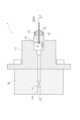
本実施形態に係るノズルヘッド1は、使用状態において、塗装ロボット(不図示)の作業アームに連結された本体部Bの、塗装ロボットに連結されている側の反対側に取り付けられる(図1、図2)。なお、図1および図2は、本体部Bおよびこれに取り付けられたノズルヘッド1の二方向からの断面図であり、両図の関係は各図中にII-II線(図1)およびI-I線(図2)で示している。[Configuration of Nozzle Head]
In use, the
本体部Bには、ノズルヘッド1内部の塗料室2と塗料供給元(不図示)とを接続する塗料供給路P1および塗料還送路P2が形成されている。また、塗料供給路P1および塗料還送路P2には、それぞれ、塗料供給路P1を開閉する供給側切換弁V1、および、塗料還送路P2を開閉する還送側切換弁V2、が設けられている。The main body B is formed with a paint supply passage P1 and a paint return passage P2 that connect the
ノズルヘッド1は、塗料室2、複数のノズル3、および電極4を備える。それぞれのノズル3は、基端31側において塗料室2と流体連通している(図1、図2)。また、複数のノズル3は、各ノズル3の先端32側に設けられた開口部32aが直線Xに沿って一本の直線状に配列するように設けられている(図1、図3)。なお、以降の説明において各部の方向について言及するときに、ノズルヘッド1のノズル3が設けられている側(図1および図2において紙面右側)を「前」(「前方」、「前部」など)とし、ノズルヘッド1の本体部Bと連結される側を「後」(「後方」、「後部」など)として説明する場合がある。The
静電霧化塗装機には、被塗物とノズルヘッド1との間に電位差を付与する電圧印加装置(不図示)が装備されており、塗料供給路P1、塗料室2、およびノズル3を経て噴出する塗料は、この電圧印加装置による高電圧印加により帯電状態になる。また、この電圧印加装置による高電圧印加によりノズル3の開口部32aの周りには電場が形成され、各の開口部32aから噴出された帯電状態の塗料は、いわゆる静電噴霧として、それぞれの開口部32aの周りに形成された電場の作用により微細化され、微細化した帯電状態の塗料は、ノズルヘッド1と被塗物との間の電位差により静電的に被塗物に引き寄せられて飛翔することで被塗物の表面に塗着する。The electrostatic atomizing paint coater is equipped with a voltage application device (not shown) that applies a potential difference between the workpiece and the
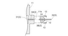
ノズルヘッド1は、塗料室2を含む第一部品11と、ノズル3の先端32を含む第二部品12とが、着脱自在な構造を有する(図4)。第一部品11と第二部品12とを連結するときは、固定用部品13を用いて第一部品11と第二部品12とを締結する。なお、固定用部品13を用いて第一部品11と第二部品12とを締結する方法は、機械部品の連結方法として公知の任意の方法を用いることができ、固定用部品13の構造およびこれに対応する第一部品11および第二部品12の部分構造は、採用される連結方法に対応した構造である。たとえば、嵌合構造、螺合構造などでありうる。The
ノズル3は、第一部品11に含まれる基端31側のノズル部分3Aと、第二部品12に含まれる先端32側のノズル部分3Bとに分割されており、第一部品11と第二部品12とを締結したときに、二つのノズル部分3A、3Bが連結されてノズル3を形成するようになっている(図5)。具体的には、第一部品11のノズル部分3Aの延長線上に設けられている空間11aに、第二部品12の基端側から突出したノズル部分3Bの一部33を収容でき、一部33を空間11aの奥まで挿入したときに二つのノズル部分3A、3Bが連結されるようになっている(図4)。The
(塗料室の構成)
塗料室2は、ノズルヘッド1の第一部品11の内部に、略直方体状の空間として設けられている(図1~図3)。塗料室2の前方側は複数のノズル3の基端31と流体連通しており、塗料室2の後方側は塗料供給路P1および塗料還送路P2と流体連通している。なお、塗料室2の内部には、ノズル3への塗料の流入量を制御可能な弁(不図示)が設けられている。当該弁は、複数のノズル3への塗料の流入量を一括して制御可能な一つまたは複数の弁であってもよいし、複数のノズル3のそれぞれへの塗料の流入量を個別に制御可能な複数の弁であってもよい。(Paint chamber configuration)
The
塗料室2の内部には、複数の開閉弁装置21が設けられている。それぞれの開閉弁装置21は、複数のノズル3のうちの一部または全部の基端31(以下、基端群と称する。)にわたって、当該基端群と塗料室との接続部分を閉鎖しうる弁体として実装されている。複数の開閉弁装置21は、各個別に、基端群と塗料室2との接続部分を閉鎖する姿勢と開放する姿勢とを選択できる。このような開閉弁装置21が設けられていることによって、塗装作業の中断や終了のために被塗物に対する塗料噴霧を停止する際に、開閉弁装置21を操作して基端群と塗料室2との接続部分を閉鎖することで、ノズル3から塗料が漏れることを防止できる。これによって、漏れた塗料によるノズルヘッド1周囲の汚染を回避できる。また、被塗物の端部を塗装する際には、複数のノズル3のうちの一部に相対する被塗物が存在しない場合がある。このような場合は、相対する被塗物が存在しないノズル3の基端31と塗料室2との接続部分を閉鎖することで、塗料の無駄な消費を回避できる。Inside the
(ノズルの構成)
本実施形態においてノズル3は、それぞれ、外径0.8mm、内径0.3mm、肉厚0.25mm、長さ60mmの直管として実装されている。ノズル3の寸法は、用いられる塗料の性質(溶剤の種類、粘度、固形分濃度など)や被塗物の大きさなどに応じて適宜選択されうる。ただし、ノズル3の内径は、0.2~1.0mmであることが好ましい。また、ノズル3の長さは、5~100mmであることが好ましい。(Nozzle configuration)
In this embodiment, the
本実施形態において、複数のノズル3は等間隔に設けられており、隣接するノズル3同士の離間距離は3mmである。なお、本実施形態では、直線Xに沿って100本のノズル3が互いに平行に設けられている。複数(100本)のノズル3が平行に設けられていることによって、各ノズル3から塗料液滴を平行に吐出させることができる。In this embodiment, the
本実施形態では、図1に示した第一ノズル34および第二ノズル35について、複数のノズル3の直線状の列が垂直方向と平行になるとき(複数のノズル3が延びる方向が水平になるとき)の、第一ノズル34と塗料室2との接続部分341における水頭である第一水頭と、第二ノズル35と塗料室2との接続部分351における水頭である第二水頭と、の差が、第二水頭の10%以内になるように構成されている。ここで、第一ノズル34は、複数のノズル3の直線状の列が垂直方向と平行になるとき(すなわち、図1および図2に示した姿勢をとるときである。)に、静電霧化塗装機の設置面を基準として最も高い位置に配置されるノズル3であり、第二ノズル35は、静電霧化塗装機の設置面を基準として最も低い位置に配置されるノズル3である。第一水頭と第二水頭との差を第二水頭の10%以内とする構成は、ノズル3の内径および長さ、ならびに配置を適切に選択することにより実現されうる。本実施形態では、外径0.8mm、内径0.3mm、長さ60mmの直管として実装されているノズル3が3mm間隔で直線状に配置されており、この構成により前述の水頭差が実現される。In this embodiment, the
また、ノズル3は、基端31側の第一部分36と、先端32側の第二部分37とを有する(図5)。本実施形態では、第一部分36は弱導電性樹脂製の長さ59mmの部分であり、第二部分37は絶縁樹脂製の長さ1mmの部分である。それぞれの部分を構成する材料から明らかなように、第一部分36はある程度の導電性を有するが、第二部分37は実質的に導電性を有さない。なお、第一部分36を構成する「弱導電性樹脂」とは、体積抵抗率が1012Ω・cm以下の樹脂材料をいう。ただし、第一部分36は、体積抵抗率が1012Ω・cm以下の任意の材料により構成されてよく、たとえば金属製であってもよい。なお、第一部分36は、より好ましくは体積抵抗率が108~1012Ω・cmの材料により構成される。また、第二部分37は、体積抵抗率が1014Ω・cm以上の任意の材料により構成されうる。 The
(電極の構成)
電極4は、複数のノズル3の直線状の列の各末端の延長線上に設けられている。すなわち、電極4は複数のノズル3と同様に直線Xに沿って設けられている。電極4は、金属製の直径0.8mmの丸棒として実装されており、導電体である。ただし、電極4を構成する材料は、体積抵抗率が1012Ω・cm以下の材料である限りにおいて任意であり、上記に例示した金属のほか、たとえば、弱導電性樹脂であってもよい。(Electrode configuration)
The
電極4は、直線Xに沿って第一ノズル34および第二ノズル35に隣接した位置に設けられている。電極4と、第一ノズル34および第二ノズル35との離間距離は3mmであり、ノズル3同士の離間距離と同じである。また、電極4の先端と複数のノズル3の先端32とは、実質的に同一平面上にある。すなわち、電極4が前方に延出する長さとノズル3が前方に延出する長さとを同一(60mm)にしてある。The
電極4の先端には、キャップ41が装着されている。キャップ41は、絶縁樹脂製、肉厚0.5mmの有底筒状体である。絶縁樹脂製であることから明らかなように、キャップ41は実質的に導電性を有さない。すなわち、電極4の先端は絶縁されている。なお、キャップ41を構成する材料および寸法は、電極4の先端を絶縁可能である限りにおいて任意である。A
〔ノズルヘッドの作用効果〕
続いて、上記の構成のノズルヘッド1によってもたらされる好ましい作用効果について説明する。[Function and effect of nozzle head]
Next, favorable effects brought about by the
本実施形態に係るノズルヘッド1では、複数のノズル3が直線状に配置されているため、複数のノズルが円環状に配置されている従来のノズルヘッドとは異なる塗装効果が得られる。具体的には、塗膜の厚さを均一にすることが容易である。ノズルが円環状に配置されたノズルヘッドを用いる場合、ノズルヘッドを被塗物に沿って掃引したときに、一本のノズルが通過する箇所と二本のノズルが通過する箇所とが発生するため、塗膜の厚さを均一にすることが難しい場合があった。ただし、複数のノズル3を直線状に配置する場合、これを円環状に配置する場合とは異なる課題が生じうる。In the
第一に、使用状態において複数のノズル3が位置する高さが異なることによって、ノズル3間の水頭差が問題となる。水頭差は、本実施形態のようにノズルが直線状に配置されたノズルヘッドにおいて特に問題になりやすい。これは、複数のノズルが直線状に配置されたノズルヘッドは、複数のノズルを円環状に配置したノズルヘッドと比べて、塗装幅を大きくした仕様が求められることが多く、直線状の配置の両端間の距離が円環状の配置の円の直径より大きくなり、これによって複数のノズル間の高低差が大きくなりやすいためである。ノズル3間の水頭差が大きい場合、塗料の吐出量がノズル3ごとに大きく異なる可能性があり、これは塗装ムラの発生につながる。そこで本実施形態では、水頭差が最大となる第一ノズル34と第二ノズル35とについて、第一水頭と第二水頭との差が第二水頭の10%以内となるように構成してあり、これによって、任意のノズル3間の水頭差を使用上問題とならない水準に抑制している。First, the head difference between the
第二に、各ノズル3を中心として形成される電場の均一性が問題となる。複数のノズルから帯電した塗料を吐出させてこれを被塗物に付着させる静電塗装方式の塗装を行うときに、各ノズルから塗料が吐出される態様(塗料液滴の大きさ、飛行方向など)を均一にして塗装品質の安定を図るべく、複数のノズルの電気的環境を均一にすることが必要になる。特に、ある特定のノズルを中心として形成される電場は、隣接する他のノズルを中心として形成される電場の影響を受けるため、複数のノズルの相対的な位置関係を均一にすることが通常行われる。複数のノズルを円環状に配置する従来のノズルヘッドの場合、ノズルを等間隔に配置すれば、いずれのノズルについても円周方向の両側に隣接する他のノズルが存在し、複数のノズルの相対的な位置関係が均一になるので、この問題の解消は容易である。Secondly, the uniformity of the electric field formed around each
しかし、本実施形態に係るノズルヘッド1では、第一ノズル34および第二ノズル35について、一方側にのみ隣接するノズル3が存在し、他方側にはノズル3が存在しない。そのため、第一ノズル34および第二ノズル35を中心として形成される電場が、他のノズル3を中心として形成される電場と大きく異なりうる。そこで本実施形態では、第一ノズル34および第二ノズル35のそれぞれに隣接して電極4を設け、これを隣接するノズル3の代替物として利用している。本実施形態において、ノズル3は外径0.8mmの直管であり、電極4は直径0.8mmの丸棒であるので、両者の電気的性質は実質的に同一視しうる。電極4を設けることによって、第一ノズル34および第二ノズル35を含めたすべてのノズル3の電気的環境を均一に近づけることができる。これによって、塗膜厚の均一性を高めることができる。However, in the
ただし、電極4を設けると、電極4の先端から生じる放電によって過電流異常が生じるおそれがある。そこで本実施形態では、電極4の先端にキャップ41を装着することによって、電極4の先端からの放電を抑制している。However, providing
以上のように、本実施形態に係るノズルヘッド1では、複数のノズル3を直線状に配置する場合に生じうる特有の課題を、未然に解決している。As described above, the
また、上記の構成のノズルヘッド1は、以下の作用効果ももたらす。なお、以下に挙げる作用効果は、ノズル3の配置が直線状である場合に限られずに発現する。In addition, the
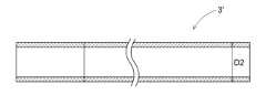
本実施形態に係るノズルヘッド1では、ノズル3の先端32側の第二部分37(長さ1mm)が実質的に導電性を有さない(図5)。これによって、ノズル3の先端32において塗料が流通する部分D1のみに電圧が印加されることになる。部分D1は、ノズル3の実体部分(肉厚0.25mm)を含まない。一方、先端を含むすべての部分が導電性を有する従来型ノズル3’(図6)では、従来型ノズル3’の外形に相当する部分D2にわたって電圧が印加されることになる。部分D2は、従来型ノズル3’の実体部分を含む。すなわち両者の違いは、電圧が印加される部分にノズルの実体部分を含むか否か、という点にある。静電塗装方式の塗装を行う際に電圧を印加する目的は、吐出される塗料液滴を帯電させることにあるので、ノズルの先端部分においてノズルの実体部分が帯電している必要はない。そこで本実施形態では、第二部分37が導電性を有さない構成によって、ノズル3の先端32において塗料液滴のみに不平等電界が集中するようにしてある。これによって、本実施形態に係るノズルヘッド1では、塗料液滴の帯電が効率よくなされており、従来のノズルヘッドに比べて塗料液滴を微細化する能力が向上している。In the
なお、ノズルヘッド1は本体部Bを介して電圧印加装置と接続されているため、ノズル3の基端31側に印加された高電圧が、先端32においてもできる限り低下しないことが求められる。ノズルの全体に実質的に導電性を有さない材料を用いた場合、ノズルの先端までの導電路が塗料のみとなり、塗料の電気抵抗に起因して電圧降下が生じる。そのため上記のように、ノズル3の先端32側のわずかな部分(第二部分37)のみに実質的に導電性を有さない材料を用いることが好適である。In addition, since the
加えて、ノズルヘッド1の各部のうち、複数の細管として実装されているノズル3は、摩耗、変形、破損などの不具合が特に生じやすい箇所である。本実施形態に係るノズルヘッド1は、塗料室2を含む第一部品11と、ノズル3の先端32を含む第二部品12とが、着脱自在な構造としてあるため、ノズル3に不具合が生じた場合に、第二部品12のみを交換して不具合を修繕できる。これによって、一体化された構成の従来のノズルヘッドに比べて、不具合の修繕が容易になる。In addition, among the various parts of the
〔その他の実施形態〕
最後に、本発明に係る静電霧化塗装機用ノズルヘッドのその他の実施形態について説明する。なお、以下のそれぞれの実施形態で開示される構成は、矛盾が生じない限り、他の実施形態で開示される構成と組み合わせて適用することも可能である。Other embodiments
Finally, other embodiments of the nozzle head for an electrostatic atomizer sprayer according to the present invention will be described. Note that the configurations disclosed in the following embodiments can be combined with the configurations disclosed in other embodiments as long as no contradiction occurs.
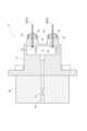
上記の実施形態では、複数のノズル3が、開口部32aが直線Xに沿って一本の直線状に配列するように設けられている構成を例として説明した。しかし本発明において、ノズルの列は単数であっても複数であってもよい。たとえば、図7に示す変形例に係るノズルヘッド1’では、ノズル3の列が二列設けられている。In the above embodiment, a configuration has been described in which
上記の実施形態では、塗料室2に複数の開閉弁装置21が設けられている構成を例として説明した。しかし、本発明において、開閉弁装置が設けられていなくてもよいし、複数のノズルの全てについて一括してノズルと塗料室との接続部分を開閉可能な単一の開閉弁装置が設けられていてもよい。In the above embodiment, a configuration in which multiple on-off
上記の実施形態では、ノズル3の先端32側の第二部分37が絶縁樹脂製である構成を例として説明した。しかし、本発明において、ノズルの先端が導電性を有していてもよく、すなわち、ノズルの先端の体積抵抗率が1012Ω・cm以下であってもよい。この場合、上記の実施形態とは異なり、全長にわたって同一の材料(体積抵抗率が1012Ω・cm以下の材料)で構成されたノズルを用いてもよい。 In the above embodiment, a configuration in which the
また、ノズルの先端に体積抵抗率が1014Ω・cm以上の材料からなる第二部分を設ける場合、その方法は上記の実施形態に限定されない。たとえば、図8に示したノズル3’ ’は、従来型ノズル3’(図6)の先端にノズルキャップ38を装着した構造を有する。ノズルキャップ38は体積抵抗率が1014Ω・cm以上の材料で形成された円環状の蓋体である。従来型ノズル3’にノズルキャップ38を装着することによって、従来型ノズル3’の部分は体積抵抗率が1012Ω・cm以下の材料からなる第一部分として働き、ノズルキャップ38の部分は体積抵抗率が1014Ω・cm以上の材料からなる第二部分として働く。この例においても、上記の実施形態に係るノズル3と同様に、塗料が流通する部分D1のみに電圧が印加することができる。また、ノズルキャップ38に、従来型ノズル3’の先端側面を覆う裾部分38aが設けられているので、従来型ノズル3’の該表面の絶縁される部分の長さが長く、高電圧を印加しても安定した塗装を実施できる。 In addition, when the tip of the nozzle is provided with a second portion made of a material having a volume resistivity of 1014 Ω·cm or more, the method is not limited to the above embodiment. For example, the
上記の実施形態では、第一水頭と第二水頭との差が、第二水頭の10%以内になるように構成されている例について説明した。しかし、本発明において、複数のノズル間の相互の水頭差は特に限定されない。In the above embodiment, an example was described in which the difference between the first water head and the second water head is configured to be within 10% of the second water head. However, in the present invention, the mutual water head difference between multiple nozzles is not particularly limited.
上記の実施形態では、複数のノズル3の直線状の列の各末端の延長線上に、電極4が設けられている構成を例として説明した。しかし本発明において、電極を設けなくてもよいし、複数のノズルの直線状の列の一部の末端の延長線上にのみ電極を設けてもよい。また、上記の実施形態では電極4が金属製の直径0.8mmの丸棒として実装されている構成を例として説明したが、電極の形状は特に限定されない。ただし、電極の外形形状と、ノズルの外形形状とを同一にすることが好ましい。In the above embodiment, an example has been described in which an
上記の実施形態では、電極4の先端にキャップ41が装着され、これによって電極4の先端が絶縁されている構成を例として説明した。しかし本発明において電極を設ける場合、その先端における絶縁の有無は限定されない。In the above embodiment, a
上記の実施形態では、電極4の前方への延出長さとノズル3の前方への延出長さとを同一にしてある構成を例として説明した。しかし、本発明において電極を設ける場合、その延出長さは、ノズルより短くてもよいし、長くてもよい。なお、電極の長さによって、塗料液滴の飛行方向を変更できるので、実現したい塗装パターンに応じて電極の長さを適宜選択するとよい。たとえば、電極を、その延出方向に沿って前後に移動可能な態様で装着すれば、実現したい塗装パターンに応じて電極の位置(延出長さ)を調節できる。また、長さが異なる複数の電極を用意するとともに、電極を着脱自在な態様で装着すれば、実現したい塗装パターンに応じて使用する電極の長さを選択できる。In the above embodiment, an example has been described in which the forward extension length of the
上記の実施形態では、ノズルヘッド1が、第一部品11と第二部品12とが着脱自在な構造を有する例について説明した。しかし、本発明に係る静電霧化塗装機用ノズルヘッドは、分離不能な一体ものの構造であってもよい。In the above embodiment, an example was described in which the
その他の構成に関しても、本明細書において開示された実施形態は全ての点で例示であって、本発明の範囲はそれらによって限定されることはないと理解されるべきである。当業者であれば、本発明の趣旨を逸脱しない範囲で、適宜改変が可能であることを容易に理解できるであろう。したがって、本発明の趣旨を逸脱しない範囲で改変された別の実施形態も、当然、本発明の範囲に含まれる。As for other configurations, it should be understood that the embodiments disclosed in this specification are illustrative in all respects and that the scope of the present invention is not limited thereto. Those skilled in the art will easily understand that appropriate modifications are possible without departing from the spirit of the present invention. Therefore, other embodiments that are modified without departing from the spirit of the present invention are naturally included in the scope of the present invention.
本発明は、たとえば、塗料噴霧により被塗物を塗装する静電霧化塗装機用のノズルヘッドに利用できる。The present invention can be used, for example, in a nozzle head for an electrostatic atomizing sprayer that paints a substrate by spraying paint.
1 :ノズルヘッド
11 :第一部品
11a :第一部品11に設けられた空間(ノズル部分3Bの一部33を収容可能である。)
12 :第二部品
13 :固定用部品
2 :塗料室
21 :開閉弁装置
3 :ノズル
3A :ノズル部分(基端側)
3B :ノズル部分(先端側)
31 :ノズル3の基端
32 :ノズル3の先端
32a :開口部
33 :ノズル部分3Bの一部(第一部品11の空間11aに収容されうる。)
34 :第一ノズル
341 :第一ノズル34と塗料室2との接続部分
35 :第二ノズル
351 :第二ノズル35と塗料室2との接続部分
36 :ノズル3の第一部分
37 :ノズル3の第二部分
38 :ノズルキャップ
4 :電極
41 :キャップ
B :本体部
P1 :塗料供給路
P2 :塗料還送路
V1 :供給側切換弁
V2 :還送側切換弁 1: nozzle head 11:
12: Second part 13: Fixing part 2: Paint chamber 21: Opening/closing valve device 3:
3B: Nozzle part (tip side)
31: Base end of
34: First nozzle 341: Connection portion between
Claims (5)
Translated fromJapanese前記塗料室と流体連通し先端の開口部から塗料を噴出する複数のノズルが直線状に配されたノズル列と、
前記ノズル列の延長線上であって前記ノズル列の両端と隣接して設けられた電極と、を備え、
前記電極の先端が絶縁されていることを特徴とする静電霧化塗装機用ノズルヘッド。 Paint roomand
a nozzle row including a plurality of nozzles arranged in a straight line, the nozzles being in fluid communication with the paint chamber and ejecting paint from an opening at the tip of the nozzle row;
electrodes provided on an extension of the nozzle row and adjacent to both ends of the nozzle row;
A nozzle head for an electrostatic atomizing coater, characterized in that the tip of the electrode is insulated .
Priority Applications (1)
| Application Number | Priority Date | Filing Date | Title |
|---|---|---|---|
| JP2020199744AJP7546462B2 (en) | 2020-12-01 | 2020-12-01 | Nozzle head for electrostatic atomizing paint machine |
Applications Claiming Priority (1)
| Application Number | Priority Date | Filing Date | Title |
|---|---|---|---|
| JP2020199744AJP7546462B2 (en) | 2020-12-01 | 2020-12-01 | Nozzle head for electrostatic atomizing paint machine |
Publications (2)
| Publication Number | Publication Date |
|---|---|
| JP2022087679A JP2022087679A (en) | 2022-06-13 |
| JP7546462B2true JP7546462B2 (en) | 2024-09-06 |
Family
ID=81975851
Family Applications (1)
| Application Number | Title | Priority Date | Filing Date |
|---|---|---|---|
| JP2020199744AActiveJP7546462B2 (en) | 2020-12-01 | 2020-12-01 | Nozzle head for electrostatic atomizing paint machine |
Country Status (1)
| Country | Link |
|---|---|
| JP (1) | JP7546462B2 (en) |
Families Citing this family (1)
| Publication number | Priority date | Publication date | Assignee | Title |
|---|---|---|---|---|
| JP7546463B2 (en) | 2020-12-01 | 2024-09-06 | 株式会社大気社 | Nozzle head for electrostatic atomizing paint machine |
Citations (7)
| Publication number | Priority date | Publication date | Assignee | Title |
|---|---|---|---|---|
| JP2003225591A (en) | 2002-02-05 | 2003-08-12 | Fuji Photo Film Co Ltd | Electrostatic coating apparatus and electrostatic coating method |
| CN1443095A (en) | 2000-05-16 | 2003-09-17 | 明尼苏达大学评议会 | Produces high-volume pellets with multi-nozzle jetting |
| JP2016512384A (en) | 2013-03-15 | 2016-04-25 | アプライド マテリアルズ インコーポレイテッドApplied Materials,Incorporated | Composite showerhead coating device using electrospray for lithium ion battery |
| JP2016068036A (en) | 2014-09-30 | 2016-05-09 | 東レエンジニアリング株式会社 | Electro-spray device |
| JP2017200672A (en) | 2016-05-02 | 2017-11-09 | アネスト岩田株式会社 | Electrostatic spraying equipment |
| WO2018096878A1 (en) | 2016-11-28 | 2018-05-31 | アネスト岩田株式会社 | Electrostatic spray device and electrostatic spray method |
| JP2022087680A (en) | 2020-12-01 | 2022-06-13 | 株式会社大気社 | Nozzle head for electrostatic atomization coater |
- 2020
- 2020-12-01JPJP2020199744Apatent/JP7546462B2/enactiveActive
Patent Citations (7)
| Publication number | Priority date | Publication date | Assignee | Title |
|---|---|---|---|---|
| CN1443095A (en) | 2000-05-16 | 2003-09-17 | 明尼苏达大学评议会 | Produces high-volume pellets with multi-nozzle jetting |
| JP2003225591A (en) | 2002-02-05 | 2003-08-12 | Fuji Photo Film Co Ltd | Electrostatic coating apparatus and electrostatic coating method |
| JP2016512384A (en) | 2013-03-15 | 2016-04-25 | アプライド マテリアルズ インコーポレイテッドApplied Materials,Incorporated | Composite showerhead coating device using electrospray for lithium ion battery |
| JP2016068036A (en) | 2014-09-30 | 2016-05-09 | 東レエンジニアリング株式会社 | Electro-spray device |
| JP2017200672A (en) | 2016-05-02 | 2017-11-09 | アネスト岩田株式会社 | Electrostatic spraying equipment |
| WO2018096878A1 (en) | 2016-11-28 | 2018-05-31 | アネスト岩田株式会社 | Electrostatic spray device and electrostatic spray method |
| JP2022087680A (en) | 2020-12-01 | 2022-06-13 | 株式会社大気社 | Nozzle head for electrostatic atomization coater |
Also Published As
| Publication number | Publication date |
|---|---|
| JP2022087679A (en) | 2022-06-13 |
Similar Documents
| Publication | Publication Date | Title |
|---|---|---|
| CN108212574B (en) | Coating head for applying a coating material to a surface to be coated and coating system comprising a coating head | |
| EP1911521B1 (en) | Electrostatic coating device | |
| EP1362640B1 (en) | Sprayer for electrostatic in-series coating of workpieces | |
| JP2006082064A (en) | Electrostatic coating equipment | |
| JP4445830B2 (en) | Electrostatic sprayer | |
| JPH03505842A (en) | Spraying equipment for both water-based and organic solvent paints | |
| JP7546462B2 (en) | Nozzle head for electrostatic atomizing paint machine | |
| JP7546463B2 (en) | Nozzle head for electrostatic atomizing paint machine | |
| US9724728B2 (en) | Electrostatic coating method | |
| US20070210191A1 (en) | Electrostatic rotary atomizer with indirect internal charge | |
| WO2006070938A1 (en) | Electrostatic coater | |
| JP6951573B2 (en) | Nozzle for painting | |
| KR20130024921A (en) | Electrostatic painting method and electrostatic paint gun | |
| JP5579515B2 (en) | Spray gun for electrostatic coating with counter electrode | |
| WO1996023591A1 (en) | Spray gun type electrostatic painting apparatus | |
| JP6672575B2 (en) | Electrostatic spraying device | |
| JP6944883B2 (en) | Nozzle for painting | |
| JP3424883B2 (en) | Spray gun type electrostatic coating equipment | |
| JP2555544Y2 (en) | Spray gun for painting | |
| JP2006205158A (en) | Electrostatic coater | |
| JP6871429B2 (en) | Painting equipment | |
| WO2024161810A1 (en) | Nozzle head for electrostatic atomization painting machine | |
| EP4613383A1 (en) | Coating device and coating method | |
| KR101009520B1 (en) | Electrostatic nozzle device for ship coating | |
| JP2007237089A (en) | Spray gun for powder electrostatic coating |
Legal Events
| Date | Code | Title | Description |
|---|---|---|---|
| A621 | Written request for application examination | Free format text:JAPANESE INTERMEDIATE CODE: A621 Effective date:20230808 | |
| A977 | Report on retrieval | Free format text:JAPANESE INTERMEDIATE CODE: A971007 Effective date:20240408 | |
| A131 | Notification of reasons for refusal | Free format text:JAPANESE INTERMEDIATE CODE: A131 Effective date:20240507 | |
| A521 | Request for written amendment filed | Free format text:JAPANESE INTERMEDIATE CODE: A523 Effective date:20240627 | |
| TRDD | Decision of grant or rejection written | ||
| A01 | Written decision to grant a patent or to grant a registration (utility model) | Free format text:JAPANESE INTERMEDIATE CODE: A01 Effective date:20240730 | |
| A61 | First payment of annual fees (during grant procedure) | Free format text:JAPANESE INTERMEDIATE CODE: A61 Effective date:20240827 | |
| R150 | Certificate of patent or registration of utility model | Ref document number:7546462 Country of ref document:JP Free format text:JAPANESE INTERMEDIATE CODE: R150 |