JP7545552B1 - Wheeled toy - Google Patents
Wheeled toyDownload PDFInfo
- Publication number
- JP7545552B1 JP7545552B1JP2023176931AJP2023176931AJP7545552B1JP 7545552 B1JP7545552 B1JP 7545552B1JP 2023176931 AJP2023176931 AJP 2023176931AJP 2023176931 AJP2023176931 AJP 2023176931AJP 7545552 B1JP7545552 B1JP 7545552B1
- Authority
- JP
- Japan
- Prior art keywords
- toy
- steering wheel
- wheel
- wheeled toy
- braking
- Prior art date
- Legal status (The legal status is an assumption and is not a legal conclusion. Google has not performed a legal analysis and makes no representation as to the accuracy of the status listed.)
- Active
Links
Images


Landscapes
- Toys (AREA)
Abstract
Translated fromJapaneseDescription
Translated fromJapanese本発明は、走行玩具に関し、さらに詳しくは、付勢力によって走行する車輪走行玩具に係わる。The present invention relates to a running toy, and more specifically to a wheeled running toy that runs on a biasing force.
従来、発射装置を用いて車輪走行玩具を付勢して発射させることが行われている(特許文献1)。この発射装置で用いられる車輪走行玩具としては、車輪の向きが直進方向に固定されたものが用いられていた。Conventionally, a launching device has been used to bias and launch a wheeled toy (Patent Document 1). The wheeled toy used in this launching device has wheels whose orientation is fixed in a straight line.
しかし、車輪の向きが直進方向に固定されたものでは、発射装置によって付勢された車輪走行玩具は直進方向に進むだけであり、直進方向以外の方向に進ませるには車輪走行玩具を強制案内するためのガイドレールを必要となる。
本発明は、かかる事情に鑑みなされたもので、付勢力によって走行可能な車輪走行玩具であって、車輪の向きの切替えによって自らベクトル方向とは異なる方向に進むことができる車輪走行玩具を提供することを目的としている。 However, if the orientation of the wheels is fixed in a straight line, the wheeled toy will only move in a straight line when biased by the launching device, and a guide rail is required to forcibly guide the wheeled toy in a direction other than the straight line.
The present invention has been developed in consideration of the above-mentioned circumstances, and aims to provide a wheeled toy that can run using a biasing force and can move in a direction different from its own vector direction by switching the direction of the wheels.
第1の手段は、
外力によって付勢されて走行可能な車輪走行玩具であって、
走行の際に路面に接地する接地部として、前記車輪走行玩具の進行方向を変える操舵輪と、前記路面に接地し速力を落とす制動部とが設けられ、
前記操舵輪の向きを前記外力のベクトル方向とは異なる向きに切り替えて固定可能な切替え機構が設けられ、
前記操舵輪として前二輪が設けられ、前記制動部として、前記ベクトル方向と異なる向きに切替え固定可能な後一輪が設けられている、ことを特徴とする車輪走行玩具である。 The first means is
A wheeled toy that can run when biased by an external force,
a steering wheel for changing a direction of travel of the wheel-running toy and a braking part for contacting the road surface to reduce a speed of the wheel-running toy,
a switching mechanism is provided thatcan switch and fix the direction of the steering wheel to a direction different from the vector direction of the external force;
This is a wheeled toy, characterized in that two front wheels are provided as the steering wheels, and one rear wheel is provided as the braking unit, which can be switched and fixed in a direction different from the vector direction .
第2の手段は、
外力によって付勢されて走行可能な車輪走行玩具であって、
走行の際に路面に接地する接地部として、前記車輪走行玩具の進行方向を変える操舵輪と、前記路面に接地し速力を落とす制動部とが設けられ、
前記操舵輪の向きを前記外力のベクトル方向とは異なる向きに切替え固定可能な切替え機構が設けられ、
前記操舵輪として後二輪が設けられ、前記制動部として、前記ベクトル方向と異なる向きに切替え固定可能な前一輪が設けられている、ことを特徴とする車輪走行玩具である。The second means is
A wheeled toy that can run when biased by an external force,
a steering wheel for changing a direction of travel of the wheel-running toy and a braking part for contacting the road surface to reduce a speed of the wheel-running toy,
a switching mechanism capable of switching and fixing the direction of the steering wheel to a direction different from the vector direction of the external force is provided;
This is a wheeled toy, characterized in that two rear wheels are provided as the steering wheels, and a front wheel that can be switched and fixed in a direction different from the vector direction is provided as the braking unit.
第3の手段は、第1又は第2の手段であって、
前記切替え機構は、前記操舵輪及び前記制動部の向きを前方と左右の各方向との間で選択的に切替え可能に構成されている、ことを特徴とする。The third means is the first or second means ,
The switching mechanism is configured to selectively switch the orientation of the steering wheel and the braking unit between a forward direction and a left/right direction.
第4の手段は、第3の手段であって、
前記操舵輪及び前記制動部のそれぞれは個別の支持体に支持され、各支持体は、上下方向に延在する個別の軸を中心に回動可能に構成され、
前記切替え機構は、操作レバーの回動運動を、前記操舵輪又は前記制動部の一方の支持体の回動を介して、前記操舵輪又は前記制動部の他方に伝達する、ことを特徴とする。The fourth means is the third means ,
The steering wheel and the brake unit are supported by separate supports, and each support is configured to be rotatable around a separate axis extending in a vertical direction;
The switching mechanism is characterized in that it transmits the rotational movement of the operating lever to the other of the steering wheel or the braking section via the rotation of a support for one of the steering wheel or the braking section.
第5の手段は、第4の手段であって、
前記操作レバーの操作部は、付勢のための打撃を受ける被打撃部を構成し、
前記被打撃部は、各切替え位置にあるときに玩具本体の真後ろを向く複数の被打撃面を有する、ことを特徴とする。The fifth means is the fourth means ,
The operating portion of the operating lever constitutes a striking portion that receives a striking force for biasing the operating portion,
The striking portion has a plurality of striking surfaces which face directly behindthe toy body when in each switching position.
第6の手段は、第5の手段であって、
前記切替え機構は、前記操舵輪及び前記制動部の向きを同じ向きに切替え可能に構成され、
操作部は、上下方向に延在する軸を中心に回動可能な前記操作レバーに形成され、玩具本体の後方に突出して設けられ、
切替えの際の前記操作部の向きと前記操舵輪及び前記制動部の向きとが互いに逆となっている、ことを特徴とする。The sixth means is the fifth means ,
The switching mechanism is configured to be able to switch the orientations of the steering wheel and the braking unit to the same orientation,
The operation part is formed on the operation lever which is rotatable around an axis extending in the vertical direction, and is provided so as to protrude rearward from the toy body,
The present invention is characterized in that the orientation of the operating unit and the orientation of the steering wheel and the braking unit at the time of switching are opposite to each other.
第7の手段は、第1又は第2の手段であって、
前記制動部の少なくとも外周は、前記操舵輪より摩擦力が大きくなっている、ことを特徴とする。The seventh means is the first or second means ,
At least an outer periphery of the braking portion has a frictional force greater than that of the steering wheel.
第1又は第2の手段によれば、車輪走行玩具は、左右の少なくとも一方に切り替えたときには、勢いが大きい間は外力のベクトル方向に直進し、勢いが弱まったときには車輪走行玩具は、操舵輪の向きに応じた方向に曲がる。According to the first or second means , when the wheeled toy is switched to at least one of the left and right sides, it moves straight in the vector direction of the external force while the momentum is strong, and when the momentum weakens, the wheeled toy turns in a direction according to the direction of the steering wheel.
第3の手段によれば、向きの切替えによって所望の方向に車両走行玩具を曲げることができるので、遊びの幅を広げることができる。According to the third aspect , the vehicle-running toy can be bent in a desired direction by switching the direction, thereby widening the scope of play.
第4の手段によれば、操作レバーの回動運動を、操舵輪又は制動部の一方の支持体の回動を介して、操舵輪又は制動部の他方に伝達するので、切替え機構の構成を簡素なものとすることができる。According to the fourth means , the rotational movement of the operating lever is transmitted to either the steering wheel or the braking section via the rotation of the support member of the other of the steering wheel or the braking section, so that the configuration of the switching mechanism can be simplified.
第5の手段によれば、各切替え位置で対応する打撃面が真後ろを向くので、いつでも前夫に向けて車輪走行玩具を発射させることができる。According to the fifth means , since the striking surface corresponding to each switching position faces directly backward, the wheeled toy can be launched toward the front man at any time.
第6の手段によれば、被打撃部の向きと操舵輪及び制動部の向きとを一致させることができる。According to the sixth aspect , the direction of the struck portion can be made to coincide with the direction of the steering wheel and the braking portion.
第7の手段によれば、操舵輪及び制動部が外力のベクトル方向と異なった向きとなっていると、発射させた車両走行玩具の勢いが弱くなったときに、制動部に強くブレーキが作
用するので、車輪走行玩具をドリフトしているかのように走行させることができる。According to the seventh means , if the steering wheel and the braking section are oriented in a direction different from the vector direction of the external force, when the momentum of the launched vehicle-running toy weakens, a strong brake is applied to the braking section, so that the wheel-running toy can be made to run as if it were drifting.
以下、本発明の実施形態を図面に基づいて説明する。The following describes an embodiment of the present invention with reference to the drawings.
《車輪走行玩具100の概略構成》
図1は、実施形態の車輪走行玩具100の斜視図、図2は、車輪走行玩具100の下面図である。なお、車輪走行玩具100の説明において、上下、左右、前後は、運転席から見た場合の上下、左右、前後を言うものとする(図1参照)。
車輪走行玩具100の玩具本体10には、ダミーの前二輪10a及び後二輪10bの4輪が設けられている。この前二輪10a及び後二輪10bは飾りの車輪であり路面に接地しない。
玩具本体10の下側の幅方向内側には、上記前二輪10aとは別の前二輪11aと、後一輪11bとが設けられている。この前二輪11a及び後一輪11bはリアル車輪となっていて路面に接地する。
また、玩具本体10の後部には、例えば発射装置200(図7参照)によって打撃される被打撃部12が設けられている。
また、被打撃部12は、同時に摘まみとなっていて、被打撃部12を摘まんで、被打撃部12を玩具本体10に対して左右に動かすと、前二輪11a及び後一輪11bが連動しその向きを変えて固定される。この前二輪11a及び後一輪11bの向きを変え被打撃部12を発射装置200によって打撃することで、発射された車輪走行玩具100がその走行態様を変化させる。<<Overall configuration of
Fig. 1 is a perspective view of a
Four wheels, namely, two dummy
Two
Further, at the rear of the
The struck
《細部構成》
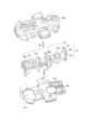
図3は、車輪走行玩具100の分解斜視図である。
(車輪走行玩具100の外観)
車輪走行玩具100の玩具本体10の外観は、車体下部フレーム20a及び車体上部フレーム20bからなる車体フレーム20と、前部カバー22と、後部カバー23とから構成されている。Detailed composition
FIG. 3 is an exploded perspective view of the
(Appearance of the wheeled toy 100)
The exterior of the
(前二輪11a及び後一輪11b)
車体フレーム20には、前二輪11aが、支持体25に支持され、且つ、車体下部フレーム20aの孔21aから下方に突出した状態で取り付けられている。支持体25は、上下方向に延在する軸25aを中心に回動可能となっている。
また、車体フレーム20には、後一輪11bが、支持体26に支持され、車体フレーム20の孔21bから下方に突出した状態で取り付けられている。支持体26は、上下方向に延在する軸26aを中心に回動可能となっている。
この場合、後一輪11bの少なくとも外周は、前二輪11aよりも路面に対する摩擦力が大きくなるように形成されていることが好ましい。例えば、全ての車輪がプラスチックで形成され、後一輪11bの外周に摩擦力の大きいゴムが被せられていることが好ましい。或いは、前二輪11aがプラスチックで形成され、後一輪11bは摩擦力の大きいゴムで形成されていることが好ましい。(Two
The two
Further, the
In this case, it is preferable that at least the outer periphery of the
(操作レバー27)
図4は、車体フレーム20の分解斜視図、図5は、切替え機構の分解斜視図である。
車体フレーム20の後部には、操作レバー27が設けられている。操作レバー27は、前後方向中間部で、上下方向に延在する軸27aを中心に回動可能に車体フレーム20に取り付けられている。操作レバー27の一部は車体フレーム20の後方に突出している。そして、操作レバー27のその突出部分には被打撃部12が形成されている。被打撃部12は、操作レバー27の本体から上下に張り出していて、その張出し部には、向きが異なる3つの被打撃面12a、12b、12cが形成されている。3つの被打撃面12a、12b、12cのいずれかが前二輪11a及び後一輪11bの各切替え位置で真後ろを向く。これにより、車輪走行玩具100は操作レバー27の切替え位置によらず同じ方向(直進方向)に発射させることができる。(Operation lever 27)
FIG. 4 is an exploded perspective view of the
An operating
(切替え機構30)
車体フレーム20の内部には、上記操作レバー27を含んで構成され、上記操作レバー27の操作によって前二輪11a及び後一輪11bの向きを切り替えて固定する切替え機構30が設けられている。(Switching Mechanism 30)
A
切替え機構30は、操作レバー27に係合する支持体26と、支持体26に係合する中間回動体31と、中間回動体31に係合する支持体25とを備えている。このうち中間回動体31は、上下方向に延在する軸31aを中心に回動可能に車体フレーム20に取り付けられている。The
操作レバー27と支持体26との係合は、操作レバー27の前端側下面に形成した溝27bに支持体26の上面に形成した凸部26bを入れ込むことによってなされている。
また、支持体26と中間回動体31との係合は、支持体26の下面に形成した凸部26cを中間回動体31の上面に形成した溝31bに入れ込むことによってなされている。
さらに、中間回動体31と支持体25との係合は、中間回動体31の上面に形成した凸部31cを支持体25の下面に形成した溝25bに入れ込むことによってなされている。 The
The
Furthermore, the intermediate
また、切替え機構30は、切替え位置で前二輪11aの向きを固定する固定手段を含んでいる、この固定手段は、支持体25に設けられた突起25cと、車体上部フレーム20bに設けられ各切替え位置で突起25cに係合する係合部(図示せず)とから構成されている。The
さらに、切替え機構30は、各切替えの際にクリック感を醸し出す弾性部材28を備えている。弾性部材28は、後一輪11bが前を向いた状態(中立状態)で支持体26の前端部を2つの弾性片28aで挟み込み、後一輪11bが左右に向きを変える際に、支持体26の前端部が対応する弾性片28aを弾いて乗り越える。また、後一輪11bが左又は右の向きから前となる場合には、支持体26の前端部が対応する弾性片28aを弾いて乗り越え中立状態に戻る。The
《実施形態の車輪走行玩具100の動作》
この車輪走行玩具100によれば、前二輪11a及び後一輪11bが前方を向いている状態では、発射装置200により発射されると、概ね、前方に向けて直進する。
また、前二輪11a及び後一輪11bの向きを左方又は右方とした場合には、発射装置200により発射された車輪走行玩具100は、発射の勢いで車輪走行玩具100が前二輪11a及び後一輪11bを滑らせながら、図6に示すように、先ずは前方に向けて直進し、勢いが弱まった所で、後一輪11bにブレーキがかかり、前二輪11aの向きに車輪走行玩具100が進むことになる。この場合、後一輪11bの摩擦力が大きいと、ブレーキがかかった後一輪11bを中心に前二輪11bの向きに車輪走行玩具100が進もうとするので、あたかも、ドリフト走行しているかの様相を呈する。Operation of the
According to this
In addition, when the two
《車輪走行玩具100の変形例》
上記車輪走行玩具100では、回動体(操作レバー27、支持体26、中間回動体31及び支持体25)において、隣り合う回動体同士を凸部と溝によって係合させ、操作レバー27の動力を支持体25、26に伝達するように構成したが、歯車機構その他の機構を介して支持体25、26に操作レバー27の動力を支持体25、26に伝達するように構成してもよい。<<Modification of the
In the above-mentioned
また、上記車輪走行玩具100では、被打撃部12を打撃することにより発射されるようにしたが、車輪走行玩具100は駆動ローラによって発射されるものであっても、発射装置を用いずに人手によって発射させるものでもよい。要は、何らかの外部の付勢力によって付勢されて走行するものであればよい。In addition, the
また、上記車輪走行玩具100では、旋回時の操舵輪として前二輪11a、制動部として機能する後一輪11bを設けたが、制動部は走行時に接地するリブであってもよい。このリブは固定されていてもよい。また、車両走行玩具100の前側がリブで後輪が操舵輪であってもよい。この場合、後輪(操舵輪)は一輪であってもよい。In addition, the
さらに、上記車輪走行玩具100では、旋回時の操舵輪として前二輪11a、制動部として機能する後一輪11bを設けたが、制動部として前一輪、旋回時の操舵輪として後二輪を設けてもよい。Furthermore, in the above-mentioned
また、上記車輪走行玩具100では、外力による付勢力によって走行するようになっていたが、フライホイールを内蔵し、外力によるフライホイールの回転によって付勢される車両走行玩具にも実施形態に係る車輪走行玩具100の技術を適用できる。In addition, while the
《発射装置200の概要》
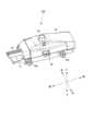
図7は、発射装置200の斜視図である。なお、発射装置200の説明において、上下、左右、前後は、同図に示した方向を言うものとする。
発射装置200の装置本体50の前部に設けられている打撃部材52を装置本体50内に所定量だけ押し込む。次に、装置本体50の前部の載置台51の上に車輪走行玩具100の後部を位置させる。
次に、装置本体50上の操作ボタン54を押下する。すると、車輪走行玩具100の後部の被打撃部12が発射装置200の打撃部材52によって打撃され、車輪走行玩具100が所定方向に発射される。
この場合、発射装置200がテーブルや床等に置かれていない場合には、操作ボタン54の押下が阻止される。Overview of
7 is a perspective view of launching
The striking
Next, the
In this case, when the
また、複数の発射装置200を横に並べて連結し、各打撃部材52を装置本体50内に所定量だけ押し込むとともに、各装置本体50の前部の載置台51の上に車輪走行玩具100の後部を位置させた後、いずれか1つの発射装置200の操作ボタン54を押すと、各車輪走行玩具100の後部の被打撃部12が各発射装置200の打撃部材52によって打撃され、複数の車輪走行玩具100が所定方向に一斉に発射される。
この場合、発射装置200がテーブルや床等に置かれていない場合には、操作ボタン54の押下自体が阻止される点は上記と同じである。 In addition, by connecting
In this case, if the
《詳細》
(打撃部材52)
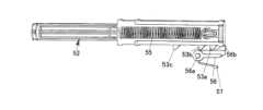
図8は、発射装置200の分解斜視図、図9は、発射装置200の内部構造を示す斜視図である。また、図10は、打撃部材52及び係止部材56の上面図、図11は、打撃部材52及び係止部材56の下面図である。
打撃部材52は、前後方向に往復動作可能に装置本体50に取り付けられている。打撃部材52は、コイルばね55によって前方に向けて付勢され、前端側の一部が装置本体50を貫通し、装置本体50の前方まで延出されている。なお、装置本体50の外郭は下部フレーム50aと上部フレーム50bから構成されている。
打撃部材52において、装置本体50内に位置する部分の左側面には、所定間隔で、上面視略鋸歯状の被係止爪53a、53b、53cが左方に張り出すようにして形成されている。被係止爪53(被係止爪53a、53b、53cの総称)は、上面視で、前側が打撃部材52から直立し、後側が傾斜している。"detail"
(Striking member 52)
Fig. 8 is an exploded perspective view of the
The striking
On the left side surface of the striking
(係止部材56)
また、打撃部材52の左隣には、係止部材56が設けられている。係止部材56は、上下方向に延在する軸56aを中心に回動可能に係止解除部材60の上に設けられている。この係止部材56の先端には爪56bが形成され、爪56bは、ばね部材57によって、打撃部材52に当接する方向(上面視時計方向)に付勢されている。
そして、打撃部材52が装置本体50に押し込まれた際に、被係止爪53の傾斜部が係止部材56の爪56bに当接される。すると、係止部材56がばね部材57の付勢力に抗して打撃部材52から離間する方向に回動する。そして、被係止爪53が爪56bを乗り越えると、係止部材56がばね部材57の付勢力によって初期位置に復帰する。この状態で打撃部材52から手を離すと、打撃部材52はコイルばね55の付勢力によって初期位置に戻ろうとするが、被係止爪53の直立部が係止部材56の爪56bに当たり、打撃部材52がその場所に保持される。これによって、打撃準備段階に至る。(Lock member 56)
Furthermore, a locking
When the striking
(係止解除部材60)
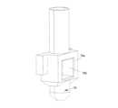
図12は、係止解除部材60の斜視図である。
係止解除部材60は、係止部材56による打撃部材52の係止を解除するものである。
係止解除部材60は、左右方向に長尺に構成されている。この係止解除部材60左右両端部は装置本体50から突出している。係止解除部材60は、コイルばね61によって右方に付勢され、常態では、右方位置(初期位置)にある。(Latch release member 60)
FIG. 12 is a perspective view of the unlocking
The
The
係止解除部材60には、上述のように係止部材56が設けられている。したがって、係止解除部材60が初期位置から左方に動作したときに、係止部材56も左方に移動し、係止部材56の爪56bが打撃部材52から離間する。これにより、係止部材56による打撃部材52の係止が解除される。As described above, the
係止解除部材60の上側には、発射のトリガとなる操作ボタン54と係合する鋸歯状の突出部60bが上方に突出して形成されている。突出部60bは、左側が直立部、右側が傾斜部となっている。一方、操作ボタン54の下端には、上記突出部60bに当接する鋸歯状の突出部54aが下方に突出して形成されている。突出部54aは、左側が傾斜部、右側が直立部となっている。そして、係止解除部材60の初期位置では、突出部60b及び突出部54aの先端部の傾斜部同士が当接している。これによって、初期状態で、操作ボタン54は上方に押し上げられている。そして、操作ボタン54を押下することで、突出部60b及び突出部54aの傾斜部同士が摺接し、係止解除部材60が左方に動作(移動)する。A sawtooth-shaped
なお、この係止解除部材60は、打撃部材52、係止部材56及び操作ボタン54を含んで発射機構を構成している。The
(ロック部材70)
図13は、発射装置200の下面側斜視図、図14は、ロック部材70の斜視図である。
ロック部材70は、発射機構をロックし、発射装置200が平面上に載置された時だけ発射機構のロックを解除して車輪走行玩具100の発射を許容するものである。(Locking Member 70)
FIG. 13 is a bottom perspective view of launching
The locking
ロック部材70は、装置本体50に対して所定範囲で上下動可能に設けられ、その下端側の一部が被入出部72から下方に突出して設けられている。
すなわち、装置本体50は、使用の際にテーブルと床等の平面に接する接地部71と段差を有し接地部71が当該平面に設置したときに当該平面と接地しない被入出部72を備えている。ロック部材70は、被入出部72の箇所で被入出部72に対して入出可能に設けられ、先端が接地部71を超えて延出する位置と、先端が接地部71に達しない位置との間で往復動作可能に構成され、コイルばね(図示せず)によって、被入出部72から突出する方向に付勢されている。このロック部材70は、人指による押込みが可能に構成され、押込みによって先端が接地部71に達しない位置まで動作するように構成されている。
このロック部材70は、発射装置200が平面上に載置されたとき、ロック部材70の下端が当該所定の平面に接触することになる。
なお、以下の説明では、ロック部材70が接地する突出位置を所定突出位置と言う。 The
That is, the device
When the
In the following description, the protruding position where the locking
ロック部材70は、装置本体50の内部で、係止解除部材60に係合している。
係止解除部材60には、突起部である被係止部60cが形成されている。一方、ロック部材70には、被係止部60cが当接可能な係止部70aが設けられている。係止部70aには、穴70bが形成されている。
ロック部材70は、所定突出位置以外にあるときに被係止部60cが係止部70aの穴70bの外側の縁部分に当接して係止解除部材60の左方への移動を阻止し、ロック部材70が所定突出位置にあるときには、被係止部60cが穴70bに入り込み当接を解除して係止解除部材60の左方への移動を許容する。 The locking
The unlocking
When the locking
(装置本体50の連結構造)
発射装置200には、隣り合う発射装置200の装置本体50同士を連結するための連結構造が設けられている。(Connection structure of device body 50)
The launching
装置本体50の左壁には、同一高さ位置に、左方に突出する膨出部50cが前後に1つずつ形成され、各膨出部50cの上側には穴50dが形成されている。一方、装置本体50の右壁には、膨出部50cよりも一段高い位置に、右方に突出する膨出部50eが前後に1つずつ形成され、各膨出部50eの下側には突起50fが形成されている。この突起50fと穴50dとが上下方向から嵌合されることにより、隣り合う発射装置200の装置本体50同士が連結される(図15)。The left wall of the
(係止解除部材60の連結構造)
発射装置200には、隣り合う係止解除部材60同士を連結させる連動構造が設けられている。この連結構造は、連結した複数の発射装置200からの車輪走行玩具100の発射を1つの操作ボタン54の操作によって行うためのものである。(Connection structure of unlocking member 60)
The
係止解除部材60の左端部は右端部よりも一段低くなっている。そして、係止解除部材60の左端部の上側には突起60dが形成され、右端部には、突起60dと嵌合可能な切欠き60eが形成されている。この切欠き60eと突起60dとが上下方向から嵌合されることにより、隣り合う発射装置200の係止解除部材60同士が連結される。この連結によって発射装置200が機能上で連結される(図15)。The left end of the unlocking
《実施形態の効果》
ロック部材70は、発射装置200がテーブル等の平面に載置されていない状態では、所定突出位置よりもロック部材70の先端が大きく突出するので、係止解除部材60の動作が阻止される。また、ロック部材70は、人手による押込みによって、所定突出位置を超えない位置まで動作するので、当該押込みによって所定突出位置でロック部材70を停止させるのは難しいことから、誤操作の恐れが少なくなる。Effects of the embodiment
When launching
また、発射装置200を並べて連結することができるので、車輪走行玩具100を一斉に発射させることができ、車輪走行玩具100間での競争を楽しむことができる。In addition, the launching
さらに、打撃部材52が3段階で係止されることから、遊びの幅を拡げることができる。Furthermore, the striking
《発射装置200の変形例》
上記発射装置200では、係止部材56を係止解除部材60上に設けたが、係止部材56を係止解除部材60とは独立して設けてもよい。Modifications of the
In the
また、上記発射装置200では、ロック部材70をコイルばね(図示せず)により突出方向に付勢したが、発射装置200の接地部71を下側にした場合にロック部材70の自重によってロック部材70が下動する構成としてもよい。In addition, in the above-mentioned
さらに、上記発射装置200では、係止解除部材60を別体の操作ボタン(操作部)54の押下によって動作させるようにしたが、係止解除部材200の一部を操作部としてもよい。Furthermore, in the above-mentioned
また、上記発射装置200で発射される対象を車輪走行玩具としたが、球体や、ペットボトルの蓋その他の発射装置にも適用可能である。In addition, the object launched by the
また、上記発射装置200では、係止解除部材60の動きを止めることで発射機構をロックし、係止解除部材60の動きを許容することで発射機構のロックを解除するようにしたが、係止解除部材60以外の部品、つまり、発射機構中のいずれかの部品(例えば、打撃部材52、コイルばね61、係止部材56又は操作ボタン54)の動作を止めることで、発射機構をロックし、係止解除部材60の動きを許容することで発射機構のロックを解除するようにしてもよい。In addition, in the above-mentioned
10 玩具本体
11a 前二輪
11b 後一輪
12 被打撃部
12a、12b、12c 被打撃面
25、26 支持体
27 操作レバー
50c 膨出部
50d 穴
50e 膨出部
50f 突起
52 打撃部材
53a、53b、53c 被係止爪
54 操作ボタン
54a 突出部
56 係止部材
56b 爪
60 係止解除部材
60c 被係止部
60d 突起
60e 切欠き
70 ロック部材
70a 係止部
70b 穴
71 接地部
72 被入出部
100 車輪走行玩具
200 発射装置10 Toy
Claims (7)
Translated fromJapanese走行の際に路面に接地する接地部として、前記車輪走行玩具の進行方向を変える操舵輪と、前記路面に接地し速力を落とす制動部とが設けられ、
前記操舵輪の向きを前記外力のベクトル方向とは異なる向きに切り替えて固定可能な切替え機構が設けられ、
前記操舵輪として前二輪が設けられ、前記制動部として、前記ベクトル方向と異なる向きに切替え固定可能な後一輪が設けられている、ことを特徴とする車輪走行玩具。 A wheeled toy that can run when biased by an external force,
a steering wheel for changing a direction of travel of the wheel-running toy and a braking part for contacting the road surface to reduce a speed of the wheel-running toy,
a switching mechanism is provided thatcan switch and fix the direction of the steering wheel to a direction different from the vector direction of the external force;
A wheeled toy, characterizedin that two front wheels are provided as the steering wheels, and one rear wheel is provided as the braking unit, which can be switched and fixed in a direction different from the vector direction.
走行の際に路面に接地する接地部として、前記車輪走行玩具の進行方向を変える操舵輪と、前記路面に接地し速力を落とす制動部とが設けられ、
前記操舵輪の向きを前記外力のベクトル方向とは異なる向きに切り替えて固定可能な切替え機構が設けられ、
前記操舵輪として後二輪が設けられ、前記制動部として、前記ベクトル方向と異なる向きに切替え固定可能な前一輪が設けられている、ことを特徴とする車輪走行玩具。A wheeled toy that can run when biased by an external force,
a steering wheel for changing a direction of travel of the wheel-running toy and a braking part for contacting the road surface to reduce a speed of the wheel-running toy,
a switching mechanism is provided that can switch and fix the direction of the steering wheel to a direction different from the vector direction of the external force;
A wheeled toy, characterized in that two rear wheels are provided as the steering wheels, and a front wheel that can be switched and fixed to a direction different from the vector direction is provided as the braking unit .
前記切替え機構は、操作レバーの回動運動を、前記操舵輪又は前記制動部の一方の支持体の回動を介して、前記操舵輪又は前記制動部の他方に伝達する、ことを特徴とする請求項3に記載の車輪走行玩具。 The steering wheel and the brake unit are supported by separate supports, and each support is configured to be rotatable around a separate axis extending in a vertical direction;
The wheeled toy accordingto claim 3 , characterized in that the switching mechanism transmits the rotational movement of the operating lever to the other of the steering wheel or the braking section via the rotation of a support body of one of the steering wheel or the braking section.
前記被打撃部は、各切替え位置にあるときに玩具本体の真後ろを向く複数の被打撃面を有する、ことを特徴とする請求項4に記載の車輪走行玩具。 The operating portion of the operating lever constitutes a striking portion that receives a striking force for biasing the operating portion,
5. The wheeled toy according toclaim 4 , wherein the striking portion has a plurality of striking surfaces which face directly rearward ofthe toy body when in each switching position.
操作部は、上下方向に延在する軸を中心に回動可能な前記操作レバーに形成され、玩具本体の後方に突出して設けられ、
切替えの際の前記操作レバーの回動方向と前記操舵輪及び前記制動部の回動方向とが互いに逆となっている、ことを特徴とする請求項5に記載の車輪走行玩具。 The switching mechanism is configured to be able to switch the orientations of the steering wheel and the braking unit to the same orientation,
The operation part is formed on the operation lever which is rotatable around an axis extending in the vertical direction, and is provided so as to protrude rearward from the toy body,
6. The wheeled toy according toclaim 5 , whereinthe rotation direction ofthe operating lever andthe rotation direction of the steering wheel and the braking portion at the time of switching are opposite to each other.
Priority Applications (1)
| Application Number | Priority Date | Filing Date | Title |
|---|---|---|---|
| JP2023176931AJP7545552B1 (en) | 2023-10-12 | 2023-10-12 | Wheeled toy |
Applications Claiming Priority (1)
| Application Number | Priority Date | Filing Date | Title |
|---|---|---|---|
| JP2023176931AJP7545552B1 (en) | 2023-10-12 | 2023-10-12 | Wheeled toy |
Publications (2)
| Publication Number | Publication Date |
|---|---|
| JP7545552B1true JP7545552B1 (en) | 2024-09-04 |
| JP2025067175A JP2025067175A (en) | 2025-04-24 |
Family
ID=92588249
Family Applications (1)
| Application Number | Title | Priority Date | Filing Date |
|---|---|---|---|
| JP2023176931AActiveJP7545552B1 (en) | 2023-10-12 | 2023-10-12 | Wheeled toy |
Country Status (1)
| Country | Link |
|---|---|
| JP (1) | JP7545552B1 (en) |
Citations (6)
| Publication number | Priority date | Publication date | Assignee | Title |
|---|---|---|---|---|
| US4498886A (en) | 1981-06-22 | 1985-02-12 | Adolph E. Goldfarb | Wheeled turbine-powered toy vehicle and launcher apparatus |
| US5316514A (en) | 1992-02-13 | 1994-05-31 | Matchbox Toys (Usa) Ltd. | Toy vehicle and launcher system |
| US5882241A (en) | 1997-01-22 | 1999-03-16 | Mullaney; Sean T. | Toy vehicle with movable front end |
| JP2006181266A (en) | 2004-12-28 | 2006-07-13 | Tomy Co Ltd | Small traveling toy system |
| JP2013223588A (en) | 2012-04-20 | 2013-10-31 | Takashimaya Co Ltd | Traveling body toy and traveling toy |
| JP2015024066A (en) | 2013-07-29 | 2015-02-05 | レック株式会社 | Traveling toy |
- 2023
- 2023-10-12JPJP2023176931Apatent/JP7545552B1/enactiveActive
Patent Citations (6)
| Publication number | Priority date | Publication date | Assignee | Title |
|---|---|---|---|---|
| US4498886A (en) | 1981-06-22 | 1985-02-12 | Adolph E. Goldfarb | Wheeled turbine-powered toy vehicle and launcher apparatus |
| US5316514A (en) | 1992-02-13 | 1994-05-31 | Matchbox Toys (Usa) Ltd. | Toy vehicle and launcher system |
| US5882241A (en) | 1997-01-22 | 1999-03-16 | Mullaney; Sean T. | Toy vehicle with movable front end |
| JP2006181266A (en) | 2004-12-28 | 2006-07-13 | Tomy Co Ltd | Small traveling toy system |
| JP2013223588A (en) | 2012-04-20 | 2013-10-31 | Takashimaya Co Ltd | Traveling body toy and traveling toy |
| JP2015024066A (en) | 2013-07-29 | 2015-02-05 | レック株式会社 | Traveling toy |
Also Published As
| Publication number | Publication date |
|---|---|
| JP2025067175A (en) | 2025-04-24 |
Similar Documents
| Publication | Publication Date | Title |
|---|---|---|
| US8298035B2 (en) | Track set for toy vehicles | |
| CA1184766A (en) | Toy vehicle accelerator | |
| RU2706821C1 (en) | Toy made with possibility to throw out an accessory | |
| KR101780143B1 (en) | Transformable toy with launcher | |
| US4556396A (en) | Stunt-performing toy vehicle | |
| JP7545552B1 (en) | Wheeled toy | |
| GB2136702A (en) | Toy vehicle launcher | |
| JP7749526B2 (en) | moving toys | |
| JP7482305B1 (en) | Launcher | |
| US20200360828A1 (en) | Toy vehicle launcher | |
| JP4588115B1 (en) | Traveling toy | |
| JP2011254988A (en) | Toy device | |
| CN212467141U (en) | Walking pushing shooting toy | |
| JP4920773B2 (en) | Vehicle toy | |
| US6830498B2 (en) | Toy game | |
| US7148434B2 (en) | Gearshift mechanism for electromotive toy car | |
| JP2001259246A (en) | Running toys | |
| CN110251958B (en) | Toy car capable of steering | |
| KR200175219Y1 (en) | Apparatus for shooting a ball in a toy robot | |
| JP2009247660A (en) | Automobile toy and blow unit | |
| CN110270105B (en) | Gyroscope assembly and toy with same | |
| JP3076468U (en) | Spherical launch toy | |
| CN112604312A (en) | Movable transformable toy and transformable toy assembly | |
| JP2006110274A (en) | Truck for toy vehicle, and toy vehicle | |
| JP2524440Y2 (en) | Simulator toy |
Legal Events
| Date | Code | Title | Description |
|---|---|---|---|
| A521 | Request for written amendment filed | Free format text:JAPANESE INTERMEDIATE CODE: A523 Effective date:20240222 | |
| A621 | Written request for application examination | Free format text:JAPANESE INTERMEDIATE CODE: A621 Effective date:20240222 | |
| A871 | Explanation of circumstances concerning accelerated examination | Free format text:JAPANESE INTERMEDIATE CODE: A871 Effective date:20240222 | |
| A131 | Notification of reasons for refusal | Free format text:JAPANESE INTERMEDIATE CODE: A131 Effective date:20240402 | |
| A601 | Written request for extension of time | Free format text:JAPANESE INTERMEDIATE CODE: A601 Effective date:20240510 | |
| A521 | Request for written amendment filed | Free format text:JAPANESE INTERMEDIATE CODE: A523 Effective date:20240731 | |
| TRDD | Decision of grant or rejection written | ||
| A01 | Written decision to grant a patent or to grant a registration (utility model) | Free format text:JAPANESE INTERMEDIATE CODE: A01 Effective date:20240806 | |
| A61 | First payment of annual fees (during grant procedure) | Free format text:JAPANESE INTERMEDIATE CODE: A61 Effective date:20240823 | |
| R150 | Certificate of patent or registration of utility model | Ref document number:7545552 Country of ref document:JP Free format text:JAPANESE INTERMEDIATE CODE: R150 |