JP7544877B2 - Aerosol Generation System with Planar Induction Coil - Google Patents
Aerosol Generation System with Planar Induction CoilDownload PDFInfo
- Publication number
- JP7544877B2 JP7544877B2JP2023001062AJP2023001062AJP7544877B2JP 7544877 B2JP7544877 B2JP 7544877B2JP 2023001062 AJP2023001062 AJP 2023001062AJP 2023001062 AJP2023001062 AJP 2023001062AJP 7544877 B2JP7544877 B2JP 7544877B2
- Authority
- JP
- Japan
- Prior art keywords
- flat spiral
- cartridge
- inductor coil
- spiral inductor
- aerosol
- Prior art date
- Legal status (The legal status is an assumption and is not a legal conclusion. Google has not performed a legal analysis and makes no representation as to the accuracy of the status listed.)
- Active
Links
- 239000000443aerosolSubstances0.000titleclaimsdescription91
- 230000006698inductionEffects0.000titledescription9
- 239000000758substrateSubstances0.000claimsdescription90
- 238000010438heat treatmentMethods0.000claimsdescription26
- 230000000391smoking effectEffects0.000claimsdescription8
- 238000000034methodMethods0.000claimsdescription6
- 239000012530fluidSubstances0.000claimsdescription5
- 239000000463materialSubstances0.000description72
- 239000007788liquidSubstances0.000description23
- 230000005291magnetic effectEffects0.000description15
- 238000010586diagramMethods0.000description9
- 239000000835fiberSubstances0.000description8
- 239000003990capacitorSubstances0.000description7
- 238000001514detection methodMethods0.000description7
- 230000007246mechanismEffects0.000description7
- 229910000859α-FeInorganic materials0.000description7
- 241000208125NicotianaSpecies0.000description5
- 235000002637Nicotiana tabacumNutrition0.000description5
- 230000005294ferromagnetic effectEffects0.000description5
- 230000001939inductive effectEffects0.000description5
- PUPZLCDOIYMWBV-UHFFFAOYSA-N(+/-)-1,3-ButanediolChemical compoundCC(O)CCOPUPZLCDOIYMWBV-UHFFFAOYSA-N0.000description4
- PEDCQBHIVMGVHV-UHFFFAOYSA-NGlycerineChemical compoundOCC(O)COPEDCQBHIVMGVHV-UHFFFAOYSA-N0.000description4
- 238000004519manufacturing processMethods0.000description4
- 230000035699permeabilityEffects0.000description4
- OKTJSMMVPCPJKN-UHFFFAOYSA-NCarbonChemical compound[C]OKTJSMMVPCPJKN-UHFFFAOYSA-N0.000description3
- 230000009471actionEffects0.000description3
- 150000001875compoundsChemical class0.000description3
- 239000003571electronic cigaretteSubstances0.000description3
- 239000010439graphiteSubstances0.000description3
- 229910002804graphiteInorganic materials0.000description3
- 239000012528membraneSubstances0.000description3
- -1polyethylenePolymers0.000description3
- 239000005020polyethylene terephthalateSubstances0.000description3
- 150000005846sugar alcoholsPolymers0.000description3
- 238000005979thermal decomposition reactionMethods0.000description3
- 230000007704transitionEffects0.000description3
- KMZHZAAOEWVPSE-UHFFFAOYSA-N2,3-dihydroxypropyl acetateChemical compoundCC(=O)OCC(O)COKMZHZAAOEWVPSE-UHFFFAOYSA-N0.000description2
- 239000010753BS 2869 Class ESubstances0.000description2
- 241000196324EmbryophytaSpecies0.000description2
- HBBGRARXTFLTSG-UHFFFAOYSA-NLithium ionChemical compound[Li+]HBBGRARXTFLTSG-UHFFFAOYSA-N0.000description2
- 229910019142PO4Inorganic materials0.000description2
- 230000004913activationEffects0.000description2
- 230000008901benefitEffects0.000description2
- 239000000919ceramicSubstances0.000description2
- 239000003795chemical substances by applicationSubstances0.000description2
- 235000019504cigarettesNutrition0.000description2
- 238000001816coolingMethods0.000description2
- 238000005260corrosionMethods0.000description2
- 230000007797corrosionEffects0.000description2
- ZDJFDFNNEAPGOP-UHFFFAOYSA-Ndimethyl tetradecanedioateChemical compoundCOC(=O)CCCCCCCCCCCCC(=O)OCZDJFDFNNEAPGOP-UHFFFAOYSA-N0.000description2
- 238000009826distributionMethods0.000description2
- 230000000694effectsEffects0.000description2
- 230000005669field effectEffects0.000description2
- 239000011888foilSubstances0.000description2
- 239000003365glass fiberSubstances0.000description2
- 235000011187glycerolNutrition0.000description2
- 230000020169heat generationEffects0.000description2
- 229920001903high density polyethylenePolymers0.000description2
- 239000004700high-density polyethyleneSubstances0.000description2
- 229910001416lithium ionInorganic materials0.000description2
- 239000000203mixtureSubstances0.000description2
- NBIIXXVUZAFLBC-UHFFFAOYSA-KphosphateChemical compound[O-]P([O-])([O-])=ONBIIXXVUZAFLBC-UHFFFAOYSA-K0.000description2
- 239000010452phosphateSubstances0.000description2
- 230000000704physical effectEffects0.000description2
- 229920000139polyethylene terephthalatePolymers0.000description2
- 239000007787solidSubstances0.000description2
- 125000006850spacer groupChemical group0.000description2
- 238000003860storageMethods0.000description2
- ZIBGPFATKBEMQZ-UHFFFAOYSA-Ntriethylene glycolChemical compoundOCCOCCOCCOZIBGPFATKBEMQZ-UHFFFAOYSA-N0.000description2
- 239000003039volatile agentSubstances0.000description2
- 238000004804windingMethods0.000description2
- RYGMFSIKBFXOCR-UHFFFAOYSA-NCopperChemical compound[Cu]RYGMFSIKBFXOCR-UHFFFAOYSA-N0.000description1
- UXDDRFCJKNROTO-UHFFFAOYSA-NGlycerol 1,2-diacetateChemical compoundCC(=O)OCC(CO)OC(C)=OUXDDRFCJKNROTO-UHFFFAOYSA-N0.000description1
- ZOKXTWBITQBERF-UHFFFAOYSA-NMolybdenumChemical compound[Mo]ZOKXTWBITQBERF-UHFFFAOYSA-N0.000description1
- 239000004698PolyethyleneSubstances0.000description1
- 239000004743PolypropyleneSubstances0.000description1
- 229910000831SteelInorganic materials0.000description1
- 229920004933Terylene®Polymers0.000description1
- 239000002253acidSubstances0.000description1
- 150000007513acidsChemical class0.000description1
- 239000000654additiveSubstances0.000description1
- 239000002386air freshenerSubstances0.000description1
- 125000001931aliphatic groupChemical group0.000description1
- 229910052782aluminiumInorganic materials0.000description1
- XAGFODPZIPBFFR-UHFFFAOYSA-NaluminiumChemical compound[Al]XAGFODPZIPBFFR-UHFFFAOYSA-N0.000description1
- 230000015572biosynthetic processEffects0.000description1
- 238000009835boilingMethods0.000description1
- 229920002301cellulose acetatePolymers0.000description1
- 230000008859changeEffects0.000description1
- 238000006243chemical reactionMethods0.000description1
- 235000019506cigarNutrition0.000description1
- 238000004140cleaningMethods0.000description1
- 239000011248coating agentSubstances0.000description1
- 238000000576coating methodMethods0.000description1
- 230000000295complement effectEffects0.000description1
- 238000010276constructionMethods0.000description1
- 229910052802copperInorganic materials0.000description1
- 239000010949copperSubstances0.000description1
- 230000008878couplingEffects0.000description1
- 238000010168coupling processMethods0.000description1
- 238000005859coupling reactionMethods0.000description1
- 238000005520cutting processMethods0.000description1
- 230000003111delayed effectEffects0.000description1
- 230000008021depositionEffects0.000description1
- IZMOTZDBVPMOFE-UHFFFAOYSA-Ndimethyl dodecanedioateChemical compoundCOC(=O)CCCCCCCCCCC(=O)OCIZMOTZDBVPMOFE-UHFFFAOYSA-N0.000description1
- 239000003814drugSubstances0.000description1
- 229940079593drugDrugs0.000description1
- 230000003670easy-to-cleanEffects0.000description1
- 150000002148estersChemical class0.000description1
- 239000003302ferromagnetic materialSubstances0.000description1
- 239000002657fibrous materialSubstances0.000description1
- 239000000796flavoring agentSubstances0.000description1
- 235000019634flavorsNutrition0.000description1
- 230000004907fluxEffects0.000description1
- 239000006261foam materialSubstances0.000description1
- 239000011796hollow space materialSubstances0.000description1
- 239000004615ingredientSubstances0.000description1
- 230000005381magnetic domainEffects0.000description1
- 230000005389magnetismEffects0.000description1
- 230000005499meniscusEffects0.000description1
- 229910052751metalInorganic materials0.000description1
- 239000002184metalSubstances0.000description1
- 229910044991metal oxideInorganic materials0.000description1
- 150000004706metal oxidesChemical class0.000description1
- 229910052750molybdenumInorganic materials0.000description1
- 239000011733molybdenumSubstances0.000description1
- 229910052758niobiumInorganic materials0.000description1
- 239000010955niobiumSubstances0.000description1
- GUCVJGMIXFAOAE-UHFFFAOYSA-Nniobium atomChemical compound[Nb]GUCVJGMIXFAOAE-UHFFFAOYSA-N0.000description1
- 229920001778nylonPolymers0.000description1
- 238000013021overheatingMethods0.000description1
- 230000005298paramagnetic effectEffects0.000description1
- 239000002907paramagnetic materialSubstances0.000description1
- 230000003071parasitic effectEffects0.000description1
- 230000021715photosynthesis, light harvestingEffects0.000description1
- 239000004033plasticSubstances0.000description1
- 229920003023plasticPolymers0.000description1
- 229920000728polyesterPolymers0.000description1
- 229920000573polyethylenePolymers0.000description1
- 229920000642polymerPolymers0.000description1
- 229920000098polyolefinPolymers0.000description1
- 229920001155polypropylenePolymers0.000description1
- 239000000843powderSubstances0.000description1
- 238000000197pyrolysisMethods0.000description1
- 230000005855radiationEffects0.000description1
- 230000009467reductionEffects0.000description1
- 230000000717retained effectEffects0.000description1
- 239000004065semiconductorSubstances0.000description1
- HBMJWWWQQXIZIP-UHFFFAOYSA-Nsilicon carbideChemical compound[Si+]#[C-]HBMJWWWQQXIZIP-UHFFFAOYSA-N0.000description1
- 229910010271silicon carbideInorganic materials0.000description1
- 239000000779smokeSubstances0.000description1
- 229910000679solderInorganic materials0.000description1
- 229910001220stainless steelInorganic materials0.000description1
- 239000010935stainless steelSubstances0.000description1
- 239000010959steelSubstances0.000description1
- ILJSQTXMGCGYMG-UHFFFAOYSA-Ntriacetic acidChemical compoundCC(=O)CC(=O)CC(O)=OILJSQTXMGCGYMG-UHFFFAOYSA-N0.000description1
- 230000008016vaporizationEffects0.000description1
Images


Classifications
- A—HUMAN NECESSITIES
- A24—TOBACCO; CIGARS; CIGARETTES; SIMULATED SMOKING DEVICES; SMOKERS' REQUISITES
- A24B—MANUFACTURE OR PREPARATION OF TOBACCO FOR SMOKING OR CHEWING; TOBACCO; SNUFF
- A24B15/00—Chemical features or treatment of tobacco; Tobacco substitutes, e.g. in liquid form
- A24B15/10—Chemical features of tobacco products or tobacco substitutes
- A24B15/16—Chemical features of tobacco products or tobacco substitutes of tobacco substitutes
- A24B15/167—Chemical features of tobacco products or tobacco substitutes of tobacco substitutes in liquid or vaporisable form, e.g. liquid compositions for electronic cigarettes
- A—HUMAN NECESSITIES
- A24—TOBACCO; CIGARS; CIGARETTES; SIMULATED SMOKING DEVICES; SMOKERS' REQUISITES
- A24F—SMOKERS' REQUISITES; MATCH BOXES; SIMULATED SMOKING DEVICES
- A24F40/00—Electrically operated smoking devices; Component parts thereof; Manufacture thereof; Maintenance or testing thereof; Charging means specially adapted therefor
- A24F40/40—Constructional details, e.g. connection of cartridges and battery parts
- A24F40/42—Cartridges or containers for inhalable precursors
- A—HUMAN NECESSITIES
- A24—TOBACCO; CIGARS; CIGARETTES; SIMULATED SMOKING DEVICES; SMOKERS' REQUISITES
- A24F—SMOKERS' REQUISITES; MATCH BOXES; SIMULATED SMOKING DEVICES
- A24F40/00—Electrically operated smoking devices; Component parts thereof; Manufacture thereof; Maintenance or testing thereof; Charging means specially adapted therefor
- A24F40/40—Constructional details, e.g. connection of cartridges and battery parts
- A24F40/46—Shape or structure of electric heating means
- A24F40/465—Shape or structure of electric heating means specially adapted for induction heating
- A—HUMAN NECESSITIES
- A24—TOBACCO; CIGARS; CIGARETTES; SIMULATED SMOKING DEVICES; SMOKERS' REQUISITES
- A24F—SMOKERS' REQUISITES; MATCH BOXES; SIMULATED SMOKING DEVICES
- A24F47/00—Smokers' requisites not otherwise provided for
- A—HUMAN NECESSITIES
- A24—TOBACCO; CIGARS; CIGARETTES; SIMULATED SMOKING DEVICES; SMOKERS' REQUISITES
- A24F—SMOKERS' REQUISITES; MATCH BOXES; SIMULATED SMOKING DEVICES
- A24F7/00—Mouthpieces for pipes; Mouthpieces for cigar or cigarette holders
- A—HUMAN NECESSITIES
- A61—MEDICAL OR VETERINARY SCIENCE; HYGIENE
- A61M—DEVICES FOR INTRODUCING MEDIA INTO, OR ONTO, THE BODY; DEVICES FOR TRANSDUCING BODY MEDIA OR FOR TAKING MEDIA FROM THE BODY; DEVICES FOR PRODUCING OR ENDING SLEEP OR STUPOR
- A61M15/00—Inhalators
- A61M15/06—Inhaling appliances shaped like cigars, cigarettes or pipes
- H—ELECTRICITY
- H05—ELECTRIC TECHNIQUES NOT OTHERWISE PROVIDED FOR
- H05B—ELECTRIC HEATING; ELECTRIC LIGHT SOURCES NOT OTHERWISE PROVIDED FOR; CIRCUIT ARRANGEMENTS FOR ELECTRIC LIGHT SOURCES, IN GENERAL
- H05B1/00—Details of electric heating devices
- H05B1/02—Automatic switching arrangements specially adapted to apparatus ; Control of heating devices
- H05B1/0227—Applications
- H05B1/023—Industrial applications
- H05B1/0244—Heating of fluids
- H—ELECTRICITY
- H05—ELECTRIC TECHNIQUES NOT OTHERWISE PROVIDED FOR
- H05B—ELECTRIC HEATING; ELECTRIC LIGHT SOURCES NOT OTHERWISE PROVIDED FOR; CIRCUIT ARRANGEMENTS FOR ELECTRIC LIGHT SOURCES, IN GENERAL
- H05B6/00—Heating by electric, magnetic or electromagnetic fields
- H05B6/02—Induction heating
- H05B6/10—Induction heating apparatus, other than furnaces, for specific applications
- H05B6/105—Induction heating apparatus, other than furnaces, for specific applications using a susceptor
- H—ELECTRICITY
- H05—ELECTRIC TECHNIQUES NOT OTHERWISE PROVIDED FOR
- H05B—ELECTRIC HEATING; ELECTRIC LIGHT SOURCES NOT OTHERWISE PROVIDED FOR; CIRCUIT ARRANGEMENTS FOR ELECTRIC LIGHT SOURCES, IN GENERAL
- H05B6/00—Heating by electric, magnetic or electromagnetic fields
- H05B6/02—Induction heating
- H05B6/36—Coil arrangements
- H05B6/365—Coil arrangements using supplementary conductive or ferromagnetic pieces
- A—HUMAN NECESSITIES
- A24—TOBACCO; CIGARS; CIGARETTES; SIMULATED SMOKING DEVICES; SMOKERS' REQUISITES
- A24F—SMOKERS' REQUISITES; MATCH BOXES; SIMULATED SMOKING DEVICES
- A24F40/00—Electrically operated smoking devices; Component parts thereof; Manufacture thereof; Maintenance or testing thereof; Charging means specially adapted therefor
- A24F40/10—Devices using liquid inhalable precursors
- H—ELECTRICITY
- H05—ELECTRIC TECHNIQUES NOT OTHERWISE PROVIDED FOR
- H05B—ELECTRIC HEATING; ELECTRIC LIGHT SOURCES NOT OTHERWISE PROVIDED FOR; CIRCUIT ARRANGEMENTS FOR ELECTRIC LIGHT SOURCES, IN GENERAL
- H05B2203/00—Aspects relating to Ohmic resistive heating covered by group H05B3/00
- H05B2203/021—Heaters specially adapted for heating liquids
Landscapes
- Electromagnetism (AREA)
- Physics & Mathematics (AREA)
- Health & Medical Sciences (AREA)
- Chemical & Material Sciences (AREA)
- General Chemical & Material Sciences (AREA)
- Chemical Kinetics & Catalysis (AREA)
- Engineering & Computer Science (AREA)
- Pulmonology (AREA)
- Veterinary Medicine (AREA)
- Hematology (AREA)
- Life Sciences & Earth Sciences (AREA)
- Animal Behavior & Ethology (AREA)
- General Health & Medical Sciences (AREA)
- Public Health (AREA)
- Heart & Thoracic Surgery (AREA)
- Biomedical Technology (AREA)
- Anesthesiology (AREA)
- Bioinformatics & Cheminformatics (AREA)
- General Induction Heating (AREA)
- Catching Or Destruction (AREA)
- Physical Vapour Deposition (AREA)
Description
Translated fromJapanese本開示はエアロゾル形成基体を加熱することにより作動するエアロゾル発生システムに関する。特に本発明は、電源を含む装置部分と、消耗品であるエアロゾル形成基体を含む交換可能なカートリッジ部分とを備えるエアロゾル発生システムに関連する。The present disclosure relates to an aerosol generating system that operates by heating an aerosol-forming substrate. In particular, the present invention relates to an aerosol generating system that includes a device portion that includes a power source and a replaceable cartridge portion that includes a consumable aerosol-forming substrate.
一つのタイプのエアロゾル発生システムは電子たばこである。電子たばこは一般に、気化されてエアロゾルを形成する液体エアロゾル形成基体を使用する。電子たばこは一般に、電源と、1回分の液体エアロゾル形成基体を保持するための液体貯蔵部分と、アトマイザーとを備える。One type of aerosol generating system is the electronic cigarette. Electronic cigarettes typically use a liquid aerosol-forming substrate that is vaporized to form an aerosol. Electronic cigarettes typically include a power source, a liquid reservoir for holding a dose of the liquid aerosol-forming substrate, and an atomizer.
液体エアロゾル形成基体は使用時に枯渇状態になり、そのため補充される必要がある。液体エアロゾル形成基体の詰め替え品を供給する最も一般的な方法は、カートマイザー型のカートリッジ入りである。カートマイザーは1回分の液体基体およびアトマイザーの両方を含み、通常はエアロゾル形成基体に浸された毛細管材料の周りに巻かれた電気的に動作する抵抗ヒーターの形態である。カートマイザーを単一のユニットとして交換することは、ユーザーにとって便利であるという利点があり、またユーザーが掃除またはその他の方法でアトマイザーを維持しなければならないという必要性が回避される。Liquid aerosol-forming substrates become depleted during use and therefore need to be replenished. The most common way of supplying refills of liquid aerosol-forming substrates is in cartomizer-type cartridges. A cartomizer contains both a dose of liquid substrate and an atomizer, usually in the form of an electrically operated resistive heater wrapped around a capillary material that is immersed in the aerosol-forming substrate. Replacing the cartomizer as a single unit has the advantage of convenience for the user and also avoids the need for the user to have to clean or otherwise maintain the atomizer.
しかし、現時点で入手できるカートマイザーよりも安価に製造でき堅牢性の高いエアロゾル形成基体の詰め替え品が許容されるシステムを提供できる一方で、なおも消費者にとって使用が簡単で便利であることが望ましい。さらに、はんだ付けされた継ぎ目の必要性がなく、清掃が簡単な密封された装置が許容されるシステムが提供されることが望ましい。However, it would be desirable to provide a system that is less expensive to manufacture and allows for more robust refills of the aerosol-forming substrate than currently available cartomizers, while still being simple and convenient for the consumer to use. Additionally, it would be desirable to provide a system that eliminates the need for soldered seams, allowing for a sealed device that is easy to clean.
第一の態様では、エアロゾル発生装置と、この装置で使用されるように構成されたカートリッジとを備える電気加熱式エアロゾル発生システムが提供され、この装置は、
装置ハウジングと、
フラットスパイラルインダクタコイルと、
フラットスパイラルインダクタコイルに接続され、かつ高周波振動電流をフラットスパイラルインダクタコイルに提供するように構成された電源と、を備え、
このカートリッジが、
エアロゾル形成基体を含み、かつ装置ハウジングを係合するように構成されたカートリッジハウジングと
エアロゾル形成基体を加熱するように位置するサセプタ素子と、を備える。 In a first aspect, there is provided an electrically heated aerosol generation system comprising an aerosol generation device and a cartridge configured for use with the device, the device comprising:
An apparatus housing;
A flat spiral inductor coil;
a power source connected to the flat spiral inductor coil and configured to provide a high frequency oscillating current to the flat spiral inductor coil;
This cartridge is
The cartridge housing includes an aerosol-forming substrate and is configured to engage the device housing; and a susceptor element positioned to heat the aerosol-forming substrate.
動作時に、高周波振動電流がフラットスパイラルインダクタコイルを通過して、サセプタ素子内で電圧を誘起する交番磁界を発生させる。誘起された電圧はサセプタ素子内に電流を流させ、この電流がサセプタ素子のジュール加熱を起こし、これが今度はエアロゾル形成基体を加熱する。サセプタ素子は強磁性である場合、サセプタ素子内のヒステリシス損失も熱を発生する場合がある。In operation, a high frequency oscillating current is passed through the flat spiral inductor coil to generate an alternating magnetic field that induces a voltage in the susceptor element. The induced voltage causes a current to flow in the susceptor element, which causes Joule heating of the susceptor element, which in turn heats the aerosol-forming substrate. If the susceptor element is ferromagnetic, hysteresis losses in the susceptor element can also generate heat.
「フラットスパイラルコイル」は本明細書で使用される時、一般的に平面のコイルで、コイルの巻線の軸がコイルのある表面に対して垂直であるコイルを意味する。いくつかの実施形態では、フラットスパイラルコイルは、平らなユークリッド平面内にあるという意味で平面状であってもよい。しかし、「フラットスパイラルコイル」という用語は本明細書で使用される時、曲面または他の3次元表面と一致するような形状のコイルも網羅する。例えば、フラットスパイラルコイルは、円筒ハウジングまたは装置のくぼみと一致する形状にされうる。その時フラットスパイラルコイルは「平面の」と呼ばれる可能性があるが、コイルの巻線の軸がコイルの中心で円筒面に垂直で、円筒面と一致する。フラットスパイラルコイルが円筒面または非ユークリッド平面と一致する場合、好ましくは、フラットスパイラルコイルはフラットスパイラルコイルの直径より大きいフラットスパイラルコイルの領域の曲率の半径を持つ平面内にある。フラットスパイラルコイルが、例えば円筒状または他の形状のハウジングと一致するように湾曲している時、サセプタ素子が相補的な形状を有するよりも望ましく、これによってフラットスパイラルコイルとサセプタとの間の距離はサセプタ素子の範囲全体で実質的に一定である。特にフラットスパイラルコイルとサセプタとの間に気流経路がある実施形態では、サセプタ素子とフラットスパイラルコイルとの間の最短距離は0.5~1mmであるのが好ましい。"Flat spiral coil" as used herein generally refers to a planar coil, where the axis of the coil windings is perpendicular to the surface on which the coil lies. In some embodiments, the flat spiral coil may be planar, in the sense that it lies in a flat Euclidean plane. However, the term "flat spiral coil", as used herein, also encompasses coils shaped to conform to curved or other three-dimensional surfaces. For example, the flat spiral coil may be shaped to conform to a cylindrical housing or cavity of a device. The flat spiral coil may then be called "planar", but the axis of the coil windings is perpendicular to the cylindrical surface at the center of the coil and coincides with the cylindrical surface. When the flat spiral coil conforms to a cylindrical surface or a non-Euclidean plane, preferably the flat spiral coil lies in a plane with a radius of curvature of the area of the flat spiral coil that is greater than the diameter of the flat spiral coil. When the flat spiral coil is curved, for example to conform to a cylindrical or other shaped housing, it is more desirable for the susceptor element to have a complementary shape, whereby the distance between the flat spiral coil and the susceptor is substantially constant throughout the extent of the susceptor element. In particular, in embodiments where there is an airflow path between the flat spiral coil and the susceptor, the minimum distance between the susceptor element and the flat spiral coil is preferably 0.5 to 1 mm.
高周波振動電流は本明細書で使用される時、500kHz~30MHzの周波数を持つ振動する電流を意味する。高周波振動電流の周波数は1~30MHzとすることができ、1~10 MHzであることが好ましく、5~7MHzであることがより好ましい。High frequency oscillating current, as used herein, means an oscillating current having a frequency between 500 kHz and 30 MHz. The frequency of the high frequency oscillating current can be between 1 and 30 MHz, preferably between 1 and 10 MHz, and more preferably between 5 and 7 MHz.
「サセプタ素子」は本明細書で使用される時、変動する磁場に晒された時に加熱する導体素子を意味する。これはサセプタ素子内で誘起された渦電流および/またはヒステリシス損失の結果でありうる。サセプタ素子のための可能性がある材料としては、黒鉛、モリブデン、炭化ケイ素、ステンレス鋼、ニオブ、アルミニウム、およびほとんどの任意の他の導電性元素が挙げられる。有利なことに、サセプタ素子はフェライト素子である。サセプタ素子の材料および幾何学的形状は、望ましい電気抵抗および発熱を提供するために選択できる。"Susceptor element" as used herein means a conductive element that heats up when exposed to a varying magnetic field. This may be the result of eddy currents and/or hysteresis losses induced within the susceptor element. Possible materials for the susceptor element include graphite, molybdenum, silicon carbide, stainless steel, niobium, aluminum, and almost any other conductive element. Advantageously, the susceptor element is a ferrite element. The material and geometry of the susceptor element can be selected to provide the desired electrical resistance and heat generation.
誘導加熱を利用したこの配列はカートリッジと装置の間に電気的な接点が一切形成される必要がないという利点を持つ。また、発熱体(この場合には、サセプタ素子)は、任意の他の構成要素にも電気結合されている必要がなく、はんだまたはその他の結合要素の必要性が除去される。さらに、単純で安価かつ堅牢なカートリッジの構成を可能にする装置の部品としてコイルが提供されている。カートリッジは作動に用いる装置よりもずっと大量に製造される一般に使い捨ての物品である。従って、より高価な装置を必要とする場合でも、カートリッジのコストを低減することは、製造者および消費者の両者にとって著しいコスト節約につながりうる。This arrangement utilizing induction heating has the advantage that no electrical contacts need to be made between the cartridge and the device. Also, the heating element (in this case the susceptor element) does not need to be electrically coupled to any other components, eliminating the need for solder or other bonding elements. Furthermore, the coil is provided as part of the device allowing for the construction of a simple, inexpensive and robust cartridge. Cartridges are generally disposable items manufactured in much larger quantities than the devices they operate with. Thus, reducing the cost of the cartridge, even when more expensive devices are required, can result in significant cost savings for both the manufacturer and the consumer.
さらに、コイルに関連する電力損失、特にコイルと装置の電力供給システムとの間の接続部での接触抵抗に起因する損失は誘導加熱システムに存在しないため、コイル設計ではなく誘導加熱の使用がエネルギー変換の改善を提供する。機能するために、コイルは恒久的または交換可能のいずれかで装置の中に提供されるリードを通して電源に接続される。改善した自動製造技法を用いてさえ、コイルシステムは、寄生損失を生成するリードにおいて一般に接触抵抗を有する。交換可能なコイル装置は、交換可能なカートリッジと装置のリードとの間の接触抵抗を増やすフィルムまたはその他の材料の堆積に苦しめられる場合がある。対照的に、誘導加熱システムは、発熱体と装置のリードとの間の接触を必要とせず、したがってコイルに基づく装置に存在する接触抵抗の問題に苦しめられることはない。Furthermore, the use of induction heating rather than coil design provides improved energy conversion since the power losses associated with the coil, particularly losses due to contact resistance at the connection between the coil and the device's power supply system, are not present in induction heating systems. To function, the coil is connected to a power source through leads that are provided in the device, either permanently or replaceably. Even with improved automated manufacturing techniques, coil systems generally have contact resistance in the leads that create parasitic losses. Replaceable coil devices may suffer from the deposition of films or other materials that increase the contact resistance between the replaceable cartridge and the device's leads. In contrast, induction heating systems do not require contact between the heating element and the device's leads and therefore do not suffer from the contact resistance problems present in coil-based devices.
フラットスパイラルコイルの使用により、堅牢でかつ製造が安価な単純なデザインを持つコンパクトな装置デザインが許容される。コイルはコイルへの付着物および腐食を防止でき、また装置の掃除を簡単にするように、装置ハウジング内に保持でき、また生成されたエアロゾルに晒される必要がない。また、フラットスパイラルコイルの使用により、装置とカートリッジの間の単純な境界面が許容され、単純かつ安価なカートリッジ設計ができるようになる。The use of a flat spiral coil allows for a compact device design with a simple design that is robust and inexpensive to manufacture. The coil can be retained within the device housing, preventing fouling and corrosion on the coil and facilitating cleaning of the device, and does not need to be exposed to the aerosols generated. The use of a flat spiral coil also allows for a simple interface between the device and cartridge, allowing for a simple and inexpensive cartridge design.
装置ハウジングは少なくともカートリッジの一部分を受けるためのくぼみを備え、そのくぼみは内部表面を持つ。フラットスパイラルインダクタコイルは電源に最も近いくぼみの表面上またはそれに隣接して配置されうる。フラットスパイラルコイルは、くぼみの内部表面と一致する形状としうる。The device housing includes a recess for receiving at least a portion of the cartridge, the recess having an interior surface. The flat spiral inductor coil may be disposed on or adjacent to a surface of the recess closest to the power source. The flat spiral coil may be shaped to conform to the interior surface of the recess.
装置ハウジングは本体およびマウスピース部分を備えうる。くぼみは本体内とすることができ、またマウスピース部分は出口を持つことができ、システムによって生成されたエアロゾルはその出口を通してユーザーの口へと引き出される。フラットスパイラルインダクタコイルはマウスピース部分内または本体内としうる。The device housing may include a body and a mouthpiece portion. The cavity may be in the body and the mouthpiece portion may have an outlet through which aerosol generated by the system is drawn into the user's mouth. The flat spiral inductor coil may be in the mouthpiece portion or in the body.
別の方法として、マウスピース部分はカートリッジの部品として提供されてもよい。マウスピース部分という用語は本明細書で使用される時、エアロゾル発生システムにより生成されたエアロゾルを直接吸い込むために、ユーザーの口に入れられる装置またはカートリッジの部分を意味する。エアロゾルはマウスピース部分を通してユーザーの口に運ばれる。Alternatively, the mouthpiece portion may be provided as part of the cartridge. As used herein, the term mouthpiece portion means the portion of the device or cartridge that is placed in the mouth of a user to directly inhale the aerosol generated by the aerosol generating system. The aerosol is delivered to the user's mouth through the mouthpiece portion.
システムは空気吸込み口から空気出口に延びる空気経路を備えうるが、ここで空気経路はフラットスパイラルインダクタを通過する。空気の流れがシステムを通してコイルを通過できるようにすることで、コンパクトなシステムを達成できる。The system may include an air path extending from an air inlet to an air outlet, where the air path passes through a flat spiral inductor. By allowing the air flow to pass through the coils through the system, a compact system can be achieved.
システムは、複数のインダクタコイルを含んでもよく、そのうちのいくつかまたは全てはフラットスパイラルコイルであってもよい。例えば、一つの可能な構成では、システムは、カートリッジを受ける装置ハウジング内のくぼみの反対側に配置された2つのフラットスパイラルコイルを備えうる。The system may include multiple inductor coils, some or all of which may be flat spiral coils. For example, in one possible configuration, the system may include two flat spiral coils positioned on opposite sides of a recess in the device housing that receives the cartridge.
フラットスパイラルインダクタはコイルの平面内で望ましい任意の形状を持たせることができる。例えば、フラットスパイラルコイルは円形形状を持つことも、一般的に長楕円形の形状を持つこともできる。コイルの直径は5mm~10mmとしうる。Flat spiral inductors can have any desired shape in the plane of the coil. For example, flat spiral coils can have a circular shape or a generally oblong shape. The coil diameter can be between 5 mm and 10 mm.
カートリッジは単純なデザインを持ちうる。カートリッジは、その内部にエアロゾル形成基体が保持されるハウジングを持つ。カートリッジハウジングは液体に対して不浸透性の材料を含む剛性のハウジングであることが好ましい。本明細書で使用される場合、「剛直なハウジング」とは、自立型のハウジングを意味する。The cartridge may have a simple design. The cartridge has a housing within which the aerosol-forming substrate is held. The cartridge housing is preferably a rigid housing comprising a material that is impermeable to liquids. As used herein, "rigid housing" means a free-standing housing.
エアロゾル形成基体はエアロゾルを形成できる揮発性化合物を放出する能力を持つ基体である。揮発性化合物はエアロゾル形成基体の加熱により放出されうる。エアロゾル形成基体は固体でも液体でもよく、固体および液体の両方の成分を含んでもよい。An aerosol-forming substrate is a substrate capable of releasing a volatile compound capable of forming an aerosol. The volatile compound may be released by heating the aerosol-forming substrate. The aerosol-forming substrate may be solid or liquid, or may contain both solid and liquid components.
エアロゾル形成基体は植物由来材料を含みうる。エアロゾル形成基体はたばこを含みうる。エアロゾル形成基体は加熱に伴いエアロゾル形成基体から放出される揮発性のたばこ風味化合物を含む、たばこ含有材料を含みうる。別の方法として、エアロゾル形成基体は非たばこ含有材料を含んでもよい。エアロゾル形成基体は均質化した植物由来材料を含んでもよい。エアロゾル形成基体は均質化したたばこ材料を含んでもよい。エアロゾル形成基体は少なくとも一つのエアロゾル形成剤を含んでもよい。エアロゾル形成剤は、使用において、密度の高い安定したエアロゾルの形成を容易にする、およびシステムの操作温度で熱分解に対して実質的に抵抗性のある任意の適切な公知の化合物または化合物の混合物である。好適なエアロゾル形成体は当業界で周知であり、多価アルコール(トリエチレングリコール、1,3-ブタンジオール、およびグリセリンなど)、多価アルコールのエステル(グリセロールモノアセテート、ジアセテート、またはトリアセテートなど)、およびモノカルボン酸、ジカルボン酸、またはポリカルボン酸の脂肪族エステル(ドデカン二酸ジメチルおよびテトラデカン二酸ジメチルなど)を含むが、これに限定されない。好ましいエアロゾル形成体は多価アルコールまたはその混合物(トリエチレングリコール、1,3-ブタンジオールおよびグリセリン(最も好ましい)など)である。エアロゾル形成基体は、その他の添加物および成分(風味剤など)を含みうる。The aerosol-forming substrate may comprise a plant-derived material. The aerosol-forming substrate may comprise tobacco. The aerosol-forming substrate may comprise a tobacco-containing material, including volatile tobacco flavour compounds that are released from the aerosol-forming substrate upon heating. Alternatively, the aerosol-forming substrate may comprise a non-tobacco-containing material. The aerosol-forming substrate may comprise a homogenized plant-derived material. The aerosol-forming substrate may comprise a homogenized tobacco material. The aerosol-forming substrate may comprise at least one aerosol-forming agent. The aerosol-forming agent is any suitable known compound or mixture of compounds that, in use, facilitates the formation of a dense, stable aerosol and is substantially resistant to thermal decomposition at the operating temperature of the system. Suitable aerosol formers are well known in the art and include, but are not limited to, polyhydric alcohols (such as triethylene glycol, 1,3-butanediol, and glycerin), esters of polyhydric alcohols (such as glycerol monoacetate, diacetate, or triacetate), and aliphatic esters of mono-, di-, or polycarboxylic acids (such as dimethyl dodecanedioate and dimethyl tetradecanedioate). Preferred aerosol formers are polyhydric alcohols or mixtures thereof (such as triethylene glycol, 1,3-butanediol, and glycerin (most preferred)). The aerosol-forming substrate may include other additives and ingredients, such as flavorings.
エアロゾル形成基体は、担体または支持体に吸着、被覆、含浸またはその他の方法で装填される場合がある。一例において、エアロゾル形成基体は毛細管材料内に保持される液体基体である。毛細管材料は繊維質または海綿状の構造を有する場合がある。毛細管材料は一束の毛細管を含むことが好ましい。例えば、毛細管材料は複数の繊維もしくは糸、またはその他の微細チューブを含む場合がある。繊維または糸は、一般的に液体をヒーターに移動するように整列されたものとしうる。別の方法として、毛細管材料は海綿体様または発泡体様の材料を含んでもよい。毛細管材料の構造は複数の小さな穴またはチューブを形成し、それを通して液体が毛細管作用によって移動できる。毛細管材料は適切な任意の素子または材料の組み合わせを含んでもよい。適切な材料の例としては、海綿体または発泡体材料、繊維または焼結粉末の形態のセラミック系またはグラファイト系の材料、発泡性の金属またはプラスチックの材料、例えば紡がれたかまたは押し出された繊維(酢酸セルロース、ポリエステル、または結合されたポリオレフィン、ポリエチレン、テリレンまたはポリプロピレン繊維、ナイロン繊維またはセラミックなど)でできた繊維性材料がある。毛細管材料は異なる液体物理特性で使用されるように、適切な任意の毛細管および空隙率を有する場合がある。液体は毛細管作用により毛細管材料を通過して移動できるようにする粘性、表面張力、密度、熱伝導率、沸点および蒸気圧を含むがこれに限定されない物理的特性を持つ。毛細管材料はエアロゾル形成基体をサセプタ素子に運ぶように構成されうる。The aerosol-forming substrate may be adsorbed, coated, impregnated or otherwise loaded onto a carrier or support. In one example, the aerosol-forming substrate is a liquid substrate held within a capillary material. The capillary material may have a fibrous or spongy structure. The capillary material preferably comprises a bundle of capillaries. For example, the capillary material may comprise a plurality of fibers or threads, or other fine tubes. The fibers or threads may be generally aligned to transport the liquid to the heater. Alternatively, the capillary material may comprise a sponge-like or foam-like material. The structure of the capillary material forms a plurality of small holes or tubes through which the liquid can travel by capillary action. The capillary material may comprise any suitable element or combination of materials. Examples of suitable materials include sponge or foam materials, ceramic or graphite-based materials in the form of fibers or sintered powders, expanded metal or plastic materials, fibrous materials such as spun or extruded fibers (such as cellulose acetate, polyester, or bonded polyolefin, polyethylene, terylene, or polypropylene fibers, nylon fibers, or ceramics). The capillary material may have any suitable capillary and porosity for use with different liquid physical properties. Liquids have physical properties including, but not limited to, viscosity, surface tension, density, thermal conductivity, boiling point, and vapor pressure that allow them to move through the capillary material by capillary action. The capillary material may be configured to convey the aerosol-forming substrate to the susceptor element.
サセプタ素子はエアロゾル形成基体と接触されうる。別の方法として、サセプタ素子はエアロゾル形成基体から離間されてもよいが、エアロゾル形成基体を加熱するためにエアロゾル形成基体の近くに配置されてもよい。The susceptor element may be in contact with the aerosol-forming substrate. Alternatively, the susceptor element may be spaced apart from the aerosol-forming substrate but positioned close to the aerosol-forming substrate to heat it.
サセプタ素子は、カートリッジハウジングが装置ハウジングと係合した時に、フラットスパイラルインダクタコイルに隣接して配置されるように構成されたカートリッジハウジングの壁上に提供されてもよい。使用時には、サセプタ素子で誘起される電圧を最大化するために、サセプタ素子をフラットスパイラルコイルの近くに配置させることが有利である。The susceptor element may be provided on a wall of the cartridge housing configured to be positioned adjacent to the flat spiral inductor coil when the cartridge housing is engaged with the device housing. In use, it is advantageous to have the susceptor element positioned close to the flat spiral coil to maximize the voltage induced in the susceptor element.
カートリッジハウジングが装置ハウジングと係合した時、フラットスパイラルインダクタコイルとサセプタ素子の間に気流通路を提供しうる。気化したエアロゾル形成基体は気流通路内の空気の流れに混入させることができ、その後、冷めてエアロゾルを形成する。When the cartridge housing is engaged with the device housing, it can provide an airflow passage between the flat spiral inductor coil and the susceptor element. The vaporized aerosol-forming substrate can be entrained in the airflow passage and then cooled to form an aerosol.
サセプタ素子は、メッシュ、フラットスパイラルコイル、内側フォイル、繊維、またはロッドを備えてもよい。サセプタ素子は、液体エアロゾル形成基体または気化したエアロゾル形成基体がサセプタを通過しうるように流体浸透性としうる。The susceptor element may comprise a mesh, a flat spiral coil, an inner foil, a fiber, or a rod. The susceptor element may be fluid permeable to allow the liquid aerosol-forming substrate or the vaporized aerosol-forming substrate to pass through the susceptor.
カートリッジ内に毛細管材料が使用される場合(例えば、サセプタがメッシュまたはフィラメントの配列の形態である場合)、毛細管材料はサセプタ内の隙間の中へと延びる場合がある。サセプタ素子はシートの形態で提供されてもよく、カートリッジハウジング内の開口部を横切って延びうる。別の方法として、サセプタ素子はエアロゾル形成基体に埋め込まれてもよい。Where capillary material is used within the cartridge (e.g. where the susceptor is in the form of a mesh or filament array), the capillary material may extend into gaps within the susceptor. The susceptor elements may be provided in the form of sheets and may extend across an opening in the cartridge housing. Alternatively, the susceptor elements may be embedded in the aerosol-forming substrate.
サセプタ素子は毛細管材料を含んでもよい。サセプタは、システムを通る空気経路を横切って延びる毛細管芯を含んでもよい。The susceptor element may include a capillary material. The susceptor may include a capillary wick that extends across an air path through the system.
有利なことに、サセプタ素子は1~40000の相対浸透性を持つ。大半の加熱のために渦電流に依存することが望ましい時には低めの浸透性の材料を使用してもよく、またヒステリシス効果が望ましい時には高めの浸透性の材料を使用してもよい。材料の相対浸透性は500~40000であることが好ましい。これにより効率的な加熱が提供される。Advantageously, the susceptor elements have a relative permeability of 1 to 40,000. A lower permeability material may be used when it is desired to rely on eddy currents for the majority of the heating, and a higher permeability material may be used when a hysteresis effect is desired. The relative permeability of the material is preferably 500 to 40,000. This provides efficient heating.
サセプタ素子の材料は、そのキュリー温度を理由に選択してもよい。そのキュリー温度を超えるとヒステリシス損失がもはや発生しないため、材料はもはや強磁性ではなくなり、そのため加熱されなくなる。サセプタ素子が単一の材料でできている場合、キュリー温度はサセプタ素子が持つべき最高温度に対応しうる(すなわち、キュリー温度はサセプタ素子が加熱されるべき最高温度と等しいか、またはこの最高温度から約1~3%だけ逸脱した温度である)。これにより、急激な過熱の可能性が低減される。The material of the susceptor element may be selected because of its Curie temperature, above which hysteresis losses no longer occur and the material is no longer ferromagnetic and therefore does not heat up. If the susceptor element is made of a single material, the Curie temperature may correspond to the maximum temperature the susceptor element should have (i.e., the Curie temperature is equal to the maximum temperature to which the susceptor element should be heated or deviates from this maximum temperature by about 1-3%). This reduces the possibility of sudden overheating.
サセプタ素子が複数の材料でできている場合、サセプタ素子の材料はさらなる態様に関して最適化できる。例えば材料は、サセプタ素子の第一の材料がサセプタ素子が加熱されるべき最高温度を超えるキュリー温度を持ちうるように選択できる。その後、サセプタ素子のこの第一の材料は、例えば最大発熱に関して最適化し、一方でエアロゾル形成基体に移動して、サセプタの効率的な加熱が提供されるようにしうる。ところが、サセプタ素子はその後、追加的にサセプタが加熱されるべき最高温度に対応するキュリー温度を持つ第二の材料を備えることができ、サセプタ素子がこのキュリー温度に達すると、サセプタ素子全体の磁性が変化する。この変化は検出されてマイクロコントローラに通信されることができ、その後、温度が再びキュリー温度よりも低い温度まで冷めるまでAC電力の発生が妨害され、冷めた後でAC電力の発生が再開される。If the susceptor element is made of multiple materials, the materials of the susceptor element can be optimized for further aspects. For example, materials can be selected such that a first material of the susceptor element can have a Curie temperature that exceeds the maximum temperature to which the susceptor element should be heated. This first material of the susceptor element can then be optimized, for example, for maximum heat generation while being transferred to the aerosol-forming substrate, so that efficient heating of the susceptor is provided. However, the susceptor element can then additionally comprise a second material with a Curie temperature that corresponds to the maximum temperature to which the susceptor should be heated, and when the susceptor element reaches this Curie temperature, the magnetism of the entire susceptor element changes. This change can be detected and communicated to the microcontroller, after which the generation of AC power is interrupted until the temperature cools down again below the Curie temperature, after which the generation of AC power is resumed.
システムは電気的に作動する喫煙システムとしうる。システムは手持ち式のエアロゾル発生システムでもよい。エアロゾル発生システムは従来型の葉巻たばこや紙巻たばこと匹敵するサイズを持ちうる。喫煙システムの全長は、およそ30mm~およそ150mmとしうる。喫煙システムの外径は、およそ5mm~およそ30mmとしうる。The system may be an electrically operated smoking system. The system may be a handheld aerosol generating system. The aerosol generating system may have a size comparable to a conventional cigar or cigarette. The overall length of the smoking system may be from about 30 mm to about 150 mm. The outer diameter of the smoking system may be from about 5 mm to about 30 mm.
システムはさらに、インダクタコイルおよび電源に接続された電気回路を備えうる。電気回路はマイクロプロセッサを備えうるが、これはプログラマブルマイクロプロセッサ、マイクロコントローラ、または特定用途向けICチップ(ASIC)または制御能力を持つその他の電子回路としうる。電気回路はさらなる電子構成要素を備えうる。電気回路はフラットスパイラルコイルへの電流供給を調節するよう構成しうる。電流はシステムの起動後、フラットスパイラルコイル素子に連続的に供給されてもよく、または毎回の吸入ごとのように断続的に供給されてもよい。電気回路は有利なことにDC/ACインバータを備えることができ、これはクラスDまたはクラスEの電力増幅器を備えうる。The system may further comprise an electrical circuit connected to the inductor coil and to a power source. The electrical circuit may comprise a microprocessor, which may be a programmable microprocessor, a microcontroller, or an application specific integrated circuit chip (ASIC) or other electronic circuit with control capabilities. The electrical circuit may comprise further electronic components. The electrical circuit may be configured to regulate the current supply to the flat spiral coil. Current may be supplied to the flat spiral coil element continuously after activation of the system, or may be supplied intermittently, such as with every inhalation. The electrical circuit may advantageously comprise a DC/AC inverter, which may comprise a class D or class E power amplifier.
システムはハウジングの本体内に電源(一般にリチウムイオンリン酸型電池などの電源)を備えることが有利である。別の方法として、電源はコンデンサーなど別の形態の電荷蓄積装置としうる。電源は再充電を要するものとしてもよく、例えば1回以上の喫煙の体験などの1回以上のユーザー操作のために十分なエネルギーの蓄積が許容される容量を持ちうる。例えば、電源は従来型の紙巻たばこ1本を喫煙するのにかかる一般的な時間に対応する約6分の時間、または6分の倍数の時間にわたるエアロゾルの連続的な生成を許容するのに十分な容量を持ちうる。別の例では、電源は所定回数の喫煙、またはフラットスパイラルコイルの不連続的な起動を許容する十分な容量を持ちうる。Advantageously, the system includes a power source (typically a lithium ion phosphate battery or other power source) within the body of the housing. Alternatively, the power source may be another form of charge storage device, such as a capacitor. The power source may require recharging and may have a capacity that allows for the storage of sufficient energy for one or more user actions, such as one or more smoking experiences. For example, the power source may have a capacity sufficient to allow for continuous generation of aerosol for a period of approximately six minutes, corresponding to the typical time it takes to smoke one conventional cigarette, or a multiple of six minutes. In another example, the power source may have a capacity sufficient to allow for a predetermined number of smokes, or for discontinuous activation of the flat spiral coil.
第二の態様では、電気加熱式エアロゾル発生装置が提供され、この装置は、
カートリッジの少なくとも一部分を受けるためのくぼみを画定し、カートリッジがエアロゾル形成基体およびエアロゾル形成基体と接触するサセプタ素子を含む装置ハウジングを備え、くぼみが内部表面を持つ、装置ハウジングと、
くぼみの内部表面上に配置されるフラットスパイラルインダクタコイルと、
フラットスパイラルインダクタコイルに接続され、かつ高周波振動電流をフラットスパイラルインダクタコイルに提供するように構成された電源と、を備える。 In a second aspect, there is provided an electrically heated aerosol generating device comprising:
an apparatus housing defining a cavity for receiving at least a portion of a cartridge, the cartridge including an aerosol-forming substrate and a susceptor element in contact with the aerosol-forming substrate, the cavity having an interior surface;
a flat spiral inductor coil disposed on an interior surface of the recess;
a power supply connected to the flat spiral inductor coil and configured to provide a high frequency oscillating current to the flat spiral inductor coil.
第三の態様は、エアロゾルを発生する方法が提供され、この方法は、
サセプタと、サセプタに接触またはサセプタに近接するエアロゾル形成基体と、を備えるカートリッジを提供することと、
サセプタがフラットスパイラルインダクタコイルに近接するようにカートリッジを配置することと、
フラットスパイラル誘導コイルを通して高周波振動電流を通過させてサセプタ内に電流を誘起し、これによってエアロゾル形成基体を加熱することと、を含む。 In a third aspect, a method of generating an aerosol is provided, the method comprising:
providing a cartridge comprising a susceptor and an aerosol-forming substrate in contact with or adjacent to the susceptor;
positioning the cartridge such that the susceptor is adjacent to a flat spiral inductor coil;
and passing a high frequency oscillating current through a flat spiral induction coil to induce electrical currents in the susceptor, thereby heating the aerosol-forming substrate.
一つの態様に関連して説明した特徴は本開示の他の態様に適用されうる。特に、本開示の第一の態様に関連して説明した有利なまたは随意的な特徴は本発明の第二のおよび第三の態様に適用されうる。Features described in relation to one aspect may be applied to other aspects of the present disclosure. In particular, advantageous or optional features described in relation to the first aspect of the present disclosure may be applied to the second and third aspects of the invention.
ここで本開示によるシステムの実施形態を、以下の添付図面を参照しながら、例証としてのみではあるが詳細に説明する。Embodiments of systems according to the present disclosure will now be described in detail, by way of example only, with reference to the accompanying drawings in which:
図に示す実施形態はすべて誘導加熱に依存する。誘導加熱は時間的に変化する磁場内に加熱される導電性の物品を配置することで機能する。渦電流は導電性の物品内で誘起される。導電性の物品が電気的に孤立されている場合、渦電流は導電性の物品のジュール加熱により分散される。エアロゾル形成基体を加熱することにより動作するエアロゾル発生システムで、エアロゾル形成基体そのものは一般に、そのような方法で誘導加熱されるのに十分な導電性を備えているとはいえない。そのため、図に示す実施形態で、サセプタ素子は加熱される導電性の物品として使用されてから、エアロゾル形成基体がサセプタ素子によって熱伝導、熱対流および/または熱放射により加熱される。強磁性のサセプタ素子が使用される場合、熱は磁区がサセプタ素子内で切り換わる時にヒステリシス損失によっても発生しうる。All of the illustrated embodiments rely on induction heating. Induction heating works by placing a conductive article to be heated in a time-varying magnetic field. Eddy currents are induced in the conductive article. If the conductive article is electrically isolated, the eddy currents are dispersed by Joule heating of the conductive article. In aerosol generating systems that operate by heating an aerosol-forming substrate, the aerosol-forming substrate itself is generally not sufficiently conductive to be inductively heated in such a manner. Therefore, in the illustrated embodiments, a susceptor element is used as the conductive article to be heated, and the aerosol-forming substrate is then heated by the susceptor element through thermal conduction, thermal convection and/or thermal radiation. If a ferromagnetic susceptor element is used, heat can also be generated by hysteresis losses as magnetic domains switch within the susceptor element.
実施形態はそれぞれ、時間的に変化する磁場を生成するためにフラットスパイラルコイルを使用する。フラットスパイラルコイルは著しいジュール加熱を受けないように設計されている。対照的に、サセプタ素子はサセプタ素子の著しいジュール加熱があるように設計されている。Each of the embodiments uses a flat spiral coil to generate a time-varying magnetic field. The flat spiral coil is designed not to experience significant Joule heating. In contrast, the susceptor element is designed such that there is significant Joule heating of the susceptor element.
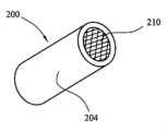
図1は本発明の第一の実施形態によるエアロゾル発生システムの概略図である。システムは装置100およびカートリッジ200を備える。装置はリチウムイオンリン酸型電池102および制御電子回路104を含むメインハウジング101を備える。メインハウジング101はまた、その中にカートリッジ200を受けるくぼみ112を画定する。装置はまた、出口124を含むマウスピース部分120も含む。マウスピース部分は、この例ではヒンジによる接続でメインハウジング101に接続されているが、スナップ式装着またはねじ式取付など、任意の種類の接続を使用しうる。空気吸込み口122は図1に示す通り、マウスピース部分が閉位置内にある時にマウスピース部分120と本体101との間に画定される。1 is a schematic diagram of an aerosol generation system according to a first embodiment of the present invention. The system includes a
マウスピース部分の内部にはフラットスパイラルインダクタコイル110がある。コイル110は銅板からスパイラルコイルをスタンピングまたは切断することにより形成される。コイル110は図3で明瞭に図示されている。コイル110は入口122を通り出口124に引き出される空気がコイルを通過するように、空気吸込み口122と空気出口124の間に位置する。コイルは腐食抵抗性のある被覆またはエンクロージャによって覆われうる。Inside the mouthpiece portion is a flat
カートリッジ200は、毛細管材料を保持し、液体エアロゾル形成基体で充填されたカートリッジハウジング204を備える。カートリッジハウジング204は流体不浸透性であるが、浸透性のサセプタ素子210により覆われた開放端を持つ。カートリッジ200は図2で明瞭に図示されている。この実施形態ではサセプタ素子はフェライトメッシュである。エアロゾル形成基体はメッシュの間隙内にメニスカスを形成できる。サセプタ用の別の選択肢は、オープンメッシュ構造を持つグラファイト繊維である。The
カートリッジ200が装置と係合し、くぼみ112内に受けられた時、サセプタ素子210はフラットスパイラルコイル110に隣接して位置する。カートリッジ200は装置内に逆さまに挿入できないことを確保するためにキー付きの特徴を含みうる。When the
使用時に、ユーザーはマウスピース部分120で吸入して、空気を空気吸込み口122を通してマウスピース部分120に引き出し、出口124からユーザーの口に出す。装置は制御電子回路104の部品としてマイクロフォンの形態の吸入センサー106を含む。ユーザーがマウスピース部分で吸入すると、小さな空気の流れがセンサー入口121を通り、マイクロフォン106を通過し、マウスピース部分120にまで引き出される。吸入が検出されると、制御電子回路は高周波振動電流をコイル110に供給する。これにより、図1で点線で示す通り、振動する磁場が生成される。また、LED 108が作動し、装置が起動されたことを示す。振動する磁場はサセプタ素子を通過し、サセプタ素子内に渦電流を誘起する。サセプタ素子はジュール加熱の結果として加熱され、そのサセプタ素子に近いエアロゾル形成基体を気化するのに十分な温度に達する。すでに述べたように、ヒステリシス損失もサセプタ素子の有意な加熱を生成しうる。気化されたエアロゾル形成基体は空気吸込み口から空気出口への空気の流れに混入され、ユーザーの口に入る前に冷めてマウスピース部分の内部でエアロゾルを形成する。制御電子回路は、吸入が検出されると、振動する電流をコイルに所定の持続期間(この例では5秒間)にわたり供給し、その後、新しい吸入が検出されるまで電流がオフになる。In use, the user inhales into the
カートリッジが単純でかつ堅牢なデザインを持ち、市場で入手可能なカートマイザーと比較して安価に製造できることが分かる。この実施形態で、カートリッジは円形の円柱形状を持ち、サセプタ素子はカートリッジハウジングの円形の開放端を補う。ただし、その他の構成も可能である。図4はサセプタ素子がカートリッジハウジング204内の長方形の開口部を補う鋼製メッシュ220の細片である、代替的なカートリッジ設計の端面図である。図5は別の代替的なサセプタ素子の端面図である。図5では、サセプタは半径方向バーによって結合された3つの同心円である。サセプタ素子はカートリッジハウジング内の円形開口部にかかる。It can be seen that the cartridge has a simple and robust design and is inexpensive to manufacture compared to commercially available cartomizers. In this embodiment, the cartridge has a circular cylindrical shape and the susceptor element spans a circular open end of the cartridge housing. However, other configurations are possible. FIG. 4 is an end view of an alternative cartridge design in which the susceptor element is a strip of
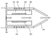
図6は第二の実施形態を図示したものである。図6ではシステムの前部端のみが、吸入検出メカニズムを含めて図1に示すものと同一の電池および制御電子回路を使用できるものとして表示されている。図6ではフラットスパイラルコイル136が装置の本体101内のマウスピース部分120に対するくぼみの反対側の端部に位置するが、システムは本質的に同一の方法で動作する。スペーサー134はコイル136とサセプタ素子210との間に気流スペースがあることを確保する。気化されたエアロゾル形成基体はサセプタを通過する入口132から出口124への空気の流れ内に混入される。図6に示す実施形態では、一部の空気はサセプタ素子を通過することなく、入口132から出口124に直接流れることができる。この直接的な空気の流れはマウスピース部分で蒸気と混合され、冷却の速度が増し、エアロゾル内の最適な水滴サイズが確保される。Figure 6 illustrates a second embodiment. In Figure 6, only the front end of the system is shown, which can use the same battery and control electronics as shown in Figure 1, including the inhalation detection mechanism. In Figure 6, the
図6に示す実施形態では、カートリッジは図1のカートリッジと同一のサイズおよび形状であり、同一のハウジングおよびサセプタ素子を持つ。ところが、図6のカートリッジ内の毛細管材料は図1のそれとは異なる。図6のカートリッジ内には別個の2つの毛細管材料202、206がある。第一の毛細管材料206のディスクが、使用中のサセプタ素子210と接触するために提供されている。第二の毛細管材料202の大きい方の本体はサセプタ素子への第一の毛細管材料206の反対側に提供されている。第一の毛細管材料および第二の毛細管材料はどちらも、液体エアロゾル形成基体を保持する。サセプタ素子と接触する第一の毛細管材料206は第二の毛細管材料202より高い熱分解温度(少なくとも160℃以上、例えば約250℃など)を持つ。第一の毛細管材料206は第二の毛細管材料がその熱分解温度を上回る温度に晒されないように、使用時に非常に高温になるサセプタ素子を第二の毛細管材料202から分離するスペーサーとしての役目を効果的に果たす。第一の毛細管材料全体での熱勾配は第二の毛細管材料がその熱分解温度を下回る温度に晒されるようにするためである。第二の毛細管材料202は第一の毛細管材料206への優れた芯の性能を持つものを選択でき、単位体積あたり第一の毛細管材料よりも多くの液体を保持でき、また第一の毛細管材料よりも安価なものとしうる。この例では第一の毛細管材料はガラス繊維またはガラス繊維を含む素子などの耐熱素子であり、また第二の毛細管材料は高密度ポリエチレン密度ポリエチレン(HDPE)、またはポリエチレンテレフタレート(PET)などのポリマーである。In the embodiment shown in FIG. 6, the cartridge is the same size and shape as the cartridge of FIG. 1, and has the same housing and susceptor element. However, the capillary material in the cartridge of FIG. 6 is different from that of FIG. 1. There are two separate
図7は第三の実施形態を図示したものである。図7ではシステムの前部端のみが、吸入検出メカニズムを含めて図1に示すものと同一の電池および制御電子回路を使用できるものとして表示されている。図7ではカートリッジ240は立方体であり、カートリッジの反対側面にあるサセプタ素子242の2つの細片で形成されている。カートリッジは図8に単独で示す。装置は、カートリッジがくぼみ内に受けられている時に、サセプタ素子細片242がコイル142に隣接するように、くぼみの反対側に位置する2つのフラットスパイラルコイル142を備える。コイル142は図9に示す通り、サセプタ細片の形状に対応するように長方形である。渦電流のより高い密度を許容し、外皮への影響を最小化するので、長方形の形状は有利である。気流通路は、ユーザーがマウスピース部分120で吸入した時に、入口144からの空気がサセプタ細片を通過し出口124に向かうように、コイル142とサセプタ細片242の間に提供されている。Figure 7 illustrates a third embodiment. Only the front end of the system is shown in Figure 7 as it can use the same battery and control electronics as shown in Figure 1, including the inhalation detection mechanism. In Figure 7, the
図1の実施形態に示す通り、カートリッジは毛細管材料および液体エアロゾル形成基体を含む。毛細管材料は液体基体をサセプタ素子細片242に運ぶように配列されている。As shown in the embodiment of FIG. 1, the cartridge includes a capillary material and a liquid aerosol-forming substrate. The capillary material is arranged to convey the liquid substrate to the susceptor element strips 242.
図10は第四の実施形態を図示したものである。図10ではシステムの前部端のみが、吸入検出メカニズムを含めて図1に示すものと同一の電池および制御電子回路を使用できるものとして表示されている。図10の装置は、図6に示した装置と類似した構造を持ち、装置の本体101内でくぼみのマウスピース部分120と反対側の端部において配置されたフラットスパイラルインダクタコイル152を備える。しかし、図10に示すカートリッジは図6に示したものとは異なる構造を持つ。図10のカートリッジは、図11に端面図で示される。カートリッジハウジング250は円筒形状を持つが、これを通過する中央通路256を持つ。エアロゾル形成基体は中央通路を囲む環状スペース内に保持され、前述のものと同様に、ハウジング250の中の毛細管材料内に保持されうる。毛細管芯がカートリッジの一方の端において中央通路256にわたって提供される。毛細管芯はフェライト繊維で形成され、エアロゾル形成基体のための芯とコイル152によって誘導加熱されるサセプタとしてとの両方の役目を果たす。10 illustrates a fourth embodiment. Only the front end of the system is shown in FIG. 10 as it may use the same battery and control electronics as shown in FIG. 1, including the inhalation detection mechanism. The device of FIG. 10 has a similar structure to the device shown in FIG. 6, with a flat
使用時には、エアロゾル形成基体はフェライトの芯252の中へと引き出される。吸入が検出された時に、コイル152が起動され、振動磁界が発生する。芯を横切って変化する磁束は芯の中の渦電流およびヒステリシス損失を誘起し、芯を加熱し、芯の中のエアロゾル形成基体を気化する。気化したエアロゾル形成基体は、マウスピース部分のユーザーの吸入によって空気吸込み口154から出口124へとシステムを通して引き出される空気中に混入される。空気はエアロゾル形成チャンバの役目を果たす内部通路256を通して流れ、出口124へと移動しながら空気と蒸気を冷却する。カートリッジによって画定された中空スペース内で蒸気が冷めるので、中空カートリッジの使用はシステムに対してより短い全長を許容する。In use, the aerosol-forming substrate is drawn into the
図12は第五の実施形態を図示したものである。図12ではシステムの前部端のみが、吸入検出メカニズムを含めて図1に示すものと同一の電池および制御電子回路を使用できるものとして表示されている。図12の装置は図7の装置と類似した構造を持ち、フラットスパイラルコイルはカートリッジが受けられるくぼみを囲むハウジングの側壁に位置し、かつハウジングの形状と一致する形状となっている。ただし、カートリッジは異なる構造を持つ。図12のカートリッジ260は図10に示すカートリッジのそれと類似した中空の円筒形状を持つ。カートリッジは毛細管材料を含み、液体エアロゾル形成基体で充填される。カートリッジ260の内部表面、すなわち、内部通路166を囲む表面は流体浸透性のサセプタ素子、この例ではフェライトメッシュを備える。フェライトメッシュはカートリッジの内部表面全体を、またはカートリッジの内部表面の一部分のみを裏打ちしうる。12 illustrates a fifth embodiment. Only the front end of the system is shown in FIG. 12 as it may use the same battery and control electronics as shown in FIG. 1, including the inhalation detection mechanism. The device of FIG. 12 has a similar structure to the device of FIG. 7, with a flat spiral coil located on the side wall of the housing surrounding the cavity in which the cartridge is received and shaped to match the shape of the housing. However, the cartridge has a different structure.
使用時に、ユーザーはマウスピース部分120で吸入して、空気を空気吸込み口164からカートリッジの中央通路に通し、サセプタ素子262を通過させマウスピース部分120に引き出し、出口124からユーザーの口に出す。吸入が検出されると、制御電子回路は高周波振動電流をコイル162に供給する。これが振動する磁場を発生させる。振動する磁場はサセプタ素子を通過し、サセプタ素子内に渦電流およびヒステリシス損失を誘起する。サセプタ素子は加熱され、そのサセプタ素子に近いエアロゾル形成基体を気化するのに十分な温度に達する。気化されたエアロゾル形成基体はサセプタ素子を通過し、空気吸込み口から空気出口への空気の流れに混入され、ユーザーの口に入る前に冷めて通路およびマウスピース部分の内部でエアロゾルを形成する。In use, the user inhales into the
図13は第六の実施形態を図示したものである。図13ではシステムの前部端のみが、吸入検出メカニズムを含めて図1に示すものと同一の電池および制御電子回路を使用できるものとして表示されている。図13に示すカートリッジ270は図12に示すものと同一である。ただし、図13の装置はカートリッジの中央通路内に延びてサセプタ素子272の近くに振動する磁場を発生させる保持用ブレード176上のフラットスパイラルインダクタコイル172を含むという、異なる構成を持つ。A sixth embodiment is illustrated in FIG. 13, where only the front end of the system is shown as it can use the same battery and control electronics as shown in FIG. 1, including the inhalation detection mechanism. The
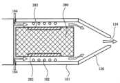
図14は第七の実施形態を図示したものである。図14ではシステムの前部端のみが、吸入検出メカニズムを含めて図1に示すものと同一の電池および制御電子回路を使用できるものとして表示されている。図14では、装置は図12に示すものと類似した構造を持つ。ただし図14のカートリッジは、エアロゾル形成基体で浸されたサセプタ素子280で充填されている。カートリッジのハウジングは、気化したエアロゾル形成基体がカートリッジから漏れ出るのを許容する蒸気浸透性膜282を含む。蒸気浸透性膜282は、空気吸込み口184から空気出口124へ延びる気流チャネルに隣接して配置される。14 illustrates a seventh embodiment. Only the front end of the system is shown in FIG. 14, which may use the same battery and control electronics as shown in FIG. 1, including the inhalation detection mechanism. In FIG. 14, the device has a similar structure to that shown in FIG. 12, except that the cartridge in FIG. 14 is filled with
使用時に、ユーザーはマウスピース部分120で吸入して、空気を空気吸込み口184を通してカートリッジ282の蒸気浸透性部分を通過して、マウスピース部分120へと引き出し、出口124からユーザーの口に出す。吸入が検出されると、制御電子回路は高周波振動電流をコイル182に提供する。これが振動する磁場を発生させる。振動する磁場はカートリッジ内のサセプタ素子を通過し、サセプタ素子内に渦電流およびヒステリシス損失を誘起する。サセプタ素子は加熱され、エアロゾル形成基体を気化するのに十分な温度に達する。気化されたエアロゾル形成基体は空気吸込み口から空気出口への空気の流れによってカートリッジ282の蒸気浸透性膜を通して引き出され、ユーザーの口に入る前に冷めてマウスピース部分の内部でエアロゾルを形成する。In use, the user inhales into the
図1、2、4、5、6、7、8、10、11、12、および13に示すカートリッジを図12および13に示すような中空カートリッジの中に同一の方法で充填するためにサセプタ素子を使用して、空気が空気吸込み口から空気出口へと流れるとこれを通過するように、カートリッジハウジングの蒸気浸透性部分を一部分の中に提供することは当然ながら可能である。It is of course possible to use a susceptor element to fill the cartridges shown in Figures 1, 2, 4, 5, 6, 7, 8, 10, 11, 12, and 13 in the same manner into a hollow cartridge as shown in Figures 12 and 13, providing a vapor-permeable portion of the cartridge housing in one portion through which air flows from the air inlet to the air outlet.
図15は第八の実施形態を図示したものである。図15ではシステムの前部端のみが、吸入検出メカニズムを含めて図1に示すものと同一の電池および制御電子回路を使用できるものとして表示されている。図15の実施形態では、カートリッジを非常に小さくし、一回の使用(例えば一回の喫煙セッション、または薬剤の一回の投与)のためにちょうど十分なだけエアロゾル形成基体を保持する。カートリッジは、フェライト材料でできており、エアロゾル形成基体290を保持する、サセプタフォイルハウジング292を含む。カートリッジのハウジングの前部端294は、蒸気浸透性となるように穿孔されている。カートリッジはフラットスパイラルインダクタコイル192に隣接して装置内のくぼみに係合されている。15 illustrates an eighth embodiment. Only the front end of the system is shown in FIG. 15, which may use the same battery and control electronics as shown in FIG. 1, including the inhale detection mechanism. In the embodiment of FIG. 15, the cartridge is very small and holds just enough aerosol-forming substrate for a single use (e.g., a single smoking session, or a single dose of medication). The cartridge includes a
使用時に、ユーザーはマウスピース部分120で吸入して、空気を空気吸込み口194からカートリッジ294の蒸気浸透性部分を通過してマウスピース部分120へと引き出し、出口124からユーザーの口に出す。吸入が検出されると、制御電子回路は高周波振動電流をコイル192に提供する。これが振動する磁場を発生させる。振動する磁場はカートリッジハウジングのサセプタ素子を通過し、サセプタ素子内に渦電流およびヒステリシス損失を誘起する。サセプタ素子は加熱され、エアロゾル形成基体を気化するのに十分な温度に達する。気化されたエアロゾル形成基体は空気吸込み口から空気出口への空気の流れによってカートリッジ294の蒸気浸透性部分を通して引き出され、ユーザーの口に入る前に冷めてマウスピース部分の内部でエアロゾルを形成する。In use, the user inhales into the
説明したすべての実施形態は本質的に同一の電子回路104により駆動されうる。図16Aは、クラスE電力増幅器を使用してインダクタコイルに高周波振動電流を提供するために使用される回路の第一の例を図示したものである。図16Aから分かる通り、回路には、電界効果トランジスタ(FET)1110(例えば、金属酸化膜半導体電界効果トランジスタ(MOSFET))、切換信号(ゲート・ソース間電圧)をFET 1110に供給するための矢印1120で示したトランジスタスイッチ供給回路、および分路コンデンサーC1、およびコンデンサーC2とインダクタL2の直列接続を含むLC負荷ネットワーク1130を備えた、トランジスタスイッチ1100を含む、クラスE電力増幅器が含まれる。電池101を備えたDC電源はチョークL1を含み、DC供給電圧を供給する。図16Aには合計オーム負荷1140を表すオーム抵抗Rも示されており、これは記号L2の付いたフラットスパイラルインダクタコイルのオーム抵抗Rコイルと、サセプタ素子のオーム抵抗RLoadの和である。 All of the described embodiments can be driven by essentially the same
構成要素の数が非常に少ないため、電源回路の体積は極端に小さく保つことができる。この極端に小さい体積の電源回路はLC負荷ネットワーク1130のインダクタL2がサセプタ素子との誘導結合のためのインダクタとして直接的に使用されているために可能であり、またこの体積が小さいことから、誘導性の加熱装置の全体寸法が小さく保たれうる。The volume of the power supply circuit can be kept extremely small because the number of components is very small. This extremely small volume of the power supply circuit is possible because inductor L2 of the
クラスE電力増幅器の概略的な動作原理は公知であり、既に言及した記事「Class-E RF Power Amplifiers(クラスE RF電力増幅器)」(Nathan O.Sokal、American Radio Relay League(ARRL)(米国コネチカット州ニューイントン)の隔月誌QEX、2001年1月/2月号、9~20ページに公表)に詳細に説明されており、いくつかの概略的原理を以下に説明する。The general operating principles of class-E power amplifiers are known and described in detail in the already mentioned article "Class-E RF Power Amplifiers" (Nathan O. Sokal, published in the bimonthly magazine QEX, January/February 2001, pages 9-20, American Radio Relay League (ARRL), Newington, Connecticut, USA), and some general principles are described below.
トランジスタスイッチ供給回路1120は長方形のプロフィールを持つ切換電圧(FETのゲート・ソース間電圧)をFET 1110に対して供給すると仮定する。FET 1321が導通している限り(「オン」状態)、基本的に短絡(低抵抗)を構成し、電流全体がチョークL1およびFET 1110を通過して流れる。FET 1110が非導通の時(「オフ」状態)、FET 1110は基本的に開回路(高抵抗)を表すため、電流全体がLC負荷ネットワークに流れ込む。これら2つの状態間でのトランジスタの切換は供給されるDC電圧およびDC電流をAC電圧およびAC電流に転換させる。Assume that transistor switch supply circuit 1120 supplies a switching voltage (the gate-to-source voltage of the FET) with a rectangular profile to
サセプタ素子を効率的に加熱するために、供給されたDC電力のできるだけ多くがAC電力の形態でインダクタL2に転送され、その後でインダクタL2に誘導結合されたサセプタ素子に転送される。上記でさらに詳しく説明した通り、サセプタ素子(渦電流損失、ヒステリシス損失)内で分散される電力がサセプタ素子内で熱を発生する。言い換えれば、FET 1110での電力損失が最小化され、サセプタ素子での電力損失が最大化されなければならない。To efficiently heat the susceptor element, as much of the supplied DC power as possible is transferred in the form of AC power to inductor L2 and then to the susceptor element which is inductively coupled to inductor L2. As explained in more detail above, the power dissipated in the susceptor element (eddy current losses, hysteresis losses) generates heat in the susceptor element. In other words, the power loss in the
AC電圧/電流の一つの期間中のFET 1110での電力損失は、交流電圧/電流のその期間中の各時点でのトランジスタ電圧と電流の積をその期間全体について積分し、その期間全体について平均化したものである。その期間の一部ではFET 1110は高い電圧を持続しなければならず、またその期間の一部では高い電流を伝導しなければならないため、高い電圧と高い電流が同時に発生することは避けなければならない。これはFET 1110での著しい電力損失につながるためである。FET 1110の「オン」状態では、トランジスタ電圧はほぼゼロであり、高い電流がFETを通過して流れる。FET 1110の「オフ」状態では、トランジスタ電圧は高いが、FET 1110を通過する電流はほぼゼロである。The power dissipated in
また、不可避的な切換の移行は期間のいくらかの部分全体にわたる。それでもなお、FET 1110での高い電力損失を表す高い電圧・電流の積は、以下の追加的な手段によって回避できる。第一に、トランジスタを通過する電流がゼロに低下するまで、トランジスタ電圧の上昇を遅延する。第二に、トランジスタを通過する電流が増大し始める前に、トランジスタ電圧がゼロに戻る。これは分路コンデンサーC1およびコンデンサーC2とインダクタL2の直列接続を含む負荷ネットワーク1130によって達成されるが、この負荷ネットワークはFET 1110と負荷1140の間のネットワークである。第三に、ターンオン時のトランジスタ電圧は事実上ゼロである(バイポーラジャンクショントランジスタ「BJT」については、飽和オフセット電圧Vo)。ターンオントランジスタは充電された分流コンデンサーC1を放電せず、そのため分流コンデンサーの蓄積エネルギーの分散が回避される。第四に、ターンオン時のトランジスタ電圧の勾配はゼロである。次に、負荷ネットワークによってターンオントランジスタに注入される電流は制御された適度なレートでゼロから滑らかに増大し、その結果として電力損失が低くなり、その一方、トランジスタのコンダクタンスはターンオン移行時にゼロから高まる。その結果、トランジスタの電圧および電流が同時に高くなることは決してない。電圧および電流の切換の移行は相互に時間がずらされている。L1、C1およびC2の値はサセプタ素子内での電力の効率的な分散が最大となるように選択できる。 Also, the unavoidable switching transitions span some portion of the time period. Nevertheless, the high voltage-current products, which represent high power losses in the
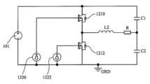
本開示によるほとんどのシステムでクラスE電力増幅器が好ましいが、その他の回路構造を使用することも可能である。図16BはクラスD電力増幅器を使用してインダクタコイルに高周波振動電流を供給するために使用される回路の第二の例を図示したものである。図16Bの回路は2つのトランジスタ1210、1212に接続された電池101を備える。2つのトランジスタ1210、1212のオン・オフを切り換えるための2つの切換要素1220、1222が提供されている。スイッチは、2つのトランジスタのうちもう一方がオンになっている時に、2つのトランジスタ1210、1212のうちの一方が確実にオフになるような方法で高周波で制御される。フラットスパイラルインダクタコイルはここでもL2で表示され、コイルとサセプタ素子の合計オーム抵抗はRで表示され、C1およびC2の値はサセプタ素子内での電力の効率的な分散が最大となるように選択できる。While a class E power amplifier is preferred in most systems according to the present disclosure, other circuit configurations may be used. FIG. 16B illustrates a second example of a circuit used to provide a high frequency oscillating current to an inductor coil using a class D power amplifier. The circuit of FIG. 16B includes a
サセプタ素子はサセプタ素子が加熱されるべき望ましい温度に近いキュリー温度を持つ材料または材料の組み合わせで製造できる。サセプタ素子の温度がこのキュリー温度を超えると、材料は強磁性から常磁性に変化する。従って、常磁性を持つ材料のヒステリシス損失は強磁性を持つ材料のそれよりもずっと低いため、サセプタ素子内のエネルギー分散は著しく低減される。サセプタ素子内でのこの電力損失の低減は検出可能であり、またそのため、例えば、DC/ACインバータによるAC電力の発生は、サセプタ素子がキュリー温度を再び下回るまで冷却され、再び強磁性となるまで中断されうる。その後で、DC/ACインバータによるAC電力の発生が再開されうる。The susceptor element can be made of a material or combination of materials that has a Curie temperature close to the desired temperature to which the susceptor element should be heated. When the temperature of the susceptor element exceeds this Curie temperature, the material changes from ferromagnetic to paramagnetic. Thus, the energy dissipation in the susceptor element is significantly reduced, since the hysteresis losses of paramagnetic materials are much lower than those of ferromagnetic materials. This reduction in power dissipation in the susceptor element is detectable, and so, for example, the generation of AC power by a DC/AC inverter can be interrupted until the susceptor element has cooled below the Curie temperature again and is ferromagnetic again. The generation of AC power by the DC/AC inverter can then be resumed.
当該技術分野において通常の技量を持つ者であれば、本開示によるサセプタ素子を組み込んだその他のカートリッジ設計を思い付くことができる。例えば、カートリッジはマウスピース部分を含んでもよく、望ましい任意の形状を持つものでよい。その上、本開示によるコイルおよびサセプタの配列は既に説明したその他のタイプのシステムで使用することができ、これには加湿器、エアフレッシュナー、およびその他のエアロゾル発生システムなどがある。A person of ordinary skill in the art can conceive of other cartridge designs incorporating susceptor elements according to the present disclosure. For example, the cartridge may include a mouthpiece portion and may have any desired shape. Moreover, coil and susceptor arrangements according to the present disclosure may be used in other types of systems already described, including humidifiers, air fresheners, and other aerosol generating systems.
上述の例示的な実施形態は例証するが限定はしない。上記で考察した例示的な実施形態に照らすことにより、上記の例示的な実施形態と一貫したその他の実施形態は今や当業者には明らかとなろう。The above exemplary embodiments are illustrative and not limiting. In light of the exemplary embodiments discussed above, other embodiments consistent with the above exemplary embodiments will now be apparent to those of skill in the art.
1. エアロゾル発生装置と、前記装置で使用されるように構成されたカートリッジと、を備える電気加熱式エアロゾル発生システムであって、前記装置が、
装置ハウジングと、
フラットスパイラルインダクタコイルと、
前記フラットスパイラルインダクタコイルに接続され、かつ高周波振動電流を前記フラットスパイラルインダクタコイルに提供するように構成された電源と、を備え、
前記カートリッジが、
エアロゾル形成基体を含み、かつ前記装置ハウジングを係合するように構成されたカートリッジハウジングと
前記エアロゾル形成基体を加熱するように位置するサセプタ素子と、を備える、電気加熱式エアロゾル発生システム。
2. 装置ハウジングが少なくとも前記カートリッジの一部分を受けるためのくぼみを備え、前記くぼみが内部表面を有する、1に記載の電気加熱式エアロゾル発生システム。
3. 前記フラットスパイラルインダクタコイルが前記電源に最も近いくぼみの表面の上またはこれに隣接して位置する、2に記載の電気加熱式エアロゾル発生システム。
4. 装置ハウジングが、本体およびマウスピース部分を備え、前記くぼみが前記本体内にあり、前記マウスピース部分が出口を有し、この出口を通して前記システムによって生成されたエアロゾルをユーザーの口の中へと引き出すことができ、前記フラットスパイラルインダクタコイルが前記マウスピース部分の中にある、2に記載の電気加熱式エアロゾル発生システム。
5. 前記装置が空気吸込み口から空気出口までの空気経路を備え、前記空気経路が前記フラットスパイラルインダクタを通過する、1~4のいずれかに記載の電気加熱式エアロゾル発生システム。
6. 複数のインダクタコイルを備える、1~5のいずれかに記載の電気加熱式エアロゾル発生システム。
7. 前記サセプタ素子が前記エアロゾル形成基体と接触する、1~6のいずれかに記載の電気加熱式エアロゾル発生システム。
8. 前記カートリッジハウジングが前記装置ハウジングと係合される時、前記サセプタ素子が、前記フラットスパイラルインダクタコイルに隣接して位置するように構成された前記カートリッジハウジングの壁の上に提供される、1~7のいずれかに記載の電気加熱式エアロゾル発生システム。
9. 前記カートリッジハウジングが前記装置ハウジングと係合される時、前記フラットスパイラルインダクタコイルと前記サセプタ素子との間に気流通路が提供される、1~8のいずれかに記載の電気加熱式エアロゾル発生システム。
10. 前記サセプタ素子が流体浸透性である、1~9のいずれかに記載の電気加熱式エアロゾル発生システム。
11. 前記サセプタ素子がシートの形態であり、かつ前記カートリッジハウジング内の開口全体に延びる、1~10のいずれかに記載の電気加熱式エアロゾル発生システム。
12. 前記システムが手持ち式喫煙システムである、1~11のいずれかに記載の電気加熱式エアロゾル発生システム。
13. 電気加熱式エアロゾル発生装置であって、
装置ハウジングと、
前記装置ハウジング内のフラットスパイラルインダクタコイルと
前記フラットスパイラルインダクタコイルに接続された電源と、を備え、かつ高周波振動電流を前記フラットスパイラルインダクタコイルに提供するように構成された、電気加熱式エアロゾル発生装置。
14. 前記装置ハウジングが、カートリッジの少なくとも一部分を受けるためのくぼみを画定し、前記カートリッジがエアロゾル形成基体および前記エアロゾル形成基体と接触するサセプタ素子を含むハウジングを備える、13に記載の電気加熱式エアロゾル発生装置。
15. エアロゾルを発生する方法であって、
サセプタと、前記サセプタに接触または前記サセプタに近接するエアロゾル形成基体と、を備えるカートリッジを提供することと、
前記サセプタがフラットスパイラルインダクタコイルに近接するように前記カートリッジを配置することと、
前記フラットスパイラル誘導コイルを通して高周波振動電流を通過させ、前記サセプタ内に電流を誘起し、これによって前記エアロゾル形成基体を加熱することと、を含む方法。1. An electrically heated aerosol generating system comprising an aerosol generating device and a cartridge configured for use with said device, said device comprising:
An apparatus housing;
A flat spiral inductor coil;
a power source connected to the flat spiral inductor coil and configured to provide a high frequency oscillating current to the flat spiral inductor coil;
The cartridge comprises:
An electrically heated aerosol generating system comprising: a cartridge housing containing an aerosol-forming substrate and configured to engage said device housing; and a susceptor element positioned to heat said aerosol-forming substrate.
2. The electrically heated aerosol generating system of claim 1, wherein the device housing comprises a recess for receiving at least a portion of the cartridge, the recess having an interior surface.
3. The electrically heated aerosol generating system of claim 2, wherein the flat spiral inductor coil is located on or adjacent to the surface of the cavity closest to the power source.
4. The electrically heated aerosol generating system of claim 2, wherein the device housing comprises a body and a mouthpiece portion, the cavity being within the body, the mouthpiece portion having an outlet through which aerosol generated by the system can be drawn into a user's mouth, and the flat spiral inductor coil being within the mouthpiece portion.
5. The electrically heated aerosol generating system according to any one of 1 to 4, wherein the device comprises an air path from an air inlet to an air outlet, the air path passing through the flat spiral inductor.
6. The electrically heated aerosol generating system according to any one of 1 to 5, comprising a plurality of inductor coils.
7. The electrically heated aerosol generating system according to any one of 1 to 6, wherein the susceptor element is in contact with the aerosol-forming substrate.
8. The electrically heated aerosol generation system according to any one of 1 to 7, wherein the susceptor element is provided on a wall of the cartridge housing configured to be positioned adjacent to the flat spiral inductor coil when the cartridge housing is engaged with the device housing.
9. The electrically heated aerosol generating system according to any one of 1 to 8, wherein an airflow passage is provided between the flat spiral inductor coil and the susceptor element when the cartridge housing is engaged with the device housing.
10. The electrically heated aerosol generating system according to any one of 1 to 9, wherein the susceptor element is fluid permeable.
11. The electrically heated aerosol generating system according to any one of 1 to 10, wherein the susceptor element is in the form of a sheet and extends across an opening in the cartridge housing.
12. The electrically heated aerosol generating system according to any one of 1 to 11, wherein the system is a handheld smoking system.
13. An electrically heated aerosol generating device, comprising:
An apparatus housing;
An electrically heated aerosol generator comprising: a flat spiral inductor coil within the device housing; and a power source connected to the flat spiral inductor coil, the power source configured to provide a high frequency oscillating current to the flat spiral inductor coil.
14. An electrically heated aerosol generating device according to claim 13, wherein the device housing defines a recess for receiving at least a portion of a cartridge, the cartridge comprising a housing containing an aerosol-forming substrate and a susceptor element in contact with the aerosol-forming substrate.
15. A method for generating an aerosol, comprising:
providing a cartridge comprising a susceptor and an aerosol-forming substrate in contact with or adjacent to the susceptor;
positioning the cartridge such that the susceptor is adjacent to a flat spiral inductor coil;
and passing a high frequency oscillating current through the flat spiral induction coil to induce a current in the susceptor, thereby heating the aerosol-forming substrate.
16. エアロゾル発生装置と、前記装置で使用されるように構成されたカートリッジと、を備える電気加熱式エアロゾル発生システムであって、前記装置が、
装置ハウジングと、
フラットスパイラルインダクタコイルと、
電源と、
前記フラットスパイラルインダクタコイルおよび前記電源に接続された電気回路と、
を備え、
前記電気回路が、クラスDまたはクラスEの電力増幅器を備えるDC/ACインバータを備え、かつ高周波振動電流を前記フラットスパイラルインダクタコイルに提供するように構成され、
前記カートリッジが、
エアロゾル形成基体を含み、かつ前記装置ハウジングを係合するように構成されたカートリッジハウジングと
前記エアロゾル形成基体を加熱するように位置するサセプタ素子と、を備え、
前記カートリッジハウジングが前記装置ハウジングと係合される時、前記フラットスパイラルインダクタコイルと前記サセプタ素子との間に気流通路が提供される、電気加熱式エアロゾル発生システム。
17. 装置ハウジングが少なくとも前記カートリッジの一部分を受けるためのくぼみを備え、前記くぼみが内部表面を有する、16に記載の電気加熱式エアロゾル発生システム。
18. 前記フラットスパイラルインダクタコイルが前記電源に最も近いくぼみの表面の上またはこれに隣接して位置する、17に記載の電気加熱式エアロゾル発生システム。
19. 装置ハウジングが、本体およびマウスピース部分を備え、前記くぼみが前記本体内にあり、前記マウスピース部分が出口を有し、この出口を通して前記システムによって生成されたエアロゾルをユーザーの口の中へと引き出すことができ、前記フラットスパイラルインダクタコイルが前記マウスピース部分の中にある、17に記載の電気加熱式エアロゾル発生システム。
20. 前記サセプタ素子と前記フラットスパイラルインダクタコイルとの間の最短距離は0.5~1mmである、16~19のいずれかに記載の電気加熱式エアロゾル発生システム。
21. 前記高周波振動電流は500kHz~30MHzの周波数を持ち、より好ましくは1~10MHzの周波数を持つ、16~20のいずれかに記載の電気加熱式エアロゾル発生システム。
22. 前記フラットスパイラルインダクタコイルは5mm~10mmの直径を有する、16~21のいずれかに記載の電気加熱式エアロゾル発生システム。
23. 前記装置が空気吸込み口から空気出口までの空気経路を備え、前記空気経路が前記フラットスパイラルインダクタコイルを通過する、16~22のいずれかに記載の電気加熱式エアロゾル発生システム。
24. 複数のインダクタコイルを備える、16~23のいずれかに記載の電気加熱式エアロゾル発生システム。
25. 前記サセプタ素子が前記エアロゾル形成基体と接触する、16~24のいずれかに記載の電気加熱式エアロゾル発生システム。
26. 前記カートリッジハウジング内の前記エアロゾル形成基体は液体である、16~25のいずれかに記載の電気加熱式エアロゾル発生システム。
27. 前記液体であるエアロゾル形成基体は毛細管材料内に保持される、26に記載の電気加熱式エアロゾル発生システム。
28. 前記毛細管材料は前記エアロゾル形成基体を前記サセプタ素子に運ぶように構成される、27に記載の電気加熱式エアロゾル発生システム。
29. 前記カートリッジハウジングが前記装置ハウジングと係合される時、前記サセプタ素子が、前記フラットスパイラルインダクタコイルに隣接して位置するように構成された前記カートリッジハウジングの壁の上に提供される、16~28のいずれかに記載の電気加熱式エアロゾル発生システム。
30. 前記サセプタ素子が流体浸透性である、16~29のいずれかに記載の電気加熱式エアロゾル発生システム。
31. 前記サセプタ素子がシートの形態であり、かつ前記カートリッジハウジング内の開口全体に延びる、16~30のいずれかに記載の電気加熱式エアロゾル発生システム。
32. 前記サセプタ素子が前記エアロゾル形成基体に埋め込まれている、16~30のいずれかに記載の電気加熱式エアロゾル発生システム。
33. 前記サセプタ素子が毛細管材料を含む、16~32のいずれかに記載の電気加熱式エアロゾル発生システム。
34. 前記サセプタ素子が前記システムを通る空気経路を横切って延びる毛細管芯を含む、33に記載の電気加熱式エアロゾル発生システム。
35. 前記システムが手持ち式喫煙システムである、16~34のいずれかに記載の電気加熱式エアロゾル発生システム。16. An electrically heated aerosol generating system comprising an aerosol generating device and a cartridge configured for use with said device, said device comprising:
An apparatus housing;
A flat spiral inductor coil;
Power supply,
an electrical circuit connected to the flat spiral inductor coil and the power source;
Equipped with
the electrical circuit comprises a DC/AC inverter comprising a class D or class E power amplifier and configured to provide a high frequency oscillating current to the flat spiral inductor coil;
The cartridge comprises:
a cartridge housing containing an aerosol-forming substrate and configured to engage the device housing; and a susceptor element positioned to heat the aerosol-forming substrate,
An electrically heated aerosol generating system, wherein an airflow passage is provided between the flat spiral inductor coil and the susceptor element when the cartridge housing is engaged with the device housing.
17. The electrically heated aerosol generating system of claim 16, wherein the device housing comprises a recess for receiving at least a portion of the cartridge, the recess having an interior surface.
18. The electrically heated aerosol generating system of claim 17, wherein the flat spiral inductor coil is located on or adjacent to a surface of the cavity closest to the power source.
19. The electrically heated aerosol generating system of claim 17, wherein the device housing comprises a body and a mouthpiece portion, the cavity being within the body, the mouthpiece portion having an outlet through which aerosol generated by the system can be drawn into a user's mouth, and the flat spiral inductor coil being within the mouthpiece portion.
20. The electrically heated aerosol generation system according to any one of 16 to 19, wherein the shortest distance between the susceptor element and the flat spiral inductor coil is 0.5 to 1 mm.
21. The electrically heated aerosol generating system according to any one of 16 to 20, wherein the high-frequency oscillating current has a frequency of 500 kHz to 30 MHz, more preferably 1 to 10 MHz.
22. The electrically heated aerosol generating system according to any one of 16 to 21, wherein the flat spiral inductor coil has a diameter of 5 mm to 10 mm.
23. The electrically heated aerosol generating system according to any one of 16 to 22, wherein the device comprises an air path from an air inlet to an air outlet, the air path passing through the flat spiral inductor coil.
24. The electrically heated aerosol generating system according to any one of 16 to 23, comprising a plurality of inductor coils.
25. The electrically heated aerosol generating system according to any one of 16 to 24, wherein the susceptor element is in contact with the aerosol-forming substrate.
26. The electrically heated aerosol generating system according to any one of 16 to 25, wherein the aerosol-forming substrate in the cartridge housing is a liquid.
27. The electrically heated aerosol generating system according to claim 26, wherein the liquid aerosol-forming substrate is held within a capillary material.
28. The electrically heated aerosol generating system of claim 27, wherein the capillary material is configured to convey the aerosol-forming substrate to the susceptor element.
29. The electrically heated aerosol generation system of any of 16 to 28, wherein the susceptor element is provided on a wall of the cartridge housing configured to be positioned adjacent to the flat spiral inductor coil when the cartridge housing is engaged with the device housing.
30. The electrically heated aerosol generating system according to any one of 16 to 29, wherein the susceptor element is fluid permeable.
31. The electrically heated aerosol generating system according to any one of 16 to 30, wherein the susceptor element is in the form of a sheet and extends across an opening in the cartridge housing.
32. The electrically heated aerosol generating system according to any one of 16 to 30, wherein the susceptor element is embedded in the aerosol-forming substrate.
33. The electrically heated aerosol generating system according to any one of 16 to 32, wherein the susceptor element comprises a capillary material.
34. The electrically heated aerosol generating system of 33, wherein the susceptor element includes a capillary wick extending across an air path through the system.
35. The electrically heated aerosol generating system according to any one of 16 to 34, wherein the system is a handheld smoking system.
Claims (13)
Translated fromJapanese装置ハウジングであって、前記装置ハウジングが前記カートリッジと係合した時に少なくとも前記カートリッジの一部分を受けるためのくぼみを備える、装置ハウジングと、
第一のフラットスパイラルインダクタコイルおよび第二のフラットスパイラルインダクタコイルであって、前記第一のフラットスパイラルインダクタコイルは前記第二のフラットスパイラルインダクタコイルに対して前記くぼみの反対側にある、第一のフラットスパイラルインダクタコイルおよび第二のフラットスパイラルインダクタコイルと、
前記第一のフラットスパイラルインダクタコイルおよび前記第二のフラットスパイラルインダクタコイルに接続された電源であって、高周波振動電流を前記第一のフラットスパイラルインダクタコイルおよび前記第二のフラットスパイラルインダクタコイルに提供するように構成された、電源と、
を備え、
前記カートリッジが、
エアロゾル形成基体を含み、かつ前記装置ハウジングを係合するように構成されたカートリッジハウジングと
前記エアロゾル形成基体を加熱するように位置するサセプタ素子と、
を備える、電気加熱式エアロゾル発生システム。 1. An electrically heated aerosol generating system comprising an aerosol generating device and a cartridge configured for use with said device, said device comprising:
a device housing including a recess for receiving at least a portion of the cartridge when the device housing is engaged with the cartridge;
a first flat spiral inductor coil and a second flat spiral inductor coil, the first flat spiral inductor coil being on an opposite side of the recess to the second flat spiral inductor coil;
a power supply connected to the first flat spiral inductor coil and the second flat spiral inductor coil, the power supply configured to provide a high frequency oscillating current to the first flat spiral inductor coil and the second flat spiral inductor coil;
Equipped with
The cartridge comprises:
a cartridge housing including an aerosol-forming substrate and configured to engage said device housing; a susceptor element positioned to heat said aerosol-forming substrate;
An electrically heated aerosol generating system comprising:
装置ハウジングであって、前記装置ハウジングがカートリッジと係合した時に少なくとも前記カートリッジの一部分を受けるためのくぼみを備え、前記カートリッジがエアロゾル形成基体および前記エアロゾル形成基体に接触するサセプタ素子を含むハウジングを備える、装置ハウジングと、
第一のフラットスパイラルインダクタコイルおよび第二のフラットスパイラルインダクタコイルであって、前記第一のフラットスパイラルインダクタコイルは前記第二のフラットスパイラルインダクタコイルに対して前記くぼみの反対側にある、第一のフラットスパイラルインダクタコイルおよび第二のフラットスパイラルインダクタコイルと、
前記第一のフラットスパイラルインダクタコイルおよび前記第二のフラットスパイラルインダクタコイルに接続された電源であって、高周波振動電流を前記第一のフラットスパイラルインダクタコイルおよび前記第二のフラットスパイラルインダクタコイルに提供するように構成された、電源と、
を備える、電気加熱式エアロゾル発生装置。 An electrically heated aerosol generating device, comprising:
an apparatus housing, the apparatus housing having a recess for receiving at least a portion of a cartridge when the apparatus housing is engaged with the cartridge, the cartridge comprising a housing containing an aerosol-forming substrate and a susceptor element in contact with the aerosol-forming substrate;
a first flat spiral inductor coil and a second flat spiral inductor coil, the first flat spiral inductor coil being on an opposite side of the recess to the second flat spiral inductor coil;
a power supply connected to the first flat spiral inductor coil and the second flat spiral inductor coil, the power supply configured to provide a high frequency oscillating current to the first flat spiral inductor coil and the second flat spiral inductor coil;
An electrically heated aerosol generating device comprising:
サセプタと、前記サセプタに接触または前記サセプタに近接するエアロゾル形成基体とを備えるカートリッジを提供することと、
前記カートリッジをエアロゾル発生装置ハウジングのくぼみの中で配置して、前記サセプタが、第一のフラットスパイラルインダクタコイルおよび前記第一のフラットスパイラルインダクタコイルに対して前記くぼみの反対側に配置された第二のフラットスパイラルインダクタコイルに近接するようにすることと、
前記第一のフラットスパイラルインダクタコイルおよび第二のフラットスパイラルインダクタコイルを通して高周波振動電流を通過させ、前記サセプタ内に電流を誘起し、これによって前記エアロゾル形成基体を加熱することと、
を含む方法。 1. A method for generating an aerosol, comprising:
providing a cartridge comprising a susceptor and an aerosol-forming substrate in contact with or adjacent to the susceptor;
placing the cartridge in a cavity of an aerosol generator housing such that the susceptor is adjacent to a first flat spiral inductor coil and a second flat spiral inductor coil disposed on an opposite side of the cavity from the first flat spiral inductor coil;
passing a high frequency oscillating current through the first flat spiral inductor coil and the second flat spiral inductor coil to induce a current in the susceptor, thereby heating the aerosol-forming substrate;
The method includes:
Priority Applications (1)
| Application Number | Priority Date | Filing Date | Title |
|---|---|---|---|
| JP2024140909AJP2024161052A (en) | 2014-05-21 | 2024-08-22 | Aerosol Generation System with Planar Induction Coil |
Applications Claiming Priority (6)
| Application Number | Priority Date | Filing Date | Title |
|---|---|---|---|
| EP14169224 | 2014-05-21 | ||
| EP14169224.4 | 2014-05-21 | ||
| EP14197252.1 | 2014-12-10 | ||
| EP14197252 | 2014-12-10 | ||
| JP2020034939AJP6965387B2 (en) | 2014-05-21 | 2020-03-02 | Aerosol generation system with planar induction coil |
| JP2021171429AJP7209069B2 (en) | 2014-05-21 | 2021-10-20 | Aerosol generation system with planar induction coil |
Related Parent Applications (1)
| Application Number | Title | Priority Date | Filing Date |
|---|---|---|---|
| JP2021171429ADivisionJP7209069B2 (en) | 2014-05-21 | 2021-10-20 | Aerosol generation system with planar induction coil |
Related Child Applications (1)
| Application Number | Title | Priority Date | Filing Date |
|---|---|---|---|
| JP2024140909ADivisionJP2024161052A (en) | 2014-05-21 | 2024-08-22 | Aerosol Generation System with Planar Induction Coil |
Publications (2)
| Publication Number | Publication Date |
|---|---|
| JP2023026667A JP2023026667A (en) | 2023-02-24 |
| JP7544877B2true JP7544877B2 (en) | 2024-09-03 |
Family
ID=53268779
Family Applications (5)
| Application Number | Title | Priority Date | Filing Date |
|---|---|---|---|
| JP2016567635AActiveJP6727134B2 (en) | 2014-05-21 | 2015-05-14 | Aerosol generation system with planar induction coil |
| JP2020034939AActiveJP6965387B2 (en) | 2014-05-21 | 2020-03-02 | Aerosol generation system with planar induction coil |
| JP2021171429AActiveJP7209069B2 (en) | 2014-05-21 | 2021-10-20 | Aerosol generation system with planar induction coil |
| JP2023001062AActiveJP7544877B2 (en) | 2014-05-21 | 2023-01-06 | Aerosol Generation System with Planar Induction Coil |
| JP2024140909APendingJP2024161052A (en) | 2014-05-21 | 2024-08-22 | Aerosol Generation System with Planar Induction Coil |
Family Applications Before (3)
| Application Number | Title | Priority Date | Filing Date |
|---|---|---|---|
| JP2016567635AActiveJP6727134B2 (en) | 2014-05-21 | 2015-05-14 | Aerosol generation system with planar induction coil |
| JP2020034939AActiveJP6965387B2 (en) | 2014-05-21 | 2020-03-02 | Aerosol generation system with planar induction coil |
| JP2021171429AActiveJP7209069B2 (en) | 2014-05-21 | 2021-10-20 | Aerosol generation system with planar induction coil |
Family Applications After (1)
| Application Number | Title | Priority Date | Filing Date |
|---|---|---|---|
| JP2024140909APendingJP2024161052A (en) | 2014-05-21 | 2024-08-22 | Aerosol Generation System with Planar Induction Coil |
Country Status (25)
| Country | Link |
|---|---|
| US (1) | US10028535B2 (en) |
| EP (1) | EP3145346B1 (en) |
| JP (5) | JP6727134B2 (en) |
| KR (3) | KR20240008414A (en) |
| CN (2) | CN112335938B (en) |
| AU (1) | AU2015263326B2 (en) |
| BR (1) | BR112016024989B1 (en) |
| CA (1) | CA2940096A1 (en) |
| DK (1) | DK3145346T3 (en) |
| ES (1) | ES2688374T3 (en) |
| IL (1) | IL246745B (en) |
| LT (1) | LT3145346T (en) |
| MX (1) | MX373743B (en) |
| MY (1) | MY183805A (en) |
| PH (1) | PH12016501363B1 (en) |
| PL (1) | PL3145346T3 (en) |
| PT (1) | PT3145346T (en) |
| RS (1) | RS57786B1 (en) |
| RU (1) | RU2680438C2 (en) |
| SG (1) | SG11201608818RA (en) |
| SI (1) | SI3145346T1 (en) |
| TW (1) | TWI661782B (en) |
| UA (1) | UA119348C2 (en) |
| WO (1) | WO2015177043A1 (en) |
| ZA (1) | ZA201604742B (en) |
Families Citing this family (186)
| Publication number | Priority date | Publication date | Assignee | Title |
|---|---|---|---|---|
| US20160345631A1 (en) | 2005-07-19 | 2016-12-01 | James Monsees | Portable devices for generating an inhalable vapor |
| US20140202476A1 (en) | 2011-09-06 | 2014-07-24 | British American Tobacco (Investments) Limited | Heating smokeable material |
| US10279934B2 (en) | 2013-03-15 | 2019-05-07 | Juul Labs, Inc. | Fillable vaporizer cartridge and method of filling |
| US10039321B2 (en) | 2013-11-12 | 2018-08-07 | Vmr Products Llc | Vaporizer |
| USD842536S1 (en) | 2016-07-28 | 2019-03-05 | Juul Labs, Inc. | Vaporizer cartridge |
| DE202014011260U1 (en) | 2013-12-23 | 2018-11-13 | Juul Labs Uk Holdco Limited | Systems for an evaporation device |
| US10159282B2 (en) | 2013-12-23 | 2018-12-25 | Juul Labs, Inc. | Cartridge for use with a vaporizer device |
| US20160366947A1 (en) | 2013-12-23 | 2016-12-22 | James Monsees | Vaporizer apparatus |
| USD825102S1 (en) | 2016-07-28 | 2018-08-07 | Juul Labs, Inc. | Vaporizer device with cartridge |
| US10076139B2 (en) | 2013-12-23 | 2018-09-18 | Juul Labs, Inc. | Vaporizer apparatus |
| US10058129B2 (en) | 2013-12-23 | 2018-08-28 | Juul Labs, Inc. | Vaporization device systems and methods |
| TWI660685B (en)* | 2014-05-21 | 2019-06-01 | 瑞士商菲利浦莫里斯製品股份有限公司 | Electrothermal aerosol generating system and cylinder used in the system |
| TWI661782B (en) | 2014-05-21 | 2019-06-11 | 瑞士商菲利浦莫里斯製品股份有限公司 | Electrically heated aerosol-generating system,electrically heated aerosol-generating deviceand method of generating an aerosol |
| HUE031205T2 (en)* | 2014-05-21 | 2017-07-28 | Philip Morris Products Sa | Aerosol generating article with multi-material susceptor |
| GB2527597B (en) | 2014-06-27 | 2016-11-23 | Relco Induction Dev Ltd | Electronic Vapour Inhalers |
| MX394125B (en) | 2014-12-05 | 2025-03-24 | Juul Labs Inc | CALIBRATED DOSE CONTROL |
| WO2016118901A1 (en)* | 2015-01-22 | 2016-07-28 | Texas Tech University System | System and method for non-contact interaction with mobile devices |
| WO2016198417A1 (en) | 2015-06-12 | 2016-12-15 | Philip Morris Products S.A. | Cartridge for aerosol-generating system |
| GB201511359D0 (en) | 2015-06-29 | 2015-08-12 | Nicoventures Holdings Ltd | Electronic vapour provision system |
| GB201511361D0 (en) | 2015-06-29 | 2015-08-12 | Nicoventures Holdings Ltd | Electronic vapour provision system |
| GB201511358D0 (en)* | 2015-06-29 | 2015-08-12 | Nicoventures Holdings Ltd | Electronic aerosol provision systems |
| GB201511349D0 (en) | 2015-06-29 | 2015-08-12 | Nicoventures Holdings Ltd | Electronic aerosol provision systems |
| US20170055574A1 (en) | 2015-08-31 | 2017-03-02 | British American Tobacco (Investments) Limited | Cartridge for use with apparatus for heating smokable material |
| US11924930B2 (en) | 2015-08-31 | 2024-03-05 | Nicoventures Trading Limited | Article for use with apparatus for heating smokable material |
| US20170055584A1 (en) | 2015-08-31 | 2017-03-02 | British American Tobacco (Investments) Limited | Article for use with apparatus for heating smokable material |
| GB2543329B (en)* | 2015-10-15 | 2018-06-06 | Jt Int Sa | A method for operating an electronic vapour inhaler |
| US10582726B2 (en) | 2015-10-21 | 2020-03-10 | Rai Strategic Holdings, Inc. | Induction charging for an aerosol delivery device |
| WO2017068096A1 (en)* | 2015-10-22 | 2017-04-27 | Philip Morris Products S.A. | Aerosol-generating system and capsule for use in an aerosol-generating system |
| US20170119049A1 (en)* | 2015-10-30 | 2017-05-04 | British American Tobacco (Investments) Limited | Article for Use with Apparatus for Heating Smokable Material |
| US20180317554A1 (en) | 2015-10-30 | 2018-11-08 | British American Tobacco (Investments) Limited | Article for use with apparatus for heating smokable material |
| US20170119050A1 (en) | 2015-10-30 | 2017-05-04 | British American Tobacco (Investments) Limited | Article for Use with Apparatus for Heating Smokable Material |
| US20170119046A1 (en) | 2015-10-30 | 2017-05-04 | British American Tobacco (Investments) Limited | Apparatus for Heating Smokable Material |
| US20170119051A1 (en) | 2015-10-30 | 2017-05-04 | British American Tobacco (Investments) Limited | Article for Use with Apparatus for Heating Smokable Material |
| US10820630B2 (en) | 2015-11-06 | 2020-11-03 | Rai Strategic Holdings, Inc. | Aerosol delivery device including a wirelessly-heated atomizer and related method |
| GB201522368D0 (en)* | 2015-12-18 | 2016-02-03 | Jt Int Sa | An aerosol generating device |
| CN108289509B (en)* | 2015-12-22 | 2021-11-26 | 菲利普莫里斯生产公司 | Cartridge for an aerosol-generating system and aerosol-generating system comprising a cartridge |
| EP3183980B1 (en) | 2015-12-22 | 2018-08-08 | Philip Morris Products S.a.s. | A cartridge for an aerosol-generating system and an aerosol-generating system comprising a cartridge |
| WO2017108991A1 (en) | 2015-12-22 | 2017-06-29 | Philip Morris Products S.A. | A cartridge for an aerosol-generating system and an aerosol-generating system comprising a cartridge |
| EP3183979B1 (en)* | 2015-12-22 | 2018-06-06 | Philip Morris Products S.a.s. | Cartridge for an aerosol-generating system and an aerosol-generating system comprising a cartridge |
| US10104912B2 (en)* | 2016-01-20 | 2018-10-23 | Rai Strategic Holdings, Inc. | Control for an induction-based aerosol delivery device |
| CO2018009342A2 (en) | 2016-02-11 | 2018-09-20 | Juul Labs Inc | Secure fixing cartridges for vaporizing devices |
| EP3413960B1 (en) | 2016-02-11 | 2021-03-31 | Juul Labs, Inc. | Fillable vaporizer cartridge and method of filling |
| US10405582B2 (en) | 2016-03-10 | 2019-09-10 | Pax Labs, Inc. | Vaporization device with lip sensing |
| MX2018011466A (en) | 2016-03-31 | 2019-01-10 | Philip Morris Products Sa | Airflow in aerosol generating system with mouthpiece. |
| US10104914B2 (en) | 2016-03-31 | 2018-10-23 | Altria Client Services Llc | Airflow in aerosol generating system with mouthpiece |
| GB201607839D0 (en) | 2016-05-05 | 2016-06-22 | Relco Induction Developments Ltd | Aerosol generating systems |
| USD849996S1 (en) | 2016-06-16 | 2019-05-28 | Pax Labs, Inc. | Vaporizer cartridge |
| SG11201810430WA (en)* | 2016-06-20 | 2019-01-30 | Philip Morris Products Sa | Heater assembly for an aerosol-generating system |
| USD851830S1 (en) | 2016-06-23 | 2019-06-18 | Pax Labs, Inc. | Combined vaporizer tamp and pick tool |
| USD836541S1 (en) | 2016-06-23 | 2018-12-25 | Pax Labs, Inc. | Charging device |
| AU2017289114B2 (en) | 2016-06-29 | 2020-04-30 | Nicoventures Trading Limited | Apparatus for heating smokable material |
| RU2020135859A (en)* | 2016-06-29 | 2020-12-04 | Никовенчерс Трейдинг Лимитед | DEVICE FOR HEATING SMOKING MATERIAL |
| US10791760B2 (en)* | 2016-07-29 | 2020-10-06 | Altria Client Services Llc | Aerosol-generating system including a cartridge containing a gel |
| CN109414056A (en) | 2016-07-29 | 2019-03-01 | 菲利普莫里斯生产公司 | Aerosol generating system including cartridge containing gel |
| CN109475189A (en)* | 2016-07-29 | 2019-03-15 | 菲利普莫里斯生产公司 | Aerosol generation system including heated gel container |
| CN207236078U (en)* | 2016-09-06 | 2018-04-17 | 深圳市合元科技有限公司 | Smoke generating device |
| CN206808660U (en) | 2016-10-31 | 2017-12-29 | 深圳市合元科技有限公司 | Electronic cigarette |
| US10524508B2 (en) | 2016-11-15 | 2020-01-07 | Rai Strategic Holdings, Inc. | Induction-based aerosol delivery device |
| RU2754659C2 (en)* | 2016-12-19 | 2021-09-06 | Филип Моррис Продактс С.А. | Aerosol generating system with cartridge and bypass air inlet |
| US11045615B2 (en) | 2016-12-19 | 2021-06-29 | Altria Client Services Llc | Vapor-generating systems |
| WO2018114441A1 (en) | 2016-12-19 | 2018-06-28 | Philip Morris Products S.A. | An aerosol-generating system comprising multiple aerosol-forming substrates and a piercing element |
| US10716333B2 (en) | 2016-12-19 | 2020-07-21 | Altria Client Services Llc | Aerosol-generating system having a cartridge and a bypass air inlet |
| CN110267556B (en) | 2017-02-24 | 2022-10-18 | 菲利普莫里斯生产公司 | Aerosol-generating system and cartridge for an aerosol-generating system having a two-part liquid storage compartment |
| HUE059840T2 (en) | 2017-02-24 | 2023-01-28 | Philip Morris Products Sa | Moulded mounting for an aerosol-generating element in an aerosol-generating system |
| US11696368B2 (en) | 2017-02-24 | 2023-07-04 | Altria Client Services Llc | Aerosol-generating system and a cartridge for an aerosol-generating system having a two-part liquid storage compartment |
| CA3047216A1 (en)* | 2017-02-28 | 2018-09-07 | Philip Morris Products S.A. | Aerosol-generating system with electrodes and sensors |
| GB201705206D0 (en) | 2017-03-31 | 2017-05-17 | British American Tobacco Investments Ltd | Apparatus for a resonance circuit |
| GB201705259D0 (en)* | 2017-03-31 | 2017-05-17 | British American Tobacco Investments Ltd | Induction coil arrangement |
| AR111392A1 (en)* | 2017-03-31 | 2019-07-10 | Philip Morris Products Sa | SUSCEPTING UNIT TO HEAT BY INDUCTION AN AEROSOL FORMER SUBSTRATE |
| GB201705208D0 (en)* | 2017-03-31 | 2017-05-17 | British American Tobacco Investments Ltd | Temperature determination |
| US11576424B2 (en) | 2017-04-05 | 2023-02-14 | Altria Client Services Llc | Susceptor for use with an inductively heated aerosol-generating device or system |
| KR20230169389A (en)* | 2017-04-05 | 2023-12-15 | 필립모리스 프로덕츠 에스.에이. | Susceptor for use with an inductively heated aerosol-generating device or system |
| GB2561867B (en)* | 2017-04-25 | 2021-04-07 | Nerudia Ltd | Aerosol delivery system |
| KR102821550B1 (en)* | 2017-05-10 | 2025-06-20 | 필립모리스 프로덕츠 에스.에이. | Aerosol-generating article, device and system for use with a plurality of aerosolforming substrates |
| GB201707805D0 (en) | 2017-05-16 | 2017-06-28 | Nicoventures Holdings Ltd | Atomiser for vapour provision device |
| DE102017111435B4 (en)* | 2017-05-24 | 2018-12-06 | Hauni Maschinenbau Gmbh | An evaporator unit for an inhaler and method for controlling an evaporator unit |
| US11785677B2 (en) | 2017-06-08 | 2023-10-10 | Altria Client Services Llc | Cartridge having a susceptor material |
| PL3634163T3 (en)* | 2017-06-08 | 2021-10-25 | Philip Morris Products S.A. | CARTRIDGE WITH SUSCEPTOR MATERIAL |
| US11053395B2 (en)* | 2017-06-12 | 2021-07-06 | Altria Client Services Llc | Corrosion-resistant reservoir for an e-vaping device and method of manufacturing thereof |
| US10792443B2 (en) | 2017-06-30 | 2020-10-06 | Blackship Technologies Development Llc | Composite micro-vaporizer wicks |
| CN119699679A (en)* | 2017-08-09 | 2025-03-28 | 菲利普莫里斯生产公司 | Aerosol generating device with inductor coils having reduced spacing |
| WO2019030360A1 (en) | 2017-08-09 | 2019-02-14 | Philip Morris Products S.A. | Aerosol-generating device with removable susceptor |
| HUE055702T2 (en) | 2017-08-09 | 2021-12-28 | Philip Morris Products Sa | Aerosol generation system with multiple induction coils |
| EP3664640B2 (en) | 2017-08-09 | 2025-02-19 | Philip Morris Products S.A. | Aerosol generating system with multiple susceptors |
| EP3664632B1 (en) | 2017-08-09 | 2024-09-04 | Philip Morris Products S.A. | Aerosol-generating device with susceptor layer |
| KR102562948B1 (en)* | 2017-08-09 | 2023-08-03 | 필립모리스 프로덕츠 에스.에이. | Aerosol generating device with flat inductor coil |
| JP6878684B2 (en)* | 2017-08-09 | 2021-06-02 | フィリップ・モーリス・プロダクツ・ソシエテ・アノニム | Aerosol generator with removable and insertable heating compartment |
| CN110944530B (en) | 2017-08-09 | 2023-09-29 | 菲利普莫里斯生产公司 | Aerosol generating system with non-circular inductor coil |
| KR102565586B1 (en)* | 2017-08-09 | 2023-08-10 | 필립모리스 프로덕츠 에스.에이. | Aerosol generating device with elastic susceptor |
| UA126925C2 (en)* | 2017-09-06 | 2023-02-22 | ДжейТі ІНТЕРНЕШНЛ СА | INDUCTION HEATING ASSEMBLY FOR STEAM GENERATING DEVICE |
| USD887632S1 (en) | 2017-09-14 | 2020-06-16 | Pax Labs, Inc. | Vaporizer cartridge |
| MY203861A (en) | 2017-09-15 | 2024-07-22 | Nicoventures Trading Ltd | Apparatus for heating smokable material |
| JP7254779B2 (en) | 2017-09-18 | 2023-04-10 | フィリップ・モーリス・プロダクツ・ソシエテ・アノニム | Cartridges for aerosol generation systems |
| US10517332B2 (en) | 2017-10-31 | 2019-12-31 | Rai Strategic Holdings, Inc. | Induction heated aerosol delivery device |
| WO2019105811A1 (en) | 2017-11-30 | 2019-06-06 | Philip Morris Products S.A. | Cartridge having an internal surface susceptor material |
| GB201721610D0 (en)* | 2017-12-21 | 2018-02-07 | British American Tobacco Investments Ltd | Circuitry for an induction element for an aerosol generating device |
| GB201721612D0 (en) | 2017-12-21 | 2018-02-07 | British American Tobacco Investments Ltd | Circuitry for a plurality of induction elements for an aerosol generating device |
| KR102551348B1 (en) | 2017-12-28 | 2023-07-05 | 제이티 인터내셔널 소시에떼 아노님 | Induction Heating Assemblies for Steam Generators |
| EP3732937B1 (en)* | 2017-12-28 | 2025-08-27 | JT International SA | Induction heating assembly for a vapour generating device |
| GB201722183D0 (en) | 2017-12-28 | 2018-02-14 | British American Tobacco Investments Ltd | Apparatus for heating aerosolisable material |
| PL3731668T3 (en)* | 2017-12-28 | 2023-08-28 | Jt International Sa | Induction heating unit for a steam generating device |
| TWI823887B (en)* | 2017-12-29 | 2023-12-01 | 瑞士商傑太日煙國際股份有限公司 | Induction heating assembly for a vapour generating device |
| US12201154B2 (en) | 2018-01-03 | 2025-01-21 | Cqens Technologies Inc. | Heat-not-burn device and method |
| US10750787B2 (en) | 2018-01-03 | 2020-08-25 | Cqens Technologies Inc. | Heat-not-burn device and method |
| US11272741B2 (en)* | 2018-01-03 | 2022-03-15 | Cqens Technologies Inc. | Heat-not-burn device and method |
| JP7225540B2 (en)* | 2018-01-31 | 2023-02-21 | 株式会社三洋物産 | game machine |
| JP7225538B2 (en)* | 2018-01-31 | 2023-02-21 | 株式会社三洋物産 | game machine |
| JP7225539B2 (en)* | 2018-01-31 | 2023-02-21 | 株式会社三洋物産 | game machine |
| JP7495349B2 (en)* | 2018-02-09 | 2024-06-04 | インペリアル、タバコ、リミテッド | Smoking substitute consumables |
| US11019850B2 (en) | 2018-02-26 | 2021-06-01 | Rai Strategic Holdings, Inc. | Heat conducting substrate for electrically heated aerosol delivery device |
| KR102488320B1 (en)* | 2018-04-27 | 2023-01-17 | 제이티 인터내셔널 소시에떼 아노님 | steam generating system |
| CN110403240B (en)* | 2018-04-28 | 2024-05-14 | 深圳御烟实业有限公司 | Aerosol-generating article |
| ES2926963T3 (en) | 2018-05-21 | 2022-10-31 | Jt Int Sa | Method and apparatus for manufacturing aerosol generating articles |
| WO2019237052A1 (en) | 2018-06-07 | 2019-12-12 | Juul Labs, Inc. | Cartridges for vaporizer devices |
| US11857717B2 (en) | 2018-06-29 | 2024-01-02 | Philip Morris Products S.A. | Aerosol generating system with enhanced aerosol delivery |
| US12011045B2 (en) | 2018-07-05 | 2024-06-18 | Philip Morris Products S.A. | Inductively heated aerosol-generating system with ambient temperature sensor |
| WO2020012233A1 (en)* | 2018-07-13 | 2020-01-16 | Akbar Rahmani Nejad | Hybrid electric machine |
| US10897925B2 (en) | 2018-07-27 | 2021-01-26 | Joseph Pandolfino | Articles and formulations for smoking products and vaporizers |
| US20200035118A1 (en) | 2018-07-27 | 2020-01-30 | Joseph Pandolfino | Methods and products to facilitate smokers switching to a tobacco heating product or e-cigarettes |
| CN119632302A (en) | 2018-07-31 | 2025-03-18 | 尤尔实验室有限公司 | Cartridge-based heat-without-burn vaporizer |
| KR102746101B1 (en)* | 2018-07-31 | 2024-12-24 | 필립모리스 프로덕츠 에스.에이. | Induction heatable cartridge for an aerosol generating system and an aerosol generating system comprising an induction heatable cartridge |
| WO2020035587A1 (en)* | 2018-08-17 | 2020-02-20 | Philip Morris Products S.A. | Aerosol-generating device for use with an aerosol-generating article comprising means for article identification |
| GB201814202D0 (en)* | 2018-08-31 | 2018-10-17 | Nicoventures Trading Ltd | A resonant circuit for an aerosol generating system |
| US11413409B2 (en) | 2018-09-12 | 2022-08-16 | Juul Labs, Inc. | Vaporizer including positive temperature coefficient of resistivity (PTCR) heating element |
| IL281655B2 (en) | 2018-09-25 | 2024-08-01 | Philip Morris Products Sa | Susceptor assembly for inductively heating an aerosol-forming substrate |
| EP3855955B1 (en)* | 2018-09-25 | 2022-09-07 | Philip Morris Products S.A. | Inductively heating aerosol-generating device comprising a susceptor assembly |
| WO2020064682A1 (en) | 2018-09-25 | 2020-04-02 | Philip Morris Products S.A. | Inductively heatable aerosol-generating article comprising an aerosol-forming substrate and a susceptor assembly |
| JP7508464B2 (en) | 2018-09-25 | 2024-07-01 | フィリップ・モーリス・プロダクツ・ソシエテ・アノニム | INDUCTION HEATING ASSEMBLY FOR INDUCTION HEATING AN AEROSOL-FORMING SUBSTRATE - Patent application |
| KR20210064307A (en) | 2018-09-25 | 2021-06-02 | 필립모리스 프로덕츠 에스.에이. | Method for inductive heating of heating assemblies and aerosol-forming substrates |
| JP2020069137A (en)* | 2018-10-31 | 2020-05-07 | 株式会社三洋物産 | Game machine |
| JP2020069140A (en)* | 2018-10-31 | 2020-05-07 | 株式会社三洋物産 | Game machine |
| JP2020069141A (en)* | 2018-10-31 | 2020-05-07 | 株式会社三洋物産 | Game machine |
| JP2020069143A (en)* | 2018-10-31 | 2020-05-07 | 株式会社三洋物産 | Game machine |
| EP3876763B1 (en) | 2018-11-05 | 2022-12-28 | Juul Labs, Inc. | A cartridge for a vaporizer device |
| CA3118713A1 (en)* | 2018-11-05 | 2020-05-14 | Juul Labs, Inc. | Cartridges for vaporizer devices |
| KR102278589B1 (en)* | 2018-12-06 | 2021-07-16 | 주식회사 케이티앤지 | Apparatus for generating aerosol using induction heating and method thereof |
| US20220015430A1 (en)* | 2018-12-10 | 2022-01-20 | Jt International S.A. | Aerosol Generating Device and System |
| KR102270185B1 (en)* | 2018-12-11 | 2021-06-28 | 주식회사 케이티앤지 | Apparatus for generating aerosol |
| WO2020146828A1 (en) | 2019-01-11 | 2020-07-16 | Juul Labs, Inc. | Vaporizer including positive temperature coefficient of resistivity heater |
| BR112021011385A2 (en)* | 2019-01-14 | 2021-08-31 | Philip Morris Products S.A. | RADIATION HEATED AEROSOL GENERATING SYSTEM, CARTRIDGE, AEROSOL GENERATING ELEMENT AND METHOD THEREOF |
| US20200237018A1 (en)* | 2019-01-29 | 2020-07-30 | Rai Strategic Holdings, Inc. | Susceptor arrangement for induction-heated aerosol delivery device |
| JP7311230B2 (en)* | 2019-03-11 | 2023-07-19 | ニコベンチャーズ トレーディング リミテッド | Aerosol delivery device |
| JP2020146312A (en)* | 2019-03-14 | 2020-09-17 | 株式会社三洋物産 | Game machine |
| JP2020146311A (en)* | 2019-03-14 | 2020-09-17 | 株式会社三洋物産 | Game machine |
| EP3965531A4 (en)* | 2019-04-29 | 2023-05-31 | Inno-It Co., Ltd. | Composite heating aerosol-generating device |
| JP7657738B2 (en)* | 2019-06-05 | 2025-04-07 | フィリップ・モーリス・プロダクツ・ソシエテ・アノニム | Aerosol generating device having a thermally conductive assembly |
| EP3982768A1 (en)* | 2019-06-13 | 2022-04-20 | JT International SA | An aerosol generating system, an aerosol generating device and an aerosol generating article |
| KR102281296B1 (en)* | 2019-06-17 | 2021-07-23 | 주식회사 케이티앤지 | Aerosol generating device and operation method thereof |
| GB201909338D0 (en)* | 2019-06-28 | 2019-08-14 | Nicoventures Trading Ltd | Inductor |
| GB201910509D0 (en) | 2019-07-23 | 2019-09-04 | Nicoventures Holdings Ltd | Porpus element for a vapour provision system |
| KR102255923B1 (en)* | 2019-08-09 | 2021-05-25 | 주식회사 케이티앤지 | Cleaning apparatus and aerosol generating system including the same |
| US20220378100A1 (en)* | 2019-10-31 | 2022-12-01 | Jt International Sa | An Aerosol-Generating Article in Form of a Disposable Shaped Cartridge Comprising a Foamed Aerosol-Generating Material |
| KR102323793B1 (en)* | 2019-11-21 | 2021-11-09 | 주식회사 이노아이티 | Induction heating device using fan coil |
| EP4042891B1 (en)* | 2019-11-26 | 2025-09-03 | China Tobacco Hunan Industrial Co., Ltd. | Ultrasonic atomizing sheet full-wave drive circuit, and ultrasonic electronic cigarette |
| CN120167696A (en)* | 2020-02-18 | 2025-06-20 | 尤尔实验室有限公司 | Evaporator device |
| KR102533744B1 (en)* | 2020-06-04 | 2023-05-18 | 주식회사 케이티앤지 | Airflow path structure and aerosol generating device comprising same |
| BR112022024616A2 (en) | 2020-06-05 | 2022-12-27 | Philip Morris Products Sa | SUSCEPTOR ASSEMBLY COMPRISING ONE OR MORE COMPOUND SUSCEPTOR PARTICLES |
| US20230210172A1 (en)* | 2020-06-10 | 2023-07-06 | Jt International Sa | A Cartridge for a Vapour Generating Device |
| US20230210179A1 (en)* | 2020-06-10 | 2023-07-06 | Jt International Sa | A Cartridge for a Vapour Generating Device |
| KR102593728B1 (en) | 2020-08-26 | 2023-10-24 | 주식회사 케이티앤지 | Aerosol-generating apparatus based on ultrasound and cartridge recognition method thereof |
| US20230354901A1 (en)* | 2020-09-23 | 2023-11-09 | Philip Morris Products S.A. | Aerosol-generating system with hybrid susceptor |
| WO2022063863A1 (en)* | 2020-09-23 | 2022-03-31 | Philip Morris Products S.A. | Aerosol-generating system with shaped susceptor |
| US20230354902A1 (en)* | 2020-09-23 | 2023-11-09 | Philip Morris Products S.A. | Stacked susceptor structure |
| WO2022063797A1 (en)* | 2020-09-23 | 2022-03-31 | Philip Morris Products S.A. | An inductively heated aerosol-generating system providing efficient and consistent heating of a planar susceptor element |
| KR102640828B1 (en)* | 2020-10-23 | 2024-02-23 | 주식회사 케이티앤지 | Induction heating type aerosol-generating article and apparatus |
| US20230389611A1 (en)* | 2020-10-29 | 2023-12-07 | Jt International Sa | A Cartridge for an Aerosol Generating Device, an Aerosol Generating Device and an Aerosol Generating System |
| CN112425820B (en)* | 2020-11-20 | 2025-08-22 | 上海烟草集团有限责任公司 | Electromagnetic heating device and aerosol generating device |
| CN214431831U (en)* | 2020-12-08 | 2021-10-22 | 深圳市合元科技有限公司 | Aerosol generator |
| KR102623331B1 (en)* | 2021-03-31 | 2024-01-09 | 주식회사 케이티앤지 | Aerosol-generating apparatus and control method thereof |
| GB202108833D0 (en)* | 2021-06-18 | 2021-08-04 | Nicoventures Trading Ltd | Articles for use with non-combustible aerosol provision devices |
| KR102735048B1 (en)* | 2021-10-05 | 2024-11-29 | 주식회사 이노아이티 | Cigarette with built-in susceptor film and aerosol generator therefor |
| EP4418904A4 (en)* | 2021-10-19 | 2025-08-20 | Kt & G Corp | AEROSOL GENERATION DEVICE |
| WO2023085701A1 (en)* | 2021-11-10 | 2023-05-19 | Kt&G Corporation | Aerosol generating device |
| US20250185709A1 (en)* | 2022-03-14 | 2025-06-12 | Jt International Sa | A Cartridge for a Vapour Generating Device |
| WO2023204626A1 (en)* | 2022-04-20 | 2023-10-26 | 주식회사 이엠텍 | Smoking article and aerosol-generating device for heating same |
| WO2024223429A1 (en) | 2023-04-28 | 2024-10-31 | Philip Morris Products S.A. | Aerosol-generating device with airflow control valve |
| WO2024227893A2 (en) | 2023-05-02 | 2024-11-07 | Philip Morris Products S.A. | Aerosol-generating device with airflow detection |
| WO2024227745A1 (en) | 2023-05-02 | 2024-11-07 | Philip Morris Products S.A. | Aerosol-generating device and associated system and method |
| WO2024227894A1 (en) | 2023-05-02 | 2024-11-07 | Philip Morris Products S.A. | Aerosol-generating device with dual mode heating |
| WO2025068114A1 (en) | 2023-09-29 | 2025-04-03 | Philip Morris Products S.A. | Aerosol-generating device with parallel airflow branches |
| WO2025132554A1 (en) | 2023-12-21 | 2025-06-26 | Philip Morris Products S.A. | Aerosol-generating device with twin heater for heating two articles |
| CN120419703A (en)* | 2024-02-04 | 2025-08-05 | 深圳市合元科技有限公司 | Aerosol-generating products |
| EP4606235A1 (en)* | 2024-02-23 | 2025-08-27 | Nicoventures Trading Limited | Aerosol delivery system |
| EP4606238A1 (en)* | 2024-02-23 | 2025-08-27 | Nicoventures Trading Limited | Aerosol delivery system |
| EP4606239A1 (en)* | 2024-02-23 | 2025-08-27 | Nicoventures Trading Limited | Aerosol delivery system |
| WO2025190855A1 (en) | 2024-03-15 | 2025-09-18 | Philip Morris Products S.A. | Hygienic aerosol-generating device with sequential heater |
Citations (2)
| Publication number | Priority date | Publication date | Assignee | Title |
|---|---|---|---|---|
| US20080122367A1 (en) | 2006-11-29 | 2008-05-29 | Foi Corporation | Apparatus and method for plasma processing |
| JP2012529936A (en) | 2009-06-19 | 2012-11-29 | ウェンボ リ | High frequency induction spraying device |
Family Cites Families (49)
| Publication number | Priority date | Publication date | Assignee | Title |
|---|---|---|---|---|
| US3651240A (en) | 1969-01-31 | 1972-03-21 | Trw Inc | Heat transfer device |
| FR2172889B1 (en) | 1972-02-25 | 1974-12-13 | Sodern | |
| JPS5014901A (en) | 1973-06-14 | 1975-02-17 | ||
| US4091264A (en) | 1976-08-13 | 1978-05-23 | Seal Incorporated | Heat transfer |
| DE3932604C1 (en)* | 1989-09-29 | 1990-05-03 | Schoeller & Co Elektrotechnische Fabrik Gmbh & Co, 6000 Frankfurt, De | |
| US5613505A (en)* | 1992-09-11 | 1997-03-25 | Philip Morris Incorporated | Inductive heating systems for smoking articles |
| US5649554A (en) | 1995-10-16 | 1997-07-22 | Philip Morris Incorporated | Electrical lighter with a rotatable tobacco supply |
| DE69724559T2 (en) | 1996-06-17 | 2004-07-15 | Japan Tobacco Inc. | FLAVORED ARTICLE |
| US6042414A (en) | 1997-11-14 | 2000-03-28 | Intermec Ip Corp. | Vehicle dock for portable data collection terminal |
| US6651651B1 (en) | 1998-08-28 | 2003-11-25 | Smithkline Beecham Corporation | Dispenser |
| US6194828B1 (en) | 1998-10-08 | 2001-02-27 | Federal-Mogul World Wide, Inc. | Electrodeless gas discharge lamp having flat induction coil and dual gas envelopes |
| JP2001333970A (en) | 2000-05-29 | 2001-12-04 | Ranpanto Kk | Filling type multipurpose aromatic implement |
| US6681998B2 (en) | 2000-12-22 | 2004-01-27 | Chrysalis Technologies Incorporated | Aerosol generator having inductive heater and method of use thereof |
| US7766013B2 (en) | 2001-06-05 | 2010-08-03 | Alexza Pharmaceuticals, Inc. | Aerosol generating method and device |
| JP2004159996A (en)* | 2002-11-14 | 2004-06-10 | Sanyo Electric Co Ltd | High-pressure steam sterilizer |
| CN100381083C (en) | 2003-04-29 | 2008-04-16 | 韩力 | Non-combustible electronic spray cigarette |
| ES2289561T3 (en) | 2003-06-27 | 2008-02-01 | S.C. JOHNSON & SON, INC. | DISPENSER SETS AND SYSTEMS THAT INCLUDE A HEAT STORAGE UNIT. |
| DE102004061883A1 (en)* | 2004-12-22 | 2006-07-06 | Vishay Electronic Gmbh | Heating device for inhalation device, inhaler and heating method |
| US20060232926A1 (en) | 2005-04-14 | 2006-10-19 | Homer Steven S | Security lock |
| CN201067079Y (en) | 2006-05-16 | 2008-06-04 | 韩力 | Simulated aerosol inhaler |
| US20080257367A1 (en) | 2007-04-23 | 2008-10-23 | Greg Paterno | Electronic evaporable substance delivery device and method |
| EP1989946A1 (en) | 2007-05-11 | 2008-11-12 | Rauchless Inc. | Smoking device, charging means and method of using it |
| CN100593982C (en) | 2007-09-07 | 2010-03-17 | 中国科学院理化技术研究所 | Electronic cigarette with nanoscale ultra-fine space heating atomization function |
| AT507187B1 (en) | 2008-10-23 | 2010-03-15 | Helmut Dr Buchberger | INHALER |
| EP2253233A1 (en) | 2009-05-21 | 2010-11-24 | Philip Morris Products S.A. | An electrically heated smoking system |
| WO2011030539A1 (en)* | 2009-09-11 | 2011-03-17 | パナソニック株式会社 | Electromagnetic induction coil unit and electromagnetic induction device |
| CN201571500U (en) | 2009-11-12 | 2010-09-08 | 深圳市博格科技有限公司 | Portable traveling charging cigarette case for electronic cigarettes |
| EP2327318A1 (en) | 2009-11-27 | 2011-06-01 | Philip Morris Products S.A. | An electrically heated smoking system with internal or external heater |
| US9439455B2 (en) | 2010-04-30 | 2016-09-13 | Fontem Holdings 4 B.V. | Electronic smoking device |
| EP2468117A1 (en) | 2010-12-24 | 2012-06-27 | Philip Morris Products S.A. | An aerosol generating system having means for determining depletion of a liquid substrate |
| JP2012201387A (en) | 2011-03-24 | 2012-10-22 | Daizo:Kk | Jetting unit for aerosol container and aerosol device |
| KR101062248B1 (en) | 2011-06-20 | 2011-09-05 | 신종수 | Electronic cigarette |
| KR20130031550A (en) | 2011-09-21 | 2013-03-29 | 이영인 | Cartridge with separated volume for electric cigarette |
| HUE045286T2 (en)* | 2011-09-28 | 2019-12-30 | Philip Morris Products Sa | Permeable Electric Heat Resistant Film for Evaporation of Liquids from Single Use Nozzles with Evaporator Diaphragm |
| JP6189321B2 (en) | 2011-12-08 | 2017-08-30 | フィリップ・モーリス・プロダクツ・ソシエテ・アノニム | Aerosol generating device with air flow nozzle |
| MX352722B (en) | 2012-01-03 | 2017-12-06 | Philip Morris Products Sa | Non-rolling aerosol-generating device. |
| US9289014B2 (en) | 2012-02-22 | 2016-03-22 | Altria Client Services Llc | Electronic smoking article and improved heater element |
| KR101970524B1 (en)* | 2012-03-21 | 2019-04-19 | 엘지전자 주식회사 | Induction heating cooker and controlling method thereof |
| GB2504732B (en)* | 2012-08-08 | 2015-01-14 | Reckitt & Colman Overseas | Device for evaporating a volatile material |
| ITVR20120179A1 (en)* | 2012-09-05 | 2014-03-06 | Inoxpiu S R L | INDUCTION HEATING PROCEDURE FOR INDUSTRIAL AND DOMESTIC KITCHENS WITH OPTIMIZATION OF THE POWER SUPPLIED |
| GB201217067D0 (en)* | 2012-09-25 | 2012-11-07 | British American Tobacco Co | Heating smokable material |
| US9427768B2 (en) | 2012-10-26 | 2016-08-30 | Nordson Corporation | Adhesive dispensing system and method with melt on demand at point of dispensing |
| US9993023B2 (en) | 2013-02-22 | 2018-06-12 | Altria Client Services Llc | Electronic smoking article |
| CN105473012B (en) | 2013-06-14 | 2020-06-19 | 尤尔实验室有限公司 | Multiple heating elements with separate vaporizable materials in electronic vaporization equipment |
| US9888719B2 (en) | 2014-02-28 | 2018-02-13 | Altria Client Services Llc | Electronic vaping device and components thereof |
| CA2985988C (en) | 2014-05-12 | 2021-05-25 | Loto Labs, Inc. | Improved vaporizer device |
| TWI661782B (en) | 2014-05-21 | 2019-06-11 | 瑞士商菲利浦莫里斯製品股份有限公司 | Electrically heated aerosol-generating system,electrically heated aerosol-generating deviceand method of generating an aerosol |
| TWI666992B (en)* | 2014-05-21 | 2019-08-01 | 瑞士商菲利浦莫里斯製品股份有限公司 | Aerosol-generating system and cartridge for usein the aerosol-generating system |
| TWI660685B (en)* | 2014-05-21 | 2019-06-01 | 瑞士商菲利浦莫里斯製品股份有限公司 | Electrothermal aerosol generating system and cylinder used in the system |
- 2015
- 2015-05-11TWTW104114848Apatent/TWI661782B/ennot_activeIP Right Cessation
- 2015-05-14KRKR1020247000655Apatent/KR20240008414A/enactivePending
- 2015-05-14DKDK15724970.7Tpatent/DK3145346T3/enactive
- 2015-05-14CNCN202011404554.XApatent/CN112335938B/enactiveActive
- 2015-05-14AUAU2015263326Apatent/AU2015263326B2/ennot_activeCeased
- 2015-05-14RURU2016149879Apatent/RU2680438C2/enactive
- 2015-05-14CACA2940096Apatent/CA2940096A1/ennot_activeAbandoned
- 2015-05-14KRKR1020237002993Apatent/KR102623870B1/enactiveActive
- 2015-05-14SGSG11201608818RApatent/SG11201608818RA/enunknown
- 2015-05-14CNCN201580022636.9Apatent/CN106455712B/enactiveActive
- 2015-05-14UAUAA201610902Apatent/UA119348C2/enunknown
- 2015-05-14BRBR112016024989-5Apatent/BR112016024989B1/enactiveIP Right Grant
- 2015-05-14SISI201530387Tpatent/SI3145346T1/enunknown
- 2015-05-14PTPT15724970Tpatent/PT3145346T/enunknown
- 2015-05-14WOPCT/EP2015/060727patent/WO2015177043A1/enactiveApplication Filing
- 2015-05-14EPEP15724970.7Apatent/EP3145346B1/enactiveActive
- 2015-05-14RSRS20181170Apatent/RS57786B1/enunknown
- 2015-05-14MYMYPI2016702637Apatent/MY183805A/enunknown
- 2015-05-14LTLTEP15724970.7Tpatent/LT3145346T/enunknown
- 2015-05-14PLPL15724970Tpatent/PL3145346T3/enunknown
- 2015-05-14MXMX2016015143Apatent/MX373743B/enactiveIP Right Grant
- 2015-05-14KRKR1020167030420Apatent/KR102537694B1/enactiveActive
- 2015-05-14JPJP2016567635Apatent/JP6727134B2/enactiveActive
- 2015-05-14ESES15724970.7Tpatent/ES2688374T3/enactiveActive
- 2015-05-14USUS15/302,308patent/US10028535B2/enactiveActive
- 2016
- 2016-07-11ZAZA2016/04742Apatent/ZA201604742B/enunknown
- 2016-07-11PHPH12016501363Apatent/PH12016501363B1/enunknown
- 2016-07-12ILIL246745Apatent/IL246745B/enactiveIP Right Grant
- 2020
- 2020-03-02JPJP2020034939Apatent/JP6965387B2/enactiveActive
- 2021
- 2021-10-20JPJP2021171429Apatent/JP7209069B2/enactiveActive
- 2023
- 2023-01-06JPJP2023001062Apatent/JP7544877B2/enactiveActive
- 2024
- 2024-08-22JPJP2024140909Apatent/JP2024161052A/enactivePending
Patent Citations (2)
| Publication number | Priority date | Publication date | Assignee | Title |
|---|---|---|---|---|
| US20080122367A1 (en) | 2006-11-29 | 2008-05-29 | Foi Corporation | Apparatus and method for plasma processing |
| JP2012529936A (en) | 2009-06-19 | 2012-11-29 | ウェンボ リ | High frequency induction spraying device |
Also Published As
Similar Documents
| Publication | Publication Date | Title |
|---|---|---|
| JP7544877B2 (en) | Aerosol Generation System with Planar Induction Coil | |
| JP7710022B2 (en) | Aerosol generating system with fluid-permeable susceptor element - Patent Application 20070229633 | |
| JP7362845B2 (en) | Aerosol generation system with cartridge with internal airflow passages | |
| TWI666992B (en) | Aerosol-generating system and cartridge for usein the aerosol-generating system | |
| HK1229649B (en) | An aerosol-generating system comprising a planar induction coil | |
| HK1229649A1 (en) | An aerosol-generating system comprising a planar induction coil |
Legal Events
| Date | Code | Title | Description |
|---|---|---|---|
| A521 | Request for written amendment filed | Free format text:JAPANESE INTERMEDIATE CODE: A523 Effective date:20230203 | |
| A621 | Written request for application examination | Free format text:JAPANESE INTERMEDIATE CODE: A621 Effective date:20230203 | |
| A131 | Notification of reasons for refusal | Free format text:JAPANESE INTERMEDIATE CODE: A131 Effective date:20240401 | |
| A521 | Request for written amendment filed | Free format text:JAPANESE INTERMEDIATE CODE: A523 Effective date:20240628 | |
| TRDD | Decision of grant or rejection written | ||
| A01 | Written decision to grant a patent or to grant a registration (utility model) | Free format text:JAPANESE INTERMEDIATE CODE: A01 Effective date:20240723 | |
| A61 | First payment of annual fees (during grant procedure) | Free format text:JAPANESE INTERMEDIATE CODE: A61 Effective date:20240822 | |
| R150 | Certificate of patent or registration of utility model | Ref document number:7544877 Country of ref document:JP Free format text:JAPANESE INTERMEDIATE CODE: R150 |