JP7543577B2 - Optimization of chain reshaping functions - Google Patents
Optimization of chain reshaping functionsDownload PDFInfo
- Publication number
- JP7543577B2 JP7543577B2JP2023575544AJP2023575544AJP7543577B2JP 7543577 B2JP7543577 B2JP 7543577B2JP 2023575544 AJP2023575544 AJP 2023575544AJP 2023575544 AJP2023575544 AJP 2023575544AJP 7543577 B2JP7543577 B2JP 7543577B2
- Authority
- JP
- Japan
- Prior art keywords
- reshaping
- image
- color
- chained
- functions
- Prior art date
- Legal status (The legal status is an assumption and is not a legal conclusion. Google has not performed a legal analysis and makes no representation as to the accuracy of the status listed.)
- Active
Links
Images


Classifications
- H—ELECTRICITY
- H04—ELECTRIC COMMUNICATION TECHNIQUE
- H04N—PICTORIAL COMMUNICATION, e.g. TELEVISION
- H04N19/00—Methods or arrangements for coding, decoding, compressing or decompressing digital video signals
- H04N19/10—Methods or arrangements for coding, decoding, compressing or decompressing digital video signals using adaptive coding
- H04N19/134—Methods or arrangements for coding, decoding, compressing or decompressing digital video signals using adaptive coding characterised by the element, parameter or criterion affecting or controlling the adaptive coding
- H04N19/146—Data rate or code amount at the encoder output
- G—PHYSICS
- G06—COMPUTING OR CALCULATING; COUNTING
- G06T—IMAGE DATA PROCESSING OR GENERATION, IN GENERAL
- G06T5/00—Image enhancement or restoration
- G06T5/90—Dynamic range modification of images or parts thereof
- G06T5/92—Dynamic range modification of images or parts thereof based on global image properties
- H—ELECTRICITY
- H04—ELECTRIC COMMUNICATION TECHNIQUE
- H04N—PICTORIAL COMMUNICATION, e.g. TELEVISION
- H04N19/00—Methods or arrangements for coding, decoding, compressing or decompressing digital video signals
- H04N19/10—Methods or arrangements for coding, decoding, compressing or decompressing digital video signals using adaptive coding
- H04N19/102—Methods or arrangements for coding, decoding, compressing or decompressing digital video signals using adaptive coding characterised by the element, parameter or selection affected or controlled by the adaptive coding
- H04N19/103—Selection of coding mode or of prediction mode
- H04N19/105—Selection of the reference unit for prediction within a chosen coding or prediction mode, e.g. adaptive choice of position and number of pixels used for prediction
- H—ELECTRICITY
- H04—ELECTRIC COMMUNICATION TECHNIQUE
- H04N—PICTORIAL COMMUNICATION, e.g. TELEVISION
- H04N19/00—Methods or arrangements for coding, decoding, compressing or decompressing digital video signals
- H04N19/10—Methods or arrangements for coding, decoding, compressing or decompressing digital video signals using adaptive coding
- H04N19/169—Methods or arrangements for coding, decoding, compressing or decompressing digital video signals using adaptive coding characterised by the coding unit, i.e. the structural portion or semantic portion of the video signal being the object or the subject of the adaptive coding
- H04N19/186—Methods or arrangements for coding, decoding, compressing or decompressing digital video signals using adaptive coding characterised by the coding unit, i.e. the structural portion or semantic portion of the video signal being the object or the subject of the adaptive coding the unit being a colour or a chrominance component
- H—ELECTRICITY
- H04—ELECTRIC COMMUNICATION TECHNIQUE
- H04N—PICTORIAL COMMUNICATION, e.g. TELEVISION
- H04N19/00—Methods or arrangements for coding, decoding, compressing or decompressing digital video signals
- H04N19/46—Embedding additional information in the video signal during the compression process
- H—ELECTRICITY
- H04—ELECTRIC COMMUNICATION TECHNIQUE
- H04N—PICTORIAL COMMUNICATION, e.g. TELEVISION
- H04N19/00—Methods or arrangements for coding, decoding, compressing or decompressing digital video signals
- H04N19/70—Methods or arrangements for coding, decoding, compressing or decompressing digital video signals characterised by syntax aspects related to video coding, e.g. related to compression standards
- H—ELECTRICITY
- H04—ELECTRIC COMMUNICATION TECHNIQUE
- H04N—PICTORIAL COMMUNICATION, e.g. TELEVISION
- H04N19/00—Methods or arrangements for coding, decoding, compressing or decompressing digital video signals
- H04N19/85—Methods or arrangements for coding, decoding, compressing or decompressing digital video signals using pre-processing or post-processing specially adapted for video compression
- H—ELECTRICITY
- H04—ELECTRIC COMMUNICATION TECHNIQUE
- H04N—PICTORIAL COMMUNICATION, e.g. TELEVISION
- H04N19/00—Methods or arrangements for coding, decoding, compressing or decompressing digital video signals
- H04N19/90—Methods or arrangements for coding, decoding, compressing or decompressing digital video signals using coding techniques not provided for in groups H04N19/10-H04N19/85, e.g. fractals
- H04N19/98—Adaptive-dynamic-range coding [ADRC]
- G—PHYSICS
- G06—COMPUTING OR CALCULATING; COUNTING
- G06T—IMAGE DATA PROCESSING OR GENERATION, IN GENERAL
- G06T2207/00—Indexing scheme for image analysis or image enhancement
- G06T2207/20—Special algorithmic details
- G06T2207/20172—Image enhancement details
- G06T2207/20208—High dynamic range [HDR] image processing
Landscapes
- Engineering & Computer Science (AREA)
- Multimedia (AREA)
- Signal Processing (AREA)
- Physics & Mathematics (AREA)
- General Physics & Mathematics (AREA)
- Theoretical Computer Science (AREA)
- Compression Or Coding Systems Of Tv Signals (AREA)
Description
Translated fromJapanese本開示は、概して画像処理動作に関連する。より具体的には、本発明の実施形態は、ビデオコーデックに関する。The present disclosure relates generally to image processing operations. More specifically, embodiments of the present invention relate to video codecs.
本願明細書で使用されるとき、用語「ダイナミックレンジ(dynamic range (DR))」は、例えば最も暗い黒色(darks)から最も明るい白色(ハイライト)までの画像内の強度(例えば、輝度、ルマ)範囲を知覚する人間の視覚システム(human visual system (HVS))の能力に関連し得る。このシーンでは、DRは「シーン参照」強度に関連する。DRは、特定幅の強度範囲を適切に又は近似的にレンダリングするディスプレイ装置の能力にも関連してよい。このシーンでは、DRは「ディスプレイ参照」強度に関連する。本願明細書の説明の任意の点において、特定のシーンが特定の重要度を有すると明示的に指定されない限り、用語はいずれかのシーンで、例えば同義的に使用されてよいことが推定されるべきである。As used herein, the term "dynamic range (DR)" may relate to the ability of the human visual system (HVS) to perceive a range of intensities (e.g., luminance, luma) in an image, e.g., from darkest blacks to brightest whites (highlights). In this scenario, DR relates to "scene-referred" intensities. DR may also relate to the ability of a display device to properly or approximately render an intensity range of a particular width. In this scenario, DR relates to "display-referred" intensities. At any point in the description herein, unless it is explicitly specified that a particular scene has a particular importance, it should be presumed that the terms may be used in either scene, e.g., synonymously.
本願明細書で使用されるとき、用語「高ダイナミックレンジ(high dynamic range (HDR))」は、人間の視覚システム(HVS)の大きさの14~15倍又はそれより大きな程度に渡るDR幅に関連する。実際に、人間が強度範囲の中の広範な幅を同時に知覚し得るDRは、HDRに関連して、何らかの方法で省略され得る。本願明細書で使用されるとき、用語「拡張ダイナミックレンジ(enhanced dynamic range (EDR))」又は「視覚ダイナミックレンジ(visual dynamic range (VDR))」は、個々に又は同義的に、目の動きを含む人間の視覚システム(HVS)によりシーン又は画像内で知覚可能なDRに関連し、何からの光適応がシーン又は画像に渡り変化することを可能にする。本願明細書で使用されるとき、EDRは、5~6桁の大きさに広がるDRに関連してよい。HDRと呼ばれる実際のシーンに比べておそらくやや狭いが、それにも関わらず、EDRは広いDR幅を表し、更にHDRと呼ばれ得る。As used herein, the term "high dynamic range (HDR)" refers to a DR width that spans 14-15 times or more the magnitude of the human visual system (HVS). In fact, the DR where humans can simultaneously perceive a wide range in the intensity range may be omitted in some way in relation to HDR. As used herein, the terms "enhanced dynamic range (EDR)" or "visual dynamic range (VDR)" refer individually or synonymously to the DR perceivable in a scene or image by the human visual system (HVS), including eye movements, allowing any light adaptation to change across a scene or image. As used herein, EDR may refer to a DR that spans 5-6 orders of magnitude. Although perhaps somewhat narrower than the actual scene referred to as HDR, EDR nevertheless represents a wide DR width and may also be referred to as HDR.
実際には、画像は色空間の1つ以上の色成分)チャネル(例えば、ルマY及びクロマCb及びCr)を含み、各色成分はピクセル当たりnビット(例えば、n=8)の精度により表さNチャネルれる。非線形輝度コーディング(例えば、ガンマエンコーディング)を使用して、n≦8である画像(例えば、カラー24ビットJPEG画像)は、標準ダイナミックレンジの画像であると考えられる。一方で、n>8である画像は、拡張ダイナミックレンジの画像であると考えられてよい。In practice, an image contains one or more color component (N) channels of a color space (e.g., luma Y and chroma Cb and Cr), where each color component is represented with n bits of precision per pixel (e.g., n=8). Images with n≦8 (e.g., color 24-bit JPEG images) using nonlinear luminance coding (e.g., gamma encoding) are considered to be standard dynamic range images, while images with n>8 may be considered to be extended dynamic range images.
所定のディスプレイに対する参照電気光学伝達関数(electro-optical transfer function (EOTF))は、入力ビデオ信号の色値(例えば、画像を表すコードワードのうちのあるコードワードで表される輝度、等)とディスプレイによって生成される出力スクリーン色値(例えば、画像をレンダリングするために使用されるディスプレイドライブ値のうちのあるディスプレイドライブ値で表されるスクリーン輝度、等)との関係を特徴づける。例えば、ITU Rec. ITU-RBT1886「Reference electro-optical transfer function for flat panel displays used in HDTV studio production」(March 2011)は、参照によりその全体がここに組み込まれ、平面パネルディスプレイの参照EOTFを定義する。ビデオストリームが与えられると、そのEOTFに関する情報は、(画像)メタデータとしてビットストリームに埋め込まれてよい。用語「メタデータ」は、本願明細書では、符号化ビットストリームの部分として送信される任意の補助情報に関連し、復号画像をレンダリングするためにデコーダを支援する。このようなメタデータは、限定ではないが、本願明細書に記載されるような、色空間又は全色域(gamut)情報、参照ディスプレイパラメータ、及び補助信号パラメータ、を含んでよい。The reference electro-optical transfer function (EOTF) for a given display characterizes the relationship between the color values of the input video signal (e.g., luminance represented by a codeword of the codeword representing the image) and the output screen color values produced by the display (e.g., screen luminance represented by a display drive value of the display drive values used to render the image). For example, ITU Rec. ITU-RBT 1886, “Reference electro-optical transfer function for flat panel displays used in HDTV studio production” (March 2011), which is incorporated herein by reference in its entirety, defines a reference EOTF for flat panel displays. Given a video stream, information about its EOTF may be embedded in the bitstream as (image) metadata. The term “metadata” as used herein relates to any auxiliary information transmitted as part of the encoded bitstream to assist a decoder to render a decoded image. Such metadata may include, but is not limited to, color space or gamut information, reference display parameters, and auxiliary signal parameters, as described herein.
用語「PQ」は、本願明細書で使用されるとき、知覚輝度振幅量子化を表す。人間の視覚システム(human visual system (HVS))は、非常に非線形な方法で、増大する光レベルに反応する。刺激を見る人間の能力は、該刺激の輝度、該刺激のサイズ、該刺激を構成する空間周波数、及び特定の瞬間に適応される目が該刺激を見ている輝度レベル、により影響を受ける。幾つかの実施形態では、知覚量子化関数は、線形入力グレイレベルを、人間の視覚システムにおいてコントラスト感度閾値により良好に一致する出力グレイレベルにマッピングする。例示的なPQマッピング関数は、参照によりその全体がここに組み込まれるSMPTE ST2084:2014「High Dynamic Range EOTF of Mastering Reference Displays」(以後「SMPTE」)に記載されており、固定刺激サイズが与えられると、輝度レベル(例えば、刺激レベル、等)毎に、該輝度レベルにおける最小可視コントラストステップが、該輝度レベルが最も敏感な適応レベル及び最も敏感な空間周波数に従い(HVSモデルに従い)選択される。The term "PQ" as used herein stands for perceptual luminance amplitude quantization. The human visual system (HVS) responds to increasing light levels in a highly nonlinear manner. A human's ability to see a stimulus is affected by the luminance of the stimulus, the size of the stimulus, the spatial frequencies that make up the stimulus, and the luminance level to which the eye is adapted at a particular moment to see the stimulus. In some embodiments, a perceptual quantization function maps linear input gray levels to output gray levels that better match the contrast sensitivity threshold in the human visual system. Exemplary PQ mapping functions are described in SMPTE ST2084:2014 "High Dynamic Range EOTF of Mastering Reference Displays" (hereinafter "SMPTE"), which is incorporated herein by reference in its entirety, and which provide that for each luminance level (e.g., stimulus level, etc.), given a fixed stimulus size, the minimum visible contrast step at that luminance level is selected (according to the HVS model) according to the adaptation level and spatial frequency to which the luminance level is most sensitive.
200~1000cd/m2又はニト(nit)の輝度をサポートするディスプレイは、低いダイナミックレンジ(lower dynamic range (LDR))を代表し、EDR(又はHDR)に対して、標準ダイナミックレンジ(standard dynamic range (SDR))とも呼ばれる。EDRコンテンツは、より高いダイナミックレンジ(例えば、1000ニト~5000ニト、又はそれ以上)をサポートするEDRディスプレイ上で表示されてよい。このようなディスプレイは、高輝度能力(例えば0~10000ニト)をサポートする代替のEOTFを使用して定義されてよい。EOTFの例(例えば、HDR、Hybrid Log Gamma、又はHLG、等)は、SMPTE2084、及びRec. ITU-R BT.2100, “Image parameter values for high dynamic range television for use in production and international programme exchange,”(06/2017)で定義される。Rec.2020又はBT.2020色空間に関連する、参照により全体がここに組み込まれるITU Rec. ITU-R BT.2020-2, “Parameter values for ultra-high definition television systems for production and international programme exchange,” (October 2015)も参照のこと。ここで発明者によって認識されているように、多種多様なディスプレイ装置でレンダリングされる高品質のビデオコンテンツデータをコーディングするための改善された技術が望まれている。 Displays supporting a luminance of 200-1000 cd/m2 or nits represent a lower dynamic range (LDR), also called standard dynamic range (SDR) in contrast to EDR (or HDR). EDR content may be displayed on EDR displays supporting a higher dynamic range (e.g., 1000 nits to 5000 nits or more). Such displays may be defined using an alternative EOTF supporting higher luminance capabilities (e.g., 0-10,000 nits). Example EOTFs (e.g., HDR, Hybrid Log Gamma, or HLG, etc.) are defined in SMPTE 2084 and Rec. ITU-R BT.2100, “Image parameter values for high dynamic range television for use in production and international programme exchange,” (06/2017). See also ITU Rec. ITU-R BT.2020-2, "Parameter values for ultra-high definition television systems for production and international programme exchange," (October 2015), which is incorporated by reference in its entirety, relating to the Rec. 2020 or BT.2020 color space. As recognized by the inventors herein, improved techniques for coding high quality video content data for rendering on a wide variety of display devices are desired.
本章に記載されるアプローチは、追求可能なアプローチであるが、必ずしも以前に考案又は追求されたアプローチではない。従って、特に示されない限り、本章に記載したアプローチのうちのいずれも、単に本章に含まれることにより従来技術と見なされるべきではない。同様に、1つ以上のアプローチに関して特定される課題は、特に示されない限り、本章に基づき任意の従来技術の中で認識されたものと想定されるべきではない。
WO2018/005705A1は、高ダイナミックレンジのビデオ信号を再構成する方法を開示している。デコーダは、入力ビットストリーム内のパラメータを受信して、予測関数を生成する。予測関数を使用して、各ノードが入力ノード値と出力ノード値によって特徴付けられる、第1予測ルックアップテーブルのためのノードの第1セットを生成する。次に、ノードの第1セットのうちの1つ以上の出力ノード値を変更して、第2予測ルックアップテーブルのためのノードの第2セットを生成し、第2ルックアップテーブルを使用して出力予測値を生成する。現在のノードと現在のノードの周囲のノードとの間の修正勾配の計算に基づいて、ノードの第1セットの中の現在のノードの出力ノード値を修正するための低複雑性の方法が提示されている。
WO2017/015564A1は、高ダイナミックレンジ(high dynamic range (HDR))及び/又は広色域(wide color gamut (WCG))データの少なくとも部分的な再生を可能にするために、符号化前にHDR及び/又はWCG画像データを表すデータに適応的な前処理を適用し、復号後にデータに補完的な後処理を適用するデジタルビデオデータの符号化方法を開示する。例示的な方法は、量子化前に1つ以上の色空間変換及び知覚伝達関数をデータに適用する。例示的な方法は、HDR及び/又はWCGデータを復元するために、復号後に逆知覚伝達関数及び逆色空間変換を適用する。伝達関数は、異なる伝達関数が、異なるフレームグループ、フレーム、又は単一フレーム内の処理ウィンドウを含むビデオデータセットに適用できるように適応的である。データセットに関する情報及び適用された伝達関数に関する情報は、メタデータとしてエンコーダからデコーダに渡される。
WO2012/125802A1は、ターゲットディスプレイに表示するために画像データを変換する方法を開示している。シグモイド伝達関数は、最小階調コントラストを制御する自由パラメータを提供する。伝達関数は、変化する周囲照明条件に適応するために動的に調整することができる。変換は、画像データに具現化された創造的意図を実質的に保持する方法で、ターゲットディスプレイに表示するために画像データを自動的に適応させるように選択することができる。画像データは、ビデオデータであってもよい。
Minoo, K. at al.: "Description of the reshaper parameters derivation process in ETM reference software", Joint Collaborative Team on Video Coding (JCT-VC) of ITU-T SG 16 WP 3 and ISO/IEC JTC 1/SC 29/WG 11, 23rd Meeting: San Diego, USA, 19-26 February 2016, document JCTVC-W0031, date saved: 11 January 2016, XP030117798は、HEVC処理パイプラインで入力HDR信号を分析し、SDR互換性のあるリシェープドビデオ信号を生成し、リシェープドビデオ信号からHDR信号を再構成するためのリシェーピングパラメータを生成するリシェーピング処理を開示している。
Francois, E. et al: "HDR CE2-related: some experiments on ETM with dual grading input", Joint Collaborative Team on Video Coding (JCT-VC) of ITU-T SG 16 WP 3 and ISO/IEC JTC 1/SC 29/WG 11, 23rd Meeting: San Diego, USA, 19-26 February 2016, document JCTVC-W0089, date saved: 15 February 2016, XP030117867は、デュアルグレーディングHDR分布シナリオを開示している。SDRとHDRの両方のバージョンがHDR分布システムの入力として与えられ、そこからSDR互換バージョンが生成される。 The approaches described in this section are approaches that could be pursued, but not necessarily approaches that have been previously conceived or pursued. Thus, unless otherwise indicated, it should not be assumed that any of the approaches described in this section qualify as prior art merely by virtue of their inclusion in this section. Similarly, problems identified with one or more of the approaches should not be assumed to have been recognized in any prior art under this section, unless otherwise indicated.
WO 2018/005705 A1 discloses a method for reconstructing a high dynamic range video signal. A decoder receives parameters in an input bitstream and generates a prediction function. The prediction function is used to generate a first set of nodes for a first prediction lookup table, each node being characterized by an input node value and an output node value. Then, one or more output node values of the first set of nodes are modified to generate a second set of nodes for a second prediction lookup table, and the second lookup table is used to generate an output predicted value. A low-complexity method is presented for modifying the output node value of a current node in the first set of nodes based on the calculation of a modified gradient between the current node and the nodes surrounding the current node.
WO 2017/015564 A1 discloses a method for encoding digital video data, which applies adaptive pre-processing to data representing high dynamic range (HDR) and/or wide color gamut (WCG) image data before encoding and applies complementary post-processing to the data after decoding to enable at least partial reproduction of the HDR and/or wide color gamut (WCG) data. An exemplary method applies one or more color space transformations and perceptual transfer functions to the data before quantization. An exemplary method applies an inverse perceptual transfer function and an inverse color space transformation after decoding to recover the HDR and/or WCG data. The transfer functions are adaptive such that different transfer functions can be applied to video datasets comprising different frame groups, frames, or processing windows within a single frame. Information about the dataset and the applied transfer functions are passed as metadata from the encoder to the decoder.
WO 2012/125802 A1 discloses a method of transforming image data for display on a target display. A sigmoid transfer function provides a free parameter that controls the minimum tonal contrast. The transfer function can be dynamically adjusted to adapt to changing ambient lighting conditions. The transformation can be selected to automatically adapt the image data for display on the target display in a manner that substantially preserves the creative intent embodied in the image data. The image data can be video data.
Minoo, K. at al.: "Description of the reshaper parameters derivation process in ETM reference software", Joint Collaborative Team on Video Coding (JCT-VC) of ITU-T SG 16 WP 3 and ISO/IEC JTC 1/SC 29/WG 11, 23rd Meeting: San Diego, USA, 19-26 February 2016, document JCTVC-W0031, date saved: 11 January 2016, XP030117798 discloses a reshaping process in an HEVC processing pipeline that analyzes an input HDR signal, generates an SDR-compatible reshaped video signal, and generates reshaping parameters for reconstructing the HDR signal from the reshaped video signal.
Francois, E. et al: "HDR CE2-related: some experiments on ETM with dual grading input", Joint Collaborative Team on Video Coding (JCT-VC) of ITU-T SG 16 WP 3 and ISO/IEC JTC 1/SC 29/WG 11, 23rd Meeting: San Diego, USA, 19-26 February 2016, document JCTVC-W0089, date saved: 15 February 2016, XP030117867, describes a dual grading HDR distribution scenario, where both SDR and HDR versions are given as input to an HDR distribution system, from which an SDR compatible version is generated.
本発明は、独立請求項に定められる。従属請求項は、本発明の幾つかの実施形態の任意の特徴に関するものである。The invention is defined in the independent claims. The dependent claims relate to optional features of some embodiments of the invention.
本発明の実施形態は、限定ではなく、例を用いて説明され、添付の図中の同様の参照符号は同様の要素を表す。
以下の詳細な説明を通じて、説明を目的として、本開示の完全な理解を提供するために、多数の特定の詳細が説明される。しかしながら、本発明がこれらの特定の詳細のうちの一部を有しないで実行されてよいことが明らかである。他の例では、よく知られた構造及び装置は、本開示を妨げ、曖昧にし、又は不明瞭にすることを避けるために、徹底的に詳細に記載されない。Throughout the following detailed description, for purposes of explanation, numerous specific details are set forth in order to provide a thorough understanding of the present disclosure. However, it will be apparent that the present invention may be practiced without some of these specific details. In other instances, well-known structures and devices are not described in exhaustive detail in order to avoid obscuring, obscuring, or obscuring the present disclosure.
<要約>
本願明細書は、チェーンドリシェーピング最適化(chained reshaping optimization (CRO))のための技術を記載する。リシェーピング関数のチェーンは、パイプラインに連結することができる。リシェーピング関数のチェーン内の各リシェーピング関数は、基準色等級(reference color grade)(又は参照ビデオ信号)を有し、基準色等級と同じ又は基準色等級に近いターゲット(又はリシェープド)色等級を近似して生成する。リシェーピング関数のチェーンは、複数のターゲット(又はリシェープド)色等級を生成するために使用できる。本明細書で使用されるとき、同じビデオコンテンツの異なる色等級は、ダイナミックレンジ、色空間又は色域、空間解像度、画像リフレッシュレート、クロマサンプリング形式、画像コンテナ、などの一部又は全部の異なる組み合わせであってもよい。特定の色等級は、ダイナミックレンジ、色空間又は色域、空間解像度、画像リフレッシュレート、クロマサンプリング形式、画像コンテナ、などの一部又は全部の特定の組み合わせで、ビデオ信号で伝送されるようなビデオデータを表してもよい。 <Summary>
This specification describes techniques for chained reshaping optimization (CRO). A chain of reshaping functions can be concatenated into a pipeline. Each reshaping function in the chain of reshaping functions has a reference color grade (or reference video signal) and approximates and generates a target (or reshaped) color grade that is the same as or close to the reference color grade. A chain of reshaping functions can be used to generate multiple target (or reshaped) color grades. As used herein, different color grades of the same video content may be different combinations of some or all of the dynamic range, color space or gamut, spatial resolution, image refresh rate, chroma sampling format, image container, etc. A particular color grade may represent video data as transmitted in a video signal with a particular combination of some or all of the dynamic range, color space or gamut, spatial resolution, image refresh rate, chroma sampling format, image container, etc.
制約付き又は制約なしの最適化ソリューション/アルゴリズムを実装又は実行して、リシェーピング関数のチェーンを構成する最適化されたリシェーピング関数を見つけることができる。最適化ソリューション/アルゴリズムは、制約付き又は制約なし問題の式における反復ソリューション/アルゴリズムとして実装することができる。A constrained or unconstrained optimization solution/algorithm can be implemented or executed to find an optimized reshaping function that constitutes a chain of reshaping functions. The optimization solution/algorithm can be implemented as an iterative solution/algorithm in the constrained or unconstrained problem formulation.
説明のみを目的として、HDR10下位互換ビデオコーディング、SDR下位互換ビデオコーディング、HLG下位互換ビデオコーディングなどに関連する例示的な(例えば、ビットストリーム、ビデオコーディング、Dolby、サードパーティ独自、標準ベース、等)プロファイルに対応する又はそれを実装するビデオコーデックによって生成される色等級は、これらの技術の一部又はすべてを説明するための非限定的な実装例として、本明細書の一部の議論で使用される。種々の実施形態において、これら及び他のプロファイルは、入力ビデオ信号として、参照ビデオ信号又は色等級のいずれか、一部又は全部として、ターゲット又はリシェープドビデオ信号又は色等級のいずれか、一部又は全部として、使用することができることに留意されたい。For illustrative purposes only, color grades produced by video codecs that correspond to or implement exemplary (e.g., bitstream, video coding, Dolby, third-party proprietary, standards-based, etc.) profiles associated with HDR10 backwards compatible video coding, SDR backwards compatible video coding, HLG backwards compatible video coding, etc., are used in some discussions herein as non-limiting implementation examples to illustrate some or all of these techniques. Note that in various embodiments, these and other profiles can be used as input video signals, as any or all of the reference video signals or color grades, and as any or all of the target or reshaped video signals or color grades.
例示的な(例えば、ビットストリーム、ビデオコーディング、Dolby、サードパーティ独自、標準ベース、等)プロファイルは、本明細書に記載されているようにビデオコーデックによってサポートされ又は実装され得るが、SMPTE ST2094、“Dynamic Metadata for Color Volume Transform (DMCVT),” (2016)に見出すことができ、その全内容は本明細書に完全に記載されているかのように参照により本明細書に組み込まれる。本明細書に記載されているようなプロファイルは、限定されるものではないが、以下のいずれかを含むことができる:10ビットHEVC(Main10)プロファイルのような10ビットコーデックによってサポートされるプロファイル、8ビットAVC(Main)プロファイルのような8ビットコーデックによってサポートされるプロファイル、知覚量子化を実装するビデオコードによってサポートされるプロファイル、Profile8.2 for Rec.709 SDRビデオ、Profile32.2 for SDR Mobileビデオ、などのSDRビデオコーディングを実装するビデオコーデックによってサポートされるプロファイル、モバイルビデオやDVB放送ビデオなどのようなHybrid Log Gamma又はHLGビデオコーディングを実装したビデオコーデックでサポートされるプロファイル。これらの(例えば、ビットストリーム、ビデオコーディング、Dolby、サードパーティ独自、標準ベース、等)プロファイルは、様々なユーザ装置、様々なビデオコーデック、様々なダイナミックレンジ、様々な色空間、画像のコードワードが表現される様々なドメインなどをサポートするために使用できる。Exemplary (e.g., bitstream, video coding, Dolby, third-party proprietary, standards-based, etc.) profiles that may be supported or implemented by a video codec as described herein can be found in SMPTE ST2094, “Dynamic Metadata for Color Volume Transform (DMCVT),” (2016), the entire contents of which are incorporated herein by reference as if fully set forth herein. Profiles as described herein may include, but are not limited to, any of the following: profiles supported by 10-bit codecs, such as the 10-bit HEVC (Main 10) profile, profiles supported by 8-bit codecs, such as the 8-bit AVC (Main) profile, profiles supported by video codecs that implement perceptual quantization, profiles supported by video codecs that implement SDR video coding, such as Profile 8.2 for Rec. 709 SDR video, Profile 32.2 for SDR Mobile video, profiles supported by video codecs that implement Hybrid Log Gamma or HLG video coding, such as for mobile video and DVB broadcast video. These (e.g., bitstream, video coding, Dolby, third-party proprietary, standards-based, etc.) profiles can be used to support different user devices, different video codecs, different dynamic ranges, different color spaces, different domains in which image codewords are expressed, etc.
本明細書に記載されているようなチェーンリシェーピング関数最適化技術は、様々な色等級間の静的マッピング及び動的マッピングを提供するために使用できる。静的マッピングは事前に生成され、実行時に適用するために(例えば、入力画像の実際のコードワード分布又は他の特性、等に少なくとも部分的に基づいて)選択され、一方、動的マッピングは生成され、実行時にオンザフライで適用される。制限ではなく例として、これらの技術の一部又はすべてを実装又は適用して、例えば、リシェーピング関数のチェーン内で(例えば、順序付けされた、チェーンにされた、シーケンシャルな、指示された、等)リシェーピング関数を連結し、連結したリシェーピング関数をビデオ信号から復号された(例えば、ターゲット、リシェープド、等)色等級に適用することにより、パイプライン内のチェーンドリシェーピング関数によってサポートされる異なるターゲット(又はリシェープド)色等級間の静的マッピングを提供することができる。例えば、異なるプロファイル(例えば、Dolby Laboratories, Inc., Californiaなどから市販されているDolby VisionビデオコーディングソリューションによってサポートされているDolby Vision Profiles)に対応する色等級は、静的マッピングを介して変換できる。Chain reshaping function optimization techniques as described herein can be used to provide static and dynamic mappings between various color classes. Static mappings are generated in advance and selected for application at run-time (e.g., based at least in part on the actual codeword distribution or other characteristics of the input image, etc.), while dynamic mappings are generated and applied on the fly at run-time. By way of example and not limitation, some or all of these techniques can be implemented or applied to provide static mappings between different target (or reshaped) color classes supported by chained reshaping functions in a pipeline, for example, by concatenating reshaping functions (e.g., ordered, chained, sequential, directed, etc.) in a chain of reshaping functions and applying the concatenated reshaping functions to the (e.g., target, reshaped, etc.) color classes decoded from the video signal. For example, color classes corresponding to different profiles (e.g., Dolby Vision Profiles supported by Dolby Vision video coding solutions commercially available from Dolby Laboratories, Inc., California, etc.) can be converted via static mappings.
第1例では、HLG下位互換コーデックによってサポートされる第1(例えば、ビットストリーム、ビデオコーディング、Dolby、サードパーティ独自、標準ベースなど)プロファイル(例えば、Dolby Vision Profile 8.4など)は、ここでは、静的マッピングを介して、広く展開されているユーザ装置内のSDR下位互換コーデックによってサポートされる(例えば、ビットストリーム、ビデオコーディング、Dolby、サードパーティ独自、標準ベースなど)プロファイル(例えば、Dolby Vision Profile 8.2/9.2/32.2など)に変換できる。より具体的には、入力としてのビデオ信号のHLG(Hybrid Log Gamma)基本層内の(例えば、第1プロファイル、Dolby Vision Profile 8.4など)ビデオ信号又は(入力)画像が与えられると、第1リシェーピング関数が構築されるか、又はHLG入力画像をSDR画像に変換するために使用できる。次に、SDR画像をPQ画像にさらに変換するために、第2の異なるリシェーピング関数が構築されるか、又は使用することができる。例えば、このPQ画像は、第1プロファイル又はBT.2100色空間における入力画像を直接リシェーピングすることによる出力1000ニトPQ画像と同一又は同等であってよい。In a first example, a first (e.g., bitstream, video coding, Dolby, third party proprietary, standards-based, etc.) profile (e.g., Dolby Vision Profile 8.4, etc.) supported by an HLG backward compatible codec can now be converted via static mapping to a (e.g., bitstream, video coding, Dolby, third party proprietary, standards-based, etc.) profile (e.g., Dolby Vision Profile 8.2/9.2/32.2, etc.) supported by an SDR backward compatible codec in widely deployed user equipment. More specifically, given a (e.g., first profile, Dolby Vision Profile 8.4, etc.) video signal or (input) image in the HLG (Hybrid Log Gamma) base layer of the video signal as input, a first reshaping function can be constructed or used to convert the HLG input image to an SDR image. A second, different reshaping function can then be constructed or used to further convert the SDR image to a PQ image. For example, this PQ image can be converted to a SDR image in the first profile or BT. The output may be the same or equivalent to a 1000 nit PQ image by directly reshaping the input image in the 2100 color space.
第2例では、HDR10下位互換コーデックによってサポートされる第2(例えば、ビットストリーム、ビデオコーディング、Dolby、サードパーティ独自、標準ベースなど)プロファイル(例えば、Dolby Vision Profile 8.1など)は、ここでは、静的マッピングを介して、HLG下位互換コーデックによってサポートされる(例えば、ビットストリーム、ビデオコーディング、Dolby、サードパーティ独自、標準ベースなど)プロファイル(例えば、Dolby Vision Profile 8.4など)に変換できる。より具体的には、入力としてのビデオ信号の1000ニトのPQ基本層内の(例えば、第2プロファイル、Dolby Vision Profile 8.1など)ビデオ信号又は(入力)画像が与えられると、第1リシェーピング関数が構築されるか、又は入力1000ニトのPQ画像を1000ニトのHLG(基本層)画像に変換するために使用できる。次に、1000ニトHLG(基本層)画像を4000ニトPQ画像にさらに変換するために、第2の異なるリシェーピング関数が構築されるか、又は使用することができる。例えば、この4000ニトPQ画像は、第2プロファイルにおける入力画像を直接リシェーピングすることによる出力4000ニトPQ画像と同一又は同等であってよい。In a second example, a second (e.g., bitstream, video coding, Dolby, third-party proprietary, standards-based, etc.) profile (e.g., Dolby Vision Profile 8.1, etc.) supported by an HDR10 backward-compatible codec can now be converted via static mapping to a (e.g., bitstream, video coding, Dolby, third-party proprietary, standards-based, etc.) profile (e.g., Dolby Vision Profile 8.4, etc.) supported by an HLG backward-compatible codec. More specifically, given a (e.g., second profile, Dolby Vision Profile 8.1, etc.) video signal or (input) image in the 1000 nits PQ base layer of the video signal as input, a first reshaping function can be constructed or used to convert the input 1000 nits PQ image to a 1000 nits HLG (base layer) image. A second, different reshaping function can then be constructed or used to further convert the 1000 nits HLG (base layer) image to a 4000 nits PQ image. For example, this 4000 nits PQ image may be the same or equivalent to the output 4000 nits PQ image by directly reshaping the input image in the second profile.
様々な実施形態において、これら及び他のリシェーピング関数のチェーン(リシェーピング関数のより長いチェーンを含むがこれに限定されない)は、複数のターゲット(又はリシェープド)色等級を生成するために最適化されて構築されるか又は使用され得ることに留意されたい。Note that in various embodiments, these and other chains of reshaping functions (including but not limited to longer chains of reshaping functions) can be optimized and constructed or used to generate multiple target (or reshaped) color classes.
幾つかの運用シナリオでは、反復(最適化)アルゴリズムを使用して、順方向及び逆方向(リシェーピング)パスの可逆性をサポートすることができる。例えば、逆方向リシェーピングから生成される出力色等級(又は出力ビデオ信号)は、順方向リシェーピングの入力色等級(又は入力ビデオ信号)に近くなるように最適化できる。したがって、出力ビデオ信号は、最終的に(元の)入力ビデオ信号(又は元の入力ドメイン)に戻すことができる。In some operational scenarios, iterative (optimization) algorithms can be used to support reversibility of the forward and reverse (reshaping) passes. For example, the output color grade (or output video signal) generated from the reverse reshaping can be optimized to be close to the input color grade (or input video signal) of the forward reshaping. Thus, the output video signal can finally be reverted back to the (original) input video signal (or original input domain).
幾つかの動作シナリオでは、リシェーピング関数のチェーンから(例えば、最後に、等)生成された出力色等級(又は出力又はリシェープドビデオ信号)は、同じドメインにない場合があり、又はリシェーピング関数のチェーンに入力された入力色等級(又は入力ビデオ信号)と同じではないか又は近似していない場合がある。これらの技術は、(例えば、最終、最適化、反復的に最適化された、等)出力色等級の調整をサポートする。さらに、必要に応じて又は代替的に、これらの技術は、中間色等級(例えば、SDR色等級など)と(元の)基準色等級(例えば、基準SDR色等級など)との間の偏差又は差を最小化することによって、リシェーピング関数のチェーンの一部又は全部により生成される各中間(ターゲット)色等級における比較的高いレベルの忠実度を確保するために実施することができる。さらに、必要に応じて又は代替的に、これらの技術の一部又は全部は、単層下位互換性(single-layer backward compatible (SLBC))コーデックをサポートするものを含むがそれに限定されない広範なビデオ配信及び表示アプリケーションで実施することができる。In some operating scenarios, the output color grade (or output or reshaped video signal) generated (e.g., at the end, etc.) from the chain of reshaping functions may not be in the same domain or may not be the same or close to the input color grade (or input video signal) input to the chain of reshaping functions. These techniques support adjustment of the output color grade (e.g., final, optimized, iteratively optimized, etc.). Additionally or alternatively, these techniques may be implemented to ensure a relatively high level of fidelity in each intermediate (target) color grade generated by some or all of the chain of reshaping functions by minimizing the deviation or difference between the intermediate color grade (e.g., SDR color grade, etc.) and the (original) reference color grade (e.g., reference SDR color grade, etc.). Additionally or alternatively, some or all of these techniques may be implemented in a wide range of video distribution and display applications, including but not limited to those that support single-layer backward compatible (SLBC) codecs.
本明細書に記載される実施例は、チェーンドリシェーピング最適化に関連したビデオ画像の符号化に関する。チェーンドリシェーピング関数のパイプラインへの入力ビデオ信号の入力画像が受信され、チェーンドリシェーピング関数のパイプラインは、リシェーピング関数のチェーンを含む。入力ビデオ信号の入力画像から、2つ以上の基準色等級に対して2つ以上の基準画像が生成され、2つ以上の基準画像の各基準画像は、2つ以上の基準色等級の各々の基準色等級に対応する。入力画像及び2つ以上の参照画像は、チェーンドリシェーピング関数のパイプラインにおける2つ以上のチェーンドリシェーピング関数のための演算パラメータの2つ以上のセットを決定するために使用され、演算パラメータの各セットは、2つ以上のチェーンドリシェーピング関数における各々のチェーンドリシェーピング関数を指定し、2つ以上のチェーンドリシェーピング関数における各々のチェーンドリシェーピング関数は、2つ以上のリシェーピング色等級における2つ以上のリシェープド画像における各々のリシェープド画像を生成するために使用される。2つ以上のリシェーピング色等級における2つ以上のリシェープド画像のうち、選択されたリシェーピング色等級における選択されたリシェープド画像は、画像メタデータと共にビデオ信号に符号化され、画像メタデータは、2つ以上のチェーンドリシェーピング関数のうちの1つ以上のチェーンドリシェーピング関数のための演算パラメータの1つ以上のセットを含み、ビデオ信号の受信装置は、画像メタデータ及び選択されたリシェープド画像を使用して、選択されたリシェーピング色等級以外のリシェーピング色等級の再構成画像を生成するようにされる。The embodiments described herein relate to encoding video images in conjunction with chained reshaping optimization. An input image of an input video signal to a pipeline of chained reshaping functions is received, the pipeline of chained reshaping functions including a chain of reshaping functions. From the input image of the input video signal, two or more reference images are generated for two or more reference color classes, each reference image of the two or more reference images corresponding to a respective reference color class of the two or more reference color classes. The input image and the two or more reference images are used to determine two or more sets of operation parameters for the two or more chained reshaping functions in the pipeline of chained reshaping functions, each set of operation parameters specifying a respective chained reshaping function in the two or more chained reshaping functions, each chained reshaping function in the two or more chained reshaping functions being used to generate a respective reshape image in the two or more reshape images in the two or more reshaping color classes. A selected reshaped image in a selected reshaping color class of the two or more reshaping images in the two or more reshaping color classes is encoded into a video signal together with image metadata, the image metadata including one or more sets of operation parameters for one or more Chained Reshaping Functions of the two or more Chained Reshaping Functions, and a receiver of the video signal is configured to use the image metadata and the selected reshaped image to generate a reconstructed image of a reshaping color class other than the selected reshaping color class.
本明細書に記載される実施例は、チェーンドリシェーピング最適化に関連したビデオ画像の復号に関する。リシェーピング色等級におけるリシェープド画像は、画像メタデータと共に、ビデオ信号から復号され、画像メタデータは、チェーンドリシェーピング関数のパイプライン内の1つ以上のチェーンドリシェーピング関数を各々指定する演算パラメータの1つ以上のセットを含む。1つ以上のチェーンドリシェーピング関数のうちの少なくとも1つは、第2リシェーピング色等級における第2リシェープド画像を生成するために、ビデオ信号から復号されたリシェープド画像に適用される。第2リシェープド画像から生成された表示画像を表示装置上でレンダリングする。Examples described herein relate to decoding video images in conjunction with chained reshaping optimization. A reshaped image in a reshaping color order is decoded from a video signal along with image metadata, the image metadata including one or more sets of operation parameters each specifying one or more chained reshaping functions in a pipeline of chained reshaping functions. At least one of the one or more chained reshaping functions is applied to the reshaped image decoded from the video signal to generate a second reshaped image in a second reshaping color order. A display image generated from the second reshape image is rendered on a display device.
<例示的な画像処理パイプライン>
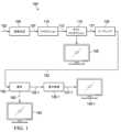
図1は、ビデオキャプチャからビデオコンテンツ表示までの種々の段階を示すビデオ配信パイプライン(100)の例示的な処理を示す。ビデオフレーム(102)のシーケンスは、画像生成ブロック(105)を用いてキャプチャ又は生成される。ビデオフレーム(102)は、デジタル方式、で(例えば、デジタルカメラ等により)キャプチャされ、又はコンピュータにより(例えば、コンピュータアニメーション等を、用いて)生成されてよく、ビデオデータ(107)を提供する。追加で、任意で又は代替として、ビデオフレーム(102)は、フィルムカメラによりフィルム上にキャプチャされてよい。フィルムは、デジタルフォーマットに変換されて、ビデオデータ(107)を提供する。プロダクション段階(110)において、ビデオデータ(107)は、ビデオプロダクションストリーム(112)を提供するために編集される。 Exemplary Image Processing Pipeline
1 illustrates an exemplary process of a video distribution pipeline (100) showing various stages from video capture to video content display. A sequence of video frames (102) are captured or generated using an image generation block (105). The video frames (102) may be digitally captured (e.g., by a digital camera) or computationally generated (e.g., using computer animation) to provide video data (107). Additionally, optionally, or alternatively, the video frames (102) may be captured on film by a film camera. The film is converted to a digital format to provide the video data (107). In a production stage (110), the video data (107) is edited to provide a video production stream (112).
プロダクションストリーム(112)のビデオデータは、次に、ポストプロダクション編集(115)のためにプロセッサに提供される。ポストプロダクション編集(115)は、ビデオ制作者の創造的意図に従い画像品質を向上するため又は特定の外観を達成するために、画像の特定領域の色又は明るさの調整又は変更を含んでよい(例えば、自動的に、手動で、部分的に自動で部分的に手動で、等)。これは、時に、「色タイミング」又は「色グレーディング」と呼ばれる。他の編集(例えば、、シーン選択、順序付け、手動及び/又は自動シーンカット情報生成、画像クロッピング、コンピュータの生成した視覚特殊効果の追加、等)が、コンテンツマッピング及び/又はカラーグレーディングを介して、チェーンドリシェーピング関数のパイプラインなどへの元の入力ビデオ信号を生成するために、ポストプロダクション編集(115)において実行されてよい。The video data of the production stream (112) is then provided to a processor for post-production editing (115). Post-production editing (115) may include adjusting or modifying the color or brightness of certain areas of the image (e.g., automatically, manually, partially automatically and partially manually, etc.) to improve image quality or achieve a particular look according to the video producer's creative intent. This is sometimes referred to as "color timing" or "color grading". Other editing (e.g., scene selection, ordering, manual and/or automatic scene cut information generation, image cropping, addition of computer-generated visual special effects, etc.) may be performed in the post-production editing (115) to produce the original input video signal via content mapping and/or color grading, to a pipeline of chained reshaping functions, etc.
元の入力ビデオ信号は、アップストリーミング装置(例えば、エンコーダ、トランスコーダ、プロダクションスタジオシステム、コンテンツ集約及び/又は配信サーバ、ストリーミングサーバなど)、又はポストプロダクションブロック(115)及び/又はその中のコーディングブロック(120)によって使用されて、画像の1つ、2つ又はそれ以上の基準色等級を生成するとともに、(例えば、予測誤差の最小化、制約なし若しくは制約あり最適化問題に対する閉じた形式の解などによって)1つ、2つ又はそれ以上の基準色等級と各々同じ又は厳密に近似する1つ、2つ又はそれ以上のリシェープド色等級を生成するために使用されるチェーンドリシェーピング関数を生成する。The original input video signal is used by an upstream device (e.g., an encoder, transcoder, production studio system, content aggregation and/or distribution server, streaming server, etc.) or a post-production block (115) and/or a coding block (120) therein to generate one, two or more reference color classes of the image and a chain reshaping function that is used to generate one, two or more reshaped color classes that are each the same as or closely approximate the one, two or more reference color classes (e.g., by minimizing prediction error, closed-form solution to an unconstrained or constrained optimization problem, etc.).
基準色等級及び/又はリシェープド色等級は、同じシーン又は意味的内容を描写する対応する参照画像の異なるセット又はシーケンスを含むことができるが、以下:異なるダイナミックレンジレベル、異なる色空間、異なるEOTF、異なる色空間タイプ、など、のうちの1つ又は複数において異なる場合がある。例えば、これらの基準色等級及び/又はリシェープド色等級は、異なるビデオコーデック及び/又は異なる画像処理能力及び/又はiOS装置、Android装置、タブレットコンピュータ、ラップトップコンピュータ、デスクトップコンピュータ、異なる表示能力のテレビなどの異なるユーザ装置用に最適化されたユーザ知覚可能な視覚品質を有する画像を含むことができる。幾つかの動作シナリオでは、基準色等級を厳密に近似するリシェープド色等級は、一部又は全部のチェーンドリシェーピング関数の一部又は全部の演算パラメータとビデオ信号に符号化された色等級とを含むビデオ信号の受信装置によって、より効率的に(例えば、より少ない計算コストで、より少ない時間で、など)送信、復号又は再構成されてよい。例示的なリシェーピング動作は、G-Mによる米国特許10,080,026「Signal reshaping approximation」に記載されている。その全体の内容は、ここに完全に記載されているかのように参照によりここに組み込まれている。The reference color classes and/or reshaped color classes may include different sets or sequences of corresponding reference images depicting the same scene or semantic content, but may differ in one or more of the following: different dynamic range levels, different color spaces, different EOTFs, different color space types, etc. For example, these reference color classes and/or reshaped color classes may include images with different video codecs and/or different image processing capabilities and/or user-perceivable visual qualities optimized for different user devices, such as iOS devices, Android devices, tablet computers, laptop computers, desktop computers, televisions with different display capabilities, etc. In some operating scenarios, the reshaped color classes that closely approximate the reference color classes may be transmitted, decoded, or reconstructed more efficiently (e.g., with less computational cost, in less time, etc.) by a receiving device of a video signal that includes some or all of the operational parameters of some or all of the Chain Reshaping Functions and the color classes encoded in the video signal. An exemplary reshaping operation is described in U.S. Patent 10,080,026, "Signal reshaping approximation," to G-M, the entire contents of which are incorporated herein by reference as if fully set forth herein.
幾つかの動作シナリオでは、コーディングブロック(120)は、ポストプロダクションブロック(115)から生成された元の入力ビデオ信号(例えば、入力色等級、HLGRec.2020ビデオ信号など)を受信する。コンテンツマッピング及び/又はカラーグレーディング/タイミングツールを使用して、元の入力ビデオ信号から1、2、又はそれ以上の基準色等級を生成することができる。入力ビデオ信号及び基準色等級の各々は、同じ視覚シーン又は意味コンテンツのセットを表す。基準色等級は、手動、自動、又は手動と自動の組み合わせの画像処理演算によって実行されるコンテンツマッピング及び/又はカラーグレーディングを介して、元の入力ビデオ信号から導出することができる。In some operating scenarios, the coding block (120) receives an original input video signal (e.g., an input color grade, an HLGRec.2020 video signal, etc.) generated from the post-production block (115). One, two, or more reference color grades can be generated from the original input video signal using content mapping and/or color grading/timing tools. Each of the input video signal and the reference color grades represent the same visual scene or set of semantic content. The reference color grades can be derived from the original input video signal via content mapping and/or color grading performed by manual, automatic, or a combination of manual and automatic image processing operations.
図示の目的のためだけに、元の入力ビデオ信号は、例えば、ポストプロダクションブロック(115)からコーディングブロック(120)によって受信され、HDR画像117の入力色等級を表す。リシェープド色等級によって近似される基準色等級における参照画像は、元の入力ビデオ信号内のHDR画像(117)から(例えば、Dolby Laboratories, Inc., San Francisco, Californiaなどから市販されているDolby Visionコーディングツールなどのビデオ符号化ツールの適切なプロファイルを使用して)コンテンツマッピングされてよい。幾つかの実施形態では、製作後編集115の間に、HDR画像117は、高ダイナミックレンジをサポートするHDR参照ディスプレイ125で、HDR画像117に対してポストプロダクション編集を実行しているカラリストにより閲覧される。For illustrative purposes only, an original input video signal is received by the coding block (120), e.g., from the post-production block (115), and represents the input color gamut of the HDR image 117. A reference image in a standard color gamut that is approximated by the reshaped color gamut may be content-mapped (e.g., using an appropriate profile in a video coding tool, such as a Dolby Vision coding tool available from Dolby Laboratories, Inc., San Francisco, California, etc.) from the HDR image (117) in the original input video signal. In some embodiments, during
コーディングブロック(120)は、入力ビデオ信号内の画像を中間及び/又は最終的なリシェープド色等級のリシェープド画像にマッピングするために使用されるパイプラインで、チェーンドリシェーピング関数のための演算パラメータの複数のセットを生成するために、本明細書に記載されているように、一部又は全部のチェーンド最適化演算を実装することができる。幾つかの動作シナリオでは、中間及び最終的なリシェープド色等級から選択された(例えば、単一の、等)選択されたリシェープド色等級(例えば、SDR色等級、モバイル装置用のSDR色等級、SDRテレビ用のSDR色等級など)は、コーディングブロック(120)により、符号化ビットストリーム(122)へと圧縮/符号化され得る。チェーンドリシェーピング関数(例えば、逆方向リシェーピング関数、逆リシェーピング関数など)のための演算パラメータの複数のセットの一部又は全部は、画像メタデータの一部として同じ符号化ビットストリームに含まれるか、符号化され得る。The coding block (120) may implement some or all of the chained optimization operations as described herein to generate multiple sets of operation parameters for the chained reshaping functions in the pipeline used to map images in the input video signal to reshaped images of intermediate and/or final reshape color classes. In some operating scenarios, a selected (e.g., single, etc.) reshape color class (e.g., SDR color class, SDR color class for mobile devices, SDR color class for SDR televisions, etc.) selected from the intermediate and final reshape color classes may be compressed/encoded by the coding block (120) into the encoded bitstream (122). Some or all of the multiple sets of operation parameters for the chained reshaping functions (e.g., inverse reshaping function, inverse reshaping function, etc.) may be included or encoded in the same encoded bitstream as part of the image metadata.
コーディングブロック120は、符号化ビットストリーム122を生成するために、ATSC、DVB、DVD、Blu-Ray(登録商標)、及び他の配信フォーマットにより定義されるような、オーディオ及びビデオエンコーダを含んでよい。The
一部の運用シナリオでは、符号化ビットストリーム122は、広範な種類のSDR表示装置(例えば、SDRディスプレイ、等)との後方互換性のあるビデオ信号(例えば、8ビットSDRビデオ信号、10ビットSDRビデオ信号、等)を表してよい。非限定的な例では、再成形SDR画像と共に符号化されたビデオ信号は、単一レイヤの下位互換性のあるビデオ信号であってよい。ここで、「単一レイヤの下位互換性のあるビデオ信号」は、単一の信号レイヤのSDRディスプレイのために特に最適化された又はカラーグレーディングされたSDR画像を運ぶビデオ信号を表してよい。単一レイヤのビデオコーディング操作の例は、G-Mによる米国特許出願公開第2019/0110054号「Encoding and decoding reversible production-quality single-layer video signals」に記載されている。その全体の内容は、ここに完全に記載されているかのように参照によりここに組み込まれている。In some operational scenarios, the encoded
チェーンドリシェーピング関数のための演算パラメータの複数のセットは、1つの色等級の復号画像から他の色等級の再構成画像を生成するために、ビデオ信号又は符号化ビットストリームの受信装置によって、復号され、予測動作に使用され得る。(上流)コーディングブロック(120)によって生成されるように、チェーンドリシェーピング関数のための演算パラメータの複数のセットを有する予測演算(例えば、逆方向リシェーピング演算、逆トーンマッピング演算など)を用いて、再構成画像に対して、1つ以上の異なるビデオ品質レベルを生成することができる。これらの異なるビデオ品質レベルは、エンコーダ側の中間及び/又は最終的なリシェープド色等級のような、1つ以上の異なる色等級に各々対応することができる。Multiple sets of operation parameters for the Chained Reshaping function can be decoded and used in a prediction operation by a receiving device of a video signal or encoded bitstream to generate a reconstructed image of one color class from a decoded image of another color class. Using a prediction operation (e.g., an inverse reshaping operation, an inverse tone mapping operation, etc.) with multiple sets of operation parameters for the Chained Reshaping function, one or more different video quality levels can be generated for the reconstructed image as generated by the (upstream) coding block (120). These different video quality levels can each correspond to one or more different color classes, such as intermediate and/or final reshaped color classes at the encoder side.
幾つかの動作シナリオでは、復号画像は、参照SDR色等級を近似するために、カラーグレーディングされたHDR画像(117)からアップストリームビデオエンコーダ(例えば、コーディングブロック(120)等を用いる)によって順方向にリシェーピングされたSDR画像を表す。再構成画像は、符号化ビットストリーム(122)内で送信される画像メタデータ内の演算パラメータの複数のセットで指定されたリシェーピング関数を使用して復号画像から生成され、基準SDR色等級以外の他の中間及び/又は最終基準色等級を近似する画像を表す。In some operating scenarios, the decoded image represents an SDR image forward reshaped by an upstream video encoder (e.g., using coding block (120)) from the color-graded HDR image (117) to approximate a reference SDR color grade. The reconstructed image represents an image generated from the decoded image using a reshaping function specified in multiple sets of operation parameters in the image metadata transmitted in the encoded bitstream (122) and approximating other intermediate and/or final reference color grades other than the reference SDR color grade.
追加で、任意で、又は代替として、符号化ビットストリーム(122)は、下流のデコーダが復号画像又は逆方向リシェープド画像に対して表示管理操作を実行するために使用できる表示管理(display management (DM))メタデータを含むがこれに限定されない追加の画像メタデータにより符号化され、ターゲットディスプレイ上でのレンダリングに最適化された表示画像を生成する。これらの画像は、中間及び/又は最終基準色投球が比較的高い視覚品質を提供する参照ディスプレイと同じ表示機能を有していてもいなくてもよい。Additionally, optionally, or alternatively, the encoded bitstream (122) may be encoded with additional image metadata, including, but not limited to, display management (DM) metadata that a downstream decoder can use to perform display management operations on the decoded image or the reverse reshaped image to generate display images optimized for rendering on a target display. These images may or may not have the same display capabilities as a reference display for which the intermediate and/or final reference color throws provide relatively high visual quality.
符号化ビットストリーム122は、次に、モバイル装置、ハンドセット、タブレットコンピュータ、復号及び再生装置、メディアソース装置、メディアストリーミングクライアント装置、テレビジョンセット(例えば、スマートTV、等)、セットトップボックス、映画劇場、等のような受信機へと下流へ配信される。受信機(又は下流装置)では、符号化ビットストリーム(122)を復号ブロック(130)によって復号して復号画像182を生成する。これは、コーディングブロック(120)によってビットストリームに符号化された画像(例えば、順方向リシェープドSDR画像など)と同じであってもよく、コーディングブロック(120)によって実行される圧縮と復号ブロック(130)によって実行される伸長で発生する量子化誤差の影響を受ける。The encoded
受信機が復号画像(182)のレンダリングをサポートするターゲットディスプレイ140で動作する(又は接続されているか、動作可能にリンクされている)運用シナリオでは、復号ブロック(130)は、コーディングビットストリーム(122)(例えば、その単一レイヤなど)から画像(182)を復号し、復号画像(182)(例えば、順方向リシェーピングSDR画像など)をターゲットディスプレイ(140)でのレンダリングに直接又は間接的に使用できる。In an operational scenario in which the receiver operates with (or is connected to or operably linked to) a
幾つかの運用シナリオでは、ターゲットディスプレイ(140)はSDR参照ディスプレイ(125)と同様の特性を持ち、復号画像(182)は、ターゲットディスプレイ(140)で直接監視可能な順方向リシェープドSDR画像である。In some operational scenarios, the target display (140) has similar characteristics to the SDR reference display (125), and the decoded image (182) is a forward reshaped SDR image that can be directly viewed on the target display (140).
幾つかの実施例では、受信機は、復号画像(182)が最適化された参照ディスプレイとは異なる表示機能を持つターゲットディスプレイで動作する(又は、ターゲットディスプレイに接続又は動作可能にリンクされる)。画像メタデータ(又はコンポーザメタデータ)内の、チェーンドリシェーピング関数の演算パラメータの複数のセットの一部又はすべてを使用して、ターゲットディスプレイに最適化された復号画像(182)から画像を構成又は再構成できる。In some embodiments, the receiver operates with (or is connected or operably linked to) a target display having different display capabilities than the reference display for which the decoded image (182) was optimized. Images can be composed or reconstructed from the decoded image (182) optimized for the target display using some or all of the multiple sets of operation parameters of the Chain Reshaping function in the image metadata (or composer metadata).
例えば、受信機は、復号画像(182)よりも高ダイナミックレンジ(例えば、100ニト、200ニト、300ニト、500ニト、1,000ニト、4,000ニト、1万ニト、又はそれ以上など)をサポートするHDRターゲットディスプレイ140-1で動作する場合がある。受信機は、符号化ビットストリーム122(例えば、その中のメタデータコンテナなど)から画像メタデータを抽出し、画像メタデータ(又はコンポーザメタデータ)内の演算パラメータの複数のセットを使用して、順方向リシェープドSDR画像などの復号画像(182)から画像132-1を構成又は再構成できる。For example, the receiver may operate with an HDR target display 140-1 that supports a higher dynamic range (e.g., 100 nits, 200 nits, 300 nits, 500 nits, 1,000 nits, 4,000 nits, 10,000 nits, or more) than the decoded image (182). The receiver can extract image metadata from the encoded bitstream 122 (e.g., a metadata container therein) and use multiple sets of computation parameters in the image metadata (or composer metadata) to compose or reconstruct an image 132-1 from the decoded image (182), such as a forward reshaped SDR image.
幾つかの運用シナリオでは、再構成画像(132-1)は、受信機と連動して動作するターゲットディスプレイと同じか又は互換性のあるディスプレイ上で閲覧するために最適化された再構成された(例えば、HDR、EDR、1000ニトの表示装置に最適化された画像、4000ニトの表示装置に最適化された画像、等)の画像を表す。受信機は、ターゲットディスプレイ上でレンダリングするために再構成画像(132-1)を直接使用する場合がある。In some operational scenarios, the reconstructed image (132-1) represents a reconstructed image (e.g., HDR, EDR, an image optimized for a 1000 nits display, an image optimized for a 4000 nits display, etc.) optimized for viewing on a display that is the same as or compatible with the target display operating in conjunction with the receiver. The receiver may use the reconstructed image (132-1) directly for rendering on the target display.
幾つかの運用シナリオでは、再構成画像(132-1)は、受信機と連動して動作するターゲットディスプレイ(140-1)と同じではない(例えば、参照、等の)ディスプレイ上で閲覧するのに最適化された再構成画像を表す。表示管理ブロック(例えば、135-1など)は、受信機、ターゲットディスプレイ(140-1)、又は別の装置内にあってもよく、ターゲットディスプレイ(140-1)の特性に適合したディスプレイマップド信号(137-1)を生成することによって、再構成画像(132-1)をターゲットディスプレイ(140-1)の特性にさらに調整する。表示画像又は調整された再構成画像は、ターゲットディスプレイ(140-1)上でレンダリングされてよい。In some operational scenarios, the reconstructed image (132-1) represents a reconstructed image optimized for viewing on a display (e.g., a reference, etc.) that is not the same as the target display (140-1) operating in conjunction with the receiver. A display management block (e.g., 135-1, etc.), which may be in the receiver, the target display (140-1), or another device, further adjusts the reconstructed image (132-1) to the characteristics of the target display (140-1) by generating a display-mapped signal (137-1) that matches the characteristics of the target display (140-1). The display image or the adjusted reconstructed image may be rendered on the target display (140-1).
<チェーンドリシェーピング関数のパイプライン>
図2Aは、チェーンドリシェーピング関数の例示的なパイプラインを示す。これらのチェーンドリシェーピング関数は、本明細書に記載されるような最適化方法又は手順を使用して生成又は構築することができる。 <Pipeline of Chained Reshaping Functions>
2A shows an example pipeline of Chained Reshaping functions, which can be generated or constructed using optimization methods or procedures as described herein.
チェーンドリシェーピング関数のパイプラインへの(元の)入力ビデオ信号(又はその中の入力画像)を、s<0>と表す。入力信号(又はその中の入力画像)のi番目のピクセルは,s<0>,iとして示され、入力色空間(又は入力ドメイン)の3つのチャネル、各々、(sy<0>,i, sC0<0>,i, sC1<0>,i)として示される。 The (original) input video signal (or input image therein) to the pipeline of Chained Reshaping functions is denoted as s<0> . The i-th pixel of the input signal (or input image therein) is denoted as s<0>,i , and the three channels of the input color space (or input domain), respectively, are denoted as (sy<0>,i , sC0<0>,i , sC1<0>,i ).
チェーンドリシェーピング関数のパイプラインは、一緒に連結されたK個のリシェーピング関数を含み、Kは1より大きい整数である。チェーンドリシェーピング関数のパイプラインの中のk番目のリシェーピング関数は、Rk()と表され、r<k+1>として表される対応する参照ビデオ信号(又はその中の対応する参照画像)を持つことができ、又は割り当てることができる。ここで、k=0、...、K-1である。 A pipeline of chained reshaping functions includes K reshaping functions concatenated together, where K is an integer greater than 1. The kth reshaping function in the pipeline of chained reshaping functions is denoted as Rk () and may have or be assigned a corresponding reference video signal (or a corresponding reference picture therein) denoted as r<k+1> , where k=0,...,K-1.
k番目のリシェーピング関数Rk()の参照信号(又はその中の参照画像)r<k+1>のi番目のピクセルを、(ry<k+1>,i,rC0<k+1>,i,rC1<k+1>,i)と表す。k番目のリシェーピング関数Rk()への入力ビデオ信号(又はその中の入力画像)及びk番目のリシェーピング関数Rk()からの出力又はリシェープドビデオ信号(又はその中の出力又はリシェープド画像)を、各々、s<k>及びs<k+1>と表し、ここで、k=0、...、K-1である。k番目のリシェーピング関数Rk()は、次のように、入力信号(又はその中の入力画像)s<k>を出力信号(又はその中の出力画像)s<k+1>に順方向にリシェーピングするために適用できる。
多くの運用シナリオでは、チェーンドリシェーピング関数のパイプラインからの最終出力又はリシェープドビデオ信号(又はその中の最終出力画像)は、次のように、最初又は元の入力ビデオ信号(又はその中の最初又は元の入力画像)と等しない。
k番目のリシェーピング関数の場合、その出力信号s<k+1>は、次のように、参照信号r<k+1>にできるだけ近い(例えば、エラー閾値/測定値などに応じて、最小化/最適化手順に従う)必要がある。
その結果、チェーンドリシェーピング関数のパイプライン全体における最適化リシェーピング関数の構成/生成は、次のように、個々のリシェーピング関数の個々の最適化問題の線形結合(に対する解)として定式化できる。
エンドツーエンドの最適化は、解決が比較的困難であり又は計算集約的である可能性があるが、順次最適化などのより優れた効率的な方法を使用して、この問題に取り組むことができる。End-to-end optimization can be relatively difficult or computationally intensive to solve, but better and more efficient methods such as sequential optimization can be used to tackle this problem.
図2Bは、先に述べたように、Dolby Vision Profile8.4からDolby Vision Profile8.2への変換を実装するために使用できる、チェーンドリシェーピング関数の(具体的な)パイプラインの例を示している。Figure 2B shows an example (concrete) pipeline of chained reshaping functions that can be used to implement the conversion from Dolby Vision Profile 8.4 to Dolby Vision Profile 8.2, as described above.
図2Bに示されるように、チェーンドリシェーピング関数のパイプラインへの第1又は元のビデオ信号s<0>は、入力HLG(例えば、R.2020など)信号である。チェーンドリシェーピング関数のパイプライン内の第1リシェーピング関数R0は、参照信号r<1>を持っているか又は割り当てられており、参照信号r<1>は、HLG-SDR API(Application Programming Interface)又は市販のツールキットを使用して入力HLG信号から導出又は変換することができる。 As shown in Figure 2B, the first or original video signal s<0> to the pipeline of chained reshaping functions is an input HLG (e.g. R.2020, etc.) signal. The first reshaping functionR0 in the pipeline of chained reshaping functions has or is assigned a reference signal r<1> , which can be derived or converted from the input HLG signal using the HLG-SDR API (Application Programming Interface) ora commercially available toolkit.
出力又はリシェープドビデオ信号s<1>は、チェーンドリシェーピング関数のパイプライン内の第1リシェーピング関数R0を第1又は元の入力ビデオ信号s<0>に適用することによって生成することができ、言い換えると、第1リシェーピング関数R0に基づいて第1又は元の入力ビデオ信号s<0>をリシェーピングすることによって生成することができる。図2Bに示すように、出力又はリシェープドビデオ信号s<1>は、リシェープドSDR信号であってもよい。リシェープドSDR信号は、参照信号r<1>と同じであってもよく又は厳密に近似していてもよい。 The output or reshaped video signal s<1> may be generated by applying a first reshaping functionR0 in a pipeline of chained reshaping functions to the first or original input video signal s<0> , in other words, by reshaping the first or original input video signal s<0> based on the first reshaping functionR0 . As shown in FIG. 2B, the output or reshaped video signal s<1> may be a reshaped SDR signal. The reshaped SDR signal may be the same as or closely approximate the reference signal r<1> .
リシェープドSDR信号(s<1>)は、第2リシェーピング関数R1への入力ビデオ信号として使用することができる。第2参照信号r<2>は、基準PQ信号であってもよい。基準PQ信号は、HLG後方互換コーデックのようなビデオコーデックを使用して、又はBT.2100規格のような関連するビデオコーディング規格又はその中で定義されるプロファイルを実装する他のビデオコーデックを使用して、第1又は元の入力ビデオ信号(又は入力HLGビデオ信号)から導出又は変換することができる。 The reshaped SDR signal (s<1> ) can be used as an input video signal to the second reshaping functionR1 . The second reference signal r<2> can be a reference PQ signal. The reference PQ signal can be derived or converted from the first or original input video signal (or the input HLG video signal) using a video codec such as an HLG backward compatible codec, or using any other video codec implementing a related video coding standard such as the BT.2100 standard or a profile defined therein.
出力又はリシェープドビデオ信号s<2>は、チェーンドリシェーピング関数のパイプライン内の第2リシェーピング関数R1をリシェープドビデオ信号s<1>に適用することによって、言い換えると、第1リシェーピング関数R1に基づいてリシェープドビデオ信号s<1>をリシェーピングすることによって生成することができる。出力又はリシェープドビデオ信号(s<2>)は、PQ信号であってもよい。PQ信号は、第2参照信号r<2>又は参照PQ信号と同じであってもよく又は厳密に近似していてもよい。 The output or reshaped video signal s<2> may be generated by applying a second reshaping function R<1> in a pipeline of chained reshaping functions to the reshaped video signal s<1> , in other words, by reshaping the reshaped video signal s<1> based on the first reshaping function R<1> . The output or reshaped video signal (s<2> ) may be a PQ signal. The PQ signal may be the same as or closely approximate the second reference signal r<2> or the reference PQ signal.
図示のように、第1リシェーピング関数:

<順次/チェーンド最適化>
様々な予測子を使用して、例えば、順次最適化プロセスを使用して、ここで説明するようなチェーンドリシェーピング関数を構成又は生成できる。これらの予測子は、テンソル積Bスプライン(Tensor Product B-Spline (TPB))予測子や非TPB予測子などの高度な予測子であってよい。 Sequential/Chained Optimization
A variety of predictors can be used to construct or generate chained reshaping functions as described herein, for example, using a sequential optimization process. These predictors can be advanced predictors such as Tensor Product B-Spline (TPB) predictors or non-TPB predictors.
幾つかの運用シナリオでは、チェーンドリシェーピング関数のパイプライン全体でリシェーピング関数を構築するための最適化問題は、2つの最適化問題に分解できる。1つはルマチャネルに使用されるリシェーピング関数/マッピング(ルマリシェーピング関数と呼ばれることがある)を構成するための最適化問題であり、もう1つはクロマチャネルのリシェーピング関数/マッピング(クロマリシェーピング関数と呼ばれることがある)を構成するための最適化問題である。例えば、リシェーピング関数のパイプライン内のリシェーピング関数は、(ルマチャネル内の入力コードワード又は入力ルマコードワードをルマチャネル内の出力コードワード又は出力ルマコードワードにリシェーピングする)ルマリシェーピング関数/マッピングと、(ルマ及びクロマチャネル内の入力コードワード又は入力ルマ及びクロマコードワードをクロマチャネル内の出力コードワード又は出力クロマコードワードにリシェーピングする)クロマリシェーピング関数/マッピングを含むことができる。In some operational scenarios, the optimization problem for constructing the reshaping functions in the entire pipeline of chained reshaping functions can be decomposed into two optimization problems: one for constructing the reshaping function/mapping used for the luma channel (sometimes called luma reshaping function) and another for constructing the reshaping function/mapping for the chroma channels (sometimes called chroma reshaping function). For example, the reshaping functions in the pipeline of reshaping functions can include a luma reshaping function/mapping (which reshapes an input codeword or input luma codeword in the luma channel to an output codeword or output luma codeword in the luma channel) and a chroma reshaping function/mapping (which reshapes an input codeword or input luma and chroma codeword in the luma and chroma channels to an output codeword or output chroma codeword in the chroma channel).
幾つかの運用シナリオでは、ルマチャネルの最適化問題を解決する際に、CDFマッチング技術を使用して、クロマ及び/又はルマリシェーピング関数/マッピング(例えば、マルチピース多項式、1次元ルックアップテーブル又は1D LUT、3次元ルックアップテーブル又は3D LUTの一部など)を構成又は生成することができる。追加で、任意で、又は代替として、クロマ及び/又はルマリシェーピング関数/マッピングは、マルチカラーチャネル多重回帰(multiple color channel multiple regression (MMR))予測ベース技術などのクロスカラーチャネル予測因子を使用して構成又は生成することができる。追加で、任意で、又は代替として、クロマ及び/又はルマリシェーピング関数/マッピングは、基底関数としてBスプライン(B-Spline)関数を使用するテンソル積Bスプライン(tensor product B-spline (TPB))予測ベース技術などのクロスカラーチャネル予測因子を使用して構成又は生成することができる。In some operational scenarios, when solving the luma channel optimization problem, the CDF matching technique may be used to construct or generate the chroma and/or luma shaping function/mapping (e.g., a multi-piece polynomial, a one-dimensional lookup table or 1D LUT, a portion of a three-dimensional lookup table or 3D LUT, etc.). Additionally, optionally, or alternatively, the chroma and/or luma shaping function/mapping may be constructed or generated using a cross-color channel predictor, such as a multiple color channel multiple regression (MMR) prediction-based technique. Additionally, optionally, or alternatively, the chroma and/or luma shaping function/mapping may be constructed or generated using a cross-color channel predictor, such as a tensor product B-spline (TPB) prediction-based technique using B-Spline functions as basis functions.
例示的な累積密度関数(cumulative density function (CDF))マッチング演算は、参照により本願明細書に全体が記載されたように本願明細書に組み込まれる2017年9月11日出願のPCT出願番号PCT/US2017/50980;2016年10月5日出願の米国仮特許出願番号第62/404,307号(米国特許出願公開番号第2018/0098094号として2018年4月5日に公開された)に記載されている。MMRに基づく演算の例は、米国特許8,811,490に記載されており、その全内容は、参照によりここに完全に記載されているものとして組み込まれる。TPBに基づく演算の例は、米国仮出願番号第62/908,770号(代理人整理番号第60175-0417号)、2019年10月1日出願、名称「TENSOR-PRODUCT B-SPLINE PREDICTOR」に記載されており、該出願は参照により、その全体が本明細書に完全に記載されているものとして援用される。Exemplary cumulative density function (CDF) matching operations are described in PCT Application No. PCT/US2017/50980, filed Sep. 11, 2017, which are incorporated herein by reference as if fully set forth herein; U.S. Provisional Patent Application No. 62/404,307, filed Oct. 5, 2016 (published Apr. 5, 2018 as U.S. Patent Application Publication No. 2018/0098094), which are incorporated herein by reference in their entirety. An example of an MMR-based operation is described in U.S. Patent No. 8,811,490, the entire contents of which are incorporated herein by reference as if fully set forth herein. Examples of calculations based on TPB are described in U.S. Provisional Application No. 62/908,770 (Attorney Docket No. 60175-0417), filed October 1, 2019, entitled "TENSOR-PRODUCT B-SPLINE PREDICTOR," which is incorporated by reference in its entirety as if fully set forth herein.
第1例では、チェーンドリシェーピング関数のパイプラインにおけるk番目のリシェーピング関数のためのMMRベースのクロママッピング関数/マッピング(又はMMR予測子)は、以下のように構築又は生成することができる。In a first example, an MMR-based chroma mapping function/mapping (or MMR predictor) for the kth reshaping function in a pipeline of chained reshaping functions can be constructed or generated as follows:
入力ビデオ信号(又はその中の入力画像)のi番目のピクセルのためのMMR展開形式を、以下のように示す:
すべてのP個のピクセルのMMR展開形式は、次のように入力ベクトルに収集できる:
観測(又は基準/ターゲット)のクロマ信号又はベクトルは、次のように基準/ターゲットビデオ信号(又はその中の基準/ターゲット画像)のクロマコードワードに基づいて形成できる。ここで、chは、c0若しくはCbチャネルであるか、又はc1若しくはCrチャネルであるか、のいずれかである。
MMR係数は、mch<k>として表され、次のようなマトリクス形式を使用して、出力又はリシェープドビデオ信号(又はその中の出力又はリシェープド画像)の出力又はリシェープドクロマコードワードを予測するために使用できる。
MMR係数mch<k>は、次のように定式化された最適化問題を解くことによって最適化できる。
例えば、最適化されたMMR係数は、次のように式(9)の最適化問題の最小二乗解によって見付けられ又は生成される。
幾つかの運用シナリオでは、チェーンドリシェーピング関数のパイプライン内の各リシェーピング関数、例えばルマ及びクロマリシェーピング関数/そのマッピングは、k=0から開始してK-1まで、順次生成又は構築できる。例えば、チェーンドリシェーピング関数のパイプライン内の各リシェーピング関数内のクロマリシェーピング関数/マッピングは、以下の表1に示すような例示的な最適化手順を使用して、k=0から開始してK-1まで、順次生成又は構築できる。
[表1]
[Table 1]
第2例では、チェーンドリシェーピング関数のパイプラインにおけるk番目のリシェーピング関数のためのTPBベースのクロママッピング関数/マッピング(又はTPB予測子)は、以下のように構築又は生成することができる。In a second example, a TPB-based chroma mapping function/mapping (or TPB predictor) for the kth reshaping function in a pipeline of chained reshaping functions can be constructed or generated as follows:
chカラーチャネルの場合、次の行列を構築できる。
TPBベースのクロマリシェーピング関数/マッピングのために最適化されたTPB演算パラメータは、mch,opt<k>と表され、例えば、上記の式(8)と同様の式を使用して定式化された(グローバルな)TPB最適化問題の最小二乗解によって、次のように構築、生成又は取得することができる。
<チェーンドリシェーピング関数の最適化>
チェーンドリシェーピング関数のパイプラインにおけるリシェーピング関数の性能(例えば、再構成ビデオ信号の精度の向上、予測誤差の最小化、多様なビデオコーデックのサポートなど)を向上するために、様々な最適化アルゴリズム/方法を使用できる。様々な運用シナリオでは、これらの最適化アルゴリズム/方法で制約が使用される場合と使用されない場合がある。 <Optimization of chain reshaping function>
Various optimization algorithms/methods can be used to improve the performance of the reshaping functions in the pipeline of chained reshaping functions (e.g., improve the accuracy of the reconstructed video signal, minimize prediction errors, support a variety of video codecs, etc.) In various operational scenarios, these optimization algorithms/methods may or may not use constraints.
幾つかの運用シナリオでは、制約なしの信号調整のための逆方向誤差減算(BESA (Backward Error Subtraction for signal Adjustment))アルゴリズム/方法と呼ばれることがある反復アルゴリズム/方法を使用して、チェーンドリシェーピング関数のパイプラインでリシェーピング関数の性能を向上させることができる。BESAアルゴリズム/方法の例は、米国仮特許出願番号第63/013,063号、「Reshaping functions for HDR imaging with continuity and reversibility constraints」、G-M. Su, 2020年4月21日出願、米国仮特許出願番号第63/013,807号、「Iterative optimization of reshaping functions in single-layer HDR image codec」、G-M. Su、H. Kadu、2020年4月22日出願、に記載されており、それらの内容は、ここに完全に記載されているかのように、参照によりここに完全に組み込まれている。In some operational scenarios, an iterative algorithm/method, sometimes referred to as a Backward Error Subtraction for signal Adjustment (BESA) algorithm/method, can be used to improve the performance of the reshaping functions in a pipeline of chained reshaping functions. Examples of the BESA algorithm/method are described in U.S. Provisional Patent Application No. 63/013,063, “Reshaping functions for HDR imaging with continuity and reversibility constraints,” G-M. Su, filed April 21, 2020, and U.S. Provisional Patent Application No. 63/013,807, “Iterative optimization of reshaping functions in single-layer HDR image codec,” G-M. Su, H. Kadu, filed April 22, 2020, the contents of which are hereby incorporated by reference in their entireties as if fully set forth herein.
反復アルゴリズム/方法は、T回の反復で実行できる。ここで、Tは、(例えば、事前に設定された、構成された、動的に決定された、予算計上されたなど)1より大きい整数を表す。T反復の各反復(例えば、反復tであり、t=0、...、T-1である)では、まず最適化を順方向に実行して、チェーンドリシェーピング関数のパイプラインでリシェーピング関数を定義又は指定するリシェーピング関数係数を取得又は生成でき、その後、参照信号の変更を逆方向に実行できる。反復アルゴリズム/方法の目標は、エンドツーエンド誤差(例えば、予測された最終的なリシェープドビデオ信号と最終的な基準ビデオ信号との間の差、等)を最小化できるように、各反復tで参照信号r(t)<k>を変更することである。 The iterative algorithm/method may be performed for T iterations, where T represents an integer greater than 1 (e.g., preset, configured, dynamically determined, budgeted, etc.). At each of the T iterations (e.g., iteration t, where t=0, . . . , T-1), an optimization may first be performed forward to obtain or generate reshaping function coefficients that define or specify the reshaping functions in a pipeline of chained reshaping functions, and then a modification of the reference signal may be performed backward. The goal of the iterative algorithm/method is to modify the reference signal r(t)<k> at each iteration t such that an end-to-end error (e.g., difference between a predicted final reshaped video signal and a final reference video signal, etc.) can be minimized.
非限定的な実装例では、反復アルゴリズム/方法は、2つのforループで実装又は実行できる。2つのforループのうちの外側のforループでは、t=0、...、T-1のようにT回の反復に達するまで、反復回数(t)が1つずつ増加又はインクリメントされる。2つのforループのうちの内側のforループでは、第1リシェーピング関数R0から最後のリシェーピング関数RK-1まで、順方向最適化を実行できる。 In a non-limiting implementation example, the iterative algorithm/method may be implemented or performed with two for loops. In the outer for loop, the iteration number (t) is increased or incremented by one until T iterations are reached, such that t=0, ..., T-1. In the inner for loop, a forward optimization may be performed from the first reshaping functionR0 to the last reshaping functionRK-1 .
2つのforループのうちの内側のforループの各反復の最後に、最後から2番目の参照信号から第1参照信号r(t)<1>まで、逆方向参照信号修正を実行できる。幾つかの動作シナリオでは、最後の参照信号r(t)<K>は、固定されており、前述の逆方向参照信号修正は適用されない。これは、チェーンドリシェーピング関数のパイプラインからの出力(又は最後の参照信号)の忠実度を維持し、各反復で最終エラー又は最終コスト関数(値)を変更することによって発生する振動(したがって、収束しないか又は比較的遅く収束すること)を回避するためである。 At the end of each iteration of the inner for loop of the two for loops, backward reference signal correction can be performed from the penultimate reference signal to the first reference signal r(t)<1> . In some operating scenarios, the last reference signal r(t)<K> is fixed and the aforementioned backward reference signal correction is not applied. This is to maintain the fidelity of the output (or the last reference signal) from the pipeline of chained reshaping functions and to avoid oscillations (and therefore no convergence or relatively slow convergence) caused by changing the final error or final cost function (value) at each iteration.
より具体的には、順方向最適化において、(例えば、各々、等)反復tにおいて、各リシェーピング関数(例えば、k番目のリシェーピング関数、等)は、
(1)k=0の場合に最初又は元の入力映像信号(又はその中の最初又は元の入力画像)であり、k≠0の場合に(直前の)先行するリシェーピング関数(例えば、(k-1)番目のリシェーピング関数、など)から出力される更新された入力ビデオ信号(又はその中の更新された入力画像)であるs(t)<K>、及び(2)(直前の)先行する反復の最後に実行される逆方向参照信号修正からの更新された参照ビデオ信号(又はその中の更新された参照画像)であるr(t)<K+1>に基づき、最適化リシェーピング関数係数{m(t),ch,opt<K>}、及び予測信号s(t)<K+1>を取得するために最適化を実行することにより生成又は構成できる。これらの演算は、k=0からK-1までのチェーンドリシェーピング関数のパイプライン内のすべてのリシェーピング関数に対して順次実行することができる。 More specifically, in the forward optimization, at iteration t (e.g., each, etc.), each reshaping function (e.g., the kth reshaping function, etc.) is
Based on (1) s(t)<K>, which is the first or original input video signal (or the first or original input image therein) for k=0 and the updated input video signal (or the updated input image therein) output from the (most recent) preceding reshaping function (e.g., the (k-1)th reshaping function, etc.) for k≠0, and (2) r(t)<K+1> , which is the updated reference video signal (or the updated reference image therein) from the backward reference signal modification performed at the end of the (most recent) preceding iteration, the optimized reshaping function coefficients {m( t),ch,opt<K> } and the predicted signal s(t) <K+1> can be generated or constructed by performing optimization to obtain optimized reshaping function coefficients {m(t),ch,opt<K> } and the predicted signal s(t)<K+1> . These operations can be performed sequentially for all reshaping functions in the pipeline of chained reshaping functions for k=0 to K-1.
各反復(t)の最後に、各カラーチャネルの予測誤差を次のように計算することによって、各kに対して逆方向参照信号修正を実行することができる。

これらの演算は、k=K-1から1までのすべての参照ビデオ信号(最後の参照ビデオ信号を除く)に対して順番に実行できる。These operations can be performed sequentially on all reference video signals from k=K-1 to 1 (except the last reference video signal).
幾つかの運用シナリオでは、関数f()を使用して、参照ビデオ信号(又はその中の参照画像)を変更する方法を決定できる。この関数は、比較的大きなエラーを参照ビデオ信号に逆伝播させるために使用できる。各ピクセル(又はi番目のピクセル)に対して、関数f()は次のように指定又は定義できる。
幾つかの運用シナリオでは、次のように、関数f()で適応スケーリング係数を使用できる。ここで、反復インデックスtが増加すると、以下のようにスケーリング係数が減少する。
反復最適化手順の例を次の表2に示す。
[表2]
[Table 2]
<最適化された反復回数の選択>
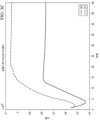
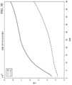
図3Aは、図2Bに示すように、チェーンドリシェーピング関数のパイプラインでリシェーピング関数を構築するために使用される反復最適化アルゴリズム/方法の各反復における、第1リシェーピング関数R0から出力される第1リシェープドSDRビデオ信号(又はその中のリシェープドSDR画像)の歪みの例を示す。図3Bは、反復最適化アルゴリズム/方法の各反復における、第2リシェーピング関数R1から出力されるリシェープドHDRビデオ信号(又はその中のリシェープドHDR画像)の歪みの例を示す。 <Selecting the optimal number of iterations>
Figure 3A shows an example of distortion of a first reshaped SDR video signal (or a reshaped SDR image therein) output from a first reshaping functionR0 at each iteration of an iterative optimization algorithm/method used to build reshaping functions in a pipeline of chained reshaping functions as shown in Figure 2B. Figure 3B shows an example of distortion of a reshaped HDR video signal (or a reshaped HDR image therein) output from a second reshaping functionR1 at each iteration of an iterative optimization algorithm/method used to build reshaping functions in a pipeline of chained reshaping functions as shown in Figure 2B.
図3Bに示すように、第2リシェーピング関数から出力されるリシェープドHDRビデオ信号の歪みは、反復回数が増加すると、一定レベル以下で飽和するまで徐々に減少する。対照的に図3Aに示すように、第1リシェーピング関数から出力されるリシェープドSDRビデオ信号の歪みは、反復回数が増加するき、一定レベル又はそれ以下で飽和することなく増加し続ける。As shown in FIG. 3B, the distortion of the reshaped HDR video signal output from the second reshaping function gradually decreases as the number of iterations increases until it saturates below a certain level. In contrast, as shown in FIG. 3A, the distortion of the reshaped SDR video signal output from the first reshaping function continues to increase as the number of iterations increases without saturating at or below a certain level.
中間のリシェープドビデオ信号の忠実度を向上させるために、反復回数が最終ラウンド(又はT回の反復)に達する前にリシェーピング係数を取得するか、又はチェーンドリシェーピング関数のパイプライン内の特定のリシェーピング関数を定義するために使用することができる。言い換えると、最終ラウンド(又はT回の反復)まで、表2に示す反復最適化アルゴリズム/方法を完了する代わりに、反復toptでのリシェーピング係数を取得することができる。ここで、topt<Tである。 In order to improve the fidelity of the intermediate reshaped video signal, the reshaping coefficients can be obtained before the iteration number reaches the final round (or T iterations), or can be used to define a specific reshaping function in the pipeline of chained reshaping functions. In other words, instead of completing the iterative optimization algorithm/method shown in Table 2 until the final round (or T iterations), the reshaping coefficients at iteration topt can be obtained, where topt <T.
第1例では、客観的な方法を使用して、最適な反復回数toptを選択又は取り出すことができる。図3A及び図3Bに示すような反復に渡る歪みを示す収束曲線を使用して、第1リシェーピング関数R0から出力される第1リシェープドビデオ信号の歪みと、第2リシェーピング関数R1から出力される第2リシェープドビデオ信号の歪みとの間に最良のトレードオフを有する特定の反復インデックス(又は最適な反復回数topt)を識別、選択又は取り出すことができる。例えば、図3Bに示されるようなR1歪みは、R1収束曲線上のニーポイントである反復#8のような特定の反復回数で飽和し始める。このニーポイントは、R1収束曲線が絶対値で最大の1次微分変化を有する(又は絶対値又は大きさで最大の2次微分を有する)場所で識別又は見つけることができる。図3Aに示されるように、図3Aに示されるようなR0歪みはまた、R0収束曲線上の特定の反復回数(又はこの例では反復8)で比較的小さな歪みを有する。 In the first example, an objective method can be used to select or retrieve the optimal iteration number topt . Using the convergence curves showing distortion over iterations as shown in FIG. 3A and FIG. 3B, a particular iteration index (or optimal iteration number t opt ) that has the best tradeoff between the distortion of the first reshaped video signal output from the first reshaping functionR0 and the distortion of the second reshaped video signal output from the second reshaping functionR1 can be identified, selected or retrieved. For example, theR1 distortion as shown in FIG. 3B starts to saturate at a particular iteration number such as iteration #8 , which is a knee point on the R1 convergence curve. This knee point can be identified or found where theR1 convergence curve has the largest first derivative change in absolute value (or has the largest second derivative in absolute value or magnitude). As shown in FIG. 3A, theR0 distortion as shown in FIG. 3A also has a relatively small distortion at a particular iteration number (or
第2例では、主観的な方法を使用して、最適な反復回数toptを選択又は取り出すことができる。例えば、各反復で生成又は取得されたリシェーピング係数の各セットをテスト画像のバッチに適用して、異なるリシェープドビデオ信号間の最適なトレードオフを主観的に決定するのを助けるために、ユーザ(又は人間)によってレビューできるリシェープド画像を生成することができる。これらの操作の一部は手動で実行されてもよく、これらの操作の他の一部は自動的に実行されてもよい。 In a second example, a subjective method may be used to select or derive the optimal number of iterations topt . For example, each set of reshaping coefficients generated or obtained at each iteration may be applied to a batch of test images to generate reshaped images that can be reviewed by a user (or human) to help subjectively determine the optimal tradeoff between different reshaped video signals. Some of these operations may be performed manually and other parts of these operations may be performed automatically.
<逆勾配ベースアルゴリズム>
逆方向参照信号修正の一部として、幾つかの動作シナリオでは、例えば、入力ビデオ信号(又はその中の入力画像)の(例えば、比較的小さい、等)入力差をリシェーピング関数に与え、リシェーピング関数によって出力されるリシェープドビデオ信号(又はその中の出力画像)の中で生じる出力差を測定することによって、チェーンドリシェーピング関数のパイプライン内の(例えば、各々の、等)リシェーピング関数に対して逆勾配を計算することができる。入力差と出力差の間の比率は、リシェーピング関数の逆勾配として定義又は使用することができる。 Inverse gradient based algorithm
As part of the backward reference signal modification, in some operating scenarios, an inverse gradient may be calculated for (e.g., each, etc.) reshaping function in a pipeline of chained reshaping functions, for example, by providing a (e.g., relatively small, etc.) input difference of the input video signal (or input image therein) to the reshaping function and measuring the resulting output difference in the reshaped video signal (or output image therein) output by the reshaping function. The ratio between the input difference and the output difference may be defined or used as the inverse gradient of the reshaping function.
例えば、各ピクセルについて、次のように、各チャネルの入力画像のピクセル値(s(t)y<k>,i, s(t)C0<k>,i, s(t)C1<k>,i)に入力差Δを追加できる。
リシェーピング関数が、入力画像のピクセルに適用されて、リシェーピング関数から出力されるリシェープドビデオ信号の出力差を生成することができる。A reshaping function can be applied to the pixels of the input image to generate an output difference of a reshaped video signal output from the reshaping function.
デルタの加算されたピクセル値(s'(t)y<k>,i, s'(t)C0<k>,i, s'(t)C1<k>,i)に対する入力画像のi番目のピクセルに対するMMR展開形式は、次のように与えることができる。
すべてのピクセルのMMR展開形式は、次のように行列形式に収集できる:
リシェーピングビデオ信号(又はその中のリシェープド画像)の出力差は、次のように表現又は計算できる。
各ピクセルの逆勾配は、次のように計算できる。
逆勾配g(t),ch<k+1>,iは、次のように、リシェープドビデオ信号(又はその中のリシェープド画像)とその参照ビデオ信号(又はその中の参照画像)との間の計算誤差e(t),ch<k+1>と共に使用されて、逆方向参照信号修正の一部として、次の反復のために更新された参照ビデオ信号を生成できる。
表2に示すものと同様の符号化手順/方法/フローを使用して、上記の式で更新された異なる参照ビデオ信号があるにもかかわらず、チェーンドリシェーピング関数のパイプラインの中のリシェーピング関数を生成又は構築できる。A similar encoding procedure/method/flow as shown in Table 2 can be used to generate or construct the reshaping functions in the pipeline of chained reshaping functions, albeit with different reference video signals updated with the above formulas.
<制約付き最適化>
図3Aに示されているように、中間リシェープドビデオ信号における制約なし最適化、又は制約又は制限なしで中間リシェープドビデオ信号を最適化すると、歪みの発散が生じる可能性がある。制約は、本明細書に記載されているように、リシェーピング関数最適化処理において実施され、リシェーピング関数最適化処理によって構築されたチェーンドリシェーピング関数のパイプラインから生成される中間リシェープドビデオ信号の忠実度を向上又は保証することができる。 <Constrained Optimization>
As shown in Figure 3A, unconstrained optimization on the intermediate reshaped video signal, or optimizing the intermediate reshaped video signal without constraints or limitations, may result in divergence of distortion. Constraints may be implemented in the reshaping function optimization process as described herein to improve or ensure the fidelity of the intermediate reshaped video signal generated from the pipeline of chained reshaping functions constructed by the reshaping function optimization process.
幾つかの動作シナリオにおいて、本明細書に記載されているようなリシェーピング関数最適化は、ハード制約で実施又は実行することができる。このような最適化は、ハード制約最適化と呼ばれることがある。In some operating scenarios, the reshaping function optimization as described herein may be implemented or performed with hard constraints. Such optimization may be referred to as hard-constrained optimization.
例えば、チェーンドリシェーピング関数のパイプラインで生成される中間リシェープドビデオ信号の誤差補正のレベルは、中間リシェープドビデオが近似又はターゲットとなる参照ビデオ信号への修正に制限/境界を設定することによって、次のように制約又は制御できる。
表2に示すものと同様の符号化手順/方法/フローを使用して、上記の式(22)において、(中間リシェープドビデオ信号で近似又はターゲットにするため)参照ビデオ信号に対する限定された修正を伴うが、チェーンドリシェーピング関数のパイプラインの中のリシェーピング関数を生成又は構築できる。Using a coding procedure/method/flow similar to that shown in Table 2, we can generate or build a reshaping function in the pipeline of chained reshaping functions in equation (22) above, but with limited modifications to the reference video signal (to approximate or target with the intermediate reshaped video signal).
飽和色の変化は中間色の変化よりも顕著であることが分かっている。したがって、中間リシェープドビデオ信号における飽和色に対する変化は、回避、制限、制限又は他の方法で減弱することができる。It has been found that changes to saturated colors are more noticeable than changes to neutral colors. Therefore, changes to saturated colors in the neutral reshaped video signal may be avoided, limited, restricted or otherwise attenuated.
これらの飽和色に影響を与える信号修正は、比較的小さい又は狭い範囲又は程度で行うことができ、一方、中間色のような不飽和色に影響を与える信号修正は、比較的大きい又は広い範囲又は程度で行うことができる。Signal modifications that affect these saturated colors can be made to a relatively small or narrow extent or degree, while signal modifications that affect unsaturated colors, such as neutral colors, can be made to a relatively large or wide extent or degree.
幾つかの動作シナリオにおいて、本明細書に記載されているようなリシェーピング関数最適化は、飽和制約加重アルゴリズム又は方法を使用して実施又は実行することができる。In some operating scenarios, the reshaping function optimization as described herein may be implemented or performed using a saturated constraint weighting algorithm or method.
例えば、各ピクセルの重み付け係数は、リシェーピング関数最適化処理(全体)に対して設定することができる。最終基準ビデオ信号r<K>(又はその中の最終基準画像)の各ピクセルの彩度(値)は、次のように計算され、リシェーピング関数最適化処理(全体)において変更されないように保持することができる。
上式(23)に示されているピクセルの彩度(値)は、次のように非線形減少関数又は関数形式を介して、ピクセル(又は中間リシェープドビデオ信号の対応するピクセル)の重み付け係数に変換されるか、又はそれを構成するために使用することができる。
画素の重み付け係数は、中間リシェープドビデオ信号が近似する基準ビデオ信号を修正する際に使用できる。これらの重み付け係数を使用すると、画素の彩度が低いほど、画素の画素値に対する修正量が多くなる。換言すれば、彩度の高い画素は、比較的少ない修正量を有することができ、それによって、中間リシェープドビデオ信号における飽和色画素と中間色画素の両方の比較的高い忠実度を確保するのに役立つ。Pixel weighting factors can be used to modify the reference video signal that the intermediate reshaped video signal approximates. Using these weighting factors, the less saturated a pixel is, the greater the modification to the pixel value of the pixel. In other words, highly saturated pixels can have a relatively small amount of modification, thereby helping to ensure relatively high fidelity of both saturated and neutral color pixels in the intermediate reshaped video signal.
参照信号修正関数は、次のように重み付け係数で定義することができる。
表2に示すものと同様の符号化手順/方法/フローを使用して、上記の式(25)において、(中間リシェープドビデオ信号で近似又はターゲットにするため)参照ビデオ信号に対する飽和加重修正を伴うが、チェーンドリシェーピング関数のパイプラインの中のリシェーピング関数を生成又は構築できる。A similar encoding procedure/method/flow as shown in Table 2 can be used to generate or build a reshaping function in a pipeline of chained reshaping functions in equation (25) above, but with saturation weighted modifications to the reference video signal (to approximate or target the intermediate reshaped video signal).
図3Cは、図2Bに示すように、チェーンドリシェーピング関数のパイプラインでリシェーピング関数を構築するために使用される反復飽和加重最適化アルゴリズム/方法の各反復における、第1リシェーピング関数R0から出力される第1リシェープドSDRビデオ信号(又はその中のリシェープドSDR画像)の歪みの例を示す。図3Dは、反復飽和加重最適化アルゴリズム/方法の各反復における、第2リシェーピング関数R1から出力されるリシェープドHDRビデオ信号(又はその中のリシェープドHDR画像)の歪みの例を示す。 Figure 3C shows an example of distortion of a first reshaped SDR video signal (or a reshaped SDR image therein) output from a first reshaping functionR0 at each iteration of an iterative saturation weighting optimization algorithm/method used to construct reshaping functions in a pipeline of chained reshaping functions as shown in Figure 2B. Figure 3D shows an example of distortion of a reshaped HDR video signal (or a reshaped HDR image therein) output from a second reshaping functionR1 at each iteration of an iterative saturation weighting optimization algorithm/method used to construct reshaping functions in a pipeline of chained reshaping functions as shown in Figure 2B.
図3Dに示すように、第2リシェーピング関数から出力されるリシェープドHDRビデオ信号の歪みは、反復回数が増加すると、一定レベル以下で飽和するまで徐々に減少する。図3Cに示すように、第1リシェーピング関数から出力されるリシェープドSDRビデオ信号の歪みは、反復回数が増加するとき増加し続け、反復#15付近でピークに達し、その後飽和点付近まで減少し始める。したがって、HDR及びSDRリシェーピング関数の両方のリシェープドHDR及びSDRビデオ信号の歪みは収束する。さらに、図3C及び図3Bに示すような制約付き(例えば、飽和加重制約など)最適化における歪みは、図3A及び図3Bに示すような制約なし最適化における歪みと比較して、大きく又は顕著な増加はない。As shown in FIG. 3D, the distortion of the reshaped HDR video signal output from the second reshaping function gradually decreases as the number of iterations increases until it saturates below a certain level. As shown in FIG. 3C, the distortion of the reshaped SDR video signal output from the first reshaping function continues to increase as the number of iterations increases, peaks around
<事前知識を組み込んだ最適化>
幾つかの動作シナリオでは、本明細書に記載されているようなリシェーピング関数最適化は、チェーンドリシェーピング関数のパイプラインから生成される、異なる色等級(又はリシェープドビデオ信号)に関する事前知識を組み込むことができる。したがって、事前知識を組み込んだ(又は制約に基づく)アルゴリズム/方法は、チェーンドリシェーピング関数のパイプラインでリシェーピング関数を生成又は構築する目的で、そのような事前知識を組み込むように実装することができる。 <Optimization incorporating prior knowledge>
In some operating scenarios, the reshaping function optimization as described herein may incorporate prior knowledge regarding the different color classes (or reshaped video signals) that are generated from a pipeline of chained reshaping functions. Accordingly, prior knowledge-incorporating (or constraint-based) algorithms/methods may be implemented to incorporate such prior knowledge for the purpose of generating or constructing reshaping functions in a pipeline of chained reshaping functions.
例えば、入力コンテンツを符号化又は表現する際に実際に使用されるコードワード値のうち、入力コンテンツを符号化又は表現するために使用される入力色空間又はドメイン内のコードワード値の全データ範囲の適切なサブセットを表すデータ範囲は、事前情報又は知識として利用可能である。データ範囲に関するこの事前知識は、本明細書に記載されるように、リシェーピング関数最適化における制約として実装され、入力コンテンツの色空間又はドメインから別の色空間又はドメイン内の中間又は最終コンテンツへの変換を容易にするために使用される。For example, a data range of codeword values that will actually be used in encoding or representing the input content that represents a proper subset of the full data range of codeword values in the input color space or domain used to encode or represent the input content is available as prior information or knowledge. This prior knowledge of the data range is implemented as a constraint in the reshaping function optimization, as described herein, and is used to facilitate the conversion of the input content from a color space or domain to intermediate or final content in another color space or domain.
限定ではないが例示として、1つ以上の(追加の)リシェーピング関数を、データ範囲に関する事前知識に基づく変換/制約を考慮するために、チェーンドリシェーピング関数のパイプラインに実装することができる。これらの(追加の)リシェーピング関数は、リシェーピング関数パラメータを最適化せずに固定されることも、又はすべてのリシェーピング関数パラメータの中の最適化すべきリシェーピング関数パラメータの比較的少数(例えば、1、2など)のサブセットのみを使用して構成することもできる。同様に、出力データ範囲も同様に事前知識として知られており、固定リシェーピング関数を使用してチェーンドリシェーピング関数のパイプラインの最終段階又はその近くで制約/変換を実装するために使用することも、構成可能なリシェーピングパラメータのサブセットのみを有するリシェーピング関数を使用することもできる。By way of example, but not limitation, one or more (additional) reshaping functions can be implemented in the pipeline of chained reshaping functions to take into account transformations/constraints based on prior knowledge of the data range. These (additional) reshaping functions can be fixed without optimizing the reshaping function parameters, or can be configured using only a relatively small (e.g., 1, 2, etc.) subset of all reshaping function parameters to be optimized. Similarly, the output data range is also known as prior knowledge, and can be used to implement constraints/transformations at or near the end of the pipeline of chained reshaping functions using fixed reshaping functions, or using reshaping functions with only a configurable subset of reshaping parameters.
図2Cは、チェーンドリシェーピング関数の例示的な事前知識を組み込まれたパイプラインを示す。これらのチェーンドリシェーピング関数のサブセットは、本明細書に記載されるような制約又は変換を有する最適化方法又は手順を使用して生成又は構築することができる。Figure 2C shows a pipeline incorporating exemplary prior knowledge of chain reshaping functions. A subset of these chain reshaping functions can be generated or constructed using optimization methods or procedures with constraints or transformations as described herein.
図2Cに示すように、(元の)入力ビデオ信号(又はその中の入力画像)s<0>は、入力色空間(又は入力ドメイン)で表現/符号化され、チェーンドリシェーピング関数のパイプラインへの入力として提供される。チェーンドリシェーピング関数のパイプラインは、一緒に連結されたK個のリシェーピング関数を含み、Kは1より大きい整数である。これらのK個のリシェーピング関数は、チェーンドリシェーピング関数のパイプラインの両端にある2つの固定リシェーピング関数R0()とRK-1()を含む。各固定リシェーピング関数R0()とRK-1()は、最適化されるリシェーピング関数パラメータを持たないか、又は最適化される比較的少数のリシェーピング関数パラメータのサブセットを持つことができる。これらのKリシェーピング関数はまた、R1()とR2()のようなチェーンドリシェーピング関数のサブセットを含み、ここに記載されているように、リシェーピング関数最適化によって最適化されるか構築される。 As shown in FIG. 2C, an (original) input video signal (or an input image therein) s<0> is represented/encoded in an input color space (or input domain) and provided as an input to a pipeline of chained reshaping functions. The pipeline of chained reshaping functions includes K reshaping functions concatenated together, where K is an integer greater than 1. These K reshaping functions include two fixed reshaping functions R0 () and RK−1 () at either end of the pipeline of chained reshaping functions. Each fixed reshaping function R0 () and RK−1 () may have no reshaping function parameters to be optimized or a relatively small subset of reshaping function parameters to be optimized. These K reshaping functions also include a subset of chained reshaping functions, such as R1 () and R2 (), that are optimized or constructed by reshaping function optimization as described herein.
図2Dは、前述のように、HLG下位互換コーデックからSDR下位互換コーデックへの変換を実装するために使用され得る、チェーンドリシェーピング関数の(特定の)事前知識組み込みパイプラインの例を示す。Figure 2D shows an example of a (specific) prior knowledge embedding pipeline of a chained reshaping function that can be used to implement the conversion from an HLG backward compatible codec to an SDR backward compatible codec, as described above.
図2Dに示されるように、適用可能なユースケースで携帯電話カメラによってキャプチャされた入力ビデオ信号(又はその中の画像)のような、入力コンテンツの中で表されるデータ範囲又は最大色に関する事前知識は、リシェーピング関数最適化に組み込まれ得る。事前知識に基づいて、既存の携帯電話カメラでキャプチャされた入力コンテンツ内の画像のデータ範囲又は最大色は、P3色空間又はドメインであることが分かっている場合があり、同時に、画像を含む入力ビデオ信号は、キャプチャ/格納された画像で実際に使用されるP3色空間又はドメインよりもはるかに大きなデータ範囲又は最大色を持つHLG R.2020画像データコンテナ(又はHLG R.2020色空間又はドメイン)に格納されることが分かっている場合がある。SMPTE EG432-1:2010、「Digital Source Processing-Color Processing for D-Cinema」(2010年11月10日)及びSMPTE RP431-2:2011、「D-Cinema Quality-Reference Projector and Environment」(2011年4月6日)は、その全体が参照により本明細書に組み込まれ、P3色空間の例を説明している。As shown in FIG. 2D, prior knowledge of the data range or maximum color represented in the input content, such as an input video signal (or an image therein) captured by a cell phone camera in an applicable use case, may be incorporated into the reshaping function optimization. Based on the prior knowledge, it may be known that the data range or maximum color of an image in the input content captured by an existing cell phone camera is a P3 color space or domain, and at the same time, it may be known that the input video signal containing the image is stored in an HLG R.2020 image data container (or HLG R.2020 color space or domain) that has a much larger data range or maximum color than the P3 color space or domain actually used in the captured/stored image. SMPTE EG 432-1:2010, "Digital Source Processing-Color Processing for D-Cinema" (November 10, 2010) and SMPTE RP 431-2:2011, "D-Cinema Quality-Reference Projector and Environment" (April 6, 2011), which are incorporated by reference in their entireties, describe examples of the P3 color space.
最適化されたリシェーピング関数パラメータ値は、チェーンドリシェーピング関数のパイプライン内のリシェーピング関数を定義又は指定し、入力コンテンツ内の制約又は事前知識を使用して生成又は構築され、チェーンドリシェーピング関数のパイプライン全体におけるリシェーピング関数の性能(例えば、リシェープド信号の忠実度の向上、予測誤差の低減等)を向上させることができる。Optimized reshaping function parameter values define or specify reshaping functions within a pipeline of chained reshaping functions and are generated or constructed using constraints or prior knowledge within the input content, and can improve the performance of the reshaping functions throughout the pipeline of chained reshaping functions (e.g., improved fidelity of the reshaped signal, reduced prediction error, etc.).
例えば、図2Dに示すように、入力コンテンツ内のデータ範囲又は最大色の制約は、HLG R.2020色空間(又はドメイン)内の入力コンテンツ(名目上)のP3色空間(又はドメイン)への変換を実装する第1リシェーピング関数R0などの固定リシェーピング関数を介して実施することができる。 For example, as shown in FIG. 2D, data range or maximum color constraints in the input content can be implemented via a fixed reshaping function, such as a first reshaping functionR0 , which implements a conversion of the input content (nominal) in the HLG R.2020 color space (or domain) to the P3 color space (or domain).
SDR参照ビデオ信号(又はSDR画像)は、HLG-to-SDR API又はツールキットを使用して、入力HLG R.2020信号から導出又は変換できる。An SDR reference video signal (or SDR image) can be derived or converted from an input HLG R.2020 signal using an HLG-to-SDR API or toolkit.
チェーンドリシェーピング関数のパイプライン内の第2リシェーピング関数R1は、2つの入力、つまり、(1)SDR参照ビデオ信号(又はその中のSDR画像)及び(2)リシェープドHLG P3ビデオ信号(又はその中のリシェープドHLG P3画像)、を受け取り、第2リシェーピング関数R1によって表される予測モデルを介して、リシェープドHLG P3ビデオ信号(又はその中のリシェープドHLG P3画像)を、図2DのSDRとして表されるリシェープドSDRビデオ信号(又はその中のリシェープドSDR画像)にリシェーピングすることによって、SDR参照ビデオ信号(又はそのSDR画像)を近似しようとする。 A second reshaping functionR1 in the pipeline of chained reshaping functions receives two inputs, namely (1) an SDR reference video signal (or an SDR image therein) and (2) a reshaped HLG P3 video signal (or a reshaped HLG P3 image therein), and attempts to approximate the SDR reference video signal (or an SDR image therein) by reshaping the reshaped HLG P3 video signal (or a reshaped HLG P3 image therein) via a predictive model represented bythe second reshaping function R1 into a reshaped SDR video signal (or a reshaped SDR image therein), represented as SDR in FIG. 2D.
R.2020色空間(又はドメイン)内の中間PQ信号は、HLG後方互換コーデックのようなビデオコーデックを使用して、又はBT.2100規格のような関連するビデオコーディング規格又はその中で定義されるプロファイルを実装する他のビデオコーデックを使用して、入力HLG R.2020ビデオ信号から導出又は変換することができる。The intermediate PQ signal in the R.2020 color space (or domain) can be derived or converted from an input HLG R.2020 video signal using a video codec such as an HLG backward compatible codec, or using other video codecs implementing a related video coding standard such as the BT.2100 standard or a profile defined therein.
その後、R.2020色空間(又はドメイン)における中間PQ信号は、HLG R.2020色空間(又はドメイン)における入力コンテンツ(名目上)のP3色空間(又はドメイン)への変換を実装する第1リシェーピング関数R0のような固定リシェーピング関数によって、P3色空間(又はドメイン)で表される参照PQビデオ信号にリシェーピングすることができる。 The intermediate PQ signal in the R.2020 color space (or domain) can then be reshaped into a reference PQ video signal represented in the P3 color space (or domain) by a fixed reshaping function, such as a first reshaping functionR0 , which implements a conversion of the input content (nominal) in the HLG R.2020 color space (or domain) to the P3 color space (or domain).
チェーンドリシェーピング関数のパイプライン中の第3リシェーピング関数R2は、2つの入力、つまり、(1)P3色空間(又はドメイン)で表される参照PQビデオ信号と、(2)第2リシェーピング関数R1から出力されるリシェープドSDRビデオ信号(又はその中のリシェープドSDR画像)、を受け取り、第3リシェーピング関数R2で表される予測モデルを介してリシェープドSDRビデオ信号(又はその中のリシェープドSDR画像)を再構成又はリシェープドPQビデオ信号(図2DにおいてPQとして表される)又はP3色空間若しくはドメイン(その中の再構成又はリシェープドPQ画像)にリシェーピングすることによって、参照PQビデオ信号(又はその中の参照PQ画像)を近似しようとする。 The third reshaping functionR2 in the pipeline of chained reshaping functions receives two inputs, namely (1) a reference PQ video signal represented in a P3 color space (or domain) and (2) a reshaped SDR video signal (or a reshaped SDR image therein) output from the second reshaping functionR1 , and attempts to approximate the reference PQ video signal (or a reference PQ imagetherein ) by reshaping the reshaped SDR video signal (or a reshaped SDR image therein) into a reconstructed or reshaped PQ video signal (represented as PQ in FIG. 2D ) or a P3 color space or domain (reconstructed or reshaped PQ image therein) via a prediction model represented by the third reshaping function R2.
図示のように、第2リシェーピング関数R1から出力されたリシェープドSDRビデオ信号は、ビデオ信号内の基本層画像データとして符号化/表現されてもよい。第3リシェーピング関数R2を指定するようなリシェーピング関数パラメータは、ビデオ信号に含まれる画像メタデータの一部として含まれ、ビデオ信号の受信装置によって使用されて、ビデオ信号の基本層画像データで表現されたSDRビデオ信号を、再構成PQ画像を有する再構成又はリシェープドPQビデオ信号に再構成又はリシェーピングすることができる。 As shown, the reshaped SDR video signal output from the second reshaping functionR1 may be encoded/represented as base layer image data within the video signal. Reshaping function parameters specifying the third reshaping functionR2 may be included as part of the image metadata included in the video signal and used by a receiving device of the video signal to reconstruct or reshape the SDR video signal represented by the base layer image data of the video signal into a reconstructed or reshaped PQ video signal having a reconstructed PQ image.
幾つかの動作シナリオでは、予想される最終出力ビデオ信号は、再構成又はリシェープドPQ R.2020ビデオ信号であってもよい。第3リシェーピング関数R2から生成された再構成PQビデオ信号は、固定リシェーピング関数又はP3色空間若しくはドメインからR.2020色空間若しくはドメインへの変換によってさらに変換することができる。追加で、任意で、又は代替として、3色空間又はドメインからR.2020色空間又はドメインへの固定リシェーピング関数又は変換を、P3色空間又はドメインからLMS色空間又はドメインのような別の色空間又はドメインへの全体的な変換(例えば、LMS変換又は変換など)の一部として結合又はカプセル化することができる。P3色空間又はドメインからR.2020色空間又はドメインへの固定リシェーピング関数又は変換の、全体的な変換への結合又はカプセル化は、例えば、画像メタデータ又はそこに含まれる表示管理(display management (DM))メタデータを介して、上流の符号化装置から下流の受信側復号装置に信号を送ることができる。 In some operating scenarios, the expected final output video signal may be a reconstructed or reshaped PQ R.2020 video signal. The reconstructed PQ video signal generated from the third reshaping functionR2 may be further transformed by a fixed reshaping function or a transformation from the P3 color space or domain to the R.2020 color space or domain. Additionally, optionally, or alternatively, the fixed reshaping function or transformation from the third color space or domain to the R.2020 color space or domain may be combined or encapsulated as part of an overall transformation (e.g., an LMS transformation or conversion, etc.) from the P3 color space or domain to another color space or domain, such as an LMS color space or domain. The combination or encapsulation of the fixed reshaping function or transformation from the P3 color space or domain to the R.2020 color space or domain into an overall transformation may be signaled from an upstream encoding device to a downstream receiving decoding device, for example, via image metadata or display management (DM) metadata contained therein.
最適化されるべき第1(非固定)リシェーピング関数のインデックスをksとして表し、ここでks>0であり、及び最適化されるべき最後の(非固定)リシェーピング関数のインデックスをkeとして表し、ここでke<K-1である。上述した制約の有無にかかわらず、事前知識を組み込んだリシェーピング関数最適化手順の例を以下の表3に示す。
[表3]
[Table 3]
図3Eは、リシェープドSDRビデオ信号を生成する図2Dの第2リシェーピング関数R1の歪み(又は収束曲線)の例を示す。図3Fは、リシェープドPQ(又はHDR)ビデオ信号を生成する図2Dの第3リシェーピング関数R2の歪み(又は収束曲線)の例を示す。 Figure 3E shows an example of the distortion (or convergence curve) of the second reshaping functionR1 of Figure 2D generating a reshaped SDR video signal, and Figure 3F shows an example of the distortion (or convergence curve) of the third reshaping functionR2 of Figure 2D generating a reshaped PQ (or HDR) video signal.
<例示的な処理フロー>
図4Aは、実施形態による例示的な処理フローを示す。幾つかの実施形態では、1つ以上のコンピューティング装置又はコンポーネント(例えば、符号化装置/モジュール、トランスコーディング装置/モジュール、復号装置/モジュール、逆トーンマッピング装置/モジュール、トーンマッピング装置/モジュール、メディア装置/モジュール、逆マッピング生成及び適用システム等)は、この処理フローを実行してよい。ブロック402において、画像処理システムは、チェーンドリシェーピング関数のパイプラインへの入力ビデオ信号の入力画像を受信する。チェーンドリシェーピング関数のパイプラインは、リシェーピング関数のチェーンを含む。 Example Process Flow
4A illustrates an exemplary process flow according to an embodiment. In some embodiments, one or more computing devices or components (e.g., an encoding device/module, a transcoding device/module, a decoding device/module, an inverse tone mapping device/module, a tone mapping device/module, a media device/module, an inverse mapping generation and application system, etc.) may perform this process flow. At
ブロック404において、画像処理システムは、入力ビデオ信号から、2つ以上の基準色等級のための2つ以上の参照画像を生成する。2つ以上の参照画像の各参照画像は、2つ以上の基準色等級の各々の基準色等級に対応する。In
ブロック406において、画像処理システムは、入力画像及び2つ以上の参照画像を使用して、チェーンドリシェーピング関数のパイプラインにおける2つ以上のチェーンドリシェーピング関数のための演算パラメータの2つ以上のセットを決定する。演算パラメータの各セットは、2つ以上のチェーンドリシェーピング関数における各々のチェーンドリシェーピング関数を指定する。2つ以上のチェーンドリシェーピング関数における各々のチェーンドリシェーピング関数は、2つ以上のリシェーピング色等級における2つ以上のリシェープド画像における各々のリシェープド画像を生成するために使用される。In
ブロック408において、画像処理システムは、2つ以上のリシェーピング色等級における2つ以上のリシェープド画像のうち、選択されたリシェーピング色等級における選択されたリシェープド画像を、画像メタデータと共にビデオ信号に符号化する。画像メタデータは、2つ以上のチェーンドリシェーピング関数のうちの1つ以上のチェーンドリシェーピング関数に対する演算パラメータの1つ以上のセットを含む。ビデオ信号の受信装置は、画像メタデータと選択されたリシェープド画像とを用いて、選択されたリシェーピング色等級以外のリシェーピング色等級の再構成画像を生成するようにされる。In
実施形態では、ビデオ信号は単一レイヤの後方互換性信号を表す。In an embodiment, the video signal represents a single-layer backwards compatible signal.
実施形態では、入力ビデオ信号は第1ビデオコーディングプロファイルに対応し、2つ以上のリシェープド色等級は、1つ以上の第2ビデオコーディングプロファイルに対応し、各第2ビデオコーディングプロファイルは第1ビデオコーディングプロファイルとは異なる。In an embodiment, the input video signal corresponds to a first video coding profile and the two or more reshaped color classes correspond to one or more second video coding profiles, each second video coding profile being different from the first video coding profile.
実施形態では、2つ以上の第2ビデオコーディングプロファイルは、以下:iOS装置、Android装置、タブレットコンピュータ、ラップトップコンピュータ、デスクトップコンピュータ、異なる表示機能を有するユーザ装置、のうちの1つ以上によってサポートされる少なくとも1つのビデオコーディングプロファイルを含む、等である。In an embodiment, the two or more second video coding profiles include at least one video coding profile supported by one or more of the following: an iOS device, an Android device, a tablet computer, a laptop computer, a desktop computer, a user device having different display capabilities, etc.
実施形態では、入力画像、2つ以上の参照画像、及び2つ以上のリシェープド画像は、以下:8ビット画像、10ビット画像、12ビット画像、ハイブリッドログガンマ(HLG)画像、知覚量子化(PQ)画像、高ダイナミックレンジ(HDR)画像、標準ダイナミックレンジ(SDR)画像、拡張ダイナミックレンジ(EDR)画像、Rec.2020色空間で表される画像、Rec.2100色空間で表される画像、又はP3色空間で表される画像、のうちの少なくとも1つを含む、等である。In an embodiment, the input image, the two or more reference images, and the two or more reshaped images include at least one of the following: an 8-bit image, a 10-bit image, a 12-bit image, a hybrid log-gamma (HLG) image, a perceptual quantization (PQ) image, a high dynamic range (HDR) image, a standard dynamic range (SDR) image, an extended dynamic range (EDR) image, an image represented in a Rec. 2020 color space, an image represented in a Rec. 2100 color space, or an image represented in a P3 color space, etc.
実施形態では、各々のチェーンドリシェーピング関数を指定する演算パラメータのセットは、各々のチェーンドリシェーピング関数により生成されたリシェープド画像と2つ以上の参照画像における対応する参照画像との間の予測誤差を最小化することによって決定される。In an embodiment, a set of computational parameters specifying each Chained Reshaping function is determined by minimizing a prediction error between a reshaped image generated by each Chained Reshaping function and a corresponding reference image in two or more reference images.
実施形態では、2つ以上のチェーンドリシェーピング関数を指定する演算パラメータの2つ以上のセットは、2つ以上のチェーンドリシェーピング関数により生成された2つ以上のリシェープド画像の各々と2つ以上の参照画像における対応する参照画像との間の予測誤差を最小化することによって、反復の合計回数によって決定され、
合計回数は、固定反復回数、予測誤差により表される歪みにおけるニーポイントに対応する反復回数、又は少なくとも一部がユーザ入力に基づいて選択される反復回数、のうちの1つから選択される。 In an embodiment, the two or more sets of operation parameters specifying the two or more Chained Reshaping functions are determined by a total number of iterations by minimizing a prediction error between each of the two or more reshaped images generated by the two or more Chained Reshaping functions and a corresponding reference image in the two or more reference images;
The total number of iterations is selected from one of a fixed number of iterations, a number of iterations corresponding to a knee-point in the distortion represented by the prediction error, or a number of iterations selected based at least in part on user input.
実施形態では、反復の合計回数は、予測誤差における予測誤差のサブセットが生成される第1反復を含み、第1予測誤差における予測誤差のサブセットは、第1反復後の第2反復に使用される2つ以上の参照画像を修正するために使用される。In an embodiment, the total number of iterations includes a first iteration in which a subset of prediction errors in the prediction errors is generated, and the subset of prediction errors in the first prediction errors is used to modify two or more reference images used in a second iteration after the first iteration.
実施形態では、2つ以上の参照画像中のコードワードが、予測誤差のサブセットから計算される逆勾配、コードワードに対する修正を制限するために使用されるハード制約、コードワードの中で比較的飽和したコードワードに対する修正を制限するために使用されるソフト制約、等のうちの1つにより修正される。In an embodiment, codewords in two or more reference images are modified using one of an inverse gradient calculated from a subset of prediction errors, a hard constraint used to limit modifications to the codewords, a soft constraint used to limit modifications to relatively saturated codewords among the codewords, etc.
実施形態では、チェーンドリシェーピング関数のパイプラインが、入力ビデオ信号、及び2つ以上の基準色等級、のうちの少なくとも1つに関する事前知識に少なくとも部分的に基づいて決定される固定リシェーピング関数を含む。In an embodiment, the pipeline of chained reshaping functions includes a fixed reshaping function that is determined at least in part based on prior knowledge about at least one of the input video signal and the two or more reference color classes.
実施形態では、チェーンドリシェーピング関数のパイプラインによって生成される2つ以上のリシェーピング色等級が、2つ以上の基準色等級における最終基準色等級を近似する最終リシェーピング色等級を含み、最終基準色等級は、ビット深度、ダイナミックレンジ、色空間、空間解像度、ドメイン、又はビデオコーディングプロファイル、等のうちの少なくとも1つにおいて、入力ビデオ信号と異なる。In an embodiment, the two or more reshaping color classes generated by the pipeline of chained reshaping functions include a final reshaping color class that approximates a final reference color class in two or more reference color classes, the final reference color class differing from the input video signal in at least one of bit depth, dynamic range, color space, spatial resolution, domain, or video coding profile, etc.
図4Bは、実施形態による例示的な処理フローを示す。幾つかの実施形態では、1つ以上のコンピューティング装置又はコンポーネント(例えば、符号化装置/モジュール、トランスコーディング装置/モジュール、復号装置/モジュール、逆トーンマッピング装置/モジュール、トーンマッピング装置/モジュール、メディア装置/モジュール、逆マッピング生成及び適用システム等)は、この処理フローを実行してよい。ブロック452では、画像処理システムは、画像メタデータとともに、リシェーピング色等級におけるリシェープド画像をビデオ信号から復号する。画像メタデータは、チェーンドリシェーピング関数のパイプライン内の1つ以上のチェーンドリシェーピング関数を各々指定する演算パラメータの1つ以上のセットを含む。Figure 4B illustrates an exemplary process flow according to an embodiment. In some embodiments, one or more computing devices or components (e.g., an encoding device/module, a transcoding device/module, a decoding device/module, an inverse tone mapping device/module, a tone mapping device/module, a media device/module, an inverse mapping generation and application system, etc.) may perform this process flow. In
ブロック454で、画像処理システムは、1つ以上のチェーンドリシェーピング関数のうちの少なくとも1つを、第2リシェーピング色等級における第2リシェープド画像を生成するために、ビデオ信号から復号されたリシェープド画像に適用する。At
ブロック456において、画像処理システムは、表示装置上で、第2リシェープド画像から生成された表示画像をレンダリングする。At
実施形態では、演算パラメータの1つ以上のセットが、複数の多項式、1次元ルックアップテーブル(1DLUT)、3次元ルックアップテーブル(3DLUT)、クロスカラーチャネル予測子、マルチカラーチャネル重回帰(MMR)予測子、基底関数としてBスプライン関数を有する予測子、又はテンソル積Bスプライン(TPB)予測子、等のうちの1つ以上を指定する。In an embodiment, one or more sets of computational parameters specify one or more of a plurality of polynomials, a one-dimensional lookup table (1DLUT), a three-dimensional lookup table (3DLUT), a cross-color channel predictor, a multi-color channel multiple regression (MMR) predictor, a predictor having a B-spline function as a basis function, or a tensor product B-spline (TPB) predictor, etc.
一実施形態では、ディスプレイ装置、モバイル装置、セットトップボックス、マルチメディア装置、等のようなコンピューティング装置は、前述の方法のうちのいずれかを実行するよう構成される。一実施形態では、機器は、プロセッサを含み、前述の方法のうちのいずれかを実行するよう構成される。一実施形態では、非一時的コンピュータ可読記憶媒体は、1つ以上のプロセッサにより実行されると、前述の方法のうちのいずれかの実行を生じるソフトウェア命令を格納している。In one embodiment, a computing device, such as a display device, a mobile device, a set-top box, a multimedia device, etc., is configured to perform any of the aforementioned methods. In one embodiment, an apparatus includes a processor and is configured to perform any of the aforementioned methods. In one embodiment, a non-transitory computer-readable storage medium stores software instructions that, when executed by one or more processors, result in the execution of any of the aforementioned methods.
一実施形態では、コンピューティング装置は、1つ以上のプロセッサと1つ以上の記憶媒体とを含み、該記憶媒体は、1つ以上のプロセッサにより実行されると、前述の方法のうちの何れかの実行を生じる命令のセットを格納している。In one embodiment, a computing device includes one or more processors and one or more storage media storing a set of instructions that, when executed by the one or more processors, cause the execution of any of the aforementioned methods.
別個の実施形態が本願明細書に記載されたが、本願明細書で議論した実施形態及び/又は部分的実施形態の任意の組み合わせは、更なる実施形態を形成するために結合されてよい。Although separate embodiments have been described herein, any combination of the embodiments and/or sub-embodiments discussed herein may be combined to form further embodiments.
<例示的なコンピュータシステムの実装>
本発明の実施形態は、コンピュータシステム、電子回路及びコンポーネント内に構成されるシステム、マイクロコントローラのような集積回路(IC)装置、FPGA(field programmable gate array)、又は別の構成可能な又はプログラム可能な論理装置(PLD)、個別時間又はデジタル信号プロセッサ(DSP)、特定用途向けIC(ASIC)、及び/又はこのようなシステム、装置、又はコンポーネントのうちの1つ以上を含む機器により実装されてよい。コンピュータ及び/又はICは、本願明細書に記載したような拡張ダイナミックレンジを有する画像の適応型知覚量子化に関連する命令を実行し、制御し、又は実行してよい。コンピュータ及び/又はICは、本願明細書に記載した適応型知覚量子化処理に関連する種々のパラメータ又は値のうちのいずれかを計算してよい。画像及びビデオの実施形態は、ハードウェア、ソフトウェア、ファームウェア、及びそれらの種々の組み合わせで実施されてよい。 Exemplary Computer System Implementation
Embodiments of the invention may be implemented by a computer system, a system configured in electronic circuits and components, an integrated circuit (IC) device such as a microcontroller, a field programmable gate array (FPGA) or another configurable or programmable logic device (PLD), a discrete time or digital signal processor (DSP), an application specific IC (ASIC), and/or an apparatus including one or more of such systems, devices, or components. The computer and/or IC may execute, control, or perform instructions related to adaptive perceptual quantization of images having extended dynamic range as described herein. The computer and/or IC may calculate any of the various parameters or values related to the adaptive perceptual quantization process described herein. Image and video embodiments may be implemented in hardware, software, firmware, and various combinations thereof.
本発明の特定の実装は、プロセッサに本発明の方法を実行させるソフトウェア命令を実行するコンピュータプロセッサを含む。例えば、ディスプレイ、エンコーダ、セットトップボックス、トランスコーダ、等の中の1つ以上のプロセッサは、プロセッサのアクセス可能なプログラムメモリ内のソフトウェア命令を実行することにより、上述のHDR画像の適応型知覚量子化に関連する方法を実施してよい。本発明bの実施形態は、プログラムプロダクトの形式で提供されてもよい。プログラムプロダクトは、データプロセッサにより実行されるとデータプロセッサに本発明の実施形態の方法を実行させる命令を含むコンピュータ可読信号のセットを運ぶ任意の非一時的媒体を含んでよい。本発明の実施形態によるプログラムプロダクトは、種々の形式のうちの任意のものであってよい。プログラムプロダクトは、例えば、フロッピーディスクを含む磁気データ記憶媒体、ハードディスクドライブ、CDROM、DVDを含む光学データ記憶媒体、ROM、フラッシュRAMを含む電子データ記憶媒体、等のような物理媒体を含んでよい。プログラムプロダクト上のコンピュータ可読信号は、光学的に圧縮又は暗号化されてよい。A particular implementation of the present invention includes a computer processor executing software instructions that cause the processor to perform the method of the present invention. For example, one or more processors in a display, an encoder, a set-top box, a transcoder, etc. may perform the method related to adaptive perceptual quantization of HDR images described above by executing software instructions in a program memory accessible to the processor. An embodiment of the present invention b may be provided in the form of a program product. The program product may include any non-transitory medium that carries a set of computer-readable signals that include instructions that, when executed by a data processor, cause the data processor to perform the method of an embodiment of the present invention. A program product according to an embodiment of the present invention may be in any of a variety of forms. The program product may include a physical medium, such as, for example, a magnetic data storage medium including a floppy disk, a hard disk drive, an optical data storage medium including a CD-ROM, a DVD, an electronic data storage medium including a ROM, a flash RAM, etc. The computer-readable signals on the program product may be optically compressed or encrypted.
コンポーネント(例えば、ソフトウェアモジュール、プロセッサ、部品、装置、回路、等)が以上で言及されたが、特に断りのない限り、それらのコンポーネントの言及(「手段」の言及を含む)は、それらのコンポーネントの均等物、記載したコンポーネントの機能を実行する(例えば、機能的に均等な)任意のコンポーネント、本発明の図示の例示的な実施形態における機能を実行する開示の構造と構造的に等しくないコンポーネントを含むと解釈されるべきである。Although components (e.g., software modules, processors, components, devices, circuits, etc.) have been referred to above, unless otherwise indicated, references to those components (including references to "means") should be construed to include equivalents of those components, any components that perform the functions of the described components (e.g., are functionally equivalent), and components that are not structurally equivalent to the disclosed structures that perform the functions in the illustrated exemplary embodiments of the present invention.
一実施形態によると、本願明細書に記載の木j通は、1つ以上の専用コンピューティング装置により実装される。専用コンピューティング装置は、技術を実行するためにハード結線されてよく、又は技術を実行するために永久的にプログラムされた1つ以上の特定用途向け集積回路(ASIC)又はフィールドプログラマブルゲートアレイ(FPGA)のようなデジタル電子装置を含んでよく、又はファームウェア、メモリ、他の記憶装置又はそれらの組み合わせの中のプログラム命令に従い技術を実行するためにプログラムされた1つ以上の汎用ハードウェアプロセッサを含んでよい。このような専用コンピューティング装置は、技術を達成するために、カスタムハードワイヤドロジック、ASIC、又はFPGAをカスタムプログラミングと結合してもよい。専用コンピューティング装置は、デスクトップコンピュータシステム、ポータブルコンピュータシステム、ハンドヘルド装置、ネットワーク装置、又は技術を実装するためにハードワイヤ-ド及び/又はプログラムロジックを組み込む任意の他の装置であってよい。According to one embodiment, the techniques described herein are implemented by one or more special-purpose computing devices. The special-purpose computing devices may be hard-wired to perform the techniques, or may include digital electronic devices such as one or more application-specific integrated circuits (ASICs) or field programmable gate arrays (FPGAs) permanently programmed to perform the techniques, or may include one or more general-purpose hardware processors programmed to perform the techniques according to program instructions in firmware, memory, other storage, or a combination thereof. Such special-purpose computing devices may combine custom hard-wired logic, ASICs, or FPGAs with custom programming to accomplish the techniques. The special-purpose computing devices may be desktop computer systems, portable computer systems, handheld devices, network devices, or any other devices incorporating hard-wired and/or program logic to implement the techniques.
例えば、図5は、本発明の一実施形態が実装され得るコンピュータシステム500を示すブロック図である。コンピュータシステム500は、情報を通信するためのバス502又は他の通信メカニズム、及び情報を処理するためにバス502に結合されたハードウェアプロセッサ504を含む。ハードウェアプロセッサ504は、例えば、汎用マイクロプロセッサであってよい。For example, FIG. 5 is a block diagram illustrating a
コンピュータシステム500は、バス502に結合され、プロセッサ504により実行されるべき情報及び命令を格納するRAM(random access memory)又は他の動的記憶装置のようなメインメモリ506も含む。メインメモリ506は、プロセッサ504により実行されるべき命令の実行中に、時間変数又は他の中間情報を格納するためにも使用されてよい。このような命令は、プロセッサ504によりアクセス可能な非一時的記憶媒体に格納されるとき、コンピュータシステム500を、命令で指定された動作を実行するようカスタマイズされた専用マシンにする。
コンピュータシステム500は、バス502に結合され、プロセッサ504のための静的情報及び命令を格納する、読み出し専用メモリ(ROM)508又は他の静的記憶装置を更に含む。情報及び命令を格納するために、磁気ディスク又は光ディスクのような記憶装置510が設けられ、バス502に結合される。
コンピュータシステム500は、バス502を介して、コンピュータユーザに情報を表示する液晶ディスプレイのようなディスプレイ512に結合されてよい。英数字及び他のキーを含む入力装置514は、プロセッサ504に情報及びコマンド選択を通信するために、バス502に結合される。別の種類のユーザ入力装置は、プロセッサ504に方向情報及びコマンド選択を通信するための、及びディスプレイ512上のカーソルの動きを制御するための、マウス、トラックボール、又はカーソル方向キーのようなカーソル制御516である。この入力装置は、標準的に、第1軸(例えばx)及び第2軸(例えばy)の2軸の2つの自由度を有し、装置が平面内で位置を指定することを可能にする。The
コンピュータシステム500は、コンピュータシステムと結合してコンピュータシステム500を専用マシンにする又はプログラムする、カスタマイズされたハードワイヤドロジック、1つ以上のASIC又はFPGA、ファームウェア及び/又はプログラムロジックを用いて、本願明細書に記載の技術を実装してよい。一実施形態によると、本願明細書に記載の技術は、プロセッサ504がメインメモリ506に含まれる1つ以上の命令の1つ以上のシーケンスを実行することに応答して、コンピュータシステム500により実行される。このような命令は、記憶装置510のような別の記憶媒体からメインメモリ506に読み込まれてよい。メインメモリ506に含まれる命令のシーケンスの実行は、プロセッサ504に本願明細書に記載の処理ステップを実行させる。代替の実施形態では、ハード結線回路が、ソフトウェア命令の代わりに又はそれと組合せて使用されてよい。
用語「記憶媒体」は、本願明細書で使用されるとき、機械を特定の方式で動作させるデータ及び/又は命令を格納する任意の非一時的媒体を表す。そのような記憶媒体は、不揮発性媒体及び/又は揮発性媒体を含んでよい。不揮発性媒体は、例えば、記憶装置510のような光学又は磁気ディスクを含む。揮発性媒体は、メインメモリ506のような動的メモリを含む。記憶媒体の一般的形式は、例えば、フロッピーディスク、フレキシブルディスク、ハードディスク、固体ドライブ、磁気テープ、又は任意の他の磁気データ記憶媒体、CD-ROM、任意の他の光学データ記憶媒体、ホールのパターンを有する任意の物理媒体、RAM、PROM、EPROM、FLASH-EPROM、NVRAM、任意の他のメモリチップ又はカートリッジを含む。The term "storage medium" as used herein refers to any non-transitory medium that stores data and/or instructions that cause a machine to operate in a particular manner. Such storage media may include non-volatile media and/or volatile media. Non-volatile media includes, for example, optical or magnetic disks such as
記憶媒体は、伝送媒体と異なるが、それと関連して使用されてよい。伝送媒体は、記憶媒体の間で情報を転送する際に関連する。例えば、伝送媒体は、バス502を含むワイヤを含む、同軸ケーブル、銅線、光ファイバを含む。伝送媒体は、無線波及び赤外線データ通信の間に生成されるような、音響又は光波の形式も取りうる。Storage media is distinct from, but may be used in conjunction with, transmission media, which are involved in transferring information between storage media. For example, transmission media include coaxial cables, copper wire, and fiber optics, including the wires that comprise
種々の形式の媒体は、実行のためにプロセッサ504に1つ以上の命令の1つ以上のシーケンスを運ぶ際に関連してよい。例えば、命令は、最初に、リモートコンピュータの磁気ディスク又は固体ドライブにより運ばれてよい。リモートコンピュータは、その動的メモリに命令をロードし、該命令をモデムを用いて電話線を介して送信できる。コンピュータシステム500のローカルにあるモデムは、電話線でデータを受信し、赤外線送信機を用いてデータを赤外線信号に変換できる。赤外線検出器は、赤外線信号の中で運ばれたデータを受信し、適切な回路が該データをバス502に配置できる。バス502は、データをメインメモリ506に運び、そこからプロセッサ504が命令を読み出し実行する。メインメモリ506により受信された命令は、任意で、プロセッサ504による実行の前又は後に記憶装置510に格納されてよい。Various types of media may be involved in carrying one or more sequences of one or more instructions to the
コンピュータシステム500は、バス502に結合された通信インタフェース518も含む。通信インタフェース518は、ローカルネットワーク522に接続されるネットワークリンク520との2方向データ通信結合を提供する。例えば、通信インタフェース518は、ISDN(integrated services digital network)カード、ケーブルモデム、衛星モデム、又は対応する種類の電話線にデータ通信接続を提供するモデムであってよい。別の例として、通信インタフェース518は、互換LANにデータ通信接続を提供するLAN(local area network)カードであってよい。無線リンクも実装されてよい。任意のこのような実装では、通信インタフェース518は、種々の種類の情報を表すデジタルデータストリームを運ぶ電気、電磁気、又は光信号を送受信する。
ネットワークリンク520は、標準的に、1つ以上のネットワークを通じて他のデータ装置にデータ通信を提供する。例えば、ネットワークリンク520は、ローカルネットワーク522を通じてホストコンピュータ524に又はISP(Internet Service Provider)526により運用されるデータ機器に接続を提供してよい。ISP526は、また、現在一般に「インターネット」528と呼ばれるワールドワイドパケットデータ通信ネットワークを通じて、データ通信サービスを提供する。ローカルネットワーク522及びインターネット528は、デジタルデータストリームを運ぶ電気、電磁気、又は光信号の両方を使用する。コンピュータシステム500へ及びそれからのデジタルデータを運ぶ種々のネットワークを通じる信号及びネットワークリンク520上の信号及び通信インタフェース518を通じる信号は、伝送媒体の例示的な形式である。The
コンピュータシステム500は、ネットワーク、ネットワークリンク520、及び通信インタフェース518を通じて、プログラムコードを含むメッセージを送信しデータを受信できる。インターネットでは、例えば、サーバ530は、インターネット528、ISP526、ローカルネットワーク522、及び通信インタフェース518を通じて、適切なプログラムのための要求されたコードを送信してよい。
受信したコードは、プロセッサ504により受信されるとプロセッサ504により実行され、及び/又は後の実行のために記憶装置510若しくは他の不揮発性記憶装置に格納される。The received code is executed by
<均等物、拡張機能、代替案、等(Equivalents, Extensions, Alternatives and Miscellaneous)>
以上の明細書において、本発明の実施形態は、実装毎に変化し得る多数の特定の詳細を参照して説明された。従って、本発明の実施形態の請求の範囲の単独及び排他的な指示、及び出願人が本発明の権利化される実施形態であることを意図するものは、本願により、いかなる後の補正を含む、特定の形式で発行される請求の範囲に記載される。このような請求の範囲に含まれる用語について本願明細書に明示的に記載された任意の定義は、請求の範囲において使用されるこのような用語の意味を支配するべきである。従って、請求の範囲に明示的に記載されないいかなる限定、要素、特徴、利点、又は属性は、いかなる方法でも、請求の範囲の範囲を限定すべきではない。明細書及び図面は、従って、限定的意味では無く、説明であると考えられるべきである。 <Equivalents, Extensions, Alternatives and Miscellaneous>
In the foregoing specification, embodiments of the invention have been described with reference to numerous specific details that may vary from implementation to implementation. Accordingly, the sole and exclusive indication of the embodiments of the invention, and what the applicant intends to be the claimed embodiments of the invention, is set forth in the claims as issued in the particular form herein, including any subsequent amendments. Any definitions expressly set forth herein for terms contained in such claims shall control the meaning of such terms as used in the claims. Thus, any limitations, elements, features, advantages, or attributes not expressly set forth in the claims should not limit the scope of the claims in any manner. The specification and drawings should therefore be considered in an illustrative, rather than restrictive, sense.
Claims (15)
Translated fromJapaneseチェーンドリシェーピング関数のパイプラインへの入力として、入力ビデオ信号の入力画像を受信するステップであって、前記チェーンドリシェーピング関数のパイプラインはリシェーピング関数のチェーンを含む、ステップと、
前記入力ビデオ信号の入力画像から、2つ以上の基準色等級のための2つ以上の参照画像を生成するステップであって、前記2つ以上の参照画像の中の各々の参照画像は、前記2つ以上の基準色等級の中の各々の基準色等級に対応し、前記2つ以上の基準色等級は相互に及び前記入力画像の色等級と異なる、ステップと、
前記入力画像及び前記2つ以上の参照画像を使用して、チェーンドリシェーピング関数の前記パイプラインにおける前記2つ以上のチェーンドリシェーピング関数のための演算パラメータの2つ以上のセットを決定し、演算パラメータの各セットは前記2つ以上のチェーンドリシェーピング関数の中の各々のチェーンドリシェーピング関数を指定して、前記2つ以上のチェーンドリシェーピング関数の中の各々のチェーンドリシェーピング関数が、2つ以上のリシェーピング色等級における2つ以上のリシェープド画像において各々のリシェープド画像を生成するようにし、前記2つ以上のリシェーピング色等級の各々が、前記2つ以上の基準色等級のうちの対応する1つと同じであるか又はそれを近似する、ステップと、
前記2つ以上のリシェーピング色等級における前記2つ以上のリシェープド画像のうち、第1リシェーピング色等級における選択されたリシェープド画像を、画像メタデータと共にビデオ信号に符号化するステップであって、前記第1リシェーピング色等級は、前記第1リシェーピング色等級における前記選択されたリシェープド画像を生成する第1チェーンドリシェーピング関数に対応し、前記画像メタデータは、前記2つ以上のチェーンドリシェーピング関数のうちの第2又はそれ以降のチェーンドリシェーピング関数のための演算パラメータの1つ以上のセットを含み、前記第2又はそれ以降のチェーンドリシェーピング関数は、前記リシェーピング関数のチェーンの中の第1リシェーピング関数に続き、前記第2又はそれ以降のチェーンドリシェーピング関数は、第2リシェーピング色等級の再構成画像を生成し、前記ビデオ信号の受信装置は、前記画像メタデータと前記選択されたリシェープド画像を使用して前記第2リシェーピング色等級の再構成画像を生成するようにされる、ステップと、
を含む方法。 1. A method comprising:
receiving an input image of an input video signal as an input to a pipeline of chained reshaping functions, the pipeline of chained reshaping functions comprising a chain of reshaping functions;
generating two or more reference images for two or more standard color classes from an input image of the input video signal, each reference image among the two or more reference images corresponding to a respective standard color class among the two or more standard color classes, the two or more standard color classes being different from each other and from a color class of the input image;
using the input image and the two or more reference images to determine two or more sets of operation parameters for the two or more Chained Reshaping functions in the pipeline of Chained Reshaping functions, each set of operation parameters specifying a respective Chained Reshaping function among the two or more Chained Reshaping functions such that each Chained Reshaping function among the two or more Chained Reshaping functions generates a respectivereshaped image among two or morereshaped images in two or more reshaping color classes, each of the two or more reshaping color classes being the same as or approximating a corresponding one of the two or more reference color classes;
encoding a selected reshape image in a first reshaping color order of the two or more reshape images in the two or more reshape color orders into a video signal together with image metadata, the first reshape color order corresponding to a first chained reshaping function generating the selected reshape image in the first reshape color order, the image metadata including one or more sets of operation parameters for a second or subsequent chained reshaping function of the two or more chained reshaping functions, the second or subsequent chained reshaping functions following the first reshape function in the chain of reshaping functions, the second or subsequent chained reshaping functions generating a reconstructed image in a second reshape color order, a receiver of the video signal being adapted to generate the reconstructed image in the second reshape color order using the image metadata and the selected reshape image;
The method includes:
前記2つ以上のリシェーピング色等級は、1つ以上の第2ビデオコーディングプロファイルに対応し、各第2ビデオコーディングプロファイルは前記第1ビデオコーディングプロファイルとは異なる、請求項1に記載の方法。 the input video signal corresponds to a first video coding profile;
The method of claim1 , wherein the two or more reshaping color classes correspond to one or more second video coding profiles, each second video coding profile being different from the first video coding profile.
前記合計回数は、固定反復回数、前記予測誤差により表される歪みにおけるニーポイントに対応する反復回数、又は少なくとも一部がユーザ入力に基づいて選択される反復回数、のうちの1つから選択される、請求項1に記載の方法。 the two or more sets of operation parameters each specifying the two or more Chained reshaping functions are determined by a total number of iterations by minimizing a prediction error between each of the two or more reshaped images generated by the two or more Chained reshaping functions respectively and a corresponding reference image in the two or more reference images;
2. The method of claim 1, wherein the total number of iterations is selected from one of a fixed number of iterations, a number of iterations corresponding to a knee-point in the distortion represented by the prediction error, or a number of iterations selected based at least inpart on user input.
前記予測誤差における予測誤差の前記サブセットは、前記第1反復の後の第2反復に使用される前記2つ以上の参照画像を修正するために使用される、請求項7に記載の方法。 the total number of iterations includes a first iteration in which a subset of prediction errors in the prediction errors is generated;
The method of claim 7 , wherein the subset of prediction errors in the prediction errors is used to modify the two or more reference images used in a second iteration after the first iteration.
前記最終基準色等級は、ビット深度、ダイナミックレンジ、色空間、空間解像度、ドメイン、又はビデオコーディングプロファイル、のうちの少なくとも1つにおいて、前記入力ビデオ信号と異なる、請求項1に記載の方法。 the two or more reshaping color classes generated by the pipeline of chained reshaping functions include a final reshaping color class that approximates a final reference color class in the two or more reference color classes;
The method of claim1 , wherein the final reference color class differs from the input video signal in at least one of the following: bit depth, dynamic range, color space, spatial resolution, domain, or video coding profile.
ビデオ信号から、画像メタデータと共に、第1リシェーピング色等級におけるリシェープド画像を復号するステップであって、前記画像メタデータは、演算パラメータの2つ以上のセットを含み、演算パラメータの各セットは、2つ以上のチェーンドリシェーピング関数における各々のチェーンドリシェーピング関数を指定して、前記2つ以上のチェーンドリシェーピング関数における各々のチェーンドリシェーピング関数が、2つ以上の第2リシェーピング色等級における2つ以上のリシェープド画像における各々のリシェープド画像を生成するようにし、前記2つ以上の第2リシェーピング色等級が互いに及び前記第1リシェーピング色等級と異なる、ステップと、
前記2つ以上の第2リシェーピング色等級における第2リシェーピング色等級を決定するステップであって、前記第2リシェーピング色等級は、前記リシェープド画像を前記第2リシェーピング色等級で表示装置上でレンダリングするために、前記表示装置の能力に適合する、ステップと、
前記第2リシェーピング色等級における第2リシェープド画像を生成するために、前記ビデオ信号から復号された前記リシェープド画像に前記2つ以上のチェーンドリシェーピング関数のうちの少なくとも1つを適用するステップと、
前記表示装置上で、前記第2リシェープド画像から生成された表示画像をレンダリングするステップと、
を含む方法。 1. A method comprising:
decoding a reshaped image in a first reshaping color order from a video signal together with image metadata, the image metadata including two or more sets of operation parameters, each set of operation parameters specifying a respective chained reshaping function in two or more chained reshaping functions such that each chained reshaping function in the two or more chained reshaping functions generates a respective reshaped image in two or more reshape images in two or more second reshaping color orders, the two or more second reshaping color orders being different from each other and from the first reshaping color order;
determining a second reshaping color order among the two or more second reshaping color orders, the second reshaping color order matching a capability of the display device to render the reshaped image on the display device in the second reshaping color order;
applying at least one of the two or more Chain reshaping functions to the reshape image decoded from the video signal to generate a second reshape image in the second reshaping color order;
rendering on the display device a display image generated from the second reshaped image;
The method includes:
Applications Claiming Priority (5)
| Application Number | Priority Date | Filing Date | Title |
|---|---|---|---|
| US202163208190P | 2021-06-08 | 2021-06-08 | |
| EP21178180.2 | 2021-06-08 | ||
| US63/208,190 | 2021-06-08 | ||
| EP21178180 | 2021-06-08 | ||
| PCT/US2022/031767WO2022260902A1 (en) | 2021-06-08 | 2022-06-01 | Chained reshaping function optimization |
Publications (2)
| Publication Number | Publication Date |
|---|---|
| JP2024522166A JP2024522166A (en) | 2024-06-11 |
| JP7543577B2true JP7543577B2 (en) | 2024-09-02 |
Family
ID=82115636
Family Applications (1)
| Application Number | Title | Priority Date | Filing Date |
|---|---|---|---|
| JP2023575544AActiveJP7543577B2 (en) | 2021-06-08 | 2022-06-01 | Optimization of chain reshaping functions |
Country Status (7)
| Country | Link |
|---|---|
| US (1) | US12143593B2 (en) |
| EP (1) | EP4352964B1 (en) |
| JP (1) | JP7543577B2 (en) |
| ES (1) | ES3014895T3 (en) |
| HU (1) | HUE070652T2 (en) |
| PL (1) | PL4352964T3 (en) |
| WO (1) | WO2022260902A1 (en) |
Families Citing this family (2)
| Publication number | Priority date | Publication date | Assignee | Title |
|---|---|---|---|---|
| JP2024098411A (en)* | 2023-01-10 | 2024-07-23 | キヤノン株式会社 | Image processing device and image processing method |
| WO2024167857A1 (en)* | 2023-02-10 | 2024-08-15 | Dolby Laboratories Licensing Corporation | Image compression using tensor-product b-spline representation |
Citations (5)
| Publication number | Priority date | Publication date | Assignee | Title |
|---|---|---|---|---|
| WO2017011636A1 (en) | 2015-07-16 | 2017-01-19 | Dolby Laboratories Licensing Corporation | Signal reshaping and coding for hdr and wide color gamut signals |
| WO2017024042A2 (en) | 2015-08-04 | 2017-02-09 | Dolby Laboratories Licensing Corporation | Signal reshaping for high dynamic range signals |
| WO2017053432A1 (en) | 2015-09-21 | 2017-03-30 | Vid Scale, Inc. | Inverse reshaping for high dynamic range video coding |
| US20170221189A1 (en) | 2016-02-02 | 2017-08-03 | Dolby Laboratories Licensing Corporation | Block-based content-adaptive reshaping for high dynamic range images |
| WO2021108719A1 (en) | 2019-11-27 | 2021-06-03 | Dolby Laboratories Licensing Corporation | Rate-control-aware reshaping in hdr imaging |
Family Cites Families (11)
| Publication number | Priority date | Publication date | Assignee | Title |
|---|---|---|---|---|
| TWI538474B (en) | 2011-03-15 | 2016-06-11 | 杜比實驗室特許公司 | Method and device for converting image data |
| EP2782348B1 (en) | 2011-04-14 | 2017-12-27 | Dolby Laboratories Licensing Corporation | Multiple color channel multiple regression predictor |
| KR101844732B1 (en) | 2015-03-20 | 2018-04-02 | 돌비 레버러토리즈 라이쎈싱 코오포레이션 | Signal refinement approximation |
| WO2017015564A1 (en)* | 2015-07-22 | 2017-01-26 | Arris Enterprises Llc | System for coding high dynamic range and wide color gamut sequences |
| KR102140083B1 (en)* | 2015-09-23 | 2020-07-31 | 애리스 엔터프라이지즈 엘엘씨 | System for reshaping and coding high dynamic range and wide color gamut sequences |
| US10200701B2 (en)* | 2015-10-14 | 2019-02-05 | Qualcomm Incorporated | HDR and WCG coding architecture with SDR backwards compatibility in a single bitstream for video coding |
| CN108885783B (en) | 2016-03-23 | 2022-02-15 | 杜比实验室特许公司 | Encode and decode reversible production quality single-layer video signals |
| GB201611253D0 (en) | 2016-06-29 | 2016-08-10 | Dolby Laboratories Licensing Corp | Efficient Histogram-based luma look matching |
| US10264287B2 (en) | 2016-10-05 | 2019-04-16 | Dolby Laboratories Licensing Corporation | Inverse luma/chroma mappings with histogram transfer and approximation |
| TWI812874B (en) | 2019-10-01 | 2023-08-21 | 美商杜拜研究特許公司 | Tensor-product b-spline predictor |
| KR102551197B1 (en) | 2020-04-22 | 2023-07-05 | 돌비 레버러토리즈 라이쎈싱 코오포레이션 | Iterative optimization of reshaping functions in a single-layer HDR image codec |
- 2022
- 2022-06-01JPJP2023575544Apatent/JP7543577B2/enactiveActive
- 2022-06-01ESES22731949Tpatent/ES3014895T3/enactiveActive
- 2022-06-01USUS18/566,803patent/US12143593B2/enactiveActive
- 2022-06-01WOPCT/US2022/031767patent/WO2022260902A1/ennot_activeCeased
- 2022-06-01EPEP22731949.8Apatent/EP4352964B1/enactiveActive
- 2022-06-01HUHUE22731949Apatent/HUE070652T2/enunknown
- 2022-06-01PLPL22731949.8Tpatent/PL4352964T3/enunknown
Patent Citations (7)
| Publication number | Priority date | Publication date | Assignee | Title |
|---|---|---|---|---|
| WO2017011636A1 (en) | 2015-07-16 | 2017-01-19 | Dolby Laboratories Licensing Corporation | Signal reshaping and coding for hdr and wide color gamut signals |
| US20180167637A1 (en) | 2015-07-16 | 2018-06-14 | Dolby Laboratories Licensing Corporation | Signal reshaping and coding for hdr and wide color gamut signals |
| WO2017024042A2 (en) | 2015-08-04 | 2017-02-09 | Dolby Laboratories Licensing Corporation | Signal reshaping for high dynamic range signals |
| WO2017053432A1 (en) | 2015-09-21 | 2017-03-30 | Vid Scale, Inc. | Inverse reshaping for high dynamic range video coding |
| US20180278967A1 (en) | 2015-09-21 | 2018-09-27 | Vid Scale, Inc. | Inverse reshaping for high dynamic range video coding |
| US20170221189A1 (en) | 2016-02-02 | 2017-08-03 | Dolby Laboratories Licensing Corporation | Block-based content-adaptive reshaping for high dynamic range images |
| WO2021108719A1 (en) | 2019-11-27 | 2021-06-03 | Dolby Laboratories Licensing Corporation | Rate-control-aware reshaping in hdr imaging |
Non-Patent Citations (1)
| Title |
|---|
| K. Minoo, et al.,Description of the reshaper parameters derivation process in ETM reference software,Joint Collaborative Team on Video Coding (JCT-VC) of ITU-T SG 16 WP 3 and ISO/IEC JTC 1/SC 29/WG 11,JCTVC-W0031,23rd Meeting: San Diego, USA,2016年01月,pp.1-17 |
Also Published As
| Publication number | Publication date |
|---|---|
| US12143593B2 (en) | 2024-11-12 |
| JP2024522166A (en) | 2024-06-11 |
| WO2022260902A1 (en) | 2022-12-15 |
| EP4352964B1 (en) | 2025-02-19 |
| EP4352964C0 (en) | 2025-02-19 |
| HUE070652T2 (en) | 2025-06-28 |
| US20240267530A1 (en) | 2024-08-08 |
| EP4352964A1 (en) | 2024-04-17 |
| ES3014895T3 (en) | 2025-04-28 |
| PL4352964T3 (en) | 2025-04-22 |
Similar Documents
| Publication | Publication Date | Title |
|---|---|---|
| US10264287B2 (en) | Inverse luma/chroma mappings with histogram transfer and approximation | |
| CN109416832B (en) | Efficient histogram-based luminance appearance matching | |
| US11388408B2 (en) | Interpolation of reshaping functions | |
| JP2022550206A (en) | Tensor product B-spline predictor | |
| CN115152212B (en) | Joint forward and backward neural network optimization in image processing | |
| EP3306563B1 (en) | Inverse luma/chroma mappings with histogram transfer and approximation | |
| US12244872B2 (en) | Wrapped reshaping for codeword augmentation with neighborhood consistency | |
| JP7439251B2 (en) | Adjustable tradeoff between quality and computational complexity in video codecs | |
| US12382106B2 (en) | Reshaping functions for HDR imaging with continuity and reversibility constraints | |
| JP7543577B2 (en) | Optimization of chain reshaping functions | |
| JP7434554B2 (en) | Cascade prediction | |
| CN117426091B (en) | Method and computing device for generating or rendering an image | |
| JP7540085B2 (en) | Color conversion data generation method | |
| HK1248904B (en) | Inverse luma/chroma mappings with histogram transfer and approximation | |
| HK1248904A1 (en) | Inverse luma/chroma mappings with histogram transfer and approximation | |
| HK1257716A1 (en) | Encoding and decoding reversible production-quality single-layer video signals | |
| HK1257716B (en) | Encoding and decoding reversible production-quality single-layer video signals |
Legal Events
| Date | Code | Title | Description |
|---|---|---|---|
| A621 | Written request for application examination | Free format text:JAPANESE INTERMEDIATE CODE: A621 Effective date:20231207 | |
| A871 | Explanation of circumstances concerning accelerated examination | Free format text:JAPANESE INTERMEDIATE CODE: A871 Effective date:20231207 | |
| A131 | Notification of reasons for refusal | Free format text:JAPANESE INTERMEDIATE CODE: A131 Effective date:20240423 | |
| A521 | Request for written amendment filed | Free format text:JAPANESE INTERMEDIATE CODE: A523 Effective date:20240626 | |
| TRDD | Decision of grant or rejection written | ||
| A01 | Written decision to grant a patent or to grant a registration (utility model) | Free format text:JAPANESE INTERMEDIATE CODE: A01 Effective date:20240723 | |
| A61 | First payment of annual fees (during grant procedure) | Free format text:JAPANESE INTERMEDIATE CODE: A61 Effective date:20240821 | |
| R150 | Certificate of patent or registration of utility model | Ref document number:7543577 Country of ref document:JP Free format text:JAPANESE INTERMEDIATE CODE: R150 |