JP7541784B2 - Magnetic Marker Set - Google Patents
Magnetic Marker SetDownload PDFInfo
- Publication number
- JP7541784B2 JP7541784B2JP2023538165AJP2023538165AJP7541784B2JP 7541784 B2JP7541784 B2JP 7541784B2JP 2023538165 AJP2023538165 AJP 2023538165AJP 2023538165 AJP2023538165 AJP 2023538165AJP 7541784 B2JP7541784 B2JP 7541784B2
- Authority
- JP
- Japan
- Prior art keywords
- rod
- magnetic marker
- marker set
- inner cylinder
- magnetic
- Prior art date
- Legal status (The legal status is an assumption and is not a legal conclusion. Google has not performed a legal analysis and makes no representation as to the accuracy of the status listed.)
- Active
Links
Images


Classifications
- A—HUMAN NECESSITIES
- A61—MEDICAL OR VETERINARY SCIENCE; HYGIENE
- A61B—DIAGNOSIS; SURGERY; IDENTIFICATION
- A61B90/00—Instruments, implements or accessories specially adapted for surgery or diagnosis and not covered by any of the groups A61B1/00 - A61B50/00, e.g. for luxation treatment or for protecting wound edges
- A61B90/39—Markers, e.g. radio-opaque or breast lesions markers
- A61B2090/3925—Markers, e.g. radio-opaque or breast lesions markers ultrasonic
- A—HUMAN NECESSITIES
- A61—MEDICAL OR VETERINARY SCIENCE; HYGIENE
- A61B—DIAGNOSIS; SURGERY; IDENTIFICATION
- A61B90/00—Instruments, implements or accessories specially adapted for surgery or diagnosis and not covered by any of the groups A61B1/00 - A61B50/00, e.g. for luxation treatment or for protecting wound edges
- A61B90/39—Markers, e.g. radio-opaque or breast lesions markers
- A61B2090/3954—Markers, e.g. radio-opaque or breast lesions markers magnetic, e.g. NMR or MRI
- A—HUMAN NECESSITIES
- A61—MEDICAL OR VETERINARY SCIENCE; HYGIENE
- A61B—DIAGNOSIS; SURGERY; IDENTIFICATION
- A61B90/00—Instruments, implements or accessories specially adapted for surgery or diagnosis and not covered by any of the groups A61B1/00 - A61B50/00, e.g. for luxation treatment or for protecting wound edges
- A61B90/39—Markers, e.g. radio-opaque or breast lesions markers
- A61B2090/3987—Applicators for implanting markers
- A—HUMAN NECESSITIES
- A61—MEDICAL OR VETERINARY SCIENCE; HYGIENE
- A61B—DIAGNOSIS; SURGERY; IDENTIFICATION
- A61B5/00—Measuring for diagnostic purposes; Identification of persons
- A61B5/06—Devices, other than using radiation, for detecting or locating foreign bodies ; Determining position of diagnostic devices within or on the body of the patient
- A61B5/061—Determining position of a probe within the body employing means separate from the probe, e.g. sensing internal probe position employing impedance electrodes on the surface of the body
- A61B5/062—Determining position of a probe within the body employing means separate from the probe, e.g. sensing internal probe position employing impedance electrodes on the surface of the body using magnetic field
Landscapes
- Health & Medical Sciences (AREA)
- Life Sciences & Earth Sciences (AREA)
- Surgery (AREA)
- Nuclear Medicine, Radiotherapy & Molecular Imaging (AREA)
- Molecular Biology (AREA)
- Animal Behavior & Ethology (AREA)
- Engineering & Computer Science (AREA)
- Biomedical Technology (AREA)
- Heart & Thoracic Surgery (AREA)
- Medical Informatics (AREA)
- Veterinary Medicine (AREA)
- Pathology (AREA)
- General Health & Medical Sciences (AREA)
- Public Health (AREA)
- Oral & Maxillofacial Surgery (AREA)
- Media Introduction/Drainage Providing Device (AREA)
- Radiology & Medical Imaging (AREA)
- Physics & Mathematics (AREA)
- Biophysics (AREA)
- Geophysics And Detection Of Objects (AREA)
Description
Translated fromJapanese本発明は、目的の位置を示すための磁性マーカを含んだ磁性マーカセットと磁性マーカを目的の位置に配置するための磁性マーカ配置方法に関する。The present invention relates to a magnetic marker set including a magnetic marker for indicating a desired position and a magnetic marker placement method for placing the magnetic marker at a desired position.
磁性マーカとしては特許文献1の技術などが従来技術として知られており、磁性マーカを検出する装置としては特許文献2の技術などが知られている。Technology such as that in
特許文献1は様々な形状の磁性マーカおよび材料などについて言及している。しかしながら、検出しやすい磁性マーカに適した構造や着磁の状態などを特定していないため、どのような構造が好ましいのか不明である。本発明は、検出が容易な磁性マーカを提供することを目的とする。
本発明の磁性マーカセットは、棒状の残留磁化特性を有する磁性体で形成された第1ロッドと第2ロッドおよび、棒状の第3ロッドを有する磁性マーカと、長手方向に穴を有する針とを備える。磁性マーカは、さらに、第1ロッドの長手方向の一端と第2ロッドの長手方向の一端とが回転自在に接続された第1接続部と、第2ロッドの長手方向の他端と第3ロッドの長手方向の一端とが回転自在に接続された第2接続部も有する。磁性マーカは、穴に挿入され、第1接続部において磁界の方向が逆転するように着磁されている。磁性マーカセットは、磁性マーカが穴から押し出されたときに第1ロッドの長手方向の他端と第3ロッドの長手方向の他端とを接近させる接近機構も備える。本発明の磁性マーカセットを用いた磁性マーカ配置方法は、針挿入ステップと押し出しステップを実行する。針挿入ステップでは、磁性マーカが穴に挿入された状態で、針の先端が磁性マーカを配置したい位置になるように、針を刺す。押し出しステップは、第1接続部が磁性マーカを探知する装置の方向に向くように穴から磁性マーカを押し出す。The magnetic marker set of the present invention includes a magnetic marker having a first rod and a second rod formed of a rod-shaped magnetic material having residual magnetization characteristics, a rod-shaped third rod, and a needle having a hole in the longitudinal direction. The magnetic marker further includes a first connection part in which one end of the longitudinal direction of the first rod and one end of the longitudinal direction of the second rod are rotatably connected, and a second connection part in which the other end of the longitudinal direction of the second rod and one end of the longitudinal direction of the third rod are rotatably connected. The magnetic marker is inserted into the hole and magnetized so that the direction of the magnetic field is reversed at the first connection part. The magnetic marker set also includes an approach mechanism that brings the other end of the longitudinal direction of the first rod and the other end of the longitudinal direction of the third rod closer to each other when the magnetic marker is pushed out of the hole. The magnetic marker placement method using the magnetic marker set of the present invention executes a needle insertion step and an extrusion step. In the needle insertion step, the needle is inserted so that the tip of the needle is in the position where the magnetic marker is to be placed while the magnetic marker is inserted into the hole. The pushing step pushes the magnetic marker out of the hole so that the first connecting portion faces a device that detects the magnetic marker.
本発明の磁性マーカセットによれば、磁性マーカが針から押し出され、第1ロッドの長手方向の他端と第3ロッドの長手方向の他端とが接触する。このように変形した場合、第1ロッド、第2ロッド、第3ロッドで三角形を形成することになる。針に挿入されているときには第1接続部において磁界の方向が逆転するように着磁しているので、針から押し出されて変形したときには、第1接続部の磁界の方向はほぼ同じ方向になる。よって、磁性マーカによって生じる磁界が強くなるので検出が容易になる。According to the magnetic marker set of the present invention, the magnetic marker is pushed out of the needle, and the other longitudinal end of the first rod comes into contact with the other longitudinal end of the third rod. When deformed in this way, the first rod, second rod, and third rod form a triangle. When inserted into the needle, the magnetic marker is magnetized so that the direction of the magnetic field is reversed at the first connection part, so when it is pushed out of the needle and deformed, the direction of the magnetic field at the first connection part becomes approximately the same direction. Therefore, the magnetic field generated by the magnetic marker becomes stronger, making it easier to detect.
以下、本発明の実施の形態について、詳細に説明する。なお、同じ機能を有する構成部には同じ番号を付し、重複説明を省略する。Hereinafter, an embodiment of the present invention will be described in detail. Components having the same functions are given the same numbers, and duplicate explanations will be omitted.
<磁性マーカセットの構成>
特許文献1,2に示された発明は、乳がんなどの位置を示すためのマーカに関する技術である。本発明も乳がんの位置を示すことを目的として含んでいるが、他の位置を示す目的に利用してもよい。例えば、人を対象とするのではなく、動物を対象とする利用も含まれる。また、生物以外を対象としてもよい。図1に磁性マーカセットの構成例を示す。図2は、磁性マーカの構成例であり、第1ロッド、第2ロッド、第3ロッドが直線状に配置された例を示している。図3は、磁性マーカの構成例であり、第1ロッド、第2ロッド、第3ロッドが三角形に配置された例を示している。図4は第1ロッドの形状の例、図5は第2ロッドの形状の例、図6は第3ロッドの形状の例を示している。図4(A)、図5(A)、図6(A)は正面図である。図4(B)、図5(B)、図6(B)は左側面図である。図4(C)、図5(C)、図6(C)は平面図である。<Configuration of magnetic marker set>
The inventions shown in
磁性マーカセット10は、棒状の強磁性体で形成された第1ロッド110と第2ロッド120および、棒状の第3ロッド130を有する磁性マーカと、長手方向に穴210を有する針200とを備える。第3ロッド130も強磁性体としてもよいし、第3ロッド130は着磁しない材料としてもよい。磁性マーカ100は、さらに、第1ロッド110の長手方向の端110bと第2ロッド120の長手方向の端120aとが回転自在に接続された第1接続部115と、第2ロッドの長手方向の端120bと第3ロッドの長手方向の端130aとが回転自在に接続された第2接続部125も有する。なお、第1接続部115に第1ロッド110、第2ロッド120以外の部材も含む場合は、その部材も強磁性体とすればよい。例えば、第1ロッド110と第2ロッド120とを回転自在に接続するために別体の軸を用いるときは、その軸も強磁性体にすればよい。ただし、軸が小さい場合は、強磁性体である必要はない。The
磁性マーカ100は、穴210に挿入され、第1接続部115において磁界の方向が逆転するように着磁されている。図1では磁性マーカ100は穴210に挿入されているので、図2に示すように直線状になっている。図1には、磁性マーカ100を穴210から押し出すための押し出し手段510も示している。押し出し手段510は、磁性マーカセット10に含めてもよいし、磁性マーカセット10には含めない構成としてもよい。例えば、押し出し手段510は、磁性マーカセット10を使用する際に利用する独立した治具としてもよい。第1ロッド110、第2ロッド120、第3ロッド130は、例えば、乳がん用のマーカとして利用する場合は、長さは3mm程度、太さは直径1mm程度とすればよい。利用目的に応じて、配置しやすさと、検出しやすさを考慮して磁性マーカ100の寸法を定めればよい。The
図7に、磁性マーカ100が穴210に挿入された状態を示す。磁性マーカセット10は、磁性マーカ100が穴210から押し出されたときに第1ロッド110の長手方向の端110aと第3ロッド130の長手方向の端130bとを接近させる接近機構140も備える。図7には、糸143を利用した接近機構140および糸を切断するための切断手段550を有する押し出し手段510も示している。ただし、図7に示した糸143を利用した接近機構140に限定するものではなく、弾性体、形状記憶合金などを利用して第1ロッド110の長手方向の端110aと第3ロッド130の長手方向の端130bとを接近させるようにしてもよい。「接近」とは、第1ロッド110の長手方向の端110aと第3ロッド130の長手方向の端130bとが接触するまで接近させることだけでなく、近傍まで近づけることも含む意味である。第1ロッド、第2ロッド、第3ロッドがほぼ三角形に配置されるように接近させればよい。Figure 7 shows the state in which the
なお、接近機構140は、磁性マーカ100とは別体として磁性マーカセット10に含んでいてもよいし、磁性マーカ100自体が接近機構140を備えていてもよい。言い換えると、磁性マーカ100自体には三角形に変形する機能がない場合は、磁性マーカ100とは別体として磁性マーカセット10に接近機構140を備えればよい。また、磁性マーカ100自体に三角形に変形する機能(接近機構140)を備えさせてもよい。さらに、第1ロッド110の長手方向の端110aと第3ロッド130の長手方向の端130bとを接触させた状態(第1ロッド110、第2ロッド120、第3ロッド130が三角形に配置された状態)を維持するための構造を備えていてもよい。例えば、第1ロッド110の長手方向の端110aをボール状とし、第3ロッド130の長手方向の端130bに形成されたスリットにはめ込む構造としてもよい。または、第1ロッド110の長手方向の端110aにフックを設け、第3ロッド130の長手方向の端130bに形成された穴にはめ込む構造としてもよい。The
図8は、糸143に張力を付加した状態で押し出し手段510を用いて第1ロッド110を押し出した状態を示している。図9は、糸143に張力を付加した状態で押し出し手段510を用いて第1ロッド110と第2ロッド120を押し出した状態を示している。図10は、糸143に張力を付加した状態で押し出し手段510を用いて磁性マーカ100全体を押し出した状態を示している。図7から図10では、接近機構140は、穴210内に配置された糸143を有する。そして、磁性マーカ100は、第1ロッド110、第2ロッド120、第3ロッド130の順番で穴210から押し出されるように配置されている。糸143の一端は第1ロッド110の長手方向の端110aの固定部141に固定され、糸143は第3ロッド130の長手方向の端130bの保持部142に移動自由に保持されている。「移動自由に保持」とは、穴に通された糸のように、糸は長手方向に自由に移動できるが、その穴の位置には保持されること(長手方向には移動自由な状態で特定の位置に保持されること)を意味している。この例では、接近機構140は、糸143、固定部141、保持部142で構成されている。接近機構140は、糸143に張力を付加する機構も有してもよい。なお、磁性マーカ100は、第3ロッド130、第2ロッド120、第1ロッド110の順番で穴210から押し出されるように配置されてもよい。この場合は、糸143の一端は第3ロッド130の長手方向の端130bの固定部141に固定され、糸143は第1ロッド110の長手方向の端110aの保持部142に移動自由に保持されればよい。8 shows the state where the
図11は、第1接続部と第2接続部をコイル状の弾性体で構成し、第1ロッド、第2ロッド、第3ロッドを直線状に配置した状態を示す図である。図12は、第1接続部と第2接続部をコイル状の弾性体で構成し、第1ロッド、第2ロッド、第3ロッドを三角形に配置した状態を示す図である。図11,12の例では、コイル状の弾性体135は、第1ロッド、第2ロッド、第3ロッドに巻き付けられている。弾性体135の第1ロッドと第2ロッドとを接続している部分が第1接続部115であり、弾性体135の第2ロッドと第3ロッドとを接続している部分が第2接続部125である。このような構造でも第1接続部115と第2接続部125を構成できる。この構成の場合、固定部141および保持部142は弾性体135に形成すればよい。Figure 11 is a diagram showing a state in which the first connection part and the second connection part are made of a coil-shaped elastic body, and the first rod, the second rod, and the third rod are arranged in a straight line. Figure 12 is a diagram showing a state in which the first connection part and the second connection part are made of a coil-shaped elastic body, and the first rod, the second rod, and the third rod are arranged in a triangle. In the example of Figures 11 and 12, the coil-shaped
図7から図10に示している押し出し手段510は、内筒520と内々筒530で構成されている。内筒520は内筒側面穴521を有し、内々筒530は内々筒側面穴531を有する。内筒側面穴521と内々筒側面穴531は切断手段550を構成する。内筒側面穴521と内々筒側面穴531は、内々筒530を回転させることで、対向する位置に配置すること、および対向しない位置に配置することが可能である。図13は、内筒側面穴521と内々筒側面穴531とが対向する位置に配置されている状態を示す正面図である。図14は、内筒側面穴521と内々筒側面穴531とが対向する位置に配置されている状態を示す平面図である。糸143は、内筒側面穴521と内々筒側面穴531とを通っている。図15は、内筒側面穴521と内々筒側面穴531とが対向しない位置に配置されている状態を示す平面図である。内々筒530を回転させれば、図14の状態を図15の状態に変更できる。図15のように内筒側面穴521と内々筒側面穴531とが対向しない位置になることで、糸143を切断できる。ただし、糸143を切断する切断手段はこの構成に限定するものではない。鋭利な治具を配置するなど、異なる構成で切断してもよい。磁性マーカ100を穴210から押し出し、第1ロッドの長手方向の端110aと第3ロッドの長手方向の端130bとを接触させた後に、糸143を切断できれば、他の構成でもよい。The pushing means 510 shown in Figures 7 to 10 is composed of an
図16に押し出し手段の操作部の例を示す。押し出し手段510の具体的な内部構造は図示していないが、図7から図10の右側に、使用者が持つための操作部500を有すればよい。操作部500は、つまみ570を備える。図16においては、つまみ570とスリット560の部分を拡大した図も示している。例えば、使用者はつまみ570をスリット560に沿って90度回転させることで、磁性マーカ100を押し出せる状態にする。その後、スリット560に沿って長手方向につまみを移動させることで磁性マーカ100を穴210から押し出す。そして、つまみ570をスリット560に沿ってさらに90度回転させることで、内々筒530を回転させ、糸143を切断する。例えば、糸143を、弾性体を介して端部580の内側に接続しておけば、糸143に張力を付加できる。ただし、図16の構成に限定するものではない。他の構成でも構わない。 FIG. 16 shows an example of the operating part of the pushing means. Although the specific internal structure of the pushing means 510 is not shown, it is sufficient to have an
<磁性マーカの着磁>
図17に、磁性マーカを着磁させる構成を示す。図18に永久磁石の磁界の様子を示す。図19は永久磁石の中心線付近での磁束密度の様子を示す図である。図17に示す磁性マーカセット10は、永久磁石300と収納手段400も備える。永久磁石300は、一方の面がN極、他方の面がS極の板状であり、一方の面から他方の面に貫通したスリット310を有する。<Magnetic marker magnetization>
Fig. 17 shows a configuration for magnetizing a magnetic marker. Fig. 18 shows the magnetic field of a permanent magnet. Fig. 19 is a diagram showing the magnetic flux density near the center line of the permanent magnet. The magnetic marker set 10 shown in Fig. 17 also includes a
収納手段400は、第1接続部115の位置に永久磁石300のいずれかの面が一致するように、磁性マーカ100が挿入された針200をスリット310に挿入した状態で保持する。このように永久磁石300を配置すれば、第1接続部115において磁界の方向が逆転するように着磁できる。永久磁石300の厚さは、第2ロッド120の長さと同じ程度が望ましいが、第2ロッド120の長さの1/2以上であればよい。現実的には、永久磁石300の厚さは、第2ロッド120の長さ以上、第2ロッド120の長さと第3ロッドの長さの半分を加えた長さ以下にすればよい。針200は、第2ロッド120がスリット310内に位置するように挿入すればよい。第1ロッド110と第2ロッド120、および第1接続部115は、強磁性体で形成される。これらの材料の保磁力は100Oe以上とすることが望ましい。強い保磁力と残留磁化特性を有する磁性体の方が、着磁した磁界を維持しやすいので望ましい。なお、図19の横軸はZ軸の位置を示しており、縦軸は磁束密度を示している。例えば、乳がん用であれば、磁束密度の正方向の最大値を80ミリテスラ(mT)、負方向の最大値を-200ミリテスラ(mT)にすれば、十分に着磁できる。The storage means 400 holds the
図20に、磁性マーカを着磁させる別の構成を示す。この図に示した永久磁石300はスリット310を備えていない。この図では、永久磁石300は、一方の面がN極、他方の面がS極の板状である。そして、収納手段400は、第1接続部115の位置が永久磁石300のいずれかの面と同一の面上であり、かつ面の法線方向と第2ロッド120の長手方向が一致するように、磁性マーカ100が挿入された針200を配置した状態で保持する。図17の場合も図20の場合も、針200は、第2ロッド120が永久磁石300の位置になるように保持されている。図20では1つの永久磁石300を用いているが、針200の周りに複数の永久磁石300を配置してもよい。図17に示した着磁方法が磁性マーカ100を着磁させる方法としては好ましいと考えられる。しかし、十分に着磁できるのであれば、図20に示した着磁方法でもよい。Figure 20 shows another configuration for magnetizing a magnetic marker. The
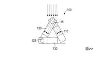
図21に、着磁された状態での磁性マーカ内の磁界の様子を示す。図22は、第1ロッド、第2ロッド、第3ロッドが三角形に配置された状態(第1ロッドの長手方向の他端と第3ロッドの長手方向の他端とを接触させた状態)での磁界の様子を示す図である。磁性マーカセット10によれば、磁性マーカ100が針200から押し出され、第1ロッド110の長手方向の端110aと第3ロッド130の長手方向の端130bとが接触する。このように変形した場合、第1ロッド110、第2ロッド120、第3ロッド130で三角形を形成することになる。針200に挿入されているときには第1接続部115において磁界の方向が逆転するように着磁しているので、針200から押し出されて変形したときには、第1接続部115の磁界の方向はほぼ同じ方向になる。よって、磁性マーカ100によって生じる磁界が強くなるので検出が容易になる。図23は、特許文献2に示した磁性マーカを検出する装置を用いて図22の上側から磁束密度を観測した結果を示している。横軸は、磁性マーカを検出する装置のプローブヘッドから磁性マーカまでの距離、縦軸は磁束密度を示している。図22のように着磁されている場合、プローブからの距離が離れても磁束を検知しやすいことが分かる。Figure 21 shows the state of the magnetic field inside the magnetic marker in a magnetized state. Figure 22 shows the state of the magnetic field when the first rod, second rod, and third rod are arranged in a triangle (the other end of the first rod in the longitudinal direction is in contact with the other end of the third rod in the longitudinal direction). With the magnetic marker set 10, the
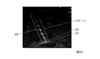
なお、針200の表面には、あらかじめ定めたパターンで超音波の反射特性が変化する加工を施せばよい。図24は、超音波の反射特性が変化するパターンを施した針を対象物に刺し、超音波で検知している様子を示している。針200の先端221,222とパターンが検出できていることが分かる。このように、針に超音波の反射特性が変化するパターンを施せば、磁性マーカ100を配置する位置を認識しやすい。同様に、磁性マーカ100に、あらかじめ定めたパターンで超音波の反射特性が変化する加工を施してもよい。例えば、第1ロッド110、第2ロッド120、第3ロッド130で異なるパターンを施せば、磁性マーカ100を配置した際に、磁性マーカ100の配置の状態を認識できる。針200と磁性マーカ100の両方に、あらかじめ定めたパターンで超音波の反射特性が変化する加工を施してもよいし、一方にのみ加工を施してもよい。The surface of the
<磁性マーカ配置方法>
図25に磁性マーカ配置方法の処理フローを示す。点線で示したステップは、不要な場合もあるステップである。磁性マーカ100は、あらかじめ着磁しておいてもよいし、使用者自身が着磁させた後に使用してもよい。着磁していない磁性マーカ100が針200に挿入されている場合は、使用者は、永久磁石300を図17もしくは図20のように配置し、磁性マーカ100に着磁させる(S10:着磁ステップ)。図17のように、永久磁石300も含んだ磁性マーカセット10を流通させてもよい。この場合は、使用者は永久磁石300から針200を取り外す(S20:針取り出しステップ)。永久磁石300を含まない着磁済の磁性マーカセット10を流通させてもよい。使用者は、磁性マーカ100が穴210に挿入された針200を、針200の先端221が磁性マーカ100を配置したい位置になるように対象物に刺す(S30:針挿入ステップ)。例えば、使用者は、針200を、先端221が乳がんの位置になるように乳房に刺す。その後、第1接続部115が磁性マーカ100を探知する装置の方向に向くように穴210から磁性マーカ100を押し出す(S40:押し出しステップ)。例えば、磁性マーカ100を乳房内に配置するのであれば、第1接続部115が乳房の外側に向くように磁性マーカ100を押し出せばよい。なお、針挿入ステップ(S30)で、押し出した第1接続部115が乳房の外側に向くように針を刺しておくことで、押し出しステップ(S40)では第1接続部115の向きを意識する必要がない状態にしてもよい。そして、接近機構140として糸143を利用している場合は、糸143を切断する(S50:切断ステップ)。<Magnetic marker placement method>
FIG. 25 shows the process flow of the magnetic marker arrangement method. The steps shown by dotted lines are steps that may not be necessary. The
10 磁性マーカセット 100 磁性マーカ
110 第1ロッド 115 第1接続部
120 第2ロッド 125 第2接続部
130 第3ロッド 135 弾性体
140 接近機構 141 固定部
142 保持部 143 糸
200 針 210 穴
221,222 先端 300 永久磁石
310 スリット 400 収納手段
500 操作部 510 押し出し手段
520 内筒 521 内筒側面穴
530 内々筒 531 内々筒側面穴
550 切断手段 560 スリット
570 つまみ 580 端部10 Magnetic marker set 100
Claims (10)
Translated fromJapanese前記磁性マーカは、
前記第1ロッドの長手方向の一端と前記第2ロッドの長手方向の一端とが回転自在に接続された第1接続部と、
前記第2ロッドの長手方向の他端と前記第3ロッドの長手方向の一端とが回転自在に接続された第2接続部も
有し、
前記磁性マーカは、前記穴に挿入され、前記第1接続部において磁界の方向が逆転するように着磁されており、
前記磁性マーカセットは、
前記磁性マーカが前記穴から押し出されたときに前記第1ロッドの長手方向の他端と前記第3ロッドの長手方向の他端とを接近させる接近機構も備える
ことを特徴とする磁性マーカセット。 A magnetic marker set including a first rod, a second rod, and a rod-shaped third rod, each of which is made of a magnetic material having a rod-shaped residual magnetization characteristic, and a needle having a hole in the longitudinal direction,
The magnetic marker is
a first connection portion at which one end of the first rod in a longitudinal direction and one end of the second rod in a longitudinal direction are rotatably connected;
a second connection portion at which the other end of the second rod in the longitudinal direction and one end of the third rod in the longitudinal direction are rotatably connected;
the magnetic marker is inserted into the hole and magnetized such that a direction of a magnetic field is reversed at the first connection portion;
The magnetic marker set includes:
A magnetic marker set further comprising an approaching mechanism for bringing the other longitudinal end of the first rod and the other longitudinal end of the third rod closer together when the magnetic marker is pushed out of the hole.
前記第1接続部と前記第2接続部は、コイル状の弾性体で構成されている
ことを特徴とする磁性マーカセット。 2. The magnetic marker set according to claim 1,
A magnetic marker set, characterized in that the first connection portion and the second connection portion are composed of a coil-shaped elastic body.
前記接近機構は、前記穴内に配置された糸を有し、
前記磁性マーカは、前記第1ロッド、前記第2ロッド、前記第3ロッドの順番で前記穴から押し出されるように配置されており、前記糸の一端は前記第1ロッドの長手方向の他端に固定され、前記糸は前記第3ロッドの長手方向の他端に移動自由に保持されている
ことを特徴とする磁性マーカセット。 3. The magnetic marker set according to claim 1 or 2,
the approximation mechanism includes a thread disposed within the hole;
A magnetic marker set characterized in that the magnetic markers are arranged so as to be pushed out of the holes in the order of the first rod, the second rod, and the third rod, one end of the thread is fixed to the other longitudinal end of the first rod, and the thread is held freely movable at the other longitudinal end of the third rod.
前記糸を切断する切断手段も備える
ことを特徴とする磁性マーカセット。 4. The magnetic marker set according to claim 3,
The magnetic marker set further comprises a cutting means for cutting the thread.
前記穴内に配置された内筒と、前記内筒内に配置された内々筒も有し、
前記切断手段は、前記内筒の側面に形成された内筒側面穴と、前記内々筒の側面に形成された内々筒側面穴で構成され、
前記内筒側面穴と前記内々筒側面穴とが対向する位置に配置されている状態で、前記糸は前記内筒側面穴と前記内々筒側面穴を通っており、
前記内筒側面穴と前記内々筒側面穴とが対向しない位置にすることで、前記糸を切断する
ことを特徴とする磁性マーカセット。 5. The magnetic marker set according to claim 4,
an inner cylinder disposed within the bore; and an inner cylinder disposed within the inner cylinder;
The cutting means is composed of an inner cylinder side hole formed on a side surface of the inner cylinder and an inner cylinder side hole formed on a side surface of the inner cylinder,
the inner cylinder side hole and the inner cylinder side hole are disposed in opposing positions, and the thread passes through the inner cylinder side hole and the inner cylinder side hole;
A magnetic marker set, characterized in that the thread is cut by positioning the inner cylinder side hole and the inner cylinder side hole so that they do not face each other.
前記針及び前記磁性マーカ、もしくは前記針と前記磁性マーカの一方には、あらかじめ定めたパターンで超音波の反射特性が変化するように加工が施されている
ことを特徴とする磁性マーカセット。 A magnetic marker set according to any one of claims 1 to 5,
A magnetic marker set, characterized in that either the needle or the magnetic marker, or one of the needle and the magnetic marker, is processed so that its ultrasonic reflection characteristics change in a predetermined pattern.
一方の面がN極、他方の面がS極の板であり、一方の面から他方の面に貫通したスリットを有する永久磁石と、
前記第1接続部の位置に前記永久磁石のいずれかの面が一致するように、前記磁性マーカが挿入された前記針を前記スリットに挿入した状態で保持する収納手段も
備える
ことを特徴とする磁性マーカセット。 A magnetic marker set according to any one of claims 1 to 6,
A permanent magnet having a plate with a north pole on one side and a south pole on the other side, and a slit penetrating from one side to the other side;
A magnetic marker set further comprising a storage means for holding the needle with the magnetic marker inserted in the slit so that one of the faces of the permanent magnet coincides with the position of the first connection portion.
一方の面がN極、他方の面がS極の板状の永久磁石と、
前記第1接続部の位置が前記永久磁石のいずれかの面と同一の面上であり、かつ前記面の法線方向と前記第2ロッドの長手方向が一致するように、前記磁性マーカが挿入された前記針を配置した状態で保持する収納手段も
備える
ことを特徴とする磁性マーカセット。 A magnetic marker set according to any one of claims 1 to 6,
A plate-shaped permanent magnet with a north pole on one side and a south pole on the other side,
The magnetic marker set also comprises a storage means for holding the needle with the magnetic marker inserted in an positioned state so that the position of the first connection portion is on the same plane as one of the faces of the permanent magnet and the normal direction of the face coincides with the longitudinal direction of the second rod.
前記永久磁石の厚さは、前記第2ロッドの長さの1/2以上であり、
前記針は、前記第2ロッドが前記永久磁石の位置になるように保持されている
ことを特徴とする磁性マーカセット。 The magnetic marker set according to claim 7 or 8,
The thickness of the permanent magnet is equal to or greater than half the length of the second rod,
A magnetic marker set, wherein the needle is held so that the second rod is at the position of the permanent magnet.
前記磁性マーカを前記針から押し出す押し出し手段も備える
ことを特徴とする磁性マーカセット。 A magnetic marker set according to any one of claims 1 to 9,
The magnetic marker set further comprises an extrusion means for extruding the magnetic marker from the needle.
Applications Claiming Priority (1)
| Application Number | Priority Date | Filing Date | Title |
|---|---|---|---|
| PCT/JP2021/028332WO2023007702A1 (en) | 2021-07-30 | 2021-07-30 | Magnetic marker set and method for arranging magnetic marker |
Publications (3)
| Publication Number | Publication Date |
|---|---|
| JPWO2023007702A1 JPWO2023007702A1 (en) | 2023-02-02 |
| JPWO2023007702A5 JPWO2023007702A5 (en) | 2024-02-05 |
| JP7541784B2true JP7541784B2 (en) | 2024-08-29 |
Family
ID=85086641
Family Applications (1)
| Application Number | Title | Priority Date | Filing Date |
|---|---|---|---|
| JP2023538165AActiveJP7541784B2 (en) | 2021-07-30 | 2021-07-30 | Magnetic Marker Set |
Country Status (4)
| Country | Link |
|---|---|
| US (1) | US12357417B2 (en) |
| JP (1) | JP7541784B2 (en) |
| CN (1) | CN117098495A (en) |
| WO (1) | WO2023007702A1 (en) |
Families Citing this family (1)
| Publication number | Priority date | Publication date | Assignee | Title |
|---|---|---|---|---|
| GB2582123B (en) | 2018-01-25 | 2021-04-28 | Endomagnetics Ltd | Systems and methods for detecting magnetic markers for surgical guidance |
Citations (6)
| Publication number | Priority date | Publication date | Assignee | Title |
|---|---|---|---|---|
| US20080269601A1 (en) | 2007-04-26 | 2008-10-30 | Schwamb John P | Fiducial marker with rings |
| JP2012531276A (en) | 2009-06-26 | 2012-12-10 | シアナ メディカル,インク. | Apparatus, system and method for positioning a marker or tissue structure in a body |
| JP2017521223A (en) | 2014-07-23 | 2017-08-03 | ジーアイ ウィンドウズ, インコーポレイテッド | Magnetic anastomosis device and method of delivery |
| JP2018526160A (en) | 2015-06-04 | 2018-09-13 | エンドマグネティクス リミテッド | Marker material for magnetic marker localization (MML) |
| JP2019146957A (en) | 2018-01-25 | 2019-09-05 | エンドマグネティクス リミテッド | Systems and methods for detecting magnetic markers for surgical guidance |
| WO2021013831A1 (en) | 2019-07-24 | 2021-01-28 | Bip Biomed. Instrumente & Produkte Gmbh | Implantable marker |
Family Cites Families (5)
| Publication number | Priority date | Publication date | Assignee | Title |
|---|---|---|---|---|
| JP3960558B1 (en) | 2007-02-23 | 2007-08-15 | 株式会社共伸 | Magnetic fluid detector and detector |
| WO2009099767A2 (en)* | 2008-01-31 | 2009-08-13 | C.R. Bard, Inc. | Biopsy tissue marker |
| US9386942B2 (en)* | 2009-06-26 | 2016-07-12 | Cianna Medical, Inc. | Apparatus, systems, and methods for localizing markers or tissue structures within a body |
| GB2573500B (en)* | 2018-03-23 | 2020-11-04 | Endomagnetics Ltd | Magnetic markers for surgical guidance |
| US11166782B1 (en)* | 2020-07-19 | 2021-11-09 | Sirius Medical Systems B.V. | Implantable marker and a method of implanting markers |
- 2021
- 2021-07-30WOPCT/JP2021/028332patent/WO2023007702A1/ennot_activeCeased
- 2021-07-30USUS18/285,531patent/US12357417B2/enactiveActive
- 2021-07-30CNCN202180096073.3Apatent/CN117098495A/enactivePending
- 2021-07-30JPJP2023538165Apatent/JP7541784B2/enactiveActive
Patent Citations (6)
| Publication number | Priority date | Publication date | Assignee | Title |
|---|---|---|---|---|
| US20080269601A1 (en) | 2007-04-26 | 2008-10-30 | Schwamb John P | Fiducial marker with rings |
| JP2012531276A (en) | 2009-06-26 | 2012-12-10 | シアナ メディカル,インク. | Apparatus, system and method for positioning a marker or tissue structure in a body |
| JP2017521223A (en) | 2014-07-23 | 2017-08-03 | ジーアイ ウィンドウズ, インコーポレイテッド | Magnetic anastomosis device and method of delivery |
| JP2018526160A (en) | 2015-06-04 | 2018-09-13 | エンドマグネティクス リミテッド | Marker material for magnetic marker localization (MML) |
| JP2019146957A (en) | 2018-01-25 | 2019-09-05 | エンドマグネティクス リミテッド | Systems and methods for detecting magnetic markers for surgical guidance |
| WO2021013831A1 (en) | 2019-07-24 | 2021-01-28 | Bip Biomed. Instrumente & Produkte Gmbh | Implantable marker |
Also Published As
| Publication number | Publication date |
|---|---|
| CN117098495A (en) | 2023-11-21 |
| US12357417B2 (en) | 2025-07-15 |
| US20240180440A1 (en) | 2024-06-06 |
| JPWO2023007702A1 (en) | 2023-02-02 |
| WO2023007702A1 (en) | 2023-02-02 |
Similar Documents
| Publication | Publication Date | Title |
|---|---|---|
| US6919787B1 (en) | Method and apparatus for magnetic coupling | |
| JP7541784B2 (en) | Magnetic Marker Set | |
| AU2016272550B2 (en) | Marker materials and forms for magnetic marker localization (MML) | |
| US4827622A (en) | Tape measure | |
| JP3822062B2 (en) | Magnetic connection structure | |
| WO1984003854A1 (en) | Robot having magnetic proximity sensor | |
| EP1193778A3 (en) | Magnetization reversal methods for magnetic film, magnetoresistive films, and magnetic memories using them | |
| JPS60236639A (en) | Intra-uterus apparatus detection and removal system | |
| JP2023542864A (en) | Improved magnetic trajectory prediction and localization | |
| JP2011133383A (en) | Device for measuring two-dimensional vector magnetism | |
| US7883130B2 (en) | Surgical magnetic retrieval tool | |
| TWI533968B (en) | Magnetic attractive conjunction mechanism of rotating gripper in clamping device | |
| US4065739A (en) | Reversible direction solenoid assembly | |
| JPWO2023007702A5 (en) | ||
| JP6771901B2 (en) | Magnetizing device and manufacturing method for magnetic linear encoder | |
| JP2016175738A (en) | Pair of article holding devices, article delivery method, and article inspection device | |
| JP5490497B2 (en) | measuring device | |
| CN107091997B (en) | conical magnet | |
| CN206862329U (en) | Contourgraph measurement head with Overload Protection performance | |
| JP2579258B2 (en) | Parts supply control device | |
| CN215503593U (en) | Check Nail and Check Nail Wrench | |
| JP6681145B2 (en) | How to pick up goods | |
| JP2024151019A (en) | Electromagnets and magnetic field application systems | |
| JP2025000537A (en) | Detection device | |
| CN100399040C (en) | A magnetic probe magnetizer for a magnetic force microscope |
Legal Events
| Date | Code | Title | Description |
|---|---|---|---|
| A521 | Request for written amendment filed | Free format text:JAPANESE INTERMEDIATE CODE: A523 Effective date:20231027 | |
| A621 | Written request for application examination | Free format text:JAPANESE INTERMEDIATE CODE: A621 Effective date:20231027 | |
| A521 | Request for written amendment filed | Free format text:JAPANESE INTERMEDIATE CODE: A523 Effective date:20231031 | |
| A131 | Notification of reasons for refusal | Free format text:JAPANESE INTERMEDIATE CODE: A131 Effective date:20240618 | |
| A521 | Request for written amendment filed | Free format text:JAPANESE INTERMEDIATE CODE: A523 Effective date:20240709 | |
| TRDD | Decision of grant or rejection written | ||
| A01 | Written decision to grant a patent or to grant a registration (utility model) | Free format text:JAPANESE INTERMEDIATE CODE: A01 Effective date:20240723 | |
| A61 | First payment of annual fees (during grant procedure) | Free format text:JAPANESE INTERMEDIATE CODE: A61 Effective date:20240809 | |
| R150 | Certificate of patent or registration of utility model | Ref document number:7541784 Country of ref document:JP Free format text:JAPANESE INTERMEDIATE CODE: R150 |