JP7541129B2 - Image prediction for HDR imaging in an open loop codec - Patents.com - Google Patents
Image prediction for HDR imaging in an open loop codec - Patents.comDownload PDFInfo
- Publication number
- JP7541129B2 JP7541129B2JP2022579948AJP2022579948AJP7541129B2JP 7541129 B2JP7541129 B2JP 7541129B2JP 2022579948 AJP2022579948 AJP 2022579948AJP 2022579948 AJP2022579948 AJP 2022579948AJP 7541129 B2JP7541129 B2JP 7541129B2
- Authority
- JP
- Japan
- Prior art keywords
- input image
- data set
- input
- noise
- image
- Prior art date
- Legal status (The legal status is an assumption and is not a legal conclusion. Google has not performed a legal analysis and makes no representation as to the accuracy of the status listed.)
- Active
Links
Images


Classifications
- H—ELECTRICITY
- H04—ELECTRIC COMMUNICATION TECHNIQUE
- H04N—PICTORIAL COMMUNICATION, e.g. TELEVISION
- H04N19/00—Methods or arrangements for coding, decoding, compressing or decompressing digital video signals
- H04N19/85—Methods or arrangements for coding, decoding, compressing or decompressing digital video signals using pre-processing or post-processing specially adapted for video compression
- H—ELECTRICITY
- H04—ELECTRIC COMMUNICATION TECHNIQUE
- H04N—PICTORIAL COMMUNICATION, e.g. TELEVISION
- H04N19/00—Methods or arrangements for coding, decoding, compressing or decompressing digital video signals
- H04N19/10—Methods or arrangements for coding, decoding, compressing or decompressing digital video signals using adaptive coding
- H04N19/102—Methods or arrangements for coding, decoding, compressing or decompressing digital video signals using adaptive coding characterised by the element, parameter or selection affected or controlled by the adaptive coding
- H04N19/117—Filters, e.g. for pre-processing or post-processing
- H—ELECTRICITY
- H04—ELECTRIC COMMUNICATION TECHNIQUE
- H04N—PICTORIAL COMMUNICATION, e.g. TELEVISION
- H04N19/00—Methods or arrangements for coding, decoding, compressing or decompressing digital video signals
- H04N19/10—Methods or arrangements for coding, decoding, compressing or decompressing digital video signals using adaptive coding
- H04N19/134—Methods or arrangements for coding, decoding, compressing or decompressing digital video signals using adaptive coding characterised by the element, parameter or criterion affecting or controlling the adaptive coding
- H04N19/136—Incoming video signal characteristics or properties
- H—ELECTRICITY
- H04—ELECTRIC COMMUNICATION TECHNIQUE
- H04N—PICTORIAL COMMUNICATION, e.g. TELEVISION
- H04N19/00—Methods or arrangements for coding, decoding, compressing or decompressing digital video signals
- H04N19/10—Methods or arrangements for coding, decoding, compressing or decompressing digital video signals using adaptive coding
- H04N19/134—Methods or arrangements for coding, decoding, compressing or decompressing digital video signals using adaptive coding characterised by the element, parameter or criterion affecting or controlling the adaptive coding
- H04N19/146—Data rate or code amount at the encoder output
- H—ELECTRICITY
- H04—ELECTRIC COMMUNICATION TECHNIQUE
- H04N—PICTORIAL COMMUNICATION, e.g. TELEVISION
- H04N19/00—Methods or arrangements for coding, decoding, compressing or decompressing digital video signals
- H04N19/10—Methods or arrangements for coding, decoding, compressing or decompressing digital video signals using adaptive coding
- H04N19/169—Methods or arrangements for coding, decoding, compressing or decompressing digital video signals using adaptive coding characterised by the coding unit, i.e. the structural portion or semantic portion of the video signal being the object or the subject of the adaptive coding
- H04N19/17—Methods or arrangements for coding, decoding, compressing or decompressing digital video signals using adaptive coding characterised by the coding unit, i.e. the structural portion or semantic portion of the video signal being the object or the subject of the adaptive coding the unit being an image region, e.g. an object
- H04N19/172—Methods or arrangements for coding, decoding, compressing or decompressing digital video signals using adaptive coding characterised by the coding unit, i.e. the structural portion or semantic portion of the video signal being the object or the subject of the adaptive coding the unit being an image region, e.g. an object the region being a picture, frame or field
- H—ELECTRICITY
- H04—ELECTRIC COMMUNICATION TECHNIQUE
- H04N—PICTORIAL COMMUNICATION, e.g. TELEVISION
- H04N19/00—Methods or arrangements for coding, decoding, compressing or decompressing digital video signals
- H04N19/10—Methods or arrangements for coding, decoding, compressing or decompressing digital video signals using adaptive coding
- H04N19/169—Methods or arrangements for coding, decoding, compressing or decompressing digital video signals using adaptive coding characterised by the coding unit, i.e. the structural portion or semantic portion of the video signal being the object or the subject of the adaptive coding
- H04N19/182—Methods or arrangements for coding, decoding, compressing or decompressing digital video signals using adaptive coding characterised by the coding unit, i.e. the structural portion or semantic portion of the video signal being the object or the subject of the adaptive coding the unit being a pixel
- H—ELECTRICITY
- H04—ELECTRIC COMMUNICATION TECHNIQUE
- H04N—PICTORIAL COMMUNICATION, e.g. TELEVISION
- H04N19/00—Methods or arrangements for coding, decoding, compressing or decompressing digital video signals
- H04N19/10—Methods or arrangements for coding, decoding, compressing or decompressing digital video signals using adaptive coding
- H04N19/169—Methods or arrangements for coding, decoding, compressing or decompressing digital video signals using adaptive coding characterised by the coding unit, i.e. the structural portion or semantic portion of the video signal being the object or the subject of the adaptive coding
- H04N19/186—Methods or arrangements for coding, decoding, compressing or decompressing digital video signals using adaptive coding characterised by the coding unit, i.e. the structural portion or semantic portion of the video signal being the object or the subject of the adaptive coding the unit being a colour or a chrominance component
- H—ELECTRICITY
- H04—ELECTRIC COMMUNICATION TECHNIQUE
- H04N—PICTORIAL COMMUNICATION, e.g. TELEVISION
- H04N19/00—Methods or arrangements for coding, decoding, compressing or decompressing digital video signals
- H04N19/50—Methods or arrangements for coding, decoding, compressing or decompressing digital video signals using predictive coding
- H04N19/597—Methods or arrangements for coding, decoding, compressing or decompressing digital video signals using predictive coding specially adapted for multi-view video sequence encoding
Landscapes
- Engineering & Computer Science (AREA)
- Multimedia (AREA)
- Signal Processing (AREA)
- Compression Or Coding Systems Of Tv Signals (AREA)
- Image Processing (AREA)
Description
Translated fromJapanese [0001] 関連出願の相互参照
本願は、欧州特許出願第20182014.9号及び米国仮出願第63/043,198号に対する優先権を主張しており、両出願は2020年6月24日付で出願されており、それぞれ本件に全体的に援用されている。 [0001] CROSS-REFERENCE TO RELATED APPLICATIONS This application claims priority to European Patent Application No. 20182014.9 and U.S. Provisional Application No. 63/043,198, both of which were filed on June 24, 2020, and each of which is incorporated herein by reference in its entirety.
[0002] 技術分野
本発明は概して画像に関連する。より詳細には、本発明の実施形態は、オープン・ループ・コーデックにおける高ダイナミック・レンジ(high dynamic range,HDR)イメージングのための画像予測に関連する。 TECHNICAL FIELD The present invention relates generally to images. More particularly, embodiments of the present invention relate to image prediction for high dynamic range (HDR) imaging in open loop codecs.
[0003] 本件で使用されているように、用語「ダイナミック・レンジ」(dynamic range,DR)は、例えば、最も暗いグレー(ブラック)から最も明るいホワイト(ハイライト)までのような、画像内の強度のレンジ(例えば、輝度、ルマ)を知覚する人間の視覚系(human visual system,HVS)の能力に関連している可能性がある。この意味で、DRは「シーン参照」(scene-referred)強度に関連している。また、DRは、特定の幅の強度レンジを適切に又は近似的にレンダリングするディスプレイ・デバイスの能力にも関連する可能性もある。この意味で、DRは「ディスプレイ参照」(display-referred)強度に関連している。本件の記載の何らかの箇所で、特定の意味を有するように特定の意味が明示的に指定されていない限り、この用語は、何れの意味にも、即ち可換に使用されてもよいことが推察されるべきである。[0003] As used herein, the term "dynamic range" (DR) may relate to the ability of the human visual system (HVS) to perceive a range of intensities (e.g., luminance, luma) in an image, such as from darkest gray (black) to brightest white (highlight). In this sense, DR relates to "scene-referred" intensity. DR may also relate to the ability of a display device to properly or approximately render a particular width of intensity range. In this sense, DR relates to "display-referred" intensity. Unless a particular meaning is explicitly specified anywhere in this description to have a particular meaning, it should be inferred that the terms may be used in either sense, i.e., interchangeably.
[0004] 本件で使用されるように、用語「高ダイナミック・レンジ(HDR)」は、人間の視覚系(HVS)の大きさの14~15桁に及ぶDR幅に関連する。実際には、人間が強度レンジにおいて幅広い範囲を同時に知覚できるDRは、HDRとの関係で幾らか打ち切られる可能性がある。[0004] As used herein, the term "high dynamic range (HDR)" refers to a DR width that spans 14-15 orders of magnitude of the human visual system (HVS). In practice, the DR that humans can simultaneously perceive in a wide range of intensity ranges may be somewhat truncated in relation to HDR.
[0005] 実際には、画像は、1つ以上のカラー成分(例えば、ルマYとクロマCb及びCr)を含み、各カラー成分は、画素当たりのnビットの精度によって表される(例えば、n=8)。線形又はガンマ輝度コーディングを使用する場合、n≦8の画像(例えば、カラー24ビットJPEG画像)が標準ダイナミック・レンジの画像と考えられ、n>8の画像は強調された又は高いダイナミック・レンジの画像と考えられてもよい。HDR画像は、インダストリアル・ライト&マジック社により開発されたOpenEXRファイル・フォーマットのような高精度の(例えば、16ビット)浮動小数点フォーマットを使用して、保存及び配信されることも可能である。[0005] In practice, images include one or more color components (e.g., luma Y and chroma Cb and Cr), each represented with n bits of precision per pixel (e.g., n=8). When using linear or gamma luminance coding, images with n≦8 (e.g., color 24-bit JPEG images) may be considered standard dynamic range images, and images with n>8 may be considered enhanced or high dynamic range images. HDR images may also be stored and distributed using high precision (e.g., 16-bit) floating-point formats, such as the OpenEXR file format developed by Industrial Light & Magic, Inc.
[0006] 現在、ほとんどの消費者向けデスクトップ・ディスプレイは、200ないし300 cd/m2又はニット(nits)の輝度をサポートしている。ほとんどの消費者向けHDTVは、300ないし500 nitの範囲に及び、新たなモデルは1000 nits(cd/m2)に達している。このように、このような従来のディスプレイは、HDRに関連して、標準ダイナミック・レンジ(standard dynamic range,SDR)とも呼ばれる、より低いダイナミック・レンジを表している。キャプチャ装置(例えば、カメラ)及びHDRディスプレイ(例えば、ドルビー・ラボラトリーズからのPRM-4200プロフェッショナル・リファレンス・モニター)の双方の進歩に起因して、HDRコンテンツの利用可能性が増大するにつれて、HDRコンテンツは、より高いダイナミック・レンジ(例えば、1,000 nitsないし5,000 nits以上)をサポートするHDRディスプレイにおいて、カラー・グレーディングされて表示される可能性がある。 [0006] Currently, most consumer desktop displays support a luminance of 200 to300 cd/m2 or nits. Most consumer HDTVs range from 300 to 500 nits, with newer models reaching 1000 nits (cd/m2 ). As such, such conventional displays represent a lower dynamic range, also referred to as standard dynamic range (SDR), in the context of HDR. As the availability of HDR content increases due to advances in both capture devices (e.g., cameras) and HDR displays (e.g., the PRM-4200 Professional Reference Monitor from Dolby Laboratories), HDR content may be color graded and displayed on HDR displays that support a higher dynamic range (e.g., 1,000 nits to 5,000 nits or more).
[0007] 本件で使用されるように、「リシェイピング(reshaping)」又は「リマッピング(remapping)」という用語は、デジタル画像の元のビット深度及び元のコードワードの分布又は表現(例えば、ガンマ、PQ、又はHLGなど)から、同じ又は異なるビット深度及び異なるコードワードの分布又は表現の画像への、サンプル_対_サンプルの又はコードワード_対_コードワードのマッピングのプロセスを意味する。リシェイピングは、固定されたビット・レートでの改善された圧縮性又は改善された画像品質を可能にする。例えば、限定ではないが、フォワード・リシェイピングを、10ビット又は12ビットのPQコーディングされたHDRビデオに適用して、10ビット・ビデオ・コーディング・アーキテクチャにおけるコーディング効率を改善してもよい。受信機において、受信信号を解凍した後(受信信号はリシェイプされていてもされていなくてもよい)、受信機は、その信号を元のコードワード分布に復元し、及び/又は、より高いダイナミック・レンジを達成するために、インバース(又は、バックワード)リシェイピング機能を適用することができる。[0007] As used herein, the term "reshaping" or "remapping" refers to the process of mapping sample-to-sample or codeword-to-codeword from an original bit-depth and original codeword distribution or representation (e.g., gamma, PQ, or HLG) of a digital image to an image of the same or different bit-depth and different codeword distribution or representation. Reshaping allows for improved compressibility or improved image quality at a fixed bit rate. For example, but not by way of limitation, forward reshaping may be applied to 10-bit or 12-bit PQ coded HDR video to improve coding efficiency in 10-bit video coding architectures. At the receiver, after decompressing the received signal (which may or may not have been reshaped), the receiver may apply an inverse (or backward) reshaping function to restore the signal to the original codeword distribution and/or achieve a higher dynamic range.
[0008] HDRコーディングにおいて、画像予測(又はリシェイピング)は、ベースライン標準ダイナミック・レンジ(SDR)画像と、バックワード・リシェイピング機能を表現する予測係数のセットとを用いて、HDR画像が再構成されることを可能にする。レガシー・デバイスは、単に、SDR画像を復号化するに過ぎないかもしれないが;HDRディスプレイは、バックワード・リシェイピング機能をSDR画像に適用することによって、HDR画像を再構成することが可能である。ビデオ・コーディングにおいて、このような画像予測は、後方互換性を維持しつつコーディング効率を改善するために使用されることが可能である。このようなシステムは、「クローズド・ループ(closed loop)」と呼ばれるものであるか(その場合、エンコーダは復号化経路を含み、予測係数は、元の及び復号化されたSDR及びHDRデータの両方に基づいて導出される)、又は、「オープン・ループ(open loop)」と呼ばれるものであってもよい(その場合、このような復号化ループは存在せず、予測係数は元のデータのペアのみに基づいて導出される)。本件の発明者らによって認識されているように、オープン・ループ・コーデックの効率的な画像予測のための改良された技術が望まれている。[0008] In HDR coding, image prediction (or reshaping) allows an HDR image to be reconstructed using a baseline standard dynamic range (SDR) image and a set of prediction coefficients that represent a backward reshaping function. A legacy device may simply decode an SDR image; however, an HDR display may reconstruct an HDR image by applying a backward reshaping function to the SDR image. In video coding, such image prediction can be used to improve coding efficiency while maintaining backward compatibility. Such systems may be called "closed loop" (where the encoder includes a decoding path and prediction coefficients are derived based on both the original and decoded SDR and HDR data) or "open loop" (where no such decoding loop exists and prediction coefficients are derived based only on the original data pair). As recognized by the present inventors, improved techniques for efficient image prediction in open loop codecs are desired.
[0009] このセクションで説明されるアプローチは、追求される可能性のあるアプローチであるが、必ずしも以前に考案されていたり又は追求されていたりするアプローチであるとは限らないはない。従って、別段の指定がない限り、本セクションに記載されている如何なるアプローチも、単に本セクションに含まれているという理由だけで先行技術としての適格であると仮定されるべきではない。同様に、1以上のアプローチに関して特定される事項は、別段の指定がない限り、本セクションに基づいて何らかの先行技術で認識されていると仮定すべきではない。[0009] The approaches described in this section are approaches that could be pursued, but not necessarily approaches that have been previously conceived or pursued. Thus, unless otherwise specified, it should not be assumed that any approach described in this section qualifies as prior art merely by virtue of its inclusion in this section. Similarly, it should not be assumed that matter identified with one or more approaches is recognized by this section as any prior art, unless otherwise specified.
[0010] 本発明の実施形態は、添付図面における図面において、限定ではない例示として説明されており、図中、同様な参照番号は同様な要素を参照している。
[0017] オープン・ループ・コーデックにおける画像の効率的なコーディングのための画像予測技術が本件で説明される。以下の説明では、説明の目的で、本発明の十分な理解をもたらすように、多くの具体的な詳細が説明されている。しかしながら、本発明は、これらの具体的な詳細によらず実施されてもよいことは明らかであろう。他の例では、本発明を不必要に隠したり、不明瞭にしたり、又は曖昧にしたりしてしまうことを避けるために、周知の構造やデバイスは、審らかに詳細には説明されていない。[0017] Image prediction techniques for efficient coding of images in an open loop codec are described herein. In the following description, for purposes of explanation, numerous specific details are set forth in order to provide a thorough understanding of the present invention. It will be apparent, however, that the present invention may be practiced without these specific details. In other instances, well-known structures and devices have not been described in apparent detail in order to avoid unnecessarily obscuring, obscuring, or obscuring the present invention.
[0018] 概要
本件で説明される例示的な実施形態は、画像予測技術に関連する。実施形態では、1つ以上のプロセッサを含む装置において、プロセッサは、同一のシーンを表す高ダイナミック・レンジ(HDR)及び標準ダイナミック・レンジ(SDR)における入力されたペアの参照画像を受け取る。プロセッサは:
HDR画像の特徴に少なくとも基づいて、ノイズ強度を有するノイズ・データを生成し;
ノイズ・データをSDR画像に加えることによって、ノイズ入力データ・セットを生成し;
HDR画像に基づいて、第1の拡張入力データ・セットを生成し;
SDR画像とノイズ入力データ・セットとを結合して、第2の拡張入力データ・セットを生成し;
第2の拡張入力データ・セットに基づいて第1の拡張入力データ・セットを予測する予測モデルを生成し;
予測モデル・パラメータのセットを生成するために、最小誤差基準に従って予測モデルの解を求めるステップ;
第2の入力画像を圧縮して、圧縮されたビットストリームを生成し;及び
圧縮されたビットストリームと予測モデル・パラメータとを含む出力ビットストリームを生成する。 [0018] SUMMARY [0018] Exemplary embodiments described herein relate to image prediction techniques. In an embodiment, in an apparatus including one or more processors, the processor receives an input pair of reference images in high dynamic range (HDR) and standard dynamic range (SDR) representing the same scene. The processor:
generating noise data having a noise intensity based at least on the characteristics of the HDR image;
generating a noise input data set by adding noise data to the SDR image;
Generate a first augmented input data set based on the HDR image;
combining the SDR image and the noise input data set to generate a second augmented input data set;
generating a predictive model for predicting the first augmented input data set based on the second augmented input data set;
solving the predictive model according to a minimum error criterion to generate a set of predictive model parameters;
compressing the second input image to generate a compressed bitstream; and generating an output bitstream comprising the compressed bitstream and the prediction model parameters.
[0019] 例示的なHDRコーディング・システム
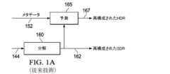
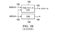
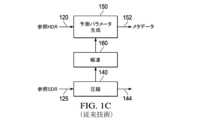
図1Aは、画像予測を使用する例示的なシングル・レイヤ・デコーダ・アーキテクチャを示しており、これは、下流のビデオ・デコーダにおける1つ以上の演算プロセッサで実装される可能性がある。図1Bは、例示的な「オープン・ループ」エンコーダ・アーキテクチャを示しており、これは、1つ以上の上流のビデオ・エンコーダにおける1つ以上の演算プロセッサで実装される可能性がある。図1Cは、例示的な「クローズド・ループ」エンコーダ・アーキテクチャを示す。 [0019] Exemplary HDR Coding Systems Figure 1A shows an exemplary single-layer decoder architecture using image prediction, which may be implemented in one or more computation processors in a downstream video decoder. Figure 1B shows an exemplary "open-loop" encoder architecture, which may be implemented in one or more computation processors in one or more upstream video encoders. Figure 1C shows an exemplary "closed-loop" encoder architecture.
[0020] このフレーム・ワークの下では、所与の参照HDRコンテンツ(120)の下で、対応するSDRコンテンツ(125)(即ち、HDRコンテンツと同じ画像を表現するが、カラー・グレーディングされており、標準ダイナミック・レンジで表現されているコンテンツ)が、上流の符号化デバイスによって、コーディングされたビデオ信号(144)のシングル・レイヤで符号化され且つ伝送されており、上流の符号化デバイスは、エンコーダ側のコーデック・アーキテクチャを実現する。SDRコンテンツ(144)は、ビデオ信号のシングル・レイヤにおいて、下流の復号化デバイスによって受信されて復号化される。また、予測メタデータ(例えば、バックワード・リシェイピング・パラメータ)(152)も、SDRコンテンツとともにビデオ信号において符号化されて伝送され、その結果、HDRディスプレイ・デバイスは、SDRコンテンツ(144)と受信したメタデータ(152)とに基づいてHDRコンテンツを再構成することが可能である。[0020] In this framework, for a given reference HDR content (120), a corresponding SDR content (125) (i.e., content that represents the same image as the HDR content, but color graded and represented in standard dynamic range) is encoded and transmitted in a single layer of a coded video signal (144) by an upstream encoding device, which implements an encoder-side codec architecture. The SDR content (144) is received and decoded by a downstream decoding device in a single layer of the video signal. Predictive metadata (e.g., backward reshaping parameters) (152) are also encoded and transmitted in the video signal together with the SDR content, so that an HDR display device can reconstruct the HDR content based on the SDR content (144) and the received metadata (152).
[0021] 図1B及び図1Cにおいて、実施形態では、所与の入力HDRデータ(120)の下で、SDRデータ(125)は、トーン・マッピング、フォワード・リシェイピング、マニュアルによるもの(カラー・グレーディングの際におけるもの)又は当該技術分野で公知の技術の組み合わせにより、HDRデータから生成されることが可能である。別の実施形態では、所与の参照SDRデータ(125)の下で、HDRデータ(120)は、インバース・トーンマッピング、バックワード・リシェイピング、マニュアルによるもの(カラー・グレーディングの際におけるもの)、又は当技術分野で公知の技術の組み合わせにより、SDRデータから生成されることが可能である。圧縮ブロック140(例えば、AVC、HEVC、AV1などのような何らかの既知のビデオ・コーディング・アルゴリズムに従って実現されたエンコーダ)は、コーディングされたビットストリームのシングル・レイヤ144においてSDR画像(125)を圧縮/符号化する。[0021] In FIG. 1B and FIG. 1C, in an embodiment, given input HDR data (120), SDR data (125) can be generated from the HDR data by tone mapping, forward reshaping, manual (in color grading), or a combination of techniques known in the art. In another embodiment, given reference SDR data (125), HDR data (120) can be generated from the SDR data by inverse tone mapping, backward reshaping, manual (in color grading), or a combination of techniques known in the art. A compression block 140 (e.g., an encoder implemented according to any known video coding algorithm such as AVC, HEVC, AV1, etc.) compresses/encodes the SDR image (125) in a
[0022] ユニット150によって生成されるようなメタデータ(152)は、ビデオ信号144の一部として、例えば補足的なエンハンスメント情報(supplemental enhancement information,SEI)メッセージングとして多重化されてもよい。従って、メタデータ(152)は、エンコーダ側で利用可能な強力な演算リソース及びオフライン符号化フロー(コンテンツ適応多重パス、ルック・アヘッド演算、インバース・ルマ・マッピング、インバース・クロマ・マッピング、CDFベースのヒストグラム近似、及び/又は転送などを含むが、これらに限定されない)を利用するために、エンコーダ側で生成又は予め生成されることが可能である。[0022] Metadata (152) as generated by
[0023] 図1B及び図1Cのエンコーダ・アーキテクチャは、入力HDR画像(120)をビデオ信号のコーディングされた/圧縮されたHDR画像に直接的に符号化することを回避するために使用することが可能である:むしろ、ビデオ信号におけるメタデータ(152)を使用して、下流の復号化デバイスは、SDR画像(125)(ビデオ信号において符号化されているもの)を、参照HDR画像(120)と同一であるか又は近い/最適に近似している再構成されたHDR画像(167)に、再構成することを可能にすることができる。[0023] The encoder architecture of Figures 1B and 1C can be used to avoid directly encoding the input HDR image (120) into a coded/compressed HDR image of the video signal; rather, using metadata (152) in the video signal, a downstream decoding device can be enabled to reconstruct the SDR image (125) (as encoded in the video signal) into a reconstructed HDR image (167) that is identical or a close/optimal approximation to the reference HDR image (120).
[0024] 幾つかの実施態様において、図1Aに示されるように、圧縮されたSDR画像を有するビデオ・ビットストリーム(144)とエンコーダによって生成された予測パラメータを有するメタデータ(152)とは、コーデック・フレームワークのデコーダ側で入力として受信される。解凍ブロック160は、ビデオ信号のシングル・レイヤ(144における圧縮されたビデオ・データを、復号化されたSDR画像(162)に解凍/復号化/圧縮解除する。解凍160は、典型的には、圧縮の140の逆に対応する。復号化されたSDR画像(162)は、圧縮ブロック(140)及び解凍ブロック(160)における量子化誤差の影響を被ったSDR画像(125)と同じである可能性があり、これは、SDRディスプレイ・デバイスに対して最適化されることが可能である。復号化されたSDR画像(162)は、SDRディスプレイ・デバイスにおいてレンダリングされるべき出力SDRビデオ信号において(例えば、HDMI(登録商標)インターフェースを介して、ビデオ・リンク等を介して)出力されてもよい。[0024] In some embodiments, as shown in FIG. 1A, a video bitstream (144) having a compressed SDR image and metadata (152) having prediction parameters generated by an encoder are received as input at the decoder side of the codec framework. A
[0025] 更に、予測ブロック165(「コンポーザ(composer)」と言及される場合もある)は、入力ビットストリームからのメタデータ(152)を、解凍されたデータ(162)に適用して、再構成されたHDR画像(167)を生成する。幾つかの実施態様において、再構成された画像は、参照HDR画像(120)と同一であるか、又は近い/最適に近似している、制作時品質又は制作時品質に近いHDR画像を表す。再構成された画像(167)は、HDRディスプレイ・デバイスでレンダリングされることになる出力HDRビデオ信号において(例えば、HDMI(登録商標)インターフェースを介して、ビデオ・リンク等を介して)出力されてもよい。[0025] Additionally, a prediction block 165 (sometimes referred to as a "composer") applies metadata (152) from the input bitstream to the decompressed data (162) to generate a reconstructed HDR image (167). In some embodiments, the reconstructed image represents an as-produced or near-as-produced HDR image that is identical to or a close/optimal approximation of the reference HDR image (120). The reconstructed image (167) may be output in an output HDR video signal (e.g., via an HDMI interface, via a video link, etc.) to be rendered on an HDR display device.
[0026] 一部の実施形態では、HDR表示デバイスに特有の表示管理処理が、再構成された画像(167)に対して、HDR画像レンダリング処理の一部として実行されてもよく、HDR画像レンダリング処理は、バックワード・リシェイピングされた画像(167)をHDR表示デバイスにおいてレンダリングする。[0026] In some embodiments, display management operations specific to an HDR display device may be performed on the reconstructed image (167) as part of an HDR image rendering process, which renders the backward reshaped image (167) on the HDR display device.
[0027] 図1Bは、「オープン・ループ」符号化アーキテクチャを示し、ここで、メタデータ152は、入力HDR及びSDR画像のみを使用してユニット150によって生成される。図1Cは、追加の解凍ブロック(160)を含む「クローズド・ループ」符号化アーキテクチャを示す。クローズド・ループ設計は、追加のビデオ解凍ステップ160を使用しており、デコーダが行うことになる動作する方法を装っている。これは、予測パラメータを(例えば、ブロック150において)生成するために、データのよりいっそう遙かに正確な記述をもたらすが;それは、追加の復号化ステップを必要とする。これは、単一のビット・レート又はプロファイルでビットストリームを生成する場合には良好であるが、サーバーが、「ビット・レート・ラダー(bit-rate ladder)」と一般的に呼ばれる複数のビット・レートでストリームを生成する必要がある場合には、より演算負担が重くなってしまう。
従って、発明者等によって認められているように、オープン・ループ・アーキテクチャを改善して、クローズド・ループ・システムと同程度の又はより優れたパフォーマンスをもたらすが、演算の複雑性を低減することは有益なことである。 [0027] FIG. 1B shows an "open-loop" encoding architecture, where
Therefore, as recognized by the inventors, it would be beneficial to improve the open-loop architecture to provide similar or better performance than a closed-loop system, but with reduced computational complexity.
[0028] オープン・ループ・システムにおける改善された予測のためのシステム例
シングル・チャネル予測器
入力データ{xi}と観測される出力データ{yi(g)}のペアを考察し、ここで、i=0,1,...,P-1であり、出力は次のように生成される: [0028] Example System for Improved Prediction in Open-Loop Systems Single Channel Predictor Consider a pair of input data {xi } and observed output data {yi(g) }, where i = 0, 1, ..., P-1, and the output is generated as follows:


[0029] 伝統的なモデリングの下では、所与のP個のグランド・トゥルース・データのセットの下で {(xi,yi(g))}、次のように与えられる次数K(c)の新たな多項式モデルf(c)を用いて予測モデルを構築しようとする: [0029] Under traditional modeling, given a set of P ground truth data {(xi , yi(g) )}, one attempts to build a predictive model using a new polynomial model f(c) of degree K(c ) given as:


[0032] 図1Dは、実施形態による提案される拡張データ予測モデルをサポートするオープン・ループ・アーキテクチャの一例を示す。図1Bと比較すると、図1Dのアーキテクチャは、ノイズを含むSDR及び/又はHDRデータを生成する新しいノイズ挿入モジュール(165)を含んでいる。次いで、オリジナルの及びノイズの多いSDR及びHDRデータを組み合わせて、拡張SDR及びHDRデータを形成し、これらはユニット170に供給されて、拡張データ予測モデルの予測パラメータの解を求める。拡張入力データ・セット(augmented input data set)は、入力画像とノイズ入力データ・セットの組み合わせを示すことが可能である。[0032] FIG. 1D illustrates an example of an open-loop architecture supporting the proposed augmented data prediction model according to an embodiment. Compared to FIG. 1B, the architecture of FIG. 1D includes a new noise insertion module (165) that generates noisy SDR and/or HDR data. The original and noisy SDR and HDR data are then combined to form augmented SDR and HDR data, which are fed to
[0033] 実施形態では、この新しい拡張されたデータ予測モデルの観測されたデータ[0033] In an embodiment, the observed data of this new extended data prediction model


[0034] 訓練データのペアのセット、例えば、[0034] A set of training data pairs, e.g.,


[0037] マルチ・チャネル・モデルを用いる拡張データ予測
先の議論は、比較的シンプルなシングル・チャネル予測モデルを使用していた。このセクションでは、方法論が、限定ではないが例えばRef.[1]及びRef.[2]に記載されているものように、マルチ・チャネル回帰モデルに拡張される。一例として、一般性を失うことなく、マルチ・チャネル多重回帰(multi-channel, multiple-regression,MMR)予測器(Ref.[1])を使用する実施形態に関連して、詳細な方法論が説明されるが;当業者は、この方法論を、テンソル積B-スプライン(Tensor-Product B-spline,TPB)モデル(Ref.[2])のような他のモデルに拡張することができるはずである。 [0037] Extended Data Prediction Using Multi-Channel Models The previous discussion used a relatively simple single-channel prediction model. In this section, the methodology is extended to multi-channel regression models, such as, but not limited to, those described in Refs. [1] and [2]. As an example, and without loss of generality, the detailed methodology is described in relation to an embodiment using a multi-channel, multiple-regression (MMR) predictor (Ref. [1]); however, one skilled in the art should be able to extend the methodology to other models, such as the Tensor-Product B-spline (TPB) model (Ref. [2]).
[0038] 例えば、あるビデオ・シーケンスを考察し、t番目のフレームのサンプル(例えば、SDRピクチャ)は、[0038] For example, consider a video sequence, and the sample of the t-th frame (e.g., an SDR picture) is


[0039] ここで、[0039] Here,


[0040] 注:白色ガウシアン・ノイズを使用することは、可能性のある最悪の雑音を使用するオープン・ループ問題において量子化雑音をモデリングすることとして認識できる。当業者は、このようなノイズは、ラプラシアン(Laplacian)、コーシー(Cauchy)等のような当技術分野で公知の代替モデルを用いてモデル化されてもよい、ということを認識するであろう。[0040] Note: Using white Gaussian noise can be recognized as modeling the quantization noise in the open-loop problem using the worst possible noise. Those skilled in the art will recognize that such noise may be modeled using alternative models known in the art, such as Laplacian, Cauchy, etc.
[0041] 次のような行列形式における所与のMMRモデルの下で、[0041] Given the MMR model in matrix form:


[0042] 拡張データ予測器は、図2で説明された方法に従って設計することができる。シングル・チャネルのケース(ステップ205参照)における場合と同様に、所与の入力[0042] The extended data predictor can be designed according to the method described in Fig. 2. As in the single channel case (see step 205), for a given input


[0043] ここで、[0043] Here,


[0044] ステップ215及び220において、新及び旧のデータ・セットを結合すると、次のようになる:[0044] In


[0046] ノイズ強度選択の考察
拡張データ予測モデルの重要な部分は、ノイズを元の入力データに加えることによって、摂動が加わった(又はノイズの多い)データを生成することにある。従って:どの程度のノイズが加えられるべきか?という問題が生じる。直感的には、ビデオ・コーディングにおいては、ビット・レートが高いほど量子化ノイズは低くなり、従って、加わるノイズの量に影響を及ぼす少なくとも1つのパラメータは、圧縮されたビットストリームの目標ビット・レートであってもよい。
[0046] Noise Strength Selection Considerations An important part of the extended data prediction model is to generate perturbed (or noisy) data by adding noise to the original input data. Thus, the question arises: How much noise should be added? Intuitively, in video coding, the higher the bit rate, the lower the quantization noise, and therefore at least one parameter that affects the amount of noise added may be the target bit rate of the compressed bitstream.
[0047] 本件で使用される場合、「レンジ内(in-range)」という用語は、予測モデルで使用されるべき元のテスト・データ又は訓練データのピクセル・レンジ(例えば、[a,b])を示す。本件で使用される場合、用語「下方レンジ外(lower out-of- range)」は、予測モデルで使用されるレンジ内の最小値(e.g.,a)より低いピクセル値を示す。例えば、これらは非常に低いブラック値を有する画像であってもよい。本件で使用される場合、用語「上方レンジ外(upper out-of-range)」は、予測モデルで使用されるレンジ内の最大値(e.g.,b)より高いピクセル値を示す。例えば、これらは、非常に高いハイライト値を有する画像であってもよい。[0047] As used herein, the term "in-range" refers to the pixel range (e.g., [a,b]) of the original test or training data to be used in the predictive model. As used herein, the term "lower out-of-range" refers to pixel values that are lower than the minimum value (e.g., a) in the range used in the predictive model. For example, these may be images with very low black values. As used herein, the term "upper out-of-range" refers to pixel values that are higher than the maximum value (e.g., b) in the range used in the predictive model. For example, these may be images with very high highlight values.
[0048] 実験結果は、いかなるレンジ外データに対しても、拡張データ予測器は、ノイズ分散が増加するにつれて常に良好であることを示している;しかしながら、レンジ内データに対しては、追加されるノイズが、σtch,(n),optのように示される或る「最適な」値よりも低い標準偏差を有する場合に限り、拡張データ予測器は良好であろう。従って、この最適なノイズ分散を次のように表現することができる: [0048] Experimental results show that for any out-of-range data, the extended data predictor always performs better as the noise variance increases; however, for in-range data, the extended data predictor will perform better only if the added noise has a standard deviation lower than some "optimal" value, denoted as σtch,(n),opt . Thus, this optimal noise variance can be expressed as:


[0049] これらの観測は、ノイズ強度に影響を及ぼす別のパラメータは、出力(例えば、HDR)データのダイナミック・レンジ、特に、HDR入力におけるクロマ・カラー成分のダイナミック・レンジであることを示している。また、実験データは、Pの値が大きいほど、よりロバストな拡張データ・モデルであることを示している;しかしながら、実際には、多数の計算に起因して、我々が全てのピクセル値に直接的に作用することは希である。むしろ、我々はサブ・サンプリングされた画像又は「平均」ピクセル値を用いて操作することが可能である。例えば、我々は、正規化されたダイナミック・レンジ全体(e.g.,(0,1])をカバーするために、入力信号コードワードを、等間隔wbのM個の重複しないビン(例えば、M=16,32又は64であり)(例えば、16ビット入力データの場合、wb=65,536/Mである)に分割することが可能である。次いで、ピクセル値を用いて操作する代わりに、我々は、そのようなビン各々の中の平均ピクセル値を用いて操作してもよい。PtをHDRビンの数とすると(3次元マッピング・テーブル(3DMT)とも呼ばれる)、実施形態において、ノイズ強度は以下の発見的方法に基づいて導出されてもよい。 [0049] These observations indicate that another parameter that influences noise intensity is the dynamic range of the output (e.g., HDR) data, in particular the dynamic range of the chroma color components in the HDR input. Experimental data also indicates that larger values of P result in a more robust extended data model; however, in practice, due to the large number of calculations, we rarely operate directly on all pixel values. Rather, we can operate with subsampled images or "average" pixel values. For example, we can divide the input signal codewords into M non-overlapping bins (e.g., M=16, 32 or 64) with equal spacing wb (e.g., for 16-bit input data, wb =65,536/M) to cover the entire normalized dynamic range (e.g., (0,1]). Then, instead of operating on pixel values, we may operate on the average pixel value within each such bin. LetPt be the number of HDR bins (also called a three-dimensional mapping table (3DMT)), in an embodiment, the noise power may be derived based on the following heuristic:


[0050] 別の実施形態において、代替的なアプローチは、指数関数内のより高い次数の項により、より速い減衰をもたらすことであろう:[0050] In another embodiment, an alternative approach would be to provide a faster decay with higher order terms in the exponential function:

[0051] 実施形態では、数式(32)及び(34)の両方において、我々は例えばビット・レート関連の乗数因子を追加することができる:[0051] In an embodiment, in both equations (32) and (34), we can add, for example, a bit-rate related multiplier factor:

[0052] 実施形態において、我々は、最適化されたノイズ強度を、各ターゲット・ビット・レートについて生成することが可能であり、従って、各ビット・レートについて専用の予測パラメータのセットを生成することができる。別の実施形態では、サービス・プロバイダは、1つのセット(又はひと揃いのセットのみ)を使用するように望むかもしれない。例えば、あるセットの最適化されたMMRパラメータを用いて、我々は、可能性のある最悪のシナリオ(例えば、最低のビット・レートにおける最小の解像度)を使用して、ノイズを追加してもよい。そのようなシナリオでは、数式(35)のビット・レート関連の指数項は、μに吸収されることが可能な固定値(例えば、数式(34)参照)とみなすことができる。[0052] In an embodiment, we can generate an optimized noise power for each target bit rate, and therefore generate a dedicated set of prediction parameters for each bit rate. In another embodiment, a service provider may wish to use one set (or only one set). For example, with a set of optimized MMR parameters, we may add noise using the worst possible scenario (e.g., minimum resolution at the lowest bit rate). In such a scenario, the bit rate related exponential term in equation (35) can be considered as a fixed value (see, e.g., equation (34)) that can be absorbed into μ.
[0053] 発見的ノイズモデル(数式(35)参照)が与えられている下で、図3は、オープン・ループ3DMTアーキテクチャ(例えば、図1Dに示されるようなもの)のための拡張データ予測の例示的なプロセスを示す。参照HDR入力のt番目のフレームに対するi番目のピクセルのカラー成分値を、[0053] Given a heuristic noise model (see Equation (35)), FIG. 3 shows an example process of extended data prediction for an open-loop 3DMT architecture (e.g., as shown in FIG. 1D). The color component value of the i-th pixel for the t-th frame of the reference HDR input is given by


[0054] 図3に示されるように、プロセスは、ステップ305において、3DMT表現(Refs.[3-4]も参照されたい)を構築することから始まり、これは以下のように要約することができる:
a)SDR画像のダイナミック・レンジを、各チャネルにおいて、各成分に対するビンの固定数Qy,QC0,QC1を用いて量子化する。このパーティションは、(Qy×QC0×QC1)3Dヒストグラムを計算するために、各次元の最小/最大(stch,min,stch,max)のレンジをカバーする均一なパーティション境界を使用することができる。各チャネルの量子化インターバルは、次のように与えられる: [0054] As shown in FIG. 3, the process begins in
a) Quantize the dynamic range of an SDR image in each channel with a fixed number of binsQy ,QC0 ,QC1 for each component. This partitioning can use uniform partition boundaries covering the min/max (s_tch,min ,s_tch,max ) ranges in each dimension to compute a (Qy xQC0 xQC1 ) 3D histogram. The quantization interval for each channel is given by:


[0055] ステップ310において、ノイズ強度は次のようにして計算することができる:所与のPt,3DMTビンの数の下で、実施形態では、クロマ・レンジRtは、2つのカラー・チャネルにおけるダイナミック・レンジの平均として計算することが可能である: [0055] In

[0056] 別の実施形態では、ノイズ標準偏差は、より高度な複雑性の犠牲を払って、ルマ及び各カラー成分について別々に計算されることが可能である。代替的に、クロマ・レンジを平均化することによりRtを計算する代わりに、我々は2つのクロマ・レンジの最大値又は最小値を使用することが可能である。しかしながら、一般に、改善されたクロマ品質を目標とする実験結果は、説明されたようにRtを計算することは、妥当な複雑性コストで満足のゆく結果をもたらすことを示した。 [0056] In another embodiment, the noise standard deviation can be calculated separately for luma and each color component, at the expense of higher complexity. Alternatively, instead of calculatingRt by averaging the chroma ranges, we can use the maximum or minimum of the two chroma ranges. In general, however, experimental results targeting improved chroma quality have shown that calculatingRt as described provides satisfactory results at a reasonable complexity cost.
[0057] ステップ315において、一般性を損なうことなく、MMR予測モデルを仮定すると、数式(36b)の下で、SDR入力データ・セットは以下のように定式化することができる:[0057] In


nt,ich,(n)~N(0,(σt(n))2) のような同じ分布を有する。
have the same distribution such that nt,ich,(n) ∼N(0,(σt(n) )2 ).
[0059] ステップ325において、拡張された入力3DMTデータ・セットが次のようにして生成される:
ノイズの多い入力に対するMMRの拡張された形式を、 [0059] In
An extended form of MMR for noisy inputs is

とする。次いで、
Next,


これらの参考文献の各々は参照により全体的に本件に援用される。
1. G-M. Su et al., “Multiple color channel multiple regression predictor,” U.S. Patent 8,811,490.
2. G-M Su et al., “ Tensor-product B-Spline predictor,” U.S. Provisional patent application, Ser. No. 62/908,770, filed on Oct. 1, 2019.
3. N.J. Gadgil and G-M. Su, “Linear encoder for image/video processing,” PCT Application Ser. No. PCT/US2019/020115, filed on Feb. 28, 2019, published as WO2019/169174.
4. Q. Song et al., “High-fidelity full reference and high-efficiency reduced reference encoding in end-to-end single-layer backward compatible encoding pipeline,” WIPO PCT Publication, WO2019/217751, Nov. 14, 2019.
コンピュータ・システム実装例
[0061] 本発明の実施形態は、コンピュータ・システム、電子回路及び構成要素で構成されるシステム、マイクロコントローラのような集積回路(IC)デバイス、フィールド・プログラマブル・ゲート・アレイ(FPGA)、その他の設定可能な又はプログラム可能な論理デバイス(PLD)、離散時間又はデジタル信号プロセッサ(DSP)、特定用途向けIC(ASIC)、及び/又は、これらのシステム、デバイス又は構成要素のうちの1つ以上を含む装置を用いて実施することが可能である。コンピュータ及び/又はICは、本件で説明されるような画像予測技術に関連する命令を実行、制御、又は遂行することが可能である。コンピュータ及び/又はICは、本件で説明されるような画像予測技術の生成に関連する任意の様々なパラメータ又は値を計算することが可能である。画像及びビデオのダイナミック・レンジ拡張の実施形態は、ハードウェア、ソフトウェア、ファームウェア、及びそれらの様々な組み合わせで実装することが可能である。
1. GM. Su et al., “Multiple color channel multiple regression predictor,” US Patent 8,811,490.
2. GM Su et al., “Tensor-product B-Spline predictor,” US Provisional patent application, Ser. No. 62/908,770, filed on Oct. 1, 2019.
3. NJ Gadgil and GM. Su, “Linear encoder for image/video processing,” PCT Application Ser. No. PCT/US2019/020115, filed on Feb. 28, 2019, published as WO2019/169174.
4. Q. Song et al., “High-fidelity full reference and high-efficiency reduced reference encoding in end-to-end single-layer backward compatible encoding pipeline,” WIPO PCT Publication, WO2019/217751, Nov. 14, 2019.
Computer system implementation example
[0061] Embodiments of the present invention may be implemented using computer systems, systems of electronic circuits and components, integrated circuit (IC) devices such as microcontrollers, field programmable gate arrays (FPGAs), other configurable or programmable logic devices (PLDs), discrete time or digital signal processors (DSPs), application specific ICs (ASICs), and/or apparatuses including one or more of these systems, devices, or components. The computers and/or ICs may execute, control, or perform instructions related to the image prediction techniques as described herein. The computers and/or ICs may calculate any of the various parameters or values associated with the generation of the image prediction techniques as described herein. Image and video dynamic range enhancement embodiments may be implemented in hardware, software, firmware, and various combinations thereof.
[0062] 本発明の特定の実装は、本発明の方法をプロセッサに実行させるソフトウェア命令を実行するコンピュータ・プロセッサを含む。例えば、ディスプレイ、エンコーダ、セット・トップ・ボックス、トランスコーダ等における1つ以上のプロセッサは、プロセッサにアクセスすることが可能なプログラム・メモリ内のソフトウェア命令を実行することによって、上述したような画像予測技術のための方法を実施することが可能である。本発明は、プログラム製品の形態で提供されてもよい。プログラム製品は、データ・プロセッサによって実行されると、本発明の方法をデータ・プロセッサに実行させる命令を含む一組のコンピュータ読み取り可能な信号を運ぶ任意の非一時的かつ有形の媒体を含む可能性がある。本発明によるプログラム製品は、広範に及ぶ種々の非一時的な有形の形態の何れかにおけるものであってもよい。プログラム製品は、例えば、フロッピー・ディスケットを含む磁気データ記憶媒体、ハード・ディスク・ドライブ、CD-ROMを含む光データ記憶媒体、DVD、ROMを含む電子データ記憶媒体、フラッシュRAM等のような物理媒体を含む可能性がある。プログラム製品におけるコンピュータ読み取り可能な信号は、オプションとして、圧縮又は暗号化されていてもよい。[0062] A particular implementation of the present invention includes a computer processor executing software instructions that cause the processor to perform the method of the present invention. For example, one or more processors in a display, encoder, set top box, transcoder, etc., can implement the method for image prediction techniques as described above by executing software instructions in a program memory accessible to the processor. The present invention may be provided in the form of a program product. The program product may include any non-transitory, tangible medium that carries a set of computer-readable signals that include instructions that, when executed by a data processor, cause the data processor to perform the method of the present invention. A program product according to the present invention may be in any of a wide variety of non-transitory, tangible forms. The program product may include, for example, physical media such as magnetic data storage media including floppy diskettes, hard disk drives, optical data storage media including CD-ROMs, DVDs, electronic data storage media including ROMs, flash RAM, etc. The computer-readable signals in the program product may optionally be compressed or encrypted.
[0063] 構成要素(例えば、ソフトウェア・モジュール、プロセッサ、アセンブリ、デバイス、回路など)が上記で言及される場合、別段の指示がない限り、当該構成要素への言及(「手段」への言及を含む)は、本発明の例示的に説明された実施形態における機能を実行する開示された構造と構造的には同等でない構成要素を含む、説明された構成要素の機能を実行する任意の構成要素(例えば、機能的に同等であるもの)を、当該構成要素の均等物として含むように解釈されるべきである。[0063] When a component (e.g., a software module, a processor, an assembly, a device, a circuit, etc.) is referred to above, unless otherwise indicated, a reference to that component (including a reference to a "means") should be construed to include any component (e.g., functionally equivalent) that performs the function of the described component as an equivalent of that component, including components that are not structurally equivalent to the disclosed structures that perform that function in the illustratively described embodiments of the invention.
[0064 ] 均等、拡張、代替、及びその他
従って、画像予測技術に関する例示的な実施形態が説明されている。このような明細書において、本発明の実施形態は、実装ごとに変なる可能性のある多数の特定の詳細を参照しながら説明されている。従って、何が発明あるか、及び何が出願人により発明であると意図されているのか、についての唯一かつ排他的な指標は、以後の如何なる訂正をも含む、このようなクレームがもたらす特定の形式で本願から発行されるクレームのセットである。このようなクレームに含まれる用語について本件で明示的に述べられている如何なる定義も、当該クレームにおいて使用される用語の意味を支配するものとする。従って、クレームに明示的に記載されていない限定、要素、特性、特徴、利点又は属性は、そのようなクレームの範囲を如何なる方法によっても限定しないはずである。従って、明細書及び図面は、限定的な意味ではなく例示的に解釈されるべきである。 [0064] EQUIVALENTS, EXTENSIONS, ALTERNATIVES, AND OTHERS Thus, exemplary embodiments of image prediction techniques are described. In such specification, embodiments of the invention are described with reference to numerous specific details that may vary from implementation to implementation. Thus, the sole and exclusive indication of what is, and what is intended by the applicant to be, the invention is the set of claims issued from this application in the particular form in which such claims are made, including any subsequent amendments. Any definitions expressly set forth herein for terms contained in such claims shall govern the meaning of the terms used in such claims. Thus, any limitations, elements, characteristics, features, advantages, or attributes not expressly recited in the claims shall not in any manner limit the scope of such claims. Thus, the specification and drawings should be interpreted in an illustrative and not restrictive sense.
[0065] 本発明の様々な態様は以下に列挙される例示的な実施形態(enumerated example embodiments,EEEs)から理解することが可能である:
(EEE1)
プロセッサにより予測係数を生成する方法であって、当該方法は:
第1のダイナミック・レンジにおける第1の入力画像(120)と第2のダイナミック・レンジにおける第2の入力画像(125)とにアクセスするステップであって、前記第1の入力画像と前記第2の入力画像とは同じシーンを表現している、ステップ;
前記第1の入力画像の特徴に少なくとも基づいてノイズ強度を有するノイズ・データを生成するステップ;
前記ノイズ・データを前記第2の入力画像に加えることによって、ノイズ入力データ・セットを生成するステップ;
前記第1の入力画像に基づいて、第1の拡張入力データ・セットを生成するステップ;
前記第2の入力画像と前記ノイズ入力データ・セットとを結合して、第2の拡張入力データ・セットを生成するステップ;
前記第2の拡張入力データ・セットに基づいて、前記第1の拡張入力データ・セットを予測する予測モデルを生成するステップ;
予測モデル・パラメータのセットを生成するために、最小誤差基準に従って前記予測モデルの解を求めるステップ;
前記第2の入力画像を圧縮して、圧縮されたビットストリームを生成するステップ;及び
前記圧縮されたビットストリームと前記予測モデル・パラメータとを含む出力ビットストリームを生成するステップを含む。 [0065] Various aspects of the present invention can be understood from the enumerated example embodiments (EEEs) listed below:
(EE1)
1. A method of generating prediction coefficients by a processor, the method comprising:
accessing a first input image (120) in a first dynamic range and a second input image (125) in a second dynamic range, the first input image and the second input image representing the same scene;
generating noise data having a noise intensity based at least on features of the first input image;
generating a noise input data set by adding said noise data to said second input image;
generating a first augmented input data set based on the first input image;
combining the second input image and the noisy input data set to generate a second augmented input data set;
generating a predictive model for predicting the first augmented input data set based on the second augmented input data set;
solving the predictive model according to a minimum error criterion to generate a set of predictive model parameters;
compressing the second input image to generate a compressed bitstream; and generating an output bitstream comprising the compressed bitstream and the prediction model parameters.
(EEE2)
EEE1に記載の方法において、更に、デコーダにおいて:
前記圧縮されたビットストリームと前記予測モデル・パラメータとを含む出力ビットストリームを受信するステップ;
前記出力ビットストリームを復号化して、前記第2のダイナミック・レンジにおける第1の出力画像を生成するステップ;及び
前記予測モデル・パラメータを前記第1の出力画像に適用して、前記第1のダイナミック・レンジにおける第2の出力画像を生成するステップを含む。 (EE2)
The method according to claim 1, further comprising, in the decoder:
receiving an output bitstream comprising the compressed bitstream and the prediction model parameters;
decoding the output bitstream to generate a first output image in the second dynamic range; and applying the prediction model parameters to the first output image to generate a second output image in the first dynamic range.
(EEE3)
EEE1又はEEE2に記載の方法において、前記第1のダイナミック・レンジは高ダイナミック・レンジを含み、前記第2のダイナミック・レンジは標準ダイナミック・レンジを含む。 (EEE3)
The method according to any one of EEE1 to EEE2, wherein the first dynamic range comprises a high dynamic range and the second dynamic range comprises a standard dynamic range.
(EEE4)
EEE1-3のうちの何れか1項に記載の方法において、前記ノイズ・データを生成するステップは:
前記第1の入力画像のピクセル値に基づいて統計量を計算するステップ;
前記統計量に基づいてノイズ標準偏差を計算するステップ;及び
ゼロ平均及び前記ノイズ標準偏差のガウス分布を用いて前記ノイズ・データのノイズ・サンプルを生成するステップを含む。 (EE4)
4. The method according to any one of claims 1 to 3, wherein the generating noise data comprises:
calculating statistics based on pixel values of the first input image;
calculating a noise standard deviation based on the statistics; and generating noise samples of the noise data with a Gaussian distribution of zero mean and the noise standard deviation.
(EEE5)
EEE4に記載の方法において、前記ノイズ標準偏差を計算するステップは、前記圧縮されたビットストリームを生成するためのターゲット・ビット・レート及び/又は前記第2の入力画像の特徴に更に基づいている。 (EE5)
In the method according to EEE4, the step of calculating the noise standard deviation is further based on a target bit rate for generating the compressed bitstream and/or characteristics of the second input image.
(EEE6)
EEE4又はEEE5に記載の方法において、前記統計量を計算するステップは:前記第1の入力画像におけるピクセル値の総数、前記第1の入力画像のルマ成分におけるピクセル値のレンジ、前記第1の入力画像のクロマ成分におけるピクセル値のレンジ、又は、前記第1の入力画像を表す平均ピクセル値のグループを特徴付けるビンの数のうちの1つ以上を計算するステップを含む。 (EEE6)
In the method according to EEE4 or EEE5, the step of calculating the statistics comprises calculating one or more of: a total number of pixel values in the first input image, a range of pixel values in a luma component of the first input image, a range of pixel values in a chroma component of the first input image, or a number of bins characterizing a group of average pixel values representing the first input image.
(EEE7)
EEE1-6のうちの何れか1項に記載の方法において、前記予測モデルは、シングル・チャネル予測器、複数チャネル複数回帰(MMR)予測器を含む。 (EE7)
The method according to any one of claims EEE1-6, wherein the prediction model comprises a single channel predictor, a multi-channel multi-regression (MMR) predictor.
(EEE8)
EEE1-7のうちの何れか1項に記載の方法において、前記予測モデルの解を求めるステップは、前記予測モデルの出力と前記第1の入力画像との間の誤差尺度を最小化するステップを含む。 (EEE8)
The method according to any one of EEE1-7, wherein the step of solving the predictive model comprises minimizing an error measure between an output of the predictive model and the first input image.
(EEE9)
EEE8に記載の方法において、前記予測モデル・パラメータのセットを生成するステップは、 (EEE9)
The method according to claim 8, wherein the step of generating a set of predictive model parameters comprises:

(EEE10)
EEE9に記載の方法において、クロマ成分chに関し、 (EEE10)
8. The method according to claim 6, wherein for a chroma component ch,

(EEE11)
EEE1-10のうちの何れか1項に記載の方法において、更に:
前記第1の入力画像の修正された表現に基づいて、第1の修正されたデータ・セットを生成するステップ;
前記第2の入力画像の修正された表現に基づいて、第2の修正されたデータ・セットを生成するステップ;
前記ノイズ・データを前記第2の修正されたデータ・セットに加えることによって、前記ノイズ入力データ・セットを生成するステップ;
前記第1の修正されたデータ・セットに基づいて、前記第1の拡張入力データ・セットを生成するステップ;及び
前記第2の修正されたデータ・セットと前記ノイズ入力データ・セットとを結合して、前記第2の拡張入力データ・セットを生成するステップを含む。 (EEE11)
The method according to any one of claims EEE1-10, further comprising:
generating a first modified data set based on the modified representation of the first input image;
generating a second modified data set based on the modified representation of the second input image;
generating the noisy input data set by adding the noisy data to the second modified data set;
generating the first augmented input data set based on the first modified data set; and combining the second modified data set and the noisy input data set to generate the second augmented input data set.
(EEE12)
EEE11に記載の方法において、前記第1の修正されたデータ・セットは、前記第1の入力画像のサブ・サンプリングされたバージョン、又は、前記第1の入力画像の3次元テーブル・マッピング(3DMT)表現を含む。 (EEE12)
In the method according to EEE11, the first modified data set comprises a sub-sampled version of the first input image or a three-dimensional table mapping (3DMT) representation of the first input image.
(EEE13)
EEE11又はEEE12に記載の方法において、前記第2の修正されたデータ・セットは、前記第2の入力画像のサブ・サンプリングされたバージョン、又は、前記第2の入力画像の3次元テーブル・マッピング(3DMT)表現を含む。 (EEE13)
The method of any one of claims 8 to 12, wherein the second modified data set comprises a sub-sampled version of the second input image or a three-dimensional table mapping (3DMT) representation of the second input image.
(EEE14)
EEE1-13のうちの何れか1項に記載の方法を1つ以上のプロセッサにより実行するためのコンピュータ実行可能命令を記憶した非一時的なコンピュータ読み取り可能な記憶媒体。 (EEE14)
A non-transitory computer readable storage medium having stored thereon computer executable instructions for performing, by one or more processors, the method of any one of claims 1 to 13.
(EEE15)
EEE1-13のうちの何れか1項に記載の方法を実行するように構成されたプロセッサを含む装置。 (EEE15)
16. An apparatus comprising a processor configured to perform the method according to any one of claims 1 to 13.
Claims (15)
Translated fromJapanese第1のダイナミック・レンジにおける第1の入力画像と第2のダイナミック・レンジにおける第2の入力画像とにアクセスするステップであって、前記第1の入力画像と前記第2の入力画像とは同じシーンを表現しており、前記第1のダイナミック・レンジは高ダイナミック・レンジを含み、前記第2のダイナミック・レンジは標準ダイナミック・レンジを含む、ステップ;
前記第1の入力画像の特徴に少なくとも基づいてノイズ強度を有するノイズ・データを生成するステップ;
前記ノイズ・データを前記第2の入力画像に加えることによって、ノイズ入力データ・セットを生成するステップ;
前記第1の入力画像と前記ノイズ入力データ・セットとを結合して、第1の拡張入力データ・セットを生成するステップ;
前記第2の入力画像と前記ノイズ入力データ・セットとを結合して、第2の拡張入力データ・セットを生成するステップ;
前記第2の拡張入力データ・セットに基づいて、前記第1の拡張入力データ・セットを予測する予測モデルを生成するステップ;
予測モデル・パラメータのセットを生成するために、最小誤差基準に従って前記予測モデルの解を求めるステップ;
前記第2の入力画像を圧縮して、圧縮されたビットストリームを生成するステップ;及び
前記圧縮されたビットストリームと前記予測モデル・パラメータとを含む出力ビットストリームを生成するステップ;
を含む方法。 1. A method of generating prediction coefficients by a processor, the method comprising:
accessing a first input image in a first dynamic range and a second input image in a second dynamic range, the first input image and the second input image depicting a same scene, the first dynamic range comprising a high dynamic range and the second dynamic range comprising a standard dynamic range;
generating noise data having a noise intensity based at least on features of the first input image;
generating a noise input data set by adding said noise data to said second input image;
combining the first input image and the noisy input dataset to generate a first augmented input data set;
combining the second input image and the noisy input data set to generate a second augmented input data set;
generating a predictive model for predicting the first augmented input data set based on the second augmented input data set;
solving the predictive model according to a minimum error criterion to generate a set of predictive model parameters;
compressing the second input image to generate a compressed bitstream; and generating an output bitstream comprising the compressed bitstream and the prediction model parameters;
The method includes:
前記圧縮されたビットストリームと前記予測モデル・パラメータとを含む出力ビットストリームを受信するステップ;
前記出力ビットストリームを復号化して、前記第2のダイナミック・レンジにおける第1の出力画像を生成するステップ;及び
前記予測モデル・パラメータを前記第1の出力画像に適用して、前記第1のダイナミック・レンジにおける第2の出力画像を生成するステップ;
を含む方法。 3. The method according to claim 1 or 2, further comprising in the decoder:
receiving an output bitstream comprising the compressed bitstream and the prediction model parameters;
decoding the output bitstream to generate a first output image in the second dynamic range; and applying the prediction model parameters to the first output image to generate a second output image in the first dynamic range;
The method includes:
前記第1の入力画像のピクセル値に基づいて統計量を計算するステップ;
前記統計量に基づいてノイズ標準偏差を計算するステップ;及び
ゼロ平均及び前記ノイズ標準偏差のガウス分布を用いて前記ノイズ・データのノイズ・サンプルを生成するステップ;
を含む、方法。 In the method according to any one of claims 1 to3 , the step of generating the noise data comprises:
calculating statistics based on pixel values of the first input image;
calculating a noise standard deviation based on the statistics; and generating noise samples of the noise data with a Gaussian distribution of zero mean and the noise standard deviation;
A method comprising:
前記第1の入力画像におけるピクセル値の総数、
前記第1の入力画像のルマ成分におけるピクセル値のレンジ、
前記第1の入力画像のクロマ成分におけるピクセル値のレンジ、又は
前記第1の入力画像を表す平均ピクセル値のグループを特徴付けるビンの数
のうちの1つ以上を計算するステップを含む、方法。 6. The method of claim4 or claim5 , wherein the step of calculating the statistics comprises:
a total number of pixel values in the first input image;
a range of pixel values in a luma component of the first input image;
Calculating one or more of: a range of pixel values in chroma components of the first input image; or a number of bins characterizing a group of average pixel values representing the first input image.


前記第1の入力画像の修正された表現に基づいて、第1の修正されたデータ・セットを生成するステップ;
前記第2の入力画像の修正された表現に基づいて、第2の修正されたデータ・セットを生成するステップ;
前記ノイズ・データを前記第2の修正されたデータ・セットに加えることによって、前記ノイズ入力データ・セットを生成するステップ;
前記第1の修正されたデータ・セットに基づいて、前記第1の拡張入力データ・セットを生成するステップ;及び
前記第2の修正されたデータ・セットと前記ノイズ入力データ・セットとを結合して、前記第2の拡張入力データ・セットを生成するステップ;
を含む方法。 The method according to any one of claims 1 to10 , further comprising:
generating a first modified data set based on the modified representation of the first input image;
generating a second modified data set based on the modified representation of the second input image;
generating the noisy input data set by adding the noisy data to the second modified data set;
generating the first augmented input data set based on the first modified data set; and combining the second modified data set and the noisy input data set to generate the second augmented input data set;
The method includes:
Applications Claiming Priority (5)
| Application Number | Priority Date | Filing Date | Title |
|---|---|---|---|
| US202063043198P | 2020-06-24 | 2020-06-24 | |
| US63/043,198 | 2020-06-24 | ||
| EP20182014 | 2020-06-24 | ||
| EP20182014.9 | 2020-06-24 | ||
| PCT/US2021/038258WO2021262599A1 (en) | 2020-06-24 | 2021-06-21 | Image prediction for hdr imaging in open-loop codecs |
Publications (2)
| Publication Number | Publication Date |
|---|---|
| JP2023533681A JP2023533681A (en) | 2023-08-04 |
| JP7541129B2true JP7541129B2 (en) | 2024-08-27 |
Family
ID=76744997
Family Applications (1)
| Application Number | Title | Priority Date | Filing Date |
|---|---|---|---|
| JP2022579948AActiveJP7541129B2 (en) | 2020-06-24 | 2021-06-21 | Image prediction for HDR imaging in an open loop codec - Patents.com |
Country Status (5)
| Country | Link |
|---|---|
| US (1) | US12401804B2 (en) |
| EP (1) | EP4173297A1 (en) |
| JP (1) | JP7541129B2 (en) |
| CN (1) | CN116157824A (en) |
| WO (1) | WO2021262599A1 (en) |
Families Citing this family (1)
| Publication number | Priority date | Publication date | Assignee | Title |
|---|---|---|---|---|
| CN119025866B (en)* | 2024-10-23 | 2024-12-24 | 华西精创医疗科技(成都)有限公司 | Diffusion model-based data prediction method, device, equipment and storage medium |
Citations (5)
| Publication number | Priority date | Publication date | Assignee | Title |
|---|---|---|---|---|
| JP2013519157A (en) | 2010-02-04 | 2013-05-23 | マイクロソフト コーポレーション | Generation and rendering of high dynamic range images |
| JP2014520414A (en) | 2011-04-14 | 2014-08-21 | ドルビー ラボラトリーズ ライセンシング コーポレイション | Multi-color channel multiple regression predictor |
| WO2015073373A1 (en) | 2013-11-12 | 2015-05-21 | Dolby Laboratories Licensing Corporation | Pre-dithering in high dynamic range video coding |
| JP2015233297A (en) | 2013-01-02 | 2015-12-24 | ドルビー ラボラトリーズ ライセンシング コーポレイション | Backward-compatible coding for ultra high definition video signal with enhanced dynamic range |
| US10136147B2 (en) | 2014-06-11 | 2018-11-20 | Dolby Laboratories Licensing Corporation | Efficient transcoding for backward-compatible wide dynamic range codec |
Family Cites Families (15)
| Publication number | Priority date | Publication date | Assignee | Title |
|---|---|---|---|---|
| US20070069980A1 (en)* | 2005-07-18 | 2007-03-29 | Macinnis Alexander | Method and sysem for estimating nosie in video data |
| EP2063417A1 (en) | 2007-11-23 | 2009-05-27 | Deutsche Thomson OHG | Rounding noise shaping for integer transform based encoding and decoding |
| TWI479898B (en) | 2010-08-25 | 2015-04-01 | Dolby Lab Licensing Corp | Extended image dynamic range |
| US9532059B2 (en) | 2010-10-05 | 2016-12-27 | Google Technology Holdings LLC | Method and apparatus for spatial scalability for video coding |
| US9420302B2 (en) | 2012-01-24 | 2016-08-16 | Dolby Laboratories Licensing Corporation | Weighted multi-band cross color channel predictor |
| US9142012B2 (en) | 2012-05-31 | 2015-09-22 | Apple Inc. | Systems and methods for chroma noise reduction |
| PL3011557T3 (en) | 2013-06-21 | 2017-10-31 | Fraunhofer Ges Forschung | Apparatus and method for improved signal fade out for switched audio coding systems during error concealment |
| CN108885783B (en) | 2016-03-23 | 2022-02-15 | 杜比实验室特许公司 | Encode and decode reversible production quality single-layer video signals |
| US10971142B2 (en) | 2017-10-27 | 2021-04-06 | Baidu Usa Llc | Systems and methods for robust speech recognition using generative adversarial networks |
| WO2019125241A1 (en) | 2017-12-20 | 2019-06-27 | Telefonaktiebolaget Lm Ericsson (Publ) | Methods, decoder and encoder for handling a data stream for transmission between a remote unit and a base unit of a base station system |
| EP3759916A1 (en) | 2018-02-28 | 2021-01-06 | Dolby Laboratories Licensing Corporation | Linear encoder for image/video processing |
| US11423336B2 (en) | 2018-03-29 | 2022-08-23 | Nec Corporation | Method and system for model integration in ensemble learning |
| JP6964807B2 (en) | 2018-05-11 | 2021-11-10 | ドルビー ラボラトリーズ ライセンシング コーポレイション | High fidelity full-reference and reduced-reference coding in an end-to-end single-layer backward-compatible coding pipeline |
| EP3861729A1 (en)* | 2018-10-03 | 2021-08-11 | Dolby Laboratories Licensing Corporation | Reducing banding artifacts in backward-compatible hdr imaging |
| TWI812874B (en) | 2019-10-01 | 2023-08-21 | 美商杜拜研究特許公司 | Tensor-product b-spline predictor |
- 2021
- 2021-06-21JPJP2022579948Apatent/JP7541129B2/enactiveActive
- 2021-06-21EPEP21737317.4Apatent/EP4173297A1/enactivePending
- 2021-06-21USUS18/012,582patent/US12401804B2/enactiveActive
- 2021-06-21WOPCT/US2021/038258patent/WO2021262599A1/ennot_activeCeased
- 2021-06-21CNCN202180060015.5Apatent/CN116157824A/enactivePending
Patent Citations (5)
| Publication number | Priority date | Publication date | Assignee | Title |
|---|---|---|---|---|
| JP2013519157A (en) | 2010-02-04 | 2013-05-23 | マイクロソフト コーポレーション | Generation and rendering of high dynamic range images |
| JP2014520414A (en) | 2011-04-14 | 2014-08-21 | ドルビー ラボラトリーズ ライセンシング コーポレイション | Multi-color channel multiple regression predictor |
| JP2015233297A (en) | 2013-01-02 | 2015-12-24 | ドルビー ラボラトリーズ ライセンシング コーポレイション | Backward-compatible coding for ultra high definition video signal with enhanced dynamic range |
| WO2015073373A1 (en) | 2013-11-12 | 2015-05-21 | Dolby Laboratories Licensing Corporation | Pre-dithering in high dynamic range video coding |
| US10136147B2 (en) | 2014-06-11 | 2018-11-20 | Dolby Laboratories Licensing Corporation | Efficient transcoding for backward-compatible wide dynamic range codec |
Non-Patent Citations (2)
| Title |
|---|
| HAAN, Wiebe de et al.,HDR CE6: Core Experiments 4.3 and 4.6a: Description of the Philips System in 4:2:0 and with Automatic Reshaper Parameter Derivation,JCTVC-W0063 (version 2),ITU,2016年02月20日,pp.1-13,[online],[retrieved on 2024-03-26],Retrieved from the Internet: <URL: http://phenix.it-sudparis.eu/jct/doc_end_user/documents/23_San%20Diego/wg11/JCTVC-W0063-v2.zip>,JCTVC-W0063-v2.doc |
| SONG, Qing et al.,Efficient Debanding Filtering for Inverse Tone Mapped High Dynamic Range Videos,IEEE Transactions on Circuits and Systems for Video Technology,米国,IEEE,2019年07月11日,Vol.30, No.8,pp.2575-2589,[online],[retrieved on 2024-03-26],Retrieved from the Internet: <URL: https://ieeexplore.ieee.org/document/8759906>,https://doi.org/10.1109/TCSVT.2019.2928270 |
Also Published As
| Publication number | Publication date |
|---|---|
| WO2021262599A1 (en) | 2021-12-30 |
| US12401804B2 (en) | 2025-08-26 |
| CN116157824A (en) | 2023-05-23 |
| US20230254494A1 (en) | 2023-08-10 |
| JP2023533681A (en) | 2023-08-04 |
| EP4173297A1 (en) | 2023-05-03 |
Similar Documents
| Publication | Publication Date | Title |
|---|---|---|
| CN108885783B (en) | Encode and decode reversible production quality single-layer video signals | |
| JP6846442B2 (en) | Chroma reconstruction for high dynamic range images | |
| JP5970501B2 (en) | Layer decomposition in hierarchical VDR coding | |
| JP5589006B2 (en) | Hierarchical compression of high dynamic range, visual dynamic range and wide color gamut videos | |
| JP7386977B2 (en) | Tensor product B-spline predictor | |
| JP7094451B2 (en) | Interpolation of reconstruction function | |
| CN115699734B (en) | Method, apparatus, medium and computer program product for generating shaping functions | |
| JP2023532952A (en) | Workload Allocation and Processing in Cloud-Based Encoding of HDR Video | |
| JP7541129B2 (en) | Image prediction for HDR imaging in an open loop codec - Patents.com | |
| EP4066505B1 (en) | Rate-control-aware reshaping in hdr imaging | |
| JP7540085B2 (en) | Color conversion data generation method | |
| JP7560701B1 (en) | Tensor Product B-Spline Prediction for HDR Video in Mobile Applications | |
| HK40080979A (en) | Reshaping functions for hdr imaging with continuity and reversibility constraints | |
| HK1228137A1 (en) | Layer decomposition in hierarchical vdr coding | |
| HK1257716B (en) | Encoding and decoding reversible production-quality single-layer video signals | |
| HK1202742B (en) | Method for hierarchical vdr encoding and encoder |
Legal Events
| Date | Code | Title | Description |
|---|---|---|---|
| A621 | Written request for application examination | Free format text:JAPANESE INTERMEDIATE CODE: A621 Effective date:20230217 | |
| A977 | Report on retrieval | Free format text:JAPANESE INTERMEDIATE CODE: A971007 Effective date:20240228 | |
| A131 | Notification of reasons for refusal | Free format text:JAPANESE INTERMEDIATE CODE: A131 Effective date:20240402 | |
| A521 | Request for written amendment filed | Free format text:JAPANESE INTERMEDIATE CODE: A523 Effective date:20240628 | |
| TRDD | Decision of grant or rejection written | ||
| A01 | Written decision to grant a patent or to grant a registration (utility model) | Free format text:JAPANESE INTERMEDIATE CODE: A01 Effective date:20240716 | |
| A61 | First payment of annual fees (during grant procedure) | Free format text:JAPANESE INTERMEDIATE CODE: A61 Effective date:20240815 | |
| R150 | Certificate of patent or registration of utility model | Ref document number:7541129 Country of ref document:JP Free format text:JAPANESE INTERMEDIATE CODE: R150 |