JP7540883B2 - X-ray diagnostic equipment - Google Patents
X-ray diagnostic equipmentDownload PDFInfo
- Publication number
- JP7540883B2 JP7540883B2JP2019209392AJP2019209392AJP7540883B2JP 7540883 B2JP7540883 B2JP 7540883B2JP 2019209392 AJP2019209392 AJP 2019209392AJP 2019209392 AJP2019209392 AJP 2019209392AJP 7540883 B2JP7540883 B2JP 7540883B2
- Authority
- JP
- Japan
- Prior art keywords
- unit
- medical image
- storage
- target
- image
- Prior art date
- Legal status (The legal status is an assumption and is not a legal conclusion. Google has not performed a legal analysis and makes no representation as to the accuracy of the status listed.)
- Active
Links
Images


Classifications
- A—HUMAN NECESSITIES
- A61—MEDICAL OR VETERINARY SCIENCE; HYGIENE
- A61B—DIAGNOSIS; SURGERY; IDENTIFICATION
- A61B6/00—Apparatus or devices for radiation diagnosis; Apparatus or devices for radiation diagnosis combined with radiation therapy equipment
- A61B6/46—Arrangements for interfacing with the operator or the patient
- A61B6/461—Displaying means of special interest
- A61B6/463—Displaying means of special interest characterised by displaying multiple images or images and diagnostic data on one display
- A—HUMAN NECESSITIES
- A61—MEDICAL OR VETERINARY SCIENCE; HYGIENE
- A61B—DIAGNOSIS; SURGERY; IDENTIFICATION
- A61B6/00—Apparatus or devices for radiation diagnosis; Apparatus or devices for radiation diagnosis combined with radiation therapy equipment
- A61B6/46—Arrangements for interfacing with the operator or the patient
- A61B6/467—Arrangements for interfacing with the operator or the patient characterised by special input means
- A—HUMAN NECESSITIES
- A61—MEDICAL OR VETERINARY SCIENCE; HYGIENE
- A61B—DIAGNOSIS; SURGERY; IDENTIFICATION
- A61B6/00—Apparatus or devices for radiation diagnosis; Apparatus or devices for radiation diagnosis combined with radiation therapy equipment
- A61B6/48—Diagnostic techniques
- A61B6/486—Diagnostic techniques involving generating temporal series of image data
- A61B6/487—Diagnostic techniques involving generating temporal series of image data involving fluoroscopy
- G—PHYSICS
- G06—COMPUTING OR CALCULATING; COUNTING
- G06F—ELECTRIC DIGITAL DATA PROCESSING
- G06F3/00—Input arrangements for transferring data to be processed into a form capable of being handled by the computer; Output arrangements for transferring data from processing unit to output unit, e.g. interface arrangements
- G06F3/01—Input arrangements or combined input and output arrangements for interaction between user and computer
- G06F3/048—Interaction techniques based on graphical user interfaces [GUI]
- G06F3/0481—Interaction techniques based on graphical user interfaces [GUI] based on specific properties of the displayed interaction object or a metaphor-based environment, e.g. interaction with desktop elements like windows or icons, or assisted by a cursor's changing behaviour or appearance
- G06F3/0482—Interaction with lists of selectable items, e.g. menus
- H—ELECTRICITY
- H04—ELECTRIC COMMUNICATION TECHNIQUE
- H04N—PICTORIAL COMMUNICATION, e.g. TELEVISION
- H04N23/00—Cameras or camera modules comprising electronic image sensors; Control thereof
- H04N23/30—Cameras or camera modules comprising electronic image sensors; Control thereof for generating image signals from X-rays
- H—ELECTRICITY
- H04—ELECTRIC COMMUNICATION TECHNIQUE
- H04N—PICTORIAL COMMUNICATION, e.g. TELEVISION
- H04N5/00—Details of television systems
- H04N5/30—Transforming light or analogous information into electric information
- H04N5/32—Transforming X-rays
- H—ELECTRICITY
- H04—ELECTRIC COMMUNICATION TECHNIQUE
- H04N—PICTORIAL COMMUNICATION, e.g. TELEVISION
- H04N5/00—Details of television systems
- H04N5/76—Television signal recording
- H—ELECTRICITY
- H04—ELECTRIC COMMUNICATION TECHNIQUE
- H04N—PICTORIAL COMMUNICATION, e.g. TELEVISION
- H04N5/00—Details of television systems
- H04N5/76—Television signal recording
- H04N5/765—Interface circuits between an apparatus for recording and another apparatus
- H04N5/77—Interface circuits between an apparatus for recording and another apparatus between a recording apparatus and a television camera
- H—ELECTRICITY
- H04—ELECTRIC COMMUNICATION TECHNIQUE
- H04N—PICTORIAL COMMUNICATION, e.g. TELEVISION
- H04N7/00—Television systems
- H04N7/18—Closed-circuit television [CCTV] systems, i.e. systems in which the video signal is not broadcast
- H04N7/181—Closed-circuit television [CCTV] systems, i.e. systems in which the video signal is not broadcast for receiving images from a plurality of remote sources
- A—HUMAN NECESSITIES
- A61—MEDICAL OR VETERINARY SCIENCE; HYGIENE
- A61B—DIAGNOSIS; SURGERY; IDENTIFICATION
- A61B6/00—Apparatus or devices for radiation diagnosis; Apparatus or devices for radiation diagnosis combined with radiation therapy equipment
- A61B6/44—Constructional features of apparatus for radiation diagnosis
- A61B6/4429—Constructional features of apparatus for radiation diagnosis related to the mounting of source units and detector units
- A61B6/4435—Constructional features of apparatus for radiation diagnosis related to the mounting of source units and detector units the source unit and the detector unit being coupled by a rigid structure
- A61B6/4441—Constructional features of apparatus for radiation diagnosis related to the mounting of source units and detector units the source unit and the detector unit being coupled by a rigid structure the rigid structure being a C-arm or U-arm
Landscapes
- Engineering & Computer Science (AREA)
- Health & Medical Sciences (AREA)
- Life Sciences & Earth Sciences (AREA)
- Medical Informatics (AREA)
- Multimedia (AREA)
- Signal Processing (AREA)
- Physics & Mathematics (AREA)
- Radiology & Medical Imaging (AREA)
- Surgery (AREA)
- Nuclear Medicine, Radiotherapy & Molecular Imaging (AREA)
- Optics & Photonics (AREA)
- Pathology (AREA)
- Biophysics (AREA)
- Biomedical Technology (AREA)
- Heart & Thoracic Surgery (AREA)
- Molecular Biology (AREA)
- High Energy & Nuclear Physics (AREA)
- Animal Behavior & Ethology (AREA)
- General Health & Medical Sciences (AREA)
- Public Health (AREA)
- Veterinary Medicine (AREA)
- Human Computer Interaction (AREA)
- General Engineering & Computer Science (AREA)
- Theoretical Computer Science (AREA)
- General Physics & Mathematics (AREA)
- Apparatus For Radiation Diagnosis (AREA)
Description
Translated fromJapanese本発明の実施形態は、X線診断装置に関する。An embodiment of the present invention relates to an X-ray diagnostic device.
従来、X線診断装置においては、静止画像を保存するための静止画保存機能が備えられている。この機能は、術中の参照用の画像を保存するときや、エビデンスとして残したい画像を保存するときに使用される。ここで、静止画を保存するための静止画保存ボタンは、少なくとも2種類用意されている。1つは、撮影し収集した動画の1フレームを保存するためのボタンであり、もう1つは、透視中にモニタに表示されているX線画像を保存するためのボタンである。また、X線診断装置では、保存対象になり得るモニタが複数あり、その数だけボタンが用意されている装置もある。Conventionally, X-ray diagnostic devices are equipped with a still image saving function for saving still images. This function is used when saving images for reference during surgery or when saving images that you want to keep as evidence. At least two types of still image saving buttons are provided for saving still images. One is a button for saving one frame of a video that has been captured and collected, and the other is a button for saving the X-ray image displayed on the monitor during fluoroscopy. In addition, some X-ray diagnostic devices have multiple monitors that can be used for saving, and the devices are provided with as many buttons as there are monitors.
本発明が解決しようとする課題は、操作性を向上させることである。The problem that this invention aims to solve is to improve operability.
実施形態に係るX線診断装置は、記憶部と、撮像部と、表示部と、保存指示受付部と、対象特定部と、保存処理部とを備える。記憶部は、医用画像を記憶可能である。撮像部は、被検体にX線を照射するX線管と前記X線管から発せられるX線を検出する検出器とを含む。表示部は、前記撮像部により撮像されるX線画像を含む複数の医用画像を表示可能である。保存指示受付部は、前記表示部に表示される医用画像の保存を指示する操作を受け付ける。対象特定部は、前記表示部に表示される複数の医用画像のうちのいずれかに関する対象操作のうち、最後に実行された対象操作に関連付く医用画像を特定する。保存処理部は、前記保存指示受付部により前記表示部に表示される医用画像の保存を指示する操作を受け付けた場合に、前記特定された医用画像を前記記憶部に記憶させる。The X-ray diagnostic apparatus according to the embodiment includes a memory unit, an imaging unit, a display unit, a save instruction receiving unit, a target identification unit, and a save processing unit. The memory unit is capable of storing medical images. The imaging unit includes an X-ray tube that irradiates a subject with X-rays and a detector that detects X-rays emitted from the X-ray tube. The display unit is capable of displaying a plurality of medical images including an X-ray image captured by the imaging unit. The save instruction receiving unit receives an operation to instruct the medical image displayed on the display unit to be saved. The target identification unit identifies a medical image associated with the most recently executed target operation among target operations related to any of the plurality of medical images displayed on the display unit. When the save instruction receiving unit receives an operation to instruct the medical image displayed on the display unit to be saved, the save processing unit stores the identified medical image in the memory unit.
以下、図面を参照して、X線診断装置の実施形態について詳細に説明する。なお、本願に係るX線診断装置は、以下に示す実施形態によって限定されるものではない。また、実施形態は、処理内容に矛盾が生じない範囲で他の実施形態や従来技術との組み合わせが可能である。また、以下の説明において、同様の構成要素には共通の符号を付与するとともに、重複する説明を省略する。Below, an embodiment of an X-ray diagnostic apparatus will be described in detail with reference to the drawings. Note that the X-ray diagnostic apparatus according to the present application is not limited to the embodiment described below. In addition, the embodiment can be combined with other embodiments or conventional techniques to the extent that no inconsistencies arise in the processing content. In addition, in the following description, similar components are given common reference numerals, and duplicate descriptions will be omitted.
(第1の実施形態)
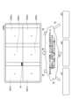
まず、図1A及び図1Bを用いて、第1の実施形態に係るX線診断装置の一例を説明する。図1A及び図1Bは、第1の実施形態に係るX線診断装置の一例を説明するための図である。例えば、X線診断装置は、図1Aに示すように、脳や心臓等の循環器系の診断・治療が実施される検査室R1にCアーム105や天板(テーブル)104を備える装置本体が配置される。そして、図1Aに示す操作室R2に、装置本体を制御するための操作を実行する操作端末が配置される。ここで、検査室R1に配置される装置本体には、図1Bに示すように、手技を実施する医師P1によって操作されるテーブルサイドコンソールや、フットスイッチなどの検査室入力インターフェース109aが備えられる。First Embodiment
First, an example of an X-ray diagnostic apparatus according to the first embodiment will be described with reference to Figs. 1A and 1B. Figs. 1A and 1B are diagrams for explaining an example of an X-ray diagnostic apparatus according to the first embodiment. For example, as shown in Fig. 1A, the X-ray diagnostic apparatus has an apparatus main body including a C-
そして、検査室R1及び操作室R2においては、例えば、複数の検査室モニタ108aと、複数の操作室モニタ108bとがそれぞれ設置される。例えば、検査室モニタ108aは、手技を実施する術者(医師)や看護師などによって観察される。また、操作室モニタ108bは、装置本体を制御するための操作を実行する操作者によって観察される。一例を挙げると、検査室R1においては、手技を実施する医師P1が、検査室モニタ108aに表示された透視画像を観察しながら、X線管102とX線検出器106とを保持するCアーム105を動かし、被検体P3の脳血管内治療などを実施する。また、例えば、操作室R2においては、技師P2などが、医師P1からの指示に応じて、操作室モニタ108bを観察しながら操作室入力インターフェース109bを操作してパラメータの調整などを実施したり、画像に対する各種処理等を実施したりする。なお、検査室R1と操作室R2とを隔てる隔壁には、例えば、窓W1が配置され、窓W1を介して検査室R1内部と操作室R2内部とが相互に確認可能となっている。In the examination room R1 and the operation room R2, for example, a plurality of
次に、第1の実施形態に係るX線診断装置における構成について説明する。図2は、第1の実施形態に係るX線診断装置10の構成の一例を示すブロック図である。図2に示すように、X線診断装置10は、X線高電圧装置101と、X線管102と、X線絞り器103と、天板104と、Cアーム105と、X線検出器106と、メモリ107と、検査室モニタ108aと、操作室モニタ108bと、検査室入力インターフェース109aと、操作室入力インターフェース109bと、処理回路110と、ストレージ111とを備える。Next, the configuration of the X-ray diagnostic apparatus according to the first embodiment will be described. FIG. 2 is a block diagram showing an example of the configuration of the X-ray
ここで、X線管102とX線検出器106とは、撮像部の一例である。また、ストレージ111は、記憶部の一例である。また、検査室モニタ108a及び操作室モニタ108bは、表示部の一例である。また、検査室入力インターフェース109a及び操作室入力インターフェース109bは、保存指示受付部の一例である。Here, the
X線高電圧装置101は、処理回路110による制御の下、X線管102に高電圧を供給する。例えば、X線高電圧装置101は、変圧器(トランス)及び整流器等の電気回路を有し、X線管102に印加する高電圧を発生する高電圧発生装置と、X線管102が照射するX線に応じた出力電圧の制御を行うX線制御装置とを有する。なお、高電圧発生装置は、変圧器方式であってもよいし、インバータ方式であってもよい。The X-ray high voltage device 101 supplies a high voltage to the
X線管102は、熱電子を発生する陰極(フィラメント)と、熱電子の衝突を受けてX線を発生する陽極(ターゲット)とを有する真空管である。X線管102は、X線高電圧装置101から供給される高電圧を用いて、陰極から陽極に向けて熱電子を照射することにより、X線を発生する。The
X線絞り器103は、X線管102により発生されたX線の照射範囲を絞り込むX線絞りと、X線管102から曝射されたX線を調節するフィルタとを有する。The
X線絞り器103におけるX線絞りは、例えば、スライド可能な4枚の絞り羽根を有する。X線絞りは、絞り羽根をスライドさせることで、X線管102が発生したX線を絞り込んで被検体Pに照射させる。ここで、絞り羽根は、鉛などで構成された板状部材であり、X線の照射範囲を調整するためにX線管102のX線照射口付近に設けられる。The X-ray aperture in the
X線絞り器103におけるフィルタは、被検体Pに対する被曝線量の低減とX線画像データの画質向上を目的として、その材質や厚みによって透過するX線の線質を変化させ、被検体Pに吸収されやすい軟線成分を低減したり、X線画像データのコントラスト低下を招く高エネルギー成分を低減したりする。また、フィルタは、その材質や厚み、位置などによってX線の線量及び照射範囲を変化させ、X線管102から被検体Pへ照射されるX線が予め定められた分布になるようにX線を減衰させる。The filter in the
例えば、X線絞り器103は、モータ及びアクチュエータ等の駆動機構を有し、後述する処理回路110による制御の下、駆動機構を動作させることによりX線の照射を制御する。例えば、X線絞り器103は、処理回路110から受け付けた制御信号に応じて駆動電圧を駆動機構に付加することにより、X線絞りの絞り羽根の開度を調整して、被検体Pに対して照射されるX線の照射範囲を制御する。また、例えば、X線絞り器103は、処理回路110から受け付けた制御信号に応じて駆動電圧を駆動機構に付加することにより、フィルタの位置を調整することで、被検体Pに対して照射されるX線の線量の分布を制御する。For example, the
天板104は、被検体Pを載せるベッドであり、図示しない寝台の上に配置される。なお、被検体Pは、X線診断装置10に含まれない。例えば、寝台は、モータ及びアクチュエータ等の駆動機構を有し、後述する処理回路110による制御の下、駆動機構を動作させることにより、天板104の移動・傾斜を制御する。例えば、寝台は、処理回路110から受け付けた制御信号に応じて駆動電圧を駆動機構に付加することにより、天板104を移動させたり、傾斜させたりする。The
Cアーム105は、X線管102及びX線絞り器103と、X線検出器106とを、被検体Pを挟んで対向するように保持する。例えば、Cアーム105は、モータ及びアクチュエータ等の駆動機構を有し、後述する処理回路110による制御の下、駆動機構を動作させることにより、回転したり移動したりする。例えば、Cアーム105は、処理回路110から受け付けた制御信号に応じて駆動電圧を駆動機構に付加することにより、X線管102及びX線絞り器103と、X線検出器106とを被検体Pに対して回転・移動させ、X線の照射位置や照射角度を制御する。なお、図2では、X線診断装置10がシングルプレーンの場合を例に挙げて説明しているが、実施形態はこれに限定されるものではなく、バイプレーンの場合であってもよい。The C-
X線検出器106は、例えば、マトリクス状に配列された検出素子を有するX線平面検出器(Flat Panel Detector:FPD)である。X線検出器106は、X線管102から照射されて被検体Pを透過したX線を検出して、検出したX線量に対応した検出信号を処理回路110へと出力する。なお、X線検出器106は、グリッド、シンチレータアレイ及び光センサアレイを有する間接変換型の検出器であってもよいし、入射したX線を電気信号に変換する半導体素子を有する直接変換型の検出器であっても構わない。The
メモリ107は、例えば、RAM等の半導体メモリ素子により実現される。メモリ107は、処理回路110による処理結果を一時的に記憶する。例えば、メモリ107は、処理回路110によって収集されたX線画像データなどの各種データを受け付けて一時記憶する。ここで、本願におけるX線画像データは、X線検出器106によって検出された検出信号、検出信号に基づいて生成された投影データ、投影データに基づいて生成されたX線画像を含む。なお、メモリ107によって記憶された各種データは、処理回路110の保存処理に応じて、ストレージ111に記憶され、保存される。The
ストレージ111は、フラッシュメモリ等の半導体メモリ素子、ハードディスク、光ディスク等により実現される。ストレージ111は、処理回路110によって収集されたX線画像データなどの各種データを受け付けて記憶する。具体的には、ストレージ111は、処理回路110の保存処理に応じて受け付けた各種データを記憶し、保存する。例えば、ストレージ111は、処理回路110の処理によって生成され、保存処理が実行された静止画像や、動画像などを記憶する。なお、静止画像や動画像については、後に詳述する。The
また、ストレージ111は、処理回路110によって読み出されて実行される各種機能に対応するプログラムを記憶する。なお、ストレージ111は、X線診断装置10とネットワークを介して接続されたサーバ群(クラウド)により実現されることとしてもよい。The
検査室モニタ108a及び操作室モニタ108bは、各種の情報を表示する。例えば、検査室モニタ108a及び操作室モニタ108bは、処理回路110による制御の下、操作者の指示を受け付けるためのGUIや、各種のX線画像を表示する。また、検査室モニタ108a及び操作室モニタ108bは、外部装置から受信した医用画像を表示する。ここで、検査室モニタ108a及び操作室モニタ108bは、複数の医用画像を表示することができる。例えば、検査室モニタ108a及び操作室モニタ108bは、X線画像や、外部装置から受信した医用画像を、複数同時に表示させることができる。The
一例を挙げると、検査室モニタ108a及び操作室モニタ108bは、それぞれ複数のモニタから構成されることで、各モニタにおいて医用画像をそれぞれ表示させることができる。また、例えば、検査室モニタ108a及び操作室モニタ108bは、それぞれ大画面モニタであり、区分された複数の領域において複数の医用画像をそれぞれ表示させることができる。検査室モニタ108a及び操作室モニタ108bは、例えば、液晶ディスプレイやCRTディスプレイである。なお、検査室モニタ108a及び操作室モニタ108bは、一方が複数のモニタで構成され、他方が大画面モニタで構成されてもよい。As an example, the
検査室入力インターフェース109a及び操作室入力インターフェース109bは、操作者からの各種の入力操作を受け付け、受け付けた入力操作を電気信号に変換して処理回路110に出力する。例えば、検査室入力インターフェース109a及び操作室入力インターフェース109bは、マウスやキーボード、トラックボール、スイッチ、ボタン、ジョイスティック、操作面へ触れることで入力操作を行うタッチパッド、表示画面とタッチパッドとが一体化されたタッチスクリーン、光学センサを用いた非接触入力回路、音声入力回路等により実現される。例えば、検査室入力インターフェース109aは、天板104の脇に配置されたテーブルサイドコンソール等である。また、例えば、操作室入力インターフェース109bは、操作室R2の操作卓に配置された種々の入力インターフェースである。The examination
ここで、検査室入力インターフェース109a及び操作室入力インターフェース109bは、検査室モニタ108a及び操作室モニタ108bに表示された医用画像を保存するための保存ボタンをそれぞれ1つ含む。すなわち、検査室入力インターフェース109aは、検査室R1において、検査室モニタ108aにて表示された医用画像を保存するための保存ボタンを1つ含む。また、操作室入力インターフェース109bは、操作室モニタ108bに表示された医用画像を保存するための保存ボタンを1つ含む。Here, the examination
また、検査室入力インターフェース109a及び操作室入力インターフェース109bは、アクティブマーカーを切り替えるためのアクティブマーカー切替ボタンや、予めモニタに紐づけられた専用の機能を実行するための専用ボタンなどをそれぞれ含む。なお、アクティブマーカー、アクティブマーカー切替ボタン、専用ボタンについては、後に詳述する。The examination
処理回路110は、制御機能110a、出力機能110b、特定機能110c及び保存処理機能110dを実行することで、X線診断装置10全体の動作を制御する。ここで、制御機能110aは、操作対象設定部の一例である。また、出力機能110bは、表示制御部の一例である。また、特定機能110cは、対象特定部の一例である。また、保存処理機能110dは、保存部の一例である。The
例えば、処理回路110は、ストレージ111から制御機能110aに相当するプログラムを読み出して実行することにより、X線画像データを収集する。例えば、制御機能110aは、X線高電圧装置101を制御し、X線管102に供給する電圧を調整することで、被検体Pに対して照射されるX線量やオン/オフを制御する。For example, the
また、例えば、制御機能110aは、X線絞り器103の動作を制御し、X線絞りが有する絞り羽根の開度を調整することで、被検体Pに対して照射されるX線の照射範囲を制御する。具体的には、制御機能110aは、X線絞りにおける複数の絞り羽根をスライドさせることにより、複数の絞り羽根で形成される開口部の形状、サイズ、位置を任意に変化させることができる。例えば、制御機能110aは、入力インターフェース109を介してユーザが設定したROIのみにX線が照射されるように、絞り羽根をスライド移動させる。すなわち、制御機能110aは、ユーザによって指定されたROIの形状、サイズ及び位置となるように、絞り羽根をスライド移動させる。For example, the
また、制御機能110aは、X線絞り器103の動作を制御し、フィルタの位置を調整することで、X線の線量の分布を制御する。例えば、制御機能110aは、入力インターフェース109を介してユーザが設定した位置にフィルタを移動させて、X線の線量の分布を制御する。また、制御機能110aは、Cアーム105の動作を制御することで、Cアーム105を回転させたり、移動させたりする。また、例えば、制御機能110aは、寝台の動作を制御することで、天板104を移動させたり、傾斜させたりする。The
また、制御機能110aは、X線検出器106から受信した検出信号に基づいて投影データを生成し、生成した投影データをメモリ107に格納する。また、制御機能110aは、メモリ107が記憶する投影データに対して各種画像処理を行なうことで、X線画像を生成する。また、制御機能110aは、X線画像に対して、例えば、画像処理フィルタによるノイズ低減処理や、散乱線補正を実行する。また、制御機能110aは、回転撮影によって収集した投影データを用いてボリュームデータを再構成し、再構成したボリュームデータからX線画像を生成する。また、制御機能110aは、検査室入力インターフェース109a及び操作室入力インターフェース109bを介して行われる操作の対象を設定する。The
また、処理回路110は、ストレージ111から出力機能110bに相当するプログラムを読み出して実行することにより、検査室モニタ108a及び操作室モニタ108bにGUIやX線画像を表示させる。例えば、出力機能110bは、制御機能110aの制御によって収集されたX線画像をメモリ107から読み出して、検査室モニタ108a及び操作室モニタ108bに表示させる。また、出力機能110bは、操作者の操作に応じてストレージ111に保存された静止画像及び動画像などを検査室モニタ108a及び操作室モニタ108bに表示させる。The
特定機能110cは、操作者による操作に基づいて、保存の対象となる医用画像を特定する。また、保存処理機能110dは、特定機能110cによって特定された医用画像をストレージ111に記憶させる。なお、特定機能110c及び保存処理機能110dによる処理については、後に詳述する。The
以上、X線診断装置10の全体構成について説明した。かかる構成のもと、X線診断装置10は、処理回路110による処理によって、操作性を向上させる。具体的には、X線診断装置10は、操作者による操作に基づいて、保存の対象となる医用画像を特定し、特定した医用画像をストレージ111に記憶することで、操作性を向上させる。The overall configuration of the X-ray
上述したように、X線診断装置では、静止画保存機能が備えられており、術中の参照用の画像や、エビデンスとして残したい画像などを保存するときに使用されている。この静止画保存機能を使用するために用いる静止画保存ボタンの操作性について、静止画保存ボタンが、少なくとも2種類用意されている場合について説明する。かかる場合、2種類以上の保存ボタンのうちいずれの静止画保存ボタンを使うべきなのかをとっさに判断することは、操作者にとって煩わしく、ストレスとなっている。As described above, X-ray diagnostic devices are equipped with a still image saving function that is used to save images for reference during surgery or images that are to be kept as evidence. The operability of the still image saving button used to use this still image saving function will be described below for a case in which at least two types of still image saving buttons are provided. In such a case, it is bothersome and stressful for the operator to quickly decide which of the two or more types of saving buttons to use.
図3は、第1の実施形態に係る複数の静止画保存ボタンによる保存操作の一例を説明するための図である。ここで、図3においては、検査室モニタ208aとして、バイプレーンのL(Lateral)側とF(Frontal)側について、ライブモニタ2081a、参照モニタ2082a及び増設モニタ2083aをそれぞれ備える場合について示す。また、図3においては、静止画保存の対象や、画像加工の対象などを選択するためのアクティブマーカーM1が用いられる場合について示す。アクティブマーカーM1は、画像が表示されるモニタに付与され、アクティブマーカーM1が付与されたモニタ(アクティブモニタ)に表示された画像が、静止画保存や、画像加工などの対象となる。すなわち、術者は、静止画保存ボタンの押下や、画像加工のための操作を実行する前に、静止画保存や、画像加工などを行うモニタ(画像)をアクティブマーカーM1によって選択する。ここで、操作者は、静止画保存や画像加工の対象となる画像が既に表示された状態で、アクティブマーカーM1によってモニタを選択することもできるが、画像が表示される前に、アクティブマーカーM1によってモニタを選択することもできる。FIG. 3 is a diagram for explaining an example of a save operation using a plurality of still image save buttons according to the first embodiment. Here, FIG. 3 shows a case where a
ここで、アクティブマーカーM1は、アクティブマーカー切替ボタン(不図示)によって位置が変更される。例えば、図3に示す検査室モニタ208aは、L側のライブモニタ2081a、参照モニタ2082a及び増設モニタ2083aと、F側のライブモニタ2081a、参照モニタ2082a及び増設モニタ2083aとに、アクティブマーカーM1が表示される領域をそれぞれ含む。操作者は、アクティブマーカー切替ボタンを押下することで、アクティブマーカーM1の位置を切り替える。一例を挙げると、アクティブマーカー切替ボタンが押下されるごとに、アクティブマーカーM1の位置が、L側のライブモニタ2081a、参照モニタ2082a、増設モニタ2083a、F側のライブモニタ2081a、参照モニタ2082a、増設モニタ2083aの順に変化する。操作者は、アクティブマーカー切替ボタンを押下して、複数のモニタの中からアクティブモニタを選択し、その後、いずれかの保存ボタンを押下することで、静止画像を保存させる。Here, the position of the active marker M1 is changed by an active marker switching button (not shown). For example, the
また、図3においては、例えば、保存ボタンとして、透視画像を保存するための透視画像保存ボタンB1、参照画像を保存するための参照画像保存ボタンB2、エビデンスとして残す画像であるエビデンス画像を保存するためのエビデンス画像保存ボタンB3を備える場合について示す。このような状況において、術中に静止画像を保存しようとした場合、操作者は、まず、アクティブマーカー切替ボタンを押下してアクティブマーカーM1の位置を移動させることによってアクティブモニタを選択し、その後、静止画像を保存しようとしている医用画像に対応する保存ボタンを選択して押下することとなる。Also, FIG. 3 shows a case in which the save buttons include a fluoroscopic image save button B1 for saving a fluoroscopic image, a reference image save button B2 for saving a reference image, and an evidence image save button B3 for saving an evidence image that is an image to be kept as evidence. In such a situation, when attempting to save a still image during surgery, the operator first selects the active monitor by pressing the active marker switching button to move the position of the active marker M1, and then selects and presses the save button corresponding to the medical image for which the operator wishes to save a still image.
しかしながら、図3に示すように、モニタが複数あり、保存ボタンも複数ある場合には、操作者(術者)が、術中に適切な組み合わせを即座に判断することは難しい。そこで、本願に係るX線診断装置10では、操作者によって実行された操作に基づいて保存対象となる医用画像を特定し、単一のボタン操作に応じて特定した医用画像を保存するように制御することで、操作性を向上させる。具体的には、X線診断装置10は、操作者が実行した操作のうち、医用画像の保存に関連する操作において、操作者が最後(保存ボタンを押下する直前)に実行した操作に関連付く医用画像を保存対象として特定することで、アクティブマーカーによるアクティブモニタの選択、及び、画像ごとの保存ボタンの使用を省き、操作性を向上させる。すなわち、操作者は、保存ボタンを押下する前に、モニタやボタンを選択する必要がなく、単に保存ボタンを押下するだけで、所望の医用画像の保存処理をX線診断装置10に実行させることができる。以下、X線診断装置10による処理の詳細について説明する。However, as shown in FIG. 3, when there are multiple monitors and multiple save buttons, it is difficult for the operator (surgeon) to immediately determine the appropriate combination during surgery. Therefore, in the X-ray
特定機能110cは、検査室モニタ108a及び操作室モニタ108bに表示される複数の医用画像のうちのいずれかに関する対象操作のうち、最後に実行された対象操作に関連付く医用画像を特定する。具体的には、特定機能110cは、操作者によって実行された操作のうち、検査室モニタ108a及び操作室モニタ108bに表示される医用画像の生成、編集、及び、表示に関する操作のうち少なくとも1つの操作を含む対象操作に関連付く医用画像を特定する。The
ここで、種々の操作が実行される場合、制御機能110aが、検査室入力インターフェース109a及び操作室入力インターフェース109bを介した操作者の操作に応じて、操作の対象を設定する。例えば、制御機能110aは、モニタを選択する操作を受け付けた際に、選択されたモニタを、医用画像の生成、編集、及び、表示などに関する操作の対象として設定する。また、例えば、制御機能110aは、表示された医用画像を選択する操作を受け付けた際に、選択された医用画像を操作の対象として設定する。When various operations are performed, the
なお、医用画像の生成に関する操作は、例えば、造影X線画像の動画から、血流到達時刻その他の血流パラメータの値に応じた色を各画素が有するカラー画像を生成するパラメトリックイメージングに関する操作などを含む。また、医用画像の編集に関する操作は、例えば、種々の画像処理に関する操作などを含む。また、医用画像の表示に関する操作は、例えば、動画像の再生や、停止、コマ送り、カット切替に関する操作などを含む。ここで、カット切替とは、表示対象の動画像を切り替える操作である。Operations related to the generation of medical images include, for example, operations related to parametric imaging, which generates a color image in which each pixel has a color corresponding to the blood flow arrival time or other blood flow parameter value from a video of a contrast X-ray image. Operations related to the editing of medical images include, for example, operations related to various image processing. Operations related to the display of medical images include, for example, operations related to playing, stopping, frame-by-frame advancing, and cut switching of video images. Here, cut switching is an operation to switch the video image to be displayed.
操作者が術中に保存したいと思う医用画像は、その前に何らかの操作が実行された画像である。例えば、透視画像が保存の対象となる場合、操作者によって透視スイッチ(例えば、フットスイッチ)が操作され、透視画像が表示された状態である。また、例えば、複数の撮影画像の中から参照画像として1枚を保存する場合には、操作者は、撮影画像をコマ送りしながらモニタに表示させ、その中から所望の撮影画像を選択する。また、保存の対象となる医用画像は、例えば、画像上で計測処理が実行されたり、編集処理が実行されたりしたものである。このように、保存の対象となる医用画像は、操作者によって何らかの操作が実行されたものである。Medical images that an operator wishes to save during surgery are images on which some operation has been performed beforehand. For example, when a fluoroscopic image is to be saved, the operator operates a fluoroscopic switch (e.g., a foot switch) and the fluoroscopic image is displayed. Also, for example, when saving one of multiple captured images as a reference image, the operator displays the captured images on the monitor while advancing frame by frame, and selects the desired captured image from among them. Also, medical images to be saved are, for example, images on which measurement processing or editing processing has been performed. In this way, medical images to be saved are images on which some operation has been performed by the operator.
そこで、特定機能110cは、操作者によって実行された操作のうち医用画像の保存に関連する操作において、操作者が最後に実行した操作に関連付く医用画像を保存対象として特定する。なお、以下では、操作者が最後に実行した操作をラストオペレーションと記載する。The
例えば、特定機能110cは、ラストオペレーションが透視スイッチの押下であった場合、透視画像を保存対象として特定する。また、例えば、特定機能110cは、ラストオペレーションが医用画像上での計測であった場合、計測された医用画像を保存対象として特定する。また、例えば、特定機能110cは、ラストオペレーションが動画像のコマ送りの後、コマ送りが停止されて1枚の医用画像が表示された場合、当該動画像を保存対象として特定する。また、例えば、特定機能110cは、ラストオペレーションが再生中の動画像の停止の場合、当該動画像を保存対象として特定する。For example, if the last operation was pressing the fluoroscopy switch, the
ここで、特定機能110cは、医用画像の種別に応じて設定された優先度に基づいて、最後に実行された対象操作に関連付く医用画像を特定することができる。すなわち、特定機能110cは、操作者によって操作される各医用画像に対して予め設定された優先度に応じて、保存対象となる医用画像を特定する。例えば、優先度が「透視画像>撮影画像>外部装置から受信した医用画像」である場合、特定機能110cは、透視中は常に透視画像を保存対象として特定する。例えば、特定機能110cは、操作者によって透視スイッチが押下されている間は、常に透視画像を保存対象として特定し、その後に他の医用画像に対する操作が実行された場合でも継続して透視画像を保存対象として特定する。Here, the identifying
このように、特定機能110cは、操作者によるラストオペレーションに関連付く医用画像を保存対象の画像として特定する。ここで、ラストオペレーションは、上述したように、操作者によって実行された操作のうち、検査室モニタ108a及び操作室モニタ108bに表示される医用画像の生成、編集、及び、表示に関する操作のうち少なくとも1つの操作を含むものである。すなわち、こられの操作は、ラストオペレーションとしてみなすか否かを事前に定義しておくことができる。例えば、医用画像の生成、編集、及び、表示に関する全ての操作をラストオペレーションとしてみなす場合でもよく、特定の操作をラストオペレーションとしてみなさない場合でもよい。In this way, the
一例を挙げると、検査室モニタ108aに医用画像を表示させる操作のうち、検査室入力インターフェース109aを介した操作及び操作室入力インターフェース109bを介した操作をともにラストオペレーションとしてみなす場合でもよい。すなわち、医用画像の生成、編集、及び、表示に関する全ての操作について、検査室入力インターフェース109a及び操作室入力インターフェース109bのどちらからの操作もラストオペレーションとして定義される。As an example, among the operations for displaying medical images on the
また、検査室モニタ108aに医用画像を表示させる操作のうち、検査室入力インターフェース109aを介した操作はラストオペレーションとしてみなされ、操作室入力インターフェース109bを介した操作はラストオペレーションとしてみなさない場合でもよい。また、例えば、透視画像を表示させる操作が、ラストオペレーションとして定義されない場合でもよい。すなわち、透視画像は保存対象の画像としてみなされない場合でもよい。また、例えば、外部装置から受信した医用画像に対する操作が、ラストオペレーションとして定義されない場合でもよい。Furthermore, among the operations for displaying medical images on the
ここで、ラストオペレーションとしてみなすか否かの定義は、状況に応じて変更される場合でもよい。例えば、操作者ごとに定義が変更されてもよい。一例を挙げると、操作者が医師Aの場合、透視画像を表示させる操作がラストオペレーションとしてみなされ、操作者が医師Bの場合、透視画像を表示させる操作がラストオペレーションとしてみなされないように、それぞれ定義されてもよい。The definition of whether or not an operation is regarded as the last operation may be changed depending on the situation. For example, the definition may be changed for each operator. As an example, when the operator is Doctor A, the operation of displaying a fluoroscopic image may be defined as being regarded as the last operation, and when the operator is Doctor B, the operation of displaying a fluoroscopic image may not be defined as being the last operation.
なお、特定機能110cによる特定は、X線診断装置10のシステムON/OFFや、プロトコルの切り替え、表示モニタの変更等に伴ってキャンセルするように制御することもできる。すなわち、特定機能110cは、上記した操作が実行された場合に、現時点で特定している医用画像の情報を削除する。The identification by the
このように、特定機能110cによって保存対象の医用画像が特定されると、出力機能110bは、特定された医用画像が識別可能となる情報を検査室モニタ108a及び操作室モニタ108bに表示させる。図4は、第1の実施形態に係る出力機能110bによる処理の一例を示す図である。ここで、図4においては、検査室モニタ108aを対象とした場合の例を示す。また、図4におけるライブモニタ1081aは、現時点で収集されているX線画像(例えば、透視画像等)が表示されるモニタを示し、参照モニタ1082bは参照画像が表示されるモニタを示し、増設モニタ1083aはより情報を表示させるために増設されたモニタを示す。In this way, when the
例えば、操作者によって透視スイッチが操作されて透視画像の収集が開始され、特定機能110cが、保存対象の画像として透視画像を特定すると、出力機能110bは、図4に示すように、透視画像が表示されているライブモニタ1081aにマーカーM3を表示させる。これにより、操作者は現在の保存対象の画像が透視画像であることを一目で確認することができる。このとき、制御機能110aは、操作の対象をマーカーM3が表示されたライブモニタ1081a及び透視画像に設定している。ここで、例えば、操作者が透視スイッチの操作をやめ、参照モニタ1082aに参照画像を表示させる操作を行った場合、特定機能110cが、保存対象の画像として参照画像を特定する。出力機能110bは、この特定に応じて、マーカーM3の表示を参照モニタ1082aに遷移させる。このとき、制御機能110aは、操作の対象をマーカーM3が表示された参照モニタ1082a及び参照画像に設定している。For example, when the operator operates the fluoroscopy switch to start collecting fluoroscopy images and the
なお、図4では、特定された医用画像が識別可能となる情報としてマーカーM3を用いる場合について示したが、実施形態はこれに限定されるものではなく、アクティブマーカーM2を用いる場合でもよい。かかる場合には、出力機能110bは、特定された医用画像が表示されたモニタにアクティブマーカーM2を表示させるように制御する。Note that FIG. 4 shows a case where marker M3 is used as information that enables the identified medical image to be identified, but the embodiment is not limited to this, and active marker M2 may be used. In such a case,
このように、出力機能110bは、特定機能110cによって特定された医用画像を識別するための情報を表示することで、操作者に現在の保存対象となっている医用画像がいずれであるかを容易に確認することを可能にする。なお、出力機能110bは、検査室入力インターフェース109a又は操作室入力インターフェース109bを介した操作に応じて、マーカーM3(或いは、アクティブマーカーM2)の表示位置を変化させることができる。すなわち、意図しない医用画像が保存対象となっている場合に、操作者は、検査室入力インターフェース109a又は操作室入力インターフェース109bを操作して、マーカーM3(或いは、アクティブマーカーM2)の位置を変更することができる。In this way, the
ここで、本実施形態に係るX線診断装置10は、上述したように、アクティブマーカーの位置を移動させるためのアクティブマーカー切替ボタンと、予めモニタに紐づけられた専用の機能を実行するための専用ボタンとを、検査室入力インターフェース109aと操作室入力インターフェース109bにそれぞれ有する。アクティブマーカー切替ボタンは、操作の対象を示すマーカーであるアクティブマーカーの位置を切り替えるボタンである。例えば、操作者が、アクティブマーカー切替ボタンを押下するごとに、検査室モニタ108aにおけるライブモニタ1081a、参照モニタ1082a、増設モニタ1083aの順に、アクティブマーカーの位置が移動する。As described above, the X-ray
例えば、操作者は、アクティブマーカー切替ボタンを押下することによって操作の対象となるモニタ(画像)を選択する。特定機能110cは、この操作をラストオペレーションとみなして、アクティブマーカーが移動されたモニタの医用画像を保存対象として特定する。出力機能110bは、操作者によるアクティブマーカー切替ボタンの押下に応じて、アクティブマーカーの表示位置を移動させる。このように、操作者は、アクティブマーカー切替ボタンを用いたアクティブマーカーの位置の移動をラストオペレーションとすることができる。なお、アクティブマーカーは、保存対象を選択する場合だけでなく、その他種々の操作の対象を選択する際に用いられる。すなわち、操作者は、種々の操作について、アクティブマーカーを用いて対象を選択することができる。For example, the operator selects the monitor (image) to be operated on by pressing the active marker switching button. The
また、予めモニタに紐づけられた専用ボタンは、操作者が特定の機能を用いる場合に押下されるボタンである。ここで、専用ボタンは、検査室モニタ108aに含まれる複数の表示領域(ライブモニタ1081a、参照モニタ1082a、増設モニタ1083a)にそれぞれ紐づけられ、紐づけられた表示領域に表示される医用画像に対する対象操作を受け付ける。なお、専用ボタンは、操作スイッチの一例である。例えば、検査室入力インターフェース109aは、検査室モニタ108aにおける動画像の再生及び停止、コマ送り、カット切替などに対応する専用ボタンが配置される。各ボタンは、例えば、参照モニタ1082aに紐づけられる。そして、各ボタンが押下されると、参照モニタ1082aが操作の対象のモニタとして設定される。そして、参照モニタ1082aに表示された画像に対して、押下されたボタンの処理が実行される。すなわち、専用ボタンは、予め紐づけられたモニタを操作の対象として、表示された画像に対して専用の処理を実行するためのボタンである。The dedicated buttons, which are pre-linked to the monitors, are pressed when the operator uses a specific function. Here, the dedicated buttons are respectively linked to a plurality of display areas (
特定機能110cは、専用ボタンの押下をラストオペレーションとみなして、参照モニタ1082aの医用画像を保存対象として特定する。ここで、専用ボタンが押下された場合、アクティブマーカーの位置の移動は伴わない。すなわち、出力機能110bは、特定機能110cによって特定された参照モニタ1082aにアクティブマーカーを移動させず、現時点の表示位置を維持する。このとき、保存対象は、専用ボタンに対応する画像へと変更されるが、専用ボタンを介さずに行われる操作の対象は、アクティブマーカーが表示された画像のままとなる。換言すると、制御機能110aは、専用スイッチを介さずに行われる操作の対象を設定する。アクティブマーカーは、専用ボタンを介さずに行われる操作の対象を設定する。特定機能110cは、専用ボタンを介した対象操作に応じて、保存対象として特定する医用画像を遷移させる。しかしながら、制御機能110aは、専用ボタンを介した対象操作によっては、操作の対象を変更せず、対象を維持する。The
保存処理機能110dは、検査室入力インターフェース109a及び操作室入力インターフェース109bにより検査室モニタ108a及び操作室モニタ108bに表示される医用画像の保存を指示する操作を受け付けた場合に、特定された医用画像をストレージ111に記憶させる。すなわち、保存処理機能110dは、ラストオペレーションとしてみなされる操作が実行された後に、検査室入力インターフェース109a又は操作室入力インターフェース109bにおける保存ボタンが押下されると、特定機能110cによって特定された医用画像の現時点の画像をメモリ107から読み出してストレージ111に格納する。ここで、保存ボタンは、全ての医用画像に対する保存ボタンとして機能し、検査室入力インターフェース109a及び操作室入力インターフェース109bにそれぞれ1つずつ配置される。When the
例えば、透視画像が保存対象として特定された後に、検査室入力インターフェース109aにおける保存ボタンが押下されると、保存処理機能110dは、保存ボタンが押下された時点の透視画像を静止画像としてストレージ111に格納する。また、例えば、計測が実行された医用画像が保存対象として特定された後に、検査室入力インターフェース109aにおける保存ボタンが押下されると、保存処理機能110dは、保存ボタンが押下された時点の医用画像(例えば、計測された位置や、計測結果などが示された医用画像)をストレージ111に格納する。また、例えば、動画像が保存対象として特定された後に、検査室入力インターフェース109aにおける保存ボタンが押下されると、保存処理機能110dは、保存ボタンが押下された時点の画像を静止画像としてストレージ111に格納する。For example, when a fluoroscopic image is identified as the object to be saved and the save button in the examination
ここで、保存処理機能110dは、特定された医用画像の種別に応じて、保存機能の種類を変更することができる。具体的には、保存処理機能110dは、特定された医用画像の種別に応じて、保存ボタンの押下に対する保存機能の種類を変更する。例えば、保存処理機能110dは、特定された医用画像が透視画像の場合と撮影画像の場合とで、保存ボタンによって受け付けられる操作に対応付ける保存機能の種類を変更する。Here, the
一例を挙げると、保存対象として透視画像が特定された場合、保存処理機能110dは、長押しされずに1回押下された場合には、押下された時点の透視画像を静止画像としてストレージ111に保存し、保存ボタンが長押しされた場合には、押下されている間に収集された透視画像を動画像としてストレージ111に保存する。As an example, when an fluoroscopic image is specified as the object to be saved, if the
また、保存対象として透視画像が特定され、透視の最後に保存ボタンが押下された場合には、保存処理機能110dは、透視中の全ての透視画像を動画像として保存する。この場合、保存処理機能110dは、透視中の透視画像を一時的に記憶しておき、透視後の保存ボタンの押下に応じて、一時的に記憶しておいた全ての透視画像を動画像としてストレージ111に格納する。In addition, when fluoroscopic images are specified as the objects to be saved and the save button is pressed at the end of the fluoroscopic examination, the
また、保存処理機能110dは、特定された医用画像上に付与された付帯情報を、当該医用画像に関連付けてストレージ111に記憶させることもできる。具体的には、保存処理機能110dは、医用画像上の付与された位置に関連付けて、付帯情報をストレージ111に記憶させる。上述したように、X線診断装置10は、計測に用いられた医用画像等を保存の対象として特定し、特定した医用画像をストレージ111に記憶させる。ここで、保存処理機能110dは、計測時の情報(計測位置や計測結果など)が重畳された医用画像をそのままストレージ111に格納することもできるが、重畳された情報と医用画像とをそれぞれ別々に記憶させ、相互に関連付けを行うこともできる。The
すなわち、保存処理機能110dは、計測位置を示す直線や計測結果などの情報を、医用画像において重畳されていた位置に関連付けて別々に保存する。これにより、記憶された情報を後に読み出して表示させる際に、出力機能110bは、医用画像のみの表示や、選択した情報のみを医用画像に重畳させた重畳画像などを表示させることができる。医用画像に関連付けて保存される付帯情報は、上記した計測に関する情報だけではなく、例えば、アノテーションや、ピクトグラム、その他の解析結果なども含まれる。In other words, the
医用画像上に重畳される解析結果としては、例えば、FFR(Fractional Flow Reserve)や、iFR(instantaneous wave-Free Ratio)などがある。例えば、保存対象として特定された造影画像上にFFR、iFR等の指標に基づく表示が重畳されている場合、保存処理機能110dは、重畳して得た表示画像そのものを保存してもよいが、重畳対象画像(造影画像)と、重畳する情報(FFR、iFR等)とを関連付けて保存する。すなわち、保存処理機能110dは、造影画像と重畳する情報とを、重畳する位置の情報(位置合せ情報)とともに関連付けて保存する。Examples of analysis results that are superimposed on medical images include FFR (Fractional Flow Reserve) and iFR (instantaneous wave-free ratio). For example, when a display based on indices such as FFR and iFR is superimposed on a contrast image identified as the target for storage, the
このように、医用画像と付帯情報とを関連付けて保存する場合、保存処理機能110dは、例えば、保存時の表示態様をデフォルトの設定として保存する。これにより、再度表示させる際に、保存時と同じ表示ができるため、付帯情報があることが最初の表示でわかり、付帯情報のON/OFFの切り替えを含む表示態様を後から任意に変更することが可能となる。When a medical image and its associated information are saved in this manner, the
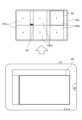
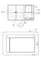
図5は、第1の実施形態に係る医用画像上に付加される情報の一例を示す図である。ここで、図5においては、造影画像上にiFRの情報が対応付けられた場合を示す。具体的には、図5は、造影画像における血管の各位置にiFRの絶対値に応じた色が付けられ、各位置のiFR降下率が血管の脇のプロットによって示されている。なお、iFRの降下率は、隣接する計測位置間でiFRの絶対値が降下した割合を示し、図5においては、降下率が高いほど、血管の走行方向に直交する方向に並べられるプロットの数が増える。例えば、狭窄などによりiFRの絶対値が大きく変化する位置(図中の色の変化が大きい位置)において、プロットの数が増える。Figure 5 is a diagram showing an example of information added to a medical image according to the first embodiment. Here, Figure 5 shows a case where iFR information is associated with a contrast image. Specifically, in Figure 5, each position of a blood vessel in a contrast image is colored according to the absolute value of iFR, and the iFR drop rate at each position is shown by a plot beside the blood vessel. The drop rate of iFR indicates the rate at which the absolute value of iFR drops between adjacent measurement positions, and in Figure 5, the higher the drop rate, the more plots are arranged in a direction perpendicular to the running direction of the blood vessel. For example, the number of plots increases at positions where the absolute value of iFR changes significantly due to stenosis or the like (positions where the color change in the figure is large).
このようなiFRの情報が対応付けられた造影画像が特定機能110cによって保存対象として特定され、操作者によって保存ボタンが押下されると、保存処理機能110dは、図5に示す状態をデフォルトとして設定して、造影画像と、iFRのデータ(値と計測位置)と、表示の設定情報(iFRをどのように表示させていたか)とをストレージ111に格納する。表示の設定情報としては、例えば、iFRの各値を色分けして表示させること、iFRの各値に対応する色情報、iFRの降下率を血管の脇にプロットで表示させること、プロット1つに対応するiFRの降下率などの情報を含む。これにより、図5のiFRの情報が対応付けられた造影画像を再度表示させた際に、操作者は、iFR降下率のプロット表示とiFRの絶対値に基づく色分け表示とを切り替えたり、プレッシャーワイヤ―のガイドライン(始点・終点の設定を含む)を修正したりすることができる。When the contrast image associated with such iFR information is identified as a storage target by the
上述した実施形態では、透視画像や撮影画像などを保存する場合を例に挙げて説明した。しかしながら、実施形態はこれに限定されるものではなく、例えば、外部装置から受信した医用画像を保存の対象とすることもできる。図2では図示していないが、X線診断装置10は、ネットワークを介して他のモダリティや周辺機器と接続され、それらの装置から受信した医用画像を検査室モニタ108a又は操作室モニタ108bに表示させることができる。In the above-described embodiment, an example has been described in which fluoroscopic images, photographed images, etc. are stored. However, the embodiment is not limited to this, and for example, medical images received from an external device can also be stored. Although not shown in FIG. 2, the X-ray
かかる場合には、特定機能110cは、外部装置から受信した医用画像に関するラストオペレーションに基づいて、当該医用画像を保存対象として特定する。保存処理機能110dは、保存ボタンの押下に応じて、当該医用画像をストレージ111に格納する。ここで、保存処理機能110dは、検査室モニタ108a又は操作室モニタ108bに表示された医用画像をキャプチャして、キャプチャ画像をストレージ111に格納する場合でもよく、或いは、受信した医用画像のデータをメモリ107から読み出してストレージ111に格納する場合でもよい。In such a case, the
このように、保存処理機能110dによって医用画像が保存されると、出力機能110bは、ストレージ111に記憶される医用画像を検査室モニタ108a又は操作室モニタ108bに表示させる。すなわち、術中に保存される医用画像は、術中に観察したい場合が多いため、出力機能110bは、保存された医用画像を検査室モニタ108a又は操作室モニタ108bに表示させる。In this way, when the medical image is saved by the saving
ここで、出力機能110bは、特定された医用画像の種別ごとに設定された表示位置、非表示状態の表示位置、特定された医用画像が表示されていた表示位置にて、ストレージ111に記憶させる医用画像を表示させる。例えば、出力機能110bは、保存された医用画像を検査室モニタ108a又は操作室モニタ108bに表示させる際に、透視画像、撮影画像、外部装置から受信した医用画像を、予め決められたモニタにて表示させる。また、例えば、出力機能110bは、ストレージ111に記憶される医用画像を、現時点で何も表示されていないモニタに表示させる。また、例えば、出力機能110bは、ストレージ111に記憶させる医用画像が表示されていたモニタに継続して表示させる。Here, the
ここで、出力機能110bは、特定された医用画像の種別に応じて、ストレージ111に記憶させる医用画像を表示させるか否かを決定する。すなわち、出力機能110bは、特定の画像種が保存された場合に、保存した医用画像を表示しないように制御することもできる。例えば、外部装置から受信した医用画像をストレージ111に保存する場合には、既に検査室モニタ108a又は操作室モニタ108bに表示済みであるため、出力機能110bは、当該医用画像を表示対象としない。The
上述した実施形態では、撮像部がシングルプレーンの場合について説明した。しかしながら、実施形態はこれに限定されるものではなく、撮像部がバイプレーンである場合でもよい。すなわち、撮像部が、それぞれX線管102とX線検出器106とを備える第1の撮像系(例えば、L側)と第2の撮像系(例えば、F側)とを有し、検査室モニタ108a及び操作室モニタ108bが、第1の撮像系により撮像されるX線画像を含む複数の医用画像と、第2の撮像系により撮像されるX線画像を含む複数の医用画像とをそれぞれ表示可能な場合でも、X線診断装置10は、上記と同様に、保存処理を行うことができる。In the above-described embodiment, the imaging unit is a single plane. However, the embodiment is not limited to this, and the imaging unit may be a biplane. That is, even if the imaging unit has a first imaging system (e.g., L side) and a second imaging system (e.g., F side) each having an
かかる場合には、検査室入力インターフェース109a及び操作室入力インターフェース109bは、検査室モニタ108a及び操作室モニタ108bに表示される第1の撮像系に関する医用画像及び第2の撮像系に関する医用画像の保存を指示する操作をそれぞれ受け付ける。すなわち、検査室入力インターフェース109a及び操作室入力インターフェース109bは、第1の撮像系に関する医用画像の保存を指示する操作及び第2の撮像系に関する医用画像の保存を指示する操作を、一括又は各々受け付ける。例えば、検査室入力インターフェース109a及び操作室入力インターフェース109bは、L側に関する医用画像の保存及びF側に関する医用画像の保存を、保存ボタンの押下によって受け付ける。In such a case, the examination
例えば、ラストオペレーションが両方の医用画像に関する操作であった場合には、検査室入力インターフェース109a及び操作室入力インターフェース109bは、保存ボタンの押下をL側に関する医用画像の保存及びF側に関する医用画像の保存として受け付ける。また、例えば、ラストオペレーションが一方の医用画像に関する操作であった場合には、検査室入力インターフェース109a及び操作室入力インターフェース109bは、保存ボタンの押下をラストオペレーションに関する医用画像の保存として受け付ける。なお、検査室入力インターフェース109a及び操作室入力インターフェース109bは、常に、保存ボタンの押下をL側に関する医用画像の保存及びF側に関する医用画像の保存として受け付ける場合でもよい。For example, if the last operation was an operation related to both medical images, the examination
特定機能110cは、第1の撮像系に関する医用画像及び第2の撮像系に関する医用画像について、最後に実行された対象操作に関連付く医用画像をそれぞれ特定する。また、保存処理機能110dは、保存ボタンによって医用画像の保存を指示する操作を受け付けた場合に、特定された医用画像をストレージ111にそれぞれ記憶させる。The
図6は、第1の実施形態に係る出力機能による処理の一例を示す図である。ここで、図6においては、検査室モニタ108aを対象とした場合の例を示す。また、図6においては、検査室モニタ108aとして、バイプレーンのL側とF側について、ライブモニタ1081a、参照モニタ1082a及び増設モニタ1083aをそれぞれ備える場合について示す。Figure 6 is a diagram showing an example of processing by the output function according to the first embodiment. Here, Figure 6 shows an example in which the
例えば、操作者によってL側の透視スイッチが操作されて透視画像の収集が開始され、特定機能110cが、保存対象の画像として透視画像を特定すると、出力機能110bは、図6に示すように、透視画像が表示されているライブモニタ1081aにマーカーM3を表示させる。その後、操作者が保存ボタンを押下すると、保存処理機能110dは、L側のライブモニタ1081aにて表示されている透視画像において保存ボタンが押下された時点の透視画像をストレージ111に格納する。For example, when the operator operates the L-side fluoroscopy switch to start collecting fluoroscopy images and the
上述した実施形態では、検査室R1にて術中の術者によって操作が実行される場合について説明した。しかしながら、実施形態はこれに限定されるものではなく、検査室R1と操作室R2でそれぞれ操作が実行される場合でもよい。すなわち、検査室入力インターフェース109a及び操作室入力インターフェース109bにおいてそれぞれ保存ボタンが押下された場合でも、X線診断装置10は、上記と同様に、保存処理を行うことができる。In the above-described embodiment, a case has been described in which operations are performed by the surgeon during surgery in examination room R1. However, the embodiment is not limited to this, and operations may be performed in both examination room R1 and operation room R2. In other words, even when the save button is pressed in each of the examination
かかる場合には、特定機能110cは、検査室R1及び操作室R2それぞれにおいて最後に実行された対象操作に関連付く医用画像をそれぞれ特定する。すなわち、特定機能110cは、検査室R1におけるラストオペレーションに関連する医用画像と、操作室R2におけるラストオペレーションに関連する医用画像とをそれぞれ特定する。例えば、医師Aが操作室R2で参照モニタ1082a上の医用画像に対して距離計測を行っているときに、医師Bが検査室R1で透視スイッチを踏んで、ライブモニタ1081aに透視画像を表示させながら手技を開始すると、特定機能110cは、操作室R2の保存対象として距離計測を行っている医用画像を特定し、検査室R1の保存対象として透視画像を特定する。In such a case, the identifying
保存処理機能110dは、検査室R1における保存ボタンによって受け付けた操作に応じて特定された医用画像をストレージ111に格納し、操作室R2における保存ボタンによって受け付けた操作に応じて、特定された医用画像をストレージ111に格納する。例えば、保存処理機能110dは、検査室R1において保存ボタンが押下されると、保存ボタンが押下された時点の透視画像をストレージ111に格納する。また、操作室R2において保存ボタンが押下されると、保存ボタンが押下された時点の距離計測に用いられた医用画像をストレージ111に格納する。The
ここで、検査室R1と操作室R2でそれぞれ操作が実行される場合、出力機能110bは、検査室モニタ108a及び操作室モニタ108bにラストオペレーションによって特定されている医用画像を識別するためのマーカーをそれぞれ表示させる。図7は、第1の実施形態に係る第1の実施形態に係る出力機能による処理の一例を示す図である。ここで、ここで、図7においては、検査室モニタ108aと操作室モニタ108bを上下にそれぞれ示す。また、図7においては、各室のモニタとして、バイプレーンのL側とF側について、ライブモニタ1081a、参照モニタ1082a及び増設モニタ1083aをそれぞれ備える場合について示す。When operations are performed in the examination room R1 and the operation room R2, the
例えば、医師Aが操作室R2で参照モニタ1082a上の医用画像に対して距離計測を行うと、出力機能110bは、図7の操作室の保存対象に示すように、操作室モニタ108bにおける参照モニタ1082aにマーカーM3を表示させる。また、例えば、医師Bが検査室R1で透視スイッチを踏んで、ライブモニタ1081aに透視画像を表示させると、出力機能110bは、図7の検査室の保存対象に示すように、検査室モニタ108aのライブモニタ1081aにマーカーM3を表示させる。For example, when Doctor A performs distance measurement on the medical image on the
上述した例では、検査室R1の操作者による保存操作と、操作室R2における操作者による保存操作とをそれぞれ実行する場合について説明した。しかしながら、どちらか一方の操作による保存操作を行う場合でもよい。かかる場合には、特定機能110cは、例えば、検査室R1の操作者による操作と、操作室R2における操作者による操作のうち、最後に操作があった医用画像を保存対象として特定する。In the above example, a case has been described in which a save operation is performed by an operator in examination room R1 and a save operation is performed by an operator in operation room R2. However, a save operation may be performed by only one of the operations. In such a case, the
ここで、検査室R1の操作者による操作と、操作室R2における操作者による操作のうち一方の操作によって保存対象を特定する場合、優先度が設定されてもよい。例えば、特定機能110cは、検査室R1にて最後に実行された対象操作に関連付く医用画像を優先的に特定する。保存処理機能110dは、検査室入力インターフェース109aにおける保存ボタンが押下された場合に、特定された医用画像をストレージ111に記憶させる。例えば、検査室R1では、手技に必要な画像(例えば、透視画像等)が観察される。したがって、検査室R1での操作を優先的にラストオペレーションとすることで、手技に必要な画像を優先的に保存することができる。Here, when identifying the object to be saved by either the operation by the operator in examination room R1 or the operation by the operator in operation room R2, a priority may be set. For example, the
また、上述したように、本実施形態に係る操作室入力インターフェース109bは、アクティブマーカーの位置を移動させるためのアクティブマーカー切替ボタンが配置され、アクティブマーカー切替ボタンの押下を受け付けることで、アクティブマーカーM2の位置を移動させることができる。ここで、操作室入力インターフェース109bにおけるアクティブマーカー切替ボタンが押下された場合には、アクティブマーカーM2の位置が移動するとともに、操作室R2におけるラストオペレーションのみが移動する。As described above, the control
すなわち、特定機能110cは、アクティブマーカー切替ボタンの押下をラストオペレーションとして保存対象の医用画像を特定する場合に、操作室入力インターフェース109bにおけるアクティブマーカー切替ボタンが押下された場合には、検査室R1にて特定したラストオペレーションを更新せず、操作室R2にて特定したラストオペレーションのみを更新する。以下、検査室R1の操作者による操作と、操作室R2における操作者による操作のうち、最後に操作があった医用画像を保存対象として特定する場合を一例に挙げて説明する。かかる状況において、検査室R1の操作者による操作がラストオペレーションとして特定されており、その後、操作室入力インターフェース109bにおけるアクティブマーカー切替ボタンが押下された場合には、特定機能110cは、検査室R1におけるラストオペレーションを維持した状態で、操作室入力インターフェース109bにおけるアクティブマーカー切替ボタンの押下を、操作室R2におけるラストオペレーションとして判定する。すなわち、特定機能110cは、検査室R1の操作者によるラストオペレーションに基づく医用画像と、操作室R2における操作者によるラストオペレーションに基づく医用画像とをそれぞれ特定するように処理を切り替える。That is, when the
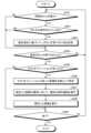
次に、図8を用いて、X線診断装置10による処理の手順の一例を説明する。図8は、第1の実施形態に係るX線診断装置10の処理の流れを示すフローチャートである。ここで、図8においては、ラストオペレーションに優先度が設けられた場合について示す。なお、図8におけるステップS101~S105は、処理回路110が、特定機能110cに対応するプログラムを読み出して実行することにより実現されるステップである。ステップS106は、処理回路110が、保存処理機能110dに対応するプログラムを読み出して実行することにより実現されるステップである。ステップS107は、処理回路110が、出力機能110bに対応するプログラムを読み出して実行することにより実現されるステップである。ステップS108は、処理回路110が、制御機能110aに対応するプログラムを読み出して実行することにより実現されるステップである。Next, an example of the procedure of processing by the X-ray
第1の実施形態に係るX線診断装置10においては、処理回路110が、保存ボタンが押下されたか否かを判定する(ステップS101)。ここで、保存ボタンが押下された場合には(ステップS101肯定)、処理回路110は、優先されるラストオペレーションがあったか否かを判定する(ステップS102)。なお、保存ボタンが押下されるまで、処理回路110はステップS101の判定を継続する(ステップS101否定)。In the X-ray
ここで、優先されるラストオペレーションがあった場合には(ステップS102肯定)、処理回路110は、ラストオペレーションがあった画像を対象として特定し(ステップS103)、特定した画像の種別に応じて適切な保存機能を実行する(ステップS104)。If there is a last operation that takes priority (Yes in step S102), the
その後、処理回路110は、保存した画像を検査室モニタ108a及び操作室モニタ108bに表示させ(ステップS105)、処理が終了か否か判定する(ステップS106)。ここで、処理が終了の場合(ステップS106肯定)、処理回路110は、終了する。一方、処理が終了ではない場合(ステップS106否定)、処理回路110は、ステップS101に戻って、保存ボタンが押下されたか否かの判定を継続する。なお、ステップS102において、優先されるラストオペレーションがない場合には(ステップS102否定)、処理回路110は、ステップS106の判定を実行する。Then, the
上述したように、第1の実施形態によれば、ストレージ111は、医用画像を記憶可能である。撮像部は、被検体にX線を照射するX線管102とX線管102から発せられるX線を検出するX線検出器106とを含む。検査室モニタ108a及び操作室モニタ108bは、撮像部により撮像されるX線画像を含む複数の医用画像を表示可能である。検査室入力インターフェース109a及び操作室入力インターフェース109bは、検査室モニタ108a及び操作室モニタ108bに表示される医用画像の保存を指示する操作を受け付ける。特定機能110cは、検査室モニタ108a及び操作室モニタ108bに表示される複数の医用画像のうちのいずれかに関する対象操作のうち、最後に実行された対象操作に関連付く医用画像を特定する。保存処理機能110dは、検査室入力インターフェース109a及び操作室入力インターフェース109bにより検査室モニタ108a及び操作室モニタ108bに表示される医用画像の保存を指示する操作を受け付けた場合に、特定された医用画像をストレージ111に記憶させる。従って、第1の実施形態に係るX線診断装置10は、単一の保存ボタンの操作で所望の医用画像を保存することができ、操作性を向上させることを可能にする。As described above, according to the first embodiment, the
また、第1の実施形態によれば、保存処理機能110dは、特定された医用画像の種別に応じて、保存機能の種類を変更する。従って、第1の実施形態に係るX線診断装置10は、画像ごとに適切な種類で保存することを可能にする。Furthermore, according to the first embodiment, the saving
また、第1の実施形態によれば、保存処理機能110dは、特定された医用画像が透視画像の場合と撮影画像の場合とで、検査室入力インターフェース109a及び操作室入力インターフェース109bによって受け付けられる操作に対応付ける保存機能の種類を変更する。従って、第1の実施形態に係るX線診断装置10は、透視画像と撮影画像とをそれぞれ適切に保存することを可能にする。Furthermore, according to the first embodiment, the
また、第1の実施形態によれば、特定機能110cは、検査室モニタ108a及び操作室モニタ108bに表示される医用画像の生成、編集、及び、表示に関する操作のうち少なくとも1つの操作を含む対象操作に関連付く医用画像を特定する。従って、第1の実施形態に係るX線診断装置10は、画像の保存とは無関係な操作をラストオペレーションとすることを回避することを可能にする。Furthermore, according to the first embodiment, the
また、第1の実施形態によれば、特定機能110cは、医用画像の種別に応じて設定された優先度に基づいて、最後に実行された対象操作に関連付く医用画像を特定する。従って、第1の実施形態に係るX線診断装置10は、画像の種別に応じて優先的に保存することを可能にする。Furthermore, according to the first embodiment, the
また、第1の実施形態によれば、撮像部は、それぞれX線管102とX線検出器106とを備える第1の撮像系と第2の撮像系とを有する。検査室モニタ108a及び操作室モニタ108bは、第1の撮像系により撮像されるX線画像を含む複数の医用画像と、第2の撮像系により撮像されるX線画像を含む複数の医用画像とをそれぞれ表示可能である。検査室入力インターフェース109a及び操作室入力インターフェース109bは、検査室モニタ108a及び操作室モニタ108bに表示される第1の撮像系に関する医用画像及び第2の撮像系に関する医用画像の保存を指示する操作をそれぞれ受け付ける。特定機能110cは、第1の撮像系に関する医用画像及び第2の撮像系に関する医用画像について、最後に実行された対象操作に関連付く医用画像をそれぞれ特定する。保存処理機能110dは、検査室入力インターフェース109a及び操作室入力インターフェース109bにより検査室モニタ108a及び操作室モニタ108bに表示される医用画像の保存を指示する操作を受け付けた場合に、特定された医用画像をストレージ111にそれぞれ記憶させる。従って、第1の実施形態に係るX線診断装置10は、バイプレーンにおけるL側及びF側のそれぞれについて医用画像保存することを可能にする。According to the first embodiment, the imaging unit has a first imaging system and a second imaging system each including an
また、第1の実施形態によれば、検査室入力インターフェース109a及び操作室入力インターフェース109bは、第1の撮像系に関する医用画像の保存を指示する操作及び第2の撮像系に関する医用画像の保存を指示する操作を、一括又は各々受け付ける。従って、第1の実施形態に係るX線診断装置10は、種々の状況において、適切に医用画像を保存することを可能にする。Furthermore, according to the first embodiment, the examination
また、第1の実施形態によれば、医用画像は、X線診断装置10の外部から受け付けた医用画像を含む。従って、第1の実施形態に係るX線診断装置10は、検査室モニタ108a及び操作室モニタ108bに表示される全ての医用画像を対象として保存処理を実行することを可能にする。Furthermore, according to the first embodiment, the medical images include medical images received from outside the X-ray
また、第1の実施形態によれば、保存処理機能110dは、特定された医用画像上に付与された付帯情報を、当該医用画像に関連付けてストレージ111に記憶させる。従って、第1の実施形態に係るX線診断装置10は、医用画像と付帯情報とをそれぞれ表示させることを可能にする。Furthermore, according to the first embodiment, the
また、第1の実施形態によれば、保存処理機能110dは、医用画像上の付与された位置に関連付けて、付帯情報をストレージ111に記憶させる。従って、第1の実施形態に係るX線診断装置10は、付帯情報が付与された医用画像を種々の形態で表示させることを可能にする。Furthermore, according to the first embodiment, the saving
また、第1の実施形態によれば、検査室モニタ108a及び操作室モニタ108bは、撮像部による撮像が実施される検査室と、X線診断装置10を操作する操作室のそれぞれに配置される。検査室入力インターフェース109a及び操作室入力インターフェース109bは、撮像部による撮像が実施される検査室と、X線診断装置を操作する操作室のそれぞれに配置される。特定機能110cは、検査室及び操作室それぞれにおいて最後に実行された対象操作に関連付く医用画像をそれぞれ特定する。保存処理機能110dは、検査室における検査室入力インターフェース109aによって受け付けた操作に応じて、及び、操作室における操作室入力インターフェース109bによって受け付けた操作に応じて、特定された医用画像をストレージ111にそれぞれ記憶させる。従って、第1の実施形態に係るX線診断装置10は、検査室R1と操作室R2のそれぞれの医用画像の保存処理に関して操作性を向上させることを可能にする。According to the first embodiment, the
また、第1の実施形態によれば、特定機能110cは、検査室にて最後に実行された対象操作に関連付く医用画像を優先的に特定する。従って、第1の実施形態に係るX線診断装置10は、手技を行う検査室での保存処理を優先して行うことを可能にする。Furthermore, according to the first embodiment, the
また、第1の実施形態によれば、出力機能110bは、ストレージ111に記憶させる医用画像を検査室モニタ108a及び操作室モニタ108bに表示させる。従って、第1の実施形態に係るX線診断装置10は、手技中に観察が望まれる医用画像を即座に表示させることを可能にする。Furthermore, according to the first embodiment, the
また、第1の実施形態によれば、出力機能110bは、特定された医用画像の種別ごとに設定された表示位置、非表示状態の表示位置、特定された医用画像が表示されていた表示位置にて、ストレージ111に記憶させる医用画像を表示させる。従って、第1の実施形態に係るX線診断装置10は、状況に応じて適切な位置に医用画像を表示させることを可能にする。Furthermore, according to the first embodiment, the
また、第1の実施形態によれば、出力機能110bは、特定された医用画像の種別に応じて、ストレージ111に記憶させる医用画像を表示させるか否かを決定する。従って、第1の実施形態に係るX線診断装置10は、不要な医用画像の表示を回避することを可能にする。Furthermore, according to the first embodiment, the
また、第1の実施形態によれば、出力機能110bは、特定された医用画像が識別可能となる情報を検査室モニタ108a及び操作室モニタ108bに表示させる。従って、第1の実施形態に係るX線診断装置10は、保存の対象となっている医用画像を一目で把握することを可能にする。Furthermore, according to the first embodiment, the
また、第1の実施形態によれば、専用スイッチは、検査室モニタ108a及び操作室モニタ108bに含まれる複数の表示領域(ライブモニタ、参照モニタ、増設モニタなど)にそれぞれ紐づけられ、紐づけられた表示領域に表示される医用画像に対する対象操作を受け付ける。制御機能110aは、専用ボタンを介さずに行われる操作の対象を設定する。検査室モニタ108a及び操作室モニタ108bは、専用ボタンを介さずに行われる操作の対象を特定するためのアクティブマーカーを表示する。特定機能110cは、専用ボタンを介した対象操作に応じて、特定する医用画像を遷移させる一方、制御機能110aは、専用ボタンを介した対象操作によっては、設定する対象を変更しない。従って、第1の実施形態に係るX線診断装置10は、専用ボタンの利便性を維持しつつ、操作性を向上させることを可能にする。According to the first embodiment, the dedicated switch is linked to each of a plurality of display areas (such as a live monitor, a reference monitor, and an additional monitor) included in the
(第2の実施形態)
第1の実施形態では、複数の操作者が検査室R1と操作室R2においてそれぞれ操作する場合について説明した。第2の実施形態では、複数の操作者が検査室R1でそれぞれ操作する場合について説明する。図9は、第2の実施形態に係るX線診断装置10の構成の一例を示すブロック図である。なお、第2の実施形態に係るX線診断装置10は、第1の実施形態と比較して、端末装置120を含む点と、出力機能110b、特定機能110cによる処理が異なる。以下、これらを中心に説明する。Second Embodiment
In the first embodiment, a case where multiple operators operate in the examination room R1 and the operation room R2, respectively, has been described. In the second embodiment, a case where multiple operators operate in the examination room R1, respectively, will be described. FIG. 9 is a block diagram showing an example of the configuration of an X-ray
第2の実施形態に係るX線診断装置10においては、端末装置120が検査室R1に配置される。すなわち、検査室R1には、テーブルサイドコンソール等の検査室入力インターフェース109aの他に、検査室入力インターフェース109aとしての端末装置120が配置される。In the X-ray
端末装置120は、X線診断装置10に対して遠隔操作が可能なリモートコンソールや、無線通信によってX線診断装置10に対してアクセス可能に接続され、X線診断装置10の入力インターフェースを遠隔操作するアプリケーションが実行されるタブレット端末などである。このようなタブレット端末は、例えば、タブレット端末によって受け付けられた操作を、無線を介してX線診断装置が受信することで、入力インターフェースのマウスやキーボード等を遠隔操作する。一例を挙げると、検査室R1にいる操作者が、タブレット端末のタッチパネルをタッチパッドとして用いて検査室モニタ108aに表示されたポインタを操作することで、検査室ディスプレイ上に表示されたGUIに対して操作を実行する。ここで、タブレット端末のタッチパネルの表示と検査室モニタ108aの表示とを同期させることもできる。The
第2の実施形態に係る特定機能110cは、検査室における検査室入力インターフェース109a及び端末装置120を操作する操作者によって最後に実行された対象操作に関連付く医用画像をそれぞれ特定する。すなわち、特定機能110cは、検査室入力インターフェース109aにおけるラストオペレーションに関連する医用画像と、端末装置120におけるラストオペレーションに関連する医用画像とをそれぞれ特定する。The
第2の実施形態に係る保存処理機能110dは、検査室入力インターフェース109a及び端末装置120によって受け付けた操作に応じて、特定された医用画像をストレージ111にそれぞれ記憶させる。例えば、保存処理機能110dは、検査室入力インターフェース109aにおける操作に応じて透視画像をストレージ111に記憶させ、端末装置120における操作に応じて撮影画像をストレージ111に記憶させる。The
ここで、第2の実施形態では、1つの医用画像の保存に対して、検査室入力インターフェース109aからの操作と端末装置120からの操作とを受け付けることもできる。すなわち、複数の操作者が検査室入力インターフェース109aと端末装置120を操作しながら、1つの医用画像を保存させるように構成することもできる。Here, in the second embodiment, it is also possible to accept operations from the examination
かかる場合には、例えば、特定機能110cは、検査室入力インターフェース109aによる操作と端末装置120による操作のうち、より後の操作をラストオペレーションとして特定する。ここで、検査室入力インターフェース109aによる操作と端末装置120による操作のうち、より後の操作をラストオペレーションとして特定すると、操作の競合により、保存対象の医用画像がめまぐるしく入れ替わる可能性がある。In such a case, for example, the
そこで、特定機能110cは、操作や入力インターフェースに設けられた優先度に応じて、ラストオペレーションを決めることもできる。例えば、特定機能110cは、X線画像の収集に関連する操作を、最後に実行された対象操作として優先的に選択する。例えば、透視を出している間は、術者の関心はライブモニタ1081aにある。そのため、特定機能110cは、透視を出している間のみ保存対象を透視画像として決定し、透視を終えたら直前に操作していた医用画像に保存対象を戻すことができる。The
これは、検査室で複数人が同時に装置を操作しているシーンで必要な仕組みである。例えば、医師Aが透視を見ながらカテをすすめ、医師Bが参照モニタ1082aで画像の編集をおこなっているとする。X線画像の収集を優先としていなければ、医師Aが透視中に静止画保存をしたいと思ったとき、医師Bが参照モニタ1082aの画像を操作していると、保存対象が参照モニタ1082aに表示された医用画像となるため、ライブモニタ1081aの透視画像が保存できなくなってしまう。そこで、特定機能110cは、X線画像が収集されている場合には、収集されているX線画像を保存対象として優先的に特定する。This is a necessary mechanism in situations where multiple people are operating the device at the same time in an examination room. For example, suppose that Doctor A is inserting a catheter while observing the fluoroscopy, while Doctor B is editing the image on the
また、例えば、特定機能110cは、検査室に配置された検査室入力インターフェース109a及び端末装置120に対して設定された優先度に応じて、最後に実行された対象操作に関連付く医用画像を特定する。一例を挙げると、優先度は、「テーブルサイドコンソール>端末装置」と設定される。For example, the
かかる場合には、特定機能110cは、テーブルサイドコンソールによる操作に関する医用画像を優先して保存対象と特定する。ここで、例えば、特定機能110cは、テーブルサイドコンソールから操作を受け付けてから一定の時間が経過するまで、テーブルサイドコンソールの優先を継続するようにしてもよい。In such a case, the
この時、端末装置120がタブレット端末の場合、タブレット端末における保存スイッチが、システムにおける全体の統一の保存スイッチではなく、タブレット端末限定の保存機能に切り替わる場合でもよい。すなわち、テーブルサイドコンソールでの操作が優先される場合、タブレット端末では、タブレット端末限定での保存が可能となる。その場合、操作者は、例えば、タブレット端末を操作して再度医用画像を表示させ、その画像に対する保存操作を実行することができる。この場合、保存ボタンのGUIはそのままで機能のみが切り替えられる場合でもよく、或いは、GUIのデザイン(アイコン)が変化する場合でもよい。At this time, if the
ここで、タブレット端末が複数台接続されている場合、複数のタブレット端末にそれぞれ優先度が設定される。例えば、優先度は、タブレット端末を操作する操作者に設定される。一例を挙げると、優先度は、「ドクター用タブレット端末>スタッフ用タブレット端末」と設定される。すなわち、特定機能110cは、テーブルサイドコンソール、ドクター用タブレット端末、スタッフ用タブレット端末の順に、優先して保存対象の医用画像を特定する。If multiple tablet terminals are connected, a priority is set for each of the multiple tablet terminals. For example, the priority is set for the operator who operates the tablet terminal. As an example, the priority is set as "doctor's tablet terminal > staff's tablet terminal." In other words, the
なお、特定機能110cは、タブレット端末の操作者に関する情報を、タブレット端末に対する操作者の識別情報の入力に基づいて判定することができる。また、タブレット端末に対する操作者の識別情報の入力がない場合には、特定機能110cは、タブレット端末の設置位置に応じて操作者を判定することもできる。一例を挙げると、特定機能110cは、天板からの距離が近いほど、優先度が高いものと判定する。ここで、タブレット端末の位置は、例えば、各タブレット端末に位置センサを付けることにより取得してもよく、或いは、タブレット端末の設置位置(例えば、テーブルサイド、リモートコンソール等)に識別子を配置して、その識別子から取得してもよい。The
上述したように、第2の実施形態では、検査室R1において複数の操作者が操作する場合について説明した。ここで、出力機能110bは、第1の実施形態と同様に、ラストオペレーションに関連する医用画像を識別するためのマーカーを検査室モニタ108aなどの表示させることができる。As described above, in the second embodiment, a case where multiple operators operate in the examination room R1 has been described. Here, the
端末装置120がタブレット端末の場合、出力機能110bは、検査室モニタ108aとタブレット端末とにそれぞれマーカーを表示させることができる。ここで、出力機能110bは、マーカーを表示させるとともに、検査室モニタ108aにおける表示とタブレット端末における表示とが同期されていることを示す情報、又は、非同期であることを示す情報を表示することができる。When the
図10及び図11は、第2の実施形態に係る出力機能による処理の一例を示す図である。図10においては、検査室モニタ108aにおける表示とタブレット端末における表示とが同期されている場合を示す。また、図11においては、検査室モニタ108aにおける表示とタブレット端末における表示とが同期されていない場合を示す。Figures 10 and 11 are diagrams showing an example of processing by the output function according to the second embodiment. Figure 10 shows a case where the display on the
例えば、同一のアプリケーションがタブレット端末にて立ち上げられ、表示が同期されている場合、出力機能110bは、図10に示すように、特定機能110cによって特定された医用画像を実線で囲む検査室モニタ108aのマーカーM3とタブレット端末上のマーカーM4とを表示させる。ここで、タブレット端末の操作者がタブレット端末上の画像に画像編集を行った場合、検査室モニタ108aの増設モニタ上の画像も編集後の画像に更新される。For example, when the same application is launched on a tablet terminal and the display is synchronized, the
また、例えば、表示が同期していない場合、出力機能110bは、図11に示すように、一方のマーカーを点線で示し、どちらがアクティブになっているかを示す情報を表示させる。図11では、タブレット端末がアクティブになっているため、出力機能110bは、タブレット端末のマーカーM4を実線で示し、検査室モニタ108aのマーカーM3を点線で示すとともに、タブレット端末がアクティブであることを示す「タブレット選択中」を表示させる。ここで、タブレット端末において画像が閉じられたりした場合、検査室モニタ108aがアクティブになり、出力機能110bは、点線のマーカーM3を実線に変更する。Also, for example, if the displays are not synchronized, the
また、上述したように、X線画像の収集に関する操作は優先度が高いため、例えば、タブレット端末がアクティブの状態で、操作者が透視スイッチを踏むと、検査室モニタ108aがアクティブになり、出力機能110bは、点線のマーカーM3を実線に変更する。透視が終了すると、アクティブがタブレット端末に戻る。As mentioned above, operations related to collecting X-ray images have a high priority, so for example, when the tablet terminal is active and the operator presses the fluoroscopy switch, the
次に、図12を用いて、第2の実施形態に係るX線診断装置10による処理の手順の一例を説明する。図12は、第2の実施形態に係るX線診断装置10の処理の流れを示すフローチャートである。なお、図12におけるステップS201~S206は、処理回路110が、特定機能110cに対応するプログラムを読み出して実行することにより実現されるステップである。ステップS207は、処理回路110が、保存処理機能110dに対応するプログラムを読み出して実行することにより実現されるステップである。ステップS208は、処理回路110が、出力機能110bに対応するプログラムを読み出して実行することにより実現されるステップである。ステップS209は、処理回路110が、制御機能110aに対応するプログラムを読み出して実行することにより実現されるステップである。Next, an example of the processing procedure by the X-ray
第2の実施形態に係るX線診断装置10においては、処理回路110が、同期された状態か否かを判定する(ステップS201)。ここで、同期されていない場合には(ステップS201否定)、処理回路110は、ステップS204の処理に進む。一方、同期されている場合には(ステップS201肯定)、処理回路110は、検査室入力インターフェース109aと端末装置120とがそれぞれ操作されているか否かを判定する(ステップS202)。In the X-ray
ここで、それぞれ操作されていない場合には(ステップS202否定)、処理回路110は、ステップS204の処理に進む。一方、それぞれ操作されている場合には(ステップS202肯定)、処理回路110は、優先順位に基づいて、ボタンの受け付け先を決定する(ステップS203)。If neither of them has been operated (step S202: No), the
その後、処理回路110は、保存ボタンが押下されたか否かを判定する(ステップS204)。ここで、保存ボタンが押下されていない場合には(ステップS204否定)、処理回路110は、ステップS201に戻って判定を実行する。一方、保存ボタンが押下された場合には(ステップS204肯定)、処理回路110は、ラストオペレーションがあったか否かを判定する(ステップS205)。ここで、ラストオペレーションがあった場合には(ステップS205肯定)、処理回路110は、ラストオペレーションがあった画像を対象として特定し(ステップS206)、特定した画像の種別に応じて適切な保存機能を実行する(ステップS207)。Then, the
その後、処理回路110は、保存した画像を検査室モニタ108aに表示させ(ステップS208)、処理が終了か否か判定する(ステップS209)。ここで、処理が終了の場合(ステップS209肯定)、処理回路110は、終了する。一方、処理が終了ではない場合(ステップS209否定)、処理回路110は、ステップS101に戻って判定を実行する。なお、ステップS205において、ラストオペレーションがない場合には(ステップS205否定)、処理回路110は、ステップS209の判定を実行する。Then, the
上述したように、第2の実施形態によれば、検査室入力インターフェース109a及び端末装置120が、撮像部による撮像が実施される検査室に配置される。特定機能110cは、検査室R1における検査室入力インターフェース109a及び端末装置120を操作する操作者によって最後に実行された対象操作に関連付く医用画像をそれぞれ特定する。保存処理機能110dは、検査室R1における検査室入力インターフェース109a及び端末装置120によって受け付けた操作に応じて、特定された医用画像をストレージ111にそれぞれ記憶させる。従って、第2の実施形態に係るX線診断装置10は、検査室において複数の操作者が操作する場合であっても医用画像を適切に保存することを可能にする。As described above, according to the second embodiment, the examination
また、第2の実施形態によれば、特定機能110cは、X線画像の収集に関連する操作を、最後に実行された対象操作として優先的に選択する。従って、第2の実施形態に係るX線診断装置10は、収集されるX線画像を優先的に保存対象とすることを可能にする。Furthermore, according to the second embodiment, the
また、第2の実施形態によれば、検査室に複数配置された端末装置のうち少なくとも1つが、複数の医用画像を表示可能なタブレット端末である。従って、第2の実施形態に係るX線診断装置10は、タブレット端末を用いたシステムにおいても医用画像を適切に保存することを可能にする。Furthermore, according to the second embodiment, at least one of the multiple terminal devices arranged in the examination room is a tablet terminal capable of displaying multiple medical images. Therefore, the X-ray
また、第2の実施形態によれば、検査室モニタ108a及び端末装置120における表示部は、検査室モニタ108aにおける表示と端末装置120における表示とが同期されていることを示す情報、又は、非同期であることを示す情報を表示する。従って、第2の実施形態に係るX線診断装置10は、同期の状態を一目で把握させることを可能にする。Furthermore, according to the second embodiment, the display units of the
また、第2の実施形態によれば、特定機能110cは、検査室R1に配置された検査室入力インターフェース109a及び端末装置120に対して設定された優先度に応じて、最後に実行された対象操作に関連付く医用画像を特定する。従って、第2の実施形態に係るX線診断装置10は、競合を抑止することを可能にする。Furthermore, according to the second embodiment, the
また、第2の実施形態によれば、優先度は、被検体が横臥する天板からの距離が近いほど高く設定される。従って、第2の実施形態に係るX線診断装置10は、容易に優先度を取得することを可能にする。Furthermore, according to the second embodiment, the priority is set higher the closer the subject is to the tabletop on which he or she lies. Therefore, the X-ray
また、第2の実施形態によれば、優先度は、操作者によって設定される。従って、第2の実施形態に係るX線診断装置10は、適切な優先度で医用画像の保存を処理することを可能にする。Furthermore, according to the second embodiment, the priority is set by the operator. Therefore, the X-ray
(その他の実施形態)
さて、これまで第1及び第2の実施形態について説明したが、上述した第1及び第2の実施形態以外にも、種々の異なる形態にて実施されてよいものである。Other Embodiments
Although the first and second embodiments have been described above, the present invention may be embodied in various different forms other than the first and second embodiments described above.
上述した実施形態では、検査室R1において、検査室入力インターフェース109aが、医用画像を保存するための保存ボタンを1つ含む場合について説明した。しかしながら、実施形態はこれに限定されるものではなく、検査室入力インターフェース109aが上述した保存ボタンを複数有する場合でもよい。また、実施形態では、操作室R2において、操作室入力インターフェース109bが、医用画像を保存するための保存ボタンを1つ含む場合について説明した。しかしながら、実施形態はこれに限定されるものではなく、操作室入力インターフェース109bが上述した保存ボタンを複数有する場合でもよい。In the above-described embodiment, a case has been described in which the examination
図1、図9に示すX線診断装置10においては、各処理機能がコンピュータによって実行可能なプログラムの形態でストレージ111へ記憶されている。処理回路110は、ストレージ111からプログラムを読み出して実行することで各プログラムに対応する機能を実現するプロセッサである。換言すると、各プログラムを読み出した状態の処理回路110は、読み出したプログラムに対応する機能を有することとなる。なお、図1においては、制御機能110a、出力機能110b、特定機能110c及び保存処理機能10dの各処理機能が単一の処理回路110によって実現される場合を示したが、実施形態はこれに限られるものではない。例えば、処理回路110は、複数の独立したプロセッサを組み合わせて構成され、各プロセッサが各プログラムを実行することにより各処理機能を実現するものとしても構わない。また、処理回路110が有する各処理機能は、単一又は複数の処理回路に適宜に分散又は統合されて実現されてもよい。In the X-ray
上記説明において用いた「プロセッサ」という文言は、例えば、CPU(Central Processing Unit)、GPU(Graphics Processing Unit)、あるいは、特定用途向け集積回路(Application Specific Integrated Circuit:ASIC)、プログラマブル論理デバイス(例えば、単純プログラマブル論理デバイス(Simple Programmable Logic Device:SPLD)、複合プログラマブル論理デバイス(Complex Programmable Logic Device:CPLD)、及びフィールドプログラマブルゲートアレイ(Field Programmable Gate Array:FPGA))等の回路を意味する。プロセッサはストレージ111に保存されたプログラムを読み出し実行することで機能を実現する。The term "processor" used in the above description refers to circuits such as a CPU (Central Processing Unit), a GPU (Graphics Processing Unit), an Application Specific Integrated Circuit (ASIC), a programmable logic device (e.g., a Simple Programmable Logic Device (SPLD), a Complex Programmable Logic Device (CPLD), and a Field Programmable Gate Array (FPGA)). The processor realizes its functions by reading and executing programs stored in
なお、図1、図9においては、ストレージ111が各処理機能に対応するプログラムを記憶するものとして説明した。しかしながら、複数のストレージ111を分散して配置し、処理回路110は、個別のストレージ111から対応するプログラムを読み出す構成としても構わない。また、ストレージ111にプログラムを保存する代わりに、プロセッサの回路内にプログラムを直接組み込むよう構成しても構わない。この場合、プロセッサは回路内に組み込まれたプログラムを読み出し実行することで機能を実現する。In addition, in FIG. 1 and FIG. 9, the
上述した実施形態に係る各装置の各構成要素は機能概念的なものであり、必ずしも物理的に図示の如く構成されていることを要しない。すなわち、各装置の分散・統合の具体的形態は図示のものに限られず、その全部又は一部を、各種の負荷や使用状況などに応じて、任意の単位で機能的又は物理的に分散・統合して構成することができる。更に、各装置にて行われる各処理機能は、その全部又は任意の一部が、CPU及び当該CPUにて解析実行されるプログラムにて実現され、あるいは、ワイヤードロジックによるハードウェアとして実現されうる。The components of each device according to the above-described embodiments are conceptual and functional, and do not necessarily need to be physically configured as shown in the figures. In other words, the specific form of distribution and integration of each device is not limited to that shown in the figures, and all or part of the devices can be functionally or physically distributed and integrated in any unit depending on various loads and usage conditions. Furthermore, all or any part of the processing functions performed by each device can be realized by a CPU and a program analyzed and executed by the CPU, or can be realized as hardware using wired logic.
また、上述した実施形態で説明した制御方法は、予め用意された制御プログラムをパーソナルコンピュータやワークステーション等のコンピュータで実行することによって実現することができる。この制御プログラムは、インターネット等のネットワークを介して配布することができる。また、この制御プログラムは、ハードディスク、フレキシブルディスク(FD)、CD-ROM、MO、DVD等のコンピュータで読み取り可能な非一過性の記録媒体に記録され、コンピュータによって記録媒体から読み出されることによって実行することもできる。The control method described in the above embodiment can be realized by executing a prepared control program on a computer such as a personal computer or a workstation. This control program can be distributed via a network such as the Internet. This control program can also be recorded on a non-transitory recording medium that can be read by a computer, such as a hard disk, flexible disk (FD), CD-ROM, MO, or DVD, and executed by being read from the recording medium by a computer.
以上説明した少なくとも一つの実施形態によれば、操作性を向上させることができる。According to at least one of the embodiments described above, operability can be improved.
本発明のいくつかの実施形態を説明したが、これらの実施形態は、例として提示したものであり、発明の範囲を限定することは意図していない。これら実施形態は、その他の様々な形態で実施されることが可能であり、発明の要旨を逸脱しない範囲で、種々の省略、置き換え、変更を行うことができる。これら実施形態やその変形は、発明の範囲や要旨に含まれると同様に、特許請求の範囲に記載された発明とその均等の範囲に含まれるものである。Although several embodiments of the present invention have been described, these embodiments are presented as examples and are not intended to limit the scope of the invention. These embodiments can be implemented in various other forms, and various omissions, substitutions, and modifications can be made without departing from the gist of the invention. These embodiments and their modifications are within the scope of the invention and its equivalents as set forth in the claims, as well as the scope and gist of the invention.
10 X線診断装置
102 X線管
106 X線検出器
107 メモリ
108a 検査室モニタ
108b 操作室モニタ
109a 検査室入力インターフェース
109b 操作室入力インターフェース
110 処理回路
110a 制御機能
110b 出力機能
110c 特定機能
110d 保存処理機能
120 端末装置 REFERENCE SIGNS
Claims (26)
Translated fromJapanese被検体にX線を照射するX線管と、前記X線管から発せられるX線を検出する検出器と、前記X線管及び前記検出器を保持するアームと、を含む撮像部と、
前記撮像部により撮像されるX線画像を含む複数の医用画像を表示可能であって、少なくとも前記撮像が実施される検査室に配置される表示部と、
前記表示部に表示される医用画像の保存を指示する操作を受け付ける保存指示受付部と、
前記表示部に表示される複数の医用画像のうちのいずれかに関する操作であって、前記表示部に表示される医用画像の生成に関して操作者によって実施された対象操作、前記表示部に表示される医用画像の編集に関して前記操作者によって実施された対象操作、及び、前記表示部における医用画像の表示に関して前記操作者によって実施された対象操作のうち、最後に実行された対象操作に関連付く医用画像を保存対象として特定する対象特定部と、
前記保存指示受付部により前記表示部に表示される医用画像の保存を指示する操作を受け付けた場合に、前記特定された医用画像を前記記憶部に記憶させる保存処理部と、
を備えるX線診断装置。 A storage unit capable of storing medical images;
an imaging unit including an X-ray tube that irradiates an object with X-rays, a detector that detects the X-rays emitted from the X-ray tube, and an arm that holds the X-ray tube and the detector;
a display unit capable of displaying a plurality of medical images including X-ray images captured by the imaging unit, the display unit being disposedat least in an examination room where the imaging is performed;
a storage instruction receiving unit that receives an instruction to store the medical image displayed on the display unit;
a targetspecifying unit that specifies, as a storage target, a medical imageassociated with a last-executed target operation among operations related to any of a pluralityof medical images displayed on the display unit , atarget operation performed by the operator in relation to generation of the medical image displayed on the display unit, a target operationperformed by the operator in relation to editingthe medical image displayed on the display unit , and a target operation performed by the operator in relation to display of the medical image on the display unit;
a storage processing unit that stores the specified medical image in the storage unit when the storage instruction receiving unit receives an operation to instruct storage of the medical image displayed on the display unit;
An X-ray diagnostic apparatus comprising:
前記表示部は、前記第1の撮像系により撮像されるX線画像を含む複数の医用画像と、前記第2の撮像系により撮像されるX線画像を含む複数の医用画像とをそれぞれ表示可能であり、
前記保存指示受付部は、前記表示部に表示される前記第1の撮像系に関する医用画像及び前記第2の撮像系に関する医用画像の保存を指示する操作をそれぞれ受け付け、
前記対象特定部は、前記第1の撮像系に関する医用画像及び前記第2の撮像系に関する医用画像について、最後に実行された対象操作に関連付く医用画像をそれぞれ特定し、
前記保存処理部は、前記保存指示受付部により前記表示部に表示される医用画像の保存を指示する操作を受け付けた場合に、前記特定された医用画像を前記記憶部にそれぞれ記憶させる、請求項1~4のいずれか1つに記載のX線診断装置。 the imaging unit includes a first imaging system and a second imaging system each including the X-ray tube and the detector,
the display unit is capable of displaying a plurality of medical images including an X-ray image captured by the first imaging system and a plurality of medical images including an X-ray image captured by the second imaging system,
the storage instruction receiving unit receives an operation for instructing storage of the medical image related to the first imaging system and the medical image related to the second imaging system displayed on the display unit,
the target identification unit identifies a medical image associated with a target operation that was last executed for each of the medical images related to the first imaging system and the medical images related to the second imaging system;
The X-ray diagnostic apparatus according to any one of claims 1 to 4, wherein the storage processing unit stores the identified medical images in the memory unit when the storage instruction receiving unit receives an operation to instruct the storage of the medical images displayed on the display unit.
前記保存指示受付部は、前記検査室と、前記X線診断装置を操作する操作室のそれぞれに配置され、
前記対象特定部は、前記検査室及び前記操作室それぞれにおいて最後に実行された対象操作に関連付く医用画像をそれぞれ特定し、
前記保存処理部は、前記検査室における保存指示受付部によって受け付けた操作に応じて、及び、前記操作室における保存指示受付部によって受け付けた操作に応じて、前記特定された医用画像を前記記憶部にそれぞれ記憶させる、請求項1~9のいずれか1つに記載のX線診断装置。 the display unit is arrangedin theexamination room andin an operation room where the X-ray diagnostic apparatus is operated,
the storage instruction receiving unit is disposed in each of the examination room and an operation room in which the X-ray diagnostic apparatus is operated,
The target identification unit identifies medical images associated with target operations last performed in the examination room and the operation room, respectively;
The X-ray diagnostic apparatus according to any one of claims 1 to 9, wherein the storage processing unit stores the identified medical images in the memory unit in response to an operation received by a storage instruction receiving unit in the examination room and in response to an operation received by a storage instruction receiving unit in the operation room.
前記保存指示受付部は、前記検査室と、前記X線診断装置を操作する操作室のそれぞれに配置され、
前記対象特定部は、前記検査室及び前記操作室それぞれにおいて最後に実行された対象操作に関連付く医用画像のうち、前記検査室にて最後に実行された対象操作に関連付く医用画像を、前記操作室にて最後に実行された対象操作に関連付く医用画像よりも優先して保存対象として特定する、請求項1~9のいずれか1つに記載のX線診断装置。the display unit is arranged in the examination room and in an operation room where the X-ray diagnostic apparatus is operated,
the storage instruction receiving unit is disposed in each of the examination room and an operation room in which the X-ray diagnostic apparatus is operated,
The X-ray diagnostic apparatus according to any one of claims 1 to 9, wherein the target identification unit identifies, among medical images associated with a target operation last performed in the examination room and the operation room, a medical image associated with a target operation last performed in the examination room as a storage target in priority to a medical image associatedwith a target operation last performed in theoperation room.
前記対象特定部は、前記検査室における複数の前記保存指示受付部ごとに、前記対象操作を受け付ける入力部が受け付けた最後に実行された前記対象操作に関連付く医用画像を特定し、
前記保存処理部は、前記検査室における複数の前記保存指示受付部によって受け付けた操作に応じて、前記特定された医用画像を前記記憶部にそれぞれ記憶させる、請求項1~9のいずれか1つに記載のX線診断装置。 a plurality of the storage instruction receiving units are arranged in an examination room where imaging is performed by the imaging unit;
the target identification unit identifies, for each of the plurality of storage instruction receiving units in the examination room, a medical image associated with the target operation last executed and received by an input unit that receives the target operation;
The X-ray diagnostic apparatus according to any one of claims 1 to 9, wherein the storage processing unit stores the specified medical images in the memory unit in response to operations received by a plurality of the storage instruction receiving units in the examination room.
前記操作スイッチを介さずに行われる操作の対象を設定するための操作対象設定部と、
をさらに備え、
前記表示部は、前記操作スイッチを介さずに行われる操作の対象を特定するための情報を表示し、
前記対象特定部は、前記操作スイッチを介した対象操作に応じて、特定する医用画像を遷移させる一方、前記操作対象設定部は、前記操作スイッチを介した対象操作によっては前記設定する対象を変更しない、請求項1~22のいずれか1つに記載のX線診断装置。 an operation switch that is associated with each of a plurality of display areas included in the display unit and receives a target operation for a medical image displayed in the associated display area;
an operation target setting unit for setting a target of an operation to be performed without using the operation switch;
Further equipped with
the display unit displays information for identifying a target of an operation performed without using the operation switch,
The X-ray diagnostic apparatus according to any one of claims 1 to 22, wherein the target identification unit transitions the identified medical image in response to a target operation via the operation switch, while the operation target setting unit does not change the target to be set depending on the target operation via the operation switch.
被検体にX線を照射するX線管と、前記X線管から発せられるX線を検出する検出器と、前記X線管及び前記検出器を保持するアームと、を含む撮像部と、an imaging unit including an X-ray tube that irradiates an object with X-rays, a detector that detects the X-rays emitted from the X-ray tube, and an arm that holds the X-ray tube and the detector;
前記撮像部により撮像されるX線画像を含む複数の医用画像を表示可能であって、前記撮像が実施される検査室に配置される表示部と、a display unit capable of displaying a plurality of medical images including X-ray images captured by the imaging unit, the display unit being disposed in an examination room where the imaging is performed;
前記表示部に表示される医用画像の保存を指示する操作を受け付ける保存指示受付部と、a storage instruction receiving unit that receives an instruction to store the medical image displayed on the display unit;
前記表示部に表示される複数の医用画像のうちのいずれかに関する操作であって、生成、編集、及び、表示に関する操作を含む対象操作のうち、最後に実行された対象操作に関連付く医用画像を保存対象として特定する対象特定部と、a target specifying unit that specifies, as a storage target, a medical image associated with a last-executed target operation among target operations related to any of a plurality of medical images displayed on the display unit, the target operations including operations related to generation, editing, and display;
前記保存指示受付部により前記表示部に表示される医用画像の保存を指示する操作を受け付けた場合に、前記特定された医用画像を前記記憶部に記憶させる保存処理部と、a storage processing unit that stores the specified medical image in the storage unit when the storage instruction receiving unit receives an operation to instruct storage of the medical image displayed on the display unit;
を備え、Equipped with
前記対象特定部は、操作者により透視画像の収集に関する指示を受けている間は、前記複数の医用画像における他の医用画像に対する前記対象操作が実行された場合であっても、前記透視画像を保存対象として特定する、X線診断装置。The target identification unit identifies the fluoroscopic image as a target to be saved while an operator is giving instructions regarding the collection of the fluoroscopic image, even if the target operation is performed on another medical image among the plurality of medical images.
Priority Applications (2)
| Application Number | Priority Date | Filing Date | Title |
|---|---|---|---|
| JP2019209392AJP7540883B2 (en) | 2019-11-20 | 2019-11-20 | X-ray diagnostic equipment |
| US17/100,240US12369871B2 (en) | 2019-11-20 | 2020-11-20 | X-ray diagnostic apparatus |
Applications Claiming Priority (1)
| Application Number | Priority Date | Filing Date | Title |
|---|---|---|---|
| JP2019209392AJP7540883B2 (en) | 2019-11-20 | 2019-11-20 | X-ray diagnostic equipment |
Publications (2)
| Publication Number | Publication Date |
|---|---|
| JP2021078824A JP2021078824A (en) | 2021-05-27 |
| JP7540883B2true JP7540883B2 (en) | 2024-08-27 |
Family
ID=75908318
Family Applications (1)
| Application Number | Title | Priority Date | Filing Date |
|---|---|---|---|
| JP2019209392AActiveJP7540883B2 (en) | 2019-11-20 | 2019-11-20 | X-ray diagnostic equipment |
Country Status (2)
| Country | Link |
|---|---|
| US (1) | US12369871B2 (en) |
| JP (1) | JP7540883B2 (en) |
Families Citing this family (1)
| Publication number | Priority date | Publication date | Assignee | Title |
|---|---|---|---|---|
| US20220335668A1 (en)* | 2021-04-14 | 2022-10-20 | Olympus Corporation | Medical support apparatus and medical support method |
Citations (3)
| Publication number | Priority date | Publication date | Assignee | Title |
|---|---|---|---|---|
| JP2014210053A (en) | 2013-04-18 | 2014-11-13 | 株式会社東芝 | Medical device and x-ray diagnostic apparatus |
| US20160296182A1 (en) | 2013-11-19 | 2016-10-13 | Scanflex Healthcare AB | Flat panel x-ray imaging device - twin dual control gui |
| JP2018143880A (en) | 2018-07-03 | 2018-09-20 | コニカミノルタ株式会社 | Information processing device and information processing method |
Family Cites Families (50)
| Publication number | Priority date | Publication date | Assignee | Title |
|---|---|---|---|---|
| JP4363689B2 (en) | 1999-03-12 | 2009-11-11 | 株式会社東芝 | X-ray diagnostic equipment |
| JP4653557B2 (en)* | 2004-05-24 | 2011-03-16 | 株式会社東芝 | Medical image display device and medical image display method |
| US8254648B2 (en)* | 2007-01-04 | 2012-08-28 | General Electric Company | Method for providing adaptive hanging protocols for image reading |
| JP4358262B2 (en)* | 2007-07-02 | 2009-11-04 | ザイオソフト株式会社 | Medical image processing apparatus and program |
| JP5670079B2 (en)* | 2009-09-30 | 2015-02-18 | 富士フイルム株式会社 | MEDICAL IMAGE DISPLAY DEVICE AND METHOD, AND PROGRAM |
| JP5580030B2 (en)* | 2009-12-16 | 2014-08-27 | 株式会社日立製作所 | Image processing apparatus and image alignment method |
| US20130093781A1 (en)* | 2010-03-31 | 2013-04-18 | Hitachi Medical Corporation | Examination information display device and method |
| US8379795B2 (en)* | 2010-07-30 | 2013-02-19 | General Electric Company | Methods and apparatus for archiving X-ray fluoroscopy images |
| JP5416845B2 (en)* | 2010-10-13 | 2014-02-12 | 株式会社日立製作所 | Medical image display device, medical information management server |
| JP2012110400A (en)* | 2010-11-22 | 2012-06-14 | Konica Minolta Medical & Graphic Inc | Dynamic diagnosis support information generation system |
| JP2012110466A (en)* | 2010-11-24 | 2012-06-14 | Canon Inc | X-ray fluoroscopic apparatus, method and program |
| JP5738000B2 (en)* | 2011-02-28 | 2015-06-17 | キヤノン株式会社 | Radiation imaging system, control method therefor, and program |
| JP5808146B2 (en)* | 2011-05-16 | 2015-11-10 | 株式会社東芝 | Image processing system, apparatus and method |
| JP6071297B2 (en)* | 2011-07-22 | 2017-02-01 | 東芝メディカルシステムズ株式会社 | Medical image control system |
| DE102011080333A1 (en)* | 2011-08-03 | 2013-02-07 | Siemens Aktiengesellschaft | Method for controlling a medical technology installation, medical technology installation, image data processing station and computer program product |
| JP6242569B2 (en)* | 2011-08-25 | 2017-12-06 | 東芝メディカルシステムズ株式会社 | Medical image display apparatus and X-ray diagnostic apparatus |
| WO2013046983A1 (en) | 2011-09-26 | 2013-04-04 | 日本電気株式会社 | Information processing terminal and display control method thereof |
| EP2762079A4 (en)* | 2011-09-30 | 2015-04-29 | Hitachi Medical Corp | Diagnostic x-ray imaging equipment and x-ray image display method |
| JP6046111B2 (en)* | 2012-03-01 | 2016-12-14 | 株式会社日立製作所 | MEDICAL IMAGE DISPLAY DEVICE AND MEDICAL IMAGE DISPLAY METHOD |
| US20130342577A1 (en)* | 2012-06-20 | 2013-12-26 | Carestream Health, Inc. | Image synthesis for diagnostic review |
| JP5879231B2 (en)* | 2012-08-21 | 2016-03-08 | 富士フイルム株式会社 | Image display device, program, and method of operating image display device |
| US20140149910A1 (en)* | 2012-11-28 | 2014-05-29 | Samsung Electronics Co., Ltd. | Method of displaying medical image acquisition information and medical image display apparatus |
| WO2014088075A1 (en)* | 2012-12-05 | 2014-06-12 | 株式会社 東芝 | Image observation device and storage medium |
| MX342267B (en) | 2013-02-18 | 2016-09-23 | Theranos Inc | Systems and methods for multi-analysis. |
| JP6200202B2 (en)* | 2013-04-26 | 2017-09-20 | キヤノン株式会社 | Mobile radiation generator and radiography system |
| WO2014189070A1 (en)* | 2013-05-21 | 2014-11-27 | 株式会社 東芝 | Medical information distribution system |
| CN105283132B (en)* | 2013-05-27 | 2018-10-12 | 东芝医疗系统株式会社 | X ray CT device and image diagnosing system |
| JP6165511B2 (en)* | 2013-06-12 | 2017-07-19 | 東芝メディカルシステムズ株式会社 | X-ray computed tomography system |
| US10206642B2 (en)* | 2013-06-28 | 2019-02-19 | Canon Kabushiki Kaisha | Imaging information processing apparatus, X-ray imaging apparatus, X-ray imaging system, control method, and program for causing computer to execute control method |
| WO2015019556A1 (en)* | 2013-08-07 | 2015-02-12 | パナソニックIpマネジメント株式会社 | Case display device, case display method and program |
| KR20150024987A (en)* | 2013-08-27 | 2015-03-10 | 삼성전자주식회사 | Method and x-ray apparatus for managing x-ray accumulation amounts |
| JP6026982B2 (en)* | 2013-09-30 | 2016-11-16 | 富士フイルム株式会社 | Image display control device, operation method thereof, and image display control program |
| KR20150074348A (en)* | 2013-12-24 | 2015-07-02 | 삼성전자주식회사 | Display apparatus and image display method using the same |
| JP5815167B1 (en)* | 2014-04-09 | 2015-11-17 | パナソニック株式会社 | Information terminal control method and program |
| WO2015155807A1 (en)* | 2014-04-09 | 2015-10-15 | パナソニック株式会社 | Information terminal control method and program |
| US10216762B2 (en)* | 2014-06-04 | 2019-02-26 | Panasonic Corporation | Control method and non-transitory computer-readable recording medium for comparing medical images |
| JP6431292B2 (en)* | 2014-06-11 | 2018-11-28 | キヤノン株式会社 | MEDICAL IMAGE DISPLAY DEVICE, ITS CONTROL METHOD, CONTROL DEVICE, PROGRAM |
| CN105167793B (en)* | 2014-06-11 | 2018-10-09 | 佳能株式会社 | Image display device, display control device, and display control method |
| JP6224561B2 (en)* | 2014-09-16 | 2017-11-01 | 富士フイルム株式会社 | Portable console, portable console control method, portable console program, and radiation imaging system |
| US20160210410A1 (en)* | 2015-01-15 | 2016-07-21 | Fujifilm Corporation | Radiographic imaging device, radiographic imaging system, identification data application method, and program storage medium |
| JP6641696B2 (en)* | 2015-02-05 | 2020-02-05 | 富士通株式会社 | Image display device, image display program, and image display method |
| US10991137B2 (en)* | 2015-06-11 | 2021-04-27 | Canon Kabushiki Kaisha | Information processing apparatus, information processing method, and information processing system for display of medical images |
| CA3031040C (en) | 2015-07-16 | 2021-02-16 | Blast Motion Inc. | Multi-sensor event correlation system |
| CN113288069A (en) | 2015-10-22 | 2021-08-24 | 泰拓卡尔有限公司 | System, method and computer program product for physiological monitoring |
| JP2018014555A (en)* | 2016-07-19 | 2018-01-25 | 東芝電子管デバイス株式会社 | Radiation detection device and radiographic imaging device |
| JP6827739B2 (en)* | 2016-08-31 | 2021-02-10 | キヤノン株式会社 | Image display device, image display method and program |
| KR102598268B1 (en)* | 2016-10-28 | 2023-11-06 | 삼성전자주식회사 | Apparatus and method for rearranging protocols in radiography system |
| JP6818570B2 (en)* | 2017-01-31 | 2021-01-20 | キヤノンメディカルシステムズ株式会社 | Medical image display device |
| JP2019017760A (en)* | 2017-07-19 | 2019-02-07 | コニカミノルタ株式会社 | Radiation image capturing device, and radiation image capturing system |
| JP7047624B2 (en)* | 2018-06-22 | 2022-04-05 | コニカミノルタ株式会社 | Medical image display system |
- 2019
- 2019-11-20JPJP2019209392Apatent/JP7540883B2/enactiveActive
- 2020
- 2020-11-20USUS17/100,240patent/US12369871B2/enactiveActive
Patent Citations (3)
| Publication number | Priority date | Publication date | Assignee | Title |
|---|---|---|---|---|
| JP2014210053A (en) | 2013-04-18 | 2014-11-13 | 株式会社東芝 | Medical device and x-ray diagnostic apparatus |
| US20160296182A1 (en) | 2013-11-19 | 2016-10-13 | Scanflex Healthcare AB | Flat panel x-ray imaging device - twin dual control gui |
| JP2018143880A (en) | 2018-07-03 | 2018-09-20 | コニカミノルタ株式会社 | Information processing device and information processing method |
Also Published As
| Publication number | Publication date |
|---|---|
| JP2021078824A (en) | 2021-05-27 |
| US12369871B2 (en) | 2025-07-29 |
| US20210145386A1 (en) | 2021-05-20 |
Similar Documents
| Publication | Publication Date | Title |
|---|---|---|
| US9888899B2 (en) | X-ray diagnostic apparatus | |
| US7881423B2 (en) | X-ray CT apparatus and X-ray radiographic method | |
| JP2011062513A (en) | Medical device | |
| JP2506301B2 (en) | Digital X-ray equipment | |
| JP7594040B2 (en) | X-ray diagnostic equipment and console device | |
| US20150036803A1 (en) | Medical dose information management apparatus, x-ray diagnostic apparatus, and medical dose information management method | |
| CN101441862B (en) | Optimized display of medical images on a large-format display unit | |
| JP7540883B2 (en) | X-ray diagnostic equipment | |
| JP7325943B2 (en) | MEDICAL IMAGE DIAGNOSTIC SYSTEM AND PARAMETER SELECTION METHOD | |
| US20080074511A1 (en) | System and Method for Establishing Zoom Settings for Display of an Anatomical Image | |
| JP7237741B2 (en) | Medical diagnostic imaging equipment | |
| JP2018033552A (en) | Medical image diagnostic apparatus and display apparatus | |
| CN113520423B (en) | X-ray diagnostic device and operating device for X-ray diagnostic device | |
| JP2019122767A (en) | Medical information processing apparatus, x-ray diagnostic system and medical information processing program | |
| JPWO2019107318A1 (en) | X-ray diagnostic device and X-ray tube holding device | |
| JP7544471B2 (en) | X-ray diagnostic device and program | |
| JP6793764B2 (en) | X-ray diagnostic equipment | |
| JP7504739B2 (en) | Medical image display device and medical image display method | |
| JP7605581B2 (en) | X-ray diagnostic equipment | |
| US12440176B2 (en) | Medical image diagnostic apparatus, medical image diagnostic system, and information processing method of medical image diagnosis | |
| JP2019111190A (en) | X-ray diagnostic device | |
| US20240099669A1 (en) | Medical image diagnostic apparatus, medical image diagnostic system, and information processing method of medical image diagnosis | |
| JP7568439B2 (en) | Medical information processing device, X-ray diagnostic device, and medical information processing program | |
| US20240407744A1 (en) | X-ray diagnosis apparatus and console apparatus | |
| JP7250563B2 (en) | X-ray diagnostic device and control program |
Legal Events
| Date | Code | Title | Description |
|---|---|---|---|
| A621 | Written request for application examination | Free format text:JAPANESE INTERMEDIATE CODE: A621 Effective date:20220817 | |
| A977 | Report on retrieval | Free format text:JAPANESE INTERMEDIATE CODE: A971007 Effective date:20230421 | |
| A131 | Notification of reasons for refusal | Free format text:JAPANESE INTERMEDIATE CODE: A131 Effective date:20230509 | |
| A601 | Written request for extension of time | Free format text:JAPANESE INTERMEDIATE CODE: A601 Effective date:20230626 | |
| A521 | Request for written amendment filed | Free format text:JAPANESE INTERMEDIATE CODE: A523 Effective date:20230908 | |
| A131 | Notification of reasons for refusal | Free format text:JAPANESE INTERMEDIATE CODE: A131 Effective date:20231128 | |
| A521 | Request for written amendment filed | Free format text:JAPANESE INTERMEDIATE CODE: A523 Effective date:20240129 | |
| A02 | Decision of refusal | Free format text:JAPANESE INTERMEDIATE CODE: A02 Effective date:20240319 | |
| A521 | Request for written amendment filed | Free format text:JAPANESE INTERMEDIATE CODE: A523 Effective date:20240618 | |
| A911 | Transfer to examiner for re-examination before appeal (zenchi) | Free format text:JAPANESE INTERMEDIATE CODE: A911 Effective date:20240625 | |
| TRDD | Decision of grant or rejection written | ||
| A01 | Written decision to grant a patent or to grant a registration (utility model) | Free format text:JAPANESE INTERMEDIATE CODE: A01 Effective date:20240717 | |
| A61 | First payment of annual fees (during grant procedure) | Free format text:JAPANESE INTERMEDIATE CODE: A61 Effective date:20240815 | |
| R150 | Certificate of patent or registration of utility model | Ref document number:7540883 Country of ref document:JP Free format text:JAPANESE INTERMEDIATE CODE: R150 |