JP7540766B2 - Guidewires - Google Patents
GuidewiresDownload PDFInfo
- Publication number
- JP7540766B2 JP7540766B2JP2022548462AJP2022548462AJP7540766B2JP 7540766 B2JP7540766 B2JP 7540766B2JP 2022548462 AJP2022548462 AJP 2022548462AJP 2022548462 AJP2022548462 AJP 2022548462AJP 7540766 B2JP7540766 B2JP 7540766B2
- Authority
- JP
- Japan
- Prior art keywords
- guidewire
- proximal
- signal wire
- tube body
- longitudinal
- Prior art date
- Legal status (The legal status is an assumption and is not a legal conclusion. Google has not performed a legal analysis and makes no representation as to the accuracy of the status listed.)
- Active
Links
- 238000004891communicationMethods0.000claimsdescription22
- 230000007704transitionEffects0.000claimsdescription7
- 230000005672electromagnetic fieldEffects0.000claimsdescription6
- 238000000034methodMethods0.000claimsdescription6
- 230000004044responseEffects0.000claimsdescription6
- 210000003484anatomyAnatomy0.000claimsdescription5
- 238000012800visualizationMethods0.000claimsdescription4
- 238000012545processingMethods0.000claimsdescription3
- 230000008569processEffects0.000claimsdescription2
- 239000000463materialSubstances0.000description7
- 238000000576coating methodMethods0.000description3
- 238000013461designMethods0.000description3
- HLXZNVUGXRDIFK-UHFFFAOYSA-Nnickel titaniumChemical compound[Ti].[Ti].[Ti].[Ti].[Ti].[Ti].[Ti].[Ti].[Ti].[Ti].[Ti].[Ni].[Ni].[Ni].[Ni].[Ni].[Ni].[Ni].[Ni].[Ni].[Ni].[Ni].[Ni].[Ni].[Ni]HLXZNVUGXRDIFK-UHFFFAOYSA-N0.000description3
- 229910001000nickel titaniumInorganic materials0.000description3
- 229920000642polymerPolymers0.000description3
- 125000006850spacer groupChemical group0.000description3
- 229910001220stainless steelInorganic materials0.000description3
- 239000010935stainless steelSubstances0.000description3
- 238000010586diagramMethods0.000description2
- RYGMFSIKBFXOCR-UHFFFAOYSA-NCopperChemical compound[Cu]RYGMFSIKBFXOCR-UHFFFAOYSA-N0.000description1
- 229910000831SteelInorganic materials0.000description1
- 230000009471actionEffects0.000description1
- 239000000853adhesiveSubstances0.000description1
- 230000001070adhesive effectEffects0.000description1
- 239000005441auroraSubstances0.000description1
- 210000004204blood vesselAnatomy0.000description1
- 230000008859changeEffects0.000description1
- 239000011248coating agentSubstances0.000description1
- 230000006835compressionEffects0.000description1
- 238000007906compressionMethods0.000description1
- 239000004020conductorSubstances0.000description1
- 229910052802copperInorganic materials0.000description1
- 239000010949copperSubstances0.000description1
- 238000012938design processMethods0.000description1
- 229920001971elastomerPolymers0.000description1
- 238000010292electrical insulationMethods0.000description1
- 239000011810insulating materialSubstances0.000description1
- 230000033001locomotionEffects0.000description1
- 238000004519manufacturing processMethods0.000description1
- 238000002324minimally invasive surgeryMethods0.000description1
- 230000003287optical effectEffects0.000description1
- 230000000737periodic effectEffects0.000description1
- 230000000704physical effectEffects0.000description1
- 230000008054signal transmissionEffects0.000description1
- 229910052709silverInorganic materials0.000description1
- 239000004332silverSubstances0.000description1
- 239000010959steelSubstances0.000description1
- 210000005166vasculatureAnatomy0.000description1
- 238000003466weldingMethods0.000description1
Images


Classifications
- A—HUMAN NECESSITIES
- A61—MEDICAL OR VETERINARY SCIENCE; HYGIENE
- A61M—DEVICES FOR INTRODUCING MEDIA INTO, OR ONTO, THE BODY; DEVICES FOR TRANSDUCING BODY MEDIA OR FOR TAKING MEDIA FROM THE BODY; DEVICES FOR PRODUCING OR ENDING SLEEP OR STUPOR
- A61M25/00—Catheters; Hollow probes
- A61M25/01—Introducing, guiding, advancing, emplacing or holding catheters
- A61M25/09—Guide wires
- A—HUMAN NECESSITIES
- A61—MEDICAL OR VETERINARY SCIENCE; HYGIENE
- A61B—DIAGNOSIS; SURGERY; IDENTIFICATION
- A61B34/00—Computer-aided surgery; Manipulators or robots specially adapted for use in surgery
- A61B34/20—Surgical navigation systems; Devices for tracking or guiding surgical instruments, e.g. for frameless stereotaxis
- A61B2034/2046—Tracking techniques
- A61B2034/2051—Electromagnetic tracking systems
- A—HUMAN NECESSITIES
- A61—MEDICAL OR VETERINARY SCIENCE; HYGIENE
- A61B—DIAGNOSIS; SURGERY; IDENTIFICATION
- A61B34/00—Computer-aided surgery; Manipulators or robots specially adapted for use in surgery
- A61B34/20—Surgical navigation systems; Devices for tracking or guiding surgical instruments, e.g. for frameless stereotaxis
- A61B2034/2074—Interface software
- A—HUMAN NECESSITIES
- A61—MEDICAL OR VETERINARY SCIENCE; HYGIENE
- A61M—DEVICES FOR INTRODUCING MEDIA INTO, OR ONTO, THE BODY; DEVICES FOR TRANSDUCING BODY MEDIA OR FOR TAKING MEDIA FROM THE BODY; DEVICES FOR PRODUCING OR ENDING SLEEP OR STUPOR
- A61M25/00—Catheters; Hollow probes
- A61M25/01—Introducing, guiding, advancing, emplacing or holding catheters
- A61M25/09—Guide wires
- A61M2025/09058—Basic structures of guide wires
- A61M2025/09083—Basic structures of guide wires having a coil around a core
- A—HUMAN NECESSITIES
- A61—MEDICAL OR VETERINARY SCIENCE; HYGIENE
- A61M—DEVICES FOR INTRODUCING MEDIA INTO, OR ONTO, THE BODY; DEVICES FOR TRANSDUCING BODY MEDIA OR FOR TAKING MEDIA FROM THE BODY; DEVICES FOR PRODUCING OR ENDING SLEEP OR STUPOR
- A61M25/00—Catheters; Hollow probes
- A61M25/01—Introducing, guiding, advancing, emplacing or holding catheters
- A61M25/09—Guide wires
- A61M2025/0915—Guide wires having features for changing the stiffness
- A—HUMAN NECESSITIES
- A61—MEDICAL OR VETERINARY SCIENCE; HYGIENE
- A61M—DEVICES FOR INTRODUCING MEDIA INTO, OR ONTO, THE BODY; DEVICES FOR TRANSDUCING BODY MEDIA OR FOR TAKING MEDIA FROM THE BODY; DEVICES FOR PRODUCING OR ENDING SLEEP OR STUPOR
- A61M25/00—Catheters; Hollow probes
- A61M25/01—Introducing, guiding, advancing, emplacing or holding catheters
- A61M25/09—Guide wires
- A61M2025/09175—Guide wires having specific characteristics at the distal tip
Landscapes
- Health & Medical Sciences (AREA)
- Life Sciences & Earth Sciences (AREA)
- Engineering & Computer Science (AREA)
- Surgery (AREA)
- General Health & Medical Sciences (AREA)
- Public Health (AREA)
- Biomedical Technology (AREA)
- Heart & Thoracic Surgery (AREA)
- Veterinary Medicine (AREA)
- Animal Behavior & Ethology (AREA)
- Nuclear Medicine, Radiotherapy & Molecular Imaging (AREA)
- Robotics (AREA)
- Medical Informatics (AREA)
- Molecular Biology (AREA)
- Pulmonology (AREA)
- Hematology (AREA)
- Anesthesiology (AREA)
- Biophysics (AREA)
- Media Introduction/Drainage Providing Device (AREA)
- Surgical Instruments (AREA)
- Endoscopes (AREA)
Description
Translated fromJapanese(関連出願への相互参照)
本出願は、2020年2月7日に出願された米国仮出願第62/971651号に対する優先権を主張する2020年12月1日に出願された米国特許出願第17/108,587号に対する優先権を主張する。上記の米国仮出願と米国特許出願の各々の内容は、参照によりその全体が本出願に組み込まれる。CROSS-REFERENCE TO RELATED APPLICATIONS
This application claims priority to U.S. Patent Application No. 17/108,587, filed December 1, 2020, which claims priority to U.S. Provisional Application No. 62/971,651, filed February 7, 2020. The contents of each of the above U.S. provisional applications and U.S. patent applications are incorporated by reference in their entirety into this application.
本開示は、手術ナビゲーションシステムの使用のための装置および方法に関し、より具体的には、手術ナビゲーションシステムに空間内の自身の位置の表示を提供することができるガイドワイヤの方法および装置に関する。The present disclosure relates to devices and methods for use in a surgical navigation system, and more specifically to methods and devices for guidewires that can provide a surgical navigation system with an indication of its position in space.
必要に応じて実行するために、低侵襲手術で使用されるインターベンションガイドワイヤの設計は、横断される解剖学的構造を傷つけることなく、意図したターゲットにナビゲートするためにデバイスを効果的に制御する能力を操作者に提供する機械的特性を備えている必要がある。機械設計のプロセスでは、相反する目標の間でバランスをとる必要があることがよくある。To perform as needed, the design of an interventional guidewire used in minimally invasive procedures must possess mechanical properties that provide the operator with the ability to effectively control the device to navigate to the intended target without injuring the anatomy being traversed. The mechanical design process often requires a balance between competing goals.
例えば、ガイドワイヤは、曲がりくねった血管を非外傷的にナビゲートできるようにするために、柔軟性(縦軸で曲がる能力)およびトルク性(回転力を伝達する能力)の両方を示す必要がある場合がある。ただし、一方を達成する機械設計の多くの側面は、他方を妥協する可能性がある。さらに、柔軟性は、デバイスの長さにわたって可変である必要がある場合がある。既存のガイドワイヤの設計では、コアワイヤを取り囲むワイヤコイルまたは編組を使用して、ナビゲーションに必要な機械的特性を実現してもよい。For example, a guidewire may need to exhibit both flexibility (ability to bend on its longitudinal axis) and torqueability (ability to transmit rotational forces) to be able to atraumatically navigate tortuous vessels. However, many aspects of the mechanical design that achieve one may compromise the other. Furthermore, flexibility may need to be variable over the length of the device. Existing guidewire designs may achieve the mechanical properties required for navigation using wire coils or braids that surround a core wire.
一態様では、ガイドワイヤが提供される。細長いチューブ本体は、チューブ内腔を画定し、長手方向に離間した近位および遠位本体端部を有する。チューブ本体は、それに沿って少なくとも1つの第1方向の螺旋状切り込みを含む第1の長手方向付勢部を含む。チューブ本体はまた、それに沿った少なくとも1つの第2方向の螺旋状切り込みを含む第2の長手方向付勢部を含む。第1の方向は、半径方向で第1の方向と反対である。コアワイヤは、少なくとも部分的にチューブ内腔の内側に配置され、長手方向に離間した近位コアワイヤ端部および遠位コアワイヤ端部を有する。追跡センサは、チューブ内腔内に少なくとも部分的に配置される。In one aspect, a guidewire is provided. An elongate tube body defines a tube lumen and has longitudinally spaced proximal and distal body ends. The tube body includes a first longitudinal biasing portion including at least one first-direction helical cut therealong. The tube body also includes a second longitudinal biasing portion including at least one second-direction helical cut therealong. The first direction is radially opposite the first direction. A corewire is at least partially disposed inside the tube lumen and has longitudinally spaced proximal and distal corewire ends. A tracking sensor is at least partially disposed within the tube lumen.
一態様では、手術ナビゲーションシステムが提供される。ガイドワイヤは、チューブ内腔を画定し、長手方向に離間した近位および遠位本体端部を有する細長いチューブ本体を含む。チューブ本体は、それに沿って少なくとも1つの第1方向の螺旋状切り込みを含む第1の長手方向付勢部を含む。チューブ本体はまた、それに沿った少なくとも1つの第2方向の螺旋状切り込みを含む第2の長手方向付勢部を含む。第1の方向は、半径方向で第1の方向と反対である。ガイドワイヤは、コアワイヤであって、少なくとも部分的にチューブ内腔の内側に配置され、長手方向に離間した近位コアワイヤ端部および遠位コアワイヤ端部を有する、コアワイヤを含む。ガイドワイヤは、チューブ内腔内に少なくとも部分的に配置され、センサ信号を提供するように構成された追跡センサを含む。通信デバイスは、センサ信号を受信するために追跡センサに電気的に結合される。手術ナビゲーションシステムは、ユーザー認識可能形式で1つ以上の出力視覚化を生成するように構成される。In one aspect, a surgical navigation system is provided. The guidewire includes an elongated tube body defining a tube lumen and having longitudinally spaced apart proximal and distal body ends. The tube body includes a first longitudinal biasing portion including at least one first directional helical cut therethrough. The tube body also includes a second longitudinal biasing portion including at least one second directional helical cut therethrough. The first direction is radially opposite the first direction. The guidewire includes a core wire at least partially disposed inside the tube lumen and having longitudinally spaced apart proximal and distal core wire ends. The guidewire includes a tracking sensor disposed at least partially within the tube lumen and configured to provide a sensor signal. A communication device is electrically coupled to the tracking sensor to receive the sensor signal. The surgical navigation system is configured to generate one or more output visualizations in a user perceivable format.
よりよく理解するために、添付の図面が参照され得る。
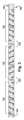
図1はガイドワイヤ100装置を示す。ガイドワイヤ100は、チューブ内腔104を画定し、長手方向に離間した近位および遠位本体端部106および108をそれぞれ有する細長いチューブ本体102を含む。チューブ本体102は、ステンレス鋼、ポリマー、ニチノール、他の適切な材料、またはそれらの任意の組み合わせで作ることができる。FIG. 1 illustrates a
コアワイヤ110は、図1Aに示されるように、チューブ内腔104の内側に少なくとも部分的に配置され得る。コアワイヤ110は、長手方向に離間した近位コアワイヤ端部112および遠位コアワイヤ端部114をそれぞれ有する。コアワイヤ110は、ステンレス鋼、ポリマー、ニチノール、任意の他の適切な材料、またはそれらの任意の組み合わせで作ることができる。The
再び図1Aに示すように、外側コイル116は、チューブ本体102を遠位チューブ端部108に隣接して少なくとも部分的に取り囲むことができる。外側コイル116は、ステンレス鋼、ポリマー、ニチノール、任意の他の適切な材料、またはそれらの任意の組み合わせで作ることができる。外側コイル116は、接着剤、溶接、摩擦嵌合などによってチューブ本体102に固定することができる。As shown again in FIG. 1A, the
図2に示すように、チューブ本体102は、それに沿って少なくとも1つの第1方向の螺旋状切り込みを有する第1の長手方向付勢部118と、少なくとも1つの第2方向の螺旋状切り込みを有する第2の長手方向付勢部120とを含む。第1の方向は、半径方向で第1の方向と反対である。すなわち、螺旋状切り込みの回転の「巻き方」または「向き」は、本明細書では「半径方向に反対」と呼ばれる第1および第2の方向で反対である。この「巻き方」の概念は、文脈によっては「キラリティ」としても知られている。As shown in FIG. 2, the
チューブ本体102に設けられ、それに沿って配置される第1および第2の長手方向付勢部118および120は、特定の使用環境に必要なだけ多くても少なくてもよい。第1および第2の長手方向付勢部118および120は、数および/または構成に関係なく、チューブストックの単一の一体部品から形成および/または別個のサブ部品のグループから組み立てることができる。第1および第2の長手方向付勢部118および120は、ガイドワイヤ100の柔軟性および回転可能性のうちの少なくとも1つを支援するために提供される。異なる数の第1および第2の長手方向付勢部118および120が単一のガイドワイヤ100に設けられる場合、ガイドワイヤ100は特定の方向に操縦するように付勢され、これはいくつかの使用環境では望ましい。第1および第2の長手方向付勢部118および120は、互いに対して長手方向に離間されてもよく、またはチューブ本体102に沿って実質的に隣接して切断されてもよい。The first and second
図2に示されるように、遷移長手方向部122は、第1および第2の長手方向付勢部118および120のうちの選択されたもの(隣接するものであってもよい)の間に長手方向に挿入することができ、遷移長手方向部はそれに沿って螺旋状切り込みを含まない。第1の付勢長手方向部118、第2の付勢長手方向部120、および遷移長手方向部122は、特定の使用環境の必要に応じて、任意の所望の長さであり、チューブ本体102に沿った任意の場所に配置することができる。第1および第2の長手方向付勢部118および120のピッチは、同じ第1および/または第2の長手方向付勢部118および120内で、または異なる第1および/または第2の長手方向付勢部118および120の間で変えることができ、ガイドワイヤ100により多くの柔軟性(より狭いピッチ/隣接するターン間の短いスパン)またはより少ない柔軟性(より緩いピッチ/隣接するターン間のより長いスパン)を提供する。As shown in FIG. 2, the transition
図3に目を向けると、少なくとも1つの電子部品324が、少なくとも部分的にチューブ内腔104内に配置され得る。電子部品324は、センサ(位置、温度、および圧力を含むがこれらに限定されない物理的特性用)、電磁コイルセンサ、トランスデューサ、または他の信号生成デバイス(限定されないが、RFまたはBluetooth送受信機)、その他のタイプの電子部品、またはそれらの任意の組み合わせであってもよい。一例では、1つ以上の電子部品324は、カナダ、オンタリオ州ウォータールーにあるNorthern Digital Inc.から市販されているAurora電磁追跡システムの場発生器によって提供されるような、電磁場に応答して複数の自由度(DOF)を感知するように構成された電磁センサ(例えば、センサコイル)である。DOF感知電子部品324は、センサ自体が空間内の位置を判定するか、またはセンサがセンサの位置を判定するために外部プロセッサに電気信号を提供するかに関係なく、本明細書では「追跡センサ」と呼ばれる。一例では、電子部品324は場発生器からの電磁場に応答して電気信号(例えば、電流)を提供する導電性コイルを含む5または6DOF追跡センサである。Turning to FIG. 3, at least one
各電子部品324は、存在する場合、図4に示すように、コアワイヤ110に沿って所定の取り付け領域426に取り付けることができる。所定の取り付け領域426は、図4Aの断面概略図に示されるように、コアワイヤ110の縮小された直径および/または少なくとも部分的に平坦化された部分であり得る。例えば、電子部品324がコアワイヤ110に接着または他の方法で取り付けられる場合、コアワイヤ110が比較的平坦な「プラトー」部分428を有する(すなわち、「平らな」)ことは、コアワイヤ110の湾曲した外周に接する実質的に平面の電子部品324を配置することと比較して、接着を補助することができる。任意の所望の量の平坦なプラトー部分428を含む1つ以上の所定の取り付け領域426は、コアワイヤ110に沿った任意の所望の位置に配置することができ、必須ではないが、他の所定の取り付け領域とコアワイヤ110の周囲の周りに半径方向に整列してもよい。いくつかの使用環境では、選択された所定の取り付け領域426に電子部品324は一時的または永続的に存在しない場合があり、または選択された電子部品324は、ガイドワイヤ100の異なる実装のために異なる所定の取り付け領域426に配置されてもよい。他の例では、電子部品324は、チューブ本体102の内部側壁に取り付けられるか、またはコアワイヤ110とチューブ本体との間に取り付けられるなど、チューブ内腔104内の他の位置に取り付けられてもよい。Each
図5~図6に示すように、少なくとも1つの信号ワイヤ628(2つが示されている)は、電子部品324との間で通信および/または電力信号を搬送するために提供され得る。各信号ワイヤ628は、電子部品324と電気的に結合された遠位信号ワイヤ部と、近位コアワイヤ端部112に隣接して配置された近位信号ワイヤ部530とを有する。近位信号ワイヤ部530は、チューブ内腔104の内側および外側に同時に横方向に部分を有するU字形接続部632を含む。「横」方向は、本明細書では、ガイドワイヤ100の縦軸の中心軸に向かう方向および中心軸から離れる方向を指すために使用される。近位信号ワイヤ部530の終端部634は、図6に示されるように、チューブ本体102の外面に取り付けられる。各信号ワイヤ628の長さは、その長さに沿った絶縁材料(例えば、プラスチックまたはゴム状ポリマー)の被覆を含んでもよい5-6, at least one signal wire 628 (two shown) may be provided to carry communication and/or power signals to and from the
別の言い方をすれば、信号ワイヤ628は、コアワイヤ110とチューブ内腔104の内壁との間の空間で電子部品324から近位に延びる。信号ワイヤ628は、環状空間内で自由に浮いていてもよく、または1つ以上の隣接する構造に(例えば、コアワイヤまたは内部側壁に)接続されていてもよい。一例では、信号ワイヤ628は、その長さに沿って螺旋状またはスパイラル状に巻かれるなど、コアワイヤの周りに巻かれる。近位信号ワイヤ部530が近位本体端部106に到達すると、信号ワイヤ628は、図6に示すように、チューブ内腔104から周囲空間まで「巻き付けられ」、近位本体端部106の最も近位の面の周りで「ヘアピン」ターンを行う。Stated another way, the
次に、近位信号ワイヤ部530の終端部634は、導電性カラー536によってチューブ本体102の外面に対して圧縮され得る。圧縮は、近位信号ワイヤ部530を所定の位置に機械的に維持することを意図した「圧着」であり得、または機械的接続よりも電気的接続であり得る。導電性カラー536は、チューブ本体102の円周の一部または全部の周りに延びることができ、銅、銀、鋼、または任意の他の所望の導電性材料で少なくとも部分的に構成することができるが、導電性カラー536の少なくとも一部は、ほとんどの使用環境に対して導電性である。The
図5に示すように、複数の導電性カラー536を設けることができ、各導電性カラー536は、それぞれの信号ワイヤ628との信号通信のために関連付けられる。選択された導電性カラー536に信号を誤って伝達しないように、付近の他の信号ワイヤ(その選択された導電性カラー536の下を別の導電性カラー536に向かって通過するものなど)を絶縁することができる。例えば、各信号ワイヤ628は、電子部品324および導電性カラー536の両方と同時に電気的に接続するために、それぞれの端部で(例えば、剥離によって)その絶縁カバーから解放されてもよい。As shown in FIG. 5, a plurality of
別の例では、電子部品324は、外部デバイスまたはシステムと通信するためのワイヤレス送信機、受信機、または送受信機を含むことができる。そのような実装では、少なくとも1つの信号ワイヤが構造から省略され得る。In another example,
特に図6に示されるようなさらなる例では、少なくとも1つの絶縁スペーサ642が、隣接する導電性カラー536の間、または単一の導電性カラー536に隣接して提供され得る。隣接する導電性カラー536間の電気的絶縁を提供することに加えて、スペーサは、より大きな直径の導電性カラー536が周期的に存在するために、階段状の外形を有する代わりに、実質的に一定の外形をガイドワイヤ100に提示することもできる。絶縁スペーサ642は、存在する場合、チューブ内腔104の外側に位置する近位信号ワイヤ部530の領域を保護するのにも役立ち得る。ガイドワイヤ100の外面は、特定の使用環境に必要な任意のコーティング(例えば潤滑性コーティング)および/または外部シース構成要素を含み得ることも考えられる。In a further example, particularly as shown in FIG. 6, at least one insulating
特定の使用環境に適したガイドワイヤに提供される任意の所望のシール、ガスケット、コネクタ、および/または他の構成要素も存在し得、例えば、耐久性手頃な価格、滅菌可能性、製造の容易さ、および/または任意の他の所望の要因またはそれらの組み合わせを考慮して、当業者によって容易に提供され得る。There may also be any desired seals, gaskets, connectors, and/or other components provided on the guidewire that are suitable for a particular environment of use and may be readily provided by one of ordinary skill in the art, taking into consideration, for example, durability, affordability, sterilizability, ease of manufacture, and/or any other desired factors or combinations thereof.
導電性カラー536は、任意の所望の理由のために任意の所望の構成を使用して、近位信号ワイヤ部530と、638で概略的に示される外部ガイドワイヤ制御システムとの間で電気信号を選択的に伝達するように構成される。例えば、640で概略的に示されるシステムコネクタは、システムコネクタ640に対する導電性カラー536(したがって、ガイドワイヤ100の残りの構成要素)の回転を可能にするために、「スリップリング」タイプの方法で使用され得る。このスリップリング動作は、ガイドワイヤ100の操作中に遭遇する通常の回転運動中の電子部品324との信号通信の損失を回避するのに役立ち得る。
一例として、システムコネクタ640は、信号ワイヤ628を外部デバイスに電気的に接続するためのインタフェースを提供する。部品がセンサである例では、外部デバイスは、センサからの信号を増幅およびデジタル化するように構成された回路を含むことができる。増幅されデジタル化された信号は、デバイスから、アプリケーション要件に従って信号を処理するように構成された制御ユニットに伝達されてもよい。一例では、制御ユニットは、電磁場発生装置からコイルセンサに誘導された信号に基づいてコイルセンサの位置および向きを計算し、計算されたデータを追加処理のためにコンピュータに提供するように構成される。他の例では、他のタイプとは異なるタイプの信号処理および分析が、外部の電子機器およびコンピューティングシステムによって実装され得る。In one example, the
図7は、上で説明され、一般的に図6に示される構成の例示的な実装を概略的に示す。図7では、図1~図6のガイドワイヤ100が、手術ナビゲーションシステム744に組み込まれたものとして示されている。図7では、外部通信デバイス(前述の外部デバイス、制御ユニット、および/またはガイドワイヤ制御システム638を組み込み、および/または関連付けることができる)が、746で概略的に示されている。外部通信デバイスは、電子部品324と通信する。一例では、通信デバイスは、「稲妻」記号によって表されるように、少なくとも1つの電子部品324(例えば、追跡センサ)と無線で通信する。別の例では、環状コネクタ640、例えばスリップリングを上記のように追加または代わりに使用して、図7においてそれらの間の破線によって表されているように、外部通信デバイス746と少なくとも1つの電子部品324との間のそれぞれの通信リンクを介して任意の所望のタイプの信号を通過させることができる。他の例では、各電子部品324と外部通信デバイス746との間の通信は、物理リンク(例えば、導電性または光リンク)を介して行うことができる。7 illustrates an exemplary implementation of the configuration described above and generally shown in FIG. 6. In FIG. 7, the
さらなる例として、ナビゲーションシステム744は、米国特許出願公開第2014/0276002号に開示されたナビゲーションシステムと同様に実施され、これは、参照により本明細書に組み込まれる。例えば、ナビゲーションシステム744は、電磁場を提供する場発生器を含む追跡システムとして実施される通信デバイス746を含む。追跡システムは、本明細書で説明するように、通信リンク(例えば、物理的または無線リンク)を介して電子部品(例えば、追跡センサ)324に結合される。一例では、追跡システム746は、ガイドワイヤ100の1つ以上の導電性カラー536に電気的に結合されて、場発生器によって生成された電磁場に応答する追跡センサからの電気信号(例えば、電流)を受信する。別の例では、追跡システムは、追跡システムによって感知される場を生成する信号を、通信リンクを介して追跡センサに提供することができる。追跡システム746は、追跡センサからの電気信号に応答して、追跡システムの3次元座標系における追跡センサの位置および向きを決定するように構成される。As a further example, the
したがって、ナビゲーションシステム744は、患者の解剖学的形状(例えば、主要な血管などの患者の脈管構造の形状を含む)およびガイドワイヤ100の1つ以上の3次元ユーザー認識可能仮想表示をリアルタイムで生成して、患者の解剖学的構造に対するガイドワイヤ100の手術中の位置決めを容易にすることができる。ガイドワイヤ100は、ナビゲーションシステム746のディスプレイ上で追跡および視覚化されている物体の例に対応する。Thus,
例えば、ガイドワイヤ100は、上で援用された米国特許出願公開第2014/0276002号に開示されているような術中の位置決めを可能にするシステムと組み合わせて利用されてもよい。ガイドワイヤ100は、3次元空間におけるセンサおよびガイドワイヤの位置および向きを追跡し、任意の方法で、ユーザー認識可能形式で1つ以上の出力視覚化を生成するために使用される電磁部品324(例えば、追跡センサ)を含み得る。For example, guidewire 100 may be utilized in combination with a system that enables intraoperative positioning, such as that disclosed in U.S. Patent Application Publication No. 2014/0276002, incorporated above.
一例では、外部通信デバイス746は、センサ信号を受信するために追跡センサ(すなわち、電子部品324)と電気的に結合されてもよく、手術ナビゲーションシステム744は、センサ信号に応答して追跡センサの位置および向きのうちの少なくとも1つのユーザー認識可能インジケーションを生成する。In one example, the
本明細書で使用されるとき、単数形「a」、「an」、および「the」は、文脈が明確に別段の指示をしない限り、複数形も含むことができる。本明細書で使用される「含む(comprises)」および/または「備える(comprising)」という用語は、記載された特徴、ステップ、操作、要素、および/または構成要素の存在を特定することができるが、1つ以上の他の特徴、ステップ、操作、要素、部品、および/またはそれらのグループの存在または追加を排除しないことがさらに理解されるであろう。As used herein, the singular forms "a," "an," and "the" can include the plural forms unless the context clearly dictates otherwise. It will be further understood that the terms "comprises" and/or "comprising" as used herein can specify the presence of stated features, steps, operations, elements, and/or components, but do not exclude the presence or addition of one or more other features, steps, operations, elements, components, and/or groups thereof.
本明細書で使用される場合、「および/または」という用語は、関連する列挙項目の1つ以上の任意およびすべての組み合わせを含むことができる。As used herein, the term "and/or" may include any and all combinations of one or more of the associated listed items.
本明細書で使用される場合、「XーY」、「XとYの間」および「約XとYの間」などの語句および/または図面ラベルは、XおよびYを含むと解釈することができる。As used herein, phrases and/or drawing labels such as "X-Y," "between X and Y," and "between about X and Y" can be construed to include X and Y.
本明細書で使用される場合、「約XとYの間」などの語句および/または図面ラベルは、「約Xと約Yの間」を意味し得る。As used herein, phrases such as "between about X and Y" and/or drawing labels may mean "between about X and about Y."
本明細書で使用される場合、「約XからYまで」などの語句および/または図面ラベルは、「約Xから約Yまで」を意味し得る。As used herein, phrases such as "from about X to Y" and/or drawing labels may mean "from about X to about Y."
ある要素が別の要素に対して「上にある」、「取り付けられている」、「接続されている」、「結合されている」、「接触している」「隣接している」などと呼ばれる場合、それは、他の要素または介在要素に対して、直接的に、上にあり、取り付けられ、接続され、結合され、または隣接している場合が存在し得ることができることが理解されよう。対照的に、要素が、例えば、別の要素に対して「直接上にある」、「直接取り付けられている」、「直接接続されている」、「直接結合されている」、または「直接接触している」、「直接隣接している」などと呼ばれる場合、介在要素は存在しない。他の特徴に「直接隣接して」配置される構造、または特徴への参照が、隣接する特徴と重なり合うか、またはその下にある部分を有し得るが、他の特徴に「隣接して」配置される構造、または特徴は、隣接する特徴と重なるか、またはその下にある部分を有していない可能性があることも、当業者には明らかであろう。It will be understood that when an element is referred to as being "on," "attached," "connected," "coupled," "in contact," "adjacent," etc., to another element, it may be directly on, attached, connected, coupled, or adjacent to the other element or to an intervening element. In contrast, when an element is referred to as being, for example, "directly on," "directly attached," "directly connected," "directly coupled," "in direct contact," "directly adjacent," etc., to another element, there is no intervening element. It will also be apparent to one skilled in the art that while a reference to a structure or feature that is "directly adjacent" to another feature may have portions that overlap or underlie the adjacent feature, a structure or feature that is "adjacent" to another feature may not have portions that overlap or underlie the adjacent feature.
「下(under)」、「下(below)」、「下(lower)」、「上(over)」、「上(upper)」、「近接(proximal)」、「遠位(distal)」などの空間的に相対的な用語は、図に示されている、別の要素(複数可)、または特徴(複数可)に対する、1つの要素、または特徴の関係を記載するように、記載を容易にするために本明細書で使用され得る。空間的に相対的な用語は、図に示されている向きに加えて、使用中、または動作中のデバイスの異なる向きを包含することができることが、理解されよう。例えば、図中の装置が逆さにされた場合、他の要素または特徴の「下(under)」または「下(beneath)」と記載された要素は、他の要素または特徴の「上(over)」に配向されることになる。Spatially relative terms such as "under," "below," "lower," "over," "upper," "proximal," "distal," and the like may be used herein for ease of description to describe the relationship of one element or feature to another element(s) or feature(s) shown in the figures. It will be understood that the spatially relative terms can encompass different orientations of the device in use or operation in addition to the orientation shown in the figures. For example, if the device in the figures were inverted, an element described as "under" or "beneath" the other element or feature would be oriented "over" the other element or feature.
本明細書で使用される場合、「XおよびYのうちの少なくとも1つ」という語句は、X、Y、またはXとYの組み合わせを含むと解釈することができる。要素がXおよびYの少なくとも1つを有すると説明される場合、要素は、特定の時点で、X、Y、またはXとYの組み合わせを含む場合があり、その選択は時々変化する可能性がある。対照的に、「Xの少なくとも1つ」という語句は、1つ以上のXを含むと解釈できる。As used herein, the phrase "at least one of X and Y" can be interpreted as including X, Y, or a combination of X and Y. When an element is described as having at least one of X and Y, the element may contain, at a particular time, X, Y, or a combination of X and Y, and the selection may change from time to time. In contrast, the phrase "at least one of X" can be interpreted as including one or more Xs.
様々な要素を説明するように、本明細書では「第1の」、「第2の」などの用語が使用され得るが、これらの要素は、これらの用語によって限定されるべきではないことが理解されよう。これらの用語は、ある要素を別の要素と区別するためにのみ使用される。したがって、以下で説明する「第1の」要素は、本開示の教示から逸脱することなく「第2の」要素と呼ばれることもできる。動作(またはステップ)の順序は、特に明記されていない限り、特許請求の範囲、または図に提示される順序に限定されない。Although terms such as "first", "second" and the like may be used herein to describe various elements, it will be understood that these elements should not be limited by these terms. These terms are used only to distinguish one element from another. Thus, a "first" element described below can also be referred to as a "second" element without departing from the teachings of this disclosure. The order of operations (or steps) is not limited to the order presented in the claims or in the figures, unless otherwise specified.
この開示の態様は、上記の例示的な実施形態を参照して特に示され説明されてきたが、様々な追加の態様が企図され得ることが当業者によって理解されるであろう。例えば、装置を使用するための上記の特定の方法は単なる例示であり、当業者は、上記の装置、またはその部品を、本明細書に示され、説明されるものと実質的に同様の位置に置くための任意の数のツール、一連のステップ、または他の手段/オプションを容易に決定することができる。図面を明瞭に保つために、示されている重複する構成要素の特定のものには具体的に番号が付けられていないが、当業者は、番号が付けられた構成要素に基づいて、構成要素に関連付けられるべき要素番号を理解するであろう。番号のない部品、図中の要素番号の存在または不在のみによって、同様の構成要素間の区別が意図または暗示されることはない。記載されている構造、および構成要素はいずれも、任意の適切なストック、または特注の構成要素、および/または任意の適切な材料、または材料の組み合わせを伴う、これらの構成のいずれかで、単一の単体部品、もしくはモノリシック部品として一体的に形成されるか、または別々の副構成要素で構成されることができるが、選択された材料(複数可)は、多くの用途で生体適合性であるものとする。記載された構造、および部品のいずれも、特定の使用環境で所望されるように、使い捨て、または再利用可能であり得る。任意の部品は、その部品に関係する材料、構成、少なくとも1つの寸法などを示すように、ユーザー認識可能なマーキングで提供されことができ、ユーザー認識可能なマーキングは、特定の使用環境のためにユーザーが類似の部品の配列から1つの部品を選択することを潜在的に支援する。「所定の」状態は、操作されている構造が実際にその状態に到達する前の任意の時点で決定され得、「事前決定」は、構造が所定の状態に達する直前に行われる。「実質的に」という用語は、本明細書では、指定されたものであるが必ずしも完全ではない品質を示すために使用され、「実質的な」品質は、品質が劣っているアイテムの比較的小さな包含の可能性を認めている。本明細書に記載の特定の部品が、特定の幾何学的形状を有するものとして示されているが、本開示のすべての構造は、特定の用途に望ましい任意の適切な形状、サイズ、構成、相対関係、断面積、または任意の他の物理的特性を有し得る。一態様または構成を参照して記載される任意の構造または特徴は、他のすべての態様、および構成に関して説明したすべてのオプションを有するものとして、本明細書で論じられる態様および構成のそれぞれを記載することは非現実的であるため、単独で、または他の構造もしくは特徴と組み合わせて、他の任意の態様または構成に提供され得る。これらの特徴のいずれかを組み込んだデバイスまたは方法は、以下の特許請求の範囲、およびその均等物に基づいて決定されるように、本開示の範囲に含まれると理解されるべきである。While aspects of this disclosure have been particularly shown and described with reference to the above exemplary embodiments, it will be understood by those skilled in the art that various additional aspects may be contemplated. For example, the above specific methods for using the device are merely exemplary, and one skilled in the art can readily determine any number of tools, sequences of steps, or other means/options for placing the above device, or parts thereof, in a substantially similar position as shown and described herein. To maintain clarity in the drawings, certain of the overlapping components shown have not been specifically numbered, but one skilled in the art will understand the element numbers to be associated with the components based on the numbered components. No distinction between similar components is intended or implied solely by the presence or absence of unnumbered parts, element numbers in the drawings. Any of the structures and components described can be integrally formed as a single unitary or monolithic part, or composed of separate subcomponents, in any of these configurations, with any suitable stock or custom components, and/or any suitable material or combination of materials, although the selected material(s) shall be biocompatible in many applications. Any of the structures and components described may be disposable or reusable as desired in a particular use environment. Any component may be provided with user-recognizable markings to indicate the material, configuration, at least one dimension, etc. associated with the component, potentially aiding the user in selecting one component from an array of similar components for a particular use environment. The "predetermined" state may be determined at any time before the structure being manipulated actually reaches that state, with the "predetermination" occurring immediately prior to the structure reaching the predetermined state. The term "substantially" is used herein to indicate a quality that is specified, but not necessarily complete, with "substantial" quality acknowledging the possibility of a relatively small inclusion of items of lesser quality. Although certain components described herein are shown as having particular geometric shapes, all structures of the present disclosure may have any suitable shape, size, configuration, relative relationship, cross-sectional area, or any other physical characteristic desired for a particular application. Any structure or feature described with reference to one aspect or configuration may be provided in any other aspect or configuration, either alone or in combination with other structures or features, as it would be impractical to describe each of the aspects and configurations discussed herein as having all of the options described with respect to all other aspects and configurations. Devices or methods incorporating any of these features should be understood to be within the scope of the present disclosure, as determined based on the following claims and their equivalents.
他の態様、目的、および利点は、図面、開示、および添付の特許請求の範囲の検討から取得されることができる。Other aspects, objects, and advantages can be obtained from a study of the drawings, the disclosure, and the appended claims.
Claims (15)
Translated fromJapaneseチューブ内腔を画定し、長手方向に離間された近位および遠位本体端部を有する細長いチューブ本体であって、前記細長いチューブ本体は、前記細長いチューブ本体に沿って第1の方向に少なくとも1つの螺旋状切り込みを含む第1の長手方向付勢部、および、前記細長いチューブ本体に沿って第2の方向に少なくとも1つの螺旋状切り込みを含む第2の長手方向付勢部を含み、前記第2の方向は、前記第1の方向と半径方向に反対である、細長いチューブ本体と、
少なくとも部分的に前記チューブ内腔の内側に配置され、長手方向に離間された近位および遠位コアワイヤ端部を有するコアワイヤと、
前記チューブ内腔内に少なくとも部分的に配置された追跡センサと、
を備える、ガイドワイヤ。 A guidewire comprising:
an elongate tube body defining a tube lumen and having longitudinallyspaced proximal and distal body ends, theelongate tube body including a first longitudinal biasing portion including at least onehelical cutin a first direction along theelongate tube body, and a second longitudinal biasingportion including at least onehelical cutin a second direction along the elongate tube body, thesecond direction being radially opposite to the first direction;
a core wire disposedat least partially within the tube lumen and having longitudinallyspaced apart proximal and distal core wire ends;
a tracking sensor disposed at least partially within the tube lumen;
A guidewire comprising:
前記追跡センサは、前記コアワイヤの所定の取り付け領域に取り付けられる、請求項1に記載のガイドワイヤ。 the tracking sensoris an electromagnetic coil sensor;
The guidewire of claim 1, wherein the tracking sensor is attached to a predetermined attachment area of the core wire .
ガイドワイヤであって、
チューブ内腔を画定し、長手方向に離間された近位および遠位本体端部を有する細長いチューブ本体であって、前記細長いチューブ本体は、前記細長いチューブ本体に沿って第1の方向に少なくとも1つの螺旋状切り込みを含む第1の長手方向付勢部、および、前記細長いチューブ本体に沿って第2の方向に少なくとも1つの螺旋状切り込みを含む第2の長手方向付勢部を含み、前記第2の方向は、前記第1の方向と半径方向に反対である、細長いチューブ本体と、
少なくとも部分的に前記チューブ内腔の内側に配置され、長手方向に離間された近位および遠位コアワイヤ端部を有するコアワイヤと、
前記チューブ内腔内に少なくとも部分的に配置され、センサ信号を提供するように構成された追跡センサと、
を含む、ガイドワイヤと、
前記センサ信号を受信するために前記追跡センサに電気的に結合された通信デバイスと、を備える、手術ナビゲーションシステムであり、
前記手術ナビゲーションシステムは、ユーザー認識可能形式で1つ以上の出力視覚化を生成するように構成される、手術ナビゲーションシステム。 1. A surgical navigation system, comprising:
A guidewire comprising:
an elongate tube body defining a tube lumen and having longitudinallyspaced proximaland distal body ends, theelongate tube body including a first longitudinal biasing portion including at least onehelical cutin a first direction along the elongate tube body , and a second longitudinal biasingportion including at least onehelical cutin a second direction along the elongate tube body, thesecond direction being radially opposite to the first direction;
a core wire disposedat least partially within the tube lumen andhaving longitudinallyspaced apartproximal and distal core wire ends;
a tracking sensor disposed at least partially within the tube lumen and configured to provide a sensor signal;
A guidewire comprising:
a communication device electrically coupled to the tracking sensor to receive the sensor signal;
The surgical navigation system is configured to generate one or more output visualizations in a user-perceivable format.
増幅および/またはデジタル化された信号は、前記通信デバイスから制御ユニットに伝達され、前記制御ユニットは、アプリケーション要件に従って前記増幅および/またはデジタル化された信号を処理するように構成されており、かつ/または
前記通信デバイスは、電磁場発生装置から前記追跡センサ内に誘導されるセンサ信号に応答して、前記追跡センサの位置および向きを示すデータを計算し、計算されたデータを追加の処理のためにコンピュータに提供するように構成されており、前記コンピュータは、患者の解剖学的構造に対する前記ガイドワイヤの術中の位置決めを容易にするために、前記センサ信号に応答して、リアルタイムで患者の解剖学的形状および前記ガイドワイヤの少なくとも1つの3次元ユーザー認識可能仮想表示を生成するように構成されている、請求項11に記載の手術ナビゲーションシステム。 the communications device includes circuitry configured to amplify and/or digitize the sensor signal;
12. The surgical navigation system of claim 11, wherein the amplified and/or digitized signal is communicatedfrom the communication device to a control unit, the control unit configured to process the amplified and/or digitized signal according to application requirements; and/or the communication device is configured to calculate data indicative of a position and orientation of the tracking sensor in response to a sensor signal induced from an electromagnetic field generator into the tracking sensor and provide the calculated data to a computer for further processing, thecomputer being configured to generate in real time a three-dimensional user-perceivable virtual representation of at least one of the patient's anatomy and the guidewire in response to the sensor signal tofacilitate intraoperative positioning of the guidewire relative to the patient's anatomy.
前記近位信号ワイヤ部の終端部は、導電性カラーによって前記細長いチューブ本体の外面に対して圧縮され、前記導電性カラーは、前記近位信号ワイヤ部と外部ガイドワイヤ制御システムとの間で電気信号を選択的に伝達するように構成されている、請求項11に記載の手術ナビゲーションシステム。 at least one signal wire includes a distal signal wireportion in electrical communication with the tracking sensor and a proximal signal wireportion located adjacent a proximal core wire end, the proximal signal wire portion having a U-shaped connection having portions laterally simultaneously insideand outside the tube lumen, the terminal end of the proximal signal wire portion being attached to an outer surface of theelongate tube body; and/or
12. The surgical navigation system of claim 11, wherein a terminal end of the proximal signal wire portion is compressed against an outer surface of the elongate tube body by a conductive collar, the conductive collar configured to selectively transmit electrical signals between the proximal signal wire portion and an external guidewire control system.
Applications Claiming Priority (5)
| Application Number | Priority Date | Filing Date | Title |
|---|---|---|---|
| US202062971651P | 2020-02-07 | 2020-02-07 | |
| US62/971,651 | 2020-02-07 | ||
| US17/108,587US11642178B2 (en) | 2020-02-07 | 2020-12-01 | Guidewire |
| US17/108,587 | 2020-12-01 | ||
| PCT/US2021/016287WO2021158582A1 (en) | 2020-02-07 | 2021-02-03 | Guidewire |
Publications (2)
| Publication Number | Publication Date |
|---|---|
| JP2023531110A JP2023531110A (en) | 2023-07-21 |
| JP7540766B2true JP7540766B2 (en) | 2024-08-27 |
Family
ID=77176887
Family Applications (1)
| Application Number | Title | Priority Date | Filing Date |
|---|---|---|---|
| JP2022548462AActiveJP7540766B2 (en) | 2020-02-07 | 2021-02-03 | Guidewires |
Country Status (6)
| Country | Link |
|---|---|
| US (1) | US11642178B2 (en) |
| EP (1) | EP4100094A4 (en) |
| JP (1) | JP7540766B2 (en) |
| CN (1) | CN115697457A (en) |
| CA (1) | CA3167363A1 (en) |
| WO (1) | WO2021158582A1 (en) |
Families Citing this family (1)
| Publication number | Priority date | Publication date | Assignee | Title |
|---|---|---|---|---|
| JP2024048911A (en)* | 2022-09-28 | 2024-04-09 | 富士フイルムヘルスケア株式会社 | Guidewires |
Citations (5)
| Publication number | Priority date | Publication date | Assignee | Title |
|---|---|---|---|---|
| JP2005046603A (en) | 2003-07-17 | 2005-02-24 | Terumo Corp | Guide wire |
| JP2005512628A (en) | 2001-12-14 | 2005-05-12 | ボストン サイエンティフィック リミテッド | Relumenization method for occluded vessels using magnetic resonance guidance |
| US20110022026A1 (en) | 2009-07-21 | 2011-01-27 | Lake Region Manufacturing, Inc. d/b/a Lake Region Medical. Inc. | Methods and Devices for Delivering Drugs Using Drug-Delivery or Drug-Coated Guidewires |
| JP2013165926A (en) | 2012-02-17 | 2013-08-29 | Sumitomo Bakelite Co Ltd | Medical instrument |
| JP2015513998A (en) | 2012-05-07 | 2015-05-18 | セント・ジュード・メディカル・エイトリアル・フィブリレーション・ディヴィジョン・インコーポレーテッド | Medical device guidewire with spiral notch and coating |
Family Cites Families (38)
| Publication number | Priority date | Publication date | Assignee | Title |
|---|---|---|---|---|
| US5282478A (en) | 1991-08-21 | 1994-02-01 | Baxter International, Inc. | Guidewire extension system with coil connectors |
| US5313967A (en) | 1992-07-24 | 1994-05-24 | Medtronic, Inc. | Helical guidewire |
| US6428489B1 (en) | 1995-12-07 | 2002-08-06 | Precision Vascular Systems, Inc. | Guidewire system |
| US20030069522A1 (en)* | 1995-12-07 | 2003-04-10 | Jacobsen Stephen J. | Slotted medical device |
| US6156046A (en) | 1997-11-07 | 2000-12-05 | Prolifix Medical, Inc. | Methods and systems for treating obstructions in a body lumen |
| US9254143B2 (en) | 1998-02-25 | 2016-02-09 | Revascular Therapeutics, Inc. | Guidewire for crossing occlusions or stenoses having a shapeable distal end |
| US6102890A (en) | 1998-10-23 | 2000-08-15 | Scimed Life Systems, Inc. | Catheter having improved proximal shaft design |
| US20040143286A1 (en) | 2003-01-17 | 2004-07-22 | Johnson Eric G. | Catheter with disruptable guidewire channel |
| US20040215109A1 (en) | 2003-04-23 | 2004-10-28 | Pingleton Edward D. | Helical guidewire |
| US8277386B2 (en) | 2004-09-27 | 2012-10-02 | Volcano Corporation | Combination sensor guidewire and methods of use |
| DE602004010276D1 (en) | 2004-11-10 | 2008-01-03 | Creganna Technologies Ltd | Introducer catheter assembly for stents |
| CN101203265A (en) | 2005-06-20 | 2008-06-18 | 导管治疗有限公司 | Sleeve steering and reinforcement |
| US20070112371A1 (en) | 2005-11-14 | 2007-05-17 | Medtronic Vascular, Inc. | Embolic protection filter having compact collapsed dimensions and method of making same |
| US8292827B2 (en) | 2005-12-12 | 2012-10-23 | Boston Scientific Scimed, Inc. | Micromachined medical devices |
| US8758333B2 (en) | 2006-04-04 | 2014-06-24 | The Spectranetics Corporation | Laser-assisted guidewire having a variable stiffness shaft |
| AU2007269274A1 (en) | 2006-06-30 | 2008-01-10 | Atheromed, Inc. | Atherectomy devices and methods |
| US9339632B2 (en) | 2006-09-27 | 2016-05-17 | Boston Scientific Scimed, Inc. | Catheter shaft designs |
| US8460214B2 (en) | 2008-10-14 | 2013-06-11 | The Cleveland Clinic Foundation | Vascular guidewire system and method |
| WO2010102105A1 (en)* | 2009-03-06 | 2010-09-10 | Cook Incorporated | Reinforced rapid exchange catheter |
| US9943668B2 (en) | 2010-07-16 | 2018-04-17 | Sub3 Vascular, Llc | Guidewire and catheter system and method for treating a blood clot |
| KR101912960B1 (en)* | 2010-10-25 | 2018-10-29 | 메드트로닉 아르디언 룩셈부르크 에스에이알엘 | Catheter Appratuses having Multi-Electrode Arrays for Renal Neuromodulation and Associated Systems and Methods |
| CA2856519C (en)* | 2011-11-22 | 2020-11-03 | Ascension Technology Corporation | Tracking a guidewire |
| US9044575B2 (en) | 2012-10-22 | 2015-06-02 | Medtronic Adrian Luxembourg S.a.r.l. | Catheters with enhanced flexibility and associated devices, systems, and methods |
| CA2895165A1 (en) | 2012-12-18 | 2014-06-26 | Volcano Corporation | Transitional region having cuts and a skive for an imaging catheter |
| US20140187980A1 (en) | 2012-12-28 | 2014-07-03 | Volcano Corporation | Hypotube Sensor Mount for Sensored Guidewire |
| CN103961785A (en) | 2013-01-31 | 2014-08-06 | 朝日英达科株式会社 | Slitted pipe and guide wire using the same |
| JP2016513540A (en) | 2013-03-15 | 2016-05-16 | ザ クリーブランド クリニック ファウンデーションThe Cleveland ClinicFoundation | System that facilitates positioning and guidance during surgery |
| WO2015077328A1 (en) | 2013-11-22 | 2015-05-28 | Volcano Corporation | Sensor mounting assembly for sensored guidewire and associated devices, systems, and methods |
| US10625055B2 (en) | 2014-06-26 | 2020-04-21 | The Cleveland Clinic Foundation | Method and apparatus for tracking a position of a medical device |
| WO2016019028A1 (en) | 2014-07-29 | 2016-02-04 | Gregory Sullivan | Hypotube construction |
| US10617847B2 (en) | 2014-11-04 | 2020-04-14 | Orbusneich Medical Pte. Ltd. | Variable flexibility catheter support frame |
| WO2016116817A1 (en) | 2015-01-20 | 2016-07-28 | Vikas Gupta | High-torque guidewires and methods for making and using them |
| US10722139B2 (en) | 2015-02-16 | 2020-07-28 | Biosense Webster (Israel) Ltd. | Navigation of an angioplasty guidewire |
| US10391306B2 (en) | 2015-09-11 | 2019-08-27 | Pacesetter, Inc. | Tube-cut helical fixation anchor for electrotherapy device |
| US10391274B2 (en) | 2016-07-07 | 2019-08-27 | Brian Giles | Medical device with distal torque control |
| US20180228502A1 (en) | 2017-02-13 | 2018-08-16 | Penumbra, Inc. | Dual lumen hypotube catheter |
| US10835278B2 (en) | 2017-02-21 | 2020-11-17 | Boston Scientific Scimed, Inc. | Medical device systems and accessories |
| WO2019195287A1 (en) | 2018-04-02 | 2019-10-10 | Transmural Systems Llc | Helical guidewires and related systems |
- 2020
- 2020-12-01USUS17/108,587patent/US11642178B2/enactiveActive
- 2021
- 2021-02-03WOPCT/US2021/016287patent/WO2021158582A1/ennot_activeCeased
- 2021-02-03CNCN202180023213.4Apatent/CN115697457A/enactivePending
- 2021-02-03CACA3167363Apatent/CA3167363A1/enactivePending
- 2021-02-03JPJP2022548462Apatent/JP7540766B2/enactiveActive
- 2021-02-03EPEP21751443.9Apatent/EP4100094A4/enactivePending
Patent Citations (5)
| Publication number | Priority date | Publication date | Assignee | Title |
|---|---|---|---|---|
| JP2005512628A (en) | 2001-12-14 | 2005-05-12 | ボストン サイエンティフィック リミテッド | Relumenization method for occluded vessels using magnetic resonance guidance |
| JP2005046603A (en) | 2003-07-17 | 2005-02-24 | Terumo Corp | Guide wire |
| US20110022026A1 (en) | 2009-07-21 | 2011-01-27 | Lake Region Manufacturing, Inc. d/b/a Lake Region Medical. Inc. | Methods and Devices for Delivering Drugs Using Drug-Delivery or Drug-Coated Guidewires |
| JP2013165926A (en) | 2012-02-17 | 2013-08-29 | Sumitomo Bakelite Co Ltd | Medical instrument |
| JP2015513998A (en) | 2012-05-07 | 2015-05-18 | セント・ジュード・メディカル・エイトリアル・フィブリレーション・ディヴィジョン・インコーポレーテッド | Medical device guidewire with spiral notch and coating |
Also Published As
| Publication number | Publication date |
|---|---|
| CN115697457A (en) | 2023-02-03 |
| WO2021158582A1 (en) | 2021-08-12 |
| CA3167363A1 (en) | 2021-08-12 |
| EP4100094A1 (en) | 2022-12-14 |
| US11642178B2 (en) | 2023-05-09 |
| EP4100094A4 (en) | 2024-03-06 |
| US20210244483A1 (en) | 2021-08-12 |
| JP2023531110A (en) | 2023-07-21 |
Similar Documents
| Publication | Publication Date | Title |
|---|---|---|
| EP0928600B1 (en) | Steerable catheter with electromagnetic sensor | |
| JP6324718B2 (en) | Catheter with combined position and pressure sensing structure | |
| US8862204B2 (en) | Reducing mechanical stress on conductors and connection points in a position determinable interventional medical device | |
| EP1319364B1 (en) | Multiple electrode mapping catheter with location sensor | |
| JP5411444B2 (en) | Guide wire assembly | |
| EP1319365A2 (en) | Multiple electrode mapping catheter with improved expansion mechanism | |
| EP2209419B1 (en) | Sensor guide wire | |
| CN104271035A (en) | Medical device guidewire with helical cutout and coating | |
| CN103068332A (en) | Navigated malleable surgical instrument | |
| JP5746422B2 (en) | Sensor assembly secured within the catheter wall | |
| US10664008B2 (en) | Catheter-based system having dongle with shape memory | |
| JP7540766B2 (en) | Guidewires | |
| AU2019200908A1 (en) | Catheter with multifunctional microinjection-molded housing | |
| HK40080069A (en) | Guidewire | |
| US20250249215A1 (en) | Steerable sheath | |
| EP4147742A2 (en) | Sheath and catheter having means for controlling radial orientation thereof |
Legal Events
| Date | Code | Title | Description |
|---|---|---|---|
| A521 | Request for written amendment filed | Free format text:JAPANESE INTERMEDIATE CODE: A523 Effective date:20230623 | |
| A621 | Written request for application examination | Free format text:JAPANESE INTERMEDIATE CODE: A621 Effective date:20230623 | |
| A977 | Report on retrieval | Free format text:JAPANESE INTERMEDIATE CODE: A971007 Effective date:20240425 | |
| A131 | Notification of reasons for refusal | Free format text:JAPANESE INTERMEDIATE CODE: A131 Effective date:20240514 | |
| A521 | Request for written amendment filed | Free format text:JAPANESE INTERMEDIATE CODE: A523 Effective date:20240520 | |
| TRDD | Decision of grant or rejection written | ||
| A01 | Written decision to grant a patent or to grant a registration (utility model) | Free format text:JAPANESE INTERMEDIATE CODE: A01 Effective date:20240709 | |
| A61 | First payment of annual fees (during grant procedure) | Free format text:JAPANESE INTERMEDIATE CODE: A61 Effective date:20240807 | |
| R150 | Certificate of patent or registration of utility model | Ref document number:7540766 Country of ref document:JP Free format text:JAPANESE INTERMEDIATE CODE: R150 |