JP7540654B2 - WIRELESS POWER TRANSMISSION SYSTEM AND RESONANT FREQUENCY ADJUSTMENT UNIT FOR WIRELESS POWER TRANSMISSION SYSTEM - Google Patents
WIRELESS POWER TRANSMISSION SYSTEM AND RESONANT FREQUENCY ADJUSTMENT UNIT FOR WIRELESS POWER TRANSMISSION SYSTEMDownload PDFInfo
- Publication number
- JP7540654B2 JP7540654B2JP2022579347AJP2022579347AJP7540654B2JP 7540654 B2JP7540654 B2JP 7540654B2JP 2022579347 AJP2022579347 AJP 2022579347AJP 2022579347 AJP2022579347 AJP 2022579347AJP 7540654 B2JP7540654 B2JP 7540654B2
- Authority
- JP
- Japan
- Prior art keywords
- power transmission
- resonant frequency
- wireless power
- transmission system
- adjustment unit
- Prior art date
- Legal status (The legal status is an assumption and is not a legal conclusion. Google has not performed a legal analysis and makes no representation as to the accuracy of the status listed.)
- Active
Links
- 230000005540biological transmissionEffects0.000titleclaimsdescription133
- 230000005684electric fieldEffects0.000claimsdescription23
- 239000003990capacitorSubstances0.000claimsdescription11
- 238000010586diagramMethods0.000description23
- 229910052751metalInorganic materials0.000description12
- 239000002184metalSubstances0.000description12
- 239000000463materialSubstances0.000description7
- 241000700159RattusSpecies0.000description5
- 229910052782aluminiumInorganic materials0.000description5
- XAGFODPZIPBFFR-UHFFFAOYSA-NaluminiumChemical compound[Al]XAGFODPZIPBFFR-UHFFFAOYSA-N0.000description5
- 238000009429electrical wiringMethods0.000description3
- 238000009434installationMethods0.000description3
- 230000035699permeabilityEffects0.000description3
- XEEYBQQBJWHFJM-UHFFFAOYSA-NIronChemical compound[Fe]XEEYBQQBJWHFJM-UHFFFAOYSA-N0.000description2
- PXHVJJICTQNCMI-UHFFFAOYSA-NNickelChemical compound[Ni]PXHVJJICTQNCMI-UHFFFAOYSA-N0.000description2
- HCHKCACWOHOZIP-UHFFFAOYSA-NZincChemical compound[Zn]HCHKCACWOHOZIP-UHFFFAOYSA-N0.000description2
- XLOMVQKBTHCTTD-UHFFFAOYSA-NZinc monoxideChemical compound[Zn]=OXLOMVQKBTHCTTD-UHFFFAOYSA-N0.000description2
- 239000004020conductorSubstances0.000description2
- 239000010949copperSubstances0.000description2
- 230000000694effectsEffects0.000description2
- 230000014509gene expressionEffects0.000description2
- 238000012546transferMethods0.000description2
- 229910052725zincInorganic materials0.000description2
- 239000011701zincSubstances0.000description2
- 235000001674Agaricus brunnescensNutrition0.000description1
- 229910000952Be alloyInorganic materials0.000description1
- OKTJSMMVPCPJKN-UHFFFAOYSA-NCarbonChemical compound[C]OKTJSMMVPCPJKN-UHFFFAOYSA-N0.000description1
- RYGMFSIKBFXOCR-UHFFFAOYSA-NCopperChemical compound[Cu]RYGMFSIKBFXOCR-UHFFFAOYSA-N0.000description1
- 241001465754MetazoaSpecies0.000description1
- GWEVSGVZZGPLCZ-UHFFFAOYSA-NTitan oxideChemical compoundO=[Ti]=OGWEVSGVZZGPLCZ-UHFFFAOYSA-N0.000description1
- 230000003044adaptive effectEffects0.000description1
- 238000005452bendingMethods0.000description1
- 238000004891communicationMethods0.000description1
- 229910052802copperInorganic materials0.000description1
- 238000013461designMethods0.000description1
- 230000005672electromagnetic fieldEffects0.000description1
- 238000005516engineering processMethods0.000description1
- 238000011156evaluationMethods0.000description1
- 238000002474experimental methodMethods0.000description1
- 239000002360explosiveSubstances0.000description1
- 229910002804graphiteInorganic materials0.000description1
- 239000010439graphiteSubstances0.000description1
- AMGQUBHHOARCQH-UHFFFAOYSA-Nindium;oxotinChemical compound[In].[Sn]=OAMGQUBHHOARCQH-UHFFFAOYSA-N0.000description1
- 229910052742ironInorganic materials0.000description1
- 238000005259measurementMethods0.000description1
- 239000007769metal materialSubstances0.000description1
- 238000000034methodMethods0.000description1
- 239000000203mixtureSubstances0.000description1
- 238000012986modificationMethods0.000description1
- 230000004048modificationEffects0.000description1
- 229910052759nickelInorganic materials0.000description1
- 230000000149penetrating effectEffects0.000description1
- 239000011347resinSubstances0.000description1
- 229920005989resinPolymers0.000description1
- 239000010935stainless steelSubstances0.000description1
- 229910001220stainless steelInorganic materials0.000description1
- OGIDPMRJRNCKJF-UHFFFAOYSA-Ntitanium oxideInorganic materials[Ti]=OOGIDPMRJRNCKJF-UHFFFAOYSA-N0.000description1
- 239000011787zinc oxideSubstances0.000description1
Images


Classifications
- H—ELECTRICITY
- H01—ELECTRIC ELEMENTS
- H01Q—ANTENNAS, i.e. RADIO AERIALS
- H01Q15/00—Devices for reflection, refraction, diffraction or polarisation of waves radiated from an antenna, e.g. quasi-optical devices
- H01Q15/14—Reflecting surfaces; Equivalent structures
- H—ELECTRICITY
- H02—GENERATION; CONVERSION OR DISTRIBUTION OF ELECTRIC POWER
- H02J—CIRCUIT ARRANGEMENTS OR SYSTEMS FOR SUPPLYING OR DISTRIBUTING ELECTRIC POWER; SYSTEMS FOR STORING ELECTRIC ENERGY
- H02J50/00—Circuit arrangements or systems for wireless supply or distribution of electric power
- H02J50/005—Mechanical details of housing or structure aiming to accommodate the power transfer means, e.g. mechanical integration of coils, antennas or transducers into emitting or receiving devices
- H—ELECTRICITY
- H02—GENERATION; CONVERSION OR DISTRIBUTION OF ELECTRIC POWER
- H02J—CIRCUIT ARRANGEMENTS OR SYSTEMS FOR SUPPLYING OR DISTRIBUTING ELECTRIC POWER; SYSTEMS FOR STORING ELECTRIC ENERGY
- H02J50/00—Circuit arrangements or systems for wireless supply or distribution of electric power
- H02J50/10—Circuit arrangements or systems for wireless supply or distribution of electric power using inductive coupling
- H02J50/12—Circuit arrangements or systems for wireless supply or distribution of electric power using inductive coupling of the resonant type
- H—ELECTRICITY
- H02—GENERATION; CONVERSION OR DISTRIBUTION OF ELECTRIC POWER
- H02J—CIRCUIT ARRANGEMENTS OR SYSTEMS FOR SUPPLYING OR DISTRIBUTING ELECTRIC POWER; SYSTEMS FOR STORING ELECTRIC ENERGY
- H02J50/00—Circuit arrangements or systems for wireless supply or distribution of electric power
- H02J50/20—Circuit arrangements or systems for wireless supply or distribution of electric power using microwaves or radio frequency waves
- H—ELECTRICITY
- H02—GENERATION; CONVERSION OR DISTRIBUTION OF ELECTRIC POWER
- H02J—CIRCUIT ARRANGEMENTS OR SYSTEMS FOR SUPPLYING OR DISTRIBUTING ELECTRIC POWER; SYSTEMS FOR STORING ELECTRIC ENERGY
- H02J50/00—Circuit arrangements or systems for wireless supply or distribution of electric power
- H02J50/70—Circuit arrangements or systems for wireless supply or distribution of electric power involving the reduction of electric, magnetic or electromagnetic leakage fields
- H—ELECTRICITY
- H02—GENERATION; CONVERSION OR DISTRIBUTION OF ELECTRIC POWER
- H02J—CIRCUIT ARRANGEMENTS OR SYSTEMS FOR SUPPLYING OR DISTRIBUTING ELECTRIC POWER; SYSTEMS FOR STORING ELECTRIC ENERGY
- H02J50/00—Circuit arrangements or systems for wireless supply or distribution of electric power
- H02J50/90—Circuit arrangements or systems for wireless supply or distribution of electric power involving detection or optimisation of position, e.g. alignment
Landscapes
- Engineering & Computer Science (AREA)
- Computer Networks & Wireless Communication (AREA)
- Power Engineering (AREA)
- Physics & Mathematics (AREA)
- Electromagnetism (AREA)
- Transmitters (AREA)
Description
Translated fromJapanese本発明は、無線電力伝送システムおよび無線電力伝送システム用の共振周波数調整部に関する。具体的には、本発明は、高周波電磁波を送電する送電器を用いる無線電力伝送システムに関するものである。本発明の無線電力伝送システムは、倉庫内、工場内、車両内部など、壁面で囲まれた空間を利用するものであり、その空間のサイズや空間内に内包される物体に関わらず、あらかじめ任意に設定した周波数の電磁波を導入することで、無線電力を供給するための構造および電子機器に関する。The present invention relates to a wireless power transmission system and a resonant frequency adjustment unit for a wireless power transmission system. Specifically, the present invention relates to a wireless power transmission system that uses a power transmitter that transmits high-frequency electromagnetic waves. The wireless power transmission system of the present invention utilizes a space surrounded by walls, such as inside a warehouse, a factory, or the inside of a vehicle, and relates to a structure and electronic device for supplying wireless power by introducing electromagnetic waves of a frequency that is arbitrarily set in advance, regardless of the size of the space or the objects contained within the space.
近年、IOT(Internet of Things)デバイスの爆発的な増加に伴って、これらへの電力供給方法に課題が生じている。膨大なデバイスへの配線接続は困難であり、また、電池を電源とする場合には消耗した電池の交換に多大な労力を要する問題がある。これらを解決するために、無線にて電力を伝送する技術が期待されている。In recent years, the explosive increase in IOT (Internet of Things) devices has created problems with the methods of powering these devices. Wiring a huge number of devices is difficult, and when batteries are used as the power source, replacing worn-out batteries requires a lot of effort. To solve these problems, technology that transmits power wirelessly is expected.
非特許文献1には、金属で囲まれた空間内を共振器に見立て、共振器固有の共振周波数で送電部から電磁波を照射し、共振器内の受電器へ送電する無線電力伝送システムが開示されている。非特許文献1には、共振器のサイズおよび共振モードに対する共振周波数の関係が詳細に記載されている。Non-Patent
非特許文献2には、金属で囲まれた空間内を共振器に見立て、共振器固有の共振周波数で送電部から電磁波を照射し、共振器内の受電器へ送電する無線電力伝送システムが開示されている。非特許文献2には、共振器の内包物によって共振周波数が変化する旨の記載がある。Non-Patent
従来の無線電力伝送システムでは、導電体で包囲された空間を共振器に見立て、共振器の寸法と共振モードによって決定される共振周波数に設定した電磁波を利用して、無線電力伝送が行われている。従って、無線電力伝送システムは、共振器のサイズに応じて利用周波数が異なり、送電部の回路をそのつど設計し直さなければならない課題があった。In conventional wireless power transmission systems, the space surrounded by conductors is treated as a resonator, and wireless power transmission is carried out using electromagnetic waves set at a resonant frequency determined by the dimensions and resonant mode of the resonator. Therefore, in wireless power transmission systems, the frequency used varies depending on the size of the resonator, and there was an issue that the circuit of the power transmission section had to be redesigned each time.
例えば、非特許文献1では、共振器の大きさと共振モードに対する共振周波数の関係が詳細に記載されている。ここから、共振モード、すなわち共振器内の電磁界分布を決定すると、共振器の大きさに対応して共振周波数が一義的に決定されることがわかる。しかし、無線電力伝送システムが利用される空間の大きさは、利用の目的や環境によって異なるため、送電周波数はその環境ごとに調整を余儀なくされる。従って、送電部の回路は、利用環境ごとにひとつひとつ異なる設計を採用する必要があり、工業的に望ましくない。For example, Non-Patent
また、高い電力伝送効率を実現するためには、共振器内に存在する物体の大きさや形状や個数や材質に応じて、送電器から送信する電磁波の周波数を調整する必要がある。そのため、送電部の回路構成が複雑となるほか、送電部のインピーダンス不整合が生じる課題がある。In addition, to achieve high power transmission efficiency, it is necessary to adjust the frequency of the electromagnetic waves transmitted from the power transmitter according to the size, shape, number, and material of the objects present inside the resonator. This makes the circuit configuration of the power transmission unit complex, and also poses the problem of impedance mismatch in the power transmission unit.
例えば、非特許文献2では、金属製空洞共振器内に閉じ込めたラットに取り付けられた受電器に対して、電磁波を介して無線電力伝送を行う検討がなされている。非特許文献2の筆者らは、ラットを閉じ込める前の共振器固有の共振周波数が実測値および計算値ともに346.6MHzであったのに対し、ラットを閉じ込めた後の共振周波数が335.0MHzに変化していることを、上記文献中で明らかにしている。この共振周波数の変化はラットの体を構成する物質の比誘電率が空気とは異なることに起因するものである。すなわちラットに限らず、共振器の中に空気とは異なる材質からなる物体を入れることによって、共振周波数は変化することとなる。For example, in Non-Patent
工場や倉庫などの空間を共振器と見立て、実使用環境でのIOTデバイスへの無線電力伝送するシステムを想定したとき、共振器内のIOTデバイスの配置や、その他の物体の配置は必ずしも一定とは限らない。すなわち共振周波数はその時々で変化すると予想される。送電器から送信される電磁波の周波数は、共振器の共振周波数と合致させる必要があるため、前述の使用環境では、共振器の共振周波数を適宜検出し、適切な周波数に調整しながら送電する複雑な回路を構築しなければならない課題がある。When considering a system for wireless power transmission to an IOT device in a real usage environment, with a space such as a factory or warehouse as a resonator, the arrangement of the IOT device in the resonator and the arrangement of other objects are not necessarily constant. In other words, the resonant frequency is expected to change from time to time. Since the frequency of the electromagnetic waves transmitted from the power transmitter needs to match the resonant frequency of the resonator, in the above-mentioned usage environment, there is a challenge in constructing a complex circuit that detects the resonant frequency of the resonator as appropriate and transmits power while adjusting it to the appropriate frequency.
加えて、共振器と送電部のインピーダンス整合は周波数ごとに最適条件が変化するため、送電に使用する周波数が変化すると、整合回路と共振器との間でインピーダンス不整合が生じ、送電効率が低下する課題がある。In addition, since the optimal conditions for impedance matching between the resonator and the power transmission unit change for each frequency, when the frequency used for power transmission changes, an impedance mismatch occurs between the matching circuit and the resonator, resulting in a decrease in power transmission efficiency.
本発明は、上記課題を解決するためになされたものであり、共振器の大きさに関わらず、あるいは、共振器内の物体の配置、個数、材質に関わらず、送電周波数を変化させる必要のない無線電力伝送システムを提供することを目的とする。さらに、本発明は、上記無線電力伝送システム用の共振周波数調整部を提供することを目的とする。The present invention has been made to solve the above problems, and aims to provide a wireless power transmission system that does not require changing the transmission frequency regardless of the size of the resonator or the arrangement, number, or material of objects in the resonator. Furthermore, the present invention aims to provide a resonant frequency adjustment unit for the wireless power transmission system.
本発明に係る無線電力伝送システムは、適宜な導電率および周波数選択性を有する電磁波遮蔽部材によって全体が包囲された構造体と、少なくとも1つの受電部と、少なくとも1つの送電部と、少なくとも1つの共振周波数調整部と、を備え、上記共振周波数調整部は、開放端を有する少なくとも1つの導電性突起部と、上記導電性突起部の開放端でない他端に接続されている伝送線路と、を備え、上記導電性突起部の開放端は、上記構造体の内側に配置され、上記導電性突起部との接続部ではない上記伝送線路の他端は、上記構造体の壁面をなす上記電磁波遮蔽部材と電気的に接続されている。The wireless power transmission system of the present invention comprises a structure entirely surrounded by an electromagnetic wave shielding member having appropriate conductivity and frequency selectivity, at least one receiving unit, at least one transmitting unit, and at least one resonant frequency adjustment unit, the resonant frequency adjustment unit comprising at least one conductive protrusion having an open end and a transmission line connected to the other end other than the open end of the conductive protrusion, the open end of the conductive protrusion being disposed inside the structure, and the other end of the transmission line which is not the connection part with the conductive protrusion being electrically connected to the electromagnetic wave shielding member forming a wall surface of the structure.
本発明に係る無線電力伝送システム用の共振周波数調整部は、適宜な導電率および周波数選択性を有する電磁波遮蔽部材によって全体が包囲された構造体と、少なくとも1つの受電部と、少なくとも1つの送電部とを備える無線電力伝送システム用の共振周波数調整部であって、上記共振周波数調整部は、上記構造体の内側に配置するための開放端を有する少なくとも1つの導電性突起部と、上記導電性突起部の開放端でない他端に接続されている伝送線路であり、上記導電性突起部との接続部ではない他端を、上記構造体の壁面をなす上記電磁波遮蔽部材と電気的に接続するための伝送線路と、を備える。The resonant frequency adjustment unit for a wireless power transmission system according to the present invention is a resonant frequency adjustment unit for a wireless power transmission system comprising a structure entirely surrounded by an electromagnetic wave shielding member having appropriate conductivity and frequency selectivity, at least one receiving unit, and at least one transmitting unit, wherein the resonant frequency adjustment unit comprises at least one conductive protrusion having an open end for placement inside the structure, and a transmission line connected to the other end other than the open end of the conductive protrusion, and for electrically connecting the other end other than the connection part with the conductive protrusion to the electromagnetic wave shielding member forming the wall surface of the structure.
本発明によれば、導電性突起部および伝送線路を備える共振周波数調整部を利用することによって、共振器の大きさに関わらず、あるいは、共振器の内部に存在する物体に関わらず、一定の共振周波数を利用して無線電力伝送を行うことができる。According to the present invention, by utilizing a resonant frequency adjustment unit having a conductive protrusion and a transmission line, wireless power transmission can be performed using a constant resonant frequency regardless of the size of the resonator or regardless of the object present inside the resonator.
以下、本発明の実施形態について図面を参照しながら説明する。Below, an embodiment of the present invention is described with reference to the drawings.
本明細書において、要素間の関係性を示す用語(例えば「垂直」、「平行」、「直交」など)、および、要素の形状を示す用語は、厳格な意味のみを表す表現ではなく、実質的に同等な範囲、例えば数%程度の差異をも含むことを意味する表現である。In this specification, terms indicating the relationship between elements (e.g., "vertical," "parallel," "orthogonal," etc.) and terms indicating the shape of elements are not expressions that only express a strict meaning, but are expressions that also include a range of substantial equivalence, for example, differences of a few percent.
図1は本発明に係る無線電力伝送システムの一例の構成図である。図1において、無線電力伝送システム1は、適宜な導電率および周波数選択性を有する電磁波遮蔽部材2によって全体が包囲された構造体を共振器に見立て、その内部に、少なくとも1つの受電部3と、少なくとも1つの送電部4とを備え、さらに、上記構造体に少なくとも1つの共振周波数調整部5を備える。すなわち、無線電力伝送システム1は無線電力伝送を実現する構造物の全体を指している。なお、構造体の形状は直方体形状に限定されるものではなく、例えば、ZX面が五角形である五角柱形状、ZX面が台形である四角柱形状、ZX面が半円である半円柱形状などであってもよい。1 is a diagram showing an example of a wireless power transmission system according to the present invention. In FIG. 1, the wireless
電磁波遮蔽部材2は導電性を有していれば特に限定されないが、好ましくは銅、アルミニウム、鉄、ステンレス、ニッケルなどの金属材料が挙げられる。あるいは、酸化亜鉛、酸化チタン、酸化インジウムスズ(ITO)などの導電性酸化物材料、グラファイト、有機導電材料などが挙げられる。これらは上記部材からなる複数の層で構成されてもよい。また、導電性を有していれば合金または混合物であっても構わない。加えて、電力供給する周波数において電磁波遮蔽部材として動作するのであれば、形状は板状、メッシュ状、膜状、ポーラス状などであってもよい。なお、電磁波遮蔽部材2は、無線電力伝送に供する周波数に対してのみ電磁波遮蔽機能を有していればよく、例えば無線通信用の周波数に対しては電磁波透過能を持ってもよい。すなわち、適宜な周波数選択性を有していればよい。The electromagnetic
受電部3は受電器6からなる。受電器6の構成について図2Aおよび図2Bを用いて説明する。受電器6は、例えば、アンテナとなる電気配線部7または9と、整流回路8とから構成される。必要に応じてスイッチ、整合回路等を取り付けてもよい。アンテナは代表的にはダイポールアンテナ7、ループアンテナ9などが適している。ダイポールアンテナ7は適宜折り曲げてもよい。また、グラウンドあるいは受電部3の基準電位となる部分に配線の一部を短絡させた逆F型構造を採用してもよい。アンテナ配線の一部にキャパシタまたはインダクタを挿入することで対応周波数を調整することも可能である。これらは、電磁波遮蔽部材2で形成される共振器に由来した共振周波数に応じて、適切に選択される。The
送電部4の構成について図3を用いて説明する。送電部4は、送電器10と整合回路11と高周波電源12とからなる。整合回路11は、送電器10と高周波電源12の間に接続される。整合回路11はあらかじめ設定された送電周波数において共振器とインピーダンス整合を取るように調整されている。The configuration of the
送電器10の構成について図4を用いて説明する。送電器10は、例えば、金属棒13とそれに垂直方向に配置された送電アンテナ配線14とからなる。金属棒13は電磁波遮蔽部材2に対して概ね垂直に設置されることが好ましい。このとき、金属棒13は、電磁波遮蔽部材2と電気的に接触しないように設置されつつ、電磁波遮蔽部材2を貫通して共振器(構造体)の外側に設置された整合回路11に電気的に接続される。なお、整合回路11および高周波電源12の基準電位と電磁波遮蔽部材2の基準電位がほぼ同じである場合、接続に当たってはSMA(Sub Miniature Type A)端子などのコネクタを適宜介してもよい。整合回路11および高周波電源12の基準電位と電磁波遮蔽部材2の基準電位が異なる場合、受電器6と同じようにダイポールアンテナ(図示せず)またはループアンテナ(図示せず)を用いることで同等の効果を得ることができる。送電アンテナ配線14はプリント基板などの上に配線してもよいが、金属棒13を折り曲げて配線としても構わない。また、送電アンテナ配線14は配線される面内において適宜折り曲げてもよい。送電アンテナ配線14は、電界を用いて送電する場合は電磁波遮蔽部材2からなる共振器の壁面に対して概ね平行に、磁界を用いて送電する場合は電磁波遮蔽部材2からなる共振器の壁面に対して概ね垂直に形成されることが好ましい。The configuration of the
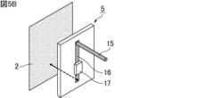
共振周波数調整部5の構成について図5A、図5Bおよび図5Cを用いて説明する。共振周波数調整部5は導電性突起部15と伝送線路16とからなる。導電性突起部15の開放端は共振器(構造体)の内側に配置されている。ここで突起とは、電磁波遮蔽部材2よりも共振器の内側に向けて開放端を突き出した形状であることを指しており、その形状はロッド状、ワイヤー状、傘状、マッシュルーム状、円錐状、角錐状、ループ状などであってもよい。また、プリント基板などの上に配線し、それを突き出して代用してもよい。突起形状の保護や安全対策などの目的で、導電性突起部15が樹脂などの部材で保護されていてもよい。導電性突起部15の開放端でない他端は、伝送線路16に接続される。伝送線路16は例えばストリップライン構造を採用するなどの手段によって、インピーダンスを50Ωに調整すると好ましい。伝送線路16の、導電性突起部15と接続していない他端は、電磁波遮蔽部材2と電気的に接続される。The configuration of the resonant
伝送線路16は、その電気的経路の途中に素子17を有してもよい。素子17はインダクタまたはキャパシタであり、スタブ、コンデンサ、インダクタ、バラクタダイオード、MEMS(Micro Electro Mechanical Systems)素子などが挙げられる。素子17のインダクタンス値またはキャパシタンス値に応じて、共振周波数を調整できる。特に、外部より入力される電気信号によってインダクタンス値またはキャパシタンス値を制御できる素子が好ましい。すなわち、素子17は可変インダクタまたは可変キャパシタであることが好ましい。The
なお、導電性突起部15の突き出した開放端は、共振器の内側に存在する必要があるが、導電性突起部15の開放端以外の部分や伝送線路16、素子17(ただし素子17は任意)は、図5Aおよび図5Bに示すように共振器の内側に設置されてもよく、図5Cに示すように共振器の外側に設置されてもよい。Note that the protruding open end of the
以上のような構成からなる共振周波数調整部5は、共振モードを利用した無線電力伝送システムの全般に対して利用が可能である。The resonant
ここで、共振周波数調整部5を伴わない共振器について考える。共振器の水平方向の長さがa(X軸方向)およびb(Y軸方向)であり、垂直方向の長さがc(Z軸方向)である場合、共振周波数frは数式1のように決定することができる。 Now, consider a resonator without the resonant
[数式1]
fr=v/(2π×(μr×εr)1/2)×{(mπ/a)2+(nπ/b)2+(pπ/c)2}1/2[Formula 1]
fr =v/(2π×(μr ×εr )1/2 )×{(mπ/a)2 + (nπ/b)2 + (pπ/c)2 }1/2
ここで、vは光速、μrは比透磁率、εrは比誘電率、m、n、pはそれぞれ整数を示している。 Here, v is the speed of light,μr is the relative permeability,εr is the relative dielectric constant, and m, n, and p are each integers.
例えば、m=0、n=1、p=1となるTE(011)モードを共振モードとして選択し、モード次数がゼロとなるX軸方向と直交する面である共振器のYZ面に共振周波数調整部5を設置する場合を考える。このように設置すると、X軸方向の電気的な線路長は、もともとの共振器の長さであるaに、導電性突起部15と伝送線路16と素子17(ただし素子17は任意)とからなる電気長a’を加えた値となる。これによって、共振周波数は低周波数fr’にシフトすることとなる。このときfr’は数式2のように表される。 For example, consider the case where the TE (011) mode where m = 0, n = 1, and p = 1 is selected as the resonant mode, and the resonant
[数式2]
fr’=v/(2π×(μr×εr)1/2)×{(mπ/(a+a’))2+(nπ/b)2+(pπ/c)2}1/2[Formula 2]
fr '=v/(2π×(μr ×εr )1/2 )×{(mπ/(a+a'))2 + (nπ/b)2 + (pπ/c)2 }1/2
数式2より、共振器のサイズaが任意の値を取ったとしても、a+a’の値が一定となるようにa’の値を調整すれば、共振周波数fr’は一定となることが理解できる。すなわち導電性突起部15と伝送線路16と素子17(ただし素子17は任意)の電気長を調整できるようにすることで、共振器のサイズaに関わらず、一定の送電周波数を利用できることが理解できる。 It can be seen from
また、共振器の内部に空気以外の物体が入ることで共振器内の比透磁率、比誘電率の平均値がμr’、εr’に変化した場合、共振周波数は周波数fr’’にシフトする。このときfr’’は数式3のように表される。 Furthermore, when an object other than air enters the resonator, changing the average values of the relative permeability and relative permittivity inside the resonator toμr ' andεr ', the resonant frequency shifts to a frequencyfr '', wherefr '' is expressed by
[数式3]
fr’’=v/(2π×(μr’×εr’)1/2)×{(mπ/(a+a’))2+(nπ/b)2+(pπ/c)2}1/2[Formula 3]
fr ''=v/(2π×(μr '×εr ')1/2 )×{(mπ/(a+a'))2 + (nπ/b)2 + (pπ/c)2 }1/2
数式3より、比透磁率、比誘電率の平均値がμr’、εr’に変化した場合、それに対応するようにa’を調整すれば、共振周波数fr’’は一定に制御できることが理解できる。すなわち導電性突起部15と伝送線路16と素子17(ただし素子17は任意)の電気長を調整できるようにすることで、共振器の内部に空気以外の物体が入ったとしても、一定の送電周波数を利用した無線電力伝送が可能となる。 It can be seen from
共振周波数調整部5の配置については、電磁波遮蔽部材2によって包囲された空間のうち、送電部4からλ/20以上(λは送電部4から放射される電磁波の波長である)の距離が離れた空間内における最大電界強度を1と定義した際に、相対電界強度が0.2以上1以下である位置に、導電性突起部15の開放端が配置されていることが好ましく、相対電界強度が0.33以上1以下である位置に、導電性突起部15の開放端が配置されていることがより好ましい。共振器の内部における相対電界強度が0.2以上となる位置に導電性突起部15の開放端を配置することで、共振周波数を変化させる効果が十分に得られる。なお、共振周波数の変化量が小さい位置に共振周波数調整部5を配置した場合であっても、伝送線路16または素子17の電気長によって共振周波数の変化量を調整することができる。従って、共振周波数調整部5の配置に関わらず、共振周波数を調整することが可能である。Regarding the arrangement of the resonant
電磁波遮蔽部材2によって包囲された空間における電界強度分布の一例を図6に示す。図6では、共振周波数調整部5を設置する前の電界強度分布を共振器の真上(Z軸方向の長さc/2におけるXY面)から見た図を示している。送電部4(例えば金属棒13または送電アンテナ配線14)からλ/20の距離が離れた位置を破線で示しており、この破線上および破線よりも外側の空間内における最大電界強度(図6中、点Aで示す)の大きさを1と定義する。その場合、相対電界強度が0.2以上1以下である位置(例えば、図6において円で囲まれた位置)に、共振周波数調整部5を構成する導電性突起部15の開放端を配置すればよい。なお、共振周波数調整部5を設置した後は、共振周波数調整部5の周辺における電界強度が上昇するため、必ず共振周波数調整部5を設置する前の電界強度分布を基準とする。An example of the electric field strength distribution in the space surrounded by the electromagnetic
特に、TE基底モード共振を利用する場合には、モード次数がゼロとなる軸と直交する共振器の壁面に共振周波数調整部5を設置するとより効果的に機能を発現する。従って、共振モードがTE(0np)であり、nおよびpがそれぞれ整数であるときの次数がゼロとなる方位に直交する構造体の壁面に、共振周波数調整部5が設置されていることが好ましい。In particular, when using TE fundamental mode resonance, the function is more effectively expressed by installing the resonance
本発明の無線電力伝送システムは上述の実施形態にのみ限定されるものではなく、本発明の範囲内において、種々の応用、変更を加えることが可能である。The wireless power transmission system of the present invention is not limited to the above-described embodiments, and various applications and modifications are possible within the scope of the present invention.
以下、本発明の無線電力伝送システムをより具体的に開示した実施例を示す。なお、本発明は、これらの実施例のみに限定されるものではない。Below, we will present examples that more specifically disclose the wireless power transmission system of the present invention. Note that the present invention is not limited to these examples.
[実施例1]
図7は本発明の実施例1に係る受電器18の模式図である。図8は本発明の実施例1に係る無線電力伝送システム19の模式図である。[Example 1]
Fig. 7 is a schematic diagram of a
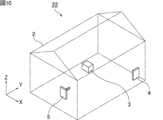
実施例1では、図4に示す送電器10と、図7に示す受電器18と、アルミニウムからなる骨組みと亜鉛メッシュ壁面とアルミニウム床面からなる電磁波遮蔽部材2とから構成される、図8に示す無線電力伝送システム19を考える。In Example 1, a wireless
無線電力伝送システム19は切妻屋根を持った形状をしている。X軸方向の長さaは1500mm、Y軸方向の長さbは1800mmである。垂直に立った壁部分の高さは1500mm、切妻屋根も含めた高さは1960mmである。共振周波数調整部5はYZ面上に設置されており、送電部4の送電器10は共振周波数調整部5と対向するYZ面上に設置されている。また、受電部3の受電器18は床面から1000mmの高さでXY面内の中央位置に設置されている。The wireless
受電器18はプリント基板配線21と整流回路8との間をつなぐ金属ワイヤー20からなる。受電器18はプリント基板配線21を2つ有しており、これらを投影させて重なるように見える方向を、受電アンテナ方向としてここでは定義する。なお、受電器18の整流回路には10kΩの負荷抵抗を接続して評価を行った。The
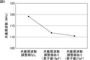
また、共振周波数調整部5に取り付けられている、導電性突起部15は直径1mmΦ、長さ600mmのCuロッドで構成した。伝送線路16は、インピーダンス50Ωのマイクロストリップライン(配線長L=30mm)の構成で作製した。素子17にはトリマーコンデンサを利用し、キャパシタンス値(素子値または素子パラメータともいう)を18pFと27pFに調整したものをそれぞれ利用した。The
無線電力伝送システム19において、受電アンテナ方向がX軸方向となるように受電器18を設置し、負荷抵抗の両端に発生する電圧が最大となるように、送電器10より照射される電磁波の周波数を調整し、共振周波数の測定を行った。In the wireless
図9は、共振周波数調整部5を取り付けなかったときと、共振周波数調整部5を取り付けた上で素子17の素子値を18pFに設定したときと、共振周波数調整部5を取り付けた上で素子17の素子値を27pFに設定したときの共振周波数の測定結果を示している。図9から、共振周波数調整部5を取り付けることによって、共振周波数は低周波数にシフトし、さらに素子17のキャパシタンス値を調整することによって、共振周波数を制御できることが判る。Figure 9 shows the measurement results of the resonance frequency when the resonance
このように、共振周波数調整部5を共振器の壁面に設置した上で、共振周波数調整部5の電気長を調整することによって、自由に共振周波数を制御することができる。これによって、共振器のサイズや内包物に関わらず、一定の周波数で無線電力伝送可能なシステムを提供することが可能となる。In this way, the resonant frequency can be freely controlled by installing the resonant
[実施例2]
図10は本発明の実施例2に係る無線電力伝送システム22の模式図である。[Example 2]
Second Embodiment FIG. 10 is a schematic diagram of a wireless
実施例2では、図4に示す送電器10と、図7に示す受電器18と、アルミニウムからなる骨組みと亜鉛メッシュ壁面とアルミニウム床面からなる電磁波遮蔽部材2とから構成される、図10に示す無線電力伝送システム22を考える。実施例1の無線電力伝送システム19では共振周波数調整部5がYZ面上に設置されたのに対し、実施例2の無線電力伝送システム22では共振周波数調整部5がZX面上に設置されている。In Example 2, a wireless
以上のように用意した無線電力伝送システム22を用いて、実施例1と同様の条件で共振周波数を測定した結果を図11に示す。図11に示すように、共振周波数調整部5をZX面上に設置した場合には、共振周波数調整部5の有無や、素子17のキャパシタンス値に関わらず、共振周波数が一定となることが明らかとなった。The results of measuring the resonant frequency under the same conditions as in Example 1 using the wireless
実施例1および実施例2の結果から、TE基底モード共振を利用する場合には、共振周波数調整部5の設置位置は、共振モードのモード次数がゼロとなる軸と直交する共振器の壁面であることが好ましいことが判る。
[実施例3]
図12Aは本発明の実施例3に係る無線電力伝送システム23における電界強度分布の模式図である。図12Bは共振周波数調整部5を設置する前の無線電力伝送システム23における電界強度分布の模式図である。無線電力伝送システム23に供される共振器は、X軸方向の長さが500mm、Y軸方向の長さが600mm、Z軸方向の長さが400mmの直方体形状をしている。共振周波数調整部5はYZ面上に設置されており、送電部4は共振周波数調整部5と対向するYZ面上に設置されている。 From the results of Examples 1 and 2, it can be seen that when utilizing TE fundamental mode resonance, it is preferable to install the resonance
[Example 3]
Fig. 12A is a schematic diagram of an electric field intensity distribution in a wireless
送電部4と対向するYZ面において、上述した相対電界強度が最大となる位置を0として、共振周波数調整部5をY軸方向に移動させたときの共振周波数を測定した。On the YZ plane facing the
無線電力伝送システム23における、共振周波数調整部5の取付位置に対する、共振周波数の関係を図13に示す。図13では、共振周波数調整部5を取り付けなかったときの共振周波数を破線で示している。図13に示すように、共振周波数調整部5を取り付ける位置に関わらず、共振周波数調整部5を取り付けない場合に比べて共振周波数を低周波数にシフトできることが判る。Figure 13 shows the relationship of the resonant frequency to the mounting position of the resonant
さらに、無線電力伝送システム23における、導電性突起部15の開放端が配置される位置の相対電界強度に対する、共振周波数の変化率を図14に示す。共振周波数の変化率は、共振周波数調整部5を取り付けなかったときの共振周波数を基準として、共振周波数調整部5を取り付けたときの共振周波数を規格化した変化率であり、共振周波数調整部5を取り付けたときの共振周波数が共振周波数調整部5を取り付けなかったときの共振周波数と同じ場合は0となる。図14に示すように、素子17としてインダクタおよびキャパシタのいずれを取り付けた場合においても、相対電界強度が0.2以上である位置に導電性突起部15の開放端を配置すると、共振周波数に変化が生じることが判る。Furthermore, FIG. 14 shows the rate of change of the resonant frequency with respect to the relative electric field strength at the position where the open end of the
[実施例4]
図15は本発明の実施例4に係る無線電力伝送システム24の模式図である。無線電力伝送システム24に供される共振器は、X軸方向の長さが500mm、Y軸方向の長さが600mm、Z軸方向の長さが400mmの直方体形状をしている。共振周波数調整部5はYZ面上に設置されており、送電部4は共振周波数調整部5と対向するYZ面上に設置されている。[Example 4]
15 is a schematic diagram of a wireless
図16は本発明の実施例4に係る共振周波数調整部5の模式図である。導電性突起部15は全長が90mmであり、電磁波遮蔽部材2から内側に向けて80mm突き出している。伝送線路16の長さを変化させたときの共振周波数を測定した。伝送線路16の長さを10mm、40mmまたは70mmに変化させることで、共振周波数調整部5の線路長をそれぞれ110mm、140mmおよび170mmとした。Figure 16 is a schematic diagram of the resonant
無線電力伝送システム24における、共振周波数調整部5の線路長に対する、共振周波数の関係を図17に示す。図17では、共振周波数調整部5を取り付けなかったときの共振周波数を破線で示している。図17に示すように、共振周波数調整部5の線路長に関わらず、共振周波数調整部5を取り付けない場合に比べて共振周波数を低周波数にシフトできることが判る。特に、共振周波数調整部5の線路長が長くなるほど、共振周波数の変化量が大きくなる。Figure 17 shows the relationship of the resonant frequency to the line length of the resonant
また、共振周波数調整部5の線路長を110mmに固定して、伝送線路16に素子17を取り付けたときの共振周波数を測定した。素子17にはキャパシタまたはインダクタを利用した。素子パラメータであるキャパシタンス値(pF)またはインダクタンス値(nH)を変化させた。In addition, the line length of the resonant
無線電力伝送システム24における、素子パラメータに対する、共振周波数の関係を図18に示す。図18では、共振周波数調整部5を取り付けなかったときの共振周波数を破線で示している。図18に示すように、素子17のキャパシタンス値またはインダクタンス値を調整することによって、共振周波数を制御できることが判る。Figure 18 shows the relationship between the resonant frequency and the element parameters in the wireless
1、19、22、23、24 無線電力伝送システム
2 電磁波遮蔽部材
3 受電部
4 送電部
5 共振周波数調整部
6、18 受電器
7 ダイポールアンテナ(電気配線部)
8 整流回路
9 ループアンテナ(電気配線部)
10 送電器
11 整合回路
12 高周波電源
13 金属棒
14 送電アンテナ配線
15 導電性突起部
16 伝送線路
17 素子
20 金属ワイヤー
21 プリント基板配線 1, 19, 22, 23, 24 Wireless
8
REFERENCE SIGNS
Claims (11)
Translated fromJapanese前記共振周波数調整部は、開放端を有する少なくとも1つの導電性突起部と、前記導電性突起部の開放端でない他端に接続されている伝送線路と、を備え、
前記導電性突起部の開放端は、前記構造体の内側に配置され、
前記導電性突起部との接続部ではない前記伝送線路の他端は、前記構造体の壁面をなす前記電磁波遮蔽部材と電気的に接続され、
前記送電部は、送電器と整合回路と電源とを備え、
前記整合回路は、あらかじめ設定された送電周波数において共振器とインピーダンス整合を取るように調整されており、
一定の前記送電周波数を利用する、無線電力伝送システム。 A structure entirely surrounded by an electromagnetic wave shielding member having appropriate electrical conductivity and frequency selectivity, at least one power receiving unit, at least one power transmitting unit, and at least one resonant frequency adjusting unit;
the resonant frequency adjustment unit includes at least one conductive protrusion having an open end, and a transmission line connected to the other end of the conductive protrusion that is not the open end,
the open end of the conductive protrusion is disposed inside the structure;
the other end of the transmission line, which is not the connection portion with the conductive protrusion, is electrically connected to the electromagnetic wave shielding member that forms a wall surface of the structure;
the power transmitting unit includes a power transmitter, a matching circuit, and a power source;
The matching circuit is adjusted to achieve impedance matching with the resonator at a preset power transmission frequency,
A wireless power transmission systemthat utilizes a certain transmission frequency .
前記共振周波数調整部は、前記構造体の内側に配置するための開放端を有する少なくとも1つの導電性突起部と、前記導電性突起部の開放端でない他端に接続されている伝送線路であり、前記導電性突起部との接続部ではない他端を、前記構造体の壁面をなす前記電磁波遮蔽部材と電気的に接続するための伝送線路と、を備え、
前記送電部は、送電器と整合回路と電源とを備え、
前記整合回路は、あらかじめ設定された送電周波数において共振器とインピーダンス整合を取るように調整されており、
前記無線電力伝送システムは、一定の前記送電周波数を利用する、無線電力伝送システム用の共振周波数調整部。 A resonant frequency adjustment unit for a wireless power transmission system, comprising a structure entirely surrounded by an electromagnetic wave shielding member having suitable electrical conductivity and frequency selectivity, at least one power receiving unit, and at least one power transmitting unit,
the resonant frequency adjustment section comprises at least one conductive protrusion having an open end for placement inside the structure, and a transmission line connected to the other end other than the open end of the conductive protrusion, the transmission line being for electrically connecting the other end other than the connection part with the conductive protrusion to the electromagnetic wave shielding member forming a wall surface of the structure;
the power transmitting unit includes a power transmitter, a matching circuit, and a power source;
The matching circuit is adjusted to achieve impedance matching with the resonator at a preset power transmission frequency,
A resonant frequency adjustment unit fora wireless power transmission system, the wireless power transmission system utilizing a constant transmission frequency .
Applications Claiming Priority (3)
| Application Number | Priority Date | Filing Date | Title |
|---|---|---|---|
| JP2021015045 | 2021-02-02 | ||
| JP2021015045 | 2021-02-02 | ||
| PCT/JP2021/042458WO2022168401A1 (en) | 2021-02-02 | 2021-11-18 | Wireless power transmission system and resonance frequency adjustment unit for wireless power transmission system |
Publications (3)
| Publication Number | Publication Date |
|---|---|
| JPWO2022168401A1 JPWO2022168401A1 (en) | 2022-08-11 |
| JPWO2022168401A5 JPWO2022168401A5 (en) | 2023-09-27 |
| JP7540654B2true JP7540654B2 (en) | 2024-08-27 |
Family
ID=82741086
Family Applications (1)
| Application Number | Title | Priority Date | Filing Date |
|---|---|---|---|
| JP2022579347AActiveJP7540654B2 (en) | 2021-02-02 | 2021-11-18 | WIRELESS POWER TRANSMISSION SYSTEM AND RESONANT FREQUENCY ADJUSTMENT UNIT FOR WIRELESS POWER TRANSMISSION SYSTEM |
Country Status (4)
| Country | Link |
|---|---|
| US (1) | US12218517B2 (en) |
| JP (1) | JP7540654B2 (en) |
| CN (1) | CN116888855A (en) |
| WO (1) | WO2022168401A1 (en) |
Families Citing this family (1)
| Publication number | Priority date | Publication date | Assignee | Title |
|---|---|---|---|---|
| WO2024144424A1 (en)* | 2022-12-26 | 2024-07-04 | Федеральное государственное автономное образовательное учреждение высшего образования "Национальный исследовательский университет ИТМО" | Device for wireless power transmission |
Citations (5)
| Publication number | Priority date | Publication date | Assignee | Title |
|---|---|---|---|---|
| US20160164301A1 (en) | 2014-12-08 | 2016-06-09 | Disney Enterprises, Inc. | Resonant cavity mode enabled wireless power transfer |
| JP2017188985A (en) | 2016-04-01 | 2017-10-12 | 国立大学法人豊橋技術科学大学 | Wireless power transmission system |
| US20180097402A1 (en) | 2016-10-03 | 2018-04-05 | Disney Enterprises, Inc. | Wireless power transmission |
| JP2019041529A (en) | 2017-08-28 | 2019-03-14 | 国立大学法人豊橋技術科学大学 | Radio power transmission system |
| JP2020089209A (en) | 2018-11-30 | 2020-06-04 | 国立大学法人豊橋技術科学大学 | Power transmitter and receiver, and wireless power transmission system using the same |
- 2021
- 2021-11-18JPJP2022579347Apatent/JP7540654B2/enactiveActive
- 2021-11-18WOPCT/JP2021/042458patent/WO2022168401A1/ennot_activeCeased
- 2021-11-18CNCN202180092342.9Apatent/CN116888855A/enactivePending
- 2023
- 2023-08-01USUS18/363,412patent/US12218517B2/enactiveActive
Patent Citations (5)
| Publication number | Priority date | Publication date | Assignee | Title |
|---|---|---|---|---|
| US20160164301A1 (en) | 2014-12-08 | 2016-06-09 | Disney Enterprises, Inc. | Resonant cavity mode enabled wireless power transfer |
| JP2017188985A (en) | 2016-04-01 | 2017-10-12 | 国立大学法人豊橋技術科学大学 | Wireless power transmission system |
| US20180097402A1 (en) | 2016-10-03 | 2018-04-05 | Disney Enterprises, Inc. | Wireless power transmission |
| JP2019041529A (en) | 2017-08-28 | 2019-03-14 | 国立大学法人豊橋技術科学大学 | Radio power transmission system |
| JP2020089209A (en) | 2018-11-30 | 2020-06-04 | 国立大学法人豊橋技術科学大学 | Power transmitter and receiver, and wireless power transmission system using the same |
Also Published As
| Publication number | Publication date |
|---|---|
| US20230378814A1 (en) | 2023-11-23 |
| WO2022168401A1 (en) | 2022-08-11 |
| US12218517B2 (en) | 2025-02-04 |
| CN116888855A (en) | 2023-10-13 |
| JPWO2022168401A1 (en) | 2022-08-11 |
Similar Documents
| Publication | Publication Date | Title |
|---|---|---|
| US7215289B2 (en) | Antenna device and portable radio terminal | |
| US8542153B2 (en) | Slot halo antenna device | |
| CN106716715B (en) | Antenna device and wireless device | |
| US20150288074A1 (en) | Sar reduction in radio transmitting devices | |
| US20020101382A1 (en) | Chip antenna and antenna unit including the same | |
| CN212676478U (en) | Antenna device and communication terminal device | |
| JP6258045B2 (en) | antenna | |
| TW201533973A (en) | Portable wireless apparatus | |
| US12412979B2 (en) | Antenna device and communication terminal apparatus | |
| RU154886U1 (en) | SMALL VIBRATOR ANTENNA OF SYSTEMS OF DATA TRANSMISSION NETWORK IN THE RANGE OF MEDIUM AND INTERMEDIATE WAVES | |
| KR101891084B1 (en) | Aperture-coupled microstrip antenna and manufacturing method thereof | |
| JP6973781B2 (en) | Wireless power transmission system | |
| JP7540654B2 (en) | WIRELESS POWER TRANSMISSION SYSTEM AND RESONANT FREQUENCY ADJUSTMENT UNIT FOR WIRELESS POWER TRANSMISSION SYSTEM | |
| US20150009093A1 (en) | Antenna apparatus and portable wireless device equipped with the same | |
| US20240413665A1 (en) | Wireless power transfer system | |
| US20120056788A1 (en) | Multiband and broadband antenna using metamaterials, and communication apparatus comprising the same | |
| TWI641185B (en) | Communication device and antenna assembly thereof | |
| KR20120101956A (en) | Multi-band antenna | |
| JP7548444B2 (en) | Wireless power transmission system and receiver | |
| KR20140143969A (en) | Antenna apparatus and feeding structure thereof | |
| KR100406284B1 (en) | Mini-Antenna for International Mobile Telecommunication-2000 Terminal Equipment for Bulk Type Dielectric | |
| KR20100092996A (en) | E-loop antenna radiating electrical far-field with omni-directional | |
| KR101128410B1 (en) | Microstrip Antenna To Tune Resonant Frequency with Voltage Control | |
| JP2016152531A (en) | Wireless communication device and electronic apparatus | |
| JP2016152532A (en) | Radio communication device and electronic apparatus |
Legal Events
| Date | Code | Title | Description |
|---|---|---|---|
| A521 | Request for written amendment filed | Free format text:JAPANESE INTERMEDIATE CODE: A523 Effective date:20230705 | |
| A621 | Written request for application examination | Free format text:JAPANESE INTERMEDIATE CODE: A621 Effective date:20230705 | |
| A521 | Request for written amendment filed | Free format text:JAPANESE INTERMEDIATE CODE: A523 Effective date:20230724 | |
| TRDD | Decision of grant or rejection written | ||
| A01 | Written decision to grant a patent or to grant a registration (utility model) | Free format text:JAPANESE INTERMEDIATE CODE: A01 Effective date:20240730 | |
| A61 | First payment of annual fees (during grant procedure) | Free format text:JAPANESE INTERMEDIATE CODE: A61 Effective date:20240805 | |
| R150 | Certificate of patent or registration of utility model | Ref document number:7540654 Country of ref document:JP Free format text:JAPANESE INTERMEDIATE CODE: R150 |