JP7539883B2 - Biopsy device with manual firing mechanism - Google Patents
Biopsy device with manual firing mechanismDownload PDFInfo
- Publication number
- JP7539883B2 JP7539883B2JP2021527212AJP2021527212AJP7539883B2JP 7539883 B2JP7539883 B2JP 7539883B2JP 2021527212 AJP2021527212 AJP 2021527212AJP 2021527212 AJP2021527212 AJP 2021527212AJP 7539883 B2JP7539883 B2JP 7539883B2
- Authority
- JP
- Japan
- Prior art keywords
- cutter
- catch
- biopsy device
- needle
- manifold
- Prior art date
- Legal status (The legal status is an assumption and is not a legal conclusion. Google has not performed a legal analysis and makes no representation as to the accuracy of the status listed.)
- Active
Links
- 238000001574biopsyMethods0.000titleclaimsdescription126
- 238000010304firingMethods0.000titleclaimsdescription65
- 230000007246mechanismEffects0.000titleclaimsdescription24
- 239000000523sampleSubstances0.000claimsdescription80
- 238000004891communicationMethods0.000claimsdescription8
- 230000004044responseEffects0.000claimsdescription7
- 230000007704transitionEffects0.000claimsdescription6
- 238000002604ultrasonographyMethods0.000claimsdescription6
- 210000001519tissueAnatomy0.000description60
- 238000000034methodMethods0.000description25
- 239000000463materialSubstances0.000description17
- 230000003902lesionEffects0.000description14
- 230000003068static effectEffects0.000description8
- 239000012530fluidSubstances0.000description7
- 230000013011matingEffects0.000description7
- 230000005855radiationEffects0.000description4
- 230000005540biological transmissionEffects0.000description3
- 238000004140cleaningMethods0.000description3
- 238000003780insertionMethods0.000description3
- 230000037431insertionEffects0.000description3
- 238000012986modificationMethods0.000description3
- 230000004048modificationEffects0.000description3
- 238000013519translationMethods0.000description3
- 230000008878couplingEffects0.000description2
- 238000010168coupling processMethods0.000description2
- 238000005859coupling reactionMethods0.000description2
- 238000000605extractionMethods0.000description2
- 230000035515penetrationEffects0.000description2
- 238000001356surgical procedureMethods0.000description2
- 238000013022ventingMethods0.000description2
- VZSRBBMJRBPUNF-UHFFFAOYSA-N2-(2,3-dihydro-1H-inden-2-ylamino)-N-[3-oxo-3-(2,4,6,7-tetrahydrotriazolo[4,5-c]pyridin-5-yl)propyl]pyrimidine-5-carboxamideChemical compoundC1C(CC2=CC=CC=C12)NC1=NC=C(C=N1)C(=O)NCCC(N1CC2=C(CC1)NN=N2)=OVZSRBBMJRBPUNF-UHFFFAOYSA-N0.000description1
- DXCXWVLIDGPHEA-UHFFFAOYSA-N2-[4-[2-(2,3-dihydro-1H-inden-2-ylamino)pyrimidin-5-yl]-3-[(4-ethylpiperazin-1-yl)methyl]pyrazol-1-yl]-1-(2,4,6,7-tetrahydrotriazolo[4,5-c]pyridin-5-yl)ethanoneChemical compoundC1C(CC2=CC=CC=C12)NC1=NC=C(C=N1)C=1C(=NN(C=1)CC(=O)N1CC2=C(CC1)NN=N2)CN1CCN(CC1)CCDXCXWVLIDGPHEA-UHFFFAOYSA-N0.000description1
- FYELSNVLZVIGTI-UHFFFAOYSA-N2-[4-[2-(2,3-dihydro-1H-inden-2-ylamino)pyrimidin-5-yl]-5-ethylpyrazol-1-yl]-1-(2,4,6,7-tetrahydrotriazolo[4,5-c]pyridin-5-yl)ethanoneChemical compoundC1C(CC2=CC=CC=C12)NC1=NC=C(C=N1)C=1C=NN(C=1CC)CC(=O)N1CC2=C(CC1)NN=N2FYELSNVLZVIGTI-UHFFFAOYSA-N0.000description1
- APLNAFMUEHKRLM-UHFFFAOYSA-N2-[5-[2-(2,3-dihydro-1H-inden-2-ylamino)pyrimidin-5-yl]-1,3,4-oxadiazol-2-yl]-1-(3,4,6,7-tetrahydroimidazo[4,5-c]pyridin-5-yl)ethanoneChemical compoundC1C(CC2=CC=CC=C12)NC1=NC=C(C=N1)C1=NN=C(O1)CC(=O)N1CC2=C(CC1)N=CN2APLNAFMUEHKRLM-UHFFFAOYSA-N0.000description1
- YLZOPXRUQYQQID-UHFFFAOYSA-N3-(2,4,6,7-tetrahydrotriazolo[4,5-c]pyridin-5-yl)-1-[4-[2-[[3-(trifluoromethoxy)phenyl]methylamino]pyrimidin-5-yl]piperazin-1-yl]propan-1-oneChemical compoundN1N=NC=2CN(CCC=21)CCC(=O)N1CCN(CC1)C=1C=NC(=NC=1)NCC1=CC(=CC=C1)OC(F)(F)FYLZOPXRUQYQQID-UHFFFAOYSA-N0.000description1
- 241000894006BacteriaSpecies0.000description1
- IAYPIBMASNFSPL-UHFFFAOYSA-NEthylene oxideChemical compoundC1CO1IAYPIBMASNFSPL-UHFFFAOYSA-N0.000description1
- FAPWRFPIFSIZLT-UHFFFAOYSA-MSodium chlorideChemical compound[Na+].[Cl-]FAPWRFPIFSIZLT-UHFFFAOYSA-M0.000description1
- 239000004775TyvekSubstances0.000description1
- 229920000690TyvekPolymers0.000description1
- 230000006978adaptationEffects0.000description1
- 239000000853adhesiveSubstances0.000description1
- 230000001070adhesive effectEffects0.000description1
- 230000008859changeEffects0.000description1
- 238000010276constructionMethods0.000description1
- 238000010586diagramMethods0.000description1
- 230000007170pathologyEffects0.000description1
- 238000003825pressingMethods0.000description1
- 230000008569processEffects0.000description1
- 238000007789sealingMethods0.000description1
- 239000011780sodium chlorideSubstances0.000description1
- 210000004872soft tissueAnatomy0.000description1
- 239000007787solidSubstances0.000description1
- 230000001954sterilising effectEffects0.000description1
- 238000004659sterilization and disinfectionMethods0.000description1
- 238000012546transferMethods0.000description1
Images


Classifications
- A—HUMAN NECESSITIES
- A61—MEDICAL OR VETERINARY SCIENCE; HYGIENE
- A61B—DIAGNOSIS; SURGERY; IDENTIFICATION
- A61B10/00—Instruments for taking body samples for diagnostic purposes; Other methods or instruments for diagnosis, e.g. for vaccination diagnosis, sex determination or ovulation-period determination; Throat striking implements
- A61B10/02—Instruments for taking cell samples or for biopsy
- A61B10/0233—Pointed or sharp biopsy instruments
- A61B10/0266—Pointed or sharp biopsy instruments means for severing sample
- A61B10/0275—Pointed or sharp biopsy instruments means for severing sample with sample notch, e.g. on the side of inner stylet
- A—HUMAN NECESSITIES
- A61—MEDICAL OR VETERINARY SCIENCE; HYGIENE
- A61B—DIAGNOSIS; SURGERY; IDENTIFICATION
- A61B10/00—Instruments for taking body samples for diagnostic purposes; Other methods or instruments for diagnosis, e.g. for vaccination diagnosis, sex determination or ovulation-period determination; Throat striking implements
- A61B10/02—Instruments for taking cell samples or for biopsy
- A61B10/0233—Pointed or sharp biopsy instruments
- A61B10/0283—Pointed or sharp biopsy instruments with vacuum aspiration, e.g. caused by retractable plunger or by connected syringe
- A—HUMAN NECESSITIES
- A61—MEDICAL OR VETERINARY SCIENCE; HYGIENE
- A61B—DIAGNOSIS; SURGERY; IDENTIFICATION
- A61B10/00—Instruments for taking body samples for diagnostic purposes; Other methods or instruments for diagnosis, e.g. for vaccination diagnosis, sex determination or ovulation-period determination; Throat striking implements
- A61B10/02—Instruments for taking cell samples or for biopsy
- A61B2010/0208—Biopsy devices with actuators, e.g. with triggered spring mechanisms
Landscapes
- Health & Medical Sciences (AREA)
- Life Sciences & Earth Sciences (AREA)
- Medical Informatics (AREA)
- Engineering & Computer Science (AREA)
- Biomedical Technology (AREA)
- Heart & Thoracic Surgery (AREA)
- Pathology (AREA)
- Molecular Biology (AREA)
- Surgery (AREA)
- Animal Behavior & Ethology (AREA)
- General Health & Medical Sciences (AREA)
- Public Health (AREA)
- Veterinary Medicine (AREA)
- Surgical Instruments (AREA)
Description
Translated fromJapanese 優先権
本出願は、その開示が参照により本明細書に組み込まれる2018年11月20日に出願された「Biopsy Device with Manual Firing Mechanism」と題する、米国仮特許出願第62/769,956号に対する優先権を主張する。 PRIORITY This application claims priority to U.S. Provisional Patent Application No. 62/769,956, entitled "Biopsy Device with Manual Firing Mechanism," filed November 20, 2018, the disclosure of which is incorporated herein by reference.
生検試料は、様々な装置を使用する種々の医療処置にて、多様な方法で得られてきた。生検装置は、定位誘導、超音波誘導、MRI誘導、PEM誘導、BSGI誘導または他の方法の下で使用され得る。例えば、いくつかの生検装置は、患者から1つ以上の生検試料を取得するために、片手を使って及び1回の挿入で、ユーザによって完全に操作可能であり得る。さらに、いくつかの生検装置は、流体(例えば、加圧空気、生理食塩水、大気空気、真空など)の伝達、動力の伝達及び/または命令の伝達などのための真空モジュール及び/または制御モジュールに接続され得る。他の生検装置は、別の装置に接続されることなく、または他の方法で連結されることなく、完全にまたは少なくとも部分的に操作可能であり得る。他の生検装置は、別の装置に接続されることなく、または他の方法で連結されることなく、完全にまたは少なくとも部分的に操作可能であり得る。Biopsy samples have been obtained in a variety of ways in various medical procedures using a variety of devices. Biopsy devices may be used under stereotactic guidance, ultrasound guidance, MRI guidance, PEM guidance, BSGI guidance or other methods. For example, some biopsy devices may be fully operable by a user using one hand and with one insertion to obtain one or more biopsy samples from a patient. Additionally, some biopsy devices may be connected to a vacuum module and/or a control module for the transmission of fluids (e.g., pressurized air, saline, atmospheric air, vacuum, etc.), the transmission of power, and/or the transmission of commands, etc. Other biopsy devices may be fully or at least partially operable without being connected or otherwise coupled to another device. Other biopsy devices may be fully or at least partially operable without being connected or otherwise coupled to another device.
単に例示的な生検装置は、1996年6月18日に発行された「Method and Apparatus for Automated Biopsy and Collection of Soft Tissue」と題する米国特許第5,526,822号、2000年7月11日に発行された「Control Apparatus for an Automated Surgical Biopsy Device」と題する米国特許第6,086,544号、2003年9月30日に発行された「MRI Compatible Surgical Biopsy Device」と題する米国特許第6,626,849号、2008年10月28日に発行された「Remote Thumbwheel for a Surgical Biopsy Device」と題する米国特許第7,442,171号、2014年7月7日に発行された「Handheld Biopsy Device with Needle Firing」と題する米国特許第8,764,680号、2016年5月24日に発行された「Presentation of Biopsy Sample by Biopsy Device」と題する米国特許第9,345,457号、2006年4月6日に公開され、現在は放棄された「Biopsy Apparatus and Method」と題する米国公開第2006/0074345号、2009年7月2日に公開され、「Clutch and Valving System for Tetherless Biopsy Device」と題する米国公開第2009/0171242号、2010年6月17日に公開され、「Hand Actuated Tetherless Biopsy Device with Pistol Grip」と題する米国公開第2010/0152610号、及び2012年12月6日に公開され、「Needle Assembly and Blade Assembly for Biopsy Device」と題する米国公開第2012/0310110号に開示されている。上記に引用した米国特許番号、米国特許出願公開、及び米国非仮特許出願の各々の開示は、参照により本明細書に組み込まれる。Merely exemplary biopsy devices include U.S. Patent No. 5,526,822, issued June 18, 1996, entitled "Method and Apparatus for Automated Biopsy and Collection of Soft Tissue," U.S. Patent No. 6,086,544, issued July 11, 2000, entitled "Control Apparatus for an Automated Surgical Biopsy Device," U.S. Patent No. 6,086,544, issued September 30, 2003, entitled "MRI Compatible ... No. 6,626,849 entitled "Remote Thumbwheel for a Surgical Biopsy Device" issued on October 28, 2008, U.S. Patent No. 7,442,171 entitled "Remote Thumbwheel for a Surgical Biopsy Device" issued on July 7, 2014, U.S. Patent No. 8,764,680 entitled "Handheld Biopsy Device with Needle Firing" issued on May 24, 2016, U.S. Patent No. 8,764,680 entitled "Presentation of Biopsy Sample by Biopsy Device ... No. 9,345,457, published on April 6, 2006, and now abandoned, entitled "Biopsy Apparatus and Method," U.S. Publication No. 2006/0074345, published on July 2, 2009, and now abandoned, entitled "Clutch and Valving System for Tetherless Biopsy Device," U.S. Publication No. 2009/0171242, published on June 17, 2010, and now abandoned, entitled "Hand Actuated Tetherless Biopsy Device with Pistol," and U.S. Publication No. 2012/0310110, published December 6, 2012, entitled "Needle Assembly and Blade Assembly for Biopsy Device." The disclosures of each of the above-cited U.S. patent numbers, U.S. patent application publications, and U.S. non-provisional patent applications are incorporated herein by reference.
状況によっては、手動作動式針発射機構を生検装置の中に組み込んで、生検装置の針を病変に直接的に発射することが望ましい場合がある。例えば、いくつかの従来の非発射生検装置では、針は患者の中に手作業で挿入され、次に病変自体及び/または隣接する組織から組織試料を採取するために病変の下方にまたは病変に隣接して配置される。そのような装置では、依然として手作業での挿入を使用することが望ましい場合もあるが、針を病変に隣接して配置するよりもむしろ、針を病変に直接的に発射することが望ましい場合もある。In some situations, it may be desirable to incorporate a manually actuated needle firing mechanism into the biopsy device to fire the needle of the biopsy device directly into the lesion. For example, in some conventional non-firing biopsy devices, the needle is manually inserted into the patient and then positioned below or adjacent to the lesion to obtain a tissue sample from the lesion itself and/or adjacent tissue. In such devices, it may still be desirable to use manual insertion, but it may be desirable to fire the needle directly into the lesion rather than positioning the needle adjacent to the lesion.
生検試料を得るためにいくつかのシステム及び方法が作成され、使用されてきたが、本発明者に先行して添付の「特許請求の範囲」に説明した発明を作成または使用した者はいなかったと考えられる。Although several systems and methods have been made and used to obtain biopsy samples, it is believed that no one prior to the present inventors has made or used the invention described in the accompanying claims.
本明細書は、生検装置を具体的に指摘し、明確に主張する「特許請求の範囲」で完結するが、本生検装置は、添付の図面と併せて考慮される以下の特定の実施例の説明からより良好に理解されると考えられ、図面で類似の参照符号は同じ要素を指す。This specification concludes with claims particularly pointing out and distinctly claiming a biopsy device, which is believed to be better understood from the following description of specific embodiments considered in conjunction with the accompanying drawings, in which like reference numerals refer to the same elements.
生検装置の特定の実施例に関する以下の説明は、本生検装置の範囲を限定するために使用されるべきではない。生検装置の他の実施例、特徴、態様、実施形態、及び利点は、例示として生検装置を実施するために企図される最良の形態のうちの1つである以下の説明から当業者に明らかになる。理解されるように、生検装置は、すべて生検装置の趣旨から逸脱することなく、他の様々かつ明白な態様を可能にする。したがって図面及び説明は本質的に例示であり、限定的ではないとみなされるべきである。The following description of a particular example of a biopsy device should not be used to limit the scope of the biopsy device. Other examples, features, aspects, embodiments, and advantages of the biopsy device will become apparent to those skilled in the art from the following description, which is one of the best modes contemplated for carrying out the biopsy device by way of example. As will be appreciated, the biopsy device allows for other various and obvious aspects, all without departing from the spirit of the biopsy device. Thus, the drawings and description should be considered as illustrative in nature and not limiting.
参照により本明細書に組み込まれると言われている任意の特許、刊行物または他の開示資料は、全部または一部において、組み込まれる資料が本開示に記載の既存の定義、記述または他の開示資料と矛盾しない範囲でのみ、本明細書に組み込まれることを理解されたい。したがって、また必要な範囲で、本明細書に明確に記載された開示は、参照により本明細書に組み込まれた任意の相反する資料に優先する。参照により本明細書に組み込まれると言われているが、本明細書に記載されている既存の定義、記述もしくは他の開示資料と矛盾する任意の資料またはその一部は、その組み込まれた資料と既存の開示資料との間に矛盾が生じない範囲でのみ組み込まれる。Any patent, publication, or other disclosure material that is said to be incorporated by reference herein is understood to be incorporated herein, in whole or in part, only to the extent that the incorporated material does not conflict with existing definitions, descriptions or other disclosure material set forth in this disclosure. Thus, and to the extent necessary, the disclosure as expressly set forth herein takes precedence over any conflicting material incorporated herein by reference. Any material, or portion thereof, that is said to be incorporated by reference herein but that conflicts with existing definitions, descriptions or other disclosure material set forth herein is incorporated only to the extent that no conflict arises between the incorporated material and the existing disclosure material.
I.例示的な生検装置の概要
図1は、プローブ(20)及びホルスター(30)を含む例示的な生検装置(10)を示す。プローブ(20)は、少なくとも部分的にプローブ(20)のケーシングから遠位に延びる針アセンブリ(100)を含む。針アセンブリ(100)は、以下に説明するように組織試料を得るために患者の組織に挿入できる。生検装置(10)は、組織試料が中に付着される組織試料ホルダー(40)をさらに含む。ほんの一例として、プローブ(20)は、使い捨て可能な構成要素であり得、ホルスター(30)は、図2に示すように、プローブ(20)を結合し得る再利用可能な構成要素であり得る。本明細書での用語「ホルスター」の使用は、プローブ(20)の任意の部分をホルスター(30)の任意の部分に挿入することを必要とすると解釈されるべきではない。実際に、生検装置(10)の1つの構成では、プローブ(20)は、単にホルスター(30)の上に配置されるにすぎない場合がある。代わりに、プローブ(20)の一部分は、プローブ(20)をホルスター(30)に固定するためにホルスター(30)に挿入し得る。さらに別の構成では、ホルスター(30)の一部分は、プローブ(20)に挿入し得る。なおさらに、プローブ(20)及びホルスター(30)は、単一のユニットとして一体で形成し得る。 I. Overview of an Exemplary Biopsy Device FIG. 1 illustrates an exemplary biopsy device (10) including a probe (20) and a holster (30). The probe (20) includes a needle assembly (100) that extends distally from a casing of the probe (20) at least partially. The needle assembly (100) can be inserted into a patient's tissue to obtain a tissue sample, as described below. The biopsy device (10) further includes a tissue sample holder (40) in which a tissue sample is attached. By way of example only, the probe (20) can be a disposable component and the holster (30) can be a reusable component to which the probe (20) can be coupled, as shown in FIG. 2. Use of the term "holster" herein should not be construed as requiring that any portion of the probe (20) be inserted into any portion of the holster (30). Indeed, in one configuration of the biopsy device (10), the probe (20) may simply be disposed on the holster (30). Alternatively, a portion of probe (20) may be inserted into holster (30) to secure probe (20) to holster (30). In yet another configuration, a portion of holster (30) may be inserted into probe (20). Still further, probe (20) and holster (30) may be integrally formed as a single unit.
プローブ(20)及びホルスター(30)が分離可能な部材である構成では、ホルスター(30)内の真空ポンプ(50)によって生成された真空がプローブ(20)に流体的に連結され得るように、プローブ(20)上の第2のポート及び/またはシール(26)と結合するために、ポート及び/またはシール(32)をホルスター(30)の上に設け得る。また、ホルスター(30)は、プローブ(20)上のギア(310、312)と噛合し、それらと係合するギア(34、36)も提供し得る。ホルスター(30)とプローブ(20)との間で真空及び駆動力を伝達する図2に示す構成は、単に例示的にすぎないことを理解されたい。いくつかのバージョンでは、そのような構成は、その開示が参照により本明細書に組み込まれる、2012年6月26日に発行され、「Tetherless Biopsy Device with Reusable Portion」と題する米国特許第8,206,316号、及び/または2012年3月15日に公開され、「Biopsy Device Tissue Sample Holder with Removable Tray」と題する米国公開第2012/0065542号の教示の少なくともいくつかに従って構築され得る。In configurations where the probe (20) and holster (30) are separable members, a port and/or seal (32) may be provided on the holster (30) to mate with a second port and/or seal (26) on the probe (20) so that a vacuum generated by a vacuum pump (50) in the holster (30) may be fluidly coupled to the probe (20). The holster (30) may also provide gears (34, 36) that mesh with and engage with gears (310, 312) on the probe (20). It should be understood that the configuration shown in FIG. 2 for transmitting vacuum and drive between the holster (30) and the probe (20) is merely exemplary. In some versions, such configurations may be constructed according to at least some of the teachings of U.S. Patent No. 8,206,316, issued June 26, 2012 and entitled "Tetherless Biopsy Device with Reusable Portion," and/or U.S. Publication No. 2012/0065542, issued March 15, 2012 and entitled "Biopsy Device Tissue Sample Holder with Removable Tray," the disclosures of which are incorporated herein by reference.
ホルスター(30)及びプローブ(20)が連結された状態で、真空ポンプ(50)は、組織試料ホルダー(40)及び管状カッター(60)を介して針アセンブリ(100)内で真空を生じさせることができる。しかしながら、真空は他の方法で提供され得ることを理解されたい。例えば、真空ポンプ(50)は、ホルスター(30)及びプローブ(20)から独立している場合があり、生検装置(10)上の適切なポートに真空管によって単に結合される場合がある。生検装置(10)は、その開示が参照により本明細書に組み込まれる、2014年7月1日に発行され、「Handheld Biopsy Device with Needle Firing」と題する米国特許第8,764,680号、及び/または2012年3月15日に公開され、「Biopsy Device Tissue Sample Holder with Removable Tray」と題する米国公開第2012/0065542号の教示の少なくともいくつかに従って構成され得る。プローブ(20)及びホルスター(30)の他の適切な構造上及び機能上の組み合わせは、本明細書の教示を考慮して当業者に明らかになる。With the holster (30) and probe (20) coupled, the vacuum pump (50) can create a vacuum within the needle assembly (100) through the tissue sample holder (40) and the tubular cutter (60). However, it should be understood that the vacuum can be provided in other ways. For example, the vacuum pump (50) can be separate from the holster (30) and probe (20) and can simply be coupled by a vacuum tube to an appropriate port on the biopsy device (10). The biopsy device (10) may be configured according to at least some of the teachings of U.S. Patent No. 8,764,680, issued July 1, 2014 and entitled "Handheld Biopsy Device with Needle Firing," and/or U.S. Publication No. 2012/0065542, issued March 15, 2012 and entitled "Biopsy Device Tissue Sample Holder with Removable Tray," the disclosures of which are incorporated herein by reference. Other suitable structural and functional combinations of probe (20) and holster (30) will be apparent to those skilled in the art in view of the teachings herein.
II.例示的なホルスター
図3に概略で示すホルスター(30)は、真空ポンプ(50)、モータ(70)、制御モジュール(1000)、複数のボタン(54)、真空センサ(52)、及び任意の他の適切な電気的な及び/または電気機械的な構成要素を含む。本例の真空ポンプ(50)は、モータ(70)に機械的に結合された従来の隔膜ポンプを含む。真空センサ(52)は、真空センサ(52)が、真空ポンプ(50)によって生じる真空のレベルを決定できるように、真空ポンプ(50)に結合される、または真空ポンプからの任意の真空経路に沿って結合される。真空センサ(52)は、真空センサ(52)が真空レベルを示す信号を制御モジュール(1000)に出力し得るように、制御モジュール(1000)に電気的に結合されている。示されている構成では、モータ(70)は、以下に説明するように、ボタン(54)の1つ以上の作動に応えてカッター(60)を平行移動及び/または回転させるために、及び真空ポンプ(50)を起動するために操作可能である。ただし、これは任意選択にすぎず、真空ポンプ(50)を運転するために第2のモータ(図示せず)が設けられてもよい。特に、モータは、カッター駆動アセンブリ(図示せず)に結合され得、ボタン(54)の1つ以上を作動させると、制御モジュール(1000)によって起動され得る。そのようなカッター駆動アセンブリ(図示せず)は、ギア(34、36)を同時に回転させ得る。上記のように、ギア(34、36)は、プローブ(20)内でギア(310、312)と噛合し、このようにしてモータ(70)がカッター(60)を平行移動及び/または回転させることを可能にする。ホルスター(30)の他の種々の構成は、本明細書の教示を考慮して当業者に明らかになるように提供され得る。ほんの一例として、カッター駆動アセンブリ(図示せず)及び/またはホルスター(30)の他の特徴は、その開示が参照により本明細書に組み込まれる、2012年6月26日に発行され、「Tetherless Biopsy Device with Reusable Portion」と題する米国特許第8,206,316号及び/または2014年7月1日に発行され、「Handheld Biopsy Device with Needle Firing」と題する米国特許第8,764,680号の教示の少なくともいくつかに従って構築され得る。 II. Exemplary Holster The holster (30), shown generally in FIG. 3, includes a vacuum pump (50), a motor (70), a control module (1000), a plurality of buttons (54), a vacuum sensor (52), and any other suitable electrical and/or electromechanical components. The vacuum pump (50) in this example includes a conventional diaphragm pump mechanically coupled to the motor (70). The vacuum sensor (52) is coupled to the vacuum pump (50) or along any vacuum path from the vacuum pump such that the vacuum sensor (52) can determine the level of vacuum produced by the vacuum pump (50). The vacuum sensor (52) is electrically coupled to the control module (1000) such that the vacuum sensor (52) can output a signal to the control module (1000) indicative of the vacuum level. In the configuration shown, the motor (70) is operable to translate and/or rotate the cutter (60) in response to one or more actuations of the buttons (54) and to activate the vacuum pump (50), as described below. However, this is merely optional, and a second motor (not shown) may be provided to operate the vacuum pump (50). In particular, the motor may be coupled to a cutter drive assembly (not shown) and activated by the control module (1000) upon actuation of one or more of the buttons (54). Such a cutter drive assembly (not shown) may simultaneously rotate the gears (34, 36). As noted above, the gears (34, 36) mesh with the gears (310, 312) within the probe (20), thus enabling the motor (70) to translate and/or rotate the cutter (60). Various other configurations of the holster (30) may be provided as will become apparent to those skilled in the art in view of the teachings herein. By way of example only, the cutter drive assembly (not shown) and/or other features of holster (30) may be constructed in accordance with at least some of the teachings of U.S. Pat. No. 8,206,316, issued June 26, 2012 and entitled "Tetherless Biopsy Device with Reusable Portion," and/or U.S. Pat. No. 8,764,680, issued July 1, 2014 and entitled "Handheld Biopsy Device with Needle Firing," the disclosures of which are incorporated herein by reference.
III.例示的なプローブ
図4は、針アセンブリ(100)、カッター作動アセンブリ(300)、プローブハウジング(22、24)、及び組織試料ホルダー(40)を示す、プローブ(20)の部分的な分解図を示す。針アセンブリ(100)は、針部分(110)及びバルブアセンブリ(200)を含む。以下により詳細に説明するように、針アセンブリ(100)は、一般に、組織を貫通するように操作可能であり、患者から組織試料を切断し、組織試料を組織試料ホルダー(40)に運ぶためにカッター(60)を配置できる。より具体的には、針アセンブリ(100)の針部分(110)は、患者の組織に挿入される。カッター作動アセンブリ(300)は、次にボタン(54)の1つ以上を押した後に、カッター(60)を開放位置に選択的に作動させるように操作可能である。カッター(60)がカッター作動アセンブリ(300)によって開放位置に作動されると、組織は、カッター(60)を通して伝達された真空によって針部分(110)に脱出し得る。カッター(60)は、次にカッター作動アセンブリ(300)によって閉鎖位置に選択的に作動され、脱出した組織を患者から切断し得る。ベントアセンブリ(300)は、次に針部分(110)の一部分を大気に選択的に通気し、このようにして脱出した組織の近端部と末端部との間に圧力差を生じさせるように操作可能である。次に、圧力差によって、脱出した組織はカッター(60)を通して組織試料ホルダー(40)に運ばれる。 III. Exemplary Probes FIG. 4 illustrates a partially exploded view of probe (20), showing needle assembly (100), cutter actuation assembly (300), probe housing (22, 24), and tissue sample holder (40). Needle assembly (100) includes needle portion (110) and valve assembly (200). As described in more detail below, needle assembly (100) is generally operable to penetrate tissue and position cutter (60) to sever a tissue sample from a patient and deliver the tissue sample to tissue sample holder (40). More specifically, needle portion (110) of needle assembly (100) is inserted into tissue of the patient. Cutter actuation assembly (300) is then operable to selectively actuate cutter (60) to an open position after depression of one or more of buttons (54). When cutter (60) is actuated to an open position by cutter actuation assembly (300), tissue may escape into needle portion (110) by vacuum transmitted through cutter (60). Cutter (60) may then be selectively actuated to a closed position by cutter actuation assembly (300) to sever the escaped tissue from the patient. Vent assembly (300) is then operable to selectively vent a portion of needle portion (110) to atmosphere, thus creating a pressure differential between the proximal and distal ends of the escaped tissue. The pressure differential then carries the escaped tissue through cutter (60) to tissue sample holder (40).
A.例示的なカッター作動アセンブリ
カッター作動アセンブリ(300)は、一連のギア(310、312)を含む。ギア(310、312)は、カッター(60)を平行移動及び/または回転させるように構成される。示されている構成では、ギア(310、312)は、プローブ(20)がホルスター(30)に取り付けられているときにモータ(70)に結合される。特に、2つのギア(310、312)は、一方のギア(310)がカッター(60)を平行移動させ、もう一方のギア(312)がカッター(60)を同時に回転させるように、モータ(70)によって制御される。異なるギア(310)配置を利用する他の構成も提供し得る。さらに、追加のモータ(70)を含む構成も使用し得る。本明細書の教示を考慮して、種々の適切なモータ(70)及びギア(310、312)の組み合わせが当業者に明らかになる。実際に、カッター作動アセンブリ(300)は、その開示が参照により組み込まれる、2012年6月26日に発行され、「Tetherless Biopsy Device with Reusable Portion」と題する米国特許第8,206,316号の教示の少なくともいくつかに従って構築され得る。 A. Exemplary Cutter Actuation Assembly The cutter actuation assembly (300) includes a series of gears (310, 312). The gears (310, 312) are configured to translate and/or rotate the cutter (60). In the configuration shown, the gears (310, 312) are coupled to a motor (70) when the probe (20) is attached to the holster (30). In particular, the two gears (310, 312) are controlled by the motor (70) such that one gear (310) translates the cutter (60) and the other gear (312) simultaneously rotates the cutter (60). Other configurations utilizing different gear (310) arrangements may also be provided. Additionally, configurations including additional motors (70) may also be used. In view of the teachings herein, a variety of suitable motor (70) and gear (310, 312) combinations will be apparent to those skilled in the art. Indeed, cutter actuation assembly (300) may be constructed according to at least some of the teachings of U.S. Pat. No. 8,206,316, issued Jun. 26, 2012 and entitled "Tetherless Biopsy Device with Reusable Portion," the disclosure of which is incorporated by reference.
B.例示的な針部分
図5及び図6は、例示的な針部分(110)を示す。針部分(110)は、カニューレ(120)、部分カニューレ(130)、組織貫通先端(140)、及び横方向開口(150)を含む。図示するように、カニューレ(120)は、部分カニューレ(130)の上部に配置されている。カニューレ(120 )及び部分カニューレ(130)は、第1の内腔部分(160)及び第2の内腔部分(162)を画定する。図6に最もよく示すように、カニューレ(120)の形状は概して円形であり、一方、部分カニューレ(130)は半円形である。カニューレ(120)及び部分カニューレ(130)は、バルブアセンブリ(200)内で終端するその近端部及び組織貫通先端(140)を支持するその末端部と同一広がりを有し得る。針部分(110)は、概して卵形の断面を有するとして示されているが、他の断面形状を使用し得ることを理解されたい。実際に、針部分(110)は円形の管のみから成り、したがって概して数字8の断面を生じさせ得る。代わりに、針部分(110)は、2つの正方形管のみから成り、したがって概して正方形の断面を生じさせ得る。さらに他の構成では、針部分(110)は、2つの同心管のみから成り、したがって概して円形の断面を生じさせ得る。さらに他の構成では、他の任意の適切な形状を使用し得る。 B. Exemplary Needle Section Figures 5 and 6 show an exemplary needle section (110). Needle section (110) includes a cannula (120), a partial cannula (130), a tissue-piercing tip (140), and a lateral opening (150). As shown, cannula (120) is disposed above partial cannula (130). Cannula (120) and partial cannula (130) define a first lumen portion (160) and a second lumen portion (162). As best shown in Figure 6, cannula (120) is generally circular in shape, while partial cannula (130) is semicircular. Cannula (120) and partial cannula (130) may be coextensive with their proximal ends terminating within valve assembly (200) and their distal ends supporting tissue-piercing tip (140). Although needle portion (110) is shown as having a generally oval cross-section, it should be understood that other cross-sectional shapes may be used. In fact, needle portion (110) may consist only of circular tubes, thus generally producing a figure eight cross-section. Alternatively, needle portion (110) may consist only of two square tubes, thus generally producing a square cross-section. In yet other configurations, needle portion (110) may consist only of two concentric tubes, thus generally producing a circular cross-section. In still other configurations, any other suitable shape may be used.
図6は、その中にカッター(60)が配置された針部分(110)を示す。特に、カニューレ(120)は、カッター(60)を受け入れ、カッター(60)が第2の内腔部分(162)内で平行移動及び回転することを可能にするように構成される。カニューレ(120)は横方向開口(150)をさらに含む。横方向開口(150)は、生検装置(10)の操作中に脱出した組織を受け入れるようなサイズに作られる。横方向開口(150)の反対側のカニューレ(120)の側壁は、第1の内腔部分(160)と第2の内腔部分(162)との間に流体連通を提供する複数の開口部(170)を含む。本例では、第1の内腔部分(160)は、複数の開口部(170)を通して第2の内腔部分(162)を通気するために大気を選択的に提供し得る。第2の内腔部分(162)でのそのような大気の通気は、真空ポンプ(50)からの真空の影響を受けて、切断された組織をカッター(60)を通して組織試料ホルダー(40)に引き込むことを可能にする。6 shows the needle portion (110) with the cutter (60) disposed therein. In particular, the cannula (120) is configured to receive the cutter (60) and allow the cutter (60) to translate and rotate within the second lumen portion (162). The cannula (120) further includes a lateral opening (150). The lateral opening (150) is sized to receive tissue that has been prolapsed during operation of the biopsy device (10). A sidewall of the cannula (120) opposite the lateral opening (150) includes a plurality of openings (170) that provide fluid communication between the first lumen portion (160) and the second lumen portion (162). In this example, the first lumen portion (160) may selectively provide atmospheric air to vent the second lumen portion (162) through the plurality of openings (170). Such venting of the atmosphere in the second lumen portion (162) allows the cut tissue to be drawn through the cutter (60) and into the tissue sample holder (40) under the influence of a vacuum from the vacuum pump (50).
使用中、カッター(60)は、閉鎖位置、開放位置、及び最終的に中間位置などの多様な位置を通して動かすことができる。各位置は、組織試料抽出プロセスの特定の段階に対応する場合がある。例えば、カニューレ(120)は、カッター(60)が閉鎖位置にあるときに患者の組織を貫通し得る。閉鎖位置では、カッター(60)は、横方向開口(150)に対してその最も遠い遠位位置にある。したがって、カニューレ(120)は、貫通を妨げる可能性のあるいずれの周辺組織も捕らえることなく円滑に組織を貫通し得る。開放位置では、カッター(60)は、横方向開口(150)に対してその最も遠い近位位置にある。この状態は、例えば、組織試料を採取し得る患者内部にカニューレ(120)を向ける位置に対応する場合がある。カッター(60)が横方向開口部(150)に対して最も近位の位置にある状態で、横方向開口部(150)を通して患者の組織を脱出させるために、真空を適用し得る。最後に、カッター(60)が中間位置にあるとき、カッター(60)は、横方向開口(150)に対してその最も遠い遠位位置と近位位置の間の位置にある。この位置では、カッター(60)は、それぞれ閉鎖位置または開放位置のどちらかから閉鎖位置または開放位置への起動状態にある場合がある。例えば、カッター(60)は、カッター(60)が組織試料を切断し得るように、開放位置から閉鎖位置に移動することができる。代わりに、カッターは、患者の組織が横方向開口(150)を通して脱出するのを可能にするために、閉鎖位置から開放位置に移動することができる。以下にさらに詳しく説明するように、これらの種々の位置は、バルブアセンブリ(200)の種々の空気圧状態に対応する。カッター(60)の種々の位置及び組織抽出プロセスにおける対応する段階が単に例示的にすぎず、他の適切な組み合わせが、本明細書の教示から当業者に明らかになることを理解されたい。During use, the cutter (60) can be moved through a variety of positions, such as a closed position, an open position, and finally an intermediate position. Each position may correspond to a particular stage of the tissue sample extraction process. For example, the cannula (120) may penetrate the patient's tissue when the cutter (60) is in the closed position. In the closed position, the cutter (60) is in its most distal position relative to the lateral opening (150). Thus, the cannula (120) may penetrate the tissue smoothly without catching any surrounding tissue that may impede the penetration. In the open position, the cutter (60) is in its most proximal position relative to the lateral opening (150). This state may correspond, for example, to a position that points the cannula (120) toward the inside of the patient where a tissue sample may be taken. With the cutter (60) in its most proximal position relative to the lateral opening (150), a vacuum may be applied to evacuate the patient's tissue through the lateral opening (150). Finally, when the cutter (60) is in the intermediate position, the cutter (60) is in a position between its farthest distal position and its proximal position relative to the lateral opening (150). In this position, the cutter (60) may be in an actuated state from either the closed or open position to the closed or open position, respectively. For example, the cutter (60) may be moved from the open position to the closed position so that the cutter (60) may cut a tissue sample. Alternatively, the cutter (60) may be moved from the closed position to the open position to allow the patient's tissue to escape through the lateral opening (150). As will be explained in more detail below, these various positions correspond to various air pressure conditions of the valve assembly (200). It should be understood that the various positions of the cutter (60) and the corresponding stages in the tissue extraction process are merely exemplary, and other suitable combinations will be apparent to those skilled in the art from the teachings herein.
組織貫通先端(140)は、そこから突出する平たい刃を備えた概して円錐体を有するとして示されている。組織貫通先端(140)の形状は単に例示的にすぎず、多くの他の適切な形状を使用し得る。例えば、組織貫通先端(140)は、円錐体を無視し、針部分(110)から突出した刃の形状であってよい。更なる変形形態でも、組織貫通先端(140)は、様々な形状及び構成の平たい刃部分を有し得る。組織貫通先端(140)の、及び針部分(110)の他の種々の構成は、一般に、本明細書の教示を考慮して当業者に明らかになるように提供され得る。ほんの一例として、針部分(110)は、その開示が参照により本明細書に組み込まれる、2014年8月8日に発行され、「Needle Assembly and Blade Assembly for Biopsy Device」と題する、米国特許第8,801,742号の教示の少なくともいくつかに従って構築され得る。The tissue-piercing tip (140) is shown as having a generally conical shape with a flat blade protruding therefrom. The shape of the tissue-piercing tip (140) is merely exemplary, and many other suitable shapes may be used. For example, the tissue-piercing tip (140) may be in the form of a blade protruding from the needle portion (110), disregarding the cone. Even in further variations, the tissue-piercing tip (140) may have a flat blade portion of various shapes and configurations. Various other configurations of the tissue-piercing tip (140) and of the needle portion (110) may generally be provided as would be apparent to one of ordinary skill in the art in view of the teachings herein. By way of example only, the needle portion (110) may be constructed in accordance with at least some of the teachings of U.S. Patent No. 8,801,742, issued Aug. 8, 2014 and entitled "Needle Assembly and Blade Assembly for Biopsy Device," the disclosure of which is incorporated herein by reference.
C.例示的なバルブアセンブリ
図7は、例示的なバルブアセンブリ(200)の分解図を示す。バルブアセンブリ(200)は、マニホルド(210)、静的シール(240)、及びスプール本体(250)を含む。マニホルド(210)は、バルブアセンブリ(200)を、針アセンブリ(100)の針部分(110)の近端部に結合する。特に、マニホルド(210)は、針結合端部(220)及び通気端部(230)を含む。図7に最もよく示すように、マニホルド(210)の針結合端部(220)は、針アセンブリ(100)の針部分(110)の近端部を受け入れるように構成される。本例では、結合は、カニューレ(120)及び部分カニューレ(130)の終端で行われる。カッター(60)は、次にバルブアセンブリ(200)を通って組織試料ホルダー(40)まで続く。以下により詳しく説明するように、針結合端部(220)によって、カニューレ(120)及び部分カニューレ(130)の周りに気密シールが生じて、通気端部(230)から第1の内腔部分(160)を通る流体の流れを可能にする。針部分(110)とマニホルド(210)の針結合端部(220)との間の結合は、接着結合、弾性密封特徴、締まり嵌め、または機械固締手段などの任意の適切な手段によって促進され得る。 C. Exemplary Valve Assembly FIG. 7 shows an exploded view of an exemplary valve assembly (200). Valve assembly (200) includes manifold (210), static seal (240), and spool body (250). Manifold (210) couples valve assembly (200) to a proximal end of needle portion (110) of needle assembly (100). In particular, manifold (210) includes needle mating end (220) and vent end (230). As best shown in FIG. 7, needle mating end (220) of manifold (210) is configured to receive the proximal end of needle portion (110) of needle assembly (100). In this example, the coupling occurs at the end of cannula (120) and partial cannula (130). Cutter (60) then continues through valve assembly (200) to tissue sample holder (40). As will be described in more detail below, needle mating end (220) creates an airtight seal around cannula (120) and partial cannula (130) to allow fluid flow from vent end (230) through first lumen portion (160). The bond between needle portion (110) and needle mating end (220) of manifold (210) may be facilitated by any suitable means, such as an adhesive bond, a resilient sealing feature, an interference fit, or a mechanical locking means.
通気端部(230)は、針結合端部(220)から近位に延びる。本例では、針結合端部(220)及び通気端部(230)は、単一のユニットとして一体形成されている。他の例では、針結合端部(220)及び通気端部(230)は、任意の適切な固締手段によって互いに接合された別個の構成要素であってよい。通気端部(230)は、静的シール(240)がマニホルドに固着されるマニホルド(210)の近位端で終端する。通気端部(230)は、互いに長手方向に同一場所に配置された複数の横断方向開口部(232)を画定する。横断方向開口部(232)は、その共通の長手方向位置で通気端部(230)の外周の周りで互いから等距離に配置されている。以下により詳しく説明するように、横断方向開口部(232)は、大気が第1の内腔部分(160)に流体連通できるように、通気端部(230)の内部への大気の伝達を行う。The vent end (230) extends proximally from the needle mating end (220). In this example, the needle mating end (220) and the vent end (230) are integrally formed as a single unit. In other examples, the needle mating end (220) and the vent end (230) may be separate components joined together by any suitable fastening means. The vent end (230) terminates at a proximal end of the manifold (210) where a static seal (240) is secured to the manifold. The vent end (230) defines a plurality of transverse openings (232) that are longitudinally co-located with one another. The transverse openings (232) are equidistantly located from one another around the circumference of the vent end (230) at their common longitudinal location. As described in more detail below, the transverse openings (232) provide for the communication of atmospheric air to the interior of the vent end (230) so that the atmospheric air can be in fluid communication with the first lumen portion (160).
静的シール(240)はマニホルド(210)の近端部に固着される。カッター(60)は静的シール(240)を通って延びる。カッター(60)は、静的シール(240)を通って自由に回転し、平行移動するが、静的シール(240)によってカッター(60)と静的シール(240)との間の境界面での流体連通は防がれる。したがって、静的シール(240)によって生じたシール、及び針結合端部(220)によって生じたシールにより、大気の流れを第1の内腔部分(160)への横断方向開口部(232)に制限することができる。A static seal (240) is affixed to the proximal end of the manifold (210). The cutter (60) extends through the static seal (240). The cutter (60) is free to rotate and translate through the static seal (240), but the static seal (240) prevents fluid communication at the interface between the cutter (60) and the static seal (240). Thus, the seal provided by the static seal (240) and the seal provided by the needle coupling end (220) can restrict the flow of atmospheric air to the transverse opening (232) to the first lumen portion (160).
スプール本体(250)は、スプール本体(250)の末端部及び近端部の近くに位置するOリング(252)を有する。以下により詳しく説明するように、Oリング(252)は、スプール本体(250)とマニホルド(210)の通気端部(230)の内径面との間にシールを生じさせる。スプール本体(250)は、2つのOリング(252)とともに示されているが、任意の適切な数のリングを利用し得る。いくつかの例では、スプール本体(250)は、カッター(60)が移動するにつれ、スプール本体(250)がマニホルド(210)内で移動できるように、カッター(60)に直接的に連結することができる。さらに、いくつかの例では、スプール本体(250)は、それを通って延びる1つ以上の通気流路を含み、スプール本体(250)を通る流体の流れを促進することができる。ほんの一例として、スプール本体(250)は、その開示が参照により本明細書に組み込まれる、2016年10月6日に発行され、「Biopsy Device with Translating Valve Assembly」と題する米国公開第2016/0287221号の教示の少なくともいくつかに従って構築され得る。The spool body (250) has O-rings (252) located near the distal and proximal ends of the spool body (250). As described in more detail below, the O-rings (252) create a seal between the spool body (250) and the inner diameter surface of the vent end (230) of the manifold (210). The spool body (250) is shown with two O-rings (252), but any suitable number of rings may be utilized. In some examples, the spool body (250) may be directly coupled to the cutter (60) such that the spool body (250) can move within the manifold (210) as the cutter (60) moves. Additionally, in some examples, the spool body (250) may include one or more vent passages extending therethrough to facilitate fluid flow through the spool body (250). By way of example only, the spool body (250) may be constructed in accordance with at least some of the teachings of U.S. Publication No. 2016/0287221, entitled "Biopsy Device with Translating Valve Assembly," issued Oct. 6, 2016, the disclosure of which is incorporated herein by reference.
使用中、スプール本体(250)は、バルブアセンブリ(200)の空気圧状態を変更するためにベント開口部(232)に対してマニホルド(210)内で動かされる。そのような用途では、スプール本体(250)の移動は、カッター(60)の移動によって少なくとも部分的に制御することができる。例えば、いくつかの例では、バルブアセンブリ(200)は、カッター(60)が遠位位置に配置されると、第2の内腔(162)を通気するように構成することができる。そのような位置では、スプール本体(250)は、Oリング(252)がベント開口部(232)から遠位に配置されるように遠位に駆動される。大気は、次にベント開口部(252)及びスプール本体(250)を通って第2の内腔(162)の中に自由に流れ込むことができる。そのような位置は、カッター(60)を使用する組織試料の切断に対応する場合がある。したがって、組織試料が切断された後に第2の内腔(162)に通気が提供されて、カッター(60)を通る組織の移送を促進することを理解されたい。他の例では、大気に対して第2の内腔(162)を実質的に密封することが望ましい場合がある。例えば、上述した中間位置では、組織は横方向開口(150)の中に脱出する場合がある。この状況では、ベント開口部(232)を通る真空の漏れを防ぐために、第2の内腔(162)を密封することが望ましい場合がある。したがって、この状況では、Oリング(252)がベント開口部(232)に対して遠位に及び近位に配置されるように、スプール本体(250)をカッター(60)によって位置決めすることができる。Oリング(252)は、次に大気に対して第2の内腔(162)を密封する。言うまでもなく、本明細書の教示を考慮して、当業者に明らかになるように、種々の他の追加のまたは代替の空気圧状態を使用することもできる。ほんの一例として、適切な空気圧状態は、その開示が参照により本明細書に組み込まれる、2016年10月6日に発行され、「Biopsy Device with Translating Valve Assembly」と題する米国公開第2016/0287221号の教示の少なくともいくつかに従う場合がある。In use, the spool body (250) is moved within the manifold (210) relative to the vent opening (232) to change the pneumatic state of the valve assembly (200). In such applications, the movement of the spool body (250) can be at least partially controlled by the movement of the cutter (60). For example, in some instances, the valve assembly (200) can be configured to vent the second lumen (162) when the cutter (60) is disposed in a distal position. In such a position, the spool body (250) is driven distally such that the O-ring (252) is disposed distally from the vent opening (232). Atmospheric air can then freely flow through the vent opening (252) and the spool body (250) into the second lumen (162). Such a position may correspond to the cutting of a tissue sample using the cutter (60). It should therefore be appreciated that venting is provided to the second lumen (162) after the tissue sample has been cut to facilitate the transfer of the tissue through the cutter (60). In other instances, it may be desirable to substantially seal the second lumen (162) against the atmosphere. For example, in the intermediate position described above, tissue may escape into the lateral opening (150). In this situation, it may be desirable to seal the second lumen (162) to prevent leakage of vacuum through the vent opening (232). Thus, in this situation, the spool body (250) may be positioned by the cutter (60) such that the O-ring (252) is disposed distally and proximally relative to the vent opening (232). The O-ring (252) then seals the second lumen (162) against the atmosphere. Of course, various other additional or alternative air pressure conditions may also be used, as would be apparent to one of ordinary skill in the art in view of the teachings herein. By way of example only, the appropriate air pressure conditions may follow at least some of the teachings of U.S. Publication No. 2016/0287221, entitled "Biopsi Device with Translating Valve Assembly," published October 6, 2016, the disclosure of which is incorporated herein by reference.
D.例示的な針発射アセンブリ
いくつかの例では、組織試料を収集する前に針アセンブリ(100)を遠位に発射することが望ましい場合がある。本例の生検装置(10)は、概して、挿入のために針の発射を通例使用しない生検処置(例えば、超音波誘導処置)での使用のために構成されているが、いくつかの用途では、オペレータは、それにも関わらず少なくともある程度の容量での針の発射を有することを好む場合がある。例えば、一部のオペレータは、針が患者に挿入されてから標的病変を通して針を迅速に発射することを好む場合がある。したがって、いくつかの例では、種々の針発射特徴を生検装置(10)の中に組み込むことが望ましい場合がある。本明細書ではいくつかの例を説明しているが、本明細書に説明する実施例の趣旨から逸脱することなく様々な修正形態を使用し得ることを理解されたい。 D. Exemplary Needle Firing Assembly In some instances, it may be desirable to fire the needle assembly (100) distally prior to collecting a tissue sample. Although the present example biopsy device (10) is generally configured for use in biopsy procedures that do not typically use needle firing for insertion (e.g., ultrasound-guided procedures), in some applications, an operator may nevertheless prefer to have at least some capacity of needle firing. For example, some operators may prefer to have the needle rapidly fired through the target lesion once it is inserted into the patient. Thus, in some instances, it may be desirable to incorporate various needle firing features into the biopsy device (10). Although several examples are described herein, it should be understood that various modifications may be used without departing from the spirit of the embodiments described herein.
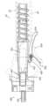
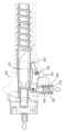
図8及び図9は、例示的な針発射アセンブリ(400)を示す。針発射アセンブリ(400)は、概して、プローブハウジング(22、24)に対して針アセンブリ(100)を手作業でコッキングし、発射するように構成される。以下により詳しく説明するように、針発射アセンブリ(400)は、概して、オペレータに針アセンブリ(100)を病変の下または回りに配置することを要求するのではなく、針アセンブリ(400)を標的病変または関心のある塊に直接的に発射するために使用することができる。針発射アセンブリ(400)は、コッキング部分(410)、トリップまたはリリース機構(420)、及び弾性部材またはコイルばね(450)を含む。8 and 9 show an exemplary needle firing assembly (400). The needle firing assembly (400) is generally configured to manually cock and fire the needle assembly (100) relative to the probe housings (22, 24). As described in more detail below, the needle firing assembly (400) can generally be used to fire the needle assembly (400) directly into a target lesion or mass of interest, rather than requiring an operator to position the needle assembly (100) under or around the lesion. The needle firing assembly (400) includes a cocking portion (410), a trip or release mechanism (420), and a resilient member or coil spring (450).
図8及び図9に最もよく示すように、コッキング部分(410)は、2つの横方向に延びるアーム(412)、及びキャッチ(414)(図9)を含む。本例では、コッキング部分(410)は、概してバルブアセンブリ(200)のマニホルド(210)の構造の中に統合されている。マニホルド(210)は、カニューレ(120)の近端部に固定されるため、コッキング部分(410)によるマニホルド(210)の移動または平行移動によって、カニューレ(120)の対応する移動または平行移動が行われることを理解されたい。本例のコッキング部分(410)は、マニホルド(210)の中に統合されているとして示されているが、他の例では、コッキング部分(410)を、マニホルド(210)とは無関係に、カニューレ(120)に取り付けられた完全に別個の構成要素として構成できることを理解されたい。As best seen in FIGS. 8 and 9, the cocking portion (410) includes two laterally extending arms (412) and a catch (414) (FIG. 9). In this example, the cocking portion (410) is generally integrated into the structure of the manifold (210) of the valve assembly (200). It should be understood that the manifold (210) is secured to the proximal end of the cannula (120), such that movement or translation of the manifold (210) by the cocking portion (410) results in a corresponding movement or translation of the cannula (120). While the cocking portion (410) in this example is shown as being integrated into the manifold (210), it should be understood that in other examples, the cocking portion (410) can be configured as a completely separate component attached to the cannula (120) independent of the manifold (210).
アーム(412)は、マニホルド(210)から横方向に延び、概してプローブハウジング(22、24)から突出する。以下により詳しく説明するように、アーム(412)は、概して、マニホルド(210)及び針アセンブリ(100)を近位に引っ張って、針発射アセンブリ(400)をコッキングするためのオペレータによる把持のために構成される。したがって、アーム(412)が種々の把持特徴を含む場合があることを理解されたい。例えば、本例では、アーム(412)は、把持を促進するためにわずかな湾曲を含む。他の例では、アームは、把持を促進するためにリブ及び/または複数の湾曲を含む場合がある。また、本例のアーム(412)は、グリッド状の構造から形成される。そのような構造は、流体排出に備えることによって滑りを防ぎ得る。言うまでもなく、そのような特徴は単に任意選択にすぎず、ソリッドアーム(412)を優先して、いくつかの例では省略し得る。Arm (412) extends laterally from manifold (210) and generally projects from probe housing (22, 24). As described in more detail below, arm (412) is generally configured for grasping by an operator to pull manifold (210) and needle assembly (100) proximally to cock needle firing assembly (400). It should be understood, therefore, that arm (412) may include a variety of gripping features. For example, in this example, arm (412) includes a slight curvature to facilitate grasping. In other examples, arm may include ribs and/or multiple curvatures to facilitate grasping. Also, arm (412) in this example is formed from a grid-like structure. Such a structure may provide for fluid evacuation and thus prevent slippage. Of course, such features are merely optional and may be omitted in some examples in favor of a solid arm (412).
図9に最もよく示すように、本例のキャッチ(414)は、マニホルド(210)の下側の開口部によって画定される。しかしながら、上述のように、そのような開口部も、カニューレ(120)に取り付けられた完全に別個の本体構成要素の中に組み込むことができる。それにも関わらず、キャッチ(414)は、遠位に向く壁(416)を含む。以下により詳しく説明するように、壁(416)は、概して、トリップ機構(420)と係合して、針発射アセンブリ(400)をコッキング位置にロックするように構成される。したがって、壁(416)は、トリップ機構の1つ以上の部分が上に係止するための概して平坦な表面を提供する。As best seen in FIG. 9, the catch (414) in this example is defined by an opening on the underside of the manifold (210). However, as noted above, such an opening may also be incorporated into an entirely separate body component attached to the cannula (120). Nevertheless, the catch (414) includes a distally facing wall (416). As described in more detail below, the wall (416) is generally configured to engage the trip mechanism (420) to lock the needle firing assembly (400) in a cocked position. Thus, the wall (416) provides a generally flat surface for one or more portions of the trip mechanism to latch onto.
図8に最もよく示すように、トリップ機構(420)は、ねじりばね(422)、アンカーピン(424)、及びリリースアーム(430)を含む。ねじりばねは、通常、アンカーピン(424)の周りに適合して、アンカーピン(424)の軸の周りでリリースアーム(430)をキャッチ(414)に向かって上向きに偏向させる。以下により詳しく説明するように、アンカーピン(424)は、プローブハウジング(22、24)の少なくとも一部分に固締して、軸の周りでのリリースアーム(430)の枢動を可能にするように構成される。As best seen in FIG. 8, the trip mechanism (420) includes a torsion spring (422), an anchor pin (424), and a release arm (430). The torsion spring typically fits around the anchor pin (424) to bias the release arm (430) upwardly toward the catch (414) about the axis of the anchor pin (424). As described in more detail below, the anchor pin (424) is configured to clamp to at least a portion of the probe housing (22, 24) to allow pivoting of the release arm (430) about the axis.
リリースアーム(430)は、ロック歯(432)、ピボットアーム(434)、及びロック歯(432)とピボットアーム(434)との間に配置されたピボット開口部(436)を含む。以下により詳しく説明するように、ロック歯(432)は、概して、キャッチ(414)の壁(416)と係合するように構成される。ピボットアーム(434)は、概して、プローブハウジング(22、24)の外部から延びて、オペレータがリリースアーム(430)を枢動させ、それによって針発射アセンブリ(400)を解除、トリガ、またはトリップすることを可能にするように構成される。ピボット開口部(436)は、アンカーピン(434)を受け入れて、リリースアーム(430)の枢動を可能にしつつも、ピボット軸の周りでリリースアーム(430)をロックするように構成される。The release arm (430) includes a locking tooth (432), a pivot arm (434), and a pivot opening (436) disposed between the locking tooth (432) and the pivot arm (434). As described in more detail below, the locking tooth (432) is generally configured to engage the wall (416) of the catch (414). The pivot arm (434) is generally configured to extend from the exterior of the probe housing (22, 24) to allow an operator to pivot the release arm (430) and thereby release, trigger, or trip the needle firing assembly (400). The pivot opening (436) is configured to receive an anchor pin (434) to lock the release arm (430) about the pivot axis while still allowing the release arm (430) to pivot.
本例のコイルばね(450)は、コッキング部分(410)を遠位位置に向かって偏向させるために使用される。コイルばね(450)は、本明細書ではコイルばねとして説明しているが、他の例では、ゴムバンド、弾性索もしくはワイヤ、または弾性棒などの種々の代替の弾力的な機構を使用できることを理解されたい。The coil spring (450) in this example is used to bias the cocking portion (410) toward a distal position. Although the coil spring (450) is described herein as a coil spring, it should be understood that in other examples, various alternative resilient mechanisms may be used, such as a rubber band, elastic cord or wire, or elastic rod.
針発射アセンブリ(400)の例示的な使用は、図10A~図11Cに示されている。針発射アセンブリ(400)を使用する前に、生検装置(10)を初期化し、生検処置のために準備することができる。例えば、このプロセスは、ホルスター(30)をプローブ(20)に取り付けることによって始まる場合がある。ホルスター(30)内の制御モジュール(1000)は、次に例えばカッター(60)を完全に閉じ、カッター(60)を完全に開き、次にカッター(60)を再び完全に閉じることを含む場合がある初期化シーケンスを開始する。An exemplary use of needle firing assembly (400) is shown in FIGS. 10A-11C. Prior to using needle firing assembly (400), biopsy device (10) may be initialized and prepared for a biopsy procedure. For example, this process may begin by attaching holster (30) to probe (20). Control module (1000) in holster (30) then initiates an initialization sequence that may include, for example, fully closing cutter (60), fully opening cutter (60), and then fully closing cutter (60) again.
初期化が完了すると、オペレータは、発射のために針発射アセンブリ(400)のコッキングを開始し得る。図10Aに示すように、オペレータは最初に(矢印で示すように)1つ以上のボタン(54)を押して、カッター(60)を開放位置に後退させ得る。この段階で、生検装置(10)は、コッキング手順のために準備される。オペレータは、次にコッキング部分(410)のアーム(412)を把持し、アーム(412)及びコッキング部分(410)をコイルばね(450)の弾性的な偏向に逆らって近位に引っ張り得る。図10Aに示すように、アーム(412)を近位に引っ張ると、針アセンブリ(100)の対応する近位の移動が生じる。Once initialization is complete, the operator may begin cocking the needle firing assembly (400) for firing. As shown in FIG. 10A, the operator may first press one or more buttons (54) (as indicated by the arrows) to retract the cutter (60) to the open position. At this stage, the biopsy device (10) is prepared for the cocking procedure. The operator may then grasp the arm (412) of the cocking portion (410) and pull the arm (412) and the cocking portion (410) proximally against the elastic bias of the coil spring (450). Pulling the arm (412) proximally results in a corresponding proximal movement of the needle assembly (100), as shown in FIG. 10A.
オペレータは、トリップ機構(420)が、コッキング部分(410)のキャッチ(414)と係合するまでアーム(412)を近位に引っ張り続ける場合がある。特に、図11A及び図11Bを比較することによって分かるように、コッキング部分(410)が近位に移動すると、キャッチ(414)は、リリースアーム(430)に対して近位に移動する。キャッチ(414)が、図11Bに示すようにリリースアーム(430)と位置合わせされると、ねじりばね(422)は、ロック歯(432)がキャッチ(414)の壁(416)と係合するまで、リリースアーム(430)をコッキング部分(410)に向かって上向きに偏向させる。この段階で、オペレータは、アーム(412)を解除することができ、針発射アセンブリ(400)は、針アセンブリ(100)の発射が所望されるまでコッキング位置に留まる。The operator may continue to pull the arm (412) proximally until the trip mechanism (420) engages the catch (414) of the cocking portion (410). As can be seen by comparing FIGS. 11A and 11B in particular, as the cocking portion (410) moves proximally, the catch (414) moves proximally relative to the release arm (430). When the catch (414) is aligned with the release arm (430) as shown in FIG. 11B, the torsion spring (422) biases the release arm (430) upward toward the cocking portion (410) until the locking tooth (432) engages the wall (416) of the catch (414). At this stage, the operator may release the arm (412) and the needle firing assembly (400) will remain in the cocked position until firing of the needle assembly (100) is desired.
針発射アセンブリ(400)がコッキングされると、オペレータは、図10Bに示すように、針アセンブリ(100)の一部分を患者に挿入し得る。図示しないが、この段階の前に、オペレータは、任意選択で1つ以上のボタン(54)を押して、カッター(60)を遠位位置に進め得ることも理解されたい。そのような使用は、組織を通る針アセンブリ(100)の貫通を促進するために望ましい場合がある。Once the needle firing assembly (400) is cocked, the operator may insert a portion of the needle assembly (100) into the patient, as shown in FIG. 10B. It should also be appreciated that, although not shown, prior to this step, the operator may optionally depress one or more buttons (54) to advance the cutter (60) to a distal position. Such use may be desirable to facilitate penetration of the needle assembly (100) through tissue.
それにも関わらず、針アセンブリ(100)が患者の中に挿入されると、オペレータは、画像誘導(例えば、超音波)の下で針アセンブリ(100)を患者内に配置して、組織貫通先端(140)を標的病変または塊に隣接して配置し得る。組織貫通先端(140)が所望されるように配置されると、オペレータは、次に針アセンブリ(100)を発射して、それによって組織貫通先端(140)を標的病変または塊を通して発射することを望む場合がある。Nonetheless, once the needle assembly (100) has been inserted into the patient, the operator may position the needle assembly (100) within the patient under image guidance (e.g., ultrasound) to position the tissue-piercing tip (140) adjacent to the target lesion or mass. Once the tissue-piercing tip (140) is positioned as desired, the operator may then wish to fire the needle assembly (100), thereby firing the tissue-piercing tip (140) through the target lesion or mass.
針アセンブリ(100)を発射するために、オペレータは、図10Cに示すように、リリースアーム(430)のピボットアーム(434)を近位にかつ上向きに引っ張り得る。図11Cに示すように、この移動により、ロック歯(432)がキャッチ(414)の壁(416)から離れて枢動し、それによって壁から外れるように、リリースアーム(430)は枢動する。ロック歯(432)が壁(416)から外れると、コイルばねの弾性的な偏向によって、コッキング部分(410)は遠位に押し付けられ、これによって針アセンブリ(100)の遠位の平行移動が生じる。To fire the needle assembly (100), the operator may pull the pivot arm (434) of the release arm (430) proximally and upwardly, as shown in FIG. 10C. This movement causes the release arm (430) to pivot such that the locking tooth (432) pivots away from, and thereby disengages from, the wall (416) of the catch (414), as shown in FIG. 11C. When the locking tooth (432) disengages from the wall (416), the elastic bias of the coil spring urges the cocking portion (410) distally, thereby causing distal translation of the needle assembly (100).
針アセンブリ(100)が発射されると、1つ以上のボタン(54)を押すことによってカッター(60)を使用し、横方向開口(150)を通して組織収集を実行できる。1つ以上の組織試料を収集し、組織試料ホルダー(40)に付着することができる。適切な数の組織試料が取得されると、針アセンブリ(100)を患者から引き出すことができる。組織試料は、次に病理研究室に送ることができ、プローブ(20)は処分することができ、ホルスター(30)は後続の処置のために洗浄及び/または滅菌することができる。Once the needle assembly (100) is fired, tissue collection can be performed through the lateral opening (150) using the cutter (60) by pressing one or more buttons (54). One or more tissue samples can be collected and attached to the tissue sample holder (40). Once an appropriate number of tissue samples have been obtained, the needle assembly (100) can be withdrawn from the patient. The tissue samples can then be sent to a pathology lab, the probe (20) can be disposed of, and the holster (30) can be cleaned and/or sterilized for subsequent procedures.
IV.例示的な代替針発射アセンブリ
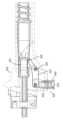
図12A及び図12Bは、例示的な代替針発射アセンブリ(500)を備えた生検装置(10)を示す。針発射アセンブリ(500)は、本明細書で明示的に断りのない限り、上述の針発射アセンブリ(400)に実質的に類似している。さらに、針発射アセンブリ(500)は、本明細書で明示的に断りがない場合を除き、上述の針発射アセンブリ(400)と実質的に同様に動作する。例えば、針発射アセンブリ(500)は、上述のコッキング部分(410)に実質的に類似しているコッキング部分(510)を含む。しかしながら、上述の針発射アセンブリ(400)とは異なり、本例の針発射アセンブリ(500)は、異なるトリップ機構(520)を使用する。分かるように、トリップ機構(520)は、通常、プッシュボタンリリース機構を含む。特に、トリップ機構(520)は、ロック歯(526)をコッキング部分(510)と係合させるために、ピボットピン(524)の周りで枢動可能である枢動レバーアーム(522)を含む。 IV. Exemplary Alternative Needle Firing Assembly FIGS. 12A and 12B show a biopsy device (10) with an exemplary alternative needle firing assembly (500). The needle firing assembly (500) is substantially similar to the needle firing assembly (400) described above, unless otherwise expressly stated herein. Moreover, the needle firing assembly (500) operates substantially similarly to the needle firing assembly (400) described above, unless otherwise expressly stated herein. For example, the needle firing assembly (500) includes a cocking portion (510) that is substantially similar to the cocking portion (410) described above. However, unlike the needle firing assembly (400) described above, the needle firing assembly (500) of this example uses a different trip mechanism (520). As can be seen, the trip mechanism (520) typically includes a push button release mechanism. In particular, trip mechanism (520) includes a pivoting lever arm (522) that is pivotable about a pivot pin (524) to engage a locking tooth (526) with the cocking portion (510).
レバーアーム(522)の末端部は、プッシュボタン(530)に枢着されている。プッシュボタン(530)は、広がった下端(532)を含む。ばね(540)は、プローブハウジング(22、24)と下端(532)との間に配置されて、プッシュボタン(530)を横方向に外向きにまたは下向きに弾性的に偏向させる。この弾性的な偏向によって、レバーアーム(522)の末端部も下向きに偏向し、その結果ロック歯(526)は、上述のロック歯(432)と同様に上向きに偏向する。The distal end of the lever arm (522) is pivotally attached to a push button (530). The push button (530) includes an enlarged lower end (532). A spring (540) is disposed between the probe housing (22, 24) and the lower end (532) to resiliently bias the push button (530) laterally outwardly or downwardly. This resiliently biases the distal end of the lever arm (522) downwardly, which in turn biases the locking tooth (526) upwardly, similar to the locking tooth (432) described above.
使用中、針発射アセンブリ(500)は、上述した針発射アセンブリ(400)と実質的に同様に使用される。例えば、針発射アセンブリ(400)と同様に、針発射アセンブリ(500)は、コッキング部分(510)を近位に引っ張ることによってコッキングされる。これによって、コッキング部分(510)は、ロック歯(526)の弾性的な偏向によって適切な距離まで近位に引っ張られると、コッキング部分(510)と係合する。しかしながら、針発射アセンブリ(400)とは異なり、針発射アセンブリ(500)は、図12Bに示されるレバー機構よりむしろプッシュボタン(530)を介して発射される。In use, the needle firing assembly (500) is used in a substantially similar manner to the needle firing assembly (400) described above. For example, like the needle firing assembly (400), the needle firing assembly (500) is cocked by pulling the cocking portion (510) proximally, which engages the cocking portion (510) when it is pulled proximally an appropriate distance by the resilient deflection of the locking teeth (526). However, unlike the needle firing assembly (400), the needle firing assembly (500) is fired via a push button (530) rather than the lever mechanism shown in FIG. 12B.
参照により本明細書に組み込まれると言われている任意の特許、刊行物または他の開示資料は、全部または一部において、組み込まれる資料が本開示に記載の既存の定義、記述または他の開示資料と矛盾しない範囲でのみ、本明細書に組み込まれることを理解されたい。したがって、また必要な範囲で、本明細書に明確に記載された開示は、参照により本明細書に組み込まれた任意の相反する資料に優先する。参照により本明細書に組み込まれると言われているが、本明細書に記載されている既存の定義、記述もしくは他の開示資料と矛盾する任意の資料またはその一部は、その組み込まれた資料と既存の開示資料との間に矛盾が生じない範囲でのみ組み込まれる。Any patent, publication, or other disclosure material that is said to be incorporated by reference herein is understood to be incorporated herein, in whole or in part, only to the extent that the incorporated material does not conflict with existing definitions, descriptions or other disclosure material set forth in this disclosure. Thus, and to the extent necessary, the disclosure as expressly set forth herein takes precedence over any conflicting material incorporated herein by reference. Any material, or portion thereof, that is said to be incorporated by reference herein but that conflicts with existing definitions, descriptions or other disclosure material set forth herein is incorporated only to the extent that no conflict arises between the incorporated material and the existing disclosure material.
本明細書に開示される装置の実施形態は、単回使用後に廃棄されるように設計される場合もあれば、それらは複数回使用されるように設計される場合もある。実施形態は、いずれの場合または両方の場合に、少なくとも1回の使用後に再利用するために再調整され得る。再調整は、装置の分解、続いて特定の部品の洗浄または交換、及び後続の再組立てのステップの任意の組み合わせを含み得る。特に、装置の実施形態は分解し得、装置の任意の数の特定の部品またはパーツは、任意の組み合わせで選択的に交換または取り外し得る。特定のパーツの洗浄及び/または交換時、装置の実施形態は、再調整施設において、または外科処置の直前に外科チームによってのどちらかの後続の使用のために再組立てし得る。当業者は、装置の再調整では、分解、洗浄/交換、及び再組立ての様々な技術を利用し得ることを理解する。そのような技術を用いること及び結果として得られる再調整された装置は、すべて本出願の範囲内である。Embodiments of the devices disclosed herein may be designed to be disposed of after a single use, or they may be designed to be used multiple times. Embodiments, in either or both cases, may be reconditioned for reuse after at least one use. Reconditioning may include any combination of the steps of disassembly of the device, followed by cleaning or replacement of particular parts, and subsequent reassembly. In particular, embodiments of the device may be disassembled, and any number of the particular parts or parts of the device may be selectively replaced or removed in any combination. Upon cleaning and/or replacement of particular parts, embodiments of the device may be reassembled for subsequent use either at a reconditioning facility, or by a surgical team immediately prior to a surgical procedure. One skilled in the art will appreciate that reconditioning of a device may utilize a variety of techniques for disassembly, cleaning/replacement, and reassembly. The use of such techniques and the resulting reconditioned device are all within the scope of the present application.
ほんの一例として、本明細書で説明する実施形態は外科手術の前に処理してもよい。最初に、新しいかまたは使用済みの器具を取得して、必要に応じて洗浄してもよい。次に器具を滅菌してもよい。1つの滅菌技術では、器具をプラスチックまたはTYVEKバッグなどの閉鎖及びシールした容器内に置く。次に容器及び器具を、容器に侵入することができる放射線場(たとえば、ガンマ線、X線、または高エネルギー電子)の中に置いてもよい。放射線が器具上及び容器内のバクテリアを殺す場合がある。滅菌された器具を次に、滅菌容器に保管してもよい。シールされた容器は、医療設備で開かれるまで、器具を滅菌状態に保ち得る。また、装置は、ベータ線もしくはガンマ線、エチレンオキシド、または蒸気を含むが、これに限定されない当該技術分野で知られる任意の他の技術を用いて滅菌し得る。By way of example only, the embodiments described herein may be processed prior to a surgical procedure. First, new or used instruments may be obtained and cleaned if necessary. The instruments may then be sterilized. In one sterilization technique, the instruments are placed in a closed and sealed container, such as a plastic or TYVEK bag. The container and instruments may then be placed in a radiation field (e.g., gamma radiation, x-rays, or high energy electrons) that can penetrate the container. The radiation may kill bacteria on the instruments and in the container. The sterilized instruments may then be stored in a sterile container. The sealed container may keep the instruments sterile until they are opened in the medical facility. The device may also be sterilized using any other technique known in the art, including, but not limited to, beta or gamma radiation, ethylene oxide, or steam.
V.例示的な組み合わせ
以下の実施例は、本明細書の教示が組み合わされ得るまたは適用され得る、種々の非包括的な方法に関する。以下の実施例は、本出願または本出願の後続の出願の任意の時点で提示され得る、任意の特許請求の範囲の適用範囲を制限するためのものではないことを理解すべきである。権利放棄は意図していない。以下の実施例は、単に例示的な目的で示しているにすぎない。本明細書の種々の教示を他の多くの方法で配置及び適用し得ることは、想到されている。いくつかの変形例が、以下の実施例で言及される特定の構成要素を省略してもよいことも想到されている。したがって、後で発明者によって、または対象となる発明者の後継者によって、特に明白に示されていない限り、下記に言及される態様または特徴のいずれも重大なものとみなすべきではない。本出願または本出願に関連する後続の出願にて、以下で言及する以外の更なる特徴を含む、何らかの特許請求の範囲が示された場合、これらの更なる特徴は、特許性に関係する何らかの理由で追加されたものと推定するものではない。 V. Exemplary Combinations The following examples relate to various non-exhaustive ways in which the teachings herein may be combined or applied. It should be understood that the following examples are not intended to limit the scope of any claims that may be presented at any time in this application or any subsequent application of this application. No disclaimer is intended. The following examples are presented for illustrative purposes only. It is contemplated that the various teachings herein may be arranged and applied in many other ways. It is also contemplated that some variations may omit certain components referred to in the following examples. Thus, unless specifically and explicitly indicated by the inventor later or by the intended successor of the inventor, none of the aspects or features referred to below should be considered critical. If any claim is presented in this application or any subsequent application related to this application that includes additional features other than those referred to below, these additional features should not be presumed to have been added for any reason related to patentability.
実施例1
超音波誘導の下で使用するための生検装置であって、前記生検装置は、プローブと、前記プローブから延びる針と、前記針の中に配置されたカッターであって、カッター内腔を画定し、前記カッターの外部と前記針の内部との間にベント内腔を少なくとも部分的に画定する前記カッターと、キャッチ及びリリースを含む手動作動式針発射アセンブリであって、前記キャッチが前記針と同軸であり、前記針を発射するために弾性的に偏向し、前記リリースが前記キャッチと係合して、それによって前記キャッチをコッキング位置に保持するように構成される前記手動作動式針発射アセンブリとを備える、前記生検装置。 Example 1
1. A biopsy device for use under ultrasound guidance comprising: a probe; a needle extending from the probe; a cutter disposed within the needle, the cutter defining a cutter lumen and at least partially defining a vent lumen between an exterior of the cutter and an interior of the needle; and a manually actuated needle firing assembly including a catch and a release, the catch being coaxial with the needle and resiliently biased to fire the needle, and the release configured to engage the catch, thereby holding the catch in a cocked position.
実施例2
前記リリースは、前記キャッチとの係合に及び前記キャッチとの係合から枢動するように構成された枢動可能なアームを含む、実施例1に記載の生検装置。 Example 2
2. The biopsy device of example 1, wherein the release includes a pivotable arm configured to pivot into and out of engagement with the catch.
実施例3
前記リリースは、ロック歯を前記キャッチと係合させ、切り離すように構成されたプッシュボタンを含む、実施例1に記載の生検装置。 Example 3
The biopsy device of example 1, wherein the release includes a push button configured to engage and disengage a locking tooth from the catch.
実施例4
前記カッターの移動に応えて、通気状態と密封状態との間で前記ベント内腔を遷移させるように構成されたベントアセンブリをさらに備える、実施例1~3のいずれか1つ以上に記載の生検装置。 Example 4
The biopsy device of any one or more of Examples 1-3, further comprising a vent assembly configured to transition the vent lumen between a vented state and a sealed state in response to movement of the cutter.
実施例5
前記キャッチは、前記ベントアセンブリの少なくとも一部分と一体である、実施例4に記載の生検装置。 Example 5
The biopsy device of example 4, wherein the catch is integral with at least a portion of the vent assembly.
実施例6
前記ベントアセンブリは、マニホルドと、前記マニホルド内で移動可能なスプール本体とを含み、前記キャッチが前記マニホルドと一体である、実施例5に記載の生検装置。 Example 6
6. The biopsy device of example 5, wherein the vent assembly includes a manifold and a spool body movable within the manifold, and the catch is integral with the manifold.
実施例7
前記キャッチは前記マニホルド内のくぼみによって画定され、前記くぼみは遠位に向く壁を画定する、実施例6に記載の生検装置。 Example 7
The biopsy device of example 6, wherein the catch is defined by a recess in the manifold, the recess defining a distally facing wall.
実施例8
前記リリースは前記遠位に向く壁と係合して、前記針発射アセンブリを前記コッキング位置に選択的にロックするように構成される、実施例7に記載の生検装置。 Example 8
The biopsy device of example 7, wherein the release is configured to engage the distally facing wall to selectively lock the needle firing assembly in the cocked position.
実施例9
カッター駆動アセンブリをさらに備え、前記カッター駆動アセンブリは、前記カッターと同軸の第1のギア及び第2のギアを含み、前記第1のギア及び前記第2のギアは異なる回転速度で同時に回転して、前記カッターを平行移動及び回転させるように構成される、実施例1~8のいずれか1つ以上に記載の生検装置。 Example 9
A biopsy device described in any one or more of Examples 1 to 8, further comprising a cutter drive assembly including a first gear and a second gear coaxial with the cutter, the first gear and the second gear configured to rotate simultaneously at different rotational speeds to translate and rotate the cutter.
実施例10
前記カッターと連通する組織試料ホルダーをさらに備え、前記組織試料ホルダーは、前記組織試料ホルダーの中に画定されたチャンバ内で複数の組織試料を収集するように構成される、実施例1~9のいずれか1つ以上に記載の生検装置。 Example 10
A biopsy device described in any one or more of Examples 1 to 9, further comprising a tissue sample holder in communication with the cutter, the tissue sample holder configured to collect multiple tissue samples within a chamber defined in the tissue sample holder.
実施例11
1つ以上の組織試料を収集するために生検装置を使用するための方法であって、コッキングアームを近位に手動で後退させ、それによって前記生検装置のハウジングに対して針を近位に後退させることと、前記針をコッキング位置に保持するために前記コッキングアームと関連するキャッチを係止することと、前記針を患者の組織に挿入することと、前記針を標的病変に隣接して配置することと、前記針を前記標的病変の中に発射することとを含む、前記方法。 Example 11
1. A method for using a biopsy device to collect one or more tissue samples, the method comprising: manually retracting a cocking arm proximally, thereby retracting a needle proximally relative to a housing of the biopsy device; engaging a catch associated with the cocking arm to hold the needle in a cocked position; inserting the needle into a patient's tissue; positioning the needle adjacent to a target lesion; and firing the needle into the target lesion.
実施例12
前記コッキングアームを手動で後退させる前に前記生検装置を初期化することをさらに含む、実施例11に記載の方法。 Example 12
12. The method of example 11, further comprising initializing the biopsy device before manually retracting the cocking arm.
実施例13
前記生検装置を初期化する前記ステップは、前記針内に配置されたカッターを閉鎖位置に前進させ、後に前記カッターを開放位置に後退させ、後に前記カッターを前記閉鎖位置に戻すことを含む、実施例12に記載の方法。 Example 13
13. The method of example 12, wherein the step of initializing the biopsy device includes advancing a cutter disposed within the needle to a closed position, subsequently retracting the cutter to an open position, and subsequently returning the cutter to the closed position.
実施例14
前記生検装置を初期化した後、及び前記的コッキングアームを手動で後退させる前に、前記カッターを前記開放位置に後退させることをさらに含む、実施例13に記載の方法。 Example 14
14. The method of example 13, further comprising retracting the cutter to the open position after initializing the biopsy device and before manually retracting the target cocking arm.
実施例15
超音波誘導の下で使用するための生検装置であって、プローブと、前記プローブから延びる針と、前記針の中に配置されたカッターであって、カッター内腔を画定し、前記カッターの外部と前記針の内部との間にベント内腔を少なくとも部分的に画定する前記カッターと、前記カッターの移動に応えて通気状態と密封状態との間で前記ベント内腔を遷移させるように構成されたベントアセンブリと、キャッチ及びリリースを含む手動作動式針発射アセンブリであって、前記キャッチが前記針を発射するために弾性的に偏向し、前記キャッチの少なくとも一部分が前記ベントアセンブリと一体であり、前記リリースが前記キャッチと係合して、それによって前記キャッチをコッキング位置に保持するように構成される前記手動作動式針発射アセンブリとを備える、前記生検装置。 Example 15
1. A biopsy device for use under ultrasound guidance comprising: a probe; a needle extending from the probe; a cutter disposed within the needle, the cutter defining a cutter lumen and at least partially defining a vent lumen between an exterior of the cutter and an interior of the needle; a vent assembly configured to transition the vent lumen between a vented state and a sealed state in response to movement of the cutter; and a manually actuated needle firing assembly including a catch and a release, the catch resiliently deflectable to fire the needle, at least a portion of the catch being integral with the vent assembly, and the release configured to engage the catch to thereby hold the catch in a cocked position.
実施例16
前記リリースは、前記キャッチとの係合に及び前記キャッチとの係合から枢動するように構成された枢動可能なアームを含む、実施例15に記載の生検装置。 Example 16
16. The biopsy device of example 15, wherein the release includes a pivotable arm configured to pivot into and out of engagement with the catch.
実施例17
前記リリースは、ロック歯を前記キャッチと係合させ、切り離すように構成されたプッシュボタンを含む、実施例15に記載の生検装置。 Example 17
The biopsy device of example 15, wherein the release includes a push button configured to engage and disengage a locking tooth from the catch.
実施例18
前記ベントアセンブリは、マニホルドと、前記マニホルド内で移動可能なスプール本体とを含み、前記キャッチは前記マニホルドと一体である、実施例15に記載の生検装置。 Example 18
16. The biopsy device of example 15, wherein the vent assembly includes a manifold and a spool body movable within the manifold, and the catch is integral with the manifold.
実施例19
前記キャッチは前記マニホルド内のくぼみによって画定され、前記くぼみは遠位に向く壁を画定する、実施例18に記載の生検装置。 Example 19
19. The biopsy device of example 18, wherein the catch is defined by a recess in the manifold, the recess defining a distally facing wall.
実施例20
前記リリースは前記遠位に向く壁と係合して、前記針発射アセンブリを前記コッキング位置に選択的にロックするように構成される、実施例19に記載の生検装置。 Example 20
20. The biopsy device of example 19, wherein the release is configured to engage the distally facing wall to selectively lock the needle firing assembly in the cocked position.
実施例21
カッター駆動アセンブリをさらに備え、前記カッター駆動アセンブリは、前記カッターと同軸の第1のギア及び第2のギアを含み、前記第1のギア及び前記第2のギアは異なる回転速度で同時に回転して、前記カッターを平行移動及び回転させるように構成される、実施例15~20のいずれか1つ以上に記載の生検装置。 Example 21
A biopsy device described in any one or more of Examples 15 to 20, further comprising a cutter drive assembly including a first gear and a second gear coaxial with the cutter, the first gear and the second gear configured to rotate simultaneously at different rotational speeds to translate and rotate the cutter.
実施例22
前記カッターと連通する組織試料ホルダーをさらに備え、前記組織試料ホルダーが、前記組織試料ホルダーの中に画定されたチャンバ内で複数の組織試料を収集するように構成される、実施例15~21のいずれか1つ以上に記載の生検装置。 Example 22
A biopsy device described in any one or more of Examples 15 to 21, further comprising a tissue sample holder in communication with the cutter, the tissue sample holder configured to collect multiple tissue samples within a chamber defined in the tissue sample holder.
本発明の種々の実施形態について図示し、説明したが、本明細書で説明した方法及びシステムの更なる適応が、当業者による適切な変更により、本発明の範囲を逸脱することなく達成され得る。そのような可能な修正形態のうちのいくつかに言及したが、他のものは当業者には明らかであろう。例えば、前に議論した実施例、実施形態、幾何学的形状、材料、寸法、比率、工程などは、例示的なものであり、必須ではない。したがって、本発明の範囲は以下の特許請求の範囲に関して考慮すべきであり、明細書及び図面で図示し、説明した構造及び動作の詳細には限定されないことが理解される。Although various embodiments of the present invention have been shown and described, further adaptations of the methods and systems described herein may be achieved by those skilled in the art through appropriate modifications without departing from the scope of the present invention. Some of such possible modifications have been mentioned, but others will be apparent to those skilled in the art. For example, the examples, embodiments, geometries, materials, dimensions, proportions, steps, etc. discussed above are illustrative and not required. Accordingly, it is understood that the scope of the present invention should be considered in terms of the following claims, and is not limited to the details of construction and operation shown and described in the specification and drawings.
〔実施の態様〕
(1) 生検装置であって、
(a)プローブと、
(b)前記プローブから延びる針と、
(c)前記針の中に配置されたカッターであって、カッター内腔を画定し、前記カッターの外部と前記針の内部との間にベント内腔を少なくとも部分的に画定する、前記カッターと、
(d)キャッチ及びリリースを含む手動作動式針発射アセンブリであって、前記キャッチが前記針と同軸であり、前記針を発射するために弾性的に偏向し、前記リリースが、前記キャッチと係合し、それによって前記キャッチをコッキング位置に保持するように構成される、前記手動作動式針発射アセンブリと
を備える、前記生検装置。
(2) 前記リリースが、前記キャッチとの係合に及び前記キャッチとの係合から枢動するように構成された枢動可能なアームを含む、実施態様1に記載の生検装置。
(3) 前記リリースが、ロック歯を前記キャッチと係合させ、切り離すように構成されたプッシュボタンを含む、実施態様1に記載の生検装置。
(4) 前記カッターの移動に応えて、通気状態と密封状態との間で前記ベント内腔を遷移させるように構成されたベントアセンブリをさらに備える、実施態様1~3のいずれか1つ以上に記載の生検装置。
(5) 前記キャッチが、前記ベントアセンブリの少なくとも一部分と一体である、実施態様4に記載の生検装置。[Embodiment]
(1) A biopsy device comprising:
(a) a probe;
(b) a needle extending from the probe;
(c) a cutter disposed within the needle, the cutter defining a cutter lumen and at least partially defining a vent lumen between an exterior of the cutter and an interior of the needle;
(d) a manually actuated needle firing assembly including a catch and a release, the catch being coaxial with the needle and resiliently biased to fire the needle, and the release configured to engage the catch, thereby retaining the catch in a cocked position.
2. The biopsy device of
3. The biopsy device of
(4) The biopsy device of any one or more of
5. The biopsy device of
(6) 前記ベントアセンブリが、マニホルドと、前記マニホルド内で移動可能なスプール本体とを含み、前記キャッチが前記マニホルドと一体である、実施態様5に記載の生検装置。
(7) 前記キャッチが前記マニホルド内のくぼみによって画定され、前記くぼみが遠位に向く壁を画定する、実施態様6に記載の生検装置。
(8) 前記リリースが前記遠位に向く壁と係合して、前記針発射アセンブリを前記コッキング位置に選択的にロックするように構成される、実施態様7に記載の生検装置。
(9) カッター駆動アセンブリをさらに備え、前記カッター駆動アセンブリが、前記カッターと同軸の第1のギア及び第2のギアを含み、前記第1のギア及び前記第2のギアが異なる回転速度で同時に回転して、前記カッターを平行移動及び回転させるように構成される、実施態様1~8のいずれか1つ以上に記載の生検装置。
(10) 前記カッターと連通する組織試料ホルダーをさらに備え、前記組織試料ホルダーが、前記組織試料ホルダーの中に画定されたチャンバ内で複数の組織試料を収集するように構成される、実施態様1~9のいずれか1つ以上に記載の生検装置。6. The biopsy device of claim 5, wherein the vent assembly includes a manifold and a spool body movable within the manifold, and the catch is integral with the manifold.
7. The biopsy device of
8. The biopsy device of claim 7, wherein the release is configured to engage the distally facing wall to selectively lock the needle firing assembly in the cocked position.
(9) The biopsy device according to any one or more of
10. The biopsy device of any one or more of claims 1-9, further comprising a tissue sample holder in communication with the cutter, the tissue sample holder configured to collect a plurality of tissue samples within a chamber defined therein.
(11) 超音波誘導の下で使用するための生検装置であって、
(a)プローブと、
(b)前記プローブから延びる針と、
(c)前記針の中に配置されたカッターであって、カッター内腔を画定し、前記カッターの外部と前記針の内部との間にベント内腔を少なくとも部分的に画定する、前記カッターと、
(d)前記カッターの移動に応えて、通気状態と密封状態との間で前記ベント内腔を遷移させるように構成されたベントアセンブリと、
(e)キャッチ及びリリースを含む手動作動式針発射アセンブリであって、前記キャッチが前記針を発射するために弾性的に偏向し、前記キャッチの少なくとも一部分が前記ベントアセンブリと一体であり、前記リリースが、前記キャッチと係合し、それによって前記キャッチをコッキング位置に保持するように構成される、前記手動作動式針発射アセンブリと
を備える、前記生検装置。
(12) 前記リリースが、前記キャッチとの係合に及び前記キャッチとの係合から枢動するように構成された枢動可能なアームを含む、実施態様11に記載の生検装置。
(13) 前記リリースが、ロック歯を前記キャッチと係合させ、切り離すように構成されたプッシュボタンを含む、実施態様11に記載の生検装置。
(14) 前記ベントアセンブリが、マニホルドと、前記マニホルド内で移動可能なスプール本体とを含み、前記キャッチが前記マニホルドと一体である、実施態様11に記載の生検装置。
(15) 前記キャッチが前記マニホルド内のくぼみによって画定され、前記くぼみが遠位に向く壁を画定する、実施態様14に記載の生検装置。(11) A biopsy device for use under ultrasound guidance, comprising:
(a) a probe;
(b) a needle extending from the probe;
(c) a cutter disposed within the needle, the cutter defining a cutter lumen and at least partially defining a vent lumen between an exterior of the cutter and an interior of the needle;
(d) a vent assembly configured to transition the vent lumen between a vented state and a sealed state in response to movement of the cutter;
(e) a manually actuated needle firing assembly including a catch and a release, the catch resiliently biased to fire the needle, at least a portion of the catch integral with the vent assembly, and the release configured to engage the catch thereby retaining the catch in a cocked position.
12. The biopsy device of claim 11, wherein the release includes a pivotable arm configured to pivot into and out of engagement with the catch.
13. The biopsy device of claim 11, wherein the release includes a push button configured to engage and disengage a locking tooth from the catch.
14. The biopsy device of claim 11, wherein the vent assembly includes a manifold and a spool body movable within the manifold, and the catch is integral with the manifold.
15. The biopsy device of claim 14, wherein the catch is defined by a recess in the manifold, the recess defining a distally facing wall.
(16) 前記リリースが前記遠位に向く壁と係合して、前記針発射アセンブリを前記コッキング位置に選択的にロックするように構成される、実施態様15に記載の生検装置。
(17) 1つ以上の組織試料を収集するために生検装置を使用するための方法であって
(a)コッキングアームを近位に手動で後退させて、それによって前記生検装置のハウジングに対して針を近位に後退させることと、
(b)前記針をコッキング位置に保持するために前記コッキングアームと関連するキャッチを係止することと、
(c)前記針を患者の組織に挿入することと、
(d)前記針を標的病変に隣接して配置することと、
(e)前記針を前記標的病変の中に発射することと
を含む、前記方法。
(18) 前記コッキングアームを手動で後退させる前に前記生検装置を初期化することをさらに含む、実施態様17に記載の方法。
(19) 前記生検装置を初期化する前記ステップが、前記針内に配置されたカッターを閉鎖位置に前進させ、後に前記カッターを開放位置に後退させ、後に前記カッターを前記閉鎖位置に戻すことを含む、実施態様18に記載の方法。
(20) 前記生検装置を初期化した後、及び前記コッキングアームを手動で後退させる前に、前記カッターを前記開放位置に後退させることをさらに含む、実施態様19に記載の方法。16. The biopsy device of claim 15, wherein the release is configured to engage the distally facing wall to selectively lock the needle firing assembly in the cocked position.
(17) A method for using a biopsy device to collect one or more tissue samples, comprising: (a) manually retracting a cocking arm proximally, thereby retracting a needle proximally relative to a housing of the biopsy device;
(b) locking a catch associated with the cocking arm to retain the needle in a cocked position; and
(c) inserting the needle into tissue of a patient;
(d) positioning the needle adjacent to a target lesion;
(e) firing the needle into the target lesion.
18. The method of claim 17, further comprising initializing the biopsy device before manually retracting the cocking arm.
19. The method of claim 18, wherein the step of initializing the biopsy device includes advancing a cutter disposed within the needle to a closed position, subsequently retracting the cutter to an open position, and subsequently returning the cutter to the closed position.
20. The method of claim 19, further comprising retracting the cutter to the open position after initializing the biopsy device and before manually retracting the cocking arm.
Claims (13)
Translated fromJapanese(a)プローブと、
(b)前記プローブから延びる針部分と、
(c)前記針部分の中に配置されたカッターであって、カッター内腔を画定し、前記カッターの外部と前記針部分の内部との間に第2の内腔部分を少なくとも部分的に画定する、前記カッターと、
(d)キャッチ及びトリップ機構を含む手動作動式針発射アセンブリであって、前記キャッチが前記針部分と同軸であり、前記トリップ機構が、前記針部分を発射するために弾性的な偏向に逆らって前記キャッチと係合し、それによって前記キャッチをコッキング位置に保持するように構成される、前記手動作動式針発射アセンブリと
を備え、
前記カッターの移動に応えて、通気状態と密封状態との間で前記第2の内腔部分を遷移させるように構成されたバルブアセンブリをさらに備え、
前記バルブアセンブリが、マニホルドと、前記マニホルド内で移動可能なスプール本体とを含み、前記キャッチが前記マニホルドと一体であり、
前記キャッチが前記マニホルドの下側の開口部又は前記マニホルド内のくぼみによって画定され、前記くぼみが遠位に向く壁を画定する、前記生検装置。 1. A biopsy device comprising:
(a) a probe;
(b) a needle portion extending from the probe;
(c) a cutter disposed within the needle portion, the cutter defining a cutter lumen and at least partially defining a second lumen portion between an exterior of the cutter and an interior of the needle portion;
(d) a manually operated needle firing assembly including a catch and a trip mechanism, the catch being coaxial with the needle portion, and the trip mechanism configured to engage the catch against a resilient bias to fire the needleportion , thereby retaining the catch in a cocked position;
a valve assembly configured to transition the second lumen portion between a vented state and a sealed state in response to movement of the cutter;
the valve assembly includes a manifold and a spool body movable within the manifold, the catch being integral with the manifold;
The biopsy device, wherein the catch is defined by an opening on the underside of the manifold or a recess in the manifold, the recess defining a distally facing wall.
(a)プローブと、
(b)前記プローブから延びる針部分と、
(c)前記針部分の中に配置されたカッターであって、カッター内腔を画定し、前記カッターの外部と前記針部分の内部との間に第2の内腔部分を少なくとも部分的に画定する、前記カッターと、
(d)前記カッターの移動に応えて、通気状態と密封状態との間で前記第2の内腔部分を遷移させるように構成されたバルブアセンブリと、
(e)キャッチ及びトリップ機構を含む手動作動式針発射アセンブリであって、前記キャッチの少なくとも一部分が前記バルブアセンブリと一体であり、前記トリップ機構が、前記針部分を発射するために弾性的な偏向に逆らって前記キャッチと係合し、それによって前記キャッチをコッキング位置に保持するように構成される、前記手動作動式針発射アセンブリと
を備え、
前記バルブアセンブリが、マニホルドと、前記マニホルド内で移動可能なスプール本体とを含み、前記キャッチが前記マニホルドと一体であり、
前記キャッチが前記マニホルドの下側の開口部又は前記マニホルド内のくぼみによって画定され、前記くぼみが遠位に向く壁を画定する、前記生検装置。 1. A biopsy device for use under ultrasound guidance, comprising:
(a) a probe;
(b) a needle portion extending from the probe;
(c) a cutter disposed within the needle portion, the cutter defining a cutter lumen and at least partially defining a second lumen portion between an exterior of the cutter and an interior of the needle portion;
(d) a valve assembly configured to transition the second lumen portion between a vented state and a sealed state in response to movement of the cutter;
(e) a manually operated needle firing assembly including a catch and a trip mechanism, at least a portion of the catch being integral with the valve assembly, the trip mechanism being configured to engage the catch against a resilient bias to fire the needleportion , thereby retaining the catch in a cocked position;
the valve assembly includes a manifold and a spool body movable within the manifold, the catch being integral with the manifold;
The biopsy device, wherein the catch is defined by an opening on the underside of the manifold or a recess in the manifold, the recess defining a distally facing wall.
Applications Claiming Priority (3)
| Application Number | Priority Date | Filing Date | Title |
|---|---|---|---|
| US201862769956P | 2018-11-20 | 2018-11-20 | |
| US62/769,956 | 2018-11-20 | ||
| PCT/US2019/062161WO2020106691A2 (en) | 2018-11-20 | 2019-11-19 | Biopsy device with manual firing mechanism |
Publications (2)
| Publication Number | Publication Date |
|---|---|
| JP2022507743A JP2022507743A (en) | 2022-01-18 |
| JP7539883B2true JP7539883B2 (en) | 2024-08-26 |
Family
ID=68835377
Family Applications (1)
| Application Number | Title | Priority Date | Filing Date |
|---|---|---|---|
| JP2021527212AActiveJP7539883B2 (en) | 2018-11-20 | 2019-11-19 | Biopsy device with manual firing mechanism |
Country Status (6)
| Country | Link |
|---|---|
| US (1) | US20210267578A1 (en) |
| EP (1) | EP3883479B1 (en) |
| JP (1) | JP7539883B2 (en) |
| CN (1) | CN113164166A (en) |
| PL (1) | PL3883479T3 (en) |
| WO (1) | WO2020106691A2 (en) |
Families Citing this family (4)
| Publication number | Priority date | Publication date | Assignee | Title |
|---|---|---|---|---|
| CA3146564A1 (en)* | 2019-08-07 | 2021-02-11 | Jason May | Bi-planar instrument for bone cutting and joint realignment procedure |
| US11912541B2 (en)* | 2020-05-08 | 2024-02-27 | Search And Recovery Engineering LLC | Rapid recovery grapple |
| CN116636884A (en)* | 2023-05-31 | 2023-08-25 | 重庆西山科技股份有限公司 | Single motor power handle and biopsy device |
| CN117503221B (en)* | 2024-01-04 | 2024-04-02 | 泓欣科创生物科技(北京)有限公司 | Blood vessel puncher |
Citations (5)
| Publication number | Priority date | Publication date | Assignee | Title |
|---|---|---|---|---|
| JP2003111762A (en) | 2001-10-05 | 2003-04-15 | Tasuku:Kk | Biopsy needle device |
| JP2006192267A (en) | 2005-01-10 | 2006-07-27 | Ethicon Endo Surgery Inc | Biopsy instrument with improved needle penetration |
| JP2011005248A (en) | 2009-06-12 | 2011-01-13 | Ethicon Endo Surgery Inc | Tetherless biopsy device with reusable portion |
| JP2013544574A (en) | 2010-11-01 | 2013-12-19 | デビコー・メディカル・プロダクツ・インコーポレイテッド | Handheld biopsy device with needle firing |
| JP2017500089A (en) | 2013-11-25 | 2017-01-05 | デビコー・メディカル・プロダクツ・インコーポレイテッドDevicor Medical Products, Inc. | Biopsy device with translational valve assembly |
Family Cites Families (14)
| Publication number | Priority date | Publication date | Assignee | Title |
|---|---|---|---|---|
| US4958625A (en)* | 1989-07-18 | 1990-09-25 | Boston Scientific Corporation | Biopsy needle instrument |
| US5526822A (en) | 1994-03-24 | 1996-06-18 | Biopsys Medical, Inc. | Method and apparatus for automated biopsy and collection of soft tissue |
| US6086544A (en) | 1999-03-31 | 2000-07-11 | Ethicon Endo-Surgery, Inc. | Control apparatus for an automated surgical biopsy device |
| US6602203B2 (en) | 2000-10-13 | 2003-08-05 | Ethicon Endo-Surgery, Inc. | Remote thumbwheel for a surgical biopsy device |
| US6626849B2 (en) | 2001-11-01 | 2003-09-30 | Ethicon Endo-Surgery, Inc. | MRI compatible surgical biopsy device |
| US8357103B2 (en)* | 2003-10-14 | 2013-01-22 | Suros Surgical Systems, Inc. | Vacuum assisted biopsy needle set |
| US20060074345A1 (en) | 2004-09-29 | 2006-04-06 | Hibner John A | Biopsy apparatus and method |
| US20120283563A1 (en)* | 2011-05-03 | 2012-11-08 | Moore Kyle P | Biopsy device with manifold alignment feature and tissue sensor |
| US9345457B2 (en) | 2006-12-13 | 2016-05-24 | Devicor Medical Products, Inc. | Presentation of biopsy sample by biopsy device |
| US7854706B2 (en) | 2007-12-27 | 2010-12-21 | Devicor Medical Products, Inc. | Clutch and valving system for tetherless biopsy device |
| US20100152610A1 (en) | 2008-12-16 | 2010-06-17 | Parihar Shailendra K | Hand Actuated Tetherless Biopsy Device with Pistol Grip |
| WO2012033796A2 (en) | 2010-09-10 | 2012-03-15 | Devicor Medical Products, Inc. | Biopsy device tissue sample holder with removable tray |
| US8622926B2 (en)* | 2011-05-23 | 2014-01-07 | Devicor Medical Products, Inc. | Tetherless biopsy device |
| US8801742B2 (en) | 2011-06-01 | 2014-08-12 | Devicor Medical Products, Inc. | Needle assembly and blade assembly for biopsy device |
- 2019
- 2019-11-19JPJP2021527212Apatent/JP7539883B2/enactiveActive
- 2019-11-19WOPCT/US2019/062161patent/WO2020106691A2/ennot_activeCeased
- 2019-11-19PLPL19817544.0Tpatent/PL3883479T3/enunknown
- 2019-11-19EPEP19817544.0Apatent/EP3883479B1/enactiveActive
- 2019-11-19CNCN201980076334.8Apatent/CN113164166A/enactivePending
- 2021
- 2021-05-19USUS17/324,324patent/US20210267578A1/enactivePending
Patent Citations (5)
| Publication number | Priority date | Publication date | Assignee | Title |
|---|---|---|---|---|
| JP2003111762A (en) | 2001-10-05 | 2003-04-15 | Tasuku:Kk | Biopsy needle device |
| JP2006192267A (en) | 2005-01-10 | 2006-07-27 | Ethicon Endo Surgery Inc | Biopsy instrument with improved needle penetration |
| JP2011005248A (en) | 2009-06-12 | 2011-01-13 | Ethicon Endo Surgery Inc | Tetherless biopsy device with reusable portion |
| JP2013544574A (en) | 2010-11-01 | 2013-12-19 | デビコー・メディカル・プロダクツ・インコーポレイテッド | Handheld biopsy device with needle firing |
| JP2017500089A (en) | 2013-11-25 | 2017-01-05 | デビコー・メディカル・プロダクツ・インコーポレイテッドDevicor Medical Products, Inc. | Biopsy device with translational valve assembly |
Also Published As
| Publication number | Publication date |
|---|---|
| EP3883479A2 (en) | 2021-09-29 |
| CN113164166A (en) | 2021-07-23 |
| PL3883479T3 (en) | 2024-11-04 |
| EP3883479B1 (en) | 2024-06-26 |
| WO2020106691A2 (en) | 2020-05-28 |
| WO2020106691A3 (en) | 2020-07-23 |
| JP2022507743A (en) | 2022-01-18 |
| US20210267578A1 (en) | 2021-09-02 |
Similar Documents
| Publication | Publication Date | Title |
|---|---|---|
| JP7539883B2 (en) | Biopsy device with manual firing mechanism | |
| KR101857945B1 (en) | Biopsy device with motorized needle firing | |
| US8864682B2 (en) | Clutch and valving system for tetherless biopsy device | |
| EP2412314B1 (en) | Vacuum sensor and pressure pump for tetherless biopsy device | |
| EP3073933B1 (en) | Biopsy device with translating valve assembly | |
| JP2010000353A (en) | Biopsy devices with universal probe | |
| EP2814399A1 (en) | Biopsy device valve assembly | |
| CN113194841B (en) | Biopsy device with translating shuttle valve assembly | |
| US20210275156A1 (en) | Needle rotation mechanism for biopsy needle | |
| HK1222109B (en) | Biopsy device with translating valve assembly | |
| JP2025514026A (en) | Biopsy device with integrated dither feature - Patent Application 20070229633 | |
| HK1166684B (en) | Vacuum sensor and pressure pump for tetherless biopsy device |
Legal Events
| Date | Code | Title | Description |
|---|---|---|---|
| A621 | Written request for application examination | Free format text:JAPANESE INTERMEDIATE CODE: A621 Effective date:20221109 | |
| A977 | Report on retrieval | Free format text:JAPANESE INTERMEDIATE CODE: A971007 Effective date:20230703 | |
| A131 | Notification of reasons for refusal | Free format text:JAPANESE INTERMEDIATE CODE: A131 Effective date:20230829 | |
| A601 | Written request for extension of time | Free format text:JAPANESE INTERMEDIATE CODE: A601 Effective date:20231129 | |
| A521 | Request for written amendment filed | Free format text:JAPANESE INTERMEDIATE CODE: A523 Effective date:20231222 | |
| A131 | Notification of reasons for refusal | Free format text:JAPANESE INTERMEDIATE CODE: A131 Effective date:20240312 | |
| A521 | Request for written amendment filed | Free format text:JAPANESE INTERMEDIATE CODE: A523 Effective date:20240604 | |
| TRDD | Decision of grant or rejection written | ||
| A01 | Written decision to grant a patent or to grant a registration (utility model) | Free format text:JAPANESE INTERMEDIATE CODE: A01 Effective date:20240806 | |
| A61 | First payment of annual fees (during grant procedure) | Free format text:JAPANESE INTERMEDIATE CODE: A61 Effective date:20240814 | |
| R150 | Certificate of patent or registration of utility model | Ref document number:7539883 Country of ref document:JP Free format text:JAPANESE INTERMEDIATE CODE: R150 |