JP7539683B2 - Aircraft - Google Patents
AircraftDownload PDFInfo
- Publication number
- JP7539683B2 JP7539683B2JP2019552634AJP2019552634AJP7539683B2JP 7539683 B2JP7539683 B2JP 7539683B2JP 2019552634 AJP2019552634 AJP 2019552634AJP 2019552634 AJP2019552634 AJP 2019552634AJP 7539683 B2JP7539683 B2JP 7539683B2
- Authority
- JP
- Japan
- Prior art keywords
- section
- wing
- flying
- aircraft
- propeller
- Prior art date
- Legal status (The legal status is an assumption and is not a legal conclusion. Google has not performed a legal analysis and makes no representation as to the accuracy of the status listed.)
- Active
Links
Images


Classifications
- B—PERFORMING OPERATIONS; TRANSPORTING
- B64—AIRCRAFT; AVIATION; COSMONAUTICS
- B64C—AEROPLANES; HELICOPTERS
- B64C27/00—Rotorcraft; Rotors peculiar thereto
- B64C27/04—Helicopters
- B64C27/08—Helicopters with two or more rotors
- B—PERFORMING OPERATIONS; TRANSPORTING
- B64—AIRCRAFT; AVIATION; COSMONAUTICS
- B64C—AEROPLANES; HELICOPTERS
- B64C29/00—Aircraft capable of landing or taking-off vertically, e.g. vertical take-off and landing [VTOL] aircraft
- B64C29/02—Aircraft capable of landing or taking-off vertically, e.g. vertical take-off and landing [VTOL] aircraft having its flight directional axis vertical when grounded
Landscapes
- Engineering & Computer Science (AREA)
- Aviation & Aerospace Engineering (AREA)
- Mechanical Engineering (AREA)
- Toys (AREA)
Description
Translated fromJapanese本発明は、飛行体に関し、特に、推力部と翼部とが変位可能に接続されるものに関する。The present invention relates to an aircraft, in particular one in which a thrust section and a wing section are displaceably connected.
ローター(回転翼)と主翼を備えた航空機として、所謂ティルトロータ方式及びティルトウイング方式の2つの方式が知られている。There are two known types of aircraft equipped with rotors (rotating wings) and main wings: the so-called tilt rotor type and the tilt wing type.
特許文献1には、主翼は本体部に固定されており、モータを含むローター全体が垂直方向及び飛行方向の範囲で変位可能に構成されている航空機が開示されている(ティルトロータ方式)。
一方、特許文献2には、主翼と本体部とが垂直方向及び飛行方向の範囲で変位可能に構成されており、モータ及びロータ全体は主翼に固定されている航空機が開示されている(ティルトウイング方式)。On the other hand,
特許文献1の技術によれば、上昇時において主翼がプロペラ後流の広範囲に入ることから主翼に飛行効率が悪い。According to the technology of
特許文献2の技術によれば、主翼全体が変位することから風の抵抗を受けたりと不安定である。According to the technology in
本発明は、上記事情に鑑みてなされたものであり、ホバリングから水平飛行への効率的かつ安全な移行を可能にした飛行体を提供する。The present invention has been made in consideration of the above circumstances, and provides an aircraft that enables an efficient and safe transition from hovering to horizontal flight.
本発明によれば、
翼部と当該翼部に設けられた回転翼とを備える飛行部と、
機体部とを備え、
前記翼部は、
少なくとも進行方向に対して負の迎角を維持可能となるように構成される、
飛行体が得られる。 According to the present invention,
a flying section including a wing section and a rotor provided on the wing section;
A body part;
The wing portion is
Configured to be able to maintain at least a negative angle of attack relative to the direction of travel;
You get a flying object.
この発明によれば、ホバリングから水平飛行への効率的かつ安全な移行を可能にした飛行体を提供することができる。This invention makes it possible to provide an aircraft that enables an efficient and safe transition from hovering to horizontal flight.
本実施の形態による発明は、以下の構成を備える。
[項目1]
翼部と当該翼部に設けられた回転翼とを備える飛行部と、
機体部とを備え、
前記翼部は、
少なくとも進行方向に対して負の迎角を維持可能となるように構成される、
飛行体。
[項目2]
項目1に記載の飛行体であって、
前記翼部は、
少なくともホバリング時において前記回転翼の回転中心軸に対して負の迎角を維持可能となるように構成される、
飛行体。
[項目3]
項目1又は項目2に記載の飛行体であって、
前記機体部と独立変位可能な搭乗部を備える、
飛行体。
[項目4]
項目3に記載の飛行体であって、
前記機体部は、飛行方向に対して水平かつ垂直に延び、
前記搭乗部は、側面視において、前記機体部の略中央に設けられている、
飛行体。 The present invention according to this embodiment has the following configuration.
[Item 1]
a flying section including a wing section and a rotor provided on the wing section;
A body part;
The wing portion is
Configured to be able to maintain at least a negative angle of attack relative to the direction of travel;
Flying vehicle.
[Item 2]
The wing portion is
The rotor is configured to be capable of maintaining a negative angle of attack with respect to a rotation central axis of the rotor at least during hovering.
Flying vehicle.
[Item 3]
The flying object according to
A boarding section that can be displaced independently of the aircraft body section is provided.
Flying vehicle.
[Item 4]
Item 3. The flying object according to item 3,
The fuselage section extends horizontally and vertically relative to a direction of flight,
The boarding section is provided at approximately the center of the aircraft body section in a side view.
Flying vehicle.
次に、図を参照して、本発明の実施の形態による飛行体について説明する。Next, with reference to the figures, an air vehicle according to an embodiment of the present invention will be described.
<構造>
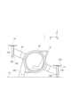
図1に示されるように、本実施の形態による飛行体1は、概略、飛行部10と、機体部20と、搭乗部30と、を備えている。飛行部10は、翼部100と、モータ102と、プロペラ(回転翼)104とを備えている。翼部100は、少なくともホバリング時においてプロペラ104の回転中心軸に対して負の迎角を維持可能となるように構成され、機体部20に対して固定される。固定方法は、公知の種々の方法を採用できる。また、機体部20(及び当該機体部20に固定された飛行部10)と、搭乗部30とは独立変位可能に構成されている。<Structure>
As shown in FIG. 1, the
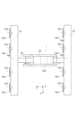
図2に示されるように、本実施の形態による飛行体1は、上から見た場合にH字形状を有している。即ち、飛行体1は、前後に設けられた2つの飛行部10と、これらを接続する機体部20(及び搭乗部30)とを備えている。As shown in Figure 2, the
上述したように、飛行部10は、翼部100と、モータ102と、プロペラ104とを備えている。なお。以下の説明においては、図におけるX軸、Y軸及びZ軸と、方向との対応は次の通り対応する。
X軸:第1水平方向(+X方向:左、-X方向:右)
Y軸:第2水平方向(+Y方向:前、-Y方向:後)
Z軸:垂直方向(+Z方向:上、-Z方向:下) As described above, the
X-axis: 1st horizontal direction (+X direction: left, -X direction: right)
Y-axis: 2nd horizontal direction (+Y direction: front, -Y direction: rear)
Z axis: Vertical direction (+Z direction: top, -Z direction: bottom)
翼部100は、X方向に延びており、モータ102によって揚力を発生させる部位である。初期状態(図1に示される状態)では、前縁が上、後縁が下を向いている。翼部100は、前側の翼部100と後側の翼部100とで構成されている。The
推力発生部10は、プロペラ(推力発生部)104を回転させることにより推力発生部10から前方への推進力を生みだす。The
モータ102は、エンジン等により置換することが可能である。プロペラ104は、モータ102によって駆動可能であり、時計方向に及び/または反時計方向に、モータ102の回転軸(例えば、モータの長軸)の周りに回転する。The
本実施の形態おいて、モータ102は、プロペラ104を、すべて同一方向に回転可能であるし、独立して回転することも可能である。プロペラ104のいくつかは一方の方向に回転し、他のプロペラ104は他方方向に回転する。プロペラ104を構成するブレードは、同一回転数ですべて回転することも可能であり、夫々異なる回転数で回転することも可能である。回転数は移動体の寸法(例えば、大きさ、重さ)や制御状態(速さ、移動方向等)に基づいて自動又は手動により定めることができる。In this embodiment, the
プロペラ104は、モータ102からの出力を受けて回転する。プロペラ104が回転することによって、飛行体1を地面Gから離陸させ、水平移動させ、目的地に着陸させるための推進力が発生する。なお、プロペラ104は、右方向への回転、停止及び左方向への回転が可能である。The
本発明のプロペラ104は、ブレードは細長い形状を有している。任意のブレード(回転子)の数(例えば、1、2、3、4、またはそれ以上のブレード)でよい。また、ブレードの形状は、平らな形状、曲がった形状、よじれた形状、テーパ形状、またはそれらの組み合わせ等の任意の形状が可能である。The
なお、ブレードの形状は変化可能である(例えば、伸縮、折りたたみ、折り曲げ等)。ブレードは対称的(同一の上部及び下部表面を有する)または非対称的(異なる形状の上部及び下部表面を有する)であってもよい。It should be noted that the shape of the blade can vary (e.g., extend, fold, bend, etc.). The blade can be symmetric (having identical upper and lower surfaces) or asymmetric (having upper and lower surfaces of different shapes).
ブレードはエアホイル、ウイング、またはブレードが空中を移動される時に動的空気力(例えば、揚力、推力)を生成するために好適な幾何学形状に形成可能である。ブレードの幾何学形状は、揚力及び推力を増加させ、抗力を削減する等の、ブレードの動的空気特性を最適化するために適宜選択可能である。The blade can be formed into a suitable geometry to generate aerodynamic forces (e.g., lift, thrust) as the airfoil, wing, or blade is moved through the air. The blade geometry can be selected to optimize the aerodynamic properties of the blade, such as increasing lift and thrust and reducing drag.
機体部20は、前側の翼部100の中央から後方に延びており、後側の翼部100の中央に接続されている。The
本実施の形態による機体部20は、カーボン、ステンレス、アルミニウム、マグネシウム等またはこれらの合金又は組合わせ等から適宜選択される素材で形成することが可能である。The
機体部20は、搭乗部30を包含する略環状の収容部を有している。収容部は、機体部20の略中央付近に設けられている。The
搭乗部30は、収容部の形状に対応する略環状の形状を有しており、収容部の内側に位置している。搭乗部30と収容部とは、略環状の周方向に独立変位可能に構成されている。The
<飛行形態>
続いて、図3及び図4を参照して、飛行時の形態及び変形について説明する。 <Flight mode>
Next, the configuration and deformation during flight will be described with reference to FIG. 3 and FIG.
本実施の形態によるプロペラ104は、翼部100の前縁よりも前に設けられている。図1に示される着陸状態において、翼部100の前縁を上方に向けると共に、モータユニットが少なくとも上方向への推進力を生じる向きとされている。脚部202と後側翼部(及びモータ102)は、着陸時に飛行体1を支える部位として機能する。In this embodiment, the
図3に示されるように、飛行体1の上昇時及びホバリング時においては、翼部100は、プロペラ104の回転中心軸に対して負の迎角となっている。この際、前側のプロペラ104も後側のプロペラ104もプロペラ104の回転中心軸に対して負の迎角となる。3, when the
図3及び図4に示されるように、垂直離陸(図3)から水平移動(図4)へ移行する際に、機体部20が、図の両矢印のように、周方向に変位することにより、水平姿勢から前傾姿勢へと変位する。この際、搭乗部30は、同じ方向を向いたままとなる。As shown in Figures 3 and 4, when moving from vertical takeoff (Figure 3) to horizontal movement (Figure 4), the
図4に示されるように、水平移動時においても、翼部100は、プロペラ104の回転中心軸に対して負の迎角となっている。この際、前側のプロペラ104も後側のプロペラ104もプロペラ104の回転中心軸に対して負の迎角となる。この際、前側のプロペラ104も後側のプロペラ104もプロペラ104の回転中心軸に対して負の迎角となる。As shown in Figure 4, even during horizontal movement, the
図5は、翼型の揚力・抵抗特性を示したグラフである。図5の横軸は、迎え角を示し、縦軸は、抵抗係数及び揚力係数を示す。図5より明らかなように、マイナスの迎角の方が、プラスの迎角よりも抵抗係数が小さいことがわかる。また、仮に、マイナス6度の迎角で機体を製作すると、ゼロ迎角の機体と同等の主翼の揚力が得られることがわかる。このように、翼部100をプロペラ104の回転中心軸に対して負の迎角とすると、プロペラ後流の抗力を押さえつつ、翼部100の過剰な迎角を控えることが可能になる。Figure 5 is a graph showing the lift and resistance characteristics of an airfoil. The horizontal axis of Figure 5 shows the angle of attack, and the vertical axis shows the drag coefficient and lift coefficient. As is clear from Figure 5, a negative angle of attack has a smaller drag coefficient than a positive angle of attack. It can also be seen that if an aircraft is manufactured with an angle of attack of minus 6 degrees, the same lift force of the main wing can be obtained as with an aircraft with a zero angle of attack. In this way, by making the
したがって、本実施形態の飛行体によれば、ホバリング時から水平飛行移行へと安全に移行することができる。Therefore, the aircraft of this embodiment can safely transition from hovering to horizontal flight.
<一般的構造>
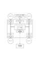
図6は、本発明の飛行体の機能ブロック図である。上述した飛行体は、例えば、図6に示されるような構成を有していてもよい。<General Structure>
6 is a functional block diagram of the flying object of the present invention. The flying object described above may have a configuration as shown in FIG.
フライトコントローラは、プログラマブルプロセッサ(例えば、中央演算処理装置(CPU))などの1つ以上のプロセッサを有することができる。The flight controller may have one or more processors, such as a programmable processor (e.g., a central processing unit (CPU)).
フライトコントローラは、図示しないメモリを有しており、当該メモリにアクセス可能である。メモリは、1つ以上のステップを行うためにフライトコントローラが実行可能であるロジック、コード、および/またはプログラム命令を記憶している。The flight controller has accessible memory (not shown) that stores logic, code, and/or program instructions that the flight controller can execute to perform one or more steps.
メモリは、例えば、SDカードやランダムアクセスメモリ(RAM)などの分離可能な媒体または外部の記憶装置を含んでいてもよい。カメラやセンサ類から取得したデータは、メモリに直接に伝達されかつ記憶されてもよい。例えば、カメラ等で撮影した静止画・動画データが内蔵メモリ又は外部メモリに記録される。The memory may include, for example, a separable medium such as an SD card or random access memory (RAM) or an external storage device. Data acquired from a camera or sensor may be directly transmitted to and stored in the memory. For example, still image and video data captured by a camera or the like is recorded in the built-in memory or an external memory.
フライトコントローラは、飛行体の状態を制御するように構成された制御モジュールを含んでいる。例えば、制御モジュールは、6自由度(並進運動x、y及びz、並びに回転運動θx、θy及びθz)を有する飛行体の空間的配置、速度、および/または加速度を調整するために飛行体の推進機構(モータ等)を制御する。制御モジュールは、搭載部、センサ類の状態のうちの1つ以上を制御することができる。 The flight controller includes acontrol module configured to control the state of the air vehicle. For example, the control module controls the propulsion mechanisms (e.g., motors) of the air vehicle to regulate the spatial orientation, velocity, and/or acceleration of the air vehicle having six degrees of freedom (translational motion x, y, and z, and rotational motion θx , θ y, and θz ). The control module can control one or more of the states of the payload and sensors.
フライトコントローラは、1つ以上の外部のデバイス(例えば、端末、表示装置、または他の遠隔の制御器)からのデータを送信および/または受け取るように構成された送受信部と通信可能である。送受信機は、有線通信または無線通信などの任意の適当な通信手段を使用することができる。The flight controller can communicate with a transceiver configured to transmit and/or receive data from one or more external devices (e.g., a terminal, a display device, or other remote control). The transceiver can use any suitable communication means, such as wired or wireless communication.
例えば、送受信部は、ローカルエリアネットワーク(LAN)、ワイドエリアネットワーク(WAN)、赤外線、無線、WiFi、ポイントツーポイント(P2P)ネットワーク、電気通信ネットワーク、クラウド通信などのうちの1つ以上を利用することができる。For example, the transceiver may utilize one or more of a local area network (LAN), a wide area network (WAN), infrared, radio, WiFi, a point-to-point (P2P) network, a telecommunications network, cloud communications, and the like.
送受信部は、センサ類で取得したデータ、フライトコントローラが生成した処理結果、所定の制御データ、端末または遠隔の制御器からのユーザコマンドなどのうちの1つ以上を送信および/または受け取ることができる。The transceiver unit can transmit and/or receive one or more of the following: data acquired by sensors, processing results generated by the flight controller, specified control data, user commands from a terminal or a remote controller, etc.
本実施の形態によるセンサ類は、慣性センサ(加速度センサ、ジャイロセンサ)、GPSセンサ、近接センサ(例えば、ライダー)、またはビジョン/イメージセンサ(例えば、カメラ)を含み得る。The sensors in this embodiment may include inertial sensors (accelerometers, gyro sensors), GPS sensors, proximity sensors (e.g., lidar), or vision/image sensors (e.g., cameras).
本発明の飛行体は、中長距離における宅配業務専用の飛行体としての利用、及び広域の監視業務、山岳領域の偵察・救助業務における産業用の飛行体としての利用が期待できる。また、本発明の飛行体は、マルチコプター・ドローン等の飛行機関連産業において利用することができ、さらに、本発明に、カメラ等を搭載し空撮任務も遂行可能な飛行体としても好適に使用することができる他、セキュリティ分野、農業、インフラ監視等の様々な産業にも利用することができる。The aircraft of the present invention is expected to be used as an aircraft dedicated to medium- to long-distance delivery services, and as an industrial aircraft for wide-area surveillance services and reconnaissance and rescue services in mountainous areas. The aircraft of the present invention can also be used in the aircraft-related industry, such as multicopters and drones, and can also be suitably used as an aircraft equipped with a camera or the like to perform aerial photography missions, and can also be used in various industries, such as the security field, agriculture, and infrastructure surveillance.
上述した実施の形態は、本発明の理解を容易にするための例示に過ぎず、本発明を限定して解釈するためのものではない。本発明は、その趣旨を逸脱することなく、変更、改良することができると共に、本発明にはその均等物が含まれることは言うまでもない。The above-described embodiment is merely an example for facilitating understanding of the present invention, and is not intended to limit the present invention. The present invention can be modified and improved without departing from the spirit of the invention, and it goes without saying that the present invention includes equivalents.
上述した実施の形態では、本発明の飛行体を有人の飛行体に適用する例を示した。しかし、これに限らない。本発明の飛行体を無人の飛行体に適用してもよい。In the above-described embodiment, an example was shown in which the aircraft of the present invention is applied to a manned aircraft. However, this is not limited to this. The aircraft of the present invention may also be applied to an unmanned aircraft.
上述した実施の形態では、翼部100が、少なくともホバリング時において前記回転翼の回転中心軸に対して負の迎角を維持可能となるように構成される例を示した。しかし、これに限らない。翼部100は、少なくとも進行方向に対して負の迎角を維持可能となるように構成されていればよい。In the above-described embodiment, an example has been shown in which the
1 飛行体
10 飛行部
100 翼部
102 モータ
104 プロペラ(回転翼)
20 機体部
30 搭乗部
20
Claims (4)
Translated fromJapanese前記飛行部が設けられる機体部と、を備え、
前記翼部は、前記プロペラのプロペラ後流を受ける位置に設けられ、
前記翼部は、少なくとも水平移動時において、当該翼部に設けられて回転する全ての前記プロペラの回転中心軸に沿って発生する気流の方向に対して負の迎角を維持するように構成される、
飛行体。 A flying section including a wing section and a plurality of motors and propellers provided on the wing section;
a body sectionin which the flying section is provided,
The blade portion is provided at a position to receive a propeller wake of the propeller,
The wing portion is configured to maintain a negative angle of attack with respect to a direction of an airflow generated along a central axis of rotation of all the propellers provided on the wing portion and rotating, at least during horizontal movement.
Flying vehicle.
側面視において、前記機体部の略中央に収容部を備える、
飛行体。 2. The flying object according to claim 1,
In a side view, a storage section is provided at approximately the center of the body section.
Flying vehicle.
前記飛行部が設けられる機体部と、を備え、
前記翼部は、前記プロペラのプロペラ後流を受ける位置に設けられる飛行体の飛行方法であって、
前記翼部が、少なくとも水平移動時において、当該翼部に設けられて回転する全ての前記プロペラの回転中心軸に沿って発生する気流の方向に対して負の迎角を維持するように飛行する、
飛行方法。 a flying section including a wing section and a plurality of motors and propellers provided on the wing section;
a body section inwhichthe flying section is provided,
A flying method for an aircraft, the wing portion being provided at a position receiving a propeller wake of the propeller , comprising:
The wing portion flies so as to maintain a negative angle of attack with respect to the direction of airflow generated along the central rotation axes of all the propellers provided on the wing portion and rotating, at least during horizontal movement.
How to fly.
前記飛行部が設けられる機体部と、を備え、
前記翼部は、前記プロペラのプロペラ後流を受ける位置に設けられる飛行体を制御するプログラムであって、
前記翼部が、少なくとも水平移動時において、当該翼部に設けられて回転する全ての前記プロペラの回転中心軸に沿って発生する気流の方向に対して負の迎角を維持するように前記飛行体を飛行させる、
プログラム。
a flying section including a wing section and a plurality of motors and propellers provided on the wing section;
a body section inwhichthe flying section is provided,
The wing unit is a program for controlling an aircraft provided at a position receiving a propeller wake of the propeller ,
The aircraft is flown so that the wing portion maintains a negative angle of attack with respect to a direction of an airflow generated along a central axis of rotation of all the propellers provided on the wing portion and rotating, at least during horizontal movement.
program.
Priority Applications (1)
| Application Number | Priority Date | Filing Date | Title |
|---|---|---|---|
| JP2024129189AJP2024149697A (en) | 2019-09-19 | 2024-08-05 | Aircraft |
Applications Claiming Priority (1)
| Application Number | Priority Date | Filing Date | Title |
|---|---|---|---|
| PCT/JP2019/036728WO2021053786A1 (en) | 2019-09-19 | 2019-09-19 | Aerial vehicle |
Related Child Applications (1)
| Application Number | Title | Priority Date | Filing Date |
|---|---|---|---|
| JP2024129189ADivisionJP2024149697A (en) | 2019-09-19 | 2024-08-05 | Aircraft |
Publications (2)
| Publication Number | Publication Date |
|---|---|
| JPWO2021053786A1 JPWO2021053786A1 (en) | 2021-03-25 |
| JP7539683B2true JP7539683B2 (en) | 2024-08-26 |
Family
ID=74884439
Family Applications (2)
| Application Number | Title | Priority Date | Filing Date |
|---|---|---|---|
| JP2019552634AActiveJP7539683B2 (en) | 2019-09-19 | 2019-09-19 | Aircraft |
| JP2024129189APendingJP2024149697A (en) | 2019-09-19 | 2024-08-05 | Aircraft |
Family Applications After (1)
| Application Number | Title | Priority Date | Filing Date |
|---|---|---|---|
| JP2024129189APendingJP2024149697A (en) | 2019-09-19 | 2024-08-05 | Aircraft |
Country Status (3)
| Country | Link |
|---|---|
| JP (2) | JP7539683B2 (en) |
| CN (1) | CN114502464A (en) |
| WO (1) | WO2021053786A1 (en) |
Citations (3)
| Publication number | Priority date | Publication date | Assignee | Title |
|---|---|---|---|---|
| JP2009113779A (en) | 2007-11-06 | 2009-05-28 | Hirobumi Seki | Multi-functional flight vehicle, and method and device for automatically maneuvering the same |
| US20180257761A1 (en) | 2016-07-01 | 2018-09-13 | Bell Helicopter Textron Inc. | Aircraft having Single-Axis Gimbal Mounted Propulsion Systems |
| WO2019056053A1 (en) | 2017-09-22 | 2019-03-28 | AMSL Innovations Pty Ltd | Wing tilt actuation system for electric vertical take-off and landing (vtol) aircraft |
Family Cites Families (8)
| Publication number | Priority date | Publication date | Assignee | Title |
|---|---|---|---|---|
| US3439888A (en)* | 1966-12-30 | 1969-04-22 | Boeing Co | Aircraft propulsion mounting arrangement |
| WO2010026517A2 (en)* | 2008-09-02 | 2010-03-11 | Urban Aeronautics Ltd. | Vtol vehicle with coaxially tilted or tiltable rotors |
| JP6108077B2 (en)* | 2013-01-29 | 2017-04-05 | 株式会社Ihi | Vertical take-off and landing aircraft |
| GB2540169B (en)* | 2015-07-08 | 2018-08-08 | Ge Aviation Systems Llc | Aircraft wing shaped to counter aerodynamic effects of propeller wake |
| US10513332B2 (en)* | 2015-10-05 | 2019-12-24 | Sikorsky Aircraft Corporation | Tiltwing aircraft |
| US10513334B2 (en)* | 2017-06-12 | 2019-12-24 | Textron Innovations Inc. | X-tiltwing aircraft |
| US11117657B2 (en)* | 2018-01-19 | 2021-09-14 | Aerhart, LLC | Aeronautical apparatus |
| GB2570342A (en)* | 2018-01-23 | 2019-07-24 | Ul Hussan Sulaman Shahzad | Airborne urban mobility vehicle |
- 2019
- 2019-09-19JPJP2019552634Apatent/JP7539683B2/enactiveActive
- 2019-09-19WOPCT/JP2019/036728patent/WO2021053786A1/ennot_activeCeased
- 2019-09-19CNCN201980100835.5Apatent/CN114502464A/enactivePending
- 2024
- 2024-08-05JPJP2024129189Apatent/JP2024149697A/enactivePending
Patent Citations (3)
| Publication number | Priority date | Publication date | Assignee | Title |
|---|---|---|---|---|
| JP2009113779A (en) | 2007-11-06 | 2009-05-28 | Hirobumi Seki | Multi-functional flight vehicle, and method and device for automatically maneuvering the same |
| US20180257761A1 (en) | 2016-07-01 | 2018-09-13 | Bell Helicopter Textron Inc. | Aircraft having Single-Axis Gimbal Mounted Propulsion Systems |
| WO2019056053A1 (en) | 2017-09-22 | 2019-03-28 | AMSL Innovations Pty Ltd | Wing tilt actuation system for electric vertical take-off and landing (vtol) aircraft |
Also Published As
| Publication number | Publication date |
|---|---|
| CN114502464A (en) | 2022-05-13 |
| JP2024149697A (en) | 2024-10-18 |
| WO2021053786A1 (en) | 2021-03-25 |
| JPWO2021053786A1 (en) | 2021-03-25 |
Similar Documents
| Publication | Publication Date | Title |
|---|---|---|
| US11639221B2 (en) | Flying vehicle and flying method therefor | |
| US12377977B2 (en) | Manned aircraft | |
| JP2018203226A (en) | Flight vehicle | |
| JP2025126222A (en) | flying object | |
| JP7584168B2 (en) | Manned aircraft | |
| JP7438523B2 (en) | Aircraft and flight methods for aircraft | |
| JP6993711B2 (en) | Flying objects and flying methods of flying objects | |
| JP2023076742A (en) | Flying body | |
| JP7539683B2 (en) | Aircraft | |
| JP7711909B2 (en) | Aircraft | |
| JP7398790B2 (en) | flying object | |
| CN116981619A (en) | Aircraft with a plurality of aircraft body | |
| JP7244955B2 (en) | Aircraft and flight method of the aircraft | |
| JP7153351B2 (en) | Airplane flight method | |
| CN218258694U (en) | Flying body | |
| JP6758697B2 (en) | Aircraft and how to fly | |
| JP7417244B2 (en) | flying object | |
| JPWO2021070363A1 (en) | Aircraft |
Legal Events
| Date | Code | Title | Description |
|---|---|---|---|
| A621 | Written request for application examination | Free format text:JAPANESE INTERMEDIATE CODE: A621 Effective date:20220909 | |
| A131 | Notification of reasons for refusal | Free format text:JAPANESE INTERMEDIATE CODE: A131 Effective date:20230302 | |
| A521 | Request for written amendment filed | Free format text:JAPANESE INTERMEDIATE CODE: A523 Effective date:20230425 | |
| A131 | Notification of reasons for refusal | Free format text:JAPANESE INTERMEDIATE CODE: A131 Effective date:20230727 | |
| A521 | Request for written amendment filed | Free format text:JAPANESE INTERMEDIATE CODE: A523 Effective date:20230920 | |
| A131 | Notification of reasons for refusal | Free format text:JAPANESE INTERMEDIATE CODE: A131 Effective date:20231102 | |
| A521 | Request for written amendment filed | Free format text:JAPANESE INTERMEDIATE CODE: A523 Effective date:20231227 | |
| A131 | Notification of reasons for refusal | Free format text:JAPANESE INTERMEDIATE CODE: A131 Effective date:20240222 | |
| A521 | Request for written amendment filed | Free format text:JAPANESE INTERMEDIATE CODE: A523 Effective date:20240422 | |
| TRDD | Decision of grant or rejection written | ||
| A01 | Written decision to grant a patent or to grant a registration (utility model) | Free format text:JAPANESE INTERMEDIATE CODE: A01 Effective date:20240711 | |
| A61 | First payment of annual fees (during grant procedure) | Free format text:JAPANESE INTERMEDIATE CODE: A61 Effective date:20240806 | |
| R150 | Certificate of patent or registration of utility model | Ref document number:7539683 Country of ref document:JP Free format text:JAPANESE INTERMEDIATE CODE: R150 |