JP7539602B2 - Guidewires and Catheter Management Devices - Google Patents
Guidewires and Catheter Management DevicesDownload PDFInfo
- Publication number
- JP7539602B2 JP7539602B2JP2022559731AJP2022559731AJP7539602B2JP 7539602 B2JP7539602 B2JP 7539602B2JP 2022559731 AJP2022559731 AJP 2022559731AJP 2022559731 AJP2022559731 AJP 2022559731AJP 7539602 B2JP7539602 B2JP 7539602B2
- Authority
- JP
- Japan
- Prior art keywords
- opening
- proximal
- slit
- centimeters
- devices
- Prior art date
- Legal status (The legal status is an assumption and is not a legal conclusion. Google has not performed a legal analysis and makes no representation as to the accuracy of the status listed.)
- Active
Links
- 230000023597hemostasisEffects0.000claimsdescription9
- 238000001356surgical procedureMethods0.000claimsdescription7
- 239000012528membraneSubstances0.000claimsdescription5
- 238000000034methodMethods0.000description50
- 230000002093peripheral effectEffects0.000description33
- 239000000463materialSubstances0.000description12
- 238000003780insertionMethods0.000description10
- 230000037431insertionEffects0.000description10
- 230000002792vascularEffects0.000description6
- 210000004204blood vesselAnatomy0.000description4
- 210000001367arteryAnatomy0.000description3
- 230000001788irregularEffects0.000description3
- 230000006496vascular abnormalityEffects0.000description3
- 231100000216vascular lesionToxicity0.000description3
- 230000005856abnormalityEffects0.000description2
- 238000002399angioplastyMethods0.000description2
- 238000005452bendingMethods0.000description2
- 230000002439hemostatic effectEffects0.000description2
- 230000000284resting effectEffects0.000description2
- 238000000926separation methodMethods0.000description2
- 241000124008MammaliaSpecies0.000description1
- 208000024248Vascular System injuryDiseases0.000description1
- 208000012339Vascular injuryDiseases0.000description1
- 208000027418Wounds and injuryDiseases0.000description1
- 238000002679ablationMethods0.000description1
- 230000000295complement effectEffects0.000description1
- 230000006378damageEffects0.000description1
- 230000009977dual effectEffects0.000description1
- 229920001971elastomerPolymers0.000description1
- 239000000806elastomerSubstances0.000description1
- 239000013536elastomeric materialSubstances0.000description1
- 208000014674injuryDiseases0.000description1
- 238000013152interventional procedureMethods0.000description1
- 230000003902lesionEffects0.000description1
- 230000000670limiting effectEffects0.000description1
- 239000000203mixtureSubstances0.000description1
- 230000036961partial effectEffects0.000description1
- 229920000642polymerPolymers0.000description1
- 230000002829reductive effectEffects0.000description1
- 230000000717retained effectEffects0.000description1
Images


Classifications
- A—HUMAN NECESSITIES
- A61—MEDICAL OR VETERINARY SCIENCE; HYGIENE
- A61M—DEVICES FOR INTRODUCING MEDIA INTO, OR ONTO, THE BODY; DEVICES FOR TRANSDUCING BODY MEDIA OR FOR TAKING MEDIA FROM THE BODY; DEVICES FOR PRODUCING OR ENDING SLEEP OR STUPOR
- A61M25/00—Catheters; Hollow probes
- A61M25/01—Introducing, guiding, advancing, emplacing or holding catheters
- A61M25/09—Guide wires
- A—HUMAN NECESSITIES
- A61—MEDICAL OR VETERINARY SCIENCE; HYGIENE
- A61B—DIAGNOSIS; SURGERY; IDENTIFICATION
- A61B46/00—Surgical drapes
- A61B46/20—Surgical drapes specially adapted for patients
- A61B46/23—Surgical drapes specially adapted for patients with means to retain or hold surgical implements
- A61B2046/234—Surgical drapes specially adapted for patients with means to retain or hold surgical implements with means for retaining a catheter
- A—HUMAN NECESSITIES
- A61—MEDICAL OR VETERINARY SCIENCE; HYGIENE
- A61M—DEVICES FOR INTRODUCING MEDIA INTO, OR ONTO, THE BODY; DEVICES FOR TRANSDUCING BODY MEDIA OR FOR TAKING MEDIA FROM THE BODY; DEVICES FOR PRODUCING OR ENDING SLEEP OR STUPOR
- A61M25/00—Catheters; Hollow probes
- A61M25/01—Introducing, guiding, advancing, emplacing or holding catheters
- A61M25/02—Holding devices, e.g. on the body
- A61M2025/024—Holding devices, e.g. on the body having a clip or clamp system
- A—HUMAN NECESSITIES
- A61—MEDICAL OR VETERINARY SCIENCE; HYGIENE
- A61M—DEVICES FOR INTRODUCING MEDIA INTO, OR ONTO, THE BODY; DEVICES FOR TRANSDUCING BODY MEDIA OR FOR TAKING MEDIA FROM THE BODY; DEVICES FOR PRODUCING OR ENDING SLEEP OR STUPOR
- A61M25/00—Catheters; Hollow probes
- A61M25/01—Introducing, guiding, advancing, emplacing or holding catheters
- A61M25/09—Guide wires
- A61M2025/09116—Design of handles or shafts or gripping surfaces thereof for manipulating guide wires
- A—HUMAN NECESSITIES
- A61—MEDICAL OR VETERINARY SCIENCE; HYGIENE
- A61M—DEVICES FOR INTRODUCING MEDIA INTO, OR ONTO, THE BODY; DEVICES FOR TRANSDUCING BODY MEDIA OR FOR TAKING MEDIA FROM THE BODY; DEVICES FOR PRODUCING OR ENDING SLEEP OR STUPOR
- A61M25/00—Catheters; Hollow probes
- A61M25/01—Introducing, guiding, advancing, emplacing or holding catheters
- A61M25/09—Guide wires
- A61M2025/09125—Device for locking a guide wire in a fixed position with respect to the catheter or the human body
- A—HUMAN NECESSITIES
- A61—MEDICAL OR VETERINARY SCIENCE; HYGIENE
- A61M—DEVICES FOR INTRODUCING MEDIA INTO, OR ONTO, THE BODY; DEVICES FOR TRANSDUCING BODY MEDIA OR FOR TAKING MEDIA FROM THE BODY; DEVICES FOR PRODUCING OR ENDING SLEEP OR STUPOR
- A61M2209/00—Ancillary equipment
- A61M2209/08—Supports for equipment
- A61M2209/084—Supporting bases, stands for equipment
- A—HUMAN NECESSITIES
- A61—MEDICAL OR VETERINARY SCIENCE; HYGIENE
- A61M—DEVICES FOR INTRODUCING MEDIA INTO, OR ONTO, THE BODY; DEVICES FOR TRANSDUCING BODY MEDIA OR FOR TAKING MEDIA FROM THE BODY; DEVICES FOR PRODUCING OR ENDING SLEEP OR STUPOR
- A61M25/00—Catheters; Hollow probes
- A61M25/01—Introducing, guiding, advancing, emplacing or holding catheters
- A61M25/02—Holding devices, e.g. on the body
- A—HUMAN NECESSITIES
- A61—MEDICAL OR VETERINARY SCIENCE; HYGIENE
- A61M—DEVICES FOR INTRODUCING MEDIA INTO, OR ONTO, THE BODY; DEVICES FOR TRANSDUCING BODY MEDIA OR FOR TAKING MEDIA FROM THE BODY; DEVICES FOR PRODUCING OR ENDING SLEEP OR STUPOR
- A61M39/00—Tubes, tube connectors, tube couplings, valves, access sites or the like, specially adapted for medical use
- A61M39/02—Access sites
- A61M39/06—Haemostasis valves, i.e. gaskets sealing around a needle, catheter or the like, closing on removal thereof
- A—HUMAN NECESSITIES
- A61—MEDICAL OR VETERINARY SCIENCE; HYGIENE
- A61M—DEVICES FOR INTRODUCING MEDIA INTO, OR ONTO, THE BODY; DEVICES FOR TRANSDUCING BODY MEDIA OR FOR TAKING MEDIA FROM THE BODY; DEVICES FOR PRODUCING OR ENDING SLEEP OR STUPOR
- A61M5/00—Devices for bringing media into the body in a subcutaneous, intra-vascular or intramuscular way; Accessories therefor, e.g. filling or cleaning devices, arm-rests
- A61M5/14—Infusion devices, e.g. infusing by gravity; Blood infusion; Accessories therefor
- A61M5/1414—Hanging-up devices
- A61M5/1418—Clips, separators or the like for supporting tubes or leads
Landscapes
- Health & Medical Sciences (AREA)
- Life Sciences & Earth Sciences (AREA)
- Biophysics (AREA)
- Pulmonology (AREA)
- Engineering & Computer Science (AREA)
- Anesthesiology (AREA)
- Biomedical Technology (AREA)
- Heart & Thoracic Surgery (AREA)
- Hematology (AREA)
- Animal Behavior & Ethology (AREA)
- General Health & Medical Sciences (AREA)
- Public Health (AREA)
- Veterinary Medicine (AREA)
- Media Introduction/Drainage Providing Device (AREA)
- Infusion, Injection, And Reservoir Apparatuses (AREA)
- Surgical Instruments (AREA)
Description
Translated fromJapanese〔優先権の主張〕
優先権の利益は、その全体が引用によって本明細書に組み込まれる2020年4月1日出願の「ガイドワイヤ及びカテーテル管理デバイス及び関連の方法」という名称の米国仮特許出願第63/003,404号に対してこれにより主張する。[Claim of priority]
The benefit of priority is hereby claimed to U.S. Provisional Patent Application No. 63/003,404, entitled “GUIDEWIRE AND CATHETER MANAGEMENT DEVICES AND RELATED METHODS,” filed April 1, 2020, the entire contents of which are incorporated herein by reference.
この特許文献の主題は、医療デバイスの分野に関する。より具体的には、限定するわけではないが、本発明の主題は、医療手術中にガイドワイヤ及びカテーテルのような細長医療デバイスを受け入れて固定するように構成された付属デバイスに関する。The subject matter of this patent document relates to the field of medical devices. More specifically, but not by way of limitation, the subject matter of the present invention relates to accessory devices configured to receive and secure elongated medical devices, such as guidewires and catheters, during medical procedures.
様々な医療手順は、患者への1又は2以上のガイドワイヤ、カテーテル、及び/又は他の細長デバイスの挿入を伴っている。例えば、バルーン血管形成術及びステント留置術のような侵襲性血管手順では、ガイドカテーテルを血管系、典型的には大腿(脚)動脈に挿入し、カテーテルを心臓の血管系のような手順を必要とする血管系に誘導することが必要である。このカテーテルを通して、ガイドワイヤと呼ばれる薄い(例えば、0.014インチ)ワイヤが、治療される動脈に導入されて動脈を通って前進される。追加のカテーテル又は他の可撓性細長医療デバイスをガイドワイヤの上で又はガイドワイヤに沿って導入することができる。Various medical procedures involve the insertion of one or more guidewires, catheters, and/or other elongated devices into a patient. For example, invasive vascular procedures such as balloon angioplasty and stent placement require the insertion of a guide catheter into the vascular system, typically the femoral (leg) artery, and guiding the catheter to the vascular system requiring the procedure, such as the vascular system of the heart. Through this catheter, a thin (e.g., 0.014 inch) wire called a guidewire is introduced into the artery to be treated and advanced through the artery. Additional catheters or other flexible elongated medical devices can be introduced over or along the guidewire.
カテーテル従来技術は、「急速交換」カテーテル及び「ワイヤ上」カテーテルを含む変形が豊富である。急速交換カテーテルでは、ガイドワイヤは、カテーテルの遠位先端内の管腔に入り、遠位先端から約1cmから約40cmの下で出てカテーテルに沿ってあるが、カテーテルの外側を延びる。ワイヤ上カテーテルでは、ガイドワイヤは、全長にわたってカテーテル内部を延びる。The catheter art is replete with variations including "rapid-exchange" catheters and "over-the-wire" catheters. In rapid-exchange catheters, the guidewire enters a lumen in the distal tip of the catheter and exits about 1 cm to about 40 cm below the distal tip, running alongside but outside the catheter. In over-the-wire catheters, the guidewire runs inside the catheter for its entire length.
時には、臨床医は、同じガイドカテーテルを通過する複数の可撓性細長医療デバイスを使用しながら血管を治療又は保護しなければならない。この関連では、オペレータは、2又は3以上の可撓性細長医療デバイスをガイドカテーテルの近位端に取り付けられた同じYアダプタ又は止血弁に通す。複数の可撓性細長医療デバイスは、同じガイドカテーテルを下に移動し、その後に、処置を必要とする血管に入り、各ガイドワイヤ及び関連のカテーテルは、例えば、治療を必要とする異なる血管部分又は分岐血管に入る。Sometimes, a clinician must treat or protect a blood vessel using multiple flexible elongate medical devices passing through the same guide catheter. In this regard, the operator passes two or more flexible elongate medical devices through the same Y-adapter or hemostasis valve attached to the proximal end of the guide catheter. The multiple flexible elongate medical devices travel down the same guide catheter and then into the blood vessel requiring treatment, with each guidewire and associated catheter entering, for example, a different blood vessel portion or branch requiring treatment.
複数の可撓性細長医療デバイスは、Yアダプタ又は止血弁の密封可能な進入部位を通してガイドカテーテルに入る。複数の細長医療デバイスは、同じ進入点を有するので、オペレータは、医療デバイスを互いに別々にしておき、かつ各々を適切に識別されるように保つ対策を講じる必要がある。可撓性細長医療デバイスは、いくつかの理由で別々に保つことが重要である。細長医療デバイスは、捩じれた場合に互いに影響し合うことになり、例えば、臨床医が一方のガイドワイヤ又はカテーテルを移動した時に、別のガイドワイヤ又はカテーテルが動く場合がある。更に、ステントのような異なるデバイスは、典型的にはガイドワイヤの上を通過し、従って、ガイドワイヤが別の細長医療デバイスと捩じれた場合はステントの正確な進入が妨げられる。同じく、異なるデバイスは、異なるガイドワイヤの上を通過するので、臨床医は、どのワイヤがどの血管又は分岐血管の下に進んでいるのか混同しないように各ワイヤを識別する対策を講じる必要がある。The flexible elongated medical devices enter the guide catheter through a sealable entry site of a Y-adapter or hemostasis valve. Because the multiple elongated medical devices have the same entry point, the operator must take steps to keep the medical devices separate from one another and properly identified. It is important to keep the flexible elongated medical devices separate for several reasons. The elongated medical devices will affect one another if they are twisted, for example, when the clinician moves one guidewire or catheter, another guidewire or catheter may move. Additionally, different devices such as stents typically pass over guidewires, thus preventing accurate entry of the stent if the guidewire becomes twisted with another elongated medical device. Similarly, because different devices pass over different guidewires, the clinician must take steps to identify each wire so as not to confuse which wire is going down which vessel or branch vessel.
細長医療デバイスを分離する1つの方法は、無菌タオルの層をデバイスの近位端部分の上に設けることである。しかし、タオルは、嵩張る上に制御しにくい。ガイドワイヤを固定するタオルはまた、術野上に位置し、Yアダプタ又は止血弁が移動した場合に、タオルは、その場に留まる傾向があり、その結果、ガイドワイヤは、うっかり血管から抜けてしまう場合がある。One method of isolating an elongated medical device is to place a layer of sterile towel over the proximal end portion of the device. However, towels are bulky and difficult to control. The towel that secures the guidewire also sits on the surgical field, and if the Y-adapter or hemostatic valve moves, the towel tends to remain in place, which can result in the guidewire being inadvertently pulled out of the blood vessel.
本発明者は、細長医療デバイスを介入手術中に固定する既存の方法が面倒であり、効果がないことが多いことを認識している。本発明者は、更に、ガイドワイヤ及び他の細長医療デバイスの巻き付き又は捩れを防ぐことは、特にそのようなデバイスが手術中に回転される場合に現在利用可能な付属デバイスでは達成しにくいことを認識している。The inventors recognize that existing methods of securing elongated medical devices during interventional procedures are cumbersome and often ineffective. The inventors further recognize that preventing wrapping or kinking of guidewires and other elongated medical devices is difficult to achieve with currently available accessory devices, especially when such devices are rotated during surgery.
本発明の付属デバイスは、ガイドワイヤ、カテーテル、及び他の細長医療デバイスが医療手順中に巻き付いたり又は捩れたりしないようにそのようなデバイスを保持することができる。本発明の付属デバイスは、細長医療デバイスを管理するように構成することができる。付属デバイスは、近位面及び遠位面を有し、約0.5から約3センチメートルの範囲の厚みを有する本体を含むことができる。本体は、手動で変形可能であり、約20から約60の範囲のショアAデュロメーターを有することができる。デバイスはまた、本体を通って延びる少なくとも第1及び第2の管腔又は開口を含むことができる。第1の開口は、第1の細長医療デバイスの近位端部分と係合可能であるように構成することができ、第2の開口は、第2の細長医療デバイスを受け入れるように構成することができる。付属デバイスの本体はまた、第1の細長医療デバイスの近位端部分に沿って摺動可能とすることができる。本体の近位面は、第1の開口、第2の開口、又はその両方の中に至る漏斗を含むことができる。本体は、止血弁の近位側に組み込むか、又は取り付けることができる。本体はまた、第1の細長医療デバイスの近位端部分に締め付け可能とすることができる。第2の開口は、本体を通るスリットを含むことができ、スリットは、ガイドワイヤ又は他の小径の細長医療デバイスを固定するように構成することができる。第1及び第2の開口の一方又は両方は、デバイスを第1又は第2の細長医療デバイスに対して取り付ける及び切り離すように構成された締め付け機構を含むことができる。締め付け機構は、第1及び第2の開口の一方又は両方から本体の周囲に延びるスリットを含むことができる。付属デバイスは、第1又は第2の開口内に位置決めされた変形可能な膜を含むことができる。幅狭スリットは、一部の例では、第1の開口と第2の開口の間を延びることができる。第3の開口も、例えば、第1の開口と第2の開口の間に位置決めされて、付属デバイスに含めることができる。第3の開口は、他の2つの開口よりも大きい直径を有することができる。第1の幅狭スリットは、第1の開口と第3の開口の間を延びることができ、第2の幅狭スリットは、第2の開口と第3の開口の間を延びることができる。The accessory device of the present invention can hold guidewires, catheters, and other elongated medical devices from wrapping or kinking during a medical procedure. The accessory device of the present invention can be configured to manage an elongated medical device. The accessory device can include a body having a proximal surface and a distal surface and having a thickness ranging from about 0.5 to about 3 centimeters. The body can be manually deformable and have a Shore A durometer ranging from about 20 to about 60. The device can also include at least a first and a second lumen or opening extending through the body. The first opening can be configured to be engageable with a proximal end portion of the first elongated medical device, and the second opening can be configured to receive a second elongated medical device. The body of the accessory device can also be slidable along the proximal end portion of the first elongated medical device. The proximal surface of the body can include a funnel leading into the first opening, the second opening, or both. The body can be incorporated or attached to the proximal side of the hemostatic valve. The body can also be clampable to a proximal end portion of the first elongate medical device. The second opening can include a slit through the body, which can be configured to secure a guidewire or other small diameter elongate medical device. One or both of the first and second openings can include a clamping mechanism configured to attach and detach the device to the first or second elongate medical device. The clamping mechanism can include a slit extending from one or both of the first and second openings around the body. The attachment device can include a deformable membrane positioned within the first or second opening. The narrow slit can extend between the first and second openings in some examples. A third opening can also be included in the attachment device, for example, positioned between the first and second openings. The third opening can have a larger diameter than the other two openings. The first narrow slit can extend between the first and third openings, and the second narrow slit can extend between the second and third openings.
患者に行われる医療手術中に細長医療デバイスを固定する本発明の方法は、第1の細長医療デバイスを患者の外部に位置決めされた付属デバイスの本体を通って延びる第1の開口を通して前進させる段階を含むことができる。本方法は、第1の細長医療デバイスの近位部分を第1の開口内に固定する段階と、第2の細長医療デバイスを付属デバイスの本体を通って延びる第2の開口を通して前進させる段階とを更に含むことができる。本方法はまた、第2の細長医療デバイスの近位部分を第2の開口内に固定する段階を含むことができる。第1の細長デバイスの近位部分を第1の開口内に固定する段階は、付属デバイスの本体が第1の細長医療デバイスの近位部分を把持することを可能にする段階を含むことができる。第1の細長医療デバイスの近位部分は、第1の開口を付属デバイスの周囲に接続するスリットを通して近位部分を横方向に摺動させることによって第1の開口から取り出すことができる。第2の開口は、第2の細長医療デバイスの近位部分を摩擦固定するように構成された幅狭スリットを含むことができる。付属デバイスの本体はまた、第1の開口、第2の開口、又はその両方の中に至る漏斗を含むことができる。The method of the present invention for securing an elongate medical device during a medical procedure performed on a patient can include advancing a first elongate medical device through a first opening extending through a body of an attachment device positioned outside the patient. The method can further include securing a proximal portion of the first elongate medical device in the first opening and advancing a second elongate medical device through a second opening extending through the body of the attachment device. The method can also include securing a proximal portion of the second elongate medical device in the second opening. Securing the proximal portion of the first elongate medical device in the first opening can include allowing the body of the attachment device to grasp the proximal portion of the first elongate medical device. The proximal portion of the first elongate medical device can be removed from the first opening by sliding the proximal portion laterally through a slit connecting the first opening to the circumference of the attachment device. The second opening can include a narrow slit configured to frictionally secure the proximal portion of the second elongate medical device. The body of the attachment device may also include a funnel leading into the first opening, the second opening, or both.
本発明の付属デバイス及び関連の方法の目的は、取りわけ、以下を含む:
1.1又は2以上の細長医療デバイスを手術中に固定すること、
2.細長医療デバイスが手術中に巻き付いたり、捩れたり、又は他に互いに交絡することを防止すること、及び
3.臨床医が手術中に1つのデバイスを別のものと混同しない方式で細長医療デバイスを編成すること。 Objects of the accessory devices and associated methods of the present invention include, among others:
1. intraoperative fixation of one or more elongated medical devices;
2. Preventing the elongated medical devices from wrapping, kinking, or otherwise becoming entangled with one another during surgery, and 3. Organizing the elongated medical devices in a manner that prevents a clinician from confusing one device with another during surgery.
本発明の付属デバイス及び関連の方法のこれら及び他の例及び目的は、以下の「発明を実施するための形態」に列挙している。この「課題を解決するための手段」は、本発明の主題の非限定例を提示することを意図しており、限定的又は包括的な説明を提示することを意図していない。以下の「発明を実施するための形態」は、本発明の付属デバイス及び関連の方法に関する更に別の情報を提供するために含められている。These and other examples and objects of the accessory devices and related methods of the present invention are listed below in the Detailed Description. This Summary is intended to provide non-limiting examples of the subject matter of the present invention, and is not intended to provide an exclusive or comprehensive description. The Detailed Description below is included to provide further information regarding the accessory devices and related methods of the present invention.
図面では、類似の特徴及び構成要素をいくつかの図を通して説明するために同じ数字を使用する可能性がある。図面は、一般的に、本特許文献で議論する様々な実施形態を限定ではなく例示的に示している。In the drawings, the same numerals may be used to describe similar features and components throughout the several views. The drawings generally illustrate, by way of example, and not by way of limitation, various embodiments discussed in this patent document.
図の図面は、必ずしも縮尺通りではない。ある一定の特徴及び構成要素は、縮尺又は概略的に誇張されて示される場合があり、一部の詳細は、明瞭性及び簡潔性のために示されない場合がある。The drawings of the figures are not necessarily to scale. Certain features and components may be shown in a reduced scale or exaggerated schematic form and some details may not be shown for clarity and conciseness.
本発明の付属デバイス及び関連の方法は、血管損傷及び/又はCTO血管形成術介入に関連する合併症を含む様々な血管異常を治療するための手段をこのような異常を治療するのに必要な細長医療デバイスを誤って巻き付けたり、捩じったり、又は他の方法で交絡させたりすることなく臨床医に提供する。本発明の付属デバイス及び関連の方法は、手術中に様々な細長医療デバイスを保持、固定、及び編成するための手段を提供する。そのような細長医療デバイスは、カテーテル及び/又はガイドワイヤを含むことができるがこれらに限定されない。本発明の付属デバイス及び関連の方法は、特定の手術に限定されない。従って、本発明の付属デバイス及び関連の方法は、他の病状のうちでもとりわけ、部分的又は全体的な閉塞及びいずれかの関連の損傷を含む血管病変、血管穿孔を含むがこれらに限定されない脈管異常の組合せの治療に準じて実施することができる。既存のデバイスとは異なり、開示する付属デバイスは、手術現場、例えば、患者の手術ドレープではなく、配置済み細長医療デバイスに固定することができる。The accessory devices and associated methods of the present invention provide clinicians with a means to treat various vascular abnormalities, including vascular injury and/or complications associated with CTO angioplasty interventions, without accidentally wrapping, twisting, or otherwise entangling the elongated medical devices necessary to treat such abnormalities. The accessory devices and associated methods of the present invention provide a means to hold, secure, and organize various elongated medical devices during a procedure. Such elongated medical devices may include, but are not limited to, catheters and/or guidewires. The accessory devices and associated methods of the present invention are not limited to a particular procedure. Thus, the accessory devices and associated methods of the present invention may be practiced pursuant to the treatment of a combination of vascular abnormalities, including, but not limited to, vascular lesions, including partial or total occlusions and any associated injuries, vascular perforations, among other conditions. Unlike existing devices, the disclosed accessory devices may be secured to the surgical site, e.g., to a deployed elongated medical device, rather than to the patient's surgical drape.
本明細書に使用する時に、「付属デバイス」は、医療手順を直接行わないデバイスであり、医療手順を行う介入デバイス、例えば、ガイドワイヤ及びカテーテルとは別のデバイスであることを意味する。本明細書に開示する付属デバイスは、医療手術で使用中に様々な細長医療デバイスをサポートするように固有に構成される。この機能において、本発明の付属デバイスは、細長医療デバイスが巻き付いたり又は捩れたりすることを防止し、それによって医療手術の安全性、有効性、及び/又は効率を改善することができる。As used herein, an "accessory device" refers to a device that does not directly perform a medical procedure and is separate from the interventional devices, e.g., guidewires and catheters, that perform the medical procedure. The accessory devices disclosed herein are uniquely configured to support various elongated medical devices during use in a medical procedure. In this capacity, the accessory devices of the present invention can prevent the elongated medical device from wrapping or kinking, thereby improving the safety, effectiveness, and/or efficiency of the medical procedure.
説明しやすいように、本明細書では、用語「介入デバイス」及び「医療デバイス」は交換可能に使用される。本明細書に説明する付属デバイスによって受け入れられる医療/介入デバイスの非限定的な例は、ガイドワイヤ、単一、二重、及び/又は多管腔カテーテル、ガイド延長カテーテル、バルーンカテーテル、ステントカテーテル、切除デバイス、細長シース、及びその組合せを含む。For ease of explanation, the terms "interventional device" and "medical device" are used interchangeably herein. Non-limiting examples of medical/interventional devices that may be accommodated by the accessory devices described herein include guidewires, single, dual, and/or multi-lumen catheters, guide extension catheters, balloon catheters, stent catheters, ablation devices, elongated sheaths, and combinations thereof.
図1Aは、ガイド延長カテーテルデバイス102と係合した付属デバイス100の第1の実施形態を示す図である。図示のように、ガイド延長カテーテルデバイス102は、細長プッシュ部材(例えば、プッシュワイヤ)106に取り付けられた近位タブ104を含むことができる。細長プッシュ部材106は、付属デバイス100の本体110によって定められた複数の周囲管腔又は開口108のうちの1つを通して挿入され、周囲開口108の各々は、付属デバイス100の近位面112で可視である。幅狭スリット114は、各周囲開口108を中心管腔又は開口116に接続することができ、デバイスの横面118は、近位面112と遠位面120の間を延びる。使用時に、付属デバイス100は、患者の外側に位置決めされる。付属デバイス100は、止血弁の近位に、例えば、止血弁から約0.0から約5.0インチに位置決めすることができ、一部の例では、付属デバイス100の本体110は、止血弁の近位側に組み込むか又は取り付けることができる。FIG. 1A illustrates a first embodiment of an
周囲開口108、中心開口116、及びスリット114は、細長医療デバイス、例えば、ガイド延長カテーテルデバイス102を近位面112で挿入し、本体110を通して押し込み、遠位面120を超えて患者の中に延ばすことができるように付属デバイス100の本体110全体を通過して延びる貫通管腔を定める。従って、本体110は、ガイド延長カテーテルデバイス102の挿入及び取り出しを可能にするようにガイド延長カテーテルデバイス102の少なくとも一部分に沿って摺動可能とすることができる。The
周囲開口108の各々は、周囲開口108に接続されたスリット114の屈曲を通じて周囲開口108への細長プッシュ部材106及び一部の例では近位タブ104の一部分の挿入を受け入れるように拡張又は押圧して開くことができ、周囲開口108は、その後に、プッシュ部材106及び/又は近位タブ104の周りに再び閉じて定位置に保持することになる。このようにして、各周囲開口108のサイズ及び形状は、付属デバイス100の本体110を含む手動で変形可能な材料と組み合わせてガイド延長カテーテルデバイス102の少なくとも近位部分、例えば、近位タブ104を把持し、臨床医によって十分なプル又はプッシュ力がガイド延長カテーテルデバイス102の近位端から意図的に印加されない限り、近位又は遠位に動くことを防止するように構成することができる。従って、付属デバイス100は、プッシュ部材106及び/又は近位タブ104を付属デバイス100によって定められたスリット114及び/又は開口108内に摩擦保持することにより、ガイド延長カテーテルデバイス102を受け入れて固定するように構成される。Each of the
一部の例では、中心管腔又は開口116は、細長医療デバイスを受け入れるように構成することができ、細長医療デバイスは、その後に、スリット114のうちの1つを通して周囲開口108に横方向に移動される。追加の例では、中心開口116はまた、手術中に細長医療デバイスの少なくとも一部分を保持するように構成することができる。従って、中心開口116のサイズ及び/又は形状は、1又は2以上の周囲開口108と実質的に同じ又は異なるとすることができる。例えば、中心開口116は、周囲開口108よりも大きい直径を定めて周囲開口10での介入デバイスの初期の挿入を容易にすることができる。In some examples, the central lumen or
一部の実施形態では、スリット114は、介入デバイスを固定するのに利用することができ、一方、周囲開口108及び/又は中心開口116は、このような介入デバイスのうちの1又は2以上が遠位又は近位に移動される間に介入デバイス間の分離を維持するのに使用することができる。例えば、臨床医は、ガイドワイヤを第1の周囲開口108を通して遠位に前進させることができる。ガイドワイヤの遠位端が解剖学的ターゲット部位に到達した時に、臨床医は、ガイドワイヤの近位部分を第1の周囲開口108に隣接するスリット114の中に横方向に移動することができる。スリット114のより幅狭の直径は、臨床医が第2の周囲開口108を通して別の介入デバイスを近位又は遠位に移動する間にガイドワイヤが静止したままであるように、ガイドワイヤをスリット114内に実質的に保持及び固定することができる。In some embodiments, the
周囲開口108及び/又は中心開口116の各々は、付属デバイス100が、図示の実施形態では少なくとも5つの介入デバイスを一度に保持することができるように介入デバイスを受け入れることができる。同時に保持された介入デバイスの各々間の横方向の分離を維持することにより、付属デバイス100は、介入デバイスの捩れ又は巻き付きを防止することができる。付属デバイス100によって保持された各介入デバイスの部分は、各周囲開口108及び各周囲開口108に接続されたスリット114が異なる程度に撓むように固有の断面形状及び/又は直径を有することができる。各周囲開口108及び中心開口116の断面の直径は、各介入デバイスの直径を密接に把持するように選択することができ、又はよりも大きいとすることができる。開口の直径が介入デバイスの直径よりも大きい場合に、それによって介入が付属デバイス100に対して近位及び遠位に移動することを可能とすることができる。これは、バルーンカテーテルのような一部のデバイスに望ましい場合がある。周囲開口108及び/又は中心開口116のうちの1又は2以上はまた、開口とそれを通って進むあらゆる介入デバイスとの間の適合を改善するために変形可能な膜を含むことができる。周囲開口108及び中心開口116は、円形断面を有するように示されている。実施形態では、開口の断面形状は、例えば、異なる断面形状を有する介入デバイスを受け入れるように変動する場合がある。従って、1又は2以上の開口の断面形状は、不規則な形状、又はほぼ矩形、三角形、卵形、正方形、又は扇形とすることができる。Each of the
付属デバイス100の本体110は、変形可能な材料及び/又はエラストマー材料のような堅いが可撓性の材料を含むことができる。エラストマー材料に関して、エラストマーの材料特性は、材料が「コールド-フロー」、すなわち、近位タブ104又はプッシュ部材106のような介入デバイスの面の周りにそれ自体を構成することができるようなものとすることができる。一部の例では、付属デバイス100は、ポリマー組成物を含むことができるゴム状材料で少なくとも部分的に構成することができる。材料は、付属デバイス100が平坦な面上では容易に滑らず、繰返し曲げたり又は撓ませたりした後に元の形状を保持するように、引き裂き耐性、滑り耐性、及び弾力性とすることができる。材料のデュロメーターは、約40のショアA値、又は20未満から約20、約25、約30、約35、約40、約45、約50、約55、約60、60よりも大きい、又はその間のあらゆる値として測定することができる。特定の例では、付属デバイス100を構成するのに使用される1又は2以上の材料は、Stratasys社から販売されるAGILUS30を含むことができる。付属デバイス100は、再利用可能又は一回限りの使い捨てとすることができる。The
図1Bは、付属デバイス100の拡大図であり、その遠位面120及び本体112の厚みtを示している。図1Bに示す特徴の形状、寸法、及び配置は、変動する場合がある。図示の実施形態では、例えば、周囲開口108は、風車に似た配置で互いに及び中心開口116から等距離にある。各開口間の距離は、各開口が互いに対して周囲又は中心に位置決めされるか否かに関わらず、付属デバイス100を通って同時に位置決めされる又は前進される介入デバイス間の巻き付き又は捩れの望ましくない事例を防止又は少なくとも低減するのに十分とすることができる。各周囲開口108及び/又は中心開口116間の距離は、異なる実施形態では変動する場合があり、例えば、約0.10センチメートルから約0.15センチメートル、約0.20センチメートル、約0.25センチメートル、約0.30センチメートル、約0.35センチメートル、約0.40センチメートル、約0.45センチメートル、約0.5センチメートル、約0.6センチメートル、約0.7センチメートル、約0.8センチメートル、約0.9センチメートル、約1.0センチメートル、約1.5センチメートル、約2.0センチメートル、約2.5センチメートル、約3.0センチメートル、約5.0センチメートル、5.0センチメートルよりも大きい範囲、又はそれらの間のあらゆる距離である。追加の例は、介入デバイスの特定の集まりのために特別に設計された開口の配置を含むことができる。そのような実施形態は、様々な大きさの開口を特徴とすることができ、一部の開口は、他の開口よりも互いにより接近して位置決めされる。例えば、開口は、ある一定の介入デバイスを他の介入デバイスよりもより近くに維持することを可能にするために対又は群でクラスター化される場合がある。対になった介入デバイスは、例えば、1又は2以上のガイドワイヤと対になった1又は2以上のカテーテルを含むことができる。FIG. 1B is a close-up view of the
周囲開口108及び/又は中心開口116は、特定の開口が均一チューブ又は先細漏斗を定めることができるように、一定の直径又は各開口の長さに沿って変化する直径を有することができる。漏斗状の開口は、開口が僅かな先細部のみ又はより大きい先細部を有するように開口の角度的先細が異なる場合がある。より大きい先細部は、多くのカテーテルに適切である場合があり(典型的なサイズは、0.020~0.040インチ程度である)、より小さい先細部は、多くのガイドワイヤに適する場合がある(典型的なサイズは、0.014インチ程度である)。先細開口は、遠位面120よりも近位面112の方が大きい直径を有する場合がある。より大きい近位直径は、例えば、細長介入デバイス、特に、ガイドワイヤに対してより広い直径を有する細長介入デバイスの遠位端の挿入を容易にすることができる。The
付属デバイス100の全体的なサイズ及び/又は形状も変動する場合がある。付属デバイス100は、介入デバイスを保持するのに利用される既存のデバイスよりも有利に小さいとすることができ、それによって付属デバイス100は、他のデバイスよりも扱いやすく、邪魔にならないようになり、付属デバイス100が手術中に他のデバイスと干渉する可能性が低減される。図2Bに示す付属デバイス100は、約2.0インチの長さl、及び約0.375インチ(~0.95cm)の厚みを有する。実施形態では、長さlは、1.0インチ未満から約1.25インチ、約1.50インチ、約1.75インチ、約2.0インチ、約2.25インチ、約2.50インチ、約2.75インチ、約3.0インチ、約3.25インチ、約3.50インチ、約3.75インチ、約4.0インチ、約4.25インチ、約4.5インチ、約4.75インチ、約5.0インチよりも大きい、又はその間のあらゆる長さの範囲とすることができる。近位面112から遠位面120まで測定した厚みtは、約0.50センチメートル未満から約0.5センチメートル、約0.75センチメートル、約1.0センチメートル、約1.25センチメートル、約1.50センチメートル、約1.75センチメートル、約2.0センチメートル、約2.25センチメートル、約2.50センチメートル、約2.75センチメートル、約3.0センチメートル、約3.25センチメートル、約3.50センチメートル、約3.75センチメートル、約4.0センチメートル、約4.25センチメートル、約4.50センチメートル、約4.75センチメートル、約5.0センチメートル、約600センチメートル、約70センチメートル、約80センチメートル、約90センチメートル、約10センチメートル以上の範囲、又はその間のあらゆる厚みとすることができる。The overall size and/or shape of the
幅wは、付属デバイス100の長さlに沿って変動する場合がある。図示の実施形態では、幅wは、付属デバイス100の中心付近で最も幅狭である。追加の例は、デバイスの長さlに沿って一定の又は実質的に一定の幅wを有するか、又はデバイスの中心付近の1つの最大幅w又はデバイスの一端付近の1つの最大幅wを有することができる。幅wによって定められた付属デバイス100の形状は、臨床医が片手を使用して付属デバイス100を容易に保持及び操作することができるように有利に人間工学的とすることができる。様々な例では、付属デバイス100は、対称又は非対称、長円形又は不規則な形状、又はほぼ矩形、三角形、卵形、正方形、円形、又は扇形とすることができる。付属デバイス100はまた、手術室機器の一部、例えば、手術台又はレール、又は患者の解剖学的特徴、例えば、患者の四肢のような別の物体の一部とサイズ及び形状が相補的とすることができる。そのような実施形態により、付属デバイス100は、臨床医によって物体上に位置決めされた時に静止したままとすることができる。The width w may vary along the length l of the
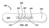
先細部又は漏斗を定める付属デバイスの例が図2Aに示されている。図示のように、付属デバイス200は、2つの周囲開口204のみと、デバイス200の近位面210で可視である凹部分又は漏斗208の底に位置決めされた1つの中心開口206とを定める本体202を含む。幅狭スリット212は、各周囲開口204を中心開口206に接続する。An example of an attachment device defining a tapered portion or funnel is shown in FIG. 2A. As shown, the
漏斗208は、細長介入デバイスを受け入れて周囲開口204及び/又は中心開口206の一方に案内することによって付属デバイス200を通る細長介入デバイスの挿入を容易にすることができる。一部の実施形態では、介入デバイスは、最初に中心開口206を通して挿入され、その後に、スリット212のうちの1つを通して周囲開口204に横方向に移動することができる。この特定の例に示すように、中心開口206は、周囲開口204のいずれよりも大きい直径を有することができ、それによって中心開口206は、細長介入デバイスの遠位端でターゲットにしやすくなる。細長介入デバイスがスリット212を通して周囲開口204のうちの1つまで横方向に移動された時に、スリット212は、細長介入デバイスのより大きい断面直径の周りで拡張することができる。周囲開口204に到達した後に、デバイスが通過したスリット212は、静止幅に戻り、臨床医によって押圧されない限り、細長介入デバイスがスリット212を再び通って中心開口206に向けて通過することができないようになっており、この押圧は、患者からの細長介入デバイスの取り出し中に及び/又は介入デバイスの遠位端がそのターゲット解剖学的部位に達した時に行うことができる。The
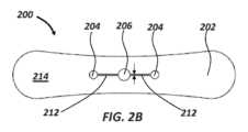
図2Bは、付属デバイス200の遠位面214を示している。中心開口206は、可視であり、スリット212を通して2つの周囲開口204に挟まれる。漏斗208は、この特定の例では、遠位214では不可視であるが、更に別の実施形態では、付属デバイス200の本体202は、開口204、206の周りの両側で凹むことができる。そのような一部の実施形態により、近位面及び遠位面は、同一又は実質的に同一とすることができる。Figure 2B shows the
図2Bで対向する矢印によって説明された各スリット212の幅は、一方の開口から次の開口への介入デバイスの意図しない横方向の摺動を防止するように、及び/又は手術中に介入デバイスの近位端部分を確実に固定するように幅狭とすることができ、その結果、介入デバイスが、臨床医が印加する力がない場合に遠位又は近位に移動することが防止される。実施形態では、スリット212の幅は、約1ミリメートル未満から約2ミリメートル、約3ミリメートル、約4ミリメートル、約5ミリメートル、約6ミリメートル、約7ミリメートル、約8ミリメートル、約9ミリメートル、約10ミリメートル、10ミリメートル以上の範囲とすることができ、又はその間のあらゆる幅とすることができる。各スリット212の幅狭幅は、付属デバイス200を形成するのに使用される材料と組み合わせてガイドワイヤ又は他の小径の介入デバイスの少なくとも一部分を保持及び固定するようにスリット212を構成することができる。図2A及び図2Bに示す各スリット212の幅は、図3に関連して後述するスリットの幅と共に、図1A及び図1Bに示す各スリット114の幅と同一又は類似とすることができる。The width of each
図2A及び図2Bに示す付属デバイス200は、本発明の開示に従って実施することができるサイズ及び/又は形状の多くの変形の一例を示している。図1A及び図1Bに示す付属デバイスと比較して付属デバイス200は、より細長く、より幅狭の幅を定める。開口204、206はまた、付属デバイス100の周囲開口108及び中心開口116とは異なり、付属デバイス200の中心部分付近に含まれ、開口は、異なる数及び種類の細長介入デバイスを受け入れるように異なる実施形態では位置、数、及び/又はサイズが変動する可能性があることを示している。
図3は、スリット308の形態の第1の開口304、第2の開口06、及び幅狭の第3の開口を定める本体302を含む付属デバイス300を示し、これらは、全てデバイスの近位面310で可視である。第1の開口304は、デバイスの第1の端部312内に定めることができ、第2の開口306は、第1の端部の反対側にデバイスの第2の端部314内に定めることができ、スリット308は、デバイスの第1の端部312及び第2の端部314のいずれか又は両方内に定めることができる。3 shows an
第1の開口304又は管腔は、円形断面を有し、上述の付属デバイス100、200によって定められた開口に対して比較的大きい直径を有する。第1の開口304のより大きい直径は、バルーンカテーテル、ステントカテーテル、又はシース部材のような同様に大きい断面直径を有する細長介入デバイスを受け入れるように付属デバイス300を装備する。The
第2の開口306は、ガイド延長カテーテルの近位端に含まれるプッシュ部材又はタブのような別の細長介入デバイスの類似の形状の断面を受け入れるようにほぼ矩形断面を有し、その一例は、図1Aの近位タブ104及びプッシュ部材106によって表される。The
スリット308は、第2の開口306内に異なるサイズの介入デバイスを受け入れるのに使用される締め付け機構として機能し、及び/又は第2の開口への/からの介入デバイスの挿入及び取り出しを容易することができる。例えば、スリット308は、第2の開口306と介入デバイスの間の不完全な嵌合を受け入れるために撓むことができる。スリット308は、図3に示す静止状態に押圧されるので、撓んだ時に介入デバイスの周りに確実に締め付けることができる。スリット308はまた、所与の手術中に第2の開口306によって受け入れられた介入デバイスの横方向の挿入及び取り出し(両面矢印によって図示)を可能にすることができる。そのような横方向の挿入及び取り出しは、介入デバイスへのかつ介入デバイスからの付属デバイス300の迅速かつ容易な取り付け及び切り離しをそれぞれ可能にすることができる。更に別の実施形態は、例えば、通過して延長された細長介入デバイスからの付属デバイス300の容易な切り離し(又は取り付け)を可能にするために、離脱特徴部、ヒンジ部材、バネ部材、スナップ装着部材、又は機械式クランプの形態の類似の締め付け機構又は「迅速解除」機構を含むことができる。類似の締め付け機構は、これに代えて又はこれに加えて、デバイスの第1の端部312に存在して第1の開口304に関連付けることができる。The
図4は、デバイスの近位面408で互いに可視である第1の管腔又は開口404及び第2の管腔又は開口406を定める本体402を含む付属デバイス400を示している。第1の開口404は、付属デバイス400の第1の端部410に定められ、第2の開口406は、付属デバイス400の第2の端部412に定められる。更に示すように、第1の開口404は、複数の端末ノード416を定める十字形管腔414を含む。ノード416の各々は、細長介入デバイスを受け入れることができ、このデバイスは、最初に管腔414のより中心の部分を通して挿入され、その後に、端末ノード416に向けて横方向に摺動させることができる。管腔414の各突起状部分の幅wは、より大きい断面幅を有する介入デバイス及び/又はより多くの介入デバイスを受け入れるように図1から図3に示すスリットの幅よりも大きいとすることができる。一部の例では、不規則な及び/又は大きい断面を有する介入デバイスを十字形管腔414の中心を通って前進させることができる。そのような例により、十字形管腔414の交差部分によって定められた本体402のコーナ418は、介入デバイスの形状及び/又はサイズを受け入れるように撓むことができる。FIG. 4 shows an
本明細書に開示する付属デバイスは、1又は2以上の追加のデバイス、ツール、及び/又は他の材料を有するキットとして提供することができる。例えば、付属デバイスには、止血弁、及び付属デバイスによって受け入れられて保持されるように構成された少なくとも1つの細長医療デバイス、例えば、ガイドワイヤ又はカテーテルを含むことができる。キットに含まれる品目は、特定の医療手術中の一般的な使用又は手術等級に基づいて選択することができる。付属デバイスは、例えば、同じく特定の解剖学的位置に位置することができる特定のタイプの血管病変を治療するに利用されるガイドワイヤ及びカテーテルの対と共にキット内に含めることができる。The accessory devices disclosed herein can be provided as a kit with one or more additional devices, tools, and/or other materials. For example, the accessory device can include a hemostasis valve and at least one elongated medical device, e.g., a guidewire or catheter, configured to be received and retained by the accessory device. The items included in the kit can be selected based on general use during a particular medical procedure or surgical grade. The accessory device can be included in the kit, for example, with a guidewire and catheter pair utilized to treat a particular type of vascular lesion, which can also be located in a particular anatomical location.
本明細書に開示する付属デバイスは、カテーテル及び/又はガイドワイヤの管理方法に対して構成される。例えば、一例示的方法では、カテーテル及び/又はガイドワイヤ管理デバイスは、2又は3以上の血管又は分岐部で同時に治療することができる血管病変を含む様々な医学的異常を治療するのに使用することができる。本方法は、血管の異常及び/又は血管以外の異常に関連する可能性がある。別の用途は、急速交換カテーテルを配備して使用する方法である。そのような用途の1又は2以上により、臨床医は、第1の細長医療デバイスを患者の外側に位置決めされた付属デバイスの第1の管腔又は開口を通して前進させることができる。第1の細長医療デバイスの遠位部分が解剖学的ターゲット、例えば、病変部位に到達する前又は後に、第2の細長医療デバイスを付属デバイスの第2の管腔又は開口を通して延長させることができる。1又は2以上の追加の細長医療デバイスを医療手術の進行にわたってデバイスによって定められた1又は2以上の追加の開口を通して前進させることができる。実施形態は、第1の開口が、受け入れ開口として利用されるように構成され、第2の開口(及び任意的に第3、第4、又は第5の開口のような)が、ターゲット開口として利用されるように構成されるように、最初に細長医療デバイスを第1の開口を通して前進させ、その後に、細長医療デバイスを幅狭スリットを通して第2の開口まで横方向に摺動させる段階を伴う場合がある。1又は2以上の細長医療デバイスは、細長医療デバイスをそのターゲット開口を通して近位又は遠位に摺動させることにより、及び/又は細長医療デバイスの近位部分を開口をデバイスの周囲に接続するスリットを通して横方向に摺動させることにより、付属デバイスから取り出すことができる。方法はまた、細長医療デバイスを付属デバイスによって定められた管腔又は開口を通して遠位及び/又は近位に摺動させ、細長医療デバイスの近位端部分を管腔又は開口に接続された幅狭スリット内に固定する段階を伴う場合がある。そのような例示的方法により、幅狭スリットは、細長医療デバイスを一時的に固定する締め付け機構を提供することができる。The accessory devices disclosed herein are configured for a method of catheter and/or guidewire management. For example, in one exemplary method, the catheter and/or guidewire management device can be used to treat a variety of medical abnormalities, including vascular lesions, which can be treated simultaneously in two or more vessels or branches. The method can relate to vascular and/or non-vascular abnormalities. Another application is a method of deploying and using a rapid exchange catheter. One or more of such applications can allow a clinician to advance a first elongated medical device through a first lumen or opening of the accessory device positioned outside the patient. A second elongated medical device can be extended through a second lumen or opening of the accessory device before or after a distal portion of the first elongated medical device reaches an anatomical target, e.g., a lesion site. One or more additional elongated medical devices can be advanced through one or more additional openings defined by the device over the course of a medical procedure. An embodiment may involve first advancing an elongate medical device through a first opening, such that a first opening is configured to be utilized as a receiving opening, and a second opening (and optionally a third, fourth, or fifth opening, etc.) is configured to be utilized as a target opening, and then sliding the elongate medical device laterally through a narrow slit to a second opening. One or more elongate medical devices may be removed from the attached device by sliding the elongate medical device proximally or distally through its target opening and/or by sliding a proximal portion of the elongate medical device laterally through a slit connecting the opening to the periphery of the device. The method may also involve sliding the elongate medical device distally and/or proximally through a lumen or opening defined by the attached device and securing a proximal end portion of the elongate medical device within a narrow slit connected to the lumen or opening. With such an exemplary method, the narrow slit may provide a fastening mechanism to temporarily secure the elongate medical device.
実施例
上述の詳細説明は、詳細説明の一部を形成する添付図面への参照を含む。詳細説明は、図面を参照して読まれるものとする。図面は、本発明の付属デバイス及び関連の方法を実施することができる特定の実施形態を例示的に示している。これらの実施形態は、本明細書では、「実施例」とも呼ぶ。EXAMPLES The above detailed description includes references to the accompanying drawings, which form a part of the detailed description. The detailed description should be read with reference to the drawings. The drawings show, by way of illustration, specific embodiments in which the present accessory devices and associated methods may be practiced. These embodiments are also referred to herein as "examples."
詳細説明は、例示であって制限的ではないことを意図している。例えば、上述の例(又は1又は2以上の特徴又はその構成要素)は、互いに組み合わせて使用することができる。他の実施形態は、例えば、上述の詳細説明を精査する当業者によるなどで使用することができる。同じく本発明の開示を効率化するために、様々な特徴又は構成要素は、グループ分けされた又はグループ分けすることができる。これは、権利主張しない開示する特徴がいずれかの特許請求の範囲に必須であることを意図しないと解釈しなければならない。むしろ、本発明の主題は、開示する特定の実施形態の全てに満たない特徴に存在することができる。従って、特許請求の範囲の例は、本明細書によって詳細説明に組み込まれ、各例は、独立した実施形態としてそれ自体で成り立つものである。The detailed description is intended to be illustrative and not restrictive. For example, the above examples (or one or more features or components thereof) can be used in combination with each other. Other embodiments can be used, for example, by those of ordinary skill in the art who review the above detailed description. Also, various features or components may be grouped or separated to streamline the disclosure of the invention. This should not be construed as intending that an unclaimed disclosed feature is essential to any claim. Rather, inventive subject matter may reside in less than all features of a particular disclosed embodiment. Thus, the examples of the claims are hereby incorporated into the detailed description, with each example standing on its own as an independent embodiment.
実施例1では、細長医療デバイスを管理するためのデバイスは、近位面及び遠位面を有し、本体を通って延びる少なくとも第1及び第2の開口を含む本体を含むことができる。第1の開口は、第1の細長医療デバイスの近位端部分と係合可能であるように構成することができ、第2の開口は、第2の細長医療デバイスを受け入れるように構成することができる。In Example 1, a device for managing an elongate medical device can include a body having a proximal surface and a distal surface and including at least first and second openings extending through the body. The first opening can be configured to be engageable with a proximal end portion of the first elongate medical device, and the second opening can be configured to receive the second elongate medical device.
実施例2では、実施例1のデバイスは、任意的に、本体が第1の細長医療デバイスの近位端部分に沿って摺動可能であるように構成することができる。In Example 2, the device of Example 1 can optionally be configured such that the body is slidable along the proximal end portion of the first elongate medical device.
実施例3では、実施例1又は実施例2のいずれか1つのデバイスは、任意的であり、本体の近位面が第1の開口、第2の開口、又はその両方の中に至る漏斗を含むように構成することができる。In Example 3, the device of any one of Examples 1 or 2 can be optionally configured such that the proximal surface of the body includes a funnel leading into the first opening, the second opening, or both.
実施例4では、実施例1から実施例3のいずれか1つ又はいずれかの組合せのデバイスは、任意的に、本体が止血弁の近位側に組み込まれるか又は取り付けられるように構成することができる。In Example 4, the device of any one or any combination of Examples 1 to 3 can optionally be configured such that the body is incorporated or attached proximal to the hemostasis valve.
実施例5では、実施例1から実施例4のいずれか1つ又はいずれかの組合せのデバイスは、任意的に、本体が第1の細長医療デバイスの近位端部分に締め付け可能であるように構成することができる。In Example 5, the device of any one or any combination of Examples 1 to 4 can optionally be configured such that the body is clampable to a proximal end portion of the first elongate medical device.
実施例6では、実施例1から実施例5のいずれか1つ又はいずれかの組合せのデバイスは、任意的に、第2の開口が本体を通るスリットを含み、スリットがガイドワイヤ又は他の小径の細長医療デバイスを固定するように構成されるように構成することができる。In Example 6, the device of any one or any combination of Examples 1 to 5 can optionally be configured such that the second opening includes a slit through the body, the slit configured to secure a guidewire or other small diameter elongated medical device.
実施例7では、実施例1から実施例6のいずれか1つ又はいずれかの組合せのデバイスは、任意的に、第1及び第2の開口の一方又は両方が第1又は第2の細長医療デバイスからデバイスを取り付ける及び切り離すように構成された締め付け機構を含むように構成することができる。In Example 7, the device of any one or any combination of Examples 1 to 6 can optionally be configured such that one or both of the first and second openings include a fastening mechanism configured to attach and detach the device from the first or second elongate medical device.
実施例8では、実施例7のデバイスは、任意的に、締め付け機構が第1及び第2の開口の一方又は両方から本体の周囲に延びるスリットを含むように構成することができる。In Example 8, the device of Example 7 can be optionally configured such that the fastening mechanism includes a slit extending from one or both of the first and second openings around the body.
実施例9では、実施例1から実施例8のいずれか1つ又はいずれかの組合せのデバイスは、任意的に、本体が近位面から遠位面まで測定した時に約0.5から約3センチメートルの範囲の厚みを有するように構成することができる。In Example 9, the device of any one or any combination of Examples 1 to 8 can optionally be configured such that the body has a thickness in the range of about 0.5 to about 3 centimeters as measured from the proximal surface to the distal surface.
実施例10では、実施例1から実施例9のいずれか1つ又はいずれかの組合せのデバイスは、任意的に、第1又は第2の開口内に位置決めされた変形可能な膜を更に含むように構成することができる。In Example 10, the device of any one or any combination of Examples 1 to 9 can be optionally further configured to include a deformable membrane positioned within the first or second opening.
実施例11では、実施例1から実施例10のいずれか1つ又はいずれかの組合せのデバイスは、任意的に、本体が手動で変形可能であるように構成することができる。In Example 11, the device of any one or any combination of Examples 1 to 10 may optionally be configured such that the body is manually deformable.
実施例12では、実施例1から実施例11のいずれか1つ又はいずれかの組合せのデバイスは、任意的に、本体が約20から約60のショアAデュロメーターを有するように構成することができる。In Example 12, the device of any one or any combination of Examples 1 to 11 can optionally be configured such that the body has a Shore A durometer of about 20 to about 60.
実施例13では、実施例1から実施例12のいずれか1つ又はいずれかの組合せのデバイスは、任意的に、第1の開口と第2の開口の間を延びる幅狭スリットを更に含むように構成することができる。In Example 13, the device of any one or any combination of Examples 1 to 12 can be optionally further configured to include a narrow slit extending between the first opening and the second opening.
実施例14では、実施例1から実施例13のいずれか1つ又はいずれかの組合せのデバイスは、任意的に、第1の開口と第2の開口の間に位置決めされた第3の開口を含むように構成することができる。In Example 14, the device of any one or any combination of Examples 1 to 13 can be optionally configured to include a third opening positioned between the first opening and the second opening.
実施例15では、実施例14のデバイスは、任意的に、第1の開口と第3の開口の間を延びる第1の幅狭スリット、及び第2の開口と第3の開口の間を延びる第2の幅狭スリットを更に含むように構成することができる。In Example 15, the device of Example 14 can be optionally further configured to include a first narrow slit extending between the first opening and the third opening, and a second narrow slit extending between the second opening and the third opening.
実施例16では、実施例14又は実施例15のいずれか1つのデバイスは、任意的に、第3の開口が第1及び第2の開口よりも大きい直径を有するように構成することができる。In Example 16, the device of either Example 14 or Example 15 can optionally be configured such that the third opening has a larger diameter than the first and second openings.
実施例17では、患者に行われる医療手術中に細長医療デバイスを固定する方法は、第1の細長医療デバイスを付属デバイスの本体を通って延びる第1の開口を通して前進させる段階を伴うことができ、付属デバイスは、近位及び遠位の面を有し、患者の外部に位置決めされる。本方法は、第1の細長医療デバイスの近位部分を第1の開口内に固定する段階と、第2の細長医療デバイスを付属デバイスの本体を通って延びる第2の開口を通して前進させる段階と、第2の細長医療デバイスの近位部分を第2の開口内に固定する段階とを伴うことができる。In Example 17, a method of securing an elongate medical device during a medical procedure performed on a patient can involve advancing a first elongate medical device through a first opening extending through a body of an attachment device, the attachment device having a proximal and a distal surface and positioned external to the patient. The method can involve securing a proximal portion of the first elongate medical device within the first opening, advancing a second elongate medical device through a second opening extending through a body of the attachment device, and securing a proximal portion of the second elongate medical device within the second opening.
実施例18では、実施例17の方法は、任意的に、第1の細長デバイスの近位部分を第1の開口内に固定する段階が、付属デバイスの本体が第1の細長医療デバイスの近位部分を把持することを可能にする段階を含むように実施することができる。In Example 18, the method of Example 17 can optionally be performed such that the step of securing the proximal portion of the first elongate device within the first opening includes a step of enabling the body of the attachment device to grasp the proximal portion of the first elongate medical device.
実施例19では、実施例17又は実施例18のいずれか1つの方法は、任意的に、第1の開口を付属デバイスの周囲に接続するスリットを通して近位部分を横方向に摺動させることにより、第1の細長医療デバイスの近位部分を第1の開口から取り出す段階を更に伴うことができる。In Example 19, the method of any one of Examples 17 or 18 can optionally further include removing the proximal portion of the first elongate medical device from the first opening by sliding the proximal portion laterally through a slit connecting the first opening to the periphery of the accessory device.
実施例20では、実施例17から実施例19のいずれか1つ又はいずれかの組合せの方法は、任意的に、第2の開口が第2の細長医療デバイスの近位部分を摩擦固定するように構成された幅狭スリットを含むように実施することができる。In Example 20, the method of any one or any combination of Examples 17 to 19 can be optionally performed such that the second opening includes a narrow slit configured to frictionally secure a proximal portion of the second elongate medical device.
実施例21では、実施例17から実施例20のいずれか1つ又はいずれかの組合せの方法は、任意的に、付属デバイスの本体が第1の開口、第2の開口、又はその両方の中に至る漏斗を更に含むように実施することができる。In Example 21, the method of any one or any combination of Examples 17 to 20 can be optionally performed such that the body of the attachment device further includes a funnel leading into the first opening, the second opening, or both.
結びの注記
ある一定の用語は、本特許文献で特定の特徴又は構成要素を指すのに使用される。当業者は認識するように、人が変われば異なる名称によって同じ特徴又は構成要素を指す場合がある。本特許文献は、名称は異なるが機能は異ならない構成要素又は機能を区別することを意図していない。Concluding Notes : Certain terms are used in this patent document to refer to particular features or components. As one of ordinary skill in the art will recognize, different people may refer to the same feature or component by different names. This patent document does not intend to distinguish between components or functions that differ in name but not function.
以下に定める用語に関して、本特許文献に異なる定義が与えられない限り、ある一定の定義が適用されるものとする。用語「a」、「an」、及び「the」は、「少なくとも1つ」又は「1又は2以上」の他の事例又は用法とは無関係に1又は2以上を含むように使用される。用語「or」は、「A又はB」が「A、しかしBではない」,「B、しかしAではない」、及び「A及びB」を含むように非限定的orを意味する。全ての数値は、明示的に示されたか否かに関わらず、「約」という用語によって修正されることが仮定される。用語「約」は、一般的に、当業者が言及された値と同等と見なす(例えば、同じ関数又は結果を有する)数値の範囲を意味する。多くの事例では、「約」という用語は、最も近い有効数字に丸められた数字を含むことができる。端点による数値範囲の記載は、その範囲の全ての数値及びその範囲を境界とする部分的範囲(例えば、1から4は、1、1.5、1.75、2、2.3、2.6、2.9のような及び1から1.5、1から2、1から3、2から3.5、2から4、3から4のような)を含む。「患者」及び「被験者」という用語は、ヒト又は獣医用途に対するような哺乳類を含むことを意図している。用語「遠位」及び「近位」は、治療する臨床医に対する相対的な位置又は方向を指すのに使用される。「遠位」及び「遠位に」は、治療する臨床医から遠い位置又は遠ざかる方向の位置を指す。「近位」及び「近位に」は、治療する臨床医の近い又は臨床医に向う方向にある位置を指す。For the terms defined below, certain definitions shall apply unless a different definition is given in this patent document. The terms "a," "an," and "the" are used to include one or more, regardless of other instances or usages of "at least one" or "one or more than one." The term "or" means an open-ended or, such that "A or B" includes "A, but not B," "B, but not A," and "A and B." All numerical values are assumed to be modified by the term "about," whether or not expressly stated. The term "about" generally refers to a range of numerical values that one of ordinary skill in the art would consider equivalent to the stated value (e.g., having the same function or result). In many instances, the term "about" may include numbers rounded to the nearest significant figure. The recitation of numerical ranges by endpoints includes all values within that range and subranges bounding that range (e.g., 1 to 4 includes 1, 1.5, 1.75, 2, 2.3, 2.6, 2.9, and the like, 1 to 1.5, 1 to 2, 1 to 3, 2 to 3.5, 2 to 4, 3 to 4, and the like). The terms "patient" and "subject" are intended to include mammals, such as humans or for veterinary use. The terms "distal" and "proximal" are used to refer to a location or direction relative to a treating clinician. "Distal" and "distally" refer to a location that is further away or away from a treating clinician. "Proximal" and "proximally" refer to a location that is closer to or in a direction toward a treating clinician.
本発明の範囲は、特許請求の範囲を参照し、そのような特許請求の範囲は、権利を有する均等物の全範囲と共に決定する必要がある。特許請求の範囲では、用語「including」及び「in which」は、それぞれの用語「comprising」及び「wherein」の平易な英語での均等物として使用される。同じく、特許請求の範囲では、用語「含む」及び「備える」は、無制限であり、すなわち、特許請求の範囲の当該用語の後に説明された特徴又は構成要素に加えて、特徴又は構成要素を含むデバイス、キット、方法が依然としてその特許請求の範囲に該当すると見なされる。更に、以下の特許請求の範囲では、用語「第1」、「第2」、及び「第3」などは、単にラベルとして使用され、それらの対象物に対する数値的な要件を課すことを意図しない。The scope of the invention should be determined with reference to the claims, which should be taken together with the full scope of equivalents to which such claims are entitled. In the claims, the terms "including" and "in which" are used as the plain English equivalents of the respective terms "comprising" and "wherein." Also, in the claims, the terms "including" and "having" are open-ended, i.e., devices, kits, and methods that include features or components in addition to those described after that term in the claim are still considered to fall within the scope of that claim. Moreover, in the following claims, the terms "first," "second," and "third," etc. are used merely as labels and are not intended to impose numerical requirements on their objects.
「要約」は、読者が技術開示の内容を迅速に把握することを可能にするために提供している。特許請求の範囲又は意味を解釈する又は制限するのに使用されないことを理解した上で提示している。
本発明のその他の実施態様を以下に記載する。
〔実施形態1〕
細長医療デバイスを管理するためのデバイスであって、
近位及び遠位面を有する本体であって、該本体を通って延びる少なくとも第1の及び第2の開口を含む前記本体、
を備え、
前記第1の開口は、第1の細長医療デバイスの近位端部分と係合可能であるように構成され、
前記第2の開口は、第2の細長医療デバイスを受け入れるように構成される、ことを特徴とするデバイス。
〔実施形態2〕
前記本体は、前記第1の細長医療デバイスの前記近位端部分に沿って摺動可能である、実施形態1に記載のデバイス。
〔実施形態3〕
前記本体の前記近位面は、前記第1の開口、前記第2の開口、又はその両方の中に至る漏斗を含む、実施形態1又は実施形態2に記載のデバイス。
〔実施形態4〕
前記本体は、止血弁の近位側の中に組み込まれるか又はそれに取り付けられる、実施形態1から実施形態3のいずれか1項に記載のデバイス。
〔実施形態5〕
前記本体は、前記第1の細長医療デバイスの前記近位端部分に締め付け可能である、実施形態1から実施形態4のいずれか1項に記載のデバイス。
〔実施形態6〕
前記第2の開口は、前記本体を通るスリットを備え、該スリットは、ガイドワイヤ又は他の小径の細長医療デバイスを固定するように構成される、実施形態1から実施形態5のいずれか1項に記載のデバイス。
〔実施形態7〕
前記第1及び第2の開口の一方又は両方が、前記第1又は第2の細長医療デバイスに対してデバイスを取り付ける及び切り離すように構成された締め付け機構を含む、実施形態1から実施形態6のいずれか1項に記載のデバイス。
〔実施形態8〕
前記締め付け機構は、前記第1及び第2の開口の一方又は両方から前記本体の周囲まで延びるスリットを備える、実施形態7に記載のデバイス。
〔実施形態9〕
前記本体は、前記近位面から前記遠位面まで測定した時に包含的に約0.5から約3センチメートルまでの範囲の厚みを有する、実施形態1から実施形態8のいずれか1項に記載のデバイス。
〔実施形態10〕
前記第1又は第2の開口内に位置決めされた変形可能な膜を更に備える、実施形態1から実施形態9のいずれか1項に記載のデバイス。
〔実施形態11〕
前記本体は、手動で変形可能である、実施形態1から実施形態10のいずれか1項に記載のデバイス。
〔実施形態12〕
前記本体は、包含的に約20と約60の間のショアAデュロメーターを有する、実施形態1から実施形態11のいずれか1項に記載のデバイス。
〔実施形態13〕
前記第1の開口と前記第2の開口の間を延びる幅狭スリットを更に備える、実施形態1から実施形態12のいずれか1項に記載のデバイス。
〔実施形態14〕
前記第1の開口と前記第2の開口の間に位置決めされた第3の開口を更に備える、実施形態1から実施形態13のいずれか1項に記載のデバイス。
〔実施形態15〕
前記第1の開口と前記第3の開口の間を延びる第1の幅狭スリット及び前記第2の開口と該第3の開口の間を延びる第2の幅狭スリットを更に備える、実施形態14に記載のデバイス。
〔実施形態16〕
前記第3の開口は、前記第1及び第2の開口よりも大きい直径を有する、実施形態14又は実施形態15に記載のデバイス。
〔実施形態17〕
患者に対して行われる医療手術中に細長医療デバイスを固定する方法であって、
付属デバイスの本体を通って延びる第1の開口を通して第1の細長医療デバイスを前進させる段階であって、該付属デバイスが、近位及び遠位面を有し、かつ前記患者に対して外部に位置決めされる前記前進させる段階と、
前記第1の細長医療デバイスの近位部分を前記第1の開口内に固定する段階と、
前記付属デバイスの前記本体を通って延びる第2の開口を通して第2の細長医療デバイスを前進させる段階と、
前記第2の細長医療デバイスの近位部分を前記第2の開口内に固定する段階と、
を備える、ことを特徴とする方法。
〔実施形態18〕
前記第1の細長デバイスの前記近位部分を前記第1の開口内に固定する段階は、前記付属デバイスの前記本体が該第1の細長医療デバイスの該近位部分を把持することを可能にする段階を備える、実施形態17に記載の方法。
〔実施形態19〕
前記第1の細長医療デバイスの前記近位部分を前記第1の開口から該第1の開口を前記付属デバイスの周囲に接続するスリットを通して該近位部分を横方向に摺動させることによって取り出す段階を更に備える、実施形態17又は実施形態18に記載の方法。
〔実施形態20〕
前記第2の開口は、前記第2の細長医療デバイスの前記近位部分を摩擦固定するように構成された幅狭スリットを備える、実施形態17から実施形態19のいずれか1項に記載の方法。
〔実施形態21〕
前記付属デバイスの前記本体は、前記第1の開口、前記第2の開口、又はその両方の中に至る漏斗を更に備える、実施形態17から実施形態20のいずれか1項に記載の方法。 The Abstract is provided to enable the reader to quickly grasp the contents of the technical disclosure and is presented with the understanding that it will not be used to interpret or limit the scope or meaning of the claims.
Other embodiments of the invention are described below.
[Embodiment 1]
1. A device for managing an elongated medical device, comprising:
a body having proximal and distal faces, the body including at least first and second openings extending therethrough;
Equipped with
the first opening is configured to be engageable with a proximal end portion of a first elongate medical device;
The second opening is configured to receive a second elongate medical device.
[Embodiment 2]
2. The device of embodiment 1, wherein the body is slidable along the proximal end portion of the first elongate medical device.
[Embodiment 3]
The device of embodiment 1 or embodiment 2, wherein the proximal surface of the body includes a funnel leading into the first opening, the second opening, or both.
[Embodiment 4]
A device according to any one of the preceding embodiments, wherein the body is integrated into or attached to the proximal side of the hemostasis valve.
[Embodiment 5]
The device of any one of the preceding claims, wherein the body is fastenable to the proximal end portion of the first elongate medical device.
[Embodiment 6]
The device of any one of claims 1 to 5, wherein the second opening comprises a slit through the body configured to secure a guidewire or other small diameter elongated medical device.
[Embodiment 7]
The device of any one of embodiments 1 to 6, wherein one or both of the first and second openings include a fastening mechanism configured to attach and detach the device to the first or second elongate medical device.
[Embodiment 8]
8. The device of embodiment 7, wherein the fastening mechanism comprises a slit extending from one or both of the first and second openings to a periphery of the body.
[Embodiment 9]
The device of any one of the preceding claims, wherein the body has a thickness in the range of about 0.5 to about 3 centimeters, inclusive, as measured from the proximal surface to the distal surface.
[Embodiment 10]
10. The device of any one of the preceding claims, further comprising a deformable membrane positioned within the first or second opening.
[Embodiment 11]
The device of any one of the preceding claims, wherein the body is manually deformable.
[Embodiment 12]
12. The device of any one of the preceding claims, wherein the body has a Shore A durometer of between about 20 and about 60, inclusive.
[Embodiment 13]
13. The device of any one of the preceding claims, further comprising a narrow slit extending between the first opening and the second opening.
[Embodiment 14]
14. The device of any one of the preceding claims, further comprising a third opening positioned between the first opening and the second opening.
[Embodiment 15]
15. The device of embodiment 14, further comprising a first narrow slit extending between the first opening and the third opening and a second narrow slit extending between the second opening and the third opening.
[Embodiment 16]
16. The device of embodiment 14 or embodiment 15, wherein the third opening has a larger diameter than the first and second openings.
[Embodiment 17]
1. A method of securing an elongated medical device during a medical procedure performed on a patient, comprising:
advancing a first elongate medical device through a first opening extending through a body of an attachment device, the attachment device having proximal and distal faces and positioned externally to the patient;
securing a proximal portion of the first elongate medical device within the first opening;
advancing a second elongate medical device through a second opening extending through the body of the attachment device;
securing a proximal portion of the second elongate medical device within the second opening;
13. A method comprising:
[Embodiment 18]
18. The method of embodiment 17, wherein fixing the proximal portion of the first elongate device within the first opening comprises enabling the body of the accessory device to grasp the proximal portion of the first elongate medical device.
[Embodiment 19]
The method of embodiment 17 or embodiment 18, further comprising removing the proximal portion of the first elongate medical device by sliding the proximal portion laterally from the first opening through a slit connecting the first opening to the circumference of the accessory device.
[Embodiment 20]
The method of any one of embodiments 17 to 19, wherein the second opening comprises a narrow slit configured to frictionally secure the proximal portion of the second elongate medical device.
[Embodiment 21]
21. The method of any one of embodiments 17 to 20, wherein the body of the accessory device further comprises a funnel leading into the first opening, the second opening, or both.
100 付属デバイス
102 ガイド延長カテーテルデバイス
104 近位タブ
108 周囲管腔又は開口
110 付属デバイスの本体100
Claims (8)
Translated fromJapanese近位面と、前記近位面と反対側の遠位面と、前記近位面と前記遠位面との間に延びる横面と、を有する本体であって、前記横面が0.5センチメートルから3センチメートルの範囲の本体の厚みを定める本体と、
前記本体の連続した外周内の各々の位置において、前記近位面から前記本体を通って前記遠位面へ各々延びる第1の開口及び第2の開口であって、前記第1の開口は、第1の細長医療デバイスの近位端部分と係合可能であるように構成され、前記第2の開口は、第2の細長医療デバイスを受け入れるように構成される第1の開口及び第2の開口と、
前記近位面から前記本体を通って前記遠位面へ延びるスリットであって、前記第1の開口で終端する第1の端部及び前記第2の開口で終端する第2の端部を有し、前記本体の連続した外周内に完全に位置するスリットと、
を備えることを特徴とするデバイス。 1. A device for managing an elongated medical device, comprising:
a body having a proximal surface, a distal surface opposite the proximal surface, and a lateral surface extending between the proximal surface and the distal surface,the lateral surface defining a thickness of the body in the range of 0.5 centimeters to 3 centimeters;
a first opening and a second opening each extending from the proximal surface through the body to the distal surface at respective locations within a continuous circumference of the body, the first opening configured to be engageable with a proximal end portion of a first elongate medical deviceand the second opening configured to receive a second elongate medical device;
a slit extending from the proximal surface through the body to the distal surface, the slit having a first end terminating in the first opening and a second end terminating in the second opening, the slit lying entirely within a continuous circumference of the body;
A devicecomprising :
Applications Claiming Priority (3)
| Application Number | Priority Date | Filing Date | Title |
|---|---|---|---|
| US202063003404P | 2020-04-01 | 2020-04-01 | |
| US63/003,404 | 2020-04-01 | ||
| PCT/US2021/014392WO2021201955A1 (en) | 2020-04-01 | 2021-01-21 | Guidewire and catheter management device |
Publications (2)
| Publication Number | Publication Date |
|---|---|
| JP2023519731A JP2023519731A (en) | 2023-05-12 |
| JP7539602B2true JP7539602B2 (en) | 2024-08-26 |
Family
ID=74626203
Family Applications (1)
| Application Number | Title | Priority Date | Filing Date |
|---|---|---|---|
| JP2022559731AActiveJP7539602B2 (en) | 2020-04-01 | 2021-01-21 | Guidewires and Catheter Management Devices |
Country Status (6)
| Country | Link |
|---|---|
| US (1) | US11752307B2 (en) |
| EP (1) | EP4126170A1 (en) |
| JP (1) | JP7539602B2 (en) |
| AU (1) | AU2021248906B2 (en) |
| CA (1) | CA3176891A1 (en) |
| WO (1) | WO2021201955A1 (en) |
Families Citing this family (11)
| Publication number | Priority date | Publication date | Assignee | Title |
|---|---|---|---|---|
| US9237925B2 (en) | 2011-04-22 | 2016-01-19 | Ablative Solutions, Inc. | Expandable catheter system for peri-ostial injection and muscle and nerve fiber ablation |
| US10736656B2 (en) | 2012-10-29 | 2020-08-11 | Ablative Solutions | Method for painless renal denervation using a peri-vascular tissue ablation catheter with support structures |
| US9526827B2 (en) | 2012-10-29 | 2016-12-27 | Ablative Solutions, Inc. | Peri-vascular tissue ablation catheter with support structures |
| US10881458B2 (en) | 2012-10-29 | 2021-01-05 | Ablative Solutions, Inc. | Peri-vascular tissue ablation catheters |
| US9301795B2 (en) | 2012-10-29 | 2016-04-05 | Ablative Solutions, Inc. | Transvascular catheter for extravascular delivery |
| US9949652B2 (en) | 2013-10-25 | 2018-04-24 | Ablative Solutions, Inc. | Apparatus for effective ablation and nerve sensing associated with denervation |
| US10517666B2 (en) | 2013-10-25 | 2019-12-31 | Ablative Solutions, Inc. | Apparatus for effective ablation and nerve sensing associated with denervation |
| US9931046B2 (en) | 2013-10-25 | 2018-04-03 | Ablative Solutions, Inc. | Intravascular catheter with peri-vascular nerve activity sensors |
| US10849685B2 (en) | 2018-07-18 | 2020-12-01 | Ablative Solutions, Inc. | Peri-vascular tissue access catheter with locking handle |
| US20230355292A1 (en)* | 2022-05-06 | 2023-11-09 | Ablative Solutions, Inc. | Radial compatible catheter for peri-vascular fluid injection |
| WO2024176619A1 (en)* | 2023-02-22 | 2024-08-29 | テルモ株式会社 | Hemostasis valve |
Citations (5)
| Publication number | Priority date | Publication date | Assignee | Title |
|---|---|---|---|---|
| JP2002515305A (en) | 1998-05-18 | 2002-05-28 | ボストン サイエンティフィック リミテッド | Apparatus and method for securing guidewire and catheter |
| US20100094227A1 (en) | 2008-10-13 | 2010-04-15 | Applied Medical Resources Corporation | Single port access system |
| US20120271236A1 (en) | 2011-04-19 | 2012-10-25 | Medtronic Vascular, Inc. | Sheath Introducer System with Exchangeable Hemostatic Valves |
| JP2016087147A (en) | 2014-11-06 | 2016-05-23 | ニプロ株式会社 | Support catheter |
| US10321933B1 (en) | 2014-09-24 | 2019-06-18 | MarVenRay, LLC | Apparatus and methods for vascular access |
Family Cites Families (19)
| Publication number | Priority date | Publication date | Assignee | Title |
|---|---|---|---|---|
| JPS5216630Y2 (en)* | 1971-07-22 | 1977-04-14 | ||
| JPH06233824A (en)* | 1993-02-08 | 1994-08-23 | Nippon Zeon Co Ltd | Catheter tube set |
| US5451212A (en) | 1994-01-21 | 1995-09-19 | Corpak, Inc. | Bumper retention device |
| US5643217A (en) | 1995-01-05 | 1997-07-01 | Dobkin; William R. | Surgical attachment device |
| US5795335A (en) | 1997-02-26 | 1998-08-18 | Zinreich; Eva S. | Intravenous tube restraint and cover device |
| US5902275A (en) | 1997-04-21 | 1999-05-11 | Dobkin; William R. | Surgical attachment device for use with angioplasty devices and the like |
| US6551283B1 (en)* | 2000-01-25 | 2003-04-22 | St. Jude Medical, Daig Division | Hemostasis valve |
| EP1654026B1 (en)* | 2003-07-31 | 2008-10-29 | Wilson-Cook Medical Inc. | Wire guide holder |
| US7229051B2 (en) | 2005-02-14 | 2007-06-12 | Mailhot Jr Robert | Support device for guidewires and catheters and method of use thereof |
| WO2008051898A2 (en) | 2006-10-22 | 2008-05-02 | Via Biomedical, Inc. | Devices and methods for unwrapping or preventing the wrapping of elongated medical devices |
| US9456877B2 (en)* | 2006-12-01 | 2016-10-04 | Boston Scientific Scimed, Inc. | Direct drive instruments and methods of use |
| NO20081172L (en) | 2008-03-05 | 2009-09-07 | Inora As | Device for attaching hoses and wires |
| US8523824B2 (en) | 2008-07-08 | 2013-09-03 | Vascular Solutions, Inc. | Guidewire and catheter management device |
| US8366638B2 (en)* | 2008-07-08 | 2013-02-05 | Teirstein Paul S | Guide wire loading method and apparatus with towel attachment mechanism and retaining member |
| US8728011B2 (en) | 2011-07-22 | 2014-05-20 | Michael D. Khoury | Multi wire sheath |
| US9931488B2 (en)* | 2013-12-09 | 2018-04-03 | Epgear, Llc | Holding devices for elongated instruments |
| US9925285B1 (en)* | 2017-06-21 | 2018-03-27 | Inikoa Medical, Inc. | Disinfecting methods and apparatus |
| AU2019295617B2 (en)* | 2018-06-25 | 2025-02-06 | Novonate, Inc. | Systems and methods for securing catheters |
| US20210327612A1 (en)* | 2020-04-20 | 2021-10-21 | Susan K. Park | System, method, kit and apparatus for organizing cables |
- 2021
- 2021-01-21EPEP21705778.5Apatent/EP4126170A1/enactivePending
- 2021-01-21WOPCT/US2021/014392patent/WO2021201955A1/ennot_activeCeased
- 2021-01-21JPJP2022559731Apatent/JP7539602B2/enactiveActive
- 2021-01-21AUAU2021248906Apatent/AU2021248906B2/enactiveActive
- 2021-01-21CACA3176891Apatent/CA3176891A1/enactivePending
- 2021-01-21USUS17/154,535patent/US11752307B2/enactiveActive
Patent Citations (5)
| Publication number | Priority date | Publication date | Assignee | Title |
|---|---|---|---|---|
| JP2002515305A (en) | 1998-05-18 | 2002-05-28 | ボストン サイエンティフィック リミテッド | Apparatus and method for securing guidewire and catheter |
| US20100094227A1 (en) | 2008-10-13 | 2010-04-15 | Applied Medical Resources Corporation | Single port access system |
| US20120271236A1 (en) | 2011-04-19 | 2012-10-25 | Medtronic Vascular, Inc. | Sheath Introducer System with Exchangeable Hemostatic Valves |
| US10321933B1 (en) | 2014-09-24 | 2019-06-18 | MarVenRay, LLC | Apparatus and methods for vascular access |
| JP2016087147A (en) | 2014-11-06 | 2016-05-23 | ニプロ株式会社 | Support catheter |
Also Published As
| Publication number | Publication date |
|---|---|
| EP4126170A1 (en) | 2023-02-08 |
| US11752307B2 (en) | 2023-09-12 |
| AU2021248906B2 (en) | 2023-11-02 |
| WO2021201955A1 (en) | 2021-10-07 |
| JP2023519731A (en) | 2023-05-12 |
| AU2021248906A1 (en) | 2022-10-13 |
| CA3176891A1 (en) | 2021-10-07 |
| US20210308430A1 (en) | 2021-10-07 |
Similar Documents
| Publication | Publication Date | Title |
|---|---|---|
| JP7539602B2 (en) | Guidewires and Catheter Management Devices | |
| CN215916117U (en) | Quick-insertion central catheter assembly | |
| JP5717884B2 (en) | Catheter guide wire introduction device | |
| US20080243165A1 (en) | Introducer assembly and method therefor | |
| JP4979337B2 (en) | Catheter fixation device | |
| US11944767B2 (en) | Wire lock assembly | |
| JP2011527609A (en) | Guidewire / catheter management device | |
| US20190307990A1 (en) | Guidewire securement device | |
| US20040260205A1 (en) | Guidewire exit tool | |
| US20230270990A1 (en) | Guidewire and catheter management device and related methods | |
| CN116265035A (en) | Catheter placement system, method of loading guidewire into lumen of catheter and method of placing catheter | |
| US20220218952A1 (en) | Device and system for locating guidewire | |
| US20230099710A1 (en) | Vascular access reversing device and methods of use thereof |
Legal Events
| Date | Code | Title | Description |
|---|---|---|---|
| A521 | Request for written amendment filed | Free format text:JAPANESE INTERMEDIATE CODE: A523 Effective date:20221013 | |
| A621 | Written request for application examination | Free format text:JAPANESE INTERMEDIATE CODE: A621 Effective date:20221013 | |
| A977 | Report on retrieval | Free format text:JAPANESE INTERMEDIATE CODE: A971007 Effective date:20230911 | |
| A131 | Notification of reasons for refusal | Free format text:JAPANESE INTERMEDIATE CODE: A131 Effective date:20230919 | |
| A521 | Request for written amendment filed | Free format text:JAPANESE INTERMEDIATE CODE: A523 Effective date:20231219 | |
| TRDD | Decision of grant or rejection written | ||
| A01 | Written decision to grant a patent or to grant a registration (utility model) | Free format text:JAPANESE INTERMEDIATE CODE: A01 Effective date:20240104 | |
| A711 | Notification of change in applicant | Free format text:JAPANESE INTERMEDIATE CODE: A712 Effective date:20240205 Free format text:JAPANESE INTERMEDIATE CODE: A711 Effective date:20240205 | |
| A61 | First payment of annual fees (during grant procedure) | Free format text:JAPANESE INTERMEDIATE CODE: A61 Effective date:20240205 | |
| R150 | Certificate of patent or registration of utility model | Ref document number:7539602 Country of ref document:JP Free format text:JAPANESE INTERMEDIATE CODE: R150 |