JP7539401B2 - CVD reactor susceptor structure - Google Patents
CVD reactor susceptor structureDownload PDFInfo
- Publication number
- JP7539401B2 JP7539401B2JP2021553376AJP2021553376AJP7539401B2JP 7539401 B2JP7539401 B2JP 7539401B2JP 2021553376 AJP2021553376 AJP 2021553376AJP 2021553376 AJP2021553376 AJP 2021553376AJP 7539401 B2JP7539401 B2JP 7539401B2
- Authority
- JP
- Japan
- Prior art keywords
- covering plate
- susceptor
- main surface
- covering
- lowermost
- Prior art date
- Legal status (The legal status is an assumption and is not a legal conclusion. Google has not performed a legal analysis and makes no representation as to the accuracy of the status listed.)
- Active
Links
- 239000000758substrateSubstances0.000claimsdescription39
- 238000000576coating methodMethods0.000claimsdescription18
- 239000011248coating agentSubstances0.000claimsdescription16
- 238000000034methodMethods0.000claimsdescription15
- HBMJWWWQQXIZIP-UHFFFAOYSA-Nsilicon carbideChemical compound[Si+]#[C-]HBMJWWWQQXIZIP-UHFFFAOYSA-N0.000claimsdescription13
- 229910010271silicon carbideInorganic materials0.000claimsdescription13
- 125000006850spacer groupChemical group0.000claimsdescription8
- OKTJSMMVPCPJKN-UHFFFAOYSA-NCarbonChemical compound[C]OKTJSMMVPCPJKN-UHFFFAOYSA-N0.000claimsdescription6
- 229910002804graphiteInorganic materials0.000claimsdescription6
- 239000010439graphiteSubstances0.000claimsdescription6
- 239000000463materialSubstances0.000claimsdescription6
- 238000003780insertionMethods0.000claimsdescription5
- 230000037431insertionEffects0.000claimsdescription5
- MCMNRKCIXSYSNV-UHFFFAOYSA-NZirconium dioxideChemical compoundO=[Zr]=OMCMNRKCIXSYSNV-UHFFFAOYSA-N0.000claimsdescription4
- 238000010438heat treatmentMethods0.000claimsdescription4
- 239000010453quartzSubstances0.000claimsdescription3
- VYPSYNLAJGMNEJ-UHFFFAOYSA-Nsilicon dioxideInorganic materialsO=[Si]=OVYPSYNLAJGMNEJ-UHFFFAOYSA-N0.000claimsdescription3
- PNEYBMLMFCGWSK-UHFFFAOYSA-Naluminium oxideInorganic materials[O-2].[O-2].[O-2].[Al+3].[Al+3]PNEYBMLMFCGWSK-UHFFFAOYSA-N0.000claimsdescription2
- 239000000919ceramicSubstances0.000claimsdescription2
- 229910052593corundumInorganic materials0.000claimsdescription2
- 229910001845yogo sapphireInorganic materials0.000claimsdescription2
- 239000007789gasSubstances0.000description21
- 238000003860storageMethods0.000description15
- 238000010926purgeMethods0.000description4
- 238000011161developmentMethods0.000description3
- 230000018109developmental processEffects0.000description3
- 238000010586diagramMethods0.000description3
- 230000001419dependent effectEffects0.000description2
- 150000004678hydridesChemical class0.000description2
- 150000002902organometallic compoundsChemical class0.000description2
- 239000004065semiconductorSubstances0.000description2
- 230000001154acute effectEffects0.000description1
- 239000012159carrier gasSubstances0.000description1
- 238000004140cleaningMethods0.000description1
- 238000000151depositionMethods0.000description1
- 230000006866deteriorationEffects0.000description1
- 230000000694effectsEffects0.000description1
- 238000005530etchingMethods0.000description1
- 239000001257hydrogenSubstances0.000description1
- 229910052739hydrogenInorganic materials0.000description1
- 125000004435hydrogen atomChemical class[H]*0.000description1
- 230000002093peripheral effectEffects0.000description1
- 238000000197pyrolysisMethods0.000description1
- 229910052594sapphireInorganic materials0.000description1
- 239000010980sapphireSubstances0.000description1
- 238000000926separation methodMethods0.000description1
Images


Classifications
- C—CHEMISTRY; METALLURGY
- C23—COATING METALLIC MATERIAL; COATING MATERIAL WITH METALLIC MATERIAL; CHEMICAL SURFACE TREATMENT; DIFFUSION TREATMENT OF METALLIC MATERIAL; COATING BY VACUUM EVAPORATION, BY SPUTTERING, BY ION IMPLANTATION OR BY CHEMICAL VAPOUR DEPOSITION, IN GENERAL; INHIBITING CORROSION OF METALLIC MATERIAL OR INCRUSTATION IN GENERAL
- C23C—COATING METALLIC MATERIAL; COATING MATERIAL WITH METALLIC MATERIAL; SURFACE TREATMENT OF METALLIC MATERIAL BY DIFFUSION INTO THE SURFACE, BY CHEMICAL CONVERSION OR SUBSTITUTION; COATING BY VACUUM EVAPORATION, BY SPUTTERING, BY ION IMPLANTATION OR BY CHEMICAL VAPOUR DEPOSITION, IN GENERAL
- C23C16/00—Chemical coating by decomposition of gaseous compounds, without leaving reaction products of surface material in the coating, i.e. chemical vapour deposition [CVD] processes
- C23C16/44—Chemical coating by decomposition of gaseous compounds, without leaving reaction products of surface material in the coating, i.e. chemical vapour deposition [CVD] processes characterised by the method of coating
- C23C16/46—Chemical coating by decomposition of gaseous compounds, without leaving reaction products of surface material in the coating, i.e. chemical vapour deposition [CVD] processes characterised by the method of coating characterised by the method used for heating the substrate
- C—CHEMISTRY; METALLURGY
- C23—COATING METALLIC MATERIAL; COATING MATERIAL WITH METALLIC MATERIAL; CHEMICAL SURFACE TREATMENT; DIFFUSION TREATMENT OF METALLIC MATERIAL; COATING BY VACUUM EVAPORATION, BY SPUTTERING, BY ION IMPLANTATION OR BY CHEMICAL VAPOUR DEPOSITION, IN GENERAL; INHIBITING CORROSION OF METALLIC MATERIAL OR INCRUSTATION IN GENERAL
- C23C—COATING METALLIC MATERIAL; COATING MATERIAL WITH METALLIC MATERIAL; SURFACE TREATMENT OF METALLIC MATERIAL BY DIFFUSION INTO THE SURFACE, BY CHEMICAL CONVERSION OR SUBSTITUTION; COATING BY VACUUM EVAPORATION, BY SPUTTERING, BY ION IMPLANTATION OR BY CHEMICAL VAPOUR DEPOSITION, IN GENERAL
- C23C14/00—Coating by vacuum evaporation, by sputtering or by ion implantation of the coating forming material
- C23C14/22—Coating by vacuum evaporation, by sputtering or by ion implantation of the coating forming material characterised by the process of coating
- C23C14/50—Substrate holders
- C23C14/505—Substrate holders for rotation of the substrates
- C—CHEMISTRY; METALLURGY
- C23—COATING METALLIC MATERIAL; COATING MATERIAL WITH METALLIC MATERIAL; CHEMICAL SURFACE TREATMENT; DIFFUSION TREATMENT OF METALLIC MATERIAL; COATING BY VACUUM EVAPORATION, BY SPUTTERING, BY ION IMPLANTATION OR BY CHEMICAL VAPOUR DEPOSITION, IN GENERAL; INHIBITING CORROSION OF METALLIC MATERIAL OR INCRUSTATION IN GENERAL
- C23C—COATING METALLIC MATERIAL; COATING MATERIAL WITH METALLIC MATERIAL; SURFACE TREATMENT OF METALLIC MATERIAL BY DIFFUSION INTO THE SURFACE, BY CHEMICAL CONVERSION OR SUBSTITUTION; COATING BY VACUUM EVAPORATION, BY SPUTTERING, BY ION IMPLANTATION OR BY CHEMICAL VAPOUR DEPOSITION, IN GENERAL
- C23C16/00—Chemical coating by decomposition of gaseous compounds, without leaving reaction products of surface material in the coating, i.e. chemical vapour deposition [CVD] processes
- C23C16/44—Chemical coating by decomposition of gaseous compounds, without leaving reaction products of surface material in the coating, i.e. chemical vapour deposition [CVD] processes characterised by the method of coating
- C23C16/458—Chemical coating by decomposition of gaseous compounds, without leaving reaction products of surface material in the coating, i.e. chemical vapour deposition [CVD] processes characterised by the method of coating characterised by the method used for supporting substrates in the reaction chamber
- C23C16/4582—Rigid and flat substrates, e.g. plates or discs
- C23C16/4583—Rigid and flat substrates, e.g. plates or discs the substrate being supported substantially horizontally
- C23C16/4584—Rigid and flat substrates, e.g. plates or discs the substrate being supported substantially horizontally the substrate being rotated
- C—CHEMISTRY; METALLURGY
- C23—COATING METALLIC MATERIAL; COATING MATERIAL WITH METALLIC MATERIAL; CHEMICAL SURFACE TREATMENT; DIFFUSION TREATMENT OF METALLIC MATERIAL; COATING BY VACUUM EVAPORATION, BY SPUTTERING, BY ION IMPLANTATION OR BY CHEMICAL VAPOUR DEPOSITION, IN GENERAL; INHIBITING CORROSION OF METALLIC MATERIAL OR INCRUSTATION IN GENERAL
- C23C—COATING METALLIC MATERIAL; COATING MATERIAL WITH METALLIC MATERIAL; SURFACE TREATMENT OF METALLIC MATERIAL BY DIFFUSION INTO THE SURFACE, BY CHEMICAL CONVERSION OR SUBSTITUTION; COATING BY VACUUM EVAPORATION, BY SPUTTERING, BY ION IMPLANTATION OR BY CHEMICAL VAPOUR DEPOSITION, IN GENERAL
- C23C16/00—Chemical coating by decomposition of gaseous compounds, without leaving reaction products of surface material in the coating, i.e. chemical vapour deposition [CVD] processes
- C23C16/44—Chemical coating by decomposition of gaseous compounds, without leaving reaction products of surface material in the coating, i.e. chemical vapour deposition [CVD] processes characterised by the method of coating
- C23C16/458—Chemical coating by decomposition of gaseous compounds, without leaving reaction products of surface material in the coating, i.e. chemical vapour deposition [CVD] processes characterised by the method of coating characterised by the method used for supporting substrates in the reaction chamber
- C23C16/4582—Rigid and flat substrates, e.g. plates or discs
- C23C16/4583—Rigid and flat substrates, e.g. plates or discs the substrate being supported substantially horizontally
- C23C16/4585—Devices at or outside the perimeter of the substrate support, e.g. clamping rings, shrouds
- C—CHEMISTRY; METALLURGY
- C30—CRYSTAL GROWTH
- C30B—SINGLE-CRYSTAL GROWTH; UNIDIRECTIONAL SOLIDIFICATION OF EUTECTIC MATERIAL OR UNIDIRECTIONAL DEMIXING OF EUTECTOID MATERIAL; REFINING BY ZONE-MELTING OF MATERIAL; PRODUCTION OF A HOMOGENEOUS POLYCRYSTALLINE MATERIAL WITH DEFINED STRUCTURE; SINGLE CRYSTALS OR HOMOGENEOUS POLYCRYSTALLINE MATERIAL WITH DEFINED STRUCTURE; AFTER-TREATMENT OF SINGLE CRYSTALS OR A HOMOGENEOUS POLYCRYSTALLINE MATERIAL WITH DEFINED STRUCTURE; APPARATUS THEREFOR
- C30B25/00—Single-crystal growth by chemical reaction of reactive gases, e.g. chemical vapour-deposition growth
- C30B25/02—Epitaxial-layer growth
- C30B25/12—Substrate holders or susceptors
- H—ELECTRICITY
- H01—ELECTRIC ELEMENTS
- H01L—SEMICONDUCTOR DEVICES NOT COVERED BY CLASS H10
- H01L21/00—Processes or apparatus adapted for the manufacture or treatment of semiconductor or solid state devices or of parts thereof
- H01L21/67—Apparatus specially adapted for handling semiconductor or electric solid state devices during manufacture or treatment thereof; Apparatus specially adapted for handling wafers during manufacture or treatment of semiconductor or electric solid state devices or components ; Apparatus not specifically provided for elsewhere
- H01L21/683—Apparatus specially adapted for handling semiconductor or electric solid state devices during manufacture or treatment thereof; Apparatus specially adapted for handling wafers during manufacture or treatment of semiconductor or electric solid state devices or components ; Apparatus not specifically provided for elsewhere for supporting or gripping
- H01L21/687—Apparatus specially adapted for handling semiconductor or electric solid state devices during manufacture or treatment thereof; Apparatus specially adapted for handling wafers during manufacture or treatment of semiconductor or electric solid state devices or components ; Apparatus not specifically provided for elsewhere for supporting or gripping using mechanical means, e.g. chucks, clamps or pinches
- H01L21/68714—Apparatus specially adapted for handling semiconductor or electric solid state devices during manufacture or treatment thereof; Apparatus specially adapted for handling wafers during manufacture or treatment of semiconductor or electric solid state devices or components ; Apparatus not specifically provided for elsewhere for supporting or gripping using mechanical means, e.g. chucks, clamps or pinches the wafers being placed on a susceptor, stage or support
- H01L21/68735—Apparatus specially adapted for handling semiconductor or electric solid state devices during manufacture or treatment thereof; Apparatus specially adapted for handling wafers during manufacture or treatment of semiconductor or electric solid state devices or components ; Apparatus not specifically provided for elsewhere for supporting or gripping using mechanical means, e.g. chucks, clamps or pinches the wafers being placed on a susceptor, stage or support characterised by edge profile or support profile
- H—ELECTRICITY
- H01—ELECTRIC ELEMENTS
- H01L—SEMICONDUCTOR DEVICES NOT COVERED BY CLASS H10
- H01L21/00—Processes or apparatus adapted for the manufacture or treatment of semiconductor or solid state devices or of parts thereof
- H01L21/67—Apparatus specially adapted for handling semiconductor or electric solid state devices during manufacture or treatment thereof; Apparatus specially adapted for handling wafers during manufacture or treatment of semiconductor or electric solid state devices or components ; Apparatus not specifically provided for elsewhere
- H01L21/683—Apparatus specially adapted for handling semiconductor or electric solid state devices during manufacture or treatment thereof; Apparatus specially adapted for handling wafers during manufacture or treatment of semiconductor or electric solid state devices or components ; Apparatus not specifically provided for elsewhere for supporting or gripping
- H01L21/687—Apparatus specially adapted for handling semiconductor or electric solid state devices during manufacture or treatment thereof; Apparatus specially adapted for handling wafers during manufacture or treatment of semiconductor or electric solid state devices or components ; Apparatus not specifically provided for elsewhere for supporting or gripping using mechanical means, e.g. chucks, clamps or pinches
- H01L21/68714—Apparatus specially adapted for handling semiconductor or electric solid state devices during manufacture or treatment thereof; Apparatus specially adapted for handling wafers during manufacture or treatment of semiconductor or electric solid state devices or components ; Apparatus not specifically provided for elsewhere for supporting or gripping using mechanical means, e.g. chucks, clamps or pinches the wafers being placed on a susceptor, stage or support
- H01L21/68757—Apparatus specially adapted for handling semiconductor or electric solid state devices during manufacture or treatment thereof; Apparatus specially adapted for handling wafers during manufacture or treatment of semiconductor or electric solid state devices or components ; Apparatus not specifically provided for elsewhere for supporting or gripping using mechanical means, e.g. chucks, clamps or pinches the wafers being placed on a susceptor, stage or support characterised by a coating or a hardness or a material
- H—ELECTRICITY
- H01—ELECTRIC ELEMENTS
- H01L—SEMICONDUCTOR DEVICES NOT COVERED BY CLASS H10
- H01L21/00—Processes or apparatus adapted for the manufacture or treatment of semiconductor or solid state devices or of parts thereof
- H01L21/67—Apparatus specially adapted for handling semiconductor or electric solid state devices during manufacture or treatment thereof; Apparatus specially adapted for handling wafers during manufacture or treatment of semiconductor or electric solid state devices or components ; Apparatus not specifically provided for elsewhere
- H01L21/683—Apparatus specially adapted for handling semiconductor or electric solid state devices during manufacture or treatment thereof; Apparatus specially adapted for handling wafers during manufacture or treatment of semiconductor or electric solid state devices or components ; Apparatus not specifically provided for elsewhere for supporting or gripping
- H01L21/687—Apparatus specially adapted for handling semiconductor or electric solid state devices during manufacture or treatment thereof; Apparatus specially adapted for handling wafers during manufacture or treatment of semiconductor or electric solid state devices or components ; Apparatus not specifically provided for elsewhere for supporting or gripping using mechanical means, e.g. chucks, clamps or pinches
- H01L21/68714—Apparatus specially adapted for handling semiconductor or electric solid state devices during manufacture or treatment thereof; Apparatus specially adapted for handling wafers during manufacture or treatment of semiconductor or electric solid state devices or components ; Apparatus not specifically provided for elsewhere for supporting or gripping using mechanical means, e.g. chucks, clamps or pinches the wafers being placed on a susceptor, stage or support
- H01L21/68764—Apparatus specially adapted for handling semiconductor or electric solid state devices during manufacture or treatment thereof; Apparatus specially adapted for handling wafers during manufacture or treatment of semiconductor or electric solid state devices or components ; Apparatus not specifically provided for elsewhere for supporting or gripping using mechanical means, e.g. chucks, clamps or pinches the wafers being placed on a susceptor, stage or support characterised by a movable susceptor, stage or support, others than those only rotating on their own vertical axis, e.g. susceptors on a rotating caroussel
- H—ELECTRICITY
- H01—ELECTRIC ELEMENTS
- H01L—SEMICONDUCTOR DEVICES NOT COVERED BY CLASS H10
- H01L21/00—Processes or apparatus adapted for the manufacture or treatment of semiconductor or solid state devices or of parts thereof
- H01L21/67—Apparatus specially adapted for handling semiconductor or electric solid state devices during manufacture or treatment thereof; Apparatus specially adapted for handling wafers during manufacture or treatment of semiconductor or electric solid state devices or components ; Apparatus not specifically provided for elsewhere
- H01L21/683—Apparatus specially adapted for handling semiconductor or electric solid state devices during manufacture or treatment thereof; Apparatus specially adapted for handling wafers during manufacture or treatment of semiconductor or electric solid state devices or components ; Apparatus not specifically provided for elsewhere for supporting or gripping
- H01L21/687—Apparatus specially adapted for handling semiconductor or electric solid state devices during manufacture or treatment thereof; Apparatus specially adapted for handling wafers during manufacture or treatment of semiconductor or electric solid state devices or components ; Apparatus not specifically provided for elsewhere for supporting or gripping using mechanical means, e.g. chucks, clamps or pinches
- H01L21/68714—Apparatus specially adapted for handling semiconductor or electric solid state devices during manufacture or treatment thereof; Apparatus specially adapted for handling wafers during manufacture or treatment of semiconductor or electric solid state devices or components ; Apparatus not specifically provided for elsewhere for supporting or gripping using mechanical means, e.g. chucks, clamps or pinches the wafers being placed on a susceptor, stage or support
- H01L21/68771—Apparatus specially adapted for handling semiconductor or electric solid state devices during manufacture or treatment thereof; Apparatus specially adapted for handling wafers during manufacture or treatment of semiconductor or electric solid state devices or components ; Apparatus not specifically provided for elsewhere for supporting or gripping using mechanical means, e.g. chucks, clamps or pinches the wafers being placed on a susceptor, stage or support characterised by supporting more than one semiconductor substrate
- H—ELECTRICITY
- H01—ELECTRIC ELEMENTS
- H01L—SEMICONDUCTOR DEVICES NOT COVERED BY CLASS H10
- H01L21/00—Processes or apparatus adapted for the manufacture or treatment of semiconductor or solid state devices or of parts thereof
- H01L21/67—Apparatus specially adapted for handling semiconductor or electric solid state devices during manufacture or treatment thereof; Apparatus specially adapted for handling wafers during manufacture or treatment of semiconductor or electric solid state devices or components ; Apparatus not specifically provided for elsewhere
- H01L21/683—Apparatus specially adapted for handling semiconductor or electric solid state devices during manufacture or treatment thereof; Apparatus specially adapted for handling wafers during manufacture or treatment of semiconductor or electric solid state devices or components ; Apparatus not specifically provided for elsewhere for supporting or gripping
- H01L21/687—Apparatus specially adapted for handling semiconductor or electric solid state devices during manufacture or treatment thereof; Apparatus specially adapted for handling wafers during manufacture or treatment of semiconductor or electric solid state devices or components ; Apparatus not specifically provided for elsewhere for supporting or gripping using mechanical means, e.g. chucks, clamps or pinches
- H01L21/68714—Apparatus specially adapted for handling semiconductor or electric solid state devices during manufacture or treatment thereof; Apparatus specially adapted for handling wafers during manufacture or treatment of semiconductor or electric solid state devices or components ; Apparatus not specifically provided for elsewhere for supporting or gripping using mechanical means, e.g. chucks, clamps or pinches the wafers being placed on a susceptor, stage or support
- H01L21/68785—Apparatus specially adapted for handling semiconductor or electric solid state devices during manufacture or treatment thereof; Apparatus specially adapted for handling wafers during manufacture or treatment of semiconductor or electric solid state devices or components ; Apparatus not specifically provided for elsewhere for supporting or gripping using mechanical means, e.g. chucks, clamps or pinches the wafers being placed on a susceptor, stage or support characterised by the mechanical construction of the susceptor, stage or support
Landscapes
- Engineering & Computer Science (AREA)
- Chemical & Material Sciences (AREA)
- Computer Hardware Design (AREA)
- Condensed Matter Physics & Semiconductors (AREA)
- Power Engineering (AREA)
- Microelectronics & Electronic Packaging (AREA)
- Manufacturing & Machinery (AREA)
- General Physics & Mathematics (AREA)
- Physics & Mathematics (AREA)
- Metallurgy (AREA)
- Organic Chemistry (AREA)
- Chemical Kinetics & Catalysis (AREA)
- Materials Engineering (AREA)
- General Chemical & Material Sciences (AREA)
- Mechanical Engineering (AREA)
- Crystallography & Structural Chemistry (AREA)
- Chemical Vapour Deposition (AREA)
- Container, Conveyance, Adherence, Positioning, Of Wafer (AREA)
Description
Translated fromJapanese本発明は、第一のサセプタ主面を有する円状又は環状のサセプタを具備するCVDリアクタで使用するサセプタ構造に関する。この第一のサセプタ主面上には、基板ホルダと少なくとも一つの被覆体が配置される。The present invention relates to a susceptor structure for use in a CVD reactor that includes a circular or annular susceptor having a first susceptor major surface. A substrate holder and at least one coating are disposed on the first susceptor major surface.
本発明はさらに、サセプタ構造を有するCVDリアクタに関する。The present invention further relates to a CVD reactor having a susceptor structure.
CVDリアクタは、特許文献1~9に記載されている。それらに記載された被覆体は、いくつかの被覆プレートから構成され、それらの部位は相互に重複する。CVD reactors are described in Patent Documents 1 to 9. The coatings described therein consist of several coating plates, the portions of which overlap each other.
先行技術として知られる基本的な先行する発明におけるCVDリアクタは、プロセスチャンバを有し、ガス入口部材からその中へプロセスガスが注入される。一つ以上の基板は、サセプタ上に配置され、プロセスガスの熱分解による分離を経てコーティングされる。特に、プロセスガスは、第三主族の元素の有機金属化合物と第五主族の元素の水素化物である。第三主族の元素の有機金属化合物と第五主族の元素の水素化物は、例えば基板上にIII-V族の半導体層を成膜するための例えば水素であるキャリアガスとともにプロセスチャンバの中へ注入される。基板ホルダは、プロセスチャンバの方へ面したサセプタの第一主面上に配置され、とりわけガスクッション上で回転する。それぞれの基板ホルダは、少なくとも一つのコーティングされた基板を支持する。基板ホルダ間の表面領域は、被覆体で被覆されているが、消耗する部分であるため、時々交換しなければならない。被覆プレートは、炭化ケイ素でコーティングされた数ミリ圧の黒鉛プレートである。被覆プレートは、反応性ガスによってのみ作用されるのではなく、特にエッチングガスのようなクリーニングガスによっても作用されうる。これが被覆体でコーティングされた表面の質の損傷へとつながる。結果として被覆体は消耗品となる。炭化ケイ素でコーティングされた黒鉛プレートの代わりに大型の炭化ケイ素プレートを代用することは、炭化ケイ素の材料の使用量の増加につながり、求められる純度において高価となる。複数のプレートを備える被覆体の物質の厚さを薄くすることは、被覆体の表面で、望ましくない温度上昇へとつながる。The CVD reactor in the basic prior invention, known as the prior art, has a process chamber into which a process gas is injected through a gas inlet member. One or more substrates are placed on a susceptor and coated via separation by pyrolysis of the process gas. In particular, the process gas is an organometallic compound of an element of the third main group and a hydride of an element of the fifth main group. The organometallic compound of an element of the third main group and a hydride of an element of the fifth main group are injected into the process chamber together with a carrier gas, for example hydrogen, for depositing a semiconductor layer of the III-V group on the substrate. The substrate holders are placed on a first main surface of the susceptor facing towards the process chamber and rotate, in particular on a gas cushion. Each substrate holder supports at least one coated substrate. The surface areas between the substrate holders are covered with a coating, which is a wearable part and must be replaced from time to time. The coating plates are graphite plates of several millimeters thick coated with silicon carbide. The coating plates can be acted upon not only by reactive gases but also by cleaning gases, in particular etching gases. This leads to a deterioration of the quality of the surface coated with the coating. As a result, the coating becomes a consumable item. Substituting large silicon carbide plates for silicon carbide-coated graphite plates leads to an increased use of silicon carbide material, which is expensive at the required purity. Reducing the material thickness of a coating comprising multiple plates leads to an undesirable temperature increase at the surface of the coating.
本発明の目的は、コーティングされた半導体を製造するためのCVDのような操作を、より経済的に設計しうるような手段を示すことにある。The object of this invention is to provide a means by which CVD-like processes for producing coated semiconductors can be designed more economically.
本目的は、請求項に示した本発明により達成され、従属項により、本発明の有利なさらなる発展だけでなく、本目的の独立した解決策も記載される。This object is achieved by the invention as set forth in the claims, and the dependent claims describe independent solutions to this object as well as advantageous further developments of the invention.
上記で特徴を示した種類のCVDリアクタまたはサセプタ構造において、被覆体が、あるプレートの上に他のプレートが積層する複数のプレートを具備し、当該プレートの積層は、少なくとも一つの最下段被覆プレートと一つの最上段被覆プレートを有することを、最初にまた基本的に提案する。被覆プレートの積層は、厳密に二つの被覆プレートから構成されうる。具体的には最上段と最下段の被覆プレートにより構成される。It is initially and essentially proposed that in a CVD reactor or susceptor structure of the type characterized above, the coating comprises a plurality of plates stacked one above the other, the stack having at least one bottom coated plate and one top coated plate. The coated plate stack may consist of exactly two coated plates, in particular a top and a bottom coated plate.
本発明の更なる発展として、炭化ケイ素からなる被覆プレートを提示する。しかしながら、それも炭化ケイ素でコーティングされた黒鉛プレートからなることもできる。使用される被覆プレートは2mm以下の部材の厚みが好ましい。その部材の厚みはおよそ1mmとなる。被覆プレートは相互に異なる大きさを持つことが可能である。特に、最下段被覆プレートは、それにより担持されかつその上に配置される最上段被覆プレートよりも大きく拡張した表面を有するように設けられる。とりわけ、最上段被覆プレートは、それを担持する最下段被覆プレートの上に水平に置かれる。被覆プレートは、一つの各基板ホルダを格納するための円状の格納ポケットを、少なくとも部分的に備える。この目的のため、それらは円弧ラインに沿った外周縁を有する。特に、最下段被覆プレートは、相互に隣接する少なくとも二つの格納ポケットを部分的に備えるよう設けられる。この最下段被覆プレートは厳密に一つの最上段被覆プレートを担持することが好ましい。本発明の実施形態では、少なくとも一つの格納ポケット又は基板ホルダ又は厳密に一つの基板ホルダを部分的に備える被覆プレート、とりわけ最下段被覆プレートを、さらに設けることができる。一つの格納ポケット又はいくつかの格納ポケット、又はその中に格納される基板ホルダを完全に備える被覆プレート、とりわけ最下段被覆プレートを、さらに設けることができる。少なくとも一つの格納ポケット又はそこに格納される複数の基板ホルダを、それぞれが部分的あるいは完全に備える二つの被覆プレート、とりわけ下段被覆プレートを、さらに設けることができ、それらのプレートの間にいずれの格納ポケットやいずれの基板ホルダとも隣接しない追加の被覆プレートが配置される。特に、二つの被覆プレートはプレートの積層を形成し、2又は3mmより厚くならないように設けられる。さらに被覆プレートは、 位置決め部材によって、サセプタの第一主面に結合されるように設けられる。As a further development of the invention, a covering plate made of silicon carbide is presented. However, it can also consist of a graphite plate coated with silicon carbide. The covering plate used preferably has a material thickness of not more than 2 mm. The thickness of the material amounts to approximately 1 mm. The covering plates can have different sizes from one another. In particular, the lowermost covering plate is provided with a larger extended surface than the uppermost covering plate carried by it and arranged thereon. In particular, the uppermost covering plate is placed horizontally on the lowermost covering plate which carries it. The covering plates at least partially comprise a circular storage pocket for storing each one of the substrate holders. For this purpose, they have a peripheral edge along a circular arc line. In particular, the lowermost covering plate is provided partially with at least two storage pockets adjacent to one another. This lowermost covering plate preferably carries exactly one uppermost covering plate. In an embodiment of the invention, a covering plate, in particular a lowermost covering plate, can further be provided with at least one storage pocket or a substrate holder or exactly one substrate holder in part. A covering plate, in particular a lowermost covering plate, may be provided, which is completely equipped with one or several storage pockets or substrate holders stored therein. Two covering plates, in particular a lower covering plate, each partially or completely equipped with at least one storage pocket or a plurality of substrate holders stored therein, may be provided, with an additional covering plate arranged between them, which is not adjacent to any storage pocket or any substrate holder. In particular, the two covering plates are provided to form a stack of plates and are not thicker than 2 or 3 mm. The covering plate is further provided to be bonded to the first main surface of the susceptor by a positioning member.
位置決め部材は複数のピンを形成し、少なくとも部分的にサセプタの第一主面の開口部に係合する。被覆プレートは、複数の開口部を有し、それを通り、ピンが達する。とりわけ、最下段被覆プレートは通路となる開口部を有し、それを通り、 位置決め部材のシャフトが到達する。位置決め部材は環状のスペーサを通り到達する。それにより最下段被覆プレートを、サセプタの第一主面への所定の距離に、維持する。追加のスペーサは、最上段被覆プレートを最下段被覆プレートから離れて位置するように設ける。これにより、一方が他方の上に直接配置された二つの被覆プレートの間に形成される間隔ギャップを生じる。間隔を設ける手段として、スペーサワッシャがありえる。しかしながらそれらは、(補助的に)サセプタの主面を起点とするソケットによって形成されることもありえる。位置決め部材が、直径を広げた頭部を持つことも可能である。この頭部は、最下段又は最上段被覆プレートで止まることができる。特に、最上段被覆プレートは、最下段被覆プレートへ開口した止まり穴を有するように設けられる。その中に、位置決め部材の最上段部分が係合する。これにより、プロセスチャンバに隣接する最上段被覆プレートに、閉じた、自由な表面が与えられる。位置決めピンは、円柱状のジャーナルを具備し、その下部は、最下段被覆プレートの開口部の中に形状的に篏合する態様で、係合する。The positioning members form a number of pins, which at least partially engage in openings in the first main surface of the susceptor. The covering plate has a number of openings through which the pins reach. In particular, the lowermost covering plate has a passage opening through which the shaft of the positioning member reaches. The positioning member reaches through an annular spacer, thereby maintaining the lowermost covering plate at a predetermined distance to the first main surface of the susceptor. An additional spacer is provided to position the uppermost covering plate away from the lowermost covering plate. This results in a spacing gap being formed between the two covering plates, one placed directly above the other. As spacing means there can be spacer washers. However, they can also (auxiliarily) be formed by sockets starting from the main surface of the susceptor. It is also possible for the positioning members to have a head with an enlarged diameter. This head can stop in the lowermost or the uppermost covering plate. In particular, the uppermost covering plate is provided with a blind hole opening into the lowermost covering plate. The uppermost portion of the positioning member engages therein, thereby providing a closed, free surface for the uppermost covering plate adjacent to the process chamber. The positioning pin has a cylindrical journal, the lower portion of which engages in a form-fitting manner within the opening of the lowermost covering plate.
最下段被覆プレートは、二つの開口部を有することができ、とりわけサセプタの軸に関して、放射状に配置される。その中へ各位置決め部材の下部が挿入される。二つの位置決め部材のうちの一つの上部は、上部に対して形状的に篏合する最上段被覆プレートの下部の開口部に、係合する。その他の位置決め部材の上部は、横長穴としてデザインされた最上段被覆プレートの開口部に、係合する。上段被覆プレートの縁は、直線にそって走ることができる。下方に面する位置決め部材の端面は、サセプタの第一主面上で支持される。仮に最下段被覆プレートが、他の位置決め部材と他の場所にてサセプタと結合していた場合には、そこに配置されたサセプタの開口部に係合させる必要はない。相互になす角度で走る第一被覆プレートの二つの縁は、一点で交差し得る。さらに、最上段被覆プレートのそれらの縁は、直線に走るチャネルの側面に位置する。基板ホルダを持ち上げるために、又に分かれたロボットアームの指は、その中に係合される。ロボットアームの先端は、並行に又に分かれた二つのアームを持つことができる。The bottom covering plate can have two openings, which are arranged radially with respect to the axis of the susceptor, into which the lower part of each positioning member is inserted. The upper part of one of the two positioning members engages in an opening in the lower part of the top covering plate, which is geometrically fitted to the upper part. The upper part of the other positioning member engages in an opening in the top covering plate, which is designed as a transverse slot. The edges of the top covering plate can run along a straight line. The end face of the positioning member facing downwards is supported on the first main surface of the susceptor. If the bottom covering plate were connected to the susceptor at another location with the other positioning member, it would not be necessary to engage the opening of the susceptor located there. The two edges of the first covering plate, which run at an angle to each other, can intersect at a point. Furthermore, those edges of the top covering plate are located on the sides of a straight channel. To lift the substrate holder, the fingers of a bifurcated robot arm are engaged therein. The tip of the robot arm can have two arms that branch out in parallel.
前述のように設計され、少なくとも二つの被覆プレートを具備する、被覆体の高さは、9mmよりも小さくなりえる。この高さは基板ホルダの部材の厚さよりも小さくなり得る。この高さは、このように形成されたプレートの積層によって少なくとも部分的に取り囲まれ、基板ホルダは、ガスクッションを構成するパージガスフローによって、ガスクッション上で浮遊的に担持される。パージガスフローは、基板ホルダの下面に向けて、そこに配置されたガスクッションの中へと、サセプタによって注入される。プロセスチャンバ側に向けて閉じられた最上段被覆プレートの開口部に係合した位置決め部材に関する、本発明の別形態として、最上段被覆プレートの部材の厚さが、最下段被覆プレートの部材の厚さよりも厚くすることができる。少なくとも2倍又は少なくとも3倍 の大きさとすることができる。結果として、最上段被覆プレートは、部材の厚さが2から3mmとなるように設けることができる。The height of the covering, designed as described above and comprising at least two covering plates, can be less than 9 mm. This height can be less than the thickness of the member of the substrate holder. This height is at least partially surrounded by the stack of plates thus formed, the substrate holder being supported floating on a gas cushion by a purge gas flow constituting the gas cushion. The purge gas flow is injected by a susceptor towards the underside of the substrate holder into the gas cushion arranged therein. As an alternative embodiment of the invention, with respect to the positioning member engaged in the opening of the top covering plate closed towards the process chamber side, the thickness of the member of the top covering plate can be thicker than the thickness of the member of the bottom covering plate. It can be at least twice or at least three times as large. As a result, the top covering plate can be provided such that the thickness of the member is 2 to 3 mm.
本発明につき、例示的実施形態に基づき、以下で詳細に説明する。
図1は、ハウジングを備えた本発明におけるCVDリアクタを概略的に描いている。プロセスガスを注入するためのガス入口部材27、コーティングされた基板を支持するためのサセプタ2、そしてサセプタ2を加熱する加熱装置29が備えられている。サセプタ2はキャリア32上に置かれ、それによりサセプタ2は軸周りで回転駆動されうる。Figure 1 shows a schematic diagram of a CVD reactor according to the present invention, comprising a housing. A
被覆体5、15は、サセプタ2の上に配置される。図においてサセプタ構造は、本発明の異なる変形を図示するために、多様に設計された被覆体5、15を具備する。実際、サセプタ構造は、好ましくは相互に独立して設計された被覆体5、15を専ら有する。The
図5と図6に示す第一の例示的な実施形態において、被覆体5は、相互に独立して設計された二つの平坦な本体から構成され、それは塊状の炭化ケイ素からなる。最下段被覆プレート16は、黒鉛からなるサセプタ2の主面3と直接に対向して置かれる底面を有する。ギャップ11は、最下段被覆プレート16の下向きの主面と上向きの主面3との間で、ソケット21又はスペーサ20によって形成される。In a first exemplary embodiment shown in Figures 5 and 6, the
最上段被覆プレート17は、最下段被覆プレート16と一致している。両被覆プレート16、17は、円弧ライン上を走る外周縁で形成され得る。それは基板ホルダ4の格納場所との境界である。結果として、基板ホルダ4は、描かれないガスラインが空の状態で、底を有するポケット22に挿入される。ガスラインを通して、パージングガスが注入され、基板ホルダ4を持ち上げ、回転駆動させ、ガスクッションの上に浮遊させる。中心のピンは、ポケット22の底の中央に、挿入することができる。それは、基板ホルダ4の下面の中心の開口部へ係合する。これによって、パージングガスがポケット22の底と基板ホルダ4の下面との間のギャップへ注入されるときに、基板ホルダ4が回転可能となるような回転軸が形成されるようになる。The
他方の上に一方が置かれた二つの被覆プレート 16、17は、相互に合わさる開口部13、19を有している。同様にそれがサセプタ2の主面3における挿入穴24と合わさる。例示的実施形態において、スペーサ20は、最下段被覆プレート16と、主面3又はソケット21との間に置かれる。また、開口部を有し、その開口部を通り、位置決め部材18のシャフト18’が到達する。その位置決め部材18のシャフト18’は、一方が他方の上に置かれる二つの被覆プレート16、17の二つの開口部13、19を通り到達する。シャフト18’よりも大きな直径を持つ頭部18は、最上段被覆プレート7の上向きの上面に置かれる。それはプロセスチャンバ28に面する自由な表面を形成する。位置決め部材18は、炭化ケイ素を材料とした様々な規格部品で作ることができる。The two covering
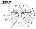
図8と図9で示される例示的実施形態において、サセプタ主面3と最下段被覆プレート6との間のギャップ11を形成する際に、シャフト18’と頭部18”を有する位置決め部材18は、最下段被覆プレート6をサセプタ2と結合させるために、最下段被覆プレート6の開口部23からのみ、到達する。この目的のため、サセプタ2は挿入穴24を有し、シャフト18’の下端はその中へと挿入される。In the exemplary embodiment shown in Figures 8 and 9, when forming the
図8から図9に加えて図11から図13にて例示的実施形態を示す。そこで最上段被覆プレート7は、最下段被覆プレート6よりも表面の広がりが小さい。同様に、二つの被覆プレート6、7が構成する積層が、二つの位置決め部材18のみによってサセプタと結合するように設けられる。位置決め部材18のシャフト18’が通る開口部23は、位置決め部材18のシャフト18’よりも幾分直径が大きくなりうる。サセプタ構造の構成要素が、サセプタ2が熱せられる際に、相互に移動できるようにするためである。8-9 as well as 11-13 show an exemplary embodiment, in which the
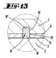
図11から図13は、おおよそで三角形の最上段被覆プレート7の最下段被覆プレート6への取り付けを示している。最上段被覆プレート7は、最下段被覆プレート上に水平に置かれる。最上段被覆プレート7は二つの止まり穴9、10を有する。これらは最上段被覆プレート7の下側に位置する。第一の止まり穴10は、円柱ピンの形状をもつ位置決め部材8の上部8”に適合するよう形成される。そしてその下部8’は、最下段被覆プレート6の形状的に篏合する開口部13へと挿入される。最上段被覆プレート7の下側にある第二の止まり穴9は、 横長穴として設計される。これは二つの被覆プレート6、7が、熱膨張したとき相互において移動できるようにするためである。最下段被覆プレート6と最上段被覆プレート7は、厳密に二つの位置決め部材8により相互に結合している。位置決め部材8は、サセプタ2における回転の中心に関して、おおよそ径方向に前後して配置される。しかしながら、位置決め部材8は相互に隣り合って配置することもできる。例えば方位方向に相互隣り合って配置することができる。Figures 11 to 13 show the attachment of a roughly triangular
位置決め部材8の下部8’の一つの端面は、サセプタ2の主面3上で、それ自身を支持することができる。たとえ好ましくない変形例において可能であった場合でも、最上段被覆プレート7は、位置決め部材8の上部8”の端面上で支持すべきではない。好ましくない変形において、第二の止まり穴9、10のそれぞれの底面は、この端面上でそれ自身を支持しうる。これは最上段被覆プレート7をギャップによって最下段被覆プレート6から離れて置くことを可能にするだけではない。二つのピン形状の位置決め部材8は、最上段被覆プレート7によって完全に覆われ得ることも可能である。しかしながら、最上段被覆プレート7は最下段被覆プレート6の上に置くことが望ましい。結果として、上部8”の端面と止まり穴9、10の底との間の距離が存在することになる。One end face of the lower part 8' of the
ここでも、位置決め部材8は炭化ケイ素からなる。しかしながら位置決め部材8はプロセスチャンバにさらされない限り、サファイアからなることが望ましい。Again, the positioning
最下段被覆プレート6をサセプタ2に固定する二つの位置決め部材18は、直線を形成し、最下段被覆プレート6の二つの開口部23を通る。最上段被覆プレート7を最下段被覆プレート6に固定する二つの位置決め部材8は、同様に直線を形成する。二つの直線は相互に直交する。The two
最下段被覆プレート6は、最下段被覆プレート16と外形を一致させることができる。最下段被覆プレート6は、二つの部分を有し、部分的に二つのポケット22を取り囲むように、その外周縁は円弧ライン上を走る。The
最下段被覆プレート6上に置かれる最上段被覆プレート7は、鋭角に交わり、直線に沿ってのびる二つの縁30を有する。当該縁30は、それぞれチャネル31の側面に位置する。そのチャネル31内に把持アームのフォークの又に分かれたアームが係合できる。それにより基板ホルダ4は、それを格納するポケット22から持ち上げることができる。The
図2と図3では、同様にポケット22の側面に位置する丸い縁を有するさらに別の被覆プレート25、26を示す。Figures 2 and 3 show further covering
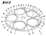
図14では、サセプタ2上に配列した五つの基板ホルダ4を有するサセプタ2を示す。それぞれ格納ポケットに格納される。最下段被覆プレート6は、そのようにアーチ形の外周縁を有するように設計される。それにより、二つの基板ホルダ4又は格納ポケットは、部分的に取り囲まれる。この例示的実施形態において、格納ポケット又はその中に配置される基板ホルダ4は、四つの被覆プレートの全体によって部分的に取り囲まれる。具体的には、二つの径方向外側の被覆プレート6と二つの径方向内側の被覆プレート25である。ギャップ33が形成され、そこで、二つの半径方向外側の被覆プレート6は相互に隣接する。In FIG. 14, a
図15は、基板ホルダ4又は基板ホルダ4を格納する格納ポケットが、3つの被覆プレート36、25と隣接するような、サセプタ2についての例示的実施形態を示す。径方向外側の被覆プレート36は、基板ホルダ4を部分的に取り囲む円弧型の開口部を有する。この例示的実施形態において、基板ホルダ4は、厳密に一つの径方向外側の被覆プレート36によって部分的に取り囲まれる。Figure 15 shows an exemplary embodiment of a
被覆プレート36は、上段被覆プレート又は厳密に一つの上段被覆プレートを置くことができるような、下段被覆プレートである。二つの隣接する被覆プレート36の間に、追加的に、おおよそ三角形の被覆プレート34が設けられ、それはギャップ35の構造を有する二つの被覆プレート36と隣接する。この例示的実施形態において、被覆プレート34は、基板ホルダ4と隣接しない。The covering
上記の記述は、本出願が全体として範囲とする発明を説明するのに役立ち、本発明はそれぞれの場合において、独立して、少なくとも特徴の組み合わせによって、先行技術を発展させるものであり、これらの特徴の組み合わせのうち、二つ、複数又は全てを組み合わせることも可能である。The above description serves to explain the invention covered by this application as a whole, which in each case independently develops the prior art by at least a combination of features, of which two, several or all combinations of features are also possible.
サセプタ2の第一主面3に隣接する最下段被覆プレート6、16、36と、最下段被覆プレート6、16、36と少なくとも部分的に重なり、サセプタ構造の自由主面14を形成する最上段被覆プレート7、17とを含む少なくとも一つの被覆体5、15により、特徴づけられるサセプタ構造。A susceptor structure characterized by at least one
二つの被覆プレート6、16、36、7、17が、炭化ケイ素、クオーツ、Al2O3、ZrO2、炭化ケイ素被覆黒鉛、又はその他の適切なセラミックの、結晶又は非晶質物質からなることを特徴とするサセプタ構造。 A susceptor structure characterised in that the two
最下段被覆プレート6が、最上段被覆プレート7よりも大きな表面を有し、最上段被覆プレート7が、最下段被覆プレート6上に水平に置かれることを特徴とするサセプタ構造。A susceptor structure characterized in that the
基板ホルダ4を格納するための第一のサセプタ主面3上の格納ポケット22において、少なくとも一つの最下段被覆プレート6が二つの異なる格納ポケット22又は、一つ又は厳密に一つの格納ポケット22を部分的に取り囲むことを特徴とするサセプタ構造。A susceptor structure characterized in that in the storage pockets 22 on the first susceptor
少なくとも二つの格納ポケット22を部分的に取り囲む最下段被覆プレート16と、最下段被覆プレート16によって担持される最上段被覆プレート17とが同じレイアウトを有することを特徴とするサセプタ構造。A susceptor structure characterized in that a
最上段被覆プレート7、17を最下段被覆プレート6、15、36と結合するためのかつ/又は少なくとも一つの最下段被覆プレート6、16とその上に置かれる最上段被覆プレート7、17をサセプタ2に結合するための一つ以上の位置決め部材8、18を特徴とするサセプタ。A susceptor characterized by one or
位置決め部材18が、第一のサセプタ主面3の挿入穴24へ挿入することのできるシャフト18’を形成し、とりわけシャフト18’がスペーサ20の開口部を通過する位置まで到達するように設けられ、それとともに、最下段被覆プレート6、16、36は、第一のサセプタ主面3とのギャップ距離に配置され、かつ/又は、位置決め部材18が、シャフト18’に関して直径を広げた頭部18”を有しかつ最上段被覆プレート17又は最下段被覆プレート16の上に載置される、ことを特徴とするサセプタ構造。A susceptor structure characterized in that the positioning
最下段被覆プレート6、16、36は相互に離れて位置する二つの開口部12、13を有し、その中に、それぞれ形状的に篏合する位置決め部材8の下部8’が係合する。その端面は、第一のサセプタ主面3上に面し、かつ最上段被覆プレート7は、そこに対応する開口部を有し、最上段被覆プレート7の第一の開口部10は、位置決め部材の上部8”に形状的に篏合し、かつ第二の開口部9は、横長穴として形成され、とりわけ止まり穴によって形成される最上段被覆プレート7の二つの開口部9、10が設けられる、ことを特徴とするサセプタ構造。The
最上段被覆プレート7、17が、最下段被覆プレート6、16、36と直接隣接することを特徴とするサセプタ構造。A susceptor structure characterized in that the
とりわけ先行する請求項1及び請求項4~8のいずれかに記載された、CVDリアクタであって、サセプタ2の第一主面3と直接隣接する最下段被覆プレート6、16、36を有する少なくとも一つの被覆体5、15と、最下段被覆プレート6、16、36を覆い、サセプタ構造の自由主面を形成する、最上段被覆プレート7、17とを特徴とするCVDリアクタ。 A CVD reactor, in particular as described in any of the preceding
開示された全ての特徴は、(それ自体のために、また互いに組み合わされて)本発明に不可欠である。ここでの出願の開示は、関連する/追加された優先権書類(先の出願の写し)の開示内容をその内容全体に含み、それはこれらの書類の特徴を本願の請求項に組み込む目的でもある。従属請求項は、特にこれらの請求項に基づいて分割出願を行うために、引用される請求項の特徴がなくても、先行技術の独立した発明性のあるさらなる発展を特徴とする。各請求項で特定された発明は、前述の説明で特定された、特に参照符号の付与、及び/又は参照番号のリストで特定された、1つ以上の機能を追加で有することができる。本発明はまた、特に、それらがそれぞれの使用目的に明らかに不要であるか、又は技術的に同じ効果を有する他の手段で置き換えることができる限り、前述の説明で述べた特徴の個々のものが実装されていない、設計の形態に関する。All disclosed features are essential to the invention (both by themselves and in combination with one another). The disclosure of the present application includes in its entirety the disclosure content of the relevant/added priority documents (copies of the earlier application), also with a view to incorporating the features of these documents in the claims of the present application. The dependent claims are characterized by an independent, inventive further development of the prior art, even without the features of the claims cited, in particular in order to file a divisional application on the basis of these claims. The invention specified in each claim may additionally have one or more features specified in the preceding description, in particular by the assignment of reference signs and/or by the list of reference numbers. The present invention also relates in particular to forms of design in which individual ones of the features mentioned in the preceding description are not implemented, insofar as they are obviously unnecessary for the respective intended use or can be replaced by other means having the same technical effect.
1 CVDリアクタ
2 サセプタ
3 第一主面
4 基板ホルダ
5 被覆体
6 最下段被覆プレート
7 最上段被覆プレート
8 位置決め部材
8’ 下部
8” 上部
9 横長穴、 止まり穴
10 形成止まり穴
11 ギャップ
12 開口部
13 開口部
14 自由主面
15 被覆体
16 最下段被覆プレート
17 最上段被覆プレート
18 位置決め部材
19 開口部
20 スペーサ
21 ソケット
22 ポケット
23 開口部
24 挿入穴
25 被覆プレート
26 被覆プレート
27 ガス入口部材
28 プロセスチャンバ
29 加熱装置
30 縁
31 チャネル
32 キャリア
33 ギャップ
34 被覆プレート
35 ギャップ
36 下段被覆プレート LIST OF SYMBOLS 1
Claims (9)
Translated fromJapanese第一のサセプタ主面(3)を有する円状又は環状のサセプタ(2)を備え、
前記第一のサセプタ主面(3)上には、基板ホルダ(4)と少なくとも一つの被覆体(5、15)とが配置され、
前記被覆体(5、15)は、前記サセプタ(2)の前記第一のサセプタ主面(3)に隣接する、最下段被覆プレート(6、16、36)と、前記最下段被覆プレート(6、16、36)と少なくとも局所的に重なり、前記サセプタ構造の自由主面(14)を形成する最上段被覆プレート(7、17)とを具備する、前記サセプタ構造において、
相互に合わさる、前記最下段被覆プレート(6、16、36)と前記最上段被覆プレート(7、17)との開口部(12、13;19、9、10)へ挿入される一つ又は複数の位置決め部材(8、18)によって、前記最上段被覆プレート(7、17)は、前記最下段被覆プレート(6、16、36)に結合し、かつ/又は、前記最下段被覆プレート(6、16、36)とその上に載置される前記最上段被覆プレート(7、17)とが前記サセプタ(2)に結合すること、を特徴とする、サセプタ構造。 A susceptor structure for use in a CVD reactor (1), comprising:
A circular or annular susceptor (2) having a first susceptor main surface (3),
A substrate holder (4) and at least one coating (5, 15) are disposed on thefirst susceptor main surface(3) ;
The covering body (5, 15) comprises a lowermost covering plate (6, 16, 36) adjacent to thefirst susceptor main surface (3) of the susceptor (2) and an uppermost covering plate (7, 17) at least locally overlapping the lowermost covering plate (6, 16, 36) and forming a free main surface (14) of the susceptor structure,
a lowermost covering plate (6, 16, 36) and auppermost covering plate (7, 17) are connectedto the lowermost covering plate (6, 16, 36) by one or more positioning members (8, 18) inserted into openings (12, 13; 19, 9,10 ) of the lowermost covering plate (6, 16, 36) and the uppermost covering plate (7, 17), which fit together with each other, and/or the lowermost covering plate (6, 16, 36) and the uppermost covering plate (7, 17) placed thereon are connected to the susceptor (2).
第一主面(3)を有する円状又は環状のサセプタ(2)を備え、前記第一主面(3)上に基板ホルダ(4)と少なくとも一つの被覆体(5、15)が配置され、前記第一主面(3)の反対側に位置する第二主面(3)が加熱装置(26)によって加熱可能である、サセプタ構造と、を備えるCVDリアクタであって、
少なくとも一つの前記被覆体(5、15)が、前記サセプタ(2)の前記第一主面(3)に直接隣接する最下段被覆プレート(6、16、36)と、
前記最下段被覆プレート(6、16、36)を覆い、請求項1~8のいずれかに記載のサセプタ構造の自由主面を形成する、最上段被覆プレート(7、17)と、を具備することを特徴とするCVDリアクタ。
a gas inlet member (27) for injecting process gas into the process chamber (28);
a susceptor structure comprising a circular or annular susceptor (2) having a first main surface (3), on which a substrate holder (4) and at least one coating (5, 15) are arranged, and a second main surface (3) located opposite to the first main surface (3) is heatable by a heating device (26),
a lowermost covering plate (6, 16, 36) in which at least one of the covering bodies (5, 15) is directly adjacent to the first main surface (3) of the susceptor (2);
a top covering plate (7, 17) covering said bottom covering plate (6, 16, 36) and forming a free main surface of the susceptor structure according to any one of claims 1 to 8.
Applications Claiming Priority (3)
| Application Number | Priority Date | Filing Date | Title |
|---|---|---|---|
| DE102019105913.5ADE102019105913A1 (en) | 2019-03-08 | 2019-03-08 | Susceptor arrangement of a CVD reactor |
| DE102019105913.5 | 2019-03-08 | ||
| PCT/EP2020/055308WO2020182495A1 (en) | 2019-03-08 | 2020-02-28 | Susceptor arrangement of a cvd reactor |
Publications (2)
| Publication Number | Publication Date |
|---|---|
| JP2022523594A JP2022523594A (en) | 2022-04-25 |
| JP7539401B2true JP7539401B2 (en) | 2024-08-23 |
Family
ID=69780155
Family Applications (1)
| Application Number | Title | Priority Date | Filing Date |
|---|---|---|---|
| JP2021553376AActiveJP7539401B2 (en) | 2019-03-08 | 2020-02-28 | CVD reactor susceptor structure |
Country Status (6)
| Country | Link |
|---|---|
| US (1) | US12110591B2 (en) |
| EP (1) | EP3935201A1 (en) |
| JP (1) | JP7539401B2 (en) |
| DE (1) | DE102019105913A1 (en) |
| TW (1) | TWI858027B (en) |
| WO (1) | WO2020182495A1 (en) |
Families Citing this family (3)
| Publication number | Priority date | Publication date | Assignee | Title |
|---|---|---|---|---|
| DE102018114208A1 (en) | 2018-06-14 | 2019-12-19 | Aixtron Se | Cover plate for covering the side of a susceptor of a device for depositing SiC layers facing the process chamber |
| DE102019114249A1 (en)* | 2018-06-19 | 2019-12-19 | Aixtron Se | Arrangement for measuring the surface temperature of a susceptor in a CVD reactor |
| DE102020123326A1 (en) | 2020-09-07 | 2022-03-10 | Aixtron Se | CVD reactor with temperature-controlled gas inlet area |
Citations (3)
| Publication number | Priority date | Publication date | Assignee | Title |
|---|---|---|---|---|
| JP2007501329A (en) | 2003-05-22 | 2007-01-25 | アイクストロン、アーゲー | CVD coating equipment |
| JP2016035080A (en) | 2014-08-01 | 2016-03-17 | 大陽日酸株式会社 | Susceptor cover and vapor phase growth apparatus provided with the susceptor cover |
| JP2018022880A (en) | 2016-06-07 | 2018-02-08 | アプライド マテリアルズ インコーポレイテッドApplied Materials,Incorporated | Contour pocket and hybrid susceptor for wafer uniformity |
Family Cites Families (13)
| Publication number | Priority date | Publication date | Assignee | Title |
|---|---|---|---|---|
| JPH05267277A (en)* | 1992-03-23 | 1993-10-15 | Hitachi Electron Eng Co Ltd | Plasma cvd apparatus |
| DE10043600B4 (en)* | 2000-09-01 | 2013-12-05 | Aixtron Se | Device for depositing in particular crystalline layers on one or more, in particular also crystalline substrates |
| JP4441356B2 (en) | 2003-10-16 | 2010-03-31 | 東京エレクトロン株式会社 | Deposition equipment |
| JP2006173560A (en)* | 2004-11-16 | 2006-06-29 | Sumitomo Electric Ind Ltd | Wafer guide, metal organic chemical vapor deposition apparatus, and method for depositing nitride-based semiconductor |
| DE102005055252A1 (en)* | 2005-11-19 | 2007-05-24 | Aixtron Ag | CVD reactor with slide-mounted susceptor holder |
| DE102006018514A1 (en)* | 2006-04-21 | 2007-10-25 | Aixtron Ag | Apparatus and method for controlling the surface temperature of a substrate in a process chamber |
| JP5613083B2 (en)* | 2011-02-28 | 2014-10-22 | 大陽日酸株式会社 | Susceptor cover and vapor phase growth apparatus provided with the susceptor cover |
| JP2013004593A (en)* | 2011-06-14 | 2013-01-07 | Sharp Corp | Substrate support apparatus and vapor deposition apparatus |
| DE102014104218A1 (en)* | 2014-03-26 | 2015-10-01 | Aixtron Se | CVD reactor with feed-zone temperature control |
| US9738974B2 (en)* | 2014-06-02 | 2017-08-22 | Epistar Corporation | Susceptor |
| EP3574127A1 (en)* | 2017-01-27 | 2019-12-04 | Aixtron SE | Transport ring |
| DE102018113400A1 (en)* | 2018-06-06 | 2019-12-12 | Aixtron Se | CVD reactor with support ring for substrate handling |
| DE102019114249A1 (en)* | 2018-06-19 | 2019-12-19 | Aixtron Se | Arrangement for measuring the surface temperature of a susceptor in a CVD reactor |
- 2019
- 2019-03-08DEDE102019105913.5Apatent/DE102019105913A1/enactivePending
- 2020
- 2020-02-28WOPCT/EP2020/055308patent/WO2020182495A1/ennot_activeCeased
- 2020-02-28USUS17/593,081patent/US12110591B2/enactiveActive
- 2020-02-28JPJP2021553376Apatent/JP7539401B2/enactiveActive
- 2020-02-28EPEP20710074.4Apatent/EP3935201A1/enactivePending
- 2020-03-04TWTW109107000Apatent/TWI858027B/enactive
Patent Citations (3)
| Publication number | Priority date | Publication date | Assignee | Title |
|---|---|---|---|---|
| JP2007501329A (en) | 2003-05-22 | 2007-01-25 | アイクストロン、アーゲー | CVD coating equipment |
| JP2016035080A (en) | 2014-08-01 | 2016-03-17 | 大陽日酸株式会社 | Susceptor cover and vapor phase growth apparatus provided with the susceptor cover |
| JP2018022880A (en) | 2016-06-07 | 2018-02-08 | アプライド マテリアルズ インコーポレイテッドApplied Materials,Incorporated | Contour pocket and hybrid susceptor for wafer uniformity |
Also Published As
| Publication number | Publication date |
|---|---|
| JP2022523594A (en) | 2022-04-25 |
| US12110591B2 (en) | 2024-10-08 |
| TWI858027B (en) | 2024-10-11 |
| WO2020182495A1 (en) | 2020-09-17 |
| TW202039904A (en) | 2020-11-01 |
| EP3935201A1 (en) | 2022-01-12 |
| DE102019105913A1 (en) | 2020-09-10 |
| KR20210149728A (en) | 2021-12-09 |
| US20220186374A1 (en) | 2022-06-16 |
Similar Documents
| Publication | Publication Date | Title |
|---|---|---|
| JP7539401B2 (en) | CVD reactor susceptor structure | |
| US8461062B2 (en) | Substrate processing apparatus and method for manufacturing semiconductor device | |
| CN1489644A (en) | Susceptorless reactor for growing epitaxial layers on wafers by chemical vapor deposition | |
| TWI488258B (en) | Enhanced wafer carrier | |
| US12180590B2 (en) | Cover plate for covering the susceptor side facing the process chamber of a device for depositing SiC layers | |
| US7314526B1 (en) | Reaction chamber for an epitaxial reactor | |
| KR20040101400A (en) | Gas driven planetary rotation apparatus and methods for forming silicon carbide layers | |
| KR20100102185A (en) | Susceptor with support bosses | |
| EP2397575B1 (en) | Cvd device | |
| JP2004525056A5 (en) | ||
| US20110056434A1 (en) | Heat treatment apparatus | |
| KR20030097861A (en) | Assembly comprising heat distributing plate and edge support | |
| TW201820512A (en) | Substrate processing device and method | |
| TW202006184A (en) | Arrangement for measuring the surface temperature of a susceptor in a CVD reactor | |
| KR101412034B1 (en) | Gas injection assembly and thin film deposition apparatus using the same | |
| JP2016063091A (en) | Substrate processing method, substrate processing apparatus, and program | |
| KR101455736B1 (en) | Substrate supporting member, apparatus for treating substrate with it | |
| KR102871297B1 (en) | Susceptor array of a CVD reactor | |
| TWI821766B (en) | Thin film growth systems and substrate tray and carrier ring elements | |
| JP2015195259A (en) | Susceptor and vapor phase growth device | |
| US20230290669A1 (en) | Semiconductor manufacturing apparatus | |
| KR20090047625A (en) | Susceptors for Chemical Vapor Deposition Devices | |
| KR20240076789A (en) | CVD-reactor with support ring and support ring for substrate | |
| US20140230734A1 (en) | Deposition apparatus | |
| KR20210045025A (en) | Substrate processing apparatus |
Legal Events
| Date | Code | Title | Description |
|---|---|---|---|
| A521 | Request for written amendment filed | Free format text:JAPANESE INTERMEDIATE CODE: A523 Effective date:20211109 | |
| A621 | Written request for application examination | Free format text:JAPANESE INTERMEDIATE CODE: A621 Effective date:20230202 | |
| A977 | Report on retrieval | Free format text:JAPANESE INTERMEDIATE CODE: A971007 Effective date:20240129 | |
| A131 | Notification of reasons for refusal | Free format text:JAPANESE INTERMEDIATE CODE: A131 Effective date:20240219 | |
| A521 | Request for written amendment filed | Free format text:JAPANESE INTERMEDIATE CODE: A523 Effective date:20240416 | |
| TRDD | Decision of grant or rejection written | ||
| A01 | Written decision to grant a patent or to grant a registration (utility model) | Free format text:JAPANESE INTERMEDIATE CODE: A01 Effective date:20240724 | |
| A61 | First payment of annual fees (during grant procedure) | Free format text:JAPANESE INTERMEDIATE CODE: A61 Effective date:20240813 | |
| R150 | Certificate of patent or registration of utility model | Ref document number:7539401 Country of ref document:JP Free format text:JAPANESE INTERMEDIATE CODE: R150 |