JP7539033B2 - Liquid Treatment Equipment - Google Patents
Liquid Treatment EquipmentDownload PDFInfo
- Publication number
- JP7539033B2 JP7539033B2JP2020180456AJP2020180456AJP7539033B2JP 7539033 B2JP7539033 B2JP 7539033B2JP 2020180456 AJP2020180456 AJP 2020180456AJP 2020180456 AJP2020180456 AJP 2020180456AJP 7539033 B2JP7539033 B2JP 7539033B2
- Authority
- JP
- Japan
- Prior art keywords
- protective tube
- discharge lamp
- barrier discharge
- tube
- liquid
- Prior art date
- Legal status (The legal status is an assumption and is not a legal conclusion. Google has not performed a legal analysis and makes no representation as to the accuracy of the status listed.)
- Active
Links
Images


Landscapes
- Physical Water Treatments (AREA)
Description
Translated fromJapanese本発明の実施形態は、液体処理装置に関する。An embodiment of the present invention relates to a liquid treatment device.
液体中にある不純物を除去する方法として、濾過法、活性炭吸着法、イオン交換法、蒸留法、逆浸透膜脱塩法などが知られている。近年においては、紫外線を用いた不純物の除去も行われている。例えば、紫外線を水に照射すると、酸化力の強いヒドロキシルラジカルが生成される。ヒドロキシルラジカルは、水中にある全有機炭素(TOC:Total Organic Carbon)を有機酸を経て二酸化炭素に分解するので、濾過法などに比べてより純度の高い純水を製造することができる。Methods for removing impurities from liquids include filtration, activated carbon adsorption, ion exchange, distillation, and reverse osmosis desalination. In recent years, impurities have also been removed using ultraviolet light. For example, irradiating water with ultraviolet light produces hydroxyl radicals, which have strong oxidizing power. Hydroxyl radicals break down the total organic carbon (TOC) in the water into carbon dioxide via organic acids, making it possible to produce pure water with a higher purity than methods such as filtration.
紫外線を水に照射して不純物の除去を行う技術は、例えば、半導体装置などの電子部品の洗浄工程において用いられている。この様な工程において用いられる原料水の純度は高く、TOC濃度は100ppb程度であるが、紫外線を原料水に照射することで、TOC濃度を10ppb程度にまで低下させることができる。
また、紫外線を水に照射することで生成されたヒドロキシルラジカルは、菌やウイルスの殺菌や不活性化にも効果がある。そのため、紫外線を水に照射する技術は、前述した不純物の除去とは別に、あるいは不純物の除去とともに、水の殺菌処理などにも用いられている。 The technology of removing impurities by irradiating water with ultraviolet light is used, for example, in the cleaning process of electronic components such as semiconductor devices. The raw water used in such processes has a high purity and a TOC concentration of about 100 ppb, but by irradiating the raw water with ultraviolet light, the TOC concentration can be reduced to about 10 ppb.
In addition, the hydroxyl radicals generated by irradiating water with ultraviolet light are also effective in killing and inactivating bacteria and viruses. Therefore, the technology of irradiating water with ultraviolet light is used for water sterilization treatment, either separately or in addition to removing the impurities mentioned above.
ここで、紫外線を照射する光源としては、ピーク波長が254nmの紫外線、または、ピーク波長が185nm及び254nmの紫外線を照射する低圧水銀ランプが用いられていた。しかしながら、水の紫外線吸収係数は、波長が500nm近傍で最小となり、500nmより長波長側または短波長側へシフトするにつれて増加する。そのため、ピーク波長が172nmの紫外線を照射するバリア放電ランプ(キセノンエキシマランプ)が用いられるようになってきている。Here, the light source used to irradiate ultraviolet light was a low-pressure mercury lamp that irradiates ultraviolet light with a peak wavelength of 254 nm, or ultraviolet light with peak wavelengths of 185 nm and 254 nm. However, the ultraviolet absorption coefficient of water is minimum at wavelengths around 500 nm, and increases as the wavelength shifts from 500 nm toward the longer or shorter wavelength side. For this reason, barrier discharge lamps (xenon excimer lamps) that irradiate ultraviolet light with a peak wavelength of 172 nm have come to be used.
バリア放電ランプが処理を施す液体中に設けられていれば、液体に紫外線を直接照射することができるので、液体の処理を効率よく行うことができる。ところが、単に、バリア放電ランプを液体中に設ければ、処理流量が低下したり、ヒドロキシルラジカルの濃度が低下したりして処理能力が低下するおそれがある。
そこで、処理能力の向上を図ることができる液体処理装置の開発が望まれていた。 If a barrier discharge lamp is provided in the liquid to be treated, the liquid can be directly irradiated with ultraviolet light, and the liquid can be treated efficiently. However, simply providing a barrier discharge lamp in the liquid may reduce the treatment flow rate or the concentration of hydroxyl radicals, resulting in a decrease in treatment capacity.
Therefore, there has been a demand for the development of a liquid treatment device that can improve the treatment capacity.
本発明が解決しようとする課題は、処理能力の向上を図ることができる液体処理装置を提供することである。The problem that this invention aims to solve is to provide a liquid treatment device that can improve the treatment capacity.
実施形態に係る液体処理装置は、液体に紫外線を照射する液体処理装置であって、前記液体が供給される空間を内部に有する容器と;前記空間に設けられ、第1の方向に延びる形状を有し、第1のバリア放電ランプが収納される第1の保護管と;前記空間に設けられ、前記第1の方向に延びる形状を有し、第2のバリア放電ランプが収納される第2の保護管と;を具備している。前記第1の方向に直交する断面において、前記第1の保護管と、前記容器の内壁と、の間の距離L(mm)が、以下の式を満足する。前記容器の内壁は、前記第1の保護管と略同芯に設けられた第1の部分と、前記第2の保護管と略同芯に設けられた第2の部分と、を有している。前記第1の方向に直交する断面において、前記第1の保護管と、前記第1の部分と、の間の距離L1(mm)、および、前記第2の保護管と、前記第2の部分と、の間の距離L2(mm)が、以下の式を満足する。
3mm≦L(mm)≦15mm
3mm≦L1(mm)≦15mm
3mm≦L2(mm)≦15mm A liquid treatment device according to an embodiment is a liquid treatment device that irradiates a liquid with ultraviolet light, and includes a container having a space therein to which the liquid is supplied; a first protective tube provided in the space, having a shape extending in a first direction, and housing a first barrier discharge lamp; and a second protective tube provided in the space, having a shape extending in the first direction, and housing a second barrier discharge lamp . In a cross section perpendicular to the first direction, a distance L (mm) between the first protective tube and an inner wall of the container satisfies the followingformula. The inner wall of the container has a first portion provided substantially concentrically with the first protective tube and a second portion provided substantially concentrically with the second protective tube. In a cross section perpendicular to the first direction, a distance L1 (mm) between the first protective tube and the first portion, and a distance L2 (mm) between the second protective tube and the second portion satisfy the following formula.
3mm≦L(mm)≦15mm
3mm≦L1 (mm)≦15mm
3mm≦L2 (mm)≦15mm
本発明の実施形態によれば、処理能力の向上を図ることができる液体処理装置を提供することができる。According to an embodiment of the present invention, it is possible to provide a liquid treatment device that can improve the processing capacity.
以下、図面を参照しつつ、実施の形態について例示をする。なお、各図面中、同様の構成要素には同一の符号を付して詳細な説明は適宜省略する。Below, an embodiment will be illustrated with reference to the drawings. Note that in each drawing, similar components are given the same reference numerals and detailed explanations are omitted as appropriate.
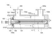
図1は、本実施の形態に係る液体処理装置100を例示するための模式断面図である。 図2は、図1における液体処理装置100のA-A線方向の模式断面図である。
液体処理装置100は、液体300に紫外線を照射する。
図1に示すように、液体処理装置100には、例えば、バリア放電ランプ1(第1のバリア放電ランプの一例に相当する)、保護管101(第1の保護管の一例に相当する)、蓋102、シール部材103、容器104、ホルダ105、およびシール部材106を設けることができる。 Fig. 1 is a schematic cross-sectional view illustrating a
The
As shown in FIG. 1, the
まず、バリア放電ランプ1について例示をする。
図3(a)は、バリア放電ランプ1を例示するための模式図である。
図3(b)は、図3(a)におけるバリア放電ランプ1のB部の模式拡大図である。
図4は、図3(a)におけるバリア放電ランプ1のC-C線方向の模式断面図である。 図3(a)、図3(b)、および図4に示すように、バリア放電ランプ1には、例えば、発光管2、導電部3、内部電極4、アンカ5、ホルダ6、外部電極7、リード線8、およびリード線9を設けることができる。 First, the
FIG. 3A is a schematic diagram illustrating the
FIG. 3B is a schematic enlarged view of the portion B of the
Fig. 4 is a schematic cross-sectional view of the
発光管2は、筒状を呈し、管径に比べて全長(管軸方向の長さ)が長い形態を有する。発光管2は、例えば、円筒管とすることができる。発光管2の外径は、例えば、10mm以上、25mm以下とすることができる。発光管2の肉厚は、例えば、1mm程度とすることができる。発光管2の長さは、液体処理装置100の仕様などに応じて適宜変更することができる。例えば、発光管2の長さは、1300mm程度とすることができる。The
発光管2の、管軸方向における両側の端部のそれぞれには、封止部2aが設けられている。封止部2aを設けることで、発光管2の内部空間を気密に封止することができる。封止部2aは、例えば、ピンチシール法やシュリンクシール法を用いて形成することができる。A sealing
発光管2の外面には、突起部2bを設けることができる。突起部2bは、バリア放電ランプ1を製造する際に、発光管2の内部空間を排気したり、発光管2の内部空間に後述するガスを導入したりするために設けることができる。突起部2bは、排気およびガスの導入後に、合成石英ガラスから形成された管を焼き切ることで形成されたものとすることができる。The outer surface of the
発光管2の内部空間には、ガスが封入されている。バリア放電ランプ1においては、内部電極4と外部電極7との間で誘電体バリア放電を行って、封入されているガスに高いエネルギー電子を与えてエキシマ励起分子を生成する。エキシマ励起分子が元に戻る際に、ガスの種類に応じて特定のピーク波長を有する光が発生する。そのため、発光管2の内部空間に封入するガスは、バリア放電ランプ1の用途に応じて適宜変更することができる。発光管2の内部空間に封入するガスは、例えば、クリプトン、キセノン、アルゴン、ネオンなどの希ガス、あるいは、複数種類の希ガスを混合させた混合ガスとすることができる。ガスには、必要に応じて、ハロゲンガスなどをさらに含めることもできる。Gas is sealed in the internal space of the
発光管2の内部空間の25℃におけるガスの圧力(封入圧力)は、例えば、1.3kPa~200kPa程度とすることができる。発光管2の内部空間の25℃におけるガスの圧力(封入圧力)は、気体の標準状態(SATP(Standard Ambient Temperature and Pressure):温度25℃、1bar)により求めることができる。The gas pressure (filled pressure) in the internal space of the
例えば、水などの液体に含まれている有機物などの不純物を分解する場合には、封入するガスをキセノンとすることが好ましい。キセノンの封入圧力は、例えば、93kPa程度とすることができる。封入するガスをキセノンとすれば、ピーク波長が172nmの紫外線を発生させることができるので不純物の分解を効果的に行うことができる。また、ピーク波長が短い紫外線が照射されるので、菌やウイルスの殺菌や不活性化にも有効である。For example, when decomposing impurities such as organic matter contained in liquids such as water, it is preferable to use xenon as the enclosed gas. The xenon sealing pressure can be, for example, about 93 kPa. If the enclosed gas is xenon, ultraviolet rays with a peak wavelength of 172 nm can be generated, so impurities can be effectively decomposed. In addition, since ultraviolet rays with a short peak wavelength are irradiated, it is also effective in sterilizing and inactivating bacteria and viruses.
発光管2の内部空間において発生した紫外線は、発光管2を介して外部に照射される。そのため、発光管2は、紫外線の透過率が高い材料から形成されている。紫外線の透過率が高い材料は、例えば、合成石英ガラスなどのSiO2を含む材料とすることができる。ところが、ピーク波長が172nmの紫外線がSiO2を含む材料に入射すると、経時的に、材料の化学的な構造が変化する場合がある。例えば、SiO2に紫外線が入射すると、SiとOの結合が切れる場合がある。そのため、バリア放電ランプ1を長時間点灯させると、発光管2の材料の化学的な構造に欠陥が生じて、紫外線の透過率の急激な低下、ひいては、照度維持率が低下するおそれがある。 The ultraviolet light generated in the internal space of the
本発明者の得た知見によれば、SiO2を含む材料に含まれるOH基の量を多くすれば、紫外線の入射により、SiとOの結合が切れたとしても、化学的な構造の欠陥を修復できる。ただし、OH基の含有量を多くし過ぎると紫外線の透過率が低下する場合がある。 According to the findings of the present inventors, if the amount of OH groups contained in a material containingSiO2 is increased, defects in the chemical structure can be repaired even if the bond between Si and O is broken by the incidence of ultraviolet light. However, if the content of OH groups is too high, the transmittance of ultraviolet light may decrease.
本発明者の得た知見によれば、発光管2は合成石英ガラスなどのSiO2を含む材料から形成され、OH基の含有量を100ppm以上、1500ppm以下とすることが好ましい。この様にすれば、発光管2の内部空間において、ピーク波長が172nmの紫外線が発生したとしても、長時間にわたり高い照度維持率を保つことができる。また、紫外線の透過率が低下するのを抑制することができる。 According to the findings of the present inventors, it is preferable that the
導電部3は、封止部2aの内部に設けられている。導電部3は、1つの封止部2aに対して1つ設けることができる。導電部3の平面形状は四角形とすることができる。導電部3は、薄膜状を呈している。導電部3は、例えば、モリブデン箔から形成することができる。The
内部電極4は、例えば、コイル4aおよびレグ4bを有する。コイル4aおよびレグ4bは、一体に形成することができる。コイル4aおよびレグ4bは、線材を塑性加工することで形成することができる。線材の線径(直径)は、例えば、0.2mm~1.0mm程度とすることができる。The
コイル4aおよびレグ4bは、例えば、タングステンを主成分として含んでいる。タングステンの含有量は、例えば、50wt%以上とすることができる。この場合、タングステンにカリウムなどを添加したドープタングステンを用いれば、コイル4aの寸法安定性を高めることができる。The
コイル4aは螺旋状を呈し、発光管2の内部空間に設けられている。コイル4aは、発光管2の内部空間の中央領域を発光管2の管軸に沿って延びている。発光管2の管軸方向における隣接する線材同士の間隔をコイル4aのピッチ寸法Pとすると、コイル4aのピッチ寸法Pは、例えば、0.5mm~3.0mm程度とすることができる。また、発光管2の管軸方向と直交する方向におけるコイル4aの外径Dは、例えば、1mm~5mm程度とすることができる。The
レグ4bは、コイル4aの両側の端部のそれぞれに設けられている。レグ4bは、線状を呈し、コイル4aの端部から発光管2の管軸に沿って延びている。レグ4bの端部は、封止部2aの内部において導電部3と電気的に接続されている。レグ4bの端部の近傍は、導電部3と、レーザ溶接または抵抗溶接することができる。The
アンカ5は、発光管2の内部空間に設けることができる。アンカ5の材料は、例えば、内部電極4の材料と同じとすることができる。アンカ5は、線材を塑性加工することで形成することができる。例えば、アンカ5の一方の端部側は、コイル4aの外面に設けることができる。例えば、アンカ5の一方の端部側を、コイル4aの外面に巻き付けることができる。例えば、アンカ5の一方の端部側は、螺旋状を呈するものとすることができる。例えば、アンカ5の他方の端部側は、発光管2の内壁に接触させることができる。例えば、アンカ5の他方の端部側は、発光管2の内壁に沿って湾曲した形状を有することができる。なお、アンカ5をコイル4aに取り付ける場合を例示したが、コイル4aの一部分の直径を大きくしてアンカ5としてもよい。The
アンカ5の一方の端部側がコイル4aの外面に設けられ、アンカ5の他方の端部側が発光管2の内壁に接触することで、アンカ5により、コイル4aが、発光管2の内部空間に支持される。また、アンカ5がコイル4aに電気的に接続されることで、アンカ5が内部電極4として機能する。すなわち、アンカ5は、コイル4aを支持するサポート部材、および内部電極4の一部として機能する。One end of the
アンカ5が内部電極4の一部として機能すれば、内部電極4(アンカ5)と外部電極7との間の距離が小さくなるので、低い始動電圧でも始動させることができる。また、低い維持電圧でも発光を維持することができる。すなわち、瞬時点灯性能が向上し、点灯状態も安定させることができる。また、内部電極4(アンカ5)と外部電極7との間の距離が小さくなれば、ランプ始動直後の安定性も向上する。そのため、ランプ始動直後の発光むらを抑制することができるので、ランプ始動直後の光を直ちに利用することができる。If the
アンカ5は、例えば、ランプの発光特性や始動特性、および、コイル4aの支持性能などを考慮して、複数設けることができる。この場合、発光管2の管軸方向における隣接するアンカ5同士の間隔をアンカ5のピッチ寸法とすると、アンカ5のピッチ寸法は、例えば、10mm~40mm程度とすることができる。The
ホルダ6は、筒状を呈し、一方の端部側が封止部2aの内部に設けられ、他方の端部側が封止部2aから露出している。ホルダ6は、1つの封止部2aに対して1つ設けることができる。ホルダ6は、例えば、樹脂や、セラミックスなどの無機材料から形成することができる。ホルダ6は、例えば、ステアタイト(steatite)、酸化アルミニウムなどを含むことができる。The
外部電極7は、発光管2の外部に設けることができる。外部電極7は、例えば、モネル、ステンレス、アルミニウム、ニッケル、銀、金、プラチナなどの金属を用いて形成することができる。外部電極7は、内部電極4との間で誘電体バリア放電を発生させる。前述したように、誘電体バリア放電が生じると、発光管2の内部空間においてエキシマ励起分子が生成され、エキシマ励起分子が元に戻る際に、ガスの種類に応じて特定のピーク波長を有する光が発生する。例えば、キセノンが封入されている場合には、ピーク波長が172nmの紫外線が発生する。The
この場合、発光管2の内部空間で発生した紫外線が外部電極7を透過することができれば、紫外線を発光管2の周囲の全方位に照射することができる。そのため、外部電極7は、例えば、厚み方向を貫通する孔やスリットなどが設けられたものとすることができる。この場合、外部電極7の遮光率は10%以下とすることが好ましい。In this case, if the ultraviolet light generated in the internal space of the light-emitting
例えば、図3(a)に示すように、外部電極7は、メッシュ状を呈している。例えば、外部電極7は、メリヤス編組構造を有している。メリヤス編組構造に用いられる線材は、例えば、線径が0.1mm程度のモネル線などとすることができる。メッシュ間隔は、例えば、縦が2.8mm程度、横が3mm程度とすることができる。For example, as shown in FIG. 3(a), the
メッシュ状の外部電極7とすれば、遮光率を10%以下とするのが容易となる。また、メッシュ状の外部電極7とすれば、発光管2の外面を覆うことができるので、内部電極4との対峙面積を大きくすることができる。そのため、誘電体バリア放電が、大面積にわたって安定的に生じ易くなる。By using a mesh-shaped
例えば、メッシュ状の金属を筒状に成形し、筒状の金属体の内部に発光管2を挿入することで、発光管2に外部電極7を設けることができる。For example, an
リード線8は、少なくとも一方のホルダ6に設けることができる。リード線8の一方の端部は、ホルダ6の内部を通り、封止部2aの内部において導電部3に電気的に接続されている。リード線8の一方の端部の近傍は、導電部3と、レーザ溶接または抵抗溶接することができる。また、リード線8とホルダ6との間の隙間は、封止材により封止されている。リード線8の他方の端部は、ホルダ6から露出させることができる。リード線8の他方の端部には、圧着端子やコネクタなどを接続することができる。The
リード線9の一方の端部は、ニッケルスリーブ9aを介して外部電極7に電気的に接続されている。リード線9の他方の端部には、圧着端子やコネクタなどを接続することができる。
リード線8とリード線9は、例えば、高周波電源などに電気的に接続することができる。高周波電源は、例えば、15kHz程度の正弦波を発生させる電源や、パルス電源などとすることができる。 One end of the
The
次に、図1および図2に戻って、液体処理装置100に設けられた他の要素について説明する。
バリア放電ランプ1を液体300の処理に用いる場合には、バリア放電ランプ1を液体300の中に直接設けることができない。そのため、図1に示すように、バリア放電ランプ1は保護管101の内部に収納される。
保護管101は、筒状を呈し、管径に比べて全長(管軸方向の長さ)が長い形態を有する。保護管101は、例えば、円筒管とすることができる。保護管101の一方の端部は塞がれ、他方の端部は開口している。保護管101の開口側の端部にはフランジ101a1を設けることができる。保護管101の内部空間には、バリア放電ランプ1が収納される。この場合、バリア放電ランプ1は、保護管101と略同芯となるように設けることが好ましい。保護管101の寸法は、収納されるバリア放電ランプ1(発光管2)に応じて適宜変更することができる。 Next, returning to FIG. 1 and FIG. 2, other elements provided in the
When the
The
保護管101は、容器104の内部空間に設けられる。図1に示すように、容器104の内壁104eと保護管101との間の空間は、処理を施す液体300が流れる流路となる。そのため、バリア放電ランプ1が収納された保護管101を容器104の内部空間に設ければ、バリア放電ランプ1が、液体300の流路に設けられることになる。ここで、処理を施す液体300に水が含まれていると、バリア放電ランプ1から照射された紫外線によりヒドロキシルラジカルが生成される。ヒドロキシルラジカルは、酸化力が強いので、液体300に含まれているTOC(全有機炭素)を分解することができる。また、ヒドロキシルラジカルにより、菌やウイルスの殺菌や不活性化を行うこともできる。The
バリア放電ランプ1において発生した紫外線は、保護管101を介して液体300に照射される。そのため、保護管101は、紫外線の透過率が高い材料から形成されている。例えば、前述した発光管2の場合と同様に、保護管101は、合成石英ガラスなどのSiO2を含む材料から形成され、OH基の含有量を100ppm以上、1500ppm以下とすることが好ましい。この様にすれば、バリア放電ランプ1からピーク波長が172nmの紫外線が照射されても、長時間にわたり高い照度維持率を保つことができる。このことは、液体処理装置100の長寿命化を図ることができることを意味する。また、紫外線の透過率が低下するのを抑制することができる。 The ultraviolet light generated in the
保護管101の内部空間に酸素があると、バリア放電ランプ1から照射された紫外線が減衰するおそれがある。そのため、保護管101の内部空間には、窒素ガスや不活性ガスを封入することが好ましい。この場合、封入するガスを窒素ガスとすれば、製造コストの低減を図ることができる。If oxygen is present in the internal space of the
また、保護管101の内壁と、外部電極7の外側端との間のクリアランス寸法S(最短距離)を長くし過ぎると、保護管101から照射される紫外線の相対照度が低下する場合がある。本発明者の得た知見によれば、クリアランス寸法Sを5mm以下とすれば、相対照度が75%以上となるようにすることができる。このことは、保護管101の内部における紫外線の減衰を抑制することができ、紫外線の取り出し効率を向上できることを意味する。紫外線の取り出し効率が向上すれば、液体中の不純物の除去率が向上したり、菌やウイルスの殺菌や不活性化が容易となったり、照射時間が短縮できたり、印加電力が低減できたりする。In addition, if the clearance dimension S (shortest distance) between the inner wall of the
蓋102は、保護管101の開口を塞いでいる。例えば、蓋102は、保護管101のフランジ101a1に取り付けることができる。蓋102には厚み方向を貫通する孔が設けられている。リード線8とリード線9は、蓋102に設けられた孔を介して外部に引き出されている。リード線8と孔の内壁との間の隙間、リード線9と孔の内壁との間の隙間は、封止材により封止されている。蓋102は、例えば、ステンレスなどの金属や、フッ素樹脂などの樹脂から形成することができる。The
シール部材103は、蓋102と、保護管101(フランジ101a1)との間に設けられている。シール部材103は、例えば、Oリングなどとすることができる。蓋102とシール部材103を保護管101に取り付けることで、保護管101の内部空間が気密となるように封止される。The sealing
容器104は、筒状を呈し、断面寸法(中心軸に直交する方向の長さ)に比べて全長(中心軸方向の長さ)が長い形態を有する。容器104は、例えば、ステンレスなどの金属から形成することができる。容器104は、液体300が供給される空間を内部に有する。容器104の内部空間には、保護管101に収納されたバリア放電ランプ1が設けられる。保護管101と容器104の内壁104eとの間の空間は、液体300が流れる流路となる。そのため、バリア放電ランプ1において発生した紫外線を、保護管101を介して液体300に照射することができる。The
容器104には、流入部104aと流出部104bを設けることができる。流入部104aは、筒状を呈し、一方の端部が容器104の内部空間に連通している。流入部104aは、少なくとも1つ設けることができる。流入部104aの他方の端部には、例えば、処理を施す液体300を供給する供給装置などを接続することができる。流出部104bは、筒状を呈し、一方の端部が容器104の内部空間に連通している。流出部104bは、少なくとも1つ設けることができる。流出部104bの他方の端部には、例えば、処理が施された液体300aが供給されるタンクや洗浄装置などを接続することができる。The
例えば、流入部104aと流出部104bは、容器104の中心軸方向に並べて設けることができる。例えば、流入部104aをバリア放電ランプ1の一方の端部の近傍に対峙する位置に設けることができる。例えば、流出部104bをバリア放電ランプ1の他方の端部の近傍に対峙する位置に設けることができる。この様にすれば、バリア放電ランプ1に沿って液体300を流すことができるので、バリア放電ランプ1から照射された紫外線の有効利用を図ることができる。
容器104の一方の端部側には、保護管101の、蓋102が設けられる側とは反対側の端部を支持する凹部104cを設けることができる。凹部104cは、容器104の内部空間に開口している。 For example, the
A
容器104の他方の端部側には、支持板104dを設けることができる。支持板104dには、厚み方向を貫通する孔104d1を設けることができる。保護管101は、孔104d1に挿入され、保護管101の、蓋102が設けられる側の端部の近傍が支持板104dにより支持される。A
ここで、保護管101が延びる方向(第1の方向の一例に相当する)に直交する断面において、保護管101と容器104の内壁104eとの間の距離Lがばらつくと、保護管101の周囲の流路抵抗がばらつくので、液体300の流量に分布が生じ易くなる。また、紫外線は、液体300に照射されると減衰し、距離Lが長くなるほど減衰量が大きくなる。そのため、距離Lがばらつくと、ヒドロキシルラジカルが生成される領域における紫外線の強度がばらついて、生成されるヒドロキシルラジカルの濃度に分布が生じ易くなる。液体300の流量やヒドロキシルラジカルの濃度に分布が生じると、液体処理装置100の処理能力が低下するおそれがある。Here, if the distance L between the
この場合、図1および図2に示すように、円筒状の容器104とし、凹部104cの中心軸と、孔104d1の中心軸が、容器104の中心軸と重なるようにすることが好ましい。この様にすれば、円筒状の保護管101(バリア放電ランプ1)と、円筒状の容器104とを略同芯に設けることができるので、距離Lを略一定にすることができる。距離Lが略一定となっていれば、保護管101の周囲の流路抵抗がほぼ同じとなるので、液体300の流量に分布が生じるのを抑制することができる。また、保護管101の周囲の、ヒドロキシルラジカルが生成される領域における紫外線の強度がほぼ同じとなるので、ヒドロキシルラジカルの濃度に分布が生じるのを抑制することができる。
なお、本明細書において「略」とは、製造誤差や、取り付け誤差などによる違いを許容することである。 In this case, as shown in Fig. 1 and Fig. 2, it is preferable to use a
In this specification, the term "approximately" means that differences due to manufacturing errors, installation errors, and the like are allowed.
ここで、距離Lが略一定であっても、距離Lが短くなると保護管101の周囲の流路抵抗が大きくなって流量が減少する。流量が減少すると液体処理装置100の処理能力が低下することになる。
一方、距離Lが長くなると、紫外線の減衰により紫外線の強度が不足する領域が大きくなるので、ヒドロキシルラジカルの濃度が低くなる。ヒドロキシルラジカルの濃度が低くなると液体処理装置100の処理能力が低下することになる。 Here, even if the distance L is approximately constant, as the distance L becomes shorter, the flow resistance around the
On the other hand, when the distance L is long, the area where the intensity of the ultraviolet light is insufficient due to attenuation of the ultraviolet light becomes large, and the concentration of the hydroxyl radicals decreases. When the concentration of the hydroxyl radicals decreases, the treatment capacity of the
図5は、距離L(mm)と、液体処理装置100の処理能力との関係を例示するための表である。
液体処理装置100の処理能力を評価するために、処理流量と、処理後のTOC濃度(残留する不純物の濃度)とを用いた。
液体300の供給圧力は、1.5MPaとした。液体300は、比抵抗が17MΩ・m以上の超純水に、エタノールをTOC換算で100ppb加えたものとした。
ここで、処理流量が少ないと、所定の量の液体300を処理するのに要する時間が長くなる。処理後のTOC濃度が高いと、所定の品質の液体300aが得られなかったり、再度の処理が必要となったりする。そのため、処理能力の評価においては、処理流量が1m3/Hr以上、且つ、処理後のTOC濃度が10ppb以下(残留率10%以下)の場合を「○」(合格)としている。 FIG. 5 is a table illustrating the relationship between the distance L (mm) and the processing capacity of the
In order to evaluate the processing capacity of
The supply pressure of the liquid 300 was 1.5 MPa. The liquid 300 was ultrapure water having a resistivity of 17 MΩ·m or more, to which 100 ppb of ethanol was added in terms of TOC.
Here, if the processing flow rate is low, it takes a long time to process a given amount of
図5から分かるように「3mm≦L(mm)≦15mm」とすれば、液体処理装置100の処理能力を向上させることができる。As can be seen from FIG. 5, if "3 mm ≦ L (mm) ≦ 15 mm" is set, the processing capacity of the
図1に示すように、ホルダ105は、例えば、保護管101のフランジ101a1の近傍を保持している。例えば、ホルダ105は、板状を呈し、容器104の支持板104dに固定されている。As shown in FIG. 1, the
シール部材106は、環状を呈し、保護管101が挿入されている。また、シール部材106は、ホルダ105と支持板104dの間に設けられている。シール部材106は、例えば、Oリングなどとすることができる。The
図6は、他の実施形態に係る液体処理装置100aを例示するための模式断面図である。
図6は、前述した図2に対応する図面である。
なお、図6においては、煩雑となるのを避けるために、バリア放電ランプ1a(第1のバリア放電ランプの一例に相当する)、バリア放電ランプ1b(第2のバリア放電ランプの一例に相当する)、保護管101a(第1の保護管の一例に相当する)、保護管101b(第2の保護管の一例に相当する)、および容器114を描き、蓋102、シール部材103、ホルダ105、およびシール部材106などは省いて描いている。
前述した液体処理装置100には、1つのバリア放電ランプ1が設けられていたが、液体処理装置100aには、バリア放電ランプ1a、およびバリア放電ランプ1bが設けられている。バリア放電ランプ1a、およびバリア放電ランプ1bは、前述したバリア放電ランプ1と同じとすることができる。 FIG. 6 is a schematic cross-sectional view illustrating a
FIG. 6 corresponds to FIG. 2 described above.
In order to avoid complexity, Figure 6 only illustrates a
The
保護管101aは、容器114の内部の空間に設けられ、所定の方向に延びる形状を有する。保護管101aには、放電ランプ1aが収納される。
保護管101bは、容器114の内部の空間に設けられ、所定の方向に延びる形状を有する。保護管101bには、放電ランプ1bが収納される。
例えば、図6に示すように、バリア放電ランプ1aが収納された保護管101a、およびバリア放電ランプ1bが収納された保護管101bは、互いに平行となるように並べて設けられている。保護管101a、および保護管101bは、前述した保護管101と同じとすることができる。 The
The
For example, as shown in Fig. 6, a
容器114の内壁114aは、保護管101aと略同芯に設けられた部分114a1(第1の部分の一例に相当する)と、保護管101bと略同芯に設けられた部分114a2(第2の部分の一例に相当する)を有する。保護管101a、101bが延びる方向(第1の方向の一例に相当する)に直交する断面において、保護管101aと、内壁114aの部分114a1との間の距離L1、および、保護管101bと、内壁114aの部分114a2との間の距離L2は、前述した距離Lと同じとすることができる。
すなわち、「3mm≦L1(mm)≦15mm」、および「3mm≦L2(mm)≦15mm」とすることができる。この様にすれば、液体処理装置100aの処理能力を向上させることができる。 The
That is, it is possible to satisfy "3 mm≦L1 (mm)≦15 mm" and "3 mm≦L2 (mm)≦15 mm." In this way, it is possible to improve the processing capacity of the
図7は、他の実施形態に係る液体処理装置100bを例示するための模式断面図である。図7は、前述した図2に対応する図面である。
なお、図7においては、煩雑となるのを避けるために、バリア放電ランプ1a(第1のバリア放電ランプの一例に相当する)、バリア放電ランプ1b(第2のバリア放電ランプの一例に相当する)、バリア放電ランプ1c、保護管101a(第1の保護管の一例に相当する)、保護管101b(第2の保護管の一例に相当する)、保護管101c、および容器124を描き、蓋102、シール部材103、ホルダ105、およびシール部材106などは省いて描いている。
前述した液体処理装置100には、1つのバリア放電ランプ1が設けられていたが、液体処理装置100aには、バリア放電ランプ1a、バリア放電ランプ1b、およびバリア放電ランプ1cが設けられている。バリア放電ランプ1a、バリア放電ランプ1b、およびバリア放電ランプ1cは、前述したバリア放電ランプ1と同じとすることができる。 7 is a schematic cross-sectional view illustrating a
In order to avoid complexity, Figure 7 only illustrates
The
保護管101aは、容器124の内部の空間に設けられ、所定の方向に延びる形状を有する。保護管101aには、放電ランプ1aが収納される。
保護管101bは、容器124の内部の空間に設けられ、所定の方向に延びる形状を有する。保護管101bには、放電ランプ1bが収納される。
保護管101cは、容器124の内部の空間に設けられ、所定の方向に延びる形状を有する。保護管101cには、放電ランプ1cが収納される。
例えば、図7に示すように、バリア放電ランプ1aが収納された保護管101a、バリア放電ランプ1bが収納された保護管101b、およびバリア放電ランプ1cが収納された保護管101cは、互いに平行となるように並べて設けられている。保護管101a、保護管101b、および保護管101cは、前述した保護管101と同じとすることができる。 The
The
The
7, a
容器124の内壁124aは、保護管101aと略同芯に設けられた部分124a1(第1の部分の一例に相当する)、保護管101bと略同芯に設けられた部分124a2(第2の部分の一例に相当する)、および保護管101cと略同芯に設けられた部分124a3を有する。保護管101a、101b、101cが延びる方向(第1の方向の一例に相当する)に直交する断面において、保護管101aと、内壁124aの部分124a1との間の距離L1、保護管101bと、内壁124aの部分124a2との間の距離L2、および、保護管101cと、内壁124aの部分124a3との間の距離L3は、前述した距離Lと同じとすることができる。
すなわち、「3mm≦L1(mm)≦15mm」、「3mm≦L2(mm)≦15mm」、および「3mm≦L3(mm)≦15mm」とすることができる。この様にすれば、液体処理装置100aの処理能力を向上させることができる。 The
That is, it is possible to satisfy "3 mm ≦ L1 (mm) ≦ 15 mm", "3 mm ≦ L2 (mm) ≦ 15 mm", and "3 mm ≦ L3 (mm) ≦ 15 mm". In this way, it is possible to improve the processing capacity of the
以上、本発明のいくつかの実施形態を例示したが、これらの実施形態は、例として提示したものであり、発明の範囲を限定することは意図していない。これら新規な実施形態は、その他の様々な形態で実施されることが可能であり、発明の要旨を逸脱しない範囲で、種々の省略、置き換え、変更などを行うことができる。これら実施形態やその変形例は、発明の範囲や要旨に含まれるとともに、特許請求の範囲に記載された発明とその均等の範囲に含まれる。また、前述の各実施形態は、相互に組み合わせて実施することができる。Although several embodiments of the present invention have been illustrated above, these embodiments are presented as examples and are not intended to limit the scope of the invention. These novel embodiments can be implemented in various other forms, and various omissions, substitutions, modifications, etc. can be made without departing from the gist of the invention. These embodiments and their variations are included within the scope and gist of the invention, as well as within the scope of the invention and its equivalents described in the claims. Furthermore, the above-mentioned embodiments can be implemented in combination with each other.
1 バリア放電ランプ、1a~1c バリア放電ランプ、101 保護管、101a~101c 保護管、104 容器、104e 内壁、114 容器、114a 内壁、114a1 部分、114a2 部分、124 容器、124a 内壁、124a1 部分、124a2 部分、124a3 部分、100 液体処理装置、100a 液体処理装置、100b 液体処理装置、300 液体1 barrier discharge lamp, 1a to 1c barrier discharge lamp, 101 protective tube, 101a to 101c protective tube, 104 container, 104e inner wall, 114 container, 114a inner wall, 114a1 part, 114a2 part, 124 container, 124a inner wall, 124a1 part, 124a2 part, 124a3 part, 100 liquid treatment device, 100a liquid treatment device, 100b liquid treatment device, 300 liquid
Claims (3)
Translated fromJapanese前記液体が供給される空間を内部に有する容器と;
前記空間に設けられ、第1の方向に延びる形状を有し、第1のバリア放電ランプが収納される第1の保護管と;
前記空間に設けられ、前記第1の方向に延びる形状を有し、第2のバリア放電ランプが収納される第2の保護管と;
を具備し、
前記第1の方向に直交する断面において、前記第1の保護管と、前記容器の内壁と、の間の距離L(mm)が、以下の式を満足し、
前記容器の内壁は、前記第1の保護管と略同芯に設けられた第1の部分と、前記第2の保護管と略同芯に設けられた第2の部分と、を有し、
前記第1の方向に直交する断面において、前記第1の保護管と、前記第1の部分と、の間の距離L1(mm)、および、前記第2の保護管と、前記第2の部分と、の間の距離L2(mm)が、以下の式を満足する液体処理装置。
3mm≦L(mm)≦15mm
3mm≦L1(mm)≦15mm
3mm≦L2(mm)≦15mm A liquid treatment device that irradiates a liquid with ultraviolet light,
A container having a space therein into which the liquid is supplied;
a first protective tube provided in the space, having a shape extending in a first direction, and housing a first barrier discharge lamp;
a second protective tube provided in the space, having a shape extending in the first direction, and housing a second barrier discharge lamp;
Equipped with
In a cross section perpendicular to the first direction, a distance L (mm) between the first protective tube and an inner wall of the containersatisfies the following formula:
The inner wall of the container has a first portion provided substantially concentrically with the first protective tube and a second portion provided substantially concentrically with the second protective tube,
A liquid treatment device, in a cross section perpendicular to the first direction, a distance L1 (mm) between the first protective tube and the first portion, and a distance L2 (mm) between the second protective tube and the second portion satisfy the following formula:
3mm≦L(mm)≦15mm
3mm≦L1 (mm)≦15mm
3mm≦L2 (mm)≦15mm
Priority Applications (1)
| Application Number | Priority Date | Filing Date | Title |
|---|---|---|---|
| JP2020180456AJP7539033B2 (en) | 2020-10-28 | 2020-10-28 | Liquid Treatment Equipment |
Applications Claiming Priority (1)
| Application Number | Priority Date | Filing Date | Title |
|---|---|---|---|
| JP2020180456AJP7539033B2 (en) | 2020-10-28 | 2020-10-28 | Liquid Treatment Equipment |
Publications (2)
| Publication Number | Publication Date |
|---|---|
| JP2022071472A JP2022071472A (en) | 2022-05-16 |
| JP7539033B2true JP7539033B2 (en) | 2024-08-23 |
Family
ID=81593721
Family Applications (1)
| Application Number | Title | Priority Date | Filing Date |
|---|---|---|---|
| JP2020180456AActiveJP7539033B2 (en) | 2020-10-28 | 2020-10-28 | Liquid Treatment Equipment |
Country Status (1)
| Country | Link |
|---|---|
| JP (1) | JP7539033B2 (en) |
Citations (1)
| Publication number | Priority date | Publication date | Assignee | Title |
|---|---|---|---|---|
| JP2014213244A (en) | 2013-04-24 | 2014-11-17 | ウシオ電機株式会社 | Ultraviolet water treatment apparatus |
- 2020
- 2020-10-28JPJP2020180456Apatent/JP7539033B2/enactiveActive
Patent Citations (1)
| Publication number | Priority date | Publication date | Assignee | Title |
|---|---|---|---|---|
| JP2014213244A (en) | 2013-04-24 | 2014-11-17 | ウシオ電機株式会社 | Ultraviolet water treatment apparatus |
Also Published As
| Publication number | Publication date |
|---|---|
| JP2022071472A (en) | 2022-05-16 |
Similar Documents
| Publication | Publication Date | Title |
|---|---|---|
| US6633109B2 (en) | Dielectric barrier discharge-driven (V)UV light source for fluid treatment | |
| KR100392387B1 (en) | An ultraviolet ray lamp, and sterilizers and cleaners using the lamp | |
| JP6564663B2 (en) | Excimer lamp device | |
| JP2009542437A (en) | Fluid treatment system including radiation source and cooling means | |
| JP6096118B2 (en) | Excimer light source | |
| JP2016036772A (en) | Ultraviolet irradiation type water purifier | |
| JP7539033B2 (en) | Liquid Treatment Equipment | |
| KR102451427B1 (en) | Triple tube type excimer lamp | |
| JPH09237608A (en) | Electrodeless discharge lamp, electrodeless discharge lamp, light treatment device, sterilization device and water treatment device | |
| JP4516251B2 (en) | Ultraviolet irradiation device and operation method thereof | |
| JP2024004646A (en) | Barrier discharge lamp module and liquid treatment equipment | |
| JP4865965B2 (en) | Liquid treatment apparatus and method using ultraviolet rays | |
| CN113327838A (en) | Barrier discharge lamp, barrier discharge lamp unit, and liquid treatment device | |
| JPH07288112A (en) | Dielectric barrier discharge lamp device | |
| JP6728962B2 (en) | Water treatment equipment | |
| JP3624999B2 (en) | Electrodeless discharge lamp unit and liquid processing apparatus | |
| JPH1021880A (en) | Discharge lamp, irradiation device, sterilization device and water treatment device | |
| JP2002304971A (en) | High pressure discharge lamp and UV irradiation device | |
| WO2002024587A1 (en) | Quartz glass for short wave length ultraviolet ray, discharge lamp using the same, container therefor and ultraviolet irradiation apparatus | |
| JPH08115705A (en) | Mercury lamp and substance treatment method using the same | |
| JP2025102030A (en) | Ultraviolet lamp and fluid treatment device | |
| JP2023173801A (en) | Lamp unit including excimer lamp, ultraviolet light radiation device, ozone generator, ozone processing device, and lamp unit exchange method | |
| JP2022176470A (en) | liquid handling equipment | |
| TW202337838A (en) | Liquid processing apparatus | |
| JP2024021750A (en) | liquid processing equipment |
Legal Events
| Date | Code | Title | Description |
|---|---|---|---|
| A621 | Written request for application examination | Free format text:JAPANESE INTERMEDIATE CODE: A621 Effective date:20230809 | |
| A977 | Report on retrieval | Free format text:JAPANESE INTERMEDIATE CODE: A971007 Effective date:20240319 | |
| A131 | Notification of reasons for refusal | Free format text:JAPANESE INTERMEDIATE CODE: A131 Effective date:20240322 | |
| A521 | Request for written amendment filed | Free format text:JAPANESE INTERMEDIATE CODE: A523 Effective date:20240424 | |
| TRDD | Decision of grant or rejection written | ||
| A01 | Written decision to grant a patent or to grant a registration (utility model) | Free format text:JAPANESE INTERMEDIATE CODE: A01 Effective date:20240712 | |
| A61 | First payment of annual fees (during grant procedure) | Free format text:JAPANESE INTERMEDIATE CODE: A61 Effective date:20240725 | |
| R150 | Certificate of patent or registration of utility model | Ref document number:7539033 Country of ref document:JP Free format text:JAPANESE INTERMEDIATE CODE: R150 |