JP7538843B2 - Writing implements - Google Patents
Writing implementsDownload PDFInfo
- Publication number
- JP7538843B2 JP7538843B2JP2022188913AJP2022188913AJP7538843B2JP 7538843 B2JP7538843 B2JP 7538843B2JP 2022188913 AJP2022188913 AJP 2022188913AJP 2022188913 AJP2022188913 AJP 2022188913AJP 7538843 B2JP7538843 B2JP 7538843B2
- Authority
- JP
- Japan
- Prior art keywords
- pen tip
- tube
- core
- writing instrument
- view
- Prior art date
- Legal status (The legal status is an assumption and is not a legal conclusion. Google has not performed a legal analysis and makes no representation as to the accuracy of the status listed.)
- Active
Links
Images


Landscapes
- Pens And Brushes (AREA)
Description
Translated fromJapanese本発明は、筆記具に関する。詳細には、ペン先とインク吸蔵体とを備えた筆記具(マーキングペン等)に関する。The present invention relates to a writing instrument. In particular, it relates to a writing instrument (such as a marking pen) that has a pen tip and an ink occluder.
ペン先とインク吸蔵体とを備えた筆記具として、従来より様々なタイプの構成を有する商品が開発され販売されている。Writing instruments with a pen tip and an ink storage body have been developed and sold in a variety of configurations.
一般的な構成では、ペン先が十分な剛性を有しており、ユーザによって筆記時に加えられる力によってペン先に実質的な変形は生じない。このような「堅い」ペン先は、ユーザにしっかりとした筆記感を与えるため、定番の構成となっている。In a typical configuration, the pen tip has sufficient rigidity so that the force applied by the user when writing does not substantially deform the pen tip. Such a "rigid" pen tip is a standard configuration because it gives the user a firm writing feel.
一方で、筆のように柔らかい筆記感を所望するユーザも存在する。そのようなニーズに応えるべく、ユーザによって筆記時に加えられる力によってペン先が変形する(撓む)構成についても、様々なタイプのものが開発されている。On the other hand, there are also users who desire a soft writing feel like that of a brush. To meet such needs, various types of pens have been developed that have a pen tip that deforms (flexes) depending on the force applied by the user when writing.
例えば、特許文献1は、筆圧に応じて中継芯とボールペンチップとが弾性変形するボールペンを開示している。中継芯が装着されるボールペンチップに、縦リブを残して矩形状の窓孔が形成されていて、ボールペンチップ(縦リブ)が変形しやすくなっている。For example, Patent Document 1 discloses a ballpoint pen in which the intermediate refill and ballpoint pen tip elastically deform in response to writing pressure. The ballpoint pen tip to which the intermediate refill is attached has a rectangular window hole formed therein, leaving a vertical rib, so that the ballpoint pen tip (vertical rib) can easily deform.
また、特許文献2は、合成繊維を合成樹脂製エラストマーで結着した可撓性を有する多孔質液体供給体からなり適宜数の環状溝を有する毛筆用ペン先を開示している。当該毛筆用ペン先によれば、環状溝を有する部分がクッションとなって、筆圧の強弱に応じて細い線から太い線まで自在に筆記可能である。Patent Document 2 also discloses a calligraphy pen tip that is made of a flexible porous liquid supply body made of synthetic fibers bound with a synthetic resin elastomer and has an appropriate number of annular grooves. With this calligraphy pen tip, the part with the annular grooves acts as a cushion, making it possible to freely write lines ranging from thin to thick depending on the strength of the writing pressure.
ユーザによって筆記時に加えられる力によってペン先が変形する(撓む)構成において、ペン先の変形のしやすさ(撓みやすさ)は、主にペン先の材料の特性に依存する。In a configuration in which the pen tip deforms (flexes) due to the force applied by the user when writing, the ease with which the pen tip deforms (flexes) depends primarily on the properties of the material from which the pen tip is made.
従って、柔らかい筆記感を実現しようとする場合、柔らかい(撓みやすい)特性の材料でペン先を構成する必要がある。Therefore, if you want to achieve a soft writing feel, the pen tip needs to be made from a material that is soft (flexible).
しかしながら、柔らかい(撓みやすい)特性の材料は、自身の形状保持力が弱いという傾向があり、筆記後に元の形状に戻らなくなって、ペン先としての寿命を早期に終えてしまうという問題点があった。However, soft (flexible) materials tend to have poor shape retention, meaning they do not return to their original shape after writing, shortening the life of the pen tip.
本発明は、以上のような知見に鑑みてなされたものであり、その目的とするところは、柔らかい(撓みやすい)特性を提供しながらも、筆記後に元の形状に戻りにくくなるような過度の変形を抑制して、長寿命を実現できる筆記具を提供することである。The present invention was made in light of the above findings, and its purpose is to provide a writing instrument that has soft (easily flexible) properties, but also suppresses excessive deformation that makes it difficult to return to its original shape after writing, thereby realizing a long life.
本発明は、前方芯部と中央芯部と後方芯部とを有するペン先と、前記ペン先の前記後方芯部に接触して当該後方芯部にインクを供給するインク吸蔵体と、前記インク吸蔵体を収容する本体筒と、前記ペン先の前記中央芯部を保持し、前記本体筒に保持されるペン先保持筒と、を備え、前記ペン先の前記前方芯部は、前記ペン先の前記中央芯部よりも細く、前記ペン先の前記後方芯部も、前記ペン先の前記中央芯部よりも細く、前記ペン先の前記前方芯部の前端は、側面視において上端が下端よりも前方に位置する切出刃状になっており、前記ペン先の前記前方芯部の側面視における最大長さは、7mm以上であり、前記ペン先保持筒は、前記ペン先の前記前方芯部の前端領域を除いて当該前方芯部の周囲に延在する予備筒部を有しており、前記予備筒部の側面視における最大長さは、5mm以上であり、前記予備筒部と前記ペン先の前記前方芯部との間の間隔は、0.03~1.0mmであることを特徴とする筆記具である。The present invention is a writing instrument comprising a pen tip having a front core, a central core, and a rear core, an ink occlusion body that contacts the rear core of the pen tip to supply ink to the rear core, a main body tube that houses the ink occlusion body, and a pen tip holding tube that holds the central core of the pen tip and is held by the main body tube, the front core of the pen tip is thinner than the central core of the pen tip, the rear core of the pen tip is also thinner than the central core of the pen tip, the front end of the front core of the pen tip is in the shape of a cutting blade whose upper end is located forward of its lower end in a side view, the maximum length of the front core of the pen tip in a side view is 7 mm or more, the pen tip holding tube has a spare tube part that extends around the front core of the pen tip except for the front end region of the front core of the pen tip, the maximum length of the spare tube part in a side view is 5 mm or more, and the distance between the spare tube part and the front core of the pen tip is 0.03 to 1.0 mm.
本発明によれば、ペン先保持筒に保持されるペン先の中央芯部よりもペン先の前方芯部が細いため、ペン先の中央芯部に対するペン先の前方芯部の十分な撓みやすさを提供することができる。特に、ペン先の前方芯部の前端が側面視において切出刃状になっていて、ペン先の前方芯部の側面視における最大長さ(上端における長さ)が7mm以上となっていることにより、ペン先の前方芯部の前端に加えられる力によってペン先の前方芯部が撓む感覚を、ユーザは独特の筆記感として楽しむことができる。According to the present invention, since the front core of the pen tip is thinner than the central core of the pen tip held in the pen tip holding tube, it is possible to provide sufficient flexibility of the front core of the pen tip relative to the central core of the pen tip. In particular, since the front end of the front core of the pen tip is shaped like a cutting blade in a side view and the maximum length (length at the upper end) of the front core of the pen tip in a side view is 7 mm or more, the user can enjoy the unique feeling of writing as the front core of the pen tip bends due to the force applied to the front end of the front core of the pen tip.
一方で、本発明によれば、ペン先の前方芯部の前端領域を除いて、当該前方芯部の周囲にペン先保持筒の予備筒部が延在しており、ペン先の前方芯部に過度の力が加えられた時にはペン先の前方芯部が当該予備筒部に当接して当該前方芯部のそれ以上の変形を抑制する。特に、予備筒部の側面視における最大長さ(上端における長さ)が5mm以上となっていて、予備筒部とペン先の前方芯部との間の間隔が0.03~1.0mmとなっていることにより、ペン先の前方芯部において元の形状に戻りにくくなるような過度の変形が効果的に抑制され、長寿命を実現できる。On the other hand, according to the present invention, the spare tube portion of the nib holding tube extends around the front core portion of the nib, except for the front end region of the front core portion, and when excessive force is applied to the front core portion of the nib, the front core portion of the nib abuts against the spare tube portion to suppress further deformation of the front core portion. In particular, the maximum length (length at the upper end) of the spare tube portion in a side view is 5 mm or more, and the distance between the spare tube portion and the front core portion of the nib is 0.03 to 1.0 mm, which effectively suppresses excessive deformation that would make it difficult for the front core portion of the nib to return to its original shape, thereby achieving a long service life.
本発明において、前記ペン先保持筒は、前記ペン先の前記中央芯部の前方部を保持しており、前記本体筒は、前記ペン先の前記中央芯部の後方部を保持していることが好ましい。In the present invention, it is preferable that the pen tip holding tube holds the front part of the central core of the pen tip, and the main body tube holds the rear part of the central core of the pen tip.
これによれば、ペン先の中央芯部が、軸方向に少なくとも2箇所で保持されることになるため、ペン先の中央芯部のより確実な保持を実現することができる。This allows the central core of the pen tip to be held in at least two places in the axial direction, making it possible to more securely hold the central core of the pen tip.
また、前記ペン先の前記中央芯部は、円筒形状を有していることが好ましい。It is also preferable that the central core of the pen tip has a cylindrical shape.
これによれば、ペン先に十分な強度を持たせることができ、ペン先の中央芯部のより確実な保持を実現することができる。This allows the pen tip to have sufficient strength and ensures that the central core of the pen tip is held more securely.
また、前記ペン先保持筒は、前記ペン先の前記中央芯部を周方向に間隔を開けて複数個所で保持していることが好ましい。It is also preferable that the pen tip holding tube holds the central core of the pen tip at multiple locations spaced apart in the circumferential direction.
これによれば、ペン先の中央芯部をバランス良く保持することができ、ペン先の中央芯部のより確実な保持を実現することができる。This allows the central core of the pen tip to be held in a well-balanced manner, enabling the central core of the pen tip to be held more securely.
また、前記予備筒部と前記ペン先の前記前方芯部との間の間隔は、略一定であることが好ましい。It is also preferable that the distance between the spare tube portion and the front core portion of the pen tip is approximately constant.
これによれば、ペン先の前方芯部の過度の変形を抑制する効果を、予備筒部によって全方位において効果的に提供することができる。また、デザイン(美観)上も優れた形態を提供することができる。This allows the spare tube section to effectively suppress excessive deformation of the front core of the pen tip in all directions. It also provides a form that is excellent in terms of design (aesthetics).
例えば、前記ペン先の前記前方芯部は、前記前端領域を除いて円柱形状に形成され得る。この場合、前記予備筒部は、対応する円筒形状に形成され得る。For example, the front core of the pen tip may be formed in a cylindrical shape except for the front end region. In this case, the spare barrel may be formed in a corresponding cylindrical shape.
あるいは、前記ペン先の前記前方芯部は、前記前端領域を除いて略多角柱形状、例えば略四角柱形状、に形成され得る。この場合、前記予備筒部は、対応する略多角柱形状、例えば略四角筒形状、に形成され得る。Alternatively, the front core portion of the pen tip may be formed into a substantially polygonal prism shape, such as a substantially square prism shape, excluding the front end region. In this case, the spare tube portion may be formed into a corresponding substantially polygonal prism shape, such as a substantially square tube shape.
また、前記予備筒部の前端も、側面視において上端が下端よりも前方に位置する切出刃状になっており、前記ペン先の前記前方芯部の前記前端と前記予備筒部の前記前端とが、側面視において平行となっていることが好ましい。The front end of the spare tube is also shaped like a cutting blade with its upper end positioned further forward than its lower end in a side view, and it is preferable that the front end of the front core of the pen tip and the front end of the spare tube are parallel in a side view.
これによれば、側面視において切出刃状のペン先の前方芯部の過度の変形を抑制する効果を、全方位においてより効果的に提供することができる。また、デザイン(美観)上も優れた形態を提供することができる。This makes it possible to more effectively suppress excessive deformation of the front core of the pen tip, which is blade-shaped when viewed from the side, in all directions. It also provides a form that is excellent in terms of design (aesthetics).
また、前記ペン先保持筒は、少なくとも一部が透明材料または半透明材料で構成されていることが好ましい。It is also preferable that at least a portion of the pen tip holding tube is made of a transparent or translucent material.
これによれば、インクの色を視認しやすくなる。また、デザイン(美観)上も優れた形態を提供することができる。This makes it easier to see the ink color. It also provides a form that is excellent in terms of design (aesthetics).
また、前記本体筒及び/または前記ペン先保持筒には、前記ペン先の角度位置を示す目印が付されていることが好ましい。It is also preferable that the main body tube and/or the pen tip holding tube have a mark indicating the angular position of the pen tip.
これによれば、ペン先の角度位置(向き)を、より容易に把握することができる。目印は、視覚的な目印に限定されず、触覚で判別可能な凹凸であってもよい。This makes it easier to grasp the angular position (orientation) of the pen tip. The mark is not limited to a visual mark, but may be an uneven surface that can be sensed by touch.
本発明によれば、ペン先保持筒に保持されるペン先の中央芯部よりもペン先の前方芯部が細いため、ペン先の中央芯部に対するペン先の前方芯部の十分な撓みやすさを提供することができる。特に、ペン先の前方芯部の前端が側面視において切出刃状になっていて、ペン先の前方芯部の側面視における最大長さ(上端における長さ)が7mm以上となっていることにより、ペン先の前方芯部の前端に加えられる力によってペン先の前方芯部が撓む感覚を、ユーザは独特の筆記感として楽しむことができる。According to the present invention, since the front core of the pen tip is thinner than the central core of the pen tip held in the pen tip holding tube, it is possible to provide sufficient flexibility of the front core of the pen tip relative to the central core of the pen tip. In particular, since the front end of the front core of the pen tip is shaped like a cutting blade in a side view and the maximum length (length at the upper end) of the front core of the pen tip in a side view is 7 mm or more, the user can enjoy the unique feeling of writing as the front core of the pen tip bends due to the force applied to the front end of the front core of the pen tip.
また、本発明によれば、ペン先の前方芯部の前端領域を除いて、当該前方芯部の周囲にペン先保持筒の予備筒部が延在しており、ペン先の前方芯部に過度の力が加えられた時には当該予備筒部がペン先の前方芯部に当接して当該前方芯部のそれ以上の変形を抑制する。特に、予備筒部の側面視における最大長さ(上端における長さ)が5mm以上となっていて、予備筒部とペン先の前方芯部との間の間隔が0.03~1.0mmとなっていることにより、ペン先の前方芯部において元の形状に戻りにくくなるような過度の変形が効果的に抑制され、長寿命を実現できる。In addition, according to the present invention, the spare tube portion of the nib holding tube extends around the front core portion of the nib, except for the front end region of the front core portion, and when excessive force is applied to the front core portion of the nib, the spare tube portion comes into contact with the front core portion of the nib to suppress further deformation of the front core portion. In particular, the maximum length (length at the upper end) of the spare tube portion in a side view is 5 mm or more, and the distance between the spare tube portion and the front core portion of the nib is 0.03 to 1.0 mm, which effectively suppresses excessive deformation that would make it difficult for the front core portion of the nib to return to its original shape, thereby achieving a long service life.
以下、図面を参照して本発明の実施の形態について説明する。The following describes an embodiment of the present invention with reference to the drawings.
(第1実施形態の構成)
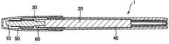
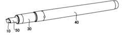
図1は、本発明の第1実施形態における筆記具1の概略縦断面図である。図2は、筆記具1のキャップ60を外した状態の斜視図である。(Configuration of the First Embodiment)
Fig. 1 is a schematic vertical cross-sectional view of a writing instrument 1 according to a first embodiment of the present invention. Fig. 2 is a perspective view of the writing instrument 1 with a
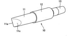
また、図3は、筆記具1のペン先10を示す斜視図であり、図4は、ペン先10の側面図であり、図5は、図4のペン先10のA-A線断面図であり、図6は、図4のペン先10のB-B線断面図である。In addition, FIG. 3 is a perspective view showing the
まず、図1乃至図6に示すように、本実施形態の筆記具1は、前方芯部11と中央芯部12と後方芯部13とを有するペン先10と、ペン先10の後方芯部13に接触して当該後方芯部13にインクを供給するインク吸蔵体20と、を備えている。インク吸蔵体20は、本体筒を構成する前筒30と後筒40とによって収容されている。キャップ60が、前筒30又は後筒40に対して着脱可能となっている。First, as shown in Figures 1 to 6, the writing instrument 1 of this embodiment includes a
図3乃至図6に示すように、本実施形態のペン先10の前方芯部11と中央芯部12と後方芯部13とは、同心の円柱形状を有しているが(詳細には、後述する前方芯部11の前端領域とテーパ部12t、13tとを除く)、前方芯部11は中央芯部12よりも細い。また、後方芯部13についても、中央芯部12よりも細い。例えば、前方芯部11の直径は4.2mmであり、中央芯部12の直径は5.1mmであり、後方芯部13の直径は3.5mmである。As shown in Figures 3 to 6, the
後方芯部13の後方側には、緩やかな傾斜のテーパ部13tが設けられていて、インク吸蔵体20への挿入が容易化されている。また、中央芯部12の後方側には、比較的急峻な傾斜のテーパ部12tが設けられていて、後方芯部13に連続している。例えば、後方芯部13の長さ(テーパ部13tを含む)は7.7mmであり、中央芯部12の長さ(テーパ部12tを含む)は11.8mmである。A gently sloping tapered
前方芯部11の前端は、側面視において上端が下端よりも前方に位置する切出刃状になっており(図4参照)、左右方向にRが設けられる(図5参照)と共に上下方向に傾斜した(図4参照)前端部11aと、当該前端部11aの左右両側に設けられ互いに鋭角(例えば60度)をなす(図5参照)鋭角形成平面部11b、11cと、を有している(鋭角形成平面部11b、11cの延長面の交線は、前端部11aの更に前方に位置して前端部11aと平行に延びる直線である)。例えば、前方芯部11の側面視における上端長さL1(最大長さ)は13.8mmであり、前方芯部11の側面視における下端長さL2(最小長さ)は12.3mmである。前端部11aと鋭角形成平面部11b、11cとは、切削加工によって形成されてもよいし、予め成型加工によって形成されてもよい。The front end of the
また、本実施形態の筆記具1は、図1及び図2に示すように、ペン先10の中央芯部12を保持する一方で、本体筒である前筒30に保持されたペン先保持筒50を備えている。As shown in Figures 1 and 2, the writing instrument 1 of this embodiment also includes a
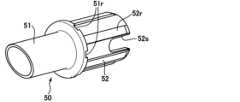
図7は、筆記具1のペン先保持筒50を示す斜視図であり、図8は、図7のペン先保持筒50の断面斜視図であり、図9は、図7のペン先保持筒50の平面図であり、図10は、図9のペン先保持筒50のA-A線断面図である。Figure 7 is a perspective view showing the
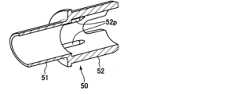
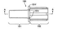
また、図11は、筆記具1のペン先10及びペン先保持筒50を示す斜視図であり、図12は、ペン先10及びペン先保持筒50を示す側面図であり、図13は、図12のペン先10及びペン先保持筒50のA-A線断面図であり、図14は、図12のペン先10及びペン先保持筒50のB-B線断面図であり、図15は、図14のペン先10及びペン先保持筒50のC部拡大図である。In addition, FIG. 11 is a perspective view showing the
図7乃至図15に示すように、ペン先保持筒50は、ペン先10の中央芯部12を保持する保持筒部52と、ペン先10の前方芯部11の前端領域(前端部11aと鋭角形成平面部11b、11cとを含む領域)を除いて当該前方芯部11の周囲に延在する予備筒部51と、を有している。保持筒部52と予備筒部51とは、同心の略円筒形状を有している。As shown in Figures 7 to 15, the
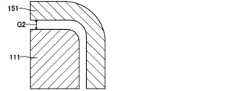
例えば、予備筒部51の側面視における上端長さL3(最大長さ)は10mmであり、予備筒部51の側面視における下端長さL4(最小長さ)は8mmであり、予備筒部51の外面(後述するフランジ部51fを除く)は、直径5.4mmの円筒面であり、予備筒部51の内面は、直径4.6mmの円筒面である。従って、本実施形態では、予備筒部51の内周面とペン先10の前方芯部11の外周面との間の間隔(図15の符号G1)は、0.2mmで一定となっている(図16を用いて後述されるように、筆記時にペン先10に力が加えられると変化する)。また、予備筒部51の内周面又はペン先10の前方芯部11の外周面の少なくとも一方に軸方向の抜き勾配を設けてもよい。これにより、予備筒部51及びペン先10の生産性が向上するだけでなく、前方芯部11の十分な撓みやすさを提供することができる。For example, the upper end length L3 (maximum length) of the
また、予備筒部51の前端も、側面視において上端が下端よりも前方に位置する切出刃状になっており(図10参照)、ペン先10の前方芯部11の前端と予備筒部51の前端とが、側面視において平行となっている(図12参照)。The front end of the
また、保持筒部52は、ペン先10の中央芯部12の前方部を周方向に間隔を開けて4個所で保持するべく、直径5.5mmの円筒面である内周面上の4箇所に保持突起52pが設けられている(図8及び図10参照)。各保持突起52pは、例えば、周方向幅0.6mm、長さ3.6mmであって、軸心からの径方向距離2.4mmの位置まで内方へと突出されている。The holding
また、本実施形態では、予備筒部51の後方端部にフランジ部51fが設けられており、当該フランジ部51fに、凹形状の空気孔51rが設けられている。当該空気孔51rを介して、本体筒内部と本体筒外部とが通気可能となっている。これにより、インク消費に伴って本体筒内部に空気が取り込まれ、適切なインク吐出性能を維持することができる。また、保持筒部52には、前筒30との係合のために径方向外方に突出する縦リブ52rと、ペン先10とペン先保持筒50との組立性を向上させるためのスリット52sと、が設けられている。当該スリット52sを利用することで、ペン先10とペン先保持筒50の軸心に対する回転方向の位置合わせ(前端部11aと予備筒部51の前端とを側面視において平行にすること)を組立機上で容易に行うことができる。In this embodiment, a
そして、図1に示すように、前筒30は、ペン先保持筒50の縦リブ52rを利用して、ペン先保持筒50を保持している。また、保持筒部52の長さは、中央芯部12の長さよりも短く(図11乃至図13参照)、前筒30は、ペン先10の中央芯部12の後方部のテーパ部12tをも保持している。As shown in Figure 1, the
なお、ペン先10は、例えば連続気泡を有する合成樹脂の多孔質体からなるが、インクが流通可能で可撓性を有するものであればよく、具体的には、繊維ペン先、フェルトペン先、毛筆ペン先、軸方向の毛細管通路を有するプラスチックペン先等であってもよい。ペン先10の前方芯部11の変形のしやすさは、例えば、前端部11aの全体を紙面に当接させ且つ前方芯部11の軸心を紙面に対して60度に傾けた状態(図16に類似した状態)から前方芯部11を更に紙面に押し当てた時、押し当て力100gfに対する前端部11aの変位量(紙面に垂直な方向)が0.40~0.48mmの範囲内であることが好適である。また、ペン先保持筒50の予備筒部51は、前方芯部11よりも変形しにくい必要があり、例えば、予備筒部51の前端の上下方向の中央位置での側面角部を紙面に当接させ且つ当該側面を紙面に対して60度に傾けた状態(図16に類似した状態)から予備筒部51を紙面に押し当てた時、押し当て力100gfに対する予備筒部51の変位量(紙面に垂直な方向)が0.02~0.04mmの範囲内であることが好適である。The
また、インク吸蔵体20は、インクを含浸可能な連続気孔を有する部材からなるものであればよく、例えば、繊維束の熱融着加工体、繊維束の樹脂加工体、フェルトの樹脂加工体、フェルトのニードルパンチ加工体、多孔質体(例えば、スポンジ等の合成樹脂の連続気泡体)等が挙げられる。また、インク吸蔵体20は、その外周面に合成樹脂フィルム等よりなる外皮を備える構成でもよい。The
(第1実施形態の作用効果)
以上のような構成の筆記具1は、以下のような作用効果を奏することができる。すなわち、本実施形態の筆記具1によれば、ペン先保持筒50に保持されるペン先10の中央芯部12よりもペン先10の前方芯部11が細いため、ペン先10の中央芯部12に対するペン先10の前方芯部11の十分な撓みやすさを提供することができる。(Functions and Effects of the First Embodiment)
The writing instrument 1 configured as above can achieve the following effects. That is, according to the writing instrument 1 of this embodiment, since the
そして、ペン先10の前方芯部11の前端が側面視において切出刃状になっていて、ペン先10の前方芯部11の側面視における上端長さL1(最大長さ)が13.8mmであって十分長い(7mm以上である)という特徴と相俟って、ペン先10の前方芯部11の前端に加えられる力によってペン先10の前方芯部11が撓む感覚を、ユーザは独特の筆記感として楽しむことができる。The front end of the
一方で、本実施形態の筆記具1によれば、ペン先10の前方芯部11の前端領域を除いて、当該前方芯部11の周囲にペン先保持筒50の予備筒部51が延在しており、ペン先10の前方芯部11に過度の力が加えられた時には当該予備筒部51がペン先10の前方芯部11に当接して当該前方芯部11のそれ以上の変形を抑制する。この状態が図16に図示されている。図16は、筆記具1のペン先10が撓んだ状態を示す概略図である。On the other hand, according to the writing instrument 1 of this embodiment, the
特に本実施形態では、予備筒部51の側面視における上端長さL3(最大長さ)が10mmであって十分長く(5mm以上)、予備筒部51とペン先10の前方芯部11との間の無負荷時の間隔G1が0.2mmで一定である(図15参照)という特徴と相俟って、ペン先10の前方芯部11において元の形状に戻りにくくなるような過度の変形が効果的に抑制され、長寿命を実現できる。In particular, in this embodiment, the length L3 (maximum length) of the top end of the
また、本実施形態の筆記具1によれば、ペン先保持筒50の保持突起52pがペン先10の中央芯部12の前方部を保持しており、本体筒である前筒30がペン先10の中央芯部12のテーパ部12tを保持している。これにより、ペン先10の中央芯部12が軸方向に2箇所で保持されており、ペン先10の中央芯部12のより確実な保持が実現されている。In addition, according to the writing instrument 1 of this embodiment, the holding
また、本実施形態の筆記具1によれば、ペン先10の中央芯部12が円筒形状を有している。これにより、ペン先10に十分な強度を持たせることができ、ペン先10の中央芯部12のより確実な保持が実現されている。In addition, according to the writing instrument 1 of this embodiment, the
また、本実施形態の筆記具1によれば、ペン先保持筒50の保持突起52pが、ペン先10の中央芯部12を周方向に間隔(好適には等間隔)を開けて4個所で保持している。これにより、ペン先10の中央芯部12をバランス良く保持することができ、ペン先10の中央芯部12のより確実な保持が実現されている。In addition, according to the writing instrument 1 of this embodiment, the holding
また、本実施形態の筆記具1によれば、ペン先10に力が加えられていない状態では、予備筒部51とペン先10の前方芯部11との間の間隔G1が一定である。これにより、ペン先10の前方芯部11の過度の変形を抑制する効果を、予備筒部51によって全方位において効果的に提供することができる。また、デザイン(美観)上も優れた形態を提供することができる。In addition, with the writing instrument 1 of this embodiment, when no force is being applied to the
また、本実施形態の筆記具1によれば、予備筒部51の前端も、側面視において上端が下端よりも前方に位置する切出刃状になっており(図10参照)、ペン先10の前方芯部11の前端と予備筒部51の前端とが、側面視において平行となっている(図12参照)。これにより、切出刃状のペン先10の前方芯部11の過度の変形を抑制する効果を、全方位においてより効果的に提供することができる。また、デザイン(美観)上も優れた形態を提供することができる。In addition, according to the writing instrument 1 of this embodiment, the front end of the
(第2実施形態の構成)
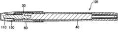
続いて、図17は、本発明の第2実施形態における筆記具101の概略縦断面図である。図18は、筆記具101のキャップ60を外した状態の斜視図である。(Configuration of the second embodiment)
Next, Fig. 17 is a schematic vertical cross-sectional view of a
また、図19は、筆記具101のペン先110を示す斜視図であり、図20は、ペン先110の側面図であり、図21は、図20のペン先110のA-A線断面図であり、図22は、図20のペン先110のB-B線断面図である。In addition, FIG. 19 is a perspective view showing the
まず、図17乃至図22に示すように、本実施形態の筆記具101は、前方芯部111と中央芯部112と後方芯部113とを有するペン先110と、ペン先110の後方芯部113に接触して当該後方芯部113にインクを供給するインク吸蔵体20と、を備えている。第1実施形態と同様、インク吸蔵体20は、本体筒を構成する前筒30と後筒40とによって収容されており、キャップ60が、前筒30又は後筒40に対して着脱可能となっている。First, as shown in Figures 17 to 22, the
図19乃至図22に示すように、本実施形態のペン先110の中央芯部112と後方芯部113とは、同心の円柱形状を有しているが(詳細には、後述するテーパ部112t、113tを除く)、後方芯部113は中央芯部112よりも細い。例えば、中央芯部112の直径は5.1mmであり、後方芯部113の直径は3.5mmである。As shown in Figures 19 to 22, the
また、図19乃至図22に示すように、本実施形態のペン先110の前方芯部111は、後述する前端領域を除いて、角部が丸められた長方形状の断面を有する略四角柱形状を有している(特に図22参照)。中央芯部112の軸心は、前方芯部111の略長方形状の断面の中心(重心)を通るようになっており、当該略長方形状の断面(図22参照)の対角線の長さは、中央芯部112の直径よりも小さくなっている。すなわち、前方芯部111は中央芯部112よりも細い。より詳細には、前方芯部111の略長方形状の断面(図22参照)は、長辺の長さが4.1mmで、短辺の長さが3.2mmである。As shown in Figs. 19 to 22, the
また、第1実施形態と同様、後方芯部113の後方側には、緩やかな傾斜のテーパ部113tが設けられていて、インク吸蔵体20への挿入が容易化されている。また、中央芯部112の後方側には、比較的急峻な傾斜のテーパ部112tが設けられていて、後方芯部113に連続している。例えば、後方芯部113の長さ(テーパ部113tを含む)は7.7mmであり、中央芯部112の長さ(テーパ部112tを含む)は11.8mmである。Also, as in the first embodiment, a gently sloping tapered
また、第1実施形態と略同様、前方芯部111の前端は、側面視において上端が下端よりも前方に位置する切出刃状になっており(図20参照)、左右方向にRが設けられる(図21参照)と共に上下方向に傾斜した(図20参照)前端部111aと、当該前端部111aの左右両側に設けられ互いに鋭角(例えば60度)をなす(図21参照)鋭角形成平面部111b、111cと、を有している(鋭角形成平面部111b、111cの延長面の交線は、前端部111aの更に前方に位置して前端部111aと平行に延びる直線である)。例えば、前方芯部111の側面視における上端長さL11(最大長さ)は13.8mmであり、前方芯部111の側面視における下端長さL12(最小長さ)は12.3mmである。前端部111aと鋭角形成平面部111b、111cとは、切削加工によって形成されてもよいし、予め成型加工によって形成されてもよい。Also, similar to the first embodiment, the front end of the
また、第1実施形態と同様、本実施形態の筆記具101は、図17及び図18に示すように、ペン先110の中央芯部112を保持する一方で、本体筒である前筒30に保持されたペン先保持筒150を備えている。As in the first embodiment, the
図23は、筆記具101のペン先保持筒150を示す斜視図であり、図24は、図23のペン先保持筒150の断面斜視図であり、図25は、図23のペン先保持筒150の平面図であり、図26は、図25のペン先保持筒150のA-A線断面図である。Figure 23 is a perspective view showing the pen
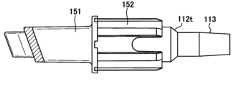
また、図27は、筆記具101のペン先110及びペン先保持筒150を示す斜視図であり、図28は、ペン先110及びペン先保持筒150を示す側面図であり、図29は、図28のペン先110及びペン先保持筒150のA-A線断面図であり、図30は、図28のペン先110及びペン先保持筒150のB-B線断面図であり、図31は、図30のペン先110及びペン先保持筒150のC部拡大図である。In addition, FIG. 27 is a perspective view showing the
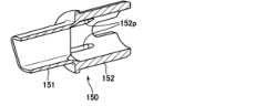
図23乃至図31に示すように、ペン先保持筒150は、ペン先110の中央芯部112を保持する保持筒部152と、ペン先110の前方芯部111の前端領域(前端部111aと鋭角形成平面部111b、111cとを含む領域)を除いて当該前方芯部111の周囲に延在する予備筒部151と、を有している。保持筒部152は、中央芯部112に対応して略円筒形状を有しており、予備筒部151は、前方芯部111に対応して略四角筒形状を有している。As shown in Figures 23 to 31, the
例えば、予備筒部151の側面視における上端長さL13(最大長さ)は10mmであり、予備筒部151の側面視における下端長さL14(最小長さ)は8.3mmであり、予備筒部151(後述するフランジ部151fを除く)の外周面の略長方形状の断面(図30参照)は、長辺の長さが5.3mmで、短辺の長さが4.4mmであり、予備筒部151の内周面の略長方形状の断面(図30参照)は、長辺の長さが4.5mmで、短辺の長さが3.6mmである。従って、本実施形態では、予備筒部151の内周面とペン先110の前方芯部111の外周面との間の間隔(図31の符号G2)は、0.2mmで一定となっている(筆記時にペン先10に力が加えられると変化する:図16参照)。また、予備筒部151の内周面又はペン先110の前方芯部111の外周面の少なくとも一方に軸方向の抜き勾配を設けてもよい。これにより、予備筒部151及びペン先110の生産性が向上するだけでなく、前方芯部111の十分な撓みやすさを提供することができる。For example, the upper end length L13 (maximum length) of the
また、予備筒部151の前端も、側面視において上端が下端よりも前方に位置する切出刃状になっており(図26参照)、ペン先110の前方芯部111の前端と予備筒部151の前端とが、側面視において平行となっている(図28参照)。The front end of the
また、第1実施形態と同様、保持筒部152は、ペン先110の中央芯部112の前方部を周方向に間隔を開けて4個所で保持するべく、直径5.5mmの円筒面である内周面上の4箇所に保持突起152pが設けられている(図24及び図26参照)。各保持突起152pは、例えば、周方向幅0.6mm、長さ3.6mmであって、軸心からの径方向距離2.4mmの位置まで内方へと突出されている。As in the first embodiment, the retaining
また、本実施形態では、予備筒部151の後方端部にフランジ部151fが設けられており、当該フランジ部151fに、凹形状の空気孔151rが設けられている。当該空気孔151rを介して、本体筒内部と本体筒外部とが通気可能となっている。これにより、インク消費に伴って本体筒内部に空気が取り込まれ、適切なインク吐出性能を維持することができる。また、保持筒部152には、前筒30との係合のために径方向外方に突出する縦リブ152rと、ペン先110とペン先保持筒150との組立性を向上させるためのスリット152sと、が設けられている。当該スリット152sを利用することで、ペン先110とペン先保持筒150の軸心に対する回転方向の位置合わせ(前端部111aと予備筒部151の前端とを側面視において平行にすること)を組立機上で容易に行うことができる。In this embodiment, a
そして、図17に示すように、前筒30は、ペン先保持筒150の縦リブ152rを利用して、ペン先保持筒150を保持している。また、保持筒部152の長さは、中央芯部112の長さよりも短く(図27乃至図29参照)、前筒30は、ペン先110の中央芯部112の後方部のテーパ部112tをも保持している。As shown in Figure 17, the
なお、ペン先10の材料について前述された内容は、ペン先110についても適用可能である。The above-mentioned information regarding the material of the
(第2実施形態の作用効果)
以上のような構成の筆記具101は、以下のような作用効果を奏することができる。すなわち、本実施形態の筆記具101によっても、ペン先保持筒150に保持されるペン先110の中央芯部112よりもペン先110の前方芯部111が細いため、ペン先110の中央芯部112に対するペン先110の前方芯部111の十分な撓みやすさを提供することができる。(Functions and Effects of the Second Embodiment)
The
そして、ペン先110の前方芯部111の前端が側面視において切出刃状になっていて、ペン先110の前方芯部111の上端長さL11(最大長さ)が13.8mmであって十分長い(7mm以上である)という特徴と相俟って、ペン先110の前方芯部111の前端に加えられる力によってペン先110の前方芯部111が撓む感覚を、ユーザは独特の筆記感として楽しむことができる。The front end of the
一方で、本実施形態の筆記具101によっても、ペン先110の前方芯部111の前端領域を除いて、当該前方芯部111の周囲にペン先保持筒150の予備筒部151が延在しており、ペン先110の前方芯部111に過度の力が加えられた時には当該予備筒部151がペン先110の前方芯部111に当接して当該前方芯部111のそれ以上の変形を抑制する(第1実施形態について図16を用いて説明されたのと同様である)。On the other hand, even in the
特に本実施形態でも、予備筒部151の最大長さ(上端における長さ)が10mmであって十分長く(5mm以上)、予備筒部151とペン先110の前方芯部111との間の無負荷時の間隔G2が0.2mmで一定である(図31参照)という特徴と相俟って、ペン先110の前方芯部111において元の形状に戻りにくくなるような過度の変形が効果的に抑制され、長寿命を実現できる。In particular, in this embodiment, the maximum length (length at the upper end) of the
また、本実施形態の筆記具101によっても、ペン先保持筒150の保持突起152pがペン先110の中央芯部112の前方部を保持しており、本体筒である前筒30がペン先110の中央芯部112のテーパ部112tを保持している。これにより、ペン先110の中央芯部112が軸方向に2箇所で保持されており、ペン先110の中央芯部112のより確実な保持が実現されている。Also, with the
また、本実施形態の筆記具101によっても、ペン先110の中央芯部112が円筒形状を有している。これにより、ペン先110に十分な強度を持たせることができ、ペン先110の中央芯部112のより確実な保持が実現されている。In addition, the
また、本実施形態の筆記具101によっても、ペン先保持筒150の保持突起152pが、ペン先110の中央芯部112を周方向に間隔(好適には等間隔)を開けて4個所で保持している。これにより、ペン先110の中央芯部112をバランス良く保持することができ、ペン先110の中央芯部112のより確実な保持が実現されている。Also, with the
また、本実施形態の筆記具101によっても、ペン先110に力が加えられていない状態では、予備筒部151とペン先110の前方芯部111との間の間隔G2が一定である。これにより、ペン先110の前方芯部111の過度の変形を抑制する効果を、予備筒部151によって全方位において効果的に提供することができる。また、デザイン(美観)上も優れた形態を提供することができる。In addition, with the
また、本実施形態の筆記具101によっても、予備筒部151の前端が、側面視において上端が下端よりも前方に位置する切出刃状になっており(図26参照)、ペン先110の前方芯部111の前端と予備筒部151の前端とが、側面視において平行となっている(図28参照)。これにより、切出刃状のペン先110の前方芯部111の過度の変形を抑制する効果を、全方位においてより効果的に提供することができる。また、デザイン(美観)上も優れた形態を提供することができる。Also, with the
(ペン先保持筒50、150の色)
以上の各実施形態において、ペン先保持筒50、150は、全体が透明材料または半透明材料で構成されていることが好ましい。この場合、インクの色を視認しやすくなる。また、デザイン(美観)上も優れた形態を提供することができる。(Color of the
In each of the above embodiments, it is preferable that the pen
あるいは、ペン先保持筒50、150の前端近傍領域のみが着色され、残部が透明材料または半透明材料で構成されている態様も有用である。この態様は、筆記対象物(例えば紙面)の色とインクの色とが類似している場合に、筆記具と筆記対象物との相対位置の把握を容易にする効果がある。特に、図32に示すように平行四辺形状の着色領域とすることで、デザイン(美観)上も優れた形態を提供することができる。Alternatively, an embodiment in which only the area near the front end of the
もっとも、少なくとも本件出願の時点では、ペン先保持筒50、150の全体が不透明材料である態様も、本発明の範囲から排除されない。However, at least at the time of filing this application, embodiments in which the entire pen
(角度位置の目印)
また、以上の各実施形態において、本体筒である前筒30及び/またはペン先保持筒50、150に、ペン先10、110の角度位置を示す目印が付されていることが好ましい。この場合、ペン先10、110の角度位置(上端及び下端の向き)を、より容易に把握することができる。当該目印は、視覚的な目印に限定されず、触覚で判別可能な凹凸であってもよい。前軸30を多角形状(三角形状、六角形状等)に構成して、形態全体を目印として機能させてもよい。(Angle position mark)
In each of the above embodiments, it is preferable that the
(部品の一体化)
少なくとも本件出願の時点では、前筒30とペン先保持筒50、150とが一部品として一体化されている態様も、本発明の範囲から排除されない。(Integration of parts)
At least at the time of filing this application, an embodiment in which the
また、少なくとも本件出願の時点では、前筒30と後筒40とが一部品として一体化されている態様も、本発明の範囲から排除されない。In addition, at least at the time of filing this application, the scope of the present invention does not exclude an embodiment in which the
1、101 筆記具
10、110 ペン先
11、111 前方芯部
11a、111a 前端部
11b、111b 鋭角形成平面部
11c、111c 鋭角形成平面部
12、112 中央芯部
12t、112t テーパ部
13、113 後方芯部
13t、113t テーパ部
20 インク吸蔵体
30 前筒(本体筒)
40 後筒(本体筒)
50、150 ペン先保持筒
51、151 予備筒部
51f、151f フランジ部
51r、151r 空気孔
52、152 保持筒部
52p、152p 保持突起
52s、152s スリット
52r、152r 縦リブ
60 キャップ
G1、G2 間隔
L1、L11 前方芯部の側面視における上端長さ
L2、L12 前方芯部の側面視における下端長さ
L3、L13 予備筒部の側面視における上端長さ
L4、L14 予備筒部の側面視における下端長さ
1, 101 Writing implement 10, 110
40 Rear tube (main body tube)
50, 150 Pen
Claims (11)
Translated fromJapanese前記ペン先の前記後方芯部に接触して当該後方芯部にインクを供給するインク吸蔵体と
、
前記インク吸蔵体を収容する本体筒と、
前記ペン先の前記中央芯部を保持し、前記本体筒に保持されるペン先保持筒と、
を備え、
前記ペン先の前記前方芯部は、前記ペン先の前記中央芯部よりも細く、
前記ペン先の前記後方芯部も、前記ペン先の前記中央芯部よりも細く、
前記ペン先の前記前方芯部の前端は、側面視において上端が下端よりも前方に位置する
切出刃状になっており、
前記ペン先保持筒は、前記ペン先の前記中央芯部の前方部を保持しており、
前記本体筒は、前記ペン先の前記中央芯部の後方部を保持しており、
前記ペン先の前記中央芯部は、円筒形状を有しており、
前記ペン先保持筒は、前記ペン先の前記中央芯部を周方向に間隔を開けて複数個所で保持している
ことを特徴とする筆記具。 a pen tip having a front core, a central core, and a rear core;
an ink occlusion body that contacts the rear core portion of the pen tip and supplies ink to the rear core portion;
a main body tube that houses the ink occlusion body;
a pen tip holding tube that holds the central core portion of the pen tip and is held by the main body tube;
Equipped with
The front core of the pen tip is thinner than the central core of the pen tip,
The rear core of the pen tip is also thinner than the central core of the pen tip,
The front end of the front core of the pen tip is formed in a cutting blade shape such that an upper end is located forward of a lower end in a side view,
the pen tip holding tube holds a front portion of the central core of the pen tip,
The main body tube holds a rear portion of the central core of the pen tip,
The central core of the pen tip has a cylindrical shape,
The pen tip holding tube holds the central core of the pen tip at a plurality of points spaced apart in the circumferential direction.
A writing instrument characterized by:
ことを特徴とする請求項1に記載の筆記具。The writing instrument according to claim1 , characterized in thatthe pen tip holding tube is provided with a vertical rib protruding radially outward .
囲に延在する予備筒部を有しており、
前記予備筒部と前記ペン先の前記前方芯部との間の間隔は、略一定である
ことを特徴とする請求項1または2に記載の筆記具。The pen tip holding tube is configured to hold the pen tip around the front core portion except for the front end region of the front core portion.
a spare cylinder portion extending around the
The writing instrument according to claim 1or 2 , characterized in thatthe distance between the auxiliary tube portion and the front core portion of the pen tip is approximately constant.
前記予備筒部は、円筒形状を有している
ことを特徴とする請求項3に記載の筆記具。The front core of the pen tip has a cylindrical shape except for the front end region,
The writing instrument according to claim3, characterized in that the auxiliary cylinder portion has a cylindrical shape .
前記予備筒部は、略四角筒形状を有している
ことを特徴とする請求項3に記載の筆記具。The front core portion of the pen tip has a generally rectangular prism shape except for the front end region,
The writing instrument according to claim3 , characterized in thatthe auxiliary tube portion has a substantially rectangular tube shape .
前記ペン先の前記前方芯部の前記前端と前記予備筒部の前記前端とが、側面視において平行となっている
ことを特徴とする請求項4または5に記載の筆記具。The front end of the auxiliary tube portion is also formed in a cutting blade shape with its upper end positioned forward of its lower end in side view,
The writing instrument according to claim4 or5 , characterizedin that the front end of the front core part of the pen tip and the front end of the spare barrel part are parallel in a side view.
左右方向にRが設けられると共に上下方向に傾斜した前端部と、
当該前端部の左右両側に設けられ互いに鋭角をなす鋭角形成平面部と、
を有している
ことを特徴とする請求項6に記載の筆記具。The front end of the front core of the pen tip is
A front end portion having a curved edge in the left-right direction and an inclined edge in the up-down direction;
acute angle forming flat surfaces provided on both the left and right sides of the front end portion and forming an acute angle with each other;
The writing instrument according to claim6 , furthercomprising :
前記フランジ部に、凹形状の空気孔が設けられている
ことを特徴とする請求項6または7に記載の筆記具。A flange portion is provided at a rear end portion of the auxiliary cylindrical portion,
The writing instrument according to claim6 or7 , characterized in thatthe flange portion is provided with a concave air hole .
ことを特徴とする請求項6乃至8のいずれかに記載の筆記具。The writing instrument according to any one of claims6 to8 , characterized in thata tapered portion is provided on the rear side of the rear core of the pen tip .
ことを特徴とする請求項1乃至9のいずれかに記載の筆記具。The writing instrument according to any one of claims 1 to9 , characterized in thatat least a portion of the pen tip holding tube is made of a transparent or translucent material .
ことを特徴とする請求項1乃至10のいずれかに記載の筆記具。The writing instrument according to any one of claims 1 to10 , characterizedin that the main body tube and/or the pen tip holding tube are provided with a mark indicating the angular position of the pen tip.
Priority Applications (1)
| Application Number | Priority Date | Filing Date | Title |
|---|---|---|---|
| JP2022188913AJP7538843B2 (en) | 2018-07-18 | 2022-11-28 | Writing implements |
Applications Claiming Priority (2)
| Application Number | Priority Date | Filing Date | Title |
|---|---|---|---|
| JP2018134808AJP7186533B2 (en) | 2018-07-18 | 2018-07-18 | writing instrument |
| JP2022188913AJP7538843B2 (en) | 2018-07-18 | 2022-11-28 | Writing implements |
Related Parent Applications (1)
| Application Number | Title | Priority Date | Filing Date |
|---|---|---|---|
| JP2018134808ADivisionJP7186533B2 (en) | 2018-07-18 | 2018-07-18 | writing instrument |
Publications (2)
| Publication Number | Publication Date |
|---|---|
| JP2023011032A JP2023011032A (en) | 2023-01-20 |
| JP7538843B2true JP7538843B2 (en) | 2024-08-22 |
Family
ID=69170589
Family Applications (2)
| Application Number | Title | Priority Date | Filing Date |
|---|---|---|---|
| JP2018134808AActiveJP7186533B2 (en) | 2018-07-18 | 2018-07-18 | writing instrument |
| JP2022188913AActiveJP7538843B2 (en) | 2018-07-18 | 2022-11-28 | Writing implements |
Family Applications Before (1)
| Application Number | Title | Priority Date | Filing Date |
|---|---|---|---|
| JP2018134808AActiveJP7186533B2 (en) | 2018-07-18 | 2018-07-18 | writing instrument |
Country Status (2)
| Country | Link |
|---|---|
| JP (2) | JP7186533B2 (en) |
| CN (1) | CN210881415U (en) |
Families Citing this family (1)
| Publication number | Priority date | Publication date | Assignee | Title |
|---|---|---|---|---|
| WO2025063293A1 (en)* | 2023-09-22 | 2025-03-27 | 株式会社パイロットコーポレーション | Writing implement |
Citations (3)
| Publication number | Priority date | Publication date | Assignee | Title |
|---|---|---|---|---|
| JP2010247349A (en) | 2009-04-10 | 2010-11-04 | Mitsubishi Pencil Co Ltd | Marking pen |
| JP2011255638A (en) | 2010-06-11 | 2011-12-22 | Tsukasa Felt Shoji Kk | Writing body |
| JP2017013464A (en) | 2015-07-06 | 2017-01-19 | 司フエルト商事株式会社 | Tip body and method for producing the same |
Family Cites Families (4)
| Publication number | Priority date | Publication date | Assignee | Title |
|---|---|---|---|---|
| JPS49147024U (en)* | 1973-04-20 | 1974-12-19 | ||
| JPH09240191A (en)* | 1996-03-06 | 1997-09-16 | Teiboo Kk | Structure of pen point |
| JP2841292B2 (en)* | 1997-03-03 | 1998-12-24 | 郁夫 大澤 | Pen with ruler guide |
| JP3083060U (en) | 2001-06-29 | 2002-01-18 | 興和化学産業株式会社 | Pen-type object eraser and pen tip member |
- 2018
- 2018-07-18JPJP2018134808Apatent/JP7186533B2/enactiveActive
- 2019
- 2019-07-15CNCN201921102096.7Upatent/CN210881415U/enactiveActive
- 2022
- 2022-11-28JPJP2022188913Apatent/JP7538843B2/enactiveActive
Patent Citations (3)
| Publication number | Priority date | Publication date | Assignee | Title |
|---|---|---|---|---|
| JP2010247349A (en) | 2009-04-10 | 2010-11-04 | Mitsubishi Pencil Co Ltd | Marking pen |
| JP2011255638A (en) | 2010-06-11 | 2011-12-22 | Tsukasa Felt Shoji Kk | Writing body |
| JP2017013464A (en) | 2015-07-06 | 2017-01-19 | 司フエルト商事株式会社 | Tip body and method for producing the same |
Also Published As
| Publication number | Publication date |
|---|---|
| JP2023011032A (en) | 2023-01-20 |
| JP2020011437A (en) | 2020-01-23 |
| JP7186533B2 (en) | 2022-12-09 |
| CN210881415U (en) | 2020-06-30 |
Similar Documents
| Publication | Publication Date | Title |
|---|---|---|
| JP7275359B2 (en) | writing instrument | |
| US20090257811A1 (en) | Multiple nib writing instrument | |
| JP5366979B2 (en) | pencil | |
| JP7538843B2 (en) | Writing implements | |
| JP6828305B2 (en) | Writing implements | |
| JP6143429B2 (en) | Writing instrument | |
| JP6915962B2 (en) | Stationery | |
| JP7492071B2 (en) | Manufacturing method for writing implement parts | |
| WO2015087852A1 (en) | Ballpoint pen | |
| JP2011126215A (en) | Marking pen | |
| JP7184955B2 (en) | marking pen | |
| JP2841292B2 (en) | Pen with ruler guide | |
| WO2008069776A1 (en) | Multi-tip writing device | |
| CN213798965U (en) | Writing tool | |
| JP4155390B2 (en) | Writing instrument | |
| JP7080077B2 (en) | Stationery | |
| JP2001310583A (en) | Writing utensil | |
| JP7743438B2 (en) | writing implements | |
| JP3247983U (en) | Ruler and writing set | |
| JP3252665U (en) | writing implements | |
| JP4218497B2 (en) | Writing instrument | |
| JP4848066B2 (en) | Writing instrument | |
| JP2005219472A (en) | Composite writing instrument | |
| JP3160448U (en) | Two-color ballpoint pen | |
| JP2025050412A (en) | Writing instrument |
Legal Events
| Date | Code | Title | Description |
|---|---|---|---|
| A521 | Request for written amendment filed | Free format text:JAPANESE INTERMEDIATE CODE: A523 Effective date:20221221 | |
| A621 | Written request for application examination | Free format text:JAPANESE INTERMEDIATE CODE: A621 Effective date:20221221 | |
| A131 | Notification of reasons for refusal | Free format text:JAPANESE INTERMEDIATE CODE: A131 Effective date:20240206 | |
| A601 | Written request for extension of time | Free format text:JAPANESE INTERMEDIATE CODE: A601 Effective date:20240403 | |
| A521 | Request for written amendment filed | Free format text:JAPANESE INTERMEDIATE CODE: A523 Effective date:20240520 | |
| TRDD | Decision of grant or rejection written | ||
| A01 | Written decision to grant a patent or to grant a registration (utility model) | Free format text:JAPANESE INTERMEDIATE CODE: A01 Effective date:20240723 | |
| A61 | First payment of annual fees (during grant procedure) | Free format text:JAPANESE INTERMEDIATE CODE: A61 Effective date:20240809 | |
| R150 | Certificate of patent or registration of utility model | Ref document number:7538843 Country of ref document:JP Free format text:JAPANESE INTERMEDIATE CODE: R150 |