JP7537391B2 - Object detection device - Google Patents
Object detection deviceDownload PDFInfo
- Publication number
- JP7537391B2 JP7537391B2JP2021119413AJP2021119413AJP7537391B2JP 7537391 B2JP7537391 B2JP 7537391B2JP 2021119413 AJP2021119413 AJP 2021119413AJP 2021119413 AJP2021119413 AJP 2021119413AJP 7537391 B2JP7537391 B2JP 7537391B2
- Authority
- JP
- Japan
- Prior art keywords
- blind spot
- closed
- sensor
- vehicle
- closed blind
- Prior art date
- Legal status (The legal status is an assumption and is not a legal conclusion. Google has not performed a legal analysis and makes no representation as to the accuracy of the status listed.)
- Active
Links
Images


Classifications
- G—PHYSICS
- G01—MEASURING; TESTING
- G01S—RADIO DIRECTION-FINDING; RADIO NAVIGATION; DETERMINING DISTANCE OR VELOCITY BY USE OF RADIO WAVES; LOCATING OR PRESENCE-DETECTING BY USE OF THE REFLECTION OR RERADIATION OF RADIO WAVES; ANALOGOUS ARRANGEMENTS USING OTHER WAVES
- G01S13/00—Systems using the reflection or reradiation of radio waves, e.g. radar systems; Analogous systems using reflection or reradiation of waves whose nature or wavelength is irrelevant or unspecified
- G01S13/88—Radar or analogous systems specially adapted for specific applications
- G01S13/93—Radar or analogous systems specially adapted for specific applications for anti-collision purposes
- G01S13/931—Radar or analogous systems specially adapted for specific applications for anti-collision purposes of land vehicles
- B—PERFORMING OPERATIONS; TRANSPORTING
- B60—VEHICLES IN GENERAL
- B60W—CONJOINT CONTROL OF VEHICLE SUB-UNITS OF DIFFERENT TYPE OR DIFFERENT FUNCTION; CONTROL SYSTEMS SPECIALLY ADAPTED FOR HYBRID VEHICLES; ROAD VEHICLE DRIVE CONTROL SYSTEMS FOR PURPOSES NOT RELATED TO THE CONTROL OF A PARTICULAR SUB-UNIT
- B60W30/00—Purposes of road vehicle drive control systems not related to the control of a particular sub-unit, e.g. of systems using conjoint control of vehicle sub-units
- B60W30/08—Active safety systems predicting or avoiding probable or impending collision or attempting to minimise its consequences
- B—PERFORMING OPERATIONS; TRANSPORTING
- B60—VEHICLES IN GENERAL
- B60W—CONJOINT CONTROL OF VEHICLE SUB-UNITS OF DIFFERENT TYPE OR DIFFERENT FUNCTION; CONTROL SYSTEMS SPECIALLY ADAPTED FOR HYBRID VEHICLES; ROAD VEHICLE DRIVE CONTROL SYSTEMS FOR PURPOSES NOT RELATED TO THE CONTROL OF A PARTICULAR SUB-UNIT
- B60W40/00—Estimation or calculation of non-directly measurable driving parameters for road vehicle drive control systems not related to the control of a particular sub unit, e.g. by using mathematical models
- B60W40/02—Estimation or calculation of non-directly measurable driving parameters for road vehicle drive control systems not related to the control of a particular sub unit, e.g. by using mathematical models related to ambient conditions
- B60W40/04—Traffic conditions
- B—PERFORMING OPERATIONS; TRANSPORTING
- B60—VEHICLES IN GENERAL
- B60W—CONJOINT CONTROL OF VEHICLE SUB-UNITS OF DIFFERENT TYPE OR DIFFERENT FUNCTION; CONTROL SYSTEMS SPECIALLY ADAPTED FOR HYBRID VEHICLES; ROAD VEHICLE DRIVE CONTROL SYSTEMS FOR PURPOSES NOT RELATED TO THE CONTROL OF A PARTICULAR SUB-UNIT
- B60W50/00—Details of control systems for road vehicle drive control not related to the control of a particular sub-unit, e.g. process diagnostic or vehicle driver interfaces
- B60W50/08—Interaction between the driver and the control system
- B60W50/14—Means for informing the driver, warning the driver or prompting a driver intervention
- B—PERFORMING OPERATIONS; TRANSPORTING
- B60—VEHICLES IN GENERAL
- B60W—CONJOINT CONTROL OF VEHICLE SUB-UNITS OF DIFFERENT TYPE OR DIFFERENT FUNCTION; CONTROL SYSTEMS SPECIALLY ADAPTED FOR HYBRID VEHICLES; ROAD VEHICLE DRIVE CONTROL SYSTEMS FOR PURPOSES NOT RELATED TO THE CONTROL OF A PARTICULAR SUB-UNIT
- B60W60/00—Drive control systems specially adapted for autonomous road vehicles
- B60W60/001—Planning or execution of driving tasks
- B—PERFORMING OPERATIONS; TRANSPORTING
- B60—VEHICLES IN GENERAL
- B60W—CONJOINT CONTROL OF VEHICLE SUB-UNITS OF DIFFERENT TYPE OR DIFFERENT FUNCTION; CONTROL SYSTEMS SPECIALLY ADAPTED FOR HYBRID VEHICLES; ROAD VEHICLE DRIVE CONTROL SYSTEMS FOR PURPOSES NOT RELATED TO THE CONTROL OF A PARTICULAR SUB-UNIT
- B60W2420/00—Indexing codes relating to the type of sensors based on the principle of their operation
- B60W2420/40—Photo, light or radio wave sensitive means, e.g. infrared sensors
- B60W2420/403—Image sensing, e.g. optical camera
- B—PERFORMING OPERATIONS; TRANSPORTING
- B60—VEHICLES IN GENERAL
- B60W—CONJOINT CONTROL OF VEHICLE SUB-UNITS OF DIFFERENT TYPE OR DIFFERENT FUNCTION; CONTROL SYSTEMS SPECIALLY ADAPTED FOR HYBRID VEHICLES; ROAD VEHICLE DRIVE CONTROL SYSTEMS FOR PURPOSES NOT RELATED TO THE CONTROL OF A PARTICULAR SUB-UNIT
- B60W2420/00—Indexing codes relating to the type of sensors based on the principle of their operation
- B60W2420/40—Photo, light or radio wave sensitive means, e.g. infrared sensors
- B60W2420/408—Radar; Laser, e.g. lidar
- G—PHYSICS
- G01—MEASURING; TESTING
- G01S—RADIO DIRECTION-FINDING; RADIO NAVIGATION; DETERMINING DISTANCE OR VELOCITY BY USE OF RADIO WAVES; LOCATING OR PRESENCE-DETECTING BY USE OF THE REFLECTION OR RERADIATION OF RADIO WAVES; ANALOGOUS ARRANGEMENTS USING OTHER WAVES
- G01S13/00—Systems using the reflection or reradiation of radio waves, e.g. radar systems; Analogous systems using reflection or reradiation of waves whose nature or wavelength is irrelevant or unspecified
- G01S13/88—Radar or analogous systems specially adapted for specific applications
- G01S13/93—Radar or analogous systems specially adapted for specific applications for anti-collision purposes
- G01S13/931—Radar or analogous systems specially adapted for specific applications for anti-collision purposes of land vehicles
- G01S2013/9315—Monitoring blind spots
Landscapes
- Engineering & Computer Science (AREA)
- Automation & Control Theory (AREA)
- Mechanical Engineering (AREA)
- Transportation (AREA)
- Physics & Mathematics (AREA)
- Radar, Positioning & Navigation (AREA)
- Remote Sensing (AREA)
- Human Computer Interaction (AREA)
- Mathematical Physics (AREA)
- General Physics & Mathematics (AREA)
- Computer Networks & Wireless Communication (AREA)
- Electromagnetism (AREA)
- Traffic Control Systems (AREA)
Description
Translated fromJapanese本開示は、物体検出装置に関する。This disclosure relates to an object detection device.
特許文献1は、物体検出装置を開示する。この装置は、センサの出力に基づいて車両の周辺に存在する障害物を特定するとともに、センサの検出範囲に含まれない死角領域を特定する。次に、この装置は、特定した死角領域のうち、障害物が存在する可能性のある領域と重複する領域を、障害物が存在しうる危険死角領域とする。
特許文献1に記載の装置にあっては、障害物の存在を検出し、その障害物の移動位置を適切に推測できなければ、危険死角領域を判定できない。例えば、障害物がセンサの死角に入った場合には、死角領域は危険死角領域と判定される。このとき、障害物の移動位置を適切に推測できなければ、障害物がセンサの死角に入った状態を維持しながら遠方に過ぎ去った場合であっても、装置は死角領域を危険死角領域と捉え続けるおそれがある。本開示は、死角に存在する障害物の移動位置の推定を行わずに死角領域における物体の有無を判定することができる技術を提供する。In the device described in
本開示の一側面に係る物体検出装置は、移動体に搭載されたセンサの死角に物体が存在するか否かを判定する装置である。この装置は、センサの検出結果に基づいて、センサの閉じた死角への物体の出入状況を取得する取得部と、出入状況に基づいて、閉じた死角における物体の有無を判定する判定部とを備える。An object detection device according to one aspect of the present disclosure is a device that determines whether or not an object is present in a blind spot of a sensor mounted on a moving object. This device includes an acquisition unit that acquires the entry and exit status of an object into the closed blind spot of the sensor based on the detection result of the sensor, and a determination unit that determines the presence or absence of an object in the closed blind spot based on the entry and exit status.
この物体検出装置によれば、センサの閉じた死角への物体の出入状況が取得部によって取得される。そして、閉じた死角における物体の有無が、判定部によって出入状況に基づいて判定される。センサの閉じた死角とは、例えばセンサの視野内を経由しなければ進入できない死角である。つまり、センサの閉じた死角への物体の出入りがセンサによって検出された場合、センサの閉じた死角に存在する物体の個数は増減することになる。この物体検出装置は、センサの閉じた死角への物体の出入状況を把握することにより、死角に存在する障害物の移動位置の推定を行わずに死角領域における物体の有無を判定することができる。According to this object detection device, the acquisition unit acquires the entry and exit status of objects in the closed blind spot of the sensor. Then, the determination unit determines the presence or absence of an object in the closed blind spot based on the entry and exit status. The closed blind spot of the sensor is, for example, a blind spot that cannot be entered without passing through the field of view of the sensor. In other words, when the sensor detects an object entering or exiting the closed blind spot of the sensor, the number of objects present in the closed blind spot of the sensor increases or decreases. By grasping the entry and exit status of objects in the closed blind spot of the sensor, this object detection device can determine the presence or absence of an object in the blind spot area without estimating the moving position of an obstacle present in the blind spot.
一実施形態においては、センサの閉じた死角は、センサの死角のうち、センサに対して固定的に存在する死角であって、センサの観測可能な距離よりも遠方にいる物体がセンサの視野内を経由しなければ進入できない死角としてもよい。この場合、物体検出装置は、センサの閉じた死角に存在する物体の個数の増減を確実に把握することができる。In one embodiment, the closed blind spot of the sensor may be a blind spot that is fixed relative to the sensor and that an object that is farther away than the observable distance of the sensor cannot enter without passing through the field of view of the sensor. In this case, the object detection device can reliably grasp the increase or decrease in the number of objects that exist in the closed blind spot of the sensor.
一実施形態においては、判定部は、閉じた死角に物体が存在しないことを示す情報を取得し、情報を取得した後において物体の閉じた死角への進入が検出されない場合には、閉じた死角に物体は存在しないと判定してもよい。このように構成することで、物体検出装置は、センサの閉じた死角に存在する物体の個数が0であることを予め把握し、センサの閉じた死角に存在する物体の個数が増加していないことを検出することにより、死角において物体が存在しないことを判定することができる。In one embodiment, the determination unit may obtain information indicating that no object is present in the closed blind spot, and may determine that no object is present in the closed blind spot if an object is not detected entering the closed blind spot after obtaining the information. By configuring in this manner, the object detection device can determine that no object is present in the blind spot by knowing in advance that the number of objects present in the closed blind spot of the sensor is zero and detecting that the number of objects present in the closed blind spot of the sensor has not increased.
一実施形態においては、判定部は、閉じた死角に存在する物体の個数を予め取得し、予め取得された物体の個数と、閉じた死角へ進入した物体の個数と、閉じた死角から退出した物体の個数とに基づいて物体の有無を判定してもよい。このように構成することで、物体検出装置は、センサの閉じた死角に存在する物体の個数を予め把握し、センサの閉じた死角に存在する物体の個数の増減を検出することにより、死角における物体の有無を判定することができる。In one embodiment, the determination unit may obtain in advance the number of objects present in the closed blind spot, and determine the presence or absence of an object based on the number of objects obtained in advance, the number of objects that have entered the closed blind spot, and the number of objects that have left the closed blind spot. By configuring in this manner, the object detection device can determine the presence or absence of an object in the blind spot by knowing in advance the number of objects present in the closed blind spot of the sensor and detecting an increase or decrease in the number of objects present in the closed blind spot of the sensor.
一実施形態においては、閉じた死角から移動体へ乗り込む人数及び移動体から閉じた死角へ降りる人数を取得する人数取得部を備え、判定部は、乗り込む人数及び降りる人数に基づいて閉じた死角における物体の有無を判定してもよい。このように構成することで、物体検出装置は、センサの閉じた死角に存在する人数を人数取得部によって予め把握し、センサの閉じた死角に存在する人数の増減を検出することにより、死角における物体の有無を判定することができる。In one embodiment, a number acquisition unit is provided that acquires the number of people getting on to a moving object from a closed blind spot and the number of people getting off from a moving object into the closed blind spot, and the determination unit may determine the presence or absence of an object in the closed blind spot based on the number of people getting on and getting off. By configuring in this way, the object detection device can determine the presence or absence of an object in the blind spot by detecting an increase or decrease in the number of people in the closed blind spot of the sensor by grasping in advance the number of people present in the sensor's closed blind spot using the number acquisition unit.
一実施形態においては、移動体が停止しており、かつ、閉じた死角に物体が存在しないことを示す情報を取得できていない場合には、物体が存在しないことを示す情報を取得できていない閉じた死角に対応する位置がセンサの視野内に入るように移動体を移動させる移動体制御部を備えてもよい。このように構成することで、物体検出装置は、閉じた死角に物体が存在しないことを示す情報を能動的に把握することができる。In one embodiment, a mobile object control unit may be provided that, when the mobile object is stopped and information indicating that no object is present in the closed blind spot cannot be obtained, moves the mobile object so that a position corresponding to the closed blind spot where information indicating that no object is present cannot be obtained is within the field of view of the sensor. By configuring in this manner, the object detection device can actively obtain information indicating that no object is present in the closed blind spot.
一実施形態においては、センサの閉じた死角に関する情報を運転者に報知させる報知制御部を備えてもよい。このように構成することで、物体検出装置は、センサの閉じた死角に関する情報を運転者に報知することができる。In one embodiment, a notification control unit may be provided that notifies the driver of information regarding the blind spot that is closed by the sensor. By configuring in this manner, the object detection device can notify the driver of information regarding the blind spot that is closed by the sensor.
一実施形態においては、センサの閉じた死角に関する情報を、車外のセンサの閉じた死角に向けて報知させる報知制御部を備えてもよい。このように構成することで、物体検出装置は、センサの閉じた死角に関する情報を、閉じた死角に存在する物体に対して報知することができる。In one embodiment, a notification control unit may be provided that notifies information about the closed blind spot of the sensor to the closed blind spot of the sensor outside the vehicle. By configuring in this manner, the object detection device can notify information about the closed blind spot of the sensor to an object present in the closed blind spot.
本開示によれば、死角に存在する障害物の移動位置の推定を行わずに死角領域における物体の有無を判定することができる。According to the present disclosure, it is possible to determine the presence or absence of an object in a blind spot area without estimating the moving position of an obstacle in the blind spot.
以下、図面を参照して、例示的な実施形態について説明する。なお、以下の説明において、同一又は相当要素には同一符号を付し、重複する説明は繰り返さない。Below, an exemplary embodiment will be described with reference to the drawings. In the following description, the same or equivalent elements will be given the same reference numerals, and duplicate descriptions will not be repeated.
(車両及び走行制御装置の構成)
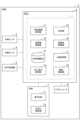
図1は、実施形態に係る物体検出装置を含む車両の一例の機能ブロック図である。図1に示されるように、物体検出装置1は、バス、タクシー、又は一般的な乗用車などの車両2(移動体の一例)に搭載される。車両2は、運転者の操作により走行してもよいし、自動運転によって走行してもよいし、遠隔操作によって走行してもよい。(Configuration of vehicle and driving control device)
Fig. 1 is a functional block diagram of an example of a vehicle including an object detection device according to an embodiment. As shown in Fig. 1, the
車両2は、外部センサ3、内部センサ4、GPS(Global PositioningSystem)受信機5、ECU(Electronic Control Unit)6、HMI(Human Machine Interface)7、及び、アクチュエータ8を備える。The
外部センサ3は、車両2の外部環境の情報を検出する検出器である。外部環境とは、車両2の周辺の物体の位置、又は物体の状況などである。外部センサ3の検出結果には、車両2が走行する車道の前方の物体の位置、形状、色などが含まれる。物体には、車両、歩行者、信号機、路面ペイントなどが含まれる。外部センサ3は、一例としてカメラである。The
カメラは、車両2の外部状況を撮像する撮像機器である。カメラは、一例として車両2のフロントガラスの裏側に設けられる。カメラは、車両2の外部状況に関する撮像情報を取得する。カメラは、単眼カメラであってもよく、ステレオカメラであってもよい。ステレオカメラは、両眼視差を再現するように配置された二つの撮像部を有する。ステレオカメラの撮像情報には、奥行き方向の情報も含まれる。The camera is an imaging device that captures images of the external situation of
外部センサ3は、カメラに限定されず、レーダセンサなどであってもよい。レーダセンサは、電波(例えばミリ波)又は光を利用して車両2の周辺の物体を検出する検出器である。レーダセンサには、例えば、ミリ波レーダ又はライダー(LIDAR:Laser Imaging Detection and Ranging)が含まれる。レーダセンサは、電波又は光を車両2の周辺に送信し、物体で反射された電波又は光を受信することで物体を検出する。The
内部センサ4は、車両2の走行状態を検出する検出器である。内部センサ4は、舵角センサ、車速センサ、加速度センサ及びヨーレートセンサを含んでもよい。舵角センサは、車両2の操舵軸の回転量を検出する検出器である。車速センサは、車両2の速度を検出する検出器である。車速センサとしては、例えば、車両2の車輪又は車輪と一体に回転するドライブシャフトなどに対して設けられ、車輪の回転速度を検出する車輪速センサが用いられる。加速度センサは、車両2の加速度を検出する検出器である。加速度センサは、車両2の前後方向の加速度を検出する前後加速度センサと、車両2の加速度を検出する横加速度センサとを含んでもよい。ヨーレートセンサは、車両2の重心の鉛直軸周りのヨーレート(回転角速度)を検出する検出器である。ヨーレートセンサとしては、例えばジャイロセンサを用いることができる。The
GPS受信機5は、三個以上のGPS衛星から信号を受信することにより、車両2の位置(例えば車両2の緯度及び経度)を測定する。ECU6は、外部センサ3の検出結果と地図情報を用いて、車両2の位置情報を取得してもよい。The
ECU6は、車両2の動作を制御する。ECU6は、CPU(CentralProcessing Unit)、ROM(Read Only Memory)、RAM(Random Access Memory)、CAN(Controller AreaNetwork)通信回路などを有する電子制御ユニットである。ECU6は、例えばCAN通信回路を用いて通信するネットワークに接続され、上述した車両2の構成要素と通信可能に接続される。ECU6は、例えば、CPUが出力する信号に基づいて、CAN通信回路を動作させてデータを入出力し、データをRAMに記憶し、ROMに記憶されているプログラムをRAMにロードし、RAMにロードされたプログラムを実行することで、後述する機能を実現する。ECU6は、複数の電子制御ユニットから構成されてもよい。The ECU 6 controls the operation of the
HMI7は、車両2の乗員(運転者含む)又は車外に存在する人と、ECU6によって実現されるシステムとのインターフェイスである。HMI7は、車内HMI71及び外向け報知部72を含む。車内HMI71は、車両2の乗員のためのインターフェイスであり、一例として、情報を表示可能であり、かつ、乗員の操作入力を受け付け可能なタッチディスプレイなどを含む。外向け報知部72は、歩行者などの車外に存在する人のためのインターフェイスであり、一例として、車両2の外観に設けられたディスプレイ又は路面投影機などである。HMI7は、画像又は映像を表示するインターフェイスに限定されず、音声を出力するインターフェイスであってもよい。The
アクチュエータ8は、車両2の走行制御を実行する装置である。アクチュエータ8は、エンジンアクチュエータ、ブレーキアクチュエータ、及び操舵アクチュエータを少なくとも含む。エンジンアクチュエータは、運転操作又はECU6の制御信号に応じてエンジンに対する空気の供給量を変更(例えばスロットル開度を変更)することで、車両2の駆動力を制御する。なお、エンジンアクチュエータは、車両2がハイブリッド車又は電気自動車である場合には、動力源としてのモータの駆動力を制御する。The
ブレーキアクチュエータは、ECU6からの制御信号に応じてブレーキシステムを制御し、車両2の車輪へ付与する制動力を制御する。ブレーキシステムとしては、例えば、液圧ブレーキシステムを用いることができる。なお、ブレーキアクチュエータは、車両2が回生ブレーキシステムを備えている場合、液圧ブレーキシステム及び回生ブレーキシステムの両方を制御してもよい。操舵アクチュエータは、電動パワーステアリングシステムのうち操舵トルクを制御するアシストモータの駆動を、ECU6からの制御信号に応じて制御する。これにより、操舵アクチュエータは、車両2の操舵トルクを制御する。The brake actuator controls the brake system in response to a control signal from the ECU 6, and controls the braking force applied to the wheels of the
(死角の概要)
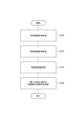
ECU6の各機能を説明する前に、ECU6によって判定される対象である死角について説明する。図2は、死角の定義を説明するツリー図である。図2に示されるように、死角9は、動的死角91と静的死角92に区分される。静的死角92は、開いた死角93及び閉じた死角94に区分される。動的死角91は、開いた死角93に区分される。ECU6によって判定される対象は、死角9に含まれる閉じた死角94である。(Blind Spot Overview)
Before describing each function of the ECU 6, the blind spots that are the object of judgment by the ECU 6 will be described. FIG. 2 is a tree diagram for explaining the definition of the blind spots. As shown in FIG. 2, the
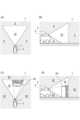
最初に、死角9について説明する。図3の(A)は視野内及び死角を説明する上面図、図3の(B)は視野内及び死角を説明する側面図である。図3の(A)及び図3の(B)に示される例では、車両2は単体の外部センサ3を備える。図3の(A)及び図3の(B)に示されるように、外部センサ3は、視野内の領域である視野領域10を観測可能である。視野領域10は、一例として上面視で扇形である。視野領域10は、観測可能な限界距離を示す境界線Lで区切られている。例えば外部センサ3がライダーである場合、視野内でも光が届かない距離(反射光が十分に戻らない距離)が存在する。あるいは、外部センサ3がカメラである場合、一定以上の距離では分解能が低くなるため物体の検出及び識別ができなくなる。このような距離より遠方も死角9と定義する。なお、図中の境界線Lは、直線ではなく外部センサ3を中心とした円弧状の線でもよい。車両2の周囲に立体物が存在しないとき、視野外は死角9であり、視野内は死角9ではない。First, the
次に、視野内に立体物が存在する場合を説明する。図3の(C)は動的死角及び静的死角を説明する上面図、図3の(D)は動的死角及び静的死角を説明する側面図である。視野外の死角9に他車両が存在する場合、外部センサ3によって他車両は観測できない。そのため視野外の死角9は立体物の存在に関わらず死角9である。これに対して、図3の(C)及び図3の(D)に示されるように、視野内の死角9ではない領域に他車両2Aが存在する場合には、外部センサ3は、他車両2Aよりも奥の領域を観測することができない。このため、新たに死角9が生じる。このように、外的要因によって生じる視野内の死角9を動的死角91と定義する。なお、外的要因は、動的物体に限定されない。外的要因は、例えば交差点における壁などであってもよい。車両2と壁との位置関係が変化した場合、死角領域は変形するものの壁自体は変化しない。このため、静止物体であっても動的死角91を生じさせる外的要因と成り得る。Next, a case where a three-dimensional object is present in the field of view will be described. FIG. 3C is a top view illustrating the dynamic blind spot and the static blind spot, and FIG. 3D is a side view illustrating the dynamic blind spot and the static blind spot. If another vehicle is present in the
これに対して、視野領域10の周りに存在するように、外部センサ3にとって固定的に存在する死角9を静的死角92と定義する。静的死角92、つまり、外部センサ3にとって固定的に存在する死角9は、視野領域10の周りだけでなく、外部センサ3の取り付け方によっても発生し得る。例えば、外部センサ3には雨滴又は飛び石を防ぐため、あるいは外観の意匠を形作るために、カバーが取り付けられている。カバーは、外部センサ3の視野内に存在し、固定的な死角を生み出すことがある。あるいは、外部センサ3の視野内に車体が映り込むため、その奥の領域が固定的な死角となることもある。図4の(A)は、静的死角の詳細を説明する側面図である。図4の(A)に示されるように、外部センサ3の視野内に車両2の車体が映り込む場合、その奥の領域が固定的な死角である静的死角92Aとなる。本実施形態においては、このような外部センサ3の取り付け方によって発生する死角も静的死角92として取り扱う。In contrast, the
上述した定義は、単体の外部センサ3だけでなく、センサセット(複数のセンサ及び/又は複数種のセンサで構成されるセンサ群)にも拡張することができる。図4の(B)は、複数の外部センサの死角を説明する上面図である。なお、図中では、車両2は省略されている。図4の(B)に示される例では、車両2が狭角カメラ31及び広角カメラ32を備える。センサセットにおける静的死角92は、センサセットにとって固定的に存在する死角である。図4の(B)に示される例では、狭角カメラ31の視野領域10と広角カメラ32の視野領域10Aは完全に重複していない。この場合、狭角カメラ31及び広角カメラ32の何れも死角になる領域が静的死角92となる。つまり、両方のカメラの共通の静的死角がセンサセットにとっての静的死角92となる。また、動的死角91の定義は、外的要因によって生じる、センサセット視野内の死角と拡張される。The above definition can be extended not only to a single
(開いた死角及び閉じた死角)
図2に示されるように、静的死角92は、開いた死角93及び閉じた死角94に分類される。図5の(A)は、開いた死角の一例を説明する上面図である。図5の(A)に示されるように、歩行者が視野(視野領域10)内の位置H1から静的死角である位置H3に移動した場合、外部センサ3は歩行者を死角に入る直前まで捉えることができる。このため、車両2は、歩行者が静的死角内に進入し、歩行者が静的死角内に存在していることを検知できる。しかしながら、歩行者が静的死角である位置H2から位置H3へ移動した場合、外部センサ3は歩行者の存在を検出することができない。このように「観測可能な距離よりも遠方にいる動的物体が視野内を経由せずに侵入できる静的死角」は「開いた死角」に分類される(図中の符号93)。なお、図2に示されるように、動的死角91は、開いた死角93に必ず分類される。このため、「観測可能な距離よりも遠方にいる動的物体が視野内を経由せずに侵入できる静的死角」及び「外的要因によって生じる視野内の死角(つまり動的死角)」を、「開いた死角」と定義する。(Open and closed blind spots)
As shown in FIG. 2, the static
次に、センサセットの場合を説明する。図5の(B)は超広角センサの静的死角を説明する上面図である。図5の(B)に示されるように、超広角センサは、一部欠けた円形の視野領域10を有し、その周りは開いた死角93となる。この超広角センサを車両2の前後に設けた例を図5の(C)及び図5の(D)に示す。図5の(C)は閉じた死角の一例を説明する上面図、(D)は閉じた死角の一例を説明する側面図である。図5の(C)に示されるように、車両2は、前後部分に超広角センサ33,34を備える。この場合、超広角センサ33,34を含むセンサセットの視野領域10によって車両2の全周が囲まれる。また、図5の(D)に示されるように、超広角カメラの視野内に路面(地面)が入り込んでいる。このような場合において、「観測可能な距離よりも遠方にいる動的物体(図中の位置H4に存在する歩行者)」が移動したとき、歩行者は車両2の周辺の静止死角に進入する際には必ず視野内に入らなければならない。このような「観測可能な距離よりも遠方にいる動的物体が視野内を経由しなければ進入できない静的死角」を「閉じた死角」と定義する(図中の符号94)。Next, the case of a sensor set will be described. FIG. 5B is a top view illustrating the static blind spot of the ultra-wide-angle sensor. As shown in FIG. 5B, the ultra-wide-angle sensor has a partially missing
なお、図5の(D)では、超広角カメラの視野内に路面(地面)が入り込んでいるが、超広角カメラの視野内に路面(地面)が入り込んでいることは、死角が閉じた死角94であることを定義するための必須要件ではない。閉じた死角94を定義するためには、所定の地面高が視野内に入り込めばよい。所定の地面高は、適宜設定される。例えば、自動運転システムが車両2に搭載されている場合には、自動運転システムが安全な死角として取り扱うことができる地面高を所定の地面高とすればよい。また、閉じた死角は、車両2の下方の空間だけでなく、車両2の上方の空間にも定義することが可能である。車両2は、例えば、高さ制限が設けられた橋脚又はトンネルなどが存在する場合、車高(センサ等の上部の構造物を含めた高さ)の位置に天井があると想定し、地面より下方に死角は存在しないとする場合と同様に、天井より上方に死角は存在しないとする。このように構成することで、車両2の上部に存在する死角が開いた死角93であるのか、閉じた死角94であるのかを分類可能である。In FIG. 5D, the road surface (ground) is within the field of view of the ultra-wide-angle camera, but the road surface (ground) being within the field of view of the ultra-wide-angle camera is not a necessary requirement for defining a blind spot as a closed
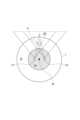
次に、閉じた死角の変化の態様について説明する。図6の(A)は、視野内及び閉じた死角の一例を説明する上面図、図6の(B)は開いた死角の発生の一例を説明する上面図、図6の(C)は閉じた死角から開いた死角への変化の一例を説明する上面図である。なお、図中では、車両2は省略されており、外部センサ3のセンサセット30のみ図示される。図6の(A)に示されるように、センサセット30には視野領域10と閉じた死角94が存在する。視野領域10の外の位置から歩行者Hが視野領域10内に進入するとする。Next, the manner in which a closed blind spot changes will be described. FIG. 6A is a top view illustrating an example of a blind spot within the field of view and a closed blind spot, FIG. 6B is a top view illustrating an example of an open blind spot, and FIG. 6C is a top view illustrating an example of a change from a closed blind spot to an open blind spot. Note that the
図6の(B)に示されるように、歩行者Hが視野領域10内に進入した場合、センサセット30からみて歩行者Hの奥の領域に、動的死角91である開いた死角93が生じる。そして、図6の(C)に示されるように、歩行者Hがさらに移動し、閉じた死角94に到達したとする。開いた死角93と閉じた死角94が重複した場合、つまり、開いた死角93と閉じた死角94が接続した場合(図中の接続箇所X参照)、閉じた死角94であった領域に「観測可能な距離よりも遠方にいる動的物体が視野内を経由せずに侵入できる」ようになる。このように、開いた死角93と閉じた死角94とが接続した場合、閉じた死角94の定義が破綻し、開いた死角93の定義が成立する。図7は、視野内及び閉じた死角の一例を説明する上面図である。図7に示される例においては、センサセット30がセンサ31~33を含む。その他は図6の(A)と同一である。このような場合であっても、センサセット30からみて歩行者Hの奥の領域に、動的死角91である開いた死角93が生じる。そして、開いた死角93と閉じた死角94が接続した場合、閉じた死角94であった領域に「観測可能な距離よりも遠方にいる動的物体が視野内を経由せずに侵入できる」ようになる。例えば、動的死角91である開いた死角93内に隠れた物体が、センサセット30によって検出されることなく閉じた死角94に進入してしまうおそれがある。なお、歩行者Hは、障害物の一例である。障害物(物体の一例)は、歩行者Hのような動的障害物でもよいし、柱のような静的障害物でもよい。以上、障害物によって閉じた死角94が開いた死角93に変化することがある。As shown in FIG. 6B, when a pedestrian H enters the field of
次に、閉じた死角の変化の他の態様について説明する。図8の(A)は、閉じた死角の変化の一例を説明する上面図である。なお、図中では、車両2は省略されており、外部センサ3のセンサセット30のみ図示される。図8の(A)に示されるように、センサセット30には視野領域10と閉じた死角94とが存在する。そして、センサセット30の視野領域10内及び閉じた死角94内に壁Wが存在する。この場合、センサセット30からみて壁Wの奥の領域は開いた死角93となる。壁Wによって開いた死角93と閉じた死角94が遮蔽されており、かつ、壁Wの両端が視野領域10内に存在するため、閉じた死角94には「観測可能な距離よりも遠方にいる動的物体が視野内を経由せずに侵入できない」状態が維持されている。つまり、図8の(A)に示される壁Wは、開いた死角93と閉じた死角94とを接続しない障害物であり、閉じた死角94の一部を開いた死角93Aに変化させている。このように、開いた死角93と閉じた死角94とを接続しない障害物は、閉じた死角94の領域を狭める効果がある。Next, other aspects of the change in the closed blind spot will be described. FIG. 8A is a top view illustrating an example of the change in the closed blind spot. In the figure, the
図8の(B)は閉じた死角の変化の他の例を説明する上面図である。なお、図中では、車両2は省略されており、外部センサ3のセンサセット30のみ図示される。図8の(B)に示されるように、センサセット30には視野領域10と閉じた死角94とが存在する。そして、センサセット30の視野領域10内及び閉じた死角94内に壁Wが存在する。ここで、図8の(B)に示される例では、壁Wの一端が閉じた死角94内に存在する。このような場合、開いた死角93と閉じた死角94とが接続可能になる(図中の接続箇所X参照)。つまり、閉じた死角94は、「観測可能な距離よりも遠方にいる動的物体が視野内を経由せずに進入できる死角」へと変化する。これにより、図中の閉じた死角94は、開いた死角93へと変更される。8B is a top view illustrating another example of the change in the closed blind spot. In the figure, the
次に、開いた死角が閉じた死角へと変化する態様について説明する。図8の(C)は、(C)は開いた死角から閉じた死角への変化の一例を説明する上面図である。なお、図中では、車両2は省略されている。また、図8の(C)に示される外部センサ3は、一例として、図5の(B)に示される超広角センサである。図8の(C)に示されるように、外部センサ3を障害物である壁Wに近づける。これにより、開いた死角93が、視野領域10と壁Wによって閉じ込められ、閉じた死角94に変化する。つまり、障害物によって「観測可能な距離よりも遠方にいる動的物体が視野内を経由せずに進入できなくなる」領域が画成される。このように、閉じ込められた開いた死角93は、閉じた死角94へと変更される場合がある。Next, a manner in which an open blind spot changes to a closed blind spot will be described. FIG. 8C is a top view illustrating an example of a change from an open blind spot to a closed blind spot. Note that the
(ECUの各機能)
図1に示される物体検出装置1は、上述した閉じた死角94の性質を利用して死角領域における物体の有無を検出する。物体検出装置1のECU6は、機能的な構成として、車両情報取得部11、障害物認識部12、死角情報DB13、出入状況取得部14(取得部の一例)、判定部15、移動体制御部16、人数取得部17、及び報知制御部18を備える。物体検出装置1は、物体検出機能を実現するために、出入状況取得部14及び判定部15を備えており、物体検出機能の補助又は付加的な機能を実現するために、車両情報取得部11、障害物認識部12、死角情報DB13、移動体制御部16、人数取得部17、及び報知制御部18を備えている。(ECU functions)
The
車両情報取得部11は、車両2の状態に関する情報を取得する。車両情報取得部11は、一例として、GPS受信機5によって取得された車両2の位置情報、内部センサ4によって検出された車両2の向きなどを取得する。車両情報取得部11は、位置情報の補間(内挿)のために、車両2の速度情報を取得してもよい。例えば、時刻t1,t2,t3(t1<t2<t3)のそれぞれの車両2の位置がp1,p2,p3と設定される場合において、時刻t1,t3の車両2の位置が取得されたとする。この場合、車両情報取得部11は、時刻t2の車両2の位置を、p2=p1+(p3-p1)*(t2-t1)/(t3-t1)として算出する。あるいは、車両情報取得部11は、時刻t1,t3の車両2の速度v1,v3が取得される場合には、時刻t2の車両2の位置を、p2=p1+(v1+v3)/2*(t2-t1)として算出してもよい。The vehicle
障害物認識部12は、障害物を認識する。障害物は、車両2の周囲に存在する物体であり、道路構造物又は植物などの静止物体、又は、他車両などの動的物体を含む。障害物認識部12は、例えば外部センサ3の検出結果に基づいて、障害物の位置、速度、属性などを認識する。属性は、歩行者・二輪車・車両・静止物体などを含む。The
死角情報DB13は、閉じた死角94に関する情報を格納する。閉じた死角94に関する情報とは、閉じた死角94の立体構造(位置及び立体形状)を示す三次元情報である。上述したとおり、閉じた死角94は、「観測可能な距離よりも遠方にいる動的物体が視野内を経由しなければ進入できない静的死角92」であり、静的死角92は、「外部センサ3にとって固定的に存在する死角9」である。このため、外部センサ3が車両2に固定され、画角が固定されている場合には、閉じた死角94の位置及び立体形状は固定される。The blind
閉じた死角94に関する情報は、動的に更新されてもよい。例えば、外部センサ3の視野が動的に変化する場合には、視野の変化に合わせて閉じた死角94に関する情報が更新される。外部センサ3の視野が動的に変化する場合の一例は、外部センサ3がロボットアームの先に取り付けられている場合、ミラーなどの光学部材を用いて注視する方向及び視野角を制御できる場合などである。この場合、死角情報DB13は、時刻情報と閉じた死角94の位置及び立体形状とを記憶してもよい。死角情報DB13は、開いた死角93から閉じた死角94へと変更になった旨、あるいは、閉じた死角94から開いた死角93へと変更になった旨を記録してもよい。The information on the closed
あるいは、他者の情報に基づいて外部センサ3の視野内が拡張した場合には、視野の変化に合わせて閉じた死角94に関する情報が更新されてもよい。例えば、駐車場などに固定されたインフラカメラや周辺他車のセンサからの情報を無線等によって取得することで閉じた死角94の立体形状を小さくしたり、開いた死角93を閉じた死角94に変化させたり、閉じた死角94に関する情報を削除してもよい。Alternatively, when the field of view of the
あるいは、環境による死角形状の変化が発生した場合には、閉じた死角94に関する情報が更新されてもよい。例えば、逆光により視野角の一部の情報が取得できず死角になる場合がある。あるいは、ライダーは濃霧が発生すると光が拡散され情報が取得できなくなる場合がある。これらのような環境要因によって死角の形状が変化した場合、その立体構造が時刻とともに記憶されてもよい。Alternatively, if the shape of the blind spot changes due to the environment, the information about the closed
あるいは、図6の(C)、図8の(A)~図8の(C)に示されるように、閉じた死角94が開いた死角93へと変化した場合、あるいは開いた死角93が閉じた死角94へと変化した場合には、閉じた死角94に関する情報が更新されてもよい。障害物によって変化した閉じた死角94の立体構造が時刻とともに記憶されてもよい。Alternatively, as shown in FIG. 6C and FIG. 8A to FIG. 8C, when a closed
出入状況取得部14は、外部センサ3の検出結果に基づいて、外部センサ3の閉じた死角94への障害物の出入状況を取得する。閉じた死角94への障害物の出入状況とは、閉じた死角94への障害物の進入及び退出である。出入状況取得部14は、障害物認識部12により取得された障害物の位置(外部センサ3の検出結果)の変化と、死角情報DB13から取得された閉じた死角94に関する情報とに基づいて、障害物の出入状況を取得する。例えば、障害物が閉じた死角94に向かって移動し、閉じた死角94と重なり、障害物を外部センサ3で検出できない状態となった場合、出入状況取得部14は、障害物が閉じた死角94へ進入したと判定する。あるいは、例えば、閉じた死角94から出現した障害物が外部センサ3によって検出された場合には、出入状況取得部14は、障害物が閉じた死角94から退出したと判定する。The entry/exit
判定部15は、出入状況取得部14によって取得された出入状況に基づいて、閉じた死角94における障害物の有無を判定する。上述したとおり、閉じた死角94は、障害物が観測可能な距離よりも遠方から近づくときに必ず外部センサ3の視野内を経由する。図9の(A)は、視野内及び閉じた死角の一例を説明する上面図、図9の(B)は視野内及び閉じた死角の時系列の遷移を説明する上面図である。図9の(A)に示されるように、発進前の静止した車両2においては、車両2の近傍に閉じた死角94が存在しており、閉じた死角94に動的物体(人又は二輪車など)が存在するか不明である。これに対して、図9の(B)では走行中の車両2が示されている。図中では、二つの異なる時刻における死角が重複表示されており、過去の死角が破線で示される。閉じた死角94は、異なる二つの時刻にわたって閉じた死角である領域94Aと、過去は視野内であり、現在は閉じた死角に含まれる領域94Bを含む。領域94Aは、動的物体が存在するか否か不明である。しかし、領域94Bは、過去において既に観測しており、その領域が死角になっただけである。そのため、過去の観測における動的物体の有無がそのまま現在の状態に援用できる。なお、図9の(B)に示される例では二つの異なる時刻のみを取り扱ったが、より多くの時刻を利用してもよい。これにより、領域94Aは存在しなくなり、すべての閉じた死角94は領域94Bのように過去の観測情報を利用可能な領域となる。そして、外部センサ3による時系列の検出結果を用いて「閉じた死角94に動的物体が存在しない」と観測できているのであれば、その後に車両2が静止したとしても(視野内を経由した動的物体が侵入しない限り)閉じた死角94に動的物体は存在せず、車両2は安全に前方に進行することが可能である。The
なお、上述した時系列の検出結果を用いる場合であっても、自動運転システム起動時など、閉じた死角94の形成直後においては、閉じた死角94に動的物体(人又は二輪車など)が存在するか不明である。移動体制御部16は、車両2が停止しており、かつ、閉じた死角94に障害物が存在しないことを示す情報を取得できていない場合には、障害物が存在しないことを示す情報を取得できていない閉じた死角に対応する位置が外部センサ3の視野領域10内に入るように車両2を移動させる。図10の(A)は閉じた死角の一例を説明する図、図10の(B)は閉じた死角の中に障害物が存在しないことを確認する動作を説明する図である。例えば、図10の(A)に示されるように、車両2の前方の地点Cに閉じた死角94が存在し、かつ、動的物体の有無が不明であるとする。この場合、図10の(B)に示されるように、移動体制御部16は、アクチュエータ8を動作させて、地点Cが視野内に入るように車両2を後退させる。車両2が後退することにより、既に物体が存在していないことが確認されている地点Bに閉じた死角94を重ねることができる。このような動作により、動的物体が存在しない閉じた死角94を能動的に作り出すことができる。Even when the above-mentioned time series detection results are used, immediately after the formation of the closed
判定部15は、閉じた死角94に障害物が存在しないことを示す情報を取得し、情報を取得した後において障害物の閉じた死角94への進入が検出されない場合には、閉じた死角94に障害物は存在しないと判定してもよい。閉じた死角94に障害物が存在しないことを示す情報は、他の車載センサで検出された検出結果又は外部インフラから取得されてもよい。なお、判定部15は、閉じた死角94に障害物が存在しないことを示す情報ではなく、閉じた死角94に存在する障害物の個数を予め取得してもよい。この場合であっても、判定部15は、最初に存在した障害物の個数と、閉じた死角94へ進入した障害物の個数と、閉じた死角94から退出した障害物の個数とに基づいて物体の有無を判定することができる。The
他の車載センサを用いた一例として、例えば車室内カメラが挙げられる。車両2に乗員が乗降することによって、閉じた死角94に人が進入するシーンが想定される。このような場合、人数取得部17は、閉じた死角94から車両2へ乗り込む人数及び車両2から閉じた死角94へ降りる人数を取得する。具体的には、車室内カメラによって降車人数を数え上げ、閉じた死角94から出ていく人数との差分を照合する。これにより、閉じた死角94内に人が残っているか否かを判定することができる。あるいは、車重センサと敷設された重量計(例えばバス停に設置された重量計)を用いて「乗員が乗降した前後での車重変化」と「バス停の人の重量変化」が等しければ、閉じた死角94内に人はいないと判定することもできる。あるいは、車両2のドア開閉時には「閉じた死角94内に人がいるか不明な状態になる(Unknownな状態又は初期状態)」とすることもできる。乗員が目視によって、閉じた死角94に障害物は存在しないことを確認し、その後に車両2が発進してもよい。As an example of using other on-board sensors, for example, an in-vehicle camera can be mentioned. It is assumed that a scene will occur in which a person enters the closed
判定部15は、車両2の周囲に複数の閉じた死角94が存在する場合には、閉じた死角94ごとに、上述した物体の有無の判定を行ってもよい。図10の(C)は、複数の閉じた死角を説明する図である。図10の(C)では、図5の(B)に示される超広角センサと、2つの側方センサとが車両2に設けられている。超広角センサは、視野領域10A内に存在する物体を検出可能であり(境界線LA)、車両2の近傍に閉じた死角が存在する。閉じた死角は、視野領域10Bの左側方センサ(境界線LB)と、視野領域10Cの右側方センサ(境界線LC)とによって2つに分割される。図中の例では、車両2の後方に閉じた死角94Aが存在し、車両2の前方に閉じた死角94Bが存在する。この場合、判定部15は、閉じた死角94A,94Bごとに物体の有無を判定する。これによって、例えば閉じた死角94Bに物体が存在し、閉じた死角94Aに物体が存在しないといった判定が可能となるので、死角に物体が存在する場合であっても、物体と接触しない方向に車両2を移動させることが可能になる。When there are multiple closed
判定部15は、判定結果を自動運転システムなどに出力する。自動運転システムは、閉じた死角94に動的物体が存在しないと判定された場合、車両2は進行可能であると判定する。自動運転システムは、閉じた死角94に動的物体が存在すると判定された場合、動的物体が閉じた死角94の外に出るまでは発進しないなどの対応を行う。The
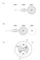
報知制御部18は、外部センサ3の閉じた死角94に関する情報を車両2の乗員に報知させたり、外部センサ3の閉じた死角94に関する情報を車両2の外部に報知させたりする。図11の(A)は物体検出装置によって表示される画面例である。図11の(A)に示されるように、車両2は、車室内に向けて情報を表示する車内HMI71を備える。報知制御部18は、車内HMI71に外部センサ3の閉じた死角94に関する情報を表示させる。図11の(B)は物体検出装置の外向けの報知を説明する上面図である。図11の(B)に示されるように、車両2は、車外に向けて情報を表示するディスプレイ721及び722を備える。報知制御部18は、例えば、閉じた死角94Aに動的物体が存在すると判定された場合、閉じた死角94Aに対応するディスプレイ722に、外部センサ3の閉じた死角94に関する情報を表示させる。報知制御部18は、動的物体が車両2の死角に入っていることを示す情報を表示させてもよいし、死角から退避することを促す情報を出力させてもよい。あるいは、報知制御部18は、死角情報DB13から閉じた死角94の形状情報を取得し、取得された形状情報に基づいて、閉じた死角94の形状が視認可能なように路面に光を投影してもよい。そして、報知制御部18は、閉じた死角94を投影しながら、死角から退避することを促す情報を出力させてもよい。The
(物体検出装置の動作)
図12は、物体検出装置の動作を説明するフローチャートである。図12に示されるフローチャートは、例えば車両2に備わる物体検出機能の開始ボタンがONされたタイミングで、物体検出装置1によって実行される。(Operation of the object detection device)
12 is a flowchart illustrating the operation of the
図12に示されるように、物体検出装置1の出入状況取得部14は、死角情報取得処理(ステップS10)として、死角情報DB13から閉じた死角94の情報を取得する。続いて、物体検出装置1の車両情報取得部11は、車両情報取得処理(ステップS12)として、車両2の位置を取得する。続いて、物体検出装置1の障害物認識部12は、障害物認識処理(ステップS14)として、障害物を認識する。最後に、物体検出装置1の出入状況取得部14及び判定部15は、判定処理(ステップS16)として、外部センサ3の閉じた死角94への物体の出入状況を取得し、出入状況に基づいて閉じた死角94における物体の有無を判定する。判定処理(ステップS16)が終了すると図12に示されるフローチャートは終了する。フローチャートが終了すると、終了条件が満たされるまで、再度、ステップS10から処理が実行される。終了条件は、例えば物体検出機能の終了ボタンがONされた場合などである。なお、ステップS10~ステップS14の実行順は特に限定されず、また、ステップS10~ステップS14は同時に行われてもよい。12, the entry/exit
(実施形態のまとめ)
物体検出装置1によれば、外部センサ3の閉じた死角94への障害物の出入状況が出入状況取得部14によって取得される。そして、閉じた死角94における障害物の有無が、判定部15によって出入状況に基づいて判定される。外部センサ3の閉じた死角94とは、例えば外部センサ3の視野内を経由しなければ進入できない死角である。つまり、外部センサ3の閉じた死角94への障害物の出入りが外部センサ3によって検出された場合、外部センサ3の閉じた死角94に存在する障害物の個数は増減することになる。物体検出装置1は、外部センサ3の閉じた死角94への障害物の出入状況を把握することにより、死角に存在する障害物の移動位置の推定を行わずに死角領域における物体の有無を判定することができる。つまり、物体検出装置1は、死角となる対象領域を直接観測することなく対象領域における障害物の有無を判定することができる。(Summary of the embodiment)
According to the
物体検出装置1によれば、外部センサ3の閉じた死角94に存在する障害物の個数が0であることを予め把握し、外部センサ3の閉じた死角94に存在する障害物の個数が増加していないことを検出することにより、死角において障害物が存在しないことを判定することができる。物体検出装置1によれば、外部センサ3の閉じた死角94に存在する障害物の個数を予め把握し、外部センサ3の閉じた死角94に存在する障害物の個数の増減を検出することにより、死角における障害物の有無を判定することができる。According to the
物体検出装置1によれば、外部センサ3の閉じた死角94に存在する人数を人数取得部17によって予め把握し、外部センサ3の閉じた死角94に存在する人数の増減を検出することにより、死角における障害物の有無を判定することができる。According to the
物体検出装置1によれば、車両2が停止しており、かつ、閉じた死角94に障害物が存在しないことを示す情報を取得できていない場合には、障害物が存在しないことを示す情報を取得できていない閉じた死角94に対応する位置が外部センサ3の視野内に入るように車両2を移動させる。これにより、物体検出装置1は、閉じた死角94に障害物が存在しないことを示す情報を能動的に把握することができる。According to the
物体検出装置1によれば、外部センサ3の閉じた死角94に関する情報が運転者に報知される。また、物体検出装置1によれば、外部センサ3の閉じた死角94に関する情報が、車外の外部センサ3の閉じた死角94に向けて報知される。According to the
以上、種々の例示的実施形態について説明してきたが、上述した例示的実施形態に限定されることなく、様々な省略、置換、及び変更がなされてもよい。Although various exemplary embodiments have been described above, various omissions, substitutions, and modifications may be made without being limited to the above-described exemplary embodiments.
1…物体検出装置、2…車両、14…出入状況取得部(取得部の一例)、15…判定部、16…移動体制御部、17…人数取得部、18…報知制御部。1... object detection device, 2... vehicle, 14... entry/exit status acquisition unit (one example of an acquisition unit), 15... determination unit, 16... mobile object control unit, 17... number of people acquisition unit, 18... notification control unit.
Claims (7)
Translated fromJapanese前記センサの検出結果に基づいて、前記センサの閉じた死角への前記物体の出入状況を取得する取得部と、
前記出入状況に基づいて、前記閉じた死角における前記物体の有無を判定する判定部と、
前記閉じた死角から前記移動体へ乗り込む人数及び前記移動体から前記閉じた死角へ降りる人数を取得する人数取得部と、
を備え、
前記判定部は、前記乗り込む人数及び前記降りる人数に基づいて前記閉じた死角における物体の有無を判定する、物体検出装置。An object detection device that determines whether or not an object is present in a blind spot of a sensor mounted on a moving object,
an acquisition unit that acquires an entry/exit status of the object into/from a blind spot closed by the sensor based on a detection result of the sensor;
A determination unit that determines the presence or absence of the object in the closed blind spot based on the entry/exit situation;
a number of people acquiring unitthat acquires the number of people getting on to the moving body from the closed blind spot and the number of people getting off from the moving body into the closed blind spot;
Equipped with
The object detection device, wherein the determination unit determines whether or not an object is present in the closed blind spot based on the number of people getting in and the number of people getting out.
前記センサの検出結果に基づいて、前記センサの閉じた死角への前記物体の出入状況を取得する取得部と、
前記出入状況に基づいて、前記閉じた死角における前記物体の有無を判定する判定部と、
前記移動体が停止しており、かつ、前記閉じた死角に前記物体が存在しないことを示す情報を取得できていない場合には、前記物体が存在しないことを示す情報を取得できていない前記閉じた死角に対応する位置が前記センサの視野内に入るように前記移動体を移動させる移動体制御部と、
を備える、物体検出装置。An object detection device that determines whether or not an object is present in a blind spot of a sensor mounted on a moving object,
an acquisition unit that acquires an entry/exit status of the object into/from a blind spot closed by the sensor based on a detection result of the sensor;
A determination unit that determines the presence or absence of the object in the closed blind spot based on the entry/exit situation;
a moving body control unit that, when the moving body is stopped and information indicating that the object does not exist in the closed blind spot cannot be obtained, moves the moving body so that a position corresponding to the closed blind spot where information indicating that the object does not exist cannot be obtained is within a field of view of the sensor;
Anobject detection device comprising:
Priority Applications (3)
| Application Number | Priority Date | Filing Date | Title |
|---|---|---|---|
| JP2021119413AJP7537391B2 (en) | 2021-07-20 | 2021-07-20 | Object detection device |
| US17/809,762US12258006B2 (en) | 2021-07-20 | 2022-06-29 | Object detection device |
| CN202210854894.5ACN115635959A (en) | 2021-07-20 | 2022-07-18 | Object detection device |
Applications Claiming Priority (1)
| Application Number | Priority Date | Filing Date | Title |
|---|---|---|---|
| JP2021119413AJP7537391B2 (en) | 2021-07-20 | 2021-07-20 | Object detection device |
Publications (2)
| Publication Number | Publication Date |
|---|---|
| JP2023015557A JP2023015557A (en) | 2023-02-01 |
| JP7537391B2true JP7537391B2 (en) | 2024-08-21 |
Family
ID=84940484
Family Applications (1)
| Application Number | Title | Priority Date | Filing Date |
|---|---|---|---|
| JP2021119413AActiveJP7537391B2 (en) | 2021-07-20 | 2021-07-20 | Object detection device |
Country Status (3)
| Country | Link |
|---|---|
| US (1) | US12258006B2 (en) |
| JP (1) | JP7537391B2 (en) |
| CN (1) | CN115635959A (en) |
Families Citing this family (1)
| Publication number | Priority date | Publication date | Assignee | Title |
|---|---|---|---|---|
| JP2025133415A (en)* | 2024-03-01 | 2025-09-11 | 株式会社三井E&S | Obstacle detection system and obstacle detection method |
Citations (2)
| Publication number | Priority date | Publication date | Assignee | Title |
|---|---|---|---|---|
| JP2009154775A (en) | 2007-12-27 | 2009-07-16 | Toyota Central R&D Labs Inc | Warning device |
| JP2018101295A (en) | 2016-12-20 | 2018-06-28 | トヨタ自動車株式会社 | Object detection device |
Family Cites Families (3)
| Publication number | Priority date | Publication date | Assignee | Title |
|---|---|---|---|---|
| US12036980B2 (en)* | 2018-08-22 | 2024-07-16 | Mitsubishi Electric Corporation | Course prediction device, computer readable medium, and course prediction method |
| TWI722382B (en)* | 2019-02-01 | 2021-03-21 | 為升電裝工業股份有限公司 | Vehicle radar device and system thereof |
| JP7145815B2 (en) | 2019-05-27 | 2022-10-03 | 日立Astemo株式会社 | electronic controller |
- 2021
- 2021-07-20JPJP2021119413Apatent/JP7537391B2/enactiveActive
- 2022
- 2022-06-29USUS17/809,762patent/US12258006B2/enactiveActive
- 2022-07-18CNCN202210854894.5Apatent/CN115635959A/enactivePending
Patent Citations (2)
| Publication number | Priority date | Publication date | Assignee | Title |
|---|---|---|---|---|
| JP2009154775A (en) | 2007-12-27 | 2009-07-16 | Toyota Central R&D Labs Inc | Warning device |
| JP2018101295A (en) | 2016-12-20 | 2018-06-28 | トヨタ自動車株式会社 | Object detection device |
Also Published As
| Publication number | Publication date |
|---|---|
| CN115635959A (en) | 2023-01-24 |
| US12258006B2 (en) | 2025-03-25 |
| JP2023015557A (en) | 2023-02-01 |
| US20230022104A1 (en) | 2023-01-26 |
Similar Documents
| Publication | Publication Date | Title |
|---|---|---|
| CN111830859B (en) | Vehicle remote indication system | |
| CN109466542B (en) | Vehicle control device, vehicle control method, and storage medium | |
| US10643474B2 (en) | Vehicle control device, vehicle control method, and recording medium | |
| US11086335B2 (en) | Driving assistance system and vehicle comprising the same | |
| US10114371B2 (en) | Vehicle control system, vehicle control method, and vehicle control program | |
| US20190256087A1 (en) | Autonomous vehicle and operating method thereof | |
| EP4189953B1 (en) | Apparatus, system and method for enhanced driver vision based on road level characteristics | |
| JP2019197467A (en) | Vehicle control device | |
| KR20190063667A (en) | Autonomous vehicle and method of controlling the same | |
| JP7626632B2 (en) | Information processing device, information processing method, and program | |
| JP7666549B2 (en) | Image Processing Device | |
| US20230400321A1 (en) | Ar display device for vehicle and method for operating same | |
| US11610488B2 (en) | Notification device and vehicle control device | |
| JP2025061744A (en) | Information processing device, information processing system, and program | |
| JP6633957B2 (en) | Peripheral risk display | |
| JP7537391B2 (en) | Object detection device | |
| JP2025013519A (en) | Information processing device, information processing method, and program | |
| JP6667346B2 (en) | Peripheral risk display | |
| WO2021187118A1 (en) | Automotive display device and automotive display method | |
| JP7271950B2 (en) | vehicle controller | |
| JP2022110841A (en) | Vehicle cruise control system | |
| JP2017182566A (en) | Peripheral risk display device | |
| TWI876714B (en) | Method for vehicle detects stationary objects at high speeds | |
| US20250128687A1 (en) | Vehicular system control method and apparatus | |
| US20250155258A1 (en) | Information processing device, information processing method, and moving body |
Legal Events
| Date | Code | Title | Description |
|---|---|---|---|
| A621 | Written request for application examination | Free format text:JAPANESE INTERMEDIATE CODE: A621 Effective date:20231011 | |
| A977 | Report on retrieval | Free format text:JAPANESE INTERMEDIATE CODE: A971007 Effective date:20240327 | |
| A131 | Notification of reasons for refusal | Free format text:JAPANESE INTERMEDIATE CODE: A131 Effective date:20240402 | |
| A521 | Request for written amendment filed | Free format text:JAPANESE INTERMEDIATE CODE: A523 Effective date:20240521 | |
| TRDD | Decision of grant or rejection written | ||
| A01 | Written decision to grant a patent or to grant a registration (utility model) | Free format text:JAPANESE INTERMEDIATE CODE: A01 Effective date:20240709 | |
| A61 | First payment of annual fees (during grant procedure) | Free format text:JAPANESE INTERMEDIATE CODE: A61 Effective date:20240722 | |
| R150 | Certificate of patent or registration of utility model | Ref document number:7537391 Country of ref document:JP Free format text:JAPANESE INTERMEDIATE CODE: R150 |