JP7536608B2 - Blood Purification Device - Google Patents
Blood Purification DeviceDownload PDFInfo
- Publication number
- JP7536608B2 JP7536608B2JP2020189213AJP2020189213AJP7536608B2JP 7536608 B2JP7536608 B2JP 7536608B2JP 2020189213 AJP2020189213 AJP 2020189213AJP 2020189213 AJP2020189213 AJP 2020189213AJP 7536608 B2JP7536608 B2JP 7536608B2
- Authority
- JP
- Japan
- Prior art keywords
- blood
- circuit
- air
- pump
- dialysis fluid
- Prior art date
- Legal status (The legal status is an assumption and is not a legal conclusion. Google has not performed a legal analysis and makes no representation as to the accuracy of the status listed.)
- Active
Links
Images


Classifications
- A—HUMAN NECESSITIES
- A61—MEDICAL OR VETERINARY SCIENCE; HYGIENE
- A61M—DEVICES FOR INTRODUCING MEDIA INTO, OR ONTO, THE BODY; DEVICES FOR TRANSDUCING BODY MEDIA OR FOR TAKING MEDIA FROM THE BODY; DEVICES FOR PRODUCING OR ENDING SLEEP OR STUPOR
- A61M1/00—Suction or pumping devices for medical purposes; Devices for carrying-off, for treatment of, or for carrying-over, body-liquids; Drainage systems
- A61M1/36—Other treatment of blood in a by-pass of the natural circulatory system, e.g. temperature adaptation, irradiation ; Extra-corporeal blood circuits
- A61M1/3621—Extra-corporeal blood circuits
- A61M1/3653—Interfaces between patient blood circulation and extra-corporal blood circuit
- A61M1/3656—Monitoring patency or flow at connection sites; Detecting disconnections
- A—HUMAN NECESSITIES
- A61—MEDICAL OR VETERINARY SCIENCE; HYGIENE
- A61M—DEVICES FOR INTRODUCING MEDIA INTO, OR ONTO, THE BODY; DEVICES FOR TRANSDUCING BODY MEDIA OR FOR TAKING MEDIA FROM THE BODY; DEVICES FOR PRODUCING OR ENDING SLEEP OR STUPOR
- A61M1/00—Suction or pumping devices for medical purposes; Devices for carrying-off, for treatment of, or for carrying-over, body-liquids; Drainage systems
- A61M1/14—Dialysis systems; Artificial kidneys; Blood oxygenators ; Reciprocating systems for treatment of body fluids, e.g. single needle systems for hemofiltration or pheresis
- A61M1/30—Single needle dialysis ; Reciprocating systems, alternately withdrawing blood from and returning it to the patient, e.g. single-lumen-needle dialysis or single needle systems for hemofiltration or pheresis
- A—HUMAN NECESSITIES
- A61—MEDICAL OR VETERINARY SCIENCE; HYGIENE
- A61M—DEVICES FOR INTRODUCING MEDIA INTO, OR ONTO, THE BODY; DEVICES FOR TRANSDUCING BODY MEDIA OR FOR TAKING MEDIA FROM THE BODY; DEVICES FOR PRODUCING OR ENDING SLEEP OR STUPOR
- A61M1/00—Suction or pumping devices for medical purposes; Devices for carrying-off, for treatment of, or for carrying-over, body-liquids; Drainage systems
- A61M1/14—Dialysis systems; Artificial kidneys; Blood oxygenators ; Reciprocating systems for treatment of body fluids, e.g. single needle systems for hemofiltration or pheresis
- A61M1/16—Dialysis systems; Artificial kidneys; Blood oxygenators ; Reciprocating systems for treatment of body fluids, e.g. single needle systems for hemofiltration or pheresis with membranes
- A61M1/1601—Control or regulation
- A—HUMAN NECESSITIES
- A61—MEDICAL OR VETERINARY SCIENCE; HYGIENE
- A61M—DEVICES FOR INTRODUCING MEDIA INTO, OR ONTO, THE BODY; DEVICES FOR TRANSDUCING BODY MEDIA OR FOR TAKING MEDIA FROM THE BODY; DEVICES FOR PRODUCING OR ENDING SLEEP OR STUPOR
- A61M1/00—Suction or pumping devices for medical purposes; Devices for carrying-off, for treatment of, or for carrying-over, body-liquids; Drainage systems
- A61M1/14—Dialysis systems; Artificial kidneys; Blood oxygenators ; Reciprocating systems for treatment of body fluids, e.g. single needle systems for hemofiltration or pheresis
- A61M1/16—Dialysis systems; Artificial kidneys; Blood oxygenators ; Reciprocating systems for treatment of body fluids, e.g. single needle systems for hemofiltration or pheresis with membranes
- A61M1/1621—Constructional aspects thereof
- A—HUMAN NECESSITIES
- A61—MEDICAL OR VETERINARY SCIENCE; HYGIENE
- A61M—DEVICES FOR INTRODUCING MEDIA INTO, OR ONTO, THE BODY; DEVICES FOR TRANSDUCING BODY MEDIA OR FOR TAKING MEDIA FROM THE BODY; DEVICES FOR PRODUCING OR ENDING SLEEP OR STUPOR
- A61M1/00—Suction or pumping devices for medical purposes; Devices for carrying-off, for treatment of, or for carrying-over, body-liquids; Drainage systems
- A61M1/36—Other treatment of blood in a by-pass of the natural circulatory system, e.g. temperature adaptation, irradiation ; Extra-corporeal blood circuits
- A61M1/3621—Extra-corporeal blood circuits
- A61M1/3643—Priming, rinsing before or after use
- A61M1/3644—Mode of operation
- A61M1/3646—Expelling the residual body fluid after use, e.g. back to the body
- A—HUMAN NECESSITIES
- A61—MEDICAL OR VETERINARY SCIENCE; HYGIENE
- A61M—DEVICES FOR INTRODUCING MEDIA INTO, OR ONTO, THE BODY; DEVICES FOR TRANSDUCING BODY MEDIA OR FOR TAKING MEDIA FROM THE BODY; DEVICES FOR PRODUCING OR ENDING SLEEP OR STUPOR
- A61M1/00—Suction or pumping devices for medical purposes; Devices for carrying-off, for treatment of, or for carrying-over, body-liquids; Drainage systems
- A61M1/36—Other treatment of blood in a by-pass of the natural circulatory system, e.g. temperature adaptation, irradiation ; Extra-corporeal blood circuits
- A61M1/3621—Extra-corporeal blood circuits
- A61M1/3643—Priming, rinsing before or after use
- A61M1/3644—Mode of operation
- A61M1/3649—Mode of operation using dialysate as priming or rinsing liquid
- A—HUMAN NECESSITIES
- A61—MEDICAL OR VETERINARY SCIENCE; HYGIENE
- A61M—DEVICES FOR INTRODUCING MEDIA INTO, OR ONTO, THE BODY; DEVICES FOR TRANSDUCING BODY MEDIA OR FOR TAKING MEDIA FROM THE BODY; DEVICES FOR PRODUCING OR ENDING SLEEP OR STUPOR
- A61M1/00—Suction or pumping devices for medical purposes; Devices for carrying-off, for treatment of, or for carrying-over, body-liquids; Drainage systems
- A61M1/36—Other treatment of blood in a by-pass of the natural circulatory system, e.g. temperature adaptation, irradiation ; Extra-corporeal blood circuits
- A61M1/3621—Extra-corporeal blood circuits
- A61M1/3643—Priming, rinsing before or after use
- A61M1/3644—Mode of operation
- A61M1/3652—Mode of operation using gas, e.g. air
- A—HUMAN NECESSITIES
- A61—MEDICAL OR VETERINARY SCIENCE; HYGIENE
- A61M—DEVICES FOR INTRODUCING MEDIA INTO, OR ONTO, THE BODY; DEVICES FOR TRANSDUCING BODY MEDIA OR FOR TAKING MEDIA FROM THE BODY; DEVICES FOR PRODUCING OR ENDING SLEEP OR STUPOR
- A61M60/00—Blood pumps; Devices for mechanical circulatory actuation; Balloon pumps for circulatory assistance
- A61M60/10—Location thereof with respect to the patient's body
- A61M60/104—Extracorporeal pumps, i.e. the blood being pumped outside the patient's body
- A61M60/109—Extracorporeal pumps, i.e. the blood being pumped outside the patient's body incorporated within extracorporeal blood circuits or systems
- A61M60/113—Extracorporeal pumps, i.e. the blood being pumped outside the patient's body incorporated within extracorporeal blood circuits or systems in other functional devices, e.g. dialysers or heart-lung machines
- A—HUMAN NECESSITIES
- A61—MEDICAL OR VETERINARY SCIENCE; HYGIENE
- A61M—DEVICES FOR INTRODUCING MEDIA INTO, OR ONTO, THE BODY; DEVICES FOR TRANSDUCING BODY MEDIA OR FOR TAKING MEDIA FROM THE BODY; DEVICES FOR PRODUCING OR ENDING SLEEP OR STUPOR
- A61M60/00—Blood pumps; Devices for mechanical circulatory actuation; Balloon pumps for circulatory assistance
- A61M60/20—Type thereof
- A61M60/247—Positive displacement blood pumps
- A61M60/253—Positive displacement blood pumps including a displacement member directly acting on the blood
- A61M60/258—Piston pumps
- A—HUMAN NECESSITIES
- A61—MEDICAL OR VETERINARY SCIENCE; HYGIENE
- A61M—DEVICES FOR INTRODUCING MEDIA INTO, OR ONTO, THE BODY; DEVICES FOR TRANSDUCING BODY MEDIA OR FOR TAKING MEDIA FROM THE BODY; DEVICES FOR PRODUCING OR ENDING SLEEP OR STUPOR
- A61M60/00—Blood pumps; Devices for mechanical circulatory actuation; Balloon pumps for circulatory assistance
- A61M60/30—Medical purposes thereof other than the enhancement of the cardiac output
- A61M60/36—Medical purposes thereof other than the enhancement of the cardiac output for specific blood treatment; for specific therapy
- A61M60/37—Haemodialysis, haemofiltration or diafiltration
- A—HUMAN NECESSITIES
- A61—MEDICAL OR VETERINARY SCIENCE; HYGIENE
- A61M—DEVICES FOR INTRODUCING MEDIA INTO, OR ONTO, THE BODY; DEVICES FOR TRANSDUCING BODY MEDIA OR FOR TAKING MEDIA FROM THE BODY; DEVICES FOR PRODUCING OR ENDING SLEEP OR STUPOR
- A61M60/00—Blood pumps; Devices for mechanical circulatory actuation; Balloon pumps for circulatory assistance
- A61M60/40—Details relating to driving
- A61M60/424—Details relating to driving for positive displacement blood pumps
- A61M60/457—Details relating to driving for positive displacement blood pumps the force acting on the blood contacting member being magnetic
Landscapes
- Health & Medical Sciences (AREA)
- Heart & Thoracic Surgery (AREA)
- Engineering & Computer Science (AREA)
- Life Sciences & Earth Sciences (AREA)
- General Health & Medical Sciences (AREA)
- Anesthesiology (AREA)
- Biomedical Technology (AREA)
- Hematology (AREA)
- Veterinary Medicine (AREA)
- Animal Behavior & Ethology (AREA)
- Public Health (AREA)
- Vascular Medicine (AREA)
- Cardiology (AREA)
- Urology & Nephrology (AREA)
- Mechanical Engineering (AREA)
- Emergency Medicine (AREA)
- Pulmonology (AREA)
- External Artificial Organs (AREA)
Description
Translated fromJapanese本開示は、血液浄化装置に関する。This disclosure relates to a blood purification device.
人間の臓器の一部である腎臓が正常に機能しなくなると(腎不全)、体内の余分な水分を尿にし、体内の不要な老廃物を排出するなどの機能が働かなくなる。腎不全に対応するために、患者からの血液を体外循環させて、血液浄化器により血液中の老廃物および水分を漉す治療(透析治療)を行うための血液浄化装置(透析装置)が使用される。When the kidneys, which are part of the human body, stop functioning normally (renal failure), they no longer function to convert excess fluid into urine and excrete unnecessary waste products from the body. To deal with renal failure, blood purification devices (dialysis devices) are used to circulate the patient's blood outside the body and filter out waste products and fluids from the blood using a blood purifier (dialysis treatment).
血液浄化装置は、患者から血液を抜き取り、血液回路を通じて血液浄化器(血液流路)に血液を導入すると共に、透析液の供給源(透析液供給部)から透析液回路を通じて血液浄化器(透析液流路)に透析液を導入する。そして、血液浄化装置は、血液浄化器を介して血液と透析液との間で老廃物や電解質等の成分を交換して血液を浄化し、浄化した血液を体内に戻す。The blood purification device draws blood from the patient and introduces the blood into the blood purifier (blood flow path) through the blood circuit, while also introducing dialysis fluid from a dialysis fluid supply source (dialysis fluid supply unit) through the dialysis fluid circuit into the blood purifier (dialysis fluid flow path). The blood purification device then purifies the blood by exchanging components such as waste products and electrolytes between the blood and the dialysis fluid via the blood purifier, and returns the purified blood to the body.
透析治療により、血液が血液回路に導入された後、血液が血液回路に残存するため、生理食塩水または透析液を血液回路に流すことによって残存した血液を体内に戻す工程(返血工程)が一般に行われている。返血工程は、血液回路に設けられた血液ポンプを駆動することにより回路内の液体を送液することによって行われる。After blood is introduced into the blood circuit during dialysis treatment, blood remains in the blood circuit, so a process (blood return process) is generally performed to return the remaining blood to the body by running saline or dialysis fluid through the blood circuit. The blood return process is performed by driving a blood pump installed in the blood circuit to pump the liquid in the circuit.
通常、上述した返血工程が終了すると、その後の工程において血液ポンプを駆動することがある、例えば、後工程として、血液回路内に残存した透析液を抜き出す排液工程が行われることがある。排液工程では、患者に穿刺された穿刺針を抜針してから、血液ポンプを駆動する必要がある。返血工程が終了した後、穿刺針が抜針されないままの状態で、排液工程が開始し、血液ポンプを駆動すると、体内に空気が混入したり、再度、脱血や除水を行う恐れがある。Usually, when the above-mentioned blood return process is completed, the blood pump may be driven in the subsequent process. For example, a drainage process may be performed as a subsequent process to remove the dialysis fluid remaining in the blood circuit. In the drainage process, it is necessary to remove the puncture needle that has been inserted into the patient before driving the blood pump. If the drainage process is started and the blood pump is driven without removing the puncture needle after the blood return process is completed, there is a risk that air may be mixed into the body, or blood and water may have to be removed again.
本実施形態は、返血工程が終了した後、穿刺針が抜針されるまでは血液ポンプを駆動しないようにする血液浄化装置を提供することを目的とする。The purpose of this embodiment is to provide a blood purification device that does not drive the blood pump until the puncture needle is removed after the blood return process is completed.
実施形態に係る血液浄化装置は、患者に穿刺された穿刺針と接続され、患者からの血液が流動する血液回路と、前記血液回路に設けられ、駆動することによって前記血液回路内の液体を送液する血液ポンプと、前記患者から前記穿刺針が抜針されたことを検出する抜針検出部と、前記血液回路内の血液を患者に戻す返血工程を開始させ、前記返血工程が終了したと判定したことに応答して、前記血液ポンプを非活性状態にする、制御装置と、を含み、前記返血工程は、前記血液回路に透析液を導入する透析液導入段階と、前記透析液導入段階の後に前記血液回路に空気を導入する空気導入段階とを含み、前記制御装置は、返血量および/または経過時間に基づいて、前記透析液導入段階を終了させるか否かを判定し、前記透析液導入段階が終了したと判定したことに応答して、前記空気導入段階を開始させる。
The blood purification device according to the embodiment includes a blood circuit connected to a puncture needle inserted into a patient and through which blood from the patient flows, a blood pump provided in the blood circuit and driven to pump liquid in the blood circuit, a needle removal detection unit that detects when the puncture needle is removed from the patient, and a control device that starts a blood return process in which blood in the blood circuit is returned to the patient and deactivates the blood pump in response to determining that the blood return process has been completed. The blood return process includes a dialysate introducing step of introducing dialysate into the blood circuit and an air introducing step of introducing air into the blood circuit after the dialysate introducing step. The control device determines whether or not to terminate the dialysate introducing step based on the amount of returned blood and/or the elapsed time, and starts the air introducing step in response to determining that the dialysate introducing step has been completed .
別の実施形態に係る方法は、患者に穿刺された穿刺針と接続され、患者からの血液が流動する血液回路と、前記血液回路に設けられ、駆動することによって前記血液回路内の液体を送液する血液ポンプと、前記患者から前記穿刺針が抜針されたことを検出する抜針検出部と、を含む血液浄化装置の作動方法であって、前記血液浄化装置が、前記血液回路に透析液を導入する透析液導入段階を実行するよう前記血液ポンプを制御するステップと、返血量および/または経過時間に基づいて、前記透析液導入段階を終了させるか否かを判定するステップと、前記透析液導入段階が終了したと判定したことに応答して、前記血液回路に空気を導入する空気導入段階を開始するステップと、前記空気導入段階が終了したと判定した後、前記穿刺針が抜針されたことを検出するまで、前記血液ポンプを非活性状態にするステップと、を含む。 A method according to another embodiment is a method for operating a blood purification device including a blood circuit connected to a puncture needle insertedinto a patient and through which blood from the patient flows, a blood pump provided in the blood circuit and driven to pump liquid in the blood circuit, and a needle removal detection unit that detects when the puncture needle is removed from the patient,the method including the steps of :the blood purification devicecontrolling the blood pump to perform a dialysate introduction step of introducing dialysate into the blood circuit; determining whether or not to terminate the dialysate introduction step based on the amount of returned blood and/or the elapsed time;starting an air introduction stepof introducing air into the blood circuit in response to determining that the dialysate introduction step has ended; and, after determining thatthe air introduction step has ended, keeping the blood pump in an inactive state until it is detected that the puncture needle has been removed.
実施形態に係る血液浄化装置によれば、返血工程が終了した後、穿刺針が抜針されないままの状態で血液ポンプを駆動することを防止することができる。The blood purification device according to the embodiment can prevent the blood pump from being driven when the puncture needle is not removed after the blood return process is completed.
以下、添付図面を参照して、実施形態に係る血液浄化装置を説明する。実施形態に係る血液浄化装置は、透析治療および血液濾過透析治療などが終了すると行われる返血工程が終了した後、穿刺針が抜針されないままの状態で、血液回路に設けられた血液ポンプを駆動することを防止する。返血工程は、血液回路に透析液を導入し、その後、空気を導入することにより、血液回路に残存した血液を体内に押し出すことによって行われる。The blood purification device according to the embodiment will be described below with reference to the attached drawings. The blood purification device according to the embodiment prevents the blood pump provided in the blood circuit from being driven in a state where the puncture needle is not removed after the blood return process, which is performed when dialysis treatment, hemodiafiltration treatment, etc., is completed. The blood return process is performed by introducing dialysis fluid into the blood circuit, and then introducing air to push the blood remaining in the blood circuit out into the body.
<第1の実施形態>
まず、第1の実施形態を説明する。第1の実施形態では、主に、慢性腎不全などに対して慢性血液浄化療法である透析治療(HD)を行った後、返血工程を行う例を説明する。なお、透析治療は慢性血液浄化療法としての例示にすぎず、本実施形態は、血液濾過治療(HF)および血液濾過透析治療(HDF)などにも適用されてもよい。First Embodiment
First, a first embodiment will be described. In the first embodiment, an example will be described in which a blood returning process is performed after dialysis treatment (HD), which is a chronic blood purification therapy for chronic renal failure, etc. Note that dialysis treatment is merely an example of chronic blood purification therapy, and this embodiment may also be applied to hemofiltration treatment (HF) and hemodiafiltration treatment (HDF), etc.
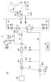
図1は、第1の実施形態に係る血液浄化装置100の構成を示す配管図である。血液浄化装置100は、血液回路1、血液浄化器2、空気導入部3、抜針検出部4、血液濃淡検出部5(本実施形態では、血液濃淡検出部5aおよび5b)、気泡検出部6(本実施形態では、気泡検出部6aおよび6b)、透析液導入ラインIL、排液ラインEL、プライミング液ラインPL、除水ラインRL、バイパスラインBL(本実施形態では、バイパスラインBL1およびBL2)、血液ポンプP1、複式ポンプP2、除水ポンプP3、透析液供給部DS、透析液フィルタDF(本実施形態では、透析液フィルタDF1およびDF2)、電源PS、電極EPa、電極EPb、電極EPc、ならびに制御装置Cを含む。これらの構成要素は例示にすぎず、図示しない他の構成要素が含まれてもよい。また、例えば、血液濃淡検出部5および気泡検出部6などの一部の構成要素は必須の構成要素ではない。Figure 1 is a piping diagram showing the configuration of the
血液回路1は、透析治療のとき、患者Pから脱血した血液を血液浄化器2に導入すると共に、血液浄化器2から導出した血液(浄化された血液)を体内に戻す流路である。血液回路1は、透析液および血液が通ることが可能なチューブが主体として構成される。血液は、患者Pの脱血側(動脈)に穿刺された脱血側穿刺針RNから患者Pの返血側(静脈)に穿刺された返血側穿刺針ANに流れる。血液回路1は、脱血側回路1aおよび返血側回路1bを含む。The
脱血側回路1aは、患者Pから脱血した血液を血液浄化器2に導入する流路である。脱血側回路1aの一端は、脱血側穿刺針RNに取り付けられ、他端は、血液浄化器2に結合される。脱血側回路1aには、開閉弁(電磁弁)V1が設けられる。開閉弁V1の開閉によって、脱血側回路1a内の血液の流れが制御される。返血側回路1bは、血液浄化器2から導出された血液を体内に戻す流路である。返血側回路1bの一端は、返血側穿刺針ANに取り付けられ、他端は、血液浄化器2に結合される。返血側回路1bには、開閉弁(電磁弁)V2が設けられる。開閉弁V2の開閉によって、返血側回路1b内の血液の流れが制御される。The blood
血液ポンプP1は、脱血側回路1aに設けられ、脱血側回路1aから返血側回路1bに進行する方向(以下、送液正方向と称する)、または返血側回路1bから脱血側回路1aに進行する方向(以下、送液逆方向と称する)に血液回路1内で液体を送液する。血液ポンプP1は、固定子および回転子を有するしごき型ポンプから構成され、回転子が回転するよう駆動する。回転子は、制御装置Cによる制御の下、電動モータなどのアクチュエータ(図示しない)によって回転する。血液ポンプP1は、後述する返血工程などにおいて予め定義された動作に従って駆動するが、ユーザによる手動操作によっても駆動する(例えば、図示しない手動ボタンの押下によって)。The blood pump P1 is provided in the blood
血液ポンプP1が正回転することによって、固定子および回転子に挟持された脱血側回路1aをしごき、送液正方向の流れを生じさせる。また、血液ポンプP1が逆回転することによって、脱血側回路1aをしごき、送液逆方向の流れを生じさせる。血液ポンプP1では、パルスモータ(図示せず)を使用した閉ループ制御によって回転子の回転数が制御および検出される。なお、パルスモータを使用した閉ループ制御の代わりに、血液ポンプP1にロータリエンコーダが設けられ、ロータリエンコーダの回転を検出することによって回転子の回転数が制御されてもよい。When the blood pump P1 rotates forward, it squeezes the
血液浄化器2は、ダイアライザとも称され、患者Pの血液を浄化する。血液浄化器2は、内部に設けられた血液浄化膜(図示せず)を含む。血液浄化膜は、側壁に孔を有する中空糸(中空糸膜)が束になって構成される。血液浄化膜の内側が血液流路(図示せず)であり、血液浄化膜(中空糸)の外側が透析液流路(図示せず)である。血液浄化器2を流れる血液は、血液流路を流れ、拡散、限外濾過、またはこれらの両方により、尿毒素物質などの不要な物質が血液浄化膜の孔を通ることによって除去される。血液浄化器2を流れる透析液は、透析液流路を通り、透析液が有する電解質など人体に必要な物質のみが孔を通ることによって血液に補われる。なお、血液浄化膜の内側が透析液流路として、血液浄化膜の外側が血液流路として機能することも可能である。The
透析液導入ラインILは、透析液供給部DSからの透析液を血液浄化器2に供給する、透析液供給部から血液浄化器2までの流路である。透析液導入ラインILは、透析液が通ることが可能なチューブが主体として構成される。透析液導入ラインILには、開閉弁(電磁弁)V3および透析液ポートPが設けられる。開閉弁V3の開閉によって、血液浄化器2への透析液の流れが制御される。透析液ポートPは、透析液を取り出す。血液回路1および透析液導入ラインILは、血液浄化器2の血液浄化膜を介して接続され、血液および透析液を相互に流通させる。The dialysate introduction line IL is a flow path from the dialysate supply unit DS to the
排液ラインELは、血液浄化器2からの透析液の排液を排液部(図示せず)に排出する、血液浄化器2から排液部までの流路である。排液ラインELは、排液が通ることが可能なチューブが主体として構成される。除水ラインRLは、血液浄化器2内の血液からの水分を取り除く、排液ラインELから排液部までの流路である。除水ラインRLは、排液が通ることが可能なチューブが主体として構成される。The drainage line EL is a flow path from the
複式ポンプP2は、透析液導入ラインILおよび排液ラインELにわたって設けられる。複式ポンプP2は、透析液導入ラインILの送液方向下流側に透析液を導入する一方で、排液ラインELの送液方向下流側に透析液の排液を排出する。つまり、複式ポンプP2は、透析液を血液回路1に供給するための透析液供給ポンプ、および透析液を排液部から排出するための排液ポンプとしての役割を果たす。複式ポンプP2の筐体内には、プランジャ(図示せず)が設けられる。プランジャを挟んで、析液導入ラインIL側の容積と、排液ラインEL側の容積に区画されており、プランジャの往復動によって、透析液の導入と排液の排出が連動している。The duplex pump P2 is provided across the dialysate inlet line IL and the drain line EL. The duplex pump P2 introduces dialysis fluid to the downstream side of the dialysate inlet line IL in the flow direction, while discharging the dialysis fluid to the downstream side of the drain line EL in the flow direction. In other words, the duplex pump P2 serves as a dialysis fluid supply pump for supplying dialysis fluid to the
なお、複式ポンプP2の代わりに、透析液供給ポンプ(図示せず)が透析液導入ラインILに設けられ、排液ポンプ(図示せず)が排液ラインELに設けられる構成であってもよい。この場合、透析液供給ポンプおよび排液ポンプは、固定子および回転子を有するしごき型ポンプから構成され、回転子が回転するよう駆動する。回転子は、制御装置Cによる制御の下、電動モータなどのアクチュエータ(図示しない)によって回転する。透析液供給ポンプが駆動(回転)することによって、固定子および回転子に挟持された透析液導入ラインILをしごき、透析液の流れを生じさせる。排液ポンプについても同様である。In addition, instead of the duplex pump P2, a dialysis fluid supply pump (not shown) may be provided in the dialysis fluid introduction line IL, and a drainage pump (not shown) may be provided in the drainage line EL. In this case, the dialysis fluid supply pump and the drainage pump are composed of a squeeze type pump having a stator and a rotor, and are driven to rotate the rotor. The rotor is rotated by an actuator (not shown) such as an electric motor under the control of the control device C. When the dialysis fluid supply pump is driven (rotated), it squeezes the dialysis fluid introduction line IL sandwiched between the stator and the rotor, causing a flow of dialysis fluid. The same applies to the drainage pump.
除水ポンプP3は、除水ラインRLに設けられる。除水ポンプP3は、血液浄化器2内の血液からの水分を取り除くために、除水ラインRLから血液内の水分を排出する。複式ポンプP2を駆動することによって、血液浄化器2に導入される透析液と排出される透析液の量が等量になるため、除水ポンプP3を駆動することによって、血液浄化器2内の血液からの水分を取り除く。The water removal pump P3 is provided in the water removal line RL. The water removal pump P3 discharges water from the blood through the water removal line RL in order to remove water from the blood in the
プライミング液ラインPLは、血液回路1および血液浄化器2にプライミング液(透析液)を導入する、透析液導入ラインILと血液回路1とを連結する連結流路である。具体的には、プライミング液ラインPLは、透析液ポートPから脱血側回路1aまでの流路である。プライミング液ラインPLには、開閉弁(電磁弁)V4が設けられる。開閉弁V4の開閉によって、脱血側回路1aへのプライミング液の流れが制御される。The priming fluid line PL is a connecting flow path that connects the dialysis fluid introduction line IL to the
透析治療の前に、プライミング液で血液回路1および血液浄化器2を満たすことによって(回路内の空気をプライミング液で置換することによって)、回路内の空気を除去するプライミング工程が行われる。プライミング工程では、開閉弁V4が開放し、開閉弁V3が閉鎖することによって、プライミング液がプライミング液ラインPLを流れ、血液回路1および血液浄化器2に導入される。Before dialysis treatment, a priming process is performed to remove air from the circuit by filling the
本実施形態では、透析液導入ラインILおよびプライミング液ラインPLはいずれも、返血工程において、血液回路1に透析液を導入するために使用される。つまり、透析液導入ラインILおよびプライミング液ラインPLは、血液回路1に透析液を導入するための透析液導入回路としての役割を果たす。また、プライミング液ラインPLは、返血工程において、血液回路1に空気を導入するために使用される。つまり、プライミング液ラインPLは、血液回路1に空気を導入する空気導入回路としての役割を果たす。更に、排液ラインELは、返血工程が行われた後の排液工程において、血液回路1からの排液を送液するために使用される。この詳細は後述する。In this embodiment, both the dialysate introduction line IL and the priming solution line PL are used to introduce dialysate into the
バイパスラインBL1およびバイパスラインBL2はそれぞれ、透析液導入ラインILから排液ラインELまでの流路である。バイパスラインBL1には、開閉弁(電磁弁)V5が設けられる。同様に、バイパスラインBL2には、開閉弁(電磁弁)V6が設けられる。開閉弁V5およびV6の開閉によって、透析液導入ラインILから排液ラインELへの透析液の流れが制御される。The bypass lines BL1 and BL2 are each a flow path from the dialysate inlet line IL to the drain line EL. An on-off valve (solenoid valve) V5 is provided in the bypass line BL1. Similarly, an on-off valve (solenoid valve) V6 is provided in the bypass line BL2. The flow of dialysate from the dialysate inlet line IL to the drain line EL is controlled by opening and closing the on-off valves V5 and V6.
バイパスラインBL1およびバイパスラインBL2は、不適切な透析液を血液回路1に流すことを防止するための流路である。例えば、血液浄化装置100には、透析液を加温するための加温器(図示しない)が設けられ、透析治療中にその加温器によって透析液が所定の温度を上回る場合、高温の透析液を血液回路1に流すことを防止するために、透析液がバイパスラインBL1およびバイパスラインBL2を通じて、排液ラインELに流れる。この場合、開閉弁V5および/またはV6が開放する。The bypass lines BL1 and BL2 are flow paths for preventing inappropriate dialysis fluid from flowing through the
空気導入部3は、プライミング液ラインPLを介して血液回路1(脱血側回路1a)に空気を導入する。空気導入部3は、プライミング液ラインPLに接続される。空気導入部3は、透析液導入ラインILおよびプライミング液ラインPLを介して血液回路1に導入された透析液を返血側回路1b(または脱血側回路1a)に押し出し、血液回路1内の血液を患者Pに戻す役割を果たす。この詳細は後述する。The
空気導入部3は、空気ポンプ3a、空気導入路3b、開閉弁(電磁弁)3c、空気フィルタ3d、および空気フィルタ3eを含む。空気ポンプ3aは、内部に回転子を有し、回転子が回転するよう駆動する。回転子は、制御装置Cによる制御の下、電動モータなどのアクチュエータ(図示しない)によって回転する。空気ポンプ3aでは、パルスモータ(図示せず)を使用した閉ループ制御によって回転子の回転数が制御および検出される。なお、パルスモータを使用した閉ループ制御の代わりに、空気ポンプ3aにロータリエンコーダが設けられ、ロータリエンコーダの回転を検出することによって回転子の回転数が制御されてもよい。The
空気ポンプ3aが駆動することによって、空気導入路3bを通じて、プライミング液ラインPLを介して空気が血液回路1に導入される。開閉弁3cは、空気導入路3bとプライミング液ラインPLとの間に設けられる。開閉弁3cの開閉によって、プライミング液ラインPLへの空気の流れが制御される。空気フィルタ3dおよび空気フィルタ3eは、空気中の菌やごみを捕捉し除去する。When the
なお、本実施形態では、空気導入部3は、プライミング液ラインPLに接続されるが、そのような構成に限定されない。空気導入部3は、補液ライン(図示せず)に接続されてもよい。補液ラインは、例えば、血液濾過透析治療において患者からの血液を濾過する量を増大させるために、血液に補液するために透析液を血液回路に導入する流路である。この構成を採用する場合、空気導入部3からの空気は、補液ラインを介して血液回路1に導入される。In this embodiment, the
透析液フィルタDF(透析液フィルタDF1およびDF2)は、透析液供給部DSから供給される透析液に含まれるエンドトキシンなどの物質を捕捉することによって、透析液を清浄化する。透析液フィルタDFはそれぞれ、透析液導入ラインILに設けられ、一次チャンバおよび二次チャンバ(図示せず)を含む。また、透析液フィルタDF1は、内部に透析液浄化膜が設けられる。透析液浄化膜は、側壁に孔を有する中空糸(中空糸膜)が束になって構成される。透析液フィルタDFは、一次チャンバ(透析液浄化膜の内側)から二次チャンバ(透析液浄化膜の外側)に透析液が流動するように構成されている。透析液フィルタDFは、通水することで、水分子の表面張力によって空気を通過させない特性を有する。The dialysate filters DF (dialysate filters DF1 and DF2) purify the dialysate by capturing substances such as endotoxins contained in the dialysate supplied from the dialysate supply unit DS. Each of the dialysate filters DF is provided in the dialysate introduction line IL and includes a primary chamber and a secondary chamber (not shown). The dialysate filter DF1 is provided therein with a dialysate purification membrane. The dialysate purification membrane is composed of a bundle of hollow fibers (hollow fiber membranes) having holes in the side walls. The dialysate filter DF is configured so that the dialysate flows from the primary chamber (inside the dialysate purification membrane) to the secondary chamber (outside the dialysate purification membrane). The dialysate filter DF has the property of not allowing air to pass through due to the surface tension of water molecules when water passes through it.
(脱血側)電極EPaは、脱血側回路1aに設けられる。(返血側)電極EPbは、返血側回路1bに設けられる。電極EPaおよび電極EPbは、可撓性チューブに接続された導電体から構成され、電極EPaは、ワニ口クリップなどの接続手段によって電源PSに電気的に接続される。また、電極EPbは、抜針検出部4に電気的に接続される。なお、電極EPaおよび電極EPbは、血液と物理的に接触するわけではなく、血液回路1を介して電気的に接続される。The (blood removal side) electrode EPa is provided in the blood
電源PSは、高周波数(数kHz~数10kHz)の微弱電流(1mA以下)となる電圧を、電極EPaに印加する。電源PSが電極EPaに電圧を印加することによって、脱血側穿刺針RNおよび返血側穿刺針ANを介して患者Pの血液に電流が流れる。脱血側回路1aおよび返血側回路1bを通じて体外循環する血液は、電流を流す導体であることから、脱血側穿刺針RNおよび返血側穿刺針ANが患者Pに正常に穿刺されていれば、脱血側穿刺針RNおよび返血側穿刺針ANを介して患者Pの血液に電流が流れる。The power supply PS applies a voltage to the electrode EPa that results in a weak current (1 mA or less) at a high frequency (several kHz to several tens of kHz). When the power supply PS applies a voltage to the electrode EPa, a current flows through the patient P's blood via the blood removal side puncture needle RN and the blood return side puncture needle AN. Since the blood circulating outside the body through the blood
(体表側)電極EPcは、患者Pの体表(皮膚)に密着して取り付けられる。電極EPcは、脱血側穿刺針RNおよび返血側穿刺針ANの穿刺部に対して、心臓を挟んだ位置に密着して取り付けられる電極から構成され、患者Pの体内からの電気信号を検出する。また、電極EPcは、抜針検出部4に電気的に接続される(図1では、接続状態を示さず)。電極EPcは、例えば、透析治療において、患者Pから心電図(生体情報)を測定するために使用される。The (body surface) electrode EPc is attached in close contact with the body surface (skin) of patient P. Electrode EPc is composed of electrodes attached in close contact with the puncture points of the blood removal side puncture needle RN and the blood return side puncture needle AN at a position that sandwiches the heart, and detects electrical signals from within the body of patient P. Electrode EPc is also electrically connected to the needle removal detection unit 4 (connection state is not shown in Figure 1). Electrode EPc is used, for example, to measure an electrocardiogram (biological information) from patient P during dialysis treatment.
抜針検出部4は、患者Pに穿刺された脱血側穿刺針RNおよび/または返血側穿刺針ANが抜針されたことを検出する。抜針検出部4は、制御装置Cと接続される。図2は、抜針検出部4、電極EPa、電極EPb、電極EPc、および制御装置Cとの関係を示す。The needle
図2に示すように、電極EPaおよび電極EPbは、差動増幅回路A1に接続されるとともに、電極EPbは、インピーダンス調整回路IAに接続される。また、電極EPcおよびインピーダンス調整回路IAは、差動増幅回路A2に接続される。インピーダンス調整回路IAは、差動増幅回路A1に入力される測定電圧におけるインピーダンス、および差動増幅回路A2に入力される測定電圧におけるインピーダンスを調整する。電極EPaおよび電極EPbから得られる「血液のインピーダンス」と、電極EPbおよび電極EPcから得られる「体液のインピーダンスおよび皮膚のインピーダンス」との間には差があるため、インピーダンス調整回路IAは、この差を調整する。インピーダンス調整回路IAは、負荷抵抗を可変抵抗などにより調整するもの、または心拍成分を抽出できるように自動利得制御(AGC)を使用して調整するものが好ましい。As shown in FIG. 2, electrodes EPa and EPb are connected to a differential amplifier circuit A1, and electrode EPb is connected to an impedance adjustment circuit IA. Electrode EPc and impedance adjustment circuit IA are connected to a differential amplifier circuit A2. The impedance adjustment circuit IA adjusts the impedance at the measurement voltage input to the differential amplifier circuit A1 and the impedance at the measurement voltage input to the differential amplifier circuit A2. Since there is a difference between the "blood impedance" obtained from electrodes EPa and EPb and the "body fluid impedance and skin impedance" obtained from electrodes EPb and EPc, the impedance adjustment circuit IA adjusts this difference. It is preferable that the impedance adjustment circuit IA adjusts the load resistance using a variable resistor or the like, or adjusts using automatic gain control (AGC) so that the heartbeat component can be extracted.
差動増幅回路A1は、電極EPaからの測定電圧と電極EPbからの測定電圧との電圧差を増幅した電気信号を生成する。差動増幅器A2は、電極EPcからの測定電圧とインピーダンス調整回路IAからの測定電圧との電圧差を増幅した電気信号を生成する。Differential amplifier circuit A1 generates an electrical signal by amplifying the voltage difference between the measured voltage from electrode EPa and the measured voltage from electrode EPb. Differential amplifier A2 generates an electrical signal by amplifying the voltage difference between the measured voltage from electrode EPc and the measured voltage from impedance adjustment circuit IA.
さらに、差動増幅回路A1は、整流回路Rを介して抜針検出部4に接続される。差動増幅回路A2は、高域遮断フィルタHFを介して抜針検出部4に接続される。高域遮断フィルタHFは、差動増幅回路A2によって生成された電気信号から、電源PSによって印加された高周波数成分を取り除く。差動増幅回路A1によって生成された電気信号は、抜針検出部4に入力され、差動増幅回路A2によって生成された電気信号は、抜針検出部4に入力される。Furthermore, the differential amplifier circuit A1 is connected to the needle
抜針検出部4は、差動増幅回路A2から入力される電気信号に基づいて、患者Pの体内におけるインピーダンスの変化を検出することによって、所定の生体パラメータ(本実施形態においては心電図)を取得する。すなわち、本実施形態では、電極EPbおよび電極EPcが一対となって患者Pの体内からの電気信号を検出し、抜針検出部4は、検出された電気信号に基づいて、生体パラメータとしての心電図をリアルタイムに取得する。また、抜針検出部4は、電極EPbを流れる電流を監視すると共に、抜針検出部4によって検出された患者Pの体内におけるインピーダンスの変化をリアルタイムに監視する。The needle
制御装置Cは、上述した血液ポンプP1の駆動を制御するなど、血液浄化装置100の構成要素を制御する処理装置である。制御装置Cは、演算装置と記憶装置(RAMおよびROMなどの記憶装置)とを含む。演算装置は、CPUやマイクロコントローラなどのプロセッサ、ASIC(Application Specific Integrated Circuit)、またはFPGA(Field Programmable Gate Array)などで実装されてもよいが、その形式は限定されない。The control device C is a processing device that controls the components of the
抜針検出部4によって監視および検出された電流値およびインピーダンスの変化を示す信号は、制御装置Cに送信される。制御装置Cは、電流値およびインピーダンスの変化を示す信号に基づいて、患者Pから脱血側穿刺針RNおよび/または返血側穿刺針ANが抜針されたか否かを判定する。脱血側穿刺針RNおよび/または返血側穿刺針ANが患者Pから抜針されると、電源PSからの電流が電極EPbまで至らなくなり、抜針検出部4が電流を検出しなくなる(電流値に対応する波形が途切れる)。また、インピーダンスの変化も同様に、検出されなくなる。制御装置Cは、このような状態となったことに応答して、脱血側穿刺針RNおよび/または返血側穿刺針ANが患者Pから抜針されたと判定する。The signal indicating the change in the current value and impedance monitored and detected by the needle
なお、本実施形態では、電源PSが電極EPaに電圧を印加し、抜針検出部4が電極EPbを流れる電流を監視しているが、電圧は、電極EPaおよび電極EPbのいずれかまたは両方に印加されてもよい。電圧が電極EPbに印加される場合、電源PSは電極EPbに接続される。また、抜針検出部4は、電極EPaおよび電極EPbのいずれかまたは両方を流れる電流を監視してもよい。電極EPaを流れる電流を監視する場合、電極EPaは、抜針検出部4に接続される。In this embodiment, the power supply PS applies a voltage to the electrode EPa, and the needle
血液濃淡検出部5(血液濃淡検出部5aおよび血液濃淡検出部5b)は、血液回路1を流れる血液の濃淡を検出する。血液濃淡検出部5aは、脱血側回路1aに設けられ、血液濃淡検出部5bは、返血側回路1bに設けられる。血液濃淡検出部5aおよび血液濃淡検出部5bは、例えば、赤外線を放射する赤外線放射器、およびその光を検出する赤外線センサによって実装される。赤外線は、赤血球の量に応じて血液を透過する量が変わる。よって、血液を透過した赤外線の光量を検出することによって、血液回路1を流れる血液の濃淡を検出することができる。検出された赤外線の光量は、制御装置Cに送信される。制御装置Cは、光量が予め定められた閾値を超えたか否かを判定する。The blood thickness detector 5 (
血液濃淡検出部5によって検出される血液回路1を流れる血液の濃淡は、返血工程における返血量を判定するための基準となる。詳細については後述する。なお、本実施形態では、血液濃淡検出部5aおよび血液濃淡検出部5bがそれぞれ設けられるが、血液濃淡検出部5aおよび血液濃淡検出部5bのいずれか1つのみが設けられてもよい。送液正方向の返血工程が行われる場合、血液濃淡検出部5bが返血側回路1bに設けられることが好ましい。一方、後述する送液逆方向の返血工程が行われる場合、血液濃淡検出部5aが脱血側回路1aに設けられることが好ましい。The blood density of the blood flowing through the
気泡検出部6(気泡検出部6aおよび気泡検出部6b)は、返血工程において血液回路1を流れる血液および/または透析液に気泡が発生したことを検出する。気泡検出部6aは、脱血側回路1aに設けられ、気泡検出部6bは、返血側回路1bに設けられる。気泡検出部6aおよび気泡検出部6bは、例えば、超音波を放射する超音波放射器、およびその超音波を検出する超音波センサによって実装される。The air bubble detector 6 (
超音波センサは、血液および/または透析液の振動に応じた電圧を検出する。気泡は、血液および/または透析液よりも減衰率が高い。よって、気泡検出部6は、電圧値が予め定められた閾値を下回ったことを判定することによって気泡が発生したことを検出することができる。検出された電圧値は、制御装置Cに送信される。制御装置Cは、電圧値が予め定められた閾値を超えたか否かを判定する。The ultrasonic sensor detects a voltage corresponding to the vibration of the blood and/or dialysis fluid. Air bubbles have a higher attenuation rate than blood and/or dialysis fluid. Therefore, the air bubble detection unit 6 can detect the occurrence of air bubbles by determining that the voltage value has fallen below a predetermined threshold. The detected voltage value is transmitted to the control device C. The control device C determines whether the voltage value has exceeded the predetermined threshold.
気泡検出部6によって検出される血液回路1に生じる気泡は、返血工程を途中で終了させるための基準となる。詳細については後述する。なお、本実施形態では、気泡検出部6aおよび気泡検出部6bがそれぞれ設けられるが、気泡検出部6aおよび気泡検出部6bのいずれか1つのみが設けられてもよい。送液正方向の返血工程が行われる場合、気泡検出部6bが返血側回路1bに設けられることが好ましい。一方、後述する送液逆方向の返血工程が行われる場合、気泡検出部6aが脱血側回路1aに設けられることが好ましい。Air bubbles generated in the
次に、図3を参照して、血液ポンプP1の状態モードおよび駆動状態の関係を説明する。本実施形態では、血液ポンプP1は、返血工程が終了してから抜針が検出されるまでは非活性状態になり、抜針が検出されると活性状態にある。非活性状態とは、ユーザによる手動操作などによっても血液ポンプP1が駆動しないことを意味する。つまり、血液ポンプP1は、活性状態にならない限り駆動しない。上述した2つの状態は、2つの状態モード「活性モード」および「非活性モード」として、制御装置Cが状態機械を実装することによって管理される。状態モードは、レジスタ(図示しない)に記憶される。Next, the relationship between the state mode and the drive state of the blood pump P1 will be described with reference to FIG. 3. In this embodiment, the blood pump P1 is in an inactive state from the end of the blood return process until needle removal is detected, and is in an active state when needle removal is detected. The inactive state means that the blood pump P1 is not driven even by manual operation by the user. In other words, the blood pump P1 does not drive unless it is in an active state. The above-mentioned two states are managed by the control device C implementing a state machine as two state modes, "active mode" and "inactive mode." The state modes are stored in a register (not shown).
制御装置Cは、レジスタに記憶された状態モードを参照し、状態モードが活性モードである場合に限り、血液ポンプP1を駆動するよう指示する。よって、状態モードが活性モードにあるとき、血液ポンプP1は、透析治療および返血工程において、制御装置Cにより制御の下、予め定義された動作に従って駆動する。また、状態モードが活性モードにあるとき、血液ポンプP1は、ユーザによる手動操作に応答して(例えば、図示しない手動(駆動)ボタンの押下によって)、制御装置Cの指示によって駆動する。The control device C refers to the status mode stored in the register, and instructs the blood pump P1 to be driven only when the status mode is the active mode. Thus, when the status mode is in the active mode, the blood pump P1 is driven according to predefined operations under the control of the control device C during dialysis treatment and blood return processes. Also, when the status mode is in the active mode, the blood pump P1 is driven by instructions from the control device C in response to manual operation by the user (for example, by pressing a manual (drive) button, not shown).
一方で、状態モードが非活性モードにあるとき、制御装置Cは、駆動ボタンの押下によっても血液ポンプP1を駆動するよう指示しない。つまり、状態モードが非活性モードにあるとき、血液ポンプP1は、駆動しないようロックがかけられる。On the other hand, when the status mode is in the inactive mode, the control device C does not instruct the blood pump P1 to be driven even when the drive button is pressed. In other words, when the status mode is in the inactive mode, the blood pump P1 is locked so that it does not operate.
図3は、血液ポンプP1についての状態モードの遷移、および所定のアクションに対する動作状態を示す。動作状態は、血液ポンプP1が駆動または停止しているかを示す。図3に示す例では、時点T1乃至T6において行われたアクションによって、状態モードが活性モードと非活性モードとの間で遷移し、血液ポンプP1が駆動状態または停止状態のいずれかにある。なお、図3には示さないが、時点T1の前に、透析治療が行われているものとする。Figure 3 shows the state mode transitions for blood pump P1 and the operating state for a given action. The operating state indicates whether blood pump P1 is running or stopped. In the example shown in Figure 3, the state mode transitions between active and inactive modes depending on the actions taken at time points T1 to T6, and blood pump P1 is either running or stopped. Although not shown in Figure 3, it is assumed that dialysis treatment is being performed before time point T1.
図3に示すように、血液ポンプP1に対する状態モードは、初期(デフォルト)の状態モードとして活性モードにあるものとする。このような状態モードの下、時点T1において返血工程が開始すると、制御装置Cの指示によって、血液ポンプP1が駆動(回転)する(停止状態から駆動状態に遷移する)。本実施形態に係る返血工程では、最初に、血液回路1に透析液が導入され(透析液導入段階)、その後、血液回路1に空気が導入される(空気導入段階)。As shown in FIG. 3, the state mode for the blood pump P1 is set to the active mode as the initial (default) state mode. In this state mode, when the blood return process starts at time T1, the blood pump P1 is driven (rotated) (transitions from a stopped state to a driven state) by instruction from the control device C. In the blood return process according to this embodiment, first, dialysis fluid is introduced into the blood circuit 1 (dialysis fluid introduction stage), and then air is introduced into the blood circuit 1 (air introduction stage).
図4は、返血工程における透析液導入段階での透析液の流れを示す。図5は、空気導入段階での透析液および空気の流れを示す。図4および図5において、開閉弁が開放している場合、図に示す開閉弁は網掛けで表示され、開閉弁が閉鎖している場合、図に示す開閉弁は白抜きで表示される。後述する図6以降の図も同様に表示される。Figure 4 shows the flow of dialysis fluid at the dialysis fluid introduction stage in the blood return process. Figure 5 shows the flow of dialysis fluid and air at the air introduction stage. In Figures 4 and 5, when the on-off valve is open, it is displayed in a shaded manner, and when the on-off valve is closed, it is displayed in a white manner. The figures from Figure 6 onwards, which will be described later, are displayed in the same manner.
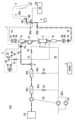
図4に示す透析液導入段階では、制御装置Cによる制御の下、開閉弁V4および開閉弁V2が開放する。また、血液ポンプP1が正回転する。更に、複式ポンプP2が駆動する。これによって、透析液供給部からの透析液は、透析液導入ラインIL、プライミング液ラインPL、脱血側回路1a、血液浄化器2、および返血側回路1bを通る。図4では、この透析液の流れを、太鎖線矢印で示している。この透析液の流れにより、透析液が血液浄化器2および血液回路1(返血側回路1b)に残存した血液を押し出し、血液が体内に戻される。このような状態で、予め定められた量の透析液が血液回路1を流れると、空気導入段階に切り替わる。In the dialysis fluid introduction stage shown in FIG. 4, the on-off valves V4 and V2 are opened under the control of the control device C. In addition, the blood pump P1 rotates forward. Furthermore, the duplex pump P2 is driven. As a result, the dialysis fluid from the dialysis fluid supply unit passes through the dialysis fluid introduction line IL, the priming fluid line PL, the blood
図5に示す空気導入段階に切り替わると、制御装置Cによる制御の下、複式ポンプP2が駆動を停止する。代わりに、空気ポンプ3aが駆動する。これによって、空気は、空気導入路3b、プライミング液ラインPL、脱血側回路1a、血液浄化器2、および返血側回路1bを通る。図5では、この空気の流れを、太実線矢印で示している。この空気の流れにより、透析液導入段階において血液回路1に導入された透析液を介して、血液浄化器2および血液回路1に残存した血液を押し出し、血液が体内に戻される。When the system switches to the air introduction stage shown in FIG. 5, the duplex pump P2 stops operating under the control of the control device C. Instead, the
上記説明した返血工程では、空気を血液回路1に導入することによって返血を行うので、透析液のみを使用して返血を行う場合と比較して、返血に使用する透析液の量を減少させることができる。また、透析液を血液回路1に導入してから空気を血液回路1に導入するので、空気は、透析液を介して血液を体内に押し出すことになるので、患者Pに空気が取り込まれることを防止することができる。In the blood return process described above, blood is returned by introducing air into the
図3の説明に戻ると、図4または図5に示した返血工程が終了すると、つまり、時点T2において、制御装置Cが、返血工程が終了したと判定すると、制御装置Cの指示によって、血液ポンプP1についての状態モードは非活性モードに遷移し、血液ポンプP1は駆動を停止する(駆動状態から停止状態に遷移する)。返血工程の終了は、例えば、一定期間が経過したか否か、および/または返血量が予め定められた閾値に到達したか否かなどに基づいて判定される。Returning to the explanation of FIG. 3, when the blood return process shown in FIG. 4 or FIG. 5 is completed, that is, at time T2, the control device C determines that the blood return process is completed, and in response to an instruction from the control device C, the state mode of the blood pump P1 transitions to the inactive mode, and the blood pump P1 stops operating (transitions from an operating state to a stopped state). The end of the blood return process is determined based on, for example, whether a certain period of time has passed and/or whether the amount of returned blood has reached a predetermined threshold value.
一定期間が経過したか否かは、制御装置Cによって、返血工程の開始からタイマによって計測された時間に基づいて判定されてもよい。返血量が予め定められた閾値に到達したか否かは、制御装置Cによって、血液ポンプP1の回転数が予め定められた閾値を上回ったか否かに基づいて判定されてもよい(上述した閉ループ制御によって、血液ポンプP1の回転数を検出する)。また、返血量が予め定められた閾値に到達したか否かは、制御装置Cによって、血液回路1を流れる血液の濃淡が予め定められた閾値を下回ったか否かに基づいて判定されてもよい(血液濃淡検出部5によって、血液回路1を流れる血液の濃度を検出する)。Whether a certain period of time has elapsed may be determined by the control device C based on the time measured by a timer from the start of the blood return process. Whether the amount of returned blood has reached a predetermined threshold may be determined by the control device C based on whether the rotation speed of the blood pump P1 has exceeded a predetermined threshold (the rotation speed of the blood pump P1 is detected by the closed loop control described above). In addition, whether the amount of returned blood has reached a predetermined threshold may be determined by the control device C based on whether the concentration of blood flowing through the
また、制御装置Cは、返血工程が終了したと判定すると、電源PSおよび抜針検出部4に、脱血側穿刺針RNおよび/または返血側穿刺針ANの抜針を検出(監視)するよう指示する。時点T3において、抜針監視が開始すると、電源PSが電圧を電極EPaに印加し、電極EPaと電極EPbとの間に電流が流れ、患者Pを介して抜針検出部4が電流を検出する。抜針がされると、抜針検出部4は、電極間の通電を検出することができなくなるので(または、電極EPcからのインピーダンスの変化を検出しなくなる)、抜針検出部4が、その非通電の検出を示すインジケータを制御装置Cに送信し、制御装置Cがそのインジケータに基づいて抜針がされたと判定する。When the control device C determines that the blood return process has ended, it instructs the power source PS and the needle
血液ポンプP1についての状態モードが非活性モードにあるとき、例えば、ユーザによって駆動ボタンが押下されても、血液ポンプP1は駆動しない。このような状態では、穿刺針の抜針が検出されるまでは、状態モードが活性モードに遷移せず、血液ポンプP1は駆動しない。When the status mode for the blood pump P1 is in the inactive mode, for example, even if the drive button is pressed by the user, the blood pump P1 will not be driven. In this state, the status mode will not transition to the active mode and the blood pump P1 will not be driven until removal of the puncture needle is detected.
その後、穿刺針の抜針が検出されると、つまり、時点T4において、制御装置Cが、抜針がされたと判定すると、制御装置Cの指示によって、血液ポンプP1についての状態モードは活性モードに遷移する。状態モードが活性モードにあるとき、例えば、ユーザによって駆動ボタンが押下されると、血液ポンプP1は駆動する。After that, when removal of the puncture needle is detected, that is, at time T4, the control device C determines that the needle has been removed, and the state mode of the blood pump P1 transitions to the active mode at the instruction of the control device C. When the state mode is in the active mode, for example, when the drive button is pressed by the user, the blood pump P1 is driven.
返血工程が終了し、穿刺針の抜針が検出されると、血液回路1に残存した透析液を抜き出すための排液工程が行われる。図3に示す例では、時点T5の時点において排液工程が行われる。排液工程は、返血工程が終了し、抜針が検出されたことに応答して、制御装置Cの制御の下、自動で開始してもよく、ユーザによる手動操作によって開始してもよい。When the blood return process is completed and the removal of the puncture needle is detected, a drainage process is performed to remove the dialysis fluid remaining in the
図6に、排液工程における排液(透析液)の流れを示す。図6に示す排液工程は、血液ポンプP1を正回転させることによって、穿刺針RNから空気を導入し、脱血側回路1aに残存する液体を排液ラインELに排出する。この排液工程では、制御装置Cによる制御の下、開閉弁V1が開放する。また、血液ポンプP1が正回転する。これによって、脱血側回路1aおよび血液浄化器2に残存した透析液(排液)は、脱血側回路1a、血液浄化器2、および排液ラインELを通る。図6では、この透析液の流れを、太鎖線矢印で示している。このようにして、排液は、透排液部に排出される。Figure 6 shows the flow of the drained fluid (dialysis fluid) in the drainage process. In the drainage process shown in Figure 6, the blood pump P1 is rotated in the forward direction to introduce air through the puncture needle RN and drain the liquid remaining in the blood
なお、上述した排液工程を行う代わりに、血液ポンプP1に結合した血液回路1を取り外す工程(手動工程)が行われることもある。この取り外し工程でも、血液回路1を取り外すために、血液ポンプP1の回転子を手動で回転させる必要がある。つまり、血液回路1の取り外し工程においても、血液ポンプP1を駆動することになる。また、図6に示した排液工程は例示にすぎず、例えば、返血側回路1bに残存する液体を排液ラインELに排出する返血工程が行われてもよい。In addition, instead of performing the above-mentioned drainage process, a process (manual process) of removing the
本実施形態によれば、返血工程が終了したことに応答して、穿刺針の抜針検出を監視し、抜針が検出されるまでは血液ポンプP1を駆動させない(非活性にする)よう制御する。これによって、返血工程が終了した後に抜針がされないまま排液工程または血液回路1の取り外し工程が開始し、血液ポンプP1を駆動することを防止することができる。According to this embodiment, in response to the end of the blood return process, the detection of needle removal of the puncture needle is monitored, and the blood pump P1 is controlled not to be driven (deactivated) until needle removal is detected. This makes it possible to prevent the drainage process or
次に、図7に示すフローチャートを参照して、第1の実施形態に係る処理を説明する。図7に示す処理は、図3において説明した返血工程が行われてから抜針が検出されるまでの処理に対応する。図示しないが、返血工程の前に透析治療が行われているものとする。また、図3において説明した血液ポンプP1についての動作モードが活性モードにあるものとする(活性モードを示す状態モードがレジスタに記憶されている)。Next, the process according to the first embodiment will be described with reference to the flowchart shown in FIG. 7. The process shown in FIG. 7 corresponds to the process from the blood return process described in FIG. 3 until the needle removal is detected. Although not shown, it is assumed that dialysis treatment is being performed before the blood return process. In addition, it is assumed that the operating mode of the blood pump P1 described in FIG. 3 is in the active mode (a status mode indicating the active mode is stored in the register).
まず、制御装置Cは、返血工程のうちの透析液導入段階を実行するよう、開閉弁(開閉弁V4および開閉弁V2)、血液ポンプP1、ならびに複式ポンプP2に指示する。この指示に応じて、開閉弁が開放し、血液ポンプP1が正回転し、複式ポンプP2が駆動する(ステップS701)。このようにして、図4において説明したように、透析液供給部からの透析液は、血液回路1に導入される。First, the control device C instructs the on-off valves (on-off valve V4 and on-off valve V2), blood pump P1, and duplex pump P2 to execute the dialysis fluid introduction stage of the blood return process. In response to this instruction, the on-off valves open, blood pump P1 rotates forward, and duplex pump P2 is driven (step S701). In this way, as described in FIG. 4, the dialysis fluid from the dialysis fluid supply unit is introduced into the
次に、制御装置Cは、透析液導入段階終了条件が満たされたか否かを判定する(ステップS702)。ステップS702の処理は、透析液導入段階終了条件が満たされるまで繰り返される。Next, the control device C determines whether the dialysis fluid introduction phase end condition is satisfied (step S702). The process of step S702 is repeated until the dialysis fluid introduction phase end condition is satisfied.
透析液導入段階終了条件は、透析液導入段階が開始してから一定期間が経過したこと、および/または返血量が予め定められた閾値に到達したことを含んでもよい。上述したように、一定期間が経過したか否かは、制御装置Cによって、透析液導入段階の開始からタイマによって計測された時間に基づいて判定されてもよい。返血量が予め定められた閾値に到達したか否かは、制御装置Cによって、血液ポンプP1の回転数が予め定められた閾値を上回ったか否かに基づいて判定されてもよい。また、返血量が予め定められた閾値に到達したか否かは、制御装置Cによって、血液回路1を流れる血液の濃淡が予め定められた閾値を下回ったか否かに基づいて判定されてもよい(血液濃淡検出部5によって、血液回路1を流れる血液の濃淡を検出する)。The dialysis fluid introduction stage end condition may include the passage of a certain period of time since the start of the dialysis fluid introduction stage and/or the reaching of a predetermined threshold amount of blood return. As described above, whether or not a certain period of time has passed may be determined by the control device C based on the time measured by a timer from the start of the dialysis fluid introduction stage. Whether or not the blood return amount has reached a predetermined threshold amount may be determined by the control device C based on whether or not the rotation speed of the blood pump P1 has exceeded a predetermined threshold amount. Also, whether or not the blood return amount has reached a predetermined threshold amount may be determined by the control device C based on whether or not the density of blood flowing through the
透析液導入段階終了条件が満たされたと判定すると、制御装置Cは、返血工程のうちの空気導入段階を実行するよう、開閉弁(開閉弁3c)、複式ポンプP2、ならびに空気ポンプ3aに指示する。この指示に応じて、複式ポンプP2が駆動を停止する。また、開閉弁3cが開放し、空気ポンプ3aが回転する(ステップS703)。このようにして、図5において説明したように、空気導入部3からの空気は、血液回路1に導入される。When it is determined that the dialysis fluid introduction stage end condition is satisfied, the control device C instructs the on-off valve (on-off
次に、制御装置Cは、空気導入段階終了条件(返血工程終了条件)が満たされたか否かを判定する(ステップS704)。ステップS704の処理は、返血工程終了条件が満たされるまで繰り返される。Next, the control device C determines whether the air introduction stage end condition (blood return process end condition) is satisfied (step S704). The process of step S704 is repeated until the blood return process end condition is satisfied.
返血工程終了条件は、透析液導入段階(または、空気導入段階)が開始してから一定期間が経過したこと、および/または返血量が予め定められた閾値に到達したことを含む。また、返血工程終了条件は、血液回路1を流れる血液を検出しなくなったこと、および/または血液回路1において気泡を検出したことを含んでもよい。血液回路1を流れる血液を検出しなくなったことは、制御装置Cによって、血液回路1を流れる血液の濃淡が予め定められた閾値を下回ったか否かに基づいて判定されてもよい(血液濃淡検出部5によって、血液回路1を流れる血液の濃度を検出する)。また、血液回路1において気泡を検出したことは、制御装置Cによって、血液回路1を流れる血液および/または透析液の超音波による振動に応じた電圧が予め定められた閾値を下回ったか否かに基づいて判定されてもよい(気泡検出部6によって、電圧を検出する)。The blood return process end condition includes the passage of a certain period of time since the start of the dialysis fluid introduction stage (or the air introduction stage) and/or the amount of returned blood reaching a predetermined threshold. The blood return process end condition may also include the no longer detecting blood flowing through the
返血工程終了条件が満たされたと判定すると、制御装置Cは、返血工程を終了させるよう、開閉弁(開閉弁3c、開閉弁V4、および開閉弁V2)、血液ポンプP1、ならびに空気ポンプ3aに指示する。この指示に応じて、開閉弁が閉鎖し、血液ポンプP1および空気ポンプ3aが駆動を停止する(ステップS705)。When it is determined that the blood return process end condition is met, the control device C instructs the on-off valves (on-off
次に、制御装置Cは、血液ポンプP1を非活性状態にする(ステップS706)。具体的には、血液ポンプP1についての動作モードを非活性モードに遷移させる(レジスタに記憶された動作モードを非活性モードに更新する)。ステップS706の処理によって、血液ポンプP1は、駆動しないようロックがかけられる。Next, the control device C puts the blood pump P1 in an inactive state (step S706). Specifically, the operation mode of the blood pump P1 is transitioned to the inactive mode (the operation mode stored in the register is updated to the inactive mode). By the processing of step S706, the blood pump P1 is locked so that it does not operate.
次に、制御装置Cは、穿刺針(脱血側穿刺針RNおよび返血側穿刺針AN)抜針検出(監視)を開始するよう、電源PSならびに抜針検出部4に指示する。この指示に応じて、電源PSは、電圧を電極EPaに印加する。また、抜針検出部4は、患者Pの血液に流れる電流および/または患者Pの体内におけるインピーダンスの変化を検出する(ステップS707)。Next, the control device C instructs the power supply PS and the needle
次に、制御装置Cは、抜針が検出されたか否かを判定する(ステップS708)。ステップS708の処理は、抜針が検出されるまで繰り返される。抜針がされたか否かを判定する基準は、上記説明した通りである。Next, the control device C determines whether or not the needle has been removed (step S708). The process of step S708 is repeated until the needle has been removed. The criteria for determining whether or not the needle has been removed are as described above.
抜針がされたことを検出すると、血液ポンプP1を活性状態にする(ステップS709)。具体的には、血液ポンプP1についての動作モードを活性モードに遷移させる(レジスタに記憶された動作モードを活性モードに更新する)。ステップS709の処理によって、血液ポンプP1は、制御装置Cの指示によって、血液ポンプP1は駆動することができる。その後は、上述した排液工程または血液ポンプP1の取り外し工程が実行される。When it is detected that the needle has been removed, the blood pump P1 is put into an active state (step S709). Specifically, the operation mode of the blood pump P1 is transitioned to the active mode (the operation mode stored in the register is updated to the active mode). By the processing of step S709, the blood pump P1 can be driven by instructions from the control device C. Thereafter, the above-mentioned drainage process or the process of removing the blood pump P1 is executed.
以上のように、第1の実施形態に係る血液浄化装置100を説明した。第1の実施形態によれば、返血工程が終了した後、抜針が検出されるまでは血液ポンプP1を非活性状態にするので、穿刺針が抜針されないままの状態で、排液工程などが開始することを防止することができる。As described above, the
本実施形態では、返血工程が終了した後に、抜針監視(つまり、図7に示したステップS707)が実行されるが、抜針監視が開始するタイミングは、返血工程が終了した後でなくてもよい。抜針監視は、返血工程が開始する前(例えば、透析治療の間)から開始してもよく、返血工程が開始するタイミングで実行されてもよい。つまり、抜針監視は、いずれかのタイミングで開始してもよく、少なくとも、返血工程が終了タイミングで実行されることになる。In this embodiment, needle removal monitoring (i.e., step S707 shown in FIG. 7) is performed after the blood return process is completed, but the timing at which needle removal monitoring starts does not have to be after the blood return process is completed. Needle removal monitoring may start before the blood return process starts (e.g., during dialysis treatment) or may be performed at the timing at which the blood return process starts. In other words, needle removal monitoring may start at any time, and will be performed at least when the blood return process is completed.
なお、本実施形態では、血液回路1に透析液を導入した後に、血液回路1に空気を導入することによって、返血工程を行っているが、血液回路1に空気を導入せず、血液回路1に透析液を導入することのみによって返血が行われてもよい。この場合、図4に示した透析液の流れによって返血工程が行われ、図7(ステップS704)で説明した返血工程終了条件が満たされたと判断することによって返血工程を終了する。In this embodiment, the blood return process is performed by introducing air into the
また、本実施形態で説明した抜針を監視および検出する構成は例示にすぎず、電極EPcを使用する構成は、必須の構成ではない。少なくとも、脱血側回路1aおよび返血側回路1bに設けられた2つの電極間の通電状態に基づいて、脱血側穿刺針RNおよび/または返血側穿刺針ANの抜針を検出するための構成が採用される。The configuration for monitoring and detecting needle removal described in this embodiment is merely an example, and the configuration using electrode EPc is not a required configuration. At least a configuration is adopted for detecting removal of the blood removal side puncture needle RN and/or blood return side puncture needle AN based on the current flow state between two electrodes provided in the blood
<第2の実施形態>
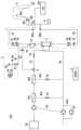
次に、第2の実施形態を説明する。第2の実施形態でも、慢性血液浄化療法として透析治療を行った後、返血工程を行う例を説明する。第2の実施形態は、第1の実施形態と比較して、返血工程のみが異なる。第2の実施形態に係る返血工程では、空気導入部3が血液回路1に空気を直接導入する。図8は、第2の実施形態に係る血液浄化装置200の構成を示す配管図である。血液浄化装置200は、空気導入部3の構成が異なること、脱血側エアトラップチャンバ7aおよび返血側エアトラップチャンバ7bを更に含むことを除き、第1の実施形態に係る血液浄化装置100と同一の構成を有する。Second Embodiment
Next, a second embodiment will be described. In the second embodiment, an example in which a blood return process is performed after dialysis treatment as a chronic blood purification therapy will also be described. The second embodiment differs from the first embodiment only in the blood return process. In the blood return process according to the second embodiment, the
図8に示すように、脱血側エアトラップチャンバ7aは、脱血側回路1aに設けられ、返血側エアトラップチャンバ7bは、返血側回路1bに設けられる。脱血側エアトラップチャンバ7aは、透析治療などにおいて、血液ポンプP1を駆動することによって生じ得る空気が血液浄化器2に流入しないよう、空気を捕捉することを主な目的として設けられる。返血側エアトラップチャンバ7bは、上述した空気が血液回路1を通じて患者の体内に空気が流入しないように、空気を捕捉することを主な目的として設けられる。つまり、脱血側エアトラップチャンバ7aおよび返血側エアトラップチャンバ7bは共に、血液回路1内で血液を収容するチャンバとしての役割を果たす。As shown in FIG. 8, the blood removal side
空気導入部3(空気導入路3b)は、脱血側エアトラップチャンバ7aおよび返血側エアトラップチャンバ7bに接続され、脱血側エアトラップチャンバ7aおよび返血側エアトラップチャンバ7bに空気を導入する。脱血側エアトラップチャンバ7aおよび返血側エアトラップチャンバ7bはそれぞれ、血液層と空気層の2層になっており、チャンバ内に空気がたまると液面が下がり、血液浄化器2の中空糸に空気が入るエアロックが生じるおそれがある。The air introduction section 3 (
図8に示す例では、空気導入部3(空気ポンプ3a)は、正回転することによって、返血側エアトラップチャンバ7bに空気を導入して液面を下降させ、逆回転することによって、返血側エアトラップチャンバ7bから空気を排出して液面を上昇させる。同様に、空気導入部3(空気ポンプ3a)は、正回転することによって、脱血側エアトラップチャンバ7aに空気を導入して液面を下降させ、逆回転することによって、脱血側エアトラップチャンバ7aから空気を排出して液面を上昇させる。In the example shown in FIG. 8, the air introduction unit 3 (
空気導入部3は、開閉弁(電磁弁)3fを更に含む。開閉弁3fは、空気導入路3bと脱血側エアトラップチャンバ7aとの間に設けられる。開閉弁3fの開閉によって、空気導入部3から脱血側エアトラップチャンバ7aへの空気の流れが制御される(空気導入部3は、脱血側エアトラップチャンバ7aに空気を流動する)。開閉弁3cの開閉によって、空気導入部3から返血側エアトラップチャンバ7bへの空気の流れが制御される(空気導入部3は、返血側エアトラップチャンバ7bに空気を流動する)。The
空気導入部3は、透析治療などにおいては(つまり、返血工程以外では)、上述したように脱血側エアトラップチャンバ7aおよび返血側エアトラップチャンバ7bに対する液面調整ポンプとしての機能を果たす(液面調整ポンプは、通常は返血に使用されない)。一方で、空気導入部3は、返血工程では、血液回路1および血液浄化器2内の血液を体内に戻すために血液回路1に空気を導入する役割を果たす。In dialysis treatment and the like (i.e., other than the blood return process), the
なお、脱血側エアトラップチャンバ7aおよび返血側エアトラップチャンバ7bは必須の構成ではない。例えば、脱血側エアトラップチャンバ7aおよび返血側エアトラップチャンバ7bが設けられない場合、図9に示すように、空気導入部3は、返血側回路1bに接続されてもよく、図10に示すように、空気導入部3は、脱血側回路1aに接続されてもよい。また、脱血側エアトラップチャンバ7aおよび返血側エアトラップチャンバ7bは必ずしも両方が設けられる必要はなく、いずれかのみが設けられてもよい。The blood removal side
次に、図11乃至13を参照して、第2の実施形態に係る返血工程を説明する。第2の実施形態に係る返血工程では、図8で説明した構成において、最初に、血液回路1に透析液が導入され(透析液導入段階)、その後、血液回路1に空気が導入される(空気導入段階)。図11は、透析液導入段階を示す。図12は、空気導入部3が返血側回路1bに空気を導入する空気導入段階を示す。図13では、空気導入部3が脱血側回路1aに空気を導入する空気導入段階を示す。図12および図13に示す空気導入段階は、図11に示す透析液導入段階の後に、両者のいずれかが行われる。Next, the blood return process according to the second embodiment will be described with reference to Figs. 11 to 13. In the blood return process according to the second embodiment, in the configuration described in Fig. 8, first, dialysis fluid is introduced into the blood circuit 1 (dialysis fluid introduction stage), and then air is introduced into the blood circuit 1 (air introduction stage). Fig. 11 shows the dialysis fluid introduction stage. Fig. 12 shows the air introduction stage in which the
図11は、透析液導入段階での透析液の流れを示す。図12は、返血側回路1bに空気を導入する空気導入段階での透析液および空気の流れを示す。図13は、脱血側回路1aに空気を導入する空気導入段階での透析液および空気の流れを示す。以下の図において、開閉弁が開放している場合、図に示す開閉弁は網掛けで表示され、開閉弁が閉鎖している場合、図に示す開閉弁は白抜きで表示される。Figure 11 shows the flow of dialysis fluid at the dialysis fluid introduction stage. Figure 12 shows the flow of dialysis fluid and air at the air introduction stage where air is introduced into the blood
図11に示す透析液導入段階では、制御装置Cによる制御の下、開閉弁V4および開閉弁V2が開放する。また、血液ポンプP1が正回転する。更に、複式ポンプP2が駆動する。これによって、透析液供給部からの透析液は、透析液導入ラインIL、プライミング液ラインPL、脱血側回路1a、血液浄化器2、および返血側回路1bを通る。図11では、この透析液の流れを、太鎖線矢印で示している。この透析液の流れにより、透析液が血液浄化器2および血液回路1(返血側回路1b)に残存した血液を押し出し、血液が体内に戻される。このような状態で、予め定められた量の透析液が血液回路1を流れると、空気導入段階に切り替わる。In the dialysis fluid introduction stage shown in FIG. 11, the on-off valve V4 and the on-off valve V2 are opened under the control of the control device C. In addition, the blood pump P1 rotates forward. Furthermore, the duplex pump P2 is driven. As a result, the dialysis fluid from the dialysis fluid supply unit passes through the dialysis fluid introduction line IL, the priming fluid line PL, the blood
図12に示す返血側回路1bに空気を導入する空気導入段階に切り替わると、制御装置Cによる制御の下、開閉弁V4が閉鎖し、血液ポンプP1および複式ポンプP2が駆動を停止する。代わりに、開閉弁3cが開放する。また、空気ポンプ3aが駆動する。これによって、空気は、空気導入路3bおよび返血側回路1bを通る。図12では、この空気の流れを、太実線矢印で示している。この空気の流れにより、透析液導入段階において血液回路1に導入された透析液を介して、血液回路1に残存した血液を押し出し、血液が体内に戻される。When the system switches to the air introduction stage in which air is introduced into the blood
図13に示す脱血側回路1aに空気を導入する空気導入段階に切り替わると、制御装置Cによる制御の下、開閉弁V4および開閉弁3cが閉鎖し、複式ポンプP2が駆動を停止する。代わりに、開閉弁3fが開放する。また、空気ポンプ3aが駆動する。これによって、空気は、空気導入路3b、脱血側回路1a、血液浄化器2、および返血側回路1bを通る。図13では、この空気の流れを、太実線矢印で示している。この空気の流れにより、透析液導入段階において血液回路1に導入された透析液を介して、血液浄化器2および血液回路1に残存した血液を押し出し、血液が体内に戻される。When the system switches to the air introduction stage in which air is introduced into the blood
図13に示した構成では、空気導入部3が脱血側エアトラップチャンバ7aに接続され、空気導入部3が血液回路1に空気を導入するが、血液ポンプP1が空気導入部3の役割を果たしてもよい。空気ポンプP1は、透析液導入段階においてプライミング液ラインPLから導入された全ての透析液が空気ポンプP1を通った後も正回転を続けると、返血側回路1bに空気を導入することになる。よって、この場合、空気導入部3は設けられなくてもよい。In the configuration shown in FIG. 13, the
上述したように、空気導入部3は、透析治療のときに液面調整ポンプとしての役割を果たすと共に、返血工程では、返血のために血液回路1に空気を導入する役割を果たす。血液ポンプP1は、透析液を血液回路1内で送液する役割を果たすと共に、返血工程の空気導入段階では、返血のために血液回路1に空気を導入する役割を果たす。As described above, the
なお、第2の実施形態における透析液導入段階終了条件および返血工程終了条件は、第1の実施形態で説明した条件と同様である。また、血液ポンプP1についての状態モードの遷移を行う処理についても第1の実施形態で説明した処理と同様である。The conditions for ending the dialysis fluid introduction stage and the blood return process in the second embodiment are the same as those described in the first embodiment. The process for changing the state mode of the blood pump P1 is also the same as that described in the first embodiment.
以上のように、第2の実施形態に係る血液浄化装置200を説明した。第2の実施形態でも、穿刺針が抜針されないままの状態で、排液工程などが開始することを防止することができると共に、透析液のみを使用して返血を行う場合と比較して、返血に使用する透析液の量を減少させることができる。As described above, the
<第3の実施形態>
次に、第3の実施形態を説明する。第3の実施形態では、主に、急性血液浄化療法として、急性疾患に対して病気の原因物質を除去するアフェレシス療法を行った後、返血工程を行う例を説明する。なお、急性血液浄化療法として、アフェレシス療法は例示にすぎず、本実施形態は、持続的腎代替療法(CRRT)および持続的腎代替療法(IRRT)などにも適用されてもよい。Third Embodiment
Next, a third embodiment will be described. In the third embodiment, an example will be described in which, as acute blood purification therapy, apheresis therapy is performed to remove causative substances of an acute disease, followed by a blood return process. Note that apheresis therapy is merely an example of acute blood purification therapy, and this embodiment may also be applied to continuous renal replacement therapy (CRRT) and intravenous renal replacement therapy (IRRT), etc.
アフェレシス療法は、血液内の病原性物質を分離し除去するために、血漿交換などを行う治療法である。アフェレシス療法では、一時的血液浄化用バスキュラーアクセスとして、ダブルルーメンカテーテルを使用することがある。第3の実施形態は、第1の実施形態と比較して、ダブルルーメン構造を有する穿刺針が使用されることに伴い、抜針検出部の構造が異なる。よって、第3の実施形態では、抜針検出部および穿刺針の構成のみを説明する。本実施形態に示す抜針検出部および穿刺針の構成は、アフェレシス治療などの急性血液浄化療法に使用される急性血液浄化装置に適用されてもよい。Apheresis therapy is a treatment that performs procedures such as plasma exchange to separate and remove pathogenic substances from blood. In apheresis therapy, a double-lumen catheter may be used as a vascular access for temporary blood purification. In the third embodiment, the structure of the needle removal detection unit is different from that of the first embodiment due to the use of a puncture needle with a double lumen structure. Therefore, in the third embodiment, only the configuration of the needle removal detection unit and the puncture needle will be described. The configuration of the needle removal detection unit and the puncture needle shown in this embodiment may be applied to an acute blood purification device used in acute blood purification therapy such as apheresis treatment.
図14は、抜針検出部4および穿刺針Nの構成を示す図である。図14に示すように、患者Pの頸には穿刺針Nが穿刺される。穿刺針Nには、抜針検出部4が取り付けられ、抜針検出部4は、電源PSに接続される。穿刺針Nは、ダブルルーメン構造(ダブルルーメンカテーテルDLC)を有する。Figure 14 is a diagram showing the configuration of the needle
ダブルルーメンカテーテルDLCは主に、穿刺針N、ダブルルーメンチューブDLT、脱血側分岐部BA、および返血側分岐部BRを含む。ダブルルーメンカテーテルDLCは、1つの穿刺針Nから脱血側回路1aおよび返血側回路1bに分岐する構造を有する。ダブルルーメンチューブDLTの一端は、穿刺針Nに接続される。ダブルルーメンチューブDLTの他端は、脱血側分岐部BAおよび返血側分岐部BRに分岐する。脱血側分岐部BAは、脱血側回路1aに接続され、返血側分岐部BRは、返血側回路1bに接続される。なお、図14は、頸に穿刺される状態を示しているが、穿刺先はこれに限らず、大腿または鎖骨下などに穿刺してもよい。The double lumen catheter DLC mainly includes a puncture needle N, a double lumen tube DLT, a blood removal side branch BA, and a blood return side branch BR. The double lumen catheter DLC has a structure in which the blood
穿刺針Nは、翼部Wと一体となって形成される。翼部Wは、抜針検出部4が設けられる。抜針検出部4は、例えば、シート状のタッチセンサとして実装され、翼部Wに蒸着される。つまり、抜針検出部4は、穿刺針Nと一体化される。タッチセンサは、静電容量方式タッチセンサまたは抵抗膜方式タッチセンサなどであってもよい。抜針検出部4が静電容量方式タッチセンサとして実装される場合、患者Pに穿刺針Nが穿刺されている間は、電源PSがタッチセンサの電極に印加し、針が患者Pに接触することによって生じる静電容量(電荷)の変化を検出する。抜針検出部4が抵抗膜方式タッチセンサとして実装される場合、患者Pに穿刺針Nが穿刺されている間は、電源PSがタッチセンサの電極に印加し、針が患者Pに接触することによって生じる透明導電膜の抵抗値変化を検出する。The puncture needle N is formed integrally with the wing portion W. The wing portion W is provided with the needle
抜針検出部4は、上述したいずれかの方式において、静電容量の変化または透明導電膜の抵抗値変化を検出することによって、穿刺針Nが患者Pに穿刺されているか否かを検出することができる。つまり、抜針検出部4は、タッチセンサが患者の体表面に対する穿刺針Nの接触状態を検出することによって、患者Pから穿刺針Nが抜針されたことを検出することができる。なお、抜針検出部4は、上述した静電容量値または抵抗値を制御装置Cに送信し、制御装置Cがその値の変化に基づいて抜針がされたと判定する。このようにして、抜針検出部4は、ダブルルーメンカテーテルDLCなどの、患者Pに穿刺する穿刺針が単針である場合も、抜針がされたことを検出することができる。The needle
上記説明した抜針検出部4の構成によって、患者Pから穿刺針Nが抜針されたことを検出する。第3の実施形態における透析液導入段階終了条件および返血工程終了条件も、第1の実施形態で説明した条件と同様である。また、血液ポンプP1についての状態モードの遷移を行う処理についても第1の実施形態で説明した処理と同様である。さらに、第3の実施形態において、第2の実施形態で説明した返血工程が適用されてもよい。The needle
以上のように、第3の実施形態に係る血液浄化装置を説明した。第3の実施形態でも、穿刺針が抜針されないままの状態で、排液工程などが開始することを防止することができると共に、急性血液浄化療法においてダブルルーメンカテーテルなどの単針の穿刺針が使用される場合でも、穿刺針の抜針を検出することができる。As described above, the blood purification device according to the third embodiment has been described. In the third embodiment, it is possible to prevent the drainage process and the like from starting while the puncture needle is not removed, and it is also possible to detect the removal of the puncture needle even when a single puncture needle such as a double lumen catheter is used in acute blood purification therapy.
上記説明した実施形態は例示にすぎず、実施形態の範囲は、説明した例に限定されない。説明した処理および構成要素に加え、追加の処理および/または構成要素が追加されてもよい。また、発明の概念から逸脱することなく、説明した処理および/もしくは構成要素に変更が加えられてもよく、または特定の処理および/もしくは構成要素が省略されてもよい。さらに、説明した処理の順序は変更されてもよい。The above-described embodiments are merely illustrative, and the scope of the embodiments is not limited to the described examples. In addition to the described processes and components, additional processes and/or components may be added. Also, changes may be made to the described processes and/or components, or certain processes and/or components may be omitted, without departing from the inventive concept. Furthermore, the order of the described processes may be changed.
また、実施形態に係る血液浄化装置は、制御装置Cによって実行されるコンピュータプログラムによって実装されるが、当該コンピュータプログラムは、非一時的記憶媒体に記憶されてもよい。非一時的記憶媒体の例は、リードオンリメモリ(ROM)、ランダムアクセスメモリ(RAM)、レジスタ、キャッシュメモリ、半導体メモリ装置、内蔵ハードディスクおよび取外可能ディスク装置などの磁気媒体、光磁気媒体、ならびにCD-ROMディスクおよびデジタル多用途ディスク(DVD)などの光学媒体などを含む。The blood purification device according to the embodiment is implemented by a computer program executed by the control device C, and the computer program may be stored in a non-transitory storage medium. Examples of non-transitory storage media include read-only memory (ROM), random access memory (RAM), registers, cache memory, semiconductor memory devices, magnetic media such as internal hard disks and removable disk devices, magneto-optical media, and optical media such as CD-ROM disks and digital versatile disks (DVDs).
1 血液回路
1a 脱血側回路
1b 返血側回路
2 血液浄化器
3 空気導入部
3a 空気ポンプ
3b 空気導入路
3c 開閉弁
3d 空気フィルタ
3e 空気フィルタ
3f 開閉弁
4 抜針検出部
5、5a、5b 血液濃淡検出部
6、6a、6b 気泡検出部
7a 脱血側エアトラップチャンバ
7b 返血側エアトラップチャンバ
100 血液浄化装置
200 血液浄化装置
IL 透析液導入ライン
EL 排液ライン
PL プライミング液ライン
P1 血液ポンプ
P2 透析液ポンプ
P3 排液ポンプ
P 透析液ポート
V1~V6 開閉弁
EPa 電極
EPb 電極
EPc 電極
IA インピーダンス調整回路
A1 差動増幅回路
A2 差動増幅回路
R 整流回路
HF 高域遮断フィルタ
N 穿刺針
W 翼部
RN 脱血側穿刺針
AN 返血側穿刺針
DLC ダブルルーメンカテーテル
DLT ダブルルーメンチューブ
BA 脱血側分岐部
BR 返血側分岐部
C 制御装置
PS 電源 1
Claims (12)
Translated fromJapanese前記血液回路に設けられ、駆動することによって前記血液回路内の液体を送液する血液ポンプと、
前記患者から前記穿刺針が抜針されたことを検出する抜針検出部と、
前記血液回路内の血液を患者に戻す返血工程を開始させ、前記返血工程が終了したと判定したことに応答して、前記血液ポンプを非活性状態にする、制御装置と、
を備え、
前記返血工程は、前記血液回路に透析液を導入する透析液導入段階と、前記透析液導入段階の後に前記血液回路に空気を導入する空気導入段階とを含み、
前記制御装置は、返血量および/または経過時間に基づいて、前記透析液導入段階を終了させるか否かを判定し、前記透析液導入段階が終了したと判定したことに応答して、前記空気導入段階を開始させる、
血液浄化装置。 a blood circuit connected to the puncture needle inserted into the patient and through which blood from the patient flows;
a blood pump provided in the blood circuit and configured to pump liquid in the blood circuit by being driven;
a needle removal detection unit that detects when the puncture needle is removed from the patient;
a control device that starts a blood return process for returning blood in the blood circuit to a patient, and deactivates the blood pump in response to determining that the blood return process has been completed;
Equipped with
the blood returning step includes a dialysis fluid introducing step of introducing a dialysis fluid into the blood circuit, and an air introducing step of introducing air into the blood circuit after the dialysis fluid introducing step,
The control device determines whether or not to terminate the dialysate introduction step based on the amount of returned blood and/or the elapsed time, and starts the air introduction step in response to determining that the dialysate introduction step has ended.
Blood purification device.
前記返血工程において、前記血液回路に空気を導入して、前記血液回路に導入された透析液を押し出す空気導入部と、
を更に備える、請求項1に記載の血液浄化装置。 a dialysis fluid introduction circuit for introducing a dialysis fluid into the blood circuit in the blood returning step;
an air introduction section that introduces air into the blood circuit in the blood return step to push out the dialysis fluid introduced into the blood circuit;
The blood purification apparatus according to claim 1 , further comprising:
前記空気導入部は、前記チャンバに接続され、前記返血工程以外では、前記チャンバに空気を流動することによって前記チャンバ内の液面を調整する、
請求項8に記載の血液浄化装置。 A chamber is provided in the blood circuit to accommodate blood in the blood circuit,
the air introduction section is connected to the chamber, and adjusts the liquid level in the chamber by flowing air into the chamber during a period other than the blood return process.
The blood purification apparatus according to claim 8.
前記血液ポンプは、前記チャンバに接続され、前記返血工程では、前記空気導入部として前記チャンバに空気を導入する、
請求項8に記載の血液浄化装置。 A chamber is provided in the blood circuit to accommodate blood in the blood circuit,
the blood pump is connected to the chamber, and in the blood return process, the blood pump serves as the air introduction section to introduce air into the chamber.
The blood purification apparatus according to claim 8.
前記血液回路に設けられ、駆動することによって前記血液回路内の液体を送液する血液ポンプと、
前記患者から前記穿刺針が抜針されたことを検出する抜針検出部と、
を含む血液浄化装置の作動方法であって、
前記血液浄化装置が、
前記血液回路に透析液を導入する透析液導入段階を実行するよう前記血液ポンプを制御するステップと、
返血量および/または経過時間に基づいて、前記透析液導入段階を終了させるか否かを判定するステップと、
前記透析液導入段階が終了したと判定したことに応答して、前記血液回路に空気を導入する空気導入段階を開始するステップと、
前記空気導入段階が終了したと判定した後、前記穿刺針が抜針されたことを検出するまで、前記血液ポンプを非活性状態にするステップと、
を備える方法。a blood circuit connected to the puncture needle insertedinto the patient and through which blood from the patient flows;
a blood pump provided in the blood circuit and configured to pump liquid in the blood circuit by being driven;
a needle removal detection unit that detects when the puncture needle is removed from the patient;
A method for operating a blood purification device, comprising :
The blood purification device comprises:
controllingthe blood pump to perform a dialysate introduction step of introducing dialysate into the blood circuit;
determining whether to terminate the dialysate introduction step based on the amount of blood returned and/or the elapsed time;
initiating an air introduction step ofintroducing air into the blood circuit in response to determining that the dialysate introduction step has ended;
After determining thatthe air introduction step is completed, deactivating the blood pump until it is detected that the puncture needle has been removed;
A method for providing the above.
Priority Applications (5)
| Application Number | Priority Date | Filing Date | Title |
|---|---|---|---|
| JP2020189213AJP7536608B2 (en) | 2020-11-13 | 2020-11-13 | Blood Purification Device |
| US18/033,825US20230398277A1 (en) | 2020-11-13 | 2021-07-27 | Blood purification apparatus |
| CN202180075008.2ACN116419768B (en) | 2020-11-13 | 2021-07-27 | Blood purifying device |
| EP21891422.4AEP4245329A4 (en) | 2020-11-13 | 2021-07-27 | BLOOD PURIFYING DEVICE |
| PCT/JP2021/027726WO2022102174A1 (en) | 2020-11-13 | 2021-07-27 | Blood purification device |
Applications Claiming Priority (1)
| Application Number | Priority Date | Filing Date | Title |
|---|---|---|---|
| JP2020189213AJP7536608B2 (en) | 2020-11-13 | 2020-11-13 | Blood Purification Device |
Publications (3)
| Publication Number | Publication Date |
|---|---|
| JP2022078501A JP2022078501A (en) | 2022-05-25 |
| JP2022078501A5 JP2022078501A5 (en) | 2023-10-03 |
| JP7536608B2true JP7536608B2 (en) | 2024-08-20 |
Family
ID=81601042
Family Applications (1)
| Application Number | Title | Priority Date | Filing Date |
|---|---|---|---|
| JP2020189213AActiveJP7536608B2 (en) | 2020-11-13 | 2020-11-13 | Blood Purification Device |
Country Status (5)
| Country | Link |
|---|---|
| US (1) | US20230398277A1 (en) |
| EP (1) | EP4245329A4 (en) |
| JP (1) | JP7536608B2 (en) |
| CN (1) | CN116419768B (en) |
| WO (1) | WO2022102174A1 (en) |
Families Citing this family (1)
| Publication number | Priority date | Publication date | Assignee | Title |
|---|---|---|---|---|
| JP2024004226A (en)* | 2022-06-28 | 2024-01-16 | 日機装株式会社 | blood purification device |
Citations (4)
| Publication number | Priority date | Publication date | Assignee | Title |
|---|---|---|---|---|
| JP2007020801A (en) | 2005-07-14 | 2007-02-01 | Nikkiso Co Ltd | Puncture monitoring device |
| JP2010269050A (en) | 2009-05-25 | 2010-12-02 | Nikkiso Co Ltd | Blood purification equipment |
| JP2013039241A (en) | 2011-08-17 | 2013-02-28 | Nikkiso Co Ltd | Blood purification apparatus |
| JP2016165401A (en) | 2015-03-10 | 2016-09-15 | 日機装株式会社 | Blood purification equipment |
Family Cites Families (10)
| Publication number | Priority date | Publication date | Assignee | Title |
|---|---|---|---|---|
| JP2003180823A (en)* | 2001-12-18 | 2003-07-02 | Kita Kyushu Biophysics Kenkyusho:Kk | Automatic hemodialysis instrument |
| US8029454B2 (en)* | 2003-11-05 | 2011-10-04 | Baxter International Inc. | High convection home hemodialysis/hemofiltration and sorbent system |
| JP4989069B2 (en)* | 2005-12-19 | 2012-08-01 | 株式会社ジェイ・エム・エス | Automatic hemodialysis machine |
| US8357298B2 (en)* | 2007-02-27 | 2013-01-22 | Deka Products Limited Partnership | Hemodialysis systems and methods |
| JP5693890B2 (en)* | 2010-08-05 | 2015-04-01 | 日機装株式会社 | Blood purification equipment |
| DE102011108785A1 (en)* | 2011-07-29 | 2013-01-31 | Fresenius Medical Care Deutschland Gmbh | A method of removing fluid from a blood filter after completion of a blood treatment session and a treatment device for performing the same |
| JP5934581B2 (en)* | 2012-06-04 | 2016-06-15 | 東レ・メディカル株式会社 | Blood purification equipment |
| JP6545485B2 (en)* | 2015-03-10 | 2019-07-17 | 日機装株式会社 | Blood purification device |
| JP6998112B2 (en)* | 2016-09-12 | 2022-01-18 | 日機装株式会社 | Blood purification device |
| JP7184341B2 (en)* | 2019-02-28 | 2022-12-06 | 学校法人常翔学園 | Needle removal detection method and extracorporeal blood circulation device using the method |
- 2020
- 2020-11-13JPJP2020189213Apatent/JP7536608B2/enactiveActive
- 2021
- 2021-07-27USUS18/033,825patent/US20230398277A1/enactivePending
- 2021-07-27CNCN202180075008.2Apatent/CN116419768B/enactiveActive
- 2021-07-27EPEP21891422.4Apatent/EP4245329A4/enactivePending
- 2021-07-27WOPCT/JP2021/027726patent/WO2022102174A1/ennot_activeCeased
Patent Citations (4)
| Publication number | Priority date | Publication date | Assignee | Title |
|---|---|---|---|---|
| JP2007020801A (en) | 2005-07-14 | 2007-02-01 | Nikkiso Co Ltd | Puncture monitoring device |
| JP2010269050A (en) | 2009-05-25 | 2010-12-02 | Nikkiso Co Ltd | Blood purification equipment |
| JP2013039241A (en) | 2011-08-17 | 2013-02-28 | Nikkiso Co Ltd | Blood purification apparatus |
| JP2016165401A (en) | 2015-03-10 | 2016-09-15 | 日機装株式会社 | Blood purification equipment |
Also Published As
| Publication number | Publication date |
|---|---|
| CN116419768A (en) | 2023-07-11 |
| EP4245329A1 (en) | 2023-09-20 |
| CN116419768B (en) | 2025-09-19 |
| US20230398277A1 (en) | 2023-12-14 |
| WO2022102174A1 (en) | 2022-05-19 |
| EP4245329A4 (en) | 2024-10-16 |
| JP2022078501A (en) | 2022-05-25 |
Similar Documents
| Publication | Publication Date | Title |
|---|---|---|
| US20130150768A1 (en) | Blood Purification Apparatus And Method For Inspecting Liquid Leakage Thereof | |
| JP5259159B2 (en) | Chemical treatment flow control system and method | |
| JP6283363B2 (en) | Device and method for detecting recirculation during extracorporeal blood treatment | |
| US11964089B2 (en) | Blood purification apparatus and method of trapping bubbles therein | |
| JP2019055267A (en) | Blood purification device and priming method thereof | |
| JP4333840B2 (en) | Devices for internal and external purification | |
| JP2000107283A (en) | Dialysis apparatus and washing priming method | |
| US10610634B2 (en) | Blood purification apparatus | |
| CN103732270A (en) | Blood purification device | |
| US11554202B2 (en) | Blood purification apparatus and method of discharging bubbles therefrom | |
| JP7536608B2 (en) | Blood Purification Device | |
| JP6642695B2 (en) | Hemodialysis machine and control program | |
| CN112969484B (en) | Blood purifying device | |
| CN110799225A (en) | Device for extracorporeal blood therapy and device for collecting blood clots and method for determining hemodynamic parameters during extracorporeal blood therapy | |
| CN110740769A (en) | Device for extracorporeal blood treatment and method for determining hemodynamic parameters during extracorporeal blood treatment | |
| JP7293761B2 (en) | Determining method for dialysis machine and circuit set | |
| CN103906538A (en) | Blood purification device | |
| JP7422928B1 (en) | blood purification device | |
| JP7445827B1 (en) | blood purification device | |
| JP7292331B2 (en) | blood purifier | |
| CN112312940A (en) | Blood purification device and plasma flow acquisition method of blood purification device | |
| WO2023032960A1 (en) | Blood purification device | |
| CN119451717A (en) | Blood purification device |
Legal Events
| Date | Code | Title | Description |
|---|---|---|---|
| A521 | Request for written amendment filed | Free format text:JAPANESE INTERMEDIATE CODE: A523 Effective date:20230925 | |
| A621 | Written request for application examination | Free format text:JAPANESE INTERMEDIATE CODE: A621 Effective date:20230925 | |
| A131 | Notification of reasons for refusal | Free format text:JAPANESE INTERMEDIATE CODE: A131 Effective date:20240402 | |
| A521 | Request for written amendment filed | Free format text:JAPANESE INTERMEDIATE CODE: A523 Effective date:20240529 | |
| TRDD | Decision of grant or rejection written | ||
| A01 | Written decision to grant a patent or to grant a registration (utility model) | Free format text:JAPANESE INTERMEDIATE CODE: A01 Effective date:20240730 | |
| A61 | First payment of annual fees (during grant procedure) | Free format text:JAPANESE INTERMEDIATE CODE: A61 Effective date:20240807 | |
| R150 | Certificate of patent or registration of utility model | Ref document number:7536608 Country of ref document:JP Free format text:JAPANESE INTERMEDIATE CODE: R150 |