JP7535159B2 - A cardiovascular support system that quantifies cardiac function and promotes cardiac recovery - Google Patents
A cardiovascular support system that quantifies cardiac function and promotes cardiac recoveryDownload PDFInfo
- Publication number
- JP7535159B2 JP7535159B2JP2023109687AJP2023109687AJP7535159B2JP 7535159 B2JP7535159 B2JP 7535159B2JP 2023109687 AJP2023109687 AJP 2023109687AJP 2023109687 AJP2023109687 AJP 2023109687AJP 7535159 B2JP7535159 B2JP 7535159B2
- Authority
- JP
- Japan
- Prior art keywords
- cardiac
- pressure
- motor
- heart
- parameter
- Prior art date
- Legal status (The legal status is an assumption and is not a legal conclusion. Google has not performed a legal analysis and makes no representation as to the accuracy of the status listed.)
- Active
Links
- 230000000747cardiac effectEffects0.000titleclaimsdescription476
- 230000004217heart functionEffects0.000titleclaimsdescription91
- 238000011084recoveryMethods0.000titleclaimsdescription25
- 230000002526effect on cardiovascular systemEffects0.000titledescription27
- 210000002216heartAnatomy0.000claimsdescription250
- 230000002861ventricularEffects0.000claimsdescription76
- 230000008859changeEffects0.000claimsdescription57
- 230000000004hemodynamic effectEffects0.000claimsdescription56
- 239000008280bloodSubstances0.000claimsdescription42
- 210000004369bloodAnatomy0.000claimsdescription42
- 210000005242cardiac chamberAnatomy0.000claimsdescription24
- 230000036316preloadEffects0.000claimsdescription24
- 210000001765aortic valveAnatomy0.000claimsdescription13
- 238000000034methodMethods0.000description85
- 230000006870functionEffects0.000description56
- 230000003205diastolic effectEffects0.000description52
- 238000005259measurementMethods0.000description50
- 210000000709aortaAnatomy0.000description46
- 210000005240left ventricleAnatomy0.000description42
- 238000004422calculation algorithmMethods0.000description41
- 239000000523sampleSubstances0.000description35
- 238000010171animal modelMethods0.000description23
- 230000008569processEffects0.000description23
- 230000007423decreaseEffects0.000description18
- 230000017531blood circulationEffects0.000description15
- 230000004044responseEffects0.000description12
- 206010019280Heart failuresDiseases0.000description11
- 238000004364calculation methodMethods0.000description11
- 238000012512characterization methodMethods0.000description10
- 230000000694effectsEffects0.000description10
- 208000010125myocardial infarctionDiseases0.000description10
- 238000002560therapeutic procedureMethods0.000description10
- 239000002876beta blockerSubstances0.000description9
- 229940097320beta blocking agentDrugs0.000description9
- 230000036772blood pressureEffects0.000description9
- 230000008602contractionEffects0.000description9
- 230000003247decreasing effectEffects0.000description9
- 238000004590computer programMethods0.000description8
- 210000001147pulmonary arteryAnatomy0.000description8
- 238000000718qrs complexMethods0.000description8
- 238000005070samplingMethods0.000description8
- 210000005166vasculatureAnatomy0.000description8
- 241001465754MetazoaSpecies0.000description7
- 238000001514detection methodMethods0.000description7
- 238000012545processingMethods0.000description7
- 210000001631vena cava inferiorAnatomy0.000description7
- 238000009530blood pressure measurementMethods0.000description6
- 230000006866deteriorationEffects0.000description6
- 238000011156evaluationMethods0.000description6
- 239000012530fluidSubstances0.000description6
- 238000012544monitoring processMethods0.000description6
- 230000000541pulsatile effectEffects0.000description6
- 238000005086pumpingMethods0.000description6
- 230000011218segmentationEffects0.000description6
- 230000009471actionEffects0.000description5
- 230000002542deteriorative effectEffects0.000description5
- 230000035487diastolic blood pressureEffects0.000description5
- 210000000056organAnatomy0.000description5
- 238000010200validation analysisMethods0.000description5
- 238000013459approachMethods0.000description4
- 230000009286beneficial effectEffects0.000description4
- 210000000748cardiovascular systemAnatomy0.000description4
- 230000004087circulationEffects0.000description4
- 239000003550markerSubstances0.000description4
- 230000007170pathologyEffects0.000description4
- 230000035945sensitivityEffects0.000description4
- 238000011282treatmentMethods0.000description4
- 238000004458analytical methodMethods0.000description3
- 230000008878couplingEffects0.000description3
- 238000010168coupling processMethods0.000description3
- 238000005859coupling reactionMethods0.000description3
- 201000010099diseaseDiseases0.000description3
- 208000037265diseases, disorders, signs and symptomsDiseases0.000description3
- 239000000284extractSubstances0.000description3
- 230000010247heart contractionEffects0.000description3
- 238000003780insertionMethods0.000description3
- 230000037431insertionEffects0.000description3
- 238000013507mappingMethods0.000description3
- 238000012986modificationMethods0.000description3
- 230000004048modificationEffects0.000description3
- 230000003287optical effectEffects0.000description3
- 239000000047productSubstances0.000description3
- 230000002685pulmonary effectEffects0.000description3
- 230000010349pulsationEffects0.000description3
- 230000035485pulse pressureEffects0.000description3
- 230000000241respiratory effectEffects0.000description3
- 230000007704transitionEffects0.000description3
- 208000032456Hemorrhagic ShockDiseases0.000description2
- 206010049771Shock haemorrhagicDiseases0.000description2
- 241000282887SuidaeSpecies0.000description2
- 206010000891acute myocardial infarctionDiseases0.000description2
- 230000006399behaviorEffects0.000description2
- 230000005189cardiac healthEffects0.000description2
- 238000004891communicationMethods0.000description2
- 125000004122cyclic groupChemical group0.000description2
- 208000028867ischemiaDiseases0.000description2
- 230000004660morphological changeEffects0.000description2
- 238000011328necessary treatmentMethods0.000description2
- 230000000644propagated effectEffects0.000description2
- 238000013515scriptMethods0.000description2
- 230000035939shockEffects0.000description2
- 230000002792vascularEffects0.000description2
- 238000012935AveragingMethods0.000description1
- 206010020880HypertrophyDiseases0.000description1
- 208000002847Surgical WoundDiseases0.000description1
- 230000001154acute effectEffects0.000description1
- 210000003484anatomyAnatomy0.000description1
- 238000003491arrayMethods0.000description1
- 230000004872arterial blood pressureEffects0.000description1
- 210000004191axillary arteryAnatomy0.000description1
- 230000008901benefitEffects0.000description1
- 230000002457bidirectional effectEffects0.000description1
- 230000002146bilateral effectEffects0.000description1
- 230000005540biological transmissionEffects0.000description1
- 210000004204blood vesselAnatomy0.000description1
- 238000011088calibration curveMethods0.000description1
- 210000004903cardiac systemAnatomy0.000description1
- 229940030602cardiac therapy drugDrugs0.000description1
- 230000001684chronic effectEffects0.000description1
- 238000007796conventional methodMethods0.000description1
- 210000004351coronary vesselAnatomy0.000description1
- 238000013461designMethods0.000description1
- 238000011161developmentMethods0.000description1
- 230000018109developmental processEffects0.000description1
- 230000010339dilationEffects0.000description1
- 239000006185dispersionSubstances0.000description1
- 238000006073displacement reactionMethods0.000description1
- 239000003814drugSubstances0.000description1
- 230000005672electromagnetic fieldEffects0.000description1
- 238000002618extracorporeal membrane oxygenationMethods0.000description1
- 210000001105femoral arteryAnatomy0.000description1
- 230000006872improvementEffects0.000description1
- 239000004041inotropic agentSubstances0.000description1
- 238000007914intraventricular administrationMethods0.000description1
- 210000005246left atriumAnatomy0.000description1
- 230000009347mechanical transmissionEffects0.000description1
- 238000002324minimally invasive surgeryMethods0.000description1
- 239000000203mixtureSubstances0.000description1
- 238000005457optimizationMethods0.000description1
- 230000008816organ damageEffects0.000description1
- 238000000611regression analysisMethods0.000description1
- 238000012552reviewMethods0.000description1
- 210000005245right atriumAnatomy0.000description1
- 210000005241right ventricleAnatomy0.000description1
- 239000007787solidSubstances0.000description1
- 238000006467substitution reactionMethods0.000description1
- 239000000758substrateSubstances0.000description1
- 239000013589supplementSubstances0.000description1
- 238000012546transferMethods0.000description1
- 238000002054transplantationMethods0.000description1
- 230000032258transportEffects0.000description1
- 238000002604ultrasonographyMethods0.000description1
- 210000002620vena cava superiorAnatomy0.000description1
- 230000000007visual effectEffects0.000description1
Images


Classifications
- A—HUMAN NECESSITIES
- A61—MEDICAL OR VETERINARY SCIENCE; HYGIENE
- A61B—DIAGNOSIS; SURGERY; IDENTIFICATION
- A61B5/00—Measuring for diagnostic purposes; Identification of persons
- A61B5/02—Detecting, measuring or recording for evaluating the cardiovascular system, e.g. pulse, heart rate, blood pressure or blood flow
- A61B5/021—Measuring pressure in heart or blood vessels
- A61B5/02141—Details of apparatus construction, e.g. pump units or housings therefor, cuff pressurising systems, arrangements of fluid conduits or circuits
- A—HUMAN NECESSITIES
- A61—MEDICAL OR VETERINARY SCIENCE; HYGIENE
- A61B—DIAGNOSIS; SURGERY; IDENTIFICATION
- A61B5/00—Measuring for diagnostic purposes; Identification of persons
- A61B5/02—Detecting, measuring or recording for evaluating the cardiovascular system, e.g. pulse, heart rate, blood pressure or blood flow
- A61B5/02028—Determining haemodynamic parameters not otherwise provided for, e.g. cardiac contractility or left ventricular ejection fraction
- A—HUMAN NECESSITIES
- A61—MEDICAL OR VETERINARY SCIENCE; HYGIENE
- A61B—DIAGNOSIS; SURGERY; IDENTIFICATION
- A61B5/00—Measuring for diagnostic purposes; Identification of persons
- A61B5/02—Detecting, measuring or recording for evaluating the cardiovascular system, e.g. pulse, heart rate, blood pressure or blood flow
- A61B5/0205—Simultaneously evaluating both cardiovascular conditions and different types of body conditions, e.g. heart and respiratory condition
- A—HUMAN NECESSITIES
- A61—MEDICAL OR VETERINARY SCIENCE; HYGIENE
- A61B—DIAGNOSIS; SURGERY; IDENTIFICATION
- A61B5/00—Measuring for diagnostic purposes; Identification of persons
- A61B5/02—Detecting, measuring or recording for evaluating the cardiovascular system, e.g. pulse, heart rate, blood pressure or blood flow
- A61B5/021—Measuring pressure in heart or blood vessels
- A61B5/0215—Measuring pressure in heart or blood vessels by means inserted into the body
- A61B5/02158—Measuring pressure in heart or blood vessels by means inserted into the body provided with two or more sensor elements
- A—HUMAN NECESSITIES
- A61—MEDICAL OR VETERINARY SCIENCE; HYGIENE
- A61B—DIAGNOSIS; SURGERY; IDENTIFICATION
- A61B5/00—Measuring for diagnostic purposes; Identification of persons
- A61B5/02—Detecting, measuring or recording for evaluating the cardiovascular system, e.g. pulse, heart rate, blood pressure or blood flow
- A61B5/026—Measuring blood flow
- A61B5/029—Measuring blood output from the heart, e.g. minute volume
- A—HUMAN NECESSITIES
- A61—MEDICAL OR VETERINARY SCIENCE; HYGIENE
- A61B—DIAGNOSIS; SURGERY; IDENTIFICATION
- A61B5/00—Measuring for diagnostic purposes; Identification of persons
- A61B5/24—Detecting, measuring or recording bioelectric or biomagnetic signals of the body or parts thereof
- A61B5/316—Modalities, i.e. specific diagnostic methods
- A61B5/318—Heart-related electrical modalities, e.g. electrocardiography [ECG]
- A61B5/346—Analysis of electrocardiograms
- A61B5/349—Detecting specific parameters of the electrocardiograph cycle
- A61B5/352—Detecting R peaks, e.g. for synchronising diagnostic apparatus; Estimating R-R interval
- A—HUMAN NECESSITIES
- A61—MEDICAL OR VETERINARY SCIENCE; HYGIENE
- A61B—DIAGNOSIS; SURGERY; IDENTIFICATION
- A61B5/00—Measuring for diagnostic purposes; Identification of persons
- A61B5/48—Other medical applications
- A61B5/4848—Monitoring or testing the effects of treatment, e.g. of medication
- A—HUMAN NECESSITIES
- A61—MEDICAL OR VETERINARY SCIENCE; HYGIENE
- A61B—DIAGNOSIS; SURGERY; IDENTIFICATION
- A61B5/00—Measuring for diagnostic purposes; Identification of persons
- A61B5/72—Signal processing specially adapted for physiological signals or for diagnostic purposes
- A61B5/7271—Specific aspects of physiological measurement analysis
- A61B5/7275—Determining trends in physiological measurement data; Predicting development of a medical condition based on physiological measurements, e.g. determining a risk factor
- A—HUMAN NECESSITIES
- A61—MEDICAL OR VETERINARY SCIENCE; HYGIENE
- A61M—DEVICES FOR INTRODUCING MEDIA INTO, OR ONTO, THE BODY; DEVICES FOR TRANSDUCING BODY MEDIA OR FOR TAKING MEDIA FROM THE BODY; DEVICES FOR PRODUCING OR ENDING SLEEP OR STUPOR
- A61M60/00—Blood pumps; Devices for mechanical circulatory actuation; Balloon pumps for circulatory assistance
- A61M60/10—Location thereof with respect to the patient's body
- A61M60/104—Extracorporeal pumps, i.e. the blood being pumped outside the patient's body
- A61M60/117—Extracorporeal pumps, i.e. the blood being pumped outside the patient's body for assisting the heart, e.g. transcutaneous or external ventricular assist devices
- A—HUMAN NECESSITIES
- A61—MEDICAL OR VETERINARY SCIENCE; HYGIENE
- A61M—DEVICES FOR INTRODUCING MEDIA INTO, OR ONTO, THE BODY; DEVICES FOR TRANSDUCING BODY MEDIA OR FOR TAKING MEDIA FROM THE BODY; DEVICES FOR PRODUCING OR ENDING SLEEP OR STUPOR
- A61M60/00—Blood pumps; Devices for mechanical circulatory actuation; Balloon pumps for circulatory assistance
- A61M60/10—Location thereof with respect to the patient's body
- A61M60/122—Implantable pumps or pumping devices, i.e. the blood being pumped inside the patient's body
- A61M60/126—Implantable pumps or pumping devices, i.e. the blood being pumped inside the patient's body implantable via, into, inside, in line, branching on, or around a blood vessel
- A61M60/13—Implantable pumps or pumping devices, i.e. the blood being pumped inside the patient's body implantable via, into, inside, in line, branching on, or around a blood vessel by means of a catheter allowing explantation, e.g. catheter pumps temporarily introduced via the vascular system
- A—HUMAN NECESSITIES
- A61—MEDICAL OR VETERINARY SCIENCE; HYGIENE
- A61M—DEVICES FOR INTRODUCING MEDIA INTO, OR ONTO, THE BODY; DEVICES FOR TRANSDUCING BODY MEDIA OR FOR TAKING MEDIA FROM THE BODY; DEVICES FOR PRODUCING OR ENDING SLEEP OR STUPOR
- A61M60/00—Blood pumps; Devices for mechanical circulatory actuation; Balloon pumps for circulatory assistance
- A61M60/10—Location thereof with respect to the patient's body
- A61M60/122—Implantable pumps or pumping devices, i.e. the blood being pumped inside the patient's body
- A61M60/165—Implantable pumps or pumping devices, i.e. the blood being pumped inside the patient's body implantable in, on, or around the heart
- A61M60/178—Implantable pumps or pumping devices, i.e. the blood being pumped inside the patient's body implantable in, on, or around the heart drawing blood from a ventricle and returning the blood to the arterial system via a cannula external to the ventricle, e.g. left or right ventricular assist devices
- A—HUMAN NECESSITIES
- A61—MEDICAL OR VETERINARY SCIENCE; HYGIENE
- A61M—DEVICES FOR INTRODUCING MEDIA INTO, OR ONTO, THE BODY; DEVICES FOR TRANSDUCING BODY MEDIA OR FOR TAKING MEDIA FROM THE BODY; DEVICES FOR PRODUCING OR ENDING SLEEP OR STUPOR
- A61M60/00—Blood pumps; Devices for mechanical circulatory actuation; Balloon pumps for circulatory assistance
- A61M60/20—Type thereof
- A61M60/205—Non-positive displacement blood pumps
- A61M60/216—Non-positive displacement blood pumps including a rotating member acting on the blood, e.g. impeller
- A61M60/221—Non-positive displacement blood pumps including a rotating member acting on the blood, e.g. impeller the blood flow through the rotating member having both radial and axial components, e.g. mixed flow pumps
- A—HUMAN NECESSITIES
- A61—MEDICAL OR VETERINARY SCIENCE; HYGIENE
- A61M—DEVICES FOR INTRODUCING MEDIA INTO, OR ONTO, THE BODY; DEVICES FOR TRANSDUCING BODY MEDIA OR FOR TAKING MEDIA FROM THE BODY; DEVICES FOR PRODUCING OR ENDING SLEEP OR STUPOR
- A61M60/00—Blood pumps; Devices for mechanical circulatory actuation; Balloon pumps for circulatory assistance
- A61M60/40—Details relating to driving
- A61M60/403—Details relating to driving for non-positive displacement blood pumps
- A61M60/408—Details relating to driving for non-positive displacement blood pumps the force acting on the blood contacting member being mechanical, e.g. transmitted by a shaft or cable
- A61M60/411—Details relating to driving for non-positive displacement blood pumps the force acting on the blood contacting member being mechanical, e.g. transmitted by a shaft or cable generated by an electromotor
- A61M60/416—Details relating to driving for non-positive displacement blood pumps the force acting on the blood contacting member being mechanical, e.g. transmitted by a shaft or cable generated by an electromotor transmitted directly by the motor rotor drive shaft
- A—HUMAN NECESSITIES
- A61—MEDICAL OR VETERINARY SCIENCE; HYGIENE
- A61M—DEVICES FOR INTRODUCING MEDIA INTO, OR ONTO, THE BODY; DEVICES FOR TRANSDUCING BODY MEDIA OR FOR TAKING MEDIA FROM THE BODY; DEVICES FOR PRODUCING OR ENDING SLEEP OR STUPOR
- A61M60/00—Blood pumps; Devices for mechanical circulatory actuation; Balloon pumps for circulatory assistance
- A61M60/40—Details relating to driving
- A61M60/403—Details relating to driving for non-positive displacement blood pumps
- A61M60/422—Details relating to driving for non-positive displacement blood pumps the force acting on the blood contacting member being electromagnetic, e.g. using canned motor pumps
- A—HUMAN NECESSITIES
- A61—MEDICAL OR VETERINARY SCIENCE; HYGIENE
- A61M—DEVICES FOR INTRODUCING MEDIA INTO, OR ONTO, THE BODY; DEVICES FOR TRANSDUCING BODY MEDIA OR FOR TAKING MEDIA FROM THE BODY; DEVICES FOR PRODUCING OR ENDING SLEEP OR STUPOR
- A61M60/00—Blood pumps; Devices for mechanical circulatory actuation; Balloon pumps for circulatory assistance
- A61M60/50—Details relating to control
- A61M60/508—Electronic control means, e.g. for feedback regulation
- A61M60/515—Regulation using real-time patient data
- A61M60/523—Regulation using real-time patient data using blood flow data, e.g. from blood flow transducers
- A—HUMAN NECESSITIES
- A61—MEDICAL OR VETERINARY SCIENCE; HYGIENE
- A61M—DEVICES FOR INTRODUCING MEDIA INTO, OR ONTO, THE BODY; DEVICES FOR TRANSDUCING BODY MEDIA OR FOR TAKING MEDIA FROM THE BODY; DEVICES FOR PRODUCING OR ENDING SLEEP OR STUPOR
- A61M60/00—Blood pumps; Devices for mechanical circulatory actuation; Balloon pumps for circulatory assistance
- A61M60/50—Details relating to control
- A61M60/508—Electronic control means, e.g. for feedback regulation
- A61M60/515—Regulation using real-time patient data
- A61M60/531—Regulation using real-time patient data using blood pressure data, e.g. from blood pressure sensors
- A—HUMAN NECESSITIES
- A61—MEDICAL OR VETERINARY SCIENCE; HYGIENE
- A61M—DEVICES FOR INTRODUCING MEDIA INTO, OR ONTO, THE BODY; DEVICES FOR TRANSDUCING BODY MEDIA OR FOR TAKING MEDIA FROM THE BODY; DEVICES FOR PRODUCING OR ENDING SLEEP OR STUPOR
- A61M60/00—Blood pumps; Devices for mechanical circulatory actuation; Balloon pumps for circulatory assistance
- A61M60/50—Details relating to control
- A61M60/508—Electronic control means, e.g. for feedback regulation
- A61M60/538—Regulation using real-time blood pump operational parameter data, e.g. motor current
- A61M60/554—Regulation using real-time blood pump operational parameter data, e.g. motor current of blood pressure
- A—HUMAN NECESSITIES
- A61—MEDICAL OR VETERINARY SCIENCE; HYGIENE
- A61M—DEVICES FOR INTRODUCING MEDIA INTO, OR ONTO, THE BODY; DEVICES FOR TRANSDUCING BODY MEDIA OR FOR TAKING MEDIA FROM THE BODY; DEVICES FOR PRODUCING OR ENDING SLEEP OR STUPOR
- A61M60/00—Blood pumps; Devices for mechanical circulatory actuation; Balloon pumps for circulatory assistance
- A61M60/80—Constructional details other than related to driving
- A61M60/855—Constructional details other than related to driving of implantable pumps or pumping devices
- A61M60/857—Implantable blood tubes
- G—PHYSICS
- G16—INFORMATION AND COMMUNICATION TECHNOLOGY [ICT] SPECIALLY ADAPTED FOR SPECIFIC APPLICATION FIELDS
- G16H—HEALTHCARE INFORMATICS, i.e. INFORMATION AND COMMUNICATION TECHNOLOGY [ICT] SPECIALLY ADAPTED FOR THE HANDLING OR PROCESSING OF MEDICAL OR HEALTHCARE DATA
- G16H50/00—ICT specially adapted for medical diagnosis, medical simulation or medical data mining; ICT specially adapted for detecting, monitoring or modelling epidemics or pandemics
- G16H50/30—ICT specially adapted for medical diagnosis, medical simulation or medical data mining; ICT specially adapted for detecting, monitoring or modelling epidemics or pandemics for calculating health indices; for individual health risk assessment
- A—HUMAN NECESSITIES
- A61—MEDICAL OR VETERINARY SCIENCE; HYGIENE
- A61B—DIAGNOSIS; SURGERY; IDENTIFICATION
- A61B2505/00—Evaluating, monitoring or diagnosing in the context of a particular type of medical care
- A61B2505/09—Rehabilitation or training
- A—HUMAN NECESSITIES
- A61—MEDICAL OR VETERINARY SCIENCE; HYGIENE
- A61B—DIAGNOSIS; SURGERY; IDENTIFICATION
- A61B5/00—Measuring for diagnostic purposes; Identification of persons
- A61B5/02—Detecting, measuring or recording for evaluating the cardiovascular system, e.g. pulse, heart rate, blood pressure or blood flow
- A61B5/024—Measuring pulse rate or heart rate
- A61B5/02405—Determining heart rate variability
- A—HUMAN NECESSITIES
- A61—MEDICAL OR VETERINARY SCIENCE; HYGIENE
- A61B—DIAGNOSIS; SURGERY; IDENTIFICATION
- A61B5/00—Measuring for diagnostic purposes; Identification of persons
- A61B5/02—Detecting, measuring or recording for evaluating the cardiovascular system, e.g. pulse, heart rate, blood pressure or blood flow
- A61B5/026—Measuring blood flow
Landscapes
- Health & Medical Sciences (AREA)
- Life Sciences & Earth Sciences (AREA)
- Engineering & Computer Science (AREA)
- Heart & Thoracic Surgery (AREA)
- Cardiology (AREA)
- Public Health (AREA)
- Biomedical Technology (AREA)
- General Health & Medical Sciences (AREA)
- Animal Behavior & Ethology (AREA)
- Veterinary Medicine (AREA)
- Medical Informatics (AREA)
- Pathology (AREA)
- Hematology (AREA)
- Surgery (AREA)
- Physics & Mathematics (AREA)
- Biophysics (AREA)
- Molecular Biology (AREA)
- Physiology (AREA)
- Anesthesiology (AREA)
- Mechanical Engineering (AREA)
- Vascular Medicine (AREA)
- Signal Processing (AREA)
- Computer Vision & Pattern Recognition (AREA)
- Psychiatry (AREA)
- Artificial Intelligence (AREA)
- Pulmonology (AREA)
- Epidemiology (AREA)
- Databases & Information Systems (AREA)
- Data Mining & Analysis (AREA)
- Primary Health Care (AREA)
- External Artificial Organs (AREA)
- Measuring Pulse, Heart Rate, Blood Pressure Or Blood Flow (AREA)
- Transplantation (AREA)
- Apparatus For Radiation Diagnosis (AREA)
- Magnetic Resonance Imaging Apparatus (AREA)
- Electrotherapy Devices (AREA)
Description
Translated fromJapanese関連出願の相互参照
本出願は、全内容が参照により本明細書に組み入れられる、2016年9月19日に出願された米国仮特許出願第62/396,628号の優先権を主張する。CROSS-REFERENCE TO RELATED APPLICATIONS This application claims priority to U.S. Provisional Patent Application No. 62/396,628, filed Sep. 19, 2016, the entire contents of which are incorporated herein by reference.
背景
心血管(CV)疾患は、世界中で罹患率、死亡率、および医療への負担の主な原因であり、米国内だけで約700万件の心不全およびさらに多くの心筋梗塞の症例がある。急性および慢性のCV状態は、生活の質および平均余命を低下させる。CV疾患に対しては、医薬品から機械的装置、最終的には移植にまで及ぶ様々な治療法が開発されてきた。補助人工心臓などの一時的心臓支援装置は、血行力学的支援を提供し、心臓の回復を促進する。Background Cardiovascular (CV) disease is a leading cause of morbidity, mortality, and healthcare burden worldwide, with approximately 7 million cases of heart failure and many more cases of myocardial infarction in the United States alone. Acute and chronic CV conditions reduce quality of life and life expectancy. A variety of treatments have been developed for CV disease, ranging from pharmaceuticals to mechanical devices and ultimately transplantation. Temporary cardiac assist devices, such as ventricular assist devices, provide hemodynamic support and promote cardiac recovery.
大動脈内バルーンポンプ(intra-aortic balloon pump(IABP))から体外式膜型人工肺(extracorporeal membrane oxygenation(ECMO))装置、外科的に植え込まれた左心室補助人工心臓(left ventricular assist device(LVAD))まで、様々な度合いの支援および侵襲性を有する多種類の一時的心臓補助装置がある。これらの装置は一般に、心室外に存在するかまたは心室を迂回し、心機能と並行して働くことも心機能を直接支援することもない。これらの装置はまた、特定の患者に必要とされる心臓支援のレベルを導くことができる定量化可能なメトリックを臨床医に提供するものでもない。補助人工心臓の中には、IMPELLA(登録商標)系列の装置(Abiomed, Inc., Danvers MA)のような、経皮的に心臓に挿入され、心拍出量を補うために自己心臓と並行して動作することができるものもある。There are many types of temporary cardiac assist devices with varying degrees of support and invasiveness, ranging from intra-aortic balloon pumps (IABPs) to extracorporeal membrane oxygenation (ECMO) devices to surgically implanted left ventricular assist devices (LVADs). These devices generally reside outside or bypass the ventricle and do not work in parallel with or directly support cardiac function. They also do not provide clinicians with quantifiable metrics that can guide the level of cardiac support needed for a particular patient. Some ventricular assist devices, such as the IMPELLA® family of devices (Abiomed, Inc., Danvers MA), are inserted percutaneously into the heart and can operate in parallel with the native heart to supplement cardiac output.
各患者が必要とする支援の量(例えば、ポンピング装置によって送り出される血液の容積流量)および/または支援の持続期間は様々であり得る。ロータ速度を維持するのに必要とされるモータ電流の変動を利用してポンプまたはポンプ機能の配置を理解することができることが示唆されているが、これらの提案は、心機能を測定するためにモータ電流データを有効に処理するまでには至っていない。例えば、米国特許第6,176,822号(特許文献1)には、ポンプの適切な位置決めを助けるためにモータ電流を測定することが記載されており、米国特許第7,022,100号(特許文献2)は、ロータを駆動するために使用されるモータのトルクとモータ電流との間の関係に基づいて血圧を算出することに言及している。しかしながら、モータ電流だけでは、患者の心機能全般に対する限られた洞察しか得られず、大動脈圧のような既存の尺度は、患者の心機能全般と相関しない。したがって、装置がどの程度の支援を提供すべきかまたは心臓補助装置の使用をいつ終了するかを臨床医が決定するのを助けるために、心機能メトリックをより直接的かつ定量的に推定する必要がある。Each patient may require a different amount of support (e.g., the volumetric flow rate of blood pumped by the pumping device) and/or duration of support. It has been suggested that variations in motor current required to maintain rotor speed can be used to understand the placement of the pump or pump function, but these proposals stop short of effectively processing motor current data to measure cardiac function. For example, U.S. Pat. No. 6,176,822 describes measuring motor current to aid in proper positioning of the pump, and U.S. Pat. No. 7,022,100 refers to calculating blood pressure based on the relationship between the torque of the motor used to drive the rotor and motor current. However, motor current alone provides limited insight into the patient's overall cardiac function, and existing measures such as aortic pressure do not correlate with the patient's overall cardiac function. Thus, there is a need for more direct and quantitative estimation of cardiac function metrics to help clinicians decide how much support the device should provide or when to terminate the use of a cardiac assist device.
概要
本明細書に記載されるシステム、装置、および方法は、臓器内に存在する支援装置がその臓器の機能を評価することを可能にする。特に、これらのシステム、装置、および方法は、経皮的補助人工心臓などの心臓補助装置が、装置性能の測定と1つまたは複数の血行動態パラメータの測定とに基づいて心臓の機能を評価するのに使用されることを可能にする。心臓補助装置を使用して心臓の機能を評価することにより、補助装置によって提供される支援の度合い/レベル(例えば、ポンピング装置によってポンピングされる血液の流量)を特定の患者の必要に合わせて調整することが可能になる。例えば、装置性能(または装置の絶対性能)の変化を検出することができ、検出された性能を使用して、患者の心臓が悪化または改善しているかどうかおよび悪化または改善の度合いを判断することができる。検出された性能に基づいて、支援の度合いが調整される。例えば、患者の心機能が悪化しているときには支援の度合いを上げることができ、または患者の心機能が回復し、正常な心機能のベースラインに戻っているときには支援の度合いを下げることができる。これにより、臨床医は心機能の変化に応答して心臓の回復を促すことができ、これにより患者を治療から徐々に引き離すことが可能になる。さらに、心機能をより深く理解するための心機能の評価は、心臓補助装置の使用をいつ終了するのが適切であるかを示すことができる。本明細書に提示されるいくつかの態様は、大動脈弁を横切って植え込まれかつ部分的に左心室に存在する心血管補助装置を対象としているが、これらの概念は心臓、心血管系、または身体の他の領域の装置に適用することができる。Overview The systems, devices, and methods described herein enable an assist device present within an organ to assess the function of that organ. In particular, these systems, devices, and methods enable a cardiac assist device, such as a percutaneous ventricular assist device, to be used to assess the function of the heart based on measurements of device performance and measurements of one or more hemodynamic parameters. Using the cardiac assist device to assess the function of the heart allows the degree/level of support provided by the assist device (e.g., the flow rate of blood pumped by the pumping device) to be tailored to the needs of a particular patient. For example, changes in device performance (or absolute performance of the device) can be detected, and the detected performance can be used to determine whether the patient's heart is deteriorating or improving and the degree of deterioration or improvement. Based on the detected performance, the degree of support is adjusted. For example, the degree of support can be increased when the patient's cardiac function is deteriorating, or the degree of support can be decreased when the patient's cardiac function is recovering and returning to a baseline of normal cardiac function. This allows a clinician to encourage cardiac recovery in response to changes in cardiac function, thereby allowing the patient to be gradually weaned off therapy. Additionally, evaluation of cardiac function to better understand cardiac function can indicate when it is appropriate to terminate use of a cardiac assist device. Although some embodiments presented herein are directed to cardiovascular assist devices implanted across the aortic valve and residing partially in the left ventricle, these concepts may be applied to devices in other areas of the heart, cardiovascular system, or body.
さらに、本明細書の心臓補助装置は、装置が患者の体内にある間、心機能を連続してまたはほぼ連続して監視および評価することができる。これは、特定の時間間隔でのみ心機能を推定する方法よりも有利であり得る。例えば、連続監視は心臓の悪化をリアルタイムで検出することを可能にし、その検出は先行技術の方法よりも迅速である。心臓装置は、低侵襲的処置を用いて臓器の損傷を破壊することなく挿入することができる。加えて、心臓補助装置がすでに患者の体内にある場合、追加のカテーテルを患者の体内に導入する必要なしに心機能を測定することができる。Furthermore, the cardiac assist device herein can continuously or nearly continuously monitor and assess cardiac function while the device is within the patient's body. This can be advantageous over methods that estimate cardiac function only at specific time intervals. For example, continuous monitoring allows cardiac deterioration to be detected in real time, which detection is more rapid than prior art methods. The cardiac device can be inserted without disrupting organ damage using minimally invasive procedures. In addition, when the cardiac assist device is already within the patient's body, cardiac function can be measured without the need to introduce additional catheters into the patient's body.
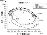
本明細書に提示されるシステム、装置、および方法は、血管内圧の測定値およびポンプパラメータ(「パラメータ」は、心血管系および/または心臓ポンプの信号および/または動作状態を表すことができる)から自己心機能を示す心機能パラメータを決定する。心機能は、本明細書に提示される装置および技術を使用していくつかの異なるやり方で定量化することができ、これには、左室拡張末期圧(left ventricular end diastolic pressure(LVEDP))、収縮性、一回拍出量、駆出率、心腔圧、一回仕事量、心拍出量、心臓パワー出力(cardiac power output)、前負荷状態、後負荷状態、心拍数、心臓の回復、流量負荷状態、変動容積負荷状態、および/または心周期流動状態のうちの1つまたは複数が含まれる。いくつかの用途では、そのような心臓パラメータは、圧力測定値と電流測定値の所与の対に対応する心周期の位相の検出を可能にする、圧力測定値(例えば、大動脈圧と左心室圧との間の差圧、または大動脈圧、または脈管構造内で測定されたもしくは脈管構造内に挿入された装置内で測定された他の圧力)とモータ電流測定値との間のヒステリシスに部分的に基づいて決定される。これらの測定値から、ユーザは、心機能に関する重要な情報を、場合によっては、吸引事象の発生を含む心臓補助装置性能に関する情報を判断することができる。The systems, devices, and methods presented herein determine cardiac function parameters indicative of native cardiac function from measurements of intravascular pressure and pump parameters (where "parameters" can represent signals and/or operating conditions of the cardiovascular system and/or the cardiac pump). Cardiac function can be quantified in several different ways using the devices and techniques presented herein, including one or more of left ventricular end diastolic pressure (LVEDP), contractility, stroke volume, ejection fraction, cardiac chamber pressures, stroke work, cardiac output, cardiac power output, preload state, afterload state, heart rate, cardiac recovery, flow loading state, variable volume loading state, and/or cardiac cycle flow state. In some applications, such cardiac parameters are determined based in part on hysteresis between pressure measurements (e.g., differential pressure between aortic pressure and left ventricular pressure, or aortic pressure, or other pressure measured in the vasculature or in a device inserted in the vasculature) and motor current measurements, which allows detection of the phase of the cardiac cycle corresponding to a given pair of pressure and current measurements. From these measurements, a user can determine important information regarding cardiac function and, in some cases, cardiac assist device performance, including the occurrence of aspiration events.
一局面では、心臓ポンプシステムは、カテーテルと、モータと、モータに動作可能に連結されたロータと、モータを作動させるとロータが駆動されて血液がポンプハウジングを通って送り出されるように、ロータを少なくとも部分的に取り囲むポンプハウジングとを含む。心臓ポンプシステムはまた、経時的に血行動態パラメータを検出するセンサと、コントローラとを含む。コントローラは、経時的にモータパラメータを検出し、経時的にセンサからの検出された血行動態パラメータの入力を受け取り、経時的に測定された血行動態パラメータと経時的に測定されたモータパラメータとの間の関係などの、検出された血行動態パラメータとモータパラメータとの間の関係を決定する。例えば、コントローラは、検出されたモータパラメータおよび血行動態パラメータをメモリに格納し、それらが時間的に整合するように、モータパラメータと血行動態パラメータのデータを関連付けることができる。コントローラは、多項式最良当てはめアルゴリズムを使用して、検出された血行動態パラメータとモータパラメータとの間の関係を特徴付け、特徴付けられた関係をメモリに格納する。例えば、コントローラは、データの全部または一部(例えば、圧力測定値などの血行動態パラメータデータの一部、およびモータ電流測定値などのモータパラメータデータの一部)を、楕円当てはめ、多項式、オイラー方程式などの適切な方程式に当てはめることによって、関係を特徴付けることができる。In one aspect, the heart pump system includes a catheter, a motor, a rotor operably coupled to the motor, and a pump housing at least partially surrounding the rotor such that actuation of the motor drives the rotor to pump blood through the pump housing. The heart pump system also includes a sensor that detects hemodynamic parameters over time, and a controller. The controller detects the motor parameters over time, receives inputs of the detected hemodynamic parameters from the sensor over time, and determines a relationship between the detected hemodynamic parameters and the motor parameters, such as a relationship between the hemodynamic parameters measured over time and the motor parameters measured over time. For example, the controller can store the detected motor parameters and hemodynamic parameters in a memory and associate the data of the motor parameters and the hemodynamic parameters such that they are aligned in time. The controller uses a polynomial best fit algorithm to characterize the relationship between the detected hemodynamic parameters and the motor parameters, and store the characterized relationship in a memory. For example, the controller can characterize the relationship by fitting all or a portion of the data (e.g., a portion of the hemodynamic parameter data, such as pressure measurements, and a portion of the motor parameter data, such as motor current measurements) to a suitable equation, such as an ellipse fit, a polynomial, an Euler equation, etc.
いくつかの実施態様では、モータパラメータは、モータに供給される電流、モータに供給される電力、またはモータ速度である。いくつかの実施態様では、コントローラは、検出された血行動態パラメータとモータパラメータとの間の特徴付けられた関係から変曲点、局所勾配変化、または曲率変化を抽出することによって、少なくとも1つの心血管メトリックを決定する。いくつかの実施態様では、少なくとも1つの心血管メトリックは、収縮性、一回拍出量、駆出率、心腔圧、一回仕事量、心拍出量、心臓パワー出力、左心室圧、前負荷状態、後負荷状態、心拍数、心臓の回復、流量負荷状態、変動容積負荷状態、心周期容積負荷状態、または心周期流動状態のうちの少なくとも1つである。いくつかの実施態様では、少なくとも1つの心血管メトリックは、左室拡張末期圧(LVEDP)である。In some embodiments, the motor parameter is a current supplied to the motor, a power supplied to the motor, or a motor speed. In some embodiments, the controller determines at least one cardiovascular metric by extracting an inflection point, a local slope change, or a curvature change from the characterized relationship between the detected hemodynamic parameter and the motor parameter. In some embodiments, the at least one cardiovascular metric is at least one of contractility, stroke volume, ejection fraction, cardiac chamber pressure, stroke work, cardiac output, cardiac power output, left ventricular pressure, preload state, afterload state, heart rate, cardiac recovery, flow loading state, variable volume loading state, cardiac cycle volume loading state, or cardiac cycle flow state. In some embodiments, the at least one cardiovascular metric is left ventricular end-diastolic pressure (LVEDP).
いくつかの実施態様では、血行動態パラメータは大動脈圧であり、モータパラメータは電流であり、関係を特徴付けることは、測定された電流と測定された電流および大動脈圧から算出された圧力ヘッドとを表すデータの少なくとも一部分に方程式を当てはめることを含む。いくつかの実施態様では、コントローラは、電流および圧力ヘッドデータの少なくとも一部分に当てはめた方程式からLVEDP点を決定し、ルックアップテーブルにアクセスして圧力ヘッドデータにおけるLVEDP点から実際のLVEDP値を決定する。いくつかの実施態様では、LVEDP点を決定することは、電流および圧力ヘッドデータの少なくとも一部分に当てはめられた方程式において変曲点、局所勾配変化、または曲率変化を特定することを含む。In some embodiments, the hemodynamic parameter is an aortic pressure and the motor parameter is an electrical current, and characterizing the relationship includes fitting an equation to at least a portion of the data representing the measured electrical current and a pressure head calculated from the measured electrical current and the aortic pressure. In some embodiments, the controller determines an LVEDP point from the equation fitted to at least a portion of the current and pressure head data and accesses a lookup table to determine an actual LVEDP value from the LVEDP point in the pressure head data. In some embodiments, determining the LVEDP point includes identifying an inflection point, a local slope change, or a curvature change in the equation fitted to at least a portion of the current and pressure head data.
いくつかの実施態様では、コントローラは、検出された血行動態パラメータとモータパラメータとの間の関係から心周期位相を決定する。いくつかの実施態様では、コントローラは、検出された血行動態パラメータとモータパラメータとの間の関係に基づいてヒステリシス曲線を記述し、心周期位相に対応するヒステリシス曲線上のサンプル時間を選択する。In some embodiments, the controller determines the cardiac cycle phase from a relationship between the detected hemodynamic parameter and the motor parameter. In some embodiments, the controller describes a hysteresis curve based on the relationship between the detected hemodynamic parameter and the motor parameter and selects a sample time on the hysteresis curve that corresponds to the cardiac cycle phase.
いくつかの実施態様では、心周期位相を決定することは、サンプル時間が圧力ヘッド増加に対応するヒステリシス曲線のセグメントに対応するときに、心周期位相が拡張期弛緩にあることを検出すること、サンプル時間が、拡張期弛緩の後に続く、勾配もしくは曲率の急激な変化または変曲点の特定によって識別される点までの圧力ヘッド減少に対応するヒステリシス曲線のセグメントに対応するときに、心周期位相が拡張期充満にあることを検出すること、またはサンプル時間が変曲点から最小圧力ヘッドまでの圧力ヘッド減少を有するヒステリシス曲線のセグメントに対応するときに、心周期位相が収縮期にあることを検出することを含む。In some embodiments, determining the cardiac cycle phase includes detecting that the cardiac cycle phase is in diastolic relaxation when the sample time corresponds to a segment of the hysteresis curve corresponding to a pressure head increase, detecting that the cardiac cycle phase is in diastolic filling when the sample time corresponds to a segment of the hysteresis curve corresponding to a pressure head decrease following diastolic relaxation to a point identified by an abrupt change in slope or curvature or identification of an inflection point, or detecting that the cardiac cycle phase is in systole when the sample time corresponds to a segment of the hysteresis curve having a pressure head decrease from an inflection point to a minimum pressure head.
いくつかの実施態様では、モータパラメータおよび血行動態パラメータは、心周期の一部分にわたって検出される。他の実施態様では、モータパラメータおよび血行動態パラメータは、1つまたは複数の心周期にわたって検出される。いくつかの実施態様では、モータは、ロータの作動中にロータの実質的に一定の速度を維持する。いくつかの実施態様では、コントローラは、少なくとも1つの心血管メトリックを、以前に決定された少なくとも1つの心血管メトリックと共にメモリに格納する。いくつかの実施態様では、心臓ポンプシステムはまた、心臓ポンプに近接したカテーテルの遠位端付近に位置決めされた一体型モータも含む。In some embodiments, the motor parameters and hemodynamic parameters are sensed over a portion of a cardiac cycle. In other embodiments, the motor parameters and hemodynamic parameters are sensed over one or more cardiac cycles. In some embodiments, the motor maintains a substantially constant speed of the rotor during operation of the rotor. In some embodiments, the controller stores the at least one cardiovascular metric in memory along with the at least one previously determined cardiovascular metric. In some embodiments, the heart pump system also includes an integral motor positioned near a distal end of the catheter proximate to the heart pump.
別の局面では、心臓ポンプシステムは、カテーテルと、モータと、モータに動作可能に連結されたロータと、モータを作動させるとロータが駆動されて血液がポンプハウジングを通って送り出されるように、ロータを少なくとも部分的に取り囲むポンプハウジングとを含む。心臓ポンプシステムはまた、経時的に大動脈圧を検出する圧力センサと、コントローラとを含む。コントローラは、経時的にモータパラメータを検出し、センサから経時的に大動脈圧を受け取り、モータパラメータと大動脈圧との間の関係をメモリに格納し、LVEDPを示す変曲点が見出され得る期間を決定し、決定された期間に基づいて大動脈圧における変曲点を特定する。In another aspect, the heart pump system includes a catheter, a motor, a rotor operably coupled to the motor, and a pump housing at least partially surrounding the rotor such that actuation of the motor drives the rotor to pump blood through the pump housing. The heart pump system also includes a pressure sensor that detects an aortic pressure over time, and a controller. The controller detects a motor parameter over time, receives the aortic pressure over time from the sensor, stores in memory a relationship between the motor parameter and the aortic pressure, determines a time period during which an inflection point indicative of the LVEDP may be found, and identifies an inflection point in the aortic pressure based on the determined time period.
いくつかの実施態様では、LVEDPを示す変曲点が見出され得る期間を決定することは、受け取ったモータパラメータが変化する期間を特定することを含む。いくつかの実施態様では、コントローラはまた、大動脈圧における変曲点に基づいて、メモリに格納された動的曲線ルックアップテーブルからLVEDPを決定する。いくつかの実施態様では、コントローラはECG信号を受け取り、LVEDPを示す変曲点が見出され得る期間を決定することは、ECG信号が拡張期の最終周期を示す期間を特定することを含む。In some embodiments, determining the time period during which an inflection point indicative of the LVEDP may be found includes identifying a time period during which the received motor parameter changes. In some embodiments, the controller also determines the LVEDP from a dynamic curve lookup table stored in the memory based on an inflection point in the aortic pressure. In some embodiments, the controller receives an ECG signal, and determining the time period during which an inflection point indicative of the LVEDP may be found includes identifying a time period during which the ECG signal indicates a final cycle of diastole.
いくつかの実施態様では、モータパラメータは、モータ電流、モータ電流の変化、モータ電流の変動性、およびモータ電流と圧力の正味の積分面積のうちの1つである。いくつかの実施態様では、コントローラはまた、モータパラメータと大動脈圧との間の関係から心周期位相も決定し、心周期位相は、ECGデータ、血行動態パラメータ、モータパラメータおよびモータ速度、ならびに/または大動脈圧の勾配のうちの1つまたは複数を使用して決定される。いくつかの実施態様では、モータは、ロータの作動中にロータの実質的に一定の速度を維持するように構成される。いくつかの実施態様では、心臓ポンプは、患者の脈管構造内に挿入するためにサイズ決めされかつ構成された一体型モータをさらに含む。In some embodiments, the motor parameter is one of motor current, change in motor current, variability in motor current, and net integral area of motor current and pressure. In some embodiments, the controller also determines a cardiac cycle phase from a relationship between the motor parameter and aortic pressure, the cardiac cycle phase being determined using one or more of the ECG data, the hemodynamic parameter, the motor parameter and the motor speed, and/or aortic pressure gradient. In some embodiments, the motor is configured to maintain a substantially constant speed of the rotor during actuation of the rotor. In some embodiments, the heart pump further includes an integrated motor sized and configured for insertion into the patient's vasculature.
別の局面では、心臓ポンプシステムは、心臓ポンプと電子コントローラとを含む。心臓ポンプは、モータと、モータに動作可能に連結されたロータと、血行動態パラメータのセンサとを含む。コントローラは、モータパラメータ、例えば、モータに供給される電流、モータに供給される電力、またはモータ速度を測定し、センサを使用して経時的に血行動態パラメータを測定するように構成される。コントローラは、最良当てはめアルゴリズムまたは他の適切な処理アルゴリズムに従って決定される、経時的なモータパラメータを表す入力と血行動態パラメータを表す入力とに基づくヒステリシス曲線を決定および記述し、左心室圧を決定するために、測定された患者心臓パラメータ、例えば大動脈圧に基づいて、当てはめられたヒステリシス曲線をスケーリングするように構成される。In another aspect, a heart pump system includes a heart pump and an electronic controller. The heart pump includes a motor, a rotor operably coupled to the motor, and a sensor of a hemodynamic parameter. The controller is configured to measure the motor parameter, e.g., current supplied to the motor, power supplied to the motor, or motor speed, and measure the hemodynamic parameter over time using the sensor. The controller is configured to determine and describe a hysteresis curve based on inputs representing the motor parameter and the hemodynamic parameter over time, as determined according to a best fit algorithm or other suitable processing algorithm, and scale the fitted hysteresis curve based on a measured patient cardiac parameter, e.g., aortic pressure, to determine left ventricular pressure.
いくつかの実施態様では、コントローラは、スケーリングされたヒステリシス曲線から変曲点値を抽出することによって少なくとも1つの心血管メトリックを決定するように構成される。いくつかの適応形態において、少なくとも1つの心血管メトリックは、左室拡張末期圧である。いくつかの実施態様では、ヒステリシス曲線を決定または特徴付けることは、ヒステリシス曲線を当てはめるための多項式を選択することと、曲線を計算するためにコントローラを使用してモータパラメータおよび(例えば、センサ測定値からの)血行動態パラメータを表すデータを処理することとを含む。例えば、モータパラメータおよび測定された血行動態パラメータを示すデータは、メモリまたはサーバのデータベース内のテーブルのデータの配列としてコントローラに格納されてもよく、コントローラは、そのようなデータを取得してヒステリシス曲線を計算するために、そのようなデータテーブルにアクセスし得る。格納されたデータは、後でコントローラによってまたはユーザによってアクセスされることができる。In some implementations, the controller is configured to determine at least one cardiovascular metric by extracting an inflection point value from the scaled hysteresis curve. In some applications, the at least one cardiovascular metric is left ventricular end-diastolic pressure. In some implementations, determining or characterizing the hysteresis curve includes selecting a polynomial for fitting the hysteresis curve and processing data representing the motor parameters and hemodynamic parameters (e.g., from sensor measurements) using the controller to calculate the curve. For example, data indicative of the motor parameters and the measured hemodynamic parameters may be stored in the controller as an array of data in a table in a memory or a database on a server, and the controller may access such data tables to obtain such data and calculate the hysteresis curve. The stored data can be accessed at a later time by the controller or by a user.
いくつかの実施態様では、血行動態パラメータは圧力ヘッドである。いくつかの実施態様では、少なくとも1つの心血管メトリックは、収縮性、一回拍出量、駆出率、心腔圧、一回仕事量、心拍出量、心臓パワー出力、左室拡張末期圧、前負荷状態、後負荷状態、心拍数、心臓の回復、流量負荷状態、変動容積負荷状態、心周期容積負荷状態、および/または心周期流動状態のうちの少なくとも1つである。いくつかの実施態様では、モータは、モータパラメータの測定中にロータの一定の速度を維持する。In some embodiments, the hemodynamic parameter is pressure head. In some embodiments, the at least one cardiovascular metric is at least one of contractility, stroke volume, ejection fraction, cardiac chamber pressure, stroke work, cardiac output, cardiac power output, left ventricular end-diastolic pressure, preload state, afterload state, heart rate, cardiac recovery, flow loading state, variable volume loading state, cardiac cycle volume loading state, and/or cardiac cycle flow state. In some embodiments, the motor maintains a constant rotor speed during measurement of the motor parameter.
いくつかの実施態様では、コントローラは、ヒステリシス曲線から心位相を決定するようにさらに構成される。いくつかの実施態様では、心位相は、ECGデータ、圧力センサで測定された圧力、モータパラメータおよびモータ速度、大動脈圧勾配、ならびに呼吸変動のうちの1つまたは複数を使用して決定される。いくつかの実施態様では、心位相を決定することは、サンプル時間におけるモータパラメータと圧力ヘッドの測定に基づいて、弛緩、収縮、駆出、および充満のうちの1つに対応する、サンプル時間が対応するヒステリシス曲線のセグメントを選択することを含む。いくつかの実施態様では、心位相を決定することは、サンプル時間が高圧を有するヒステリシス曲線のセグメントに対応するときに心位相が拡張期であることを検出することと、サンプル時間が低圧を有するヒステリシス曲線のセグメントに対応するときに心位相が収縮期であることを検出することとをさらに含む。In some embodiments, the controller is further configured to determine the cardiac phase from the hysteresis curve. In some embodiments, the cardiac phase is determined using one or more of the ECG data, the pressure measured by the pressure sensor, the motor parameters and motor speed, the aortic pressure gradient, and respiratory variation. In some embodiments, determining the cardiac phase includes selecting a segment of the hysteresis curve to which the sample time corresponds that corresponds to one of relaxation, contraction, ejection, and filling based on the measurement of the motor parameters and the pressure head at the sample time. In some embodiments, determining the cardiac phase further includes detecting that the cardiac phase is diastole when the sample time corresponds to a segment of the hysteresis curve having a high pressure, and detecting that the cardiac phase is systole when the sample time corresponds to a segment of the hysteresis curve having a low pressure.
別の局面では、心臓ポンプシステムは、モータと、モータに動作可能に連結されたロータと、圧力センサと、コントローラとを含む。コントローラは、モータパラメータを測定し、圧力センサを使用して経時的に圧力ヘッドを測定し、最良当てはめアルゴリズムに従って経時的なモータパラメータと圧力ヘッドとの間のヒステリシスに基づくヒステリシス曲線を記述し、左心室圧を決定するために、測定された大動脈圧に基づいて、当てはめられたヒステリシス曲線をスケーリングし、スケーリングされたヒステリシス曲線から変曲点を抽出することによって少なくとも1つの心血管メトリックを決定し、少なくとも1つの心血管メトリックをコントローラの表示画面に表示するように構成される。In another aspect, a cardiac pump system includes a motor, a rotor operably coupled to the motor, a pressure sensor, and a controller. The controller is configured to measure a motor parameter, measure a pressure head over time using the pressure sensor, describe a hysteresis curve based on the hysteresis between the motor parameter and the pressure head over time according to a best fit algorithm, scale the fitted hysteresis curve based on the measured aortic pressure to determine a left ventricular pressure, determine at least one cardiovascular metric by extracting an inflection point from the scaled hysteresis curve, and display the at least one cardiovascular metric on a display screen of the controller.
いくつかの実施態様では、少なくとも1つの心血管メトリックは、左室拡張末期圧である。いくつかの実施態様では、ヒステリシス曲線を記述することは、ヒステリシス曲線を当てはめるための多項式を選択することを含む。いくつかの実施態様では、少なくとも1つの心血管メトリックは、収縮性、一回拍出量、駆出率、心腔圧、一回仕事量、心拍出量、心臓パワー出力、左室拡張末期圧、前負荷状態、後負荷状態、心拍数、心臓の回復、流量負荷状態、変動容積負荷状態、心周期容積負荷状態、および/または心周期流動状態のうちの少なくとも1つである。いくつかの実施態様では、モータパラメータは、モータ電流、モータ電流の変化、モータ電流の変動性、またはモータ電流と圧力の正味の積分面積である。いくつかの実施態様では、モータは、モータパラメータの測定中に一定のロータ速度を維持する。In some embodiments, the at least one cardiovascular metric is left ventricular end-diastolic pressure. In some embodiments, describing the hysteresis curve includes selecting a polynomial to fit the hysteresis curve. In some embodiments, the at least one cardiovascular metric is at least one of contractility, stroke volume, ejection fraction, cardiac chamber pressure, stroke work, cardiac output, cardiac power output, left ventricular end-diastolic pressure, preload state, afterload state, heart rate, cardiac recovery, flow loading state, variable volume loading state, cardiac cycle volume loading state, and/or cardiac cycle flow state. In some embodiments, the motor parameter is motor current, change in motor current, variability of motor current, or net integrated area of motor current and pressure. In some embodiments, the motor maintains a constant rotor speed during measurement of the motor parameter.
いくつかの実施態様では、コントローラは、ヒステリシス曲線から心位相を決定するようにさらに構成される。いくつかの実施態様では、心位相は、ECGデータ、圧力センサで測定された圧力、モータパラメータおよびモータ速度、大動脈圧勾配、ならびに呼吸変動のうちの1つまたは複数を使用して決定される。いくつかの実施態様では、心位相を決定することは、ヒステリシス曲線にアクセスすること、モータパラメータおよび圧力ヘッドの測定とサンプル時間とに基づいて、サンプル時間が対応する曲線のセグメントを選択すること、ならびにセグメントに基づいて、弛緩、収縮、駆出、または充満のうちの対応する心位相を決定することを含む。In some embodiments, the controller is further configured to determine the cardiac phase from the hysteresis curve. In some embodiments, the cardiac phase is determined using one or more of the ECG data, the pressure measured by the pressure sensor, the motor parameters and motor speed, the aortic pressure gradient, and respiratory variation. In some embodiments, determining the cardiac phase includes accessing the hysteresis curve, selecting a segment of the curve to which the sample time corresponds based on the measurement of the motor parameters and pressure head and the sample time, and determining a corresponding cardiac phase of relaxation, contraction, ejection, or filling based on the segment.
いくつかの実施態様では、モータは、約21フレンチ未満の直径を有する。いくつかの実施態様では、少なくとも1つの心臓メトリックは、収縮性、一回拍出量、駆出率、心腔圧、一回仕事量、心拍出量、心臓パワー出力、左室拡張末期圧、前負荷状態、後負荷状態、心拍数、心臓の回復、流量負荷状態、変動容積負荷状態、心周期容積負荷状態、および/または心周期流動状態のうちの少なくとも1つである。いくつかの実施態様では、コントローラは、少なくとも1つの心臓メトリックが患者の心臓状態の変化を示すときに心臓ポンプによって提供される支援のレベルを自動的に調整するように構成され、患者の心臓状態は、収縮性の変化、容積負荷の変化、前負荷の変化、後負荷の変化、心拍数の変化、および脈圧の変化のうちの少なくとも1つによって定義される。いくつかの実施態様では、コントローラは、自己心機能を増強および改善するために心臓ポンプによって提供される支援のレベルまたは方法を自動化するように構成され、支援のレベルまたは方法を自動化することは、心臓ポンプによって送り出される血流量を変更すること、自動血流脈動の周波数および/または振幅を変更すること、ならびにロータの回転速度を変更することのうちの少なくとも1つを含む。いくつかの実施態様では、モータは、モータパラメータの測定中に一定のモータ速度を維持する。In some embodiments, the motor has a diameter of less than about 21 French. In some embodiments, the at least one cardiac metric is at least one of contractility, stroke volume, ejection fraction, cardiac chamber pressure, stroke work, cardiac output, cardiac power output, left ventricular end-diastolic pressure, preload state, afterload state, heart rate, cardiac recovery, flow loading state, variable volume loading state, cardiac cycle volume loading state, and/or cardiac cycle flow state. In some embodiments, the controller is configured to automatically adjust a level of assistance provided by the cardiac pump when the at least one cardiac metric indicates a change in the patient's cardiac condition, the patient's cardiac condition being defined by at least one of a change in contractility, a change in volume loading, a change in preload, a change in afterload, a change in heart rate, and a change in pulse pressure. In some embodiments, the controller is configured to automate a level or method of support provided by the heart pump to enhance and improve native heart function, where automating the level or method of support includes at least one of altering the blood flow rate pumped by the heart pump, altering the frequency and/or amplitude of the automated blood flow pulsations, and altering the rotational speed of the rotor. In some embodiments, the motor maintains a constant motor speed during the measurement of the motor parameter.
いくつかの実施態様では、心位相を決定することは、ヒステリシスループを形成する、モータパラメータの関数としての圧力のプロットにアクセスすることと、サンプル時間におけるモータパラメータおよび圧力の測定を使用して、各セグメントが心位相に対応する、サンプル時間が対応するヒステリシスループのセグメントを特定することとを含む。いくつかの実施態様では、心位相はECGデータを使用して決定される。いくつかの実施態様では、心位相は、圧力センサで測定された圧力を使用して決定される。いくつかの実施態様では、心位相を決定することは、サンプル時間が高圧を有するヒステリシスループのセグメントに対応する場合に心位相が拡張期であることを検出することと、サンプル時間が低圧を有するヒステリシスループのセグメントに対応する場合に心位相が収縮期であることを検出することとをさらに含む。In some embodiments, determining the cardiac phase includes accessing a plot of pressure as a function of the motor parameter forming a hysteresis loop and using measurements of the motor parameter and pressure at sample times to identify segments of the hysteresis loop to which the sample times correspond, each segment corresponding to a cardiac phase. In some embodiments, the cardiac phase is determined using the ECG data. In some embodiments, the cardiac phase is determined using pressure measured by the pressure sensor. In some embodiments, determining the cardiac phase further includes detecting that the cardiac phase is diastole when the sample time corresponds to a segment of the hysteresis loop having a high pressure, and detecting that the cardiac phase is systole when the sample time corresponds to a segment of the hysteresis loop having a low pressure.
いくつかの実施態様では、コントローラは、モータパラメータがプロットの第1の座標であり、圧力がプロットの第2の座標である、圧力およびモータパラメータの測定値のプロットを生成するように、またはモータパラメータと圧力システムとの関係を監視するように構成される。いくつかの実施態様では、血液ポンプは経皮的である。いくつかの実施態様では、モータは植え込み型である。いくつかの実施態様では、心臓ポンプシステムは、ロータが大動脈内に配置されたときに圧力センサが大動脈内に位置決めされるように構成される。いくつかの実施態様では、心臓ポンプシステムは血管内心臓ポンプシステムである。In some embodiments, the controller is configured to generate a plot of pressure and motor parameter measurements, where the motor parameter is a first coordinate of the plot and the pressure is a second coordinate of the plot, or to monitor a relationship between the motor parameter and the pressure system. In some embodiments, the blood pump is percutaneous. In some embodiments, the motor is implantable. In some embodiments, the heart pump system is configured such that the pressure sensor is positioned in the aorta when the rotor is disposed in the aorta. In some embodiments, the heart pump system is an intravascular heart pump system.
別の局面では、心臓ポンプシステムは、心臓ポンプとコントローラとを含む。心臓ポンプは、モータと、モータに動作可能に連結されたロータと、血行動態パラメータのセンサ、例えば圧力センサとを含む。コントローラは、モータパラメータを測定し、センサによって血行動態パラメータを測定し、心位相を決定し、心機能を示す少なくとも1つの心臓メトリックを決定し、少なくとも1つの心臓メトリックをコントローラの表示画面に表示するように構成される。例えば、コントローラは、モータに供給される電流またはモータに供給される電力のモータパラメータを測定し、圧力センサにおいて圧力を測定し、心機能を示す少なくとも1つの心臓メトリックを決定し、少なくとも1つの心臓メトリックをコントローラの表示画面に表示するように構成され得る。心機能を示す心臓メトリックは、所定の圧力・モータ曲線を使用して決定されてよく、少なくとも1つの心臓メトリックの決定は、モータパラメータと圧力との間のヒステリシスに基づくものであってよい。In another aspect, a heart pump system includes a heart pump and a controller. The heart pump includes a motor, a rotor operably coupled to the motor, and a sensor of a hemodynamic parameter, e.g., a pressure sensor. The controller is configured to measure the motor parameter, measure the hemodynamic parameter by the sensor, determine a cardiac phase, determine at least one cardiac metric indicative of cardiac function, and display the at least one cardiac metric on a display screen of the controller. For example, the controller may be configured to measure a motor parameter of a current supplied to the motor or a power supplied to the motor, measure a pressure at a pressure sensor, determine at least one cardiac metric indicative of cardiac function, and display the at least one cardiac metric on a display screen of the controller. The cardiac metric indicative of cardiac function may be determined using a predetermined pressure-motor curve, and the determination of the at least one cardiac metric may be based on a hysteresis between the motor parameter and the pressure.
いくつかの実施態様において、測定される圧力は、大動脈圧、または大動脈圧と左心室圧との間の圧力差のうちの1つである。いくつかの実施態様では、少なくとも1つの心臓メトリックは、収縮性、一回拍出量、駆出率、心腔圧、一回仕事量、心拍出量、心臓パワー出力、左室拡張末期圧、前負荷状態、後負荷状態、心拍数、心臓の回復、流量負荷状態、変動容積負荷状態、心周期容積負荷状態、および/または心周期流動状態のうちの少なくとも1つである。いくつかの実施態様では、コントローラは、少なくとも1つの心臓メトリックが患者の心臓状態の変化を示すときに心臓ポンプによって提供される支援のレベルを自動的に調整するように構成され、患者の心臓状態は、収縮性の変化、容積負荷の変化、前負荷の変化、後負荷の変化、心拍数の変化、および脈圧の変化のうちの少なくとも1つによって定義される。いくつかの実施態様では、コントローラは、自己心機能を増強および改善するために心臓ポンプによって提供される支援のレベルまたは方法を自動化するように構成され、支援のレベルまたは方法を自動化することは、心臓ポンプによって送り出される血流量を変更すること、自動血流脈動の周波数および/または振幅を変更すること、ならびにロータの回転速度を変更することのうちの少なくとも1つを含む。いくつかの実施態様では、モータは、モータパラメータの測定中に一定のモータ速度を維持する。In some embodiments, the pressure measured is one of aortic pressure or a pressure difference between aortic pressure and left ventricular pressure. In some embodiments, the at least one cardiac metric is at least one of contractility, stroke volume, ejection fraction, cardiac chamber pressure, stroke work, cardiac output, cardiac power output, left ventricular end-diastolic pressure, preload state, afterload state, heart rate, cardiac recovery, flow loading state, variable volume loading state, cardiac cycle volume loading state, and/or cardiac cycle flow state. In some embodiments, the controller is configured to automatically adjust the level of assistance provided by the cardiac pump when the at least one cardiac metric indicates a change in the patient's cardiac condition, the patient's cardiac condition being defined by at least one of a change in contractility, a change in volume loading, a change in preload, a change in afterload, a change in heart rate, and a change in pulse pressure. In some embodiments, the controller is configured to automate a level or method of support provided by the heart pump to enhance and improve native heart function, where automating the level or method of support includes at least one of altering the blood flow rate pumped by the heart pump, altering the frequency and/or amplitude of the automated blood flow pulsations, and altering the rotational speed of the rotor. In some embodiments, the motor maintains a constant motor speed during the measurement of the motor parameter.
いくつかの実施態様では、心位相を決定することは、ヒステリシスループを形成する、モータパラメータの関数としての圧力のプロットにアクセスすることと、サンプル時間におけるモータパラメータおよび圧力の測定を使用して、各セグメントが心位相に対応する、サンプル時間が対応するヒステリシスループのセグメントを決定することとを含む。いくつかの実施態様では、心位相はECGデータを使用して決定される。いくつかの実施態様では、心位相は、圧力センサで測定された圧力を使用して決定される。いくつかの実施態様では、心位相を決定することは、サンプル時間が高圧を有するヒステリシスループのセグメントに対応する場合に心位相が拡張期であることを検出することと、サンプル時間が低圧を有するヒステリシスループのセグメントに対応する場合に心位相が収縮期であることを検出することとをさらに含む。In some embodiments, determining the cardiac phase includes accessing a plot of pressure as a function of a motor parameter forming a hysteresis loop and using measurements of the motor parameter and pressure at sample times to determine segments of the hysteresis loop to which the sample times correspond, each segment corresponding to a cardiac phase. In some embodiments, the cardiac phase is determined using ECG data. In some embodiments, the cardiac phase is determined using pressure measured by a pressure sensor. In some embodiments, determining the cardiac phase further includes detecting that the cardiac phase is diastole when the sample time corresponds to a segment of the hysteresis loop having a high pressure, and detecting that the cardiac phase is systole when the sample time corresponds to a segment of the hysteresis loop having a low pressure.
いくつかの実施態様では、コントローラは、モータパラメータがプロットの第1の座標であり、圧力がプロットの第2の座標である、圧力およびモータパラメータの測定値のプロットを生成するように、またはモータパラメータと圧力システムとの関係を監視するように構成される。いくつかの実施態様では、血液ポンプは経皮的である。いくつかの実施態様では、モータは植え込み型である。いくつかの実施態様では、心臓ポンプシステムは、ロータが大動脈内に配置されたときに圧力センサが大動脈内に位置決めされるように構成される。いくつかの実施態様では、モータパラメータは、モータ電流、モータ電流の変化、モータ電流の変動性、ならびにモータ電流および圧力の正味の積分面積のうちの1つである。いくつかの実施態様では、心臓ポンプシステムは血管内心臓ポンプシステムである。In some embodiments, the controller is configured to generate a plot of pressure and motor parameter measurements, where the motor parameter is a first coordinate of the plot and the pressure is a second coordinate of the plot, or to monitor a relationship between the motor parameter and the pressure system. In some embodiments, the blood pump is percutaneous. In some embodiments, the motor is implantable. In some embodiments, the heart pump system is configured such that the pressure sensor is positioned in the aorta when the rotor is disposed in the aorta. In some embodiments, the motor parameter is one of motor current, change in motor current, variability in motor current, and net integrated area of motor current and pressure. In some embodiments, the heart pump system is an intravascular heart pump system.
別の局面では、心臓ポンプシステムは、心臓ポンプとコントローラとを含む。心臓ポンプは、モータと、モータに動作可能に連結されたロータと、圧力センサとを含む。コントローラは、モータに供給される電流またはモータに供給される電力であるモータパラメータを測定し、圧力センサにおいて圧力を測定し、心位相を決定し、心機能を示す少なくとも1つの心臓メトリックを決定し、少なくとも1つの心臓メトリックに基づいて心臓ポンプを動作させるための変更の少なくとも1つの推奨事項を決定し、少なくとも1つの推奨事項をコントローラの表示画面に表示するように構成される。心機能を示す心臓メトリックは、所定の圧力・モータ曲線を使用して決定され、少なくとも1つの心臓メトリックの決定は、モータパラメータと圧力との間のヒステリシスに基づく。In another aspect, a heart pump system includes a heart pump and a controller. The heart pump includes a motor, a rotor operably coupled to the motor, and a pressure sensor. The controller is configured to measure a motor parameter, the motor parameter being a current supplied to the motor or a power supplied to the motor, measure a pressure at the pressure sensor, determine a cardiac phase, determine at least one cardiac metric indicative of cardiac function, determine at least one recommendation of a change to operate the heart pump based on the at least one cardiac metric, and display the at least one recommendation on a display screen of the controller. The cardiac metric indicative of cardiac function is determined using a predetermined pressure-motor curve, and the determination of the at least one cardiac metric is based on a hysteresis between the motor parameter and the pressure.
いくつかの実施態様では、少なくとも1つの推奨事項は、ロータの回転速度を変更すること、モータに供給される電力を変更すること、および/または患者から心臓ポンプを取り外すことを含む。いくつかの実施態様では、少なくとも1つの心臓メトリックは、収縮性、一回拍出量、駆出率、心腔拡張、心腔肥大、心腔圧、一回仕事量、心拍出量、心臓パワー出力、左室拡張末期圧、前負荷状態、後負荷状態、心拍数、および心臓の回復のうちの少なくとも1つである。いくつかの実施態様では、コントローラは、少なくとも1つの心臓メトリックが患者の心臓状態の変化を示すときに心臓ポンプによって提供される支援のレベルを自動的に調整するように構成され、患者の心臓状態は、収縮性の変化、容積負荷の変化、前負荷の変化、後負荷の変化、心拍数の変化、および脈圧の変化のうちの少なくとも1つによって定義される。いくつかの実施態様では、コントローラは、自己心機能を増強および改善するために心臓ポンプによって提供される支援のレベルまたは方法を自動化するように構成され、支援のレベルまたは方法を自動化することは、心臓ポンプによって送り出される血流量を変更すること、自動血流脈動の周波数および/または振幅を変更すること、ならびにロータの回転速度を変更することのうちの少なくとも1つを含む。いくつかの実施態様では、モータは、モータパラメータの測定中に一定のモータ速度を維持する。In some embodiments, the at least one recommendation includes modifying the rotational speed of the rotor, modifying the power supplied to the motor, and/or removing the heart pump from the patient. In some embodiments, the at least one cardiac metric is at least one of contractility, stroke volume, ejection fraction, heart chamber dilation, heart chamber hypertrophy, heart chamber pressure, stroke work, cardiac output, cardiac power output, left ventricular end diastolic pressure, preload state, afterload state, heart rate, and cardiac recovery. In some embodiments, the controller is configured to automatically adjust a level of assistance provided by the heart pump when the at least one cardiac metric indicates a change in the patient's cardiac condition, the patient's cardiac condition being defined by at least one of a change in contractility, a change in volume loading, a change in preload, a change in afterload, a change in heart rate, and a change in pulse pressure. In some embodiments, the controller is configured to automate a level or method of support provided by the heart pump to enhance and improve native heart function, where automating the level or method of support includes at least one of altering the blood flow rate pumped by the heart pump, altering the frequency and/or amplitude of the automated blood flow pulsations, and altering the rotational speed of the rotor. In some embodiments, the motor maintains a constant motor speed during the measurement of the motor parameter.
いくつかの実施態様では、心位相を決定することは、ヒステリシスループを形成する、モータパラメータの関数としての圧力のプロットにアクセスすることと、サンプル時間におけるモータパラメータおよび圧力の測定を使用して、各セグメントが心位相に対応する、サンプル時間が対応するヒステリシスループのセグメントを特定することとを含む。いくつかの実施態様では、心位相はECGデータを使用して決定される。いくつかの実施態様では、心位相は、圧力センサで測定された圧力を使用して決定される。いくつかの実施態様では、心位相を決定することは、サンプル時間が高圧を有するヒステリシスループのセグメントに対応する場合に心位相が拡張期であることを検出することと、サンプル時間が低圧を有するヒステリシスループのセグメントに対応する場合に心位相が収縮期であることを検出することとをさらに含む。In some embodiments, determining the cardiac phase includes accessing a plot of pressure as a function of the motor parameter forming a hysteresis loop and using measurements of the motor parameter and pressure at sample times to identify segments of the hysteresis loop to which the sample times correspond, each segment corresponding to a cardiac phase. In some embodiments, the cardiac phase is determined using the ECG data. In some embodiments, the cardiac phase is determined using pressure measured by the pressure sensor. In some embodiments, determining the cardiac phase further includes detecting that the cardiac phase is diastole when the sample time corresponds to a segment of the hysteresis loop having a high pressure, and detecting that the cardiac phase is systole when the sample time corresponds to a segment of the hysteresis loop having a low pressure.
いくつかの実施態様では、コントローラは、モータパラメータがプロットの第1の座標であり、圧力がプロットの第2の座標である、圧力およびモータパラメータの測定値のプロットを生成するように、またはモータパラメータと圧力システムとの関係を監視するように構成される。いくつかの実施態様では、血液ポンプは経皮的である。いくつかの実施態様では、モータは植え込み型である。いくつかの実施態様では、心臓ポンプシステムは、ロータが大動脈内に配置されたときに圧力センサが大動脈内に位置決めされるように構成される。いくつかの実施態様では、モータパラメータは、モータ電流、モータ電流の変化、モータ電流の変動性、ならびにモータ電流および圧力の正味の積分面積のうちの1つである。いくつかの実施態様では、心臓ポンプシステムは血管内心臓ポンプシステムである。In some embodiments, the controller is configured to generate a plot of pressure and motor parameter measurements, where the motor parameter is a first coordinate of the plot and the pressure is a second coordinate of the plot, or to monitor a relationship between the motor parameter and the pressure system. In some embodiments, the blood pump is percutaneous. In some embodiments, the motor is implantable. In some embodiments, the heart pump system is configured such that the pressure sensor is positioned in the aorta when the rotor is disposed in the aorta. In some embodiments, the motor parameter is one of motor current, change in motor current, variability in motor current, and net integrated area of motor current and pressure. In some embodiments, the heart pump system is an intravascular heart pump system.
別の局面では、心臓ポンプシステムは、心臓ポンプとコントローラとを含む。心臓ポンプは、ロータと、ロータに連結されたモータと、血液入口と、圧力センサとを含む。コントローラは、モータおよび圧力センサと通信する。コントローラは、サンプル時間にモータパラメータを測定し、サンプル時間に圧力センサにおいて圧力を測定し、サンプル時間におけるモータパラメータおよび圧力の測定に基づいて血液入口が閉塞されているかどうか判断するように構成され、血液入口の閉塞は、モータパラメータと圧力センサにおける圧力の測定におけるヒステリシスを使用して判断される。いくつかの実施態様では、コントローラは、血液入口が閉塞されていると判断したことに応答して警告パラメータを表示するように構成される。
[本発明1001]
カテーテルと、
モータと、
前記モータに動作可能に連結されたロータと、
前記モータを作動させると前記ロータが駆動されて血液がポンプハウジングを通って送り出されるように、前記ロータを少なくとも部分的に取り囲む前記ポンプハウジングと、
経時的に血行動態パラメータを検出するように構成されたセンサと、
前記モータと関連付けられたモータパラメータを経時的に検出し、
経時的に前記センサからの前記検出された血行動態パラメータの入力を受け取り、
前記検出された血行動態パラメータと前記検出されたモータパラメータとの間の関係を決定し、
多項式最良当てはめアルゴリズムを使用して、前記血行動態パラメータと前記モータパラメータとの間の前記関係を特徴付け、
前記決定された関係をメモリに格納する
ように構成されたコントローラと
を含む、心臓ポンプシステム。
[本発明1002]
前記モータパラメータが、前記モータに供給される電流、前記モータに供給される電力、またはモータ速度である、本発明1001の心臓ポンプシステム。
[本発明1003]
前記コントローラが、前記検出された血行動態パラメータと前記モータパラメータとの間の前記特徴付けられた関係から変曲点、局所勾配変化、または曲率変化を抽出することによって少なくとも1つの心血管メトリックを決定するようにさらに構成されている、本発明1001または1002の心臓ポンプシステム。
[本発明1004]
前記少なくとも1つの心血管メトリックが、収縮性、一回拍出量、駆出率、心腔圧、一回仕事量、心拍出量、心臓パワー出力(cardiac power output)、左心室圧、前負荷状態、後負荷状態、心拍数、心臓の回復、流量負荷状態、変動容積負荷状態、心周期容積負荷状態、または心周期流動状態のうちの少なくとも1つである、本発明1001~1003のいずれかの心臓ポンプシステム。
[本発明1005]
前記少なくとも1つの心血管メトリックが左室拡張末期圧(LVEDP)である、本発明1004の心臓ポンプシステム。
[本発明1006]
前記血行動態パラメータが大動脈圧であり、前記モータパラメータが電流であり、前記関係を特徴付けることが、前記測定された電流と前記測定された電流および前記大動脈圧から算出された圧力ヘッドとを表すデータの少なくとも一部分に方程式を当てはめることを含む、本発明1001~1005のいずれかの心臓ポンプシステム。
[本発明1007]
前記コントローラが、
前記測定された電流および圧力ヘッドを表す前記データの少なくとも一部分に当てはめられた前記方程式から、LVEDP点を決定し、
ルックアップテーブルにアクセスして、前記圧力ヘッドデータにおける前記LVEDP点から実際のLVEDP値を決定する
ようにさらに構成されている、本発明1001~1006のいずれかの心臓ポンプシステム。
[本発明1008]
LVEDP点を決定することが、前記電流および前記圧力ヘッドの少なくとも一部分に当てはめられた前記方程式において勾配の変化、曲率の変化、または変曲点を特定することを含む、本発明1001~1007のいずれかの心臓ポンプシステム。
[本発明1009]
前記コントローラが、前記検出された血行動態パラメータと前記モータパラメータとの間の前記関係から心周期位相を決定するようにさらに構成されている、本発明1001~1008のいずれかの心臓ポンプシステム。
[本発明1010]
前記コントローラが、
前記検出された血行動態パラメータと前記モータパラメータとの間の前記関係に基づいてヒステリシス曲線を記述し、
前記心周期位相に対応する前記ヒステリシス曲線上のサンプル時間を選択する
ようにさらに構成されている、本発明1001~1009のいずれかの心臓ポンプシステム。
[本発明1011]
前記心周期位相を決定することが、
前記サンプル時間が圧力ヘッド増加に対応する前記ヒステリシス曲線のセグメントに対応するときに、前記心周期位相が拡張期弛緩にあることを検出すること、または
前記サンプル時間が、拡張期弛緩の後に続く、勾配もしくは曲率の急激な変化または変曲点の特定によって識別される点までの圧力ヘッド減少に対応する前記ヒステリシス曲線のセグメントに対応するときに、前記心周期位相が拡張期充満にあることを検出すること、または
前記サンプル時間が前記変曲点から最小圧力ヘッドまでの圧力ヘッド減少を有する前記ヒステリシス曲線のセグメントに対応するときに、前記心周期位相が収縮期にあることを検出すること
をさらに含む、本発明1001~1010のいずれかの心臓ポンプシステム。
[本発明1012]
前記モータパラメータおよび血行動態パラメータが、心周期の一部分にわたって検出される、本発明1001~1011のいずれかの心臓ポンプシステム。
[本発明1013]
前記モータパラメータおよび血行動態パラメータが、1つまたは複数の心周期にわたって検出される、本発明1001~1012のいずれかの心臓ポンプシステム。
[本発明1014]
前記モータが、前記ロータの作動中に前記ロータの実質的に一定の速度を維持するように構成されている、本発明1001~1013のいずれかの心臓ポンプシステム。
[本発明1015]
前記コントローラが、前記少なくとも1つの心血管メトリックを、以前に決定された少なくとも1つの心血管メトリックと共にメモリに格納するようにさらに構成されている、本発明1001~1015のいずれかの心臓ポンプシステム。
[本発明1016]
前記心臓ポンプに近接した前記カテーテルの遠位端付近に位置決めされた一体型モータを含む、本発明1001~1016のいずれかの心臓ポンプシステム。
[本発明1017]
カテーテルと、
モータと、
前記モータに動作可能に連結されたロータと、
前記モータを作動させると前記ロータが駆動されて血液がポンプハウジングを通って送り出されるように、前記ロータを少なくとも部分的に取り囲む前記ポンプハウジングと、
経時的に大動脈圧を検出するように構成された圧力センサと、
経時的にモータパラメータを検出し、
前記センサから経時的に前記大動脈圧を受け取り、
前記モータパラメータと前記大動脈圧との間の関係をメモリに格納し、
LVEDPを示す変曲点が見出され得る期間を決定し、
前記決定された期間に基づいて前記大動脈圧における前記変曲点を特定する
ように構成されたコントローラと
を含む、心臓ポンプシステム。
[本発明1018]
LVEDPを示す前記変曲点が見出され得る期間を決定することが、前記受け取ったモータパラメータが変化する期間を特定することを含む、本発明1017の心臓ポンプシステム。
[本発明1019]
前記コントローラが、前記大動脈圧における前記変曲点に基づいて、前記メモリ内の動的曲線ルックアップテーブルからLVEDPを決定するようにさらに構成されている、本発明1017または1018の心臓ポンプシステム。
[本発明1020]
前記コントローラがECG信号を受け取るようにさらに構成され、LVEDPを示す変曲点が見出され得る期間を決定することが、前記ECG信号が拡張期の最終周期を示す期間を特定することを含む、本発明1017~1019のいずれかの心臓ポンプシステム。
[本発明1021]
前記コントローラが、格納された差圧から、少なくとも1つの心臓メトリックを決定するようにさらに構成され、前記心臓メトリックが、収縮性、一回拍出量、駆出率、心腔圧、一回仕事量、心拍出量、心臓パワー出力、左心室圧、前負荷状態、後負荷状態、心拍数、心臓の回復、流量負荷状態、変動容積負荷状態、心周期容積負荷状態、または心周期流動状態のうちの少なくとも1つである、本発明1017~1020のいずれかの心臓ポンプシステム。
[本発明1022]
前記モータパラメータが、モータ電流、モータ電流の変化、モータ電流の変動性、およびモータ電流と圧力の正味の積分面積のうちの1つである、本発明1017~1021のいずれかの心臓ポンプシステム。
[本発明1023]
前記コントローラが、前記モータパラメータと前記大動脈圧との間の前記関係から心周期位相を決定するようにさらに構成され、前記心周期位相が、ECGデータ、血行動態パラメータ、前記モータパラメータおよびモータ速度、ならびに/または前記大動脈圧の勾配のうちの1つまたは複数を使用して決定される、本発明1017~1022のいずれかの心臓ポンプシステム。
[本発明1024]
前記モータが、前記ロータの作動中に実質的に一定のロータ速度を維持するように構成されている、本発明1017~1023のいずれかの心臓ポンプシステム。
[本発明1025]
前記心臓ポンプが、患者の脈管構造内に挿入するためにサイズ決めされかつ構成された一体型モータをさらに含む、本発明1017~1024のいずれかの心臓ポンプシステム。 In another aspect, a heart pump system includes a heart pump and a controller. The heart pump includes a rotor, a motor coupled to the rotor, a blood inlet, and a pressure sensor. The controller is in communication with the motor and the pressure sensor. The controller is configured to measure a motor parameter at a sample time, measure a pressure at the pressure sensor at the sample time, and determine if the blood inlet is occluded based on the measurements of the motor parameter and the pressure at the sample time, where occlusion of the blood inlet is determined using hysteresis in the measurements of the motor parameter and the pressure at the pressure sensor. In some implementations, the controller is configured to display an alert parameter in response to determining that the blood inlet is occluded.
[The present invention 1001]
A catheter;
A motor;
a rotor operably connected to the motor;
a pump housing at least partially surrounding the rotor such that actuation of the motor drives the rotor to pump blood through the pump housing;
a sensor configured to detect a hemodynamic parameter over time;
Detecting a motor parameter associated with the motor over time;
receiving an input of the detected hemodynamic parameter from the sensor over time;
determining a relationship between the sensed hemodynamic parameter and the sensed motor parameter;
characterizing the relationship between the hemodynamic parameter and the motor parameter using a polynomial best-fit algorithm;
and a controller configured to store the determined relationship in a memory.
[The present invention 1002]
The heart pump system of the present invention 1001, wherein the motor parameter is a current supplied to the motor, a power supplied to the motor, or a motor speed.
[The present invention 1003]
The heart pump system of the
[The present invention 1004]
Any of the heart pump systems of the present inventions 1001 to 1003, wherein the at least one cardiovascular metric is at least one of contractility, stroke volume, ejection fraction, cardiac chamber pressure, stroke work, cardiac output, cardiac power output, left ventricular pressure, preload state, afterload state, heart rate, cardiac recovery, flow load state, variable volume load state, cardiac cycle volume load state, or cardiac cycle flow state.
[The present invention 1005]
The heart pump system of the
[The present invention 1006]
Any of the heart pump systems of the present inventions 1001 to 1005, wherein the hemodynamic parameter is aortic pressure, the motor parameter is current, and characterizing the relationship includes fitting an equation to at least a portion of data representing the measured current and a pressure head calculated from the measured current and the aortic pressure.
[The present invention 1007]
The controller:
determining an LVEDP point from said equation fitted to at least a portion of said data representing said measured current and pressure head;
The heart pump system of any of claims 1001-1006, further configured to access a lookup table to determine an actual LVEDP value from said LVEDP point in said pressure head data.
[The present invention 1008]
Any of the heart pump systems of the present invention 1001-1007, wherein determining the LVEDP point includes identifying a change in slope, change in curvature, or inflection point in the equation fitted to at least a portion of the current and pressure head.
[The present invention 1009]
The heart pump system of any of claims 1001 to 1008, wherein the controller is further configured to determine a cardiac cycle phase from the relationship between the detected hemodynamic parameter and the motor parameter.
[The present invention 1010]
The controller:
describing a hysteresis curve based on the relationship between the detected hemodynamic parameter and the motor parameter;
The heart pump system of any of claims 1001 to 1009, further configured to select a sample time on the hysteresis curve that corresponds to the cardiac cycle phase.
[The present invention 1011]
determining the cardiac cycle phase
Any of the heart pump systems of inventions 1001 to 1010 further comprising: detecting that the cardiac cycle phase is in diastolic relaxation when the sample time corresponds to a segment of the hysteresis curve corresponding to a pressure head increase; or detecting that the cardiac cycle phase is in diastolic filling when the sample time corresponds to a segment of the hysteresis curve corresponding to a pressure head decrease following diastolic relaxation to a point identified by an abrupt change in slope or curvature or identification of an inflection point; or detecting that the cardiac cycle phase is in systole when the sample time corresponds to a segment of the hysteresis curve having a pressure head decrease from the inflection point to a minimum pressure head.
[The present invention 1012]
The heart pump system of any of claims 1001 to 1011, wherein the motor parameters and hemodynamic parameters are sensed over a portion of the cardiac cycle.
[The present invention 1013]
The heart pump system of any of claims 1001-1012, wherein the motor parameters and hemodynamic parameters are sensed over one or more cardiac cycles.
[The present invention 1014]
The heart pump system of any one of claims 1001 to 1013, wherein the motor is configured to maintain a substantially constant speed of the rotor during operation of the rotor.
[The present invention 1015]
The heart pump system of any of claims 1001-1015, wherein the controller is further configured to store the at least one cardiovascular metric in a memory together with at least one previously determined cardiovascular metric.
[The present invention 1016]
The heart pump system of any of claims 1001-1016, comprising an integrated motor positioned near the distal end of the catheter proximate to the heart pump.
[The present invention 1017]
A catheter;
A motor;
a rotor operably connected to the motor;
a pump housing at least partially surrounding the rotor such that actuation of the motor drives the rotor to pump blood through the pump housing;
a pressure sensor configured to detect aortic pressure over time;
Detect motor parameters over time,
receiving the aortic pressure from the sensor over time;
storing a relationship between said motor parameter and said aortic pressure in a memory;
Determine the time period during which an inflection point indicative of LVEDP can be found;
and a controller configured to identify the inflection point in the aortic pressure based on the determined time period.
[The present invention 1018]
The heart pump system of the present invention 1017, wherein determining the period during which the inflection point indicative of LVEDP can be found includes identifying a period during which the received motor parameter changes.
[The present invention 1019]
The heart pump system of the
[The present invention 1020]
Any of the heart pump systems of the present inventions 1017 to 1019, wherein the controller is further configured to receive an ECG signal, and determining a period during which an inflection point indicative of LVEDP can be found includes identifying a period during which the ECG signal indicates the final cycle of diastole.
[The present invention 1021]
Any of the heart pump systems of the present inventions 1017 to 1020, wherein the controller is further configured to determine at least one cardiac metric from the stored differential pressure, the cardiac metric being at least one of contractility, stroke volume, ejection fraction, cardiac chamber pressure, stroke work, cardiac output, cardiac power output, left ventricular pressure, preload state, afterload state, heart rate, cardiac recovery, flow load state, variable volume load state, cardiac cycle volume load state, or cardiac cycle flow state.
[The present invention 1022]
The heart pump system of any of claims 1017 to 1021, wherein the motor parameter is one of motor current, change in motor current, variability of motor current, and net integral area of motor current and pressure.
[The present invention 1023]
Any of the heart pump systems of the present inventions 1017 to 1022, wherein the controller is further configured to determine a cardiac cycle phase from the relationship between the motor parameters and the aortic pressure, the cardiac cycle phase being determined using one or more of ECG data, hemodynamic parameters, the motor parameters and motor speed, and/or a gradient of the aortic pressure.
[The present invention 1024]
The heart pump system of any one of claims 1017 to 1023, wherein the motor is configured to maintain a substantially constant rotor speed during operation of the rotor.
[The present invention 1025]
The heart pump system of any of claims 1017 to 1024, wherein the heart pump further comprises an integral motor sized and configured for insertion within the patient's vasculature.
上記およびその他の目的および利点は、以下の詳細な説明を添付の図面と併せて考察すれば明らかになるであろう。図面において、同様の参照符号は全体を通して同様の部分を指す。These and other objects and advantages will become apparent from the following detailed description considered in conjunction with the accompanying drawings, in which like reference characters refer to like parts throughout.
詳細な説明
本明細書に記載されるシステム、方法、および装置の全体的な理解を提供するために、ある特定の例示的な態様について説明する。本明細書に記載される態様および特徴は、経皮的心臓ポンプシステムに関連して使用するために特に説明されているが、以下で概説されるすべての構成要素および他の特徴は、任意の適切な方法で互いに組み合わされてもよく、外科的切開を使用して植え込まれた心臓補助装置などを含む、他の種類の心臓治療および心臓補助装置にも適合および応用されてもよいことが理解されよう。DETAILED DESCRIPTION In order to provide an overall understanding of the systems, methods, and devices described herein, certain exemplary aspects will be described. Although the aspects and features described herein are specifically described for use in connection with a percutaneous heart pump system, it will be understood that all components and other features outlined below may be combined with one another in any suitable manner and may also be adapted and applied to other types of cardiac therapy and cardiac assist devices, including cardiac assist devices implanted using a surgical incision, and the like.
本明細書に記載されるシステム、装置、および方法は、臓器内に全部または一部が存在する支援装置がその臓器の機能を評価することを可能にする。特に、これらのシステム、装置、および方法は、経皮的補助人工心臓などの心臓補助装置が、心臓の機能を評価するのに使用されることを可能にする。例えば、心臓の状態は、患者の心臓内に位置決めされた補助人工心臓の電気機械コントローラの値を追跡することによって測定または監視することができる。装置は心臓の心腔内圧力の変化に応答してモータ電流を変化させることによって一定のロータ速度を維持するので、モータパラメータおよび圧力、例えば、モータ電流および大動脈圧の連続した測定により、心機能、例えば左心室圧の連続したリアルタイムの厳密な判断が提供される。心臓補助装置を使用して心臓の機能を評価することにより、医療従事者に心機能の変化を警告することができ、補助装置によって提供される支援の度合い/レベル(すなわち、装置によってポンピングされる血液の流量)を特定の患者の必要に合わせて調整することが可能になる。例えば、患者の心機能が悪化しているときには支援の度合いを上げることができ、または患者の心機能が回復し、正常な心機能のベースラインに戻っているときには支援の度合いを下げることができる。これにより、装置は心機能の変化に動的に応答して心臓の回復を促すことが可能になり、患者を治療から徐々に引き離すことが可能になる。さらに、心機能の評価は、心臓補助装置の使用をいつ終了するのが適切であるかを示すことができる。本明細書に提示されるいくつかの態様は、大動脈弁を横切って植え込まれかつ部分的に左心室に存在する心臓補助装置を対象としているが、これらの概念は心臓、心血管系、または身体の他の領域の装置に適用することができる。The systems, devices, and methods described herein allow an assist device that resides in whole or in part within an organ to assess the function of that organ. In particular, these systems, devices, and methods allow a cardiac assist device, such as a percutaneous ventricular assist device, to be used to assess the function of the heart. For example, the condition of the heart can be measured or monitored by tracking the values of an electromechanical controller of an assisted ventricular device positioned within the patient's heart. Because the device maintains a constant rotor speed by varying the motor current in response to changes in the intracardiac pressure of the heart, continuous measurements of motor parameters and pressures, e.g., motor current and aortic pressure, provide a continuous, real-time, accurate determination of cardiac function, e.g., left ventricular pressure. Using a cardiac assist device to assess the function of the heart can alert medical personnel to changes in cardiac function and allow the degree/level of support provided by the assist device (i.e., the flow rate of blood pumped by the device) to be tailored to the needs of a particular patient. For example, the degree of support can be increased when the patient's cardiac function is deteriorating, or decreased when the patient's cardiac function is recovering and returning to a baseline of normal cardiac function. This allows the device to dynamically respond to changes in cardiac function to promote cardiac recovery, allowing the patient to be gradually weaned off therapy. Additionally, assessment of cardiac function can indicate when it is appropriate to terminate use of the cardiac assist device. Although some aspects presented herein are directed to cardiac assist devices implanted across the aortic valve and partially residing in the left ventricle, these concepts can be applied to devices in other areas of the heart, cardiovascular system, or body.
さらに、本明細書の心臓補助装置は、装置が患者の体内にある間、心機能を連続してまたはほぼ連続して監視および評価することができる。これは、特定の時間間隔でのみ心機能を推定できる方法よりも有利であり得る。例えば、連続監視は心臓の悪化をより迅速に検出することを可能にし得る。加えて、心臓補助装置がすでに患者の体内にある場合、追加のカテーテルを患者の体内に導入する必要なしに心機能を測定することができる。Furthermore, the cardiac assist device herein can continuously or nearly continuously monitor and assess cardiac function while the device is within the patient's body. This can be advantageous over methods that can estimate cardiac function only at specific time intervals. For example, continuous monitoring can allow cardiac deterioration to be detected more quickly. In addition, when the cardiac assist device is already within the patient's body, cardiac function can be measured without the need to introduce additional catheters into the patient's body.
本明細書に提示される心臓補助装置による心機能の評価は、少なくとも部分的に、心臓補助装置の低侵襲性によって可能となる。心臓からの血液を短絡するいくつかの侵襲的心臓補助装置とは異なり、本明細書に提示される心臓補助装置は心臓内に存在し、自己心室機能と並行して働く。これにより、本明細書に提示される心臓補助装置は、いくつかのより侵襲的な装置とは異なり、自己心室機能を検出するのに十分な感度を有することが可能になる。よって、これらのシステム、装置、および方法は、心臓補助装置を支援装置としてだけでなく診断用および予後判定用のツールとしても使用することを可能にする。心臓補助装置は、心臓と液圧式で連結することによって心機能に関する情報を抽出する能動カテーテルとして本質的に機能することができる。いくつかの実施態様では、心臓補助装置は、補助装置に供給される電力が測定されている間、一定のレベル(例えば、ロータの一定の回転速度)で動作する。ある特定の実施態様では、心臓補助装置のロータの速度は、自己心機能をさらに精査するために(例えば、デルタ関数、階段関数、またはランプ関数として)変化させることができる。Assessment of cardiac function by the cardiac assist devices presented herein is made possible, at least in part, by the minimally invasive nature of the cardiac assist devices. Unlike some invasive cardiac assist devices that shunt blood from the heart, the cardiac assist devices presented herein reside within the heart and work in parallel with native ventricular function. This allows the cardiac assist devices presented herein to be sensitive enough to detect native ventricular function, unlike some more invasive devices. Thus, these systems, devices, and methods allow the cardiac assist devices to be used not only as an assist device, but also as a diagnostic and prognostic tool. The cardiac assist device can essentially function as an active catheter that extracts information about cardiac function by hydraulically coupling with the heart. In some implementations, the cardiac assist device operates at a constant level (e.g., a constant rotational speed of the rotor) while the power delivered to the assist device is measured. In certain implementations, the speed of the rotor of the cardiac assist device can be varied (e.g., as a delta function, step function, or ramp function) to further probe native cardiac function.
自己心機能を示す心機能パラメータは、血管内圧および/または心室圧の測定値ならびにポンプパラメータ/信号(「パラメータ」は、心臓ポンプの信号および/または動作状態を表すことができる)から決定することができる。例えば、心臓パラメータは大動脈圧およびポンプモータ電流から決定することができる。この決定は、心臓と心臓ポンプシステムの組み合わせのモデルを使用して行うことができる。心機能決定の一方法では、モデルは所定の曲線にアクセスすることを含む。このモデルは、ルックアップテーブルまたは所定の/正規化されたポンプ性能曲線または較正曲線または他の任意の適切なモデルであってよい。ルックアップテーブルは、回転速度を維持するのに必要とされる電力および圧力ヘッドがポンプ流量の関数として決定されることを示す1組の曲線、ならびに圧力ヘッドおよび心臓の流動特性も同様に決定されることに関連する1組の曲線を含み得る。例えば、ルックアップテーブルは、特定の大動脈圧およびモータ電流が特定の左室拡張末期圧(LVEDP)に対応することを示し得る。心機能決定の別の方法では、ポンプの性能は、ポンプのモータ電流消費の関数として圧力ヘッドを示すことによって表され、この電流消費はポンプの電力または負荷の代用として機能する。心周期中のモータ電流消費と圧力ヘッドとの間の関係は、ヒステリシス曲線またはループを記述する。LVPおよびLVEDPを含む心臓の状態および機能は、モータ電流消費と圧力ヘッドとの間の関係から抽出することができる。LVEDP以外に、またはLVEDPに加えて、本明細書に提示される心臓補助装置を使用して、心機能をいくつかの異なる方法で定量化することができる。例えば、心機能は、収縮性、一回拍出量、駆出率、心腔圧、一回拍出量、心拍出量、心臓パワー出力、LVEDP、前負荷状態、後負荷状態、心拍数、および/または心臓の回復として表すことができる。Cardiac performance parameters indicative of native cardiac function can be determined from measurements of intravascular and/or ventricular pressures and pump parameters/signals (where "parameters" can represent signals and/or operating conditions of the heart pump). For example, cardiac parameters can be determined from aortic pressure and pump motor current. This determination can be made using a model of the combined heart and heart pump system. In one method of cardiac performance determination, the model includes accessing a predefined curve. The model can be a look-up table or a predefined/normalized pump performance curve or calibration curve or any other suitable model. The look-up table can include a set of curves indicating that the power and pressure head required to maintain the rotational speed are determined as a function of pump flow rate, as well as a set of curves relating to the pressure head and cardiac flow characteristics being determined as well. For example, the look-up table can indicate that a particular aortic pressure and motor current correspond to a particular left ventricular end-diastolic pressure (LVEDP). In another method of cardiac function determination, pump performance is represented by showing the pressure head as a function of the pump's motor current consumption, which serves as a proxy for the pump's power or load. The relationship between the motor current consumption and the pressure head during the cardiac cycle describes a hysteresis curve or loop. Cardiac status and function, including LVP and LVEDP, can be extracted from the relationship between the motor current consumption and the pressure head. Other than or in addition to LVEDP, cardiac function can be quantified in several different ways using the cardiac assist devices presented herein. For example, cardiac function can be represented as contractility, stroke volume, ejection fraction, cardiac chamber pressure, stroke volume, cardiac output, cardiac power output, LVEDP, preload state, afterload state, heart rate, and/or cardiac recovery.
これらの心臓パラメータを正確に決定するために、圧力測定値(例えば、大動脈圧と左心室圧との間の差、または大動脈圧のみ)とモータ電流測定値との間のヒステリシスが考慮に入れられ得る。このヒステリシスは、所与の圧力測定値と電流測定値の対に対応する心周期の位相を検出することによって説明することができる。これは、拡張期充満を心周期のその他の位相と区別する少なくとも2つの方法を使用して行うことができる。どちらの方法も、拡張期充満の開始と終了を示す重要な点を特定する。第1の方法は、大動脈圧波形を使用し、拡張期充満の開始を示すために、重拍切痕などの曲線内の重要な特徴を特定する。この方法はまた、大動脈充満の開始を使用して拡張期心室充満の終了を示すこともできる。第2の方法は、圧力記録とタイミングを合わせたECGデータを使用して拡張期充満を画定する2つの重要な特徴を特定する。これらの特徴は、QRS群の開始とT波の終了であることが好ましい。信号にノイズがある場合は、QRS群(R波)のピークとT波のピークを検出する方がより信頼性が高くなり得る。さらに、いくつかの実施態様では、圧力測定値とモータパラメータ測定値との間のヒステリシス自体を、心周期の位相を決定するために使用することができる。To accurately determine these cardiac parameters, hysteresis between pressure measurements (e.g., the difference between aortic and left ventricular pressures, or aortic pressure alone) and motor current measurements may be taken into account. This hysteresis may be accounted for by detecting the phase of the cardiac cycle that corresponds to a given pressure and current measurement pair. This may be done using at least two methods that distinguish diastolic filling from other phases of the cardiac cycle. Both methods identify key points that indicate the start and end of diastolic filling. The first method uses the aortic pressure waveform and identifies key features in the curve, such as the dicrotic notch, to indicate the start of diastolic filling. This method may also use the start of aortic filling to indicate the end of diastolic ventricular filling. The second method uses ECG data timed with the pressure recording to identify two key features that define diastolic filling. These features are preferably the start of the QRS complex and the end of the T wave. If the signal is noisy, it may be more reliable to detect the peak of the QRS complex (R wave) and the peak of the T wave. Additionally, in some implementations, the hysteresis between the pressure measurements and the motor parameter measurements can itself be used to determine the phase of the cardiac cycle.
本明細書に提示されるシステム、装置、および方法はまた、心拍数の変動も説明する。説明されない場合、心拍数の変化が波形の分解能に、したがって心臓パラメータ推定の正確さに影響を及ぼす可能性がある。例えば、所与のサンプリング周波数における心拍数がより高いと、1心周期当たりのサンプル数がより少なくなる。1心周期当たりのサンプル数は、重拍切痕などのヒステリシスを説明するために使用される重要な特徴、ならびにLVEDPなどの圧力波形における重要な点を捕捉するために重要である。サンプリング数が少なすぎると、関心領域内のサンプル数が減少するため、これらの特徴が見逃される可能性がある。しかしながら、心拍数に対する感度は、いくつかの実施態様では、周期ごとではなく固定された期間にわたる波形解析の実施をしないことによって低減または排除することができる。例えば、いくつかの実施態様では、計算は10~30秒にわたって行われ、アーチファクトの影響を低減させるために平均される。そのような平均化は、LVEDPなどのいくつかのメトリックについては、少なくとも短期間(例えば、約1分)内には、拍動間変動性があまり高くないので、可能である。複数のサイクルを使用することにより、関心領域内のサンプル数を心拍数とは無関係にすることができる。さらに、複数の測定を複合することにより、心周期の位相の分解能を改善することができる。さらに、サンプリング周期を長くすることによって不十分なサンプリングの影響をさらに打ち消すことができる。The systems, devices, and methods presented herein also account for heart rate variability. If not accounted for, changes in heart rate can affect the resolution of the waveform and therefore the accuracy of the cardiac parameter estimation. For example, a higher heart rate at a given sampling frequency results in fewer samples per cardiac cycle. The number of samples per cardiac cycle is important for capturing important features used to account for hysteresis, such as dicrotic notch, as well as important points in the pressure waveform, such as LVEDP. Sampling too few times can result in these features being missed due to the reduced number of samples in the region of interest. However, sensitivity to heart rate can be reduced or eliminated in some implementations by not performing waveform analysis over a fixed period of time, rather than every cycle. For example, in some implementations, calculations are performed over 10-30 seconds and averaged to reduce the effects of artifacts. Such averaging is possible for some metrics, such as LVEDP, because the beat-to-beat variability is not very high, at least within short periods (e.g., about 1 minute). By using multiple cycles, the number of samples in the region of interest can be made independent of heart rate. Furthermore, by combining multiple measurements, the resolution of the cardiac cycle phase can be improved. Furthermore, the effect of insufficient sampling can be further countered by increasing the sampling period.
本明細書に提示されるシステム、装置、および方法はまた、ポンプ入口が完全にまたは部分的に閉塞されているときに発生する吸引事象を検出する。従来の吸引検出システムは、小さい吸引事象を検出するための感度が不十分である。対照的に、本明細書に提示されるシステム、装置、および方法は、わずかな吸引、および心周期においていつ吸引が発生しているかを検出することができる。これらの判断は、モータ電流・大動脈圧曲線のヒステリシスに基づくものであってよい。この改善された方法は、より早く吸引を検出し、ユーザに、吸引の継続または悪化をどのように防止するまたは減少させるかに関する情報を提供することができる。さらに、いくつかの実施態様では、システム、方法、および装置は、吸引事象につながり得る好ましくない心周期流動状態を検出することによって吸引事象を予測することができる。The systems, devices, and methods presented herein also detect suction events that occur when the pump inlet is fully or partially occluded. Conventional suction detection systems are insufficiently sensitive to detect small suction events. In contrast, the systems, devices, and methods presented herein can detect slight suction and when in the cardiac cycle suction is occurring. These determinations may be based on hysteresis in the motor current-aortic pressure curve. This improved method can detect suction sooner and provide the user with information on how to prevent or reduce continued or worsening suction. Additionally, in some embodiments, the systems, methods, and devices can predict suction events by detecting unfavorable cardiac cycle flow conditions that may lead to suction events.
図1に、心臓102内に位置する例示的な先行技術の心臓補助装置を示す。心臓102は、左心室103、大動脈104、および大動脈弁105を含む。血管内心臓ポンプシステムは、カテーテル106と、モータ108と、ポンプ出口110と、カニューレ111と、ポンプ入口114と、圧力センサ112とを含む。モータ108は、その近位端でカテーテル106に、その遠位端でカニューレ111に連結されている。モータ108はまた、ロータ(図では見えていない)を駆動し、ロータはポンプ入口114からカニューレ111を通ってポンプ出口110へ血液を送り出す。カニューレ111は、ポンプ入口114が左心室103内に位置し、ポンプ出口110が大動脈104内に位置するように、大動脈弁105を横切って位置決めされている。この構成により、血管内心臓ポンプシステム100は、心拍出量を支援するために、左心室103から大動脈104内へ血液を送り出すことができる。FIG. 1 illustrates an exemplary prior art cardiac assist device located within a
血管内心臓ポンプシステム100は、心臓102の自己心拍出量と並行して、左心室から大動脈に血液を送り出す。健康な心臓を通る血流は平均して約5リットル/分であり、血管内心臓ポンプシステム100を通る血流は同様のまたは異なる流量であり得る。例えば、血管内心臓ポンプシステム100を通る流量は、0.5リットル/分、1リットル/分、1.5リットル/分、2リットル/分、2.5リットル/分、3リットル/分、3.5リットル/分、4リットル/分、4.5リットル/分、5リットル/分、5リットル/分超または他の適切な流量であり得る。The intravascular
血管内心臓ポンプシステム100のモータ108は、様々な方法で変えることができる。例えば、モータ108は電気モータとすることができる。ロータ108は、左心室103から大動脈104へ血液を送り出すために一定の回転速度で動作することができる。心臓102の心周期の異なる段階においてモータ108にかかる負荷は異なるので、一定のロータ速度を維持するようにモータ108を動作させるには、一般に、様々な電流量をモータ108に供給することが必要である。例えば、(収縮期中などに)大動脈104内への血液の質量流量が増加すると、モータ108を作動させるのに必要な電流が増加する。したがってモータ電流のこの変化を使用して、以下の図に関連してさらに論じるように心機能の特徴付けに役立てることができる。電気モータの電流が測定されてもよく、あるいは磁場電流が測定されてもよい。モータ電流を使用した質量流量の検出は、モータ108の位置が左心室103から大動脈104への血流の自然な方向と整合していることによって容易になり得る。モータ電流を使用した質量流量の検出はまた、モータ108のサイズが小さいことおよび/またはトルクが低いことによっても容易になり得る。図1のモータ108の直径は約4mmであるが、ロータ・モータ質量が拍動血液の慣性の影響を受けるのに十分なほど小さければ、任意の適切なモータ直径が使用されてよい。ロータ・モータ質量は、モータパラメータに対して識別可能で特徴的な効果を生み出すように拍動性の血液質量流量によって影響され得る。いくつかの実施態様では、モータ108の直径は4mm未満である。The
ある特定の実施態様では、モータ108に供給される電力、モータ108の速度、または電磁場などの、電流以外の1つまたは複数のモータパラメータが測定される。いくつかの実施態様では、図1のモータ108は一定の速度で動作する。いくつかの実施態様では、モータ108は患者の外部にあってもよく、可撓性駆動軸、駆動ケーブル、または流体継手などの細長い機械的伝達要素によってロータを駆動し得る。In certain implementations, one or more motor parameters other than current are measured, such as the power supplied to the
血管内心臓ポンプシステム100の圧力センサ112は、(別個の診断用カテーテルとは対照的に)一体型構成要素とすることができ、システム100の様々な位置で、例えばモータ108の近位端に隣接して、圧力を検出するように構成することができる。ある特定の実施態様において、血管内心臓ポンプシステム100の圧力センサ112は、カニューレ111上に、カテーテル106上に、患者の体外のシステム100の一部分上に、または他の任意の適切な位置に配置することができる。圧力センサ112は、血管内心臓ポンプシステム100が心臓102内で適切に位置決めされたときに大動脈104内の血圧を検出することができ、あるいは右心支援装置では、下大静脈(inferior vena cava(IVC))または肺動脈内の圧力を検出することができる。血圧情報は、血管内心臓ポンプシステム100を心臓102内に適切に配置するために使用することができる。例えば、圧力センサ112は、左心室103から大動脈104へ血液を輸送するのではなく左心室103内で血液を循環させるだけになるであろう、ポンプ出口が大動脈弁105を通って左心室103内へ入っているかどうかを検出するために使用することができる。図1の圧力センサは、患者の脈管構造内、例えば大動脈内のある点における絶対圧を検出する。他の態様では、圧力センサは肺動脈または静脈系内の絶対圧を検出する。他の態様では、圧力センサはシステム内の圧力ヘッドまたはデルタ圧力を検出し、これは大動脈圧から左心室圧を引いたものに等しくなり得る。The
血管内心臓ポンプシステム100の配置を助けることに加えて、心臓102の心位相を検出するために、圧力センサ112によって得られたデータに1つまたは複数のアルゴリズムを適用することもできる。例えば、圧力センサ112によって得られたデータを解析して、拡張期充満の開始を示す重拍切痕を検出することができる。重拍切痕は、半月弁の閉鎖直後の動脈拍動または圧力曲線(pressure contour)における小さな下方への振れである。この特徴は、収縮期の終了または駆出期間のマーカとして使用することができる。測定された圧力ヘッドは多くの場合、測定されたモータ電流よりも多くのノイズ特徴を含むので、モータ電流を使用して、重拍切痕が特定される可能性の高い期間をゲーティングすることができ、次いで測定された圧力ヘッドの対応する期間を特定および解析することができる。他の特徴、例えば、モータ速度の変化、ECGデータにおけるRピークの存在、経時的なパラメータの曲率もしくは局所勾配の変化なども、LVEDPを示すものとして検出され得る。In addition to aiding in the placement of the intravascular
血管内心臓ポンプシステム100は、心臓102内への経皮的挿入などの様々な方法で挿入することができる。例えば、血管内心臓ポンプシステムは、大腿動脈(図示せず)を通し、腋窩動脈(図示せず)を通し、大動脈104を通し、大動脈弁105を横切って左心室103内に挿入することができる。ある特定の実施態様では、血管内心臓ポンプシステム100は心臓102に外科的に挿入される。いくつかの実施態様では、血管内心臓ポンプシステム100、または右心に適合された同様のシステムが右心に挿入される。例えば、血管内心臓ポンプシステム100と同様の右心ポンプを下大静脈を通して挿入し、右心房および右心室を迂回して肺動脈内に延在させることができる。ある特定の実施態様では、血管内心臓ポンプシステム100は、心臓102の外側の血管系内(例えば、大動脈104内)で動作するように位置決めされ得る。血管系内に低侵襲的に存在することによって、血管内心臓ポンプシステム100は、自己心機能の特徴付けを可能にするのに十分な感度を有する。加えて、LVADなどの後述する外科的に植え込まれた装置も、血管内心臓ポンプ100の感度よりも低いが、自己心機能の変化に対する感受性を有するはずである。The intravascular
図2に、心臓202外に位置する例示的な先行技術の心臓補助装置201を示す。心臓202は、左心室203および大動脈204を含む。心臓補助装置201は、モータ208と、流入導管207と、流出導管209と、第1のセンサ212aと、第2のセンサ212bと、第3のセンサ212cと、カテーテル206とを含む。流入導管207は、第1の端部213においてモータ208の第1の側に連結されており、第2の端部215において左心室203の尖部に連結されている。流出導管209は、第1の端部217においてモータ208の第2の側に連結されており、第2の端部219において上行大動脈204に連結されている。モータ208はまた、ロータ(図では見えていない)を駆動し、ロータは左心室203の尖部から流入導管207を通って流出導管209へ血液を送り出し、大動脈204へ血液を放出するように回転する。心臓補助装置201は、心拍出量を支援するために、左心室203から上行大動脈204に血液を送り出すように構成されている。2 illustrates an exemplary prior art
心臓補助装置201は、左心室203から大動脈弁(図では見えていない)を迂回し、心臓202内ではなく、心臓202の周りで、流入導管207および流出導管209を通して血液を輸送して大動脈204へ血液を送り出す。心臓補助装置201を通る血流は、図1の先行技術の血管内心臓ポンプシステム100の流量と同様かまたはそれより多くの流量を送り出すことができる。心臓補助装置201は、流出導管209の第2の端部219および流入導管207の第2の端部215が上行大動脈204と左心室203とにおいてそれぞれ心臓202に外科的に移植されるように患者に外科的に植え込むことができる。モータ208は、カテーテル206を通して駆動ライン(図示せず)によって患者の体外に位置するコンソール(図示せず)に接続することができる。ロータ(図示せず)は、一定または実質的に一定の速度で動作することができる。モータ208に供給される電力は、ポンプ流量またはポンプ性能の他の特性を決定するためにコンソールで監視され得る。The
第1のセンサ212a、第2のセンサ212b、および第3のセンサ212cは、図1の圧力センサ112と同様であってよい。センサ212a~cは、大動脈204内の血圧もしくは左心室203内の血圧を決定するために使用される圧力センサとすることができ、または流入導管207および流出導管209を通る血圧および血流を決定するために配置されてもよい。大動脈204または左心室203内の血圧は、ユーザに表示することができ、かつ/または心臓補助装置201の動作パラメータを決定するために使用することができる。流入導管207および流出導管209内の血流または血圧もまた、ユーザに表示し、心臓補助装置201を監視するために使用することができる。第1のセンサ212aはまた、心臓補助装置201を通るポンプ流を決定するために使用することができるポンプモータ208の電力のセンサとすることもできる。The
図3に、ある特定の実施態様による、心機能を示す心臓パラメータを推定するように構成された例示的な心臓ポンプシステム300を示す。心臓ポンプシステム300は、図1の血管内心臓ポンプシステム100または図2の心臓補助システム201と同様または同一であってよい。心臓ポンプシステム300は、心臓内で、部分的に心臓内で、心臓外で、部分的に心臓外で、部分的に血管系外で、または患者の血管系内の他の任意の適切な位置で動作し得る。心臓ポンプシステム300は、心臓ポンプ302と制御システム304とを含む。制御システム304の全部または一部が、心臓ポンプ302とは別個の/心臓ポンプ302から離れたコントローラユニット内にあってもよい。いくつかの実施態様では、制御システム304は心臓ポンプ302の内部にある。制御システム304および心臓ポンプ302は縮尺通りに示されていない。FIG. 3 illustrates an exemplary
心臓ポンプ302は、カテーテル306と、モータ308と、ロータ310と、圧力センサ312とを含むことができる。モータ308は、カテーテル306の遠位領域に連結することができ、一方、前述したように、患者の体外に位置することもでき、駆動軸、駆動ケーブル、または流体接続を介してモータ308と連通することができる。モータ308はまた、モータ308の動作によってロータ310が回転して血液を送り出すように、ロータ310に連結されている。圧力センサ312は、心臓ポンプ302が患者の血管系に挿入されたときに圧力センサ312が血圧を検出できるように、カテーテルに沿って、患者の心血管系に挿入される任意の数の位置に位置決めすることができる。心臓ポンプ302が図1の血管内心臓ポンプシステム100のような血管内心臓ポンプ302である実施態様では、心臓ポンプ302を左心室に送達することができ、圧力センサ312は、血管内心臓ポンプ302が左心室に適切に位置決めされたときに大動脈圧を感知することができる。いくつかの実施態様では、圧力センサ312は、関心対象の心腔から弁によって隔てられた心腔または血管内に位置決めされる。例えば、圧力センサ312は、ロータ310が大動脈内に位置決めされたときに大動脈内に位置決めされてもよく、または圧力センサ312は、ポンプの出口が肺動脈内にある一方で、ロータ310と共に下大静脈もしくは上大静脈内に位置決めされてもよい。いくつかの実施態様では、心臓システムは、ポンプの入口が左心室に配置されたときにロータ310が大動脈内に位置決めされるように構成される。The heart pump 302 can include a
制御システム304は、コントローラ322と、電流センサ314と、心臓パラメータ推定器316とを含むことができる。コントローラ322は、電気接続326によって、例えば1つまたは複数の電線を介して、モータ308に電流を供給する。電気接続326を介してモータ308に供給された電流は、電流センサ314によって測定される。機械式ポンプのモータ308が受ける負荷は圧力ヘッド、すなわち大動脈圧と左心室圧との間の差である。心臓ポンプ302は、所与の圧力ヘッドでの定常状態動作中に公称負荷を受け、この公称負荷からの変動は、外部負荷条件の変化、例えば左心室収縮の動態の結果である。動的負荷条件が変化すると、一定のまたは実質的に一定の速度でロータ310を動作させるのに必要なモータ電流が変化する。モータは、ロータ310を設定速度に維持するのに必要な速度で動作し得る。その結果、ロータ速度を維持するためにモータによって消費されるモータ電流を監視し、根底にある心臓の状態を理解するために使用することができることになる。心臓の状態は、心臓の状態および機能の変化を判断するために目視で評価され得る定量的なポンプ性能のヒステリシスループを生成するために、モータ電流に関連して圧力センサ312を使用して心周期中の圧力ヘッドを同時に監視することによって、より一層厳密に定量化し、理解することができる。心臓パラメータ推定器316は、圧力センサ312からの圧力信号と共に電流センサ314からの電流信号も受け取る。心臓パラメータ推定器316は、これらの電流信号および圧力信号を使用して心臓の機能を特徴付ける。心臓パラメータ推定器316は、格納されたルックアップテーブルにアクセスして、圧力信号および電流信号に基づいて心臓の機能を特徴付けるための追加情報を得ることができる。例えば、心臓パラメータ推定器316は、圧力センサ312から大動脈圧を受け取り、ルックアップテーブルを使用し、大動脈圧を使用してデルタ圧を決定することができる。The
コントローラ322は、電流センサ314からの電流信号および圧力センサ312からの圧力信号をメモリまたはサーバ(図示せず)内のデータベースに格納することができる。データベースおよびメモリは、コントローラ322の外部に置くこともでき、またはコントローラ322内に含めることもできる。コントローラ322は信号を、特定の関連付けられたアドレスを有するデータベース内の配列として格納することができ、また信号と共に時間を記録することもできる。コントローラ322はまた、以前に格納された心臓パラメータと比較するために、LVEDPなどの決定された心臓パラメータをメモリに格納することもできる。コントローラ322は、メモリ内のデータベースのアドレスにアクセスすることによってヒステリシス曲線にアクセスする。アドレスに基づき、コントローラ322は、経時的に測定されたモータパラメータに対応する複数のデータ点が格納されている第1のアレイを選択する。コントローラ322はまた、経時的に測定された圧力または他の生理学的パラメータに対応する複数のデータ点が格納されている第2のアレイも選択する。コントローラ322は、測定が行われた各時点における、モータパラメータに対応する第1のデータ点を、生理学的パラメータに対応する第2のデータ点と関連付ける。次いでコントローラ322は、整合させたデータ点をヒステリシス曲線として画面または他のディスプレイ上でユーザに表示することができる。あるいは、コントローラ322は、心臓パラメータを算出するために整合させたデータ点を反復することもできる。The
心臓パラメータ推定器316は、2つの異なる方法に従って心機能を特徴付け、心臓パラメータを決定することができる。第1の方法では、心臓パラメータ推定器316は、所定の圧力・電流曲線を利用して心機能および心臓パラメータに関する情報を抽出する。この方法を使用して、心臓パラメータ推定器316は、ポンプロータ310の回転速度を維持するために必要とされる電力と、ポンプ両端の圧力勾配として定義される圧力ヘッドとを、電力および圧力ヘッドをポンプ流量の関数として示す所定の性能曲線、ならびに圧力ヘッドおよびモータ電流に関連した所定のシステム曲線(所定の圧力・電流曲線)と比較する。性能曲線およびシステム曲線を使用して、心臓パラメータ推定器316は、心臓パラメータおよび心機能に関する情報を抽出するためにポンプ挙動を特徴付ける。The
第2の方法では、心臓パラメータ推定器316は、最良当てはめアルゴリズムを使用して心機能に関する心臓パラメータを決定する。心臓パラメータ推定器316は、モータ電流消費の関数としての圧力ヘッドによるポンプ性能の修正された表現にアクセスする。モータ電流消費は、ポンプの電力または負荷の代用として機能する。所与のロータRPMにおけるポンプの負荷は、式τ=H・dで記述される流体モータトルクによって決定され、式中、トルクτは、圧力ヘッドH、および一回転当たりの容積変位dによって決定される。トルクは、次式によってポンプの所要電力に直接関係する。
圧力ヘッドは機械式ポンプが受ける負荷であり、圧力ヘッドは大動脈圧と左心室圧との間の差であり、これは心収縮によって生じる外部血流が加わることにより心周期全体を通して変化する。心臓の拍動環境におけるポンプ動作は、定常状態の心室充満と心室駆出とを繰り返す。ロータの特定のRPMを発生させるのに必要とされるモータ電流は圧力ヘッドと心臓状態の両方に依存し、これにより、モータが能動的心収縮の後に続く弛緩中の心室充満を受ける際のヒステリシスループが得られる。得られるモータ電流ヒステリシスは、外部流量と圧力の変化の影響を組み込んでいるため、機械式ポンプの性能曲線の完全な表現である。Pressure head is the load experienced by a mechanical pump; it is the difference between aortic and left ventricular pressure, which varies throughout the cardiac cycle due to the addition of external blood flow caused by cardiac contraction. Pump action in the pulsatile environment of the heart alternates between steady-state ventricular filling and ventricular ejection. The motor current required to generate a particular rotor RPM depends on both the pressure head and the cardiac state, which results in a hysteresis loop as the motor undergoes ventricular filling during relaxation following active cardiac contraction. The resulting motor current hysteresis is a complete representation of the mechanical pump's performance curve, as it incorporates the effects of changes in external flow and pressure.
従来、LVEDPを測定する方法は間接的であり不連続的であった。LVEDPを測定する一般的な方法の1つが、Swan-Ganzカテーテルを使用することによるものであり、この方法では、このカテーテルを通して膨張したバルーンを肺動脈に押し込み、肺血管系と左心房を流体柱として使用して拡張期の間の左心室における圧力を得ることによりLVEDPが推測される。この測定は間接的であり、しばしば、重大な測定誤差、ノイズ、および信頼性の欠如を含む。さらに、肺動脈内のバルーンは膨張したままにすることができないので、測定値は不連続である。LVEDPを測定するために従来使用されてきた代替方法は、心臓の左心室に挿入される圧力変換器カテーテルを使用することである。これは数回の心臓周期を通して脈動圧力波形全体を捕捉するが、カテーテルを患者の体内に、またはベッドサイドに長期間留置することができない。LVEDPを非侵襲的に予測する他の方法は、Doppler心エコー図または超音波を使用して開発されてきた。残念ながら、それらの方法も同じ問題を生じやすく、長期間にわたって継続的な圧力推定を提供することはできない。Traditionally, methods of measuring LVEDP have been indirect and discontinuous. One common method of measuring LVEDP is by using a Swan-Ganz catheter, in which LVEDP is inferred by pushing an inflated balloon through the catheter into the pulmonary artery and obtaining the pressure in the left ventricle during diastole using the pulmonary vasculature and the left atrium as the fluid column. This measurement is indirect and often contains significant measurement error, noise, and unreliability. Furthermore, the balloon in the pulmonary artery cannot remain inflated, so the measurements are discontinuous. An alternative method that has traditionally been used to measure LVEDP is to use a pressure transducer catheter inserted into the left ventricle of the heart. This captures the entire pulsatile pressure waveform through several cardiac cycles, but the catheter cannot be left in the patient's body or at the bedside for long periods of time. Other methods to non-invasively predict LVEDP have been developed using Doppler echocardiograms or ultrasound. Unfortunately, these methods are also prone to the same problems and cannot provide continuous pressure estimates over long periods of time.
LVEDPは、特定のロータ速度についてのモータ電流消費および圧力ヘッドから決定することができる。拡張末期におけるわずかなモータ速度変動に対応するモータ電流変動が線形であると仮定すると、これらの変動は、次式に従って線形スケーリングによって補正することができる。
心機能を示す他の心臓パラメータもまた、測定値とルックアップテーブルとの比較に基づいて、または心周期中の測定されたモータパラメータおよび圧力から形成されたヒステリシスループの形状および値から、心臓パラメータ推定器318によって決定され得る。例えば、収縮性の変化は、心臓の収縮中の圧力の勾配の変動(dP/dt)に関連したものであり得る。心拍出量は、ポンプを通過する血液の流量に基づいて決定される。一回拍出量は、SV=CO/HRを式とする左心室機能の指数であり、式中、SVは一回拍出量であり、COは心拍出量であり、HRは心拍数である。一回仕事量は、ある血液量を駆出するために心室によって行われる仕事であり、式SW=SV*MAPに従って一回拍出量から算出することができ、式中、SWは一回仕事量であり、SVは一回拍出量であり、MAPは平均動脈圧である。心臓の仕事は、一回仕事量と心拍数の積によって算出される。心臓パワー出力は、式CPO=mAoP*CO/451を使用して算出されたワット単位の心機能の尺度であり、式中、CPOは心臓パワー出力であり、mAoPは平均大動脈圧であり、COは心拍出量であり、451は、mmHG×L/分をワットに変換するために使用される定数である。駆出率は、一回拍出量を心室内血液量で割ることによって算出することができる。心腔圧、前負荷状態、後負荷状態、心臓の回復、流量負荷状態、変動容積負荷状態、および/または心周期流動状態などの他のパラメータは、これらの値から算出することができ、またはヒステリシスループを調べることによって決定することができる。Other cardiac parameters indicative of cardiac function may also be determined by the
左心室内の能動カテーテル式心臓ポンプは、装置が使用されることになる最も重要な時間中の直接の連続したLVEDP測定の手段を提供する。この診断用測定値は、追加的な介入なしに、装置からのパラメータを活用して得ることができる。加えて、この装置は、心周期内の単一の時点よりも多くの時点を組み込んだ診断用メトリックを得ることもできる。LVEDPは、有用ではあるが、心周期全体の単一の時点だけに留まる。心周期全体からの情報を含むより総合的なメトリックは、心臓の状態に関するより多くの情報を与え、心臓の実際の状態をより多く表現することができる。An active catheter heart pump in the left ventricle provides a means of direct, continuous LVEDP measurement during the most critical time that the device will be in use. This diagnostic measurement can be obtained utilizing parameters from the device without additional intervention. In addition, the device can also obtain diagnostic metrics that incorporate more than a single point in the cardiac cycle. LVEDP, while useful, is only at a single point in the entire cardiac cycle. A more comprehensive metric that includes information from the entire cardiac cycle can provide more information about the condition of the heart and be more representative of the heart's actual condition.
所定の圧力・電流曲線は、模擬循環ループ、動物データ、または臨床データを使用して測定することができる。例えば、様々な収縮、前負荷、および後負荷の条件を有する擬似循環ループ(MCL)を使用してポンプ性能の限界が定義されてもよく、動物モデルを使用して生物学的変動性および病理学が描写されてもよい。特徴付けにMCLを使用し、検証に動物モデルを使用することは、心臓ポンプ302の性能を心機能に関連付けるための有効な手段である。ベースラインモータ電流はポンプ間で異なり得るが、各ポンプからの電流測定値を、正規化電流波形を生成するように正規化することができる。いくつかの実施態様では、心臓ポンプは、おおよその流量について計算を正規化するためにそれらの電流レスポンスに基づいて30mAの範囲で別々にビン分割される。The predetermined pressure-current curves can be measured using simulated circulatory loops, animal data, or clinical data. For example, simulated circulatory loops (MCLs) with various contractility, preload, and afterload conditions may be used to define pump performance limits, and animal models may be used to depict biological variability and pathology. Using MCLs for characterization and animal models for validation is an effective means of relating cardiac pump 302 performance to cardiac function. Although baseline motor currents may vary between pumps, current measurements from each pump can be normalized to generate a normalized current waveform. In some implementations, cardiac pumps are binned separately in 30 mA ranges based on their current response to normalize calculations for approximate flow rates.
心位相情報は、圧力・電流曲線におけるヒステリシスの影響を考慮することによって心臓パラメータ推定器316の正確さを著しく改善し得る。以下でさらに論じるように、圧力・電流曲線は、心周期の位相に起因するヒステリシスを示し得る。したがって、圧力および電流のデータ点を正確に比較するには、心臓の位相を考慮に入れなければならない。そうしないと、収縮期中に収集された圧力および電流のデータが、例えば拡張期中に収集された類似しない基準圧力および電流のデータと比較されるおそれがあり、これにより心臓パラメータの推定が歪曲される可能性がある。Cardiac phase information can significantly improve the accuracy of the
心臓パラメータ推定器316による心臓パラメータの推定は、心臓ポンプ302が心臓に植え込まれている間に連続してまたはほぼ連続して行うことができる。これは、特定の時間に心機能のサンプリングを可能にするだけの従来のカテーテルベースの方法よりも有利となり得る。例えば、連続監視は心臓の悪化をより迅速に検出することを可能にし得る。加えて、心臓補助装置がすでに患者の体内にある場合、追加のカテーテルを患者の体内に導入する必要なしに心機能を測定することができる。The estimation of cardiac parameters by the
心臓パラメータが心臓パラメータ推定器316によって推定された後、心臓パラメータはコントローラ322に出力される。コントローラ322は、次に、モータ308を駆動するための制御信号を供給する。いくつかの実施態様では、コントローラ322は、固定設定値でモータ308を動作させる。この設定値は、固定回転速度または流量であり得る。例えば、コントローラは、前負荷および/または後負荷とは無関係に、モータ308によってロータ310の一定の回転速度を保持するために変動する電圧を供給し得る。コントローラ322はまた、ユーザがロータ310の回転速度、およびいくつかの実施態様ではモータ308の回転速度を変えることも可能にし得る。例えば、ユーザは、(例えば、新たな所望の流量または回転速度を設定することにより)新たな設定値を選択してもよく、または時変入力信号(例えば、デルタ関数、階段関数、ランプ関数、または正弦曲線)を選択してもよい。いくつかの実施態様では、固定設定値は、モータ308に供給される電力量であり得る。ある特定の実施態様では、心臓パラメータ推定器316によって推定された心臓パラメータは医師に表示され、医師がコントローラ322でモータの設定値を手動で調整する。After the cardiac parameters are estimated by the
コントローラ322は、心臓パラメータ推定器316によって推定された心臓パラメータに基づいて、コントローラ322に送られた設定値を調整することができる。例えば、心機能が悪化しているときには支援の度合い/レベル(すなわち、ロータの速度、よって装置によって送り出される血液の容積流量)を上げることができ、または心機能が回復しているときには支援の度合いを下げることができる。これにより、装置は心機能の変化に動的に応答して心臓の回復を促し、患者を治療から徐々に引き離すことが可能になる。The
図4に、心機能を示す心臓パラメータを決定するためのプロセス400を示す。プロセス400は、図1の血管内心臓ポンプシステム100、図2の心臓補助装置201、図3の心臓ポンプシステム300、または他の任意の適切な心臓ポンプを使用して行うことができる。工程402で、心臓ポンプのモータが動作する。モータは、ロータの一定または実質的に一定の回転速度を維持するのに必要な回転速度で動作し得る。工程404で、モータに供給された電流が測定され、モータ速度が測定される。電流は、電流センサ(例えば、電流センサ314)を使用してまたは他の任意の適切な手段によって測定され得る。工程406で、大動脈圧が測定される。大動脈圧は、心臓ポンプに連結された圧力センサによって、別個のカテーテルによって、非侵襲的圧力センサによって、または他の任意の適切なセンサによって測定され得る。圧力センサは、光学式圧力センサ、電気式圧力センサ、MEMSセンサ、または他の任意の適切な圧力センサであってよい。いくつかの実施態様では、大動脈圧を測定することに加えて、またはその代わりに、心室圧が測定される。FIG. 4 illustrates a
いくつかの実施態様では、モータに供給された電流および大動脈圧を測定した後に追加の工程が行われ得る。例えば、いくつかの実施態様では、大動脈圧は、経時的な差圧を見出すために、ルックアップテーブルから決定された係数でスケーリングされ得る。いくつかの実施態様では、測定された電流および圧力データは、よりノイズの少ない信号を提供するために平滑化される。In some implementations, additional steps may be performed after measuring the current supplied to the motor and the aortic pressure. For example, in some implementations, the aortic pressure may be scaled with a factor determined from a lookup table to find the differential pressure over time. In some implementations, the measured current and pressure data is smoothed to provide a less noisy signal.
工程408で、心臓の位相に対応する、モータに供給された測定された電流と測定された大動脈圧とによって形成されたヒステリシスループのセグメントが決定される。セグメント化および位相推定は、圧力信号および電流信号のフィルタとして機能することができる。というのも、これにより、圧力信号および電流信号を、心周期の対応する段階の間に生じた圧力信号および電流信号と比較することが可能になるからである。セグメント化および位相推定は、工程406で受け取った圧力情報に基づくものであってもよく、心位相を示す圧力情報内の基準点を位置特定することを含んでいてもよい。いくつかの実施態様では、拡張期充満の開始を示すために圧力信号内の重拍切痕が検出される。重拍切痕は、半月弁の閉鎖直後の動脈拍動または圧力曲線における小さな下方への振れである。この重拍切痕は、収縮期の終了、したがって拡張期のおおよその開始のマーカとして使用することができる。At
いくつかの実施態様では、セグメント化または位相推定は、ECGデータに完全にまたは部分的に基づく。そのようなECGデータは圧力記録とタイミングを合わせられ得る。心位相を推定するために使用されるECG内の特徴は、QRS群の開始およびT波の終了であってよい。ECG信号にノイズがある場合は、QRS群(R波など)のピークとT波のピークを検出する方がより信頼性が高くなり得る。QRS波形のRピークはまた、Rピークが拡張期の最終周期に対応するので、様々なパラメータのタイミング、例えばLVEDPが見出されるであろう期間を特定するためにも使用され得る。圧力信号またはECG信号のどちらかを使用する位相推定方法では、実際の充満がこれらの特定された目印の少し前または後に発生するので、充満位相をより正確に特定するために、検出された特徴からのオフセットが使用され得る。圧力信号に基づく方法とECGに基づく方法の両方を組み合わせることにより、心位相のより確実な特定が可能になる。2つの方法の間の重み付けは、公知の充満時間パラメータ、公知の左心室圧、および高い信号対雑音比を有するデータセットを使用して最適化することができる。In some embodiments, the segmentation or phase estimation is based entirely or partially on ECG data. Such ECG data may be timed with the pressure recording. Features in the ECG used to estimate the cardiac phase may be the start of the QRS complex and the end of the T wave. If the ECG signal is noisy, it may be more reliable to detect the peak of the QRS complex (such as the R wave) and the peak of the T wave. The R peak of the QRS waveform may also be used to identify the timing of various parameters, for example the period in which the LVEDP will be found, since the R peak corresponds to the last period of diastole. In phase estimation methods using either the pressure signal or the ECG signal, an offset from the detected features may be used to more accurately identify the filling phase, since the actual filling occurs slightly before or after these identified landmarks. Combining both the pressure signal-based method and the ECG-based method allows for more reliable identification of the cardiac phase. The weighting between the two methods may be optimized using a data set with known filling time parameters, known left ventricular pressure, and a high signal-to-noise ratio.
ECGデータに加えて、セグメント化および心位相推定はまた、モータパラメータもしくはモータ速度、大動脈圧勾配、呼吸変動、または他の任意の適切な生理学的もしくは装置パラメータに完全にまたは部分的に基づくこともできる。いくつかの実施態様では、セグメント化および心位相推定は、これらのパラメータのうちの任意の1つまたは任意の数のこれらのパラメータの組み合わせに基づいて決定される。In addition to ECG data, segmentation and cardiac phase estimation may also be based, in whole or in part, on motor parameters or motor speed, aortic pressure gradient, respiratory variation, or any other suitable physiological or device parameters. In some embodiments, segmentation and cardiac phase estimation is determined based on any one of these parameters or a combination of any number of these parameters.
工程410で、ヒステリシスループが数学的に記述され、LVEDPが数学的記述に基づいて決定される。ヒステリシスループは、データに方程式を当てはめることによって、例えば、楕円を記述するオイラー方程式に基づく多項式関数によってループを記述することによって特徴付けることができ、楕円当てはめを使用してLVEDPを算出することができる。ヒステリシスループの数学的当てはめはさらに、経時的なループのまたはループのセグメントのサイズ、形状、および面積の比較を可能にすると共に、心臓パラメータの変化を測定するためのループのセグメントの局所勾配または曲率の変化の解析も可能にする。At
いくつかの実施態様では、モータパラメータ、圧力、および心位相に基づいて心機能を示す心臓パラメータを決定するためにルックアップテーブルが参照される。いくつかの実施態様では、テーブルは所定の圧力・電流曲線を具体化し得る。In some embodiments, a lookup table is consulted to determine cardiac parameters indicative of cardiac function based on the motor parameters, pressure, and cardiac phase. In some embodiments, the table may embody a predetermined pressure-current curve.
工程412で、心臓パラメータが算出される。心臓パラメータを決定することは、数学的当てはめに基づいてヒステリシスループ上の点を決定すること、ヒステリシスループのセクションの面積を積分すること、または測定された電流および圧力を、ルックアップテーブルを使用して心臓パラメータにマップすることを含むことができる。ヒステリシスループのセクションは、図13に関連してさらに説明するように、オイラー方程式楕円当てはめとバイラテラル直線とに基づいてセグメント化することができ、そのため楕円は少なくとも1つの真っすぐな辺を各々有する複数のセグメントからなる。各セグメントは、Riemann和によって積分される前に、並進および回転させることができる。At
ヒステリシスループから抽出された心位相情報は、二値(例えば、拡張期もしくは収縮期)であってもよく、またはより細分化されてもよい(例えば、収縮期、拡張期弛緩、および拡張期充満)。心位相は、心駆出、拡張期充満、および拡張期弛緩のうちの1つであり得る。決定される心臓パラメータは、収縮性、一回拍出量、駆出率、心腔圧、一回仕事量、心拍出量、心臓パワー出力、左室拡張末期圧(LVEDP)、前負荷状態、後負荷状態、心拍数、心臓の回復、流量負荷状態、変動容積負荷状態、心周期容積負荷状態、および/または心周期流動状態とすることができる。左室拡張末期圧(LVEDP)は、心臓の健康状態を評価するために医師によってよく使用される単一点測定値である。LVEDPは、心不全の多くの症例で著しく上昇し、心室過負荷を示す。これは主に、拡張末期圧容積比(end diastolic pressure volume ratio(EDPVR))の変化によるFrank-Starling関係のシフトに起因するものである。患者が心不全に近づくにつれて、Frank-Starling曲線は下方にシフトし、その結果、所与の圧力(前負荷重)がより低い一回拍出量をもたらすことになる。このシフトのために、患者の所与の心拍出量において、他のすべての条件が比較的一定のままである場合、LVEDPは心臓の状態を示すことができる。LVEDPのこれらの変化を測定することは、心不全または回復のどちらかに向かう患者の進行を監視するために有益となり得るものであり、よって臨床医がそれに応じて必要な治療を調整することが可能になる。The cardiac phase information extracted from the hysteresis loop may be binary (e.g., diastole or systole) or may be more granular (e.g., systole, diastolic relaxation, and diastolic filling). The cardiac phase may be one of cardiac ejection, diastolic filling, and diastolic relaxation. The cardiac parameters determined may be contractility, stroke volume, ejection fraction, cardiac chamber pressure, stroke work, cardiac output, cardiac power output, left ventricular end-diastolic pressure (LVEDP), preload state, afterload state, heart rate, cardiac recovery, flow loading state, variable volume loading state, cyclic volume loading state, and/or cyclic flow state. Left ventricular end-diastolic pressure (LVEDP) is a single-point measurement often used by physicians to assess cardiac health. LVEDP is significantly elevated in many cases of heart failure, indicating ventricular overload. This is primarily due to a shift in the Frank-Starling relationship due to changes in the end diastolic pressure volume ratio (EDPVR). As a patient approaches heart failure, the Frank-Starling curve shifts downward, resulting in a lower stroke volume for a given pressure (preload). Because of this shift, at a given cardiac output of a patient, LVEDP can indicate the condition of the heart if all other conditions remain relatively constant. Measuring these changes in LVEDP can be beneficial to monitor a patient's progression towards either heart failure or recovery, thus allowing clinicians to adjust the necessary treatment accordingly.
あるいは、参照テーブルが使用される場合、ルックアップテーブルはその入力として圧力、モータ電流、および心位相を受け入れ得る。所定の圧力・電流曲線は、模擬循環ループ、動物データ、または臨床データを使用して測定することができる。例えば、様々な収縮、前負荷、および後負荷の条件を有する擬似循環ループ(MCL)を使用してポンプ性能の限界が定義されてもよく、動物モデルを使用して生物学的変動性および病理学が描写されてもよい。特徴付けにMCLを使用し、検証に動物モデルを使用することは、心臓ポンプの性能を心機能に関連付けるための有効な手段である。ベースラインモータ電流はポンプ間で異なり得るが、正規化された電流波形を生成するように各ポンプを正規化することができる。Alternatively, if a look-up table is used, the look-up table may accept pressure, motor current, and cardiac phase as its inputs. A given pressure-current curve may be measured using simulated circulatory loops, animal data, or clinical data. For example, simulated circulatory loops (MCLs) with various contractility, preload, and afterload conditions may be used to define pump performance limits, and animal models may be used to depict biological variability and pathology. Using MCLs for characterization and animal models for validation is an effective means of relating cardiac pump performance to cardiac function. Although baseline motor currents may vary between pumps, each pump can be normalized to produce a normalized current waveform.
工程408からの心位相情報は、圧力・電流曲線におけるヒステリシスの影響を考慮することによって心臓パラメータ推定の正確さを著しく改善し得る。圧力・電流曲線は、心周期の位相に起因するヒステリシスを示す。したがって、圧力および電流のデータ点を正確に比較するには、心臓の位相を考慮に入れなければならない。そうしないと、収縮期中に収集された圧力および電流のデータが、例えば拡張期中に収集された類似しない基準圧力および電流のデータと比較されるおそれがあり、これにより心臓パラメータの推定が歪曲される可能性がある。The cardiac phase information from
工程414で、心臓パラメータが出力される。心臓パラメータの出力および/または決定は、心臓ポンプが心臓に植え込まれている間に連続してまたはほぼ連続して行うことができる。これは、心周期中の特定の時間または異なる時点に心機能のサンプリングを可能にするだけの従来のカテーテルベースの方法よりも有利となり得る。例えば、心臓パラメータの連続監視は心臓の悪化を迅速に検出することを可能にし得る。心臓パラメータの連続監視は、例えば、心臓の状態が変化するにつれて差異を示し得る心臓の位相と関連付けられた連続したヒステリシスパラメータを出力することによって、経時的な心臓の状態の変化を示すことができる。加えて、心臓補助装置がすでに患者の体内にある場合、追加のカテーテルを患者の体内に導入する必要なしに心機能を測定することができる。心臓パラメータは、図20Aおよび図20Bに関連して後述するユーザインターフェースなど、任意の適切なユーザインターフェースまたはレポートを使用して出力され得る。At
いくつかの実施態様では、モータに供給される電力が心臓パラメータに基づいて調整される。モータに供給される電力は、コントローラ(例えば、コントローラ322)によって自動的に、または手動で(例えば、医療従事者によって)調整することができる。患者の心機能が悪化しているときには支援の度合いを上げることができ、または患者の心機能が回復しているときには支援の度合いを下げることができ、よって患者を徐々に治療から引き離すことができる。これにより、装置が心機能の変化に動的に応答して心臓の回復を促すことが可能になる。それはまた、例えば心臓ポンピング装置からポンピング機能を引き継ぐことができる場合には、ポンプ支援を断続的に調節し、心臓がどのように反応するかを診断するために使用することもできる。In some implementations, the power supplied to the motor is adjusted based on cardiac parameters. The power supplied to the motor can be adjusted automatically by a controller (e.g., controller 322) or manually (e.g., by a medical professional). The degree of support can be increased when the patient's cardiac function is deteriorating, or decreased when the patient's cardiac function is improving, thereby gradually weaning the patient off therapy. This allows the device to dynamically respond to changes in cardiac function to promote cardiac recovery. It can also be used to intermittently adjust pump support and diagnose how the heart responds, for example when it can take over the pumping function from a cardiac pumping device.
図5に、心機能のメトリックを算出し、心血管補助装置によって提供される支援のレベルを調整するためのプロセスを示す。工程502で、ポンプコントローラが動作する。工程504で、ヒステリシスパラメータおよびモータ速度が測定される。ヒステリシスパラメータは、心臓ポンプのモータのパラメータ(例えば、モータ電流またはモータ電力)であり得る。工程506で、血行動態パラメータが測定される。例えば、いくつかの実施態様では、大動脈圧が測定される。工程508で、ΔPすなわち差圧を決定するために、ヒステリシスパラメータの関数としての血行動態パラメータのルックアップテーブルが調査または参照される。例示的なルックアップテーブル2011は、ヒステリシスパラメータの格納された値の列「Hys. para」、および心室と大動脈との間の圧力差の列「ΔP」を有することを示している。いくつかの実施態様では、テーブルは所定の圧力・電流曲線に基づくものであり得る。心臓パラメータは、測定された電流および圧力を心臓パラメータにマップすることによって決定することができる。5 illustrates a process for calculating metrics of cardiac function and adjusting the level of support provided by a cardiovascular assist device. At
所定の圧力・電流曲線は、模擬循環ループ、動物データ、または臨床データを使用して測定することができる。例えば、様々な収縮、前負荷、および後負荷の条件を有する擬似循環ループ(MCL)を使用してポンプ性能の限界が定義されてもよく、動物モデルを使用して生物学的変動性および病理学が描写されてもよい。特徴付けにMCLを使用し、検証に動物モデルを使用することは、心臓ポンプの性能を心機能に関連付けるための有効な手段である。ベースラインモータ電流はポンプ間で異なり得るが、正規化された電流波形を生成するように各ポンプを正規化することができる。いくつかの実施態様では、心臓ポンプは、おおよその流量について計算を正規化するためにそれらの電流レスポンスに基づいて30mAの範囲で別々にビン分割される。The predefined pressure-current curves can be measured using simulated circulation loops, animal data, or clinical data. For example, simulated circulation loops (MCLs) with various contractile, preload, and afterload conditions may be used to define pump performance limits, and animal models may be used to depict biological variability and pathology. Using MCLs for characterization and animal models for validation is an effective means of relating cardiac pump performance to cardiac function. Although baseline motor currents may vary between pumps, each pump can be normalized to produce a normalized current waveform. In some embodiments, cardiac pumps are binned separately in 30 mA ranges based on their current response to normalize calculations for approximate flow rates.
工程510で、心周期位相が決定される。心周期位相のこの決定は、セグメント化スプライン曲線を使用して行われ得る。図13に関連して論じるように、セグメント化スプラインは全ヒステリシスループの領域を描写する。ヒステリシスループは、公知の数の曲線当てはめスプラインにセグメント化することができる。ヒステリシスループの曲線に当てはめられた各スプラインは心周期位相を示す。例えば、3つのスプラインを用いて当てはめられたヒステリシスループでは、第1のスプラインは拡張期弛緩位相を示し、第2のスプラインは拡張期充満を示し、第3のスプラインは収縮期を示し得る。この場合の第2と第3のスプラインの合流点がLVEDPである。位相推定は、圧力信号および電流信号のフィルタとして機能することができる。というのも、これにより、圧力信号および電流信号を、心周期の対応する段階の間に生じた圧力信号および電流信号と比較することが可能になるからである。位相推定は、工程2006で受け取った圧力情報に基づくものであってよく、心位相を示す圧力情報内の基準点を位置特定することを含み得る。いくつかの実施態様では、拡張期充満の開始を示すために圧力信号内の重拍切痕が検出される。重拍切痕は、半月弁の閉鎖直後の動脈拍動または圧力曲線における小さな下方への振れである。この重拍切痕は、収縮期の終了、したがって拡張期のおおよその開始のマーカとして使用することができる。At
工程510からの心位相情報は、圧力・電流曲線におけるヒステリシスの影響を考慮することによって心臓パラメータ推定の正確さを著しく改善し得る。圧力・電流曲線は、心周期の位相に起因するヒステリシスを示すので、圧力および電流のデータ点を正確に比較するには、心臓の位相を考慮に入れなければならない。そうしないと、収縮期中に収集された圧力および電流のデータが、例えば拡張期中に収集された類似しない基準圧力および電流のデータと比較されるおそれがあり、これにより心臓パラメータの推定が歪曲される可能性がある。The cardiac phase information from
工程512で、心腔圧力が出力される。いくつかの実施態様では、測定される心腔圧力は左心室の圧力である。ある特定の実施態様では、測定される心腔圧力は右心室の圧力である。工程514で、収縮性の係数が出力される。収縮性スコアは心機能の指標を提供する。より具体的には、収縮性スコアは、収縮期の間の心臓の収縮の固有の強度および勢いを表す。心臓の収縮性が大きければ、心臓の一回拍出量はより大きくなる。例えば、心臓の一回拍出量が約65mLのときには中程度の収縮性が生じ得る。心臓の一回拍出量が100mLを超えると、高い収縮性が生じ得る。心臓の一回拍出量が30mL未満であるときには低い収縮性が生じ得る。収縮性スコアは、数値で、かつ/または図式的に表現され得る。収縮性スコアは無次元であり得る。工程516で、容積負荷の係数が出力される。工程518で、追加の状態メトリックが出力される。At
工程520で、工程512で決定された心腔圧力を使用して、左室拡張末期圧(LVEDP)が決定される。この算出は、拡張期の終了に対応する、工程512からの左心室圧を決定することによって行われ得る。LVEDPは、急性心筋梗塞のほとんどすべての症例で、特に心不全の患者で著しく上昇する傾向がある。これは主に、拡張末期圧容積比(EDPVR)の変化によるFrank-Starling関係のシフトに起因するものである。患者が心不全に近づくにつれて、Frank-Starling曲線は下方にシフトし、その結果、所与の圧力はより低い一回拍出量をもたらすことになる。このために、患者に対する所与の心拍出量において、他のすべての条件が比較的一定のままである場合、LVEDPは心臓の状態を示すことができる。LVEDPのこれらの変化を測定することは、心不全または回復のどちらかに向かう患者の進行を監視するために有益となり得るものであり、よって臨床医がそれに応じて必要な治療を調整することが可能になる。At
工程522で、補助装置によって提供される支援のレベルが評価される。いくつかの実施態様では、この評価は自動的に行われる。ある特定の実施態様では、この評価は、少なくとも部分的に医療従事者によって行われる。いくつかの実施態様では、臨床医が支援のレベルを調整して患者の転帰を最適化することを可能にするために、血行動態パラメータおよび支援のレベルに関する追加情報が提供される。いくつかの実施態様では、心血管補助装置によって提供される支援のレベルは、モータに供給される電力を変更すること、モータ速度を変更すること、および/または流量を変更すること、または心血管補助装置による支援のレベルの変更をもたらす他の任意の適切な変更によって増減される。工程526で、患者の心臓評価が出力される。この患者の心臓評価は、図20Aのユーザインターフェース2000または図20Bの2001などのユーザインターフェース上に示され得る。いくつかの実施態様では、評価は医療従事者に送られ得るレポートである。いくつかの実施態様では、患者の心臓に提供されるべき支援のレベルについての推奨事項が出力される。いくつかの実施態様では、評価は医療従事者に送られ得るレポートである。支援のレベルの推奨事項は、血行力学的支援を提供するために最適化され得る。支援のレベルの推奨事項は、内部アルゴリズムまたはテーブルに基づくものであってよい。支援のレベルの推奨事項は、推奨される支援のレベルを得るための指示を含んでいてよく、ポンプによって提供される送出流量を変更すること、急速な速度変更に基づいて自動脈動のレベル(振幅および/もしくは周波数)を変更すること、ならびに/または流量を増強するために短いバーストもしくは長いバーストにおけるポンプ速度(モータの回転速度もしくはロータの回転速度)のレベルを変更することを含む。いくつかの実施態様では、図5のプロセス500が心臓補助装置のための閉ループ制御を提供するように、プロセス500が自動的に繰り返され得る。患者の必要の程度に合わせて治療を増減することによって、心臓の回復を促すことができる。工程526での評価が、心臓が十分に回復していることを示す場合、治療が終了され得るか、または医療従事者が治療の終了を検討するように促され得る。At
図6に、測定されたモータパラメータ信号およびセンサ信号からLVEDPを決定するプロセス600を示す。LVEDPは、いくつかの手順のうちの1つに従って算出することができる。工程602で、モータパラメータがある期間にわたって受け取られる。本明細書に記載されるように、モータパラメータの測定値には、モータ電流、電力、モータの速度、またはトルクが含まれ得る。工程604で、センサからの入力信号がある期間にわたって受け取られる。センサからの信号は、大動脈圧などの任意の血行動態パラメータであり得る。工程606で、内部ゲーティング法を使用するかどうかに関して判断がなされる。FIG. 6 illustrates a
判断がいいえである場合、プロセス600はパス607をたどって工程608に進み、そこで、受け取ったECG入力609を使用して、入力された血行動態パラメータおよびモータパラメータがゲーティングされる。工程609からのECG入力が解析され、拡張期の最終周期を示す変曲点の存在、すなわち、QRS波形内のRピークが、LVEDPがその期間内で見出されることを示す、ECGデータの期間が特定される。次いで、LVEDPに対応する点を見出すために、対応する期間に測定された血行動態パラメータが解析される。工程610で、ルックアップテーブルを使用して、特定された点からLVEDPが算出され、血行動態パラメータとモータパラメータとの間の関係が、血行動態パラメータおよびモータパラメータに当てはめられる多項式関数を決定することによって特徴付けられる。If the answer is no, the
工程606の判断が、内部ゲーティングが使用されるというものである場合、プロセス600は、データからの所望の情報に基づいて、パス611をたどって工程612または工程620のどちらかに進む。LVEDPの決定にはどちらの経路が使用されてもよいが、工程620から始まる経路からは追加の心臓パラメータを決定することもできる。If the determination at
工程612で、モータパラメータに変化があるモータパラメータの期間が特定される。この期間はゲーティングウィンドウと見なされ、モータパラメータの変化は、LVEDPと関連付けられる心位相の変化を示す。いくつかの実施態様では、モータパラメータの変化は、負荷の変化によるモータ速度の低下、負荷の変化によるモータ電流の増加、または心臓の変化の結果としてのモータパラメータの他の任意の特徴的な変化であり得る。工程614で、特定された期間すなわちゲーティングウィンドウを使用して、LVEDPが見出される血行動態パラメータの対応する期間が特定される。工程616で、特定された期間内の血行動態パラメータデータを解析し、血行動態パラメータの変化を特定することによって、血行動態パラメータにおいてLVEDP計算入力が特定される。工程618で、ルックアップテーブルおよび多項式関数を使用してLVEDPが算出される。At
工程620で、モータパラメータおよびセンサ入力、ならびに欠けているデータ点を近似することを可能にする多項式アルゴリズムから、ヒステリシスループが形成される。モータパラメータおよびセンサ入力から収集されたデータはヒステリシスループにおける心臓の位相を記述する。例えば、モータパラメータがモータ電流であり、センサ入力が大動脈圧である場合、多項式アルゴリズムは、測定されたモータ電流および大動脈圧から圧力ヘッドを決定することを可能にし、そのため測定されたモータ電流および算出された圧力ヘッドからヒステリシスループを作成することができる。工程622で、ヒステリシスループへの楕円の幾何学的当てはめが、例えば、ヒステリシスループを楕円に当てはめるためにオイラー方程式を使用して、生成される。工程624で、ヒステリシスループを形成するデータが、LVEDP値で観察される変曲点を示す大きな点逸脱を決定するために楕円当てはめに関して解析される。工程626で、LVEDP点が、ルックアップテーブルおよび多項式関数を使用して、決定された変曲点から算出される。例えば、変曲点は、モータ電流および圧力ヘッドから形成されたヒステリシスループの解析によって決定されてもよく、LVEDPは、変曲点における圧力ヘッドデータから算出することができる。次いでLVEDPをユーザに出力することができ、患者の心機能の理解を助けるために追加の心臓メトリックが決定され得る。At
LVEDP、心周期位相、および他のパラメータを決定するために、上述したゲーティングアルゴリズムが血行動態パラメータデータおよびポンプまたはモータパラメータに適用される。LVEDPの算出への上記の経路の各々において、ゲーティングが内部であるか外部であるかにかかわらず、ゲーティング技術を使用して特定された血行動態パラメータデータ点を、ルックアップテーブルと併用して、動的LVEDP曲線を調べることができ、他の心臓メトリックの決定において使用され得るLVEDP値が出力され得る。図7に、ゲーティングアルゴリズムを適用してLVEDPを決定するためのプロセスを示す。図示のプロセスは、図6に関連して説明した、ゲーティングウィンドウの決定およびLVEDPを決定するためのゲーティングアルゴリズムの適用をより詳細に示している。ゲーティングは、心位相および/または左心室圧(LVEDPなど)を決定または分離するために使用される。ゲーティングは、装置パラメータおよび生理学的パラメータを調べて極小値または極大値を位置特定することによって完了することができる。The gating algorithm described above is applied to the hemodynamic parameter data and pump or motor parameters to determine LVEDP, cardiac cycle phase, and other parameters. In each of the above routes to the calculation of LVEDP, whether the gating is internal or external, the hemodynamic parameter data points identified using the gating technique can be used in conjunction with a look-up table to look up the dynamic LVEDP curve and output an LVEDP value that can be used in determining other cardiac metrics. FIG. 7 illustrates a process for applying the gating algorithm to determine LVEDP. The illustrated process illustrates in more detail the determination of the gating window and the application of the gating algorithm to determine LVEDP, as described in connection with FIG. 6. Gating is used to determine or isolate cardiac phase and/or left ventricular pressure (such as LVEDP). Gating can be completed by looking up device and physiological parameters to locate local minima or maxima.
コントローラは、心周期と関連付けられるヒステリシスパラメータを測定し、装置パラメータまたはモータパラメータを測定する。ヒステリシスパラメータは、本明細書で論じられている任意の心臓ヒステリシスパラメータであってよく、装置パラメータは、時間および脈拍と共に変化する任意の装置パラメータであってよい。工程702で、コントローラは入力されたヒステリシスパラメータおよび装置パラメータを使用してゲーティングウィンドウを生成する。ゲーティングアルゴリズムは、データをゲーティングすることによって関連する極小値であるデータ点を特定する、平均値および標準偏差の方法を含む。装置パラメータおよび生理学的パラメータの極小値が独立して決定され、対応する極小値データ点がアルゴリズムによって返される。The controller measures a hysteresis parameter associated with the cardiac cycle and measures a device or motor parameter. The hysteresis parameter may be any cardiac hysteresis parameter discussed herein, and the device parameter may be any device parameter that varies with time and pulse. In
工程704で、LVEDPを特定するためにゲーティングアルゴリズムが適用される。コントローラは、装置パラメータおよび生理学的パラメータの極小値データ点を、ヒステリシス装置パラメータ(例えば、モータ電流)と生理学的パラメータ(例えば、大動脈圧)との間の関係を記述する関数に入力する。この関数は、LVEDPと関連付けられるデータの点を決定するために使用される。At
工程706で、算出されたLVEDP点が、LVEDPを決定するために動的曲線ルックアップテーブルで使用され、工程708でLVEDPがシステムから出力される。動的曲線ルックアップテーブルは、LVEDP値を見出すために、ある特定の心周期における大動脈圧測定値を差圧に変換し得る。図7ではLVEDPをゲーティングアルゴリズムの出力として示しているが、ゲーティングアルゴリズムは、本明細書に記載されている任意のメトリック計算と共に使用され得る。At
図8に、経時的な大動脈圧、左心室圧、およびモータ電流のプロット800を示す。図8のプロットからのデータは、圧力および電流から心臓パラメータ(例えば、左心室圧)を推定するための圧力・電流曲線を生成するのに使用することができる。プロット800は、時間単位のx軸802と、mmHgの圧力またはmAのモータ電流のどちらかの単位のy軸804とを有する。プロット800はまた、大動脈圧信号806、左心室圧信号808、およびモータ電流信号810も含む。大動脈圧信号806は、図3の圧力センサ312、図1の圧力センサ112、または他の任意の適切な圧力センサによって測定することができる。大動脈圧信号は、拡張期充満の開始をマークするために使用することができる重拍切痕812を含む。モータ電流信号810は、図3の電流センサ314または他の任意の適切な電流センサから生成することができる。左心室圧信号808は、左心室に配置された専用のカテーテル、ポンプの入口側に取り付けられた圧力センサ、または圧力・電流に基づく推定を使用して生成することができる。プロット800内の信号806、808、および810は、動物モデルまたはヒト患者において収集されたデータから生成することができる。プロット800内の信号806、808、および810は、ポンプモータが33,000rpmで動作している間にブタの心臓で収集されたデータから生成した。FIG. 8 shows a
プロット800に示すように、モータ電流信号810は心位相と共に変化する。ポンプにかかる負荷、よってモータ電流信号810は、心臓を通る血流量が増加するにつれて増加する。モータ電流信号810は、左心室圧信号808および大動脈圧信号806が増加するのと同時に増加する。これは大動脈弁の両端の圧力差が減少しているので直感に反するように思われるかもしれないが、このポンプ構成では、電流の増加の主な決定要因はより高い質量流量に起因するモータにかかる負荷の増加である。より高い質量流量は収縮期の間に発生し、これは収縮期の間の高いモータ電流をもたらす。このモータ電流の増加は、これまで表されたベルヌーイの関係では明らかではない。というのも、ベルヌーイの関係は多くの場合、定常オーム性システム(steady ohmic system)を記述するために正規化された質量または速度であるからである。典型的なポンピング環境とは異なり、心臓は、心臓ポンプ(例えば熱ポンプ302)が応答する変動質量流を介して位相性の動的な負荷を発生させる。これにより、ベルヌーイによって記述される圧力の変化からの影響を支配するモータ電流信号内の位相成分が生じる。結果として、モータ電流波形は心周期動態を表すことになり、心臓エナジェティックスを抽出するために使用することができる。モータドライバは心位相の変化の直後にモータ電流を調整する制御アルゴリズムを使用し得るが、心臓の収縮能力および一回拍出量の変動の指標としてモータ電流の変動をなお使用できるように、そのような制御アルゴリズムがモータ電流に及ぼす影響を予測することができる。As shown in
モータ電流信号810を使用して、左心室圧信号808からLVEDPを抽出することができる。アルゴリズムを使用して、モータ電流信号810が解析されて、モータ電流信号810が変化する期間が決定される。例えば、モータ電流信号810は、第1の時点811と第2の時点813との間で急激に低下する。LVEDPを正確に抽出するために、対応する期間における左心室圧信号808を解析することができる。モータ電流信号810に基づいて左心室圧信号808をゲーティングすることによって、LVEDPを見出すために解析される必要があるデータ量が削減され、ノイズが減少する。モータパラメータの変化を利用するこのゲーティング技術は、様々なモータパラメータと共に使用することができる。例えば、負荷の増加を示すモータ電流の増加は、LVEDPが特定され得る期間を示すことができる。加えて、負荷の増加に応答したモータ速度の低下もまた、LVEDPが特定され得る期間を示すことができる。The motor
図9に、ECGベースのゲーティングアルゴリズムを適用してLVEDPを決定するためのプロセス900を示す。図示のプロセスは、図6に関連して説明した、ECGデータを使用したゲーティングウィンドウの決定およびLVEDPを決定するためのゲーティングアルゴリズムの適用をより詳細に示している。FIG. 9 illustrates a
プロセス900は患者監視装置902から始まり、患者監視装置902は、工程904でECGデータを測定し記録する。患者監視システム902は、ポンプシステムの外部にあってもよく、またはポンプシステム内に統合されてもよい。測定されたECGデータはポンプコントローラ906に送られ、ここでECGデータは、LVEDPを特定するためのゲーティングウィンドウを決定するために使用されるECGデータとすることができる。工程908で、ポンプコントローラは、QRS波形のRピーク、すなわち、拡張期の最終周期が中に位置するECGデータのセグメントを特定することによって、ECGベースのゲーティングウィンドウを生成する。これは、データを周期性方程式に当てはめ、方程式から外れるデータ点を決定することによって、またはRピークに対応するデータ内の点を特定することによって達成され得る。ゲートウィンドウは、ECGデータにおいてRピークまたは拡張期の最終周期が見出される期間であるが、この期間は絶対時間で表される必要はない。The
工程910で、ポンプコントローラが大動脈圧を測定し、工程912で、ポンプコントローラがモータ電流を測定する。工程908で特定されたECGゲーティングウィンドウ、および測定された大動脈圧およびモータ電流は、工程914でポンプコントローラによって大動脈圧データからLVEDPを特定するために使用される。コントローラは、LVEDPが表される大動脈圧値を決定するために、ECGゲーティングウィンドウに対応する大動脈圧データのセグメント内の大動脈圧データ点を解析する。データをゲーティングすることによって、LVEDP点をより迅速に決定でき、解析する必要があるデータがより少なくて済み、必要な処理時間が短縮される。At
工程916で、ポンプコントローラは動的曲線ルックアップテーブルにアクセスして、決定された大動脈圧点を実際のLVEDPに変換する。実際のLVEDPは、医療従事者が使用するためにゲーティングアルゴリズムから出力することができる。例えば、医療従事者は、報告されたLVEDP値に基づいてポンプ速度を増減することによってポンプ速度を調整することができる。At
いくつかの実施態様では、心周期位相推定もまた、ECGデータに完全にまたは部分的に基づいて決定される。そのようなECGデータは圧力記録とタイミングを合わせられ得る。心位相を推定するために使用されるECG内の特徴は、QRS群の開始およびT波の終了であってよい。ECG信号にノイズがある場合は、QRS群(R波など)のピークとT波のピークを検出する方がより信頼性が高くなり得る。圧力信号またはECG信号のどちらかを使用する位相推定方法では、実際の充満がこれらの特定された目印の少し前または後に発生するので、充満位相をより正確に特定するために、検出された特徴からのオフセットが使用され得る。QRS波形のRピークはまた、Rピークが拡張期の最終周期に対応するので、LVEDPなどの特定の心臓パラメータを特定することができる期間を特定するためにも使用され得る。圧力信号に基づく方法とECGに基づく方法の両方を組み合わせることにより、より確実な特定が可能になる。2つの方法の間の重み付けは、公知の充満時間パラメータ、公知の左心室圧、および高い信号対雑音比を有するデータセットを使用して最適化することができる。いくつかの実施態様では、心臓ヒステリシスループからの位相推定は、心臓駆出、拡張期充満、および拡張期弛緩のうちの1つに対応する。In some embodiments, the cardiac cycle phase estimate is also determined based entirely or partially on ECG data. Such ECG data may be timed with the pressure recording. Features in the ECG used to estimate the cardiac phase may be the start of the QRS complex and the end of the T wave. If the ECG signal is noisy, it may be more reliable to detect the peak of the QRS complex (such as the R wave) and the peak of the T wave. In phase estimation methods using either the pressure signal or the ECG signal, an offset from the detected features may be used to more accurately identify the filling phase, since the actual filling occurs slightly before or after these identified landmarks. The R peak of the QRS waveform may also be used to identify a period during which a particular cardiac parameter, such as LVEDP, may be identified, since the R peak corresponds to the final cycle of diastole. Combining both the pressure signal-based method and the ECG-based method allows for more reliable identification. The weighting between the two methods may be optimized using a data set with known filling time parameters, known left ventricular pressure, and a high signal-to-noise ratio. In some embodiments, the phase estimate from the cardiac hysteresis loop corresponds to one of cardiac ejection, diastolic filling, and diastolic relaxation.
図10に、測定された、ならびにMCLおよび動物モデルによって予測された、経時的なLVEDPのプロット1000を示す。プロット1000は、時間を秒単位で示すx軸1002と、LVEDPをmmHg単位で示すy軸とを有する。プロット1000は、第1の波形406と、第2の波形1008と、第3の波形1010とを含む。第1の波形1006は、左心室でカテーテルによって測定された経時的なLVEDPを表している。第2の波形1008は、模擬循環ループ(MCL)におけるポンプの性能を特徴付けるために開発されたアルゴリズムによって予測された経時的なLVEDPを表している。第3の波形1010は、ブタ動物モデルにおけるポンプの性能を特徴付けるために開発されたアルゴリズムによって予測された経時的なLVEDPを表している。挿入図1012は、左心室において測定されたLVEDPと各測定についてMCLおよび動物モデルによって予測されたLVEDPとの相関を示している。挿入図1012は、測定されたLVEDPをmmHg単位で示すx軸1014と、予測LVEDPをmmHg単位で示すy軸1016とを有する。挿入図1012はまた、測定・予測対を表す複数のデータ点1018も含む。プロット1012内のデータ点1018は、動物ベースのアルゴリズムによって予測されたLVEDPを含む対を表す塗りつぶされていない点(例えば1020)と、MCLベースのアルゴリズムによって予測されたLVEDPを含む対を表す星形の点(例えば1022)とを含む。相関線1024は、注意を引くために設けられており、1対1の相関、すなわち、予測されたLVEDPが測定されたLVEDPと等しいことを表している。FIG. 10 shows a
ポンプの特徴付けを、MCLと、疾患をシミュレートするための介入を受けているブタ動物モデルとの両方において行った。動物モデルおよびMCLモデルにおいてIVC閉塞中にLVEDPの追跡に成功した。動物モデルのRMS誤差は0.90mmHGであった。MCLモデルのRMS誤差は0.35mmHGであった。これは、MCLを使用したポンプの特徴付けが、単方向分散対双方向分散の存在に起因して優位であり得ることを示唆している。よって、特徴付けにMCLを使用し、検証に動物モデルを使用することは、心臓ポンプの性能を心機能に関連付けるための有効な手段となり得る。MCLモデルおよび動物モデルからのデータは、予測アルゴリズムを開発するため、および所定の圧力・電流曲線を作成するために使用され得る。Pump characterization was performed in both MCL and porcine animal models undergoing interventions to simulate disease. LVEDP was successfully tracked during IVC occlusion in the animal and MCL models. The RMS error for the animal model was 0.90 mmHG. The RMS error for the MCL model was 0.35 mmHG. This suggests that pump characterization using the MCL may be advantageous due to the presence of unidirectional versus bidirectional dispersion. Thus, using the MCL for characterization and the animal model for validation may be an effective means to relate cardiac pump performance to cardiac function. Data from the MCL and animal models may be used to develop predictive algorithms and to generate predefined pressure-current curves.
図11に、ゲーティング法を使用して決定されたLVEDPの正確さを例示する、患者データから算出されたLVEDPのプロットを示す。プロット1100は、心臓の拍動数を表すx軸1102と、モータパラメータおよび生理学的パラメータに基づく算出されたLVEDPを表すy軸1104とを含む。プロット1100は、心臓の各拍動における算出されたLVEDPの散布図1103、報告された肺毛細血管楔入圧(pulmonary capillary wedge pressure(PCWP))を示す線1102、および報告されたPCWP線1102に対する標準誤差線1101を含む。FIG. 11 shows a plot of LVEDP calculated from patient data illustrating the accuracy of LVEDP determined using the gating method.
プロット1100は、患者において実際に記録されたPCWP 1102、ならびに患者データにアルゴリズムを遡及的に適用することによって算出されたLVEDP 1103を示している。プロット1100は、算出されたLVEDP 1103が報告されたPWCP線1102の標準誤差線1101内にあることを示している。PWCPは従来、肺カテーテルとバルーンを肺動脈の動脈枝に押し込むことによって測定される。算出されたLVEDP 1103は、患者の吸息時に取られたデータ点における報告されたPWCP 1102に最も近く、これは楔入圧が患者内で取られるのと同じ点である。図11に示す算出されたLVEDP 1103は、患者データに適用された場合に業界標準のPWCP 1102と同等またはそれ以上である。
図12に、モータ電流の関数としての圧力ヘッドの散布図1200を示す。プロット1200は、圧力・電流曲線に対するヒステリシスの効果を示している。プロット1200は、電流をmA単位で示すx軸1202、および左心室と大動脈との間の圧力ヘッドをmmHg単位で示すy軸1204を有する。プロット1200はまた、ブタ動物モデルから収集された電流・圧力対を表す複数のデータ点1206も含む。プロット1200内のデータ点は、モータが30,000rpmで動作している間に生成された。データ点1206はおおよそヒステリシスループを形成している。散布図1200の形状は、左心室と大動脈との間の圧力ヘッドと、電流との間の関係が、心周期全体を通して変動することを示している。圧力・電流曲線におけるヒステリシスのために、心位相に基づいて測定値をゲーティングする方法は、サンプルデータ点が、同じ心位相(収縮期または拡張期)で生じた基準データ点と確実に比較されるようにすることによって、心臓パラメータの推定値の正確さを高めるのに役立ち得る。FIG. 12 shows a
図13に、モータ電流の関数としての圧力ヘッドの散布図1300を示す。プロット1300は、電流をmA単位で示すx軸1302、および左心室と大動脈との間の圧力ヘッドをmmHg単位で示すy軸1304を有する。プロット1300はまた、電流・圧力対を表す複数のデータ点1306も含む。データ点1306は、ヒステリシスループを形成しており、心周期の位相の決定を示す、ヒステリシスループに当てはめられたセグメント化スプライン曲線を含む。ヒステリシスループは、3つの曲線当てはめスプライン1309、1311、および1313にセグメント化される。各スプラインは心周期位相を表す。第1のスプライン1309は、拡張期弛緩(等容性弛緩)の間に記録されたヒステリシスループのセクションを示している。第2のスプライン1311は、拡張期充満の間に記録されたヒステリシスループのセクションを示している。第3のスプライン1313は、収縮期(心室収縮)の間に記録されたヒステリシスループのセクションを示している。第2のスプライン1311と第3のスプライン1313とが合流する点がLVEDP 1315である。第2のスプライン1311と第3のスプライン1313との合流点で観察される特徴的な切痕は、LVEDP 1315点の特定を可能にする。矢印1307および1314は心周期が進行する方向を示している。FIG. 13 shows a
ヒステリシスループ内でLVEDPが発生する時点で、特徴的な切痕を観察することができ、心周期内の点の視覚的認識、ならびに圧力ヘッドおよびモータ電流のヒステリシスループにおける変曲点としてのLVEDPのアルゴリズムによる特定が可能になる。LVEDP変曲点では、左心室が拡張期充満を受けている状態から活発に収縮している状態に進むにつれて、モータ電流が変化する。ヒステリシスループからのLVEDP変曲点の決定は、モータパラメータおよび圧力パラメータの収集のためのサンプリングレートに依存し、算出は、LVEDP変曲点を正確に決定するためにサンプリングレートを考慮に入れるかまたはデータを外挿しなければならない。位相推定は、圧力信号および電流信号のフィルタとして機能することができる。というのも、これにより、圧力信号および電流信号を、心周期の対応する段階の間に生じた圧力信号および電流信号と比較することが可能になるからである。At the point in the hysteresis loop where the LVEDP occurs, a characteristic notch can be observed, allowing visual recognition of the point in the cardiac cycle as well as algorithmic identification of the LVEDP as an inflection point in the hysteresis loop of the pressure head and motor current. At the LVEDP inflection point, the motor current changes as the left ventricle progresses from undergoing diastolic filling to actively contracting. Determination of the LVEDP inflection point from the hysteresis loop depends on the sampling rate for the collection of the motor and pressure parameters, and the calculation must take into account the sampling rate or extrapolate the data to accurately determine the LVEDP inflection point. The phase estimate can act as a filter for the pressure and current signals, since it allows the pressure and current signals to be compared to those that occurred during the corresponding phase of the cardiac cycle.
LVEDP 1315点はまた、最良当てはめアルゴリズムを用いてプロット1300から算出することができる。LVEDP 1315点は、多項式と、ヒステリシスデータを楕円として記述する最良当てはめアルゴリズムとを使用して、ヒステリシスループから算出することができる。ヒステリシスループは、定常流体運動についてのオイラー方程式に基づく方程式を使用して推定することができる。式の係数は、次式から重回帰分析を使用して算出される。
式中、係数はA、B、C、およびDであり、iはモータ電流であり、di/dtは時間的なモータ電流の導関数であり、ωは熱力学的仕事であり、d2i/d2tは時間的なモータ電流の二次導関数である。式中の最後の項は、非常に小さいので、任意選択である。最終的な計算式はヒステリシスループを記述し、経時的なループのサイズおよび形状の変化、すなわち、経時的な曲率または局所勾配の変化を追跡するために使用できると共に、LVEDPを含む心機能のメトリックを抽出するためにも使用することができる。 where the coefficients are A, B, C, and D, i is the motor current, di/dt is the derivative of the motor current with respect to time, ω is the thermodynamic work, andd2i /d2t is the second derivative of the motor current with respect to time. The last term in the equation is optional since it is very small. The final equation describes the hysteresis loop and can be used to track changes in the size and shape of the loop over time, i.e., changes in curvature or regional slope over time, as well as to extract metrics of cardiac function including LVEDP.
この式によれば、幾何学的方法を使用してヒステリシスループに楕円1321が当てはめられ、記述された楕円に対するデータ点の関係に基づいてLVEDP 1315点を検出することができる。楕円1321上の各点と焦点との間の距離を使用して、次式に従って楕円当てはめから外れ値データ点を決定することができる。
式中、r値は楕円1321上の点から各焦点までの距離であり、αは楕円1321の短軸の長さである。楕円1321の外側にあるデータ点の値はその位置について評価され、データを反復することによってデータ点の最もクラスタ化した位置が決定される。クラスタは様々な方法で定義することができ、例えばクラスタは、互いに2mAかつ1.5mmHgの範囲内にある少なくとも3つの点として定義することができる。where the r value is the distance from the point on the
ヒステリシスループの両端を形成するデータ点1306のクラスタをアルゴリズムで決定することによって、ヒステリシスループを記述する楕円1321を通る二等分線1317を引くことができる。心臓はこれら2つの位相で最大の時間を費やし、それらの間を一過的に移動するだけなので、測定されるデータ点1306の大部分はこれら2つの位置にある。ピーク弛緩に対応する第1のクラスタ1318およびピーク駆出に対応する第2のクラスタ1319が検出され、2つのクラスタ1318と1319の平均値の間に線1317が引かれる。線1317は、楕円1321およびヒステリシスデータを全体として半分に分割し、第1のスプライン1309(拡張期弛緩)を含み、全体としてより高い圧力に対応する上部と、全体としてより高い圧力に対応する下半分とにする。線1317の下の、楕円1321の下部は、第2のスプライン1311(拡張期充満)および第3スプライン1313(収縮期または心室収縮)を含む。LVEDP 1315点は、線1317の下のデータの楕円当てはめから、データに当てはめられた円または楕円1321からの逸脱が最も大きい点を決定することによって推定することができる。加えて、心位相に従って楕円をセグメント化することによってデータから他の心臓メトリックを抽出することもでき、各セグメントをRiemann和により数値的に積分することができる。あるいは、ヒステリシスループは、他の任意の適切な最良当てはめアルゴリズムを使用して推定することもできる。By algorithmically determining the clusters of
左室拡張期圧および左室拡張末期圧(LVEDP)を使用して、心機能の全体的な状態を決定することができる。LVEDPは、心室充満の終了時および心室収縮の直前における左心室内の圧力である。LVEDPは、急性心筋梗塞のほとんどすべての症例で、特に心不全の患者で著しく上昇する傾向がある。これは主に、拡張末期圧容積比(EDPVR)の変化による心臓の収縮状態とLVEDPとの間の関係を記述するFrank-Starling関係のシフトに起因するものである。患者が心不全に近づくにつれて、Frank-Starling曲線は下方にシフトし、その結果、所与の圧力はより低い一回拍出量をもたらすことになる。このシフトのために、患者の所与の心拍出量において、他のすべての条件が比較的一定のままである場合、LVEDPは心臓の状態を示すことができる。LVEDPのこれらの変化を測定することは、心不全または回復のどちらかに向かう患者の進行を監視するために有益となり得るものであり、よって臨床医がそれに応じて必要な治療を調整することを可能にする。Left ventricular diastolic pressure and left ventricular end-diastolic pressure (LVEDP) can be used to determine the overall state of cardiac function. LVEDP is the pressure in the left ventricle at the end of ventricular filling and just before ventricular contraction. LVEDP tends to be significantly elevated in almost all cases of acute myocardial infarction, especially in patients with heart failure. This is mainly due to a shift in the Frank-Starling relationship, which describes the relationship between the contractile state of the heart and LVEDP due to changes in the end-diastolic pressure-volume ratio (EDPVR). As a patient approaches heart failure, the Frank-Starling curve shifts downwards, so that a given pressure results in a lower stroke volume. Because of this shift, at a given cardiac output of a patient, LVEDP can indicate the state of the heart if all other conditions remain relatively constant. Measuring these changes in LVEDP can be beneficial to monitor a patient's progression towards either heart failure or recovery, thus allowing clinicians to adjust the necessary treatment accordingly.
楕円当てはめに基づいてLVEDP点が決定された後、ルックアップテーブルにアクセスすることによって実際のLVEDPを決定することができる。所定の圧力・電流曲線は、その入力として圧力、モータ電流、および心位相を受け入れるルックアップテーブルにおいて具体化され得る。心位相情報は、二値(例えば、拡張期もしくは収縮期)であってもよく、またはより細分化されてもよい(例えば、収縮期、拡張期弛緩、および拡張期充満)。ルックアップテーブルの出力は、LVEDP以外の他のパラメータ、例えば、収縮性、一回拍出量、駆出率、心腔圧、一回仕事量、心拍出量、心臓パワー出力、左室拡張末期圧(LVEDP)、前負荷状態、後負荷状態、心拍数、心臓の回復、流量負荷状態、変動容積負荷状態、心周期容積負荷状態、および/または心周期流動状態、または他の任意の適切な心臓パラメータとすることができるが、これらのパラメータの算出にはさらに別の入力が必要となる場合もある。After the LVEDP point is determined based on the ellipse fit, the actual LVEDP can be determined by accessing a lookup table. The predetermined pressure-current curve can be embodied in a lookup table that accepts pressure, motor current, and cardiac phase as its inputs. The cardiac phase information can be binary (e.g., diastolic or systolic) or more granular (e.g., systolic, diastolic relaxation, and diastolic filling). The output of the lookup table can be parameters other than LVEDP, such as contractility, stroke volume, ejection fraction, cardiac chamber pressure, stroke work, cardiac output, cardiac power output, left ventricular end-diastolic pressure (LVEDP), preload status, afterload status, heart rate, cardiac recovery, flow loading status, variable volume loading status, cardiac cycle volume loading status, and/or cardiac cycle flow status, or any other suitable cardiac parameters, although calculation of these parameters may require additional inputs.
図13はデータ点1306および二等分線1317から形成されたヒステリシス曲線を示しているが、これはデータに適用されるアルゴリズムの原理を説明するためのものである。LVEDPデータを抽出するためにヒステリシスループを実際に作成または描画する必要はない。コントローラは、メモリに格納されている格納データの配列にアクセスしそれらを操作することによって、LVEDPデータを抽出することができる。コントローラは、測定データをメモリに格納することができ、楕円当てはめ、オイラー方程式、多項式などの、一方のパラメータを他方のパラメータに関連して記述する方程式を用いてデータを当てはめることによって、測定された大動脈圧とモータパラメータとの間の関係を特徴付けることができる。データ点間の関係を特徴付ける方程式は、次いで、LVEDP点に関する情報を抽出するために使用され、いくつかの実施態様では、心機能に関連する追加の心臓パラメータに関する情報を抽出するためにも使用され得る。13 shows a hysteresis curve formed from
さらに、LVEDPデータを抽出するために、心周期全体についてモータパラメータおよび血行動態パラメータを記録または測定する必要はない。心周期の拡張期充満段階から心室収縮位相への移行において、データ点を楕円曲線の一部分に当てはめ、楕円当てはめから外れるLVEDP点を決定することを可能にするのに十分なデータ点が収集されなければならない。あるいは、曲線のこの部分を正確に捕捉するために、1つまたは複数の心周期を記録することもできる。Furthermore, it is not necessary to record or measure the motor and hemodynamic parameters for the entire cardiac cycle in order to extract LVEDP data. Sufficient data points must be collected to allow the data points to be fitted to a portion of an elliptical curve at the transition from the diastolic filling phase of the cardiac cycle to the ventricular contraction phase and to determine the LVEDP points that fall outside the elliptical fit. Alternatively, one or more cardiac cycles can be recorded to accurately capture this portion of the curve.
いくつかの実施態様では、測定されたモータパラメータと血行動態パラメータとを互いに関連付けることによって形成されたヒステリシスループを表示することが有益であり得る。ヒステリシスループの形状およびサイズ、または局所勾配もしくは曲率の変化は、患者の心機能に関する重要な詳細を提供し得る。これらを、例えば、医療従事者は、ポンプの速度を変えることによってポンプ支援を増減させるかどうかなどの、患者の治療に関連した判断を下すために使用することができる。In some implementations, it may be beneficial to display the hysteresis loop formed by correlating the measured motor and hemodynamic parameters. Changes in the shape and size, or local slope or curvature, of the hysteresis loop may provide important details regarding the patient's cardiac function. These may be used, for example, by a medical professional to make decisions related to the patient's treatment, such as whether to increase or decrease pump support by changing the pump speed.
図14に、データをセグメント化するためにヒステリシスゲートが適用された後の、ヒステリシスパラメータの関数としての圧力ヘッドの散布図1400を示す。プロット1400は、ヒステリシスパラメータを表すx軸1402、および左心室と大動脈との間の圧力差をmmHg単位で表すy軸1404を有する。プロット14のデータはブタ動物モデルから収集した。ヒステリシスパラメータは、mAで表されるモータ電流などのモータパラメータであり得る。ヒステリシスパラメータは、無次元パラメータまたは正規化パラメータであり得る。プロット1400は、3つのグループ、すなわち収縮期領域1408、拡張期充満領域1410、および拡張期弛緩領域1412へセグメント化されたデータ点1406を含む。領域1408は収縮期に対応しており、収縮期中に生じたデータ点1409を含む。領域1410は、拡張期充満に対応しており、拡張期充満中に生じたデータ点1411を含む。領域1412は拡張期弛緩に対応しており、拡張期弛緩中に生じたデータ点1413を含む。データ点1406は、図3の心位相推定器318などの心位相推定器を使用して、収縮期領域1408、拡張期充満領域1410、および拡張期弛緩領域1412にグループ化され得る。FIG. 14 shows a
プロット1400はまた、時間を表すx軸1416と大動脈圧を表すy軸1418とを有するサブプロット1414も含む。サブプロット1414は、特定された様々な基準点1422、1424、1426、および1428を有する大動脈圧信号1420を示している。基準点1422、1424、および1426、および1428は、収縮期領域1430、拡張期弛緩領域1432、および拡張期充満領域1434によって示されるように、大動脈圧信号1420を心周期の各位相にセグメント化するために使用することができる。大動脈圧信号の領域1430、1432、および1434へのセグメント化を使用して、データ点1406を対応する収縮期領域1408、拡張期弛緩領域1412、および拡張期充満領域1410にセグメント化することができる。データ1406をこれらの領域にセグメント化することにより、サンプル測定値と基準測定値との間の心位相の不整合が原因で比較が偏ることのないように同様の測定値を比較することが可能になる。これにより、心臓パラメータの推定をシステムヒステリシスに対してロバストにすることができる。The
図15に、モータ電流の関数としての圧力ヘッドの散布図1500を示す。プロット1500は、モータヒステリシスパラメータを示すx軸1502、および左心室と大動脈との間の圧力ヘッドをmmHg単位で示すy軸1504を有する。プロット1500は、ベースラインヒステリシスを表す第1のヒステリシスループ1507と、第1のヒステリシスループ1507の変形例を表す第2のヒステリシスループ1505とを含む。第2のヒステリシスループ1505は、変動ヒステリシスパラメータ1515、変動圧力ヘッドパラメータ1517、および変動ループ幅パラメータ1519を含む、プロット1500から決定された測定可能なパラメータを含む。第2のヒステリシスループ1505の変動は、医学的事象に応答したまたは外部刺激に応答した、心臓のパフォーマンスの変化によって引き起こされ得る。変動ヒステリシスパラメータ1515、変動圧力ヘッドパラメータ1517、および変動ループ幅パラメータ1519は、第1のヒステリシスループ1507と第2のヒステリシスループ1505との間の変化を記述することができる。変動ヒステリシスパラメータ1515は、x軸1502に沿って測定される。変動圧力ヘッドパラメータ1517は、y軸に沿って測定される。変動ループ幅パラメータ1519は、ヒステリシスループの最も広い部分の尺度である。FIG. 15 shows a
図16に、ブタ動物モデルにおけるβ遮断薬の投与前および投与後の、モータ電流の関数としての圧力ヘッドの散布図1600を示す。プロット1600は、電流をmA単位で示すx軸1602、および左心室と大動脈との間の圧力ヘッドをmmHg単位で示すy軸1604を有する。プロット1600はまた、電流・圧力対を表す複数のデータ点1606も含む。プロット1600内のデータ点は、モータが30,000rpmで動作している間にブタの心臓において生成された。データ点1606は、第1のヒステリシスループ1607と第2のヒステリシスループ1605をおおまかに形成している。第1のヒステリシスループ1607は3つの領域1612、1610、および1608を有する。第1の領域1612はデータ点1613を含み、拡張期弛緩を示している。第2の領域1610はデータ点1611を含み、拡張期充満を示している。第3の領域1608はデータ点1609を含み、収縮期を示している。第1のヒステリシスループ1607は心臓の正常機能中に生成された。第2のヒステリシスループ1605は、β遮断薬の投与後に生成された。第2のヒステリシスループ1605は、3つの領域1616、1618、および1614を含む。第1の領域1616はデータ点1615を含み、拡張期弛緩を示している。第2の領域1618はデータ点1617を含み、拡張期充満を示している。第3の領域1614はデータ点1619を含み、収縮期を示している。散布図1600の形状は、左心室と大動脈との間の圧力ヘッドと、電流との間の関係が、心周期全体を通して、および(ヒステリシスループ1607におけるように)正常機能中に、および(ヒステリシスループ1605におけるように)β遮断薬投与後に変動することを示している。第2のヒステリシスループ1605は、第1のヒステリシスループ1607よりも低い最大差圧を有する。加えて、第2のヒステリシスループ1605の形状も第1のヒステリシスループ1607の形状と異なる。特に、第2のヒステリシスループ1605の第1の領域1616は下方にシフトされており、第1のヒステリシスループ1607の対応する第1の領域1612よりも明確ではない曲線を有する。第2のヒステリシスループ1605の第3の領域1614もまた、第1のヒステリシスループ1607の対応する第3の領域1608に対して上方にシフトされている。さらに、第1のヒステリシスループ1607で囲まれた面積は、第2のヒステリシスループ1605で囲まれた面積よりも大きい。β遮断薬の投与は心臓の収縮性の変化をもたらす。訓練を受けた医師であれば、いくつかの心周期の間のデータ点1606の形状と、データ点が形成するヒステリシスループの面積とを使用して、β遮断薬の投与の結果としての心臓における形態的変化を判断する、または心不全の度合いを判断することができる。FIG. 16 shows a
図17に、図16の散布図から導出された滑らかな曲線を示す。図16の散布図1600と同様に、プロット1701は、電流をmA単位で示すx軸1702、および左心室と大動脈との間の圧力ヘッドをmmHg単位で示すy軸1704を有する。プロット1701は、ベースライン曲線1709、低収縮性を示す曲線1705、および高収縮性を示す曲線1707という3つの曲線を示している。図17の滑らかな曲線は、医療従事者が、例えばβ遮断薬の投与後の、低収縮性状態において見られるような心臓の挙動の変化を視覚化することを可能にし、有意義な心臓パラメータおよび心臓の健康状態の変化を抽出するのに使用することができる。図16および図17は、mA単位のモータ電流のx軸1602および1702上に示されたヒステリシス曲線を含んでいるが、ヒステリシス曲線は、x軸上の時間および脈拍と共に変化する任意のモータパラメータを用いてプロットされてもよい。17 shows a smooth curve derived from the scatter plot of FIG. 16. Similar to the
図18Aに、モータ電流の関数としての圧力ヘッドの散布図1800を示す。プロット1800は、電流をmA単位で示すx軸1802、および左心室と大動脈との間の圧力ヘッドをmmHg単位で示すy軸1804を有する。プロット1800はまた、電流・圧力対を表す複数のデータ点1806も含む。データ点1806は、第1のヒステリシスループ1808および第2のヒステリシスループ1810を形成している。散布図1800の形状は、左心室と大動脈との間の圧力ヘッドと、電流との間の関係が、心周期全体を通して、および(ヒステリシスループ1808におけるように)正常機能中に、および(ヒステリシスループ1810におけるように)心筋梗塞の移行中に変化することを示している。第1のヒステリシスループ1808は、心筋梗塞前の心臓の周期を示している。第2のヒステリシスループ1810は、移行中の心筋梗塞における心臓の周期を示している。心筋梗塞中の第2のヒステリシスループ1810によって囲まれた面積は、第1のヒステリシスループ1808によって囲まれた面積よりも小さい。訓練を受けた医師であれば、いくつかの心臓周期中のデータ点1806の形状を使用して、心筋梗塞中または心筋梗塞後の心臓における形態的変化を判断することができる。FIG. 18A shows a
図18Bに、ある期間にわたる心臓パワー指数およびモータ電流のプロット1801を示す。プロット1801は、採取されたサンプルの数を示すx軸1803と、心臓のパワー指数を示す第1のy軸1805と、平均モータ電流をmA単位で示す第2のy軸1807とを有する。プロットは、全サンプル数にわたって測定された心臓パワー指数の第1の記録1812と、同じサンプルについてのモータ電流の第2の記録1810とを含む。心臓パワー指数はヒステリシスループから算出される新しい尺度であり、医師に心臓のパフォーマンスに関する情報を提供することを目的としている。プロット1801において、モータ電流1810は、測定されたサンプルにわたっておおむね一定のままである。心臓パワー指数1808が、「MI前」1814とラベル付けされた、心臓の正常な周期中の番号が小さなサンプルにおいて示されている。サンプル番号500では、心臓パワー指数1812は、約3000から(「MI」とラベル付けされた)心筋梗塞中の約2000に減少し、心臓のポンピング性能の低下を示している。心臓パワー指数は、正常な心周期の間ならびに心筋梗塞などの事象の間およびその後の心臓のパフォーマンスを監視するために、訓練された医師が使用することができる指標である。FIG. 18B shows a plot 1801 of cardiac power index and motor current over a period of time. The plot 1801 has an x-axis 1803 showing the number of samples taken, a first y-axis 1805 showing the cardiac power index, and a second y-axis 1807 showing the average motor current in mA. The plot includes a
図19に、パラメータを視覚化することによって与えられる診断能力を例示する、経時的な様々な心臓パラメータの例を示す。各プロットは、経時的な面積指数、収縮性、流量負荷状態、および平均大動脈圧の変化を示す、動物モデルから生成されたデータを示している。プロットI 1900は、時間を秒単位で表すx軸1903と、正規化された指数をパーセントとして表す第1のy軸1904と、平均圧力をmmHg単位で表す第2のy軸1905とを含む。プロットIは、下大静脈のバルーン閉塞中の面積指数1910(全般的心機能を示す)、収縮性指数1908、流量負荷状態1912、および平均大動脈圧1906の記録を含む。Figure 19 shows examples of various cardiac parameters over time illustrating the diagnostic power afforded by visualizing the parameters. Each plot shows data generated from an animal model showing changes in area index, contractility, flow load state, and mean aortic pressure over time. Plot I 1900 includes an
プロットII 1901は、時間を秒単位で表すx軸1913と、正規化された指数をパーセントとして表す第1のy軸1914と、平均圧力をmmHg単位で表す第2のy軸1915とを含む。プロットIIは、β遮断薬の使用後の面積指数1920、収縮性指数1918、流量負荷状態1922、および平均大動脈圧1916の記録を含む。
プロットIII 1902は、時間を秒単位で表すx軸1923と、正規化された指数をパーセントとして表す第1のy軸1924と、平均圧力をmmHg単位で表す第2のy軸1925とを含む。プロットIIIは、変力物質の使用後の面積指数1930、収縮性指数1928、流量負荷状態1932、および平均大動脈圧1926の記録を含む。
図19のプロットI~IIIは、様々な心臓事象に応答した様々な測定可能な心臓パラメータにおける様々な反応を示している。例えば、プロットIの面積指数1910の減少によって示される心機能の低下に先行して流量負荷状態指数1912が減少し、これは心臓によってポンピングされる血液量に問題があることを示している。プロットIIの面積指数1920の減少は、収縮性指数1918の減少と一致しており、これは動物モデルに投与されたβ遮断薬が心臓の収縮性に影響を及ぼしていることを示している。収縮性状態、流量負荷状態、および心機能全般の変化を示し、そのような変化の原因を判断するために、プロットI~IIIに表示される心臓パラメータをヒステリシスループから算出し、表示することができる。Plots I-III of FIG. 19 show various responses in various measurable cardiac parameters in response to various cardiac events. For example, the decrease in cardiac function indicated by the decrease in
患者の様々な心臓パラメータの傾向を理解することにより、訓練を受けた医療従事者は患者の心臓の必要によりよく対処することができる。様々な算出された心臓パラメータの変化および傾向を通じて医療従事者は患者の心臓の状態を判断することができる。By understanding the trends in various cardiac parameters of a patient, trained medical personnel can better address the cardiac needs of the patient. Through the changes and trends in the various calculated cardiac parameters, medical personnel can determine the cardiac condition of the patient.
図20Aに、経時的な心機能のメトリックの波形を含む、心臓ポンプコントローラのための例示的なユーザインターフェースを示す。ユーザインターフェース2000は、図1の血管内心臓ポンプシステム100、図2の心臓補助装置201、図3の心臓ポンプシステム300、または他の任意の適切な心臓ポンプを制御するために使用され得る。ユーザインターフェース2000は、圧力信号波形2002、モータ電流波形2004、心臓状態波形2008、および流量2006を含む。圧力信号波形2002は、血液ポンプの圧力センサ(例えば、圧力センサ312)によって測定された圧力を示している。圧力信号波形2002は、心臓内に血管内心臓ポンプ(図1の血管内心臓ポンプ100など)を適切に配置するために医療従事者が使用することができる。圧力信号波形2002は、波形2002が大動脈波形かそれとも心室波形かを評価することによって血管内心臓ポンプの位置を検証するために使用される。大動脈波形は、血管内心臓ポンプモータが大動脈内にあることを示す。心室波形は、血管内心臓ポンプモータが誤った位置である心室に挿入されていることを示す。波形の左側には配置信号波形のスケール2014が表示されている。デフォルトのスケーリングは0~160mmHgである。スケーリングは20mmHg刻みで調整することができる。波形の右側には、波形にラベルを付け、測定単位を提供し、そして受け取ったサンプルからの最大値および最小値ならびに平均値を示す、表示2003がある。FIG. 20A illustrates an exemplary user interface for a heart pump controller, including waveforms of metrics of cardiac function over time. The
モータ電流波形2004は、心臓ポンプのモータのエネルギー取込量の尺度である。エネルギー取込量は、モータ速度、およびカニューレの入口領域と出口領域との間の圧力差と共に変化し、これはロータにかかる変動容積負荷をもたらす。血管内心臓ポンプ(図1の血管内心臓ポンプ100など)と併用されると、モータ電流は大動脈弁に対するカテーテル位置に関する情報を提供する。血管内心臓ポンプが正しく位置決めされ、入口領域が心室内にあり出口領域が大動脈にある場合、心臓ポンプを通る質量流量が心周期と共に変化するので、モータ電流は拍動する。入口領域と出口領域とが大動脈弁の同じ側にある場合、ポンプの入口と出口が同じ心腔内に位置し、差圧の変動が生じない結果として一定の質量流量がもたらされ、その結果一定のモータ電流が生じるので、モータ電流は減衰するかまたは平坦になる。波形の左側にはモータ電流波形のスケール2016が表示されている。デフォルトのスケーリングは0~1000mAである。スケーリングは100mA刻みで調整可能であってよい。波形の右側には、波形にラベルを付け、測定単位を提供し、そして受け取ったサンプルからの最大値および最小値ならびに平均値を示す、表示2005がある。圧力センサおよびモータ電流センサは、図2の心臓補助装置201などの外科的に植え込まれたポンプの位置決めには必要ではないかもしれないが、これらのセンサはそのような装置において、自己心機能のさらに別の特徴を決定して治療を監視するために使用することができる。The
心臓状態波形2008は、ある期間にわたる記録された心臓状態の表示である。心臓状態は、心臓の収縮性をポンピングされた血液の量で割った比として表示され得る。心臓状態は、医師に、患者の治療の他の時点におけるパフォーマンスに対する心臓の現在のパフォーマンスの指標を提供するために、離散的な時点で、または連続して算出され、心臓状態波形2008に傾向として表示され得る。心臓状態傾向線の左側には心臓状態波形2008のスケール2018が表示されている。デフォルトのスケーリングは1~100(単位なし)である。スケーリングは、心臓状態の傾向を最もよく示すように調整され得る。心臓状態波形2008の右側には、傾向線にラベルを付け、現時点での心臓のパフォーマンスに関する追加情報を提供し、ポンプから受け取った収縮性および容積の現在の値を示す、表示2007がある。傾向線としてのこの情報の表示により、医師は患者の過去の心臓状態の履歴を確認し、心臓状態の傾向に基づいて判断を下すことができる。例えば、医師は、心臓状態傾向線から経時的な心臓状態の減少または増加を観察し、この観察に基づいて治療を変更または継続することを決定することができる。The
流量2006は、ユーザによって設定された目標血流量または推定された実際の流量とすることができる。コントローラのいくつかのモードでは、コントローラは、目標流量を維持するために後負荷の変化に応答してモータ速度を自動的に調整する。いくつかの実施態様では、流量計算が不可能である場合、コントローラは、ユーザが速度指示器2008によって示される固定モータ速度を設定することを可能にする。
図20Bに、ある特定の実施態様による、心臓ポンプコントローラのための例示的なユーザインターフェース2001を示す。ユーザインターフェース2001は、図1の血管内心臓ポンプシステム100、図2の心臓補助装置201、図3の心臓ポンプシステム300、または他の適切な心臓ポンプを制御するために使用され得る。ユーザインターフェース2001は、圧力信号波形2022、モータ電流波形2024、流量2026、速度指示器2028、収縮性スコア2030、および状態メトリックスコア2032を含む。圧力信号波形2022は、血液ポンプの圧力センサ(例えば、圧力センサ312)によって測定された圧力を示している。圧力信号波形2022は、心臓内に血管内心臓ポンプ(図1の血管内心臓ポンプ100など)を適切に配置するために医療従事者が使用することができる。圧力信号波形2022は、波形2022が大動脈波形かそれとも心室波形かを評価することによって血管内心臓ポンプの位置を検証するために使用される。大動脈波形は、血管内心臓ポンプモータが大動脈内にあることを示す。心室波形は、血管内心臓ポンプモータが誤った位置である心室に挿入されていることを示す。波形の左側には配置信号波形のスケール2034が表示されている。デフォルトのスケーリングは0~160mmHgである。スケーリングは20mmHg刻みで調整することができる。波形の右側には、波形にラベルを付け、測定単位を提供し、そして受け取ったサンプルからの最大値および最小値ならびに平均値を示す、表示2033がある。FIG. 20B illustrates an
モータ電流波形2024は、心臓ポンプのモータのエネルギー取込量の尺度である。エネルギー取込量は、モータ速度、およびカニューレの入口領域と出口領域との間の圧力差と共に変化し、これはロータにかかる変動容積負荷をもたらす。血管内心臓ポンプ(図1の血管内心臓ポンプ100など)と併用されると、モータ電流は大動脈弁に対するカテーテル位置に関する情報を提供する。血管内心臓ポンプが正しく位置決めされ、入口領域が心室内にあり出口領域が大動脈にある場合、心臓ポンプを通る質量流量が心周期と共に変化するので、モータ電流は拍動する。入口領域と出口領域とが大動脈弁の同じ側にある場合、ポンプの入口と出口が同じ心腔内に位置し、差圧の変動が生じない結果として一定の質量流量がもたらされ、その結果一定のモータ電流が生じるので、モータ電流は減衰するかまたは平坦になる。波形の左側にはモータ電流波形のスケール2036が表示されている。デフォルトのスケーリングは0~1000mAである。スケーリングは100mA刻みで調整可能であってよい。波形の右側には、波形にラベルを付け、測定単位を提供し、そして受け取ったサンプルからの最大値および最小値ならびに平均値を示す、表示2025がある。圧力センサおよびモータ電流センサは、図2の心臓補助装置201などの外科的に植え込まれたポンプの位置決めには必要ではないかもしれないが、これらのセンサはそのような装置において、自己心機能のさらに別の特徴を決定して治療を監視するために使用することができる。The motor current waveform 2024 is a measure of the energy uptake of the heart pump motor. The energy uptake varies with the motor speed and the pressure difference between the inlet and outlet regions of the cannula, which results in a varying volume load on the rotor. When used with an intravascular heart pump (such as the
流量2026は、ユーザによって設定された目標流量または推定された実際の流量とすることができる。コントローラのいくつかのモードでは、コントローラは、目標流量を維持するために後負荷の変化に応答してモータ速度を自動的に調整する。いくつかの実施態様では、流量計算が不可能である場合、コントローラは、ユーザが速度指示器2028によって示される固定モータ速度を設定することを可能にする。The flow rate 2026 can be a target flow rate set by the user or an estimated actual flow rate. In some controller modes, the controller automatically adjusts the motor speed in response to changes in afterload to maintain the target flow rate. In some implementations, if a flow rate calculation is not possible, the controller allows the user to set a fixed motor speed, which is indicated by the speed indicator 2028.
収縮性スコア2030は心機能の指標を提供する。より具体的には、収縮性スコアは、収縮期の間の心臓の収縮の固有の強度および勢いを表す。心臓の収縮性が大きければ、心臓の一回拍出量はより大きくなる。例えば、心臓の一回拍出量が約65mLのときには中程度の収縮性が生じ得る。心臓の一回拍出量が100mLを超えると、高い収縮性が生じ得る。心臓の一回拍出量が30mL未満であるときには低い収縮性が生じ得る。収縮性スコアは、数値で、かつ/または図式的に表現され得る。収縮性スコアは無次元であり得る。収縮性の変化は、心収縮中の圧力勾配の変動(dP/dt)から決定することができる。状態メトリックスコア2032もまた、心機能の指標を提供する。状態メトリックスコアは、容積負荷、心圧の圧力、または心機能の別のメトリックの指標であり得る。The contractility score 2030 provides an indication of cardiac function. More specifically, the contractility score represents the inherent strength and force of the heart's contraction during systole. The greater the heart's contractility, the greater the cardiac stroke volume. For example, moderate contractility may occur when the cardiac stroke volume is about 65 mL. High contractility may occur when the cardiac stroke volume is greater than 100 mL. Low contractility may occur when the cardiac stroke volume is less than 30 mL. The contractility score may be expressed numerically and/or graphically. The contractility score may be dimensionless. Changes in contractility may be determined from the variation in pressure gradient (dP/dt) during cardiac systole. The condition metric score 2032 also provides an indication of cardiac function. The condition metric score may be an indication of volume loading, cardiac pressure, or another metric of cardiac function.
図20Aおよび図20Bにおける位置、コントローラ上のメトリックの描写、ならびにメトリックおよび推奨事項の識別および数は、例示を意図されたものである。メトリックおよび指標の数、コンソール上の同じメトリックおよび指標の位置、ならびに表示されるメトリックは、本明細書に示されているものとは異なる場合がある。ユーザに表示されるメトリックは、先の心臓関連パラメータ、経時的な傾向、および特定の閾値のいずれかもしくはすべてによって定義される、収縮性、一回拍出量、駆出率、心腔圧、一回仕事量、心拍出量、心臓パワー出力、LVEDP、前負荷状態、後負荷状態、流量負荷状態、変動容積負荷状態、心周期容積負荷状態、心周期流動状態、心拍数、および/または心臓の回復、または患者の臓器もしくはその一部に配置された心臓補助装置と関連付けられたヒステリシスパラメータから導出される他の任意の適切なメトリックとすることができる。20A and 20B, the depiction of the metrics on the controller, and the identification and number of the metrics and recommendations are intended to be exemplary. The number of metrics and indicators, the location of the same metrics and indicators on the console, and the metrics displayed may differ from those shown herein. The metrics displayed to the user may be contractility, stroke volume, ejection fraction, cardiac chamber pressure, stroke work, cardiac output, cardiac power output, LVEDP, preload state, afterload state, flow load state, variable volume load state, cardiac cycle volume load state, cardiac cycle flow state, heart rate, and/or cardiac recovery, as defined by any or all of the preceding cardiac related parameters, trends over time, and specific thresholds, or any other suitable metric derived from hysteresis parameters associated with a cardiac assist device disposed in or on a portion of a patient's organ.
図21に、血管内心臓ポンプ内の吸引を検出し、吸引の原因を判断するためのプロセスを示す。吸引は、心臓補助装置の入口が(例えば、弁尖もしくは他の解剖学的構造体によって)閉塞されているとき、または血液量もしくは心室への前負荷が減少して選択されたポンプ速度の出力よりも小さいときに発生する。吸引を防止することにより、血管内心臓補助装置がより高い流量で安全に動作することが可能になる。従来の吸引検出技術は、わずかな吸引を検出するため、心周期においていつ吸引が発生しているかを検出するため、および吸引事象につながるおそれがある好ましくない心周期流動状態を検出するための感度が不十分である。プロセス2100は、従来の方法よりも早く吸引を検出することができ、ユーザに、吸引の継続または悪化をどのように防止するかに関する情報を提供することができる。FIG. 21 illustrates a process for detecting suction in an intravascular heart pump and determining the cause of suction. Suction occurs when the inlet to the cardiac assist device is obstructed (e.g., by a valve leaflet or other anatomical structure) or when blood volume or preload to the ventricle is reduced to less than the output of a selected pump speed. Preventing suction allows the intravascular cardiac assist device to safely operate at higher flow rates. Conventional suction detection techniques are insufficiently sensitive to detect subtle suction, to detect when in the cardiac cycle suction is occurring, and to detect unfavorable cardiac cycle flow conditions that may lead to a suction event.
工程2102で、心臓補助装置から圧力が検出される。工程2104で、ロータ速度とモータ電流が検出される。工程2106で、心周期位相が決定される。位相推定は、圧力信号および電流信号のフィルタとして機能することができる。というのも、これにより、圧力信号および電流信号を、心周期の対応する段階の間に生じた圧力信号および電流信号と比較することが可能になるからである。位相推定は、工程2102で受け取った圧力情報に基づくものであってよく、心位相を示す圧力情報内の基準点を位置特定することを含み得る。いくつかの実施態様では、拡張期充満の開始を示すために圧力信号内の重拍切痕が検出される。重拍切痕は、半月弁の閉鎖直後の動脈拍動または圧力曲線における小さな下方への振れである。この重拍切痕は、収縮期の終了、したがって拡張期のおおよその開始のマーカとして使用することができる。At
いくつかの実施態様では、位相推定は、ECGデータに完全にまたは部分的に基づく。そのようなECGデータは圧力記録とタイミングを合わせられ得る。心位相を推定するために使用されるECG内の特徴は、QRS群の開始およびT波の終了であってよい。ECG信号にノイズがある場合は、QRS群(R波など)のピークとT波のピークを検出する方がより信頼性が高くなり得る。圧力信号またはECG信号のどちらかを使用する位相推定方法では、実際の充満がこれらの特定された目印の少し前または後に発生するので、充満位相をより正確に特定するために、検出された特徴からのオフセットが使用され得る。圧力信号に基づく方法とECGに基づく方法の両方を組み合わせることにより、より確実な特定が可能になる。2つの方法の間の重み付けは、公知の充満時間パラメータ、公知の左心室圧、および高い信号対雑音比を有するデータセットを使用して最適化することができる。In some implementations, the phase estimation is based entirely or partially on ECG data. Such ECG data may be timed with the pressure recording. Features in the ECG used to estimate the cardiac phase may be the start of the QRS complex and the end of the T wave. If the ECG signal is noisy, it may be more reliable to detect the peak of the QRS complex (such as the R wave) and the peak of the T wave. In phase estimation methods using either the pressure signal or the ECG signal, an offset from the detected features may be used to more accurately identify the filling phase, since the actual filling occurs slightly before or after these identified landmarks. Combining both the pressure signal-based method and the ECG-based method allows for more reliable identification. The weighting between the two methods may be optimized using a data set with known filling time parameters, known left ventricular pressure, and a high signal-to-noise ratio.
工程2108で、吸引を示す心臓パラメータを決定するために所定の圧力曲線が参照される。いくつかの実施態様では、テーブルは所定の圧力・電流曲線に基づくものであり得る。心臓パラメータは、測定された電流および圧力を心臓パラメータにマップすることによって決定することができる。参照テーブルは、その入力として圧力、モータ電流、および心位相を受け入れるルックアップテーブルであってよい。心位相情報は、二値(例えば、拡張期もしくは収縮期)であってもよく、またはより細分化されてもよい(例えば、収縮期、拡張期弛緩、および拡張期充満)。工程2110で、吸引事象が検出される。吸引事象は、正常な所定の圧力・電流曲線からの逸脱を判断することによって検出することができる。逸脱は、対応する大動脈圧および心位相に対して変則的に低い質量流量を示し得る。いくつかの実施態様では、吸引事象は、モータパラメータおよび圧力ヘッドのヒステリシスループの変化によって検出される。吸引現象の早期兆候はヒステリシスループの崩壊である。容積負荷が減少するとループが崩壊し、吸引事象が始まったことを示す。At
工程2112で、吸引事象が発生する心周期内の時間が決定される。例えば、吸引事象が発生するのが収縮期かそれとも拡張期かが判定され得る。1つまたは複数の吸引事象を停止させるための方法は、吸引事象が発生するのが収縮期かそれとも拡張期かに左右され得る。工程2114で、容積負荷の係数が決定される。容積負荷の係数と、吸引が心周期においていつ発生するかの判定とに基づいて、吸引の根本原因が判断される。例えば、根本原因は弁尖に対する吸引であり得る。工程2118で、ユーザは、吸引事象に対処するための是正措置を提供される。例えば、ユーザは、心臓内で心臓補助装置を再配置するよう促され得る。いくつかの実施態様では、吸引事象の開始が検出されると、起こり得る吸引事象の早期検出警告が起動される。At
いくつかの実施態様では、吸引事象につながる条件を、例えば、ポンプが被る容積負荷の減少を検出することによって検出することができる。ポンプのチャンバ血液量は、モータパラメータの測定値および圧力センサでの圧力測定値におけるヒステリシスを使用して検出され、チャンバ血液量が著しく減少しているかどうかを判定するためにポンプ支援の設定レベルと比較され得る。吸引事象が発生しているときにはチャンバ血液量の著しい減少が起きている可能性があり、減少が検出されると、早期警告、または吸引事象の継続を防ぐ措置を促すプロンプトを提供することができる。いくつかの実施態様では、措置は自動化される。いくつかの実施態様では、措置は推奨される。いくつかの実施態様では、自動化または推奨される措置は、容積状態と整合するようにポンプによって提供される支援レベルを下げること(例えば、ロータ速度を下げること)である。In some embodiments, conditions leading to an aspiration event can be detected, for example, by detecting a decrease in the volume load experienced by the pump. The pump chamber blood volume can be detected using hysteresis in the motor parameter measurements and pressure measurements at the pressure sensor and compared to a set level of pump support to determine if the chamber blood volume has decreased significantly. A significant decrease in chamber blood volume may be occurring when an aspiration event is occurring, and if detected, an early warning or prompt to take action to prevent the aspiration event from continuing can be provided. In some embodiments, the action is automated. In some embodiments, the action is recommended. In some embodiments, the automated or recommended action is to reduce the level of support provided by the pump (e.g., reduce rotor speed) to match the volume condition.
例示的態様1:
IMPELLA(登録商標)経皮心臓ポンプ(Abiomed, Inc., Danvers, Massachusetts)を、心室および大動脈からなる模擬循環ループ(MCL)に植え込み、圧力を全期間にわたって測定した。モータ電流が記録されている間、IMPELLA(登録商標)は様々な性能レベルおよびMCL流体力学的プロファイルで動作した。ポンプの特徴付けを使用してLVP予測アルゴリズムを生成した。植え込まれたIMPELLA(登録商標)を用いて麻酔下のブタにおいてパフォーマンスを検証した。冠動脈左前下行枝または下大静脈をそれぞれバルーン閉塞することによって虚血様事象または出血性ショック様事象を誘発した。肺動脈、左心室および大動脈におけるIMPELLA(登録商標)ポンプのモータ電流および圧力信号を同時に記録した。Exemplary embodiment 1:
An IMPELLA® percutaneous heart pump (Abiomed, Inc., Danvers, Massachusetts) was implanted in a simulated circulation loop (MCL) consisting of the ventricle and aorta, and pressure was measured over the entire period. The IMPELLA® was operated at various performance levels and MCL hydrodynamic profiles while motor current was recorded. Pump characterization was used to generate an LVP prediction algorithm. Performance was validated in anesthetized pigs with an implanted IMPELLA®. Ischemia-like or hemorrhagic shock-like events were induced by balloon occlusion of the left anterior descending coronary artery or the inferior vena cava, respectively. Motor current and pressure signals of the IMPELLA® pump in the pulmonary artery, left ventricle, and aorta were recorded simultaneously.
最小心室支援では、虚血およびショックに続いて4分以内に著しい変化が生じた。不安定性とショックが、モータ電流波形の変化で反映された。MCL(RMS誤差約0.3mmHg)とブタ(RMS誤差約0.9mmHg)の両方からの特徴付けにより、出血性ショックの間に左心室圧(LVP)が予測された。対照的に、最大心室支援では、血行動態の悪化はなく、モータ電流は閉塞の20分後を超えても元のままであった。With minimal ventricular support, significant changes occurred within 4 minutes following ischemia and shock. Instability and shock were reflected by changes in the motor current waveform. Characterization from both MCL (RMS error approx. 0.3 mmHg) and pigs (RMS error approx. 0.9 mmHg) predicted left ventricular pressure (LVP) during hemorrhagic shock. In contrast, with maximal ventricular support, there was no hemodynamic deterioration and motor current remained intact beyond 20 minutes after occlusion.
結果は心臓と装置機能との間の結合を示している。十分な支援がないと、心臓のパフォーマンスが低下し、血行動態の虚脱につながり、これをLVPアルゴリズムによって追跡した。アルゴリズムの成功は、開発中のMCLとブタモデルの使用によるものである。MCLは、ポンプの性能の限界を定義し、動物は生物学的変動性および病理学を示した。この統一された手法、すなわち、特徴付けにMCLを使用し、検証として動物を使用することは、あらゆる装置の性能を定義する有効な手段になり得る。The results show a coupling between cardiac and device function. Without sufficient support, cardiac performance declines, leading to hemodynamic collapse, which was tracked by the LVP algorithm. The success of the algorithm is due to the use of the MCL and porcine model during development. The MCL defined the limits of pump performance, and the animals exhibited biological variability and pathology. This unified approach, i.e., using the MCL for characterization and animals as validation, can be a valid means of defining the performance of any device.
以上は本開示の原理の単なる例示であり、装置は、限定ではなく説明を目的として提示されている記載の態様以外によっても実施することができる。本明細書に開示されている装置は、心臓ポンプの経皮挿入での使用について示されているが、他の用途の装置に適用されてもよいことを理解されたい。The foregoing is merely illustrative of the principles of the present disclosure, and the device may be practiced in other than the described manner, which is presented for purposes of illustration and not limitation. It should be understood that the device disclosed herein, although shown for use in percutaneous insertion of a heart pump, may also be adapted for use in devices for other applications.
当業者であれば、本開示を検討した後に変形形態および改変形態を思い付くであろう。開示の特徴は、本明細書に記載されている1つまたは複数の他の特徴との、任意の組み合わせおよび部分的組み合わせ(複数の従属的組み合わせおよび部分的組み合わせを含む)として実装され得る。以上で説明または例示した様々な特徴は、それらの任意の組み合わせを含めて、他のシステムにおいて組み合わされ、または統合されてもよい。さらに、ある特定の特徴が省略され、または実装されない場合もある。Variations and modifications will occur to those skilled in the art after reviewing this disclosure. The disclosed features may be implemented in any combination and subcombination (including multiple subcombinations and subcombinations) with one or more other features described herein. The various features described or illustrated above may be combined or integrated in other systems, including any combination thereof. Additionally, certain features may be omitted or not implemented.
一般に、本明細書に記載する主題および機能的動作の態様は、デジタル電子回路として、または本明細書で開示した構造およびそれらの構造的均等物を含むコンピュータソフトウェア、ファームウェア、もしくはハードウェアとして、またはそれらのうちの1つもしくは複数の組み合わせとして実装することができる。本明細書に記載する主題の態様は、1つまたは複数のコンピュータプログラム製品、すなわち、データ処理装置が実行するための、またはデータ処理装置の動作を制御するようにコンピュータ可読媒体上で符号化されたコンピュータプログラム命令の1つまたは複数のモジュールとして実装することができる。コンピュータ可読媒体は、機械可読記憶装置、機械可読記憶基板、メモリ装置、機械可読伝搬信号に影響を与える組成物、またはそれらの1つもしくは複数の組み合わせとすることができる。「データ処理装置」という用語は、例として、プログラマブルプロセッサ、コンピュータ、または複数のプロセッサもしくはコンピュータを含む、データを処理するためのすべての装置、デバイス、および機械を包含する。装置は、ハードウェアに加えて、問題のコンピュータプログラムのための実行環境を生成するコード、例えば、プロセッサファームウェアを構成するコード、プロトコルスタック、データベース管理システム、オペレーティングシステム、またはそれらの1つもしくは複数の組み合わせ含むことができる。伝搬信号は人工的に生成された信号、例えば適切な受信側装置への伝送のための情報を符号化するために生成された機械生成による電気的、光学的、または電磁気的信号である。In general, aspects of the subject matter and functional operations described herein can be implemented as digital electronic circuitry, or as computer software, firmware, or hardware, including the structures disclosed herein and their structural equivalents, or as a combination of one or more of them. Aspects of the subject matter described herein can be implemented as one or more computer program products, i.e., one or more modules of computer program instructions encoded on a computer-readable medium for execution by or for controlling the operation of a data processing apparatus. The computer-readable medium can be a machine-readable storage device, a machine-readable storage substrate, a memory device, a composition affecting a machine-readable propagated signal, or one or more combinations thereof. The term "data processing apparatus" encompasses all apparatus, devices, and machines for processing data, including, by way of example, a programmable processor, a computer, or multiple processors or computers. The apparatus can include, in addition to hardware, code that creates an execution environment for the computer program in question, e.g., code constituting the processor firmware, a protocol stack, a database management system, an operating system, or one or more combinations thereof. A propagated signal is an artificially generated signal, such as a machine-generated electrical, optical, or electromagnetic signal, that is generated to encode information for transmission to an appropriate receiving device.
コンピュータプログラムは(プログラム、ソフトウェア、ソフトウェアアプリケーション、スクリプト、またはコードとしても知られる)、コンパイル言語やインタプリタ言語を含む任意の形式のプログラミング言語で書くことができ、スタンドアロンプログラムや、モジュール、コンポーネント、サブルーチン、またはコンピューティング環境で使用するのに適したその他のユニットを含む、任意の形式で配置することができる。コンピュータプログラムは、必ずしもファイルシステム内のファイルに対応するわけではない。プログラムは、他のプログラムもしくはデータ(例えば、マークアップ言語文書に格納された1つもしくは複数のスクリプト)を保持するファイルの一部に、問題のプログラムに専用の単一ファイルに、または複数の連携したファイル(例えば、1つもしくは複数のモジュール、サブプログラム、もしくはコードの一部を格納するファイル)に格納することができる。コンピュータプログラムは、1台のコンピュータ上で、または1箇所に位置し、もしくは複数のサイトに分散され、通信ネットワークによって相互接続された複数のコンピュータ上で実行されるように配置することができる。A computer program (also known as a program, software, software application, script, or code) can be written in any form of programming language, including compiled or interpreted languages, and can be arranged in any form, including stand-alone programs, modules, components, subroutines, or other units suitable for use in a computing environment. A computer program does not necessarily correspond to a file in a file system. A program can be stored in part of a file that holds other programs or data (e.g., one or more scripts stored in a markup language document), in a single file dedicated to the program in question, or in several linked files (e.g., a file that stores one or more modules, subprograms, or portions of code). A computer program can be arranged to be executed on one computer, or on several computers that are located at one site or distributed across several sites and interconnected by a communications network.
本明細書に記載するプロセスおよび論理フローは、入力データに作用して出力を生成することによって機能を果たす1つまたは複数のコンピュータプログラムを実行する1つまたは複数のプログラマブルプロセッサによって実行することができる。またプロセスおよび論理フローは、FPGA(フィールド・プログラマブル・ゲート・アレイ)やASIC(特定用途向け集積回路)などの専用論理回路によっても実行することができ、装置を専用論理回路として実装することもできる。The processes and logic flows described herein may be performed by one or more programmable processors executing one or more computer programs that perform functions by operating on input data to generate output. The processes and logic flows may also be performed by, and devices may be implemented as, special purpose logic circuitry, such as field programmable gate arrays (FPGAs) or application specific integrated circuits (ASICs).
コンピュータプログラムの実行に適するプロセッサには、例えば、汎用と専用両方のマイクロプロセッサや、任意の種類のデジタルコンピュータの任意の1つまたは複数のプロセッサが含まれる。一般に、プロセッサは、読取り専用メモリまたはランダム・アクセス・メモリまたはその両方から命令およびデータを受け取る。コンピュータの必須要素は、命令を実行するためのプロセッサと、命令およびデータを格納するための1つまたは複数の記憶装置である。一般に、コンピュータは、データを格納するための1つまたは複数の大容量記憶装置、例えば、磁気、光磁気ディスクや光ディスクを含み、またはそれらからデータを受け取り、またはそれらにデータを転送し、またはその両方を行うように動作可能に結合される。しかし、コンピュータにはそのような装置がなくてもよい。Processors suitable for the execution of a computer program include, by way of example, both general purpose and special purpose microprocessors, and any one or more processors of any kind of digital computer. Typically, a processor receives instructions and data from a read-only memory or a random access memory, or both. The essential elements of a computer are a processor for executing instructions and one or more storage devices for storing instructions and data. Typically, a computer will include one or more mass storage devices, such as magnetic, magneto-optical, or optical disks, for storing data, or will be operatively coupled to receive data from them, transfer data to them, or both. However, a computer need not necessarily have such devices.
変更、置換、および改変の例は、当業者であれば確かめることができ、本明細書で開示される情報の範囲から逸脱することなくなされ得る。本明細書中に引用されたすべての参考文献は、参照によりその全体が本明細書に組み入れられ、本出願の一部をなす。Examples of changes, substitutions, and modifications can be ascertained by one of ordinary skill in the art and made without departing from the scope of the information disclosed herein. All references cited herein are incorporated by reference in their entirety and form a part of this application.
Claims (9)
Translated fromJapaneseモータと、
前記モータに動作可能に連結されたロータと、
前記モータを作動させると前記ロータが駆動されて血液がポンプハウジングを通って送り出されるように、前記ロータを少なくとも部分的に取り囲む前記ポンプハウジングと、
経時的に大動脈圧を測定するように構成された圧力センサと、
モータパラメータをコントローラによって経時的に検出し、
前記大動脈圧を前記圧力センサから経時的に受け取り、
前記モータパラメータと前記大動脈圧との間の関係を前記コントローラによって生成し、
前記測定された大動脈圧と前記測定されたモータパラメータとの間に生成された前記関係に基づいて、心機能を示す少なくとも1つの心臓メトリックを前記コントローラによって決定し、
少なくとも1つの心臓メトリックを表示する
ように構成された前記コントローラと
を含む、心臓ポンプシステム。 A catheter;
A motor;
a rotor operatively connected to the motor;
a pump housing at least partially surrounding the rotor such that actuation of the motor drives the rotor to pump blood through the pump housing;
a pressure sensor configured tomeasure aortic pressure over time;
Motor parameters are detected over timeby the controller ,
receivingthe aortic pressurefrom the pressure sensor over time ;
generating, by the controller,a relationship between the motor parameter and the aortic pressure;
determining, by the controller, at least one cardiac metric indicative of cardiac function based onthe relationshipdeveloped betweenthe measuredaortic pressure andthe measured motor parameter ;
Display at least one heart metric
and thecontroller configured to:
前記コントローラがさらに構成されている、請求項1記載のシステム。and adjusting operation of the heart pump system to vary driving of a rotor of the heart pump system based on therelationship betweenthe motor parameter and the aortic pressure.
The system of claim 1 , whereinthe controller is further configured.
前記要求に基づいて、前記心臓ポンプシステムを駆動するためにモータの動作を調整するようにand adjusting operation of a motor for driving the heart pump system based on the request.
前記コントローラがさらに構成されている、請求項1記載のシステム。The system of claim 1 , wherein the controller is further configured.
Priority Applications (1)
| Application Number | Priority Date | Filing Date | Title |
|---|---|---|---|
| JP2024127798AJP2024149653A (en) | 2016-09-19 | 2024-08-02 | A cardiovascular support system that quantifies cardiac function and promotes cardiac recovery |
Applications Claiming Priority (4)
| Application Number | Priority Date | Filing Date | Title |
|---|---|---|---|
| US201662396628P | 2016-09-19 | 2016-09-19 | |
| US62/396,628 | 2016-09-19 | ||
| JP2019515324AJP6998942B2 (en) | 2016-09-19 | 2017-09-19 | A cardiovascular assistive system that quantifies cardiac function and promotes cardiac recovery |
| JP2021206633AJP7308912B2 (en) | 2016-09-19 | 2021-12-21 | Cardiovascular support system to quantify cardiac function and promote cardiac recovery |
Related Parent Applications (1)
| Application Number | Title | Priority Date | Filing Date |
|---|---|---|---|
| JP2021206633ADivisionJP7308912B2 (en) | 2016-09-19 | 2021-12-21 | Cardiovascular support system to quantify cardiac function and promote cardiac recovery |
Related Child Applications (1)
| Application Number | Title | Priority Date | Filing Date |
|---|---|---|---|
| JP2024127798ADivisionJP2024149653A (en) | 2016-09-19 | 2024-08-02 | A cardiovascular support system that quantifies cardiac function and promotes cardiac recovery |
Publications (2)
| Publication Number | Publication Date |
|---|---|
| JP2023118828A JP2023118828A (en) | 2023-08-25 |
| JP7535159B2true JP7535159B2 (en) | 2024-08-15 |
Family
ID=59997483
Family Applications (4)
| Application Number | Title | Priority Date | Filing Date |
|---|---|---|---|
| JP2019515324AActiveJP6998942B2 (en) | 2016-09-19 | 2017-09-19 | A cardiovascular assistive system that quantifies cardiac function and promotes cardiac recovery |
| JP2021206633AActiveJP7308912B2 (en) | 2016-09-19 | 2021-12-21 | Cardiovascular support system to quantify cardiac function and promote cardiac recovery |
| JP2023109687AActiveJP7535159B2 (en) | 2016-09-19 | 2023-07-04 | A cardiovascular support system that quantifies cardiac function and promotes cardiac recovery |
| JP2024127798APendingJP2024149653A (en) | 2016-09-19 | 2024-08-02 | A cardiovascular support system that quantifies cardiac function and promotes cardiac recovery |
Family Applications Before (2)
| Application Number | Title | Priority Date | Filing Date |
|---|---|---|---|
| JP2019515324AActiveJP6998942B2 (en) | 2016-09-19 | 2017-09-19 | A cardiovascular assistive system that quantifies cardiac function and promotes cardiac recovery |
| JP2021206633AActiveJP7308912B2 (en) | 2016-09-19 | 2021-12-21 | Cardiovascular support system to quantify cardiac function and promote cardiac recovery |
Family Applications After (1)
| Application Number | Title | Priority Date | Filing Date |
|---|---|---|---|
| JP2024127798APendingJP2024149653A (en) | 2016-09-19 | 2024-08-02 | A cardiovascular support system that quantifies cardiac function and promotes cardiac recovery |
Country Status (9)
| Country | Link |
|---|---|
| US (4) | US10376162B2 (en) |
| EP (3) | EP4618103A2 (en) |
| JP (4) | JP6998942B2 (en) |
| CN (2) | CN110312535B (en) |
| AU (2) | AU2017326989B2 (en) |
| DK (1) | DK3515523T3 (en) |
| ES (1) | ES2874203T3 (en) |
| IL (1) | IL265325B (en) |
| WO (1) | WO2018053504A1 (en) |
Families Citing this family (90)
| Publication number | Priority date | Publication date | Assignee | Title |
|---|---|---|---|---|
| DK3515523T3 (en) | 2016-09-19 | 2021-05-17 | Abiomed Inc | CARDIOVASCULAR AID SYSTEM THAT QUANTIFIES HEART FUNCTION AND PROMOTES HEART RESTORATION |
| EP3311859B1 (en)* | 2016-10-19 | 2019-12-04 | Abiomed Europe GmbH | Ventricular assist device control |
| CA3039285A1 (en) | 2016-10-25 | 2018-05-03 | Magenta Medical Ltd. | Ventricular assist device |
| KR102481408B1 (en)* | 2016-12-23 | 2022-12-23 | 라디오미터 메디컬 에이피에스 | Multiple-use sensor assembly for body fluids |
| CA3066361A1 (en) | 2017-06-07 | 2018-12-13 | Shifamed Holdings, Llc | Intravascular fluid movement devices, systems, and methods of use |
| WO2019035823A1 (en)* | 2017-08-16 | 2019-02-21 | Heartware, Inc. | Map measurement on vad patients with low pulsatility |
| EP3684249A1 (en)* | 2017-09-20 | 2020-07-29 | Quantium Medical S.L. | System and method for estimating the stroke volume and/or the cardiac output of a patient |
| WO2019094963A1 (en) | 2017-11-13 | 2019-05-16 | Shifamed Holdings, Llc | Intravascular fluid movement devices, systems, and methods of use |
| US11273299B2 (en)* | 2017-12-19 | 2022-03-15 | Heartware, Inc. | Heart rate measurement using blood pump impeller location |
| WO2019126721A1 (en) | 2017-12-21 | 2019-06-27 | Abiomed, Inc. | Systems and methods for predicting patient health status |
| EP3508230A1 (en)* | 2018-01-09 | 2019-07-10 | Abiomed Europe GmbH | Method and apparatus for calibration and use in estimating blood flow in an intravascular blood pump |
| US10905808B2 (en) | 2018-01-10 | 2021-02-02 | Magenta Medical Ltd. | Drive cable for use with a blood pump |
| EP3638336B1 (en) | 2018-01-10 | 2022-04-06 | Magenta Medical Ltd. | Ventricular assist device |
| IL320637A (en)* | 2018-01-10 | 2025-07-01 | Tufts Medical Ct Inc | Systems and methods for left ventricular unloading in treating myocardial infarction |
| DE102018201030B4 (en) | 2018-01-24 | 2025-10-16 | Kardion Gmbh | Magnetic dome element with magnetic bearing function |
| CN112004563B (en) | 2018-02-01 | 2024-08-06 | 施菲姆德控股有限责任公司 | Intravascular blood pump and methods of use and manufacture |
| IL277236B2 (en) | 2018-03-16 | 2024-12-01 | Abiomed Inc | Systems and methods for estimating a position of a heart pump |
| DE102018207575A1 (en) | 2018-05-16 | 2019-11-21 | Kardion Gmbh | Magnetic face turning coupling for the transmission of torques |
| DE102018207611A1 (en) | 2018-05-16 | 2019-11-21 | Kardion Gmbh | Rotor bearing system |
| DE102018208550A1 (en) | 2018-05-30 | 2019-12-05 | Kardion Gmbh | A lead device for directing blood flow to a cardiac assist system, cardiac assist system, and method of making a lead device |
| DE102018208539A1 (en) | 2018-05-30 | 2019-12-05 | Kardion Gmbh | A motor housing module for sealing an engine compartment of a motor of a cardiac assist system and cardiac assistance system and method for mounting a cardiac assist system |
| DE102018208555A1 (en) | 2018-05-30 | 2019-12-05 | Kardion Gmbh | Apparatus for anchoring a cardiac assist system in a blood vessel, method of operation, and method of making a device and cardiac assist system |
| DE102018208538A1 (en) | 2018-05-30 | 2019-12-05 | Kardion Gmbh | Intravascular blood pump and process for the production of electrical conductors |
| DE102018208541A1 (en) | 2018-05-30 | 2019-12-05 | Kardion Gmbh | Axial pump for a cardiac assist system and method of making an axial pump for a cardiac assist system |
| DE102018208933A1 (en) | 2018-06-06 | 2019-12-12 | Kardion Gmbh | A method of determining a flow rate of fluid flowing through an implanted vascular support system |
| DE102018208936A1 (en) | 2018-06-06 | 2019-12-12 | Kardion Gmbh | Determining device and method for determining a viscosity of a fluid |
| DE102018208929A1 (en) | 2018-06-06 | 2019-12-12 | Kardion Gmbh | A method of determining a flow rate of fluid flowing through an implanted vascular support system |
| DE102018208899A1 (en) | 2018-06-06 | 2019-12-12 | Kardion Gmbh | A method for determining the speed of sound in a fluid in the region of an implanted vascular support system |
| DE102018208945A1 (en) | 2018-06-06 | 2019-12-12 | Kardion Gmbh | An analysis device and method for analyzing a viscosity of a fluid |
| DE102018208862A1 (en) | 2018-06-06 | 2019-12-12 | Kardion Gmbh | Implantable vascular support system |
| DE102018208913A1 (en) | 2018-06-06 | 2019-12-12 | Kardion Gmbh | A method of operating an implanted ventricular assist device |
| DE102018208879A1 (en) | 2018-06-06 | 2020-01-30 | Kardion Gmbh | Method for determining a total fluid volume flow in the area of an implanted, vascular support system |
| EP3809960B1 (en) | 2018-06-19 | 2024-12-11 | Abiomed, Inc. | Systems for system identification |
| DE102018210076A1 (en) | 2018-06-21 | 2019-12-24 | Kardion Gmbh | Method and device for detecting a state of wear of a cardiac support system, method and device for operating a cardiac support system and cardiac support system |
| DE102018210058A1 (en) | 2018-06-21 | 2019-12-24 | Kardion Gmbh | Stator blade device for guiding the flow of a fluid flowing out of an outlet opening of a heart support system, heart support system with stator blade device, method for operating a stator blade device and manufacturing method |
| DE102018211327A1 (en) | 2018-07-10 | 2020-01-16 | Kardion Gmbh | Impeller for an implantable vascular support system |
| DE102018212153A1 (en) | 2018-07-20 | 2020-01-23 | Kardion Gmbh | Inlet line for a pump unit of a cardiac support system, cardiac support system and method for producing an inlet line for a pump unit of a cardiac support system |
| US12161857B2 (en) | 2018-07-31 | 2024-12-10 | Shifamed Holdings, Llc | Intravascular blood pumps and methods of use |
| US10960118B2 (en) | 2018-07-31 | 2021-03-30 | Abiomed, Inc. | Systems and methods for controlling a heart pump to minimize myocardial oxygen consumption |
| US11202900B2 (en) | 2018-07-31 | 2021-12-21 | Cardiovascular Systems, Inc. | Intravascular pump with controls and display screen on handle |
| CN112654389A (en) | 2018-08-07 | 2021-04-13 | 开迪恩有限公司 | Bearing device for a cardiac support system and method for flushing an intermediate space in a bearing device for a cardiac support system |
| DE102018213350A1 (en)* | 2018-08-08 | 2020-02-13 | Kardion Gmbh | Device and method for monitoring a patient's health |
| US12337094B2 (en)* | 2018-08-09 | 2025-06-24 | Gambro Lundia Ab | Method for detection of flow obstruction in an extracorporeal circuit, apparatus and computer program |
| EP3852833A1 (en)* | 2018-09-21 | 2021-07-28 | Abiomed, Inc. | Use of optical fiber sensor as a diagnostic tool in catheter-based medical devices |
| WO2020068480A1 (en)* | 2018-09-27 | 2020-04-02 | Heartware, Inc. | Map estimation on vad patients |
| WO2020073047A1 (en) | 2018-10-05 | 2020-04-09 | Shifamed Holdings, Llc | Intravascular blood pumps and methods of use |
| AU2019355192B2 (en) | 2018-10-05 | 2025-06-05 | Abiomed, Inc. | Tree-based data exploration and data-driven protocol |
| US12004848B2 (en) | 2018-11-02 | 2024-06-11 | Boston Scientific Medical Device Limited | Blood flow meter |
| WO2020093084A1 (en)* | 2018-11-09 | 2020-05-14 | St Vincent's Hospital Sydney Limited | Ventricular function determination |
| US20200164116A1 (en)* | 2018-11-26 | 2020-05-28 | Alcon Inc. | Methods and systems for controlling aspiration flow rate |
| EP3662942A1 (en)* | 2018-12-06 | 2020-06-10 | Xenios AG | System for cardiac assistance, method for operating the system and cardiac support method |
| IL318685A (en)* | 2019-01-16 | 2025-03-01 | Abiomed Inc | Left ventricular volume and cardiac output estimation using a machine learning model |
| AU2020211431B2 (en) | 2019-01-24 | 2024-10-24 | Magenta Medical Ltd | Ventricular assist device |
| US12257021B2 (en)* | 2019-03-26 | 2025-03-25 | Abiomed, Inc. | Dynamically adjustable frame rate from medical device controller |
| SG11202112525VA (en)* | 2019-05-31 | 2021-12-30 | Abiomed Inc | Intra-aortic pressure forecasting |
| US11524165B2 (en) | 2019-06-28 | 2022-12-13 | Abiomed, Inc. | Blood pump with capability of electrocardiogram (EKG) monitoring, defibrillation and pacing |
| WO2021011473A1 (en) | 2019-07-12 | 2021-01-21 | Shifamed Holdings, Llc | Intravascular blood pumps and methods of manufacture and use |
| EP3766412B1 (en)* | 2019-07-15 | 2025-03-26 | Onera Technologies B.V. | Cardiac pulse wave retrieval from an electrical signal |
| US11654275B2 (en) | 2019-07-22 | 2023-05-23 | Shifamed Holdings, Llc | Intravascular blood pumps with struts and methods of use and manufacture |
| EP4501393A3 (en) | 2019-09-25 | 2025-04-09 | Shifamed Holdings, LLC | Catheter blood pumps and collapsible pump housings |
| WO2021062265A1 (en) | 2019-09-25 | 2021-04-01 | Shifamed Holdings, Llc | Intravascular blood pump systems and methods of use and control thereof |
| US12121713B2 (en) | 2019-09-25 | 2024-10-22 | Shifamed Holdings, Llc | Catheter blood pumps and collapsible blood conduits |
| CN110711275B (en) | 2019-11-18 | 2021-04-27 | 苏州心擎医疗技术有限公司 | Motor for extracorporeal blood pump, extracorporeal blood pump, and extracorporeal blood pump system |
| EP4072650A4 (en) | 2019-12-11 | 2024-01-10 | Shifamed Holdings, LLC | Descending aorta and vena cava blood pumps |
| DE102020102474A1 (en) | 2020-01-31 | 2021-08-05 | Kardion Gmbh | Pump for conveying a fluid and method for manufacturing a pump |
| US12090315B2 (en)* | 2020-02-20 | 2024-09-17 | Medtronic, Inc. | Speed change algorithm to resolve suction conditions in LVADS |
| WO2021186009A1 (en)* | 2020-03-18 | 2021-09-23 | Scandinavian Real Heart Ab | Pressure sensor arrangement and method |
| EP3984589B1 (en) | 2020-04-07 | 2023-08-23 | Magenta Medical Ltd. | Magnetic phase sensing |
| AU2022294562A1 (en)* | 2021-06-17 | 2023-12-07 | Terumo Kabushiki Kaisha | Ventricular pressure waveform estimation device, ventricular pressure waveform estimation method, ventricular pressure waveform estimation program, and pulmonary artery pressure waveform estimation device |
| WO2023183894A1 (en) | 2022-03-23 | 2023-09-28 | ConneX BioMedical, Inc. | Apparatus and method for transcardiac access and device delivery |
| EP4518953A1 (en)* | 2022-05-05 | 2025-03-12 | Abiomed, Inc. | Position detection for a circulatory support device |
| CN117138222A (en)* | 2022-05-24 | 2023-12-01 | 上海微创心力医疗科技有限公司 | Method, system, electronic equipment and medium for judging placement position of catheter pump |
| CN120225248A (en)* | 2022-10-06 | 2025-06-27 | 阿比奥梅德公司 | System and method for pump speed adjustment |
| CN115645736B (en)* | 2022-11-11 | 2024-03-26 | 上海焕擎医疗科技有限公司 | Control device, ventricular assist system, dynamic control method, apparatus, and readable medium |
| US20240165391A1 (en)* | 2022-11-23 | 2024-05-23 | Boston Scientific Scimed, Inc. | Blood pump control using motor voltage measurement |
| EP4630100A1 (en)* | 2022-12-08 | 2025-10-15 | Abiomed, Inc. | Estimating contractile reserve using a mechanical circulatory support device |
| CN115957435A (en)* | 2022-12-20 | 2023-04-14 | 上海炫脉医疗科技有限公司 | Method, device for measuring blood pressure at the outlet of a blood pump |
| CN115998261B (en)* | 2022-12-27 | 2025-07-11 | 安徽通灵仿生科技有限公司 | A method and device for estimating left ventricular pressure |
| CN118662775A (en)* | 2023-03-14 | 2024-09-20 | 上海焕擎医疗科技有限公司 | Control device, method and ventricular assist system based on ventricular assist device |
| WO2024206920A2 (en)* | 2023-03-31 | 2024-10-03 | Ntt Research, Inc. | Monitoring cardiac contractility during cardiac treatments |
| CN116850445A (en)* | 2023-05-17 | 2023-10-10 | 中国科学院赣江创新研究院 | Method, device, equipment and storage medium for controlling heart pump |
| WO2025059448A1 (en)* | 2023-09-14 | 2025-03-20 | Boston Scientific Scimed, Inc. | Circulatory support devices, systems, and methods |
| CN116994739B (en)* | 2023-09-27 | 2024-01-30 | 深圳核心医疗科技股份有限公司 | Method and device for determining working condition deviation of ventricular assist device |
| WO2025080621A1 (en)* | 2023-10-11 | 2025-04-17 | Abiomed, Inc. | Catheter positioning system with sensory feedback |
| CN117717704B (en)* | 2024-02-18 | 2024-05-14 | 安徽通灵仿生科技有限公司 | Pump blood flow estimation system and method based on ventricular catheter pump |
| CN117919585B (en)* | 2024-03-25 | 2024-07-23 | 安徽通灵仿生科技有限公司 | Left ventricle auxiliary system and control method of left ventricle auxiliary equipment |
| CN118267605B (en)* | 2024-06-04 | 2024-09-24 | 安徽通灵仿生科技有限公司 | Left ventricle pressure estimation method and system based on left ventricle catheter pump |
| CN118267604B (en)* | 2024-06-04 | 2024-09-24 | 安徽通灵仿生科技有限公司 | Left ventricle auxiliary equipment-based residual heart contractility estimation method and system |
| CN118476788B (en)* | 2024-07-15 | 2024-09-20 | 生命盾医疗技术(苏州)有限公司 | Method for tracing the root cause of suction events based on dual sensors and catheter pump system |
| CN118490976B (en)* | 2024-07-17 | 2024-10-29 | 安徽通灵仿生科技有限公司 | Cardiac output estimation method and device based on right ventricular catheter pump |
Citations (4)
| Publication number | Priority date | Publication date | Assignee | Title |
|---|---|---|---|---|
| JP2003047656A (en) | 2001-05-16 | 2003-02-18 | Levram Medical Devices Ltd | Ventricular assisting device and ventricular assisting method |
| JP2015514529A (en) | 2012-04-27 | 2015-05-21 | アビオメド オイローパ ゲーエムベーハー | Intravascular rotary blood pump |
| US20160367740A1 (en) | 1999-09-03 | 2016-12-22 | Maquet Cardiovascular Llc | Guidable intravascular blood pump and related methods |
| US20170136164A1 (en) | 2015-11-17 | 2017-05-18 | Dale J. Yeatts | Wireless diagnostic system for indirect flow measurement in artificial heart pumps |
Family Cites Families (30)
| Publication number | Priority date | Publication date | Assignee | Title |
|---|---|---|---|---|
| US3677092A (en)* | 1970-06-17 | 1972-07-18 | Us Health Education & Welfare | Volume metering apparatus for circulatory assist pumps |
| US4468219A (en)* | 1983-12-20 | 1984-08-28 | International Business Machines Corporation | Pump flow rate compensation system |
| US4598579A (en) | 1984-10-23 | 1986-07-08 | Cordis Corporation | Portable instrument to test pressure/flow of ventricular shunt valves |
| US5437284A (en) | 1993-12-30 | 1995-08-01 | Camino Laboratories, Inc. | System and method for in vivo calibration of a sensor |
| US6129660A (en)* | 1995-08-23 | 2000-10-10 | Ntn Corporation | Method of controlling blood pump |
| DE19625300A1 (en) | 1996-06-25 | 1998-01-02 | Guenter Prof Dr Rau | Blood pump |
| US5888242A (en)* | 1996-11-01 | 1999-03-30 | Nimbus, Inc. | Speed control system for implanted blood pumps |
| US5964694A (en) | 1997-04-02 | 1999-10-12 | Guidant Corporation | Method and apparatus for cardiac blood flow assistance |
| AU7360798A (en) | 1997-09-24 | 1999-04-12 | Cleveland Clinic Foundation, The | Flow controlled blood pump system |
| US6159160A (en) | 1998-03-26 | 2000-12-12 | Ethicon, Inc. | System and method for controlled infusion and pressure monitoring |
| US6176822B1 (en)* | 1998-03-31 | 2001-01-23 | Impella Cardiotechnik Gmbh | Intracardiac blood pump |
| DE19831997A1 (en) | 1998-07-16 | 2000-01-20 | Ewald Hennel | Process for regulating the pressure of a fluid |
| AU7354400A (en) | 1999-09-03 | 2001-04-10 | A-Med Systems, Inc. | Guidable intravascular blood pump and related methods |
| DE10060275A1 (en) | 2000-12-05 | 2002-06-13 | Impella Cardiotech Ag | Method for calibrating a pressure sensor or a flow sensor on a rotary pump |
| AU2002331563A1 (en) | 2001-08-16 | 2003-03-03 | Apex Medical, Inc. | Physiological heart pump control |
| US8571653B2 (en)* | 2001-08-31 | 2013-10-29 | Bio Control Medical (B.C.M.) Ltd. | Nerve stimulation techniques |
| US7885709B2 (en)* | 2001-08-31 | 2011-02-08 | Bio Control Medical (B.C.M.) Ltd. | Nerve stimulation for treating disorders |
| US7862513B2 (en) | 2002-05-14 | 2011-01-04 | Pacesetter, Inc. | Apparatus for minimally invasive calibration of implanted pressure transducers |
| US20080058656A1 (en)* | 2004-10-08 | 2008-03-06 | Costello Benedict J | Electric tomography |
| JP2008519770A (en)* | 2004-11-09 | 2008-06-12 | シーブイ・セラピューティクス・インコーポレイテッド | Use of ranolazine in combination with at least one remodeling agent to reverse left ventricular remodeling in the treatment of heart failure |
| CN100384439C (en)* | 2004-12-29 | 2008-04-30 | 通化衛京药业股份有限公司 | Pharmaceutical composition for treating and/or preventing cardiovascular and cerebrovascular diseases and preparation method thereof |
| US20080097226A1 (en) | 2005-06-09 | 2008-04-24 | Mcconnell Patrick I | Evaluation of cardiac function using left ventricular pressure during LVAD support |
| US20140107505A1 (en)* | 2012-10-11 | 2014-04-17 | Alon Marmor | Determination of ventricular pressure and related values |
| WO2014062911A2 (en)* | 2012-10-17 | 2014-04-24 | The Trustees Of The University Of Pennsylvania | Method for monitoring and improving forward blood flow during cpr |
| EP2796156A1 (en) | 2013-04-24 | 2014-10-29 | ETH Zurich | Biomedical apparatus for pumping blood of a human or an animal patient through a secondary intra- or extracorporeal blood circuit |
| JP6317206B2 (en) | 2014-07-30 | 2018-04-25 | 日本光電工業株式会社 | Biological information measuring device, operating method, and program |
| ES2754405T3 (en) | 2016-08-23 | 2020-04-17 | Abiomed Europe Gmbh | Ventricular assist device |
| DK3515523T3 (en)* | 2016-09-19 | 2021-05-17 | Abiomed Inc | CARDIOVASCULAR AID SYSTEM THAT QUANTIFIES HEART FUNCTION AND PROMOTES HEART RESTORATION |
| EP3311859B1 (en) | 2016-10-19 | 2019-12-04 | Abiomed Europe GmbH | Ventricular assist device control |
| ES2856975T3 (en) | 2017-02-07 | 2021-09-28 | Abiomed Europe Gmbh | Blood pump |
- 2017
- 2017-09-19DKDK17777742.2Tpatent/DK3515523T3/enactive
- 2017-09-19CNCN201780071777.9Apatent/CN110312535B/enactiveActive
- 2017-09-19EPEP25193919.5Apatent/EP4618103A2/enactivePending
- 2017-09-19USUS15/709,080patent/US10376162B2/enactiveActive
- 2017-09-19EPEP17777742.2Apatent/EP3515523B1/enactiveActive
- 2017-09-19WOPCT/US2017/052259patent/WO2018053504A1/ennot_activeCeased
- 2017-09-19CNCN202210116060.4Apatent/CN114432589B/enactiveActive
- 2017-09-19ESES17777742Tpatent/ES2874203T3/enactiveActive
- 2017-09-19AUAU2017326989Apatent/AU2017326989B2/enactiveActive
- 2017-09-19EPEP21158909.8Apatent/EP3848088B1/enactiveActive
- 2017-09-19JPJP2019515324Apatent/JP6998942B2/enactiveActive
- 2019
- 2019-03-12ILIL265325Apatent/IL265325B/enactiveIP Right Grant
- 2019-06-28USUS16/455,835patent/US11197618B2/enactiveActive
- 2021
- 2021-11-03USUS17/518,193patent/US11986274B2/enactiveActive
- 2021-12-21JPJP2021206633Apatent/JP7308912B2/enactiveActive
- 2023
- 2023-06-13AUAU2023203674Apatent/AU2023203674B2/enactiveActive
- 2023-07-04JPJP2023109687Apatent/JP7535159B2/enactiveActive
- 2024
- 2024-04-17USUS18/637,570patent/US20240415399A1/enactivePending
- 2024-08-02JPJP2024127798Apatent/JP2024149653A/enactivePending
Patent Citations (4)
| Publication number | Priority date | Publication date | Assignee | Title |
|---|---|---|---|---|
| US20160367740A1 (en) | 1999-09-03 | 2016-12-22 | Maquet Cardiovascular Llc | Guidable intravascular blood pump and related methods |
| JP2003047656A (en) | 2001-05-16 | 2003-02-18 | Levram Medical Devices Ltd | Ventricular assisting device and ventricular assisting method |
| JP2015514529A (en) | 2012-04-27 | 2015-05-21 | アビオメド オイローパ ゲーエムベーハー | Intravascular rotary blood pump |
| US20170136164A1 (en) | 2015-11-17 | 2017-05-18 | Dale J. Yeatts | Wireless diagnostic system for indirect flow measurement in artificial heart pumps |
Also Published As
| Publication number | Publication date |
|---|---|
| US11986274B2 (en) | 2024-05-21 |
| JP2019532700A (en) | 2019-11-14 |
| CN114432589A (en) | 2022-05-06 |
| CN110312535B (en) | 2022-03-01 |
| US20200060559A1 (en) | 2020-02-27 |
| AU2017326989B2 (en) | 2023-03-16 |
| ES2874203T3 (en) | 2021-11-04 |
| EP4618103A2 (en) | 2025-09-17 |
| EP3515523B1 (en) | 2021-03-17 |
| US20180078159A1 (en) | 2018-03-22 |
| EP3848088B1 (en) | 2025-08-06 |
| JP6998942B2 (en) | 2022-01-18 |
| JP2023118828A (en) | 2023-08-25 |
| JP7308912B2 (en) | 2023-07-14 |
| CN114432589B (en) | 2025-05-09 |
| IL265325A (en) | 2019-05-30 |
| AU2023203674A1 (en) | 2023-07-06 |
| US11197618B2 (en) | 2021-12-14 |
| DK3515523T3 (en) | 2021-05-17 |
| US10376162B2 (en) | 2019-08-13 |
| JP2022046595A (en) | 2022-03-23 |
| EP3848088A1 (en) | 2021-07-14 |
| CN110312535A (en) | 2019-10-08 |
| US20240415399A1 (en) | 2024-12-19 |
| US20220167862A1 (en) | 2022-06-02 |
| JP2024149653A (en) | 2024-10-18 |
| WO2018053504A1 (en) | 2018-03-22 |
| IL265325B (en) | 2021-03-25 |
| EP3515523A1 (en) | 2019-07-31 |
| AU2017326989A1 (en) | 2019-04-11 |
| AU2023203674B2 (en) | 2025-03-27 |
Similar Documents
| Publication | Publication Date | Title |
|---|---|---|
| JP7535159B2 (en) | A cardiovascular support system that quantifies cardiac function and promotes cardiac recovery | |
| US20230238146A1 (en) | Systems and methods for determining cardiac output | |
| JP6616405B2 (en) | Method and apparatus for ventricular assist device | |
| WO2018227156A1 (en) | Determination of cardiac parameters for modulation of blood pump support | |
| TW202440186A (en) | Estimating contractile reserve using a mechanical circulatory support device | |
| HK40056522A (en) | Cardiovascular assist system that quantifies heart function and facilitates heart recovery | |
| HK40011196B (en) | Cardiovascular assist system that quantifies heart function and facilitates heart recovery | |
| HK40051050A (en) | Systems for system identification | |
| HK40051050B (en) | Systems for system identification |
Legal Events
| Date | Code | Title | Description |
|---|---|---|---|
| A521 | Request for written amendment filed | Free format text:JAPANESE INTERMEDIATE CODE: A523 Effective date:20230802 | |
| A621 | Written request for application examination | Free format text:JAPANESE INTERMEDIATE CODE: A621 Effective date:20230802 | |
| RD03 | Notification of appointment of power of attorney | Free format text:JAPANESE INTERMEDIATE CODE: A7423 Effective date:20231003 | |
| RD04 | Notification of resignation of power of attorney | Free format text:JAPANESE INTERMEDIATE CODE: A7424 Effective date:20231010 | |
| TRDD | Decision of grant or rejection written | ||
| A01 | Written decision to grant a patent or to grant a registration (utility model) | Free format text:JAPANESE INTERMEDIATE CODE: A01 Effective date:20240703 | |
| A61 | First payment of annual fees (during grant procedure) | Free format text:JAPANESE INTERMEDIATE CODE: A61 Effective date:20240802 | |
| R150 | Certificate of patent or registration of utility model | Ref document number:7535159 Country of ref document:JP Free format text:JAPANESE INTERMEDIATE CODE: R150 |