JP7534839B2 - Interleaved beam patterns for sonothrombolysis and other therapies via vascular acoustic resonators - Google Patents
Interleaved beam patterns for sonothrombolysis and other therapies via vascular acoustic resonatorsDownload PDFInfo
- Publication number
- JP7534839B2 JP7534839B2JP2018529202AJP2018529202AJP7534839B2JP 7534839 B2JP7534839 B2JP 7534839B2JP 2018529202 AJP2018529202 AJP 2018529202AJP 2018529202 AJP2018529202 AJP 2018529202AJP 7534839 B2JP7534839 B2JP 7534839B2
- Authority
- JP
- Japan
- Prior art keywords
- pattern
- ultrasound
- beams
- ultrasound treatment
- interleaved
- Prior art date
- Legal status (The legal status is an assumption and is not a legal conclusion. Google has not performed a legal analysis and makes no representation as to the accuracy of the status listed.)
- Active
Links
- 230000002792vascularEffects0.000titleclaimsdescription11
- 238000002560therapeutic procedureMethods0.000titledescription16
- 238000002604ultrasonographyMethods0.000claimsdescription84
- 238000009210therapy by ultrasoundMethods0.000claimsdescription48
- 230000005540biological transmissionEffects0.000claimsdescription6
- 238000005286illuminationMethods0.000claims1
- 208000007536ThrombosisDiseases0.000description34
- 238000011282treatmentMethods0.000description32
- 238000000034methodMethods0.000description27
- 230000001225therapeutic effectEffects0.000description16
- 239000007789gasSubstances0.000description11
- 230000006378damageEffects0.000description10
- 230000002537thrombolytic effectEffects0.000description9
- 238000003491arrayMethods0.000description8
- 150000003904phospholipidsChemical class0.000description7
- 210000005166vasculatureAnatomy0.000description7
- 241000700159RattusSpecies0.000description6
- 230000017531blood circulationEffects0.000description6
- 238000010586diagramMethods0.000description6
- 238000003384imaging methodMethods0.000description6
- 239000011159matrix materialSubstances0.000description6
- 239000000523sampleSubstances0.000description6
- 210000003625skullAnatomy0.000description6
- 210000001519tissueAnatomy0.000description6
- 230000008569processEffects0.000description5
- 210000003582temporal boneAnatomy0.000description5
- 238000004590computer programMethods0.000description4
- 238000002607contrast-enhanced ultrasoundMethods0.000description4
- 230000000694effectsEffects0.000description4
- 238000002474experimental methodMethods0.000description4
- 239000000203mixtureSubstances0.000description4
- 230000000087stabilizing effectEffects0.000description4
- 239000013598vectorSubstances0.000description4
- PEDCQBHIVMGVHV-UHFFFAOYSA-NGlycerineChemical compoundOCC(O)COPEDCQBHIVMGVHV-UHFFFAOYSA-N0.000description3
- 208000031481Pathologic ConstrictionDiseases0.000description3
- NBIIXXVUZAFLBC-UHFFFAOYSA-NPhosphoric acidChemical compoundOP(O)(O)=ONBIIXXVUZAFLBC-UHFFFAOYSA-N0.000description3
- 210000004556brainAnatomy0.000description3
- 235000014113dietary fatty acidsNutrition0.000description3
- 229930195729fatty acidNatural products0.000description3
- 239000000194fatty acidSubstances0.000description3
- 210000003141lower extremityAnatomy0.000description3
- 230000009467reductionEffects0.000description3
- 230000010410reperfusionEffects0.000description3
- 208000037804stenosisDiseases0.000description3
- 230000036262stenosisEffects0.000description3
- 239000000126substanceSubstances0.000description3
- PORPENFLTBBHSG-MGBGTMOVSA-N1,2-dihexadecanoyl-sn-glycerol-3-phosphateChemical compoundCCCCCCCCCCCCCCCC(=O)OC[C@H](COP(O)(O)=O)OC(=O)CCCCCCCCCCCCCCCPORPENFLTBBHSG-MGBGTMOVSA-N0.000description2
- IJGRMHOSHXDMSA-UHFFFAOYSA-NAtomic nitrogenChemical compoundN#NIJGRMHOSHXDMSA-UHFFFAOYSA-N0.000description2
- CURLTUGMZLYLDI-UHFFFAOYSA-NCarbon dioxideChemical compoundO=C=OCURLTUGMZLYLDI-UHFFFAOYSA-N0.000description2
- 102000003978Tissue Plasminogen ActivatorHuman genes0.000description2
- 108090000373Tissue Plasminogen ActivatorProteins0.000description2
- 238000003745diagnosisMethods0.000description2
- 230000008034disappearanceEffects0.000description2
- 239000003814drugSubstances0.000description2
- 210000005069earsAnatomy0.000description2
- 238000002592echocardiographyMethods0.000description2
- 150000004665fatty acidsChemical class0.000description2
- 238000011221initial treatmentMethods0.000description2
- 238000005259measurementMethods0.000description2
- 230000010412perfusionEffects0.000description2
- 230000000306recurrent effectEffects0.000description2
- 239000000725suspensionSubstances0.000description2
- 230000002123temporal effectEffects0.000description2
- 229960000187tissue plasminogen activatorDrugs0.000description2
- TZCPCKNHXULUIY-RGULYWFUSA-N1,2-distearoyl-sn-glycero-3-phosphoserineChemical compoundCCCCCCCCCCCCCCCCCC(=O)OC[C@H](COP(O)(=O)OC[C@H](N)C(O)=O)OC(=O)CCCCCCCCCCCCCCCCCTZCPCKNHXULUIY-RGULYWFUSA-N0.000description1
- 238000012935AveragingMethods0.000description1
- 206010008111Cerebral haemorrhageDiseases0.000description1
- WQZGKKKJIJFFOK-GASJEMHNSA-NGlucoseNatural productsOC[C@H]1OC(O)[C@H](O)[C@@H](O)[C@@H]1OWQZGKKKJIJFFOK-GASJEMHNSA-N0.000description1
- XYZZKVRWGOWVGO-UHFFFAOYSA-NGlycerol-phosphateChemical compoundOP(O)(O)=O.OCC(O)COXYZZKVRWGOWVGO-UHFFFAOYSA-N0.000description1
- JZNWSCPGTDBMEW-UHFFFAOYSA-NGlycerophosphorylethanolaminNatural productsNCCOP(O)(=O)OCC(O)COJZNWSCPGTDBMEW-UHFFFAOYSA-N0.000description1
- ZWZWYGMENQVNFU-UHFFFAOYSA-NGlycerophosphorylserinNatural productsOC(=O)C(N)COP(O)(=O)OCC(O)COZWZWYGMENQVNFU-UHFFFAOYSA-N0.000description1
- 201000001429Intracranial ThrombosisDiseases0.000description1
- 208000032382Ischaemic strokeDiseases0.000description1
- 206010033799ParalysisDiseases0.000description1
- FAPWRFPIFSIZLT-UHFFFAOYSA-MSodium chlorideChemical compound[Na+].[Cl-]FAPWRFPIFSIZLT-UHFFFAOYSA-M0.000description1
- 208000006011StrokeDiseases0.000description1
- 206010053615Thermal burnDiseases0.000description1
- 206010053648Vascular occlusionDiseases0.000description1
- ATBOMIWRCZXYSZ-XZBBILGWSA-N[1-[2,3-dihydroxypropoxy(hydroxy)phosphoryl]oxy-3-hexadecanoyloxypropan-2-yl] (9e,12e)-octadeca-9,12-dienoateChemical compoundCCCCCCCCCCCCCCCC(=O)OCC(COP(O)(=O)OCC(O)CO)OC(=O)CCCCCCC\C=C\C\C=C\CCCCCATBOMIWRCZXYSZ-XZBBILGWSA-N0.000description1
- 239000003570airSubstances0.000description1
- AWUCVROLDVIAJX-UHFFFAOYSA-Nalpha-glycerophosphateNatural productsOCC(O)COP(O)(O)=OAWUCVROLDVIAJX-UHFFFAOYSA-N0.000description1
- 229910000147aluminium phosphateInorganic materials0.000description1
- 239000003146anticoagulant agentSubstances0.000description1
- 239000008365aqueous carrierSubstances0.000description1
- 239000007900aqueous suspensionSubstances0.000description1
- 210000001367arteryAnatomy0.000description1
- QVGXLLKOCUKJST-UHFFFAOYSA-Natomic oxygenChemical compound[O]QVGXLLKOCUKJST-UHFFFAOYSA-N0.000description1
- 238000005452bendingMethods0.000description1
- WQZGKKKJIJFFOK-VFUOTHLCSA-Nbeta-D-glucoseChemical compoundOC[C@H]1O[C@@H](O)[C@H](O)[C@@H](O)[C@@H]1OWQZGKKKJIJFFOK-VFUOTHLCSA-N0.000description1
- 230000015572biosynthetic processEffects0.000description1
- 230000008499blood brain barrier functionEffects0.000description1
- 210000004204blood vesselAnatomy0.000description1
- 210000001218blood-brain barrierAnatomy0.000description1
- 230000003139buffering effectEffects0.000description1
- 230000009172burstingEffects0.000description1
- 239000001569carbon dioxideSubstances0.000description1
- 229910002092carbon dioxideInorganic materials0.000description1
- 230000000747cardiac effectEffects0.000description1
- 230000002490cerebral effectEffects0.000description1
- 239000002131composite materialSubstances0.000description1
- 239000002872contrast mediaSubstances0.000description1
- 230000008878couplingEffects0.000description1
- 238000010168coupling processMethods0.000description1
- 238000005859coupling reactionMethods0.000description1
- 230000009089cytolysisEffects0.000description1
- 230000034994deathEffects0.000description1
- 238000001514detection methodMethods0.000description1
- 150000005690diestersChemical class0.000description1
- 201000010099diseaseDiseases0.000description1
- 208000037265diseases, disorders, signs and symptomsDiseases0.000description1
- 238000006073displacement reactionMethods0.000description1
- 229940079593drugDrugs0.000description1
- 238000012377drug deliveryMethods0.000description1
- 239000002961echo contrast mediaSubstances0.000description1
- 238000005516engineering processMethods0.000description1
- 150000002148estersChemical class0.000description1
- -1fatty acid diestersChemical class0.000description1
- 210000001105femoral arteryAnatomy0.000description1
- 239000003527fibrinolytic agentSubstances0.000description1
- 238000001914filtrationMethods0.000description1
- 238000009472formulationMethods0.000description1
- 230000006870functionEffects0.000description1
- 238000001476gene deliveryMethods0.000description1
- 239000008103glucoseSubstances0.000description1
- 230000005484gravityEffects0.000description1
- 238000000338in vitroMethods0.000description1
- 238000001727in vivoMethods0.000description1
- 230000004941influxEffects0.000description1
- 238000002347injectionMethods0.000description1
- 239000007924injectionSubstances0.000description1
- 230000003993interactionEffects0.000description1
- 208000020658intracerebral hemorrhageDiseases0.000description1
- 150000002632lipidsChemical class0.000description1
- 239000000463materialSubstances0.000description1
- 230000013011matingEffects0.000description1
- 230000001404mediated effectEffects0.000description1
- 238000002844meltingMethods0.000description1
- 230000008018meltingEffects0.000description1
- 239000003094microcapsuleSubstances0.000description1
- 210000003657middle cerebral arteryAnatomy0.000description1
- 238000012544monitoring processMethods0.000description1
- 210000003205muscleAnatomy0.000description1
- 229910052757nitrogenInorganic materials0.000description1
- 230000003287optical effectEffects0.000description1
- 239000001301oxygenSubstances0.000description1
- 229910052760oxygenInorganic materials0.000description1
- 230000037361pathwayEffects0.000description1
- 239000000546pharmaceutical excipientSubstances0.000description1
- WTJKGGKOPKCXLL-RRHRGVEJSA-NphosphatidylcholineChemical compoundCCCCCCCCCCCCCCCC(=O)OC[C@H](COP([O-])(=O)OCC[N+](C)(C)C)OC(=O)CCCCCCCC=CCCCCCCCCWTJKGGKOPKCXLL-RRHRGVEJSA-N0.000description1
- 150000008104phosphatidylethanolaminesChemical class0.000description1
- 150000003905phosphatidylinositolsChemical class0.000description1
- 229920002037poly(vinyl butyral) polymerPolymers0.000description1
- 229920000642polymerPolymers0.000description1
- 239000002243precursorSubstances0.000description1
- 230000002028prematureEffects0.000description1
- 238000002360preparation methodMethods0.000description1
- 238000009877renderingMethods0.000description1
- 238000011160researchMethods0.000description1
- 230000004044responseEffects0.000description1
- 238000000926separation methodMethods0.000description1
- 239000011780sodium chlorideSubstances0.000description1
- 239000000243solutionSubstances0.000description1
- 230000003595spectral effectEffects0.000description1
- 230000003068static effectEffects0.000description1
- 238000003786synthesis reactionMethods0.000description1
- 229960000103thrombolytic agentDrugs0.000description1
- 238000012285ultrasound imagingMethods0.000description1
- 208000021331vascular occlusion diseaseDiseases0.000description1
Images


Classifications
- A—HUMAN NECESSITIES
- A61—MEDICAL OR VETERINARY SCIENCE; HYGIENE
- A61N—ELECTROTHERAPY; MAGNETOTHERAPY; RADIATION THERAPY; ULTRASOUND THERAPY
- A61N7/00—Ultrasound therapy
- A61N7/02—Localised ultrasound hyperthermia
- A—HUMAN NECESSITIES
- A61—MEDICAL OR VETERINARY SCIENCE; HYGIENE
- A61B—DIAGNOSIS; SURGERY; IDENTIFICATION
- A61B17/00—Surgical instruments, devices or methods
- A61B17/22—Implements for squeezing-off ulcers or the like on inner organs of the body; Implements for scraping-out cavities of body organs, e.g. bones; for invasive removal or destruction of calculus using mechanical vibrations; for removing obstructions in blood vessels, not otherwise provided for
- A61B17/22004—Implements for squeezing-off ulcers or the like on inner organs of the body; Implements for scraping-out cavities of body organs, e.g. bones; for invasive removal or destruction of calculus using mechanical vibrations; for removing obstructions in blood vessels, not otherwise provided for using mechanical vibrations, e.g. ultrasonic shock waves
- A—HUMAN NECESSITIES
- A61—MEDICAL OR VETERINARY SCIENCE; HYGIENE
- A61B—DIAGNOSIS; SURGERY; IDENTIFICATION
- A61B8/00—Diagnosis using ultrasonic, sonic or infrasonic waves
- A61B8/06—Measuring blood flow
- A—HUMAN NECESSITIES
- A61—MEDICAL OR VETERINARY SCIENCE; HYGIENE
- A61B—DIAGNOSIS; SURGERY; IDENTIFICATION
- A61B8/00—Diagnosis using ultrasonic, sonic or infrasonic waves
- A61B8/13—Tomography
- A61B8/14—Echo-tomography
- A—HUMAN NECESSITIES
- A61—MEDICAL OR VETERINARY SCIENCE; HYGIENE
- A61B—DIAGNOSIS; SURGERY; IDENTIFICATION
- A61B17/00—Surgical instruments, devices or methods
- A61B2017/00017—Electrical control of surgical instruments
- A61B2017/00022—Sensing or detecting at the treatment site
- A61B2017/00106—Sensing or detecting at the treatment site ultrasonic
- A—HUMAN NECESSITIES
- A61—MEDICAL OR VETERINARY SCIENCE; HYGIENE
- A61B—DIAGNOSIS; SURGERY; IDENTIFICATION
- A61B17/00—Surgical instruments, devices or methods
- A61B17/22—Implements for squeezing-off ulcers or the like on inner organs of the body; Implements for scraping-out cavities of body organs, e.g. bones; for invasive removal or destruction of calculus using mechanical vibrations; for removing obstructions in blood vessels, not otherwise provided for
- A61B17/22004—Implements for squeezing-off ulcers or the like on inner organs of the body; Implements for scraping-out cavities of body organs, e.g. bones; for invasive removal or destruction of calculus using mechanical vibrations; for removing obstructions in blood vessels, not otherwise provided for using mechanical vibrations, e.g. ultrasonic shock waves
- A61B2017/22005—Effects, e.g. on tissue
- A61B2017/22007—Cavitation or pseudocavitation, i.e. creation of gas bubbles generating a secondary shock wave when collapsing
- A61B2017/22008—Cavitation or pseudocavitation, i.e. creation of gas bubbles generating a secondary shock wave when collapsing used or promoted
- A—HUMAN NECESSITIES
- A61—MEDICAL OR VETERINARY SCIENCE; HYGIENE
- A61B—DIAGNOSIS; SURGERY; IDENTIFICATION
- A61B17/00—Surgical instruments, devices or methods
- A61B17/22—Implements for squeezing-off ulcers or the like on inner organs of the body; Implements for scraping-out cavities of body organs, e.g. bones; for invasive removal or destruction of calculus using mechanical vibrations; for removing obstructions in blood vessels, not otherwise provided for
- A61B17/22004—Implements for squeezing-off ulcers or the like on inner organs of the body; Implements for scraping-out cavities of body organs, e.g. bones; for invasive removal or destruction of calculus using mechanical vibrations; for removing obstructions in blood vessels, not otherwise provided for using mechanical vibrations, e.g. ultrasonic shock waves
- A61B2017/22027—Features of transducers
- A61B2017/22028—Features of transducers arrays, e.g. phased arrays
- A—HUMAN NECESSITIES
- A61—MEDICAL OR VETERINARY SCIENCE; HYGIENE
- A61B—DIAGNOSIS; SURGERY; IDENTIFICATION
- A61B8/00—Diagnosis using ultrasonic, sonic or infrasonic waves
- A61B8/48—Diagnostic techniques
- A61B8/488—Diagnostic techniques involving Doppler signals
- A—HUMAN NECESSITIES
- A61—MEDICAL OR VETERINARY SCIENCE; HYGIENE
- A61N—ELECTROTHERAPY; MAGNETOTHERAPY; RADIATION THERAPY; ULTRASOUND THERAPY
- A61N7/00—Ultrasound therapy
- A61N2007/0039—Ultrasound therapy using microbubbles
- A—HUMAN NECESSITIES
- A61—MEDICAL OR VETERINARY SCIENCE; HYGIENE
- A61N—ELECTROTHERAPY; MAGNETOTHERAPY; RADIATION THERAPY; ULTRASOUND THERAPY
- A61N7/00—Ultrasound therapy
- A61N2007/0078—Ultrasound therapy with multiple treatment transducers
- A—HUMAN NECESSITIES
- A61—MEDICAL OR VETERINARY SCIENCE; HYGIENE
- A61N—ELECTROTHERAPY; MAGNETOTHERAPY; RADIATION THERAPY; ULTRASOUND THERAPY
- A61N7/00—Ultrasound therapy
- A61N2007/0082—Scanning transducers
- A—HUMAN NECESSITIES
- A61—MEDICAL OR VETERINARY SCIENCE; HYGIENE
- A61N—ELECTROTHERAPY; MAGNETOTHERAPY; RADIATION THERAPY; ULTRASOUND THERAPY
- A61N7/00—Ultrasound therapy
- A61N2007/0086—Beam steering
- A61N2007/0095—Beam steering by modifying an excitation signal
- A—HUMAN NECESSITIES
- A61—MEDICAL OR VETERINARY SCIENCE; HYGIENE
- A61N—ELECTROTHERAPY; MAGNETOTHERAPY; RADIATION THERAPY; ULTRASOUND THERAPY
- A61N7/00—Ultrasound therapy
- A61N7/02—Localised ultrasound hyperthermia
- A61N2007/027—Localised ultrasound hyperthermia with multiple foci created simultaneously
Landscapes
- Health & Medical Sciences (AREA)
- Life Sciences & Earth Sciences (AREA)
- Engineering & Computer Science (AREA)
- Surgery (AREA)
- Biomedical Technology (AREA)
- Nuclear Medicine, Radiotherapy & Molecular Imaging (AREA)
- Animal Behavior & Ethology (AREA)
- General Health & Medical Sciences (AREA)
- Public Health (AREA)
- Veterinary Medicine (AREA)
- Medical Informatics (AREA)
- Heart & Thoracic Surgery (AREA)
- Molecular Biology (AREA)
- Radiology & Medical Imaging (AREA)
- Physics & Mathematics (AREA)
- Biophysics (AREA)
- Pathology (AREA)
- Orthopedic Medicine & Surgery (AREA)
- Vascular Medicine (AREA)
- Mechanical Engineering (AREA)
- Hematology (AREA)
- Surgical Instruments (AREA)
- Ultra Sonic Daignosis Equipment (AREA)
Description
Translated fromJapanese本開示は、医用超音波システムに係り、具体的には、ガス入り微小胞といった血管音響共振器(VAR)と組み合わせて超音波血栓溶解及び他の治療を行う超音波システムに係る。The present disclosure relates to medical ultrasound systems, and more particularly to ultrasound systems that perform sonothrombolysis and other therapies in combination with vascular acoustic resonators (VARs), such as gas-filled microvesicles.
虚血性脳梗塞は、医学において知られている最も身体を衰弱させる疾患のうちの1つである。脳への血流の閉塞又は著しい減少はすぐにまひ状態又は死をもたらす。組織プラスミノゲン活性化因子(tPA)を用いる治療といった血栓溶解剤治療を用いて再疎通を実現する試みは、症候性脳内出血を引き起こすことが少なからずあったことが報告されている。この深刻な影響をもたらす苦痛の診断及び治療における進歩が、継続的な医学研究の主題である。Ischemic stroke is one of the most debilitating diseases known to medicine. Blockage or severe reduction in blood flow to the brain quickly leads to paralysis or death. Attempts to achieve recanalization using thrombolytic therapy, such as treatment with tissue plasminogen activator (tPA), have been reported to frequently result in symptomatic intracerebral hemorrhage. Advances in the diagnosis and treatment of this devastating affliction are the subject of ongoing medical research.
米国特許第8,211,023号(Swan他)は、臨床医が、血栓があるかも知れない脳血管系の領域を経頭蓋的に視覚化することを可能にする診断超音波システム及び方法について説明している。2次元又は3次元撮像が採用される。血管系の撮像は、好適には、VARの投与によって高められる。血管系の流動状態が血栓による部分又は完全閉塞の存在を示すならば、超音波の集束ビーム又はペンシルビームが閉塞部の位置に向けられ、VARの振動及び/又は破裂によって血栓が破壊される。時には、破裂したVARは、封入されていた血栓溶解剤も放出する。上記特許は更に、再発状態に対する医療援助の注意喚起がされるように、閉塞再発を示す変化について頭蓋血管系を超音波撮像によってモニタリングすることも説明している。U.S. Patent No. 8,211,023 (Swan et al.) describes a diagnostic ultrasound system and method that allows a clinician to transcranially visualize regions of the cerebral vasculature that may contain a thrombus. Two-dimensional or three-dimensional imaging is employed. Imaging of the vasculature is preferably enhanced by administration of a VAR. If the flow conditions of the vasculature indicate the presence of a partial or complete occlusion due to a thrombus, a focused or pencil beam of ultrasound is directed to the location of the occlusion and the thrombus is destroyed by vibration and/or rupture of the VAR. In some cases, the ruptured VAR also releases an encapsulated thrombolytic agent. The patent further describes monitoring the cranial vasculature by ultrasound imaging for changes indicative of recurrent occlusion so that a recurrent condition may be alerted to medical assistance.
超音波が血栓を効果的に破壊又は溶解するには、血栓によって血流が停止又は減少した場所に、超音波を均一且つ十分に照射し、可能な限り早く且つ完全に血栓を破壊するために、血栓の場所及びそれを囲む関連の関心領域において、VARを効果的に使用することが重要である。関心領域は、血栓が明白に特定される場合は、血栓ほどの小ささででも、血栓が疑われるが明白には特定できない又は場所が分からない場合は、数立方センチメートルであってよい。所望の治療効果のために十分な超音波振幅を達成するために、集束超音波の印加が通常好まれる。しかし、集束超音波ビームの表面積は比較的小さいため、集束ビームは、適切な血栓治療のためには、関心領域全体をステアリングされなければならない。集束超音波ビームの面積は、ピークビーム圧と、側圧がピークビームの半分であるビーム幅とによって特徴付けられる。したがって、VARは、超音波ビームパターンのピーク圧に関して、それらの位置に応じて様々な超音波圧力を受ける。50~100kPAの低~中程度の音圧では、VARは、VARのエンベロープからのガスの段階的な漏出により徐々に消失する。しかし、VARが、治療効果があるように、通常、200~400kPaの十分な音圧振幅に晒されると、VARエンベロープは、すぐに破壊されるが、超音波場内にあり続ける限り、(通常は、数十ミリ秒の間)超音波血栓溶解のために有効であり続ける。結果として、十分な音響ビーム圧では、VARは、ビームピークにおいて効率的であるが、ビームに近いVARは徐々に消失する。ビーム領域の中心から離れたVARのこの消失は、治療効果には効果的に寄与しない低超音波振幅において生じる。したがって、血栓溶解が可能な限り速く且つ効果的に生じるように、このようなVARの消失(即ち、非効果的な破壊)を制限又は阻止することが望ましい。For ultrasound to effectively destroy or dissolve a thrombus, it is important to effectively use VAR at the location of the thrombus and the associated region of interest surrounding it to deliver ultrasound uniformly and sufficiently to the location where blood flow has stopped or been reduced by the thrombus, destroying the thrombus as quickly and completely as possible. The region of interest may be as small as the thrombus, if the thrombus is clearly identified, or a few cubic centimeters, if the thrombus is suspected but not clearly identified or located. To achieve sufficient ultrasound amplitude for the desired therapeutic effect, application of focused ultrasound is usually preferred. However, because the surface area of the focused ultrasound beam is relatively small, the focused beam must be steered over the entire region of interest for proper thrombus treatment. The area of the focused ultrasound beam is characterized by the peak beam pressure and the beam width, where the lateral pressure is half that of the peak beam. Thus, VARs experience different ultrasound pressures depending on their location with respect to the peak pressure of the ultrasound beam pattern. At low to moderate acoustic pressures of 50-100 kPA, the VAR gradually disappears due to the gradual escape of gas from the VAR envelope. However, when the VAR is exposed to sufficient acoustic pressure amplitudes, typically 200-400 kPa, to have a therapeutic effect, the VAR envelope is quickly destroyed, but remains effective for sonothrombolysis as long as it remains within the ultrasound field (usually for tens of milliseconds). As a result, at sufficient acoustic beam pressure, the VAR is efficient at the beam peak, but VAR close to the beam gradually disappears. This disappearance of VAR away from the center of the beam region occurs at low ultrasound amplitudes that do not effectively contribute to the therapeutic effect. It is therefore desirable to limit or prevent such disappearance (i.e., ineffective destruction) of the VAR so that thrombolysis occurs as quickly and effectively as possible.
本開示は、血栓部位におけるVARのより効果的な使用を通じて、超音波血栓溶解の有効性を向上させることを目的とする。本開示は、溶解ビーム中心のすぐ近傍で非効果的に破壊されたVARの補充を可能にすることを更なる目的とする。The present disclosure aims to improve the efficacy of sonothrombolysis through more effective use of VAR at the thrombus site. The present disclosure further aims to enable replenishment of ineffectively destroyed VAR in the immediate vicinity of the lysis beam center.
幾つかの態様では、本開示は、例えば治療領域である関心領域に超音波を照射する方法及びシステムを含む。例えば本開示は、超音波治療ビームを用いて、VARを含む治療領域に超音波を照射する方法及びシステムを含む。方法は、超音波治療ビームの第1のパターンを治療領域全体に送信するステップであって、当該ビームは、ビーム間の所定間隔だけ互いから離されている送信するステップと、超音波治療ビームの第2のパターンを治療領域全体に送信するステップであって、当該ビームは、第1のビームパターンのビームを互いから離す空間へと向けられる送信するステップとを含み、システムは、当該方法の実施のために構成されている。一態様によれば、第1(及び好適には後続)のパターンのビーム間の間隔は、ビーム間に残留VARを残す。In some aspects, the disclosure includes methods and systems for ultrasounding a region of interest, e.g., a treatment region. For example, the disclosure includes methods and systems for ultrasounding a treatment region including VAR with ultrasound treatment beams. The method includes transmitting a first pattern of ultrasound treatment beams across the treatment region, the beams being separated from one another by a predetermined spacing between the beams, and transmitting a second pattern of ultrasound treatment beams across the treatment region, the beams being directed into a space that separates the beams of the first beam pattern from one another, the system being configured for implementation of the method. According to one aspect, the spacing between the beams of the first (and preferably subsequent) patterns leaves residual VAR between the beams.
幾つかの態様では、方法は、治療領域におけるVAR補充を可能とするように、様々なパターン間(例えば各パターン間)の時間間隔における送信をやめるステップを含み、システムは、当該方法の実施のために構成されている。時間間隔は、例えば少なくとも0.1秒以上、0.1~20秒、0.5~10秒、1~2秒、又は、1~5秒の所定時間量を含む。 In some aspects, the method includes ceasing transmission during time intervals between various patterns (e.g., between each pattern) to allow VAR replenishment in the treatment area, the time intervals including a predetermined amount of time, e.g., at least 0.1 seconds, 0.1to 20 seconds, 0.5to 10 seconds, 1to 2 seconds, or 1to 5 seconds.
方法は、他のパターンを送信するステップを含み、システムは、当該方法の実施のために構成されている。例えば第1及び第2のビームパターンと同じビームパターンを有し、超音波治療ビーム間のビーム間間隔だけオフセットされている治療超音波ビームの第3及び第4のパターンが送信される。超音波治療ビームの第3及び第4のパターンの送信は更に、第2のビームパターンと同じパターンの第3のビームパターンを送信することと、第1のビームパターンと同じパターンの第4のビームパターンを送信することとを含み、超音波治療ビームは、ビーム間間隔だけオフセットされている。The method includes transmitting other patterns, and the system is configured for implementation of the method. For example, third and fourth patterns of therapeutic ultrasound beams are transmitted having the same beam pattern as the first and second beam patterns, offset by an inter-beam spacing between the ultrasound therapy beams. Transmitting the third and fourth patterns of ultrasound therapy beams further includes transmitting a third beam pattern of the same pattern as the second beam pattern and transmitting a fourth beam pattern of the same pattern as the first beam pattern, the ultrasound therapy beams being offset by the inter-beam spacing.
一般に、各ビームは、ピークビーム圧力(及び電力)と、各々のビーム幅とによって特徴付けられる。当該各々のビーム幅では、対応する側圧が、ピークビーム圧力又は電力の割合である。例えばビーム幅は、18.25~25%の側圧、即ち、本明細書では圧力半値ビーム幅(half pressure beam width)と呼ぶピークビーム圧の半分(50%)を有するものとして特定される。更に、ビーム幅は、本明細書では電力半値ビーム幅(half power beam width)と呼ぶ、一般に、電力半値ピークビームにおけるビーム幅に対応するピークビーム圧の約70%の側圧を有するものとして特定される。幾つかの態様では、超音波治療ビームのパターンを送信することは、各々のビーム中心が互いから、電力半値ピークビーム幅(half power peak beam width)(ピークビーム圧の約70%におけるビーム幅に対応)と少なくとも同じである間隔だけ離されているビームを送信することを含む。他の態様では、超音波治療ビームのパターンを送信することは、圧力半値(50%)ビーム幅と少なくとも同じである間隔だけ互いから離されているビームを送信することを含む。幾つかの態様では、超音波治療ビームのパターンを送信することは、18.75%~25%の圧力ビーム幅未満の間隔だけ互いから離されているビームを送信することを含む。超音波治療ビームのパターンを送信することは、例えば幾つかの実施形態では、2.6から5.2mmの範囲の間隔だけ互いから離されているビームを送信することを含む。Typically, each beam is characterized by a peak beam pressure (and power) and a respective beam width, where the corresponding lateral pressure is a percentage of the peak beam pressure or power. For example, the beam width is specified as having a lateral pressure of 18.25-25%, i.e., half (50%) of the peak beam pressure, referred to herein as the half pressure beam width. Additionally, the beam width is specified as having a lateral pressure of about 70% of the peak beam pressure, generally corresponding to the beam width at half power peak beam, referred to herein as the half power beam width. In some aspects, transmitting the pattern of ultrasound therapy beams includes transmitting beams whose respective beam centers are separated from each other by a distance at least equal to the half power peak beam width (corresponding to the beam width at about 70% of the peak beam pressure). In other aspects, transmitting the pattern of ultrasound therapy beams includes transmitting beams whose respective beam centers are separated from each other by a distance at least equal to the half power peak beam width. In some aspects, transmitting the pattern of ultrasound therapy beams includes transmitting beams that are spaced apart from one another by a distance less than 18.75% to 25% of the pressure beam width. For example, in some embodiments, transmitting the pattern of ultrasound therapy beams includes transmitting beams that are spaced apart from one another by a distance in the range of 2.6 to 5.2 mm.
幾つかの態様では、超音波治療ビームの第1のパターンを送信することは、水平方向及び垂直方向に互いから離されているビームのパターンを送信することを含む。超音波治療ビームの第2のパターンを送信することは更に、第1のパターンのビーム間に水平方向及び垂直方向に空間的にインターリーブされているビームのパターンを送信することと、第1及び第2のパターンのビーム間に水平方向及び垂直方向に空間的にインターリーブされている超音波治療ビームの第3のパターンを送信することとを含む。In some aspects, transmitting the first pattern of ultrasound treatment beams includes transmitting a pattern of beams that are horizontally and vertically spaced apart from one another. Transmitting the second pattern of ultrasound treatment beams further includes transmitting a pattern of beams that are horizontally and vertically spatially interleaved between the beams of the first pattern, and transmitting a third pattern of ultrasound treatment beams that are horizontally and vertically spatially interleaved between the beams of the first and second patterns.
幾つかの態様では、方法は、超音波治療ビームが互いから水平方向及び垂直方向に離されている当該ビームの第1のパターンを送信するステップを含み、システムは、当該方法の実施のために構成されている。方法は、超音波治療ビームが、第1のパターンのビーム間で対角線上に空間的にインターリーブされている当該ビームの第2のパターンを送信するステップを含み、システムは、当該方法の実施のために構成されている。更に、方法は、第1及び第2のパターンのビーム間で水平方向及び垂直方向に空間的にインターリーブされている超音波治療ビームの第3のパターンを送信するステップと、第1及び第2のパターンのビーム間で水平方向及び垂直方向に空間的にインターリーブされている超音波治療ビームの第4のパターンを送信するステップとを含み、システムは、当該方法の実施のために構成されている。In some aspects, the method includes transmitting a first pattern of ultrasound treatment beams in which the beams are horizontally and vertically separated from one another, and the system is configured for performing the method. The method includes transmitting a second pattern of ultrasound treatment beams in which the beams are diagonally spatially interleaved between the beams of the first pattern, and the system is configured for performing the method. Additionally, the method includes transmitting a third pattern of ultrasound treatment beams in which the beams are horizontally and vertically spatially interleaved between the beams of the first and second patterns, and transmitting a fourth pattern of ultrasound treatment beams in which the beams are horizontally and vertically spatially interleaved between the beams of the first and second patterns, and the system is configured for performing the method.
幾つかの態様では、本開示は、治療領域に超音波を照射し、本明細書に開示される方法を実行する超音波システムを含む。例えば本開示は、実行されると、超音波システムに、超音波治療ビームの第1のパターンを治療領域全体に送信させ、超音波治療ビームの第2のパターンを治療領域全体に送信させる命令を有する上記超音波システムを含む。ビーム領域は、ある状況下では、ビーム間に残留VARを残す所定間隔だけ互いから離されている。ビームは、第1のビームパターンのビームを互いから離す空間へと向けられる。他の実施形態では、本開示は、超音波ビームの空間的にインターリーブされたパターンで超音波照射されるVARを含む領域を含む。システムは、超音波トランスデューサ素子の2次元(2D)アレイ(例えばフェーズド2Dアレイ)と、トランスデューサアレイに結合され、治療領域内へと治療ビームを電子的にステアリングする送信コントローラとを含む。送信コントローラは、トランスデューサアレイに、(1)超音波治療ビームの第1のパターンを治療領域全体に送信させ(当該ビームは、所定空間だけ互いから離されている)、(2)第1のビームパターンのビームを互いから離す上記空間へと向けられる超音波治療ビームの第2のパターンを送信させる。具体的には、パターンのビーム間の所定空間は、側方ビームのより低い超音波圧力が、実質的に影響を受けていない当該空間内に特定量のVARを残すような空間である。特定の態様では、送信コントローラは、トランスデューサアレイに、第1及び第2のパターンの送信間のリフレッシュ間隔では、送信をやめさせる。送信コントローラは更に、トランスデューサアレイに、第1及び第2のビームパターンのビーム間に空間的にインターリーブされている超音波治療ビームの第3のパターンを送信させるか、及び/又は、トランスデューサアレイに、第1及び第2のビームパターンのビーム間に空間的にインターリーブされている超音波治療ビームの第4のパターンを送信させる。In some aspects, the disclosure includes an ultrasound system for insonifying a treatment region and performing the methods disclosed herein. For example, the disclosure includes an ultrasound system having instructions that, when executed, cause the ultrasound system to transmit a first pattern of ultrasound treatment beams across the treatment region and transmit a second pattern of ultrasound treatment beams across the treatment region. The beam regions are separated from each other by a predetermined distance that, under certain circumstances, leaves residual VAR between the beams. The beams are directed into space that separates the beams of the first beam pattern from each other. In other embodiments, the disclosure includes a region containing VAR that is insonified with a spatially interleaved pattern of ultrasound beams. The system includes a two-dimensional (2D) array of ultrasound transducer elements (e.g., a phased 2D array) and a transmit controller coupled to the transducer array and electronically steering the treatment beams into the treatment region. The transmit controller causes the transducer array to (1) transmit a first pattern of ultrasound treatment beams across the treatment area (the beams are separated from each other by a predetermined space) and (2) transmit a second pattern of ultrasound treatment beams directed into the space separating the beams of the first beam pattern from each other. Specifically, the predetermined space between the beams of the pattern is such that the lower ultrasound pressure of the side beams leaves a certain amount of VAR in the space substantially unaffected. In certain aspects, the transmit controller causes the transducer array to cease transmitting during a refresh interval between the transmission of the first and second patterns. The transmit controller further causes the transducer array to transmit a third pattern of ultrasound treatment beams spatially interleaved between the beams of the first and second beam patterns and/or causes the transducer array to transmit a fourth pattern of ultrasound treatment beams spatially interleaved between the beams of the first and second beam patterns.
本開示の原理によれば、インターリーブ治療ビーム走査を介して、血栓の部位において血管音響共振器VARをより効率的に使用する超音波血栓溶解システム及び方法が説明される。超音波血栓溶解システムは、関心領域内へと超音波治療ビームを送信する少なくとも1つの超音波アレイ(例えばフェーズドアレイ)と、アレイに結合され、複数の連続パターンにおける治療ビームのステアリングを制御する送信コントローラとを含む。時間的に後続する各パターンは、前のパターンのビーム領域間に空間的にインターリーブされたビーム領域を含む。In accordance with the principles of the present disclosure, an ultrasound thrombolysis system and method are described that more efficiently uses a vascular acoustic resonator (VAR) at the site of a thrombus via interleaved therapy beam scanning. The ultrasound thrombolysis system includes at least one ultrasound array (e.g., a phased array) that transmits ultrasound therapy beams into a region of interest, and a transmit controller coupled to the array that controls steering of the therapy beam in multiple successive patterns. Each successive pattern in time includes beam regions that are spatially interleaved between beam regions of the previous pattern.
後続のパターンのビーム領域のオーバーラップが制限されると、皮膚表面における瞬時音響出力を低減する一方で、当該表面の下の所望の場所におけるVAR破壊に十分な音響出力を提供する。残留VARは、任意選択的に、補充によりもたらされる更なるVARと組み合わされて、異なるビームパターンでの後続の走査によって効果的に破壊される。例えば2つ以上の異なる走査パターンの治療ビームが、所定のビーム間隔(通常、各パターンのビーム間に残留VARを残す)で交互に適用される。残留VARは、任意選択的に、補充によりもたらされる更なるVARと組み合わされて、異なるビームパターンでの後続の走査によって効果的に破壊される。各パターンの走査間の時間間隔、即ち、リフレッシュ間隔が、通常、好まれる。これは、後続のビームパターンのより効果的な適用のためにVARの補充を可能にすることに役立つからである。本開示は、例えば脳卒中の超音波血栓溶解治療において効果的である。このような場合、脳全体に超音波を照射することが1つの選択肢ではあるが、高レベルの超音波エネルギーを小さい側頭骨窓を通じて送信することは、患者の表面熱傷を引き起こす可能性がある。したがって、所望の場所におけるVAR破壊のために十分な振幅を得るために、本明細書において説明される超音波ビーム構成は、皮膚表面における瞬時出力を低減するが、集束利得を介して関心の場所における振幅を増加させるように構成され、集束される。なお、本開示は、心臓応用や、例えば超音波の媒介による薬物若しくは遺伝子送達又は血液脳関門を開くことにおけるように、意図しないVAR破壊を最小限に抑えることにより、超音波照射と循環VARとの相互作用を最大にする必要のある他の応用にも同じく適用可能である。Limited overlap of the beam areas of subsequent patterns reduces the instantaneous acoustic power at the skin surface while providing sufficient acoustic power for VAR destruction at the desired location below the surface. The residual VAR is effectively destroyed by subsequent scans with different beam patterns, optionally combined with the additional VAR caused by replenishment. For example, treatment beams of two or more different scan patterns are applied alternately with a predetermined beam interval (usually leaving residual VAR between the beams of each pattern). The residual VAR is effectively destroyed by subsequent scans with different beam patterns, optionally combined with the additional VAR caused by replenishment. A time interval between scans of each pattern, i.e., a refresh interval, is typically preferred, as this helps to allow replenishment of VAR for more effective application of subsequent beam patterns. The present disclosure is effective, for example, in sonothrombolysis treatment of stroke. In such cases, one option is to insonify the entire brain, but transmitting high levels of ultrasound energy through a small temporal bone window can cause superficial burns to the patient. Thus, to obtain sufficient amplitude for VAR destruction at the desired location, the ultrasound beam configurations described herein are configured and focused to reduce instantaneous power at the skin surface but increase amplitude at the location of interest via focusing gain. Note that the present disclosure is equally applicable to cardiac applications and other applications where it is necessary to maximize the interaction of ultrasound exposure with circulating VAR by minimizing unintended VAR destruction, such as in ultrasound-mediated drug or gene delivery or opening the blood-brain barrier.
図1を最初に参照するに、本開示の原理に従って構成される超音波システムが、ブロック図形式で示される。2つのトランスデューサアレイ10a及び10bが、超音波を送信し、エコー情報を受信するために設けられている。この例では、図示されるアレイは、ボリュメトリック領域を走査し、撮像用の3D画像情報を提供可能なトランスデューサ素子の2次元アレイ(マトリクスアレイ)である。幾つかの実施形態では、トランスデューサ素子のアレイは、素子の数に応じて、システムビームフォーマに結合される。素子の数が多い場合、トランスデューサアレイは、アレイ素子による信号の送受信を制御するマイクロビームフォーマ12a及び12bに結合される。マイクロビームフォーマは更に、米国特許第5,997,479号(Savord他)、第6,013,032号(Savord)及び第6,623,432号(Powers他)に説明されるように、トランスデューサ素子のグループ、即ち、「パッチ」によって受信される信号の少なくとも部分的なビーム形成が可能である。信号は、時間的にインターリーブされた信号によって、マルチプレクサ14によってマイクロビームフォーマに及びマイクロビームフォーマから送られる。マルチプレクサは、送受信間で切り替わり、メインビームフォーマ20を高エネルギー送信信号から保護する送受信(T/R)スイッチ16に結合される。マイクロビームフォーマ12a及び12bの制御下のトランスデューサアレイ10a及び10bからの超音波ビームの送信は、T/Rスイッチに結合された送信コントローラ18によって命令される。送信コントローラ18は、ユーザがユーザインターフェース又は制御パネル38を操作することによる入力を受信し、システム制御設定に従って、アレイトランスデューサへの及びアレイトランスデューサからのビームのステアリング方向及び集束を制御する。送信コントローラは、マイクロプロセッサといった構成可能なハードウェア、又は、集積回路若しくは他のハードウェアチップベースのデバイスを含んでよい。Referring initially to FIG. 1, an ultrasound system constructed in accordance with the principles of the present disclosure is shown in block diagram form. Two
マイクロビームフォーマ12a、12bによって生成される部分的にビーム形成された信号は、メインビームフォーマ20に結合される。メインビームフォーマにおいて、素子の個々のパッチからの部分的にビーム形成された信号は、フルにビーム形成された信号となるように組み合わされる。例えばメインビームフォーマ20は、128個のチャネルを有し、それぞれ、12個のトランスデューサ素子からなるパッチから部分的にビーム形成された信号を受信する。このようにすると、2次元アレイの1500を超えるトランスデューサ素子によって受信される信号は、単一のビーム形成された信号に効率的に寄与する。例えばアレイに128個のトランスデューサ素子が使用される例では、素子はマイクロビームフォーマを使用せずに、メインビームフォーマ20に直接結合される。The partially beamformed signals generated by the
ビーム形成された信号は、基本/高調波信号分離器22に結合される。分離器22は、VARから返される強力に非線形のエコー信号を特定できるように、線形信号と非線形信号とを分けるように機能する。分離器22は、基本周波数帯域及び高調波周波数帯域における受信信号のバンドパスフィルタリング、又は、パルス反転高調波分離として知られる処理といったように様々な方法で動作する。適切な基本/高調波信号分離器が、国際特許公開WO2005/074805(Bruce他)に示され、説明されている。分離された信号は、信号プロセッサ24に結合される。信号プロセッサにおいて、当該信号は、スペックル除去、信号合成及びノイズ除去といった更なるエンハンスメントを受ける。The beamformed signals are coupled to a fundamental/
処理された信号は、Bモードプロセッサ26及びドップラープロセッサ28に結合される。Bモードプロセッサ26は、筋肉、組織及び血管といった体内の構造物の撮像のために振幅検出を使用する。身体の構造物のBモード画像は、高調波モードか又は基本モードで形成される。体内の組織及びVARは共に、両方の種類の信号を返し、VARの高調波の戻りによって、VARが画像内で明白にセグメント化される。ドップラープロセッサは、VARを含む画像フィールド内の物質の動きを検出するために、動く組織及び血流からの時間的に特徴のある信号を処理する。これらのプロセッサによって生成される構造的信号及び動き信号は、スキャンコンバータ32及びボリュームレンダラ34に結合される。これらは、組織構造、流れの画像データ、又は、両方の特徴の合成画像を生成する。スキャンコンバータは、極座標を有するエコー信号を、デカルト座標でのセクタ画像といった所望の画像フォーマットの画像信号に変換する。ボリュームレンダラ34は、米国特許第6,530,885号(Entrekin他)において説明されるように、3Dデータセットを、所与の基準点から見た投射3D画像に変換する。当該特許において説明されるように、レンダリングの基準点が変わると、3D画像は、いわゆる運動視差で回転するように見える。この画像操作は、ユーザインターフェース38とボリュームレンダラ34との間の表示制御線によって示されるように、ユーザによって制御される。更に、マルチプラナリフォーマッティングとして知られている技術である、様々な像面の平面像による3Dボリュームの表現が説明されている。ボリュームレンダラ34は、米国特許第6,723,050号(Dow他)において説明されるように、直線座標又は極座標の画像データに作用することができる。2D又は3D画像は、画像ディスプレイ40上での表示のための更なるエンハンスメント、バッファリング及び一時保管のために、スキャンコンバータ及びボリュームレンダラから画像プロセッサ30へと結合される。The processed signals are coupled to a B-
超音波画像と共に表示されるグラフィックオーバーレイを生成するグラフィクスプロセッサ36も、画像プロセッサ30に結合されている。これらのグラフィックオーバーレイは、患者名、画像の日時、撮像パラメータ等といった標準的な識別情報を含んでよく、以下に説明されるように、ユーザによってステアリングされるビームベクトルのグラフィックオーバーレイも生成することができる。このために、グラフィクスプロセッサは、ユーザインターフェース38から入力を受信する。ユーザインターフェースは、送信コントローラ18にも結合され、トランスデューサアレイ10a及び10bからの超音波信号の生成、したがって、生成される画像と、トランスデューサアレイによって施される治療とを制御する。ユーザによる調整に反応して制御される送信パラメータは、超音波のキャビテーション作用に関連する送信波のピーク圧を制御するMI(メカニカルインデックス)、像位置決めのための送信ビームのステアリング及び/又は治療ビームの位置決め(ステアリング)を含む。Also coupled to the
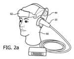
トランスデューサアレイ10a及び10bは、頭部の両側から患者の頭蓋内へと超音波を送信するが、頭部の前部又は頭蓋骨の背部の後頭下の音響窓といった他の場所を使用してもよい。大多数の患者の頭部の側部が、頭部の両側の耳の周り又は上方の側頭骨における経頭蓋超音波検査に適した音響窓を有利に提供する。様々な身体部分に適用される他の超音波治療とは対照的に、頭蓋骨において適切な音響窓を提供するアクセス面積は限られている。本発明は、皮膚表面における瞬時音響出力を有利に低減し、これにより、患者の安全性を向上させる。これらの音響窓を介してエコーを送受信するために、トランスデューサアレイは、これらの場所において、優れた音響的接触状態になければならないが、これは、トランスデューサアレイを頭部に対してヘッドセットで保持することにより行われる。例えば図2aは、マネキン人形の頭部60に取り付けられた2つのマトリクスアレイプローブ10用のヘッドセット62を示す。大多数の患者の頭部の側部は、頭部の両側の耳の周り及び耳の前の側頭骨における経頭蓋超音波検査に適した音響窓を有利に提供する。これらの音響窓を介してエコーを送受信するために、トランスデューサアレイは、これらの場所において、優れた音響的接触状態になければならないが、これは、トランスデューサアレイを頭部に対してヘッドセット62で保持することにより行われる。ヘッドセットは、トランスデューサアレイがその共形接触面によって操作されることを可能にし、脳内の動脈に向けられる一方で、側頭部窓に対する音響的接触を維持するスナップ式の変形可能な音響スタンドオフ44を有する。図示されるプローブ10は、プローブハンドルを90°曲げることによって湾曲され、これにより、プローブは、その重力中心が頭部及びヘッドセットに近づくので、ヘッドセット62に取り付けられるとより安定する。音響的結合は、プローブハンドルに嵌合球面を組み込むことによって容易にされる。これは、プローブが、患者の側頭部窓にしっかりと結合されるまで、ヘッドセット62内でピボットすることを可能にする。The
図2は、頭蓋骨100を走査するように音響結合されると、マトリクスアレイトランスデューサ10a及び10bによって走査されるボリュメトリック画像フィールド102、104を示す。臨床医は、これらのボリュメトリック画像フィールドにおける頭蓋血管系を撮像し、頭蓋血流を妨げている血栓を見つけ出すべく様々な方向にピラミッド形状の画像フィールドをステアリングすることができる。画像フィールド102、104の各位置において、臨床医は、ディスプレイ上のリアルタイム画像内の血流の障害物を探すか、又は、頭蓋血管系の画像若しくはマップを捕捉(フリーズ)することができる。血管マップが取得され、静的に保持されると、画像は、画像の分解能又はスケールを向上するように高度処理(例えば合成、信号平均化)され、また、画面上で操作され、血管閉塞の詳細な探査において、様々な点及び様々な視野から注意深く調べられる。このように、臨床医は狭窄症と診断することができる。臨床医は、血管マップを調べて血流経路における障害の形跡が見つけられなければ、画像フィールドを頭蓋の別の領域にステアリングして、別の画像フィールドの血管マップを調べる。臨床医は、血管マップのドップラーデータ又は超音波システムのスペクトルドップラー機能を使用して、頭蓋血管系内の特定の位置において流速測定を行うことができる。次に、超音波システムのレポート生成機能を使用して、測定値を記録し、診断のレポートを作成する。2 shows the volumetric image fields 102, 104 scanned by the
臨床医が狭窄部を発見した場合、超音波ビームで血栓を溶解させるように、狭窄部のある部位においてVARを適用する本発明の方法により治療が提供可能である。臨床医は、超音波システムの「治療」モードを作動させると、治療超音波ビームのベクトル経路を示すグラフィック110、112が画像フィールド102、104内に出現する。治療超音波ビームは、ベクトルグラフィック110又は112が血栓部位に合焦するまで、ユーザインターフェース38を制御することによって操作される。以下に説明される本開示の実施態様では、治療ビームは、臨床医がベクトルグラフィックを向けた血栓周辺においてパターンで自動的に走査される。治療ビームは、細く集束された収束ビーム、又は、ペンシルビームと知られている比較的長い焦点距離を有するビームであってよい。治療ビーム用に生成されるエネルギーは、診断超音波に許可されている超音波レベルを上回り、この場合、血栓部位におけるVARが効果的に破壊される。任意の特定の科学的理論に縛られるつもりはないが、結果として生じるVAR破裂のエネルギーが、血栓に効果的に作用し、血栓を破壊する傾向があり、血栓を血流内に溶解させると仮定する。しかし、診断エネルギーレベルにおけるVARの超音波照射でも、血栓の溶解に十分である場合もある。If the clinician finds a stenosis, treatment can be provided by the method of the present invention, which applies VAR at the site of the stenosis so that the ultrasound beam dissolves the clot. The clinician activates the "treatment" mode of the ultrasound system, and
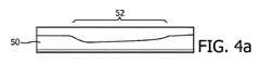
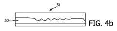
図3は、超音波血栓溶解に使用される典型的な集束超音波治療ビーム領域の横断面の圧力レベルプロファイルのプロットである。プロットの線は、様々な圧力レベルにおける集束ビーム直径を示す。超音波場内のVAR、具体的には、微小気泡は、50~100kPaの比較的中程度の圧力によって素早く破壊されるが、超音波場内に残り続ける限り、通常は、数十ミリ秒の間、治療血栓溶解のために治療的に有効であり続ける。しかし、ビームが、治療効果があるように十分な振幅(通常は200~400kPaのピーク圧力)を有すると、ビームに近接するVARは、治療効果に寄与することなく、ビームの両側における減少した振幅によって破壊される。この影響により、血栓の周りのより大きい治療ボリュームに亘って超音波ビームをステアリングする際に、幾つかの不所望の結果が生じる可能性がある。ビームがステアリングされて互いの間隔が近くになり過ぎると、連続ビームによる治療効果が減少する。これは、図4aに示される血栓の図によって説明される。図4aは、52に示されるように、血栓の上部に沿って左から右へと送られた一連の治療ビームからなる治療ビームパターンによって溶解されたある長さのインビトロ血栓50を示す。図示されるように、パターンの初期治療ビームは、左側で血栓を深くまで破壊するのに効果的であるが、初期治療ビーム付近における不所望の微小気泡の破壊によって微小気泡が減少することにより、走査が右側へと進むにつれて、残る有効な微小気泡の数が少なくなる。結果として、範囲が示された領域の右側では、血栓は浅い深度までしか溶解されないことが分かる。しかし、この影響を回避するために、個々のビームが離れ過ぎていると、結果として、血栓の治療ビーム照射が不十分となり、図4bの54に示されるように、血栓のスカロッピングがもたらされる。本開示のシステム及び方法は、図4cの56に示されるように、これら両方の不所望の結果を阻止するのに効果的である。Figure 3 is a plot of pressure level profiles across a typical focused ultrasound therapeutic beam region used for ultrasound thrombolysis. The lines in the plot indicate the focused beam diameter at various pressure levels. VARs within the ultrasound field, specifically microbubbles, are quickly destroyed by relatively moderate pressures of 50-100 kPa, but remain therapeutically effective for therapeutic thrombolysis as long as they remain within the ultrasound field, typically for tens of milliseconds. However, once the beam has sufficient amplitude to be therapeutically effective (typically 200-400 kPa peak pressure), VARs close to the beam are destroyed by the reduced amplitude on either side of the beam without contributing to the therapeutic effect. This effect can produce several undesirable results when steering an ultrasound beam over a larger treatment volume around a thrombus. If the beams are steered too close together, the therapeutic effect of successive beams is reduced. This is illustrated by the diagram of a thrombus shown in Figure 4a. FIG. 4a shows a length of in vitro
本開示の原理によれば、超音波血栓溶解中のVARの時期尚早な/不所望の破壊による上記スカロッピング及び治療効果減少を回避する幾つかの独自の治療ビーム走査フォーマットが説明される。これらの走査フォーマットは、通常、不所望な微小気泡破壊を制限するのに十分に広い集束超音波ビーム間隔を有する2つ以上の独自の走査パターンを連続的に使用することからなる。治療ビームの送信は、効果的な治療送達に必要とされる十分に高いVAR濃度の存在を確実とするために、各走査パターン間に十分に長いVAR補充時間をおいて、大域的且つ均一的な血栓カバレッジを依然としてもたらすように、時間的にインターリーブされる。各走査パターンは、通常は不所望のVAR破壊を制限するのに十分に広い集束超音波ビーム間隔を有する。発明者の研究によって、400kPaのピーク圧ビームでは、ビーム間隔は、好適には、少なくとも電力半値ビーム幅(half-power beam width)(最大ビーム圧の約70%に相当)の大きさであり、理想的には、約100kPa~圧力半値ビーム幅(half-pressure beam width)であるが、75~100kPa(18.75%~25%)圧力ビーム幅未満であるべきことが示された(図3参照)。VAR(具体的には微小気泡)をその焦点ゾーンにおいて400kPaで超音波照射するように設定される1MHzにおける典型的な集束超音波血栓溶解治療超音波ビームでは、このビーム間隔は、おおよそ2.6mm(電力半値ビーム幅のサイズ)~3.6mm(圧力半値ビーム幅のサイズ)又は5.2mmの範囲である。 According to the principles of the present disclosure, several unique therapeutic beam scanning formats are described that avoid the above-mentioned scalloping and therapeutic efficacy reduction due to premature/unwanted destruction of VAR during sonothrombolysis. These scanning formats typically consist of the sequential use of two or more unique scanning patterns with focused ultrasound beam spacings wide enough to limit undesired microbubble destruction. The transmission of the therapeutic beams is interleaved in time to still provide global and uniform thrombus coverage, with a sufficiently long VAR replenishment time between each scanning pattern to ensure the presence of a sufficiently high VAR concentration required for effective therapy delivery. Each scanning pattern typically has a focused ultrasound beam spacing wide enough to limit undesired VAR destruction. The inventors' studies have shown that for a peak pressure beam of 400 kPa, the beam spacing should preferably be at least as large as the half-power beam width (corresponding to about 70% of the maximum beam pressure) and ideally be about 100 kPato half-pressure beam width, but less than 75-100 kPa (18.75%to 25%) pressure beam width (see FIG. 3). For a typical focused ultrasound thrombolysis therapy ultrasound beam at 1 MHz set to insonify the VARs (specifically the microbubbles) at 400 kPa in their focal zone, this beam spacing is in the range of approximately 2.6 mm (the size of the half-power beam width)to 3.6 mm (the size of the half-pressure beam width) or 5.2 mm.
本開示に従った使用に適したビーム走査パターンは、血栓ボリューム全体及び周囲組織に亘って順次的に送信される個々の集束ビームの集まりから構成され、これにより、適切な処理マージンが確保される。典型的な脳血栓は、閉塞血管の内径に相当する直径(中大脳動脈の場合2~5mm)と最大で数センチの長さを有する円筒形である。血栓とその周囲組織との徹底的な超音波照射を達成するために、各走査パターンは、好適には1~5cm2の典型的な断面積に及ぶ。これは、各走査パターンが、所望のビーム間隔及び標的領域カバレッジを所与として、多くのビームからなることを意味する。ビームの重なりと、隣接ビームにより結果として生じるVAR破壊とを更に最小限に抑えるために、各連続走査パターンのビームは、先行パターンのビーム間に、インターリーブされて配置される。2ビームシーケンス、3ビームシーケンス、4ビームシーケンス又は5ビームシーケンスといった様々なビームパターンシーケンスが使用されてよい。シーケンスにおけるすべてのビームパターンが異なっても、ビームパターンのうちの幾つかが同じであってもよい。 Beam scanning patterns suitable for use according to the present disclosure consist of a collection of individual focused beams transmittedsequentially throughout the thrombus volume and surrounding tissue, ensuring adequate treatment margins. A typical cerebral thrombus is cylindrical with a diameter corresponding to the inner diameter of the occluded vessel (2-5 mm for the middle cerebral artery) and a length of up to several centimeters. To achieve thorough insonification of the thrombus and its surrounding tissue, each scanning pattern preferably spans a typical cross-sectional area of 1-5 cm2. This means that each scanning pattern consists of many beams, given the desired beam spacing and target area coverage. To further minimize beam overlap and the resulting VAR destruction caused by adjacent beams, the beams of each successive scanning pattern are interleaved between the beams of the previous pattern. Various beam pattern sequences may be used, such as a two-beam sequence, a three-beam sequence, a four-beam sequence or a five-beam sequence. All beam patterns in a sequence may be different or some of the beam patterns may be the same.
図5a及び図5bは、例示的なビームパターンシーケンスにおいて送信された2つの例示的なビームパターンを示す。これらの図面は、血栓の場所における横断面において軸方向に見たビーム70を示す。外側の円は半圧ビームプロファイルの限界を定め、小さい円はピーク圧ビーム軸の限界を定める。ビームの相対位置と、ビームのビーム幅とは、隣接ビーム内の造影剤との干渉への影響を低減するように調整される。例えば図5a及び図5bにおけるビームの外側の円は重なり合わず、隣接ビームがビーム焦点領域外のVAR、即ち、微小気泡を破裂させないように離間されている。様々なビームパターンが使用されてよい。例えばX×Yマトリクスビームを使用することができ、また、様々な数のビームを選択することもできる。幾つかの実施形態では、使用されるビーム数は、例えば5~50、10~30又は10~20に及ぶ。図5a~図5dでは、各ビームパターンは、この例では約1平方センチメートルの断面積に及ぶ4×3マトリクスに配置された8つの個別に送信され、集束されたビームからなる。この例では、中心間ビーム間隔は2.6mmである。図5a~図5dの走査パターンのビームは空間的にインターリーブされ、したがって、1つの走査パターンが、他の走査パターン間の空間を埋めることが分かる。 Figures 5a and 5b show two exemplary beam patterns transmitted in an exemplary beam pattern sequence. These figures show the
図5a~図5dの走査パターンは、必要に応じて、送信されたビームパターン間に補充期間又は時間間隔を有する4パターンシーケンスで送信される。血栓領域は、最初に、図5aのパターンにおけるビームで走査され、次に、ビーム間間隔の半分(約1.3mm)だけ図5aのパターンから左にオフセットされている図5bのビームで走査される。次に、図5aのビームパターンが再び送信されるが、ビーム間間隔の半分(約1.3mm)だけ図5aのビームパターンから垂直方向にオフセットされている。次に、これもビーム間間隔の半分だけ図5bのビームパターンから垂直方向にオフセットされている図5bのビームパターンで走査される。標的治療ボリュームに超音波照射するように各走査パターンが実行された後、新しいVARが治療領域に補充されるように、数秒(通常は2秒)の中断があり、その後、次の走査パターンが実行される。図5eに示されるように、4つの連続走査パターンの完了後、音響的に、血栓標的は実質的に均一な超音波場に晒される。
The scan patterns of Figures 5a- 5d are transmitted in a four-pattern sequence with a replenishment period or time interval between the transmitted beam patterns, as required. The thrombus region is first scanned with the beam in the pattern of Figure 5a, then with the beam of Figure 5b, which is offset to the left from the pattern of Figure 5a by half the inter-beam spacing (about 1.3 mm). Next, the beam pattern of Figure 5a is transmitted again, but offset vertically from the beam pattern of Figure 5a by half the inter-beam spacing (about 1.3 mm). Next, it is scanned with the beam pattern of Figure 5b, which is also offset vertically from the beam pattern of Figure 5b by half the inter-beam spacing. After each scan pattern is performed to insonify the target treatment volume, there is a pause of a few seconds (usually 2 seconds) to allow new VARs to replenish the treatment region, and then the next scan pattern is performed. After the completion of four consecutive scan patterns, acoustically, the thrombus target is exposed to a substantially uniform ultrasound field, as shown in Figure 5e.
図6は、本開示による別の4パス走査シーケンスの数値例である。このシーケンスでは、第1のビームパターンのビーム「1」は、グリッドの第1、第3及び第5の横列に沿って水平方向に離間されている。グリッド位置「2」によって表される第2のビームパターンは、第2及び第4の横列において水平方向に離間され、第1のパターンのビーム間で対角線上に配置される。第3のパターンのビーム「3」は、第1、第3及び第5の横列における第1のパターンのビームによって走査されなかった空間を埋め、また、第2のビームパターンのビーム間で垂直方向に埋める。第4のビームパターンのビーム「4」は、第1のビームパターンのビーム間を垂直方向に、また、第2のビームパターンのビーム間を水平方向に埋めることが分かる。結果として、グリッド領域、したがって、ビームによって横断されるボリュームの完全な超音波照射がもたらされる。図4cは、図6のビームパターンを用いた血栓溶解から生じる所望の均一血栓溶解プロファイルを示す。6 is a numerical example of another four-pass scanning sequence according to the present disclosure. In this sequence, beams "1" of a first beam pattern are horizontally spaced along the first, third and fifth rows of the grid. A second beam pattern, represented by grid position "2", is horizontally spaced in the second and fourth rows and is diagonally located between the beams of the first pattern. Beams "3" of a third pattern fill the space not scanned by the beams of the first pattern in the first, third and fifth rows and also fill vertically between the beams of the second beam pattern. It can be seen that beams "4" of a fourth beam pattern fill vertically between the beams of the first beam pattern and horizontally between the beams of the second beam pattern. The result is complete insonification of the grid area and therefore the volume traversed by the beams. FIG. 4c shows the desired uniform thrombolysis profile resulting from thrombolysis using the beam pattern of FIG. 6.
図7に、図6と同じグリッド及びボリュームの3パス走査シーケンスが示される。第1のビームパターンのビーム「1」は、2つのグリッド位置だけ水平方向に、1つのグリッド位置だけ垂直方向に離間されて交互配列で送信される。第2のビームパターンのビーム「2」も、2つのグリッド位置だけ水平方向に、1つのグリッド位置だけ垂直方向に離間されて第1のビームパターンからオフセットされるパターンで同様に送信される。第3のグリッドパターンのビーム「3」は、第1及び第2のビームパターンとは異なるパターンでオフセットされ、ここでも、互いから、2つのグリッド位置だけ水平方向に、1つのグリッド位置だけ垂直方向に離間されてグリッドの残りの位置を埋める。この3パスビームパターンシーケンスも、グリッド領域全体に超音波照射することが分かるが、不所望な隣接VAR破壊を回避し、したがって、これらのVARが後続のビームパターンによって効果的に治療的に破壊できるように各パターンのビームは間隔があけられている。前の例と同様に、血栓位置への新しいVARの流入を可能とするように、リフレッシュ時間が連続パターン間に許容されている。7 shows a three-pass scan sequence of the same grid and volume as in FIG. 6. Beams "1" of the first beam pattern are transmitted in an alternating arrangement, spaced two grid positions horizontally and one grid position vertically. Beams "2" of the second beam pattern are similarly transmitted in a pattern offset from the first beam pattern, spaced two grid positions horizontally and one grid position vertically. Beams "3" of the third grid pattern are offset in a different pattern from the first and second beam patterns, again spaced two grid positions horizontally and one grid position vertically from each other to fill in the remaining positions of the grid. It can be seen that this three-pass beam pattern sequence also insonifies the entire grid area, but the beams of each pattern are spaced apart to avoid undesired adjacent VAR destruction so that these VARs can be effectively therapeutically destroyed by the subsequent beam pattern. As in the previous example, refresh time is allowed between successive patterns to allow for the influx of new VARs to the thrombus location.
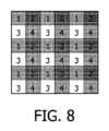
図8は、本開示に使用可能であるビームパターンの別の例を示す。「1」と示されるビームが最初に走査される4ビーム走査シーケンスが示される。例えば2秒である待機時間後、「2」と示されるビームが走査され、その次に、「3」と示されるビームが走査され、「4」と示されるビームが走査される。Figure 8 shows another example of a beam pattern that can be used in the present disclosure. A four-beam scanning sequence is shown in which the beam labeled "1" is scanned first. After a waiting period, e.g., 2 seconds, the beam labeled "2" is scanned, followed by the beam labeled "3" and then the beam labeled "4".
当然ながら、ブロック図の各ブロック、ブロック図におけるブロックの組み合わせ、並びに、本明細書に開示されるシステム及び方法の任意の部分が、コンピュータプログラム命令によって実施可能である。これらのプログラム命令は、プロセッサ上で実行する命令が、ブロック図の1つ以上のブロックに指定される又は本明細書に開示されるシステム及び方法について説明される動作を実施する手段を作成するようにマシンを生成するように、プロセッサに提供される。コンピュータプログラム命令は、コンピュータ実施処理を生成するために、一連の動作ステップをプロセッサによって行わせるプロセッサによって実行される。コンピュータプログラム命令は更に、動作ステップの少なくとも一部を並列に行わせる。更に、ステップの幾つかは、マルチプロセッサコンピュータシステムにおいて起きるように、2つ以上のプロセッサにわたって行われる。更に、1つ以上の処理は、他の処理と同時に行われるか、又は、開示の範囲若しくは精神から逸脱することなく、示されるシーケンスとは異なるシーケンスにおいて行われる。コンピュータプログラム命令は、RAM、ROM、EEPROM、フラッシュメモリ若しくは他のメモリ技術、CD-ROM、デジタルバーサタイルディスク(DVD)若しくは他の光学ストレージ、磁気カセット、磁気テープ、磁気ディスクストレージ若しくは他の磁気ストレージデバイス、又は、所望の情報を記憶するのに使用可能でありコンピュータデバイスによってアクセス可能である任意の他の媒体を含むが、これらに限定されない。Of course, each block of the block diagram, combinations of blocks in the block diagram, and any portion of the systems and methods disclosed herein can be implemented by computer program instructions. These program instructions are provided to a processor such that the instructions, which execute on the processor, create a machine to create means for performing the operations specified in one or more blocks of the block diagram or described in the systems and methods disclosed herein. The computer program instructions are executed by the processor to cause the processor to perform a sequence of operational steps to generate a computer-implemented process. The computer program instructions further cause at least some of the operational steps to be performed in parallel. Furthermore, some of the steps are performed across two or more processors, such as occurs in a multiprocessor computer system. Furthermore, one or more processes may be performed simultaneously with other processes or in a different sequence than shown without departing from the scope or spirit of the disclosure. The computer program instructions may be stored in, but are not limited to, RAM, ROM, EEPROM, flash memory or other memory technology, CD-ROM, digital versatile disk (DVD) or other optical storage, magnetic cassettes, magnetic tape, magnetic disk storage or other magnetic storage devices, or any other medium usable to store the desired information and accessible by a computing device.
本発明による方法において有用な血管音響共振器は、伝搬媒体における音圧をミクロンサイズの変位に変換可能であり、ミクロンサイズの変形振幅を用いて血栓又は血管壁に変形を印加可能である任意の化学成分を含む。適切なVARの好適な例は、ガス入り微小胞、即ち、内部に適切なガスを含む安定化エンベロープを含むナノ又はミクロンサイズの小胞を含む。VARの処方設計及び調合は、当業者にはよく知られている。例えば国際特許公開WO91/15244、米国特許第5,686,060号(Schneider他)及び国際特許公開WO2004/069284に説明されるように、リン脂質を含むエンベロープを有する微小気泡や、例えば米国特許第5,711,933号に説明されるポリマーを含むエンベロープを有するマイクロバルーンや、例えば米国特許第6,333,021号に説明されるように、生分解性の不水溶性脂質を含むエンベロープを有するマイクロカプセルの処方設計及び調合が含まれる。好適には、安定化エンベロープは、両親媒性の物質を含み、より好適にはリン脂質を含む。好適なリン脂質は、脂肪酸の1つ又は好適には2つの(同じ又は異なる)残基及びリン酸を有するグリセロールのエステルを含む。リン酸残基は、次に、親水基に結合する。他の好適なリン脂質は、ホスファチジン酸、即ち、脂肪酸を有するグリセロール-リン酸のジエステルを含む。特に好適なリン脂質は、ホスファチジルコリン、エチルホスファチジルコリン、ホスファチジルグリセロール、ホスファチジン酸、ホスファチジルエタノールアミン、ホスファチジルセリン、ホスファチジルイノシトール又はスフィンゴミエリンの脂肪酸ジエステルである。ペグ化されたリン脂質を含むポリマー改質リン脂質も、微小気泡の安定化エンベロープを形成するために有利に使用される。任意の生体適合ガス、ガス前駆体又はこれらの混合物を用いて、上記微小胞を充填してよい。フッ素化ガス、具体的にはパーフルオロ化ガスが好まれる。特に好適なガスは、例えば米国特許第6,881,397号及び第5,556,610号に説明されるように、SF6、C3F8、C4F10又はこれらの混合体であり、任意選択的に、空気、酸素、窒素、二酸化炭素又はこれらの混合物が混合される。 Vascular acoustic resonators useful in the method according to the invention include any chemical moiety capable of converting acoustic pressure in a propagation medium into micron-sized displacements and applying deformations to the thrombus or vessel wall with micron-sized deformation amplitudes. Suitable examples of suitable VARs include gas-filled microvesicles, i.e. nano- or micron-sized vesicles with a stabilizing envelope containing a suitable gas inside. The formulation and preparation of VARs are well known to those skilled in the art. They include microbubbles with an envelope containing phospholipids, e.g. as described in International Patent Publication WO 91/15244, U.S. Patent No. 5,686,060 (Schneider et al.) and International Patent Publication WO 2004/069284, microballoons with an envelope containing polymers, e.g. as described in U.S. Patent No. 5,711,933, and microcapsules with an envelope containing biodegradable water-insoluble lipids, e.g. as described in U.S. Patent No. 6,333,021. Preferably, the stabilizing envelope comprises an amphiphilic substance, more preferably a phospholipid. A preferred phospholipid comprises an ester of glycerol with one or preferably two (same or different) residues of a fatty acid and a phosphoric acid. The phosphoric acid residue is then bonded to a hydrophilic group. Another preferred phospholipid comprises phosphatidic acid, i.e. a diester of glycerol-phosphoric acid with a fatty acid. Particularly preferred phospholipids are fatty acid diesters of phosphatidylcholine, ethylphosphatidylcholine, phosphatidylglycerol, phosphatidic acid, phosphatidylethanolamine, phosphatidylserine, phosphatidylinositol or sphingomyelin. Polymer-modified phospholipids, including PEGylated phospholipids, are also advantageously used to form the stabilizing envelope of the microbubbles. Any biocompatible gas, gas precursor or mixtures thereof may be used to fill the microvesicles. Fluorinated gases, in particular perfluorinated gases, are preferred. Particularly suitable gases areSF6 ,C3F8 ,C4F10 , or mixtures thereof, optionally mixed with air, oxygen, nitrogen, carbon dioxide, or mixtures thereof, as described, for example, in U.S. Pat. Nos. 6,881,397 and5,556,610.
VARの安定化エンベロープを形成する化学成分は、任意選択的に、他の賦形剤と混合されて、所望のガスと接触する乾燥残留物として保管される。微小胞は、通常、ガスの存在下で、優しく振動して、乾燥残留物を水性担体(例えば生理食塩水又はグルコース溶液)に接触させる。これにより、微小胞の水性懸濁液が得られる。微小胞懸濁液は、次に、通常は、注射によって、好適には静脈内投与される。The chemical components that form the stabilizing envelope of the VAR are optionally mixed with other excipients and stored as a dry residue that is contacted with the desired gas. The microvesicles are typically gently agitated in the presence of the gas to contact the dry residue with an aqueous carrier (e.g., saline or glucose solution). This results in an aqueous suspension of the microvesicles. The microvesicle suspension is then typically administered by injection, preferably intravenously.
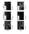
図9a及び図9bは、ラットに行われた実験結果を示す。図面は、治療群(b)及び対照(未治療)群(a)について、血管音響共振器を含み、複数の連続パターンで治療ビームを用いて超音波照射された小塞栓が形成されたラットの後肢のコントラスト増強超音波画像を示す。当物生体において、ラットの後肢のかん流が、超音波臨床システム(Sequioi512)と超音波造影剤(SonoVue(商標))とを使用してコントラスト増強超音波撮像(CEUS)を行う基準の図9(a1)及び図9(b1)においてアクセスされる。自己移植微小血栓の懸濁液が、大腿動脈に注入され、10分後、CEUSを行い、成功した閉塞が評価された。閉塞が成功したことは、図9(a2)及び図9(b2)に示される超音波画像内にコントラスト増強がないことにより明らかとなる。30分後、図9(a3)によって表される対照群ではかん流は見られなかった。VARと組み合わされた超音波治療ビームでラットの後肢を治療した30分後、図9(b3)に示されるように、治療群の再かん流が明らかとなった。図5において説明されたパターンと同様の複数の連続パターンで送信された超音波ビームパターンは、4×3マトリクスに配置される12の個々に送信され集束されたビームを含む。これらの実験に使用される中心間ビーム間隔は2.6mmであり、最大ピーク圧は400kPaであった。再かん流は、半定量的等級付けを使用して等級付けられた(0:再かん流なし、1:最小、2:部分的、3:完全)。9a and 9b show the results of an experiment performed on rats. The figures show contrast-enhanced ultrasound images of the hind limbs of rats in which small emboli were formed, including a vascular acoustic resonator, and insonified with a treatment beam in multiple sequential patterns, for the treatment group (b) and the control (untreated) group (a). In vivo, the perfusion of the rat's hind limbs is accessed in Figs. 9(a1) and 9(b1) on the basis of contrast-enhanced ultrasound imaging (CEUS) using an ultrasound clinical system (Sequio 512) and an ultrasound contrast agent (SonoVue™). A suspension of autologous microthrombi was injected into the femoral artery, and after 10 minutes, CEUS was performed to assess successful occlusion. Successful occlusion is evident by the absence of contrast enhancement in the ultrasound images shown in Figs. 9(a2) and 9(b2). After 30 minutes, no perfusion was seen in the control group represented by Fig. 9(a3). Thirty minutes after treating the rat hind limbs with the ultrasound treatment beam combined with VAR, reperfusion was evident in the treatment group, as shown in FIG. 9(b3). The ultrasound beam pattern, transmitted in multiple sequential patterns similar to that described in FIG. 5, included 12 individually transmitted and focused beams arranged in a 4×3 matrix. The center-to-center beam spacing used in these experiments was 2.6 mm, and the maximum peak pressure was 400 kPa. Reperfusion was graded using a semi-quantitative grading system (0: no reperfusion, 1: minimal, 2: partial, 3: complete).
Claims (10)
Translated fromJapanese前記関心領域内へと、前記血管音響共振器(VAR)を破裂又は破壊するのに適した前記超音波治療ビームを送信する超音波アレイと、
前記超音波アレイに結合され、複数のインターリーブされたパターンで前記超音波治療ビームのステアリングを制御する送信コントローラと、
を含み、
時間的に後続する各パターンは、前記関心領域の均一且つ十分な照射を提供するように、前のパターンのビーム領域間に空間的にインターリーブされるビーム領域を含み、
前記送信コントローラは、前記超音波システムに、2つのインターリーブされたパターンの送信間の少なくとも0.1秒の時間間隔における送信をやめさせ、
前記超音波治療ビームの任意のパターンにおける前記ビーム領域の中心は、電力半値ビーム幅と18.75%の圧力ビーム幅との間の範囲内にある間隔だけ互いから離されていて、
前記複数のインターリーブされたパターンは、
所定の間隔に従って、互いから空間によって離されている前記超音波治療ビームの第1のビームパターンと、
前記第1のビームパターンの前記超音波治療ビームを互いから離す前記空間へとステアリングされる前記超音波治療ビームの第2のビームパターンと、
を含む、超音波システム。 1. An ultrasound systemfor insonifying a region of interest, including a vascular acoustic resonator(VAR) , with a spatially interleaved pattern of ultrasoundtreatment beams, comprising:
an ultrasound array for transmitting the ultrasound treatment beam into the region of interest,the ultrasound treatment beam being adapted to disrupt or destroy the vascular acoustic resonator(VAR) ;
a transmit controller coupled to the ultrasound array tocontrol steering of the ultrasound treatment beamsin a plurality of interleaved patterns ;
Including,
each successive pattern in time includes beam regions that are spatially interleaved between beam regions of a previous pattern to provide uniform and sufficient illumination of the region of interest;
the transmit controller causes the ultrasound system to cease transmitting in a time interval of at least 0.1 seconds between the transmission of two interleaved patterns;
the centers of the beam areas in any pattern of the ultrasound treatment beam are spaced apart from one another by a distance that is in a range between half-power beamwidth and 18.75% pressure beamwidth;
The plurality of interleaved patterns include:
first beam patterns of the ultrasound treatment beams spaced apart from one another according to a predetermined interval;
a second beam pattern of the ultrasound treatment beams steered into the space to move the ultrasound treatment beams of the first beam pattern away from each other;
2. An ultrasound systemcomprising :
前記超音波治療ビームの第2のパターンは、前記超音波治療ビームが、前記第1のパターンの前記超音波治療ビーム間で水平方向及び垂直方向に空間的にインターリーブされ、
前記複数のインターリーブされたパターンは、前記第1のパターン及び前記第2のパターンの前記超音波治療ビーム間で水平方向及び垂直方向に空間的にインターリーブされている前記超音波治療ビームの第3のパターンを有する、請求項1に記載の超音波システム。The first pattern of ultrasound treatment beams includes ultrasound treatment beamsspaced horizontally and vertically from one another;
the second pattern of ultrasound treatment beams is spatiallyinterleaved horizontally and vertically between the ultrasound treatment beams of the first pattern;
10. The ultrasound system of claim 1, wherein the multiple interleaved patterns include a thirdpattern of the ultrasound treatment beams that are horizontally and vertically spatially interleaved between the ultrasound treatment beams of the first and second patterns.
前記第1のパターン、前記第2のパターン及び前記第3のパターンの前記超音波治療ビーム間で水平方向及び垂直方向に空間的にインターリーブされている前記超音波治療ビームの第4のパターンを含む、請求項9に記載の超音波システム。The plurality of interleaved patterns further comprises:
10. The ultrasound system of claim 9, including a fourth pattern of ultrasound treatment beams that are horizontally and vertically spatially interleaved between the ultrasound treatment beams of the first pattern, the second pattern, and the third pattern.
Priority Applications (1)
| Application Number | Priority Date | Filing Date | Title |
|---|---|---|---|
| JP2022202120AJP2023036759A (en) | 2015-12-09 | 2022-12-19 | Interleaved beam pattern for sonothrombolysis and other vascular acoustic resonator mediated therapy |
Applications Claiming Priority (5)
| Application Number | Priority Date | Filing Date | Title |
|---|---|---|---|
| US201562265154P | 2015-12-09 | 2015-12-09 | |
| US62/265,154 | 2015-12-09 | ||
| EP16155298 | 2016-02-11 | ||
| EP16155298.9 | 2016-02-11 | ||
| PCT/EP2016/080127WO2017097853A1 (en) | 2015-12-09 | 2016-12-07 | Interleaved beam pattern for sonothrombolysis and other vascular acoustic resonator mediated therapies |
Related Child Applications (1)
| Application Number | Title | Priority Date | Filing Date |
|---|---|---|---|
| JP2022202120ADivisionJP2023036759A (en) | 2015-12-09 | 2022-12-19 | Interleaved beam pattern for sonothrombolysis and other vascular acoustic resonator mediated therapy |
Publications (3)
| Publication Number | Publication Date |
|---|---|
| JP2018538056A JP2018538056A (en) | 2018-12-27 |
| JP2018538056A5 JP2018538056A5 (en) | 2021-04-15 |
| JP7534839B2true JP7534839B2 (en) | 2024-08-15 |
Family
ID=55361368
Family Applications (2)
| Application Number | Title | Priority Date | Filing Date |
|---|---|---|---|
| JP2018529202AActiveJP7534839B2 (en) | 2015-12-09 | 2016-12-07 | Interleaved beam patterns for sonothrombolysis and other therapies via vascular acoustic resonators |
| JP2022202120APendingJP2023036759A (en) | 2015-12-09 | 2022-12-19 | Interleaved beam pattern for sonothrombolysis and other vascular acoustic resonator mediated therapy |
Family Applications After (1)
| Application Number | Title | Priority Date | Filing Date |
|---|---|---|---|
| JP2022202120APendingJP2023036759A (en) | 2015-12-09 | 2022-12-19 | Interleaved beam pattern for sonothrombolysis and other vascular acoustic resonator mediated therapy |
Country Status (7)
| Country | Link |
|---|---|
| US (1) | US11284910B2 (en) |
| EP (1) | EP3386589B1 (en) |
| JP (2) | JP7534839B2 (en) |
| CN (1) | CN108601948B (en) |
| BR (1) | BR112018011456B1 (en) |
| CA (1) | CA3007514C (en) |
| WO (1) | WO2017097853A1 (en) |
Families Citing this family (6)
| Publication number | Priority date | Publication date | Assignee | Title |
|---|---|---|---|---|
| WO2016097867A2 (en) | 2014-12-19 | 2016-06-23 | Université Pierre Et Marie Curie (Paris 6) | Implantable ultrasound generating treating device for brain treatment, apparatus comprising such device and method implementing such device |
| US11253729B2 (en) | 2016-03-11 | 2022-02-22 | Sorbonne Universite | External ultrasound generating treating device for spinal cord and/or spinal nerve treatment, apparatus comprising such device and method |
| WO2017153798A1 (en) | 2016-03-11 | 2017-09-14 | Université Pierre Et Marie Curie (Paris 6) | Implantable ultrasound generating treating device for spinal cord and/or spinal nerve treatment, apparatus comprising such device and method |
| WO2019113538A2 (en)* | 2017-12-07 | 2019-06-13 | California Institute Of Technology | Methods and systems for noninvasive control of brain cells and related vectors and compositions |
| US11872085B2 (en)* | 2018-06-06 | 2024-01-16 | Insightec, Ltd. | Focused ultrasound system with optimized monitoring of cavitation |
| CN112370079B (en)* | 2020-11-18 | 2022-08-26 | 景德镇陶瓷大学 | Method for detecting thrombus by using ultrasonic Doppler |
Citations (2)
| Publication number | Priority date | Publication date | Assignee | Title |
|---|---|---|---|---|
| JP2003533263A (en) | 1997-10-27 | 2003-11-11 | ロバート ダブリュー クリブス | Lipolysis therapy and equipment |
| WO2015000953A1 (en) | 2013-07-03 | 2015-01-08 | Bracco Suisse S.A. | Devices and methods for the ultrasound treatment of ischemic stroke |
Family Cites Families (29)
| Publication number | Priority date | Publication date | Assignee | Title |
|---|---|---|---|---|
| US5556610A (en) | 1992-01-24 | 1996-09-17 | Bracco Research S.A. | Gas mixtures useful as ultrasound contrast media, contrast agents containing the media and method |
| IN172208B (en) | 1990-04-02 | 1993-05-01 | Sint Sa | |
| US5445813A (en) | 1992-11-02 | 1995-08-29 | Bracco International B.V. | Stable microbubble suspensions as enhancement agents for ultrasound echography |
| AU636481B2 (en) | 1990-05-18 | 1993-04-29 | Bracco International B.V. | Polymeric gas or air filled microballoons usable as suspensions in liquid carriers for ultrasonic echography |
| IL104084A (en) | 1992-01-24 | 1996-09-12 | Bracco Int Bv | Long-lasting aqueous suspensions of pressure-resistant gas-filled microvesicles their preparation and contrast agents consisting of them |
| US6333021B1 (en) | 1994-11-22 | 2001-12-25 | Bracco Research S.A. | Microcapsules, method of making and their use |
| US6013032A (en) | 1998-03-13 | 2000-01-11 | Hewlett-Packard Company | Beamforming methods and apparatus for three-dimensional ultrasound imaging using two-dimensional transducer array |
| US5997479A (en) | 1998-05-28 | 1999-12-07 | Hewlett-Packard Company | Phased array acoustic systems with intra-group processors |
| US6530885B1 (en) | 2000-03-17 | 2003-03-11 | Atl Ultrasound, Inc. | Spatially compounded three dimensional ultrasonic images |
| US6468216B1 (en) | 2000-08-24 | 2002-10-22 | Kininklijke Philips Electronics N.V. | Ultrasonic diagnostic imaging of the coronary arteries |
| US6723050B2 (en) | 2001-12-19 | 2004-04-20 | Koninklijke Philips Electronics N.V. | Volume rendered three dimensional ultrasonic images with polar coordinates |
| AU2003219843B2 (en) | 2002-02-20 | 2009-04-23 | Medicis Technologies Corporation | Ultrasonic treatment and imaging of adipose tissue |
| ES2352087T3 (en) | 2003-02-04 | 2011-02-15 | Bracco Suisse Sa | CONTRAST AGENTS FOR ULTRASOUND AND PROCEDURE FOR THE PREPARATION OF THE SAME. |
| PL1663394T3 (en) | 2003-09-08 | 2014-10-31 | Univ Arkansas | Ultrasound apparatus for augmented clot lysis |
| US7857773B2 (en)* | 2003-12-30 | 2010-12-28 | Medicis Technologies Corporation | Apparatus and methods for the destruction of adipose tissue |
| US20080234580A1 (en) | 2004-02-05 | 2008-09-25 | Koninklijke Philips Electronics, N.V. | Ultrasonic Imaging of Perfusion and Blood Flow with Harmonic Contrast Agents |
| US7806839B2 (en) | 2004-06-14 | 2010-10-05 | Ethicon Endo-Surgery, Inc. | System and method for ultrasound therapy using grating lobes |
| US20120165848A1 (en)* | 2010-08-02 | 2012-06-28 | Guided Therapy Systems, Llc | System and method for treating cartilage |
| US8357095B2 (en)* | 2005-10-20 | 2013-01-22 | The General Hospital Corporation | Non-invasive treatment of fascia |
| US20080262350A1 (en) | 2005-11-18 | 2008-10-23 | Imarx Therapeutics, Inc. | Ultrasound Apparatus and Method to Treat an Ischemic Stroke |
| US8235901B2 (en) | 2006-04-26 | 2012-08-07 | Insightec, Ltd. | Focused ultrasound system with far field tail suppression |
| WO2008018054A2 (en)* | 2006-08-08 | 2008-02-14 | Keter Medical Ltd. | Imaging system |
| CN101500651B (en) | 2006-08-11 | 2012-08-08 | 皇家飞利浦电子股份有限公司 | Ultrasound system for brain blood flow imaging and microbubble-enhanced clot lysis |
| US20080097206A1 (en)* | 2006-09-27 | 2008-04-24 | Chomas James E | Enhanced contrast agent augmented ultrasound thrombus treatment |
| US20100056924A1 (en)* | 2006-11-20 | 2010-03-04 | Koninklijke Philips Electronics N.V. | Control and display of ultrasonic microbubble cavitation |
| US20100160781A1 (en)* | 2008-12-09 | 2010-06-24 | University Of Washington | Doppler and image guided device for negative feedback phased array hifu treatment of vascularized lesions |
| JP2012519549A (en)* | 2009-03-04 | 2012-08-30 | ライポソニックス, インコーポレイテッド | Ultrasound treatment of adipose tissue at multiple depths |
| CA2973013C (en) | 2009-03-20 | 2023-01-24 | University Of Cincinnati | Ultrasound-mediated inducement, detection, and enhancement of stable cavitation |
| WO2014146022A2 (en)* | 2013-03-15 | 2014-09-18 | Guided Therapy Systems Llc | Ultrasound treatment device and methods of use |
- 2016
- 2016-12-07JPJP2018529202Apatent/JP7534839B2/enactiveActive
- 2016-12-07CNCN201680071995.8Apatent/CN108601948B/enactiveActive
- 2016-12-07CACA3007514Apatent/CA3007514C/enactiveActive
- 2016-12-07BRBR112018011456-1Apatent/BR112018011456B1/enactiveIP Right Grant
- 2016-12-07WOPCT/EP2016/080127patent/WO2017097853A1/ennot_activeCeased
- 2016-12-07EPEP16810307.5Apatent/EP3386589B1/enactiveActive
- 2016-12-07USUS15/780,248patent/US11284910B2/enactiveActive
- 2022
- 2022-12-19JPJP2022202120Apatent/JP2023036759A/enactivePending
Patent Citations (2)
| Publication number | Priority date | Publication date | Assignee | Title |
|---|---|---|---|---|
| JP2003533263A (en) | 1997-10-27 | 2003-11-11 | ロバート ダブリュー クリブス | Lipolysis therapy and equipment |
| WO2015000953A1 (en) | 2013-07-03 | 2015-01-08 | Bracco Suisse S.A. | Devices and methods for the ultrasound treatment of ischemic stroke |
Also Published As
| Publication number | Publication date |
|---|---|
| CN108601948B (en) | 2021-04-20 |
| CA3007514C (en) | 2024-03-19 |
| JP2023036759A (en) | 2023-03-14 |
| BR112018011456B1 (en) | 2024-01-09 |
| JP2018538056A (en) | 2018-12-27 |
| CN108601948A (en) | 2018-09-28 |
| US11284910B2 (en) | 2022-03-29 |
| CA3007514A1 (en) | 2017-06-15 |
| US20180353777A1 (en) | 2018-12-13 |
| WO2017097853A1 (en) | 2017-06-15 |
| EP3386589A1 (en) | 2018-10-17 |
| EP3386589B1 (en) | 2022-02-09 |
| BR112018011456A2 (en) | 2018-11-27 |
Similar Documents
| Publication | Publication Date | Title |
|---|---|---|
| JP7534839B2 (en) | Interleaved beam patterns for sonothrombolysis and other therapies via vascular acoustic resonators | |
| EP3016713B1 (en) | Devices for the ultrasound treatment of ischemic stroke | |
| US10363012B2 (en) | Ultrasound system for cerebral blood flow imaging and microbubble-enhanced blood clot lysis | |
| US8211023B2 (en) | Ultrasound system for cerebral blood flow monitoring | |
| US20080319356A1 (en) | Pulsed cavitational ultrasound therapy | |
| JP2009508649A (en) | Pulsed cavitation ultrasound therapy | |
| WO2012042423A1 (en) | Monitoring and control of microbubble cavitation in therapeutic ultrasound | |
| US20190069875A1 (en) | Ultrasound system for cerebral blood flow imaging and microbubble-enhanced blood clot lysis |
Legal Events
| Date | Code | Title | Description |
|---|---|---|---|
| A521 | Request for written amendment filed | Free format text:JAPANESE INTERMEDIATE CODE: A523 Effective date:20191205 | |
| A621 | Written request for application examination | Free format text:JAPANESE INTERMEDIATE CODE: A621 Effective date:20191205 | |
| A977 | Report on retrieval | Free format text:JAPANESE INTERMEDIATE CODE: A971007 Effective date:20201130 | |
| A131 | Notification of reasons for refusal | Free format text:JAPANESE INTERMEDIATE CODE: A131 Effective date:20201208 | |
| A524 | Written submission of copy of amendment under article 19 pct | Free format text:JAPANESE INTERMEDIATE CODE: A524 Effective date:20210305 | |
| A02 | Decision of refusal | Free format text:JAPANESE INTERMEDIATE CODE: A02 Effective date:20210719 | |
| A521 | Request for written amendment filed | Free format text:JAPANESE INTERMEDIATE CODE: A523 Effective date:20211118 | |
| C60 | Trial request (containing other claim documents, opposition documents) | Free format text:JAPANESE INTERMEDIATE CODE: C60 Effective date:20211118 | |
| C11 | Written invitation by the commissioner to file amendments | Free format text:JAPANESE INTERMEDIATE CODE: C11 Effective date:20211206 | |
| A521 | Request for written amendment filed | Free format text:JAPANESE INTERMEDIATE CODE: A821 Effective date:20211215 | |
| A911 | Transfer to examiner for re-examination before appeal (zenchi) | Free format text:JAPANESE INTERMEDIATE CODE: A911 Effective date:20220112 | |
| C21 | Notice of transfer of a case for reconsideration by examiners before appeal proceedings | Free format text:JAPANESE INTERMEDIATE CODE: C21 Effective date:20220114 | |
| A912 | Re-examination (zenchi) completed and case transferred to appeal board | Free format text:JAPANESE INTERMEDIATE CODE: A912 Effective date:20220304 | |
| C211 | Notice of termination of reconsideration by examiners before appeal proceedings | Free format text:JAPANESE INTERMEDIATE CODE: C211 Effective date:20220315 | |
| C22 | Notice of designation (change) of administrative judge | Free format text:JAPANESE INTERMEDIATE CODE: C22 Effective date:20220406 | |
| C13 | Notice of reasons for refusal | Free format text:JAPANESE INTERMEDIATE CODE: C13 Effective date:20220620 | |
| A601 | Written request for extension of time | Free format text:JAPANESE INTERMEDIATE CODE: A601 Effective date:20220916 | |
| A521 | Request for written amendment filed | Free format text:JAPANESE INTERMEDIATE CODE: A523 Effective date:20221219 | |
| A601 | Written request for extension of time | Free format text:JAPANESE INTERMEDIATE CODE: A601 Effective date:20230926 | |
| A521 | Request for written amendment filed | Free format text:JAPANESE INTERMEDIATE CODE: A523 Effective date:20240527 | |
| A61 | First payment of annual fees (during grant procedure) | Free format text:JAPANESE INTERMEDIATE CODE: A61 Effective date:20240802 | |
| R150 | Certificate of patent or registration of utility model | Ref document number:7534839 Country of ref document:JP Free format text:JAPANESE INTERMEDIATE CODE: R150 |