JP7534587B2 - Air conditioning controller and air conditioning device - Google Patents
Air conditioning controller and air conditioning deviceDownload PDFInfo
- Publication number
- JP7534587B2 JP7534587B2JP2019224300AJP2019224300AJP7534587B2JP 7534587 B2JP7534587 B2JP 7534587B2JP 2019224300 AJP2019224300 AJP 2019224300AJP 2019224300 AJP2019224300 AJP 2019224300AJP 7534587 B2JP7534587 B2JP 7534587B2
- Authority
- JP
- Japan
- Prior art keywords
- voltage
- mosfet
- source
- switch
- power supply
- Prior art date
- Legal status (The legal status is an assumption and is not a legal conclusion. Google has not performed a legal analysis and makes no representation as to the accuracy of the status listed.)
- Active
Links
- 238000004378air conditioningMethods0.000titleclaimsdescription51
- 230000008859changeEffects0.000claimsdescription13
- 230000001105regulatory effectEffects0.000claimsdescription6
- 238000006073displacement reactionMethods0.000claimsdescription4
- 230000001276controlling effectEffects0.000claimsdescription2
- 238000000034methodMethods0.000description39
- 230000008569processEffects0.000description36
- 230000001133accelerationEffects0.000description18
- 230000005856abnormalityEffects0.000description14
- 238000010586diagramMethods0.000description14
- 238000001514detection methodMethods0.000description10
- 230000000694effectsEffects0.000description8
- 238000010079rubber tappingMethods0.000description7
- 230000005611electricityEffects0.000description5
- 230000003068static effectEffects0.000description5
- 210000000078clawAnatomy0.000description4
- 238000006243chemical reactionMethods0.000description2
- 238000001816coolingMethods0.000description2
- 238000007791dehumidificationMethods0.000description2
- 238000010438heat treatmentMethods0.000description2
- 230000006872improvementEffects0.000description2
- 230000004044responseEffects0.000description2
- 230000001960triggered effectEffects0.000description2
- 238000005452bendingMethods0.000description1
- 230000000052comparative effectEffects0.000description1
- 230000003247decreasing effectEffects0.000description1
- 238000009499grossingMethods0.000description1
- 230000003287optical effectEffects0.000description1
- 230000000737periodic effectEffects0.000description1
- 238000010897surface acoustic wave methodMethods0.000description1
- 238000011144upstream manufacturingMethods0.000description1
Images


Classifications
- F—MECHANICAL ENGINEERING; LIGHTING; HEATING; WEAPONS; BLASTING
- F24—HEATING; RANGES; VENTILATING
- F24F—AIR-CONDITIONING; AIR-HUMIDIFICATION; VENTILATION; USE OF AIR CURRENTS FOR SCREENING
- F24F11/00—Control or safety arrangements
- F24F11/88—Electrical aspects, e.g. circuits
- H—ELECTRICITY
- H03—ELECTRONIC CIRCUITRY
- H03K—PULSE TECHNIQUE
- H03K17/00—Electronic switching or gating, i.e. not by contact-making and –breaking
- H03K17/51—Electronic switching or gating, i.e. not by contact-making and –breaking characterised by the components used
- H03K17/56—Electronic switching or gating, i.e. not by contact-making and –breaking characterised by the components used by the use, as active elements, of semiconductor devices
- H03K17/687—Electronic switching or gating, i.e. not by contact-making and –breaking characterised by the components used by the use, as active elements, of semiconductor devices the devices being field-effect transistors
- H03K17/6871—Electronic switching or gating, i.e. not by contact-making and –breaking characterised by the components used by the use, as active elements, of semiconductor devices the devices being field-effect transistors the output circuit comprising more than one controlled field-effect transistor
- H03K17/6872—Electronic switching or gating, i.e. not by contact-making and –breaking characterised by the components used by the use, as active elements, of semiconductor devices the devices being field-effect transistors the output circuit comprising more than one controlled field-effect transistor using complementary field-effect transistors
- F—MECHANICAL ENGINEERING; LIGHTING; HEATING; WEAPONS; BLASTING
- F24—HEATING; RANGES; VENTILATING
- F24F—AIR-CONDITIONING; AIR-HUMIDIFICATION; VENTILATION; USE OF AIR CURRENTS FOR SCREENING
- F24F11/00—Control or safety arrangements
- F24F11/89—Arrangement or mounting of control or safety devices
- F—MECHANICAL ENGINEERING; LIGHTING; HEATING; WEAPONS; BLASTING
- F25—REFRIGERATION OR COOLING; COMBINED HEATING AND REFRIGERATION SYSTEMS; HEAT PUMP SYSTEMS; MANUFACTURE OR STORAGE OF ICE; LIQUEFACTION SOLIDIFICATION OF GASES
- F25B—REFRIGERATION MACHINES, PLANTS OR SYSTEMS; COMBINED HEATING AND REFRIGERATION SYSTEMS; HEAT PUMP SYSTEMS
- F25B49/00—Arrangement or mounting of control or safety devices
- F25B49/02—Arrangement or mounting of control or safety devices for compression type machines, plants or systems
Landscapes
- Engineering & Computer Science (AREA)
- Mechanical Engineering (AREA)
- General Engineering & Computer Science (AREA)
- Chemical & Material Sciences (AREA)
- Combustion & Propulsion (AREA)
- Physics & Mathematics (AREA)
- Thermal Sciences (AREA)
- Charge And Discharge Circuits For Batteries Or The Like (AREA)
- Air Conditioning Control Device (AREA)
- Selective Calling Equipment (AREA)
Description
Translated fromJapanese本発明は、空調コントローラ、空調コントローラを有する空調装置に関する。The present invention relates to an air conditioning controller and an air conditioning device having an air conditioning controller.
空調装置には、ユーザによって設定温度の変更操作等が行われる空調コントローラと、空調コントローラからの指示に基づいて空調を行う空調機とを備えているものがある。この種の空調装置においては、空調コントローラを持ち運び可能なポータブルタイプとすることにより、ユーザの利便性の向上が図られているものがある(例えば特許文献1参照)。Some air conditioners are equipped with an air conditioner controller that allows the user to change the temperature setting, and an air conditioner that performs air conditioning based on instructions from the air conditioner controller. Some air conditioners of this type are designed to be portable, improving user convenience (see, for example, Patent Document 1).
ここで、上述したポータブルタイプの空調コントローラにおいては、利便性が電池交換の頻度に左右される。電池交換の頻度を低くする上では例えば搭載可能な電池の数を増やすといった対応が可能であるが、このような対応では空調コントローラの重量が嵩み、ポータブルタイプとした恩恵を上手く享受できなくなると想定される。以上詳述したように、空調装置の利便性の向上を図る上では、空調コントローラに係る構成に未だ改善の余地がある。Here, in the portable air conditioning controller described above, the convenience depends on the frequency of battery replacement. One way to reduce the frequency of battery replacement is to increase the number of batteries that can be installed, but this would increase the weight of the air conditioning controller, and it is expected that the benefits of being a portable type would not be fully realized. As detailed above, there is still room for improvement in the configuration of the air conditioning controller in order to improve the convenience of the air conditioner.
本発明は、上記課題に鑑みてなされたものであり、その主たる目的は、空調装置の利便性を好適に向上させることにある。The present invention was made in consideration of the above problems, and its main objective is to optimally improve the convenience of air conditioners.
以下、上記課題を解決するための手段について記載する。The following describes the means to solve the above problems.
第1の手段.ユーザの操作に基づいて空調機を制御可能な空調コントローラであって、
ユーザにより操作される操作部が設けられたコントローラユニットと、
所定位置に配置された前記コントローラユニットを保持するホルダと、
前記コントローラユニットが前記ホルダの前記所定位置に配置されている場合には、商用電源から当該コントローラユニットの制御部に電力が供給され、前記コントローラユニットが前記所定位置に配置されていない場合には当該コントローラユニットの内部電源から前記制御部に電力が供給されるように電力供給経路を切り替える経路切替手段と
を備えている。 First means: an air conditioning controller capable of controlling an air conditioner based on a user's operation,
a controller unit provided with an operation unit operated by a user;
a holder for holding the controller unit disposed at a predetermined position;
The holder is provided with a path switching means for switching the power supply path so that when the controller unit is placed at the predetermined position of the holder, power is supplied from a commercial power source to a control unit of the controller unit, and when the controller unit is not placed at the predetermined position, power is supplied from the internal power source of the controller unit to the control unit.
コントローラユニットをポータブルタイプとすることにより、空調機の設定変更等の操作を行う際の利便性を好適に向上させることができる。ここで、室内環境を快適なものとする上では空調機を速やかに作動させることが好ましい。しかしながら、コントローラユニットを単にポータブルタイプとして内部電源(電池等の内蔵電源)に頼る構成とした場合には、例えば空調機を直ちに使用したい状況であるにも関わらず内部電源の消耗により電力が不足することで速やかな使用が困難になり得る。これは、利便性の向上を図る上で妨げになると懸念される。この点、第1の手段に示す構成によればコントローラユニットをホルダの所定位置に配置している場合(すなわちホルダによって保持されている場合)には、商用電源(外部電源)から制御部に電力が供給され、コントローラユニットがホルダから取り外された場合には内部電源から制御部に電力が供給される。このようにして、内部電源の電力消費を抑える構成とすれば、コントローラをホルダから取り外して使用する際に電力不足になる機会を減らすことができる。また、仮に電力不足によって操作できない場合にはコントローラユニットをホルダに取り付けることで内部電源(例えば電池)を交換しなくても速やかに操作可能となる。これにより、コントローラユニットをポータブルタイプとしたことによる利便性の向上効果を好適に発揮させることができる。なお、コントローラユニットをホルダに取り付けている場合には、商用電源が優先されて内部電源の消費が抑えられることとなる。これは、内部電源の交換頻度を低減する上で好ましい。By making the controller unit portable, it is possible to suitably improve the convenience when performing operations such as changing the settings of the air conditioner. Here, in order to make the indoor environment comfortable, it is preferable to operate the air conditioner promptly. However, if the controller unit is simply a portable type and configured to rely on an internal power source (built-in power source such as a battery), for example, even if you want to use the air conditioner immediately, it may be difficult to use it promptly due to a power shortage caused by consumption of the internal power source. This is a concern that it will be an obstacle to improving convenience. In this regard, according to the configuration shown in the first means, when the controller unit is placed in a predetermined position in the holder (i.e., when it is held by the holder), power is supplied to the control unit from a commercial power source (external power source), and when the controller unit is removed from the holder, power is supplied to the control unit from the internal power source. In this way, if the configuration is configured to suppress the power consumption of the internal power source, it is possible to reduce the chance of a power shortage when the controller is removed from the holder and used. Also, if the controller cannot be operated due to a power shortage, it is possible to quickly operate the controller without replacing the internal power source (e.g., a battery) by attaching the controller unit to the holder. This allows the convenience of having a portable controller unit to be fully utilized. When the controller unit is attached to the holder, the commercial power source takes priority, reducing the consumption of the internal power source. This is desirable in terms of reducing the frequency of changing the internal power source.
第2の手段.前記経路切替手段は、前記ホルダから前記コントローラユニットが取り外される場合の当該コントローラユニットの前記所定位置からの変位に基づいて前記商用電源から前記制御部への電力供給が遮断された際に、前記内部電源から前記制御部に電力が供給されるように電力供給経路を切り替える構成となっている。Second means: The path switching means is configured to switch the power supply path so that power is supplied from the internal power source to the control unit when the power supply from the commercial power source to the control unit is cut off based on the displacement of the controller unit from the predetermined position when the controller unit is removed from the holder.
コントローラユニットをホルダから取り外す際のコントローラユニットの動きによって、電力供給源が商用電源から内部電源に自動的に切り替わる。このような構成として、電源切替用の別途操作を不要とすることにより、ユーザの利便性を好適に向上させることができる。When the controller unit is removed from the holder, the movement of the controller unit automatically switches the power supply from the commercial power source to the internal power source. This configuration eliminates the need for a separate operation to switch power sources, thereby improving user convenience.
第3の手段.前記経路切替手段は、前記コントローラユニットが前記ホルダの前記所定位置に配置される場合の当該コントローラユニットの前記所定位置へ向けた変位に基づいて前記商用電源から前記制御部への電力供給が開始された際に、前記内部電源から前記制御部への電力供給が停止されるように電力供給経路を切り替える構成となっている。Third means: The path switching means is configured to switch the power supply path so that when power supply from the commercial power source to the control unit is started based on the displacement of the controller unit toward the predetermined position when the controller unit is placed at the predetermined position of the holder, the power supply path is switched so that power supply from the internal power source to the control unit is stopped.
コントローラユニットをホルダの所定位置に配置することにより、電力供給源が内部電源から商用電源に自動的に切り替わる。このような構成として、電源切替用の別途操作を不要とすることにより、ユーザの利便性を好適に向上させることができる。By placing the controller unit in a specified position in the holder, the power supply source automatically switches from the internal power source to the commercial power source. This configuration eliminates the need for a separate operation to switch the power source, thereby improving user convenience.
第4の手段.前記ホルダに設けられ、前記商用電源から電力が供給されるホルダ側接続端子と、
前記コントローラユニットに設けられ、前記ホルダ側接続端子に接続可能なコントローラ側接続端子と
を備え、
それらホルダ側接続端子とコントローラ側接続端子とが接続されている場合に前記商用電源から前記制御部へ電力が供給される構成となっており、
前記ホルダ側接続端子及び前記コントローラ側接続端子は、前記コントローラユニットが前記所定位置に配置されることで互いに接続され、前記コントローラユニットが前記所定位置から外れることで当該接続が解除される構成となっている。 Fourth means: a holder-side connection terminal provided on the holder and receiving power from the commercial power source;
a controller-side connection terminal provided in the controller unit and connectable to the holder-side connection terminal;
When the holder-side connection terminal and the controller-side connection terminal are connected, power is supplied from the commercial power source to the control unit.
The holder side connection terminal and the controller side connection terminal are configured to be connected to each other when the controller unit is placed at the predetermined position, and the connection is released when the controller unit is removed from the predetermined position.
第4の手段に示すように、コントローラユニットを所定位置に配置することでホルダ側接続端子とコントローラ側接続端子とが接続され、コントローラユニットを所定位置から取り外すことによりホルダ側接続端子とコントローラ側接続端子との接続が解除される構成とすることにより、第1の手段等に示した利便性の向上効果を好適に発揮させることができる。As shown in the fourth means, the holder side connection terminal and the controller side connection terminal are connected by placing the controller unit in a predetermined position, and the connection between the holder side connection terminal and the controller side connection terminal is released by removing the controller unit from the predetermined position, thereby making it possible to preferably achieve the effect of improving convenience shown in the first means etc.
第5の手段.前記経路切替手段は、前記電力供給経路において前記内部電源と前記制御部との間となる部分に設けられ、前記内部電源から前記制御部への電力供給を許容する第1状態と、前記内部電源から前記制御部への電力供給を規制する第2状態とに切替可能なスイッチを有し、
前記スイッチは、前記商用電源から前記コントローラユニットへ電力が供給されている場合には前記第2状態となり、前記商用電源から前記コントローラユニットへ電力が供給されていない場合には前記第1状態となるように構成されている。 The path switching means is provided in a portion of the power supply path between the internal power supply and the control unit, and has a switch that can be switched between a first state that allows power supply from the internal power supply to the control unit and a second state that restricts power supply from the internal power supply to the control unit,
The switch is configured to be in the second state when power is supplied from the commercial power source to the controller unit, and to be in the first state when power is not supplied from the commercial power source to the controller unit.
内部電源と制御部との間に設けられたスイッチを商用電源からの電力の供給の有無によって第1状態/第2状態に切り替える構成とすることにより、電力供給経路を商用電源側/内部電源側に切り替えることができる。By configuring a switch provided between the internal power supply and the control unit to switch between a first state and a second state depending on whether or not power is being supplied from a commercial power supply, the power supply path can be switched between the commercial power supply side and the internal power supply side.
なお、本第5の手段に示す構成を以下のように変更してもよい。すなわち「前記経路切替手段は、前記電力供給経路において前記内部電源と前記制御部との間となる部分に設けられ、前記内部電源から前記制御部への電力供給を許容する第1状態と、前記内部電源から前記制御部への電力供給を規制する第2状態とに切替可能なスイッチを有し、前記スイッチは、前記コントローラユニットが前記ホルダの前記所定位置に配置されている場合には前記第2状態となり、前記コントローラユニットが前記ホルダの前記所定位置に配置されていない場合には前記第1状態となるように構成されている。」とすることも可能である。The configuration shown in the fifth means may be modified as follows. That is, it is also possible to configure the path switching means as follows: "The path switching means is provided in a portion of the power supply path between the internal power source and the control unit, and has a switch that can be switched between a first state that allows power supply from the internal power source to the control unit and a second state that restricts power supply from the internal power source to the control unit, and the switch is configured to be in the second state when the controller unit is placed at the predetermined position of the holder, and to be in the first state when the controller unit is not placed at the predetermined position of the holder."
因みに、以下の第6の手段~第11の手段についても、本第5の手段と同様に、「前記商用電源から前記コントローラユニットへ電力が供給されている場合」との記載を「前記コントローラユニットが前記ホルダの前記所定位置に配置されている場合」に変更したり、「前記商用電源から前記コントローラユニットへ電力が供給されていない場合」との記載を「前記コントローラユニットが前記ホルダの前記所定位置に配置されていない場合」に変更したりすることも可能である。Incidentally, for the sixth to eleventh means below, as with the fifth means, it is also possible to change the description "when power is supplied from the commercial power source to the controller unit" to "when the controller unit is placed in the predetermined position of the holder" and to change the description "when power is not supplied from the commercial power source to the controller unit" to "when the controller unit is not placed in the predetermined position of the holder".
第6の手段.前記スイッチは、ソースに前記内部電源が接続され、ドレインに前記制御部が接続され、ゲートに前記商用電源が接続されたP型のMOSFETであり、
前記商用電源から前記コントローラユニットへ電力が供給されている場合には、前記ソースの電圧と前記ゲートの電圧との差が所定値よりも小さくなることで前記スイッチが前記第2状態となり、前記商用電源から前記コントローラユニットへ電力が供給されていない場合には、前記ソースの電圧と前記ゲートの電圧との差が前記所定値よりも大きくなることで前記スイッチが前記第1状態となるように構成されている。 Sixth Means: The switch is a P-type MOSFET having a source connected to the internal power supply, a drain connected to the control unit, and a gate connected to the commercial power supply,
When power is supplied to the controller unit from the commercial power source, the switch is configured to enter the second state when the difference between the voltage of the source and the voltage of the gate becomes smaller than a predetermined value, and when power is not supplied to the controller unit from the commercial power source, the switch is configured to enter the first state when the difference between the voltage of the source and the voltage of the gate becomes larger than the predetermined value.
第6の手段に示すように、スイッチをP型のMOSFETにより構成し、商用電力がゲートに入力されることで第2状態となり、商用電力がゲートに入力されることで第1状態となる構成、すなわち商用電力によってスイッチを第1状態/第2状態とすることにより、第1の手段等に示した電力供給経路の切り替えを好適に実現できる。As shown in the sixth means, the switch is configured with a P-type MOSFET, and goes into the second state when commercial power is input to the gate, and goes into the first state when commercial power is input to the gate. In other words, by putting the switch into the first state/second state by commercial power, the switching of the power supply path shown in the first means etc. can be suitably realized.
第7の手段.前記内部電源の電圧は前記商用電源の電圧よりも小さくなっており、
前記ゲートと前記商用電源との間には、前記商用電源から前記コントローラユニットへ電力が供給されている場合に前記ゲートに印加される電圧を当該電圧と前記ソースに印加される電圧との差が前記所定値よりも小さくなるようにして低減させるレギュレータが配設されている。 Seventh Means: The voltage of the internal power supply is smaller than the voltage of the commercial power supply,
A regulator is disposed between the gate and the commercial power supply to reduce the voltage applied to the gate when power is supplied from the commercial power supply to the controller unit so that the difference between the voltage applied to the gate and the voltage applied to the source is smaller than the predetermined value.
上記第6の手段に示したようにスイッチ=P型のMOSFETとした場合には、商用電源とゲートとの間にレギュレータを配設し、当該レギュレータによる電圧降下によって電圧差を所定値よりも小さくなるように抑えるとよい。これにより、第6の手段に示した機能を好適に発揮させることができる。When the switch is a P-type MOSFET as described in the sixth aspect above, it is advisable to provide a regulator between the commercial power supply and the gate, and suppress the voltage difference to a predetermined value by the voltage drop caused by the regulator. This allows the function described in the sixth aspect to be optimally exhibited.
第8の手段.前記内部電源は電池であり、
前記スイッチは、P型のMOSFETである第1スイッチであり、
前記第1スイッチは、当該第1スイッチのソースに前記内部電源が接続され、当該第1スイッチのドレインに前記制御部が接続され、当該第1スイッチのゲートにN型のMOSFETである第2スイッチを介して前記内部電源に接続され、当該第1スイッチのソースの電圧と当該第1スイッチのゲートの電圧との差が第1所定値よりも小さい場合に前記第2状態となり、当該第1スイッチのソースの電圧と当該第1スイッチのゲートの電圧との差が前記第1所定値よりも大きい場合に前記第1状態となるように構成されており、
前記第2スイッチは、前記商用電源から前記コントローラユニットへ電力が供給されている場合には、前記第1スイッチの前記ゲートに前記内部電源から前記ソースの電圧の差が前記所定値よりも小さくなるようにして電圧を印加する第3状態となり、前記商用電源から前記コントローラユニットへ電力が供給されていない場合には、前記内部電源から前記第1スイッチのゲートに電圧が印加されず前記ゲートの電圧と前記ソースの電圧との差が前記所定値よりも大きい第4状態となるように構成されている。 Means 8. The internal power source is a battery;
the switch is a first switch which is a P-type MOSFET;
the first switch is configured such that the internal power supply is connected to a source of the first switch, the control unit is connected to a drain of the first switch, and the gate of the first switch is connected to the internal power supply via a second switch which is an N-type MOSFET, and the first switch is configured to be in the second state when a difference between a voltage at the source of the first switch and a voltage at the gate of the first switch is smaller than a first predetermined value, and to be in the first state when a difference between a voltage at the source of the first switch and a voltage at the gate of the first switch is larger than the first predetermined value;
The second switch is configured to be in a third state in which, when power is supplied to the controller unit from the commercial power source, a voltage is applied to the gate of the first switch such that the voltage difference from the internal power source to the source is smaller than the predetermined value, and when power is not supplied to the controller unit from the commercial power source, no voltage is applied to the gate of the first switch from the internal power source and the difference between the voltage of the gate and the voltage of the source is larger than the predetermined value.
内部電源が電池である場合には、温度や残りの電力量によって電圧が低下し得る。ここで、本第8の手段に示すように、第1スイッチのソースとゲートとが何れも内部電池から電圧が印加される構成とすれば、上記温度等の影響によってソースとゲートとの電圧差が左右されることを抑制できる。つまり、商用電源からの電力供給の有無によって第2スイッチを制御し、第2スイッチを通じて第1スイッチのゲートに印加される電圧(内部電源からの電圧)を制御する構成とすれば、上記温度等の影響を極力小さく抑えることができる。これは、第1の手段等に示した電力供給経路の切替機能の信頼性を向上させる上で好ましい。If the internal power source is a battery, the voltage may drop depending on the temperature or remaining power. Here, as shown in the eighth means, if the source and gate of the first switch are both configured to receive voltage from the internal battery, the voltage difference between the source and gate can be prevented from being affected by the above-mentioned temperature, etc. In other words, if the second switch is controlled depending on whether or not there is power supply from the commercial power source, and the voltage applied to the gate of the first switch (the voltage from the internal power source) is controlled through the second switch, the effects of the above-mentioned temperature, etc. can be minimized. This is preferable in terms of improving the reliability of the power supply path switching function shown in the first means, etc.
第9の手段.前記第2スイッチは、前記商用電源から前記コントローラユニットへ電力が供給されている場合に当該第2スイッチのゲートが前記商用電源に接続され、当該第2スイッチのドレインが前記内部電源に接続され、当該第2スイッチのソースが前記第1スイッチのゲートに接続されたN型のMOSFETであり、
前記商用電源から前記コントローラユニットへ電力が供給されている場合には、前記第2スイッチが前記第2スイッチのゲートの電圧と前記第2スイッチのソースの電圧との差が第2所定値よりも大きい状態である前記第3状態となることにより前記第1スイッチのゲートに前記内部電源から電圧が印加されることで前記第1スイッチが前記第2状態となり、
前記商用電源から前記コントローラユニットへ電力が供給されていない場合には、前記第2スイッチの前記ゲートの電圧と前記第2スイッチの前記ソースの電圧との差が前記第2所定値よりも小さくなるようにして前記第1スイッチの前記ゲートへの前記内部電源からの電圧の印加が回避される状態である前記第4状態となることにより前記第1スイッチが前記第1状態となるように構成されている。 Ninth Means: The second switch is an N-type MOSFET having a gate connected to the commercial power supply, a drain connected to the internal power supply, and a source connected to the gate of the first switch when power is being supplied from the commercial power supply to the controller unit,
When power is being supplied from the commercial power source to the controller unit, the second switch is in the third state in which a difference between a voltage at the gate of the second switch and a voltage at the source of the second switch is greater than a second predetermined value, and a voltage is applied from the internal power source to the gate of the first switch, thereby causing the first switch to be in the second state;
When power is not supplied to the controller unit from the commercial power source, the first switch is configured to enter the first state by entering the fourth state, in which the difference between the voltage of the gate of the second switch and the voltage of the source of the second switch is made smaller than the second predetermined value, thereby preventing the application of voltage from the internal power source to the gate of the first switch.
第1スイッチであるP型のMOSFETのゲートに第2スイッチであるN型のMOSFETのソースを接続し、商用電源の電圧によってN型のMOSFETを第3状態/第4状態に切り替える構成とすることにより、上記第8の手段に示した機能を好適に発揮させることができる。特に、N型のMOSFETのゲートには、ソースの電圧に対して十分に大きな電圧を印加することができるため、電力経路の切替機能に対する信頼性を好適に向上させることができる。The function described in the eighth means above can be suitably exhibited by connecting the source of the N-type MOSFET, which is the second switch, to the gate of the P-type MOSFET, which is the first switch, and configuring the N-type MOSFET to switch between the third state and the fourth state using the voltage of the commercial power supply. In particular, a voltage that is sufficiently large relative to the source voltage can be applied to the gate of the N-type MOSFET, thereby suitably improving the reliability of the power path switching function.
第10の手段.前記第2スイッチのソースに印加される電圧は、前記商用電源からの前記コントローラユニットへの電力の供給の開始に伴い前記第2スイッチが前記第4状態から前記第3状態に切り替わることにより変化し、前記第2スイッチのゲートに印加される電圧と前記第2スイッチのソースにおける変化前後の電圧との各差は何れも前記第2所定値よりも大きくなるように構成されている。10th means: The voltage applied to the source of the second switch changes when the second switch switches from the fourth state to the third state as the supply of power from the commercial power source to the controller unit begins, and the difference between the voltage applied to the gate of the second switch and the voltage at the source of the second switch before and after the change is configured to be greater than the second predetermined value.
第2スイッチが第4状態から第3状態に切り替わった後も内部電源から第1スイッチのゲートへの電圧の印加が維持される。これにより、内部電源からの電流の漏れを好適に抑制できる。The application of voltage from the internal power supply to the gate of the first switch is maintained even after the second switch switches from the fourth state to the third state. This makes it possible to effectively suppress current leakage from the internal power supply.
第11の手段.ユーザに操作される操作部と当該操作部の操作に基づいて空調機に指令情報を出力する制御部とが設けられたコントローラユニットを有する空調コントローラであって、
前記コントローラユニットが商用電源に接続されている場合には当該商用電源から前記制御部に電力が供給され、当該コントローラユニットが前記商用電源に接続されていない場合には内部電源から前記制御部に電力が供給されるように電力供給経路を切り替える経路切替手段を備え、
前記経路切替手段は、
前記電力供給経路において前記内部電源と前記制御部との間となる部分に設けられ、ソースに前記内部電源が接続され、ドレインに前記制御部が接続されたP型の第1MOSFETと、
ソースが前記第1MOSFETのゲートに接続され、ドレインが前記内部電源に接続され、前記商用電源から前記コントローラユニットへ電力が供給されている場合にゲートが前記商用電源に接続されるN型の第2MOSFETと
を有し、
前記第1MOSFETは、前記第1MOSFETのソースの電圧と前記第1MOSFETのゲートの電圧との差が第1所定値よりも大きい場合には、前記第1MOSFETのソースから前記第1MOSFETのドレインへの電流の流れを許容する許容状態となり、前記第1MOSFETのソースの電圧と前記第1MOSFETのゲートの電圧との差が第1所定値よりも小さい場合には、前記第1MOSFETのソースから前記第1MOSFETのドレインへの電流の流れを規制する規制状態となるように構成されており、
前記第2MOSFETは、前記第2MOSFETのソースの電圧と前記第2MOSFETのゲートの電圧との差が第2所定値よりも大きい場合には、前記第2MOSFETのドレインから前記第2MOSFETのソースへの電流の流れを許容する許容状態となり、前記第2MOSFETのソースの電圧と前記第2MOSFETのゲートの電圧との差が第2所定値よりも小さい場合には、前記第2MOSFETのドレインから前記第2MOSFETのソースへの電流の流れを規制する規制状態となるように構成されており、
前記第1MOSFETは、前記商用電源から前記コントローラユニットへ電力が供給されている場合には、前記商用電源からの電圧が前記第2MOSFETのゲートに印加されて当該第2MOSFETが前記許容状態となって前記第1MOSFETのゲートに前記内部電源から電圧が印加されることにより前記規制状態となり、前記商用電源から前記コントローラユニットへ電力が供給されていない場合には、前記商用電源からの電圧が前記第2MOSFETのゲートに印加されず当該第2MOSFETが前記規制状態となって前記第1MOSFETのゲートへの前記内部電源から電圧の印加が回避されることにより前記許容状態となるように構成されている。 An eleventh means is an air conditioning controller having a controller unit provided with an operation unit operated by a user and a control unit that outputs command information to an air conditioner based on the operation of the operation unit,
a path switching means for switching a power supply path so that, when the controller unit is connected to a commercial power source, power is supplied to the control unit from the commercial power source, and, when the controller unit is not connected to the commercial power source, power is supplied to the control unit from an internal power source;
The route switching means includes:
a first MOSFET of P type provided in a portion of the power supply path between the internal power supply and the control unit, the first MOSFET having a source connected to the internal power supply and a drain connected to the control unit;
a second N-type MOSFET having a source connected to the gate of the first MOSFET, a drain connected to the internal power supply, and a gate connected to the commercial power supply when power is being supplied from the commercial power supply to the controller unit;
the first MOSFET is configured to be in a permissive state in which a current flows from the source of the first MOSFET to the drain of the first MOSFET when a difference between a voltage at the source of the first MOSFET and a voltage at the gate of the first MOSFET is greater than a first predetermined value, and to be in a restricted state in which a current flow from the source of the first MOSFET to the drain of the first MOSFET is restricted when a difference between a voltage at the source of the first MOSFET and a voltage at the gate of the first MOSFET is smaller than a first predetermined value;
the second MOSFET is configured to be in an allowable state in which a current flows from the drain of the second MOSFET to the source of the second MOSFET when a difference between a voltage of the source of the second MOSFET and a voltage of the gate of the second MOSFET is larger than a second predetermined value, and to be in a restricted state in which a current flow from the drain of the second MOSFET to the source of the second MOSFET is restricted when a difference between a voltage of the source of the second MOSFET and a voltage of the gate of the second MOSFET is smaller than a second predetermined value;
The first MOSFET is configured so that, when power is supplied to the controller unit from the commercial power supply, a voltage from the commercial power supply is applied to the gate of the second MOSFET, causing the second MOSFET to enter the permissive state, and a voltage is applied from the internal power supply to the gate of the first MOSFET, causing the first MOSFET to enter the regulated state; and, when power is not supplied to the controller unit from the commercial power supply, a voltage from the commercial power supply is not applied to the gate of the second MOSFET, causing the second MOSFET to enter the regulated state, and application of a voltage from the internal power supply to the gate of the first MOSFET is prevented, causing the first MOSFET to enter the permissive state.
本第11の手段に示すように、商用電源からの電力供給の有無によって第2MOSEFETを制御し、第2MOSFETを通じて第1MOSFETのゲートに印加される電圧(内部電源からの電圧)を制御する構成とし、第1MOSEFTのソースとゲートとが何れも内部電池から電圧が印加される構成とすれば、内部電源の電圧が温度や電力の残量の変化等の影響によって変化したとしても、ソースとゲートとの電圧差が大きく変化することを抑制できる。つまり、内部電源として簡易的に電池を用いたとしても信頼性が低下しない。これは、簡易な構成によって電力供給経路の切り替えを実現し、ユーザの利便性の向上を図りつつ、その信頼性を好適に向上させることができる。As shown in the eleventh means, the second MOSFET is controlled depending on the presence or absence of power supply from the commercial power source, and the voltage (voltage from the internal power source) applied to the gate of the first MOSFET is controlled through the second MOSFET. If the voltage is applied to both the source and gate of the first MOSFET from the internal battery, the voltage difference between the source and gate can be prevented from changing significantly even if the voltage of the internal power source changes due to the influence of changes in temperature or remaining power. In other words, reliability does not decrease even if a battery is simply used as the internal power source. This allows the switching of the power supply path with a simple configuration, improving user convenience while suitably improving reliability.
また、第1MOSFETのゲートに第2MOSFETのソースを接続し、商用電源の電圧によって第2MOSFETを許容状態/規制状態に切り替える構成によれば、第2MOSFETのゲートには、ソースの電圧に対して十分に大きな電圧を印加することができるため、電力経路の切替機能に対する信頼性を好適に向上させることができる。In addition, by connecting the source of the second MOSFET to the gate of the first MOSFET and switching the second MOSFET between an allowed state and a restricted state depending on the voltage of the commercial power supply, a voltage that is sufficiently larger than the source voltage can be applied to the gate of the second MOSFET, thereby favorably improving the reliability of the power path switching function.
第12の手段の空調装置は、前記空調コントローラと、当該空調コントローラからの制御指令に基づいて動作する空調機とを備えている。The air conditioning device of the twelfth means includes the air conditioning controller and an air conditioner that operates based on a control command from the air conditioning controller.
第12の手段に示す構成によれば、空調装置の利便性を好適に向上させることができる。The configuration shown in the twelfth means can effectively improve the convenience of the air conditioner.
<第1の実施形態>
以下、一実施形態について図面を参照しつつ説明する。本実施形態は、住宅等の建物に適用される空調装置に具体化している。 First Embodiment
DETAILED DESCRIPTION OF THE PREFERRED EMBODIMENTS An embodiment of the present invention will now be described with reference to the accompanying drawings. The embodiment is embodied in an air conditioner that is applied to a building such as a house.
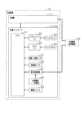
図1に示すように、空調装置10は冷暖房及び除湿機能を有する空調機11(空気調和機)と、空調機11用の無線コントローラである空調コントローラ12とを有している。空調コントローラ12では、空調機11の運転モード(冷房モード、暖房モード、除湿モード、送風モード)の切り替え、温度設定、風量や風向きの設定等の各種操作が可能であり、当該操作によって設定が変更された場合にはその旨を示す指令情報を空調機11に送信する。空調機11では受信した指令情報に基づいて運転モード等の切り替えを行う。As shown in FIG. 1, the
詳細については後述するが、空調コントローラ12は、ポータブルタイプの操作手段としてのコントローラユニット20を有している。コントローラユニット20には、空調コントローラ12における主たる制御を行うCPU51が設けられている。CPU51には、グラフィックIC52を経由してディスプレイ53が接続されている。グラフィックIC52は、CPU51からの指令情報に基づいてディスプレイ53の表示を制御する。また、CPU51には、タッチIC54を介して静電容量方式のタッチパネル55が接続されている。タッチパネル55はディスプレイ53の正面側に位置するようにして当該ディスプレイ53に積層されており、当該タッチパネル55を通じてディスプレイ53の表示内容を視認可能となるように構成されている。The
タッチIC54は、タッチパネル55が操作される場合にユーザの指が触れた部分の電流の変化(静電容量の変化)を検出する機能を有しており、その検出情報がタッチIC54からCPU51に出力される。CPU51では、入力された検出情報に基づいて操作の有無や操作の位置の判定を行う。なお、本実施形態においては、CPU51が「制御部」、タッチIC54が「検出用IC」に相当する。The
また、コントローラユニット20には、室内の温度及び湿度を検出する温度・湿度センサ57、空調コントローラ12に外力が加わった場合に発生する加速度を検出する加速度センサ58が設けられている。温度・湿度センサ57及び加速度センサ58はCPU51に接続されており、温度及び湿度の検出情報や加速度の検出情報がCPU51に集約される構成となっている。ディスプレイ53にはCPU51からの指令に基づいて室温や湿度が表示される。また、CPU51は、加速度センサ58からの検出情報に基づいてコントローラユニット20に加わった外力を把握し、その結果に基づいて上述したタッチIC54をリセットする機能を有している。このリセット機能についての詳細は後述する。The
コントローラユニット20は、電源ケーブル38(図3参照)を介して24Vの商用電源である外部電源45に接続可能となっており、外部電源45から供給される電力は空調コントローラ12に設けられた電力供給回路61を通じてCPU51、グラフィックIC52、タッチIC54等に供給される。また、コントローラユニット20には、電源スイッチ59が配設されている。電源スイッチ59はCPU51に接続されており、当該電源スイッチ59がユーザにより操作されることでコントローラユニット20をON状態/OFF状態に切替可能となっている。The
また、コントローラユニット20には、一次電池である単3電池が2つ直列に配列されてなる内部電源65(電圧=3V)が設けられている。上記外部電源45から電力供給を受けることができない状況下においては、当該内部電源65から電力供給回路61を通じてCPU51、グラフィックIC52、タッチIC54等に電力が供給される。The
ここで、図2及び図3を参照して、空調コントローラ12について補足説明する。図2に示すように、空調コントローラ12は、上記CPU51、グラフィックIC52、ディスプレイ53、タッチIC54、タッチパネル55等の各種構成が搭載された上記コントローラユニット20と、当該コントローラユニット20を保持可能なホルダ30とを有してなる。Here, the
図3に示すように、ホルダ30は、居室の壁面等への取付部として機能する平板状のベース部31と、当該ベース部31から起立する略環状の起立部32とを有し、全体として取付対象側(壁面側)とは反対側に開放された略箱状をなしている。起立部32はベース部31の縁部に沿って形成されており、当該起立部32によって空調コントローラ12の着脱方向が規定されている。コントローラユニット20が当該起立部32に沿ってホルダ30に装着される場合には、コントローラユニット20がベース部31に当接することでそれ以上の押し込みが規制される。本実施形態では、コントローラユニット20がベース部31に当接する位置が「所定位置」に相当する。As shown in FIG. 3, the
コントローラユニット20は、コントローラ本体21と、当該コントローラ本体21を操作面(表示画面)を露出させるようにして収容するケース体22とで構成されている。図3に示すように、ホルダ30の起立部32には、コントローラユニット20側に凸となる係止爪部33が形成されている。コントローラユニット20が所定位置に配置されることで係止爪部33がケース体22に形成された係止受け部23に引っ掛かり、ホルダ30からのコントローラユニット20の脱落が回避される。係止爪部33は片持ちとなっており、当該係止爪部33を指で摘まむ等して当該係止爪部33を撓ませることで係止状態が解除され、コントローラユニット20をホルダ30から取外可能となる。The
ホルダ30のベース部31にはホルダ側コネクタ35が固定されている。ホルダ側コネクタ35は電源ケーブル38を介して壁面のコンセント(外部電源45)に接続されている。コントローラユニット20の背面部には、ホルダ側コネクタ35と接続可能なユニット側コネクタ25が設けられている。これらホルダ側コネクタ35及びユニット側コネクタ25は、コントローラユニット20をホルダ30へ取り付ける(所定位置へ配置する)ことで接続される。ユニット側コネクタ25とホルダ側コネクタ35とが接続されることにより、外部電源45からコントローラユニット20の電力供給回路61(図1参照)に、電源ケーブル38→ホルダ側コネクタ35→ユニット側コネクタ25を通じて電力が供給されることとなる。A holder-
また、コントローラユニット20をホルダ30から取り外す(所定位置から移動させる)ことで分離される。ユニット側コネクタ25とホルダ側コネクタ35とが分離されることにより、外部電源45からコントローラユニット20の電力供給回路61(図1参照)への電力供給が停止され、電力供給源が内部電源65に切り替わる。The
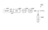
ここで、図4を参照して、電力供給経路の切り替えに係る構成について説明する。コントローラユニット20に設けられた電力供給回路61は、外部電源45からコントローラユニット20に供給された電力をCPU51等に供給する第1供給経路R1と、内部電源65からCPU51等に電力を供給する第2供給経路R2とに大別される。Now, referring to FIG. 4, the configuration related to switching of the power supply path will be described. The
第1供給経路R1には、外部電源45からコントローラユニット20に供給された電力を交流電力から直流電力に変換する変換部62(RECTIFY・SMOOTHING CIRCUIT)と、変換部62によって変換された直流電力の安定供給を実現するための安定供給部63(POWER SUPPLY)と、安定供給部63からの電力の電圧を所定電圧となるように低下させるレギュレータ64(LOW DROP OUT)とが設けられており、レギュレータ64にて電圧が引き下げられた電力がCPU51等に供給されるように構成されている。The first supply path R1 is provided with a conversion unit 62 (RECTIFY/SMOOTHING CIRCUIT) that converts the power supplied from the
なお、本実施形態に示す所定電圧は3Vとなるように規定されており、内部電源65の電圧についても3Vとなるように規定されている。つまり、内部電源65の電圧とレギュレータ64による引き下げ後の電圧とが一致するように構成されている。In this embodiment, the specified voltage is set to 3 V, and the voltage of the
第2供給経路R2の途中位置には、ソースが内部電源65に接続され、ドレインがCPU51等への出力部に接続されるようにしてP型のMOSFET67が配設されている。MOSFET67のゲートには、レギュレータ64の下流側から分岐した経路が接続されており、外部電源45から電力が供給されている場合には、レギュレータ64にて引き下げられた電圧がゲートに印加されるように構成されている。本実施形態では、このMOSFET67が「第1スイッチ」に相当する。A P-
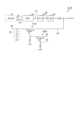
次に、図6を参照して、電力供給経路の切り替えについて説明する。図6(a)は外部電源45からコントローラユニット20に電力が供給されている状態(コントローラユニット20がホルダ30に取り付けられている状態)を示す概略図、図6(b)は外部電源45からコントローラユニット20に電力が供給されていない状態(コントローラユニット20がホルダ30から取り外されている状態)を示す概略図である。Next, switching of the power supply path will be described with reference to Fig. 6. Fig. 6(a) is a schematic diagram showing a state in which power is supplied from the
先ず、コントローラユニット20をホルダ30から取り外す際の電力供給経路の切り替えについて説明する。コントローラユニット20をホルダ30から取り外した場合には、図5(a)→図5(b)に示すように、外部電源45からコントローラユニット20への電力供給が遮断される。この場合には、第1供給経路R1を通じた電力供給が停止されるとともにMOSFET67のゲートに印加される電圧が0Vとなる。外部電源45からの電力供給の有無に関係なくMOSFET67のソースに内部電源65から3Vの電圧が印加されている点に鑑みれば、ソースの電圧を基準としてゲートに府の電圧が印加されるとも言える。First, the switching of the power supply path when the
MOSFET67のソースには内部電源65から3Vの電圧が印加されており、ソースの電圧(3V)<ゲートの電圧(0V)となってソースの電圧とゲートの電圧との差が基準電圧(閾値、例えば2V)を上回る。これにより、ソース~ドレイン間の電流の流れが許容され(MOSFET67が許容状態となり)、内部電源65からCPU51等へ電力が供給されることとなる。A voltage of 3V is applied to the source of
これに対して、コントローラユニット20をホルダ30に取り付けた場合には、図5(b)→図5(a)に示すように、外部電源45からコントローラユニット20への電力供給が開始される。この場合には、第1供給経路R1を通じてCPU51等へ電力が供給されることとなる。In contrast, when the
この場合、MOSFET67のゲートには、レギュレータ64を通じて所定電圧(3V)が印加される。ゲートの電圧が所定電圧(3V)となることで、ゲートの電圧とソースの電圧とが一致する。つまり、ソースの電圧とゲートの電圧との差が基準電圧(閾値)以下となる。これにより、ソース・ドレイン間の電流の流れが規制され(MOSFET67が規制状態となり)、内部電源65からCPU51等へ電力が供給が回避されることとなる。In this case, a predetermined voltage (3V) is applied to the gate of
以上詳述した第1の実施形態によれば、以下の優れた効果を奏する。The first embodiment described above provides the following excellent effects:
コントローラユニット20をポータブルタイプとすることにより、空調機11の設定変更等の操作を行う際の利便性を好適に向上させることができる。ここで、室内環境を快適なものとする上では空調機11を速やかに作動させることが好ましい。しかしながら、コントローラユニット20を単にポータブルタイプとして内部電源65(電池)に頼る構成とした場合には、例えば空調機11を直ちに使用したい状況であるにも関わらず内部電源65の消耗により電力が不足することで速やかな使用が困難になり得る。これは、利便性の向上を図る上で妨げになると懸念される。この点、上記第1の実施形態に示した構成によればコントローラユニット20をホルダ30の所定位置に配置している場合(すなわちホルダ30によって保持されている場合)には、外部電源45からCPU51等に電力が供給され、コントローラユニット20がホルダ30から取り外された場合には内部電源65からCPU51等に電力が供給される。このようにして、内部電源65の電力消費を抑える構成とすれば、コントローラユニット20をホルダ30から取り外して使用する際に電力不足になる機会を減らすことができる。また、仮に電力不足によって操作できない場合にはコントローラユニット20をホルダ30に取り付けることで内部電源65を交換しなくても速やかに操作可能となる。これにより、コントローラユニット20をポータブルタイプとしたことによる利便性の向上効果を好適に発揮させることができる。なお、コントローラユニット20をホルダ30に取り付けている場合には、外部電源45が優先されて内部電源65の消費が抑えられることとなる。これは、内部電源65の交換頻度の低減を図る上で好ましい。By making the controller unit 20 a portable type, it is possible to suitably improve the convenience when performing operations such as changing the settings of the
内部電源65とCPU51等への出力部との間に設けられたMOSFET67を外部電源45からの電力の供給の有無によって許容状態/規制状態に切り替える構成とすることにより、電力供給経路を外部電源側/内部電源側に簡易に切り替えることができる。The
P型のMOSFET67をスイッチとして用いる場合には、外部電源45とゲートとの間にレギュレータ64を配設し、当該レギュレータ64による電圧降下によって電圧差を閾値よりも小さくなるように抑えるとよい。これにより、上記切替機能を好適に発揮させることができる。When using a P-
例えば図5に示すように、第2供給経路において内部電源65XとCPU51等への出力部との間にダイオードを配置する構成とすれば、簡易な構成によって電力供給経路の切り替えが可能となるが、このような構成では、ダイオードにおける順方向電圧(VF)よる電圧降下によってCPU51等に供給する電力の電圧が不足し得る。特に、VFの温度特性を考慮した場合には、そのような懸念は大きくなる。例えば、内部電源65Xの電池の数を増やす等して内部電源65Xの電圧を嵩上げすることで電圧降下の影響を解消できるものの、必要な電池の数が多くなることはコントローラの重量増の要因となり上述した利便性の向上効果を発揮させる上で妨げになると懸念される。さらには、漏れ電流によって電池の許容充電電流値を超える可能性が生じ、空調コントローラの信頼性の向上を図る上で好ましくない。このように、本実施形態に示したように、MOSFET67によって供給経路を切り替える構成とすることには明確な技術的意義がある。For example, as shown in FIG. 5, if a diode is arranged between the
<第2の実施形態>
本実施形態では、電力供給回路61に係る構成が第1の実施形態と相違している。以下、図7を参照して、第1の実施形態との相違点を中心に本実施形態における電力供給回路61Bについて説明する。 Second Embodiment
In this embodiment, the configuration related to the
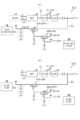
本実施形態における電力供給回路61については、内部電源65と上記出力部との間にP型のMOSFET(以下、MOSFET67Bという)が配設されている点で上記第1の実施形態に示した電力供給回路61と同様であるものの、MOSFET67Bのゲートはプルダウン抵抗を介して接地されている。このプルダウン抵抗とゲートとの間には、当該MOSFET67Bを許容状態/規制状態に切り替えるためのスイッチとしてN型のMOSFET68Bが接続されている。The
具体的には、MOSFET68Bのソースが上記プルダウン抵抗とMOSFET67Bのゲートとの間の経路部に接続されており、MOSFET68Bのドレインは内部電源65に接続されている。つまり、MOSFET68Bのドレインには、外部電源45からコントローラユニット20への電力供給の有無に関係なく、内部電源65から電圧(3V)が印加される構成となっている。Specifically, the source of
MOSFET68Bのゲートには、レギュレータ64の上流側から分岐した経路が接続されており、外部電源45から電力が供給されている場合には、レギュレータ64にる引き下げ前の電圧(例えば24V)が当該ゲートに印加されるように構成されている。なお、本実施形態では、P型のMOSFET67Bが「第1スイッチ」、N型のMOSFET68Bが「第2スイッチ」に相当する。The gate of
次に、図8を参照して、電力供給経路の切り替えについて説明する。図8(a)は外部電源45からコントローラユニット20に電力が供給されている状態(コントローラユニット20がホルダ30に取り付けられている状態)を示す概略図、図8(b)は外部電源45からコントローラユニット20に電力が供給されていない状態(コントローラユニット20がホルダ30から取り外されている状態)を示す概略図である。Next, switching of the power supply path will be described with reference to Fig. 8. Fig. 8(a) is a schematic diagram showing a state in which power is supplied from the
先ず、コントローラユニット20をホルダ30から取り外す際の電力供給経路の切り替えについて説明する。コントローラユニット20をホルダ30から取り外した場合には、図8(a)→図8(b)に示すように、外部電源45からコントローラユニット20への電力供給が遮断される。この場合には、第1供給経路R1を通じた電力供給が停止されるとともにMOSFET68Bのゲートに印加される電圧が0Vとなる。この時点では、ソースの電圧は0Vとなっており、MOSFET68Bのソースの電圧とMOSFET68Bのゲートの電圧とが一致する。つまり、ソースの電圧とゲートの電圧との差が基準電圧(閾値)以下となる。これにより、ソース・ドレイン間の電流の流れが規制され(MOSFET68Bが規制状態となり)、内部電源65からMOSFET67Bのゲートへの電圧(3V)の印加が回避されることとなる。First, the switching of the power supply path when the
MOSFET67Bのソースには内部電源65から3Vの電圧が印加されており、MOSFET67Bのゲートの電圧が0Vとなることで、MOSFET67Bのソースの電圧(3V)<MOSFET67Bのゲートの電圧(0V)となってソースの電圧とゲートの電圧との差が基準電圧(閾値、例えば2V)を上回る。これにより、ソース~ドレイン間の電流の流れが許容され(MOSFET67が許容状態となり)、内部電源65からCPU51等へ電力が供給されることとなる。A voltage of 3V is applied to the source of
これに対して、コントローラユニット20をホルダ30に取り付けた場合には、図8(b)→図8(a)に示すように、外部電源45からコントローラユニット20への電力供給が開始される。この場合には、第1供給経路R1を通じてCPU51等へ電力が供給されるとともにMOSFET68Bのゲートに印加される電圧が24Vとなる。この時点では、ソースの電圧は0Vとなっており、MOSFET68Bのソースの電圧(0V)<とMOSFET68Bのゲートの電圧(24V)となり、ソースの電圧とゲートの電圧との差が基準電圧(閾値)を上回る。これにより、ソース・ドレイン間の電流の流れが許容され(MOSFET68Bが許容状態となり)、内部電源65からMOSFET67Bのドレイン→ソースを通じてMOSFET68Bのゲートへの電圧(3V)の印加されることとなる。なお、この電圧の印加後もMOSFET68Bのソースの電圧(3V)<とMOSFET68Bのゲートの電圧(24V)の関係が維持され、ソースの電圧とゲートの電圧との差が基準電圧(閾値)を上回ったままとなる。On the other hand, when the
MOSFET67Bのソースには内部電源65から3Vの電圧が印加されており、MOSFET67Bのゲートの電圧が3Vとなることで、MOSFET67Bのソースの電圧(3V)とMOSFET67Bのゲートの電圧(3V)とが一致し、ソースの電圧とゲートの電圧との差が基準電圧(閾値、例えば2V)以下となる。これにより、ソース~ドレイン間の電流の流れが規制され(MOSFET67が規制状態となり)、内部電源65からCPU51等への電力の供給が回避されることとなる。A voltage of 3V is applied to the source of
内部電源65が電池である場合には、温度や残りの電力量によって電圧が低下し得る。ここで、本実施形態に示したように、P型のMOSFET67Bのソースとゲートとが何れも内部電源65から電圧が印加される構成とすれば、上記温度等の影響によってソースとゲートとの電圧差が左右されることを抑制できる。つまり、外部電源45からの電力供給の有無によってN型のMOSFET68Bを制御し、当該MOSFET68Bを通じてP型のMOSFET67Bのゲートに印加される電圧(内部電源からの電圧)を制御する構成とすれば、上記温度等の影響を極力小さく抑えることができる。電力供給経路の切替機能の信頼性を向上させる上で好ましい。If the
P型のMOSFET67BのゲートにN型のMOSFET68Bのソースを接続し、外部電源45の電圧によってN型のMOSFET68Bを許容状態/規制状態に切り替える構成とすることにより、上記切替機能を好適に発揮させることができる。特に、N型のMOSFET68Bのゲートには、ソースの電圧に対して十分に大きな電圧を印加することができるため、電力経路の切替機能に対する信頼性を好適に向上させることができる。The above switching function can be suitably exercised by connecting the source of N-
<第3の実施形態>
上記各実施形態に示したように、コントローラユニット20に静電容量方式のタッチパネル55を用いた場合には、コントローラユニット20の大型化を抑制しつつ空調設定に係る情報の表示領域(表示画面)を極力大きくすることができる。これは、表示画面に表示される各種情報の視認性を向上させて、ユーザの満足度を高める上で好ましい。但し、この種のコントローラにおいては、ユーザの指から伝わる静電気等に起因してタッチIC54に異常が発生するといった新たな課題が生じる。この種の異常については、例えば空調コントローラの電源をON/OFFする等して当該空調コントローラ12を再起動させることで解消できる場合がある。しかしながら、このような再起動用の操作が必要となったり再起動が完了するまでの待ち時間が長くなったりすることは、速やかな温度等の設定変更の妨げになると懸念される。特に、空調コントローラが多機能化/高機能化されることで再起動に係る待ち時間が長くなり、上記懸念が顕在化すると想定される。本実施形態では、空調コントローラの利便性を好適に向上させるべく、上述した事情に配慮した工夫がなされていることを特徴の1つとしている。以下、図9を参照して、空調コントローラ12の基本構成について補足説明し、その後、上記工夫について説明する。なお、第1の実施形態等と共通の構成については説明を省略する。 Third Embodiment
As shown in each of the above embodiments, when the capacitive touch panel 55 is used in the
図9(a)は、コントローラユニット20の表示画面81にメインメニューが表示されている場合を例示している。メインメニューでは、現在の運転モード、室内温度、設定温度等の各種情報と、運転切替用の操作アイコン82、ファン切替用の操作アイコン83、温度設定用の操作アイコン84等の各種操作アイコンとが表示される。メインメニューにおいて運転切替用の操作アイコン82が指で押された場合(操作された場合)には表示画面81の表示がメインメニューから運転切替メニューに切り替わり、ファン切替用の操作アイコン83が指で押された場合(操作された場合)には表示画面81の表示がメインメニューからファン切替メニューに切り替わり、温度設定用の操作アイコン84が指で押された場合(操作された場合)には表示画面81の表示がメインメニューから温度設定メニューに切り替わる。9(a) illustrates an example in which the main menu is displayed on the
図9(b)に例示しているように、温度設定メニューを開いている場合には、表示画面81に、現在の設定温度と、設定温度を上げるための操作アイコンである上矢印のUPアイコン87と、設定温度を下げるための操作アイコンである下矢印のDOWNアイコン88とが表示される。図10に示すように、温度設定用の操作アイコンが操作され、CPU51にて当該操作を受け付けた場合には、空調機11に設定変更用の指令情報を送信するとともに表示画面81に表示中の設定温度を変更する。As shown in FIG. 9(b), when the temperature setting menu is open, the
ユーザが温度設定用の操作アイコンに触れた際にユーザの指先からコントローラユニット20(詳しくはタッチパネル55)に静電気が流れ、この静電気がタッチICに伝わった場合にはタッチICに動作異常が発生し得る。具体的には、タッチICがフリーズし、フリーズ中にタッチパネル55に触れたとしても静電容量の変化を検出できなくなるといった異常が発生し得る。本実施形態に示すCPU51では、タッチIC用の挙動を監視しているわけではないため、タッチICからの情報に基づいて操作判定を正常に行うことができなくなる。この結果、上記UPアイコン87やDOWNアイコン88が操作されたとしても、表示画面81に表示中の設定温度は変更されず、空調機11が把握している設定温度についても変更されないままとなる。When the user touches the operation icon for setting the temperature, static electricity flows from the user's fingertip to the controller unit 20 (more specifically, the touch panel 55). If this static electricity is transmitted to the touch IC, an operational abnormality may occur in the touch IC. Specifically, the touch IC may freeze, causing an abnormality in which it is unable to detect a change in capacitance even if the touch panel 55 is touched while frozen. The
ここで、CPU51は、操作検出用のタッチICとは別に設けられた検出手段である上記加速度センサ58からの検出情報に基づいてタッチIC54を単体でリセットさせる機能を有している。具体的には、CPU51において所定の周期(例えば1msec毎)に実行される定期処理にICリセット用処理が組み込まれている。以下、図11のフローチャートを参照して、当該ICリセット用処理について説明する。Here, the
ICリセット用処理においては先ず、ステップS101にてコントローラユニット20のRAMにリセット中フラグが格納されているか否かを判定する。リセット中フラグが格納されていない場合には、ステップS101にて否定判定をしてステップS102に進む。ステップS102では、加速度センサ58からの検出情報に基づいてコントローラユニット20に振動が発生したか否か、具体的には予め規定されている閾値を超えた加速度の変化が発生したか否かを判定する。振動が発生していない場合又は発生しているとしても加速度が閾値以下である場合にはステップS102にて否定判定をして、そのまま本ICリセット用処理を終了する。閾値を超える振動が発生している場合には、ステップS102にて肯定判定をしてステップS104に進む。In the IC reset process, first, in step S101, it is determined whether or not a resetting flag is stored in the RAM of the
ステップS104では、振動発生周期の算出処理を実行する。振動発生周期の算出処理では今回の振動及びその直前のN回(例えばN=2以上)の振動の計N+1回分の振動から振動の発生周期、すなわち振動発生のインターバル期間の平均を算出する。この発生周期が基準期間よりも短い場合にはステップS104にて肯定判定をしてステップS105に進む。In step S104, a calculation process for the vibration occurrence period is executed. In the calculation process for the vibration occurrence period, the vibration occurrence period, i.e., the average interval period between vibration occurrences, is calculated from a total of N+1 vibrations, including the current vibration and the immediately preceding N vibrations (e.g., N=2 or more). If this occurrence period is shorter than the reference period, a positive judgment is made in step S104 and the process proceeds to step S105.
ステップS105では、上記周期を算出するためのタイマカウンタ等のICリセット用の各種カウンタをリセットする。続くステップS106ではタッチIC54のリセット処理(初期化処理)を実行する。これにより、上記フリーズが解消され、タッチIC54の検出機能が復活する。その後は、ステップS107にてRAMにリセット中フラグをセットして、本ICリセット用処理を終了する。なお、本実施形態においては、タッチIC54のリセットに要する所要期間については1sec程度となっており、上記電源スイッチ59の操作によってCPU51を再起動させる場合の所要期間(例えば5sec)よりも短くなっている。In step S105, various counters for IC reset, such as a timer counter for calculating the cycle, are reset. In the following step S106, a reset process (initialization process) of the
ステップS104の説明に戻り、当該ステップS104にて否定判定をした場合、すなわち算出した振動の発生周期が基準期間に達していない場合には、ステップS108に進む。ステップS108では、今回の振動の大きさ(詳しくは検出した加速度)が基準値を上回っているか否かを判定する。なお、ステップS108に示す基準値は、振動発生の有無を判定する際に参照される閾値よりも大きい値である。Returning to the explanation of step S104, if a negative determination is made in step S104, i.e., if the calculated vibration occurrence period has not reached the reference period, the process proceeds to step S108. In step S108, it is determined whether or not the magnitude of the current vibration (more specifically, the detected acceleration) exceeds a reference value. Note that the reference value shown in step S108 is a value greater than the threshold value that is referenced when determining whether or not vibration has occurred.
今回の加速度が基準値を超えていない場合には、ステップS108にて否定判定をして、そのまま本ICリセット用処理を終了する。ステップS108にて肯定判定をした場合には、ステップS109に進む。ステップS109では、基準値を超える加速度の振動が連続して発生(2回発生)したか否かを判定する。連続発生していない場合には、ステップS109にて否定判定をして本ICリセット用処理を終了する。連続発生している場合には、上記ステップS105~S107の各処理を実行した後、本ICリセット用処理を終了する。If the current acceleration does not exceed the reference value, a negative judgment is made in step S108, and the IC reset process is terminated. If a positive judgment is made in step S108, the process proceeds to step S109. In step S109, it is determined whether vibrations with acceleration exceeding the reference value have occurred consecutively (occurred twice). If they have not occurred consecutively, a negative judgment is made in step S109, and the IC reset process is terminated. If they have occurred consecutively, the processes in steps S105 to S107 are executed, and then the IC reset process is terminated.
ステップS101の説明に戻り、当該ステップS101にて肯定判定をした場合、すなわちRAMにリセット中フラグが格納されている場合には、ステップS110に進む。ステップS110ではタッチIC54のリセットが完了したか否かを判定する。具体的には、リセット用のタイマカウンタを用いてリセット開始からの経過期間を把握しており、このリセット用のタイマカウンタの値が1sec(リセットの所要期間)に相当する値となっているかを判定する。ステップS110にて否定判定をした場合には、そのまま本ICリセット用処理を終了する。ステップS110にて肯定判定をした場合にはステップS111に進み、RAMに格納されているリセット用フラグを消去した後、本ICリセット用処理を終了する。Returning to the explanation of step S101, if a positive determination is made in step S101, i.e., if a resetting in progress flag is stored in the RAM, the process proceeds to step S110. In step S110, it is determined whether or not the resetting of the
ここで、タッチIC54のリセット中は、表示画面81における表示がリセット前後で同一となるように維持される。リセットの都度、その旨を報知する構成としないことにより、当該リセット機能がユーザに煩わしいとの印象を与えることを抑制している。Here, while the
ここで、図12及び図13を参照して、タッチIC54に異常が発生して操作が受け付けられなくなった場合の遊技者の操作態様の変化について説明する。図12に示す例では、タッチIC54が正常な状態に維持されている。この場合、ta1のタイミングで温度設定用の操作アイコン(DOWNアイコン88)が操作される(押される)度に、表示画面81に表示されている設定温度が変更されている(「24」→「23」→「22」)。ユーザは表示されている設定温度を目視で確認しながら操作を行うため、各操作のインターバル期間はある程度長くなると想定される。Now, referring to Figures 12 and 13, we will explain the change in the player's operating behavior when an abnormality occurs in the
図13(a)に示す例においても、tb1のタイミングで温度設定用の操作アイコン(DOWNアイコン88)が操作される(押される)ことにより、表示画面81に表示中の設定温度が「24」→「23」に変更されている。しかしながら、このタイミングでユーザの指からタッチIC54に静電気が伝わることで当該タッチIC54に異常が発生している。このため、続くtb2のタイミング及びtb3のタイミングで温度設定用の操作アイコン(DOWNアイコン88)が操作され(押され)たとしても、表示画面81に表示中の設定温度が「24」のままとなる。温度が変更されないことに気づいたユーザが操作アイコンを連打するようにして操作態様(操作条件)を変更することで、tb3のタイミング、tb4のタイミング及びtb5のタイミングで上記振動がたて続けに発生している。tb5のタイミングで振動発生周期を算出した場合、当該周期は上記基準期間よりも短くなっている。故に、tb5のタイミングの振動(タッチパネル55の操作、操作アイコンの押し操作)を契機としてタッチIC54がリセットされることとなる。つまり、上記ICリセット用処理におけるステップS103~S104の処理は、このような連打操作を契機としてタッチIC54をリセットするための処理である。13A, the temperature setting operation icon (DOWN icon 88) is operated (pressed) at the timing of tb1, and the set temperature displayed on the
図13(b)に示す例においても、tc1のタイミングで温度設定用の操作アイコン(DOWNアイコン88)が操作される(押される)ことにより、表示画面81に表示中の設定温度が「24」→「23」に変更されている。しかしながら、このタイミングでユーザの指からタッチIC54に静電気が伝わることで当該タッチIC54に異常が発生している。このため、続くtc2のタイミング及びtc3のタイミングで温度設定用の操作アイコン(DOWNアイコン88)が操作され(押され)たとしても、表示画面81に表示中の設定温度が「24」のままとなる。温度が変更されないことに気づいたユーザが操作アイコンを強打するようにして操作態様(操作条件)を変更することで、tc4のタイミング及びtc5のタイミングで上記基準値を超える振動が連続して発生している。故に、tc5のタイミングの振動(タッチパネル55の操作、操作アイコンの押し操作)を契機としてタッチIC54がリセットされることとなる。つまり、上記ICリセット用処理におけるステップS108~S109の処理は、このような強打を契機としてタッチIC54をリセットするための処理である。13B, the temperature setting operation icon (DOWN icon 88) is operated (pressed) at the timing of tc1, and the set temperature displayed on the
上述したように、タッチパネル55の操作アイコンを押したにも関わらず操作が正常に受け付けられない場合の原因は、上記タッチIC側ではなくCPU51側に存在する可能性もある。そこで、CPU51は、タッチIC54のリセットがたて続けに発生した場合には、当該CPU51をリセット(再起動)させる処理(CPU用リセット処理)を実行する。CPUリセット用処理は、CPU51にて定期処理の一環として実行される再起動用の処理である。As described above, when an operation icon on the touch panel 55 is pressed but the operation is not normally accepted, the cause may lie not in the touch IC but in the
図14に示すように、CPUリセット用処理においては先ず、ステップS201にてICリセットが発生したか否かを判定する。ステップS201にて否定判定をした場合にはそのまま本CPUリセット用処理を終了する。ステップS201にて肯定判定をした場合には、ステップS202に進む。ステップS202では、予め設定された基準期間(例えば5sec)内のタッチIC54のリセット回数が基準回数(例えば3回)に達したか否かを判定する。ステップS202にて否定判定をした場合には、そのまま本CPUリセット処理を終了する。ステップS202にて肯定判定をした場合には、ステップS203にてタッチIC54のリセット回数を特定するための回数カウンタや、上記基準期間の経過を特定するためのタイマカウンタ等のCPUリセット用の各種カウンタをリセットする。その後は、ステップS204にてCPUリセット処理を実行し、本CPUリセット用処理を終了する。CPU51のリセット中は、グラフィックIC52によりディスプレイ53が駆動制御され表示画面81にCPU51をリセット中であること示す情報(例えば「Please Wait」の文字)が表示(報知)される(図15参照)。As shown in FIG. 14, in the CPU reset process, first, in step S201, it is determined whether or not an IC reset has occurred. If a negative determination is made in step S201, the CPU reset process is terminated. If a positive determination is made in step S201, the process proceeds to step S202. In step S202, it is determined whether or not the number of resets of the
以上詳述した第3の実施形態によれば、以下の優れた効果を奏する。The third embodiment described above provides the following excellent effects:
上述したコントローラユニット20によれば、ユーザの操作に基づいて所定のリセット条件(連打発生や強打発生)が成立した場合に、コントローラユニット20を作動状態に維持したままタッチIC54がリセットされる。つまり、タッチIC54に異常が発生した後の操作(例えば空調設定操作)を契機として、所定のリセット条件→タッチIC54のリセットとなる構成とすることにより、リセット時の待ち時間を極力短くすることができる。これにより、ユーザの利便性の向上に寄与できる。According to the
なお、CPU51はタッチIC54からの検出情報に基づいて操作判定を行う構成であり、仮に上述した動作異常が発生したとしても、それをCPU51側にて把握することは困難になる。故に、タッチIC54に異常が発生しているか否かに関係なく、CPU51においてユーザの操作に基づいて所定のリセット条件が成立し得る構成とすることにより、タッチIC54の挙動の監視が不要となり、上述した利便性の向上効果を発揮させる上で空調コントローラ12に係る構成が過度に複雑になることを抑制できる。The
タッチIC54に異常が発生して操作が正常に受け付けられなくなった場合に、同じ箇所(操作アイコン等)を強く叩いたり、短い周期で連続して操作したりすると想定される。このような操作態様に配慮してリセットの基準となる操作態様(所定態様)を定め、当該所定態様にて操作が行われた場合にタッチIC54をリセットすることで、上記異常を速やかに解消できる。なお、静電容量方式のコントローラユニット20に加速度センサ58を配設し、当該加速度センサ58により検出された情報からタッチパネル55の操作態様を特定する構成とすれば、上述した各種効果を好適に発揮させることができる。When an abnormality occurs in the
仮にタッチIC54をリセットする都度、表示画面81の表示を変更する構成とした場合には、当該変更が多発することでユーザに煩わしいとの印象を与える可能性がある。また、操作アイコン等が非表示になる等して見づらくなることは、リセット後の操作の際に操作アイコン等の再確認が必要になり、ユーザの利便性が低下すると懸念される。この点、上述の如く表示画面81の表示がリセットの前後で同様となるようにして表示が維持される構成とすることで、上記懸念を好適に払拭できる。If the display on the
実施頻度が相対的に低いCPU51のリセットについてはリセット発生を報知する一方、実施頻度が相対的に高いタッチIC54のリセットについてはリセット発生を報知しない構成とすることで、ユーザを煩わせることなく空調コントローラ12の機能を回復させることができる。By configuring the system to notify the occurrence of a reset of the
<その他の実施形態>
なお、上述した各実施形態の記載内容に限定されず例えば次のように実施してもよい。ちなみに、以下の各構成を個別に上記各実施形態に対して適用してもよく、一部又は全部を組み合わせて上記各実施形態に対して適用してもよい。また、上記各実施形態に示した各種構成の全て又は一部を任意に組み合わせることも可能である。この場合、組み合わせの対象となる各構成の技術的意義(発揮される効果)が担保されることが好ましい。 <Other embodiments>
The present invention is not limited to the contents of the above-described embodiments, and may be implemented, for example, as follows. Each of the following configurations may be applied individually to each of the above-described embodiments, or may be applied to each of the above-described embodiments in combination in part or in whole. It is also possible to arbitrarily combine all or part of the various configurations shown in each of the above-described embodiments. In this case, it is preferable that the technical significance (effects to be exerted) of each of the configurations to be combined is guaranteed.
・上記各実施形態では、MOSFETを用いて電力供給経路を切り替える構成としたが、バイポーラトランジスタ等の他のスイッチング素子を用いて電力供給経路を切り替える構成としてもよい。- In each of the above embodiments, the power supply path is switched using a MOSFET, but the power supply path may be switched using other switching elements such as a bipolar transistor.
・上記各実施形態に示したコントローラユニット20にタッチIC54をリセットするためのリセットボタン等の操作部を設けてもよい。- The
・上記各実施形態に示した空調コントローラ12は、コントローラユニット20をホルダ30に取り付けることでホルダ側コネクタ35とユニット側コネクタ25とが接続され、コントローラユニット20をホルダ30から取り外すことでホルダ側コネクタ35とユニット側コネクタ25とが分離される構成とした。すなわち、電源ケーブル38とコントローラユニット20とが当該コントローラユニット20の着脱作業によって自動的に接続/分離される構成とした。これを変更し、例えばコントローラユニット20をホルダ30に取り付た状態で上述した電源ケーブル38を手作業でコントローラユニット20に直接着脱する構成を否定するものではない。The
・上記各実施形態では、空調コントローラ12をポータブル式としたが、固定式とすることも可能である。また、タッチパネル55については静電容量方式以外の方式(例えば、抵抗膜方式、光学方式、超音波表面弾性波方式等)とすることも可能である。- In each of the above embodiments, the
・上記各実施形態では、「内部電源」として一次電池を用いる構成としたが、「内部電源」として二次電池を用いる構成と否定するものではない。- In each of the above embodiments, a primary battery is used as the "internal power source," but this does not mean that a secondary battery can be used as the "internal power source."
・上記第2の実施形態では、N型のMOSFET68Bのゲートに外部電源45から24Vの電圧が印加される構成としたが、これに限定されるものではない、MOSFET68Bを許容状態/規制状態に切り替えることで電力供給経路を切り替えることができるのであれば足り、MOSFET68Bのゲートに印加される電圧を24Vよりも小さくすることも可能である。- In the second embodiment described above, a voltage of 24 V is applied to the gate of N-
・タッチIC54のリセット完了から第1の期間を経過するまでの間に操作アイコンが操作された場合には、次の操作判定を当該操作から第2の期間が経過するまで無効とする構成としてもよい。上述したようにタッチIC54に異常が発生して操作が正常に受け付けられなくなった場合には、操作アイコン等が連打される可能性がある。このような操作が行われている最中にリセットが完了すると、操作を繰り返し受け付けてしまうことでユーザの意図から外れて空調設定が変更され得る。例えば、温度変更用の操作アイコンが連打された場合には、リセット完了後に設定温度が大きく変更され得る。この点、本変形例に示すように、タッチIC54をリセットした後の第1の期間内にCPU51にて操作が行われたと判定した場合には、当該CPU51による次の操作判定を第2の期間が経過するまで一時的に無効化する構成とすることで、上記不都合の発生を好適に抑制できる。- If an operation icon is operated between the completion of resetting the
・ユーザの過去の操作実績を記憶し、当該記憶されている操作実績に基づいて上記第3の実施形態に示した基準周期、基準値等の各種閾値(所定のリセット条件)を補正する構成としてもよい。ユーザによってはタッチパネル55が操作される場合の強度や周期等が様々となり得るため、過去の操作実績に基づいて所定のリセット条件を補正することにより、タッチIC54をリセットする必要がない状況下において当該リセットが発生する機会を減らすことができる。- A configuration may be adopted in which the user's past operation records are stored, and various thresholds (predetermined reset conditions) such as the reference period and reference value shown in the third embodiment described above are corrected based on the stored operation records. Since the strength and period when the touch panel 55 is operated may vary depending on the user, correcting the predetermined reset conditions based on the past operation records can reduce the opportunities for resetting the
・上記第3の実施形態に示したように、タッチIC54の異常によって操作が正常に受け付けられなくなった場合には、ユーザは操作態様(操作条件)を変更して操作を続けると想定される。この操作態様については、上述した連打や強打以外にも、ロングタップ(長押し)、フリック、マルチタップ等が想定される。これらの操作を、上記加速度センサ58に加えて又は代えて圧力センサにより検出し、これらの操作が行われた場合にタッチIC54をリセットする構成としてもよい。但し、圧力センサによって上記各種操作を検出する上では当該圧力センサの数が嵩むと想定される。故に、上述の如く加速度センサ58を用いることには、コントローラユニット20の構成の複雑化を極力抑えつつユーザの利便性を向上できるという技術的意義がある。- As shown in the third embodiment, when an operation cannot be normally accepted due to an abnormality in the
・上記第3の実施形態では、タッチパネル55が連続して強打されたことを契機としてタッチIC54をリセットする構成としたが、これに限定されるものではない。タッチパネル55が1回強打されたことを契機としてタッチIC54をリセットする構成とすることも可能である。- In the third embodiment described above, the
・加速度センサ58の配置については任意である。例えばコントローラユニット20の中央部分に配設してもよいし、コントローラユニット20の端部に配設してもよい。- The location of the
・上記第3の実施形態では、タッチIC54をリセットしている旨をユーザに報知しない構成としたが、タッチIC54をリセットしている旨をユーザに報知する構成としてもよい。- In the third embodiment described above, the user is not notified that the
10…空調装置、11…空調機、12…空調コントローラ、20…コントローラユニット、25…ユニット側コネクタ、30…ホルダ、35…ホルダ側コネクタ、45…外部電源(商用電源)、51…CPU(制御部)、54…タッチIC(検出用IC)、55…タッチパネル、58…加速度センサ、61…電力供給回路、64…LDO、65…内部電源、67…P型のMOSFET(第1スイッチ)、68…N型のMOSFET(第2スイッチ)、81…表示画面、R1…第1供給経路、R2…第2供給経路。10...air conditioner, 11...air conditioner, 12...air conditioning controller, 20...controller unit, 25...unit side connector, 30...holder, 35...holder side connector, 45...external power supply (commercial power supply), 51...CPU (controller), 54...touch IC (detection IC), 55...touch panel, 58...acceleration sensor, 61...power supply circuit, 64...LDO, 65...internal power supply, 67...P-type MOSFET (first switch), 68...N-type MOSFET (second switch), 81...display screen, R1...first supply path, R2...second supply path.
Claims (8)
Translated fromJapaneseユーザにより操作される操作部が露出させられて設けられたコントローラユニットと、
一方側が開放された形状をなし、所定位置に配置された前記コントローラユニットを、前記ユーザが前記操作部を操作可能な状態で保持するホルダと、
前記コントローラユニットが前記ホルダの前記所定位置に配置されている場合には、商用電源から当該コントローラユニットの制御部に電力が供給され、前記コントローラユニットが前記所定位置に配置されていない場合には当該コントローラユニットの内部電源から前記制御部に電力が供給されるように電力供給経路を切り替える経路切替手段と
を備え、
前記経路切替手段は、前記電力供給経路において前記内部電源と前記制御部との間となる部分に設けられ、前記内部電源から前記制御部への電力供給を許容する第1状態と、前記内部電源から前記制御部への電力供給を規制する第2状態とに切替可能なスイッチを有し、
前記スイッチは、前記商用電源から前記コントローラユニットへ電力が供給されている場合には前記第2状態となり、前記商用電源から前記コントローラユニットへ電力が供給されていない場合には前記第1状態となるように構成されており、
前記内部電源は電池であり、
前記スイッチは、P型のMOSFETである第1スイッチであり、
前記第1スイッチは、当該第1スイッチのソースに前記内部電源が接続され、当該第1スイッチのドレインに前記制御部が接続され、当該第1スイッチのゲートにN型のMOSFETである第2スイッチを介して前記内部電源が接続され、当該第1スイッチのソースの電圧と当該第1スイッチのゲートの電圧との差が第1所定値よりも小さい場合に前記第2状態となり、当該第1スイッチのソースの電圧と当該第1スイッチのゲートの電圧との差が前記第1所定値よりも大きい場合に前記第1状態となるように構成されており、
前記第2スイッチは、前記商用電源から前記コントローラユニットへ電力が供給されている場合には、前記第1スイッチの前記ゲートに前記内部電源から前記ソースの電圧の差が前記第1所定値よりも小さくなるようにして電圧を印加する第3状態となり、前記商用電源から前記コントローラユニットへ電力が供給されていない場合には、前記内部電源から前記第1スイッチのゲートに電圧が印加されず前記ゲートの電圧と前記ソースの電圧との差が前記第1所定値よりも大きい第4状態となるように構成されている空調コントローラ。 An air conditioning controller capable of controlling an air conditioner based on a user's operation,
a controller unit having an exposed operation unit that is operated by a user;
a holder having an open shape on one side and configured to hold the controller unit arranged at a predetermined position in a state in which the user can operate the operation unit;
a path switching means for switching a power supply path so that, when the controller unit is placed at the predetermined position of the holder, power is supplied from a commercial power source to a control unit of the controller unit, and, when the controller unit is not placed at the predetermined position, power is supplied from an internal power source of the controller unit to the control unit,
the path switching means is provided in a portion of the power supply path between the internal power source and the control unit, and has a switch switchable between a first state that permits power supply from the internal power source to the control unit and a second state that restricts power supply from the internal power source to the control unit;
the switch is configured to be in the second state when power is supplied from the commercial power source to the controller unit, and to be in the first state when power is not supplied from the commercial power source to the controller unit;
the internal power source is a battery;
the switch is a first switch which is a P-type MOSFET;
the first switch is configured such that the internal power supply is connected to a source of the first switch, the control unit is connected to a drain of the first switch, and the internal power supply is connected to a gate of the first switch via a second switch which is an N-type MOSFET, and the first switch is in the second state when a difference between a voltage at the source of the first switch and a voltage at the gate of the first switch is smaller than a first predetermined value, and is in the first state when a difference between a voltage at the source of the first switch and a voltage at the gate of the first switch is larger than the first predetermined value;
The air conditioning controller is configured so that, when power is supplied to the controller unit from the commercial power source, the second switch is in a third state in which a voltage is applied to the gate of the first switch such that the voltage difference from the internal power source to the source is smaller than the first predetermined value, and, when power is not supplied to the controller unit from the commercial power source, no voltage is applied to the gate of the first switch from the internal power source and the difference between the voltage of the gate and the voltage of the source is larger than the first predetermined value .
前記コントローラユニットに設けられ、前記ホルダ側接続端子に接続可能なコントローラ側接続端子と
を備え、
それらホルダ側接続端子とコントローラ側接続端子とが接続されている場合に前記商用電源から前記制御部へ電力が供給される構成となっており、
前記ホルダ側接続端子及び前記コントローラ側接続端子は、前記コントローラユニットが前記所定位置に配置されることで互いに接続され、前記コントローラユニットが前記所定位置から外れることで当該接続が解除される構成となっている請求項1乃至請求項3のいずれか1つに記載の空調コントローラ。 a holder-side connection terminal provided in the holder and receiving power from the commercial power source;
a controller-side connection terminal provided in the controller unit and connectable to the holder-side connection terminal;
When the holder-side connection terminal and the controller-side connection terminal are connected, power is supplied from the commercial power source to the control unit.
An air conditioning controller as described in any one of claims 1 to 3, wherein the holder side connection terminal and the controller side connection terminal are connected to each other when the controller unit is placed at the predetermined position, and the connection is released when the controller unit is removed from the predetermined position.
前記商用電源から前記コントローラユニットへ電力が供給されている場合には、前記第2スイッチが前記第2スイッチのゲートの電圧と前記第2スイッチのソースの電圧との差が第2所定値よりも大きい状態である前記第3状態となることにより前記第1スイッチのゲートに前記内部電源から電圧が印加されることで前記第1スイッチが前記第2状態となり、
前記商用電源から前記コントローラユニットへ電力が供給されていない場合には、前記第2スイッチの前記ゲートの電圧と前記第2スイッチの前記ソースの電圧との差が前記第2所定値よりも小さくなるようにして前記第1スイッチの前記ゲートへの前記内部電源からの電圧の印加が回避される状態である前記第4状態となることにより前記第1スイッチが前記第1状態となるように構成されている請求項1乃至請求項4のいずれか1つに記載の空調コントローラ。 the second switch is an N-type MOSFET having a gate connected to the commercial power supply, a drain connected to the internal power supply, and a source connected to the gate of the first switch when power is supplied from the commercial power supply to the controller unit;
When power is being supplied from the commercial power source to the controller unit, the second switch is in the third state in which a difference between a voltage at the gate of the second switch and a voltage at the source of the second switch is greater than a second predetermined value, and a voltage is applied from the internal power source to the gate of the first switch, thereby causing the first switch to be in the second state;
5. An air conditioning controller as described in any one of claims 1 to 4, configured such that when power is not supplied to the controller unit from the commercial power source, the first switch enters the first state by entering the fourth state in which application of voltage from the internal power source to the gate of the first switch is avoided by making the difference between the voltage of the gate of the second switchand the voltage of the source of the second switch smaller than the second predetermined value.
前記コントローラユニットが商用電源に接続されている場合には当該商用電源から前記制御部に電力が供給され、当該コントローラユニットが前記商用電源に接続されていない場合には内部電源から前記制御部に電力が供給されるように電力供給経路を切り替える経路切替手段を備え、
前記経路切替手段は、
前記電力供給経路において前記内部電源と前記制御部との間となる部分に設けられ、ソースに前記内部電源が接続され、ドレインに前記制御部が接続されたP型の第1MOSFETと、
ソースが前記第1MOSFETのゲートに接続され、ドレインが前記内部電源に接続され、前記商用電源から前記コントローラユニットへ電力が供給されている場合にゲートが前記商用電源に接続されるN型の第2MOSFETと
を有し、
前記内部電源は電池であり、
前記第1MOSFETは、前記第1MOSFETのソースの電圧と前記第1MOSFETのゲートの電圧との差が第1所定値よりも大きい場合には、前記第1MOSFETのソースから前記第1MOSFETのドレインへの電流の流れを許容する許容状態となり、前記第1MOSFETのソースの電圧と前記第1MOSFETのゲートの電圧との差が第1所定値よりも小さい場合には、前記第1MOSFETのソースから前記第1MOSFETのドレインへの電流の流れを規制する規制状態となるように構成されており、
前記第2MOSFETは、前記第2MOSFETのソースの電圧と前記第2MOSFETのゲートの電圧との差が第2所定値よりも大きい場合には、前記第2MOSFETのドレインから前記第2MOSFETのソースへの電流の流れを許容する許容状態となり、前記第2MOSFETのソースの電圧と前記第2MOSFETのゲートの電圧との差が第2所定値よりも小さい場合には、前記第2MOSFETのドレインから前記第2MOSFETのソースへの電流の流れを規制する規制状態となるように構成されており、
前記第1MOSFETは、前記商用電源から前記コントローラユニットへ電力が供給されている場合には、前記商用電源からの電圧が前記第2MOSFETのゲートに印加されて当該第2MOSFETが前記許容状態となって前記第1MOSFETのゲートに前記内部電源から電圧が印加されることにより前記規制状態となり、前記商用電源から前記コントローラユニットへ電力が供給されていない場合には、前記商用電源からの電圧が前記第2MOSFETのゲートに印加されず当該第2MOSFETが前記規制状態となって前記第1MOSFETのゲートへの前記内部電源から電圧の印加が回避されることにより前記許容状態となるように構成されている空調コントローラ。 An air conditioning controller having a controller unit provided with an operation unit operated by a user and a control unit that outputs command information to an air conditioner based on the operation of the operation unit,
a path switching means for switching a power supply path so that, when the controller unit is connected to a commercial power source, power is supplied to the control unit from the commercial power source, and, when the controller unit is not connected to the commercial power source, power is supplied to the control unit from an internal power source;
The route switching means includes:
a first MOSFET of P type provided in a portion of the power supply path between the internal power supply and the control unit, the first MOSFET having a source connected to the internal power supply and a drain connected to the control unit;
a second N-type MOSFET having a source connected to the gate of the first MOSFET, a drain connected to the internal power supply, and a gate connected to the commercial power supply when power is being supplied from the commercial power supply to the controller unit;
the internal power source is a battery;
the first MOSFET is configured to be in a permissive state in which a current flows from the source of the first MOSFET to the drain of the first MOSFET when a difference between a voltage at the source of the first MOSFET and a voltage at the gate of the first MOSFET is greater than a first predetermined value, and to be in a restricted state in which a current flow from the source of the first MOSFET to the drain of the first MOSFET is restricted when a difference between a voltage at the source of the first MOSFET and a voltage at the gate of the first MOSFET is smaller than a first predetermined value;
the second MOSFET is configured to be in an allowable state in which a current flows from the drain of the second MOSFET to the source of the second MOSFET when a difference between a voltage of the source of the second MOSFET and a voltage of the gate of the second MOSFET is larger than a second predetermined value, and to be in a restricted state in which a current flow from the drain of the second MOSFET to the source of the second MOSFET is restricted when a difference between a voltage of the source of the second MOSFET and a voltage of the gate of the second MOSFET is smaller than a second predetermined value;
The air conditioning controller is configured so that, when power is supplied to the controller unit from the commercial power supply, a voltage from the commercial power supply is applied to the gate of the second MOSFET, causing the second MOSFET to enter the permissive state, and a voltage is applied from the internal power supply to the gate of the first MOSFET, causing the first MOSFET to enter the regulated state; and, when power is not supplied to the controller unit from the commercial power supply, a voltage from the commercial power supply is not applied to the gate of the second MOSFET, causing the second MOSFET to enter the regulated state, and application of voltage from the internal power supply to the gate of the first MOSFET is avoided, causing the first MOSFET to enter the permissive state.
Priority Applications (2)
| Application Number | Priority Date | Filing Date | Title |
|---|---|---|---|
| JP2019224300AJP7534587B2 (en) | 2019-12-12 | 2019-12-12 | Air conditioning controller and air conditioning device |
| US17/115,980US11595040B2 (en) | 2019-12-12 | 2020-12-09 | Air conditioning controller for controlling an air conditioner |
Applications Claiming Priority (1)
| Application Number | Priority Date | Filing Date | Title |
|---|---|---|---|
| JP2019224300AJP7534587B2 (en) | 2019-12-12 | 2019-12-12 | Air conditioning controller and air conditioning device |
Publications (2)
| Publication Number | Publication Date |
|---|---|
| JP2021092362A JP2021092362A (en) | 2021-06-17 |
| JP7534587B2true JP7534587B2 (en) | 2024-08-15 |
Family
ID=76312096
Family Applications (1)
| Application Number | Title | Priority Date | Filing Date |
|---|---|---|---|
| JP2019224300AActiveJP7534587B2 (en) | 2019-12-12 | 2019-12-12 | Air conditioning controller and air conditioning device |
Country Status (2)
| Country | Link |
|---|---|
| US (1) | US11595040B2 (en) |
| JP (1) | JP7534587B2 (en) |
Citations (7)
| Publication number | Priority date | Publication date | Assignee | Title |
|---|---|---|---|---|
| WO2004043109A1 (en) | 2002-11-06 | 2004-05-21 | Goim Inc. | Control and automatic appartus for swiching circuit using wireless communication |
| JP2004242396A (en) | 2003-02-04 | 2004-08-26 | Matsushita Electric Ind Co Ltd | Power supply for backup |
| JP2006153337A (en) | 2004-11-26 | 2006-06-15 | Max Co Ltd | Air conditioner |
| JP2011196637A (en) | 2010-03-23 | 2011-10-06 | Fujitsu General Ltd | Remote control device unit |
| JP2012026651A (en) | 2010-07-23 | 2012-02-09 | Daikin Industries Ltd | Air conditioner, and remote controller |
| JP2012039199A (en) | 2010-08-04 | 2012-02-23 | Hitachi Appliances Inc | Remote controller and air conditioner including the same |
| JP2013038830A (en) | 2011-08-03 | 2013-02-21 | Lapis Semiconductor Co Ltd | Power supply control system and semiconductor integrated circuit |
Family Cites Families (3)
| Publication number | Priority date | Publication date | Assignee | Title |
|---|---|---|---|---|
| JPH02170596A (en)* | 1988-12-23 | 1990-07-02 | Mitsubishi Electric Corp | Remote control storage type device |
| JP6405192B2 (en)* | 2014-10-30 | 2018-10-17 | 日立ジョンソンコントロールズ空調株式会社 | Remote control device |
| JP6635597B2 (en)* | 2015-06-12 | 2020-01-29 | 任天堂株式会社 | Information processing system and operation device |
- 2019
- 2019-12-12JPJP2019224300Apatent/JP7534587B2/enactiveActive
- 2020
- 2020-12-09USUS17/115,980patent/US11595040B2/enactiveActive
Patent Citations (7)
| Publication number | Priority date | Publication date | Assignee | Title |
|---|---|---|---|---|
| WO2004043109A1 (en) | 2002-11-06 | 2004-05-21 | Goim Inc. | Control and automatic appartus for swiching circuit using wireless communication |
| JP2004242396A (en) | 2003-02-04 | 2004-08-26 | Matsushita Electric Ind Co Ltd | Power supply for backup |
| JP2006153337A (en) | 2004-11-26 | 2006-06-15 | Max Co Ltd | Air conditioner |
| JP2011196637A (en) | 2010-03-23 | 2011-10-06 | Fujitsu General Ltd | Remote control device unit |
| JP2012026651A (en) | 2010-07-23 | 2012-02-09 | Daikin Industries Ltd | Air conditioner, and remote controller |
| JP2012039199A (en) | 2010-08-04 | 2012-02-23 | Hitachi Appliances Inc | Remote controller and air conditioner including the same |
| JP2013038830A (en) | 2011-08-03 | 2013-02-21 | Lapis Semiconductor Co Ltd | Power supply control system and semiconductor integrated circuit |
Also Published As
| Publication number | Publication date |
|---|---|
| JP2021092362A (en) | 2021-06-17 |
| US20210184672A1 (en) | 2021-06-17 |
| US11595040B2 (en) | 2023-02-28 |
Similar Documents
| Publication | Publication Date | Title |
|---|---|---|
| JP2007208682A (en) | Touch panel | |
| EP3384820B1 (en) | Vacuum cleaner and handle for a cleaner | |
| EP2988283B1 (en) | Remote control device | |
| EP2113182B1 (en) | Vacuum cleaner control system | |
| CN101807106A (en) | Standby circuit of handheld device and awaken method thereof | |
| CA2633200A1 (en) | Programmable thermostat with preemptive setpoint adaptation based upon detection of occupancy | |
| CN105241008B (en) | Air conditioner | |
| US20240091469A1 (en) | User interface and method of operating same | |
| CN104566799B (en) | Air conditioner control method, controller and air conditioner | |
| JP2014161063A (en) | Electric apparatus, control method, and program | |
| JP7534587B2 (en) | Air conditioning controller and air conditioning device | |
| CN106292968A (en) | electronic system, wearable electronic device and power supply control method thereof | |
| JPH11257717A (en) | Air conditioner | |
| JP5787224B2 (en) | Air conditioner control device | |
| US7251726B2 (en) | Multiple functionality associated with a computer ON/OFF pushbutton switch | |
| JP2010236752A (en) | Air conditioning system | |
| JP5027267B2 (en) | Communication system, remote controller and equipment | |
| JP2000308277A (en) | Automotive power supply monitoring device | |
| JP5829549B2 (en) | Remote controller and energy system | |
| JP6723808B2 (en) | Information setting device, battery pack and electric work machine | |
| JP2018074403A (en) | Remote controller | |
| CN102570541B (en) | Battery charging control method and electronic device | |
| US20210180813A1 (en) | Air conditioning controller for controlling an air conditioner | |
| TWI570621B (en) | Electronic system, wearable electronic apparatus and power control method thereof | |
| JP5846422B2 (en) | Air conditioner control device |
Legal Events
| Date | Code | Title | Description |
|---|---|---|---|
| A621 | Written request for application examination | Free format text:JAPANESE INTERMEDIATE CODE: A621 Effective date:20221005 | |
| A977 | Report on retrieval | Free format text:JAPANESE INTERMEDIATE CODE: A971007 Effective date:20230711 | |
| A131 | Notification of reasons for refusal | Free format text:JAPANESE INTERMEDIATE CODE: A131 Effective date:20230718 | |
| A601 | Written request for extension of time | Free format text:JAPANESE INTERMEDIATE CODE: A601 Effective date:20230908 | |
| A521 | Request for written amendment filed | Free format text:JAPANESE INTERMEDIATE CODE: A523 Effective date:20231107 | |
| A131 | Notification of reasons for refusal | Free format text:JAPANESE INTERMEDIATE CODE: A131 Effective date:20240220 | |
| A601 | Written request for extension of time | Free format text:JAPANESE INTERMEDIATE CODE: A601 Effective date:20240313 | |
| A521 | Request for written amendment filed | Free format text:JAPANESE INTERMEDIATE CODE: A523 Effective date:20240529 | |
| TRDD | Decision of grant or rejection written | ||
| A01 | Written decision to grant a patent or to grant a registration (utility model) | Free format text:JAPANESE INTERMEDIATE CODE: A01 Effective date:20240702 | |
| A61 | First payment of annual fees (during grant procedure) | Free format text:JAPANESE INTERMEDIATE CODE: A61 Effective date:20240715 | |
| R150 | Certificate of patent or registration of utility model | Ref document number:7534587 Country of ref document:JP Free format text:JAPANESE INTERMEDIATE CODE: R150 |