JP7534272B2 - Method and apparatus for transmitting pilots on multiple antennas - Patents.com - Google Patents
Method and apparatus for transmitting pilots on multiple antennas - Patents.comDownload PDFInfo
- Publication number
- JP7534272B2 JP7534272B2JP2021148720AJP2021148720AJP7534272B2JP 7534272 B2JP7534272 B2JP 7534272B2JP 2021148720 AJP2021148720 AJP 2021148720AJP 2021148720 AJP2021148720 AJP 2021148720AJP 7534272 B2JP7534272 B2JP 7534272B2
- Authority
- JP
- Japan
- Prior art keywords
- dpcch
- wtru
- pilot
- power
- transmit
- Prior art date
- Legal status (The legal status is an assumption and is not a legal conclusion. Google has not performed a legal analysis and makes no representation as to the accuracy of the status listed.)
- Active
Links
- 238000000034methodMethods0.000titleclaimsdescription30
- 230000005540biological transmissionEffects0.000claimsdescription85
- 239000013598vectorSubstances0.000description55
- 238000004891communicationMethods0.000description28
- 230000008859changeEffects0.000description27
- 230000011664signalingEffects0.000description16
- 238000005516engineering processMethods0.000description15
- 230000006870functionEffects0.000description10
- 238000010586diagramMethods0.000description9
- 238000001514detection methodMethods0.000description7
- 230000009977dual effectEffects0.000description7
- 238000005259measurementMethods0.000description5
- 238000012545processingMethods0.000description5
- 230000004913activationEffects0.000description4
- 238000004364calculation methodMethods0.000description4
- 108010003272Hyaluronate lyaseProteins0.000description3
- 230000001413cellular effectEffects0.000description3
- 238000013507mappingMethods0.000description3
- 239000011159matrix materialSubstances0.000description3
- 230000002093peripheral effectEffects0.000description3
- 230000007480spreadingEffects0.000description3
- 230000015556catabolic processEffects0.000description2
- 238000006731degradation reactionMethods0.000description2
- 229910001416lithium ionInorganic materials0.000description2
- 230000007774longtermEffects0.000description2
- 230000007246mechanismEffects0.000description2
- QELJHCBNGDEXLD-UHFFFAOYSA-Nnickel zincChemical compound[Ni].[Zn]QELJHCBNGDEXLD-UHFFFAOYSA-N0.000description2
- 230000000737periodic effectEffects0.000description2
- 208000037918transfusion-transmitted diseaseDiseases0.000description2
- NAWXUBYGYWOOIX-SFHVURJKSA-N(2s)-2-[[4-[2-(2,4-diaminoquinazolin-6-yl)ethyl]benzoyl]amino]-4-methylidenepentanedioic acidChemical compoundC1=CC2=NC(N)=NC(N)=C2C=C1CCC1=CC=C(C(=O)N[C@@H](CC(=C)C(O)=O)C(O)=O)C=C1NAWXUBYGYWOOIX-SFHVURJKSA-N0.000description1
- HBBGRARXTFLTSG-UHFFFAOYSA-NLithium ionChemical compound[Li+]HBBGRARXTFLTSG-UHFFFAOYSA-N0.000description1
- 241000700159RattusSpecies0.000description1
- 208000012195Reunion island Larsen syndromeDiseases0.000description1
- 238000013459approachMethods0.000description1
- 230000008901benefitEffects0.000description1
- 230000015572biosynthetic processEffects0.000description1
- OJIJEKBXJYRIBZ-UHFFFAOYSA-Ncadmium nickelChemical compound[Ni].[Cd]OJIJEKBXJYRIBZ-UHFFFAOYSA-N0.000description1
- 238000004422calculation algorithmMethods0.000description1
- 238000004590computer programMethods0.000description1
- 125000004122cyclic groupChemical group0.000description1
- 230000003247decreasing effectEffects0.000description1
- 230000001934delayEffects0.000description1
- 230000001419dependent effectEffects0.000description1
- 238000013461designMethods0.000description1
- 238000005562fadingMethods0.000description1
- 238000001914filtrationMethods0.000description1
- 239000000446fuelSubstances0.000description1
- 230000006872improvementEffects0.000description1
- 239000004973liquid crystal related substanceSubstances0.000description1
- 230000005055memory storageEffects0.000description1
- 229910052987metal hydrideInorganic materials0.000description1
- 238000010295mobile communicationMethods0.000description1
- 230000003287optical effectEffects0.000description1
- 230000010363phase shiftEffects0.000description1
- 230000008569processEffects0.000description1
- 238000013139quantizationMethods0.000description1
- 230000004044responseEffects0.000description1
- 239000004065semiconductorSubstances0.000description1
- 230000001360synchronised effectEffects0.000description1
- 230000001131transforming effectEffects0.000description1
- 230000007704transitionEffects0.000description1
- 230000001960triggered effectEffects0.000description1
Images


Classifications
- H—ELECTRICITY
- H04—ELECTRIC COMMUNICATION TECHNIQUE
- H04B—TRANSMISSION
- H04B7/00—Radio transmission systems, i.e. using radiation field
- H04B7/02—Diversity systems; Multi-antenna system, i.e. transmission or reception using multiple antennas
- H04B7/04—Diversity systems; Multi-antenna system, i.e. transmission or reception using multiple antennas using two or more spaced independent antennas
- H04B7/0404—Diversity systems; Multi-antenna system, i.e. transmission or reception using multiple antennas using two or more spaced independent antennas the mobile station comprising multiple antennas, e.g. to provide uplink diversity
- H—ELECTRICITY
- H04—ELECTRIC COMMUNICATION TECHNIQUE
- H04B—TRANSMISSION
- H04B7/00—Radio transmission systems, i.e. using radiation field
- H04B7/02—Diversity systems; Multi-antenna system, i.e. transmission or reception using multiple antennas
- H04B7/04—Diversity systems; Multi-antenna system, i.e. transmission or reception using multiple antennas using two or more spaced independent antennas
- H04B7/06—Diversity systems; Multi-antenna system, i.e. transmission or reception using multiple antennas using two or more spaced independent antennas at the transmitting station
- H04B7/0613—Diversity systems; Multi-antenna system, i.e. transmission or reception using multiple antennas using two or more spaced independent antennas at the transmitting station using simultaneous transmission
- H04B7/0678—Diversity systems; Multi-antenna system, i.e. transmission or reception using multiple antennas using two or more spaced independent antennas at the transmitting station using simultaneous transmission using different spreading codes between antennas
- H—ELECTRICITY
- H04—ELECTRIC COMMUNICATION TECHNIQUE
- H04L—TRANSMISSION OF DIGITAL INFORMATION, e.g. TELEGRAPHIC COMMUNICATION
- H04L25/00—Baseband systems
- H04L25/02—Details ; arrangements for supplying electrical power along data transmission lines
- H04L25/03—Shaping networks in transmitter or receiver, e.g. adaptive shaping networks
- H04L25/03891—Spatial equalizers
- H04L25/03898—Spatial equalizers codebook-based design
- H04L25/03942—Spatial equalizers codebook-based design switching between different codebooks
- H—ELECTRICITY
- H04—ELECTRIC COMMUNICATION TECHNIQUE
- H04L—TRANSMISSION OF DIGITAL INFORMATION, e.g. TELEGRAPHIC COMMUNICATION
- H04L27/00—Modulated-carrier systems
- H04L27/26—Systems using multi-frequency codes
- H04L27/2601—Multicarrier modulation systems
- H04L27/2602—Signal structure
- H04L27/261—Details of reference signals
- H04L27/2613—Structure of the reference signals
- H—ELECTRICITY
- H04—ELECTRIC COMMUNICATION TECHNIQUE
- H04L—TRANSMISSION OF DIGITAL INFORMATION, e.g. TELEGRAPHIC COMMUNICATION
- H04L5/00—Arrangements affording multiple use of the transmission path
- H04L5/0001—Arrangements for dividing the transmission path
- H04L5/0014—Three-dimensional division
- H04L5/0023—Time-frequency-space
- H—ELECTRICITY
- H04—ELECTRIC COMMUNICATION TECHNIQUE
- H04L—TRANSMISSION OF DIGITAL INFORMATION, e.g. TELEGRAPHIC COMMUNICATION
- H04L5/00—Arrangements affording multiple use of the transmission path
- H04L5/003—Arrangements for allocating sub-channels of the transmission path
- H04L5/0048—Allocation of pilot signals, i.e. of signals known to the receiver
- H04L5/0051—Allocation of pilot signals, i.e. of signals known to the receiver of dedicated pilots, i.e. pilots destined for a single user or terminal
- H—ELECTRICITY
- H04—ELECTRIC COMMUNICATION TECHNIQUE
- H04W—WIRELESS COMMUNICATION NETWORKS
- H04W52/00—Power management, e.g. Transmission Power Control [TPC] or power classes
- H04W52/04—Transmission power control [TPC]
- H04W52/30—Transmission power control [TPC] using constraints in the total amount of available transmission power
- H04W52/32—TPC of broadcast or control channels
- H04W52/325—Power control of control or pilot channels
- H—ELECTRICITY
- H04—ELECTRIC COMMUNICATION TECHNIQUE
- H04W—WIRELESS COMMUNICATION NETWORKS
- H04W52/00—Power management, e.g. Transmission Power Control [TPC] or power classes
- H04W52/04—Transmission power control [TPC]
- H04W52/38—TPC being performed in particular situations
- H04W52/42—TPC being performed in particular situations in systems with time, space, frequency or polarisation diversity
- H—ELECTRICITY
- H04—ELECTRIC COMMUNICATION TECHNIQUE
- H04W—WIRELESS COMMUNICATION NETWORKS
- H04W72/00—Local resource management
- H04W72/20—Control channels or signalling for resource management
- H—ELECTRICITY
- H04—ELECTRIC COMMUNICATION TECHNIQUE
- H04B—TRANSMISSION
- H04B7/00—Radio transmission systems, i.e. using radiation field
- H04B7/02—Diversity systems; Multi-antenna system, i.e. transmission or reception using multiple antennas
- H04B7/04—Diversity systems; Multi-antenna system, i.e. transmission or reception using multiple antennas using two or more spaced independent antennas
- H04B7/06—Diversity systems; Multi-antenna system, i.e. transmission or reception using multiple antennas using two or more spaced independent antennas at the transmitting station
- H04B7/0613—Diversity systems; Multi-antenna system, i.e. transmission or reception using multiple antennas using two or more spaced independent antennas at the transmitting station using simultaneous transmission
- H04B7/0615—Diversity systems; Multi-antenna system, i.e. transmission or reception using multiple antennas using two or more spaced independent antennas at the transmitting station using simultaneous transmission of weighted versions of same signal
- H04B7/0619—Diversity systems; Multi-antenna system, i.e. transmission or reception using multiple antennas using two or more spaced independent antennas at the transmitting station using simultaneous transmission of weighted versions of same signal using feedback from receiving side
- H04B7/0621—Feedback content
- H04B7/0634—Antenna weights or vector/matrix coefficients
- H—ELECTRICITY
- H04—ELECTRIC COMMUNICATION TECHNIQUE
- H04J—MULTIPLEX COMMUNICATION
- H04J13/00—Code division multiplex systems
- H04J13/16—Code allocation
- H—ELECTRICITY
- H04—ELECTRIC COMMUNICATION TECHNIQUE
- H04L—TRANSMISSION OF DIGITAL INFORMATION, e.g. TELEGRAPHIC COMMUNICATION
- H04L25/00—Baseband systems
- H04L25/02—Details ; arrangements for supplying electrical power along data transmission lines
- H04L25/03—Shaping networks in transmitter or receiver, e.g. adaptive shaping networks
- H04L25/03891—Spatial equalizers
- H04L25/03961—Spatial equalizers design criteria
- H—ELECTRICITY
- H04—ELECTRIC COMMUNICATION TECHNIQUE
- H04L—TRANSMISSION OF DIGITAL INFORMATION, e.g. TELEGRAPHIC COMMUNICATION
- H04L5/00—Arrangements affording multiple use of the transmission path
- H04L5/0001—Arrangements for dividing the transmission path
- H04L5/0014—Three-dimensional division
- H—ELECTRICITY
- H04—ELECTRIC COMMUNICATION TECHNIQUE
- H04W—WIRELESS COMMUNICATION NETWORKS
- H04W52/00—Power management, e.g. Transmission Power Control [TPC] or power classes
- H04W52/04—Transmission power control [TPC]
- H04W52/06—TPC algorithms
- H04W52/16—Deriving transmission power values from another channel
- H—ELECTRICITY
- H04—ELECTRIC COMMUNICATION TECHNIQUE
- H04W—WIRELESS COMMUNICATION NETWORKS
- H04W52/00—Power management, e.g. Transmission Power Control [TPC] or power classes
- H04W52/04—Transmission power control [TPC]
- H04W52/18—TPC being performed according to specific parameters
- H04W52/28—TPC being performed according to specific parameters using user profile, e.g. mobile speed, priority or network state, e.g. standby, idle or non-transmission
- H04W52/286—TPC being performed according to specific parameters using user profile, e.g. mobile speed, priority or network state, e.g. standby, idle or non-transmission during data packet transmission, e.g. high speed packet access [HSPA]
- H—ELECTRICITY
- H04—ELECTRIC COMMUNICATION TECHNIQUE
- H04W—WIRELESS COMMUNICATION NETWORKS
- H04W52/00—Power management, e.g. Transmission Power Control [TPC] or power classes
- H04W52/04—Transmission power control [TPC]
- H04W52/30—Transmission power control [TPC] using constraints in the total amount of available transmission power
- H04W52/36—Transmission power control [TPC] using constraints in the total amount of available transmission power with a discrete range or set of values, e.g. step size, ramping or offsets
- H04W52/367—Power values between minimum and maximum limits, e.g. dynamic range
- H—ELECTRICITY
- H04—ELECTRIC COMMUNICATION TECHNIQUE
- H04W—WIRELESS COMMUNICATION NETWORKS
- H04W52/00—Power management, e.g. Transmission Power Control [TPC] or power classes
- H04W52/04—Transmission power control [TPC]
- H04W52/38—TPC being performed in particular situations
- H04W52/386—TPC being performed in particular situations centralized, e.g. when the radio network controller or equivalent takes part in the power control
- H—ELECTRICITY
- H04—ELECTRIC COMMUNICATION TECHNIQUE
- H04W—WIRELESS COMMUNICATION NETWORKS
- H04W52/00—Power management, e.g. Transmission Power Control [TPC] or power classes
- H04W52/04—Transmission power control [TPC]
- H04W52/38—TPC being performed in particular situations
- H04W52/40—TPC being performed in particular situations during macro-diversity or soft handoff
Landscapes
- Engineering & Computer Science (AREA)
- Signal Processing (AREA)
- Computer Networks & Wireless Communication (AREA)
- Physics & Mathematics (AREA)
- Mathematical Physics (AREA)
- Power Engineering (AREA)
- Mobile Radio Communication Systems (AREA)
- Radio Transmission System (AREA)
Description
Translated fromJapanese 本発明は、無線通信に関する。
関連出願の相互参照
本出願は、2010年10月1日に出願した米国特許仮出願第61/389,112号明細書、2010年11月5日に出願した米国特許仮出願第61/410,731号明細書、2011年1月7日に出願した米国特許仮出願第61/430,928号明細書、2011年2月11日に出願した米国特許仮出願第61/442,064号明細書、2011年4月28日に出願した米国特許仮出願第61/480,162号明細書、および2011年8月12日に出願した米国特許仮出願第61/523,120号明細書の利益を主張するものであり、これらの仮出願の開示の内容は、参照により本明細書に組み込まれる。 The present invention relates to wireless communications.
CROSS-REFERENCE TO RELATED APPLICATIONS
This application claims the benefit of U.S. Provisional Patent Application No. 61/389,112, filed October 1, 2010, U.S. Provisional Patent Application No. 61/410,731, filed November 5, 2010, U.S. Provisional Patent Application No. 61/430,928, filed January 7, 2011, U.S. Provisional Patent Application No. 61/442,064, filed February 11, 2011, U.S. Provisional Patent Application No. 61/480,162, filed April 28, 2011, and U.S. Provisional Patent Application No. 61/523,120, filed August 12, 2011, the disclosures of which are incorporated herein by reference.
多入力多出力(MIMO)および送信ダイバーシティなどの技術が、ダウンリンクのデータスループットを向上させるために開発されてきた。ダウンリンクにおけるデータ送信の要求は、通常、アップリンクにおけるデータ送信の要求よりも多い。送信ダイバーシティおよびMIMOは、アップリンクに関しても考慮され、拡大されたカバレッジ、およびダウンリンクとアップリンクの間のピークデータ転送速度の不均衡が小さくされるように向上されたデータ転送速度をもたらす。Technologies such as multiple-input multiple-output (MIMO) and transmit diversity have been developed to improve data throughput on the downlink. The demand for data transmission on the downlink is usually greater than the demand for data transmission on the uplink. Transmit diversity and MIMO are also considered for the uplink, resulting in expanded coverage and improved data rates such that the imbalance in peak data rates between the downlink and uplink is reduced.
シングルアンテナによる送信からデュアルアンテナまたはマルチアンテナによる送信への発展により、さらなるデータスループットの向上が可能である。アップリンクにおけるデュアルアンテナまたはマルチアンテナによる送信をサポートするためには、第2の送信アンテナでパイロットおよびその他の制御情報を搬送するための制御チャネルを設計することが必要とされる。Further data throughput improvements are possible by evolving from single-antenna transmission to dual-antenna or multi-antenna transmission. To support dual-antenna or multi-antenna transmission in the uplink, it is necessary to design a control channel to carry pilot and other control information on the second transmit antenna.
複数のアンテナでパイロットを送信するための方法および装置が、開示される。無線送受信ユニット(WTRU)が、異なるチャネライゼーション符号を用いて複数のアンテナを介して主DPCCH(dedicated physical control channel)および少なくとも1つの副DPCCHを送信する可能性がある。副DPCCHは、パイロットシンボルのみを搬送する可能性がある。256の拡散率を用いる場合、副DPCCHは、4つのフレーム同期ワード(frame synchronization word)(FSW)シンボルおよび6つの非FSWシンボルを含む10個のパイロットシンボルを含み得る。副DPCCHの最初の8つのパイロットシンボルは、主DPCCHの長さ8のパイロットシンボルと同じである可能性がある。圧縮モード(compressed mode)が構成されるとき、副DPCCHは、通常モードおよび圧縮モードのそれぞれにおいて主DPCCHと同じ数のパイロットビットを含む可能性がある。副DPCCHの送信電力は、主DPCCHにおけるパイロットシンボルの数および副DPCCHにおけるパイロットシンボルの数の比に基づいて調整可能である。必要とされる送信電力がWTRUの最大許容送信電力を超えるとき、電力のスケーリングを、主DPCCHと副DPCCHとに等しく適用することができる。A method and apparatus for transmitting pilots on multiple antennas is disclosed. A wireless transmit/receive unit (WTRU) may transmit a primary dedicated physical control channel (DPCCH) and at least one secondary DPCCH via multiple antennas with different channelization codes. The secondary DPCCH may carry pilot symbols only. With a spreading factor of 256, the secondary DPCCH may include 10 pilot symbols, including four frame synchronization word (FSW) symbols and six non-FSW symbols. The first eight pilot symbols of the secondary DPCCH may be the same as the length-8 pilot symbols of the primary DPCCH. When a compressed mode is configured, the secondary DPCCH may include the same number of pilot bits as the primary DPCCH in each of the normal and compressed modes. The transmit power of the secondary DPCCH can be adjusted based on the ratio of the number of pilot symbols in the primary DPCCH and the number of pilot symbols in the secondary DPCCH. When the required transmit power exceeds the maximum allowed transmit power of the WTRU, power scaling can be applied equally to the primary and secondary DPCCHs.
E-DPDCH(E-DCH(enhanced dedicated channel)dedicated physical data channel)の送信に関して、E-DCHトランスポートフォーマットコンビネーション(E-DCH transport format combination)(E-TFC)の選択のための正規化残存電力マージン(normalized remaining power margine)(NRPM)が、副DPCCHの送信電力を考慮することによって実行されてもよい。副DPCCHの送信電力は、主DPCCHの電力目標および上位レイヤからシグナリングされる利得係数(gain factor)に基づいて決定することができる。For transmission of the enhanced dedicated channel (E-DCH) dedicated physical data channel (E-DPDCH), the normalized remaining power margin (NRPM) for the selection of the E-DCH transport format combination (E-TFC) may be performed by taking into account the transmit power of the secondary DPCCH. The transmit power of the secondary DPCCH may be determined based on the power target of the primary DPCCH and a gain factor signaled from higher layers.
あるいは、副DPCCHの送信電力は、主DPCCHの電力目標、上位レイヤからシグナリングされる利得係数、および送信される副DPCCHのスロットの数と1つの無線フレームのスロットの数の間の比として定義される副DPCCHの間欠送信(DTX)サイクルに基づいて決定してもよい。Alternatively, the transmission power of the secondary DPCCH may be determined based on the power target of the primary DPCCH, a gain factor signaled from higher layers, and the discontinuous transmission (DTX) cycle of the secondary DPCCH, which is defined as the ratio between the number of slots of the transmitted secondary DPCCH and the number of slots in one radio frame.
より詳細な理解が、添付の図面と併せて例として与えられる以下の説明から得られるであろう。
図1Aは、1つまたは複数の開示された実施形態が実装され得る例示的な通信システム100の図である。通信システム100は、複数の無線ユーザに音声、データ、映像、メッセージング、放送などのコンテンツを提供する多元接続システムである可能性がある。通信システム100は、複数の無線ユーザが、無線帯域幅を含むシステムリソースの共有によってそのようなコンテンツにアクセスすることを可能にすることができる。例えば、通信システム100は、符号分割多元接続(CDMA)、時分割多元接続(TDMA)、周波数分割多元接続(FDMA)、直交FDMA(OFDMA)、シングルキャリアFDMA(SC-FDMA)などの1つまたは複数のチャネルアクセス方法を使用することができる。FIG. 1A is a diagram of an
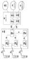
図1Aに示されるように、通信システム100は、無線送受信ユニット(WTRU)102a、102b、102c、102d、無線アクセスネットワーク(RAN)104、コアネットワーク106、公衆交換電話網(PSTN)108、インターネット110、およびその他のネットワーク112を含み得るが、開示された実施形態は、任意の数のWTRU、基地局、ネットワーク、および/またはネットワーク要素を考慮することが理解されるであろう。WTRU102a、102b、102c、102dのそれぞれは、無線環境内で動作および/または通信するように構成された任意の種類のデバイスであってもよい。例として、WTRU102a、102b、102c、102dは、無線信号を送信および/または受信するように構成可能であり、ユーザ機器(UE)、移動局、固定または移動加入者ユニット、ページャ、セルラ電話、携帯情報端末(PDA)、スマートフォン、ラップトップ、ネットブック、パーソナルコンピュータ、無線センサー、家庭用電化製品などを含み得る。As shown in FIG. 1A, the
通信システム100は、基地局114aおよび基地局114bも含み得る。基地局114a、114bのそれぞれは、コアネットワーク106、インターネット110、および/またはネットワーク112などの1つまたは複数の通信ネットワークへのアクセスを容易にするために、WTRU102a、102b、102c、102dのうちの少なくとも1つと無線でインターフェースをとるように構成された任意の種類のデバイスであってもよい。例として、基地局114a、114bは、無線基地局(BTS)、Node-B、eNodeB、ホームNodeB、ホームeNodeB、サイトコントローラ、アクセスポイント(AP)、無線ルータなどであってもよい。基地局114a、114bはそれぞれ単一の要素として示されているが、基地局114a、114bは、任意の数の相互に接続された基地局および/またはネットワーク要素を含み得ることが理解されるであろう。The
基地局114aは、RAN104の一部であることができ、RAN104は、その他の基地局、および/または基地局コントローラ(BSC)、無線ネットワークコントローラ(RNC)、中継ノードなどのネットワーク要素(図示せず)も含み得る。基地局114aおよび/または基地局114bは、セルと呼ばれる場合がある特定の地理的領域(図示せず)内で無線信号を送信および/または受信するように構成され得る。セルは、セルのセクタにさらに分割され得る。例えば、基地局114aに関連するセルは、3つのセクタに分割され得る。したがって、一実施形態において、基地局114aは、3つのトランシーバ、すなわち、セルの各セクタに対して1つのトランシーバを含み得る。別の実施形態において、基地局114aは、多入力多出力(MIMO)技術を使用することができ、したがって、セルの各セクタに対して複数のトランシーバを利用してもよい。The
基地局114a、114bは、任意の好適な無線通信リンク(例えば、無線周波数(RF)、マイクロ波、赤外線(IR)、紫外線(UV)、可視光など)である可能性がある無線インターフェース116を介してWTRU102a、102b、102c、102dのうちの1つまたは複数と通信することができる。無線インターフェース116は、任意の好適な無線アクセス技術(RAT)を用いて確立され得る。The
より具体的には、上述のように、通信システム100は、多元接続システムである可能性があり、CDMA、TDMA、FDMA、OFDMA、SC-FDMAなどの1つまたは複数のチャネルアクセススキームを使用する可能性がある。例えば、RAN104内の基地局114a、およびWTRU102a、102b、102cは、広帯域CDMA(WCDMA(登録商標))を用いて無線インターフェース116を確立することができるUMTS(Universal Mobile Telecommunications System)UTRA(Terrestrial Radio Access)などの無線技術を実装することができる。WCDMAは、HSPA(High-Speed Packet Access)および/またはHSPA+(Evolved HSPA)などの通信プロトコルを含み得る。HSPAは、HSDPA(High-Speed Downlink Packet Access)および/またはHSUPA(High-Speed Uplink Packet Access)を含み得る。More specifically, as mentioned above, the
別の実施形態において、基地局114aおよびWTRU102a、102b、102cは、LTE(Long Term Evolution)および/またはLTE-A(LTE-Advanced)を用いて無線インターフェース116を確立することができるE-UTRA(Evolved UMTS Terrestrial Radio Access)などの無線技術を実装することができる。In another embodiment, the
その他の実施形態において、基地局114aおよびWTRU102a、102b、102cは、IEEE802.16(すなわち、WiMAX(Worldwide Interoperability for Microwave Access))、CDMA2000、CDMA2000 1X、CDMA2000 EV-DO、IS-2000(Interim Standard 2000)、IS-95(Interim Standard 95)、IS-856(Interim Standard 856)、GSM(登録商標)(Global System for Mobile communications)、EDGE(Enhanced Data rates for GSM Evolution)、GERAN(GSM EDGE Radio Access Network)などの無線技術を実装することができる。In other embodiments, the
図1Aの基地局114bは、例えば、無線ルータ、ホームNodeB、ホームeNodeB、またアクセスポイントである可能性があり、事業所、家庭、車両、キャンパスなどの局所的な地域で無線接続を容易にするための任意の好適なRATを利用することができる。一実施形態において、基地局114bおよびWTRU102c、102dは、無線ローカルエリアネットワーク(WLAN)を確立するためのIEEE802.11などの無線技術を実装することができる。別の実施形態において、基地局114bおよびWTRU102c、102dは、無線パーソナルエリアネットワーク(WPAN)を確立するためのIEEE802.15などの無線技術を実装することができる。さらに別の実施形態において、基地局114bおよびWTRU102c、102dは、セルラに基づくRAT(例えば、WCDMA、CDMA2000、GSM、LTE、LTE-Aなど)を利用してピコセルまたはフェムトセルを確立することができる。図1Aに示されたように、基地局114bは、インターネット110に直接接続する可能性がある。したがって、基地局114bは、コアネットワーク106を介してインターネット110にアクセスするように要求されない可能性がある。1A may be, for example, a wireless router, a Home NodeB, a Home eNodeB, or an access point, and may utilize any suitable RAT to facilitate wireless connectivity in a localized area, such as an office, a home, a vehicle, a campus, etc. In one embodiment, the
RAN104は、コアネットワーク106と通信している可能性があり、コアネットワーク106は、WTRU102a、102b、102c、102dのうちの1つまたは複数に音声、データ、アプリケーション、および/またはボイスオーバーインターネットプロトコル(VoIP)サービスを提供するように構成された任意の種類のネットワークである可能性がある。例えば、コアネットワーク106は、呼制御、課金サービス、モバイルの位置に基づくサービス、プリペイド電話、インターネット接続、映像配信などを提供し、および/またはユーザ認証などの高レベルのセキュリティ機能を実行することができる。図1Aには示されていないが、RAN104および/またはコアネットワーク106は、RAN104と同じRAT、または異なるRATを使用するその他のRANと直接的または間接的に通信している可能性があることが理解されるであろう。例えば、E-UTRA無線技術を利用している可能性があるRAN104に接続されることに加えて、コアネットワーク106は、GSM無線技術を使用する別のRAN(図示せず)とも通信している可能性がある。
コアネットワーク106は、WTRU102a、102b、102c、102dがPSTN108、インターネット110、および/またはその他のネットワーク112にアクセスするためのゲートウェイとしても働くことができる。PSTN108は、POTS(plain old telephone service)を提供する回線交換電話ネットワークを含み得る。インターネット110は、TCP/IPインターネットプロトコルスイートの伝送制御プロトコル(TCP)、ユーザデータグラムプロトコル(UDP)、およびインターネットプロトコル(IP)などの共通の通信プロトコルを使用する相互に接続されたコンピュータネットワークおよびデバイスの全世界的なシステムを含み得る。ネットワーク112は、その他のサービスプロバイダによって所有および/または運用される有線または無線通信ネットワークを含み得る。例えば、ネットワーク112は、RAN104と同じRATまたは異なるRATを使用する可能性がある1つまたは複数のRANに接続された別のコアネットワークを含み得る。The
通信システム100のWTRU102a、102b、102c、102dの一部またはすべては、マルチモード機能を含む可能性があり、すなわち、WTRU102a、102b、102c、102dは、異なる無線リンクを介して異なる無線ネットワークと通信するための複数のトランシーバを含む可能性がある。例えば、図1Aに示されたWTRU102cは、セルラに基づく無線技術を使用することができる基地局114aおよびIEEE802無線技術を使用することができる基地局114bと通信するように構成され得る。Some or all of the
図1Bは、例示的なWTRU102のシステム図である。図1Bに示されたように、WTRU102は、プロセッサ118、トランシーバ120、送信/受信要素122、スピーカー/マイクロホン124、キーパッド126、ディスプレイ/タッチパッド128、取り外し不可能なメモリ130、取り外し可能なメモリ132、電源134、GPS(global positioning system)チップセット136、およびその他の周辺機器138を含み得る。WTRU102は、実施形態に準拠したまま、上述の要素の任意の部分的な組み合わせを含み得ることが理解されるであろう。1B is a system diagram of an
プロセッサ118は、汎用プロセッサ、専用プロセッサ、通常のプロセッサ、デジタル信号プロセッサ(DSP)、複数のマイクロプロセッサ、DSPコアと関連する1つまたは複数のマイクロプロセッサ、コントローラ、マイクロコントローラ、特定用途向け集積回路(ASIC)、フィールドプログラマブルゲートアレイ(FPGA)回路、任意のその他の種類の集積回路(IC)、状態機械などである可能性がある。プロセッサ118は、信号の符号化、データ処理、電力制御、入力/出力処理、および/またはWTRU102が無線環境で動作することを可能にする任意のその他の機能を実行することができる。プロセッサ118は、トランシーバ120に結合されることができ、トランシーバ120は、送信/受信要素122に結合されることができる。図1Bはプロセッサ118およびトランシーバ120を別個のコンポーネントとして示すが、プロセッサ118およびトランシーバ120は、電子的なパッケージまたはチップに一緒に統合され得ることが理解されるであろう。The
送信/受信要素122は、無線インターフェース116を介して基地局(例えば、基地局114a)に信号を送信するか、または基地局(例えば、基地局114a)から信号を受信するように構成され得る。例えば、一実施形態において、送信/受信要素122は、RF信号を送信および/または受信するように構成されたアンテナである可能性がある。別の実施形態において、送信/受信要素122は、例えば、IR、UV、または可視光信号を送信および/または受信するように構成されたエミッタ/ディテクタである可能性がある。さらに別の実施形態において、送信/受信要素122は、RF信号と光信号の両方を送信および受信するように構成され得る。送信/受信要素122は、無線信号の任意の組み合わせを送信および/または受信するように構成され得ることが理解されるであろう。The transmit/receive
加えて、送信/受信要素122は、図1Bにおいて単一の要素として示されているが、WTRU102は、任意の数の送信/受信要素122を含み得る。より具体的には、WTRU102は、MIMO技術を使用することができる。したがって、一実施形態において、WTRU102は、無線インターフェース116を介して無線信号を送信および受信するために2つ以上の送信/受信要素122(例えば、複数のアンテナ)を含み得る。In addition, although the transmit/receive
トランシーバ120は、送信/受信要素122によって送信されることになる信号を変調し、送信/受信要素122によって受信される信号を復調するように構成され得る。上述のように、WTRU102は、マルチモード機能を有する可能性がある。したがって、トランシーバ120は、WTRU102が例えばUTRAおよびIEEE802.11などの複数のRATを介して通信することを可能にするための複数のトランシーバを含み得る。The
WTRU102のプロセッサ118は、スピーカー/マイクロホン124、キーパッド126、および/またはディスプレイ/タッチパッド128(例えば、液晶ディスプレイ(LCD)ディスプレイユニットまたは有機発光ダイオード(OLED)ディスプレイユニット)に結合されることができ、それらからユーザ入力データを受信することができる。プロセッサ118は、スピーカー/マイクロホン124、キーパッド126、および/またはディスプレイ/タッチパッド128にユーザデータを出力することもできる。さらに、プロセッサ118は、取り外し不可能なメモリ130および/または取り外し可能なメモリ132などの任意の種類の好適なメモリからの情報にアクセスし、それらのメモリにデータを記憶することができる。取り外し不可能なメモリ130は、ランダムアクセスメモリ(RAM)、読み出し専用メモリ(ROM)、ハードディスク、または任意のその他の種類のメモリストレージデバイスを含み得る。取り外し可能なメモリ132は、加入者識別モジュール(SIM)カード、メモリスティック、セキュアデジタル(SD)メモリカードなどを含み得る。その他の実施形態において、プロセッサ118は、サーバまたはホームコンピュータ(図示せず)などの、WTRU102に物理的に置かれていないメモリからの情報にアクセスし、そのメモリにデータを記憶することができる。The
プロセッサ118は、電源134から電力を受け取ることができ、WTRU102内のその他のコンポーネントに電力を分配し、および/またはその電力を制御するように構成され得る。電源134は、WTRU102に給電するための任意の好適なデバイスである可能性がある。例えば、電源134は、1つまたは複数の乾電池(例えば、ニッケルカドミウム(NiCd)、ニッケル亜鉛(NiZn)、ニッケル水素(NiMH)、リチウムイオン(Li-ion)など)、太陽電池、燃料電池などを含み得る。The
プロセッサ118は、GPSチップセット136にも結合されることができ、GPSチップセット136は、WTRU102の現在位置に関する位置情報(例えば、経度および緯度)を提供するように構成され得る。GPSチップセット136からの情報に加えて、またはGPSチップセット136からの情報の代わりに、WTRU102は、基地局(例えば、基地局114a、114b)から無線インターフェース116を介して位置情報を受信し、および/または2つ以上の近隣の基地局から受信されている信号のタイミングに基づいてそのWTRU102の位置を判定することができる。WTRU102は、実施形態に準拠したまま、任意の好適な位置判定方法によって位置情報を取得することができることが理解されるであろう。The
プロセッサ118は、その他の周辺機器138にさらに結合されることができ、その他の周辺機器138は、追加的な特徴、機能、および/または有線もしくは無線接続を提供する1つまたは複数のソフトウェアおよび/またはハードウェアモジュールを含み得る。例えば、周辺機器138は、加速度計、電子コンパス、衛星トランシーバ、デジタルカメラ(写真または動画用)、USB(universal serial bus)ポート、振動デバイス、テレビトランシーバ、ハンズフリーヘッドセット、Bluetooth(登録商標)モジュール、FM(frequency modulated)ラジオユニット、デジタル音楽プレーヤー、メディアプレーヤー、ビデオゲームプレーヤーモジュール、インターネットブラウザなどを含み得る。The
図1Cは、一実施形態によるRAN104およびコアネットワーク106のシステム図である。上述のように、RAN104は、無線インターフェース116を介してWTRU102a、102b、102cと通信するためにUTRA無線技術を使用する可能性がある。RAN104は、コアネットワーク106とも通信している可能性がある。図1Cに示されるように、RAN104はNode-B140a、140b、140cを含むことができ、Node-B140a、140b、140cは、無線インターフェース116を介してWTRU102a、102b、102cと通信するための1つまたは複数のトランシーバをそれぞれが含み得る。Node-B140a、140b、140cは、RAN104内の特定のセル(図示せず)にそれぞれが関連付けられ得る。RAN104は、RNC142a、142bも含み得る。RAN104は、実施形態に準拠したまま、任意の数のNode-BおよびRNCを含み得ることが理解されるであろう。1C is a system diagram of the
図1Cに示されるように、Node-B140a、140bは、RNC142aと通信している可能性がある。加えて、Node-B140cは、RNC142bと通信している可能性がある。Node-B140a、140b、140cは、Iubインターフェースを介してそれぞれのRNC142a、142bと通信することができる。RNC142a、142bは、Iurインターフェースを介して互いに通信している可能性がある。RNC142a、142bのそれぞれは、そのRNCが接続されているそれぞれのNode-B140a、140b、140cを制御するように構成され得る。さらに、RNC142a、142bのそれぞれは、アウターループ電力制御、負荷制御、アドミッション制御、パケットのスケジューリング、ハンドオーバ制御、マクロダイバーシティ(macrodiversity)、セキュリティ機能、データの暗号化などのその他の機能を実行またはサポートするように構成され得る。1C, Node-
図1Cに示されるコアネットワーク106は、MGW(media gateway)144、MSC(mobile switching center)146、SGSN(serving GPRS support node)148、および/またはGGSN(gateway GPRS support node)150を含み得る。上述の要素のそれぞれはコアネットワーク106の一部として示されているが、これらの要素のうちの任意の要素は、コアネットワークの運用者以外の主体によって所有および/または運用される可能性があることが理解されるであろう。The
RAN104のRNC142aは、IuCSインターフェースを介してコアネットワーク106のMSC146に接続され得る。MSC146は、MGW144に接続され得る。MSC146およびMGW144は、WTRU102a、102b、102cがPSTN108などの回線交換ネットワークにアクセスできるようにして、WTRU102a、102b、102cと従来の固定電話回線通信デバイスの間の通信を容易にすることができる。The
RAN104のRNC142aは、IuPSインターフェースを介してコアネットワーク106のSGSN148にやはり接続され得る。SGSN148は、GGSN150に接続され得る。SGSN148およびGGSN150は、WTRU102a、102b、102cがインターネット110などのパケット交換ネットワークにアクセスできるようにして、WTRU102a、102b、102cとIP対応デバイスの間の通信を容易にすることができる。The
上述のように、コアネットワーク106は、その他のサービスプロバイダによって所有および/または運用されるその他の有線または無線ネットワークを含み得るネットワーク112にも接続され得る。As mentioned above, the
以下の実施形態は、例として、WCDMAに関連して説明される。以下で開示される実施形態は、LTE(Long Term Evolution)、cdma2000、WiMaxなどを含むがこれらに限定されない任意の無線通信システムに適用され得ることに留意されたい。これらの実施形態は、例として、2つの送信アンテナを用いたアップリンクのデュアルストリームの送信に関連して説明されるが、これらの実施形態は、3つ以上の送信アンテナを用いた送信の3つ以上のストリームに適用され得ることにも留意されたい。The following embodiments are described in the context of WCDMA, by way of example. It should be noted that the embodiments disclosed below may be applied to any wireless communication system, including, but not limited to, LTE (Long Term Evolution), cdma2000, WiMax, etc. It should also be noted that while the embodiments are described in the context of uplink dual stream transmissions using two transmit antennas, by way of example, the embodiments may be applied to three or more streams of transmissions using three or more transmit antennas.
以降、用語「第1のパイロット」と「主(primary)パイロット」が交換可能なように使用され、「第2のパイロット」と「副(secondary)パイロット」が交換可能なように使用される。「パイロットシーケンス」(またはパイロット信号もしくはパイロットシンボル)は、DPCCH(dedicated physical control channel)などの、パイロットシーケンスを搬送する制御チャネルを指す可能性がある。DPCCHは、パイロットチャネルの例として使用される。以降、用語「第1のDPCCH」、「主DPCCH」、および「DPCCH1」は交換可能なように使用され、用語「第2のDPCCH」、「副DPCCH」、「S-DPCCH」、および「DPCCH2」は交換可能なように使用される。Hereinafter, the terms "first pilot" and "primary pilot" are used interchangeably, and "secondary pilot" and "secondary pilot" are used interchangeably. "Pilot sequence" (or pilot signal or pilot symbol) may refer to a control channel that carries the pilot sequence, such as a dedicated physical control channel (DPCCH). DPCCH is used as an example of a pilot channel. Hereinafter, the terms "first DPCCH", "primary DPCCH", and "DPCCH1" are used interchangeably, and the terms "secondary DPCCH", "secondary DPCCH", "S-DPCCH", and "DPCCH2" are used interchangeably.
WTRUは、2つ(以上)のアンテナを介して2つ(以上)のパイロットシーケンス(すなわち、サウンディングチャネル(sounding channel)または参照信号)を送信することができる。それらのパイロットシーケンスは、直交している可能性があり、または直交していない可能性がある。第1のおよび第2のパイロットシーケンスは、異なるアンテナで送信されるか、またはプリコーディングされ、異なるビームで2つのアンテナを介して送信される可能性がある。図2は、WTRU200がプリコーディングせずに2つのアンテナ208を介して2つのパイロットシーケンスを送信する例を示す。第1のおよび第2のパイロットシーケンスは、それぞれ、変調マッパ(modulation mapper)202によって変調され、拡散ブロック204によって拡散され、スクランブルブロック206によってスクランブリング符号と掛け合わされ、2つのアンテナ208を介して送信される。パイロットシーケンス(例えば、DPCCH1およびDPCCH2)は、例として、図16に示されるようにプリコーディングされる可能性がある。図16においては、第1のDPCCHならびにその他のアップリンクチャネル(例えば、E-DPDCH、E-DPCCH、DPDCH、およびHS-DPCCH)が、ベクトル1を用いてプリコーディングブロック1602によってプリコーディングされ、第2のDPCCHが、第1のDPCCHおよびその他のアップリンクチャネルに適用されるプリコーディングベクトル1に対する位相の変化を有するベクトル2を用いてプリコーディングブロック1604によってプリコーディングされる。The WTRU may transmit two (or more) pilot sequences (i.e., sounding channels or reference signals) via two (or more) antennas. The pilot sequences may be orthogonal or non-orthogonal. The first and second pilot sequences may be transmitted on different antennas or may be precoded and transmitted via the two antennas on different beams. FIG. 2 shows an example in which the
WTRUが、シングルストリームまたはデュアルストリーム(すなわち、UL MIMO)の閉ループ送信ダイバーシティ(closed loop transmit diversity)(CLTD)で動作しているとき、受信機(例えば、NodeB)は、パイロットシーケンスを用いて空間チャネルを推定して、整合性を保ってデータを復調または検波し、NodeBへの次の送信のためにWTRUで使用されるべき最良のアップリンクのプリコーディングの重みを決定することができる。When the WTRU is operating in single-stream or dual-stream (i.e., UL MIMO) closed loop transmit diversity (CLTD), the receiver (e.g., NodeB) can estimate the spatial channel using the pilot sequence to coherently demodulate or detect the data and determine the best uplink precoding weights to be used by the WTRU for the next transmission to the NodeB.
WTRUは、以下の場合のうちの少なくとも1つの場合に第2のパイロット(例えば、副DPCCH)を送信する可能性がある。(1)(例えば、E-DCH(enhanced dedicated channel)で)送信されているデータがあるとき、(2)送信されている2つのデータストリームがあるとき、(3)周期的に、(4)圧縮モードのギャップの間に、(4)第1のパイロットと一緒に、(5)2つのデータストリームがあるときに第1のパイロットと一緒に、(6)送信されているデータがあるときに第1のパイロットと一緒に、(7)送信されているデータがないときに第1のパイロットと一緒に、または(8)第1のパイロットの代わりに周期的に(例えば、N回の送信機会ごとに1回、あるいはNスロットごとに1回、N個のTTIごとに1回など)。オーバーヘッドを減らすために、副パイロットは、間欠的に送信され、および/または主パイロットと比較して低電力で送信される可能性がある。The WTRU may transmit a second pilot (e.g., a secondary DPCCH) in at least one of the following cases: (1) when there is data being transmitted (e.g., on an enhanced dedicated channel (E-DCH)), (2) when there are two data streams being transmitted, (3) periodically, (4) during compressed mode gaps, (4) together with the first pilot, (5) together with the first pilot when there are two data streams, (6) together with the first pilot when there is data being transmitted, (7) together with the first pilot when there is no data being transmitted, or (8) periodically instead of the first pilot (e.g., once every N transmission opportunities, or once every N slots, once every N TTIs, etc.). To reduce overhead, the secondary pilot may be transmitted intermittently and/or at a lower power compared to the primary pilot.
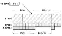
パイロットシーケンスがプリコーディングされる場合、第2のビームで送信される第2のパイロットシーケンスは、データ変調の観点から見るとオーバーヘッドと見なされ得る。オーバーヘッドを減らすために、WTRUは、周期的に、ほんのわずかな時間、第2のパイロットシーケンスを送信する可能性がある。第2のパイロットシーケンスのデューティサイクルは、NodeBまたは任意のその他のネットワークエンティティによって構成され得る。プリコーディングの重みの変更は、アップリンクのE-DCHのサブフレーム(例えば、2msまたは10msの送信時間間隔(TTI))に合わせられ得る。送信およびNodeBの処理での遅延を考慮するために、第2のパイロットは、サブフレームの境界の前に送信され得る。図3は、WTRUがサブフレームの境界の2スロット前の(網掛けのスロットの間に)第2のパイロットシーケンスを送信する例を示す。これは、NodeBの処理に関する1スロットの遅延と、(1スロットの物理レイヤメッセージを想定した)新しいプリコーディングの重みの情報をWTRUに送信するためのもう1スロットとを許容する。If the pilot sequence is precoded, the second pilot sequence transmitted on the second beam may be considered as overhead from the data modulation point of view. To reduce overhead, the WTRU may transmit the second pilot sequence periodically for a small amount of time. The duty cycle of the second pilot sequence may be configured by the NodeB or any other network entity. The precoding weight change may be aligned to the uplink E-DCH subframe (e.g., 2 ms or 10 ms transmission time interval (TTI)). To account for delays in transmission and NodeB processing, the second pilot may be transmitted before the subframe boundary. Figure 3 shows an example where the WTRU transmits the second pilot sequence two slots before the subframe boundary (during the shaded slots). This allows for one slot of delay for NodeB processing and one more slot for transmitting new precoding weight information to the WTRU (assuming a one-slot physical layer message).
第2のパイロットは、より低いレートで(例えば、Nスロット、Nサブフレーム、またはNフレームごとなどで)送信される可能性があり、複数の連続するスロットまたはバーストのグループで送信される可能性がある。(電力オフセット、タイミングの遅延、レート、およびバーストサイズなどの)第2のパイロットに関する動作パラメータは、RRCシグナリングを用いてネットワークによって構成される可能性があり、またはこれらのパラメータの一部(例えば、タイミング、バーストサイズなど)は、仕様で構成される可能性がある。The second pilot may be transmitted at a lower rate (e.g., every N slots, N subframes, or N frames) and may be transmitted in groups of multiple consecutive slots or bursts. Operating parameters for the second pilot (such as power offset, timing delay, rate, and burst size) may be configured by the network using RRC signaling, or some of these parameters (e.g., timing, burst size, etc.) may be configured in the specification.
あるいは、第2のDPCCHのオーバーヘッドを減らすために、DPCCHのDTX動作が、DPCCHごとに制御され得る。2つのULのDTXの状態変数、UL_DTX_Active(1)およびUL_DTX_Active(2)が、第1のDPCCHおよび第2のDPCCHに関して定義され、個々に保持され、評価され得る。WTRUは、第1のDPCCHおよび第2のDPCCHの送信をDPCCHごとに制御することができる。Alternatively, to reduce the overhead of the second DPCCH, the DTX operation of the DPCCH may be controlled on a per-DPCCH basis. Two UL DTX state variables, UL_DTX_Active(1) and UL_DTX_Active(2), may be defined for the first DPCCH and the second DPCCH and maintained and evaluated individually. The WTRU may control the transmission of the first DPCCH and the second DPCCH on a per-DPCCH basis.
一例においては、第1のストリームまたはアンテナの第1のDPCCHおよびその他のチャネルが連続的に送信され得る間に第2のDPCCHが周期的に間欠送信されるように、UL_DTX_Active(1)が「偽」に設定される可能性があり、UL_DTX_Active(2)が「真」に設定される可能性がある。In one example, UL_DTX_Active(1) may be set to "false" and UL_DTX_Active(2) may be set to "true" such that the second DPCCH is periodically and intermittently transmitted while the first DPCCH and other channels of the first stream or antenna may be transmitted continuously.
別の例においては、UL_DTX_Active(1)とUL_DTX_Active(2)の両方が「真」に設定されるが、第1のDPCCHの送信を許可しながら第2のDPCCHを間欠的に送信するために第1のおよび第2のDPCCHに関して異なるDPCCHのバーストパターンが構成される可能性がある。In another example, both UL_DTX_Active(1) and UL_DTX_Active(2) may be set to "true", but different DPCCH burst patterns may be configured for the first and second DPCCH to transmit the second DPCCH intermittently while allowing transmission of the first DPCCH.
準静的なWTRUのアンテナ構成と組み合わせて、S-DPCCHのために、S-DPCCHに固有のDTXパターンまたはサイクルが定義され得る。例えば、S-DPCCHに固有のDTXパターンまたはサイクルは、WTRUのアンテナ構成の状態にリンクされ得る。WTRUは、S-DPCCHに関する2つ以上のS-DPCCHに固有のDTXパターンまたはサイクルを用いて動作するように構成される可能性があり、少なくとも1つのS-DPCCHに固有のDTXパターンまたはサイクルのアクティブ化の状態は、WTRUのアンテナ構成の状態(例えば、WTRUがUL CLTDで動作しているか否か、またはWTRUが、アップリンクチャネルが2つのアンテナのうちの一方で送信され、S-DPCCHが他方のアンテナで送信されるようにして動作するように構成されているかどうか)にリンクされ得る。表1は、例示的なWTRUのアンテナ構成を示す。構成の一部は、サポートされない可能性がある。WTRUは、HS-SCCH命令またはRRCシグナリングによってその他の構成のうちの1つを使用するように構成され得る。In combination with the semi-static WTRU antenna configuration, an S-DPCCH-specific DTX pattern or cycle may be defined for the S-DPCCH. For example, the S-DPCCH-specific DTX pattern or cycle may be linked to the state of the WTRU antenna configuration. The WTRU may be configured to operate with more than one S-DPCCH-specific DTX pattern or cycle for the S-DPCCH, and the activation state of at least one S-DPCCH-specific DTX pattern or cycle may be linked to the state of the WTRU antenna configuration (e.g., whether the WTRU is operating in UL CLTD or not, or whether the WTRU is configured to operate with uplink channels transmitted on one of two antennas and the S-DPCCH transmitted on the other antenna). Table 1 shows an exemplary WTRU antenna configuration. Some of the configurations may not be supported. The WTRU may be configured to use one of the other configurations via HS-SCCH command or RRC signaling.

1つの実装において、WTRUは、S-DPCCHに関する2つのS-DPCCHに固有のDTXパターンまたはサイクルを用いて構成され得る。WTRUは、例えば、RRCシグナリングによって、これらのS-DPCCHに固有のDTXパターンまたはサイクルのパラメータを用いて構成され得る。これらのパラメータのうちの1つまたは複数は、仕様で決められている可能性がある。In one implementation, the WTRU may be configured with two S-DPCCH-specific DTX patterns or cycles for the S-DPCCH. The WTRU may be configured with parameters for these S-DPCCH-specific DTX patterns or cycles, for example, by RRC signaling. One or more of these parameters may be specified.
WTRUは、そのWTRUが通常のUL CLTDモード(すなわち、表1の構成#1)で動作するように構成されるとき、第1の(短い)S-DPCCHに固有のDTXパターンまたはサイクルを適用する。WTRUは、通常のDPCCHのDTXのアクティブ化の状態に関係なくこのS-DPCCHに固有のDTXパターンを適用するように構成され得る。そして、WTRUは、そのWTRUがS-DPCCHがダイバーシティアンテナで送信される「アンテナ切り替え」モード(例えば、表1の構成#2および構成#3)で動作するように構成されるとき、第2の(長い)S-DPCCHに固有のDTXパターンまたはサイクルを適用する可能性がある。図4は、S-DPCCHに固有のDTXパターンまたはサイクルの例示的な実装を示す。図4において、WTRUは、構成#1(すなわち、UL CLTDモードでの動作)に構成され、それから、HS-SCCH命令によって構成#2または#3に構成される。The WTRU applies a specific DTX pattern or cycle to the first (shorter) S-DPCCH when the WTRU is configured to operate in normal UL CLTD mode (i.e.,
別の実装において、WTRUは、S-DPCCHに関する単一の(長い)S-DPCCHに固有のDTXパターンまたはサイクルを用いて構成され得る。WTRUは、そのWTRUがアンテナ切り替えモード(すなわち、構成#2および#3)に構成されるとき、その(長い)DTXパターンを適用する可能性がある。WTRUがアンテナ切り替えモードに構成されないとき、S-DPCCHに固有のDTXパターンまたはサイクルは適用されない可能性がある。図5は、単一のS-DPCCHに固有のDTXパターンまたはサイクルの例示的な実装を示す。図5において、WTRUは、構成#1(UL CLTDモードでの動作)に構成され、それから、HS-SCCH命令によって構成#2または#3に構成される。In another implementation, the WTRU may be configured with a single (long) S-DPCCH-specific DTX pattern or cycle for the S-DPCCH. The WTRU may apply that (long) DTX pattern when the WTRU is configured in antenna switching mode (i.e., configurations #2 and #3). When the WTRU is not configured in antenna switching mode, the S-DPCCH-specific DTX pattern or cycle may not be applied. Figure 5 shows an example implementation of a single S-DPCCH-specific DTX pattern or cycle. In Figure 5, the WTRU is configured in configuration #1 (operating in UL CLTD mode) and then configured in configuration #2 or #3 by HS-SCCH command.
上述の実装の両方において、WTRUは、S-DPCCHを完全に非アクティブ化することに実質的に等しい無限に長いDTXサイクルを用いて構成され得る。したがって、表1の構成#4および#5は、無限のDTXサイクルを用いる構成#2および#3と同一になり得る。In both of the above implementations, the WTRU may be configured with an infinitely long DTX cycle, which is essentially equivalent to completely deactivating the S-DPCCH. Thus,
例えば、通常のDPCCHのCPCのDTXメカニズムにリンクされた追加的なDTXが、S-DPCCHに固有のDTXに加えて適用され得る。例えば、WTRUは、主DPCCHも送信されるときにS-DPCCHを送信するように構成され得る。For example, an additional DTX linked to the DTX mechanism of the CPC of the normal DPCCH may be applied in addition to the DTX specific to the S-DPCCH. For example, the WTRU may be configured to transmit the S-DPCCH when the primary DPCCH is also transmitted.
S-DPCCHに固有のDTXパターンは、HS-SCCH命令またはその他のシグナリングによって動的にアクティブ化および非アクティブ化され得る。S-DPCCHに固有のDTXパターンまたはサイクルのアクティブ化の状態は、通常のDPCCHのDTXのアクティブ化の状態にリンクされ得る。S-DPCCHに固有のDTXパターンまたはサイクルは、通常のDPCCHのDTXがアクティブ化/非アクティブ化されるときにいつもアクティブ化/非アクティブ化される可能性がある。The S-DPCCH specific DTX pattern may be dynamically activated and deactivated by HS-SCCH commands or other signaling. The activation state of the S-DPCCH specific DTX pattern or cycle may be linked to the activation state of the normal DPCCH DTX. The S-DPCCH specific DTX pattern or cycle may be activated/deactivated whenever the normal DPCCH DTX is activated/deactivated.
デュアルストリーム動作において、NodeBは、第2のパイロットを用いて第2のストリームのデータを復調することができる。これは、より優れたチャネル推定を必要とする可能性がある。一実施形態において、WTRUは、第2のストリームが送信されるときに異なる(例えば、より高い)電力設定で連続的に第2のパイロットを送信する可能性がある。図6は、2つのE-DCHストリーム、および第2のE-DCHが送信される間にそれぞれ異なる電力設定を用いる2つのDPCCHの例示的な送信を示す。図6において、第2のDPCCHは、第2のE-DCHストリーム(604)が送信されるとき、より高い電力レベル(602)で送信される。In dual stream operation, the NodeB may demodulate the data of the second stream using the second pilot. This may require better channel estimation. In one embodiment, the WTRU may transmit the second pilot continuously at a different (e.g., higher) power setting when the second stream is transmitted. Figure 6 shows an example transmission of two E-DCH streams and two DPCCHs, each with a different power setting while the second E-DCH is transmitted. In Figure 6, the second DPCCH is transmitted at a higher power level (602) when the second E-DCH stream (604) is transmitted.
WTRUは、第2のストリームのデータを搬送するサブフレームの始まりの前に、通常の周期的な電力レベルに比べてより高い電力レベルで第2のパイロットを送信する可能性がある。WTRUは、第2のストリームのデータを搬送するサブフレームが終わった後により高い電力レベルで第2のパイロットを送信する可能性がある。これは、NodeBがデータの復調のためにそのNodeBのチャネル推定をさらに改善することを可能にすることができる。The WTRU may transmit the second pilot at a higher power level compared to the normal periodic power level before the beginning of the subframe carrying the second stream data. The WTRU may transmit the second pilot at a higher power level after the end of the subframe carrying the second stream data. This may allow the NodeB to further improve its channel estimation for demodulation of the data.
WTRUは、NodeBがWTRUをデュアルストリームモードに構成するときにより高い電力レベルで第2のパイロットを送信する可能性がある。これは、NodeBがチャネルの符号化のためにそのNodeBのチャネル推定をさらに改善することを可能にする。これは、WTRUに、ネットワークによる指示を受信した後により高い電力で第2のパイロットを送信させることによって実現され得る。あるいは、WTRUは、周期的により高い電力レベルで第2のパイロットを送信する可能性がある。The WTRU may transmit the second pilot at a higher power level when the NodeB configures the WTRU in dual stream mode. This allows the NodeB to further improve its channel estimation for channel encoding. This may be achieved by having the WTRU transmit the second pilot at a higher power after receiving an indication by the network. Alternatively, the WTRU may transmit the second pilot at a higher power level periodically.
WTRUは、制御データを有するチャネル(例えば、DPCCH)で第2のパイロットが送信される場合に、より高い電力レベルで第2のパイロットを送信する可能性がある。デュアルストリーム動作が、独立したE-DCHトランスポートフォーマットコンビネーション(E-TFC)の選択がストリームのそれぞれに対して行われることを許可する場合、独立した制御データおよび独立したパイロットが、各ストリームに関して送信され得る。一実施形態において、WTRUは、2つの独立したDPCCH(第1のおよび第2のDPCCH)を送信する可能性がある。あるいは、WTRUは、一方のDPCCHで両方のストリームに関する制御データを送信し、他方のDPCCHで独立したパイロットシーケンスを送信する可能性がある。The WTRU may transmit the second pilot at a higher power level if the second pilot is transmitted on a channel (e.g., DPCCH) that carries control data. If dual stream operation allows independent E-DCH transport format combination (E-TFC) selection to be made for each of the streams, independent control data and independent pilots may be transmitted for each stream. In one embodiment, the WTRU may transmit two independent DPCCHs (first and second DPCCHs). Alternatively, the WTRU may transmit control data for both streams on one DPCCH and an independent pilot sequence on the other DPCCH.
あるいは、WTRUは、ULチャネルのランク(rank)の推定および/またはプリコーディングの重みの推定のための別個のサウンディングチャネルを送信する可能性がある。サウンディングチャネルは、NodeBがチャネルのランクおよび最適なプリコーディングを推定することができる既知の信号または1組の信号をNodeBに提供し得る。WTRUは、デュアルストリームが送信されるとき、サウンディングチャネルを送信しない可能性がある。サウンディングチャネルは、デュアルストリームが送信されないときに、周期的に送信される可能性がある。あるいは、サウンディングチャネルは、デュアルストリームの送信に関係なく周期的に送信される可能性がある。サウンディングチャネルは、NodeBによって提供され得るトリガイベントに基づいて送信される可能性がある。Alternatively, the WTRU may transmit a separate sounding channel for UL channel rank estimation and/or precoding weight estimation. The sounding channel may provide the NodeB with a known signal or set of signals from which the NodeB can estimate the channel rank and optimal precoding. The WTRU may not transmit the sounding channel when the dual stream is transmitted. The sounding channel may be transmitted periodically when the dual stream is not transmitted. Alternatively, the sounding channel may be transmitted periodically regardless of the transmission of the dual stream. The sounding channel may be transmitted based on a trigger event that may be provided by the NodeB.
サウンディングチャネルは、チャネルおよびスケジューリング情報をNodeBに提供することができる構成可能な1組の送信を含み得る。サウンディングチャネル上の送信は、利用可能なチャネルのプリコーディングを逐次的に、または並列的に、または何らかの所定の組み合わせで使用して送信され得る。例えば、サウンディングチャネルは、サブフレームに対して利用可能なプリコーディングの構成(またはプリコーディングの構成の定義されたサブセット)のそれぞれを用いてそのサウンディングチャネルの事前に定義された信号を順番に送信する可能性がある。次いで、NodeBは、プリコーディングの構成のそれぞれでのそのWTRUに関するチャネルの性能を推定することができる。サウンディングチャネルがいかなる制御情報も含まない場合、サウンディングチャネルは、制御情報を含むDPCCHの電力レベルよりも低い電力レベルで送信される可能性がある。あるいは、サウンディングチャネルは、プリコーディングがサウンディングチャネルに適用されない場合、利用可能なアンテナのそれぞれから順番に送信される可能性がある。The sounding channel may include a configurable set of transmissions that can provide channel and scheduling information to the NodeB. Transmissions on the sounding channel may be transmitted using available channel precoding sequentially, in parallel, or in some predefined combination. For example, the sounding channel may transmit a predefined signal of the sounding channel in sequence with each of the precoding configurations (or a defined subset of the precoding configurations) available for the subframe. The NodeB may then estimate the performance of the channel for that WTRU in each of the precoding configurations. If the sounding channel does not include any control information, the sounding channel may be transmitted at a power level lower than the power level of the DPCCH, which includes control information. Alternatively, the sounding channel may be transmitted in sequence from each of the available antennas if precoding is not applied to the sounding channel.
重みが変わったときの電力制御のための実施形態が、以降で開示される。WTRUがそのWTRUのプリコーディングの重みを変更するとき、その変更は、そのWTRUに関するNodeBの受信電力および信号対干渉比(SIR)に影響を与える可能性がある。NodeBがチャネルを推定し、最良のプリコーディングの重みを決定し、その情報をWTRUにシグナリングし、WTRUが新しい重みを適用する時間の間にチャネルが大きく変わらない場合、NodeBにおける受信電力の変化は正である。つまり、プリコーディングの重みの変更の後、WTRUに関するSIRがNodeBにおいて改善され、SIRがNodeBにおける目標SIRよりも高くなり、したがって、余分な雑音の増加を生じ、送信電力制御(TPC)のダウンコマンド(down command)をWTRUに発することをNodeBに強いる。そのような雑音の増加の行き過ぎおよび電力制御の不安定を防止するために、WTRUは、そのWTRUのアクティブセット(active set)のすべてのNodeBによって受信されたTPCコマンドに潜在的に依存して、プリコーディングの重みが変更されるときにそのWTRUの送信電力を調整することができる。An embodiment for power control when weights change is disclosed below. When a WTRU changes its precoding weights, the change can affect the received power and signal-to-interference ratio (SIR) at the NodeB for the WTRU. If the channel does not change significantly during the time that the NodeB estimates the channel, determines the best precoding weights, signals that information to the WTRU, and the WTRU applies the new weights, the change in received power at the NodeB is positive. That is, after a precoding weight change, the SIR for the WTRU improves at the NodeB, and the SIR becomes higher than the target SIR at the NodeB, thus causing an extra noise increase and forcing the NodeB to issue a transmit power control (TPC) down command to the WTRU. To prevent such excessive noise increase and power control instability, the WTRU can adjust its transmit power when precoding weights are changed, potentially relying on the TPC commands received by all NodeBs in the WTRU's active set.
一実施形態において、WTRUは、プリコーディングの重みが変更されるときに、構成された量(例えば、1dB)だけ第1のDPCCHの送信電力を削減するようにネットワークによって構成され得る。WTRUは、新しいプリコーディングの重みが適用されるスロットでDPCCHの電力を削減する(または代替的に維持する)可能性がある。DPCCHの電力を削減することによって、そのDPCCHの電力はその他の物理チャネルに関する電力の基準として使用されるので、WTRUの送信電力全体が削減される。In one embodiment, the WTRU may be configured by the network to reduce the transmit power of the first DPCCH by a configured amount (e.g., 1 dB) when the precoding weights are changed. The WTRU may reduce (or alternatively maintain) the power of the DPCCH in the slot where the new precoding weights are applied. By reducing the power of the DPCCH, the overall transmit power of the WTRU is reduced since the power of the DPCCH is used as a reference for the power for other physical channels.
別の実施形態において、WTRUは、TPCコマンドをオーバーライドする可能性がある。WTRUは、プリコーディングの重みの変更が行われるスロットに関するTPCコマンドを無視し、TPCの「ダウン」コマンドを適用する可能性がある。あるいは、WTRUは、TPCコマンドをオーバーライドすることによってDPCCHの電力を維持する可能性がある。In another embodiment, the WTRU may override the TPC command. The WTRU may ignore the TPC command for the slot where the precoding weight change occurs and apply a TPC "down" command. Alternatively, the WTRU may maintain the power of the DPCCH by overriding the TPC command.
別の実施形態において、WTRUは、サービングNodeBを含む無線リンクセット(radio link set)(RLS)から受信されたTPCコマンドを「ダウン」コマンドにオーバーライドする可能性がある。これは、電力制御プロシージャによって決定されるΔTPCだけ電力を下げることをWTRUに強制する。あるいは、そのような場合、通常の電力制御のために使用される値とは異なるΔTPCの値が、WTRUに関して構成され得る。 In another embodiment, the WTRU may override the TPC command received from a radio link set (RLS) that includes the serving Node B with a "down" command, which forces the WTRU to power down by ΔTPC as determined by the power control procedure. Alternatively, in such a case, a value of ΔTPC different from the value used for normal power control may be configured for the WTRU.
別の実施形態において、WTRUは、その他のRLSからのTPCコマンドに関係なく、サービングNodeBを含むRLSによって発せられたTPCコマンドが「アップ(Up)」であった場合に、プリコーディングの重みの変更が行われるスロットでDPCCHの電力を削減するかまたは維持する可能性がある。In another embodiment, the WTRU may reduce or maintain the power of the DPCCH in slots where a precoding weight change occurs if the TPC command issued by the RLS containing the serving NodeB was "Up", regardless of the TPC commands from other RLSs.
別の実施形態において、WTRUは、プリコーディングの重みの変化とともにコマンドの一部として特定の電力制御コマンドを受信する可能性がある。これは、NodeBが、新しいプリコーディングの重みを用いるWTRUからの送信に関する正確な電力レベルを推定することを可能にし、TPCコマンドが、第1の送信に関して無視されるか、またはTPCプロシージャが通常通り動作することを可能にし、TPCコマンドが特定の電力制御コマンドで補償されることを可能にするかのいずれかを可能にすることができる。In another embodiment, the WTRU may receive a specific power control command as part of the command along with the change in precoding weights. This may allow the NodeB to estimate an accurate power level for the transmission from the WTRU with the new precoding weights and allow the TPC command to either be ignored for the first transmission or allow the TPC procedure to operate as normal and allow the TPC command to be compensated with a specific power control command.
パイロットおよび非パイロットフィールドの送信に関する実施形態が、以降で説明される。第2のDPCCHのスロットのフォーマットは、第1のDPCCHと同じである可能性があり、または同じではない可能性がある。両方のDPCCHに関してDPCCHのスロットのフォーマットが同じである場合、NodeBは、両方のDPCCHに関して、同じチャネル推定ブロックを使用する可能性があり、同様のチャネル推定の品質を期待する可能性がある。Embodiments for the transmission of pilot and non-pilot fields are described below. The format of the slots of the second DPCCH may or may not be the same as the first DPCCH. If the format of the slots of the DPCCH is the same for both DPCCHs, the NodeB may use the same channel estimation block for both DPCCHs and may expect similar channel estimation quality.
あるいは、異なるDPCCHのスロットのフォーマットが、第2のDPCCHに関して定義され得る。例えば、WTRUはアップリンクのDPCCHで単一のTPCコマンドを送信する必要がある可能性があるので、第2のDPCCHに関する新しいスロットのフォーマットは、TPCフィールドを持たない可能性がある。あるいは、第2のDPCCHに関する新しいスロットのフォーマットは、パイロットビットだけを含む可能性がある。Alternatively, a different DPCCH slot format may be defined for the second DPCCH. For example, the new slot format for the second DPCCH may not have a TPC field because the WTRU may need to transmit a single TPC command on the uplink DPCCH. Alternatively, the new slot format for the second DPCCH may include only pilot bits.
WTRUは、第2のDPCCHに関する異なるDPCCHのスロットのフォーマットを用いて構成される可能性があり、そのスロットのフォーマットは、ネットワークによってシグナリングされる可能性がある。表2は、第2のDPCCHに関する例示的なスロットのフォーマットを示す。表2においては、スロットのフォーマット4*~8が、通常のDPCCHのスロットのフォーマットに新たに追加されている。NDTX列は、スロットのフォーマット中のDTXビットの数を示す。DTXビットは、スロットの終わりで連続していない可能性があり、DTXビットの一部またはすべては、構成に応じてスロットの初めまたは任意の場所に現れる可能性がある。 The WTRU may be configured with a different DPCCH slot format for the second DPCCH, which may be signaled by the network. Table 2 shows an example slot format for the second DPCCH. In Table 2,

別の実施形態において、WTRUは、第1のDPCCHと第2のDPCCHの両方に関して単一のDPCCHのスロットのフォーマットを用いて構成される可能性があり、WTRUは、第2のDPCCHで送信される必要がないフィールド(すなわち、「適用可能でないフィールド(non-applicable field)」)のビットにDTXを適用する可能性がある。1組の適用可能でないフィールドは、仕様で事前に定義されている可能性があり、例えば、TPCフィールドを含み得る。あるいは、1組の適用可能でないフィールドは、第2のDPCCHが構成されるときに上位レベルのシグナリングによって定義される可能性がある。In another embodiment, the WTRU may be configured with a single DPCCH slot format for both the first DPCCH and the second DPCCH, and the WTRU may apply DTX to bits of fields that do not need to be transmitted on the second DPCCH (i.e., "non-applicable fields"). The set of non-applicable fields may be pre-defined in the specification and may include, for example, the TPC field. Alternatively, the set of non-applicable fields may be defined by higher level signaling when the second DPCCH is configured.
別の実施形態において、WTRUは、第2のDPCCHで非パイロットフィールドの情報(TPC、TFCI(transport formation combination indicator)、またはフィードバック情報(FBI)など)を送信する可能性がある。In another embodiment, the WTRU may transmit non-pilot field information (such as TPC, transport formation combination indicator (TFCI), or feedback information (FBI)) on the second DPCCH.
単一の電力制御ループを用いた動作において、第2のアンテナまたはビームで送信されるDPCCHでTPCコマンドなどの(1つまたは複数の)非パイロットフィールドを送信するための実施形態が、以降で開示される。In operation with a single power control loop, embodiments are disclosed below for transmitting non-pilot field(s), such as TPC commands, on a DPCCH transmitted on a second antenna or beam.
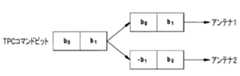
一実施形態において、TPCコマンドビットなどの非パイロットフィールドのビットは、時空間送信ダイバーシティ(STTD)の方法で送信され得る。図7は、TPCコマンドビットの例示的なSTTD符号化を示す。2つ(または2つ以上)のTPCコマンドビットが、STTD符号化され、2つのアンテナ(またはビーム)によって送信される。非パイロットビットの数が奇数であるとき、WTRUは、STTD符号化のためにパイロットビットのうちの1つを符号化する可能性がある。In one embodiment, bits of non-pilot fields, such as TPC command bits, may be transmitted in a space-time transmit diversity (STTD) manner. Figure 7 shows an example STTD encoding of TPC command bits. Two (or more) TPC command bits are STTD encoded and transmitted by two antennas (or beams). When the number of non-pilot bits is odd, the WTRU may encode one of the pilot bits for STTD encoding.
あるいは、WTRUは、第1のDPCCHシーケンスに時空間エンコーダ(space-time encoder)を適用することによって第2のDPCCHのビットシーケンス全体を導出する可能性がある。図8は、DPCCHの時空間符号化のための代替的方法を示す。DPCCH1に関するビットシーケンスは、DPCCH2(すなわち、副DPCCH(S-DPCCH))に関するビットシーケンスを生成するために時空間エンコーダ802によって処理される。第2のDPCCHにマッピングされる時空間エンコーダの出力は、第1のDPCCHに関するビットシーケンスと直交する可能性がある。Alternatively, the WTRU may derive the entire bit sequence of the second DPCCH by applying a space-time encoder to the first DPCCH sequence. FIG. 8 shows an alternative method for space-time coding of the DPCCH. The bit sequence for DPCCH1 is processed by a space-
例えば、Alamouti STTDエンコーダが、直交するDPCCH2シーケンスを生成するために使用され得る。これは、スロット全体にわたってビットの対に対して行われ得る。10シンボルのDPCCHスロットに関して、これは、表3に示されるビットのマッピングを用いることによって実現される可能性があり、「-」記号の演算子は関連するビット値を反転させる。For example, an Alamouti STTD encoder can be used to generate an orthogonal DPCCH2 sequence. This can be done for pairs of bits across the slot. For a 10-symbol DPCCH slot, this can be achieved by using the bit mapping shown in Table 3, where the "-" operator inverts the associated bit value.

あるいは、時空間マッピングは、第1のDPCCHのフィールドのサブセットに適用される可能性がある。Alternatively, the space-time mapping may be applied to a subset of the fields of the first DPCCH.
別の実施形態において、TPCフィールドなどの非パイロットフィールドは、2つのアンテナ/ビームで繰り返し送信される可能性がある。同じビットが、2つのアンテナ/ビームから等しい電力で送信される。図9は、TPCコマンドビットの例示的な繰り返し送信を示す。In another embodiment, non-pilot fields such as the TPC field may be transmitted repeatedly on two antennas/beams. The same bits are transmitted with equal power from the two antennas/beams. Figure 9 shows an exemplary repeated transmission of the TPC command bits.
別の実施形態において、TPCフィールドなどの非パイロットフィールドは、図10に示されるように、第2のDPCCHで間欠送信される可能性がある。図10は、第2のアンテナでのTPCフィールドのビットのDTXを示す。In another embodiment, non-pilot fields such as the TPC field may be transmitted intermittently on the second DPCCH, as shown in FIG. 10, which illustrates DTX of the bits of the TPC field on the second antenna.
構成されるとき、DPCCHのスロットのフォーマット(表2参照)でのTPCフィールドのサイズは、2または4ビットである可能性がある。TPCフィールドは単一のTPCコマンドに関する情報(すなわち、1ビット)を搬送するので、特定のTPCビットパターンが、表4に示されるように各送信電力制御コマンドに関して現在規定されている。When configured, the size of the TPC field in the DPCCH slot format (see Table 2) can be 2 or 4 bits. Since the TPC field carries information about a single TPC command (i.e., 1 bit), a specific TPC bit pattern is currently defined for each transmit power control command as shown in Table 4.

一実施形態において、第2のDPCCHでTPCコマンドを搬送するために使用されるTPCビットパターンは、(例えば、判定指向モード(decision-directed mode)でTPCフィールドを追加のパイロットビットとして用いることによって)NodeBにおける検波およびチャネル推定の信頼性を高めるために修正され得る。第2のDPCCHに関するTPCビットパターンは、第1のDPCCHに関するTPCビットパターンと直交する可能性がある。これは、例えば、それらのビットパターンのTPCビットの半分を反転させることによって実現され得る。表5~7は、第2のDPCCHに関するTPCビットパターンの例を示す。In one embodiment, the TPC bit pattern used to carry the TPC commands on the second DPCCH may be modified to increase the reliability of detection and channel estimation at the NodeB (e.g., by using the TPC field as additional pilot bits in a decision-directed mode). The TPC bit pattern for the second DPCCH may be orthogonal to the TPC bit pattern for the first DPCCH. This may be achieved, for example, by inverting half of the TPC bits of those bit patterns. Tables 5-7 show examples of TPC bit patterns for the second DPCCH.


今度のTPCコマンドの値を計算した後、WTRUは、第1のDPCCHのTPCフィールドに(表4に示された)通常のTPCビットパターンを適用し、第2のDPCCHのTPCフィールドに(例えば、表5~7に示された)対応する(例えば、直交する)TPCビットパターンを適用する可能性がある。After calculating the value of the upcoming TPC command, the WTRU may apply the normal TPC bit pattern (shown in Table 4) to the TPC field of the first DPCCH and the corresponding (e.g., orthogonal) TPC bit pattern (e.g., shown in Tables 5-7) to the TPC field of the second DPCCH.
S-DPCCHは、スロットごとに8パイロットビットを搬送する可能性があり、残りの2ビットは、制御情報のシグナリングのために使用される可能性がある。つまり、各S-DPCCHスロットは、拡散操作の前、8ビットのパイロットフィールドおよび2ビットの非パイロットフィールドを含む可能性がある。S-DPCCHの2ビットの非パイロットフィールドの信頼できる送信を行うために、2ビットの非パイロットフィールドは、DPCCHで適用されるプリコーディングの重みベクトルを用いてプリコーディングされる可能性があり、一方、8ビットのパイロットフィールドは、DPCCHに適用されるプリコーディングの重みベクトルに直交するプリコーディングの重みベクトルを用いてプリコーディングされる可能性がある。The S-DPCCH may carry 8 pilot bits per slot, and the remaining 2 bits may be used for signaling control information. That is, each S-DPCCH slot may contain an 8-bit pilot field and a 2-bit non-pilot field before the spreading operation. To provide a reliable transmission of the 2-bit non-pilot field of the S-DPCCH, the 2-bit non-pilot field may be precoded with a precoding weight vector applied on the DPCCH, while the 8-bit pilot field may be precoded with a precoding weight vector orthogonal to the precoding weight vector applied on the DPCCH.
DPCCHに適用されるべき主プリコーディングの重みベクトルがw1であり、DPCCHの利得係数がβCであり、w1に直交する関連する副プリコーディングの重みベクトルがw2であると定義される。S-DPCCHの非パイロットフィールドは、w1を用いてプリコーディングされる可能性があり、S-DPCCHの非パイロットフィールドの利得係数は、βCに設定される可能性があり、S-DPCCHのパイロットフィールドは、w2を用いてプリコーディングされる可能性があり、S-DPCCHのパイロットフィールドの利得係数は、YβCに設定される可能性がある。あるいは、S-DPCCHの非パイロットフィールドは、w1を用いてプリコーディングされる可能性があり、S-DPCCHの非パイロットフィールドの利得係数は、YβCに設定される可能性があり、S-DPCCHのパイロットフィールドは、w2を用いてプリコーディングされる可能性があり、S-DPCCHのパイロットフィールドの利得計数は、YβCに設定される可能性がある。 A primary precoding weight vector to be applied to the DPCCH is defined as w1 , a gain factor for the DPCCH is βC , and an associated secondary precoding weight vector orthogonal to w1 is defined as w2 . The non-pilot fields of the S-DPCCH may be precoded with w1 , and the gain factor of the non-pilot fields of the S-DPCCH may be set to βC , and the pilot field of the S-DPCCH may be precoded with w2 , and the gain factor of the pilot field of the S-DPCCH may be set toY βC . Alternatively, the non-pilot fields of the S-DPCCH may be precoded with w1 , and the gain factor of the non-pilot fields of the S-DPCCH may be set toY βC , and the pilot field of the S-DPCCH may be precoded with w2 , and the gain factor of the pilot field of the S-DPCCH may be set toY βC .
アップリンクのDPCCH電力制御プリアンブル(power control preamble)が、無線リンクのデータ送信の初期化のために使用される。電力制御プリアンブルの長さNpcpは、上位レイヤによってシグナリングされる。2つの送信アンテナを有するWTRUに関しては、Npcp>0であるとき、アップリンクのDPCCH電力制御プリアンブルは、以下の方法のうちのいずれかで送信され得る。 The uplink DPCCH power control preamble is used for initialization of data transmission on the radio link. The length of the power control preamble, Npcp , is signaled by higher layers. For a WTRU with two transmit antennas, when Npcp > 0, the uplink DPCCH power control preamble may be transmitted in any of the following ways:
一実施形態において、アップリンクのDPCCH電力制御プリアンブルは、各アンテナで1DPCCHずつ、両方のアンテナで送信される可能性がある。普遍性を失うことなく、第1のDPCCHは、レガシーのパイロットビットパターンを用いてアンテナ1で送信される可能性があり、第2のDPCCHは、上で開示されたように、第1のDPCCHで使用されるパイロットビットパターンに直交し得るパイロットビットパターンを用いてアンテナ2で送信される可能性がある。両方のDPCCHのTFCI(transport format combination index)フィールドは、存在する場合、「0」ビットで満たされる可能性がある。FBIビットおよびTPCビットなどのその他の非パイロットフィールドは、上で開示された実施形態を用いて送信され得る。In one embodiment, the uplink DPCCH power control preamble may be transmitted on both antennas, one DPCCH on each antenna. Without loss of generality, the first DPCCH may be transmitted on
別の実施形態においては、第1のDPCCH電力制御プリアンブルが送信され得るが、第2のDPCCH電力制御プリアンブルは間欠送信される可能性がある。In another embodiment, the first DPCCH power control preamble may be transmitted, but the second DPCCH power control preamble may be transmitted intermittently.
別の実施形態においては、第1のDPCCH電力制御プリアンブルが送信される可能性があり、第2のDPCCH電力制御プリアンブルが、第1の事前に定義された期間(例えば、プリアンブルの長さの全体の長さもしくは半分の長さ、または何らかのその他の定義された期間)の間、間欠送信される可能性があり、次の期間の間は、第2のDPCCH電力制御プリアンブルが送信され、第1のDPCCH電力制御プリアンブルが間欠送信される可能性がある(またはあるいは、両方のDPCCH電力制御プリアンブルが送信される可能性がある)。事前に定義された期間は、仕様で定義されるか、または上位レイヤのシグナリングによって定義される可能性がある。In another embodiment, a first DPCCH power control preamble may be transmitted and a second DPCCH power control preamble may be transmitted intermittently for a first predefined period (e.g., the entire length or half the length of the preamble, or some other defined period), and during a next period, the second DPCCH power control preamble may be transmitted and the first DPCCH power control preamble may be transmitted intermittently (or alternatively, both DPCCH power control preambles may be transmitted). The predefined period may be defined in the specification or by higher layer signaling.
アップリンクの電力制御における第1のおよび第2のDPCCHの電力の調整のための実施形態が、以降で開示される。WTRUとNodeBの間で確立された1つまたは複数のアップリンクの電力制御ループが存在する可能性がある。Embodiments for adjusting the power of the first and second DPCCHs in uplink power control are disclosed hereafter. There may be one or more uplink power control loops established between the WTRU and the NodeB.
1つの電力制御ループが使用される場合、UL DPCCHの送信電力を制御するために、1つのTPCコマンドがWTRUによって受信される。TPCコマンド組み合わせ期間(TPC command combining period)に受信されたTPCコマンドに基づいて、WTRUは、適切な電力制御アルゴリズムによって単一のTPCコマンド、TPC_cmdを導出し、ΔDPCCH(dB)によって表される、DPCCHの電力の前の値に対するDPCCHの電力の変化を導出し、
ΔDPCCH=ΔTPC×TPC_cmd 式(1)
によって与えられるΔDPCCH(dB)のステップを用いてアップリンクのDPCCHの送信電力を調整する。 When one power control loop is used, one TPC command is received by the WTRU to control the transmit power of the UL DPCCH. Based on the TPC commands received in a TPC command combining period, the WTRU derives a single TPC command, TPC_cmd, by an appropriate power control algorithm and derives the change in the power of the DPCCH relative to its previous value, represented by ΔDPCCH (dB);
ΔDPCCH = ΔTPC × TPC_cmd Formula (1)
The transmit power of the uplink DPCCH is adjusted with a step of ΔDPCCH (dB) given by:
アップリンクのDPCCH電力制御プリアンブルの間に、WTRUは、ΔDPCCH(dB)によって表される、DPCCHの電力の前の値に対するDPCCHの電力の変化を導出し、式(1)のΔDPCCH(dB)のステップを用いてアップリンクのDPCCH電力制御プリアンブルの総送信電力を調整する可能性がある。アップリンクのDPCCHの送信電力の導出された変化、ΔDPCCHに基づいて、WTRUは、以下の実施形態のうちの1つまたは任意の組み合わせによって、組み合わされたTPCコマンドに基づいて、第1のDPCCHおよび(第2のDPCCHが構成される場合は)第2のDPCCHの送信電力を制御する可能性がある。 During the uplink DPCCH power control preamble, the WTRU may derive a change in the power of the DPCCH relative to a previous value of the power of the DPCCH, represented by ΔDPCCH (dB), and adjust the total transmit power of the uplink DPCCH power control preamble using the step of ΔDPCCH (dB) in equation (1). Based on the derived change in the transmit power of the uplink DPCCH, ΔDPCCH , the WTRU may control the transmit power of the first DPCCH and (if a second DPCCH is configured) the second DPCCH based on the combined TPC command according to one or any combination of the following embodiments.
一実施形態において、WTRUは、以下のように2つのパイロットチャネルに電力を等しく割り当てる可能性がある。
ΔDPCCH1=ΔDPCCH2=(ΔDPCCH)/2 式(2) In one embodiment, the WTRU may allocate power equally to the two pilot channels as follows:
ΔDPCCH1 = ΔDPCCH2 = (ΔDPCCH )/2 Formula (2)
別の実施形態において、WTRUは、以下のように、第1のおよび第2のDPCCHでそれぞれ使用されるパイロットの長さに反比例する電力を割り当てる可能性がある。
ΔDPCCH=ΔDPCCH1+ΔDPCCH2、および 式(3)
ΔDPCCH2=(Npilot1/Npilot2)×(ΔDPCCH1) 式(4) In another embodiment, the WTRU may allocate power inversely proportional to the length of the pilots used in the first and second DPCCHs, respectively, as follows:
ΔDPCCH =ΔDPCCH1 +ΔDPCCH2 , and Equation (3)
ΔDPCCH2 = (Npilot1 /Npilot2 ) × (ΔDPCCH1 ) Equation (4)
別の実施形態においては、ULの同期が達せられる前に、WTRUは、ULの同期の速度を上げるために、第2のDPCCHの電力を下げながら第1のDPCCHの電力を上げるようにして2つのパイロットチャネルの間に調整可能なDPCCHの合計電力を割り当てる可能性がある(すなわち、ΔDPCCH2はΔDPCCH1よりも小さい可能性がある)。ΔDPCCH2は、負である可能性がある。これは、NodeBにおけるULの同期プリミティブ(synchronization primitive)が、第1のDPCCHの品質または巡回冗長検査(CRC)検査に基づく場合に有利である。 In another embodiment, before UL synchronization is achieved, the WTRU may allocate adjustable DPCCH total power between the two pilot channels, increasing the power of the first DPCCH while decreasing the power of the second DPCCH, to speed up UL synchronization (i.e., ΔDPCCH2 may be smaller than ΔDPCCH1 ). ΔDPCCH2 may be negative. This is advantageous if the UL synchronization primitive at the NodeB is based on the quality of the first DPCCH or a Cyclic Redundancy Check (CRC) check.
別の実施形態において、WTRUは、ΔDPCCHおよび(ΔDPCCH+ΔWTRU_sec_dpcch_backoff)のステップを用いて第1のおよび第2のUL DPCCHの送信電力を調整する可能性があり、ここで、ΔWTRU_sec_dpcch_backoffは、第1のDPCCHに対する第2のDPCCHの電力オフセットを表し、ΔWTRU_sec_dpcch_backoffは、上位レイヤによって設定されるか、または仕様によって事前に定義されるか、または(例えば、HS-SCCH(high speed shared control channel)命令を介して)NodeBによって、もしくはDLの制御チャネルのいずれかもしくは何らかの上位レイヤのシグナリングによってWTRUに動的にシグナリングされる可能性がある、 In another embodiment, the WTRU may adjust the transmit power of the first and second UL DPCCHs using a step of ΔDPCCH and (ΔDPCCH + ΔWTRU_sec_dpcch_backoff ), where ΔWTRU_sec_dpcch_backoff represents a power offset of the second DPCCH relative to the first DPCCH, and ΔWTRU_sec_dpcch_backoff may be configured by higher layers, predefined by a specification, or dynamically signaled to the WTRU by the Node B (e.g., via a high speed shared control channel (HS-SCCH) command) or by any of the DL control channels or any higher layer signaling.
別の実施形態において、WTRUは、第1のおよび第2のDPCCHの送信電力を調整するときにアンテナの不均衡を考慮に入れることによって上述の実施形態のいずれかを使用する可能性がある。例えば、第1の実施形態(すなわち、電力の変更を等しく割り当てる)が使用されると仮定すると、2つのアンテナの間の電力の不均衡(power imbalance)(PI)を考慮に入れることによって、DPCCHの電力オフセットは、以下のように計算され得る。
ΔDPCCH1=(ΔDPCCH+PI)/2、および 式(5)
ΔDPCCH2=(ΔDPCCH-PI)/2 式(6)
この実施形態は、2つのDPCCHがプリコーディングされない場合に有用である可能性がある。 In another embodiment, the WTRU may use any of the above embodiments by taking into account the antenna imbalance when adjusting the transmit power of the first and second DPCCHs. For example, assuming the first embodiment (i.e., allocating the power change equally) is used, by taking into account the power imbalance (PI) between the two antennas, the power offset of the DPCCH may be calculated as follows:
ΔDPCCH1 = (ΔDPCCH + PI) / 2, and Equation (5)
ΔDPCCH2 = (ΔDPCCH - PI)/2 Formula (6)
This embodiment may be useful if the two DPCCHs are not precoded.
2つのULの電力制御ループが使用される場合、UL DPCCHの送信電力を個々に制御するために、2つのTPCコマンドがWTRUによって受信される。通常のアップリンクの電力制御の規則が、第2のDPCCHのために再利用される可能性がある。When two UL power control loops are used, two TPC commands are received by the WTRU to individually control the transmit power of the UL DPCCH. The normal uplink power control rules may be reused for the second DPCCH.
UL TxダイバーシティがDPCCHのために使用されるとき、レガシーのDPCCHのために使用される上位レイヤからシグナリングされる初期DPCCH電力を第1のDPCCHのための初期送信電力と第2のDPCCHのための初期送信電力とに分けるために、上述の実施形態のいずれかが使用され得る。When UL Tx diversity is used for the DPCCH, any of the above-described embodiments may be used to split the initial DPCCH power signaled from a higher layer used for the legacy DPCCH into an initial transmit power for the first DPCCH and an initial transmit power for the second DPCCH.
例えば、PRACH(physical random access channel)の2つのプリアンブルのために電力ランプステップ(power ramp step)、ΔP0を分割するため、または最後に送信されたプリアンブルの電力に対するランダムアクセスメッセージの制御部の送信電力オフセット、すなわち、Pp-m[dB]を分割するために、第1のおよび第2のDPCCHまたはDPCCH電力制御プリアンブルの送信電力を調整するための上述の実施形態のいずれかが、UL Txダイバーシティを使用するPRACHに適用され得る。 For example, any of the above-mentioned embodiments for adjusting the transmit power of the first and second DPCCH or DPCCH power control preambles to divide the power ramp step, ΔP0 , for the two preambles of a physical random access channel (PRACH), or to divide the transmit power offset of the control part of the random access message relative to the power of the last transmitted preamble, i.e., Ppm [dB], may be applied to a PRACH using UL Tx diversity.
WTRUがNodeBに2つのDPCCHを送信するとき、アップリンクの同期プリミティブは、第1のDPCCHと第2のDPCCHの両方の品質に基づいて推定され得る。あるいは、アップリンクの同期プリミティブは、第1のDPCCHの品質に基づいて推定され得る。あるいは、アップリンクの同期プリミティブは、フィルタリングされた第1のおよび第2のDPCCHの品質に基づいて推定され得る。When the WTRU transmits two DPCCHs to the NodeB, the uplink synchronization primitive may be estimated based on the quality of both the first DPCCH and the second DPCCH. Alternatively, the uplink synchronization primitive may be estimated based on the quality of the first DPCCH. Alternatively, the uplink synchronization primitive may be estimated based on the quality of the filtered first and second DPCCHs.
受信機におけるプリコーディングに基づくMIMO送信および時空間送信ダイバーシティ(STTD)/時空間ブロック符号化(space time block coding)(STBC)などのMIMO送信スキームのために、異なる送信アンテナからのチャネルは、シンボル検出の前に知られているかまたは推定される必要がある。これは、送信機と受信機の両方で知られているパイロットビットを用いて行われ得る。複数の送信アンテナに関して、2つ以上のアンテナから送信されるパイロットシーケンスは、互いに直交する可能性がある。For MIMO transmission schemes such as MIMO transmission and space-time transmit diversity (STTD)/space time block coding (STBC) based on precoding at the receiver, the channels from different transmit antennas need to be known or estimated before symbol detection. This can be done using pilot bits that are known at both the transmitter and the receiver. For multiple transmit antennas, the pilot sequences transmitted from two or more antennas may be orthogonal to each other.
表8および9は、パイロットビットの異なる長さNpilotに対する通常のDPCCHのパイロットビットパターンを示す。パイロットビットパターンのfx列(x=1...4)は、フレームの同期を確認するために使用され得るフレーム同期ワード(FSW)として定義される。FSW以外のパイロットビットパターンの値は「1」である。所与の長さNpilotを有するスロットのパイロットビットパターンに関して、NfはFSWの数であり、Nrは非FSWの数である。表8および9においては、f1...f4によって識別される4つの異なるFSWシーケンスが存在する。 Tables 8 and 9 show the pilot bit patterns of the normal DPCCH for different pilot bit lengths Npilot . The fx columns (x=1...4) of the pilot bit pattern are defined as Frame Synchronization Words (FSWs) that can be used to verify frame synchronization. The value of the pilot bit pattern other than the FSW is "1". For the pilot bit pattern of a slot with a given length Npilot , Nf is the number of FSWs and Nr is the number of non-FSWs. In Tables 8 and 9, there are four different FSW sequences identified by f1 ...f4 .


多次元チャネル行列(multi-dimensional channel matrix)のチャネル推定のための第2のアンテナに関する新しいパイロットビットシーケンスの実施形態が、以降で開示される。新しいパイロットパターンは、通常のパイロットパターンを使用し、それらの通常のパイロットパターンを第2のアンテナ/ビームで使用されるべき新しい1組の(直交性を有する)パイロットパターンに変換して設計され得る。このアプローチは、FSWの相関性を維持する新しい1組のパイロットシーケンスを導出するために使用され得る。An embodiment of a new pilot bit sequence for the second antenna for channel estimation of a multi-dimensional channel matrix is disclosed hereafter. The new pilot patterns can be designed by using the normal pilot patterns and transforming them into a new set of (orthogonal) pilot patterns to be used on the second antenna/beam. This approach can be used to derive a new set of pilot sequences that maintains the correlation of the FSW.
パイロットビットの数が偶数であるとき、直交性は、所与のスロットの1つの単一のパイロットフィールド内で実現され得る。FSWベクトルと非FSWベクトルが編成される順序は、通常のパイロットフィールドのように維持され得る。偶数個のパイロットビットに関する直交シーケンスを得るために、FSWベクトルの(パイロットシーケンスの長さの半分に対応する)サブセットが反転される可能性がある。表10は、このようにして生成された例示的なパイロットシーケンスを示す。When the number of pilot bits is even, orthogonality can be achieved within one single pilot field of a given slot. The order in which the FSW and non-FSW vectors are organized can be maintained as in a normal pilot field. To obtain an orthogonal sequence for an even number of pilot bits, a subset of the FSW vectors (corresponding to half the length of the pilot sequence) can be reversed. Table 10 shows an exemplary pilot sequence generated in this way.

別の実施形態においては、非FSWビットが反転される可能性がある。Npilot=4およびNpilot=8に関しては、パターンのシーケンスのちょうど半分が非FSWビットからなるので、この実施形態は、すべての非FSWビットを(1から0に)反転させることによって実施され得る。Npilot=6に関しては、(各スロットに関して)6ビット中の2ビットが非FSWビットである。したがって、この場合、1つのFSWビットが、直交性を保つために反転され得る。結果として得られる例示的なビットパターンが、表11に示される。 In another embodiment, the non-FSW bits may be inverted. For Npilot =4 and Npilot =8, exactly half of the sequence of patterns consists of non-FSW bits, so this embodiment may be implemented by inverting all non-FSW bits (from 1 to 0). For Npilot =6, 2 out of 6 bits (for each slot) are non-FSW bits. Therefore, in this case, one FSW bit may be inverted to preserve orthogonality. The resulting exemplary bit patterns are shown in Table 11.

WTRUおよびNodeBは、構成に応じて適切なビットを単純に反転させる可能性がある。これは、シーケンスが2値シフトレジスタ回路を用いて生成される場合と、シーケンスがテーブルでハードコードされる場合(この場合、否定回路が適切に実装されるならば、単一のテーブルが必要とされる可能性がある)との両方で行われ得る。The WTRU and NodeB may simply flip the appropriate bits depending on the configuration. This may be done both if the sequence is generated using a binary shift register circuit or if the sequence is hard-coded in a table (in which case a single table may be required if the negation circuitry is properly implemented).
偶数のNpilotに関しては、直交性がタイムスロットごとに維持され得るが、Npilotが奇数であるときは、直交性を崩す相関で残される1ビットの残余が存在する。奇数個のパイロットシンボルに関して直交性を維持するために、直交性は、1スロットの代わりに2スロットにわたって適用される可能性がある。 For an even number of Npilots , orthogonality can be maintained per time slot, but when Npilot is odd, there is a one bit residual left over correlation that breaks the orthogonality. To maintain orthogonality for an odd number of pilot symbols, the orthogonality can be applied over two slots instead of one slot.
一実施形態においては、2つのパイロットパターンが、第2のパイロットに関して生成される可能性がある(パターンAおよびB)。WTRUは、時間的に交互に入れ替わるパターンAおよびBを送信する可能性がある。あるいは、WTRUは、偶数スロットの間はパターンAを送信し、無線フレームの奇数スロットの間はパターンBを送信する可能性がある。FSWビットを反転させることによって生成される、奇数個のパイロットシンボルに関する例示的なパイロットパターンが、表12および13に示される。In one embodiment, two pilot patterns may be generated for the second pilot (patterns A and B). The WTRU may transmit patterns A and B that alternate in time. Alternatively, the WTRU may transmit pattern A during even slots and pattern B during odd slots of the radio frame. Exemplary pilot patterns for an odd number of pilot symbols generated by flipping the FSW bit are shown in Tables 12 and 13.


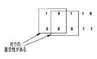
別の実施形態においては、直交性の要件が、2つのパイロットパターン内の連続的に対にされたビットのいずれもが直交することを要求する対による直交性(pair-wise orthogonality)の概念を導入することによって緩められる可能性がある。図11は、対による直交性を有するビットストリームの例を示す。In another embodiment, the orthogonality requirement may be relaxed by introducing the concept of pair-wise orthogonality, which requires that any consecutively paired bits in two pilot patterns are orthogonal. Figure 11 shows an example of a bit stream with pair-wise orthogonality.
第1のアンテナに送られる主パイロットパターンからのビットをCp1(n),n=0,1,2,...,Npilot-1と表す。第2のアンテナに送られる副パイロットビットパターンに関して、対による直交性は、以下のように主パイロットパターンのビットを1つおきに反転させることによって実現され得る。 Let the bits from the primary pilot pattern sent to the first antenna be denoted as Cp1 (n), n = 0, 1, 2, ..., Npilot - 1. For the secondary pilot bit pattern sent to the second antenna, pairwise orthogonality may be achieved by inverting every other bit of the primary pilot pattern as follows:

ここで、Here,

は、ビットを反転させる操作を表す。このプロセスが、すべてのスロットのパイロットビットパターンに対して繰り返される可能性がある。represents the operation of inverting a bit. This process may be repeated for the pilot bit patterns of all slots.
このようにして副パイロットパターンを設計することによって、新しいパイロットパターンのFSWのビットの位置は、通常のパイロットパターンのFSWのビットの位置と同じである可能性があり、新しいパイロットビットパターンのFSWの自己相関は、通常のパイロットビットパターンのFSWの自己相関以上に良好である可能性があり、新しいパイロットビットパターンのFSWと非FSWおよびその他のFSWとの間の相互相関は、レガシーのパイロットパターンのFSWと非FSWおよびその他のFSWとの間の相互相関以上に良好である可能性がある。By designing the secondary pilot pattern in this manner, the bit positions of the FSW of the new pilot pattern may be the same as the bit positions of the FSW of the normal pilot pattern, the autocorrelation of the FSW of the new pilot bit pattern may be better than the autocorrelation of the FSW of the normal pilot bit pattern, and the cross-correlation between the FSW of the new pilot bit pattern and the non-FSW and other FSW may be better than the cross-correlation between the FSW of the new pilot bit pattern and the non-FSW and other FSW of the legacy pilot pattern.
同じ原理が、パイロットビットの数が偶数である場合に適用され得る。偶数のパイロットビットと奇数のパイロットビットの両方の組み合わせで、表14は、Npilot=3、4、5、および6に対する例示的な副パイロットパターンを示し、表15は、Npilot=7および8に対する例示的な副パイロットパターンを示す。 The same principle can be applied when the number of pilot bits is even. For both combinations of even and odd numbers of pilot bits, Table 14 shows exemplary secondary pilot patterns for Npilot = 3, 4, 5, and 6, and Table 15 shows exemplary secondary pilot patterns for Npilot = 7 and 8.


別の実施形態において、副パイロットパターンは、対による直交性のために異なる反転パターン(例えば、偶数ビットを反転させる)を用いて生成され得る。表16および17は、このように例示的な副パイロットビットパターンを示す。In another embodiment, the secondary pilot patterns may be generated using different inversion patterns (e.g., inverting even bits) for pairwise orthogonality. Tables 16 and 17 thus show exemplary secondary pilot bit patterns.


別の実施形態においては、対による直交性が、無線フレーム全体の範囲でスロットの境界をまたがって維持される可能性がある。例えば、奇数ビットを判定させるNpilot=3に関して、副パイロットビットパターンは、 In another embodiment, pairwise orthogonality may be maintained across slot boundaries throughout the entire radio frame. For example, for Npilot =3, which determines odd bits, the secondary pilot bit pattern may be:

のように生成される可能性があり、ここで、上付き文字は、スロット番号を表す。例示的な結果として得られるパイロットビットパターンが、表18および19に示される。where the superscript represents the slot number. Exemplary resulting pilot bit patterns are shown in Tables 18 and 19.


あるいは、代わりに偶数ビットが反転され得る。例えば、Npilot=3のとき、パイロットビットパターンの別の組が、以下のように生成され得る。 Alternatively, the even bits can be inverted instead. For example, when Npilot =3, another set of pilot bit patterns can be generated as follows:

例示的なビットパターンが、表20および21に示される。Exemplary bit patterns are shown in Tables 20 and 21.


対による直交性は、より大きな直交するブロックのサイズを有するようにさらに広げられ得る。L個の連続するビットのあらゆるブロックが、主パイロットシーケンスと副パイロットシーケンスの間で直交する可能性があり、ここで、Lは、任意の偶数である可能性がある。図12は、L=4である2値ストリームの例を示す。The pairwise orthogonality can be further extended to have larger orthogonal block sizes. Any block of L consecutive bits can be orthogonal between the primary and secondary pilot sequences, where L can be any even number. Figure 12 shows an example of a binary stream with L=4.
例えば、L=4に関して、副パイロットビットパターンは、以下のように生成され得る。For example, for L=4, the secondary pilot bit pattern can be generated as follows:

ここで、mod(x,4)は、変数xに対して実行されるモジュロ4演算を示す。Here, mod(x,4) denotes the
異なる反転パターンが使用される可能性があり、直交性がスロットの境界をまたがって維持される可能性がある。Different inversion patterns may be used and orthogonality may be maintained across slot boundaries.
対による直交性を有するパイロットを用いたチャネル推定が、以降で開示される。普遍性を失うことなく、2x1のアンテナ構成を有するアップリンクのTXダイバーシティシステムが、Npilotが奇数であるときの上で開示されたパイロットビットパターンからのチャネル推定を示すために使用される。 Channel estimation using pairwise orthogonal pilots is disclosed hereafter. Without loss of generality, an uplink TX diversity system with a 2x1 antenna configuration is used to demonstrate channel estimation from the pilot bit patterns disclosed above when Npilot is odd.
図13は、アップリンクのTXダイバーシティシステムにおける例示的なパイロットの送信を示す。主パイロットおよび副パイロットは、送信のために2つのアンテナ1308に送られる前に、別々に変調マッパ1302によってシンボル(例えば、2位相偏移変調(BPSK)シンボル)にマッピングされ、拡散ブロック1304によって拡散され、スクランブリング符号を用いてスクランブルブロック1306によってスクランブルされる。変調マッピング操作において、スロットのパイロットビットが、BPSKシンボルにマッピングされ得る。Figure 13 shows an example pilot transmission in an uplink TX diversity system. The primary and secondary pilots are separately mapped to symbols (e.g., binary phase shift keying (BPSK) symbols) by
対による直交性を用いて、副パイロットシンボルは、
Cp2(n)=(-1)nCp1(n) 式(9)
と表され得る。 Using pairwise orthogonality, the secondary pilot symbols are
Cp2 (n) = (-1)n Cp1 (n) Equation (9)
It can be expressed as:
受信機側では、受信された信号が、デスクランブルブロック1322、RAKE受信機1324、および逆拡散ブロック1326によって処理される。On the receiver side, the received signal is processed by the
TXチェーンおよびRXチェーンで処理を連結すると、デスプレッダ(despreader)の出力の信号は、以下のように記述され得る。By concatenating the processing in the TX and RX chains, the signal at the output of the despreader can be described as follows:
y(n)=h1(n)Cp1(n)+h2(n)Cp2(n)+n(n)=h1(n)Cp1(n)+h2(n)(-1)nCp1(n)+n(n) 式(10)
ここで、h1(n)およびh2(n)は、それぞれ、アンテナ1および2の伝播経路に関する等価なチャネル状態情報(CSI)であり、n(n)は雑音項である。 y(n)=h1 (n)Cp1 (n)+h2 (n)Cp2 (n)+n(n)=h1 (n)Cp1 (n)+h2 (n)(-1)n Cp1 (n)+n(n) Formula (10)
where h1 (n) and h2 (n) are the equivalent channel state information (CSI) for the propagation paths of
奇数のNpilotに関しては、すべてのシンボルを利用するために、元のパイロットシンボルとの相関を取るときに2組の平均、すなわち、0からNpilot-2までの範囲のシンボルにわたる平均と、1からNpilot-1までのもう1つの平均が実行され得る。チャネル推定は、以下の対による組み合わせから得られる可能性がある。 For an odd number of Npilots , in order to utilize all symbols, two sets of averages may be performed when correlating with the original pilot symbols: one over symbols ranging from 0 to Npilot −2, and another average from 1 to Npilot −1. A channel estimate may be obtained from the following pairwise combinations:

ここで、h1(n)はh2(n)から実質的に分離され、推定は不偏(unbiased)である。Here, h1 (n) is substantially separated from h2 (n) and the estimate is unbiased.
同様に、h2(n)に関して、 Similarly, forh2 (n),

2x2MIMOシステムに関して、チャネル応答h11(n)、h12(n)、h21(n)、およびh22(n)を推定するために、2つの受信アンテナから受信された信号のそれぞれに同様の操作が適用され得る。 For a 2x2 MIMO system, similar operations may be applied to each of the signals received from the two receive antennas to estimate the channel responsesh11 (n),h12 (n),h21 (n), andh22 (n).
異なるチャネライゼーション符号を用いる副パイロットチャネル(例えば、S-DPCCH)に関するパイロットの設計のための実施形態が、以降で開示される。Embodiments for designing pilots for a secondary pilot channel (e.g., S-DPCCH) using different channelization codes are disclosed below.
S-DPCCHが主DPCCH(P-DPCCH)とは異なるチャネライゼーション符号にマッピングされるとき、S-DPCCHのパイロットシーケンスは、P-DPCCHのパイロットシーケンスと直交していない可能性がある。S-DPCCHの品質がNodeBの受信機で保証されない可能性があるので、パイロットシンボルのみがS-DPCCHで搬送され得る。そのような場合、S-DPCCHは、(256の拡散率(SF)を仮定して)DPCCHのスロットのフォーマットに関係なく10個のパイロットシンボルを搬送する可能性がある。When the S-DPCCH is mapped to a different channelization code than the primary DPCCH (P-DPCCH), the pilot sequence of the S-DPCCH may not be orthogonal to the pilot sequence of the P-DPCCH. Since the quality of the S-DPCCH may not be guaranteed at the NodeB receiver, only pilot symbols may be carried on the S-DPCCH. In such a case, the S-DPCCH may carry 10 pilot symbols (assuming a spreading factor (SF) of 256) regardless of the slot format of the DPCCH.
10個のシンボルのパイロットシーケンスは現在の仕様で定義されていないので、新しい10シンボル長のパイロットシーケンスが、S-DPCCHのために定義される必要がある。Since a pilot sequence of 10 symbols is not defined in the current specification, a new pilot sequence of 10 symbols length needs to be defined for S-DPCCH.
一実施形態においては、表9の8個のシンボルの通常のパイロットシーケンスが、2つの非FSWシンボルを追加することによって2シンボル分拡張される可能性がある。2つの非FSWシンボルは、任意の位置に置かれる可能性がある。例えば、2つの追加的な非FSWシンボルは、表22に示されるように、シーケンスの両端に追加される可能性がある。あるいは、2つの追加的な非FSWシンボルは、表23に示されるように、シーケンスの最後に追加される可能性がある。あるいは、2つの追加的な非FSWシンボルは、表24に示されるように、シーケンスの真ん中に追加される可能性がある。In one embodiment, the normal pilot sequence of 8 symbols in Table 9 may be extended by 2 symbols by adding two non-FSW symbols. The two non-FSW symbols may be placed in any position. For example, two additional non-FSW symbols may be added at both ends of the sequence as shown in Table 22. Alternatively, two additional non-FSW symbols may be added at the end of the sequence as shown in Table 23. Alternatively, two additional non-FSW symbols may be added in the middle of the sequence as shown in Table 24.


別の実施形態において、S-DPCCHのパイロットシーケンスは、フレーム同期ワードを利用しない可能性があり、すべて1またはすべて0の単純なシーケンスが代わりに使用される可能性があり、フレーム内のスロット間で一定に保たれる可能性がある。S-DPCCHの受信されるSNRは、インナーループ電力制御(inner loop power control)(ILPC)によって直接制御されない可能性があり、したがって、NodeBは、その中のFSW情報を同期の目的で利用しない可能性がある。In another embodiment, the pilot sequence of the S-DPCCH may not utilize a frame synchronization word; a simple sequence of all ones or all zeros may be used instead and may be kept constant between slots within a frame. The received SNR of the S-DPCCH may not be directly controlled by inner loop power control (ILPC), and therefore the NodeB may not utilize the FSW information therein for synchronization purposes.
探索を目的として第2のパイロットを使用するための実施形態が、以降で開示される。An embodiment for using a second pilot for search purposes is disclosed below.
NodeBにおけるデータの復調およびプリコーディングの重みの選択は、チャネル推定に異なる要件を課す可能性がある。2つのパイロットは、単一のデータストリームの送信の場合には異なる目的に資するように構成され得る。主DPCCHで搬送される主パイロットが、データを復調するために高品質のチャネル推定を得るために設計される可能性がある一方、副DPCCHで搬送されるパイロットは、例えば、最適なプリコーディングの重みの選択のために無線チャネルの状態を探索するために設計される可能性がある。The demodulation of data and the selection of precoding weights at the NodeB may impose different requirements on the channel estimation. The two pilots may be configured to serve different purposes in the case of a single data stream transmission. The primary pilot carried on the primary DPCCH may be designed to obtain a high quality channel estimation for demodulating the data, while the pilot carried on the secondary DPCCH may be designed, for example, to explore the radio channel conditions for the selection of optimal precoding weights.
図14は、探索パイロットの利用を示す。送信機1410において、主DPCCH(およびその他のチャネル)が、Txチェーン1412によって処理される。主DPCCH(およびその他のチャネル)ならびに探索パイロットの利得が、受信機1450の電力制御ブロック1460からのTPCコマンドに基づいて制御される。主DPCCH(およびその他のチャネル)および探索パイロットは、それぞれ、プリコーディングユニット1414、1416によってプリコーディングされ、アンテナ1420を介して送信され得る。受信機1450のチャネル推定ブロック1452が、データの復調のために主パイロットを用いてチャネル推定を実行し、プリコーディングの重みの選択のために探索パイロットを用いてチャネル推定を実行する。受信機1450の重み選択機能1454が、最適な重みベクトルを選択し、送信機1410にフィードバックを送信する。主DPCCHは、探索パイロットに基づいて得られるチャネル状態情報にしたがって受信機によって決定される、ビームフォーミング制御機能1418から出力される最適なプリコーディングの重みWoptによってプリコーディングされる。受信機は、SIR推定ブロック1456によって推定されたSIRの推定値に基づいてTPCコマンドを決定し、電力制御ブロック1460が、そのTPCコマンドを送信機1410に送信し、それによって送信機1410における利得を制御する。探索パイロットは、プリコーディングのコードブック内の重みのすべてまたはサブセットの中の異なるプリコーディングの重み(またはベクトル)で時間的に代わる代わる送信され得る。14 illustrates the use of searcher pilots. In the
図14に示されたビームフォーミング制御機能1418は、探索パイロットを介したプリコーディング操作を制御して最適なプリコーディングの重みを発見することになる。ビームフォーミング制御機能1418は、時分割多重(TDM)の方法を用いてコードブックの利用可能なすべてのプリコーディングベクトルを掃引する事前に定義されたまたはチャネルに応じた探索パターンを提供する。The
限られた数のエントリを有するコードブックが、プリコーディングの重みに関して定義され得る。wi,i=1,2,...,Nがプリコーディングベクトルを表し、Nが利用可能なプリコーディングベクトルの数であるものとする。例えば、w1およびw2は、以下の4つのベクトル値を有する可能性がある。 A codebook with a limited number of entries can be defined for the precoding weights. Letw , i=1, 2,...,N denote the precoding vectors, where N is the number of available precoding vectors. For example,w1 andw2 can have the following four vector values:

アンテナの切り替えは、以下の2つのプリコーディングベクトルが使用される、ビームフォーミングの特別な場合と見なされ得る。Antenna switching can be considered as a special case of beamforming, where the following two precoding vectors are used:

一実施形態において、探索ベクトルの長さは固定である可能性がある。Ti,i=1,2,...,Nを、個々のプリコーディングベクトルがそれぞれ使用される探索状態の長さとして示す。Ti,i=1,2,...,Nは、異なる値に設定されるか、または同一である可能性がある。1つの探索サイクルの総継続時間、Tは、総和T=T1+T2+...TNである。時間間隔の単位は、タイムスロット、送信時間間隔(TTI)、無線フレームなどである可能性がある。探索パターンは、図15に示されるように1つまたは複数の探索サイクルからなる可能性がある。図15は、固定長の探索パターンの例を示す。 In one embodiment, the length of the search vectors may be fixed. Let Ti,i=1,2,...,N be the length of the search states in which an individual precoding vector is used, respectively. Ti,i=1,2,...,N may be set to different values or may be the same. The total duration of one search cycle, T, is the sum T=T1 +T2 +...TN . The unit of time interval may be a time slot, a transmission time interval (TTI), a radio frame, etc. A search pattern may consist of one or more search cycles as shown in Figure 15. Figure 15 shows an example of a fixed length search pattern.
例えば、固定長の探索パターンは、高速なチャネルの状態に関してTTIごとにプリコーディングベクトルを切り替えることによって実施され得る。各探索サイクルは、その探索サイクル独自の継続時間Tのための異なる設定がある可能性がある。For example, a fixed length search pattern can be implemented by switching precoding vectors every TTI with respect to fast channel conditions. Each search cycle can have a different setting for its own duration T.
固定長の探索パターンは、NodeBとWTRUの両方によって制御され得る。探索パターンがWTRUによって制御される場合、探索パターンは自律的に働き、NodeBが事前に決められた探索パターンにしたがってどのプリコーディングベクトルが使用されるのかが分かるように初めにNodeBと同期される必要がある可能性がある。NodeBとWTRUの間の同期のために、WTRUは、L1レベルでNodeBに信号を送り、探索サイクルの始まりを示す可能性がある。あるいは、探索パイロットは、プリコーディングベクトルのそれぞれのために異なる変調パターンをそれぞれ有する可能性がある。あるいは、探索パイロットは、探索サイクルの初めに異なる変調パターンを使用する可能性がある。あるいは、探索パイロットは、探索サイクルの終わりに異なる変調パターンを使用する可能性がある。The fixed length search pattern may be controlled by both the NodeB and the WTRU. If the search pattern is controlled by the WTRU, it may work autonomously and may need to be synchronized with the NodeB initially so that the NodeB knows which precoding vector is to be used according to the predefined search pattern. For synchronization between the NodeB and the WTRU, the WTRU may signal to the NodeB at the L1 level to indicate the beginning of a search cycle. Alternatively, the search pilots may each have a different modulation pattern for each of the precoding vectors. Alternatively, the search pilots may use different modulation patterns at the beginning of a search cycle. Alternatively, the search pilots may use different modulation patterns at the end of a search cycle.
探索パターンがNodeBまたは上位レイヤによって制御される場合、探索パターンは、事前に構成される可能性があり、周期的なスケジュールまたはトリガが、パターンの送信を示すために使用される可能性がある。さらなる制御または柔軟性が望まれる場合、NodeBまたは上位レイヤは、任意の所与の時間にどの重みが送信されるかを制御することができる。これは、使用されるべき特定の重みをシグナリングすることによって、または1組の事前に定置された探索パターンのうちのどの探索パターンが使用され得るかをシグナリングすることによって行われる可能性がある。単一の探索パターンの場合と同様に、送信は、周期的にスケジューリングされるかまたは(要求に応じて)トリガされる可能性がある。If the search pattern is controlled by the NodeB or higher layers, the search pattern may be pre-configured and a periodic schedule or trigger may be used to indicate the transmission of the pattern. If more control or flexibility is desired, the NodeB or higher layers may control which weights are transmitted at any given time. This may be done by signaling the specific weights to be used, or by signaling which search pattern of a set of pre-configured search patterns may be used. As with a single search pattern, the transmission may be scheduled periodically or triggered (on demand).
別の実施形態においては、次の探索状態のためにプリコーディングベクトルを切り替えるべきかどうかを判定する際に、受信機の動作状態が考慮される可能性がある。したがって、1つの特定のプリコーディングベクトルに留まっている継続時間は、必要とされる条件が満たされるか否かに応じて変わり得る可能性がある。切り替えをトリガする要因は、探索パイロットからのチャネル推定の品質、探索パイロットの受信電力、WTRUの速度などを含むがこれらに限定されない。In another embodiment, the operating conditions of the receiver may be taken into consideration when determining whether to switch precoding vectors for the next search state. Thus, the duration of remaining on one particular precoding vector may vary depending on whether required conditions are met. Factors that trigger a switch include, but are not limited to, the quality of the channel estimate from the search pilot, the received power of the search pilot, the speed of the WTRU, etc.
主DPCCHと副DPCCHを分けるために、それらのDPCCHを直交させるために、異なるチャネライゼーション符号が使用され得る。To separate the primary and secondary DPCCHs, different channelization codes may be used to make them orthogonal.
別の実施形態においては、同期を目的とする送信のプリコーディングベクトルを区別するために、探索パイロット(例えば、副DPCCH)で異なる変調パターンが使用される可能性がある。10ビットのパイロットパターンが、表25および26に示すように規定され得る。In another embodiment, different modulation patterns may be used on the search pilots (e.g., secondary DPCCH) to differentiate precoding vectors for transmissions for synchronization purposes. A 10-bit pilot pattern may be defined as shown in Tables 25 and 26.


表26の副探索パイロットの組は、表25の主探索パイロットの組と直交し、探索モードの始まりを特定するために使用され得る。The set of secondary search pilots in Table 26 is orthogonal to the set of primary search pilots in Table 25 and may be used to identify the beginning of a search mode.
別の実施形態において、探索パイロットパターンは、タイムスロットに固有ではない可能性がある。その代わりに、ビットパターンが、異なるプリコーディングベクトルに関連付けられる可能性がある。表27および28は、異なる数のパイロットビットを有する例示的なプリコーディングに固有の探索パイロットパターンを示す。In another embodiment, the search pilot patterns may not be timeslot specific. Instead, bit patterns may be associated with different precoding vectors. Tables 27 and 28 show example precoding-specific search pilot patterns having different numbers of pilot bits.


表28においては、合計で16個のプリコーディングベクトルが考慮される。プリコーディングベクトルの実際の数が16個未満である場合、それらの探索パイロットパターンの任意のサブセットが使用される可能性があり、または1つのプリコーディングベクトルが複数のパイロットパターンに関連付けられる可能性がある。第2のDPCCHの10ビットのすべてが探索パイロットのために使用される場合、表で指定されていないビットフィールドの残りは「1」に設定される可能性がある。In Table 28, a total of 16 precoding vectors are considered. If the actual number of precoding vectors is less than 16, any subset of those search pilot patterns may be used, or one precoding vector may be associated with multiple pilot patterns. If all 10 bits of the second DPCCH are used for search pilots, the rest of the bit fields not specified in the table may be set to "1".
上で開示されたパイロットパターンは探索パイロットに関連して設計されているが、その概念はその他の場合に拡大され得ることを理解されたい。It should be understood that although the pilot patterns disclosed above are designed in conjunction with search pilots, the concept can be extended to other cases.
(例えば、ゆっくりとフェージングするチャネルの状態で)絶えず探索パターンを実行する必要がない場合、探索パイロットは、シグナリングのオーバーヘッドを削減するために無効化される可能性がある。そのような場合、探索パイロットは、間欠送信されるか、または送信を中止される可能性がある。探索パイロットを無効化することおよび有効化することは、新しいHS-SCCH命令またはその他の特別に設計されたダウンリンクのL1シグナリングを介して実施され得る。When there is no need to constantly perform the search pattern (e.g., in slowly fading channel conditions), the search pilots may be disabled to reduce signaling overhead. In such cases, the search pilots may be transmitted intermittently or may cease transmission. Disabling and enabling of the search pilots may be performed via new HS-SCCH orders or other specially designed downlink L1 signaling.
図14の利得制御機能1422は、TPCコマンドを受信し、主DPCCHおよび探索パイロットに対する電力制御を行う。チャネル推定の品質の要件は探索パイロットについてはそれほど高くないので、信号のオーバーヘッドを削減するために、より小さな送信電力が探索パイロットに割り当てられ得る。電力制御を別々に行うことができるように、探索パイロット信号は、物理チャネルの残りによって使用される電力制御ループ内の利得経路(gain path)を通らない可能性がある。その代わりに、探索パイロット信号は、独自の利得制御を有する可能性がある。利得制御機能1422は、2つの利得係数、すなわち、DPCCHおよびそのDPCCHを電力の基準として用いるすべてのその他の物理チャネルの送信電力を制御する利得係数(g)と、探索パイロットに関する利得係数(gprob)とを生成する可能性がある。DPCCHの送信電力は、式(1)の電力制御プロシージャによって調整される。一実施形態において、探索パイロットに関する利得係数は、
gprob(n)=Aprobg(n) 式(15)
によって計算される可能性があり、ここで、Aprobはネットワークによってシグナリングされる電力オフセットであり、nはタイムスロットのインデックスである。 The
gprob (n)=Aprob g(n) Formula (15)
where Aprob is the power offset signaled by the network and n is the time slot index.
この利得係数は、TPCコマンドがタイムスロットごとに受信されるので動的である可能性がある。プリコーディングベクトルの掃引がTDMに基づいて行われる可能性があるので、送信電力がタイムスロットごとに電力制御ループに結びつけられる場合、探索パイロットの送信電力の変動がNodeBの受信機におけるプリコーディングの重みの選択の公平性に影響を与える可能性がある。この問題を緩和するために、利得固定(gain freeze)メカニズムが使用され得る。This gain factor may be dynamic since TPC commands are received every timeslot. Since the sweep of the precoding vector may be done on a TDM basis, variations in the transmit power of the searcher pilot may affect the fairness of the selection of the precoding weights at the NodeB receiver if the transmit power is tied to a power control loop every timeslot. To mitigate this issue, a gain freeze mechanism may be used.
利得固定操作は、gprobがあらゆるタイムスロットごとにgにしたがうのではなく、瞬間n0で指定された値で一定に保たれるように
gprob(n)=Aprobg(n0) 式(16)
によって定式化され得る。n0は、あらゆる探索サイクルの始まりのタイムスロットのスロットインデックスである可能性がある。あるいは、n0は、探索パターンの始まりのタイムスロットのスロットインデックスである可能性がある。あるいは、n0は、あらゆる探索サイクル内のk番目のタイムスロットのスロットインデックスである可能性があり、kは、1からNまでの整数値である可能性がある。あるいは、n0は、あらゆる探索パターン内のk番目のタイムスロットのスロットインデックスである可能性があり、kは、1から探索パターンの終わりまでの整数値である可能性がある。 The gain clamping operation is performed such that gprob is kept constant at a specified value at instant n0 rather than following g at every time slot: gprob (n)=Aprob g(n0 ) Equation (16)
n0 may be formulated by: n 0 may be the slot index of the beginning time slot of every search cycle. Alternatively, n0 may be the slot index of the beginning time slot of a search pattern. Alternatively, n0 may be the slot index of the kth time slot in every search cycle, where k is an integer value from 1 to N. Alternatively, n0 may be the slot index of the kth time slot in every search pattern, where k is an integer value from 1 to the end of the search pattern.
別の実施形態において、gprobは、スロットごとに決まった比でgに結びつけられる可能性がある。電力制御プロシージャによって引き起こされる変動を補償するために、探索パターンの初めから、TPCコマンドが追跡され、記録される可能性がある。調整後の結果が、最適なプリコーディングベクトルの判定に織り込まれる必要がある。 In another embodiment,gprob may be tied to g in a fixed ratio for each slot. The TPC commands may be tracked and recorded from the beginning of the search pattern to compensate for fluctuations caused by the power control procedure. The adjusted results need to be factored into the determination of the optimal precoding vector.

ここで、iはプリコーディングベクトルのインデックスであり、n1は探索サイクルの開始タイムスロットのインデックスであり、n1はプリコーディングベクトルiに関する終了タイムスロットのインデックスである。上記のオフセットが、一定の尺度でdBに換算して計算される。where i is the index of the precoding vector, n1 is the index of the starting timeslot of the search cycle, and n1 is the index of the ending timeslot for precoding vector i. The above offsets are calculated in dB terms on a regular scale.
あるいは、探索パイロットは、gに結びつけられる可能性があり、探索されるプリコーディングされたチャネルの利得は、現在のプリコーディングされたチャネルに対して相対的に測定される可能性がある。重要な測定値は探索パイロットのプリコーディングが現在選択されているプリコーディングよりも良好なチャネルの利得をもたらしているときであるため、NodeBがチャネルの品質を改善することに関心があるのでこれが当てはまる。Alternatively, the searcher pilot could be tied to g and the gain of the searched precoded channel could be measured relative to the current precoded channel. This is the case since the NodeB is interested in improving the quality of the channel, since the measurement of interest is when the precoding of the searcher pilot results in a better channel gain than the currently selected precoding.
コードブックに基づかない探索スキームに関する実施形態が、以降で開示される。図16は、コードブックに基づかない閉ループの送信ビームフォーミングスキームの例を示す。図16においては、DPCCH1ならびにその他のアップリンクチャネル(例えば、E-DPDCH、E-DPCCH、DPDCH、およびHS-DPCCH)が、ベクトル1を用いてプリコーディングブロック1602によってプリコーディングされ、探索パイロットチャネルDPCCH2が、DPCCH1およびその他のアップリンクチャネルに適用されるプリコーディングベクトル1に対する位相の変化を有するベクトル2を用いてプリコーディングブロック1604によってプリコーディングされる。位相の変化は、正の値かまたは負の値かのどちらかである可能性があり、時間によって変わる可能性がある。プリコーディングベクトル1 w1=[w11 w21]Tならびにプリコーディングベクトル2 w2=[w12 w22]Tおよび An embodiment for a non-codebook based search scheme is disclosed hereafter. Figure 16 shows an example of a non-codebook based closed loop transmit beamforming scheme. In Figure 16, DPCCH1 and other uplink channels (e.g., E-DPDCH, E-DPCCH, DPDCH, and HS-DPCCH) are precoded by

を定義し、ここで、Define where:

はクロネッカー積を表す。プリコーディングブロック1602および1604からのプリコーディングされた成分が、コンバイナ(combiner)1606、1608によって足され、対応するアンテナに送られる。represents the Kronecker product. The precoded components from
両方のDPCCHの測定に基づいて、NodeBは、Based on measurements of both DPCCHs, the NodeB:

である可能性がある、DPCCH1に適用されるべき新しいプリコーディングベクトルをWTRUにシグナリングする可能性があり、ここで、w1は、DPCCH1に適用される現在のプリコーディングベクトルを表す。したがって、ダウンリンクで、NodeBは、1ビットの3値シグナリング(DTX、+1、および-1)を用いて、DPCCH1の現在のまたは最も最近使用されたプリコーディングベクトルを基準にしてDPCCH1に適用されるべき次のプリコーディングベクトル(すなわち、位相の変化なし、正の位相の変化、および負の位相の変化)に関してWTRUに示すことができる。位相の変化Δは、準動的に変えられ、上位レイヤを介してNodeBによってWTRUにシグナリングされ得る。In the downlink, the NodeB may signal to the WTRU a new precoding vector to be applied to DPCCH1, which may be
圧縮モードのギャップの間の動作に関する実施形態が、以降で開示される。圧縮モードのギャップは、WTRUの受信機が、周波数内、周波数間、および/または無線アクセス技術(RAT)間の測定を実行するために異なる周波数に再チューニングされる期間である。これらのギャップの間、WTRUは、サービングNodeBから電力制御またはプリコーディングの重みの情報を受信しない可能性がある。Embodiments relating to operation during compressed mode gaps are disclosed below. Compressed mode gaps are periods during which the WTRU's receiver is retuned to a different frequency to perform intra-frequency, inter-frequency, and/or inter-Radio Access Technology (RAT) measurements. During these gaps, the WTRU may not receive power control or precoding weight information from the serving NodeB.
一実施形態において、圧縮モードのギャップの間、WTRUは、再開したときにWTRUが既知の状態にあるようにそのWTRUのプリコーディングの重みを維持する可能性がある。In one embodiment, during gaps in compressed mode, the WTRU may maintain its precoding weights so that when it resumes, the WTRU is in a known state.
第2のパイロットに関してDTX動作が構成されているとき、または特定のDTXパターンが構成されているとき、WTRUは、圧縮モードのギャップから復帰した後しばらく第2のパイロットを送信しない可能性がある。第2のパイロットがないと(あるいはまた、チャネルサウンディングのための手段がないと)、NodeBは、チャネルを適切に推定し、使用する最良のプリコーディングの重みを決定しない可能性がある。そのような場合、WTRUは、最適でないプリコーディングの重みを用いて動作し、性能の一時的な低下につながる可能性がある。そのような性能の悪化を避けるために、圧縮モードのギャップから復帰すると、WTRUは、NodeBが適切なチャネルの測定を行うために十分な期間、第2のパイロット(またはあるいはサウンディングチャネル)を送信する可能性があり、次いで、WTRUは、ダウンリンクの重みの更新情報をリスニングする。When DTX operation is configured for the second pilot or a specific DTX pattern is configured, the WTRU may not transmit the second pilot for some time after returning from a compressed mode gap. Without the second pilot (or alternatively, without the means for channel sounding), the NodeB may not properly estimate the channel and determine the best precoding weights to use. In such a case, the WTRU may operate with suboptimal precoding weights, leading to a temporary degradation in performance. To avoid such a degradation in performance, upon returning from a compressed mode gap, the WTRU may transmit the second pilot (or alternatively the sounding channel) for a period sufficient for the NodeB to make appropriate channel measurements, and then the WTRU listens for updates on the downlink weights.
閉ループ送信ダイバーシティ(CLTD)モードで構成されているWTRUに関しては、圧縮モードが有効化されるとき、第2のDPCCHの導入が原因で、第1のDPCCHのパイロットビットの長さに対する第2のDPCCHのパイロットビットの長さが、アップリンクの送信電力制御に影響を与える。第2のDPCCHのパイロットビットの長さの割り当ておよび対応する電力制御プロシージャに関する実施形態が、以降で開示される。For WTRUs configured in closed loop transmit diversity (CLTD) mode, when compressed mode is enabled, due to the introduction of the second DPCCH, the length of the pilot bits of the second DPCCH relative to the length of the pilot bits of the first DPCCH impacts uplink transmit power control. Embodiments relating to the assignment of the length of the pilot bits of the second DPCCH and the corresponding power control procedures are disclosed below.
一実施形態において、第2のDPCCHは、第1のDPCCHと同じパイロットビットの長さを割り当てられる可能性がある。したがって、アップリンクの第2のDPCCHの圧縮されたフレームおよび圧縮されていないフレームは、スロットごとに異なる数のパイロットビットを有する可能性がある。WTRUは、以下のように、dBの第2のDPCCHの電力オフセットIn one embodiment, the second DPCCH may be assigned the same pilot bit length as the first DPCCH. Thus, the compressed and uncompressed frames of the second DPCCH in the uplink may have a different number of pilot bits per slot. The WTRU may then determine the power offset of the second DPCCH in dB as follows:

を導出することができる。can be derived.

ここで、Here,

は、最も最近送信されたスロットの第2のDPCCHのパイロットビットの数であり、is the number of pilot bits of the second DPCCH in the most recently transmitted slot,

は、現在のスロットの第2のDPCCHのパイロットビットの数である。各スロットにおいて、WTRUは、以下のように第2のDPCCHの送信電力を調整することができる。is the number of pilot bits of the second DPCCH in the current slot. In each slot, the WTRU can adjust the transmit power of the second DPCCH as follows:

この実施形態は、圧縮モードにおいて第1のDPCCHと第2のDPCCHの間の新しい電力比をシグナリングすることを必要としない可能性がある。さらに、電力制御の後のこの電力比は、Δdpcch=Δs-dpcchであるようにほとんどの場合 This embodiment may not require signaling a new power ratio between the first and second DPCCHs in compressed mode. Furthermore, this power ratio after power control is most likely to be Δdpcch = Δs-dpcch.

に保たれる可能性があり、これは、, which means that

およびΔs-dpcchの明示的な計算が行われない可能性があることを意味する。This means that no explicit calculation of Δs-dpcch and Δ s-dpcch may be performed.
別の実施形態において、第2のDPCCHは、圧縮モードの構成と無関係に固定長のパイロットビットを有する可能性がある。例えば、第2のDPCCHは、非圧縮モードと圧縮モードの両方で表2のスロットのフォーマット8を使用する可能性がある。この場合、第2のDPCCHのパイロットビットの数の変化はなく、すなわちIn another embodiment, the second DPCCH may have a fixed length of pilot bits regardless of the compressed mode configuration. For example, the second DPCCH may use slot format 8 of Table 2 in both uncompressed and compressed modes. In this case, there is no change in the number of pilot bits of the second DPCCH, i.e.

であり、したがって、Δs-dpcch=ΔTPC×TPC_cmdである。一方、TPC_cmdは、パイロットビットの長さが非圧縮モードと圧縮モードの間で変わる可能性がある第1のDPCCHに基づいて生成される可能性がある。圧縮モードでTxダイバーシティのないWTRUのための通常の電力制御を再利用するために、WTRUが圧縮モードで動作しているとき、ネットワークは、WTRUが非圧縮モードで動作しているときの電力比とは異なる可能性がある、第1のDPCCHと第2のDPCCHとの新しい電力比をシグナリングする可能性がある。このようにして、第2のDPCCHの必要とされる送信電力が調整され得る。第1のDPCCHと第2のDPCCHとの電力比は、電力制御の後、変わる可能性があるが、NodeBはその変化を知り得るので、NodeBの受信機における重みの生成には影響がない。and therefore Δs-dpcch = ΔTPC ×TPC_cmd. Meanwhile, TPC_cmd may be generated based on the first DPCCH, whose pilot bit length may change between uncompressed and compressed modes. To reuse the normal power control for WTRUs without Tx diversity in compressed mode, when the WTRU is operating in compressed mode, the network may signal a new power ratio between the first and second DPCCH, which may be different from the power ratio when the WTRU is operating in uncompressed mode. In this way, the required transmit power of the second DPCCH may be adjusted. Although the power ratio between the first and second DPCCH may change after power control, the NodeB may know the change and therefore the weight generation in the NodeB receiver is not affected.
別の実施形態においては、WTRUは、第1のDPCCHと第2のDPCCHの間のパイロット電力の同じ比を維持する可能性がある。圧縮モードの間、第1のDPCCHのパイロットの数および第1のDPCCHの電力が変わる場合、WTRUは、第1のDPCCHの総パイロット電力に対する第2のDPCCHの総パイロット電力の比を同じに維持するために第2のDPCCHに電力オフセットを適用する可能性がある。In another embodiment, the WTRU may maintain the same ratio of pilot power between the first DPCCH and the second DPCCH. During compressed mode, if the number of pilots of the first DPCCH and the power of the first DPCCH change, the WTRU may apply a power offset to the second DPCCH to maintain the same ratio of the total pilot power of the second DPCCH to the total pilot power of the first DPCCH.
通常の第1のDPCCHに対する第2のDPCCHの利得係数は、ネットワークによって構成される可能性があり、以下のように計算される。
βSC=βCASC 式(20)
ここで、βCは通常の方法を用いてシグナリングまたは計算され、ASCはネットワークによってシグナリングされる第2のDPCCHに関する量子化された振幅の比である。非圧縮モードにおいて、WTRUは、第2のDPCCHに関してこの利得係数を使用する可能性がある。第1のDPCCHおよび第2のDPCCHに関する通常モードにおける1スロット内のパイロットシンボルの数がそれぞれNpilotおよびNSC,pilotであり、圧縮モードにおいては、第1のDPCCHおよび第2のDPCCHの1スロット内のパイロットシンボルの数がそれぞれ The gain factor of the secondary DPCCH relative to the normal primary DPCCH may be configured by the network and is calculated as follows:
βSC = βC ASC formula (20)
whereβ is signaled or calculated using normal methods andA is the quantized amplitude ratio for the second DPCCH as signaled by the network. In uncompressed mode, the WTRU may use this gain factor for the second DPCCH. The number of pilot symbols in one slot in normal mode for the first DPCCH and the second DPCCH are Npilot and NSC,pilot, respectively, and in compressed mode, the number of pilot symbols in one slot for the first DPCCH and the second DPCCH are N SC,pilot, respectively.

およびand

であると仮定する。Assume that.
第2のDPCCHのパイロットシンボルの数は、The number of pilot symbols for the second DPCCH is:

であるようにモード(通常モードまたは圧縮モード)にかかわらず一定のままである可能性がある。あるいは、第2のDPCCHと第1のDPCCHの間のパイロットシンボルの数は、各モードで同じ、つまり、Npilot=NSC,pilotおよびAlternatively, the number of pilot symbols between the second DPCCH and the first DPCCH may be the same for each mode, i.e., Npilot =NSC,pilot and

である可能性がある。It is possible that.
WTRUが圧縮モードであるとき、第2のDPCCHに関する利得係数Gain factor for the second DPCCH when the WTRU is in compressed mode

は以下のように計算され得る。can be calculated as follows:

ここで、βc,C,jは、通常の方法で計算される。where βc,C,j is calculated in the usual way.
第2のDPCCHのパイロットの数が圧縮モードのときに変わらない場合、式(21)の平方根の中の最初の項は1になり、圧縮モードにおける第2のDPCCHに関する利得係数はWTRUによって以下のように計算され得る。If the number of pilots of the second DPCCH does not change in compressed mode, the first term in the square root of equation (21) becomes 1 and the gain factor for the second DPCCH in compressed mode can be calculated by the WTRU as follows:

第2のDPCCHと第1のDPCCHの間のパイロットシンボルの数が各モードで同じであるとき、WTRUは、利得係数を圧縮モード中に以下のように計算することができる。When the number of pilot symbols between the second DPCCH and the first DPCCH is the same in each mode, the WTRU may calculate the gain factor during compressed mode as follows:

CLTDまたはMIMOなどのアップリンクのマルチアンテナ送信における2つのDPCCHを用いて構成されたWTRUに関する間欠的なアップリンクのDPCCHの動作のための実施形態が、以降で開示される。これらの実施形態によって、L1制御シグナリング(すなわち、DPCCH)からのWTRUの電力消費およびオーバーヘッドならびにアップリンクの干渉が、削減される。アップリンクの第1のおよび第2のDPCCHのバーストパターンならびにアップリンクの第1のおよび第2のDPCCHのプリアンブルおよびポストアンブルは、DTX動作を含む。Embodiments are disclosed below for intermittent uplink DPCCH operation for a WTRU configured with two DPCCHs in uplink multi-antenna transmission such as CLTD or MIMO. These embodiments reduce WTRU power consumption and overhead and uplink interference from L1 control signaling (i.e., DPCCH). The uplink first and second DPCCH burst patterns and the uplink first and second DPCCH preambles and postambles include DTX operation.
DPCCHのDTXは、アンテナごとに制御され得る。一実施形態においては、i=1,2とした単一のUL DTX状態変数、UL_DTX_Active=UL_DTX_Active(i)が、2つのアンテナに関して保有され、評価される可能性がある。共通のUL_DTX_Activeが、構成されるDPCCHの数に関係なくWTRUに対して使用される可能性がある。別の実施形態においては、別個のUL DTX状態変数が、アンテナごとに保有され、評価される可能性がある。UL_DTX_Active(i)は、i番目のアップリンクのDPCCHが送信されるi番目のアンテナに関するUL DTX状態変数である。DTX of the DPCCH may be controlled per antenna. In one embodiment, a single UL DTX state variable, UL_DTX_Active = UL_DTX_Active(i), for i = 1,2, may be maintained and evaluated for the two antennas. A common UL_DTX_Active may be used for the WTRU regardless of the number of DPCCHs configured. In another embodiment, a separate UL DTX state variable may be maintained and evaluated for each antenna. UL_DTX_Active(i) is the UL DTX state variable for the i-th antenna on which the i-th uplink DPCCH is transmitted.
2つのDPCCHのDTX動作の制御は、アンテナごとに実行され得る。UL_DTX_Active(i)が真であるとき、WTRUは、i番目のアンテナに関して以下の条件のすべてが満たされるとき、そのアンテナのスロットでi番目のDPCCHを送信しない可能性がある。(1)i番目のアップリンクのDPCCHのスロットと重なるHS-DPCCH上のHARQ-ACK送信が存在しないこと、(2)i番目のアップリンクのDPCCHのスロットと重なる、示されるようなHS-DPCCH上のCQI送信が存在しないこと、(3)i番目のアップリンクのDPCCHのスロットの間にE-DCHの送信が存在しないこと、(4)スロットが、i番目のアップリンクのDPCCHのバーストパターンのギャップ中にあること、および(5)i番目のアップリンクのDPCCHのプリアンブルまたはポストアンブルがそのスロットで送信されないこと。The control of the DTX operation of the two DPCCHs may be performed on a per antenna basis. When UL_DTX_Active(i) is true, the WTRU may not transmit the i-th DPCCH in the slot of the i-th antenna when all of the following conditions are met for that antenna: (1) there is no HARQ-ACK transmission on the HS-DPCCH that overlaps with the i-th uplink DPCCH slot, (2) there is no CQI transmission on the HS-DPCCH as shown that overlaps with the i-th uplink DPCCH slot, (3) there is no E-DCH transmission during the i-th uplink DPCCH slot, (4) the slot is in a gap in the burst pattern of the i-th uplink DPCCH, and (5) no preamble or postamble of the i-th uplink DPCCH is transmitted in that slot.
あるいは、2つのDPCCHのDTX動作の制御は、2つのアンテナで共通である可能性がある。UL_DTX_Active(i)がi=1および2に対して真であるとき、WTRUは、すべての上記の条件(1)~(5)が両方のアンテナに関して満たされるとき、第1のDPCCHも第2のDPCCHも送信しない可能性がある。Alternatively, the control of DTX operation of the two DPCCHs may be common for the two antennas. When UL_DTX_Active(i) is true for i=1 and 2, the WTRU may not transmit either the first or second DPCCH when all above conditions (1)-(5) are met for both antennas.
DPCCHのDTXは、DPCCHごとに制御され得る。一実施形態においては、i=1,2とした単一のUL DTX状態変数、UL_DTX_Active=UL_DTX_Active(i)が、2つのDPCCHに関して保有され、評価される可能性がある(すなわち、共通のUL_DTX_Active状態変数が2つのDPCCHに対して使用される)。別の実施形態においては、別個のUL DTX状態変数が、各DPCCHに関して保有され、評価される。UL_DTX_Active(i)は、i番目のアップリンクのDPCCHに関するUL DTX状態変数である。DTX for the DPCCH may be controlled on a per-DPCCH basis. In one embodiment, a single UL DTX state variable, UL_DTX_Active = UL_DTX_Active(i), for i = 1,2, may be maintained and evaluated for the two DPCCHs (i.e., a common UL_DTX_Active state variable is used for the two DPCCHs). In another embodiment, a separate UL DTX state variable is maintained and evaluated for each DPCCH. UL_DTX_Active(i) is the UL DTX state variable for the ith uplink DPCCH.
2つのDPCCHのDTX動作の制御は、DPCCHごとに実行され得る。UL_DTX_Active(i)が真であるとき、WTRUは、1つまたは2つのアンテナに関してすべての上記の条件(1)~(5)が満たされるとき、そのアンテナのスロットでi番目のアップリンクのDPCCHを送信しない可能性がある。The control of the DTX operation of the two DPCCHs may be performed on a per-DPCCH basis. When UL_DTX_Active(i) is true, the WTRU may not transmit the i-th uplink DPCCH in the slot of one or two antennas when all above conditions (1)-(5) are met for that antenna.
あるいは、2つのDPCCHのDTX動作の制御は、2つのDPCCHで共通である可能性がある。UL_DTX_Active(i)がi=1および2に対して真であるとき、WTRUは、すべての上記の条件(1)~(5)が両方のDPCCHに関して満たされるとき、第1のDPCCHも第2のDPCCHも送信しない可能性がある。Alternatively, the control of the DTX operation of the two DPCCHs may be common for the two DPCCHs. When UL_DTX_Active(i) is true for i=1 and 2, the WTRU may not transmit either the first or second DPCCH when all above conditions (1)-(5) are met for both DPCCHs.
ULの第1のおよび第2のDPCCHのバーストパターンに関する実施形態が、以降で開示される。Embodiments relating to burst patterns of the first and second UL DPCCHs are disclosed below.
一実施形態においては、第1のDPCCHと第2のDPCCHの両方に共通のDPCCHのバーストパターンが適用される可能性がある(すなわち、第2のDPCCHのバーストパターンは、第1のDPCCHのバーストパターンと同じである)。In one embodiment, a common DPCCH burst pattern may be applied to both the first DPCCH and the second DPCCH (i.e., the burst pattern of the second DPCCH is the same as the burst pattern of the first DPCCH).
別の実施形態において、第1のおよび第2のDPCCHのバーストパターンは、独立に構成される可能性があり、すなわち、第2のDPCCHのバーストパターンは、第1のDPCCHのバーストパターンと同じであるかまたは異なる可能性がある。In another embodiment, the burst patterns of the first and second DPCCHs may be configured independently, i.e., the burst pattern of the second DPCCH may be the same or different from the burst pattern of the first DPCCH.
以下のパラメータが、第1のおよび第2のDPCCHのバーストパターンを導出するためにDPCCHごとに構成され得る。i=1,2であるi番目のUL DPCCHに関して、UE_DTX_cycle1(i)はサブフレームにおけるi番目のアップリンクのDPCCHのバーストパターンの長さであり、UE_DTX_cycle2(i)はサブフレームにおけるi番目のアップリンクのDPCCHのバーストパターンの長さである。Inactivity_Threshold_for_UE_DTX_cycle_2(i)は、E-DCHを送信しない連続するE-DCHのTTIの数を定義し、それらのTTIの後、WTRUは、UE_DTX_cycle_1(i)からUE_DTX_cycle_2(i)に移行する可能性がある。UE_DPCCH_burst_1(i)は、UE_DTX_cycle_1(i)が適用されるときにサブフレームにおけるi番目のアップリンクのDPCCHのバーストの長さを決定する。UE_DPCCH_burst_2(i)は、UE_DTX_cycle_2(i)が適用されるときにサブフレームにおけるi番目のアップリンクのDPCCHのバーストの長さを決定する。UE_DTX_DRX_Offset(i)は、サブフレームにおけるi番目のアップリンクのDPCCHのバーストパターンおよびHS-SCCHの受信パターンのオフセットである。The following parameters may be configured per DPCCH to derive the first and second DPCCH burst patterns: For the i-th UL DPCCH, i=1,2, UE_DTX_cycle1(i) is the length of the i-th uplink DPCCH burst pattern in a subframe, and UE_DTX_cycle2(i) is the length of the i-th uplink DPCCH burst pattern in a subframe. Inactivity_Threshold_for_UE_DTX_cycle_2(i) defines the number of consecutive E-DCH TTIs without E-DCH transmission, after which the WTRU may transition from UE_DTX_cycle_1(i) to UE_DTX_cycle_2(i). UE_DPCCH_burst_1(i) determines the length of the i-th uplink DPCCH burst in a subframe when UE_DTX_cycle_1(i) applies. UE_DPCCH_burst_2(i) determines the length of the i-th uplink DPCCH burst in a subframe when UE_DTX_cycle_2(i) applies. UE_DTX_DRX_Offset(i) is the offset of the i-th uplink DPCCH burst pattern and HS-SCCH reception pattern in a subframe.
別の実施形態において、第1のおよび第2のDPCCHのバーストパターンは、i=1および2として2つのDPCCHのバーストパターンに関して異なるUE_DTX_DRX_Offset(i)を構成することによって2つのDPCCHのバーストパターンのDPCCHのバーストがTDM式に送信されるように定義され得る。この実施形態は、HS-DPCCHが、第2のDPCCHのバーストパターンを同時に送信する必要がない可能性がある第1のアンテナで第1のDPCCHのバーストパターンを用いて送信される場合に有用である可能性がある。この実施形態は、アンテナ切り替え送信ダイバーシティ(antenna switching transmit diversity)のためにも有用である可能性がある。図17Aおよび図17Bは、それぞれ異なるUE_DTX_DRX_Offsetを用いる2つのアップリンクのDPCCHのバーストパターンの例を示す。図17Aにおいて、2msのE-DCHのTTIに関する第1のアップリンクのDPCCHのバーストパターンは、UE_DTX_DRX_Offset(1)=6を用いてCFN=1で始まる。図17Bにおいて、2msのE-DCHのTTIに関する第2のアップリンクのDPCCHのバーストパターンは、UE_DTX_DRX_Offset(2)=7を用いてCFN=1で始まる。In another embodiment, the first and second DPCCH burst patterns may be defined such that the DPCCH bursts of the two DPCCH burst patterns are transmitted in a TDM manner by configuring different UE_DTX_DRX_Offset(i) for the two DPCCH burst patterns, i=1 and 2. This embodiment may be useful when the HS-DPCCH is transmitted with the first DPCCH burst pattern on the first antenna, where the second DPCCH burst pattern may not need to be transmitted at the same time. This embodiment may also be useful for antenna switching transmit diversity. Figures 17A and 17B show examples of two uplink DPCCH burst patterns with different UE_DTX_DRX_Offsets. In Figure 17A, the first uplink DPCCH burst pattern for a 2 ms E-DCH TTI starts at CFN=1 with UE_DTX_DRX_Offset(1)=6. In Figure 17B, the second uplink DPCCH burst pattern for a 2 ms E-DCH TTI starts at CFN=1 with UE_DTX_DRX_Offset(2)=7.
DPCCHのみの送信、E-DCHの送信、またはHS-DPCCHの送信が、i番目のアップリンクのDPCCHのプリアンブルおよびポストアンブルと同じアンテナで搬送されるとき、第1のDPCCHのプリアンブルおよびポストアンブルと第2のDPCCHのプリアンブルおよびポストアンブルの両方に同じ構成が適用され得る。あるいは、第1のおよび第2のDPCCHのプリアンブルおよびポストアンブルに関するパラメータは、個々に構成される可能性がある。例えば、スロットでUE_DTX_cycle_2(i)に関連するプリアンブルの長さが、DPCCHごとに個々に構成される可能性がある(すなわち、UE_DTX_long_preamble_length(i)が、i=1および2に関して同じであるかまたは異なる可能性がある)。When a DPCCH-only transmission, an E-DCH transmission, or an HS-DPCCH transmission is carried on the same antenna as the i-th uplink DPCCH preamble and postamble, the same configuration may apply to both the first DPCCH preamble and postamble and the second DPCCH preamble and postamble. Alternatively, the parameters for the first and second DPCCH preamble and postamble may be configured individually. For example, the length of the preamble associated with UE_DTX_cycle_2(i) in a slot may be configured individually for each DPCCH (i.e., UE_DTX_long_preamble_length(i) may be the same or different for i=1 and 2).
物理ランダムアクセスチャネル(PRACH)の送信に関する実施形態が、以降で開示される。Embodiments relating to transmission of the Physical Random Access Channel (PRACH) are disclosed below.
WTRUが2つの送信アンテナを備えているとき、WTRUは、2つのアンテナから等しい電力で同じビットを送信する可能性がある。図18は、この実施形態による2つの送信アンテナを用いた例示的なPRACHの送信を示す。図18においては、同じRACHプリアンブルビット1802が、2つのアンテナから等しい電力で送信される。When a WTRU is equipped with two transmit antennas, the WTRU may transmit the same bit with equal power from the two antennas. Figure 18 shows an example PRACH transmission using two transmit antennas according to this embodiment. In Figure 18, the same
第2のアンテナにおけるメッセージ部のスロットおよびフレーム構造は、第1のアンテナにおけるメッセージ部のスロットおよびフレーム構造と同じである可能性がある。メッセージ部は、データ部ならびに制御部(パイロットビットおよびTFCIビット)を含む。同じデータ部のビットが、2つのアンテナから等しい電力で送信される可能性がある。反復送信は、制御部のTFCIビットにも適用される可能性がある。第2のアンテナで送信される制御部のパイロットビットは、第1のアンテナで送信されるパイロットビットと同じである可能性がある。The slot and frame structure of the message part on the second antenna may be the same as the slot and frame structure of the message part on the first antenna. The message part includes a data part and a control part (pilot bits and TFCI bits). The same data part bits may be transmitted with equal power from the two antennas. Repeated transmission may also be applied to the TFCI bits of the control part. The pilot bits of the control part transmitted on the second antenna may be the same as the pilot bits transmitted on the first antenna.
別の実施形態において、第2のアンテナでの送信は間欠送信される可能性があり、PRACHプリアンブルおよびメッセージ部は第1のアンテナで送信される可能性がある。In another embodiment, the transmission on the second antenna may be intermittent and the PRACH preamble and message portion may be transmitted on the first antenna.
別の実施形態においては、アンテナ切り替えスキームがPRACHに適用される可能性がある。図19は、アンテナ切り替えを用いるPRACHの例示的な送信を示す。図19に示されるように、PRACHプリアンブルおよびメッセージ部は、ある送信において第1のアンテナで送信され、次の送信において第2のアンテナで送信される。In another embodiment, an antenna switching scheme may be applied to the PRACH. FIG. 19 illustrates an example transmission of the PRACH with antenna switching. As shown in FIG. 19, the PRACH preamble and message portion are transmitted on a first antenna in one transmission and on a second antenna in the next transmission.
別の実施形態においては、ビームフォーミングが、PRACHの送信に適用される可能性がある。図20は、ビームフォーミングを適用する例示的なPRACHの送信を示す。WTRUは、肯定応答が受信されない場合、PRACHプリアンブルを繰り返し送信する。WTRUは、それぞれのプリアンブルの送信に異なるビームフォーミングの重みを適用する。WTRUは、プリアンブルの電力をランプする前にそれぞれの重みに対して同じ電力でプリアンブルを送信する可能性がある。このようにして、WTRUは、RACH送信のための適切な送信電力とビームフォーミングの重みの両方を学習することができる。In another embodiment, beamforming may be applied to the PRACH transmission. FIG. 20 illustrates an exemplary PRACH transmission with beamforming applied. The WTRU repeatedly transmits the PRACH preamble if no acknowledgement is received. The WTRU applies different beamforming weights to each preamble transmission. The WTRU may transmit the preamble at the same power for each weight before ramping the power of the preamble. In this way, the WTRU can learn both the appropriate transmit power and beamforming weights for the RACH transmission.
あるいは、WTRUは、どの重みが使用されるかにかかわらずそれぞれのプリアンブルの送信でプリアンブルの送信電力をランプアップする可能性がある。ランプステップのサイズは、送信と正しいビームフォーミングの重み/電力とに適時よりよい妥協点を与えるように調整され得る。重み(W1,W2,..Wn)が適用される順序およびどの重みが送信されるかが、最適化され得る。Alternatively, the WTRU may ramp up the preamble transmit power at each preamble transmission regardless of which weight is used. The size of the ramp step may be adjusted to provide a better compromise between transmission and correct beamforming weight/power at the appropriate time. The order in which the weights (W1, W2, ..Wn) are applied and which weights are transmitted may be optimized.
最大電力を処理するための実施形態が、以降で開示される。必要とされる送信電力が最大許容送信電力を超えるとき、WTRUは、アップリンクの物理チャネルの送信電力を削減する可能性がある。制御チャネルのオーバーヘッドを減らすために、第2のDPCCHは、間欠送信されるか、または周期的にゲート制御される可能性がある。以降、電力のスケーリングは、プリコーディングの前に測定される電力を指す。Embodiments for handling maximum power are disclosed hereafter. When the required transmit power exceeds the maximum allowed transmit power, the WTRU may reduce the transmit power of the uplink physical channel. To reduce control channel overhead, the second DPCCH may be intermittently transmitted or periodically gated. Hereinafter, power scaling refers to the power measured before precoding.
一実施形態においては、第2のDPCCHが今度のスロットで送信されない場合、通常の電力のスケーリングの規則が使用される可能性がある。第2のDPCCHが今度のスロットで送信される場合は、等しいスケーリングが、プリコーディングの前に2つのDPCCHに適用される可能性がある。言い換えると、通常の電力のスケーリングの規則を適用するとき、2つのDPCCHは、電力のスケーリングの観点から見て単一のまたは1つにまとめられたDPCCHとして扱われる。この実施形態においては、NodeBが重みを生成する目的でプリコーディングされていないチャネルを復元するために2つのDPCCHの間の電力比をアップリンクでシグナリングする必要がない。In one embodiment, if the second DPCCH is not transmitted in the upcoming slot, the normal power scaling rules may be used. If the second DPCCH is transmitted in the upcoming slot, equal scaling may be applied to the two DPCCHs before precoding. In other words, when applying the normal power scaling rules, the two DPCCHs are treated as a single or combined DPCCH from a power scaling perspective. In this embodiment, the NodeB does not need to signal the power ratio between the two DPCCHs in the uplink to recover the non-precoded channel for the purpose of generating weights.
別の実施形態においては、2つのDPCCHは、データチャネルを縮小した後、順次縮小される可能性がある。WTRUの総送信電力が最大許容値を超える場合、データチャネルが、最高で許容最小値まで縮小される。WTRUの総送信電力が最大許容値をまだ超えている場合、第2のDPCCHが今度のスロットで送信されるならば、第2のDPCCHが、最高で最小値βc2,minまで縮小される可能性がある。WTRUの総送信電力が最大許容値をまだ超えている場合、総送信電力が最大許容電力以下になるまで、総送信電力が縮小される可能性がある(すなわち、すべての物理チャネルが等しく縮小される)。 In another embodiment, the two DPCCHs may be scaled down sequentially after scaling down the data channel. If the WTRU's total transmit power exceeds the maximum allowed value, the data channel is scaled down up to the minimum allowed value. If the WTRU's total transmit power still exceeds the maximum allowed value, the second DPCCH may be scaled down up to the minimum value βc2,min if it is transmitted in the upcoming slot. If the WTRU's total transmit power still exceeds the maximum allowed value, the total transmit power may be scaled down (i.e., all physical channels are scaled down equally) until it is equal to or less than the maximum allowed power.
別の実施形態においては、データチャネルを縮小する前に第2のDPCCHが最初に縮小される。WTRUの総送信電力が最大許容値を超える場合、第2のDPCCHが今度のスロットで送信されるならば、第2のDPCCHが、最高で最小値βc2,minまで縮小される可能性がある。WTRUの総送信電力が最大許容値をまだ超えている場合、データチャネルが、最高で許容最小値まで縮小される。WTRUの総送信電力が最大許容値をまだ超えている場合、総送信電力が最大許容電力以下になるまで、総送信電力が縮小される(すなわち、すべての物理チャネルが等しく縮小される)。 In another embodiment, the second DPCCH is first scaled down before scaling down the data channel. If the WTRU's total transmit power exceeds the maximum allowed value, the second DPCCH may be scaled down up to the minimum value βc2,min if it is transmitted in the upcoming slot. If the WTRU's total transmit power still exceeds the maximum allowed value, the data channel is scaled down up to the minimum allowed value. If the WTRU's total transmit power still exceeds the maximum allowed value, the total transmit power is scaled down (i.e., all physical channels are scaled down equally) until it is equal to or less than the maximum allowed power.
βc2,minは、事前に定義されるか、または上位レイヤによって構成される可能性がある。βc2,minの範囲は、最小の削減されたE-DPDCHの利得係数βed,k,reduced,minの範囲と同じである可能性がある。あるいは、βc2,minの範囲は、新しい1組の列挙された値である可能性がある。あるいは、βc2,minは、固定値である可能性がある(例えば、βc2,min=0であり、これは、第2のDPCCHをオフにする特別な場合を意味する)。 βc2,min may be predefined or configured by higher layers. The range of βc2,min may be the same as the range of the minimum reduced E-DPDCH gain factor βed,k,reduced,min . Alternatively, the range of βc2,min may be a new set of enumerated values. Alternatively, βc2,min may be a fixed value (e.g., βc2,min = 0, which means the special case of turning off the second DPCCH).
別の実施形態において、WTRUは、必要とされる送信電力が最大許容送信電力を超える場合、第2のDPCCHをオフにし、非送信ダイバーシティモードに戻るように自律的に切り替わる。WTRUがまだ電力を制限される場合、通常の電力のスケーリングが適用され得る。In another embodiment, the WTRU autonomously switches off the second DPCCH and back to a non-transmit diversity mode if the required transmit power exceeds the maximum allowed transmit power. If the WTRU is still power limited, normal power scaling may be applied.
別の実施形態においては、CLTDが無効化される可能性があり、この無効化は、それに応じて第2のアンテナおよび第2のDPCCHの送信をオフにすることを含む可能性がある。In another embodiment, CLTD may be disabled, which may include turning off transmission of the second antenna and the second DPCCH accordingly.
アンテナのための空間が非常に限られているWTRUに当てはまる2つの送信アンテナが均衡していない場合、チャネル状態情報(CSI)の振幅の情報が、プリコーディングベクトルに含められる可能性がある。プリコーディングベクトル内に振幅の情報を有することは、2つの送信アンテナにおいて等しくない送信電力を生じる可能性がある。これは、各アンテナについて1つずつ2つの全出力(full-power)電力増幅器(PA)を備えたWTRUに関しては問題にならない可能性がある。WTRUのコストとさらには電力消費とを節約するために、WTRUは、一方のアンテナのために1つの全出力PAを備え、他方のアンテナのために1つの半出力(half-power)PAを備えるか、または2つのアンテナのために2つの半出力PAを備える可能性がある。そのようなWTRUに関しては、送信電力が半出力PAの最大許容電力を超える可能性があるときに特別な処理が必要とされ得る。When the two transmit antennas are not balanced, which is the case for WTRUs with very limited space for antennas, channel state information (CSI) amplitude information may be included in the precoding vector. Having amplitude information in the precoding vector may result in unequal transmit power at the two transmit antennas. This may not be an issue for a WTRU with two full-power power amplifiers (PAs), one for each antenna. To save on WTRU cost and also power consumption, the WTRU may have one full-power PA for one antenna and one half-power PA for the other antenna, or two half-power PAs for the two antennas. For such WTRUs, special handling may be required when the transmit power may exceed the maximum allowed power of the half-power PA.
以下で、半出力PAの最大許容電力PHと、全出力PAの最大許容電力PFとを定義する。通常、PF=2PHである。半出力PAを備えたアンテナで必要とされる送信電力Pと、必要とされる総送信電力Ptotと、WTRUにおける合計最大許容送信電力Pmaxとを定義する。概して、Pmax≦PFである。プリコーディングの重みベクトルは、2つの部分、すなわち、振幅の情報と位相の情報とを含む。 In the following we define the maximum allowed power PH for a half-power PA and the maximum allowed power PF for a full-power PA. Typically, PF = 2PH. We define the required transmit power P at the antenna with the half-power PA, the total required transmit power Ptot and the total maximum allowed transmit power Pmax at the WTRU. In general, Pmax ≦PF. The precoding weight vector contains two parts: amplitude information and phase information.
Ptot>Pmaxである場合、WTRUは、最大電力のスケーリングを最初に実行する可能性がある。そうでない場合、以下のステップが実行される。P>PHである場合、WTRUは、NodeBによって示されたプリコーディングの重みベクトルの振幅の要素を無視し、このプリコーディングの重みベクトルの位相の要素を適用する可能性がある。例えば、αが振幅の情報であり、θが位相の情報であるものとしてプリコーディングの重みベクトルが If Ptot > Pmax , the WTRU may perform maximum power scaling first. Otherwise, the following steps are performed. If P > PH , the WTRU may ignore the magnitude element of the precoding weight vector indicated by the NodeB and apply the phase element of this precoding weight vector. For example, the precoding weight vector may be expressed as α = α , where α is the magnitude information and θ is the phase information.

と表される場合、WTRUによって適用されるべき新しいプリコーディングの重みベクトルは、位相の情報だけを有し、すなわち、, the new precoding weight vector to be applied by the WTRU only has phase information, i.e.,

である可能性がある。NodeBの受信機は、2つの仮定を調べることによってWTRUにおいてどのプリコーディングの重みベクトルが適用されたかを判別することができる。P≦PHである場合、WTRUは、NodeBによって示されたプリコーディングの重みベクトルにしたがう可能性がある。The NodeB receiver can determine which precoding weight vector has been applied at the WTRU by looking at two hypotheses: If P≦PH , then the WTRU may follow the precoding weight vector indicated by the NodeB.
E-TFCの制限のための正規化残存電力マージン(NRPM)を計算するための実施形態が、以降で開示される。An embodiment for calculating the normalized remaining power margin (NRPM) for E-TFC restrictions is disclosed below.
WTRUの送信機で第2のDPCCHを導入したことにより、NRPMを計算するとき、第2のDPCCHの電力のオーバーヘッドが考慮される可能性がある。さらに、第2のDPCCHがゲート制御され得るので、DPCCHのゲート制御サイクルも考慮される可能性がある。With the introduction of a second DPCCH at the WTRU transmitter, the power overhead of the second DPCCH may be taken into account when calculating the NRPM. Additionally, since the second DPCCH may be gated, the gating cycle of the DPCCH may also be taken into account.
第2のDPCCHを用いる場合、E-TFCの候補jに関するNRPMは、以下のように計算され得る。When using the second DPCCH, the NRPM for E-TFC candidate j can be calculated as follows:
NRPMj=(PMaxj-PDPDCH-PDPCCH1,target-PDPCCH2-PHS-DPCCH-PE-DPCCH,j)/PDPCCH1,target 式(24)
ここで、DPCCH1は、HS-DPCCH、E-DPCCH、DPDCH、およびE-DPDCHと一緒にプリコーディングされる主DPCCHであり、DPCCH2は、副DPCCHである。 NRPMj = (PMaxj -PDPDCH -PDPCCH1 ,target -PDPCCH2 -PHS-DPCCH -PE-DPCCH,j )/PDPCCH1, target formula (24)
Here, DPCCH1 is the primary DPCCH that is precoded together with HS-DPCCH, E-DPCCH, DPDCH, and E-DPDCH, and DPCCH2 is the secondary DPCCH.
DPCCH2がDPCCH1と一緒に送信される場合、PDPCCH2は、PDPCCH1,targetと上位レイヤからシグナリングされる利得係数γとに基づいて推定され得る。例えば、PDPCCH2は、以下のように計算され得る。
PDPCCH2=γ2×PDPCCH1,target 式(25) If DPCCH2 is transmitted together with DPCCH1, then PDPCCH2 may be estimated based on PDPCCH1,target and a gain factor γ signaled from higher layers. For example, PDPCCH2 may be calculated as follows:
PDPCCH2 = γ2 × PDPCCH1, target formula (25)
ゲート制御されるDPCCH2が有効化される場合、以下の実施形態が、PDPCCH2を計算するために使用され得る。一実施形態において、推定されるDPCCH2の送信電力PDPCCH2は、PDPCCH1,target、上位レイヤからシグナリングされる利得係数γ、および次に行われる送信に関するTTI内で間欠送信されないスロットの数(N)に基づいて計算され得る。例えば、PDPCCH2は、以下のように計算され得る。
PDPCCH2=(N/NTTI)×γ2×PDPCCH1,target 式(26)
ここで、2msのTTIに対してNTTI=3であり、10msのTTIに対してNTTI=15である。 When gated DPCCH2 is enabled, the following embodiment may be used to calculate PDPCCH2 . In one embodiment, the estimated DPCCH2 transmit power PDPCCH2 may be calculated based on PDPCCH1,target , a gain factor γ signaled from higher layers, and the number of non-intermittently transmitted slots (N) within the TTI for the upcoming transmission. For example, PDPCCH2 may be calculated as follows:
PDPCCH2 = (N/NTTI ) × γ2 × PDPCCH1, target formula (26)
Here, NTTI =3 for a TTI of 2 ms and NTTI =15 for a TTI of 10 ms.
別の実施形態において、推定されるDPCCH2の送信電力PDPCCH2は、PDPCCH1,target、上位レイヤからシグナリングされる利得係数γ、および送信されるまたは間欠送信されないDPCCH2のスロットの数Ntxと1つの無線フレームのスロットの数Nframeとの比として定義されるDPCCH2のDTXサイクルに基づいて計算され得る。例えば、PDPCCH2は、以下のように計算され得る。
PDPCCH2=(Ntx/Nframe)×γ2×PDPCCH1,target 式(27)
ここで、Nframe=15である。 In another embodiment, the estimated DPCCH2 transmit power PDPCCH2 may be calculated based on PDPCCH1,target , a gain factor γ signaled from higher layers, and a DTX cycle of DPCCH2 defined as the ratio of the number of DPCCH2 slots Ntx that are transmitted or not intermittently transmitted to the number of slots in one radio frame Nframe . For example, PDPCCH2 may be calculated as follows:
PDPCCH2 = (Ntx /Nframe ) × γ2 × PDPCCH1, target formula (27)
Here, Nframe =15.
別の実施形態において、推定されるDPCCH2の送信電力PDPCCH2は、PDPCCH1,targetと上位レイヤからシグナリングされる利得係数γとに基づいて計算され得る。例えば、PDPCCH2は、以下のように計算され得る。
PDPCCH2=γ2×PDPCCH1,target 式(28) In another embodiment, an estimated transmit power PDPCCH2 of DPCCH2 may be calculated based on PDPCCH1,target and a gain factor γ signaled from higher layers. For example, PDPCCH2 may be calculated as follows:
PDPCCH2 = γ2 × PDPCCH1, target formula (28)
別の実施形態において、推定されるDPCCH2の送信電力PDPCCH2は、0に設定される可能性がある。 In another embodiment, the estimated transmit power PDPCCH2 of DPCCH2 may be set to zero.
UE電力ヘッドルーム(UPH)の測定のための実施形態が、以降で開示される。アップリンクの閉ループ送信ダイバーシティスキームで第2のDPCCHを導入したことにより、通常のUPHの測定プロシージャが修正される必要がある。Embodiments for measuring UE power headroom (UPH) are disclosed hereafter. Due to the introduction of a second DPCCH in the uplink closed loop transmit diversity scheme, the normal UPH measurement procedure needs to be modified.
一実施形態において、UPHの計算は、第2のDPCCHが間欠送信されないスロットに関して第2のDPCCHを考慮する可能性がある。それぞれのアクティブ化されるアップリンクの周波数に関して、最大のWTRUの送信電力(Pmax,tx)とDPCCHの符号の電力(code power)との比であるUPHは、以下のように計算され得る。
UPH=Pmax,tx/(PDPCCH1+PDPCCH2) 式(29)
ここで、PDPCCH1、PDPCCH2は、プリコーディングの前のDPCCHの送信される符号の電力である。DPCCH2が間欠送信されるスロットに関しては、PDPCCH2=0である。 In one embodiment, the calculation of UPH may take into account the second DPCCH for slots in which the second DPCCH is not intermittently transmitted. For each activated uplink frequency, the UPH, which is the ratio of the maximum WTRU transmit power (Pmax,tx ) to the code power of the DPCCH, may be calculated as follows:
UPH=Pmax,tx /(PDPCCH1 +PDPCCH2 ) Formula (29)
where PDPCCH1 and PDPCCH2 are the powers of the transmitted codes of the DPCCH before precoding. For slots in which DPCCH2 is transmitted discontinuously, PDPCCH2 =0.
別の実施形態において、UPHの計算は、スケジューリングを目的としてNodeBが利得係数γおよびDPCCH2のDTXサイクルに基づいて真のUPHを計算することができるとき、第1のDPCCHを考慮する可能性がある。UPHは、以下のように計算され得る。
UPH=Pmax,tx/PDPCCH1 式(30) In another embodiment, the calculation of UPH may take into account the first DPCCH, when for scheduling purposes the NodeB may calculate the true UPH based on the gain factor γ and the DTX cycle of DPCCH2. The UPH may be calculated as follows:
UPH=Pmax, tx/PDPCCH1 formula (30)
別の実施形態においては、UPHの計算は、第2のDPCCHが間欠送信されるスロットに関してさえも第2のDPCCHを考慮する可能性がある。UPHは、以下のように計算され得る。
UPH=Pmax,tx/(PDPCCH1+PDPCCH2)=UPH=Pmax,tx/((1+γ2)PDPCCH1) 式(31) In another embodiment, the calculation of the UPH may take into account the second DPCCH even for slots in which the second DPCCH is transmitted intermittently. The UPH may be calculated as follows:
UPH=Pmax,tx /(PDPCCH1 +PDPCCH2 )=UPH=Pmax,tx /((1+γ2 )PDPCCH1 ) Equation (31)
レポートされるUPHは、ある期間のUPHの平均値の推定値である可能性がある。The reported UPH may be an estimate of the average UPH over a period of time.
HSUPAのCLTDおよびUL MIMOで拡張された位相参照の動作をサポートするための実施形態が、以降で開示される。Embodiments for supporting extended phase reference operation in CLTD and UL MIMO for HSUPA are disclosed below.
高データ転送速度がE-DPDCHで使用されるとき、通常のHSUPA(high speed uplink packet access)のアップリンクシステムは、E-DPCCHの送信電力がブーストされるように拡張された位相参照をサポートする。閉ループ送信ダイバーシティまたはMIMOマルチストリーム動作を用いるHSUPAに関しては、改善された高データ転送速度の位相参照の性能を実現するために拡張された位相参照がサポートされ得る。When high data rates are used on the E-DPDCH, a typical high speed uplink packet access (HSUPA) uplink system supports extended phase reference so that the transmit power of the E-DPCCH is boosted. For HSUPA with closed loop transmit diversity or MIMO multi-stream operation, extended phase reference may be supported to achieve improved high data rate phase reference performance.
CLTDおよびMIMOのHSUPAに関しては、サービングNodeBがWTRUにフィードバックされるべきプリコーディングの重みを決定するのを支援するために、第2のパイロット(例えば、第2のDPCCH)が送信される可能性がある。第2のDPCCHの送信電力は、プリコーディングベクトルの生成のためのより正確なチャネル推定、および/または第2のストリームのための拡張された位相参照を行うためにブーストされる可能性がある。For HSUPA with CLTD and MIMO, a second pilot (e.g., a second DPCCH) may be transmitted to assist the serving NodeB in determining the precoding weights to be fed back to the WTRU. The transmit power of the second DPCCH may be boosted to provide more accurate channel estimation for the generation of the precoding vectors and/or an extended phase reference for the second stream.
第1のDPCCHは、E-DPDCHと同じプリコーディングベクトルを用いてプリコーディングされる可能性があり、第2のDPCCHは、異なるプリコーディングベクトルを用いてプリコーディングされる可能性がある。マルチストリームのMIMOの場合、第2のDPCCHは符号化される可能性がある。The first DPCCH may be precoded with the same precoding vector as the E-DPDCH, and the second DPCCH may be precoded with a different precoding vector. In case of multi-stream MIMO, the second DPCCH may be encoded.
高データ転送速度の送信のためにE-DPDCHの復調の性能を向上させるために、E-DPCCHの送信電力が、HSUPAのCLTDおよび/またはMIMOのHSUPAにおいてブーストされ得る。この場合、i番目のE-TFCに関する量子化されていない第2のDPCCHの利得係数、βsc,i,uqは以下のように計算され得る。 To improve the performance of E-DPDCH demodulation for high data rate transmissions, the transmit power of the E-DPCCH may be boosted in CLTD for HSUPA and/or HSUPA for MIMO. In this case, the gain factor of the unquantized second DPCCH for the i-th E-TFC, βsc,i,uq , may be calculated as follows:

ここで、γは、拡張された位相参照が有効化されないときに第2のDPCCHの利得係数βsc=γ・βcであるようなスケーリングの係数であり、βsc,i,uqは、“3GPP TS25.214”の通りに定義され、計算される。βsc,i,uqは、事前に定義された量子化テーブルにしたがってさらに量子化される可能性がある。where γ is a scaling factor such that the gain factor βsc = γ · βc for the second DPCCH when extended phase reference is not enabled, and βsc,i,uq are defined and calculated as per "3GPP TS 25.214". βsc,i,uq may be further quantized according to a predefined quantization table.
別の実施形態において、βsc,i,uqは、i番目のE-TFCに関する量子化されたE-DPCCHの利得係数βec,iに基づいて以下のように計算され得る。 In another embodiment, βsc,i,uq may be calculated based on the quantized E-DPCCH gain factor βec,i for the i-th E-TFC, as follows:

別の実施形態において、βsc,i,uqは、以下のように計算され得る。 In another embodiment, βsc,i,uq may be calculated as follows:

ここで、ΔT2TPは、上位レイヤによってシグナリングされ、“3GPP TS25.213”に定義されており、βed,i,kは、k番目の物理チャネルにおけるi番目のE-TFCに関するE-DPDCHの利得係数であり、kmax,iは、i番目のE-TFCのために使用される物理チャネルの数である。where ΔT2TP is signaled by higher layers and is defined in "3GPP TS 25.213", βed,i,k is the E-DPDCH gain factor for the i-th E-TFC on the k-th physical channel, and kmax,i is the number of physical channels used for the i-th E-TFC.
上述の実施形態のすべてにおいて、第2のDPCCHの利得係数は、動的に計算される可能性があり、データトラフィックに基づく可能性がある。あるいは、ブーストされる第2のDPCCHの利得係数は、例えば、以下のように準動的に設定され得る。
βsc=γboost・βc 式(35)
ここで、γboostは、RRCシグナリングによってシグナリングされる可能性があり、γboost>γである。 In all of the above embodiments, the gain factor of the second DPCCH may be dynamically calculated and may be based on the data traffic. Alternatively, the gain factor of the boosted second DPCCH may be semi-dynamically set, for example as follows:
βsc = γboost・βc formula (35)
Here, γboost may be signaled by RRC signaling, and γboost > γ.
別の実施形態においては、第1のDPCCHの送信電力が、高データ転送速度の送信のためにE-DPDCHの復調の性能を向上させるためにブーストされ得る。この場合、i番目のE-TFCに関する量子化されていない第2のDPCCHの利得係数、βsc,i,uqは以下のように計算され得る。 In another embodiment, the transmit power of the first DPCCH may be boosted to improve the performance of the demodulation of the E-DPDCH for high data rate transmissions. In this case, the gain factor of the unquantized second DPCCH for the i-th E-TFC, βsc,i,uq , may be calculated as follows:

あるいは、ブーストされるDPCCHの利得係数が、初めに以下のように計算される可能性があり、Alternatively, the boosted DPCCH gain factor may be calculated initially as follows:

次いで、第2のDPCCHの利得係数が、ブーストされるDPCCHの利得係数に基づいて以下のように計算され得る。
βsc=γ・βc,boost 式(38)A gain factor for the second DPCCH may then be calculated based on the gain factor of the boosted DPCCH, as follows:
βsc = γ・βc,boost formula (38)
上述の実施形態において、第2のDPCCHの電力は、CLTDの重み生成の性能を改善するためのより正確なチャネル推定、および/またはMIMO動作の第2のストリームに関する拡張された位相参照を行うためにブーストされる。In the above embodiment, the power of the second DPCCH is boosted to provide more accurate channel estimation to improve the performance of the CLTD weight generation and/or an extended phase reference for the second stream of the MIMO operation.
CLTD送信機の構造が第2のDPCCHが特定のスロットで間欠送信されることを可能にすることを踏まえると、CLTD動作に関しては、第2のDPCCHの送信電力をブーストする代わりに、第2のDPCCHのスロットが、通常モードよりも拡張された位相参照が必要とされるモードにおいてより頻繁に送信される可能性がある。これは、第2のDPCCHのゲート制御パターンを調整することによってなされ得る。図21は、拡張された位相参照のための例示的な第2のDPCCHのゲート制御パターンを示す。図21においては、通常の位相参照に関する第2のDPCCHのゲート制御パターンと比較して、1つの追加的な第2のDPCCHのスロットが、通常の位相参照に関する第2のDPCCHのゲート制御サイクルの間欠送信されないスロットの直前のスロットで送信される。拡張された位相参照のための1つのゲート制御サイクルの2つの第2のDPCCHのスロットは、両方とも、NodeBにおいて重みの生成のために使用され得る。Given that the CLTD transmitter structure allows the second DPCCH to be transmitted intermittently in certain slots, for CLTD operation, instead of boosting the transmission power of the second DPCCH, the slots of the second DPCCH may be transmitted more frequently in a mode where an extended phase reference is required than in a normal mode. This can be done by adjusting the gating pattern of the second DPCCH. Figure 21 shows an exemplary gating pattern of the second DPCCH for extended phase reference. In Figure 21, compared to the gating pattern of the second DPCCH for normal phase reference, one additional slot of the second DPCCH is transmitted in the slot immediately preceding the non-intermittently transmitted slot of the gating cycle of the second DPCCH for normal phase reference. Both of the two slots of the second DPCCH of one gating cycle for extended phase reference may be used for weight generation in the NodeB.
拡張された第2のDPCCHのゲート制御パターンと第2のDPCCHの電力のブーストとの組み合わせが、使用される可能性がある。A combination of an extended second DPCCH gating pattern and a boost in the power of the second DPCCH may be used.
別の実施形態において、第2のDPCCHは、第2のDPCCHからの拡張された位相参照が必要とされる場合、より長いパイロットビットを使用する可能性があり、通常の位相参照と同じ第2のDPCCHの送信電力が使用される可能性がある。例えば、第2のDPCCHは、通常の位相参照のために6または8パイロットビットを含む可能性があり、10ビットのパイロットを用いる第2のDPCCHが拡張された位相参照のために使用される可能性がある。In another embodiment, the second DPCCH may use longer pilot bits when an extended phase reference from the second DPCCH is required, and the same transmit power of the second DPCCH may be used as for the normal phase reference. For example, the second DPCCH may include 6 or 8 pilot bits for the normal phase reference, and a second DPCCH with a 10-bit pilot may be used for the extended phase reference.
別の実施形態においては、第2のDPCCHからの拡張された位相参照が必要とされるときに第2のDPCCHに適用される同じプリコーディングベクトルでプリコーディングされる第3のパイロットチャネルDPCCH3が、送信される可能性がある。図22は、拡張された位相参照の支援のための第3のDPCCHの例示的な送信を示す。DPCCH、E-DPDCH、E-DPCCH、DPDCH、および/またはHS-DPCCHはプリコーディングブロック2202によってプリコーディングされ、S-DPCCHおよび第3のDPCCH(DPCCH3)はプリコーディングブロック2204によってプリコーディングされ、それぞれのプリコーディングされたアンテナの成分がコンバイナ2206、2208によって足され、そして、対応するアンテナに送られる。In another embodiment, a third pilot channel DPCCH3 may be transmitted that is precoded with the same precoding vector applied to the second DPCCH when an extended phase reference from the second DPCCH is required. FIG. 22 shows an example transmission of the third DPCCH for the extended phase reference support. The DPCCH, E-DPDCH, E-DPCCH, DPDCH, and/or HS-DPCCH are precoded by
DPCCH3に適用される利得係数βc3は、以下のように計算され得る。
βc3=γ・βec 式(39) The gain factor βc3 applied to DPCCH3 may be calculated as follows:
βc3 = γ・βec formula (39)
MIMO動作に関しては、第2のDPCCHが、検波のための位相参照を提供するためにすべての第2のストリームのE-DPDCHの送信とともに送信され得る。MIMO動作に関しては、第2のE-DPCCHが、検波のための位相参照として第2のストリームのE-DPDCHとともに第2のストリームで送信され得る。第2のDPCCHと第2のE-DPCCHの組み合わせが、2つの参照信号を組み合わせることによってE-DPDCHの検波のための第2のストリームの位相参照を改善するために使用され得る。改善された位相参照のためのこの組み合わせは、第2のDPCCHがE-DPDCHの送信のたびに送信されるか、またはCLTDの場合に関して上で説明されたゲート制御パターンで送信される場合に使用され得る。For MIMO operation, a second DPCCH may be transmitted with every second stream E-DPDCH transmission to provide a phase reference for detection. For MIMO operation, a second E-DPCCH may be transmitted in the second stream along with the second stream E-DPDCH as a phase reference for detection. The combination of the second DPCCH and the second E-DPCCH may be used to improve the second stream phase reference for E-DPDCH detection by combining two reference signals. This combination for an improved phase reference may be used if the second DPCCH is transmitted with every E-DPDCH transmission or in the gated pattern described above for the CLTD case.
プリコーディングの推定のためのチャネル推定の精度が、ブーストが使用されない下位の変調に関するチャネル推定の精度よりも高い必要がないCLTDに関する別の実施形態において、第2のDPCCHの送信電力は、E-DPCCHの電力が上位の変調の検波のためのより良好なチャネルの位相の推定を可能にするためにブーストされるとき、引き下げられる可能性がある。E-DPCCHの電力がブーストされるとき、変調の検波とプリコーディングの推定の両方のためのチャネル推定の品質が改善される。ネットワークがプリコーディング行列を選択するために改善されたチャネル推定が必要でない場合、第2のDPCCHの電力は、プリコーディング行列の精度を維持しながら引き下げられる可能性がある。このデブースト(de-boosting)は、γまたはγboostに関して選択された値が送信電力の増加ではなく減少を生じることを除いて、ブーストに関して上で説明された実施形態のいずれかによって実現され得る。 In another embodiment for CLTD, where the accuracy of the channel estimation for the estimation of the precoding does not need to be higher than the accuracy of the channel estimation for the lower modulation where boosting is not used, the transmit power of the second DPCCH may be reduced when the power of the E-DPCCH is boosted to allow a better channel phase estimation for the detection of the higher modulation. When the power of the E-DPCCH is boosted, the quality of the channel estimation for both the detection of the modulation and the estimation of the precoding is improved. If improved channel estimation is not needed for the network to select the precoding matrix, the power of the second DPCCH may be reduced while maintaining the accuracy of the precoding matrix. This de-boosting may be realized by any of the embodiments described above for boosting, except that the values selected for γ or γboost result in a decrease rather than an increase in the transmit power.
図23は、位相の不連続性を緩和するための第2のDPCCHのゲート制御パターンの例示的な実装を示す。プリコーディングの重みの変更は、数個のスロットにわたってチャネル推定でフィルタリングが必要とされるので、E-DPDCHの復調によって使用されるべき推定された有効なチャネルの位相の不連続性をもたらす可能性がある。この位相の不連続性の問題を軽減するために、PCIのフィードバックサイクルおよびWTRUがPCIを適用する時間に応じて、第2のDPCCHのゲート制御パターンは、最後の第2のDPCCHのスロットが、WTRUがPCIを適用するときのスロットである可能性があるN個の連続する第2のDPCCHのスロットが存在し得るように設計される可能性がある。これらのN個の連続する第2のDPCCHのスロットは、サービングNodeBにおいて、重みの生成に加えて復調のためにも使用され得る。したがって、第2のDPCCHのスロットの電力は、第1のDPCCHと同じになるまでブーストされる可能性がある。Figure 23 shows an example implementation of the second DPCCH gating pattern to mitigate phase discontinuity. The change of precoding weights may result in phase discontinuity of the estimated effective channel to be used by the demodulation of the E-DPDCH since filtering is required in the channel estimation over several slots. To mitigate this phase discontinuity problem, depending on the PCI feedback cycle and the time when the WTRU applies the PCI, the second DPCCH gating pattern may be designed such that there may be N consecutive second DPCCH slots, where the last second DPCCH slot may be the slot when the WTRU applies the PCI. These N consecutive second DPCCH slots may be used for demodulation in addition to weight generation at the serving NodeB. Thus, the power of the second DPCCH slots may be boosted until it is the same as the first DPCCH.
実施形態
1.複数のアンテナでパイロットを送信するための、WTRUで実施される方法。
2.異なるチャネライゼーション符号を用いて複数のアンテナを介して主DPCCHおよび少なくとも1つの副DPCCHを送信するステップを含む実施形態1に記載の方法。2. The method of
3.副DPCCHがパイロットシンボルを搬送し、副DPCCHの最初の8つのパイロットシンボルが、主DPCCHの長さ8のパイロットシンボルと同じである実施形態2に記載の方法。3. The method of embodiment 2, in which the secondary DPCCH carries pilot symbols and the first 8 pilot symbols of the secondary DPCCH are the same as the length 8 pilot symbols of the primary DPCCH.
4.WTRUが圧縮モードで送信しているとき、副DPCCHで同じ数のパイロットシンボルが送信される実施形態2~3のいずれか1つに記載の方法。4. The method of any one of embodiments 2 to 3, wherein the same number of pilot symbols are transmitted on the secondary DPCCH when the WTRU is transmitting in compressed mode.
5.通常モードと圧縮モードの両方において主DPCCHと副DPCCHの間で同じ合計パイロットエネルギーの比が維持される実施形態2~4のいずれか1つに記載の方法。5. The method of any one of embodiments 2 to 4, in which the same total pilot energy ratio is maintained between the primary DPCCH and the secondary DPCCH in both normal mode and compressed mode.
6.必要とされる送信電力がWTRUの最大許容送信電力を超えるという条件で、主DPCCHと副DPCCHとに等しく電力のスケーリングを適用するステップをさらに含む実施形態2~5のいずれか1つに記載の方法。6. The method of any one of embodiments 2 to 5, further comprising applying power scaling equally to the primary DPCCH and the secondary DPCCH under the condition that the required transmit power exceeds the maximum permitted transmit power of the WTRU.
7.E-DPDCHを送信するステップをさらに含み、E-TFCの選択のためのNRPMが、副DPCCHの送信電力を考慮することによって実行される実施形態2~6のいずれか1つに記載の方法。7. The method according to any one of embodiments 2 to 6, further comprising transmitting an E-DPDCH, and the NRPM for the selection of the E-TFC is performed by taking into account the transmission power of the secondary DPCCH.
8.副DPCCHの送信電力が、主DPCCHの電力目標および上位レイヤからシグナリングされる利得係数に基づいて決定される実施形態7に記載の方法。8. The method of embodiment 7, in which the transmission power of the secondary DPCCH is determined based on a power target of the primary DPCCH and a gain factor signaled from a higher layer.
9.副DPCCHに関する利得係数が、E-DCHのデータが副ストリームで送信されるという条件でブーストされる実施形態7~8のいずれか1つに記載の方法。9. The method according to any one of embodiments 7 to 8, in which the gain factor for the secondary DPCCH is boosted on the condition that data of the E-DCH is transmitted on the secondary stream.
10.副DPCCHに関する利得係数のブーストの量が、E-DPDCHの利得係数と、上位レイヤによってシグナリングされるスケーリングの係数と、上位レイヤによってシグナリングされるトラフィック対パイロット電力比との組み合わせに基づいて決定される実施形態9に記載の方法。10. The method of embodiment 9, in which the amount of boost of the gain factor for the secondary DPCCH is determined based on a combination of the gain factor of the E-DPDCH, a scaling factor signaled by a higher layer, and a traffic-to-pilot power ratio signaled by a higher layer.
11.第2のストリームが送信されるとき、副DPCCHが、異なる電力設定で連続的に送信される実施形態2~10のいずれか1つに記載の方法。11. The method according to any one of embodiments 2 to 10, in which the secondary DPCCH is transmitted continuously at different power settings when the second stream is transmitted.
12.副DPCCHが、2つの非FSWシンボルを含む10個のパイロットシンボルを搬送する実施形態2~11のいずれか1つに記載の方法。12. The method of any one of embodiments 2 to 11, in which the secondary DPCCH carries 10 pilot symbols, including two non-FSW symbols.
13.複数のアンテナでパイロットを送信するためのWTRU。13. A WTRU for transmitting pilots on multiple antennas.
14.複数のアンテナを備える実施形態13に記載のWTRU。14. The WTRU of
15.異なるチャネライゼーション符号を用いて複数のアンテナを介して主DPCCHおよび少なくとも1つの副DPCCHを送信するように構成された回路を備える実施形態14に記載のWTRU。15. The WTRU of embodiment 14, comprising circuitry configured to transmit a primary DPCCH and at least one secondary DPCCH via multiple antennas using different channelization codes.
16.副DPCCHがパイロットシンボルを搬送し、副DPCCHの最初の8つのパイロットシンボルが、主DPCCHの長さ8のパイロットシンボルと同じである実施形態15に記載のWTRU。16. The WTRU of embodiment 15, wherein the secondary DPCCH carries pilot symbols, and the first eight pilot symbols of the secondary DPCCH are the same as the length-8 pilot symbols of the primary DPCCH.
17.WTRUが圧縮モードで送信しているとき、副DPCCHで同じ数のパイロットシンボルが送信される実施形態15~16のいずれか1つに記載のWTRU。17. The WTRU of any one of embodiments 15 to 16, wherein the same number of pilot symbols are transmitted on the secondary DPCCH when the WTRU is transmitting in a compressed mode.
18.通常モードと圧縮モードの両方において主DPCCHと副DPCCHの間で同じ合計パイロットエネルギーの比が維持される実施形態15~17のいずれか1つに記載のWTRU。18. The WTRU of any one of embodiments 15 to 17, wherein the same total pilot energy ratio is maintained between the primary DPCCH and the secondary DPCCH in both normal mode and compressed mode.
19.回路が、必要とされる送信電力がWTRUの最大許容送信電力を超えるという条件で、主DPCCHと副DPCCHとに等しく電力のスケーリングを適用するように構成される実施形態15~18のいずれか1つに記載のWTRU。19. The WTRU of any one of embodiments 15 to 18, wherein the circuitry is configured to apply power scaling equally to the primary DPCCH and the secondary DPCCH under the condition that the required transmit power exceeds the maximum allowed transmit power of the WTRU.
20.回路が、E-DPDCHを送信するように構成され、E-TFCの選択のためのNRPMが、副DPCCHの送信電力を考慮することによって実行される実施形態15~19のいずれか1つに記載のWTRU。20. The WTRU of any one of embodiments 15 to 19, wherein the circuitry is configured to transmit an E-DPDCH and the NRPM for the selection of the E-TFC is performed by taking into account the transmit power of the secondary DPCCH.
21.副DPCCHの送信電力が、主DPCCHの電力目標および上位レイヤからシグナリングされる利得係数に基づいて決定される実施形態20に記載のWTRU。21. The WTRU of embodiment 20, in which the transmission power of the secondary DPCCH is determined based on a power target of the primary DPCCH and a gain factor signaled from a higher layer.
22.副DPCCHに関する利得係数が、E-DCHのデータが副ストリームで送信されるという条件でブーストされる実施形態15~21のいずれか1つに記載のWTRU。22. The WTRU of any one of embodiments 15 to 21, in which a gain factor for a secondary DPCCH is boosted under the condition that data of an E-DCH is transmitted on the secondary stream.
23.副DPCCHに関する利得係数のブーストの量が、E-DPDCHの利得係数と、上位レイヤによってシグナリングされるスケーリングの係数と、上位レイヤによってシグナリングされるトラフィック対パイロット電力比との組み合わせに基づいて決定される実施形態22に記載のWTRU。23. The WTRU of embodiment 22, in which the amount of boost of the gain factor for the secondary DPCCH is determined based on a combination of the gain factor of the E-DPDCH, a scaling factor signaled by a higher layer, and a traffic-to-pilot power ratio signaled by a higher layer.
24.第2のストリームが送信されるとき、副DPCCHが、異なる電力設定で連続的に送信される実施形態15~23のいずれか1つに記載のWTRU。24. The WTRU of any one of embodiments 15 to 23, wherein the secondary DPCCH is continuously transmitted at different power settings when the second stream is transmitted.
25.副DPCCHが、2つの非FSWシンボルを含む10個のパイロットシンボルを搬送する実施形態15~24のいずれか1つに記載のWTRU。25. The WTRU of any one of embodiments 15 to 24, wherein the secondary DPCCH carries 10 pilot symbols including two non-FSW symbols.
特徴および要素が特定の組み合わせで、上で説明されているが、当業者は、各特徴または要素が、単独で、またはその他の特徴および要素との任意の組み合わせで使用され得ることを理解するであろう。加えて、本明細書に記載の方法は、コンピュータまたはプロセッサによる実行のためにコンピュータ可読媒体に組み込まれたコンピュータプログラム、ソフトウェア、またはファームウェアで実装され得る。コンピュータ可読媒体の例には、(有線または無線接続を介して送信される)電子的な信号と、コンピュータ可読ストレージ媒体とが挙げられる。コンピュータ可読ストレージ媒体の例には、読み出し専用メモリ(ROM)、ランダムアクセスメモリ(RAM)、レジスタ、キャッシュメモリ、半導体メモリデバイス、内蔵ハードディスクおよび取り外し可能なディスクなどの磁気媒体、光磁気媒体、ならびにCD-ROMディスクおよびデジタルバーサタイルディスク(DVD)などの光媒体が挙げられるがこれらに限定されない。ソフトウェアに関連するプロセッサが、WTRU、UE、端末、基地局、RNC、または任意のホストコンピュータで使用するための無線周波数トランシーバを実装するために使用され得る。Although features and elements are described above in certain combinations, one skilled in the art will understand that each feature or element may be used alone or in any combination with other features and elements. In addition, the methods described herein may be implemented in a computer program, software, or firmware embodied in a computer-readable medium for execution by a computer or processor. Examples of computer-readable media include electronic signals (transmitted over wired or wireless connections) and computer-readable storage media. Examples of computer-readable storage media include, but are not limited to, read-only memory (ROM), random access memory (RAM), registers, cache memory, semiconductor memory devices, magnetic media such as internal hard disks and removable disks, magneto-optical media, and optical media such as CD-ROM disks and digital versatile disks (DVDs). A processor in association with software may be used to implement a radio frequency transceiver for use in a WTRU, UE, terminal, base station, RNC, or any host computer.
Claims (4)
Translated fromJapaneseトランシーバに動作可能に結合されたプロセッサを備え、
前記プロセッサおよび前記トランシーバは、第1のビームを使用して第1の電力レベルで第1の物理ランダムアクセスチャネル(PRACH)プリアンブルを基地局に送信するように構成され、
前記プロセッサおよび前記トランシーバは、前記トランシーバが第1のインジケーションを受信するという条件で、データを送信するようにさらに構成され、前記第1のインジケーションは、前記第1のPRACHプリアンブルが前記基地局によって受信されたことを示し、
前記プロセッサおよび前記トランシーバは、前記第1のインジケーションが受信されなかったという条件で、第2のビームを使用して前記第1の電力レベルで第1の繰り返し送信を前記基地局に送信するようにさらに構成され、前記第1の繰り返し送信は、第2のPRACHプリアンブルを含み、前記第1のビームおよび前記第2のビームは異なるビームであり、
前記プロセッサおよび前記トランシーバは、前記トランシーバが第2のインジケーションを受信するという条件で、データを送信するようにさらに構成され、前記第2のインジケーションは、前記第2のPRACHプリアンブルが前記基地局によって受信されたことを示し、
前記プロセッサおよび前記トランシーバは、前記トランシーバが前記第2のインジケーションを受信しないという条件で、電力ランプステップによって第3のPRACHプリアンブルの送信電力レベルを第2の電力レベルに増加させ、および第2のビームを使用して前記第2の電力レベルで第2の繰り返し送信を前記基地局に送信するようにさらに構成され、前記第2の繰り返し送信は、前記第3のPRACHプリアンブルを含む、
WTRU。 1. A wireless transmit/receive unit (WTRU), comprising:
a processor operably coupled to the transceiver;
the processor and the transceiver are configured to transmit a first Physical Random Access Channel (PRACH) preamble at a first power level using a first beam to a base station;
The processor and the transceiver are further configured to transmit data upon a condition that the transceiver receives a first indication, the first indication indicating that the first PRACH preamble has been received by the base station;
The processor and the transceiver are further configured to, on a condition that the first indication was not received, transmit a first repeat transmission to the base station at the first power level using a second beam, the first repeat transmission including a second PRACH preamble, the first beam and the second beam being different beams;
The processor and the transceiver are further configured to transmit data upon a condition that the transceiver receives a second indication, the second indication indicating that the second PRACH preamble has been received by the base station;
The processor and the transceiver are further configured, on a condition that the transceiver does not receive the second indication, to increase a transmission power level of a third PRACH preamble to a second power level by a power ramp step, and to transmit a second repeat transmission to the base station at the second power level using a second beam, the second repeat transmission including the third PRACH preamble.
W.T.R.U.
第1のビームを使用して第1の電力レベルで第1の物理ランダムアクセスチャネル(PRACH)プリアンブルを基地局に送信することと、
前記WTRUが第1のインジケーションを受信するという条件で、データを送信することであって、前記第1のインジケーションは、前記第1のPRACHプリアンブルが前記基地局によって受信されたことを示す、ことと、
前記第1のインジケーションが受信されなかったという条件で、第2のビームを使用して前記第1の電力レベルで第1の繰り返し送信を前記基地局に送信することであって、前記第1の繰り返し送信は、第2のPRACHプリアンブルを含み、前記第1のビームおよび前記第2のビームは異なるビームである、ことと、
第2のインジケーションが受信されたという条件で、データを送信することであって、前記第2のインジケーションは、前記第2のPRACHプリアンブルが前記基地局によって受信されたことを示す、ことと、
前記第2のインジケーションが受信されなかったという条件で、電力ランプステップによって第3のPRACHプリアンブルの送信電力レベルを第2の電力レベルに増加させ、および第2のビームを使用して前記第2の電力レベルで第2の繰り返し送信を前記基地局に送信することであって、前記第2の繰り返し送信は、前記第3のPRACHプリアンブルを含む、ことと
を備える方法。 1. A method for use in a wireless transmit/receive unit (WTRU), comprising:
transmitting a first physical random access channel (PRACH) preamble at a first power level using a first beam to a base station;
transmitting data on a condition that the WTRU receives a first indication, the first indication indicating that the first PRACH preamble has been received by the base station;
transmitting a first repeat transmission to the base station at the first power level using a second beam, the first repeat transmission including a second PRACH preamble, the first beam and the second beam being different beams, if the first indication was not received;
transmitting data on a condition that a second indication is received, the second indication indicating that the second PRACH preamble has been received by the base station; and
and, on a condition that the second indication was not received, increasing a transmit power level of a third PRACH preamble to a second power level by a power ramp step and transmitting a second repeat transmission at the second power level using a second beam to the base station, the second repeat transmission including the third PRACH preamble.
Priority Applications (1)
| Application Number | Priority Date | Filing Date | Title |
|---|---|---|---|
| JP2023184699AJP2024012404A (en) | 2010-10-01 | 2023-10-27 | Method and apparatus for transmitting pilots on multiple antennas |
Applications Claiming Priority (13)
| Application Number | Priority Date | Filing Date | Title |
|---|---|---|---|
| US38911210P | 2010-10-01 | 2010-10-01 | |
| US61/389,112 | 2010-10-01 | ||
| US41073110P | 2010-11-05 | 2010-11-05 | |
| US61/410,731 | 2010-11-05 | ||
| US201161430928P | 2011-01-07 | 2011-01-07 | |
| US61/430,928 | 2011-01-07 | ||
| US201161442064P | 2011-02-11 | 2011-02-11 | |
| US61/442,064 | 2011-02-11 | ||
| US201161480162P | 2011-04-28 | 2011-04-28 | |
| US61/480,162 | 2011-04-28 | ||
| US61/523,120 | 2011-08-11 | ||
| US201161523120P | 2011-08-12 | 2011-08-12 | |
| JP2018166301AJP2019013027A (en) | 2010-10-01 | 2018-09-05 | Method and apparatus for transmitting pilot on multiple antennas |
Related Parent Applications (1)
| Application Number | Title | Priority Date | Filing Date |
|---|---|---|---|
| JP2018166301ADivisionJP2019013027A (en) | 2010-10-01 | 2018-09-05 | Method and apparatus for transmitting pilot on multiple antennas |
Related Child Applications (1)
| Application Number | Title | Priority Date | Filing Date |
|---|---|---|---|
| JP2023184699ADivisionJP2024012404A (en) | 2010-10-01 | 2023-10-27 | Method and apparatus for transmitting pilots on multiple antennas |
Publications (3)
| Publication Number | Publication Date |
|---|---|
| JP2021193819A JP2021193819A (en) | 2021-12-23 |
| JP2021193819A5 JP2021193819A5 (en) | 2022-01-25 |
| JP7534272B2true JP7534272B2 (en) | 2024-08-14 |
Family
ID=44883389
Family Applications (6)
| Application Number | Title | Priority Date | Filing Date |
|---|---|---|---|
| JP2013531922AActiveJP5577470B2 (en) | 2010-10-01 | 2011-09-30 | Method and apparatus for transmitting pilot with multiple antennas |
| JP2014139907AActiveJP5938446B2 (en) | 2010-10-01 | 2014-07-07 | Method and apparatus for transmitting pilot with multiple antennas |
| JP2016098244APendingJP2016167872A (en) | 2010-10-01 | 2016-05-16 | Method and apparatus for transmitting pilot on multiple antennas |
| JP2018166301APendingJP2019013027A (en) | 2010-10-01 | 2018-09-05 | Method and apparatus for transmitting pilot on multiple antennas |
| JP2021148720AActiveJP7534272B2 (en) | 2010-10-01 | 2021-09-13 | Method and apparatus for transmitting pilots on multiple antennas - Patents.com |
| JP2023184699APendingJP2024012404A (en) | 2010-10-01 | 2023-10-27 | Method and apparatus for transmitting pilots on multiple antennas |
Family Applications Before (4)
| Application Number | Title | Priority Date | Filing Date |
|---|---|---|---|
| JP2013531922AActiveJP5577470B2 (en) | 2010-10-01 | 2011-09-30 | Method and apparatus for transmitting pilot with multiple antennas |
| JP2014139907AActiveJP5938446B2 (en) | 2010-10-01 | 2014-07-07 | Method and apparatus for transmitting pilot with multiple antennas |
| JP2016098244APendingJP2016167872A (en) | 2010-10-01 | 2016-05-16 | Method and apparatus for transmitting pilot on multiple antennas |
| JP2018166301APendingJP2019013027A (en) | 2010-10-01 | 2018-09-05 | Method and apparatus for transmitting pilot on multiple antennas |
Family Applications After (1)
| Application Number | Title | Priority Date | Filing Date |
|---|---|---|---|
| JP2023184699APendingJP2024012404A (en) | 2010-10-01 | 2023-10-27 | Method and apparatus for transmitting pilots on multiple antennas |
Country Status (9)
| Country | Link |
|---|---|
| US (3) | US9246646B2 (en) |
| EP (3) | EP3457613A1 (en) |
| JP (6) | JP5577470B2 (en) |
| CN (3) | CN105119699A (en) |
| BR (1) | BR112013007790A2 (en) |
| DK (1) | DK2622779T3 (en) |
| RU (1) | RU2013120333A (en) |
| TW (1) | TWI605692B (en) |
| WO (1) | WO2012044967A1 (en) |
Families Citing this family (86)
| Publication number | Priority date | Publication date | Assignee | Title |
|---|---|---|---|---|
| US8830918B2 (en)* | 2009-03-16 | 2014-09-09 | Interdigital Patent Holdings, Inc. | Method and apparatus for performing uplink transmit diversity |
| US8891387B2 (en)* | 2010-05-03 | 2014-11-18 | Qualcomm Incorporated | UE based conditional enabling of ULTD |
| EP3264648B1 (en) | 2010-06-17 | 2023-09-06 | Sun Patent Trust | Pre-coding method and transmitter |
| ES2651485T3 (en)* | 2010-06-17 | 2018-01-26 | Sun Patent Trust | Method and precoding transmitter |
| US8982866B1 (en) | 2010-10-08 | 2015-03-17 | Marvell International Ltd. | Data channel noise estimation using control channel |
| US8737247B1 (en)* | 2010-10-08 | 2014-05-27 | Marvell International Ltd. | Data channel noise estimation using pilot channel |
| US9380490B2 (en) | 2010-11-08 | 2016-06-28 | Qualcomm Incorporated | System and method for uplink multiple input multiple output transmission |
| US9516609B2 (en)* | 2010-11-08 | 2016-12-06 | Qualcomm Incorporated | System and method for uplink multiple input multiple output transmission |
| US8842542B2 (en) | 2012-02-08 | 2014-09-23 | Qualcomm Incorporated | Method and apparatus for scheduling resources for uplink MIMO communication |
| US8971948B1 (en)* | 2010-11-19 | 2015-03-03 | Qualcomm Incorporated | Systems and methods for compensating antenna gain imbalance |
| EP2653003B1 (en)* | 2010-12-13 | 2017-11-15 | Telefonaktiebolaget LM Ericsson (publ) | Transmission of random access preambles using tx diversity |
| HUE040611T2 (en)* | 2010-12-22 | 2019-03-28 | Ericsson Telefon Ab L M | Methods and apparatuses for transmission power control of uplink mimo transmissions |
| TW201234793A (en) | 2011-02-11 | 2012-08-16 | Interdigital Patent Holdings | Method and apparatus for closed loop transmit diversity transmission initial access |
| US8971439B2 (en) | 2011-02-21 | 2015-03-03 | Panasonic Intellectual Property Corporation Of America | Precoding method, precoding device |
| EP3232590B1 (en) | 2011-04-19 | 2018-12-05 | Sun Patent Trust | Communication method and device |
| CN107104716B (en)* | 2011-04-19 | 2020-10-02 | 太阳专利托管公司 | Signal generation method and device, and signal processing method and device |
| JP5739521B2 (en) | 2011-04-19 | 2015-06-24 | パナソニック インテレクチュアル プロパティ コーポレーション オブアメリカPanasonic Intellectual Property Corporation of America | Signal generation method and signal generation apparatus |
| EP3358755B1 (en) | 2011-04-19 | 2019-09-04 | Sun Patent Trust | Transmission and reception method and apparatus |
| CN102882657B (en)* | 2011-07-15 | 2018-01-23 | 瑞典爱立信有限公司 | Method, apparatus and system for up-link rank adaptation |
| US8830966B2 (en)* | 2011-07-21 | 2014-09-09 | Lsi Corporation | Discontinuous transmission in a frame |
| JP5782190B2 (en)* | 2011-08-12 | 2015-09-24 | アルカテル−ルーセント | Uplink resource sharing in universal mobile telecommunications systems |
| FR2985397A1 (en)* | 2012-01-03 | 2013-07-05 | France Telecom | TDD PRE-CODING METHOD |
| CN103209048B (en)* | 2012-01-13 | 2017-04-12 | 华为技术有限公司 | Special pilot frequency decoding method and user equipment |
| JP6093378B2 (en) | 2012-01-30 | 2017-03-08 | テレフオンアクチーボラゲット エルエム エリクソン(パブル) | Method, apparatus and system for using common pilot signal and demodulated pilot signal in multi-antenna wireless communication |
| US8792407B2 (en) | 2012-02-21 | 2014-07-29 | Qualcomm Incorporated | Wireless communication device power reduction method and apparatus |
| WO2013141799A1 (en)* | 2012-03-19 | 2013-09-26 | Telefonaktiebolaget L M Ericsson (Publ) | User equipment, base station and methods related to multile input multiple output |
| EP2663137A1 (en)* | 2012-05-10 | 2013-11-13 | Alcatel-Lucent | Uplink transmission power control in MIMO systems |
| US8885590B2 (en)* | 2012-05-18 | 2014-11-11 | Futurewei Technologies, Inc. | Systems and methods for scheduling multiple-input and multiple-output (MIMO) high-speed downlink packet access (HSDPA) pilot channels |
| US9264997B2 (en) | 2012-07-03 | 2016-02-16 | Qualcomm Incorporated | Apparatus and methods of energy efficient communication |
| US9232509B2 (en)* | 2012-08-21 | 2016-01-05 | Qualcomm Incorporated | Apparatus and methods for improving demodulation reliability of an uplink high speed-dedicated physical control channel |
| CN103685658B (en)* | 2012-09-19 | 2016-05-04 | 英华达(南京)科技有限公司 | The signal test system of hand-held device and signal testing method thereof |
| JP5905998B2 (en) | 2012-10-01 | 2016-04-20 | テレフオンアクチーボラゲット エルエム エリクソン(パブル) | Wireless node, user equipment and method for managing transmissions |
| US9078266B2 (en)* | 2012-10-11 | 2015-07-07 | Qualcomm Incorporated | Devices and methods for facilitating discontinuous transmission on access terminals |
| EP2920890A1 (en)* | 2012-11-09 | 2015-09-23 | Interdigital Patent Holdings, Inc. | Beamforming methods and methods for using beams |
| US9769679B2 (en)* | 2012-12-31 | 2017-09-19 | Avago Technologies General Ip (Singapore) Pte. Ltd. | Efficient link adaptation for non-collocated antennas |
| US10182404B2 (en) | 2013-03-06 | 2019-01-15 | Qualcomm Incorporated | Transmit power calibration for matching the coverage of different radio technologies on a common radio node |
| US9179404B2 (en) | 2013-03-25 | 2015-11-03 | Qualcomm Incorporated | Method and apparatus for UE-only discontinuous-TX smart blanking |
| CN104125627B (en)* | 2013-04-23 | 2019-08-06 | 中兴通讯股份有限公司 | A method and device for transmitting a downlink dedicated physical channel |
| US10313913B2 (en)* | 2013-05-09 | 2019-06-04 | Qualcomm Incorporated | Overload control and supervision for wireless devices |
| WO2014190488A1 (en)* | 2013-05-28 | 2014-12-04 | 华为技术有限公司 | Discontinuous transmission method, user equipment, and network side device |
| US9531483B2 (en) | 2013-06-19 | 2016-12-27 | Qualcomm Incorporated | Devices and methods for facilitating signal-to-interference ratio estimates for closed-loop transmission diversity communications |
| US9578539B1 (en)* | 2013-07-19 | 2017-02-21 | Sprint Spectrum L.P. | Transmitting a data packet over a wireless communication link |
| US9042476B2 (en)* | 2013-07-26 | 2015-05-26 | Google Technology Holdings LLC | Methods and a device for multi-resolution precoding matrix indicator feedback |
| US9521655B2 (en)* | 2013-07-30 | 2016-12-13 | Qualcomm Incorporated | Method and apparatus for avoiding power scaling in uplink data transmission |
| KR102065696B1 (en)* | 2013-08-01 | 2020-01-14 | 삼성전자주식회사 | Apparatus and method for adaptive transmission power normalization in wireless communication system |
| US9161308B2 (en) | 2013-08-26 | 2015-10-13 | Qualcomm Incorporated | Devices and methods for facilitating autonomous discontinuous transmission in access terminals |
| US9831910B2 (en) | 2013-09-16 | 2017-11-28 | Marvell International Ltd. | Noise estimation based on control messages destined for other mobile terminals |
| WO2015142275A2 (en) | 2014-03-21 | 2015-09-24 | Telefonaktiebolaget L M Ericsson (Publ) | Setting initial transmission power for a secondary carrier after a transmission gap |
| WO2015149224A1 (en)* | 2014-03-31 | 2015-10-08 | Nokia Solutions And Networks Oy | Uplink access with compressed mode in a communication network system |
| RU2016146104A (en) | 2014-04-25 | 2018-05-28 | Хуавэй Текнолоджиз Ко., Лтд. | METHOD AND DEVICE FOR SENDING AND RECEIVING A SIGNAL |
| US20150365982A1 (en)* | 2014-06-13 | 2015-12-17 | Sony Corporation | Massive mimo link setup |
| CN105474555B (en) | 2014-07-30 | 2018-10-19 | 华为技术有限公司 | A kind of down channel quality measurement method, transmitting terminal, receiving terminal and system |
| CN105451314A (en)* | 2014-08-01 | 2016-03-30 | 华为技术有限公司 | Information transmission method, user equipment, and base station |
| KR102014799B1 (en)* | 2014-08-21 | 2019-10-21 | 엘지전자 주식회사 | Method for generating and transmitting pilot sequence in wireless communication system |
| CN105577234B (en)* | 2014-10-10 | 2018-06-26 | 深圳市海思半导体有限公司 | Information transceiving method and device |
| US10903951B2 (en)* | 2015-06-05 | 2021-01-26 | Futurewei Technologies, Inc. | Systems and methods for adaptive pilot allocation |
| JP2017069688A (en)* | 2015-09-29 | 2017-04-06 | パナソニックIpマネジメント株式会社 | Transmitting apparatus, receiving apparatus, and communication method using them |
| JP6893333B2 (en)* | 2015-09-29 | 2021-06-23 | パナソニックIpマネジメント株式会社 | Transmitter, communication system and communication method |
| CN108702267B (en)* | 2015-09-30 | 2021-01-12 | 诺基亚技术有限公司 | Short physical uplink shared channel arrangement |
| MX380218B (en)* | 2015-10-19 | 2025-03-12 | Ericsson Telefon Ab L M | HOLISTIC INTERVAL POSITION COMBINATION PERIOD-TPC COMMAND FOR REDUCED TPC FREQUENCY OPERATION. |
| CN105471506B (en)* | 2016-01-25 | 2018-03-23 | 中国人民解放军信息工程大学 | Visible ray method of mobile communication, sending ending equipment, receiving device and system |
| EP3414846B1 (en) | 2016-02-08 | 2022-03-30 | Sony Group Corporation | Operating a cellular mimo system |
| WO2017137090A1 (en)* | 2016-02-12 | 2017-08-17 | Nokia Solutions And Networks Oy | Apparatus and method for control signalling in uplink precoding |
| CN107171700B (en) | 2016-03-08 | 2021-09-07 | 索尼公司 | Electronic device and communication method for communication device with multiple antennas |
| US11832114B2 (en)* | 2016-03-25 | 2023-11-28 | Ntt Docomo, Inc. | User terminal, radio base station and radio communication method |
| US10797837B2 (en)* | 2016-03-25 | 2020-10-06 | Ntt Docomo, Inc. | User terminal, radio base station and radio communication method |
| US9736794B1 (en)* | 2016-03-30 | 2017-08-15 | T-Mobile Usa, Inc. | Dynamic antenna reference signal transmission |
| CN106160816B (en)* | 2016-06-21 | 2019-11-12 | 东南大学 | Synchronous signals and signal transmission and reception methods for perfect omnidirectional precoding in massive MIMO systems |
| CN112165374B (en)* | 2016-09-28 | 2023-01-06 | Oppo广东移动通信有限公司 | Method for transmitting data, method and device for channel estimation |
| EP3567781B1 (en)* | 2017-01-05 | 2022-08-17 | LG Electronics Inc. | Method for transmitting physical uplink control channel in wireless communication system, and device therefor |
| US10237105B2 (en)* | 2017-01-08 | 2019-03-19 | Qualcomm Incorporated | Multiplexing uplink transmissions with transmit diversity with single carrier waveform |
| WO2018143892A1 (en)* | 2017-02-06 | 2018-08-09 | Telefonaktiebolaget Lm Ericsson (Publ) | Coherent detection of large physical random access control channel (prach) delays |
| DE102017206248B3 (en)* | 2017-04-11 | 2018-07-26 | Fraunhofer-Gesellschaft zur Förderung der angewandten Forschung e.V. | TRANSMITTERS AND RECEIVERS AND CORRESPONDING METHODS |
| US20180332625A1 (en)* | 2017-05-12 | 2018-11-15 | Mediatek Inc. | Apparatuses and methods for beam selection during a physical random access channel (prach) transmission or retransmission |
| US10778288B2 (en) | 2017-05-12 | 2020-09-15 | Mediatek Inc. | Apparatuses and methods for a physical random access channel (PRACH) retransmission |
| US10630518B2 (en)* | 2017-05-17 | 2020-04-21 | Qualcomm Incorporated | Pilot ratio adaptation |
| US12309831B2 (en)* | 2017-06-16 | 2025-05-20 | Qualcomm Incorporated | Differentiated random access in new radio |
| CN108011638B (en)* | 2017-07-03 | 2021-09-28 | 中国人民解放军国防科技大学 | Digital radio frequency pulse modulation method and modulator |
| KR102482876B1 (en)* | 2018-01-30 | 2022-12-29 | 삼성전자 주식회사 | Apparatus and method for constructing polar code for multiple input multiple output channel |
| WO2019231823A1 (en) | 2018-05-29 | 2019-12-05 | Skyworks Solutions, Inc. | Beamforming communication systems with power control based on antenna pattern configuration |
| CN111050390B (en)* | 2018-10-12 | 2021-11-02 | 大唐移动通信设备有限公司 | Uplink power control method, terminal equipment and network equipment |
| US10965786B2 (en)* | 2018-10-31 | 2021-03-30 | At&T Intellectual Property I, L.P. | Adaptive fixed point mapping for uplink and downlink fronthaul |
| US10680684B1 (en)* | 2018-11-21 | 2020-06-09 | Samsung Electronics Co., Ltd | System and method for analog beamforming for single-connected antenna array |
| CN109474317B (en)* | 2019-01-07 | 2021-02-05 | 河南理工大学 | Power distribution method of large-scale MIMO bidirectional relay system with hardware damage under MR preprocessing |
| CN115152311A (en)* | 2020-02-24 | 2022-10-04 | 诺基亚技术有限公司 | Method, apparatus and computer program product for management of sidechain discontinuous reception |
| US11785643B2 (en)* | 2021-01-13 | 2023-10-10 | Qualcomm Incorporated | Physical random access channel procedure |
Citations (2)
| Publication number | Priority date | Publication date | Assignee | Title |
|---|---|---|---|---|
| JP2005537759A (en) | 2002-09-06 | 2005-12-08 | ノキア コーポレイション | Antenna selection method |
| US20090175161A1 (en) | 2006-04-19 | 2009-07-09 | Electronics And Telecommunications Research Institute | Transmission Method Of Mobile Station For Random Access Channel Diversity |
Family Cites Families (35)
| Publication number | Priority date | Publication date | Assignee | Title |
|---|---|---|---|---|
| US7643540B2 (en)* | 1999-03-15 | 2010-01-05 | Lg Electronics Inc. | Pilot signals for synchronization and/or channel estimation |
| US6868075B1 (en)* | 1999-09-28 | 2005-03-15 | Telefonaktiebolaget Lm Ericsson (Publ) | Method and apparatus for compressed mode communications over a radio interface |
| EP1126637B8 (en) | 2000-02-16 | 2012-02-08 | LG Electronics Inc. | Method for synchronizing frame by using pilot pattern in compressed mode |
| CA2380039C (en)* | 2001-04-03 | 2008-12-23 | Samsung Electronics Co., Ltd. | Method of transmitting control data in cdma mobile communication system |
| FI20010874A7 (en)* | 2001-04-26 | 2002-10-27 | Nokia Corp | Data transmission method and equipment |
| DE60201062T2 (en) | 2001-11-19 | 2004-12-30 | Samsung Electronics Co., Ltd., Suwon | Method and device for controlling the power of the uplink channel in a CDMA communication system |
| KR100547720B1 (en)* | 2001-11-19 | 2006-01-31 | 삼성전자주식회사 | Reverse transmission power control apparatus and method in code division multiple access mobile communication system |
| CN1836392A (en)* | 2003-08-19 | 2006-09-20 | 松下电器产业株式会社 | Multicarrier communication apparatus, multicarrier communication system, and transmission power control method |
| GB2425693B (en)* | 2005-04-25 | 2007-05-30 | Siemens Ag | Method of re-transmitting an original frame |
| US7734262B2 (en)* | 2005-07-18 | 2010-06-08 | Rashid Ahmed Akbar Attar | Method and apparatus for reverse link throttling in a multi-carrier wireless communication system |
| EP1793509A1 (en)* | 2005-12-01 | 2007-06-06 | Alcatel Lucent | Transmit power control for a communication system |
| US8380238B2 (en) | 2006-03-15 | 2013-02-19 | Nec Corporation | Apparatus for controlling signal-transmission power, mobile station, method of controlling signal-transmission power, and program |
| US8879477B2 (en)* | 2006-03-29 | 2014-11-04 | Telefonaktiebolaget Lm Ericsson (Publ) | Radio coverage enhancement |
| US8259697B2 (en)* | 2006-04-19 | 2012-09-04 | Electronics And Telecommunications Research Institute | Transmission method of mobile station for random access channel diversity |
| WO2008053845A1 (en)* | 2006-10-30 | 2008-05-08 | Anritsu Corporation | Mobile communication terminal transmission power control method and mobile communication terminal transmission power control device |
| US7986959B2 (en)* | 2007-02-14 | 2011-07-26 | Qualcomm Incorporated | Preamble based uplink power control for LTE |
| US8046017B2 (en)* | 2007-03-15 | 2011-10-25 | Magnolia Broadband Inc. | Method and apparatus for random access channel probe initialization using transmit diversity |
| AU2008229273A1 (en)* | 2007-03-21 | 2008-09-25 | Interdigital Technology Corporation | MIMO wireless communication method and apparatus for transmitting and decoding resource block structures based on a dedicated reference signal mode |
| US8780884B2 (en)* | 2007-04-05 | 2014-07-15 | Intel Mobile Communications GmbH | Mobile radio device synchronization |
| KR101520667B1 (en) | 2007-09-10 | 2015-05-18 | 엘지전자 주식회사 | Allocation method of pilot subcarriers in mimo system |
| JP5588594B2 (en)* | 2007-12-26 | 2014-09-10 | 富士通株式会社 | Communication method, radio terminal and radio base station in radio communication system |
| KR101260640B1 (en) | 2008-04-25 | 2013-05-03 | 인터디지탈 패튼 홀딩스, 인크 | Method and apparatus for simultaneously receiving on two carriers and performing discontinuous transmission and reception in dual cell high speed downlink packet access |
| US8184599B2 (en)* | 2008-06-23 | 2012-05-22 | Qualcomm Incorporated | Management of UE operation in a multi-carrier communication system |
| CN102387581B (en)* | 2008-10-31 | 2015-06-17 | 交互数字专利控股公司 | Method and WTRU for providing control information for transmissions using multiple uplink carriers |
| CA2752379C (en)* | 2008-10-31 | 2016-04-19 | Interdigital Patent Holdings, Inc. | Providing control information for multi-carrier uplink transmission |
| EP3060023B1 (en)* | 2008-10-31 | 2019-05-01 | Interdigital Patent Holdings, Inc. | Handling e-dch uplink transmissions using multiple uplink carriers |
| EP2368398B1 (en)* | 2008-11-25 | 2020-01-08 | InterDigital Patent Holdings, Inc. | Method and apparatus for utilizing a plurality of uplink carriers and a plurality of downlink carriers |
| US8165099B2 (en) | 2008-12-18 | 2012-04-24 | Telefonaktiebolaget Lm Ericsson | Continuous packet connectivity (CPC) scheduler |
| US8842613B2 (en)* | 2009-02-09 | 2014-09-23 | Qualcomm Incorporated | Power allocation in multi-carrier enhanced uplink |
| US8830918B2 (en)* | 2009-03-16 | 2014-09-09 | Interdigital Patent Holdings, Inc. | Method and apparatus for performing uplink transmit diversity |
| US8416706B2 (en)* | 2009-03-17 | 2013-04-09 | Qualcomm Incorporated | Apparatus and method for dual-cell high-speed uplink packet access |
| AR076392A1 (en) | 2009-04-23 | 2011-06-08 | Interdigital Patent Holdings | METHOD AND APPLIANCE FOR A POWER SCALE FOR MULTI-CARRIER WIRELESS TERMINALS |
| US9674800B2 (en)* | 2009-06-18 | 2017-06-06 | Qualcomm Incorporated | Power scaling for multi-carrier high-speed uplink packet access |
| US8355424B2 (en)* | 2009-09-30 | 2013-01-15 | Interdigital Patent Holdings, Inc. | Method and apparatus for multi-antenna transmission in uplink |
| EP2484163A2 (en)* | 2009-10-02 | 2012-08-08 | InterDigital Patent Holdings, Inc. | Method and apparatus for transmit power control for multiple antenna transmissions in the uplink |
- 2011
- 2011-09-30CNCN201510594438.1Apatent/CN105119699A/enactivePending
- 2011-09-30CNCN201510594414.6Apatent/CN106027213A/enactivePending
- 2011-09-30EPEP18180412.1Apatent/EP3457613A1/ennot_activeCeased
- 2011-09-30TWTW100135553Apatent/TWI605692B/enactive
- 2011-09-30USUS13/250,238patent/US9246646B2/enactiveActive
- 2011-09-30WOPCT/US2011/054279patent/WO2012044967A1/enactiveApplication Filing
- 2011-09-30EPEP11773599.3Apatent/EP2622779B1/enactiveActive
- 2011-09-30BRBR112013007790Apatent/BR112013007790A2/ennot_activeIP Right Cessation
- 2011-09-30CNCN201180047810.7Apatent/CN103141053B/enactiveActive
- 2011-09-30EPEP14197430.3Apatent/EP2892173A1/ennot_activeWithdrawn
- 2011-09-30DKDK11773599.3Tpatent/DK2622779T3/enactive
- 2011-09-30RURU2013120333/07Apatent/RU2013120333A/ennot_activeApplication Discontinuation
- 2011-09-30JPJP2013531922Apatent/JP5577470B2/enactiveActive
- 2014
- 2014-07-07JPJP2014139907Apatent/JP5938446B2/enactiveActive
- 2016
- 2016-01-22USUS15/004,342patent/US20160219568A1/ennot_activeAbandoned
- 2016-05-16JPJP2016098244Apatent/JP2016167872A/enactivePending
- 2018
- 2018-05-07USUS15/972,960patent/US10341992B2/enactiveActive
- 2018-09-05JPJP2018166301Apatent/JP2019013027A/enactivePending
- 2021
- 2021-09-13JPJP2021148720Apatent/JP7534272B2/enactiveActive
- 2023
- 2023-10-27JPJP2023184699Apatent/JP2024012404A/enactivePending
Patent Citations (2)
| Publication number | Priority date | Publication date | Assignee | Title |
|---|---|---|---|---|
| JP2005537759A (en) | 2002-09-06 | 2005-12-08 | ノキア コーポレイション | Antenna selection method |
| US20090175161A1 (en) | 2006-04-19 | 2009-07-09 | Electronics And Telecommunications Research Institute | Transmission Method Of Mobile Station For Random Access Channel Diversity |
Also Published As
| Publication number | Publication date |
|---|---|
| US20180343647A1 (en) | 2018-11-29 |
| TWI605692B (en) | 2017-11-11 |
| CN105119699A (en) | 2015-12-02 |
| JP2016167872A (en) | 2016-09-15 |
| JP2024012404A (en) | 2024-01-30 |
| JP2014197904A (en) | 2014-10-16 |
| EP2622779A1 (en) | 2013-08-07 |
| EP3457613A1 (en) | 2019-03-20 |
| US9246646B2 (en) | 2016-01-26 |
| BR112013007790A2 (en) | 2017-10-10 |
| US20160219568A1 (en) | 2016-07-28 |
| JP2021193819A (en) | 2021-12-23 |
| JP5938446B2 (en) | 2016-06-22 |
| JP2013540400A (en) | 2013-10-31 |
| DK2622779T3 (en) | 2015-04-27 |
| US20120082192A1 (en) | 2012-04-05 |
| EP2622779B1 (en) | 2015-01-21 |
| JP2019013027A (en) | 2019-01-24 |
| EP2892173A1 (en) | 2015-07-08 |
| JP5577470B2 (en) | 2014-08-20 |
| CN106027213A (en) | 2016-10-12 |
| US10341992B2 (en) | 2019-07-02 |
| CN103141053A (en) | 2013-06-05 |
| TW201218652A (en) | 2012-05-01 |
| RU2013120333A (en) | 2014-11-20 |
| CN103141053B (en) | 2015-10-21 |
| WO2012044967A1 (en) | 2012-04-05 |
Similar Documents
| Publication | Publication Date | Title |
|---|---|---|
| JP7534272B2 (en) | Method and apparatus for transmitting pilots on multiple antennas - Patents.com | |
| JP6832825B2 (en) | Transmission power control for multiple antenna transmissions on the uplink | |
| US8355424B2 (en) | Method and apparatus for multi-antenna transmission in uplink | |
| JP4965584B2 (en) | Reverse link transmit beamforming method and apparatus | |
| US20120008510A1 (en) | Method and Apparatus for Performing Uplink Antenna Transmit Diversity | |
| KR102040336B1 (en) | Method and apparatus for transmitting pilot on multiple antennas | |
| HK1186025A (en) | Method and apparatus for transmitting pilot on multiple antennas | |
| HK1173307A (en) | Method and apparatus for transmit power control for multiple antenna transmissions in the uplink |
Legal Events
| Date | Code | Title | Description |
|---|---|---|---|
| A521 | Request for written amendment filed | Free format text:JAPANESE INTERMEDIATE CODE: A523 Effective date:20211013 | |
| A621 | Written request for application examination | Free format text:JAPANESE INTERMEDIATE CODE: A621 Effective date:20211013 | |
| A521 | Request for written amendment filed | Free format text:JAPANESE INTERMEDIATE CODE: A523 Effective date:20220114 | |
| A977 | Report on retrieval | Free format text:JAPANESE INTERMEDIATE CODE: A971007 Effective date:20220907 | |
| A131 | Notification of reasons for refusal | Free format text:JAPANESE INTERMEDIATE CODE: A131 Effective date:20220913 | |
| A601 | Written request for extension of time | Free format text:JAPANESE INTERMEDIATE CODE: A601 Effective date:20221213 | |
| A521 | Request for written amendment filed | Free format text:JAPANESE INTERMEDIATE CODE: A523 Effective date:20230307 | |
| A02 | Decision of refusal | Free format text:JAPANESE INTERMEDIATE CODE: A02 Effective date:20230627 | |
| A521 | Request for written amendment filed | Free format text:JAPANESE INTERMEDIATE CODE: A523 Effective date:20231027 | |
| A911 | Transfer to examiner for re-examination before appeal (zenchi) | Free format text:JAPANESE INTERMEDIATE CODE: A911 Effective date:20231109 | |
| A912 | Re-examination (zenchi) completed and case transferred to appeal board | Free format text:JAPANESE INTERMEDIATE CODE: A912 Effective date:20240119 | |
| A601 | Written request for extension of time | Free format text:JAPANESE INTERMEDIATE CODE: A601 Effective date:20240711 | |
| A61 | First payment of annual fees (during grant procedure) | Free format text:JAPANESE INTERMEDIATE CODE: A61 Effective date:20240801 | |
| R150 | Certificate of patent or registration of utility model | Ref document number:7534272 Country of ref document:JP Free format text:JAPANESE INTERMEDIATE CODE: R150 |