JP7534088B2 - Method for manufacturing a cannula for an intravascular blood pump - Google Patents
Method for manufacturing a cannula for an intravascular blood pumpDownload PDFInfo
- Publication number
- JP7534088B2 JP7534088B2JP2019571314AJP2019571314AJP7534088B2JP 7534088 B2JP7534088 B2JP 7534088B2JP 2019571314 AJP2019571314 AJP 2019571314AJP 2019571314 AJP2019571314 AJP 2019571314AJP 7534088 B2JP7534088 B2JP 7534088B2
- Authority
- JP
- Japan
- Prior art keywords
- cannula
- mandrel
- axial
- dispensing
- different
- Prior art date
- Legal status (The legal status is an assumption and is not a legal conclusion. Google has not performed a legal analysis and makes no representation as to the accuracy of the status listed.)
- Active
Links
- 238000000034methodMethods0.000titleclaimsdescription90
- 239000008280bloodSubstances0.000titleclaimsdescription40
- 210000004369bloodAnatomy0.000titleclaimsdescription40
- 238000004519manufacturing processMethods0.000titleclaimsdescription25
- 239000000463materialSubstances0.000claimsdescription81
- 239000011344liquid materialSubstances0.000claimsdescription67
- 238000005452bendingMethods0.000claimsdescription26
- 239000002904solventSubstances0.000claimsdescription25
- 230000007704transitionEffects0.000claimsdescription13
- 238000003780insertionMethods0.000claimsdescription6
- 230000037431insertionEffects0.000claimsdescription6
- 239000002184metalSubstances0.000claimsdescription5
- 210000004204blood vesselAnatomy0.000claimsdescription4
- 229920003023plasticPolymers0.000claimsdescription3
- 239000004033plasticSubstances0.000claimsdescription3
- 238000002156mixingMethods0.000claimsdescription2
- HLXZNVUGXRDIFK-UHFFFAOYSA-Nnickel titaniumChemical compound[Ti].[Ti].[Ti].[Ti].[Ti].[Ti].[Ti].[Ti].[Ti].[Ti].[Ti].[Ni].[Ni].[Ni].[Ni].[Ni].[Ni].[Ni].[Ni].[Ni].[Ni].[Ni].[Ni].[Ni].[Ni]HLXZNVUGXRDIFK-UHFFFAOYSA-N0.000claimsdescription2
- 229910001000nickel titaniumInorganic materials0.000claimsdescription2
- 239000003550markerSubstances0.000claims2
- 239000000758substrateSubstances0.000claims1
- 239000010410layerSubstances0.000description73
- 229920002635polyurethanePolymers0.000description9
- 239000004814polyurethaneSubstances0.000description9
- 230000006378damageEffects0.000description7
- 208000027418Wounds and injuryDiseases0.000description6
- 238000001035dryingMethods0.000description6
- 239000000203mixtureSubstances0.000description6
- 210000000709aortaAnatomy0.000description5
- 210000003709heart valveAnatomy0.000description5
- 210000005240left ventricleAnatomy0.000description5
- 239000004698PolyethyleneSubstances0.000description4
- -1polyethylenePolymers0.000description4
- 229920000573polyethylenePolymers0.000description4
- 229920000642polymerPolymers0.000description4
- 229920001296polysiloxanePolymers0.000description4
- 238000001704evaporationMethods0.000description3
- 230000008020evaporationEffects0.000description3
- RVTZCBVAJQQJTK-UHFFFAOYSA-Noxygen(2-);zirconium(4+)Chemical compound[O-2].[O-2].[Zr+4]RVTZCBVAJQQJTK-UHFFFAOYSA-N0.000description3
- 210000001519tissueAnatomy0.000description3
- 2380000101463D printingMethods0.000description2
- 210000002376aorta thoracicAnatomy0.000description2
- 230000017531blood circulationEffects0.000description2
- 230000001747exhibiting effectEffects0.000description2
- 239000007787solidSubstances0.000description2
- 230000002861ventricularEffects0.000description2
- 241001631457CannulaSpecies0.000description1
- 229920004934Dacron®Polymers0.000description1
- HTTJABKRGRZYRN-UHFFFAOYSA-NHeparinChemical compoundOC1C(NC(=O)C)C(O)OC(COS(O)(=O)=O)C1OC1C(OS(O)(=O)=O)C(O)C(OC2C(C(OS(O)(=O)=O)C(OC3C(C(O)C(O)C(O3)C(O)=O)OS(O)(=O)=O)C(CO)O2)NS(O)(=O)=O)C(C(O)=O)O1HTTJABKRGRZYRN-UHFFFAOYSA-N0.000description1
- 208000007536ThrombosisDiseases0.000description1
- 238000004026adhesive bondingMethods0.000description1
- 210000001765aortic valveAnatomy0.000description1
- 230000004323axial lengthEffects0.000description1
- 230000015572biosynthetic processEffects0.000description1
- 238000009954braidingMethods0.000description1
- 230000001427coherent effectEffects0.000description1
- 238000004891communicationMethods0.000description1
- 230000001419dependent effectEffects0.000description1
- 238000011161developmentMethods0.000description1
- 230000018109developmental processEffects0.000description1
- 229940079593drugDrugs0.000description1
- 239000003814drugSubstances0.000description1
- 230000000694effectsEffects0.000description1
- 239000012467final productSubstances0.000description1
- 230000006870functionEffects0.000description1
- 230000004927fusionEffects0.000description1
- 229960002897heparinDrugs0.000description1
- 229920000669heparinPolymers0.000description1
- 208000014674injuryDiseases0.000description1
- 239000012768molten materialSubstances0.000description1
- 229920000728polyesterPolymers0.000description1
- 239000012781shape memory materialSubstances0.000description1
- 239000002356single layerSubstances0.000description1
- 239000007779soft materialSubstances0.000description1
- 210000004872soft tissueAnatomy0.000description1
- 230000002792vascularEffects0.000description1
- 238000003466weldingMethods0.000description1
Images


Classifications
- A—HUMAN NECESSITIES
- A61—MEDICAL OR VETERINARY SCIENCE; HYGIENE
- A61M—DEVICES FOR INTRODUCING MEDIA INTO, OR ONTO, THE BODY; DEVICES FOR TRANSDUCING BODY MEDIA OR FOR TAKING MEDIA FROM THE BODY; DEVICES FOR PRODUCING OR ENDING SLEEP OR STUPOR
- A61M25/00—Catheters; Hollow probes
- A61M25/0009—Making of catheters or other medical or surgical tubes
- A61M25/0012—Making of catheters or other medical or surgical tubes with embedded structures, e.g. coils, braids, meshes, strands or radiopaque coils
- A—HUMAN NECESSITIES
- A61—MEDICAL OR VETERINARY SCIENCE; HYGIENE
- A61M—DEVICES FOR INTRODUCING MEDIA INTO, OR ONTO, THE BODY; DEVICES FOR TRANSDUCING BODY MEDIA OR FOR TAKING MEDIA FROM THE BODY; DEVICES FOR PRODUCING OR ENDING SLEEP OR STUPOR
- A61M25/00—Catheters; Hollow probes
- A61M25/0043—Catheters; Hollow probes characterised by structural features
- A61M25/0054—Catheters; Hollow probes characterised by structural features with regions for increasing flexibility
- A—HUMAN NECESSITIES
- A61—MEDICAL OR VETERINARY SCIENCE; HYGIENE
- A61M—DEVICES FOR INTRODUCING MEDIA INTO, OR ONTO, THE BODY; DEVICES FOR TRANSDUCING BODY MEDIA OR FOR TAKING MEDIA FROM THE BODY; DEVICES FOR PRODUCING OR ENDING SLEEP OR STUPOR
- A61M60/00—Blood pumps; Devices for mechanical circulatory actuation; Balloon pumps for circulatory assistance
- A61M60/10—Location thereof with respect to the patient's body
- A61M60/122—Implantable pumps or pumping devices, i.e. the blood being pumped inside the patient's body
- A61M60/126—Implantable pumps or pumping devices, i.e. the blood being pumped inside the patient's body implantable via, into, inside, in line, branching on, or around a blood vessel
- A61M60/13—Implantable pumps or pumping devices, i.e. the blood being pumped inside the patient's body implantable via, into, inside, in line, branching on, or around a blood vessel by means of a catheter allowing explantation, e.g. catheter pumps temporarily introduced via the vascular system
- A—HUMAN NECESSITIES
- A61—MEDICAL OR VETERINARY SCIENCE; HYGIENE
- A61M—DEVICES FOR INTRODUCING MEDIA INTO, OR ONTO, THE BODY; DEVICES FOR TRANSDUCING BODY MEDIA OR FOR TAKING MEDIA FROM THE BODY; DEVICES FOR PRODUCING OR ENDING SLEEP OR STUPOR
- A61M60/00—Blood pumps; Devices for mechanical circulatory actuation; Balloon pumps for circulatory assistance
- A61M60/10—Location thereof with respect to the patient's body
- A61M60/122—Implantable pumps or pumping devices, i.e. the blood being pumped inside the patient's body
- A61M60/126—Implantable pumps or pumping devices, i.e. the blood being pumped inside the patient's body implantable via, into, inside, in line, branching on, or around a blood vessel
- A61M60/148—Implantable pumps or pumping devices, i.e. the blood being pumped inside the patient's body implantable via, into, inside, in line, branching on, or around a blood vessel in line with a blood vessel using resection or like techniques, e.g. permanent endovascular heart assist devices
- A—HUMAN NECESSITIES
- A61—MEDICAL OR VETERINARY SCIENCE; HYGIENE
- A61M—DEVICES FOR INTRODUCING MEDIA INTO, OR ONTO, THE BODY; DEVICES FOR TRANSDUCING BODY MEDIA OR FOR TAKING MEDIA FROM THE BODY; DEVICES FOR PRODUCING OR ENDING SLEEP OR STUPOR
- A61M60/00—Blood pumps; Devices for mechanical circulatory actuation; Balloon pumps for circulatory assistance
- A61M60/10—Location thereof with respect to the patient's body
- A61M60/122—Implantable pumps or pumping devices, i.e. the blood being pumped inside the patient's body
- A61M60/165—Implantable pumps or pumping devices, i.e. the blood being pumped inside the patient's body implantable in, on, or around the heart
- A61M60/17—Implantable pumps or pumping devices, i.e. the blood being pumped inside the patient's body implantable in, on, or around the heart inside a ventricle, e.g. intraventricular balloon pumps
- A61M60/174—Implantable pumps or pumping devices, i.e. the blood being pumped inside the patient's body implantable in, on, or around the heart inside a ventricle, e.g. intraventricular balloon pumps discharging the blood to the ventricle or arterial system via a cannula internal to the ventricle or arterial system
- A—HUMAN NECESSITIES
- A61—MEDICAL OR VETERINARY SCIENCE; HYGIENE
- A61M—DEVICES FOR INTRODUCING MEDIA INTO, OR ONTO, THE BODY; DEVICES FOR TRANSDUCING BODY MEDIA OR FOR TAKING MEDIA FROM THE BODY; DEVICES FOR PRODUCING OR ENDING SLEEP OR STUPOR
- A61M60/00—Blood pumps; Devices for mechanical circulatory actuation; Balloon pumps for circulatory assistance
- A61M60/10—Location thereof with respect to the patient's body
- A61M60/122—Implantable pumps or pumping devices, i.e. the blood being pumped inside the patient's body
- A61M60/165—Implantable pumps or pumping devices, i.e. the blood being pumped inside the patient's body implantable in, on, or around the heart
- A61M60/178—Implantable pumps or pumping devices, i.e. the blood being pumped inside the patient's body implantable in, on, or around the heart drawing blood from a ventricle and returning the blood to the arterial system via a cannula external to the ventricle, e.g. left or right ventricular assist devices
- A—HUMAN NECESSITIES
- A61—MEDICAL OR VETERINARY SCIENCE; HYGIENE
- A61M—DEVICES FOR INTRODUCING MEDIA INTO, OR ONTO, THE BODY; DEVICES FOR TRANSDUCING BODY MEDIA OR FOR TAKING MEDIA FROM THE BODY; DEVICES FOR PRODUCING OR ENDING SLEEP OR STUPOR
- A61M60/00—Blood pumps; Devices for mechanical circulatory actuation; Balloon pumps for circulatory assistance
- A61M60/20—Type thereof
- A61M60/205—Non-positive displacement blood pumps
- A61M60/216—Non-positive displacement blood pumps including a rotating member acting on the blood, e.g. impeller
- A—HUMAN NECESSITIES
- A61—MEDICAL OR VETERINARY SCIENCE; HYGIENE
- A61M—DEVICES FOR INTRODUCING MEDIA INTO, OR ONTO, THE BODY; DEVICES FOR TRANSDUCING BODY MEDIA OR FOR TAKING MEDIA FROM THE BODY; DEVICES FOR PRODUCING OR ENDING SLEEP OR STUPOR
- A61M60/00—Blood pumps; Devices for mechanical circulatory actuation; Balloon pumps for circulatory assistance
- A61M60/80—Constructional details other than related to driving
- A61M60/855—Constructional details other than related to driving of implantable pumps or pumping devices
- A61M60/857—Implantable blood tubes
- B—PERFORMING OPERATIONS; TRANSPORTING
- B29—WORKING OF PLASTICS; WORKING OF SUBSTANCES IN A PLASTIC STATE IN GENERAL
- B29C—SHAPING OR JOINING OF PLASTICS; SHAPING OF MATERIAL IN A PLASTIC STATE, NOT OTHERWISE PROVIDED FOR; AFTER-TREATMENT OF THE SHAPED PRODUCTS, e.g. REPAIRING
- B29C41/00—Shaping by coating a mould, core or other substrate, i.e. by depositing material and stripping-off the shaped article; Apparatus therefor
- B29C41/02—Shaping by coating a mould, core or other substrate, i.e. by depositing material and stripping-off the shaped article; Apparatus therefor for making articles of definite length, i.e. discrete articles
- B29C41/04—Rotational or centrifugal casting, i.e. coating the inside of a mould by rotating the mould
- B—PERFORMING OPERATIONS; TRANSPORTING
- B29—WORKING OF PLASTICS; WORKING OF SUBSTANCES IN A PLASTIC STATE IN GENERAL
- B29C—SHAPING OR JOINING OF PLASTICS; SHAPING OF MATERIAL IN A PLASTIC STATE, NOT OTHERWISE PROVIDED FOR; AFTER-TREATMENT OF THE SHAPED PRODUCTS, e.g. REPAIRING
- B29C41/00—Shaping by coating a mould, core or other substrate, i.e. by depositing material and stripping-off the shaped article; Apparatus therefor
- B29C41/34—Component parts, details or accessories; Auxiliary operations
- B—PERFORMING OPERATIONS; TRANSPORTING
- B29—WORKING OF PLASTICS; WORKING OF SUBSTANCES IN A PLASTIC STATE IN GENERAL
- B29D—PRODUCING PARTICULAR ARTICLES FROM PLASTICS OR FROM SUBSTANCES IN A PLASTIC STATE
- B29D23/00—Producing tubular articles
- A—HUMAN NECESSITIES
- A61—MEDICAL OR VETERINARY SCIENCE; HYGIENE
- A61M—DEVICES FOR INTRODUCING MEDIA INTO, OR ONTO, THE BODY; DEVICES FOR TRANSDUCING BODY MEDIA OR FOR TAKING MEDIA FROM THE BODY; DEVICES FOR PRODUCING OR ENDING SLEEP OR STUPOR
- A61M2205/00—General characteristics of the apparatus
- A61M2205/32—General characteristics of the apparatus with radio-opaque indicia
- A—HUMAN NECESSITIES
- A61—MEDICAL OR VETERINARY SCIENCE; HYGIENE
- A61M—DEVICES FOR INTRODUCING MEDIA INTO, OR ONTO, THE BODY; DEVICES FOR TRANSDUCING BODY MEDIA OR FOR TAKING MEDIA FROM THE BODY; DEVICES FOR PRODUCING OR ENDING SLEEP OR STUPOR
- A61M2207/00—Methods of manufacture, assembly or production
- B—PERFORMING OPERATIONS; TRANSPORTING
- B29—WORKING OF PLASTICS; WORKING OF SUBSTANCES IN A PLASTIC STATE IN GENERAL
- B29L—INDEXING SCHEME ASSOCIATED WITH SUBCLASS B29C, RELATING TO PARTICULAR ARTICLES
- B29L2031/00—Other particular articles
- B29L2031/753—Medical equipment; Accessories therefor
- B29L2031/7546—Surgical equipment
- B29L2031/7548—Cannulas
Landscapes
- Health & Medical Sciences (AREA)
- Engineering & Computer Science (AREA)
- Heart & Thoracic Surgery (AREA)
- Life Sciences & Earth Sciences (AREA)
- Cardiology (AREA)
- General Health & Medical Sciences (AREA)
- Veterinary Medicine (AREA)
- Hematology (AREA)
- Anesthesiology (AREA)
- Animal Behavior & Ethology (AREA)
- Mechanical Engineering (AREA)
- Public Health (AREA)
- Biomedical Technology (AREA)
- Vascular Medicine (AREA)
- Biophysics (AREA)
- Pulmonology (AREA)
- Media Introduction/Drainage Providing Device (AREA)
- Infusion, Injection, And Reservoir Apparatuses (AREA)
- External Artificial Organs (AREA)
- Materials For Medical Uses (AREA)
- Transplantation (AREA)
Description
Translated fromJapanese本発明は、患者の血管内への経皮挿入のための血管内血液ポンプ用のカニューレを製造する方法、ならびに上記方法により得ることができるカニューレに関する。The present invention relates to a method for manufacturing a cannula for an intravascular blood pump for percutaneous insertion into a patient's blood vessel, as well as a cannula obtainable by said method.
血管内血液ポンプは、左室補助装置(LVAD)または右室補助装置(RVAD)のいずれかとして、患者の心臓の機能を支援するために使用される。経皮挿入のための血管内血液ポンプは、典型的には、カテーテルおよびポンプ装置を備え、左室内への大動脈を通じて患者の心臓内へ挿入される。ポンプ装置は、血液流入口および血液流出口ならびにカニューレを備え、カニューレを通る血流は、例えば、ポンプ装置の回転子によって作成される。例えば、カニューレは、大動脈弁を通って延びてもよく、左室内のカニューレの遠位端に血液流入口が配設され、大動脈内のカニューレの近位端に血液流出口が配設されている。Intravascular blood pumps are used to support the function of a patient's heart, either as a left ventricular assist device (LVAD) or a right ventricular assist device (RVAD). Intravascular blood pumps for percutaneous insertion typically include a catheter and a pump device, which is inserted into the patient's heart through the aorta into the left ventricle. The pump device includes a blood inlet and a blood outlet and a cannula, and blood flow through the cannula is created, for example, by a rotor of the pump device. For example, the cannula may extend through the aortic valve, with the blood inlet disposed at a distal end of the cannula in the left ventricle and the blood outlet disposed at a proximal end of the cannula in the aorta.
カニューレは、心臓弁に損傷を引き起こすリスクを低減するために、シリコーン、軟質ポリウレタン、またはポリエステル(Dacron(登録商標))製など、比較的軟らかくかつ可撓性であってもよい。しかしながら、非常に軟らかいカニューレが、例えば金属製のポンプ装置のハウジングに接続される場合、ポンプ装置のハウジングとカニューレとの界面におけるカニューレの材料は、界面が高負荷にさらされることが理由で、亀裂が入る場合がある。血栓が材料の亀裂内に形成される高いリスクも存在し、これら亀裂が血液ポンプから分離して血管系によって輸送される場合には、患者に傷をつける可能性がある。より硬いカニューレは、例えば、硬質ポリウレタン製であってもよい。しかしながら、カニューレが硬すぎると、心臓弁内のカニューレの横の動きが、弁の葉に傷をつける可能性がある。らせん状ワイヤ、例えば、ニチノールワイヤを組み込むことにより、軟らかいカニューレの強度を増大することも知られている。しかしながら、これは、ポンプ装置のハウジングとカニューレとの界面においてはさみ様効果を引き起こす場合があり、したがってカニューレの材料に損傷を与える場合がある。このように、前述の観点から、カニューレは、心臓弁への損傷を回避するのに十分に軟らかくなければならないが、材料の損傷を回避するのに十分な剛性を提供しなければならない。The cannula may be relatively soft and flexible, such as made of silicone, soft polyurethane, or polyester (Dacron®), to reduce the risk of causing damage to the heart valve. However, if a very soft cannula is connected to, for example, a metallic pump device housing, the material of the cannula at the interface between the pump device housing and the cannula may crack because the interface is exposed to high loads. There is also a high risk of blood clots forming in the cracks in the material, which may injure the patient if they break away from the blood pump and are transported by the vascular system. A stiffer cannula may be made, for example, of hard polyurethane. However, if the cannula is too stiff, lateral movement of the cannula in the heart valve may injure the leaflets of the valve. It is also known to increase the strength of soft cannulas by incorporating a helical wire, for example a Nitinol wire. However, this may cause a scissor-like effect at the interface between the pump device housing and the cannula, thus damaging the cannula material. Thus, in view of the foregoing, the cannula must be soft enough to avoid damage to the heart valve, yet provide sufficient stiffness to avoid material damage.
本発明の目的は、患者の身体に傷をつけることなく血液ポンプの動作中の耐荷重に対する高い剛性を有する血管内血液ポンプ用のカニューレを製造する改善された方法を提供することである。The object of the present invention is to provide an improved method for manufacturing a cannula for an intravascular blood pump that has high rigidity for bearing loads during operation of the blood pump without causing injury to the patient's body.
本目的は、独立請求項の特徴を有する、血管内血液ポンプ用のカニューレを製造する方法およびそのような方法により得ることができるカニューレによって、本発明に従って達成される。本発明の好ましい実施形態およびさらなる発展は、従属請求項内に指定される。本開示全体を通して、用語「遠位」は、ユーザから離れかつ心臓の方へ向かう方向を指す一方、用語「近位」は、ユーザの方へ向かう方向を指す。This object is achieved according to the invention by a method for manufacturing a cannula for an intravascular blood pump and a cannula obtainable by such a method, having the features of the independent claims. Preferred embodiments and further developments of the invention are specified in the dependent claims. Throughout this disclosure, the term "distal" refers to a direction away from the user and towards the heart, while the term "proximal" refers to a direction towards the user.
大まかに言うと、本発明によると、血管内血液ポンプ用のカニューレは、液状材料を心棒などの細長い要素上に分注することによって製造される。好ましくは、液状材料は、カニューレの細長い管状本体の異なる軸区域を形成するために乾燥または硬化する層で塗布される。心棒は、本体が完成した後に除去される。この方法は、曲げ剛性などのカニューレの特性を、カニューレの長さに沿って調節することを可能にする。異なる軸区域を、例えば、溶接、接着、付着などによって互いに装着するのではなく、本発明のカニューレの軸区域は、はっきりとした境界を軸区域間で決定することはできないが、互いに平滑に混合するように、液状材料を心棒上に分注することによって生成される。したがって、血液ポンプの動作中に高応力が発生する可能性のある材料境界を回避することができる。In general terms, according to the invention, a cannula for an intravascular blood pump is manufactured by dispensing a liquid material onto an elongated element such as a mandrel. Preferably, the liquid material is applied in layers that dry or harden to form different axial sections of the elongated tubular body of the cannula. The mandrel is removed after the body is completed. This method allows the properties of the cannula, such as bending stiffness, to be adjusted along the length of the cannula. Rather than attaching the different axial sections to each other, for example by welding, gluing, bonding, etc., the axial sections of the cannula of the invention are produced by dispensing the liquid material onto the mandrel such that no sharp boundaries can be determined between the axial sections, but that they blend smoothly into each other. Thus, material boundaries that may cause high stresses during the operation of the blood pump can be avoided.
より詳細には、1つの実施形態によると、本方法は、少なくとも1つの分注器を用いて第1の液状材料を心棒上に分注し、それと同時に心棒および分注器が、軸方向および心棒の周方向に、互いに対して移動することによって、カニューレの本体の第1の軸区域を形成するステップを含む。本方法はさらに、少なくとも1つの分注器を用いて第2の液状材料を心棒上に分注し、心棒および分注器が、軸方向および心棒の周方向に、互いに対して移動することによって、第2の軸区域を形成するステップをさらに含む。More specifically, according to one embodiment, the method includes dispensing a first liquid material onto the mandrel with at least one dispenser while the mandrel and the dispenser move axially and circumferentially relative to one another to form a first axial section of the body of the cannula. The method further includes dispensing a second liquid material onto the mandrel with at least one dispenser while the mandrel and the dispenser move axially and circumferentially relative to one another to form a second axial section.
第1および第2の液状材料は、第1および第2の液状材料が互いに混合して遷移領域を形成するように、心棒上に分注される。例えば、遷移領域は、第1の軸区域と第2の軸区域との間に平滑な遷移を提供するために、少なくとも10μmの軸方向長さにわたって延びてもよい。第1および第2の軸区域は、異なる曲げ剛性を有するように形成される。第1および第2の材料は、単一の分注器または異なる分注器によって分注されてもよい。1つのみの分注器が使用される場合、第1および第2の材料は、分注器の単一のノズルまたは異なるノズルによって分注されてもよい。The first and second liquid materials are dispensed onto the mandrel such that the first and second liquid materials mix with each other to form a transition region. For example, the transition region may extend over an axial length of at least 10 μm to provide a smooth transition between the first and second axial regions. The first and second axial regions are formed to have different bending stiffnesses. The first and second materials may be dispensed by a single dispenser or by different dispensers. If only one dispenser is used, the first and second materials may be dispensed by a single nozzle or by different nozzles of the dispenser.
上に述べられるように、本方法は、好ましくは、最終生成物を形成するために液状材料の分注層を硬化または乾燥させるステップをさらに含むことを理解されたい。特に、材料は、液状材料の次の層が分注される前に少なくとも部分的に乾燥または硬化されてもよい。液状材料は、回転する心棒上に材料を分注させるのに好適である粘度を有する、以後より詳細に説明されるような溶媒、溶融材料、押出材料、または同様のものを含む材料であってもよい。特に、カニューレの1つ以上の材料は、ポリマー材料であってもよい。As noted above, it should be appreciated that the method preferably further includes a step of curing or drying the dispensed layer of liquid material to form the final product. In particular, the material may be at least partially dried or cured before the next layer of liquid material is dispensed. The liquid material may be a material including a solvent, molten material, extrudable material, or the like, as described in more detail hereinafter, having a viscosity that is suitable for dispensing the material onto the rotating mandrel. In particular, one or more materials of the cannula may be a polymeric material.
言い換えると、前述の方法によって得ることができるカニューレは、血液流入口および血液流出口を伴う細長い管状本体を有し、上記本体は、第1の材料を含む第1の軸区域および第2の材料を含む第2の軸区域を含み、第1および第2の軸区域は、異なる曲げ剛性を有し、第1および第2の材料は、遷移領域において互いに混合する。カニューレは、異なる曲げ剛性を有する3つ以上の軸区域を有してもよい。例えば、低い曲げ剛性を有する1つ以上の屈曲部分が作成され得、これは、より大きい曲げ剛性を有するより硬い軸区域と接続する。軸区域の長さは、例えば用途に応じて、所望の通りに選択されてもよい。例えば、屈曲部分は、より硬い部分よりも短くても長くてもよい。In other words, the cannula obtainable by the aforementioned method has an elongated tubular body with a blood inlet and a blood outlet, said body comprising a first axial section comprising a first material and a second axial section comprising a second material, the first and second axial sections having different bending stiffnesses, the first and second materials blending with each other in a transition region. The cannula may have three or more axial sections with different bending stiffnesses. For example, one or more bent sections with a low bending stiffness may be created, which connect with a stiffer axial section with a greater bending stiffness. The length of the axial section may be selected as desired, for example depending on the application. For example, the bent section may be shorter or longer than the stiffer section.
1つの実施形態において、第1および第2の液状材料は、第1の軸区域の第1の壁厚および第2の軸区域の第2の壁厚を形成するために心棒上にそれぞれ分注され、第1の壁厚は、第2の壁厚とは異なる。代替的に、または追加的に、第1および第2の液状材料は異なってもよい。異なる曲げ剛性は、異なる壁厚および異なる材料のうちの少なくとも一方から生じ得る。本開示全体を通して、用語「壁厚」および壁厚について与えられるそれぞれの値は、別途示されない限り、カニューレの最終状態、すなわち、特に材料の硬化または乾燥後を指す。In one embodiment, the first and second liquid materials are dispensed onto the mandrel to form a first wall thickness in the first axial section and a second wall thickness in the second axial section, respectively, the first wall thickness being different from the second wall thickness. Alternatively, or additionally, the first and second liquid materials may be different. The different bending stiffness may result from at least one of different wall thicknesses and different materials. Throughout this disclosure, the term "wall thickness" and the respective values given for wall thickness refer to the final state of the cannula, i.e., especially after hardening or drying of the material, unless otherwise indicated.
第1および第2の材料が異なる場合、それらは、遷移領域において軸方向に重複してもよい。好適な材料は、軟質ポリウレタン、硬質ポリウレタン、ポリエチレン、シリコーン、または同様のものである。第1および第2の材料は同一であってもよいことを理解されたい。重複する代わりに、材料は、それらが同一であるか異なるかに関係なく、互いに混合してもよい。壁厚は、以下により詳細に説明されるように、材料、材料の分注量、分注速度、心棒および分注器の一方または両方の移動の速度、および材料内の溶媒の割合などの様々なパラメータによって影響を受けることがある。したがって、第1および第2の軸区域の特性、特に、曲げ剛性を、所望の通りに調節することができる。If the first and second materials are different, they may overlap axially in the transition region. Suitable materials are soft polyurethane, hard polyurethane, polyethylene, silicone, or the like. It is understood that the first and second materials may be the same. Instead of overlapping, the materials, whether they are the same or different, may be mixed with each other. The wall thickness may be affected by various parameters such as the material, the amount of material dispensed, the dispense rate, the speed of movement of one or both of the mandrel and dispenser, and the percentage of solvent in the material, as described in more detail below. Thus, the properties of the first and second axial regions, particularly the bending stiffness, may be adjusted as desired.
第1の軸区域は、カニューレの本体の最近位区域または最遠位区域であってもよく、第2の軸区域またはカニューレの本体の残部よりも大きい曲げ剛性を有してもよい。特に、ポンプ装置のハウジングに接続する区域は、カニューレの本体の残部よりも大きい曲げ剛性を有してもよい。このことが、カニューレとポンプ装置のハウジングとの界面において十分な強度を提供し、また同時に、心臓弁等の周囲組織への損傷を回避するためにカニューレの軟質特性を提供する。The first shaft section may be the most proximal or most distal section of the body of the cannula and may have a greater bending stiffness than the second shaft section or the remainder of the body of the cannula. In particular, the section that connects to the housing of the pump device may have a greater bending stiffness than the remainder of the body of the cannula. This provides sufficient strength at the interface between the cannula and the housing of the pump device while at the same time providing soft properties for the cannula to avoid damage to surrounding tissues such as heart valves.
上に述べられるように、心棒および分注器は、心棒上への液状材料の分注の間、軸方向および心棒の周方向に、互いに対して移動する。これは、第1および第2の液状材料を分注しながら、心棒を、その縦軸を中心に、例えば旋盤上で、回転させ、分注器を心棒に沿って軸方向に移動させることによって達成され得る。心棒は、好ましくは、約10~15rpm(毎分回転数)、より好ましくは約12rpmの速度で回転される。分注器が、代替的に、軸方向に固定されてもよく、回転する心棒が、軸方向に移動されてもよいことを理解されたい。例えば、液状材料が心棒上に噴霧される場合、分注器を心棒の周りを周方向に移動させることも可能であり得る。当業者は、心棒および分注器それぞれの軸方向および周方向移動または回転移動の任意の組み合わせが、心棒と分注器との間の所望の相対運動を達成するために好適であり得ることを理解するものとする。好ましくは、心棒は、円形断面を有するが、他の断面も可能である。心棒は、約1cm~40cmの長さを有してもよく、これにより、約1cm~40cmの長さを有するカニューレをもたらすことになる。心棒は、約1mm~10mmの直径を有してもよく、これにより、約1mm~10mmの内径を有するカニューレをもたらすことになる。As mentioned above, the mandrel and the dispenser move relative to each other axially and circumferentially around the mandrel during dispensing of the liquid material onto the mandrel. This may be accomplished by rotating the mandrel about its longitudinal axis, for example on a lathe, and moving the dispenser axially along the mandrel while dispensing the first and second liquid materials. The mandrel is preferably rotated at a speed of about 10-15 rpm (revolutions per minute), more preferably about 12 rpm. It should be understood that the dispenser may alternatively be fixed axially and the rotating mandrel may be moved axially. For example, if the liquid material is sprayed onto the mandrel, it may also be possible to move the dispenser circumferentially around the mandrel. Those skilled in the art will understand that any combination of axial and circumferential or rotational movements of the mandrel and the dispenser, respectively, may be suitable to achieve the desired relative movement between the mandrel and the dispenser. Preferably, the mandrel has a circular cross-section, but other cross-sections are possible. The mandrel may have a length of about 1 cm to 40 cm, resulting in a cannula having a length of about 1 cm to 40 cm. The mandrel may have a diameter of about 1 mm to 10 mm, resulting in a cannula having an inner diameter of about 1 mm to 10 mm.
本方法は、第3の液状材料を心棒上に分注することによって、カニューレの本体の全長に沿って延びる基層を形成するステップをさらに含む。基層は、好ましくは、心棒の長さに対して実質的に均一の量の第3の液状材料を分注することによって形成され、基層は、好ましくは、約50μm~100μmの厚さを有する。第3の材料は、第1および第2の材料と異なり得るか、または第1および第2の材料のうちの少なくとも一方と同一であってもよい。基層は、カニューレの管状の本体のための均一の支持体を作成するために提供され得、その一方で、第1および第2の軸区域の特性は、基層上に塗布される第1および第2の材料の後続の層によって調節される。特定の特質を有する他の特定の層または軸区域が、カニューレに含まれてもよい。例えば、強化された金属付着のための領域が、プライマー層を提供することによって作成され得る。1つ以上の層は、カニューレの本体の表面上での栓形成を回避するためにヘパリンなどの薬剤が提供されてもよい。The method further includes forming a base layer extending along the entire length of the body of the cannula by dispensing a third liquid material onto the mandrel. The base layer is preferably formed by dispensing a substantially uniform amount of the third liquid material over the length of the mandrel, and the base layer preferably has a thickness of about 50 μm to 100 μm. The third material may be different from the first and second materials or may be the same as at least one of the first and second materials. The base layer may be provided to create a uniform support for the tubular body of the cannula, while the properties of the first and second axial sections are adjusted by subsequent layers of the first and second materials applied onto the base layer. Other specific layers or axial sections having specific properties may be included in the cannula. For example, an area for enhanced metal adhesion may be created by providing a primer layer. One or more layers may be provided with a drug such as heparin to avoid plug formation on the surface of the body of the cannula.
本方法は、第4の液状材料、好ましくはポリマー材料を、心棒上に分注することによって補剛構造体を形成するステップをさらに含み、第1および第2の液状材料は、好ましくは、補剛構造体をカニューレの本体に埋め込むように第4の材料を分注する前および後の両方に分注される。補剛構造体は、らせん状の経路に沿って形成され得るか、または、長手方向もしくは周方向の支柱または格子構造体などの任意の他の好適な構造体であってもよい。第4の材料は、好ましくは、補剛構造体を形成するのに十分な強度を提供するために、第1および第2の材料よりも高いヤング率(弾性率)を有する。例えば、補剛構造体の第4の材料は、硬質ポリウレタンであってもよく、一方で第1および第2の材料は、軟質ポリウレタン、ポリエチレン、またはシリコーンであってもよい。それは、カニューレの細長い管状本体が、金属製の補剛構造体を埋め込むのではなく、塑性材料製の埋め込み型の補剛構造体を含み得ることを意味する。代替的に、または追加的に、カニューレの本体は、金属製、好ましくは、ニチノールなどの形状記憶材料製であってもよい、またはポリマー製であってもよいスレッドまたはワイヤを含む補剛構造体を含んでもよい。ワイヤは、カニューレの周りにらせん形状に延びてもよい。ワイヤが金属製である場合、ワイヤは、カニューレに追加される前に事前に巻かれてもよい。代替的に、スレッドまたはワイヤは、例えばポリマー製である場合、らせん状の経路に沿って、または他の好適なパターン、例えば、互いに交差する2つの対向するらせん状の経路、もしくは他の編みパターンで、心棒の周りに巻かれてもよい。例えば、らせん状ワイヤは、第1の材料の層と第2の材料の層との間にカニューレの本体へ埋め込まれてもよい。The method further includes forming the stiffening structure by dispensing a fourth liquid material, preferably a polymeric material, onto the mandrel, the first and second liquid materials being preferably dispensed both before and after dispensing the fourth material to embed the stiffening structure into the body of the cannula. The stiffening structure may be formed along a helical path or may be any other suitable structure, such as a longitudinal or circumferential strut or lattice structure. The fourth material preferably has a higher Young's modulus (elastic modulus) than the first and second materials to provide sufficient strength to form the stiffening structure. For example, the fourth material of the stiffening structure may be a hard polyurethane, while the first and second materials may be soft polyurethane, polyethylene, or silicone. That means that the elongated tubular body of the cannula may include an embedded stiffening structure made of a plastic material, rather than embedding a metallic stiffening structure. Alternatively or additionally, the body of the cannula may include a stiffening structure including a thread or wire, which may be made of metal, preferably a shape memory material such as Nitinol, or may be made of a polymer. The wire may extend in a helical shape around the cannula. If the wire is made of metal, it may be pre-wound before being added to the cannula. Alternatively, the thread or wire, for example if made of a polymer, may be wound around the mandrel along a helical path or in other suitable patterns, for example two opposing helical paths that cross each other, or other braiding patterns. For example, the helical wire may be embedded into the body of the cannula between a layer of a first material and a layer of a second material.
有利には、第1および第2の液状材料の少なくとも一方は、第1および第2の液状材料をそれぞれ分注した後に蒸発する溶媒を含み、溶媒の割合は、少なくとも70%、好ましくは少なくとも80%、より好ましくは少なくとも90%である。溶媒の割合は、好ましくは、容量パーセント(vol%)で測定されるが、代替的に、適切な場合には重量パーセントで測定されてもよい。溶媒は、好ましくは、蒸発するが、代替的に、または追加的に、心棒によって吸収されてもよく、心棒には、この目的のために多孔質構造が設けられてもよい。第1および第2の材料は、遷移領域において互いに混合する、同じ割合の溶媒または異なる割合の溶媒を含んでもよい。溶媒の割合が異なる場合、これは、溶媒が蒸発した後、すなわち乾燥した後に、異なる壁厚またはそれぞれの区域をもたらすことになる。Advantageously, at least one of the first and second liquid materials comprises a solvent that evaporates after dispensing the first and second liquid materials, respectively, the proportion of the solvent being at least 70%, preferably at least 80%, more preferably at least 90%. The proportion of the solvent is preferably measured in volume percent (vol%), but may alternatively, if appropriate, be measured in weight percent. The solvent preferably evaporates, but may alternatively or additionally be absorbed by the mandrel, which may be provided with a porous structure for this purpose. The first and second materials may comprise the same or different proportions of solvent, which mix with each other in the transition region. If the proportions of the solvent are different, this will result in different wall thicknesses or respective zones after the solvent has evaporated, i.e. after drying.
液状材料内での溶媒の提供は、塗布された材料の大部分が心棒上への分注後に蒸発することから、超薄層の製造を促進する。それは、液状材料の層が、液状材料の別の層が分注される前に、心棒上で「物理的に乾燥する」ことを意味する。しかしながら、層は、後続の層が十分に混合して一体となった細長い管状本体を形成することを確実にするために、後続の層が分注される前に完全に乾燥および硬化すべきではない。好ましくは、第1および第2の軸区域のうちの少なくとも一方は、第1および第2の液状材料の少なくとも5、好ましくは少なくとも10、最大20の層をそれぞれ分注することによって形成される。これは、材料の乾燥および硬化後に約50μm~約500μmの範囲の壁厚を有する細長い管状本体を有するカニューレをもたらし得る。一般的には、任意の数の層、異なる材料、軸区域などが、所望の通りに生成され得る。追加の層が、説明された分注方法により製造されたカニューレを少なくとも部分的に液状材料に浸漬することによって作成されてもよい。The provision of a solvent within the liquid material facilitates the production of ultra-thin layers, since most of the applied material evaporates after dispensing onto the mandrel. That means that the layer of liquid material "physically dries" on the mandrel before another layer of liquid material is dispensed. However, the layer should not be completely dried and cured before the subsequent layer is dispensed to ensure that the subsequent layer is sufficiently mixed to form a coherent elongated tubular body. Preferably, at least one of the first and second axial sections is formed by dispensing at least 5, preferably at least 10, and up to 20 layers of the first and second liquid materials, respectively. This may result in a cannula having an elongated tubular body with a wall thickness in the range of about 50 μm to about 500 μm after drying and curing of the materials. In general, any number of layers, different materials, axial sections, etc. may be produced as desired. Additional layers may be created by at least partially immersing a cannula produced by the dispensing method described in liquid material.
1つの実施形態において、心棒は、異なる直径を有する心棒の2つの軸方向隣接部分を相互接続する周方向ショルダ部を有してもよく、心棒の2つの軸方向隣接部分は、好ましくは、カニューレを心棒から除去するために互いから分離される。したがって、カニューレの細長い管状本体は、異なる直径を有する、本体の2つの軸方向隣接区域を相互接続する周方向ショルダ部を有してもよい。In one embodiment, the mandrel may have a circumferential shoulder interconnecting two axially adjacent portions of the mandrel having different diameters, and the two axially adjacent portions of the mandrel are preferably separated from each other to remove the cannula from the mandrel. Thus, the elongated tubular body of the cannula may have a circumferential shoulder interconnecting two axially adjacent sections of the body having different diameters.
本方法は、カニューレの本体上に配置される少なくとも1つの標識を形成するステップをさらに含んでもよく、少なくとも1つの標識は、例えば、カニューレの本体とは異なる色を示すことによって、視覚的に知覚可能であってもよく、または、x線下で可視であるように放射線不透過性であってもよい。好ましくは、少なくとも1つの標識は、分注器を用いて液状材料を分注することによって形成される。少なくとも1つの標識は、細長い管状本体上に延びてもよく、または細長い管状本体に埋め込まれてもよい。例えば、標識は、カニューレの本体の周りに延びる色付きバンドであってもよい。The method may further include forming at least one indicium disposed on the body of the cannula, the at least one indicium being visually perceptible, for example by exhibiting a different color than the body of the cannula, or may be radiopaque so as to be visible under x-ray. Preferably, the at least one indicium is formed by dispensing a liquid material with a dispenser. The at least one indicium may extend on or be embedded in the elongated tubular body. For example, the indicium may be a colored band extending around the body of the cannula.
本方法は、細長い要素をカニューレの本体の壁に埋め込むことによって、カニューレの本体の壁内に延びる管腔を形成するステップをさらに含んでもよい。細長い要素は、管腔を形成するためにカニューレの本体内に残る中空の管状要素であってもよい。代替的に、細長い要素は、管腔を形成するためにカニューレの本体から除去される中実のフィラメントであってもよい。The method may further include forming a lumen extending within the wall of the cannula body by embedding an elongate element in the wall of the cannula body. The elongate element may be a hollow tubular element that remains within the cannula body to form the lumen. Alternatively, the elongate element may be a solid filament that is removed from the cannula body to form the lumen.
本方法は、液状材料を心棒上に分注することを、上記液状材料を分注する間に、任意選択的に心棒を回転することなく、または心棒を非常に緩徐に回転させながら、行うことによって、カニューレの本体内に少なくとも1つの穴を形成するステップをさらに含む。特に、カニューレの一端におけるケージ構造体は、材料を心棒上に分注することによって形成されてもよく、これは3D印刷プロセスに類似している。材料の粘度は、材料の滴下を防ぐが、他の印刷領域、またはカニューレの本体の、先にもしくは後に分注される層との融合を可能にするように選択される。したがって、この様式で印刷される構造体は、カニューレの本体に装着され、カニューレの一体となった部分を形成する。The method further includes forming at least one hole in the body of the cannula by dispensing a liquid material onto the mandrel, optionally without rotating the mandrel or rotating the mandrel very slowly while dispensing said liquid material. In particular, a cage structure at one end of the cannula may be formed by dispensing material onto the mandrel, which is similar to a 3D printing process. The viscosity of the material is selected to prevent the material from dripping, but to allow fusion with other printed areas or previously or subsequently dispensed layers of the body of the cannula. Thus, a structure printed in this manner is attached to the body of the cannula and forms an integral part of the cannula.
本方法は、血管内血液ポンプのポンプ装置のハウジングにカニューレを装着するステップをさらに含んでもよく、すなわち、本発明は、上記方法によって得られるカニューレを備える、患者の血管内への経皮挿入のための血管内血液ポンプにも関する。The method may further comprise the step of fitting a cannula to the housing of the pump device of the intravascular blood pump, i.e. the invention also relates to an intravascular blood pump for percutaneous insertion into a blood vessel of a patient, comprising a cannula obtained by the above method.
前述の要約、ならびに好ましい実施形態の以下の詳細な説明は、添付の図面と合わせて読むとより良く理解される。本開示の例証の目的のため、図面が参照される。しかしながら、本開示の範囲は、図面に開示される特定の実施形態に限定されない。The foregoing summary, as well as the following detailed description of the preferred embodiments, are better understood when read in conjunction with the accompanying drawings. For purposes of illustration of the present disclosure, reference is made to the drawings. However, the scope of the present disclosure is not limited to the specific embodiments disclosed in the drawings.
図1には、患者の心臓Hに挿入された血液ポンプが例証される。より詳細には、血液ポンプは、カテーテル10に装着されたポンプ装置1を備え、このカテーテルによりポンプ装置1は、下行大動脈DAおよび大動脈弓AAを含む大動脈AOを介して、患者の心臓Hの左室LVに挿入される。カテーテル10は、遠位端10aおよび近位端10bを有する。ポンプ装置1は、大動脈AO内に患者の心臓Hの外側に配設される血液流出口3を有する一方で、血液流入口2は、左室LVの内側に置かれたカニューレ4と連通状態にある。血液流入口2から血液流出口3への血流を引き起こすために、インペラ(図示せず)がポンプ装置1のハウジング1a内に設けられる。血液ポンプの遠位端には、周囲組織にいかなる損傷も与えずに患者の心臓H内への血液ポンプの挿入を促進するために、ピグテールまたはJ状先端などの軟質先端5が配置される。また、軟質先端5は、軟組織をカニューレ4から遠ざけるのにも役立つ。1 illustrates a blood pump inserted into a patient's heart H. More specifically, the blood pump comprises a pump device 1 mounted on a
図2は、ポンプ装置1のハウジング1aとカニューレ4との界面6の拡大概略断面図を示す。ハウジング1aおよびカニューレ4は、互いに装着されることになるそれらのそれぞれの端22、23のところで階段状になっている。ポンプ装置1のハウジング1aは、金属製であってもよく、一方でカニューレ4は、シリコーン、ポリエチレン、またはポリウレタンなどの塑性材料製であってもよい。ポンプ装置1のハウジング1aの比較的硬質の材料とカニューレ4の比較的軟質の材料との界面6において、血液ポンプの動作中の負荷が、カニューレ4の材料内に亀裂を引き起こす場合がある。したがって、界面6の領域においてカニューレ4の曲げ剛性を増大することが望ましい。しかしながら、カニューレ4の残部は、心臓弁の葉などの周囲組織への損傷を回避するためにより軟らかくなければならない。2 shows an enlarged schematic cross-sectional view of the
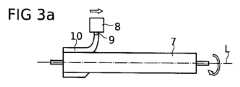
長さに沿って異なる特性、特に異なる曲げ剛性を示すことができるカニューレ4を製造する方法が、図3a~図3dに概略的に示される。本方法の核となる概念は、カニューレが、異なる区域を互いに装着するのではなく、液状材料を心棒などの細長い要素上に分注することによって生成されることである。以下のステップは、概略的に示され、例証の目的のために実寸ではない。特に、簡略性のために、ステップは、各軸区域内の単一の層についてのみ示される。しかしながら、2つ以上、最大20層以上が各軸区域内に塗布されてもよいことを理解されたい。A method for manufacturing a
図3aに示される第1のステップにおいて、基層10が、心棒7上に塗布される。基層10を作成するために、液状材料が、液状材料を分注するために少なくとも1つのノズル9を有する分注器8を用いて心棒7上に塗布される。液状材料を分注している間、心棒7は、カニューレ4の縦軸Lと一致する縦軸Lを中心に回転される。心棒7は、旋盤(図示せず)などの好適な装置を用いて回転されてもよい。回転の速度は、約12rpmであってもよい。分注器8は、心棒7の長さに沿って軸方向に移動される。分注器8の軸速度および心棒7の回転速度は、液状材料の連続層が、長さに沿って、および心棒7の円周の周りに塗布され得るように選択される。最終基層10は、すなわち乾燥および硬化後、約50μm~100μmの厚さを有してもよい。In the first step shown in FIG. 3a, the
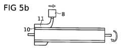
基層10が、心棒7上に完全に塗布され、所望の程度まで少なくとも乾燥した後、図5に関して以下より詳細に説明されるように、液状材料の層11が、基層10と同じ様式で、すなわち、図3bに示されるように、心棒7を回転させながら分注器8を心棒7の長手方向に沿って移動させることによって、塗布される。層11の液状材料は、基層10の材料と同じ材料、または異なる材料であってもよい。同じ分注器8が使用されてもよい。特に、材料が異なる場合、材料は、分注器8の別のノズル、またはおそらくは別の分注器によって分注されてもよい。層11は、カニューレ4の第1の軸区域13の部分であり(図3dを参照のこと)、心棒7の長さの部分に沿ってのみ塗布される。After the
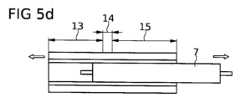
図3cに示されるように、別の液状材料の層12が、上に説明されるものと同じ様式で、すなわち、心棒7を回転させながら分注器8を心棒7の長手方向に沿って移動させることによって、軸方向に層11に隣接して心棒7上に塗布される。層12の材料は、層11の材料と異なってもよい。図3cに示されるように、層12は、層11よりも厚い。層12は、カニューレ4の第2の軸区域15の部分であり(図3dを参照のこと)、心棒7の長さの部分に沿ってのみ塗布される。層11および12は、重複し、互いに混合して、少なくとも10μmの長さにわたって延びる第1の軸区域13と第2の軸区域15との間の平滑な遷移領域14を形成する。As shown in FIG. 3c, a
層11および12の材料および壁厚を適切に選択することにより、第1および第2の軸区域13および15の曲げ剛性を、所望の通りに調節することができる。第1および第2の軸区域13、15は各々、好ましくは、2つ以上の材料層を含むことを理解されたい。言い換えると、2つ以上の層11および2つ以上の層12が、第1の軸区域13および第2の軸区域15をそれぞれ形成するために、心棒7上に塗布される。それ以外に、それぞれの遷移領域によって接続される3つ以上の軸区域が、心棒7上に作成されてもよい。例えば、屈曲部分によって接続される硬い部分を有するカニューレを作成するために、低い曲げ剛性の区域が、高い曲げ剛性の区域と交互になるように作成されてもよい。所望の量の材料が心棒7上に塗布され、十分に硬化された後、心棒7は、図3dに示されるように、カニューレ4から除去される。By appropriately selecting the material and wall thickness of
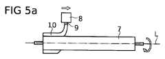
図4a~図4dは、図3a~図3dと実質的に同じ方法を示す。唯一の違いは、層12の材料が層11の材料と同じ材料であることである。第1の軸区域13および第2の軸区域15の異なる曲げ剛性は、異なる壁厚から生じる。図5a~図5dは、図3a~図3dと実質的に同じ方法を示す。この実施形態では、層11および12の材料は異なるが、壁厚は、カニューレ4の長さに沿って一定であり、すなわち、第1の軸区域13および第2の軸区域15の壁厚は同じである。異なる曲げ剛性は、異なる材料から生じる。図5dに特に示されるように、第1および第2の軸区域13、15の異なる材料は、遷移領域14において互いに混合する。代替的に、図5a~5dも参照すると、層11および12の材料は、同じであってもよいが、異なる割合の溶媒を含んで、遷移領域14において互いに混合し得る。例えば、層11は、層12よりも少ない溶媒を含んでもよく、これが、硬化後に層11および12(すなわち、第1および第2の軸区域13、15)の異なる壁厚をもたらすことになる(図示せず)。4a-4d show substantially the same method as in Figs. 3a-3d. The only difference is that the material of
これより図6を参照すると、既に上に簡単に説明されるように、液状材料は、好ましくは、溶媒を含む。各材料内の溶媒の割合は、80vol%超、好ましくは90vol%超であってもよい。原則は、図6において層11に関して例示的に示される。図6は、溶媒の蒸発前(左)および溶媒の蒸発後(右)の心棒7上に塗布される層11を示す。「物理的に乾燥する」とも表され得る、溶媒の蒸発後、塗布の厚さは、おおよそ溶媒の量だけ低減される。高割合の溶媒を使用することは、塗布された材料の大半が蒸発するため、超薄層の製造を促進する。言い換えると、比較的大量の材料が分注され得る一方で、ほんの少量の材料しか完成したカニューレ4内には存在しないことになる。これは、薄層を作成するために溶媒なしに少量を塗布するよりも簡単であり、分注器に対してそれほど精度を必要としない。With reference now to FIG. 6, as already briefly explained above, the liquid materials preferably contain a solvent. The proportion of solvent in each material may be more than 80 vol.%, preferably more than 90 vol.%. The principle is exemplarily illustrated in FIG. 6 for a
図7~図11は、カニューレ4において単独または任意の組み合わせのいずれかで含まれ得る異なる態様を示す。簡略性のため、カニューレ4は、図7~図11では一体となった部品として示される。しかしながら、カニューレ4は、上に説明されるように、異なる層および軸区域を含む。FIGS. 7-11 show different aspects that may be included in the
図7に示されるカニューレ4は、カニューレ4の壁に埋め込まれた補剛構造体16を含む。補剛構造体16は、カニューレ4のまわりに延びるらせん形状を有し得るか、またはカニューレ4を強化する任意の他の好適なパターンを形成し得る。補剛構造体16は、分注器8を用いて液状材料を分注することによって作成されてもよい。しかしながら、上に説明されるように連続した層を作成するのではなく、補剛構造体16のための液状材料は、らせん状の経路に沿って心棒7上に塗布される。この材料は、補剛構造体16がカニューレ4の壁に埋め込まれるように、先に作成された層の上に塗布され、後続の層によって被覆される。例えば、補剛構造体16は、ポリウレタン製であってもよく、一方で周囲材料は、ポリウレタンよりも軟らかいポリエチレンである。特に、補剛構造体16は、カニューレ4の壁の残部よりも高い弾性率を有する。7 includes a stiffening structure 16 embedded in the wall of the
代替的に、または追加的に、カニューレは、事前に巻かれて、カニューレ4の壁に埋め込まれるために分注プロセス中にカニューレ4に組み込まれるらせん状ニチノールワイヤで形成された補剛構造体を含んでもよい。さらに代替的には、ポリマースレッドが、カニューレの材料層間に心棒の周りに巻かれてもよい。上で述べられるように、任意の上記補剛構造体は、有利には、カニューレ4の層間に埋め込まれる。例えば、第1の材料層が塗布された後に補剛構造体が続いてもよく(例えば、経路に沿った液状材料、事前に巻かれたニチノールワイヤまたはポリマースレッド)、この補剛構造体は、続いて1つ以上のさらなる材料層によって被覆される。これは、図7において層10および11によって例示的に示される。カニューレ4は、図7の層10および11よりも多くの層を含んでもよいことを理解されたい。Alternatively or additionally, the cannula may include a stiffening structure formed of a helical Nitinol wire that is pre-wound and incorporated into the
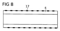
これより図8を参照すると、カニューレ4は、例えば、周囲材料とは異なる色を示すことによって人間の目によって可視である、またはx線下で可視である、すなわち放射線不透過性である標識17を有して示される。標識17は、カニューレ4上に塗布され得るか、またはカニューレ4に埋め込まれ得る。標識は、らせん状の経路に沿って、または任意の他の所望の経路に沿って延びてもよい。標識は、補剛構造体16に関して上に説明されるように液状材料を分注することによって製造されてもよい。また、上に説明されるようなワイヤまたはスレッドが、標識を伴ってもよい。例えば、ワイヤまたはスレッドは、放射線不透過性であってもよい。8, the
図9は、周方向ショルダ部18を有するカニューレ4を示し、すなわち、カニューレ4が、区域25、26を有し、これら区域のそれぞれの内径および外径は異なる。したがって、心棒7は、異なる直径を有する2つの心棒部分7a、7bを相互接続するそれぞれの周方向ショルダ部24を有する。最終カニューレ4からの心棒7の除去を促進するために、部分7a、7bは分離可能である。Figure 9 shows a
図10に示されるカニューレ4は、カニューレ4の壁を通って延びる管腔19を有する。管腔19は、上記分注方法の間にフィラメント20を組み込むことによって作成され得る。フィラメント20が中実である場合、これは、カニューレ4の生成が完成して管腔19を形成した後に、カニューレ4から引き出されることになる。代替的に、カニューレ4に埋め込まれて管腔19を形成する中空のフィラメントが使用されてもよい。The
カニューレ4を製造する方法は、図11に示されるように、カニューレ4内に少なくとも1つの開口部、例えば、前述の血液流入口2を作成するステップをさらに含んでもよい。ケージ構造体21または同様のものが、開口部2を形成するために分注器8を用いて作成されてもよい。この目的のため、心棒7は、好ましくは、ケージ構造体21の所望の形状に応じて、回転されないか、または非常に緩徐に回転される。例えば、長手方向の支柱が作成される場合、心棒7は回転されるべきではない。ケージ構造体21の分注材料の粘度は、材料が心棒7から滴下しないが、一体となった本体を形成するために、カニューレ4の以前にまたは続いて塗布される層と混合するように選択される。The method for manufacturing the
上に説明されるような分注ステップを含むカニューレを製造する方法は、任意の所望の構造体を含む、カニューレの長さに沿って調節可能な特性を有するカニューレの製造を可能にする。上述の機能は、単独または組み合わせでカニューレに含まれてもよい。壁厚は、材料の種類、材料の分注量、分注速度、心棒および分注器の一方または両方の移動の速度、ならびに材料内の溶媒の割合などの様々なパラメータによって影響を受けることがある。任意の所望の数、順序、および配置の層がカニューレに含まれてもよいことを理解されたい。曲げ剛性などの異なる特性を有する、任意の数、順序、および配置の軸区域が、所望の通りに作成されてもよい。説明される実施形態は、例証の目的のためであり、限定することは意図されない。本発明は、添付の特許請求の範囲において規定される。
The method of manufacturing a cannula including a dispensing step as described above allows for the manufacture of a cannula with adjustable properties along its length, including any desired structure. The above-mentioned features may be included in the cannula alone or in combination. The wall thickness may be affected by various parameters such as the type of material, the amount of material dispensed, the dispensing speed, the speed of movement of the mandrel and/or dispenser, and the percentage of solvent in the material. It is understood that any desired number, order, and arrangement of layers may be included in the cannula. Any number, order, and arrangement of axial sections with different properties, such as bending stiffness, may be created as desired. The described embodiments are for illustrative purposes and are not intended to be limiting. The invention is defined in the appended claims.
Claims (36)
Translated fromJapanese少なくとも1つの分注器(8)を用いて第1の液状材料を心棒(7)上に分注し、それと同時に前記心棒(7)および前記分注器(8)が、軸方向および前記心棒(7)の周方向に、互いに対して移動することによって、前記細長い管状本体の第1の軸区域(13)を形成するステップと、
前記少なくとも1つの分注器(8)を用いて第2の液状材料を前記心棒(7)上に分注し、それと同時に前記心棒(7)および前記分注器(8)が、軸方向および前記心棒(7)の周方向に、互いに対して移動することによって、前記細長い管状本体の第2の軸区域(15)を形成するステップと、を含み、
前記第1および第2の軸区域(13、15)が、異なる曲げ剛性を有するように形成され、前記第1および第2の液状材料が遷移領域(14)を形成するように、前記第1および第2の液状材料が前記心棒(7)上に分注され、
前記第1および第2の液状材料が、それぞれ前記第1の軸区域(13)の第1の壁厚および前記第2の軸区域(15)の第2の壁厚を形成するために前記心棒(7)上に分注され、乾燥したときの前記第1の壁厚が、乾燥したときの前記第2の壁厚とは異なり、前記異なる曲げ剛性が、異なる壁厚から生じる、ことを特徴とする方法。 A method for manufacturing a cannula (4) for an intravascular blood pump for percutaneous insertion into a blood vessel of a patient, said cannula (4) having an elongated tubular body with a blood inlet and a blood outlet, said method comprising:
dispensing a first liquid material onto a mandrel (7) using at least one dispenser (8) while said mandrel (7) and said dispenser (8) move relative to each other in an axial direction and in a circumferential direction of said mandrel (7) to form a first axial section (13) of said elongated tubular body;
dispensing a second liquid material onto the mandrel (7) using the at least one dispenser (8) while the mandrel (7) and the dispenser (8) move relative to each other in the axial direction and in the circumferential direction of the mandrel (7) to form a second axial section (15) of the elongated tubular body;
Thefirst and second liquid materials are dispensed onto the mandrel (7) such that the first and second axial sections (13, 15) are formed to have different bending stiffnesses and the firstand second liquid materials form a transition region (14);
wherein the first and second liquid materials are dispensed onto the mandrel (7) to form a first wall thickness in the first axial section (13) and a second wall thickness in the second axial section (15), respectively, and wherein the first wall thickness when dried differs from the second wall thickness when dried, and the different bending stiffnesses result from the different wall thicknesses.
前記第1の軸区域(13)が、第1の壁厚を有し、前記第2の軸区域(15)が、第2の壁厚を有し、前記第1および第2の軸区域(13、15)は壁厚が異なり、前記異なる曲げ剛性が、異なる壁厚から生じる、ことを特徴とする方法。 14. The method according to any one of claims 1 to 13, wherein the cannula (4) has an elongated tubular body with a blood inlet and a blood outlet, the body comprisingthe first axial section (13) containing the firstliquid material and the second axial section (15) containing thesecondliquid material, the first and second axial sections (13, 15) having different bending stiffnesses, the first and secondliquid materials mixing with each other in a transition region (14),
The method according to claim 1, wherein the first axial region (13) has a first wall thickness and the second axial region (15) has a second wall thickness, the first and second axial regions (13, 15) having different wall thicknesses, and the different bending stiffnesses result from the different wall thicknesses.
前記第1の軸区域(13)が、第1の壁厚を有し、前記第2の軸区域(15)が、第2の壁厚を有し、前記第1および第2の軸区域(13、15)は壁厚が異なり、前記異なる曲げ剛性が、異なる壁厚から生じる、ことを特徴とする方法。 14. The method according to any one of claims 1 to 13, wherein the cannula (4) has an elongated tubular body with a blood inlet and a blood outlet, the body comprisingthe first axial section (13) containing the firstliquid material and the second axial section (15) containing the secondliquid material,the first and second axial sections (13, 15) having different bending stiffnesses, the first and secondliquid materials being different and overlapping axially in the transition region (14),
The method according to claim 1, wherein the first axial region (13) has a first wall thickness and the second axial region (15) has a second wall thickness, the first and second axial regions (13, 15) having different wall thicknesses, and the different bending stiffnesses result from the different wall thicknesses.
前記心棒(7)が、約10~15rpmの速度で回転される、ことを特徴とする方法。 4. The method of claim 3,
A method characterized in that the mandrel (7) is rotated at a speed of about 10 to 15 rpm.
前記心棒(7)が、約12rpmの速度で回転される、ことを特徴とする方法。 4. The method of claim 3,
A method according to any one of claims 1 to 5, characterised in that the mandrel (7) is rotated at a speed of about 12 rpm.
前記基層(10)が、前記心棒(7)の長さに対して実質的に均一な量の前記第3の液状材料を分注することによって形成される、ことを特徴とする方法。 6. The method of claim 5,
The method of claim 1, wherein the substrate (10) is formed by dispensing a substantially uniform amount of the third liquid material along the length of the mandrel (7).
前記基層(10)が、乾燥したときに約50μm~100μmの厚さを有する、ことを特徴とする方法。 28. The method of claim 5 or 27,
The method of claim 1, wherein said base layer (10) has a thickness of about 50 μm to 100 μm when dry.
前記第1および第2の液状材料が、前記補剛構造体(16)を前記カニューレの本体に埋め込むように、前記第4の液状材料を分注する前および後の両方に分注される、ことを特徴とする方法。 7. The method of claim 6,
wherein the first and second liquid materials are dispensed both before and after dispensing the fourthliquid material so as to embed the stiffening structure (16) into the body of the cannula.
前記溶媒の割合が、少なくとも80vol%である、ことを特徴とする方法。 8. The method of claim 7,
The method according to claim 1, wherein the proportion of the solvent is at least 80 vol. %.
前記溶媒の割合が、少なくとも90vol%である、ことを特徴とする方法。 8. The method of claim 7,
The method according to claim 1, wherein the proportion of the solvent is at least 90 vol. %.
前記心棒(7)の前記2つの軸方向隣接部分(7a、7b)が、前記カニューレ(4)を前記心棒(7)から除去するために互いから分離される、ことを特徴とする方法。 10. The method of claim 9,
The method according to claim 1, characterized in that the two axially adjacent portions (7a, 7b) of the mandrel (7) are separated from each other in order to remove the cannula (4) from the mandrel (7).
前記少なくとも1つの標識(17)が、前記分注器(8)を用いて液状材料を分注することによって形成される、ことを特徴とする方法。 11. The method of claim 10,
The method of claim 1, wherein said at least one mark (17) is formed by dispensing a liquid material using said dispenser (8).
前記らせん状ワイヤが、金属製である、ことを特徴とする方法。 20. The method of claim 18,
4. The method of claim 3, wherein the spiral wire is made of metal.
前記らせん状ワイヤが、ニチノール製である、ことを特徴とする方法。 20. The method of claim 18,
The method of claim 1, wherein the helical wire is made of Nitinol.
Priority Applications (1)
| Application Number | Priority Date | Filing Date | Title |
|---|---|---|---|
| JP2024125725AJP2024144664A (en) | 2017-06-21 | 2024-08-01 | Cannula for intravascular blood pump |
Applications Claiming Priority (5)
| Application Number | Priority Date | Filing Date | Title |
|---|---|---|---|
| EP17177180 | 2017-06-21 | ||
| EP17177180.1 | 2017-06-21 | ||
| EP17184552.2 | 2017-08-02 | ||
| EP17184552.2AEP3437668A1 (en) | 2017-06-21 | 2017-08-02 | Cannula for intravascular blood pump |
| PCT/EP2018/066590WO2018234454A1 (en) | 2017-06-21 | 2018-06-21 | CANNULA FOR AN INTRAVASCULAR BLOOD PUMP |
Related Child Applications (1)
| Application Number | Title | Priority Date | Filing Date |
|---|---|---|---|
| JP2024125725ADivisionJP2024144664A (en) | 2017-06-21 | 2024-08-01 | Cannula for intravascular blood pump |
Publications (3)
| Publication Number | Publication Date |
|---|---|
| JP2020524583A JP2020524583A (en) | 2020-08-20 |
| JP2020524583A5 JP2020524583A5 (en) | 2021-07-26 |
| JP7534088B2true JP7534088B2 (en) | 2024-08-14 |
Family
ID=59101354
Family Applications (2)
| Application Number | Title | Priority Date | Filing Date |
|---|---|---|---|
| JP2019571314AActiveJP7534088B2 (en) | 2017-06-21 | 2018-06-21 | Method for manufacturing a cannula for an intravascular blood pump |
| JP2024125725APendingJP2024144664A (en) | 2017-06-21 | 2024-08-01 | Cannula for intravascular blood pump |
Family Applications After (1)
| Application Number | Title | Priority Date | Filing Date |
|---|---|---|---|
| JP2024125725APendingJP2024144664A (en) | 2017-06-21 | 2024-08-01 | Cannula for intravascular blood pump |
Country Status (10)
| Country | Link |
|---|---|
| US (2) | US11752322B2 (en) |
| EP (3) | EP3437668A1 (en) |
| JP (2) | JP7534088B2 (en) |
| KR (2) | KR102611233B1 (en) |
| CN (1) | CN110785191A (en) |
| AU (2) | AU2018288541B2 (en) |
| DK (1) | DK3641845T3 (en) |
| ES (1) | ES3010337T3 (en) |
| IL (1) | IL270715A (en) |
| SG (1) | SG11201910969VA (en) |
Families Citing this family (13)
| Publication number | Priority date | Publication date | Assignee | Title |
|---|---|---|---|---|
| DE102018207575A1 (en) | 2018-05-16 | 2019-11-21 | Kardion Gmbh | Magnetic face turning coupling for the transmission of torques |
| DE102018208555A1 (en) | 2018-05-30 | 2019-12-05 | Kardion Gmbh | Apparatus for anchoring a cardiac assist system in a blood vessel, method of operation, and method of making a device and cardiac assist system |
| DE102018208541A1 (en) | 2018-05-30 | 2019-12-05 | Kardion Gmbh | Axial pump for a cardiac assist system and method of making an axial pump for a cardiac assist system |
| DE102018208538A1 (en) | 2018-05-30 | 2019-12-05 | Kardion Gmbh | Intravascular blood pump and process for the production of electrical conductors |
| DE102018208539A1 (en) | 2018-05-30 | 2019-12-05 | Kardion Gmbh | A motor housing module for sealing an engine compartment of a motor of a cardiac assist system and cardiac assistance system and method for mounting a cardiac assist system |
| DE102018208550A1 (en) | 2018-05-30 | 2019-12-05 | Kardion Gmbh | A lead device for directing blood flow to a cardiac assist system, cardiac assist system, and method of making a lead device |
| DE102018210076A1 (en) | 2018-06-21 | 2019-12-24 | Kardion Gmbh | Method and device for detecting a state of wear of a cardiac support system, method and device for operating a cardiac support system and cardiac support system |
| DE102018210058A1 (en) | 2018-06-21 | 2019-12-24 | Kardion Gmbh | Stator blade device for guiding the flow of a fluid flowing out of an outlet opening of a heart support system, heart support system with stator blade device, method for operating a stator blade device and manufacturing method |
| CN112654389A (en) | 2018-08-07 | 2021-04-13 | 开迪恩有限公司 | Bearing device for a cardiac support system and method for flushing an intermediate space in a bearing device for a cardiac support system |
| EP3990044B1 (en)* | 2019-06-28 | 2025-05-07 | Abiomed, Inc. | Double thermoform cannula |
| JP2025502424A (en)* | 2022-01-20 | 2025-01-24 | ボストン サイエンティフィック サイムド,インコーポレイテッド | Percutaneous circulatory support device including a guidewire distal tip portion - Patents.com |
| EP4531970A2 (en)* | 2022-05-25 | 2025-04-09 | Boston Scientifc Scimed. Inc. | Devices, systems, and methods for delivering fluid through a tubular element |
| CN117018427B (en)* | 2023-08-10 | 2024-03-08 | 苏州心岭迈德医疗科技有限公司 | An interventional spring tube assembly, an interventional blood pump and a manufacturing method thereof |
Citations (3)
| Publication number | Priority date | Publication date | Assignee | Title |
|---|---|---|---|---|
| US20040065979A1 (en) | 2001-02-26 | 2004-04-08 | Wang James C. | Injector tip-and-die assembly construction and method |
| JP2007503916A (en) | 2003-09-02 | 2007-03-01 | アボット・ラボラトリーズ | Medical device delivery system |
| CN102341141A (en) | 2009-03-09 | 2012-02-01 | 住友电木株式会社 | Catheter and method of manufacturing catheter |
Family Cites Families (16)
| Publication number | Priority date | Publication date | Assignee | Title |
|---|---|---|---|---|
| US4250072A (en) | 1979-05-18 | 1981-02-10 | Flynn Vincent J | Radiopaque polyurethane resin compositions |
| US4675361A (en)* | 1980-02-29 | 1987-06-23 | Thoratec Laboratories Corp. | Polymer systems suitable for blood-contacting surfaces of a biomedical device, and methods for forming |
| AU2807389A (en) | 1987-12-07 | 1989-07-05 | Nimbus Medical, Inc. | Inflow cannula for intravascular blood pumps |
| US5533985A (en)* | 1994-04-20 | 1996-07-09 | Wang; James C. | Tubing |
| US5403292A (en)* | 1994-05-18 | 1995-04-04 | Schneider (Usa) Inc. | Thin wall catheter having enhanced torqueability characteristics |
| US5951929A (en)* | 1995-12-12 | 1999-09-14 | Medi-Dyne Inc. | Method for forming a catheter having overlapping welds |
| US5827242A (en)* | 1996-06-21 | 1998-10-27 | Medtronic, Inc. | Reinforced catheter body and method for its fabrication |
| US6007478A (en)* | 1997-11-13 | 1999-12-28 | Impella Cardiotechnik Aktiengesellschaft | Cannula having constant wall thickness with increasing distal flexibility and method of making |
| EP1034808A1 (en)* | 1999-03-09 | 2000-09-13 | Paul Frederik Gründeman | A device for transventricular mechanical circulatory support |
| US7022100B1 (en) | 1999-09-03 | 2006-04-04 | A-Med Systems, Inc. | Guidable intravascular blood pump and related methods |
| US6929766B2 (en)* | 2002-06-14 | 2005-08-16 | Edwards Lifesciences Corporation | Dispense molding method and apparatus for manufacturing cannulae |
| US8485961B2 (en)* | 2011-01-05 | 2013-07-16 | Thoratec Corporation | Impeller housing for percutaneous heart pump |
| US9358329B2 (en)* | 2012-07-03 | 2016-06-07 | Thoratec Corporation | Catheter pump |
| EP2868331B1 (en)* | 2013-11-01 | 2016-07-13 | ECP Entwicklungsgesellschaft mbH | Pump, in particular blood pump |
| US9855371B2 (en)* | 2014-04-28 | 2018-01-02 | John James Scanlon | Bioresorbable stent |
| EP4046678B1 (en)* | 2014-05-13 | 2025-10-01 | Abiomed, Inc. | Cannula assembly |
- 2017
- 2017-08-02EPEP17184552.2Apatent/EP3437668A1/ennot_activeWithdrawn
- 2018
- 2018-06-21KRKR1020207000939Apatent/KR102611233B1/enactiveActive
- 2018-06-21EPEP24214525.8Apatent/EP4487899A3/enactivePending
- 2018-06-21JPJP2019571314Apatent/JP7534088B2/enactiveActive
- 2018-06-21SGSG11201910969VApatent/SG11201910969VA/enunknown
- 2018-06-21CNCN201880041629.7Apatent/CN110785191A/enactivePending
- 2018-06-21AUAU2018288541Apatent/AU2018288541B2/enactiveActive
- 2018-06-21EPEP18732783.8Apatent/EP3641845B1/enactiveActive
- 2018-06-21USUS16/625,491patent/US11752322B2/enactiveActive
- 2018-06-21KRKR1020237041800Apatent/KR20230170137A/ennot_activeCeased
- 2018-06-21DKDK18732783.8Tpatent/DK3641845T3/enactive
- 2018-06-21ESES18732783Tpatent/ES3010337T3/enactiveActive
- 2019
- 2019-11-17ILIL270715Apatent/IL270715A/enunknown
- 2023
- 2023-07-28USUS18/227,342patent/US20240058593A1/enactivePending
- 2024
- 2024-06-24AUAU2024204311Apatent/AU2024204311A1/enactivePending
- 2024-08-01JPJP2024125725Apatent/JP2024144664A/enactivePending
Patent Citations (3)
| Publication number | Priority date | Publication date | Assignee | Title |
|---|---|---|---|---|
| US20040065979A1 (en) | 2001-02-26 | 2004-04-08 | Wang James C. | Injector tip-and-die assembly construction and method |
| JP2007503916A (en) | 2003-09-02 | 2007-03-01 | アボット・ラボラトリーズ | Medical device delivery system |
| CN102341141A (en) | 2009-03-09 | 2012-02-01 | 住友电木株式会社 | Catheter and method of manufacturing catheter |
Also Published As
| Publication number | Publication date |
|---|---|
| US20210402170A1 (en) | 2021-12-30 |
| DK3641845T3 (en) | 2025-02-17 |
| AU2018288541A1 (en) | 2019-12-12 |
| AU2018288541B2 (en) | 2024-03-28 |
| EP3641845B1 (en) | 2024-11-27 |
| EP3641845A1 (en) | 2020-04-29 |
| KR20230170137A (en) | 2023-12-18 |
| EP3437668A1 (en) | 2019-02-06 |
| IL270715A (en) | 2020-01-30 |
| KR20200020792A (en) | 2020-02-26 |
| AU2024204311A1 (en) | 2024-07-11 |
| EP4487899A3 (en) | 2025-03-26 |
| CN110785191A (en) | 2020-02-11 |
| SG11201910969VA (en) | 2020-01-30 |
| JP2020524583A (en) | 2020-08-20 |
| US20240058593A1 (en) | 2024-02-22 |
| EP3437668A8 (en) | 2019-05-15 |
| JP2024144664A (en) | 2024-10-11 |
| US11752322B2 (en) | 2023-09-12 |
| KR102611233B1 (en) | 2023-12-08 |
| EP4487899A2 (en) | 2025-01-08 |
| ES3010337T3 (en) | 2025-04-02 |
Similar Documents
| Publication | Publication Date | Title |
|---|---|---|
| JP7534088B2 (en) | Method for manufacturing a cannula for an intravascular blood pump | |
| WO2018234454A1 (en) | CANNULA FOR AN INTRAVASCULAR BLOOD PUMP | |
| JP7059345B2 (en) | Inflatable medical balloon with continuous fiber winding | |
| JP3645109B2 (en) | Medical tube and manufacturing method thereof | |
| US5704926A (en) | Flexible catheter | |
| US7507229B2 (en) | Wire braid-reinforced microcatheter | |
| JP3641381B2 (en) | Medical tube and manufacturing method thereof | |
| JP2020524583A5 (en) | ||
| US9180028B2 (en) | Structural hydrogel polymer device | |
| JPH08508928A (en) | Catheter with kink-resistant distal tip | |
| JP2001501846A (en) | Guide catheter with enhanced guidewire tracking | |
| WO2017027287A1 (en) | Integrated adaptive seal for prosthetic heart valves | |
| CN117051600A (en) | Processing methods of medical catheters | |
| US10918835B2 (en) | Delivery system for active agent coated balloon | |
| HK40022849A (en) | Cannula for intravascular blood pump | |
| HK40022849B (en) | Cannula for intravascular blood pump | |
| JP4964732B2 (en) | System and method for coating a catheter shaft | |
| WO2024116319A1 (en) | Medical device and method of manufacturing medical device | |
| JPH0332376B2 (en) | ||
| JP2018187229A (en) | Medical long body | |
| JP2672714B2 (en) | Untwisted spiral wound catheter | |
| WO2025064248A1 (en) | Catheter with marker device and polymeric tip | |
| JPH0374588B2 (en) |
Legal Events
| Date | Code | Title | Description |
|---|---|---|---|
| A521 | Request for written amendment filed | Free format text:JAPANESE INTERMEDIATE CODE: A523 Effective date:20210611 | |
| A621 | Written request for application examination | Free format text:JAPANESE INTERMEDIATE CODE: A621 Effective date:20210611 | |
| A977 | Report on retrieval | Free format text:JAPANESE INTERMEDIATE CODE: A971007 Effective date:20220701 | |
| A131 | Notification of reasons for refusal | Free format text:JAPANESE INTERMEDIATE CODE: A131 Effective date:20220906 | |
| A521 | Request for written amendment filed | Free format text:JAPANESE INTERMEDIATE CODE: A523 Effective date:20221205 | |
| A131 | Notification of reasons for refusal | Free format text:JAPANESE INTERMEDIATE CODE: A131 Effective date:20230411 | |
| A521 | Request for written amendment filed | Free format text:JAPANESE INTERMEDIATE CODE: A523 Effective date:20230710 | |
| A131 | Notification of reasons for refusal | Free format text:JAPANESE INTERMEDIATE CODE: A131 Effective date:20231024 | |
| A601 | Written request for extension of time | Free format text:JAPANESE INTERMEDIATE CODE: A601 Effective date:20240122 | |
| TRDD | Decision of grant or rejection written | ||
| A01 | Written decision to grant a patent or to grant a registration (utility model) | Free format text:JAPANESE INTERMEDIATE CODE: A01 Effective date:20240702 | |
| A61 | First payment of annual fees (during grant procedure) | Free format text:JAPANESE INTERMEDIATE CODE: A61 Effective date:20240801 | |
| R150 | Certificate of patent or registration of utility model | Ref document number:7534088 Country of ref document:JP Free format text:JAPANESE INTERMEDIATE CODE: R150 |