JP7533899B2 - Intramedullary nails for lengthening long bones - Google Patents
Intramedullary nails for lengthening long bonesDownload PDFInfo
- Publication number
- JP7533899B2 JP7533899B2JP2022506445AJP2022506445AJP7533899B2JP 7533899 B2JP7533899 B2JP 7533899B2JP 2022506445 AJP2022506445 AJP 2022506445AJP 2022506445 AJP2022506445 AJP 2022506445AJP 7533899 B2JP7533899 B2JP 7533899B2
- Authority
- JP
- Japan
- Prior art keywords
- coil
- tube
- nail
- region
- locking
- Prior art date
- Legal status (The legal status is an assumption and is not a legal conclusion. Google has not performed a legal analysis and makes no representation as to the accuracy of the status listed.)
- Active
Links
Images


Classifications
- A—HUMAN NECESSITIES
- A61—MEDICAL OR VETERINARY SCIENCE; HYGIENE
- A61B—DIAGNOSIS; SURGERY; IDENTIFICATION
- A61B17/00—Surgical instruments, devices or methods
- A61B17/56—Surgical instruments or methods for treatment of bones or joints; Devices specially adapted therefor
- A61B17/58—Surgical instruments or methods for treatment of bones or joints; Devices specially adapted therefor for osteosynthesis, e.g. bone plates, screws or setting implements
- A61B17/68—Internal fixation devices, including fasteners and spinal fixators, even if a part thereof projects from the skin
- A61B17/72—Intramedullary devices, e.g. pins or nails
- A61B17/7216—Intramedullary devices, e.g. pins or nails for bone lengthening or compression
- A—HUMAN NECESSITIES
- A61—MEDICAL OR VETERINARY SCIENCE; HYGIENE
- A61B—DIAGNOSIS; SURGERY; IDENTIFICATION
- A61B17/00—Surgical instruments, devices or methods
- A61B17/56—Surgical instruments or methods for treatment of bones or joints; Devices specially adapted therefor
- A61B17/58—Surgical instruments or methods for treatment of bones or joints; Devices specially adapted therefor for osteosynthesis, e.g. bone plates, screws or setting implements
- A61B17/68—Internal fixation devices, including fasteners and spinal fixators, even if a part thereof projects from the skin
- A61B17/72—Intramedullary devices, e.g. pins or nails
- A61B17/7233—Intramedullary devices, e.g. pins or nails with special means of locking the nail to the bone
- A—HUMAN NECESSITIES
- A61—MEDICAL OR VETERINARY SCIENCE; HYGIENE
- A61B—DIAGNOSIS; SURGERY; IDENTIFICATION
- A61B17/00—Surgical instruments, devices or methods
- A61B2017/00367—Details of actuation of instruments, e.g. relations between pushing buttons, or the like, and activation of the tool, working tip, or the like
- A61B2017/00411—Details of actuation of instruments, e.g. relations between pushing buttons, or the like, and activation of the tool, working tip, or the like actuated by application of energy from an energy source outside the body
Landscapes
- Health & Medical Sciences (AREA)
- Orthopedic Medicine & Surgery (AREA)
- Surgery (AREA)
- Life Sciences & Earth Sciences (AREA)
- Heart & Thoracic Surgery (AREA)
- Nuclear Medicine, Radiotherapy & Molecular Imaging (AREA)
- Engineering & Computer Science (AREA)
- Biomedical Technology (AREA)
- Neurology (AREA)
- Medical Informatics (AREA)
- Molecular Biology (AREA)
- Animal Behavior & Ethology (AREA)
- General Health & Medical Sciences (AREA)
- Public Health (AREA)
- Veterinary Medicine (AREA)
- Surgical Instruments (AREA)
Description
Translated fromJapanese本発明は、長骨を伸展させるための髄内釘に関する。The present invention relates to an intramedullary nail for lengthening long bones.
[最先端技術]
髄内釘は、最先端技術から公知であり、細長い長骨が伸展することを可能にする。髄内釘によって、2つの骨断片、第1の骨断片および第2の骨断片は、互いに対して移動される。骨は、2つの骨断片間の接触点において新しく成長することが意図される。これは、伸展のための髄内釘の駆動部の供給速度が十分に低くなるように選択することによって達成される。駆動部のためのエネルギを髄内釘に、経皮的に供給することが公知である。EP1033112B1から、髄内釘のハウジング内または髄内釘のハウジングの外側の正面に配された受信アンテナが公知である。 [Cutting-edge technology]
Intramedullary nails are known from the state of the art and allow elongated long bones to be lengthened. With the intramedullary nail, two bone fragments, a first bone fragment and a second bone fragment, are moved relative to each other. Bone is intended to grow anew at the contact point between the two bone fragments. This is achieved by selecting the supply speed of the drive of the intramedullary nail for lengthening to be sufficiently low. It is known to supply the energy for the drive to the intramedullary nail percutaneously. From
しかしながら、最先端技術からこれまで知られている解決法には、エネルギ伝達性能またはエネルギ伝達の効率の観点から制限があり、より大きい空間を必要とするか、または髄内釘が髄内釘の外側に配された受信アンテナと連結していることを必要とする。However, the solutions known so far from the state of the art have limitations in terms of energy transmission performance or efficiency of energy transmission, require larger space or require the intramedullary nail to be coupled with a receiving antenna arranged outside the intramedullary nail.
最先端技術に対して向上された髄内釘を提案することが本発明の課題である。具体的には、髄内釘は、高いエネルギ伝達性能を可能にするべきであるか、高効率のエネルギ伝達を有するべきであるか、骨中で空間をほとんど占めるべきではないか、または関節近くに埋め込むことが可能であるべきである。さらに、可能な限り少ない外科的作業を必要とする、または骨断片中の確実な固定を可能にする髄内釘が望ましい。It is the object of the present invention to propose an improved intramedullary nail with respect to the state of the art. In particular, the intramedullary nail should allow high energy transmission performance, should have a highly efficient energy transmission, should take up little space in the bone or should be capable of being implanted close to the joint. Furthermore, an intramedullary nail is desirable which requires as few surgical operations as possible or allows a secure fixation in the bone fragments.
本発明の一態様によれば、長骨を伸展するための髄内釘であって、髄内釘の軸方向に延在する第1のチューブと、髄内釘の軸方向に延在し、第1のチューブに、互いの内部で軸方向に動くことが可能なように連結された第2のチューブと、第2のチューブから反対に向いた第1のチューブの端部領域にある第1のロック開口と、第1のロック開口と第2のチューブとの間の、第1のチューブのコイル領域に配されたコイルとを有する、髄内釘が提供される。According to one aspect of the present invention, there is provided an intramedullary nail for lengthening a long bone, the intramedullary nail having a first tube extending axially through the nail, a second tube extending axially through the nail and connected to the first tube so as to be axially movable within each other, a first locking opening in an end region of the first tube facing away from the second tube, and a coil disposed in a coil region of the first tube between the first locking opening and the second tube.
本明細書に記載される典型的な実施形態のうちの1つにおいて、本発明のさらなる態様は、一次コイルから髄内釘のコイルにエネルギを伝達するための方法であって、一次コイルを通電する段階と、一次コイルを通電することによって放出された電磁エネルギの少なくとも一部を、髄内釘のコイルによって受け取る段階とを含む方法に関する。In one of the exemplary embodiments described herein, a further aspect of the invention relates to a method for transferring energy from a primary coil to a coil of an intramedullary nail, the method including energizing the primary coil and receiving, by the coil of the intramedullary nail, at least a portion of the electromagnetic energy emitted by energizing the primary coil.
例示的な髄内釘は、細長い長骨の骨折または他の損傷を治療するのに特に好適であり、ここで、他の損傷とは例えば、腫瘍、または暴力の衝撃に起因する骨量減少であり得る。典型的な髄内釘を用いて治療することができる骨は、大腿骨(大腿骨)および脛骨(脛骨)であるが、上腕骨(上腕骨)、エル骨(ell bone)(尺骨)、橈骨(橈骨)、腓骨(腓骨)も治療することができる。The exemplary intramedullary nail is particularly suitable for treating fractures or other injuries of elongated long bones, where the other injuries may be, for example, tumors, or bone loss resulting from violent impact. Bones that may be treated with a typical intramedullary nail are the femur (thigh bone) and tibia (shin bone), but also the humerus (upper arm bone), ell bone (ulna), radius (radius bone), and fibula (fibula).
典型的な実施形態において、第2のチューブは、第1のチューブ内で軸方向に動かすことが可能である。さらなる典型的な実施形態において、第1のチューブは、第2のチューブ内で軸方向に動かすことが可能である。典型的には、本明細書における「軸方向」および「半径方向」という用語は、髄内釘の長軸に対して理解されるべきであり、長軸は、具体的には、髄内釘、または髄内釘の最も大きい空間的拡張に沿って延在する。具体的には、軸方向は、髄内釘の長軸に沿った、またはそれに平行な方向と理解されるべきであり、半径方向は、長軸に対して直交する方向と理解されるべきである。髄内釘の長軸はまた、湾曲していてもよく、例えば、下腿に関する、Herzogによる連続的な曲がりを有する髄内釘におけるものである。典型的に、髄内釘は、髄内釘の長軸に対する断面が少なくとも実質的に円形である。In an exemplary embodiment, the second tube is movable axially within the first tube. In a further exemplary embodiment, the first tube is movable axially within the second tube. Typically, the terms "axial" and "radial" herein should be understood with respect to the long axis of the nail, which specifically extends along the nail or its greatest spatial extension. Specifically, axial should be understood as a direction along or parallel to the long axis of the nail, and radial should be understood as a direction perpendicular to the long axis. The long axis of the nail may also be curved, for example, as in an intramedullary nail with a continuous bend according to Herzog, with respect to the crura. Typically, the nail is at least substantially circular in cross section relative to the long axis of the nail.
典型的な実施形態において、コイルは受け取りコイルとして、または二次コイルとして実現される。コイルは典型的に、具体的には髄内釘の駆動部を作動させるために、体外に配されている一次コイルからエネルギを受け取るように配置される。一次コイルは典型的に、トロイダルコイルとしてまたは鞍形コイルとして実現される。典型的に、コイルは第1のチューブに割り当てられる。典型的に、コイルは、第1のチューブ中に、またはそれにおいて配される。In a typical embodiment, the coil is realized as a receiving coil or as a secondary coil. The coil is typically arranged to receive energy from a primary coil arranged outside the body, in particular to activate a drive part of an intramedullary nail. The primary coil is typically realized as a toroidal coil or as a saddle coil. Typically, the coil is assigned to the first tube. Typically, the coil is arranged in or in the first tube.
典型的な実施形態において、髄内釘および一次コイルは、コイルと一次コイルとの間の経皮的なデータ伝達のために設けられる。典型的に、髄内釘は、コイルを介してデータを送信するための、またはコイルを介して受け取ったデータを読み取るためのデータ処理ユニットを含む。In an exemplary embodiment, the nail and the primary coil are provided for transcutaneous data transmission between the coil and the primary coil. Typically, the nail includes a data processing unit for transmitting data via the coil or for reading data received via the coil.
典型的な実施形態は、ロック開口、具体的には、第1のチューブの端部領域にある第1のロック開口を有する。典型的に、ロック開口は、長骨の骨断片中の、具体的には第1の骨断片中または第2の骨断片中の、髄内釘をロックするためのロック手段を挿入する、または通すように配置される。この様にすると、髄内釘は、長骨の骨断片に接続されて、すべての方向およびすべての回転方向において固定され得る。このようにして、髄内釘は、すべての自由度において骨断片に固定接続され得る。ボルトまたはネジは、具体的にはロック手段として可能である。ネジまたはボルトにより、髄内釘が、骨断片内にしっかり固定されることが可能になる。A typical embodiment has a locking opening, specifically a first locking opening in the end region of the first tube. Typically, the locking opening is arranged to insert or pass a locking means for locking the intramedullary nail in the bone fragment of the long bone, specifically in the first bone fragment or in the second bone fragment. In this way, the intramedullary nail can be connected to the bone fragment of the long bone and fixed in all directions and all rotational directions. In this way, the intramedullary nail can be fixedly connected to the bone fragment in all degrees of freedom. A bolt or a screw is specifically possible as a locking means. The screw or bolt allows the intramedullary nail to be firmly fixed in the bone fragment.
典型的な実施形態において、ロック開口は、固定角で方向付けられる。固定角での方向付けは、2つ以上のロック開口またはロック手段に、互いに対して張力をかけることが可能であるという利点を提供し得る。典型的に、ロック開口は、半径方向に髄内釘を貫いて伸びている。さらなる典型的な実施形態において、ロック開口は、髄内釘の長軸に対する角度を囲み、角度は、具体的には110°より小さい、または100°より小さい。典型的な実施形態において、角度は70°より大きい、例えば80°より大きい。典型的に、2つ以上のロック開口は互いに対して平行に方向付けられる。さらなる典型的な実施形態において、2つ以上のロック開口は、互いに対してねじれているように方向付けられる。具体的には、ロック開口は、最大7°、例として最大5°、互いに対してねじれている。典型的に、ロック開口は、互いに対して交差するように、または斜めであるように方向付けられる。In an exemplary embodiment, the locking apertures are oriented at a fixed angle. Orientation at a fixed angle may provide the advantage that two or more locking apertures or locking means can be tensioned relative to one another. Typically, the locking apertures extend radially through the nail. In a further exemplary embodiment, the locking apertures encircle an angle with respect to the long axis of the nail, the angle being specifically less than 110° or less than 100°. In an exemplary embodiment, the angle is greater than 70°, for example greater than 80°. Typically, the two or more locking apertures are oriented parallel to one another. In a further exemplary embodiment, the two or more locking apertures are oriented skewed relative to one another. Specifically, the locking apertures are skewed relative to one another by up to 7°, for example by up to 5°. Typically, the locking apertures are oriented crosswise or obliquely relative to one another.
典型的な実施形態において、第1のチューブは少なくとも2つの相互接続されたチューブピースで作製される。チューブピースは典型的に、相互接続されているか、一緒に溶接されているか、一緒に接合されているか、または結合工程を用いて形態拘束によって接続されている。典型的に、チューブピースは、第1のチューブの端部領域にある端部ピース、コイル領域にあるマンドレル、端部領域の反対側の第1のチューブの端部にある中空ピース、またはマンドレルと中空ピースとの間の中間領域にある中間ピースを含む。本明細書において、チューブピースは、具体的には第1のチューブの言及した領域に制限されると理解されるべきではないが、典型的な実施形態において、第1のチューブの他の領域にも延在する。マンドレルは、例えば、端部領域へと延在してもよく、具体的にはロック開口を含んでもよい。その上、チューブピースのうちの2つ以上、例えばマンドレルおよび中間ピースは、一体で作製されてもよい。In a typical embodiment, the first tube is made of at least two interconnected tube pieces. The tube pieces are typically interconnected, welded together, bonded together, or connected by form constraints using a bonding process. Typically, the tube pieces include an end piece at the end region of the first tube, a mandrel at the coil region, a hollow piece at the end of the first tube opposite the end region, or an intermediate piece at the intermediate region between the mandrel and the hollow piece. In this specification, the tube pieces should not be understood to be specifically limited to the mentioned regions of the first tube, but in a typical embodiment, also extend to other regions of the first tube. The mandrel may, for example, extend to the end region and may specifically include a locking opening. Moreover, two or more of the tube pieces, for example the mandrel and the intermediate piece, may be made in one piece.
典型的に、第1のチューブ、具体的には第2のチューブも、実質的に金属または金属合金で、具体的には生体適合性金属または生体適合性金属合金で構成される。Typically, the first tube, and more particularly the second tube, is substantially composed of a metal or metal alloy, more particularly a biocompatible metal or a biocompatible metal alloy.
典型的な実施形態において、第1のチューブの少なくとも1つの中空ピースは、金属または金属合金で、具体的には生体適合性金属または生体適合性金属合金で実質的に構成される。実施形態において、第1のチューブの中空ピース、中間ピース、端部ピース、またはマンドレルは、実質的に金属または金属合金で、具体的には生体適合性金属または生体適合性金属合金で構成される。典型的な実施形態において、端部ピース、マンドレル、または中間ピースは、プラスチック類、例えばエポキシ樹脂、シリコン、または熱可塑性樹脂で少なくとも実質的に構成される。典型的に、金属のチューブピースは、形態拘束によって、プラスチックのさらなるチューブピースに連結される。In a typical embodiment, at least one hollow piece of the first tube is substantially composed of a metal or metal alloy, in particular a biocompatible metal or a biocompatible metal alloy. In a typical embodiment, the hollow piece of the first tube, the intermediate piece, the end piece, or the mandrel is substantially composed of a metal or a metal alloy, in particular a biocompatible metal or a biocompatible metal alloy. In a typical embodiment, the end piece, the mandrel, or the intermediate piece is at least substantially composed of a plastic, for example an epoxy resin, a silicone, or a thermoplastic. Typically, the metal tube piece is connected to the further tube piece of plastic by a form constraint.
例示的な実施形態において、マンドレルは、端部ピースに溶接されるか、または接合され、端部ピースとオーバーモールド成形されるか、または別の方法で端部ピースに連結される。In an exemplary embodiment, the mandrel is welded or bonded to, overmolded with, or otherwise coupled to the end piece.
典型的な実施形態において、第1のチューブは、コイル領域においてより小さい外径を有する。「より小さい外径を有する」は、例えば、断面の収縮または断面の逓減が存在することを意味し得る。コイル領域において、コイルは、第1のチューブ上の外側に半径方向に典型的に配置される。典型的に、コイルは第1のチューブを包含する。典型的に、コイルは、軸方向に対称であるように実現される。In a typical embodiment, the first tube has a smaller outer diameter in the coil region. "Having a smaller outer diameter" can mean, for example, that there is a cross-sectional constriction or a cross-sectional taper. In the coil region, the coil is typically disposed radially outwardly on the first tube. Typically, the coil encompasses the first tube. Typically, the coil is realized to be axially symmetric.
本明細書において、髄内釘、チューブピース、またはコイルエンベロープの外径は、髄内釘の長軸に対する断面における髄内釘、チューブピース、またはコイルエンベロープの外径であると理解されるべきである。In this specification, the outer diameter of the intramedullary nail, tube piece, or coil envelope should be understood to be the outer diameter of the intramedullary nail, tube piece, or coil envelope in a cross section relative to the long axis of the intramedullary nail.
典型的な実施形態において、コイルは円柱状コイルであり、髄内釘と同軸に配置される。さらなる典型的な実施形態において、コイルは、平面コイルアレイとして、具体的には軸方向に対称な平面コイルアレイとして、または具体的には一次コイルとしての鞍形コイルとともに実現される。さらなる典型的な実施形態において、コイルは、貫通コイルとして、または鞍形コイルとして実現される。In a typical embodiment, the coil is a cylindrical coil and is arranged coaxially with the intramedullary nail. In a further typical embodiment, the coil is realized as a planar coil array, in particular as an axially symmetrical planar coil array, or in particular with a saddle coil as the primary coil. In a further typical embodiment, the coil is realized as a through coil or as a saddle coil.
典型的に、コイルは、軸方向に、髄内釘の外径の少なくとも0.8倍に、具体的には少なくとも1倍に、または髄内釘の外径の最大で2.5倍に対応するコイル長さを有する。コイルの巻き数は、例えば、マンドレルの外径またはコイル長さに応じて適合させてもよい。Typically, the coil has a coil length in the axial direction that corresponds to at least 0.8 times the outer diameter of the nail, in particular at least 1 time, or at most 2.5 times the outer diameter of the nail. The number of turns of the coil may be adapted, for example, depending on the outer diameter of the mandrel or the coil length.
典型的な実施形態において、コイルエンベロープ、具体的には同軸コイルエンベロープは、コイルを取り囲み、ここで、コイルエンベロープは少なくとも実質的に、非金属材料で構成される。典型的に、コイルエンベロープは、少なくとも70%、具体的には少なくとも80%、または少なくとも90%の非金属材料で作製される。典型的に、非金属材料は、プラスチック類、例えばエポキシ樹脂、シリコンもしくは熱可塑性樹脂、またはセラミック、またはガラスを含む。典型的に、コイルエンベロープを作製するために使用されるプラスチック材料は、生体適合性である。典型的に、コイルエンベロープは、コイルをプラスチック材料でオーバーモールド成形またはオーバーキャスト成形することによって作製される。オーバーキャスト成形による作製は、例えば、オーバーキャスト成形されるコイル、または1つまたは複数のオーバーキャスト成形されるチューブピースを固定するための機械力が生じないため、有利であり得る。In a typical embodiment, a coil envelope, particularly a coaxial coil envelope, surrounds the coil, where the coil envelope is at least substantially composed of a non-metallic material. Typically, the coil envelope is made of at least 70%, particularly at least 80%, or at least 90% non-metallic material. Typically, the non-metallic material includes plastics, such as epoxy resins, silicone or thermoplastics, or ceramics, or glass. Typically, the plastic material used to make the coil envelope is biocompatible. Typically, the coil envelope is made by overmolding or overcasting the coil with a plastic material. Making by overcasting can be advantageous, for example, because no mechanical forces are generated to secure the overcast-molded coil or one or more overcast-molded tube pieces.
典型的な実施形態において、コイルエンベロープは、第1のチューブに配置されるコイルをプラスチック材料でオーバーキャスト成形またはオーバーモールド成形することによって作製される。例示的な実施形態において、コイルエンベロープは、コイルを射出成形でオーバーモールド成形することによって作製される。さらなる典型的な実施形態において、コイルエンベロープは、多ピース実現物の第1のチューブのチューブピースに配置されるコイルをプラスチック材料でオーバーモールド成形することによって作製され、ここで、オーバーモールド成形は、第1のチューブのチューブピースが結合される前に実行される。In a typical embodiment, the coil envelope is made by overcasting or overmolding the coil placed in the first tube with a plastic material. In an exemplary embodiment, the coil envelope is made by overmolding the coil with an injection molding. In a further typical embodiment, the coil envelope is made by overmolding the coil placed in a tube piece of a first tube of a multi-piece implementation with a plastic material, where the overmolding is performed before the tube pieces of the first tube are joined.
典型的に、コイルエンベロープは、電磁場を交互にするために、具体的には、少なくとも1kHzの、例えば少なくとも10kHzの、または少なくとも100kHzの、または最大1GHzの、例えば最大100MHzの、または最大10MHzの周波数を有する場を交互にするために、少なくとも実質的に透過性である。Typically, the coil envelope is at least substantially transparent for alternating electromagnetic fields, in particular for alternating fields having a frequency of at least 1 kHz, e.g. at least 10 kHz, or at least 100 kHz, or up to 1 GHz, e.g. up to 100 MHz, or up to 10 MHz.
典型的な実施形態において、コイルエンベロープは、コイル領域を、少なくとも実質的に半径方向に、第1のチューブの外輪郭と同一平面の様式で外側まで満たす。典型的な実施形態において、コイルエンベロープは、コイルに対して同軸に、または髄内釘の長軸に対して同軸に方向付けられる。典型的に、コイルエンベロープは、コイルまたは第1のチューブを、具体的にはコイル領域において、実質的に環状の様式で、取り囲む。In typical embodiments, the coil envelope fills the coil region at least substantially radially outwardly in a manner that is flush with the outer contour of the first tube. In typical embodiments, the coil envelope is oriented coaxially with the coil or coaxially with the longitudinal axis of the nail. Typically, the coil envelope surrounds the coil or the first tube, particularly in the coil region, in a substantially annular manner.
典型的な実施形態において、第1のチューブは、コイルの内側に半径方向に配置されたコイルコアを含む。典型的に、コイルコアはフェライトコアである。典型的に、コイルコアは、中空であるように実現される。典型的に、コイルは、コイルコアに配置される。典型的に、コイルコアおよびコイルは、プラスチック材料によって、例えばエポキシ樹脂を使用して、カプセル化される。典型的に、コイルコアは、髄内釘と同軸に配置される。In an exemplary embodiment, the first tube includes a coil core radially arranged inside the coil. Typically, the coil core is a ferrite core. Typically, the coil core is realized to be hollow. Typically, the coil is arranged in the coil core. Typically, the coil core and the coil are encapsulated by a plastic material, for example using an epoxy resin. Typically, the coil core is arranged coaxially with the intramedullary nail.
典型的な実施形態において、コイルコアは、コイルの軸方向端に軸方向の突起部を有する。典型的に、コイルコアは、両方の軸方向端に半径方向の突起部を有する。典型的に、半径方向の突起部は、コアの巻き線を金属性チューブピースから遮蔽するように適合される。典型的に、半径方向の突起部は、コイルの巻き線のための半径方向の止め部を形成する。In a typical embodiment, the coil core has an axial projection at the axial end of the coil. Typically, the coil core has radial projections at both axial ends. Typically, the radial projections are adapted to shield the core windings from the metallic tube piece. Typically, the radial projections form radial stops for the coil windings.
典型的に、第1のチューブは、コイル領域においてまたはより小さい外径を有する部分において、少なくとも実質的に満ちているように、実現される。具体的には、コイル領域における第1のチューブの断面積は、少なくとも30%だけ、例えば少なくとも50%、少なくとも70%だけ満ちているか、または少なくとも90%だけ満ちている。典型的な実施形態において、コイル領域における第1のチューブは、完全な円柱として実現されたマンドレルによって形成される。Typically, the first tube is realized to be at least substantially full in the coil region or in the portion having a smaller outer diameter. In particular, the cross-sectional area of the first tube in the coil region is at least 30% full, for example at least 50%, at least 70% full, or at least 90% full. In a typical embodiment, the first tube in the coil region is formed by a mandrel realized as a complete cylinder.
典型的な実施形態において、第1のチューブは、コイル領域と第2のチューブとの間の中間領域において第2のロック開口を有する。典型的に、第2のロック開口は、第1のチューブの中間部品において実現され、ここで、中間ピースは、軸方向で、コイル領域の、第2のチューブに面する側に、具体的には第1のチューブのマンドレルと中空ピースとの間の中間領域に配置される。In a typical embodiment, the first tube has a second locking opening in an intermediate region between the coil region and the second tube. Typically, the second locking opening is realized in an intermediate piece of the first tube, where the intermediate piece is axially arranged on the side of the coil region facing the second tube, specifically in the intermediate region between the mandrel and the hollow piece of the first tube.
典型的な実施形態において、第1のロック開口と第2のロック開口との間の距離は、最大30mm、具体的には最大25mmになる。In a typical embodiment, the distance between the first lock opening and the second lock opening is a maximum of 30 mm, specifically a maximum of 25 mm.
典型的に、髄内釘は、コイルに電気的に接続された駆動部を含む。典型的に、駆動部は、第1のチューブにおいて、コイル領域と第2のチューブとの間に、具体的には中間ピースと第2のチューブとの間に配置される。典型的に、コイルと駆動部との電気接続は、フィードスルーによって、具体的には中間ピースを介して実現される。フィードスルーは、例えば軸方向で実現される。典型的に、フィードスルーは穿設される。典型的な実施形態において、駆動部は、モータ、具体的には電動モータを含む。典型的に、駆動部は、ギア、例えば多段遊星ギアを含む。典型的な実施形態において、駆動部は、駆動部を制御し監視するための電子システムまたはセンサシステムを含む。典型的に、駆動部は、電気エネルギ貯蔵部を含む。Typically, the nail includes a drive electrically connected to the coil. Typically, the drive is arranged in the first tube between the coil region and the second tube, specifically between the intermediate piece and the second tube. Typically, the electrical connection between the coil and the drive is realized by a feedthrough, specifically through the intermediate piece. The feedthrough is realized, for example, in the axial direction. Typically, the feedthrough is drilled. In a typical embodiment, the drive includes a motor, specifically an electric motor. Typically, the drive includes a gear, for example a multi-stage planetary gear. In a typical embodiment, the drive includes an electronic system or a sensor system for controlling and monitoring the drive. Typically, the drive includes an electric energy storage unit.
典型的な実施形態において、コイル領域における第1のチューブの外径、具体的にはコイル領域におけるマンドレルの外径は、第1のロック開口の直径より、または第2のロック開口の直径より大きい。典型的に、コイル領域における第1のチューブのマンドレルの外径は、第1のロック開口の直径より、第2のロック開口の直径より大きい。典型的に、コイル領域における第1のチューブは、少なくとも2mmの、具体的には少なくとも4mmの、または少なくとも6mmのマンドレルの外径を有する。コイル領域における第1のチューブは、少なくとも1mmだけ、具体的には少なくとも1.5mmだけ、または少なくとも2mmだけコイルエンベロープの外径より小さいマンドレルの外径を有する。In a typical embodiment, the outer diameter of the first tube in the coil region, specifically the outer diameter of the mandrel in the coil region, is greater than the diameter of the first lock opening or the diameter of the second lock opening. Typically, the outer diameter of the mandrel of the first tube in the coil region is greater than the diameter of the first lock opening or the diameter of the second lock opening. Typically, the first tube in the coil region has an outer diameter of the mandrel of at least 2 mm, specifically at least 4 mm, or at least 6 mm. The first tube in the coil region has an outer diameter of the mandrel that is smaller than the outer diameter of the coil envelope by at least 1 mm, specifically at least 1.5 mm, or at least 2 mm.
典型的な実施形態において、第1のチューブのマンドレルは、軸方向で第1のチューブの中間ピースに向いている半径方向のフィレットを有する。半径方向のフィレットは、マンドレルと中間ピースとの間で機械的曲げ荷重を移すために有利であり得る。典型的に、マンドレルに配置されたコイルコアは、半径方向のフィレットに一致した凹部を有する。典型的に、マンドレルおよび中間ピースは、一体で作製される。In a typical embodiment, the mandrel of the first tube has a radial fillet that faces axially toward the intermediate piece of the first tube. The radial fillet may be advantageous for transferring mechanical bending loads between the mandrel and the intermediate piece. Typically, the coil core disposed on the mandrel has a recess that coincides with the radial fillet. Typically, the mandrel and the intermediate piece are fabricated in one piece.
典型的な実施形態において、第1のチューブの中間ピースは、軸方向に第2のチューブの方向において軸方向の突出部を有し、突出部は、中間ピースを第1のチューブの中空ピースと噛み合わせるために適合される。さらなる典型的な実施形態において、中間ピースおよび中空ピースは、一緒に溶接される。In an exemplary embodiment, the intermediate piece of the first tube has an axial protrusion in the axial direction of the second tube, the protrusion adapted to mate the intermediate piece with the hollow piece of the first tube. In a further exemplary embodiment, the intermediate piece and the hollow piece are welded together.
典型的な実施形態において、第1のチューブは、第1のロック開口とコイル領域との間に、または第1のチューブのコイル領域と中空ピースとの間の中間領域において、第3のロック開口を有する。In a typical embodiment, the first tube has a third locking opening between the first locking opening and the coil region or in an intermediate region between the coil region and the hollow piece of the first tube.
典型的に、第2のチューブは、さらなるロック開口を、具体的には、第1のチューブの反対側の第2のチューブの端部に有する。Typically, the second tube has a further locking opening, specifically at the end of the second tube opposite the first tube.
一次コイルから髄内釘のコイルにエネルギを移すための典型的な実施形態において、一次コイルは、具体的には、髄内釘のコイルの周辺に、または髄内釘のコイルの近傍に、具体的には患者もしくは治療される動物の皮膚上に配置される。典型的に、一次コイルが通電される際、電圧、具体的には交流電圧が一次コイルに印加され、第1の電流、具体的には交流電流が一次コイルを通って流れる。通電された一次コイルは典型的に、交流磁場を生成する。典型的に、エネルギの受け取りは、髄内釘のコイルによって実行され、ここで、第2の電流は、交流磁場によって髄内釘のコイルに誘起される。具体的には一次コイルによって生成されたパルスの形態で一次コイルから髄内釘のコイルに移されたエネルギを利用して、例えば、髄内釘のギアを駆動してもよい、具体的には、髄内釘の電子システムに電力供給するために、または髄内釘の電気エネルギ貯蔵部を充填するために、実時間で髄内釘のギアを駆動してもよい。In a typical embodiment for transferring energy from the primary coil to the coil of the nail, the primary coil is specifically placed around or near the coil of the nail, specifically on the skin of the patient or animal to be treated. Typically, when the primary coil is energized, a voltage, specifically an alternating voltage, is applied to the primary coil and a first current, specifically an alternating current, flows through the primary coil. The energized primary coil typically generates an alternating magnetic field. Typically, the energy reception is performed by the coil of the nail, where a second current is induced in the coil of the nail by the alternating magnetic field. The energy transferred from the primary coil to the coil of the nail, specifically in the form of pulses generated by the primary coil, may be used to drive, for example, a gear of the nail, specifically in real time to power an electronic system of the nail or to charge an electrical energy storage of the nail.
実施形態の典型的な利点は、例えば、髄内釘がより小さい空間を必要とすることを含む。典型的な髄内釘はまた、骨切り高さが低い、または関節に近い場合、埋め込まれてもよい。さらなる利点は、髄内釘が、高いエネルギ伝達性能を可能にする、または高いエネルギ伝達効率を有することであり得る。典型的な髄内釘は、より的を絞った制御を可能にし得、増大した信頼性を有し得、またはより高い伸展力を提供し得る。さらなる利点は、髄内釘の外側に配置されたコイルから髄内釘へのフィードラインが必要ではないことであり得る。典型的な実施形態の髄内釘は、髄内釘を埋め込む、または除去するための手術をより短く、簡単にすることができ得る。Exemplary advantages of the embodiments include, for example, that the intramedullary nail requires less space. The exemplary intramedullary nail may also be implanted when the osteotomy height is low or close to the joint. A further advantage may be that the intramedullary nail allows for high energy transfer performance or has high energy transfer efficiency. The exemplary intramedullary nail may allow for more targeted control, may have increased reliability, or may provide higher extension force. A further advantage may be that a feed line from the coil located outside the intramedullary nail to the intramedullary nail is not required. The intramedullary nail of the exemplary embodiments may allow for shorter and simpler surgeries to implant or remove the intramedullary nail.
以下に、本発明の例示的な実施形態を、図面に基づいて、より詳細に説明する。An exemplary embodiment of the present invention will now be described in more detail with reference to the drawings.
[図において示される例示的な実施形態の説明]
以下に、本発明の典型的な実施形態が説明され、同一の参照符号が、同一のまたは類似の部分のために一部分において使用され、場合により図毎に改めて説明されないことがある。本発明は、後述する典型的な実施形態に制限されない。より明確にするために、具体的には、特徴が髄内釘の長軸を包含する要素に1回または数回割り当てられる場合、それぞれの特徴のすべてに参照符号が一部分において与えられるわけではなく、例えば、図2の参照符号27を有するコイルコアである。 Description of the exemplary embodiments illustrated in the figures
In the following, exemplary embodiments of the present invention are described, and the same reference numbers are used in part for the same or similar parts, and may not be described again in each figure. The present invention is not limited to the exemplary embodiments described below. For the sake of clarity, not all of the respective features are given reference numbers in part, in particular when the feature is assigned once or several times to an element that includes the long axis of the intramedullary nail, for example the coil core with
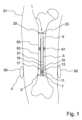
図1は、患者51の長骨を伸展させるための髄内釘1の模式の概観略図を示す。髄内釘1は、長骨内に配置され、ここで、髄内釘1の第1のチューブ3は、第1の骨断片53とロックされ、第2のチューブ5は第2の骨断片55とロックされる。第2のチューブ5は、第1のチューブ3に、互いの内部で軸方向に動くことが可能なように接続される。図1において、第2のチューブ5は、第1のチューブ3に部分的に導入され、第1のチューブ3に対して軸方向に動くことが可能である。Figure 1 shows a schematic overview of an
図1において、第1のチューブ3は、第2のチューブ5の反対側の第1のチューブ3の端部にある端部領域において、第1のロック開口7を有する。第1のロック手段9、図1ではボルトは、第1の骨断片43に導入され、第1のロック開口7を通って位置付けられる。In FIG. 1, the
第1のロック開口7と第2のチューブ5との間で、コイル領域において、コイル11が第1のチューブ3に配置される。第1のチューブ3はコイル領域において、具体的には、隣接する端部領域における、または第2のチューブ5の方向で軸方向にコイル領域に対して隣接する中間領域における第1のチューブ3の外径と比較して、より小さい直径を有する。コイル領域において、コイル11はコイルエンベロープ13によって取り囲まれている。図1において、コイルエンベロープ13は、コイル領域を半径方向に外側まで満たし、端部領域における第1のチューブ3の外径と同一平面であり、中間領域における第1のチューブ3の外径と同一平面である。Between the
図1において、コイル11は、円柱状コイルとして実現される。例えば図1において貫通コイルとして実現された一次コイル59は、患者51の体外に、具体的にはコイル11の周辺に配置される。電流をコイル11に誘起する交流磁場によって、エネルギを髄内釘1に、具体的にはコイル11に誘導的に移すために、交流磁場を提供するように一次コイル59は適合される。In FIG. 1, the
コイル領域と第2のチューブ5との間の中間領域に、第2のロック開口15が配置される。第2のロック手段17は、第1の骨断片53へと導入され、第2のロック開口15を通って位置付けられる。A second locking opening 15 is located in the intermediate region between the coil region and the
駆動部は、第2のチューブ5とコイル11との間に、図1においては例えば、第2のチューブ5と第2のロック開口15との間に配置される。典型的に、駆動部、図1においてはモータ19、具体的には電動モータ、およびギア21は、第1のチューブ3および第2のチューブ5を軸方向で互いに向けて動かすように適合される。図1において、長骨を伸展させるために、第2のチューブ5は第1のチューブ3からゆっくりと抜き出され、結果として、第1の骨断片53および第2の骨断片55は離され、長骨は伸長される。この場合、骨化帯57において新たな骨組織が成長し得る。図1において、コイル11を介して駆動部にエネルギが供給される。The drive is disposed between the
第2のチューブにおいて、さらなるロック開口23が、第1のチューブ3の反対側の第2のチューブ5の端部に配置される。さらなるロック手段25は、第2の骨断片55へと導入され、さらなるロック開口23を通って位置付けられる。さらなるロック手段25は、さらなるロック開口23を介して第2の骨断片55を第2のチューブ5とロックする。より明確にするために、ロック手段はさらなる図においては表示しなかった。In the second tube, a further locking
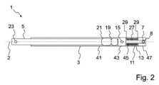
図2は、第1のチューブ3および第2のチューブ5を有する髄内釘1の模式側面図を示し、第1のチューブ3および第2のチューブ5は、髄内釘1の長軸2に沿って配置される。第2のチューブ5は、第1のチューブ3内に部分的に配置され、第1のチューブ3に対して軸方向に動かすことが可能である。第2のチューブ5、モータ19、およびギア21は、第1のチューブ3の中空ピース41中に配置される。第2のチューブ5の反対側の第1のチューブ3の端部での端部領域において、第1のチューブ3の端部ピース47が配置される。端部ピース47は、端部領域に隣接する第1のチューブ3のコイル領域から端部領域へと突出する、第1のチューブ3のマンドレル45を囲む。第1のロック開口7は金属スリーブ8を通って延在する。金属スリーブ8は、マンドレル45のマンドレル開口および端部ピース47の端部ピース開口を通って挿入される。マンドレル45のマンドレル開口および端部ピース47の端部ピース開口は、互いと位置合わせされるように配置される。金属スリーブ8は、端部ピース開口の周囲に沿って端部ピース47に溶接される。2 shows a schematic side view of an
さらなる例示的な実施形態において、マンドレルは、端部ピースに直接溶接されるか、接合されるか、または端部ピースに別の方法で接続される。In further exemplary embodiments, the mandrel is welded, bonded, or otherwise connected directly to the end piece.
コイル領域において、第1のチューブ3は、マンドレル45、およびマンドレル45の周りの外側に半径方向で配置されたコイルコア27を含む。マンドレル45は、マンドレル45に隣接する端部ピース47より、または中間ピース43より小さい外径を有し、中間ピースは、コイル領域および中空ピース41との間に配置される。図2において、マンドレル45および中間ピース43は金属で作製される。マンドレル45は、中間ピース43と一体で作製される。In the coil region, the
図2において、コイルコア27は、フェライトコアとして実現される。端部ピース47および中間ピース43それぞれの方向において軸方向に、コイルコア27は半径方向の突起部29を有する。コイル11は、コイルコア27の外側に半径方向で配置され、コイルコア27を包含する。図2において、コイル11は、円柱状コイルとして実現される。コイル11は、コイルコア27の半径方向の突起部29の間に配置される。In FIG. 2, the
コイルコア27の半径方向の突起部29は、具体的には、中間ピース43または端部ピース47などの隣接するチューブピースが金属でできている場合に有利である。コイルコア27は、コイル11、具体的にはコイル11の巻き線、またはコイルコア27を通る磁束を、隣接するチューブピースから遮蔽することができる。The
コイルコア27およびコイル11は、半径方向に外側に向かってコイルエンベロープ13によって取り囲まれている。コイルエンベロープ13は、第1のチューブ3のコイル領域をプラスチック材料で鋳造することによって作製される。The
図2において、中間ピース43は、第2のロック開口15を有する。中間ピース43は、第2のチューブ5に向いている軸方向の突出部を含み、突出部は中空ピース41と噛み合う。中空ピース41は、中間ピース43と半径方向に一緒に溶接される。中間ピース43は軸方向の穴を有し、軸方向の穴を通ってコイル11とモータ19との間の電気接続が誘導される。さらなる例示的な実施形態において、穴は、部分的にまたは完全に円形になるように実現される。In FIG. 2, the
図3は、髄内釘1のさらなる実施形態の詳細を示す。図3において、第1のチューブ3のマンドレル45は、第1のチューブ3の端部ピース47と溶接され、端部ピース47へと少なくとも実質的に突出しない。典型的に、マンドレル45は、正面で端部ピース47と溶接される。第1のロック開口7は、マンドレル45を通って延在しない。中間ピース43は、マンドレル45と一体で実現される。Figure 3 shows details of a further embodiment of the
図4Aにおいて、髄内釘1の第1のチューブは、第1のチューブ3の端部領域における第1のロック開口7および第1のチューブの中間ピース43における第2のロック開口15だけでなく、第1のロック開口7とコイル領域との間に、第3のロック開口31を有する。In FIG. 4A, the first tube of the
図4Bは、図4Aと同様であるが、中間ピース43における第2のロック開口15を有しない実施形態を示す。図4Aおよび図4Bにおいて、第1のロック開口7および第3のロック開口31は、端部ピース47およびマンドレル45を通って延在する。さらなる実施形態において、図3と同様であるマンドレル45は、端部ピース47へと短く突出してもよく、まったく突出しなくてもよく、第1のロック開口7または第3のロック開口31は、マンドレル45によって実現されなくてもよい。Figure 4B shows an embodiment similar to Figure 4A but without the second locking opening 15 in the
図5Aおよび図5Bは、互いに対してねじれたロック開口、または髄内釘1の長軸2に対して斜めに方向付けられたロック開口を有する髄内釘1を示す。図5Aにおいて、第1のロック開口7および第2のロック開口15は、異なる半径方向に方向付けられる。図5Bにおいて、第1のロック開口7および第2のロック開口15は、髄内釘1の長軸2に対して斜めに方向付けられる。図5Bにおいて、第1のロック開口7および第2のロック開口15は、交差の共通点に向かって方向付けられる。5A and 5B show an
図6は、多部品端部ピース47を有する髄内釘1のさらなる実施形態を示す。端部ピース47は、第1の端部ピース33、第2の端部ピース35、およびネジ山インサート37を含む。図6において、第1の端部ピース33は、金属スリーブとして実現される。第1の端部ピース33は、マンドレル45のマンドレル開口46を通して挿入される。第1のロック開口7は、端部ピース33を通って延在する。図6において、第1のロック開口7および第2のロック開口15は、図6の表示面に方向付けられる。マンドレル45は、第1の端部ピース33を包含し、第2の端部ピース35へと突出する。中間ピース43は、マンドレル45と一体で作製される。コイルエンベロープ13および第2の端部ピース35は、中間ピース43をオーバーモールド成形することによって、具体的には、中間ピース43、マンドレル45、コイルコア27、コイル11、第1の端部ピース33、およびネジ山インサート37の軸方向部分に沿って、生体適合性プラスチック材料を用いて射出成形で作製される。Figure 6 shows a further embodiment of the
さらなる例示的な実施形態において、ネジ山インサートは存在しない。そのような例示的な実施形態において、ネジ山インサートは、後でプラスチック材料へと導入される、具体的にはねじ込まれる。In a further exemplary embodiment, the thread insert is not present. In such an exemplary embodiment, the thread insert is later introduced, specifically screwed, into the plastic material.
図6において、第1のピースの中間ピース43は、コイル領域に向いている半径方向の凹部44を有する。コイルエンベロープ13は、半径方向の凹部44へと軸方向に延在する。半径方向の凹部において、第1のチューブおよびコイルエンベロープ13は、形状にぴったり合う様式で接続される。In FIG. 6, the first piece
図7は、中間ピース43に向いている半径方向のフィレット39を有するマンドレル45を有する髄内釘1の模式断面図を示す。半径方向のフィレット39は、マンドレル45と中間ピース43との間での、具体的には第1のロック開口(例示されない)と第2のロック開口15との間での曲げ荷重の伝達を向上するために有利であり得る。中間ピース43の方向において、コイルコア27は軸方向に、フィレット39に一致する凹部を有する。具体的にはコイルコア27における一致した凹部を有する、半径方向のフィレット39は、図7の例示的な実施形態に制限されないが、図1~図6の例示的な実施形態においても実現されてもよい。Figure 7 shows a schematic cross-sectional view of an
本発明は、上述の例示的な実施形態に制限されず、本発明の範囲はむしろ、特許請求の範囲によって決定される。具体的には、例示される部品の必ずしもすべてが本発明の特徴というわけではなく、これは特に例示されたヒトの骨に当てはまる。
[項目1]
-前記髄内釘(1)の軸方向に延在する第1のチューブ(3)と、
-前記第1のチューブ(3)と互いの内部で軸方向に動くことが可能なように連結された、前記髄内釘(1)の軸方向に延在する第2のチューブ(5)と、
-前記第2のチューブ(5)から反対に向いた前記第1のチューブ(3)の端部領域にある第1のロック開口(7)と、
-前記第1のロック開口(7)と前記第2のチューブ(5)との間で前記第1のチューブ(3)のコイル領域に配されたコイル(11)と
を備える、長骨を伸展させるための髄内釘(1)。
[項目2]
前記第1のチューブ(3)は、前記コイル領域においてより小さい外径を有し、前記コイル(11)は、前記コイル領域において前記第1のチューブ(3)上の外側に半径方向に配置された、請求項1に記載の髄内釘(1)。
[項目3]
コイルエンベロープ(13)は、前記コイル(11)を取り囲み、前記コイルエンベロープ(13)は少なくとも実質的に、非金属材料で構成された、前述の請求項のいずれか一項に記載の髄内釘(1)。
[項目4]
前記コイルエンベロープ(13)は、前記第1のチューブ(3)上に配置された前記コイル(11)をプラスチック材料でオーバーキャスト成形またはオーバーモールド成形することによって作製される、前述の請求項のいずれか一項に記載の髄内釘(1)。
[項目5]
前記コイルエンベロープ(13)は、前記コイル領域を、少なくとも実質的に半径方向に、前記第1のチューブ(3)の外輪郭と同一平面の様式で前記外側まで満たす、前述の請求項のいずれか一項に記載の髄内釘(1)。
[項目6]
前記コイル(11)は円柱状コイルであり、前記髄内釘(1)と同軸に配置される、前述の請求項のいずれか一項に記載の髄内釘(1)。
[項目7]
前記第1のチューブ(3)は、前記コイル(11)の内側に半径方向に配置されたコイルコア(27)を含む、前述の請求項のいずれか一項に記載の髄内釘(1)。
[項目8]
前記コイルコア(27)は、前記コイル(11)の軸方向端に半径方向の突起部(29)を有する、前述の請求項のいずれか一項に記載の髄内釘(1)。
[項目9]
前記第1のチューブ(3)は少なくとも2つの相互接続されたチューブピースで作製された、前述の請求項のいずれか一項に記載の髄内釘(1)。
[項目10]
前記第1のチューブ(3)は、前記コイル領域において、少なくとも実質的に満ちているように実現される、前述の請求項のいずれか一項に記載の髄内釘(1)。
[項目11]
前記第1のチューブ(3)は、前記コイル領域と前記第2のチューブ(5)との間の中間領域において第2のロック開口(15)を有する、前述の請求項のいずれか一項に記載の髄内釘(1)。
[項目12]
前記第1のロック開口(7)と前記第2のロック開口(15)との間の距離は、最大30mm、具体的には最大25mmになる、請求項11に記載の髄内釘(1)。
[項目13]
前記コイル(11)に電気接続された駆動部を備える、前述の請求項のいずれか一項に記載の髄内釘(1)。
[項目14]
前記コイル領域における前記第1のチューブ(3)の前記外径は、前記第1のロック開口(7)の直径より、および/または前記第2のロック開口(15)の直径より大きい、前述の請求項のいずれか一項に記載の髄内釘(1)。
[項目15]
一次コイル(59)から、前述の請求項のいずれか一項に記載の髄内釘(1)のコイル(11)にエネルギを伝達するための方法であって、
-前記一次コイル(59)を通電する段階と、
-前記一次コイル(59)を通電することによって放出された前記電磁エネルギの少なくとも一部を、前記髄内釘(1)の前記コイル(11)によって受け取る段階と
を含む方法。 The present invention is not limited to the exemplary embodiments described above, the scope of the invention being determined instead by the claims. In particular, not all of the illustrated parts are characteristic of the present invention, and this is particularly true for the illustrated human bone.
[Item 1]
a first tube (3) extending axially of the nail (1);
a second tube (5) extending in the axial direction of the nail (1) and connected to the first tube (3) so as to be axially movable inside each other;
a first locking opening (7) in the end region of the first tube (3) facing away from the second tube (5);
- a coil (11) arranged in the coil region of the first tube (3) between the first locking opening (7) and the second tube (5).
[Item 2]
2. The intramedullary nail (1) according to
[Item 3]
10. The nail (1) according to any one of the previous claims, wherein a coil envelope (13) surrounds said coil (11), said coil envelope (13) being at least substantially composed of a non-metallic material.
[Item 4]
The nail (1) according to any one of the previous claims, wherein the coil envelope (13) is made by overcasting or overmolding the coil (11) placed on the first tube (3) with a plastic material.
[Item 5]
10. The nail (1) according to any one of the previous claims, wherein the coil envelope (13) fills the coil region at least substantially radially to the outside in a flush manner with the outer contour of the first tube (3).
[Item 6]
The intramedullary nail (1) according to any one of the previous claims, wherein the coil (11) is a cylindrical coil and is arranged coaxially with the intramedullary nail (1).
[Item 7]
The intramedullary nail (1) according to any one of the previous claims, wherein the first tube (3) comprises a coil core (27) arranged radially inside the coil (11).
[Item 8]
The nail (1) according to any one of the previous claims, wherein the coil core (27) has radial projections (29) at the axial ends of the coil (11).
[Item 9]
The intramedullary nail (1) according to any one of the previous claims, wherein the first tube (3) is made of at least two interconnected tube pieces.
[Item 10]
10. The nail (1) according to any one of the previous claims, wherein said first tube (3) is realised to be at least substantially full in said coil area.
[Item 11]
The nail (1) according to any one of the previous claims, wherein the first tube (3) has a second locking opening (15) in an intermediate region between the coil region and the second tube (5).
[Item 12]
The nail (1) according to
[Item 13]
10. The nail (1) according to any one of the previous claims, comprising a drive unit electrically connected to said coil (11).
[Item 14]
The nail (1) according to any one of the previous claims, wherein the outer diameter of the first tube (3) in the coil region is greater than the diameter of the first locking opening (7) and/or greater than the diameter of the second locking opening (15).
[Item 15]
A method for transmitting energy from a primary coil (59) to a coil (11) of an intramedullary nail (1) according to any one of the previous claims, comprising:
- energizing the primary coil (59);
receiving at least a portion of the electromagnetic energy emitted by energizing the primary coil (59) by the coil (11) of the nail (1).
Claims (12)
Translated fromJapanese-前記髄内釘の軸方向に延在する第1のチューブと、
-前記第1のチューブと互いの内部で軸方向に動くことが可能なように連結された、前記髄内釘の軸方向に延在する第2のチューブと、
-前記第2のチューブから反対に向いた前記第1のチューブの端部領域にある、前記長骨の骨断片において前記髄内釘をロックするための第1のロック開口と、
-前記第1のロック開口と前記第2のチューブとの間で前記第1のチューブのコイル領域に配されたコイルと、
-前記コイルに電気的に接続された駆動部と
を備え、
-前記第1のチューブは、前記コイル領域においてより小さい外径を有し、前記コイルは、前記コイル領域において前記第1のチューブ上の外側に半径方向に配置された、
髄内釘。 1. An intramedullary nail for lengthening a long bone,comprising :
a first tube extending axiallyof the nail;
a second tube extending in the axial directionof the nail, connectedto the first tubeso that they can move axially inside each other;
a first lockingopening in the end regionof the first tube facing awayfrom the second tube for locking the intramedullary nail in a bone fragment of the long bone;
a coil arranged in the coil regionof the first tubebetween the first locking openingand the second tube;
a drive unit electrically connectedto said coil,
- the firsttube has a smaller outer diameter in the coil region, and thecoil is disposed radially outwardon the first tube in the coil region;
Intramedullary nail.
Applications Claiming Priority (3)
| Application Number | Priority Date | Filing Date | Title |
|---|---|---|---|
| DE102019122354.7ADE102019122354A1 (en) | 2019-08-20 | 2019-08-20 | Intramedullary nail for distraction of a long bone |
| DE102019122354.7 | 2019-08-20 | ||
| PCT/EP2020/073302WO2021032823A1 (en) | 2019-08-20 | 2020-08-20 | Intramedullary nail for distracting a long bone |
Publications (2)
| Publication Number | Publication Date |
|---|---|
| JP2022545338A JP2022545338A (en) | 2022-10-27 |
| JP7533899B2true JP7533899B2 (en) | 2024-08-14 |
Family
ID=72193437
Family Applications (1)
| Application Number | Title | Priority Date | Filing Date |
|---|---|---|---|
| JP2022506445AActiveJP7533899B2 (en) | 2019-08-20 | 2020-08-20 | Intramedullary nails for lengthening long bones |
Country Status (11)
| Country | Link |
|---|---|
| US (1) | US12324612B2 (en) |
| EP (1) | EP4017387B1 (en) |
| JP (1) | JP7533899B2 (en) |
| CN (1) | CN114340527B (en) |
| BR (1) | BR112022003086A2 (en) |
| CA (1) | CA3148724A1 (en) |
| DE (1) | DE102019122354A1 (en) |
| ES (1) | ES2941883T3 (en) |
| IL (1) | IL290243B1 (en) |
| WO (1) | WO2021032823A1 (en) |
| ZA (1) | ZA202201366B (en) |
Families Citing this family (3)
| Publication number | Priority date | Publication date | Assignee | Title |
|---|---|---|---|---|
| EP4529869A1 (en) | 2023-09-28 | 2025-04-02 | Orthofix S.r.l. | Intramedullary nail for a long bone |
| WO2025083150A1 (en) | 2023-10-19 | 2025-04-24 | Orthofix S.R.L. | Motorized and improved intramedullary nail for bone lengthening or transport |
| WO2025093360A1 (en) | 2023-10-31 | 2025-05-08 | Orthofix S.R.L. | Motorized intramedullary nail for bone lengthening or transport |
Citations (4)
| Publication number | Priority date | Publication date | Assignee | Title |
|---|---|---|---|---|
| JP2004526544A (en) | 2001-05-23 | 2004-09-02 | オーソゴン テクノロジーズ 2003 リミテッド | Magnetically driven intramedullary device |
| US20050010233A1 (en) | 2001-11-19 | 2005-01-13 | Manfred Wittenstein | Distraction device |
| JP2009254804A (en) | 2008-03-24 | 2009-11-05 | Japan Medical Materials Corp | In vivo actuator and bone adjustment apparatus |
| US20170172624A1 (en) | 2014-03-06 | 2017-06-22 | Mps Micro Precision Systems Ag | Implantable device |
Family Cites Families (22)
| Publication number | Priority date | Publication date | Assignee | Title |
|---|---|---|---|---|
| US5415660A (en)* | 1994-01-07 | 1995-05-16 | Regents Of The University Of Minnesota | Implantable limb lengthening nail driven by a shape memory alloy |
| DE19700225A1 (en)* | 1997-01-07 | 1998-07-09 | Augustin Prof Dr Betz | Distraction device for moving two parts of a bone apart |
| US6033412A (en)* | 1997-04-03 | 2000-03-07 | Losken; H. Wolfgang | Automated implantable bone distractor for incremental bone adjustment |
| DE19906423A1 (en)* | 1999-02-16 | 2000-08-17 | Wittenstein Gmbh & Co Kg | Active marrow spike for drawing out sections of bone consists of two elements moving against each other and electrically operated driving element to supply spike with electrical energy via detachable plug-in element. |
| DE19908851A1 (en)* | 1999-03-01 | 2000-09-07 | Rainer Baumgart | Intramedullary nail for bone distraction |
| FR2843875B1 (en)* | 2002-08-30 | 2004-10-08 | Arnaud Andre Soubeiran | IMPLANTABLE DEVICE FOR TRANSFORMING ON DEMAND ALTERNATE COUPLES APPLIED BY MUSCLE FORCE BETWEEN TWO WORKPIECES IN A MOVEMENT OF TWO BODIES RELATIVELY TO ONE ANOTHER |
| DE10340025A1 (en)* | 2003-08-28 | 2005-03-24 | Wittenstein Ag | Surgical device for bone extension, comprising planetary gear acting on outer sleeve serving as ring gear |
| US7955357B2 (en)* | 2004-07-02 | 2011-06-07 | Ellipse Technologies, Inc. | Expandable rod system to treat scoliosis and method of using the same |
| DE102006018191B4 (en)* | 2006-04-19 | 2008-08-07 | Neue Magnetodyn Gmbh | Electric intramedullary nail system |
| US7753915B1 (en)* | 2007-06-14 | 2010-07-13 | August Eksler | Bi-directional bone length adjustment system |
| WO2010134078A1 (en)* | 2009-05-18 | 2010-11-25 | Orthogon Technologies 2003 | An intramedullary nail device |
| JP5751642B2 (en)* | 2009-09-04 | 2015-07-22 | エリプス テクノロジーズ, インク.Ellipse Technologies, Inc. | Bone growth apparatus and method |
| CN102917659B (en)* | 2010-03-19 | 2016-04-20 | 史密夫和内修有限公司 | Telescoping Intramedullary Nails and Actuation Mechanisms |
| WO2012051512A1 (en)* | 2010-10-14 | 2012-04-19 | Virginia Tech Intellectual Properties, Inc. | Intramedullary nail targeting device |
| US9308089B2 (en)* | 2011-06-27 | 2016-04-12 | University Of Cape Town | Endoprosthesis |
| DE102011053638A1 (en)* | 2011-09-15 | 2013-03-21 | Wittenstein Ag | Mark Nagel |
| US20130165733A1 (en)* | 2011-12-27 | 2013-06-27 | Richard A. Rogachefsky | Orthopedic fixation device with magnetic field generator |
| ES2755650T3 (en)* | 2014-10-17 | 2020-04-23 | Synoste Oy | Device with a receiving antenna and related power transfer system |
| KR102588501B1 (en)* | 2014-10-23 | 2023-10-11 | 누베이시브 스페셜라이즈드 오소페딕스, 인크. | Remotely adjustable interactive bone reshaping implant |
| DE102015109624A1 (en)* | 2015-06-16 | 2016-12-22 | Wittenstein Se | Mechatronic implant |
| BR112018015504A2 (en)* | 2016-01-28 | 2018-12-18 | Nuvasive Specialized Orthopedics, Inc. | bone transport systems |
| CN108143477B (en)* | 2017-12-18 | 2020-05-19 | 武汉大学 | Intramedullary bone lengthening device using memory alloy spring electromagnetic heating |
- 2019
- 2019-08-20DEDE102019122354.7Apatent/DE102019122354A1/enactivePending
- 2020
- 2020-08-20BRBR112022003086Apatent/BR112022003086A2/enunknown
- 2020-08-20ESES20760803Tpatent/ES2941883T3/enactiveActive
- 2020-08-20CACA3148724Apatent/CA3148724A1/enactivePending
- 2020-08-20USUS17/636,076patent/US12324612B2/enactiveActive
- 2020-08-20JPJP2022506445Apatent/JP7533899B2/enactiveActive
- 2020-08-20EPEP20760803.5Apatent/EP4017387B1/enactiveActive
- 2020-08-20WOPCT/EP2020/073302patent/WO2021032823A1/ennot_activeCeased
- 2020-08-20CNCN202080058348.XApatent/CN114340527B/enactiveActive
- 2022
- 2022-01-28ZAZA2022/01366Apatent/ZA202201366B/enunknown
- 2022-01-30ILIL290243Apatent/IL290243B1/enunknown
Patent Citations (4)
| Publication number | Priority date | Publication date | Assignee | Title |
|---|---|---|---|---|
| JP2004526544A (en) | 2001-05-23 | 2004-09-02 | オーソゴン テクノロジーズ 2003 リミテッド | Magnetically driven intramedullary device |
| US20050010233A1 (en) | 2001-11-19 | 2005-01-13 | Manfred Wittenstein | Distraction device |
| JP2009254804A (en) | 2008-03-24 | 2009-11-05 | Japan Medical Materials Corp | In vivo actuator and bone adjustment apparatus |
| US20170172624A1 (en) | 2014-03-06 | 2017-06-22 | Mps Micro Precision Systems Ag | Implantable device |
Also Published As
| Publication number | Publication date |
|---|---|
| ES2941883T3 (en) | 2023-05-26 |
| US12324612B2 (en) | 2025-06-10 |
| BR112022003086A2 (en) | 2022-05-17 |
| US20220287745A1 (en) | 2022-09-15 |
| EP4017387B1 (en) | 2023-02-08 |
| EP4017387A1 (en) | 2022-06-29 |
| JP2022545338A (en) | 2022-10-27 |
| CN114340527A (en) | 2022-04-12 |
| CN114340527B (en) | 2025-02-11 |
| CA3148724A1 (en) | 2021-02-25 |
| ZA202201366B (en) | 2022-09-28 |
| IL290243A (en) | 2022-03-01 |
| DE102019122354A1 (en) | 2021-02-25 |
| IL290243B1 (en) | 2025-07-01 |
| WO2021032823A1 (en) | 2021-02-25 |
Similar Documents
| Publication | Publication Date | Title |
|---|---|---|
| JP7533899B2 (en) | Intramedullary nails for lengthening long bones | |
| US9138266B2 (en) | Intramedullary nail | |
| US6708065B2 (en) | Antenna for an implantable medical device | |
| CN101431956B (en) | Electrical Intramedullary Nail System | |
| JP2017205561A (en) | Orthopedic fixation device with magnetic field generator | |
| US20220409221A1 (en) | Intramedullary nail with wire or magnet for targeting of a bone-anchor locking hole | |
| US6383185B1 (en) | Medullary nail for the distraction of bones | |
| EP1854503B1 (en) | Stimulation of the osteogenesis of a traumatized bone being fixed by means of a bone stabilizing implant | |
| KR20140010358A (en) | Intramedullary nail | |
| EP2142122A1 (en) | Implant devices constructed with metallic and polymeric components | |
| CA2447155A1 (en) | Magnetically-actuable intramedullary device | |
| EP2342724B1 (en) | Reuse of screw thread | |
| CN101557766A (en) | Fixing element for a bone fragment | |
| WO2013032808A1 (en) | Implant devices constructed with metallic and polymeric components | |
| EP3710106B1 (en) | Pulsed electromagnetic field therapy device | |
| JP7376512B2 (en) | electrical stimulation implant | |
| CN103961171B (en) | Bone screws | |
| US20190308014A1 (en) | Bipolar Bone Anchor With Connection For Electrostimulation | |
| Mispelter et al. | Optimization of 13C-{1H} double coplanar surface-coil design for the WALTZ-16 decoupling sequence | |
| US20200316388A1 (en) | Electrical Stimulation Screws | |
| EP4529869A1 (en) | Intramedullary nail for a long bone |
Legal Events
| Date | Code | Title | Description |
|---|---|---|---|
| A621 | Written request for application examination | Free format text:JAPANESE INTERMEDIATE CODE: A621 Effective date:20230804 | |
| A977 | Report on retrieval | Free format text:JAPANESE INTERMEDIATE CODE: A971007 Effective date:20240306 | |
| A131 | Notification of reasons for refusal | Free format text:JAPANESE INTERMEDIATE CODE: A131 Effective date:20240319 | |
| A521 | Request for written amendment filed | Free format text:JAPANESE INTERMEDIATE CODE: A523 Effective date:20240605 | |
| TRDD | Decision of grant or rejection written | ||
| A01 | Written decision to grant a patent or to grant a registration (utility model) | Free format text:JAPANESE INTERMEDIATE CODE: A01 Effective date:20240702 | |
| A61 | First payment of annual fees (during grant procedure) | Free format text:JAPANESE INTERMEDIATE CODE: A61 Effective date:20240724 | |
| R150 | Certificate of patent or registration of utility model | Ref document number:7533899 Country of ref document:JP Free format text:JAPANESE INTERMEDIATE CODE: R150 |