JP7531505B2 - Valve stopper for a medical injection device and medical injection device for injecting at least one composition - Patents.com - Google Patents
Valve stopper for a medical injection device and medical injection device for injecting at least one composition - Patents.comDownload PDFInfo
- Publication number
- JP7531505B2 JP7531505B2JP2021549995AJP2021549995AJP7531505B2JP 7531505 B2JP7531505 B2JP 7531505B2JP 2021549995 AJP2021549995 AJP 2021549995AJP 2021549995 AJP2021549995 AJP 2021549995AJP 7531505 B2JP7531505 B2JP 7531505B2
- Authority
- JP
- Japan
- Prior art keywords
- valve stopper
- membrane
- valve
- composition
- barrel
- Prior art date
- Legal status (The legal status is an assumption and is not a legal conclusion. Google has not performed a legal analysis and makes no representation as to the accuracy of the status listed.)
- Active
Links
Images


Classifications
- A—HUMAN NECESSITIES
- A61—MEDICAL OR VETERINARY SCIENCE; HYGIENE
- A61M—DEVICES FOR INTRODUCING MEDIA INTO, OR ONTO, THE BODY; DEVICES FOR TRANSDUCING BODY MEDIA OR FOR TAKING MEDIA FROM THE BODY; DEVICES FOR PRODUCING OR ENDING SLEEP OR STUPOR
- A61M39/00—Tubes, tube connectors, tube couplings, valves, access sites or the like, specially adapted for medical use
- A61M39/22—Valves or arrangement of valves
- A61M39/24—Check- or non-return valves
- A—HUMAN NECESSITIES
- A61—MEDICAL OR VETERINARY SCIENCE; HYGIENE
- A61M—DEVICES FOR INTRODUCING MEDIA INTO, OR ONTO, THE BODY; DEVICES FOR TRANSDUCING BODY MEDIA OR FOR TAKING MEDIA FROM THE BODY; DEVICES FOR PRODUCING OR ENDING SLEEP OR STUPOR
- A61M5/00—Devices for bringing media into the body in a subcutaneous, intra-vascular or intramuscular way; Accessories therefor, e.g. filling or cleaning devices, arm-rests
- A61M5/178—Syringes
- A61M5/19—Syringes having more than one chamber, e.g. including a manifold coupling two parallelly aligned syringes through separate channels to a common discharge assembly
- A—HUMAN NECESSITIES
- A61—MEDICAL OR VETERINARY SCIENCE; HYGIENE
- A61M—DEVICES FOR INTRODUCING MEDIA INTO, OR ONTO, THE BODY; DEVICES FOR TRANSDUCING BODY MEDIA OR FOR TAKING MEDIA FROM THE BODY; DEVICES FOR PRODUCING OR ENDING SLEEP OR STUPOR
- A61M5/00—Devices for bringing media into the body in a subcutaneous, intra-vascular or intramuscular way; Accessories therefor, e.g. filling or cleaning devices, arm-rests
- A61M5/178—Syringes
- A61M5/28—Syringe ampoules or carpules, i.e. ampoules or carpules provided with a needle
- A61M5/285—Syringe ampoules or carpules, i.e. ampoules or carpules provided with a needle with sealing means to be broken or opened
- A61M5/286—Syringe ampoules or carpules, i.e. ampoules or carpules provided with a needle with sealing means to be broken or opened upon internal pressure increase, e.g. pierced or burst
- A—HUMAN NECESSITIES
- A61—MEDICAL OR VETERINARY SCIENCE; HYGIENE
- A61M—DEVICES FOR INTRODUCING MEDIA INTO, OR ONTO, THE BODY; DEVICES FOR TRANSDUCING BODY MEDIA OR FOR TAKING MEDIA FROM THE BODY; DEVICES FOR PRODUCING OR ENDING SLEEP OR STUPOR
- A61M5/00—Devices for bringing media into the body in a subcutaneous, intra-vascular or intramuscular way; Accessories therefor, e.g. filling or cleaning devices, arm-rests
- A61M5/178—Syringes
- A61M5/31—Details
- A61M5/315—Pistons; Piston-rods; Guiding, blocking or restricting the movement of the rod or piston; Appliances on the rod for facilitating dosing ; Dosing mechanisms
- A61M5/31511—Piston or piston-rod constructions, e.g. connection of piston with piston-rod
- A61M5/31513—Piston constructions to improve sealing or sliding
- A—HUMAN NECESSITIES
- A61—MEDICAL OR VETERINARY SCIENCE; HYGIENE
- A61M—DEVICES FOR INTRODUCING MEDIA INTO, OR ONTO, THE BODY; DEVICES FOR TRANSDUCING BODY MEDIA OR FOR TAKING MEDIA FROM THE BODY; DEVICES FOR PRODUCING OR ENDING SLEEP OR STUPOR
- A61M5/00—Devices for bringing media into the body in a subcutaneous, intra-vascular or intramuscular way; Accessories therefor, e.g. filling or cleaning devices, arm-rests
- A61M5/178—Syringes
- A61M5/31—Details
- A61M5/315—Pistons; Piston-rods; Guiding, blocking or restricting the movement of the rod or piston; Appliances on the rod for facilitating dosing ; Dosing mechanisms
- A61M5/31596—Pistons; Piston-rods; Guiding, blocking or restricting the movement of the rod or piston; Appliances on the rod for facilitating dosing ; Dosing mechanisms comprising means for injection of two or more media, e.g. by mixing
- A—HUMAN NECESSITIES
- A61—MEDICAL OR VETERINARY SCIENCE; HYGIENE
- A61M—DEVICES FOR INTRODUCING MEDIA INTO, OR ONTO, THE BODY; DEVICES FOR TRANSDUCING BODY MEDIA OR FOR TAKING MEDIA FROM THE BODY; DEVICES FOR PRODUCING OR ENDING SLEEP OR STUPOR
- A61M5/00—Devices for bringing media into the body in a subcutaneous, intra-vascular or intramuscular way; Accessories therefor, e.g. filling or cleaning devices, arm-rests
- A61M5/178—Syringes
- A61M2005/1787—Syringes for sequential delivery of fluids, e.g. first medicament and then flushing liquid
- A—HUMAN NECESSITIES
- A61—MEDICAL OR VETERINARY SCIENCE; HYGIENE
- A61M—DEVICES FOR INTRODUCING MEDIA INTO, OR ONTO, THE BODY; DEVICES FOR TRANSDUCING BODY MEDIA OR FOR TAKING MEDIA FROM THE BODY; DEVICES FOR PRODUCING OR ENDING SLEEP OR STUPOR
- A61M5/00—Devices for bringing media into the body in a subcutaneous, intra-vascular or intramuscular way; Accessories therefor, e.g. filling or cleaning devices, arm-rests
- A61M5/178—Syringes
- A61M5/31—Details
- A61M2005/3128—Incorporating one-way valves, e.g. pressure-relief or non-return valves
- A—HUMAN NECESSITIES
- A61—MEDICAL OR VETERINARY SCIENCE; HYGIENE
- A61M—DEVICES FOR INTRODUCING MEDIA INTO, OR ONTO, THE BODY; DEVICES FOR TRANSDUCING BODY MEDIA OR FOR TAKING MEDIA FROM THE BODY; DEVICES FOR PRODUCING OR ENDING SLEEP OR STUPOR
- A61M39/00—Tubes, tube connectors, tube couplings, valves, access sites or the like, specially adapted for medical use
- A61M39/22—Valves or arrangement of valves
- A61M39/24—Check- or non-return valves
- A61M2039/2426—Slit valve
- A—HUMAN NECESSITIES
- A61—MEDICAL OR VETERINARY SCIENCE; HYGIENE
- A61M—DEVICES FOR INTRODUCING MEDIA INTO, OR ONTO, THE BODY; DEVICES FOR TRANSDUCING BODY MEDIA OR FOR TAKING MEDIA FROM THE BODY; DEVICES FOR PRODUCING OR ENDING SLEEP OR STUPOR
- A61M5/00—Devices for bringing media into the body in a subcutaneous, intra-vascular or intramuscular way; Accessories therefor, e.g. filling or cleaning devices, arm-rests
- A61M5/178—Syringes
- A61M5/28—Syringe ampoules or carpules, i.e. ampoules or carpules provided with a needle
- A61M5/284—Syringe ampoules or carpules, i.e. ampoules or carpules provided with a needle comprising means for injection of two or more media, e.g. by mixing
Landscapes
- Health & Medical Sciences (AREA)
- Heart & Thoracic Surgery (AREA)
- Hematology (AREA)
- Engineering & Computer Science (AREA)
- Anesthesiology (AREA)
- Biomedical Technology (AREA)
- Life Sciences & Earth Sciences (AREA)
- Animal Behavior & Ethology (AREA)
- General Health & Medical Sciences (AREA)
- Public Health (AREA)
- Veterinary Medicine (AREA)
- Vascular Medicine (AREA)
- Pulmonology (AREA)
- Infusion, Injection, And Reservoir Apparatuses (AREA)
Description
Translated fromJapanese本発明は、少なくとも1つの組成物を注入するための、医療用注入装置用のバルブストッパー、および前記バルブストッパーを含む医療用注入装置に関する。The present invention relates to a valve stopper for a medical injection device for injecting at least one composition, and to a medical injection device including said valve stopper.
事前に充填された注入装置は、薬剤またはワクチンを患者に送達するための一般的な容器であり、シリンジ、カートリッジ、および自動注入器などが含まれる。それらは通常、容器に滑り係合するプランジャーストッパーを含み、容器は、開業医が患者にすぐに使用できる注入装置を提供するために医薬組成物で満たされている。Pre-filled injection devices are common containers for delivering medications or vaccines to patients and include syringes, cartridges, and autoinjectors. They usually include a plunger stopper that slidingly engages the container, which is filled with the pharmaceutical composition to provide the practitioner with a ready-to-use injection device for the patient.
容器は、実質的に円筒形状を含み、プランジャーストッパーによって栓をすることができる近位端と、医薬組成物が容器から放出される遠位端と、および容器の近位端と遠位端との間に延びる側壁とを含む。実際には、プランジャーストッパーは、プランジャーによって加えられた圧力に応じて、容器の近位端から容器の遠位端に向かって移動し、それにより、容器内に含まれる薬剤を放出することを目的とする。The container comprises a substantially cylindrical shape, a proximal end that can be stoppered by a plunger stopper, a distal end at which the pharmaceutical composition is released from the container, and a sidewall extending between the proximal and distal ends of the container. In practice, the plunger stopper is intended to move from the proximal end of the container toward the distal end of the container in response to pressure exerted by the plunger, thereby releasing the medicament contained within the container.
患者の身体への注入の直前にバイアルに保管された医薬組成物で満たされた空の注入装置と比較すると、事前充填された注入装置の使用はいくつかの利点をもたらす。特に、注入前の準備を制限することにより、事前に充填された注入装置は、医療投薬エラーの削減、微生物汚染のリスクの最小化、および開業医のための使用の利便性の向上を提供する。さらに、そのような事前に充填された容器は、患者による自己投与を促進および単純化し得、これにより、治療のコストを削減し、患者のアドヒアランスを増加させることができる。最後に、事前に充填された注入装置は、医薬組成物がバイアルから事前に充填されていない注入装置に移されるときに通常発生する貴重な医薬組成物の損失を減らす。これにより、医薬組成物の所定の製造バッチで注入可能な注入の数が増え、購入とサプライチェーンのコストが削減される。Compared to empty infusion devices filled with pharmaceutical compositions stored in vials immediately prior to injection into the patient's body, the use of prefilled infusion devices offers several advantages. In particular, by limiting preparation prior to injection, prefilled infusion devices offer a reduction in medical dosing errors, a minimized risk of microbial contamination, and increased convenience of use for the practitioner. In addition, such prefilled containers may facilitate and simplify self-administration by patients, which can reduce the cost of treatment and increase patient adherence. Finally, prefilled infusion devices reduce the loss of valuable pharmaceutical composition that typically occurs when the pharmaceutical composition is transferred from a vial to a non-prefilled infusion device. This increases the number of injectable infusions possible in a given manufacturing batch of pharmaceutical composition, reducing purchasing and supply chain costs.
事前に充填された注入装置を使用して、患者への複数の組成物の注入を実行することができる。そのような場合、容器は、第1の組成物を含むように適合された第1のチャンバーおよび第2の組成物を含むように適合された第2のチャンバーを含む2つのチャンバーを含む。2つのチャンバーは、通常、プラグまたはダイヤフラムと呼ばれる第2のストッパーによって分離されており、これは、組成物が一方のチャンバーから他方のチャンバーに移動して混合するのを防ぐ。Pre-filled injection devices can be used to carry out injections of multiple compositions into a patient. In such cases, the container includes two chambers, including a first chamber adapted to contain a first composition and a second chamber adapted to contain a second composition. The two chambers are usually separated by a second stopper, called a plug or diaphragm, which prevents the compositions from migrating from one chamber to the other and mixing.
特許文献1は、異なる特性を有する2つの粘弾性溶液を分配するための装置を開示している。この装置は、それぞれが溶液を含む2つのチャンバーを分離する可動ダイヤフラムを備えている。可動ダイヤフラムは、第1の溶液が注入される前に2つの溶液の混合を防ぐのに十分であると同時に、第2の溶液のその後の注入を可能にする小さな直径の開口部を備えている。あるいは、可動ダイヤフラムは、第1の溶液を注入する前の2つの溶液の混合をさらに確実に防止するために、バレル自体の遠位端にあるバレルの内側に設けられた内部スパイクによって貫通されるように適合された膜を備えてもよい。US Patent No. 5,399, 666 discloses a device for dispensing two viscoelastic solutions with different properties. The device comprises a movable diaphragm separating two chambers, each containing a solution. The movable diaphragm comprises an opening of small diameter sufficient to prevent mixing of the two solutions before the first solution is injected, while at the same time allowing the subsequent injection of the second solution. Alternatively, the movable diaphragm may comprise a membrane adapted to be pierced by an internal spike provided on the inside of the barrel at the distal end of the barrel itself, to further ensure the prevention of mixing of the two solutions before the injection of the first solution.
したがって、この特許文献1は、ダイヤフラム自体に形成された開口部を介して、第2の溶液を可動ダイヤフラムに通すことを開示している。第2の溶液を考慮して第1のチャンバーの密閉を確実にするために、言い換えれば、第1の組成物の完全な注入前に2つの溶液の混合を防ぐために、開口部は小さい直径を有する。これは、開口部を通過してそれを排出するためにプランジャーに加えられる必要がある力のために、第2の溶液の注入を実行することを困難にする。This patent therefore discloses passing the second solution through the movable diaphragm through an opening formed in the diaphragm itself. To ensure sealing of the first chamber to take into account the second solution, in other words to prevent mixing of the two solutions before the complete injection of the first composition, the opening has a small diameter. This makes it difficult to carry out the injection of the second solution because of the force that needs to be applied to the plunger to expel it through the opening.
このような欠点は、組成物が高粘度である場合、これは通常粘弾性溶液の場合であり、および/または注入が、プランジャーを指で十分に強く押すことができないユーザーによって手動で行われる場合、例えばユーザーの手または指に影響を与える病気の関節リウマチまたは任意のタイプに罹患している場合、に特に重要である。注入は、自己注射であり得るか、または医療専門家などのユーザーによって他の人に対して行われ得る。粘性のある医薬組成物の患者への反復注入を行う医療専門家の場合、注入を実行するためにプランジャーに強い力を加えることを必要とする同じジェスチャーの繰り返しは、反復運動損傷を引き起こす可能性がある。Such drawbacks are particularly important when the composition is highly viscous, which is usually the case for viscoelastic solutions, and/or when the injection is performed manually by a user who is unable to press the plunger hard enough with their fingers, for example when the user suffers from rheumatoid arthritis or any type of disease affecting the user's hands or fingers. The injection may be self-injected or may be performed by the user on another person, such as a medical professional. In the case of a medical professional performing repeated injections of a viscous pharmaceutical composition into a patient, the repetition of the same gesture, which requires the application of strong force on the plunger to perform the injection, may cause repetitive strain injuries.
特許文献2は、それぞれが溶液を含む2つのチャンバーを分離するバレルおよびプラグを含むマルチチャンバーシリンジを開示している。プラグは、バレルの内面に接触するように適合された2つのフランジで構成されている。近位フランジには、遠位方向に延びる偏心突起が設けられている。第1の溶液の注入の終わりに、偏心突起がバレルの遠位端に隣接し、これは、バレルに対するプラグの旋回を誘発する。それにより、第2の溶液は、プラグの2つのフランジのそれぞれとバレルの内面との間に形成された空間を通過し、フランジ間のプラグの側壁に形成された流体経路を通過し得る。US Patent No. 5,999,336 discloses a multi-chamber syringe including a barrel and a plug separating two chambers each containing a solution. The plug is composed of two flanges adapted to contact the inner surface of the barrel. The proximal flange is provided with an eccentric protrusion extending distally. At the end of injection of the first solution, the eccentric protrusion abuts the distal end of the barrel, which induces a pivoting of the plug relative to the barrel. The second solution may thereby pass through a space formed between each of the two flanges of the plug and the inner surface of the barrel, and through a fluid path formed in the side wall of the plug between the flanges.
したがって、この特許文献2は、プラグの側壁に沿って、およびプラグのフランジとバレルの内面との間で、第2の溶液を通過させることを開示している。Thus, the patent discloses passing a second solution along the sidewall of the plug and between the flange of the plug and the inner surface of the barrel.
第2の溶液を注入するために必要な高い力から生じる以前の欠点は、ユーザーがバレルに対してプラグを回転させるのに十分な力をプランジャーに加えなければならないため、この特許文献2の装置では解決されない。さらに、プラグのフランジとバレルの内面との間のギャップは、バレルの直径に比べて非常に小さい。したがって、ユーザーは、これらのギャップを通る液体の通過を強制するのに十分な力をプランジャーに加える必要がある。したがって、第2の溶液の注入には、ユーザーの重要な努力が必要である。The previous drawbacks arising from the high forces required to inject the second solution are not addressed by this device because the user must apply sufficient force to the plunger to rotate the plug relative to the barrel. Furthermore, the gaps between the flanges of the plug and the inner surface of the barrel are very small compared to the diameter of the barrel. Thus, the user must apply sufficient force to the plunger to force the passage of liquid through these gaps. Injection of the second solution therefore requires significant user effort.
さらに、プラグのフランジがバレルの内面に沿ってスライドするため、プラグによって提供される2つのチャンバーの密封は、第1の溶液の注入中に2つの溶液の混合を防ぐのに十分でない場合がある。バレルに対するフランジの摩擦により、フランジ間に望ましくないギャップが生じ、第2の溶液が通過して第1の溶液と混合する可能性がある。Furthermore, because the flange of the plug slides along the inner surface of the barrel, the seal of the two chambers provided by the plug may not be sufficient to prevent mixing of the two solutions during injection of the first solution. Friction of the flange against the barrel may create an undesirable gap between the flanges, allowing the second solution to pass through and mix with the first solution.
特許文献3は、それぞれが溶液を含む2つのチャンバーを分離するバレルおよびバルブアセンブリを含むマルチチャンバーシリンジを開示している。バルブアセンブリは、バルブ付きストッパーとバルブアクチュエーターを含む2つの部分で構成されている。バルブアクチュエーターは、バルブ付きストッパーの遠位面に設けられたバルブを形成するスリットを選択的に開閉するために、バルブ付きストッパーに設けられた中空容積に挿入される。US Patent No. 5,993,336 discloses a multi-chamber syringe including a barrel and a valve assembly separating two chambers, each containing a solution. The valve assembly is composed of two parts including a valved stopper and a valve actuator. The valve actuator is inserted into a hollow volume in the valved stopper to selectively open and close a slit forming a valve in the distal face of the valved stopper.
バルブアセンブリの構造は非常に複雑であり、バルブアセンブリの機能とその製造に悪影響を与える可能性がある。このようなバルブアセンブリは、バレル内にも多くのスペースを必要とし、これにより、滑走が制限され、注入を実行するために必要な力が増加する可能性がある。さらに、バルブアクチュエーターは十分に変形できない可能性があり、それはバルブ付きストッパー(圧縮比)に負担をかけ、バルブアセンブリの気密性を確保することと低い滑動力を可能にすることとの間の競合につながる。The structure of the valve assembly is very complex, which can have a negative impact on the functioning of the valve assembly and its manufacture. Such valve assemblies also require a lot of space in the barrel, which can limit the sliding and increase the force required to perform the injection. Furthermore, the valve actuator may not be able to deform sufficiently, which puts strain on the valved stopper (compression ratio) and leads to a conflict between ensuring the tightness of the valve assembly and allowing low sliding forces.
特許文献4は、それぞれが溶液を含む2つのチャンバーを分離するピストンを含む皮下注射器を開示している。ピストンは、外部リブを備えた壁と、ピストンの遠位面から延びるラグとを備えている。第2の溶液を含む近位チャンバー内の圧力が十分に高い場合、ピストンの壁が崩壊し、第2の溶液がピストンと注射器のバレルの内面との間の空間を通過する可能性がある。U.S. Patent No. 5,393,633 discloses a hypodermic syringe that includes a piston that separates two chambers, each containing a solution. The piston has a wall with external ribs and a lug extending from the distal face of the piston. If the pressure in the proximal chamber containing the second solution is high enough, the wall of the piston can collapse and the second solution can pass through the space between the piston and the inner surface of the syringe barrel.
この特許文献4は、上記の問題を解決しない。さらに、ピストンの構造は複雑であり、ピストンの体積が大きいため、注入できる溶液の最大量が減少する。同様に、ストッパーの容量が大きくなる可能性があり、これにより、注入できる溶液の最大容量も減少する。This patent does not solve the above problems. Furthermore, the piston structure is complicated and the piston volume is large, which reduces the maximum amount of solution that can be injected. Similarly, the volume of the stopper may be large, which reduces the maximum amount of solution that can be injected.
前述の特許文献のいずれでも解決されないもう1つの問題は、デッドボリューム(dead volume)に関するものである。第2の溶液の注入の終わりに、より遠位のチャンバーにおいて、少量の第2の溶液がチャンバー内に残る。この少量はデッドボリュームと呼ばれる。非常に正確な量の溶液を注入する必要がある場合は、デッドボリュームを考慮する必要があり、これには追加の計算が必要であり、効果的に注入された溶液の量に誤差が生じる可能性がある。Another problem not addressed by any of the aforementioned patents concerns dead volume. At the end of the injection of the second solution, in the more distal chamber, a small amount of the second solution remains in the chamber. This small amount is called the dead volume. If a very precise amount of solution needs to be injected, the dead volume must be taken into account, which requires additional calculations and can introduce errors into the amount of solution effectively injected.
本発明は、既知の装置の欠点を克服した、少なくとも1つの組成物を注入するための、好ましくは医薬組成物であってもよい少なくとも2つの組成物を順次注入するための、医療用注入装置用のバルブストッパー、および前記バルブストッパーを含む注入装置を提供することを目的とする。The present invention aims to provide a valve stopper for a medical injection device for injecting at least one composition, preferably for sequentially injecting at least two compositions, which may be pharmaceutical compositions, and an injection device comprising said valve stopper, which overcomes the drawbacks of known devices.
本発明は、特に、ユーザーが注入装置のバレルに含まれる第2の組成物の注入を容易に実行できるようにするとともに、第1の組成物が完全に注入される前に2つの組成物が混合するのを防ぐための最適な密封を確保することができる、そのようなバルブストッパーおよび注入装置を提供することを目的とする。The present invention aims in particular to provide such a valve stopper and injection device that allows a user to easily perform the injection of a second composition contained in the barrel of the injection device while ensuring an optimal seal to prevent the two compositions from mixing before the first composition has been fully injected.
本発明はまた、従来技術のストッパーと比較してより少ない体積を呈し、注入された組成物のデッドボリュームを減少させることを可能にするそのようなバルブストッパーを提供することを目的とする。The present invention also aims to provide such a valve stopper, which exhibits a smaller volume compared to prior art stoppers and allows for a reduction in the dead volume of the injected composition.
この目的のために、本発明の1つの目的は、バレルの遠位端を通して少なくとも1つの組成物を注入するための注入装置のバレルの内側に配置されるように構成されたバルブストッパーであり、前記バルブストッパーは、
● 近位面および遠位面を含む膜であって、バレルの第1の遠位チャンバーをバレルの第2の近位チャンバーから分離するように構成された膜と、
● 膜から遠位に、または遠位と近位の両方に延在して、少なくとも遠位のキャビティを画定する側壁であって、バレルの内面に密封的に係合するように構成された円周方向の密封面を備える側壁と、を備え、
膜の近位面が凹状形状を呈し、膜が、近位面と遠位面との間で膜の厚さの少なくとも一部を通って延びるノッチを有し、ノッチは、第2のチャンバーから第1のチャンバーに流体のみを移送するために、組成物が膜の近位面に及ぼす圧力に応じて、近位面から遠位面へと膜を通る流体経路を選択的に形成するように構成されていることを特徴とする。 To this end, one object of the present invention is a valve stopper adapted to be placed inside a barrel of an injection device for injecting at least one composition through a distal end of the barrel, said valve stopper comprising:
- a membrane including a proximal surface and a distal surface, the membrane configured to separate a first distal chamber of the barrel from a second proximal chamber of the barrel;
a sidewall extending distally or both distally and proximally from the membrane to define at least a distal cavity, the sidewall including a circumferential sealing surface configured to sealingly engage an inner surface of the barrel;
The membrane is characterized in that the proximal surface of the membrane has a concave shape, the membrane has a notch extending through at least a portion of the thickness of the membrane between the proximal and distal surfaces, and the notch is configured to selectively form a fluid pathway through the membrane from the proximal surface to the distal surface in response to pressure exerted by the composition on the proximal surface of the membrane to transport only fluid from the second chamber to the first chamber.
バルブストッパーの他のオプション機能によると:
- 側壁は、遠位方向に加えられる機械的圧力の下でバルブストッパーの崩壊を誘発するように構成された内側の凹部を備え;
- 内側の凹部は、バルブストッパーの円周に沿って側壁に延びる環状の溝であり;
- バルブストッパーは、中央リブと2つの側方リブを含む3つのリブで構成され、膜は中央リブと位置合わせされており;
- ノッチは、膜の厚さの一部にのみ延在し、それによって、ノッチが横切らない膜の厚さの引き裂き部分を区切り、前記引き裂き部分は、流体経路を作成するための組成物によって加えられる決定された圧力の下でノッチに沿って裂けるように構成され;
- 膜の引き裂き部分は、組成物によって膜の近位面に加えられる圧力に応じてキャビティを開閉するように構成された弁を形成し;
- ノッチは、膜の遠位面から膜の一部を通って延び;
- ノッチの深さは、0.1mm以上、好ましくは0.2mm以上であり;
- ノッチは楕円形上であるか、十字の中心で交差する2つのセグメントを含む十字の形をしており;
- ノッチは、近位面と遠位面との間の膜を通って延びるスプリットであり、前記スプリットは、組成物によって膜の近位面に加えられる圧力に応じてキャビティを開閉するように構成された弁を形成し;。 Other optional features of the valve stopper:
- the side wall comprises an inner recess configured to induce collapse of the valve stopper under mechanical pressure applied in a distal direction;
- the inner recess is an annular groove extending around the circumference of the valve stopper into the side wall;
- the valve stopper is composed of three ribs, including a central rib and two lateral ribs, the membrane being aligned with the central rib;
- the notch extends only partially through a thickness of the membrane, thereby delimiting a tear portion of the thickness of the membrane not intersected by the notch, said tear portion being configured to tear along the notch under a determined pressure exerted by the composition to create a fluid pathway;
- the tearable portion of the membrane forms a valve configured to open and close the cavity in response to pressure exerted by the composition on a proximal surface of the membrane;
- the notch extends from the distal surface of the membrane through a portion of the membrane;
the depth of the notch is greater than or equal to 0.1 mm, preferably greater than or equal to 0.2 mm;
- the notch is oval or cross-shaped with two segments intersecting at the center of the cross;
- the notch is a split extending through the membrane between the proximal and distal surfaces, said split forming a valve configured to open and close the cavity in response to pressure exerted by the composition on the proximal surface of the membrane;
- ノッチは、膜の近位面の中心を通る線の形をしており;
- ノッチはさらに2つのセグメントを含み、各セグメントは線の端の両側に延び;
- 膜の遠位面は平面または凸状形状を呈し、遠位面の湾曲は近位面から離れて伸びており;
- ノッチは、キャビティの直径の4分の1よりも長く、前記キャビティの直径よりも短い長さを呈す。 - the notch is in the form of a line passing through the center of the proximal surface of the membrane;
- the notch further includes two segments, each segment extending on either side of the end of the line;
- the distal surface of the membrane is flat or convex, the curvature of the distal surface extending away from the proximal surface;
the notch presents a length greater than a quarter of the diameter of the cavity and less than the diameter of said cavity;
本発明の別の目的は、少なくとも1つの組成物を注入するための医療用注入装置であり、
● 近位端から遠位端まで延びるバレルと、
● バレル内で並進的に移動できるように適合されたプランジャーストッパーと、
● 前述のバルブストッパーであって、バレルの遠位端とプランジャーストッパーとの間に配置され、バレル内で並進移動可能に適合されており、バルブストッパーの側壁がバレルの内面に密封係合する、バルブストッパーと、を備える。 Another object of the invention is a medical injection device for injecting at least one composition, comprising:
- a barrel extending from a proximal end to a distal end;
- a plunger stopper adapted for translational movement within the barrel;
● The aforementioned valve stopper is disposed between the distal end of the barrel and the plunger stopper, adapted for translational movement within the barrel, and a side wall of the valve stopper sealingly engages with an inner surface of the barrel.
医療用注入装置の他のオプション機能によると:
- 前記医療用注入装置は、2つの組成物を順次注入するように適合されており、前記バルブストッパーは、前記バルブストッパーと前記バレルの遠位端との間に第1の組成物を含む第1のチャンバーと、前記バルブストッパーと前記プランジャーストッパーとの間に第2の組成物を含む第2のチャンバーとを含む、前記バレルの2つのチャンバーを分離する;
- バルブストッパーは、次の連続した位置:
● 流体経路が閉じている静止位置、
● シール位置であって、バルブストッパーが静止位置よりも遠位にあり、流体経路が閉じており、膜の近位面は、ノッチのバルブ開放力Fopよりも低い圧力にさらされている、シール位置、
● 注入位置であって、バルブストッパーがバレルの遠位端に隣接し、ノッチのバルブ開放力Fopよりも大きい膜の近位面に加えられる圧力のために流体経路が開かれる、注入位置と、を示す;
- バルブストッパーはさらに、プランジャーストッパーがバルブストッパーに隣接し、前記バルブストッパーが折りたたまれている、折りたたまれた位置を示し;
- 医療用注入装置は有利には注射器であり;
- 膜の近位面は、バレルの内径よりも1.2~2.3倍大きい曲率半径を示す。 Other optional features of the medical infusion device include:
- the medical injection device is adapted to sequentially inject two compositions, and the valve stopper separates two chambers of the barrel, including a first chamber containing a first composition between the valve stopper and a distal end of the barrel, and a second chamber containing a second composition between the valve stopper and the plunger stopper;
- The valve stopper can be in the following successive positions:
● Resting position with the fluid path closed;
a sealed position, in which the valve stopper is distal to the rest position, the fluid path is closed and the proximal face of the membrane is exposed to a pressure lower than the valve opening force Fop of the notch;
- indicating an injection position, in which the valve stopper is adjacent the distal end of the barrel and the fluid pathway is opened due to pressure applied to the proximal face of the membrane that is greater than the valve opening force Fop of the notch;
- the valve stopper further exhibits a folded position, wherein the plunger stopper is adjacent to the valve stopper and said valve stopper is folded;
- the medical injection device is advantageously a syringe;
- The proximal surface of the membrane presents a radius of curvature that is 1.2 to 2.3 times larger than the inner diameter of the barrel.
本出願において、「遠位方向」は、注入装置に関して、注入の方向を意味すると理解されるべきである。遠位方向は、第1の組成物および/または第2の組成物の注入中のバルブストッパーおよびプランジャーストッパーの移動方向に対応し、注入装置のバレルに最初に含まれる前記組成物は、注入装置から排出される。「近位方向」は、前記注入の方向と反対の方向を意味すると理解されるべきである。In this application, a "distal direction" should be understood to mean, with respect to the injection device, the direction of injection. The distal direction corresponds to the direction of movement of the valve stopper and the plunger stopper during injection of the first composition and/or the second composition, said compositions initially contained in the barrel of the injection device being expelled from the injection device. A "proximal direction" should be understood to mean the direction opposite to said direction of injection.
本発明のさらなる特徴および利点は、添付の図面を参照して、以下の詳細な説明から明らかになるであろう:
本発明は、少なくとも1つの組成物を注入するために、好ましくは少なくとも2つの組成物を連続して注入するために、注入装置100のバレル101の内側に配置されるよう構成されたバルブストッパー1に関する。そのような注入装置100は、医療専門家による患者への、または自己注射の場合には患者自身による、医薬組成物の注射を実施するのに特に適している。The present invention relates to a
組成物は流体であり、医薬品、ワクチンなどの液体であり得る。バレルが前記組成物で満たされている場合、空気、窒素、または別のガスまたはそれらの混合物などのガスが(小さな気泡の形で)前記バレル内に存在し得る。The composition is fluid and may be a liquid such as a medicine, a vaccine, etc. When the barrel is filled with said composition, a gas such as air, nitrogen, or another gas or mixture thereof may be present (in the form of small bubbles) within said barrel.
本発明によるバルブストッパー1の第1の一般的な実施形態は、図1に全体図として、図2に断面図として示されている。A first general embodiment of a
バルブストッパー1は、実質的に円筒形であり、注射器等の注射装置のバレル101の形状に対応し、バルブストッパーを挿入する。The
バルブストッパー1は、近位面6および遠位面7を備える膜2を備える。バルブストッパーの側壁3は、膜から遠位に、または遠位と近位の両方に延びる。The
側壁3は、側壁の内面5と膜の近位面6または遠位面7とによって区切られた中空の容積であるキャビティ4を画定する。The
図1および図2に表される実施形態では、側壁3は遠位方向にのみ延在し、キャビティ4は、側壁の内面5およびキャビティの底部を構成する膜の近位面6によって区切られる。In the embodiment depicted in Figures 1 and 2, the
別の実施形態(図示せず)によれば、バルブストッパーの側壁3は、膜2から近位および遠位の両方に延びる。それにより、膜は、側壁の内面5および膜の近位面6によって区切られる近位キャビティ、ならびに側壁の内面5および膜の遠位面7によって区切られる遠位キャビティを含む、2つのそれぞれのキャビティを分離する。According to another embodiment (not shown), the
側壁3は、バレルの内壁に密封係合するように構成された外部密封面8を有利に備えている。The
密封面8は連続的であり、これは、それがバルブストッパーの円周に沿って連続的に延在し、リングを形成することを意味する。連続面は、バルブストッパー1の側壁の外面と医療用容器のバレルの内面102との間に延在するため、バルブストッパー1とバレル101との間の組成物の通過が防止される。したがって、最適な密封が保証される。The sealing
好ましい実施形態によれば、密封面8は、2つ以上の密封リブ9を含み得る。リブの数、ならびに高さ、幅、および2つの隣接するリブ間の距離などの各リブの寸法は、バルブストッパーおよびバレルの寸法に応じて、密封をさらに最適化するように適合させることができる。According to a preferred embodiment, the sealing
一実施形態(図示せず)によれば、バルブストッパー1は、中央リブおよび2つの側方リブを含む3つのリブ9を含み、膜は中央リブと整列している。この実施形態では、バルブストッパーの側壁3は、膜から近位および遠位の両方に延在し、2つのキャビティを区切る。2つの側方リブは、それぞれ2つのキャビティの1つと位置合わせされる。別の実施形態(図示せず)によれば、バルブストッパーの側壁3は、主に膜から近位方向に延在し、側壁のより小さな部分が突出し、膜から遠位方向に延在する。この実施形態では、バルブストッパー1とバレルの遠位端との間に含まれる組成物中に存在する気泡の数を減らすことができる。According to one embodiment (not shown), the
2つ以上のリブの存在は、バルブストッパーの平面側壁と比較して、バルブストッパーの側壁と注射装置のバレルの内面との間の接触面を減少させ、したがって、バレルに対するバレルストッパーの滑動性能を改善する。その結果、バルブストッパーをバレル内に移動させるためにバルブストッパーに加える必要のある力が減少し、ユーザーが注射しやすくなり、通常はバルブストッパーのバレルに対してのスライドによって生じるスリップスティック効果が防止される。また、リブ間の距離が大きいほど、バルブストッパーの安定性が高くなる。The presence of two or more ribs reduces the contact surface between the sidewall of the valve stopper and the inner surface of the barrel of the injection device compared to the flat sidewall of the valve stopper, thus improving the sliding performance of the barrel stopper relative to the barrel. As a result, the force that needs to be applied to the valve stopper to move it into the barrel is reduced, making it easier for the user to inject and preventing the slip-stick effect that normally occurs due to the valve stopper sliding relative to the barrel. Also, the greater the distance between the ribs, the more stable the valve stopper is.
膜の近位面6は凹状形状を呈する。The
膜の遠位面7は、平面または凸状形状を呈する。The
膜の面に関する「凹状」という用語は、当該面が湾曲しており、湾曲の頂点が図3Eの平面Pに向かっていることを意味し、この平面は、遠位-近位方向に直交する平面であり、膜の最も薄い領域における厚さの中央部を構成している。逆に、膜の面に関連する「凸状」という用語は、前記面が湾曲しており、曲率の頂点が平面Pから離れて延びることを意味する。The term "concave" in relation to a membrane surface means that the surface is curved with the apex of curvature pointing toward plane P in FIG. 3E, which is perpendicular to the distal-proximal direction and constitutes the center of thickness of the membrane at its thinnest region. Conversely, the term "convex" in relation to a membrane surface means that the surface is curved with the apex of curvature extending away from plane P.
したがって、凹状形状を示す、膜の近位面の曲率の頂点は、膜の遠位面に向かって延びる。膜の遠位面が凸状形状を示す場合、前記遠位面の曲率の頂点は、膜の近位面から離れて延びる。Thus, the apex of curvature of the proximal surface of the membrane, which exhibits a concave shape, extends towards the distal surface of the membrane. If the distal surface of the membrane exhibits a convex shape, the apex of curvature of said distal surface extends away from the proximal surface of the membrane.
膜2はノッチを含む。前記ノッチは、膜2の近位面6と遠位面7との間の膜の厚さの少なくとも一部を通って延びる。ノッチは、膜2の近位面6から遠位面7まで、膜2を通る流体経路30を作成するように構成される。第1の一般的な実施形態によれば、ノッチは、近位面6と遠位面7との間の膜を通って延びるスプリット10である。スプリット10は、組成物によって膜の近位面6に加えられる圧力に応じて、キャビティ4を開閉するように構成された弁を形成する。The
バルブストッパーは、医療用注射装置のストッパーを製造するために通常使用されるエラストマー特性を備えた任意の材料で作ることができる。例えば、バルブストッパーは、エラストマー、ゴム、熱可塑性エラストマー、および液体シリコーンゴムでできていてもよい。The valve stopper can be made of any material with elastomeric properties that is typically used to manufacture stoppers for medical injection devices. For example, the valve stopper may be made of elastomers, rubber, thermoplastic elastomers, and liquid silicone rubber.
スプリット10は、好ましくは、膜の近位面の中心を通過する線11の形態であり、好ましくは直線である。このような線は製造が非常に簡単である。膜はスプリット無しに製造し、次に穴を開けてスプリットを形成することができる。あるいは、スプリットは、膜の製造中に直接膜に形成され得る。The
スプリット11の長さは、好ましくは、キャビティの直径の4分の1よりも長く、キャビティ4の直径よりも短い。キャビティの直径の4分の1未満の長さでは、バルブを開くためにユーザーからの非常に大きな力が必要になり、それによって注入の実行が困難になる。逆に、キャビティの直径よりも長い長さは、キャビティに至らないスプリットの部分を役に立たなくし、スプリットの機能を低下させる可能性がある。The length of the
一実施形態によれば、スプリット10は、2つのセグメント12をさらに含み、各セグメントは、線11の端部の両側に延在し、それにより、大文字の「i」を形成する。この実施形態は、スプリットのより大きな開口部を達成する。図1では、2つのセグメント12は、スプリットの線11に実質的に垂直であり、好ましくは、膜の曲率に一致するようにわずかに湾曲しており、これにより、スプリット10の開放が容易になる。According to one embodiment, the
有利なことに、バルブストッパーの膜2は、0.3mmから1mmの間で構成される厚さを有する。好ましくは、バルブストッパーは、1mLから3mLの間に含まれる注入容量を有する注入装置で使用され、膜2の厚さは、0.4mmから0.8mmの間に含まれ、好ましくは、膜2の厚さは、0.5mm以上、好ましくは、0.6mm以上である。Advantageously, the
膜2は一方向膜であり、これは、前記組成物が遠位方向、すなわち注入方向に流れる場合にのみ、組成物がオープンスプリット10を介して膜を通過できるように膜が構成されることを意味する。言い換えれば、スプリットは、組成物が膜の近位面6に接触するバルブストッパーの一方の側から、組成物が膜の遠位面7に接触するバルブストッパーの別の側に、組成物が膜を通過することを可能にするためにのみ開くように構成される。スプリット10は、組成物が膜の遠位面7に接触するバルブストッパーの他方の側から、組成物が膜の近位面6に接触するバルブストッパーの一方の側まで、すなわち注入方向と反対の方向である近位方向に、組成物が膜を通過するのを防ぐために閉じたままであるように構成される。このようなバルブは「チェックバルブ」と呼ばれる。The
スプリット10は、スプリットを開くために膜の近位面に加えられる必要がある力に対応するバルブ開放力Fopを提示する。したがって、バルブ開放力は、スプリットの開放しきい値に対応する。バルブ開放力は、好ましくは10N~25N、好ましくは10N~20N、より好ましくは15N~20Nで構成される。スプリット10は、膜の近位面6にかかる圧力P2がFopよりも小さい間は閉じたままであり、前記圧力P2がFopと同等以上になると開くように構成されており、これにより、バルブストッパーに対して最初に近位に位置する組成物の注入が可能となる。The
膜の近位面の凹状形状は、バルブ開放力Fopを最小化し、それにより、弁が逆止弁として機能することを可能にしながら、弁の開放およびその後のバルブストッパーに対して近位に位置する組成物の注入を容易にする。The concave shape of the proximal surface of the membrane minimizes the valve opening force Fop, thereby facilitating opening of the valve and subsequent injection of a composition located proximal to the valve stopper while allowing the valve to function as a check valve.
本発明者らによる計算によれば、膜の凹面の曲率半径は、好ましくは、注射器のバレルの内径よりも約1.8倍±30%大きい(すなわち、1.2倍から2.3倍大きい)。近位面の曲率半径とバレルの内径との間のこの比率は、注入のためにバルブを開くために必要な力を制限するために最適化されている。Calculations by the inventors indicate that the radius of curvature of the concave surface of the membrane is preferably about 1.8 times ±30% greater (i.e., 1.2 to 2.3 times greater) than the inner diameter of the syringe barrel. This ratio between the radius of curvature of the proximal surface and the inner diameter of the barrel is optimized to limit the force required to open the valve for injection.
スプリットの形状は、第2の液体の注射力に影響を与える。スプリットが小さいほど、注射力は大きくなる。The shape of the split affects the injection force of the second liquid. The smaller the split, the greater the injection force.
バルブストッパーの側壁3は、有利には、遠位方向に加えられる機械的圧力下でバルブストッパー1の崩壊を誘発するように構成された内部凹部13を備える。The
図2の実施形態では、少なくとも1つの凹部13は、バルブストッパーの円周に沿って側壁3に延びる環状溝である。好ましくは、凹部13のみが側壁3内に延びる。環状溝は、好ましくはリブ9と位置合わせされ、より好ましくは、リブの数が奇数の場合、中央のリブと位置合わせされる。In the embodiment of FIG. 2, at least one
内部凹部13の存在は、ストッパーの崩壊を可能にし、したがって、デッドボリュームを減少させ、これは、注射後にバルブストッパーと接触し、かつバルブストッパーに対して遠位にあるバレル101の内部に留まる組成物の体積に対応する。これにより、注入される組成物の総量を増やすことができ、組成物の無駄を防ぐことができる。The presence of the
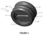
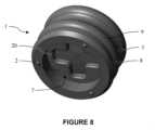
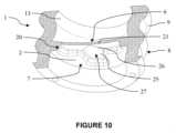
本発明によるバルブストッパー1の第2の一般的な実施形態は、図4~11および14~15に示され、図4~7および14は、バルブストッパーの第1の実施形態に向けられ、図8~11および15は、バルブストッパーの第2の実施形態に向けられている。A second general embodiment of the
第2の一般的な実施形態のバルブストッパーの一般的な構造は、前述の第1の一般的な実施形態の構造と同様であり、これ以上説明しない。図1~3および4~11に示されている第1の一般的な実施形態と第2の一般的な実施形態との間の共通の特徴には、同じ参照が与えられている。The general structure of the valve stopper of the second general embodiment is similar to that of the first general embodiment described above and will not be described further. Common features between the first and second general embodiments shown in Figures 1-3 and 4-11 are given the same references.
第1の一般的な実施形態に対する第2の一般的な実施形態の利点は、バルブストッパーの製造プロセス中に膜がその構造的完全性を維持することであり、これにより、特に真空を含むステップが実行されるときに、前記プロセスを実行しやすくする。The advantage of the second general embodiment over the first general embodiment is that the membrane maintains its structural integrity during the manufacturing process of the valve stopper, making said process easier to carry out, especially when steps involving a vacuum are performed.
第2の一般的な実施形態によれば、ノッチ20は、膜2の厚さの一部にのみ延びる。膜の厚さのうち、ノッチによって横断されない部分21は、引き裂き部分と呼ばれ、近位面6から遠位面7まで膜2を通る流体経路30を形成するように、組成物によって及ぼされる決定された圧力の下でノッチに沿って引き裂くように構成されている。According to a second general embodiment, the
そうするために、ノッチ20は、膜2に局所的な弱化ゾーンを形成し、これは、注入される組成物によってその近位面の前記1つに、決定された圧力が加えられると、膜を引き裂く。引き裂かれると、引き裂き部分21は、このように形成された流体経路に沿った組成物の流れのガイドとしても機能する。To do so, the
引き裂き部分21は、組成物によって膜2の近位面6に加えられる圧力に応じて、キャビティ4を開閉するように構成された弁を形成する。The tear-away
ノッチ20は、好ましくは膜の遠位面7から膜2の一部を通って延びる。あるいは、ノッチは、膜の近位面6から延びることができる。The
好ましくは、バルブストッパーは、1mLから3mLの間に含まれる注入容量を有する注入装置で使用され、膜2の厚さは、0.4mmから0.8mmの間に含まれ、好ましくは、膜2の厚さは、0.5mm以上であり、より好ましくは0.6mm以上である。Preferably, the valve stopper is used in an injection device having an injection volume comprised between 1 mL and 3 mL, and the thickness of the
ノッチ20の深さは、好ましくは、膜の厚さの約25%から50%の間、より好ましくは、膜の厚さの25%から35%の間で構成される。約0.5mmの厚さを有する膜の場合、ノッチ20の深さは、好ましくは0.1mm以上、より好ましくは0.2mm以上である。これは、前記膜を引き裂くのに必要な組成物によって及ぼされる圧力を下げることによって、膜の引き裂きを容易にする。The depth of the
第1の一般的な実施形態と同様に、第2の一般的な実施形態による膜2は、前記組成物が注入方向を意味する遠位方向に流れる場合にのみ、前記ノッチ20を介して前記膜を通過することができるように構成された一方向膜である。言い換えれば、引き裂き部分21は、組成物が膜の近位面6に接触するバルブストッパーの一方の側から、組成物が膜の遠位面7に接触するバルブストッパーの他方の側まで、組成物が膜を通過することを可能にするためにのみ開くように構成されている。それにより、膜の引き裂き部分21は、逆止弁として機能するように構成される。As with the first general embodiment, the
引き裂き部分21は、膜の近位面6に加えられる圧力P2が弁開放力Fopよりも小さい限り閉じたままであり、前記圧力P2がFop以上であるときに引き裂くことによって開くように構成され、 それにより、膜を通る流体経路が形成され、バルブストッパーに対して最初に近位に位置する組成物の注入を可能にする。The tearing
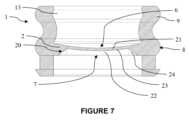
図4~7に示される第2の一般的な実施形態の第1の実施形態によれば、ノッチは楕円形の形態を有する。楕円形の形状は、共通の線23で結合する2つの対向する傾斜面22を含む。2つの対向する傾斜面22は、2つの円錐形の端部24によって横方向に結合されている。共通の線は、膜の引き裂き部分21に接触し、引き裂きの開始点を構成する。According to a first embodiment of the second general embodiment shown in Figures 4-7, the notch has an elliptical form. The elliptical shape includes two opposing
したがって、組成物によって膜に加えられる圧力がバルブ開放力Fopよりも大きい場合、共通の線23は引き裂かれ、膜2の引き裂き部分21の引き裂きを誘発する。これにより、膜を通る流体経路が作成される。Thus, when the pressure exerted by the composition on the membrane is greater than the valve opening force Fop, the
2つの傾斜面22の傾斜方向は、ノッチがそこから延びる膜の面に依存する。ノッチ20が膜の遠位面7から延びる場合、傾斜面22は、組成物の注入方向とは反対の近位方向に向けられる。逆に、ノッチ20が膜の近位面6から延びる場合、傾斜面22は、組成物の注入方向である遠位方向に向けられる。The direction of inclination of the two
楕円形のノッチには、さまざまな構造上のバリエーションを加えることができる。例えば、2つの円錐形の端部24は、互いに平行な2つの真っ直ぐな壁によって置き換えることができる。さらに、傾斜面と膜の近位面または遠位面との交点は、楕円形の縦方向の側面から、図4および5に示すように互いにわずかに曲がっていてもよいし、互いに平行な直線であってもよい。The elliptical notch can have many structural variations. For example, the two conical ends 24 can be replaced by two straight walls parallel to each other. Furthermore, the intersections of the inclined surfaces with the proximal or distal surfaces of the membrane can be slightly curved from the longitudinal sides of the ellipse to each other, as shown in Figures 4 and 5, or can be straight lines parallel to each other.
図8~11に示される第2の一般的な実施形態の第2の実施形態によれば、ノッチ20は十字の形態である。十字は、十字の中心で交差する2つの垂直なセグメント25を含む。膜は、好ましくは、十字の中心でのみ裂ける。センターは、図8と図9では、センター十字26と呼ばれる細い線で描かれた別の十字で表現されているが、これは随意である。センター十字26は、膜の引き裂き部分21に接触し、引き裂きの開始点を構成し得る。もちろん、十字20は一気に完全に裂ける可能性があり、センター十字26(存在する場合)および2つの垂直なセグメント25は実質的に同時に裂ける。According to a second embodiment of the second general embodiment shown in Figs. 8-11, the
したがって、組成物によって膜に加えられる圧力がバルブ開放力Fopよりも大きい場合、十字20は引き裂かれ、膜の引き裂き部分21の引き裂きを誘発する。これにより、膜を通る流体経路が作成される。好ましくは、センター十字26のみが裂け、センター十字を区切る十字の突出部分27は裂けないが、センター十字の引き裂きに追従するように変形し、こうして形成された流体経路に沿って組成物の流れを導くことができる。Thus, when the pressure exerted by the composition on the membrane is greater than the valve opening force Fop, the cross 20 tears, inducing tearing of the tearing
その長さ、幅、および深さなどのノッチ20の寸法は、第2の組成物を注入するために必要な注入力を調整するように適合させることができる。第2の一般的な実施形態の第1の実施形態、長方形の長さおよび幅に関して、傾斜面の傾斜角は、それに応じて適合させることができる。第2の一般的な実施形態の第2の実施形態に関して、十字の2つのセグメントの長さおよび幅もそれに応じて調整することができる。The dimensions of the
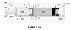
本発明のバルブストッパー1は、少なくとも1つの組成物を注入するために、好ましくは少なくとも2つの組成物を順次注入するために、注入装置100のバレル101の内側に配置されるように構成される。そのような注入装置の実施形態が図3Aに示されている。The
図3Aを参照すると、注入装置100は、近位端103から遠位端104まで延びるバレル101を含む注射器である。遠位端は、組成物の通過のためのチャネル106を囲む先端105を備えている。With reference to FIG. 3A, the
注入装置100は、組成物を注入するためにバレル内で並進的に移動可能であるように適合されたプランジャーストッパー107を備える。プランジャーストッパーは、有利には、前記プランジャーロッドがプランジャーストッパーを遠位方向に押して注入を行うときに前記ヘッドを収容するために、プランジャーロッドのヘッドの形状に対応する形状を有する中空容積110を備える。The
バルブストッパー1は、バレルの遠位端104とプランジャーストッパー107との間に配置され、バレル101内で並進運動可能である。バルブストッパー1は、バルブストッパー1とバレルの遠位端104との間の第1のチャンバー108と、バルブストッパー1とプランジャーストッパー107との間の第2のチャンバー109とを含む、バレルの2つのチャンバーを分離する。The
第1のチャンバー108は、最初に注入されることを意図された第1の組成物を含み、第2のチャンバー109は、第1の組成物が注入された後に注入されることを意図された第2の組成物を含む。The
第1および第2の組成物は、同じであっても異なっていてもよい。そのような組成物は、医薬であり得、粘弾性であり得る。The first and second compositions may be the same or different. Such compositions may be pharmaceutical and may be viscoelastic.
注入装置100は、2つ以上のバルブストッパー1を含み得、そして2つ以上の組成物を注入するために使用され得ることに留意されたい。例えば、注入装置は、バレルの遠位端と前記第1バルブストッパーとの間に位置する第1チャンバーと、前記第1バルブストッパーと第2バルブストッパーとの間に位置する第2チャンバーとを分離する第1バルブストッパーと、前記第2チャンバーを分離する第2バルブストッパーと、前記第2バルブストッパーとプランジャーストッパーとの間に位置する第3チャンバーとを含む2つのバルブストッパーを含み得る。第1、第2、および第3の各チャンバーには、組成物が含まれている。It should be noted that the
注入前に、スプリット10は閉じられ、これは、バルブストッパー1が注入装置のバレル101に挿入されるとき、スプリット10は、バルブストッパーの半径方向の圧縮下で閉じられたままであり、前記バルブストッパー自体がバレルの半径方向の圧縮にさらされることを意味する。クローズドスプリット10は、第1の組成物が第2のチャンバー109に入るのを防ぎ、第2の組成物が第1のチャンバー108に入るのを防ぐことによって、第1および第2の組成物の混合を防ぐ。Prior to injection, the
バルブストッパーの2つ以上のリブ9は、バレルの内面102に密封係合する。したがって、第1および第2の組成物は、バルブストッパー1とバレル101との間の通路を介してチャンバーから別のチャンバーに通過することができない。The two or
次に、図3Aから3Dを参照して、バルブストッパーおよび前記バルブストッパーを含む注入装置の機能を、本明細書の以下で説明する。Next, with reference to Figures 3A to 3D, the function of the valve stopper and the injection device including said valve stopper will be described hereinafter.
以下のステップでは、ノッチの第1の一般的な実施形態および第2の一般的な実施形態の両方について並行して説明される。In the following steps, both the first and second general embodiments of the notch are described in parallel.
図3Aは、第1の組成物の注入前の注入装置100の構成に対応する。Figure 3A corresponds to the configuration of the
この構成では、バルブストッパー1は、流体経路が閉じられている静止位置にある。第1の一般的な実施形態に関して、静止位置では、スプリット10は、バルブストッパーの半径方向の圧縮下で閉じた状態に維持され、プランジャーストッパー107は近位位置にある。第2の一般的な実施形態に関して、静止位置では、膜の引き裂き部分21は構造的に無傷であり、したがって、キャビティ4は閉じられている。In this configuration, the
第1のチャンバー108の圧力P1および第2のチャンバー109の圧力P2は実質的に等しく、その結果、差圧ΔP=P2-P1は実質的に零であり、したがってスプリットのバルブ開放力Fopよりはるかに低い 。したがって、ノッチは閉じたままである。The pressure P1 in the
ユーザーは最初の組成物の注入を実行する。注入装置100の構成は、図3Aと図3Bの構成の間にある。プランジャーストッパー107に加えられた力は、第2のチャンバー109に伝達され、次にバルブストッパー1に伝達され、その結果、第2の組成物によってバルブストッパーの膜2の近位面に加えられる力F2が生じる。The user performs an injection of the first composition. The configuration of the
遠位方向へのバルブストッパー1の変位は、第1の組成物を遠位方向に押し、前記第1の組成物は、先端のチャネル106によって注射器から排出される。この構成では、バルブストッパー1はシール位置にある。Displacement of the
チャネル106の直径がバレル101の直径よりもはるかに小さいので、バルブストッパー1の変位は、第1のチャンバー108内に圧力を蓄積する。圧力P1のこの増加は、注入のためのチャネルを通して第1の組成物を強制するだけでなく、バルブストッパーの変位とは反対に、バルブストッパーの膜の遠位面7にも適用される。結果として、バルブストッパー1は、第1の組成物および第2の組成物によってそれぞれバルブストッパーの膜の近位面6および遠位面7に加えられる実質的に等しく反対の圧力P1およびP2にさらされる。Because the diameter of the
結果として、差圧ΔPは実質的に零であり、したがって、ノッチのバルブ開放力Fopよりもはるかに低い 。バルブストッパー1の変位中、差圧ΔPは実質的に零ではないかもしれないが、ノッチのバルブ開放力Fopよりも低いままである 。したがって、第1の一般的な実施形態のスプリット10は閉じたままである。第2の一般的な実施形態の引き裂き部分21は無傷のままである。As a result, the pressure difference ΔP is substantially zero and therefore much lower than the valve opening force Fop of the notch. During the displacement of the
図3Bに示されるように、注入は、バルブストッパー1がバレルの遠位端104に隣接するまで続く。第1の組成物の一部は、依然として第1のチャンバー108に残っている。As shown in FIG. 3B, injection continues until the
バルブストッパー1はそれ以上遠位に移動することができないので、第2のチャンバー109内の圧力P2は増加し、力差ΔPは弁開放力Fopよりも大きいものになる。Because the
結果として、第1の一般的な実施形態に関して、スプリットは開き、それにより、図3Cに示されるように、第2の組成物が、注入のためのチャネルまで前記スプリットを通過することを可能にする。この構成では、バルブストッパーは注入位置にある。As a result, for the first general embodiment, the split opens, thereby allowing the second composition to pass through said split to the channel for injection, as shown in FIG. 3C. In this configuration, the valve stopper is in the injection position.
この状況は、図3Eにも詳細に表されており、第2の組成物によって膜2に加えられる力は矢印F2で表され、弁を開く力は小さい矢印F2aで示されている。This situation is also shown in detail in FIG. 3E, where the force exerted by the second composition on the
第2の一般的な実施形態に関して、引き裂き部分21は引き裂かれ、それにより膜を通る流体経路30が形成され、第2の組成物が流体経路に沿って、ノッチおよび引き裂かれた引き裂き部分21を通って、注入用のチャネルに通過することができる。For the second general embodiment, the
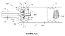
この状況はまた、第2の一般的な実施形態の第1および第2の実施形態について図12Aおよび13Aにさらに詳細に表され、ここで、第2の組成物によって膜2に及ぼされる力は矢印F2によって表され、流体経路を開放するための力は、小さい矢印F2aで示されている。流体経路30は点線で示されている。This situation is also depicted in more detail in Figures 12A and 13A for the first and second embodiments of the second general embodiment, where the force exerted by the second composition on the
図14および15は、第2の一般的な実施形態の第1および第2の実施形態の流体経路30の開口部を、バルブストッパーの全体斜視図とともに示している。Figures 14 and 15 show the openings of the
この構成では、バルブストッパーは注射位置にある。In this configuration, the valve stopper is in the injection position.
前に説明したように、この時点で、第1の組成物の一部が第1のチャンバー108に残っている。したがって、第2の組成物の注入の開始時に、第1の組成物の一部および少量の第2の組成物は、両方の組成物が同じ流体経路を通して注入されるので、混合され得る。As previously explained, at this point, a portion of the first composition remains in the
第2の組成物の注入の終わりに、プランジャーストッパー107は、バルブストッパー1に隣接する。第2の組成物の一部は、デッドボリュームに対応する第1のチャンバー108に残る。At the end of the injection of the second composition, the
バルブストッパー1は、プランジャーストッパー107によって加えられた圧力の下で崩壊し、崩壊は、内側の凹部のおかげで開始される。したがって、図3Dに示すように、バルブストッパーは折りたたまれた位置にある。バルブストッパーの崩壊により、キャビティ4の容積が減少し、デッドボリュームが注入される。The
バルブストッパーが近位キャビティを含む場合(図示せず)、プランジャーストッパーは、有利には、前記近位キャビティに適合する遠位ピンを含み得る。このようにして、前記ピンがバルブストッパーの近位キャビティに係合することにより、第2の組成物を近位キャビティからスプリットを通して排出することが可能になる。If the valve stopper includes a proximal cavity (not shown), the plunger stopper may advantageously include a distal pin that fits into said proximal cavity. In this way, engagement of said pin with the proximal cavity of the valve stopper allows the second composition to be expelled from the proximal cavity through the split.
一実施形態によれば、静止位置にあるバルブストッパーは、注射器の遠位端に接触する。この構成では、第1のチャンバーの容積が最小化される。第2のチャンバーは、注入される組成物を含む。この構成は、1つの組成物、特に薬物のみを注入する場合に特に有用であり、前記薬物(たとえばエピネフリン)は汚染物質に非常に敏感であり、したがって(たとえば針の)接着剤/金属または空気からの追加の保護が必要である。According to one embodiment, the valve stopper in the rest position contacts the distal end of the syringe. In this configuration, the volume of the first chamber is minimized. The second chamber contains the composition to be injected. This configuration is particularly useful when injecting only one composition, especially a drug, which (e.g. epinephrine) is very sensitive to contaminants and therefore requires additional protection from glue/metal (e.g. of the needle) or air.
好ましい実施形態によれば、吸引効果を生成し、空である第1のチャンバーを組成物で満たすことを可能にするために、バルブストッパーが近位方向に動かされる。この組成物は通常、血液または別の薬物であり、この場合、この操作は「静脈検査」または「再構成」と呼ばれる。According to a preferred embodiment, the valve stopper is moved proximally to create a suction effect and allow the empty first chamber to fill with the composition. This composition is usually blood or another drug, in which case the operation is called "intravenous check" or "reconstitution."
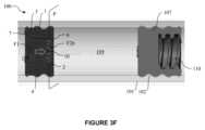
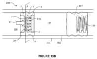
静脈試験または再構成中、チェックバルブ機能(図3F、12B、および13B)のおかげでノッチは閉じたままであり、それによって吸引された組成物が最初の組成物と混合するのを防ぐ。吸引力は矢印F1で表され、流体経路を閉じた状態に維持する、第2の組成物によって膜に加えられる力は、小さい矢印F2bで表される。During venous testing or reconstitution, the notch remains closed thanks to the check valve function (Figs. 3F, 12B, and 13B), thereby preventing the aspirated composition from mixing with the first composition. The aspiration force is represented by arrow F1, and the force exerted on the membrane by the second composition, which keeps the fluid path closed, is represented by the small arrow F2b.
静脈試験または再構成は、第1の組成物の注入の前に実施することができる。この場合、別のバルブストッパーがバレルの遠位端と第1の組成物との間に設けられる。A vein test or reconstitution can be performed prior to injection of the first composition. In this case, a separate valve stopper is provided between the distal end of the barrel and the first composition.
あるいは、静脈試験または再構成は、第1の組成物の注入中に実施され得る。この場合、注入は一時的に停止され、静脈検査が行われる。その後、第1の組成物の注入が再開される。Alternatively, the vein test or reconstitution may be performed during the infusion of the first composition. In this case, the infusion is temporarily stopped and a vein test is performed. The infusion of the first composition is then resumed.
本発明はまた、少なくとも1つの組成物を注射するための医療用注入装置100に関する。医療用注入装置は、
- 近位端103から遠位端104まで延びるバレル101と、
- バレル101内で並進移動可能に適合されたプランジャーストッパー107と、
- 前述のバルブストッパー1であって、バレルの遠位端104とプランジャーストッパー107との間に配置され、バレル101内で並進移動可能に適合されており、バルブストッパー1の側壁3がバレルの内面102に密封係合する、バルブストッパーと、を備える。 The present invention also relates to a
a
a
a
注入力の測定
第1の一般的な実施形態による本発明によるバルブストッパー、および当技術分野で知られているストッパーの注入力を決定するために、試験が実施されてきた。Measurement of Injection Force Tests have been carried out to determine the injection force of the valve stopper according to the present invention according to a first general embodiment, and of stoppers known in the art.
例えば、特許文献4において当技術分野で知られているストッパーは、ストッパーの円周に沿って半径方向外向きに延びるリブを備える。前記ストッパーが使用される場合、組成物は、リブとバレルの内面との間の通路を通過することが意図されている。従来の設計には、いかなるスプリットも含まれていない。当技術分野で知られている前記ストッパーの総体積は、約4mm3である。比較として、本発明のバルブストッパーの総体積は約162mm3である。 For example, stoppers known in the art in US Pat. No. 5,999,333 include ribs extending radially outward along the circumference of the stopper. When the stopper is used, the composition is intended to pass through a passage between the rib and the inner surface of the barrel. The conventional design does not include any splits. The total volume of the stoppers known in the art is about 4mm3 . In comparison, the total volume of the valve stopper of the present invention is about 162mm3 .
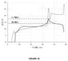
バルブストッパーが密封位置にあるシリンジが使用されており、これは、前記バルブストッパーがシリンジのバレルの遠位端に隣接していないことを意味する(図3Aに対応する)。バレルの遠位端とバルブストッパー/既知の従来技術のストッパーとの間、およびバルブストッパー/既知の従来技術のストッパーとプランジャーストッパーとの間の両方のチャンバーは、注射器から排出される組成物を含む。注射器はテストベンチに取り付けられている。プランジャーストッパーは機械的に遠位方向に動かされ、プランジャーストッパーに加えられた力はベンチの変位の関数として記録された。この力は、バルブストッパー/既知の従来技術のストッパーの注入力に対応する。前記力は、バルブストッパー/既知の従来技術のストッパーのバルブ開放力Fopを含み、これは、曲線注入力(図3Bの構成に対応する)の局所的なピークに対応し、組成物が注入される際の滑動力にも対応している。バルブストッパーの前記注入力(N)は、ベンチ変位(mm)の関数として図16に表されている。バルブ開放力と最大滑動力の両方が表されている。本発明によるバルブストッパーの注入力は実線で表され、既知の従来技術のストッパーの注入力は点線で表されている。A syringe is used with the valve stopper in the sealed position, meaning that the valve stopper is not adjacent to the distal end of the barrel of the syringe (corresponding to FIG. 3A). Both chambers, between the distal end of the barrel and the valve stopper/known prior art stopper, and between the valve stopper/known prior art stopper and the plunger stopper, contain the composition that is expelled from the syringe. The syringe is mounted on a test bench. The plunger stopper is mechanically moved distally and the force applied to the plunger stopper is recorded as a function of the bench displacement. This force corresponds to the injection force of the valve stopper/known prior art stopper. The force includes the valve opening force Fop of the valve stopper/known prior art stopper, which corresponds to the local peak of the curve injection force (corresponding to the configuration of FIG. 3B) and also corresponds to the sliding force when the composition is injected. The injection force of the valve stopper (N) is represented in FIG. 16 as a function of bench displacement (mm). Both the valve opening force and the maximum sliding force are represented. The injection force of the valve stopper according to the present invention is shown by a solid line, while the injection force of the known prior art stopper is shown by a dotted line.
ベンチ変位が12mmの場合、注入力は約12Nまで増加する。これは、バルブストッパーの動作設定に対応しており、前記バルブストッパーに一定の力を加える必要がある。When the bench displacement is 12 mm, the injection force increases to approximately 12 N. This corresponds to the valve stopper operating setting, which requires a constant force to be applied to the valve stopper.
その後、滑動力は、ベンチ変位が30mmになるまで実質的に一定に保たれる。これは、バレルの遠位端とバルブストッパーとの間に最初に含まれる第1の組成物を注入するための、遠位方向のバルブストッパーの変位に対応する。この力は、従来の設計で観察された力と同等である。The sliding force is then held substantially constant until the bench displacement reaches 30 mm, which corresponds to the displacement of the valve stopper in the distal direction to inject the first composition initially contained between the distal end of the barrel and the valve stopper. This force is comparable to that observed with the conventional design.
その後、ベンチ変位が35mmに達すると、注入力が急激に増加し、バルブ開放力Fopに対応する17.5Nの曲線の最大値に達する。Then, when the bench displacement reaches 35 mm, the injection force increases sharply and reaches a maximum value on the curve of 17.5 N, which corresponds to the valve opening force Fop.
次に、注入力は、第2の組成物を注入するための最大滑動力に対応する約14Nの平均値へと減少する。The injection force then decreases to an average value of approximately 14 N, which corresponds to the maximum sliding force for injecting the second composition.
その後、バルブストッパーが崩壊し、2回目の注入が終了し、注入力が大幅に低下する。
バルブ開放力と滑動力の平均値の決定
第1の一般的な実施形態による本発明のいくつかのバルブストッパーおよび既知の先行技術のいくつかのストッパーについて、前述の試験が数回実施された。各試験で測定されたバルブ開放力Fopおよび前記異なるストッパーの最大滑動力の平均値は、それぞれ図17のグラフおよび図18のグラフに示されている。 The valve stopper then collapses, terminating the second injection and causing a significant reduction in injection force.
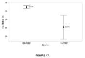
Determination of the average values of the valve opening force and the sliding force The aforementioned tests were carried out several times on several valve stoppers of the present invention according to the first general embodiment and on several stoppers of the known prior art. The average values of the valve opening force Fop and the maximum sliding force of the different stoppers measured in each test are shown in the graphs of Fig. 17 and Fig. 18, respectively.
図17については、従来の設計に関して、バルブ開放力の平均値は27.5Nである。Referring to Figure 17, for the conventional design, the average valve opening force is 27.5 N.
標準偏差も、2つのセグメントで区切られた垂直線でグラフに表される。標準偏差が小さいということは、測定値が異なると、平均値である27.5Nに近いバルブ開放力の値が得られることを意味している。The standard deviation is also represented on the graph by a vertical line separated by two segments. A small standard deviation means that different measurements yield values of valve opening force close to the average value of 27.5 N.
本発明のバルブストッパー(「バルブ設計」)に関しては、バルブ開放力の平均値は15.5Nであり、従来の設計よりもはるかに低い。異なる厚さの膜を提示するバルブストッパーを使用してテストが実行されたため、標準偏差が高くなり、これは、スプリットの厚さに直接影響し、それによってバルブ開放力にも影響する。For the valve stopper of the present invention ("valve design"), the average valve opening force is 15.5 N, which is much lower than the conventional design. The standard deviation is higher because tests were performed with valve stoppers presenting membranes of different thicknesses, which directly affects the split thickness and thereby the valve opening force.
したがって、本発明のバルブストッパーは、従来の設計よりもはるかに低いバルブ開放力をもたらす。バルブ開放力は、使用者による組成物の注入を非常に容易にし、ひずみによる損傷を防ぐために十分に低く、そして、医薬組成物がその注入前に誤ってそのチャンバーを離れることを防ぐことによってバレルの堅固な密封を確実にするために十分に高くなっている。The valve stopper of the present invention thus provides a much lower valve opening force than conventional designs. The valve opening force is low enough to make it very easy for the user to inject the composition, to prevent damage from strain, and high enough to ensure a tight seal of the barrel by preventing the pharmaceutical composition from accidentally leaving the chamber prior to its injection.
図18については、従来の設計の場合、最大滑動力の平均値は22.1Nである。標準偏差は小さく、測定値の違いによって平均値である22.1Nに近い滑動力の値が得られていることになる。In Figure 18, for the conventional design, the average maximum sliding force is 22.1 N. The standard deviation is small, which means that differences in the measurements result in sliding force values close to the average value of 22.1 N.
本発明のバルブストッパーに関しては、最大滑動力の平均値は12.7Nであり、従来の設計よりもはるかに低い。膜の厚さが異なるバルブストッパーを使用してテストが実行されたため、標準偏差は平均であり、これは、バルブストッパーの重量に影響を与え、それによって滑動力にも影響を与える。For the valve stopper of the present invention, the average value of the maximum sliding force is 12.7 N, which is much lower than the conventional design. The standard deviation is the average because tests were performed using valve stoppers with different membrane thicknesses, which affects the weight of the valve stopper and therefore the sliding force.
したがって、本発明のバルブストッパーは、従来の設計よりもはるかに低いバルブ開放力をもたらす。これは、1つまたは複数のリブが組成物の通路を形成するのではなく、バレルの内面と恒常的に接触しているためで、バルブストッパーがシリンジの軸に対してオフセットするのを防ぎ、注入をよりスムーズに行うことができる。バルブ開放力は、使用者による組成物の注入を非常に容易にし、ひずみによる損傷を防ぐために十分に低く、そして、医薬組成物がその注入前に誤ってそのチャンバーを離れることを防ぐことによってバレルの堅固な密封を確実にするために十分に高くなっている。The valve stopper of the present invention thus provides a much lower valve opening force than conventional designs because the rib or ribs are in constant contact with the inner surface of the barrel rather than forming a passageway for the composition, preventing the valve stopper from offsetting relative to the axis of the syringe and allowing for a smoother injection. The valve opening force is low enough to make it very easy for the user to inject the composition, to prevent damage from distortion, and high enough to ensure a tight seal of the barrel by preventing the pharmaceutical composition from accidentally leaving its chamber prior to its injection.
Claims (19)
Translated fromJapanese- 近位面(6)および遠位面(7)を含み、前記膜は、前記バレルの第1の遠位チャンバー(108)と前記バレルの第2の近位チャンバー(109)とを分離するように構成されている、膜(2)と、
- 少なくとも遠位キャビティ(4)を画定するために、前記膜(2)から遠位に、または遠位と近位の両方に延び、前記バレルの内面(102)に密封係合するように構成された円周方向の密封面(8)を備える、側壁(3)と、
を備え、
前記膜(2)の前記近位面(6)が凹状形状を呈し、前記膜(2)は、前記近位面(6)と前記遠位面(7)との間の一部を通って延びるノッチ(10,20)を有し、
前記側壁(3)は、組成物によって前記膜(2)の前記近位面(6)に対して遠位方向に作用する機械的圧力の下で前記バルブストッパー(1)の崩壊を誘発するように構成された内部凹部(13)を有し、
前記ノッチ(10,20)は、前記第2のチャンバー(109)から前記第1のチャンバー(108)に流体のみを移動させるために、組成物によって前記膜(2)の前記近位面(6)に及ぼされる前記機械的圧力に応じて崩壊することにより、前記近位面(6)から前記遠位面(7)まで前記膜(2)を通る流体経路(30)を選択的に形成するように構成されていることを特徴とする、バルブストッパー(1)。 A valve stopper (1) configured to be placed inside a barrel (101) of an injection device (100) for injecting at least one composition through a distal end (104) of the barrel, said valve stopper (1) comprising:
a membrane (2)comprising a proximal face (6) and a distal face (7), said membrane being configured to separate a first distal chamber (108) of said barrel and a second proximal chamber (109) of said barrel;
a side wall (3)extending distally, or both distally and proximally, from said membrane (2) to define at least a distal cavity (4) and comprising a circumferential sealing surface (8) configured for sealing engagement with an inner surface (102) of said barrel;
Equipped with
the proximal surface (6) of the membrane (2) is concave in shape, the membrane (2)havinga notch (10, 20) extendingpartially through between the proximal surface (6) and the distal surface (7);
the side wall (3) having an internal recess (13) configured to induce collapse of the valve stopper (1) under mechanical pressure exerted by a composition in a distal direction against the proximal face (6) of the membrane (2);
the notches (10, 20) are configured to collapse in response to the mechanical pressure exerted by a composition on the proximal surface (6) of the membrane (2)to selectively form afluid path (30) through the membrane (2) from the proximal surface (6) to the distal surface (7) to move only fluid from the second chamber (109) to the first chamber (108).
- 近位端(103)から遠位端(104)まで延びるバレル(101)と、
- 前記バレル(101)の内部で並進移動可能に適合されたプランジャーストッパー(107)と、
- 請求項1から13のいずれか1項に記載のバルブストッパー(1)であって、前記バレルの前記遠位端(104)と前記プランジャーストッパー(107)との間に配置され、前記バレル(101)の内部で並進移動可能に適合されており、前記バルブストッパー(1)の前記側壁(3)が前記バレルの内面(102)に密封係合しているバルブストッパー(1)と、
を備える、医療用注入装置(100)。 A medical injection device (100) for injecting at least one composition, comprising:
a barrel (101) extending from a proximal end (103) to a distal end (104);
a plunger stopper (107) adapted for translational movement inside said barrel (101);
a valve stopper (1) according to any one of claims 1 to13 , arranged between the distal end (104) of the barrel and the plunger stopper (107), adapted for translational movement inside the barrel (101), the side wall (3) of the valve stopper (1) being in sealing engagement with an inner surface (102) of the barrel;
A medical injection device (100) comprising:
- 前記流体経路(30)が閉じている静止位置と、
- 前記バルブストッパー(1)が、前記流体経路(30)が閉じている静止位置よりも遠位にあり、前記近位面(6)が、前記ノッチ(10)のバルブ開放力Fopよりも小さい前記機械的圧力を受けている封止位置と、
- 前記バルブストッパー(1)が前記バレル(101)の前記遠位端(104)に接しており、前記近位面(6)に、前記ノッチ(10)のバルブ開放力Fopよりも大きい前記機械的圧力がかかることによって、前記流体経路(30)が開放されている注入位置と、
を呈する、請求項14または請求項15に記載の医療用注入装置(100)。 The valve stopper (1) is in the following successive positions:
a rest position in which said fluid path (30) is closed;
a sealed position in which the valve stopper (1) is distal to its rest position in which the fluid path (30) is closedand in which the proximal face (6) is subjected tothe mechanical pressure which is less than the valve opening force Fop of the notch (10);
an injection position in which the valve stopper (1) is in contact with the distal end (104) of the barrel (101)and the fluid path (30) is opened by applyingthe mechanical pressure on the proximal face (6) that is greater than the valve opening force Fop of the notch (10);
16. The medical injection device (100) of claim14 or claim15 , exhibiting
Applications Claiming Priority (5)
| Application Number | Priority Date | Filing Date | Title |
|---|---|---|---|
| EP19305230 | 2019-02-27 | ||
| EP19305230.5 | 2019-02-27 | ||
| EP19305647.0 | 2019-05-22 | ||
| EP19305647 | 2019-05-22 | ||
| PCT/EP2020/054902WO2020173938A1 (en) | 2019-02-27 | 2020-02-25 | Valve stopper for a medical injection device and medical injection device for injecting at least one composition |
Publications (2)
| Publication Number | Publication Date |
|---|---|
| JP2022522172A JP2022522172A (en) | 2022-04-14 |
| JP7531505B2true JP7531505B2 (en) | 2024-08-09 |
Family
ID=69593716
Family Applications (1)
| Application Number | Title | Priority Date | Filing Date |
|---|---|---|---|
| JP2021549995AActiveJP7531505B2 (en) | 2019-02-27 | 2020-02-25 | Valve stopper for a medical injection device and medical injection device for injecting at least one composition - Patents.com |
Country Status (9)
| Country | Link |
|---|---|
| US (1) | US20220134003A1 (en) |
| EP (1) | EP3930795A1 (en) |
| JP (1) | JP7531505B2 (en) |
| KR (2) | KR102788920B1 (en) |
| CN (1) | CN113498351B (en) |
| BR (1) | BR112021016442A2 (en) |
| CA (1) | CA3129652A1 (en) |
| MX (2) | MX2021009713A (en) |
| WO (1) | WO2020173938A1 (en) |
Families Citing this family (11)
| Publication number | Priority date | Publication date | Assignee | Title |
|---|---|---|---|---|
| GB202104609D0 (en) | 2021-03-31 | 2021-05-12 | Sevenless Therapeutics Ltd | New Treatments for Pain |
| CA3213593A1 (en) | 2021-03-31 | 2022-10-06 | Sevenless Therapeutics Limited | Sos1 inhibitors and ras inhibitors for use in the treatment of pain |
| EP4598538A1 (en) | 2022-10-05 | 2025-08-13 | Sevenless Therapeutics Limited | New treatments for pain |
| US20240148973A1 (en)* | 2022-11-09 | 2024-05-09 | Becton, Dickinson And Company | Dual chamber syringe assembly with floating stopper |
| US20240173480A1 (en)* | 2022-11-30 | 2024-05-30 | Becton, Dickinson And Company | Syringe with concentric dual chambers |
| US20240173481A1 (en)* | 2022-11-30 | 2024-05-30 | Becton, Dickinson And Company | Syringe with tandem dual chambers |
| US20240252758A1 (en)* | 2023-01-31 | 2024-08-01 | Credence Medsystems, Inc. | Injection system and method |
| WO2024242865A1 (en)* | 2023-05-24 | 2024-11-28 | Becton, Dickinson And Company | Stoppering tool system for installing a valved stopper in a syringe barrel |
| EP4541387A1 (en) | 2023-10-16 | 2025-04-23 | Becton Dickinson France | Sequential-injection syringe |
| WO2025184096A1 (en)* | 2024-02-26 | 2025-09-04 | Becton, Dickinson And Company | Valve stopper for a multi-chamber medical injection device |
| WO2025184100A1 (en)* | 2024-02-26 | 2025-09-04 | Becton, Dickinson And Company | Valve stopper for a multi-chamber medical injection device |
Citations (3)
| Publication number | Priority date | Publication date | Assignee | Title |
|---|---|---|---|---|
| JP2000210384A (en) | 1999-01-26 | 2000-08-02 | Naigai Kasei Kk | Medical stopper |
| JP2007535987A (en) | 2004-05-03 | 2007-12-13 | インヒュースィヴ・テクノロジーズ・エルエルシー | Multi-chamber sequential dose dispensing syringe |
| WO2017170634A1 (en) | 2016-03-30 | 2017-10-05 | テルモ株式会社 | Seal member, syringe assembly, and prefilled syringe |
Family Cites Families (24)
| Publication number | Priority date | Publication date | Assignee | Title |
|---|---|---|---|---|
| US4929230A (en) | 1988-09-30 | 1990-05-29 | Pfleger Frederick W | Syringe construction |
| IS4223A (en)* | 1993-11-03 | 1995-05-04 | Astra Ab | Apparatus for mixing pharmaceutical composition with another substance |
| JPH09173450A (en)* | 1995-12-26 | 1997-07-08 | Nissho Corp | Prefilled syringe |
| FR2822710B1 (en) | 2001-03-27 | 2004-04-02 | Lab Contactologie Appl Lca | SYRINGE FOR VISCOLEASTIC SOLUTIONS |
| US6723074B1 (en)* | 2002-04-09 | 2004-04-20 | Thor R. Halseth | Sequential delivery syringe |
| US7601141B2 (en)* | 2002-11-26 | 2009-10-13 | Nexus Medical, Llc | Pressure actuated flow control valve |
| CN2621701Y (en)* | 2003-04-18 | 2004-06-30 | 刘文照 | Environmental protection syringe |
| US9933079B2 (en)* | 2004-01-29 | 2018-04-03 | Angiodynamics, Inc. | Stacked membrane for pressure actuated valve |
| US7101354B2 (en)* | 2004-05-03 | 2006-09-05 | Infusive Technologies, Llc | Mixing syringe with and without flush |
| JP4686202B2 (en) | 2005-02-02 | 2011-05-25 | 大成化工株式会社 | Syringe |
| WO2008045042A1 (en)* | 2006-10-10 | 2008-04-17 | Infusive Technologies, Llc | Multi-chamber, sequential dose dispensing syringe |
| WO2009094345A1 (en)* | 2008-01-23 | 2009-07-30 | Mallinckrodt Inc. | Plunger adapter coaxial syringe system |
| US20110087093A1 (en)* | 2009-10-09 | 2011-04-14 | Navilyst Medical, Inc. | Valve configurations for implantable medical devices |
| KR20110041826A (en)* | 2009-10-16 | 2011-04-22 | 조희민 | Syringes with check valves for heterogeneous liquid mixing |
| WO2011092536A1 (en)* | 2010-01-26 | 2011-08-04 | Becton Dickinson France | Drug cartrigde different inner surface conditions |
| US8172794B2 (en)* | 2010-03-15 | 2012-05-08 | Becton, Dickinson And Company | Medical device including an air evacuation system |
| US9289562B2 (en)* | 2011-04-18 | 2016-03-22 | THORNE CONSULTING and INTELETUAL PROPERTY, LLC | Pressure actuated valve for multi-chamber syringe applications |
| US9950114B2 (en)* | 2011-05-13 | 2018-04-24 | Thorne Consulting For International Property, Llc | Dual-chamber syringe and associated connecting systems |
| WO2014004695A1 (en)* | 2012-06-26 | 2014-01-03 | Glucago, Llc | Reconstitution device |
| AU2014318264B2 (en)* | 2013-09-16 | 2018-10-04 | Zoetis Services Llc | Assembly for sequentially delivering substances, and associated methods |
| WO2015071352A1 (en)* | 2013-11-14 | 2015-05-21 | Sfm Medical Devices Gmbh | Syringe for sequential injection of active ingredients |
| WO2017069818A1 (en)* | 2015-10-23 | 2017-04-27 | Thorne Consulting And Intellectual Property, Llc | Dual-chamber syringe and associated connecting systems |
| KR20180002647U (en)* | 2017-02-28 | 2018-09-05 | 라보라뜨와 메디동 소시에떼아노님 | Injection syringe for intra-articular administration |
| RU2742443C1 (en)* | 2017-10-23 | 2021-02-05 | Аптаргруп, Инк. | Valve |
- 2020
- 2020-02-25JPJP2021549995Apatent/JP7531505B2/enactiveActive
- 2020-02-25EPEP20705751.4Apatent/EP3930795A1/enactivePending
- 2020-02-25BRBR112021016442Apatent/BR112021016442A2/enunknown
- 2020-02-25USUS17/434,103patent/US20220134003A1/enactivePending
- 2020-02-25CNCN202080016838.3Apatent/CN113498351B/enactiveActive
- 2020-02-25CACA3129652Apatent/CA3129652A1/enactivePending
- 2020-02-25MXMX2021009713Apatent/MX2021009713A/enunknown
- 2020-02-25KRKR1020217028474Apatent/KR102788920B1/enactiveActive
- 2020-02-25WOPCT/EP2020/054902patent/WO2020173938A1/ennot_activeCeased
- 2020-02-25KRKR1020257009365Apatent/KR20250047406A/enactivePending
- 2021
- 2021-08-12MXMX2025004048Apatent/MX2025004048A/enunknown
Patent Citations (3)
| Publication number | Priority date | Publication date | Assignee | Title |
|---|---|---|---|---|
| JP2000210384A (en) | 1999-01-26 | 2000-08-02 | Naigai Kasei Kk | Medical stopper |
| JP2007535987A (en) | 2004-05-03 | 2007-12-13 | インヒュースィヴ・テクノロジーズ・エルエルシー | Multi-chamber sequential dose dispensing syringe |
| WO2017170634A1 (en) | 2016-03-30 | 2017-10-05 | テルモ株式会社 | Seal member, syringe assembly, and prefilled syringe |
Also Published As
| Publication number | Publication date |
|---|---|
| BR112021016442A2 (en) | 2021-11-09 |
| EP3930795A1 (en) | 2022-01-05 |
| KR20210131356A (en) | 2021-11-02 |
| CA3129652A1 (en) | 2020-09-03 |
| CN113498351B (en) | 2023-12-12 |
| CN113498351A (en) | 2021-10-12 |
| WO2020173938A1 (en) | 2020-09-03 |
| MX2025004048A (en) | 2025-05-02 |
| MX2021009713A (en) | 2021-09-08 |
| JP2022522172A (en) | 2022-04-14 |
| KR20250047406A (en) | 2025-04-03 |
| KR102788920B1 (en) | 2025-04-01 |
| US20220134003A1 (en) | 2022-05-05 |
Similar Documents
| Publication | Publication Date | Title |
|---|---|---|
| JP7531505B2 (en) | Valve stopper for a medical injection device and medical injection device for injecting at least one composition - Patents.com | |
| JP7053709B2 (en) | Vial transfer and injection equipment and methods | |
| US7018356B2 (en) | Method and apparatus for adjusting the contents of a needle-less injector | |
| US20040064105A1 (en) | Single-use syringe | |
| JPH0380029B2 (en) | ||
| MX2008009464A (en) | A BLISTER USED AS A SYRINGE AND A SYRINGE UNIT THAT UNDERSTANDS THE BLISTER. | |
| JP7702962B2 (en) | Stopper for medical infusion device | |
| WO2025217032A1 (en) | Valve stopper for a multi-chamber medical injection device | |
| WO2025184096A1 (en) | Valve stopper for a multi-chamber medical injection device | |
| WO2025184100A1 (en) | Valve stopper for a multi-chamber medical injection device | |
| CN120615020A (en) | Injection systems and methods |
Legal Events
| Date | Code | Title | Description |
|---|---|---|---|
| A621 | Written request for application examination | Free format text:JAPANESE INTERMEDIATE CODE: A621 Effective date:20221207 | |
| A977 | Report on retrieval | Free format text:JAPANESE INTERMEDIATE CODE: A971007 Effective date:20231020 | |
| A131 | Notification of reasons for refusal | Free format text:JAPANESE INTERMEDIATE CODE: A131 Effective date:20231121 | |
| A601 | Written request for extension of time | Free format text:JAPANESE INTERMEDIATE CODE: A601 Effective date:20240221 | |
| A521 | Request for written amendment filed | Free format text:JAPANESE INTERMEDIATE CODE: A523 Effective date:20240422 | |
| TRDD | Decision of grant or rejection written | ||
| A01 | Written decision to grant a patent or to grant a registration (utility model) | Free format text:JAPANESE INTERMEDIATE CODE: A01 Effective date:20240702 | |
| A61 | First payment of annual fees (during grant procedure) | Free format text:JAPANESE INTERMEDIATE CODE: A61 Effective date:20240730 | |
| R150 | Certificate of patent or registration of utility model | Ref document number:7531505 Country of ref document:JP Free format text:JAPANESE INTERMEDIATE CODE: R150 |