JP7531236B2 - Left atrial appendage closure device - Google Patents
Left atrial appendage closure deviceDownload PDFInfo
- Publication number
- JP7531236B2 JP7531236B2JP2022519406AJP2022519406AJP7531236B2JP 7531236 B2JP7531236 B2JP 7531236B2JP 2022519406 AJP2022519406 AJP 2022519406AJP 2022519406 AJP2022519406 AJP 2022519406AJP 7531236 B2JP7531236 B2JP 7531236B2
- Authority
- JP
- Japan
- Prior art keywords
- closure device
- balloon
- proximal
- end portion
- inventive concept
- Prior art date
- Legal status (The legal status is an assumption and is not a legal conclusion. Google has not performed a legal analysis and makes no representation as to the accuracy of the status listed.)
- Active
Links
Images


Classifications
- A—HUMAN NECESSITIES
- A61—MEDICAL OR VETERINARY SCIENCE; HYGIENE
- A61B—DIAGNOSIS; SURGERY; IDENTIFICATION
- A61B17/00—Surgical instruments, devices or methods
- A61B17/12—Surgical instruments, devices or methods for ligaturing or otherwise compressing tubular parts of the body, e.g. blood vessels or umbilical cord
- A61B17/12022—Occluding by internal devices, e.g. balloons or releasable wires
- A61B17/12131—Occluding by internal devices, e.g. balloons or releasable wires characterised by the type of occluding device
- A61B17/12168—Occluding by internal devices, e.g. balloons or releasable wires characterised by the type of occluding device having a mesh structure
- A61B17/12172—Occluding by internal devices, e.g. balloons or releasable wires characterised by the type of occluding device having a mesh structure having a pre-set deployed three-dimensional shape
- A—HUMAN NECESSITIES
- A61—MEDICAL OR VETERINARY SCIENCE; HYGIENE
- A61B—DIAGNOSIS; SURGERY; IDENTIFICATION
- A61B17/00—Surgical instruments, devices or methods
- A61B17/12—Surgical instruments, devices or methods for ligaturing or otherwise compressing tubular parts of the body, e.g. blood vessels or umbilical cord
- A61B17/12022—Occluding by internal devices, e.g. balloons or releasable wires
- A61B17/12099—Occluding by internal devices, e.g. balloons or releasable wires characterised by the location of the occluder
- A61B17/12122—Occluding by internal devices, e.g. balloons or releasable wires characterised by the location of the occluder within the heart
- A—HUMAN NECESSITIES
- A61—MEDICAL OR VETERINARY SCIENCE; HYGIENE
- A61B—DIAGNOSIS; SURGERY; IDENTIFICATION
- A61B17/00—Surgical instruments, devices or methods
- A61B17/12—Surgical instruments, devices or methods for ligaturing or otherwise compressing tubular parts of the body, e.g. blood vessels or umbilical cord
- A61B17/12022—Occluding by internal devices, e.g. balloons or releasable wires
- A61B17/12131—Occluding by internal devices, e.g. balloons or releasable wires characterised by the type of occluding device
- A61B17/12136—Balloons
- A—HUMAN NECESSITIES
- A61—MEDICAL OR VETERINARY SCIENCE; HYGIENE
- A61B—DIAGNOSIS; SURGERY; IDENTIFICATION
- A61B17/00—Surgical instruments, devices or methods
- A61B17/0057—Implements for plugging an opening in the wall of a hollow or tubular organ, e.g. for sealing a vessel puncture or closing a cardiac septal defect
- A61B2017/00575—Implements for plugging an opening in the wall of a hollow or tubular organ, e.g. for sealing a vessel puncture or closing a cardiac septal defect for closure at remote site, e.g. closing atrial septum defects
- A61B2017/00619—Locking means for locking the implement in expanded state
- A—HUMAN NECESSITIES
- A61—MEDICAL OR VETERINARY SCIENCE; HYGIENE
- A61B—DIAGNOSIS; SURGERY; IDENTIFICATION
- A61B17/00—Surgical instruments, devices or methods
- A61B17/0057—Implements for plugging an opening in the wall of a hollow or tubular organ, e.g. for sealing a vessel puncture or closing a cardiac septal defect
- A61B2017/00575—Implements for plugging an opening in the wall of a hollow or tubular organ, e.g. for sealing a vessel puncture or closing a cardiac septal defect for closure at remote site, e.g. closing atrial septum defects
- A61B2017/00632—Occluding a cavity, i.e. closing a blind opening
- A—HUMAN NECESSITIES
- A61—MEDICAL OR VETERINARY SCIENCE; HYGIENE
- A61B—DIAGNOSIS; SURGERY; IDENTIFICATION
- A61B17/00—Surgical instruments, devices or methods
- A61B2017/00831—Material properties
- A61B2017/00853—Material properties low friction, hydrophobic and corrosion-resistant fluorocarbon resin coating (ptf, ptfe, polytetrafluoroethylene)
- A—HUMAN NECESSITIES
- A61—MEDICAL OR VETERINARY SCIENCE; HYGIENE
- A61B—DIAGNOSIS; SURGERY; IDENTIFICATION
- A61B17/00—Surgical instruments, devices or methods
- A61B17/12—Surgical instruments, devices or methods for ligaturing or otherwise compressing tubular parts of the body, e.g. blood vessels or umbilical cord
- A61B17/12022—Occluding by internal devices, e.g. balloons or releasable wires
- A61B2017/1205—Introduction devices
- A61B2017/12054—Details concerning the detachment of the occluding device from the introduction device
- A61B2017/12095—Threaded connection
Landscapes
- Health & Medical Sciences (AREA)
- Surgery (AREA)
- Life Sciences & Earth Sciences (AREA)
- Heart & Thoracic Surgery (AREA)
- Molecular Biology (AREA)
- Vascular Medicine (AREA)
- Engineering & Computer Science (AREA)
- Biomedical Technology (AREA)
- Reproductive Health (AREA)
- Medical Informatics (AREA)
- Nuclear Medicine, Radiotherapy & Molecular Imaging (AREA)
- Animal Behavior & Ethology (AREA)
- General Health & Medical Sciences (AREA)
- Public Health (AREA)
- Veterinary Medicine (AREA)
- Cardiology (AREA)
- Prostheses (AREA)
- Media Introduction/Drainage Providing Device (AREA)
- Surgical Instruments (AREA)
Description
Translated fromJapanese関連出願の相互参照
本出願は、本出願の譲受人に譲渡され、参照により本明細書に組み込まれる、2019年9月26日に出願された米国仮出願62/906,393号の優先権を主張する。CROSS-REFERENCE TO RELATED APPLICATIONS This application claims priority to U.S. Provisional Application No. 62/906,393, filed September 26, 2019, which is assigned to the assignee of this application and incorporated herein by reference.
本発明は、概して、左心耳を閉鎖するための閉鎖デバイスに関する。The present invention generally relates to a closure device for closing the left atrial appendage.
左心耳(LAA)は、心臓の左心房に存在する空洞である。心房細動の患者では、この空洞内の血液の通過と安定が血栓形成を引き起こす可能性があり、これは脳卒中のリスクを高める。経皮的LAA閉鎖は、心房細動の患者の脳卒中を予防するための治療法である。LAA閉鎖は、経口抗凝固療法の代替として、または経口抗凝固療法と組み合わせて使用される。LAA閉鎖は良好な臨床転帰をもたらすが、市販のデバイスは通常、自己拡張可能であり、LAAの解剖学的構造に適応するように設計されていないため、合併症や次善の転帰をもたらすことがある。これらの環境では、現在利用可能な閉鎖デバイスのいくつかは、欠陥に対するデバイスの適応性の低さ(適合性の欠如)および(高流量環境による)デバイス内のシーリングの欠如によって制限される。The left atrial appendage (LAA) is a cavity present in the left atrium of the heart. In patients with atrial fibrillation, the passage and stabilization of blood within this cavity can lead to thrombus formation, which increases the risk of stroke. Percutaneous LAA closure is a treatment to prevent stroke in patients with atrial fibrillation. LAA closure is used as an alternative to or in combination with oral anticoagulation therapy. Although LAA closure results in good clinical outcomes, commercially available devices are usually self-expandable and are not designed to accommodate the anatomy of the LAA, which can result in complications and suboptimal outcomes. In these environments, some of the currently available closure devices are limited by poor adaptability of the device to the defect (lack of fit) and lack of sealing within the device (due to the high flow environment).
Maisano他への国際公開第2019/057950号は、心臓血管異常または医療デバイスと隣接する体組織との間のギャップを閉鎖するための閉鎖栓デバイスであって、液密なバルーンチャンバーを規定し、かつバルーンの近位側から遠位側への長手方向通路を形成するバルーンチャネルが設けられたコンプライアントなバルーンと、バルーンの遠位側に配置された先端要素と、バルーンの近位側に配置された基部要素と、先端要素および基部要素に取り付けられた少なくとも1つの接続ストラットを含む接続手段と、を含み、先端要素および基部要素はそれぞれ、デバイス用のガイドワイヤをその中にスライド可能に受け入れるための、バルーンチャネルに対して実質的に同軸のガイド開口を有し、細長い作動手段であって、バルーンチャネルに長手方向にスライド可能に配置され、先端要素に解放可能に接続可能でありかつ基部要素に対して長手方向にスライド可能な、細長い作動手段と、先端要素と基部要素との間の所定の距離を維持するためのロッキング手段と、カテーテルデバイスの対応して構成された遠位コネクタ手段に閉鎖栓デバイスを解放可能に接続するための近位コネクタ手段と、を含む、閉鎖栓デバイスを記載している。バルーンは、バルーンチャンバーに流体を充填し、かつバルーンチャンバーから流体を抜き取るための流体ポートを含む。閉鎖栓システムは、閉鎖栓デバイスおよびそれと協働するカテーテルデバイスを含む。WO 2019/057950 to Maisano et al. describes an occlusion device for closing a gap between a cardiovascular anomaly or medical device and adjacent body tissue, the occlusion device including a compliant balloon with a balloon channel defining a fluid-tight balloon chamber and forming a longitudinal passage from a proximal side to a distal side of the balloon, a tip element disposed distal to the balloon, a base element disposed proximal to the balloon, and a connecting means including at least one connecting strut attached to the tip element and the base element, each of the tip element and the base element having a guide opening substantially coaxial with the balloon channel for slidably receiving a guide wire for the device therein, an elongate actuating means slidably disposed longitudinally in the balloon channel, releasably connectable to the tip element and longitudinally slidable relative to the base element, a locking means for maintaining a predetermined distance between the tip element and the base element, and a proximal connector means for releasably connecting the occlusion device to a correspondingly configured distal connector means of a catheter device. The balloon includes a fluid port for filling and withdrawing fluid from the balloon chamber. The occlusion system includes an occlusion device and a catheter device that cooperates therewith.
VanTasselらの米国特許第6,652,556号は、患者の左心耳の口を横切って恒久的に配置するための装置を記載しており、これは、左心耳の口を横切って延びるように構成された濾過膜を含む。濾過膜は、血液が流れることを可能にするが、血栓がそこを通過するのを実質的に阻害する透過性構造を有する。この装置はまた、左心耳の内壁に恒久的に係合するために、長手方向軸に対して半径方向外向きに拡張可能な複数のフィンガを含む支持構造を含む。濾過膜は、左心耳の口を横切って延びる支持構造に取り付けられている。U.S. Patent No. 6,652,556 to VanTassel et al. describes a device for permanent placement across the ostium of a patient's left atrial appendage, which includes a filtering membrane configured to extend across the ostium of the left atrial appendage. The filtering membrane has a permeable structure that allows blood to flow but substantially inhibits thrombus from passing therethrough. The device also includes a support structure including a plurality of fingers that are radially outwardly expandable relative to a longitudinal axis to permanently engage an inner wall of the left atrial appendage. The filtering membrane is attached to the support structure that extends across the ostium of the left atrial appendage.
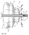
本発明のいくつかの実施形態は、左心耳(LAA)を機械的に閉鎖するための閉鎖デバイスを提供する。閉鎖デバイスは、液密バルーンチャンバーを規定するコンプライアントなバルーン、および(a)バルーンチャンバー内に少なくとも部分的に配置され、(b)バルーンの遠位端部分に接続され、(c)バルーンの遠位端部分と近位端部分との間の距離を設定するように、バルーンの近位端部分に対して長手方向に移動可能である、作動シャフトを含む。閉鎖デバイスはまた、バルーンチャンバーの膨張後に閉じることができる弁を含む。Some embodiments of the present invention provide a closure device for mechanically closing the left atrial appendage (LAA). The closure device includes a compliant balloon defining a fluid-tight balloon chamber, and an actuation shaft (a) at least partially disposed within the balloon chamber, (b) connected to a distal end portion of the balloon, and (c) longitudinally movable relative to the proximal end portion of the balloon to set a distance between the distal and proximal end portions of the balloon. The closure device also includes a valve that can be closed following inflation of the balloon chamber.
任意選択でそのストラットの塑性変形を含む、閉鎖デバイスの形状およびコンプライアント性は、閉鎖デバイスの固定およびLAAのシーリングを可能にすると同時に、LAAの幾何学的属性への適合および適応を可能にし、それによって、LAAの特定の形態タイプに関係なくLAAの空間を少なくともある程度充填する。The shape and compliance of the closure device, optionally including plastic deformation of its struts, allows the closure device to anchor and seal the LAA while simultaneously conforming and adapting to the geometric attributes of the LAA, thereby filling at least to some extent the LAA space regardless of the particular morphological type of the LAA.
さらに、LAAへのオーバー・ザ・ワイヤ係合、展開中の閉鎖デバイスの長さと向きの調整、および生理食塩水または別の充填液によるバルーンチャンバーの膨張を可能にするデリバリーシステムが提供される。Additionally, a delivery system is provided that allows for over-the-wire engagement into the LAA, adjustment of the length and orientation of the closure device during deployment, and inflation of the balloon chamber with saline or another filling fluid.
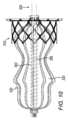
本明細書に記載の閉鎖デバイスは、長手方向に伸ばされ、全体的または部分的に圧縮された状態でLAAに送達されるように設計されている。送達後、閉鎖デバイスは、バルーンチャンバーを膨張させ、バルーンの近位端部分と遠位端部分との間に配列されたストラットの長手方向の寸法を短くすることによって、定着ゾーンの解剖学的構造に適応させられる。膨張による内圧の影響下で、バルーンチャンバーは特定の体積を占め、これにより、特定の長手方向のバルーン寸法に対して、特定の横方向または半径方向の寸法が得られ、バルーンとLAAの隣接する解剖学的構造との間に良好なシールが提供される。バルーンの遠位端部分と近位端部分との間の異なる距離を選択することによって、バルーンの長手方向の寸法を変更すると、バルーンの半径方向または横方向の延びの対応する変化が生じる。言い換えれば、バルーンの遠位端部分と近位端部分の間の距離を短くすると、他の点では一定の条件下で、半径方向または横方向の延びが対応して増加し、LAAの隣接組織とのシールが改善され、望ましくない血液の通過が抑制される。バルーンが必ずしも対称であるとは限らないため、および/またはバルーンが横方向に拡張される解剖学的構造が非対称のバルーン拡張を引き起こし得るため、バルーンの横方向の延びは必ずしも対称ではない。半径方向または横方向の拡張は、それらの範囲内に、バルーンの長手方向軸に対して概して垂直な1つ以上の方向を一緒に含む。The closure devices described herein are designed to be delivered to the LAA in a longitudinally stretched and fully or partially compressed state. After delivery, the closure device is adapted to the anatomy of the anchoring zone by inflating the balloon chamber and shortening the longitudinal dimension of the struts arranged between the proximal and distal end portions of the balloon. Under the influence of the internal pressure from the inflation, the balloon chamber occupies a certain volume, which results in a certain transverse or radial dimension for a certain longitudinal balloon dimension, providing a good seal between the balloon and the adjacent anatomy of the LAA. Changing the longitudinal dimension of the balloon by selecting a different distance between the distal and proximal end portions of the balloon results in a corresponding change in the radial or transverse extension of the balloon. In other words, shortening the distance between the distal and proximal end portions of the balloon, under otherwise constant conditions, results in a corresponding increase in the radial or transverse extension, improving the seal with the adjacent tissue of the LAA and inhibiting the passage of undesirable blood. The lateral extension of the balloon is not necessarily symmetrical because the balloon is not necessarily symmetrical and/or the anatomy through which the balloon is laterally expanded may cause asymmetric balloon expansion. Radial or lateral expansion together include within their scope one or more directions generally perpendicular to the longitudinal axis of the balloon.
本開示の文脈において、「遠位」および「近位」という用語は、経皮的心臓血管デバイスの分野におけるそれらの標準的な意味に従って使用される。「近位」という用語は、経皮送達中に送達カテーテルを追跡するときに、ユーザーによる操作のために構成されているカテーテルの端部(例えば、医師によって操作されるカテーテルハンドル)に近い、デバイスアセンブリの構成要素を指す。「遠位」という用語は、ユーザーによる操作のために構成されたカテーテルの端部からより離れている、かつ/または患者の体内により遠くに挿入されるデバイスアセンブリの構成要素を指すために使用される。In the context of this disclosure, the terms "distal" and "proximal" are used according to their standard meanings in the field of percutaneous cardiovascular devices. The term "proximal" refers to components of the device assembly that are closer to the end of the catheter configured for manipulation by the user (e.g., the catheter handle manipulated by the physician) when tracking the delivery catheter during percutaneous delivery. The term "distal" is used to refer to components of the device assembly that are further away from the end of the catheter configured for manipulation by the user and/or that are inserted further into the patient's body.
バルーンまたは構造部品に関連して本明細書で使用される「コンプライアント」という用語は、加えられた力に実質的に従う変形可能性を意味する。したがって、「コンプライアントなバルーン」とは、特定の破裂圧力を超えない限り、半径方向の圧力を増加させる効果の下で漸進的に膨張するバルーンを意味する。The term "compliant" as used herein in reference to a balloon or structural component means the ability to deform substantially in accordance with an applied force. Thus, a "compliant balloon" refers to a balloon that will progressively expand under the effect of increasing radial pressure, provided that a specified burst pressure is not exceeded.
本明細書で使用される場合、「ストラット」という用語は、形成することができる細長い構造要素、例えば、細いワイヤ、ロッド、または厚肉の管を意味し、これらはすべて、必ずしも円形の断面を有するとは限らない。As used herein, the term "strut" means an elongated structural element that can be formed, for example, of a thin wire, rod, or thick-walled tube, all of which do not necessarily have a circular cross section.
したがって、本発明の発明概念1に従って、左心耳(LAA)を閉鎖するための閉鎖デバイスであって、閉鎖デバイスは、送達システムとともに使用するためのものであり、閉鎖デバイスは、
液密バルーンチャンバーを規定するコンプライアントなバルーンと、
(a)バルーンチャンバー内に少なくとも部分的に配置され、(b)バルーンの遠位端部分に接続され、(c)バルーンの遠位端部分と近位端部分との間の距離を設定するように、バルーンの近位端部分に対して長手方向に移動可能である、作動シャフトと、
(a)半径方向に圧縮された状態および半径方向に拡張した状態を占めるように構成され、(b)フレームおよびフレームに固定されたカバーを含み、(c)半径方向に拡張した状態にあるとき、概して作動シャフトに直交し、10~50mmの、作動シャフトに垂直に測定された最大寸法を有する、近位LAA-オリフィスカバーと、
(a)近位LAA-オリフィスカバーに固定され、近位LAA-オリフィスカバーから遠位に延び、(b)半径方向に圧縮された状態および半径方向に拡張した状態を占めるように構成され、(c)半径方向に拡張した状態にあるとき概して円筒形である、オリフィス支持ステントと、を含む、閉鎖デバイスが提供される。 Thus, in accordance with an inventive concept 1 of the present invention, there is provided a closure device for closure of a left atrial appendage (LAA), the closure device being for use with a delivery system, the closure device comprising:
a compliant balloon defining a liquid-tight balloon chamber;
an actuation shaft (a) at least partially disposed within the balloon chamber, (b) connected to a distal end portion of the balloon, and (c) longitudinally movable relative to the proximal end portion of the balloon to set a distance between the distal and proximal end portions of the balloon;
(a) a proximal LAA-orifice cover configured to occupy a radially compressed state and a radially expanded state, (b) comprising a frame and a cover secured to the frame, and (c) when in the radially expanded state, generally orthogonal to the actuation shaft and having a maximum dimension measured perpendicular to the actuation shaft of 10 to 50 mm;
A closure device is provided that includes: (a) an orifice support stent secured to and extending distally from the proximal LAA-orifice cover; (b) configured to occupy a radially compressed state and a radially expanded state; and (c) a generally cylindrical shape when in the radially expanded state.
発明概念2.オリフィス支持ステントが、半径方向に拡張した状態にあるとき、(i)8~50mmの、作動シャフトに対して垂直に測定された最大寸法、および(ii)4~30mmの軸方向の長さを有する、発明概念1に記載の閉鎖デバイス。Inventive concept 2. A closure device as described in inventive concept 1, in which the orifice support stent, when in a radially expanded state, has (i) a maximum dimension measured perpendicular to the actuation shaft of 8 to 50 mm, and (ii) an axial length of 4 to 30 mm.
発明概念3.閉鎖デバイスは、バルーンの遠位端部分に配置された遠位先端をさらに含み、作動シャフトは遠位先端に接続されている、発明概念1に記載の閉鎖デバイス。Inventive concept 3. The closure device according to inventive concept 1, further comprising a distal tip disposed at the distal end portion of the balloon, the actuation shaft being connected to the distal tip.
発明概念4.作動シャフトが、バルーンの遠位端部分に配置された遠位先端を少なくとも部分的に規定するように形作られている、発明概念1に記載の閉鎖デバイス。Inventive concept 4. A closure device as described in inventive concept 1, wherein the actuation shaft is configured to at least partially define a distal tip disposed at the distal end portion of the balloon.
発明概念5.閉鎖デバイスは、バルーンの近位端部分に配置された近位基部をさらに含み、作動シャフトは、近位基部に対して移動可能である、発明概念1に記載の閉鎖デバイス。Inventive concept 5. The closure device of inventive concept 1, further comprising a proximal base disposed at the proximal end portion of the balloon, the actuation shaft being movable relative to the proximal base.
発明概念6.作動シャフトは、ガイドワイヤをその中にスライド可能に受け入れるためのガイドワイヤ管腔を規定するように形作られている、ガイドワイヤとともに使用するための、発明概念1に記載の閉鎖デバイス。Inventive concept 6. A closure device as described in inventive concept 1 for use with a guidewire, wherein the actuation shaft is configured to define a guidewire lumen for slidably receiving the guidewire therein.
発明概念7.コンプライアントなバルーンは、ポリカプロラクトン(PCL)、ポリグリコール酸(PGA)、ポリ乳酸(PLA)、およびポリジオキサノン(PDOまたはPDS)、シリコーン、ポリウレタン、ポリテトラフルオロエチレン(PTFE)、ポリメチルメタクリレート、ポリエーテルエーテルケトン(PEEK)、ポリ塩化ビニル、ポリエチレンテレフタレート、ナイロン、ポリアミド、ポリアミド、およびポリエーテルブロックアミド(PEBA)からなる群から選択されるコンプライアントな材料を含む、発明概念1に記載の閉鎖デバイス。Inventive concept 7. The closure device of inventive concept 1, wherein the compliant balloon comprises a compliant material selected from the group consisting of polycaprolactone (PCL), polyglycolic acid (PGA), polylactic acid (PLA), and polydioxanone (PDO or PDS), silicone, polyurethane, polytetrafluoroethylene (PTFE), polymethyl methacrylate, polyether ether ketone (PEEK), polyvinyl chloride, polyethylene terephthalate, nylon, polyamide, polyamide, and polyether block amide (PEBA).
発明概念8.オリフィス支持ステントは、バルーンの形状がオリフィス支持ステントの形状とは独立して変化することができるように、バルーンに固定されていない、発明概念1~7のいずれか1つに記載の閉鎖デバイス。Inventive concept 8. A closure device according to any one of inventive concepts 1 to 7, in which the orifice support stent is not fixed to the balloon such that the shape of the balloon can change independently of the shape of the orifice support stent.
発明概念9.バルーンチャンバーの膨張がオリフィス支持ステントをその半径方向に圧縮された状態からその半径方向に拡張した状態に移行させるように、閉鎖デバイスが構成されている、発明概念1~7のいずれか1つに記載の閉鎖デバイス。Inventive concept 9. A closure device according to any one of inventive concepts 1 to 7, wherein the closure device is configured such that inflation of the balloon chamber transitions the orifice support stent from its radially compressed state to its radially expanded state.
発明概念10.
閉鎖デバイスは、バルーンの近位端部分に対して軸方向に固定されている近位チューブをさらに含み、
近位LAA-オリフィスカバーは、近位チューブを半径方向で取り囲むように、近位チューブに固定され、近位チューブを介してバルーンに間接的に接続され、バルーンに直接接続されていない、発明概念1~7のいずれか1つに記載の閉鎖デバイス。
The closure device further includes a proximal tube axially secured to the proximal end portion of the balloon;
A closure device described in any one of inventive concepts 1 to 7, wherein the proximal LAA-orifice cover is fixed to the proximal tube so as to radially surround the proximal tube, and is indirectly connected to the balloon via the proximal tube, and is not directly connected to the balloon.
発明概念11.作動シャフトが近位チューブ内に部分的にスライド可能に配置されている、発明概念10に記載の閉鎖デバイス。Inventive concept 11. A closure device as described in
発明概念12.閉鎖デバイスは、バルーンの遠位端部分およびバルーンの近位端部分に固定された接続ストラットをさらに含む、発明概念1~7のいずれか1つに記載の閉鎖デバイス。Inventive concept 12. A closure device according to any one of inventive concepts 1 to 7, further comprising a connecting strut secured to the distal end portion of the balloon and the proximal end portion of the balloon.
発明概念13.閉鎖デバイスは、バルーンチャンバーの膨張が接続ストラットを塑性変形させるように構成されている、発明概念12に記載の閉鎖デバイス。Inventive concept 13. The closure device of inventive concept 12, wherein the closure device is configured such that inflation of the balloon chamber plastically deforms the connecting struts.
発明概念14.閉鎖デバイスは、バルーンの短縮が接続ストラットを塑性変形させるように構成されている、発明概念12に記載の閉鎖デバイス。Inventive concept 14. The closure device of inventive concept 12, wherein the closure device is configured such that shortening of the balloon plastically deforms the connecting struts.
発明概念15.バルーンが100~5000ミクロンの平均壁厚を有する、発明概念1~7のいずれか1つに記載の閉鎖デバイス。Inventive concept 15. A closure device according to any one of inventive concepts 1 to 7, wherein the balloon has an average wall thickness of 100 to 5000 microns.
発明概念16.バルーンは、バルーンの壁の最も薄い部分において、20~500ミクロンの間の最も薄い壁厚を有する、発明概念1~7のいずれか1つに記載の閉鎖デバイス。Inventive concept 16. A closure device according to any one of inventive concepts 1 to 7, wherein the balloon has a thinnest wall thickness of between 20 and 500 microns at the thinnest portion of the balloon wall.
発明概念17.発明概念1~7のいずれか1つに記載の閉鎖デバイスを含む閉鎖システムであって、閉鎖システムは、さらにインプラントカテーテルを含み、閉鎖デバイスは、半径方向に圧縮された状態で解放可能にインプラントカテーテル内に配置され、バルーンの近位端部分とバルーンの遠位端部分との間の最大距離が、8~80mmである、閉鎖システム。Inventive concept 17. A closure system including the closure device according to any one of inventive concepts 1 to 7, further including an implant catheter, the closure device being releasably disposed within the implant catheter in a radially compressed state, and the maximum distance between the proximal end portion of the balloon and the distal end portion of the balloon being 8 to 80 mm.
発明概念18.さらに弁を含む、発明概念1~7のいずれか1つに記載の閉鎖デバイス。Inventive concept 18. A closure device according to any one of inventive concepts 1 to 7, further comprising a valve.
発明概念19.
閉鎖デバイスは、流体流路を規定するように形作られており、
弁は、弁がそれぞれ開状態および閉状態にあるときに、流体流路とバルーンチャンバーとの間の流体の流れを選択的に許可または遮断するように構成されている、発明概念18に記載の閉鎖デバイス。
the closure device is configured to define a fluid flow path;
20. A closure device as defined in inventive concept 18, wherein the valve is configured to selectively allow or block fluid flow between the fluid flow path and the balloon chamber when the valve is in an open and closed state, respectively.
発明概念20.
閉鎖デバイスは、作動シャフトの部分に沿って流体流路を規定するように形作られており、
閉鎖デバイスは、ロック状態およびロック解除状態を占めるように構成されており、ロック状態にあるとき、バルーンの遠位端部分とバルーンの近位端部分との間に、作動シャフトを使用して設定された距離を維持するように構成されている、ロック機構をさらに含み、
閉鎖デバイスは、作動シャフトの近位方向の長手方向の動きによって、
(a)バルーンの遠位端部分と近位端部分との間の第1の所定の距離への距離の減少が、弁を自動的に開状態から閉状態に移行させ、
(b)バルーンの遠位端部分と近位端部分との間の第2の所定の距離への距離の減少が、ロック機構をロック解除状態からロック状態に自動的に移行させるように、構成されている、発明概念19に記載の閉鎖デバイス。
the closure device is configured to define a fluid flow path along a portion of the actuation shaft;
the closure device further includes a locking mechanism configured to assume a locked state and an unlocked state, and configured to maintain a distance between the distal end portion of the balloon and the proximal end portion of the balloon set using an actuation shaft when in the locked state;
The closure device is actuated by proximal longitudinal movement of the actuation shaft.
(a) a decrease in the distance between the distal end portion and the proximal end portion of the balloon to a first predetermined distance automatically transitions the valve from an open state to a closed state;
(b) a closure device as described in
発明概念21.閉鎖デバイスは、送達システムに解放可能に接続されるように構成されており、閉鎖デバイスは、閉鎖デバイスが送達システムに解放可能に接続されるとき流体流路が送達システムと流体連通して結合されるように、構成されている、発明概念20に記載の閉鎖デバイス。Inventive concept 21. A closure device according to
発明概念22.閉鎖デバイスは、閉鎖デバイスを送達システムの対応して構成された遠位コネクタに解放可能に接続するように構成されている近位コネクタをさらに含む、発明概念1に記載の閉鎖デバイス。Inventive concept 22. The closure device of inventive concept 1, further comprising a proximal connector configured to releasably connect the closure device to a correspondingly configured distal connector of the delivery system.
発明概念23.近位コネクタが、ねじ山を規定するように形作られている、発明概念22に記載の閉鎖デバイス。Inventive concept 23. A closure device as described in inventive concept 22, wherein the proximal connector is configured to define a thread.
発明概念24.発明概念22~23のいずれか1つに記載の閉鎖デバイスを含む閉鎖システムであって、閉鎖システムは、ガイドワイヤとともに使用するためのものであり、ガイドワイヤと協働する送達システムをさらに含み、送達システムは、操作ハンドルに接続されたインプラントカテーテルを含み、インプラントカテーテルは、ガイドワイヤのための長手方向通路と、インプラントカテーテルを閉鎖デバイスの対応して構成された近位コネクタに解放可能に接続するための遠位コネクタと、閉鎖デバイスの流体流路に解放可能に接続可能な膨張チューブチャネルとを含む、閉鎖システム。Inventive concept 24. A closure system including a closure device according to any one of inventive concepts 22-23, the closure system being for use with a guidewire and further including a delivery system cooperating with the guidewire, the delivery system including an implant catheter connected to an operating handle, the implant catheter including a longitudinal passage for the guidewire, a distal connector for releasably connecting the implant catheter to a correspondingly configured proximal connector of the closure device, and an inflation tube channel releasably connectable to a fluid flow path of the closure device.
さらに、本発明の発明概念25に従って、左心耳(LAA)を閉鎖するための閉鎖デバイスであって、閉鎖デバイスは送達システムとともに使用するためのものであり、閉鎖デバイスは、
液密バルーンチャンバーを規定するコンプライアントなバルーンと、
(a)バルーンチャンバー内に少なくとも部分的に配置され、(b)バルーンの遠位端部分に接続され、(c)バルーンの遠位端部分と近位端部分との間の距離を設定するように、バルーンの近位端部分に対して長手方向に移動可能である、作動シャフトと、
ロック状態およびロック解除状態を占めるように構成されており、ロック状態にあるとき、バルーンの遠位端部分とバルーンの近位端部分との間に、作動シャフトを使用して設定された距離を維持するように構成されている、ロック機構と、
弁と、を含み、
閉鎖デバイスは、作動シャフトの部分に沿った流体流路を規定するように形作られており、
弁は、弁がそれぞれ開状態および閉状態にあるときに、流体流路とバルーンチャンバーとの間の流体の流れを選択的に許可または遮断するように構成されており、
閉鎖デバイスは、作動シャフトの近位方向の長手方向の動きによって、
(a)バルーンの遠位端部分と近位端部分との間の第1の所定の距離への距離の減少が、弁を自動的に開状態から閉状態に移行させ、
(b)バルーンの遠位端部分と近位端部分との間の第2の所定の距離への距離の減少が、ロック機構をロック解除状態からロック状態に自動的に移行させるように、構成されている、閉鎖デバイスがさらに提供される。 Further in accordance with an inventive concept 25 of the present invention, there is provided a closure device for occluding a left atrial appendage (LAA), the closure device being for use with a delivery system, the closure device comprising:
a compliant balloon defining a liquid-tight balloon chamber;
an actuation shaft (a) at least partially disposed within the balloon chamber, (b) connected to a distal end portion of the balloon, and (c) longitudinally movable relative to the proximal end portion of the balloon to set a distance between the distal and proximal end portions of the balloon;
a locking mechanism configured to assume a locked state and an unlocked state, and configured to maintain a distance between the distal end portion of the balloon and the proximal end portion of the balloon, when in the locked state, set using an actuation shaft;
a valve;
the closure device is configured to define a fluid flow path along a portion of the actuation shaft;
the valve is configured to selectively allow or block fluid flow between the fluid flow path and the balloon chamber when the valve is in an open state and a closed state, respectively;
The closure device is actuated by proximal longitudinal movement of the actuation shaft.
(a) a decrease in the distance between the distal end portion and the proximal end portion of the balloon to a first predetermined distance automatically transitions the valve from an open state to a closed state;
(b) a closure device is further provided, wherein the closure device is configured such that a reduction in the distance between the distal end portion and the proximal end portion of the balloon to a second predetermined distance automatically transitions the locking mechanism from an unlocked state to a locked state.
発明概念26.第1の所定の距離が第2の所定の距離と等しくない、発明概念25に記載の閉鎖デバイス。
発明概念27.第1の所定の距離が第2の所定の距離よりも短い、発明概念26に記載の閉鎖デバイス。Inventive concept 27. A closure device as described in
発明概念28.第1の所定の距離が第2の所定の距離に等しい、発明概念25に記載の閉鎖デバイス。Inventive concept 28. A closure device as described in inventive concept 25, wherein the first predetermined distance is equal to the second predetermined distance.
発明概念29.閉鎖デバイスは、送達システムに解放可能に接続されるように構成されており、閉鎖デバイスは、閉鎖デバイスが送達システムに解放可能に接続されるとき流体流路が送達システムと流体連通して結合されるように、構成されている、発明概念25に記載の閉鎖デバイス。Inventive concept 29. A closure device according to inventive concept 25, wherein the closure device is configured to be releasably connected to the delivery system, and the closure device is configured such that the fluid flow path is coupled in fluid communication with the delivery system when the closure device is releasably connected to the delivery system.
発明概念30.閉鎖デバイスは、バルーンの遠位端部分に配置された遠位先端をさらに含み、作動シャフトは遠位先端に接続されている、発明概念25に記載の閉鎖デバイス。
発明概念31.作動シャフトが、バルーンの遠位端部分に配置された遠位先端を少なくとも部分的に規定するように形作られている、発明概念25に記載の閉鎖デバイス。Inventive concept 31. A closure device as described in inventive concept 25, wherein the actuation shaft is configured to at least partially define a distal tip disposed at a distal end portion of the balloon.
発明概念32.閉鎖デバイスは、バルーンの近位端部分に配置された近位基部をさらに含み、作動シャフトは、近位基部に対して移動可能である、発明概念25に記載の閉鎖デバイス。
発明概念33.作動シャフトは、ガイドワイヤをその中にスライド可能に受け入れるためのガイドワイヤ管腔を規定するように形作られている、ガイドワイヤとともに使用するための、発明概念25に記載の閉鎖デバイス。Inventive concept 33. A closure device as described in inventive concept 25 for use with a guidewire, wherein the actuation shaft is configured to define a guidewire lumen for slidably receiving the guidewire therein.
発明概念34.コンプライアントなバルーンは、ポリカプロラクトン(PCL)、ポリグリコール酸(PGA)、ポリ乳酸(PLA)、およびポリジオキサノン(PDOまたはPDS)、シリコーン、ポリウレタン、ポリテトラフルオロエチレン(PTFE)、ポリメチルメタクリレート、ポリエーテルエーテルケトン(PEEK)、ポリ塩化ビニル、ポリエチレンテレフタレート、ナイロン、ポリアミド、ポリアミド、およびポリエーテルブロックアミド(PEBA)からなる群から選択されるコンプライアントな材料を含む、発明概念25に記載の閉鎖デバイス。
発明概念35.閉鎖デバイスが、作動シャフトの部分に沿った流体流路を規定するように形作られている、発明概念25~34のいずれか1つに記載の閉鎖デバイス。Inventive concept 35. A closure device according to any one of inventive concepts 25-34, wherein the closure device is configured to define a fluid flow path along a portion of the actuation shaft.
発明概念36.弁が作動シャフトに沿って配置されている、発明概念25~34のいずれか1つに記載の閉鎖デバイス。
発明概念37.閉鎖デバイスは、バルーンの近位端部分に対して軸方向に固定されている近位チューブをさらに含み、作動シャフトが、近位チューブ内に部分的にスライド可能に配置されている、発明概念25~34のいずれか1つに記載の閉鎖デバイス。Inventive concept 37. The closure device according to any one of inventive concepts 25 to 34, further comprising a proximal tube axially fixed to the proximal end portion of the balloon, the actuation shaft being partially slidably disposed within the proximal tube.
発明概念38.閉鎖デバイスは、半径方向で作動シャフトの外面と近位チューブの内面との間に作動シャフトの部分に沿って流体流路を規定するように形作られている、発明概念37に記載の閉鎖デバイス。
発明概念39.弁が作動シャフトに沿って配置されている、発明概念38に記載の閉鎖デバイス。Inventive concept 39. A closure device as described in
発明概念40.弁が、作動シャフトの外面の少なくとも部分の周りにシールを含み、弁は、シールが近位チューブに対して1つ以上の第1の軸方向位置に配置されるとき開状態を占め、シールが近位チューブに対して1つ以上の第2の軸方向位置に配置されるとき閉状態を占めるように構成されており、1つ以上の第2の軸方向位置は1つ以上の第1の軸方向位置の近位にある、発明概念39に記載の閉鎖デバイス。
発明概念41.シール、作動シャフト、および近位チューブが、少なくともシールが近位チューブに対して1つ以上の第1の軸方向位置に配置されるとき近位チューブの遠位端からの流体流を遮断するように配列されている、発明概念40に記載の閉鎖デバイス。Inventive concept 41. A closure device as described in
発明概念42.近位チューブの壁が、壁を通る1つ以上のタブを規定するように形作られており、1つ以上のタブが半径方向内側に屈曲するようにバイアスされ、弁が開状態にあるとき、流体流路は、1つ以上のタブのそれぞれの近位端と、1つ以上のタブに軸方向に隣接する壁のタブのない部分との間で壁を通過する、発明概念38に記載の閉鎖デバイス。Inventive concept 42. A closure device as described in
発明概念43.壁のタブのない部分が、1つ以上のタブの近位に配置されている、発明概念42に記載の閉鎖デバイス。Inventive concept 43. A closure device as described in inventive concept 42, wherein the tab-free portion of the wall is disposed proximal to one or more tabs.
発明概念44.作動シャフトの外面が、作動シャフトの少なくとも部分の周りに1つ以上の突起を規定するように形作られており、1つ以上のタブの近位端は、1つ以上の突起が1つ以上のタブの近位端の近位に配置されたときに1つ以上の突起の遠位移動を防ぎ、それによってロック機構がロック状態を占めるように形作られている、発明概念42に記載の閉鎖デバイス。
発明概念45.閉鎖デバイスが、近位LAA-オリフィスカバーをさらに含み、近位LAA-オリフィスカバーは、(a)近位チューブを半径方向で取り囲んで近位チューブに固定され、(b)半径方向に圧縮された状態および半径方向に拡張した状態を占めるように構成されており、(c)フレームと、フレームに固定されたカバーとを含み、(d)半径方向に拡張した状態において、概して近位チューブに直交し、10~50mmの、近位チューブに垂直に測定された最大寸法を有し、(e)近位チューブを介してバルーンに間接的に接続されており、バルーンに直接接続されていない、発明概念37に記載の閉鎖デバイス。Inventive concept 45. The closure device of inventive concept 37, further comprising a proximal LAA-orifice cover, the proximal LAA-orifice cover (a) radially surrounds and is secured to the proximal tube, (b) is configured to occupy a radially compressed state and a radially expanded state, (c) comprises a frame and a cover secured to the frame, (d) in the radially expanded state has a maximum dimension measured perpendicular to the proximal tube generally perpendicular to the proximal tube of 10-50 mm, and (e) is indirectly connected to the balloon via the proximal tube and is not directly connected to the balloon.
発明概念46.閉鎖デバイスが、(a)近位LAA-オリフィスカバーに固定され、近位LAA-オリフィスカバーから遠位に延び、(b)半径方向に圧縮された状態および半径方向に拡張した状態を占めるように構成されており、(c)半径方向に拡張した状態にあるとき概して円筒形である、オリフィス支持ステントをさらに含む、発明概念45に記載の閉鎖デバイス。
発明概念47.オリフィス支持ステントが、半径方向に拡張した状態にあるとき、(i)8~50mmの、作動シャフトに対して垂直に測定された最大寸法、および(ii)4~30mmの軸方向の長さを有する、発明概念46に記載の閉鎖デバイス。Inventive concept 47. A closure device as described in
発明概念48.閉鎖デバイスは、バルーンの遠位端部分およびバルーンの近位端部分に固定された接続ストラットをさらに含む、発明概念25~34のいずれか1つに記載の閉鎖デバイス。
発明概念49.閉鎖デバイスは、バルーンチャンバーの膨張が接続ストラットを塑性変形させるように構成されている、発明概念48に記載の閉鎖デバイス。Inventive concept 49. The closure device of
発明概念50.閉鎖デバイスは、バルーンの短縮が接続ストラットを塑性変形させるように構成されている、発明概念48に記載の閉鎖デバイス。
発明概念51.バルーンが100~5000ミクロンの平均壁厚を有する、発明概念25~34のいずれか1つに記載の閉鎖デバイス。Inventive concept 51. A closure device according to any one of inventive concepts 25 to 34, wherein the balloon has an average wall thickness of 100 to 5000 microns.
発明概念52.バルーンは、バルーンの壁の最も薄い部分において、20~500ミクロンの間の最も薄い壁厚を有する、発明概念25~34のいずれか1つに記載の閉鎖デバイス。
発明概念53.発明概念25~34のいずれか1つに記載の閉鎖デバイスを含む閉鎖システムであって、閉鎖システムは、さらにインプラントカテーテルを含み、閉鎖デバイスは、半径方向に圧縮された状態で解放可能にインプラントカテーテル内に配置され、バルーンの近位端部分とバルーンの遠位端部分との間の最大距離が、8~80mmである、閉鎖システム。Inventive concept 53. A closure system including a closure device according to any one of inventive concepts 25 to 34, further including an implant catheter, the closure device being releasably disposed within the implant catheter in a radially compressed state, and the maximum distance between the proximal end portion of the balloon and the distal end portion of the balloon being 8 to 80 mm.
発明概念54.閉鎖デバイスは、閉鎖デバイスを送達システムの対応して構成された遠位コネクタに解放可能に接続するように構成されている近位コネクタをさらに含む、発明概念25~34のいずれか1つに記載の閉鎖デバイス。
発明概念55.近位コネクタが、ねじ山を規定するように形作られている、発明概念54に記載の閉鎖デバイス。Inventive concept 55. A closure device as described in
発明概念56.発明概念25~34のいずれか1つに記載の閉鎖デバイスを含む閉鎖システムであって、閉鎖システムは、ガイドワイヤとともに使用するためのものであり、ガイドワイヤと協働する送達システムをさらに含み、送達システムは、操作ハンドルに接続されたインプラントカテーテルを含み、インプラントカテーテルは、ガイドワイヤのための長手方向通路と、インプラントカテーテルを閉鎖デバイスの対応して構成された近位コネクタに解放可能に接続するための遠位コネクタと、閉鎖デバイスの流体流路に解放可能に接続可能な膨張チューブチャネルとを含む、閉鎖システム。Inventive concept 56. A closure system including a closure device according to any one of inventive concepts 25-34, the closure system being for use with a guidewire and further including a delivery system cooperating with the guidewire, the delivery system including an implant catheter connected to an operating handle, the implant catheter including a longitudinal passage for the guidewire, a distal connector for releasably connecting the implant catheter to a correspondingly configured proximal connector of the closure device, and an inflation tube channel releasably connectable to a fluid flow path of the closure device.
さらに、本発明の発明概念57に従って、左心耳(LAA)を閉鎖するための閉鎖デバイスであって、閉鎖デバイスは送達システムとともに使用するためのものであり、閉鎖デバイスは、
液密バルーンチャンバーを規定するコンプライアントなバルーンと、
(a)バルーンチャンバー内に少なくとも部分的に配置され、(b)バルーンの遠位端部分に接続され、(c)バルーンの遠位端部分と近位端部分との間の距離を設定するように、バルーンの近位端部分に対して長手方向に移動可能である、作動シャフトと、
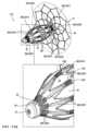
バルーンの遠位端部分およびバルーンの近位端部分に固定された接続ストラットであって、接続ストラットは、
バルーンの側面に沿って配列された第1の側面部分、
バルーンの遠位面に配列された第2の遠位端部分、
バルーンの近位面に配列された第3の近位端部分、および
ストラットの第2の遠位端部分をそれぞれバルーンの遠位端部分に結合し、曲がりくねった形状を有する遠位端部分であって、閉鎖デバイスは、バルーンチャンバーの膨張時に遠位端部分が湾曲されるように構成される、遠位端部分を含む、接続ストラットと、を含む、閉鎖デバイスがさらに提供される。 Further in accordance with an inventive concept 57 of the present invention, there is provided a closure device for occluding a left atrial appendage (LAA), the closure device being for use with a delivery system, the closure device comprising:
a compliant balloon defining a liquid-tight balloon chamber;
an actuation shaft (a) at least partially disposed within the balloon chamber, (b) connected to a distal end portion of the balloon, and (c) longitudinally movable relative to the proximal end portion of the balloon to set a distance between the distal and proximal end portions of the balloon;
a connecting strut secured to the distal end portion of the balloon and to the proximal end portion of the balloon, the connecting strut comprising:
a first side portion arranged along a side of the balloon;
a second distal end portion disposed on a distal surface of the balloon;
A closure device is further provided that includes a connecting strut including a third proximal end portion arranged on the proximal surface of the balloon, and a distal end portion coupling each of the second distal end portions of the strut to the distal end portion of the balloon and having a serpentine shape, wherein the closure device is configured such that the distal end portion is curved upon inflation of the balloon chamber.
発明概念58.接続ストラットが、ストラットの第3の近位端部分をそれぞれバルーンの近位端部分に結合し、曲がりくねった形状を有する近位端部分を含み、閉鎖デバイスは、バルーンチャンバーの膨張時に近位端部分が湾曲されるように構成されている、発明概念57に記載の閉鎖デバイス。
発明概念59.接続ストラットが、それぞれ第1の側方部分および第2の遠位端部分を結合し、曲がりくねった形状を有する遠位インターフェース部分を含み、閉鎖デバイスは、バルーンチャンバーの膨張時に遠位インターフェース部分が湾曲されるように構成されている、発明概念57に記載の閉鎖デバイス。Inventive concept 59. A closure device according to inventive concept 57, wherein the connecting struts each join the first lateral portion and the second distal end portion and include a distal interface portion having a serpentine shape, and the closure device is configured such that the distal interface portion is curved upon inflation of the balloon chamber.
発明概念60.接続ストラットが、それぞれ第1の側方部分および第3の近位端部分を結合し、曲がりくねった形状を有する近位インターフェース部分を含み、閉鎖デバイスは、バルーンチャンバーの膨張時に近位インターフェース部分が湾曲されるように構成されている、発明概念57に記載の閉鎖デバイス。
発明概念61.ストラットの第1の側方部分が概して真っ直ぐである、発明概念57に記載の閉鎖デバイス。Inventive concept 61. A closure device as described in inventive concept 57, wherein the first lateral portion of the strut is generally straight.
発明概念62.第2の遠位端部分および第3の近位端部分が概して真っ直ぐである、発明概念57に記載の閉鎖デバイス。
発明概念63.ストラットの第1の側方部分は概して真っ直ぐであり、第2の遠位端部分および第3の近位端部分は概して真っ直ぐである、発明概念57に記載の閉鎖デバイス。Inventive concept 63. A closure device as described in inventive concept 57, wherein the first lateral portion of the strut is generally straight and the second distal end portion and the third proximal end portion are generally straight.
発明概念64.閉鎖デバイスは、バルーンチャンバーの膨張が接続ストラットを塑性変形させるように構成されている、発明概念57に記載の閉鎖デバイス。
発明概念65.閉鎖デバイスは、バルーンの短縮が接続ストラットを塑性変形させるように構成されている、発明概念57に記載の閉鎖デバイス。Inventive concept 65. The closure device of inventive concept 57, wherein the closure device is configured such that shortening of the balloon plastically deforms the connecting struts.
発明概念66.
遠位インターフェース部分は、それらの間にそれぞれの狭い細長いギャップを規定する、平行な曲がりくねったストラットのそれぞれの対を規定するように形作られており、
ストラットは、複数のスパイクを規定するように形作られており、複数のスパイクは、
それぞれ、第2の遠位端部分の外端から延び、
バルーンが膨張していない細長い構成にある場合、概して軸方向に配向された、それぞれの狭い細長いギャップに配置され、
バルーンチャンバーの膨張時にさらに半径方向に延びて、組織に係合する棘として機能するように構成されている、発明概念57~65のいずれか1つに記載の閉鎖デバイス。
the distal interface portion is shaped to define respective pairs of parallel serpentine struts defining respective narrow elongated gaps therebetween;
The struts are shaped to define a plurality of spikes, the plurality of spikes comprising:
each extending from an outer end of the second distal end portion;
When the balloons are in an uninflated elongated configuration, the balloons are disposed in respective narrow elongated gaps that are generally axially oriented;
A closure device according to any one of inventive concepts 57-65, configured to extend further radially upon inflation of the balloon chamber to function as barbs to engage tissue.
発明概念67.接続ストラットは、第1の側方部分の隣接する対を接続する閉じたステントセルをさらに含む、発明概念57~65のいずれか1つに記載の閉鎖デバイス。Inventive concept 67. A closure device according to any one of inventive concepts 57-65, wherein the connecting strut further comprises a closed stent cell connecting adjacent pairs of the first lateral portions.
発明概念68.直列に配列された2つ以上の閉じたステントセルが第1の側方部分の隣接する対を接続する、発明概念67に記載の閉鎖デバイス。Inventive concept 68. An occlusion device as described in inventive concept 67, in which two or more closed stent cells arranged in series connect adjacent pairs of the first side portions.
発明概念69.閉じたステントセルがそれぞれのひし形として形作られている、発明概念67に記載の閉鎖デバイス。Inventive concept 69. A closure device as described in inventive concept 67, wherein the closed stent cells are shaped as respective diamonds.
発明概念70.第1の側方部分が閉鎖デバイスの中心長手方向軸に平行に配向されている、発明概念67に記載の閉鎖デバイス。
発明概念71.第1の側方部分のストラットの平均幅が、閉じたステントセルのストラットの平均幅の少なくとも200%に等しい、発明概念67に記載の閉鎖デバイス。Inventive concept 71. A closure device as described in inventive concept 67, wherein the average width of the struts of the first lateral portion is at least 200% of the average width of the struts of the closed stent cells.
さらに、本発明の発明概念72に従って、左心耳(LAA)を閉鎖するための閉鎖デバイスであって、閉鎖デバイスは送達システムとともに使用するためのものであり、閉鎖デバイスは、
液密バルーンチャンバーを規定するコンプライアントなバルーンと、
(a)バルーンチャンバー内に少なくとも部分的に配置され、(b)バルーンの遠位端部分に接続され、(c)バルーンの遠位端部分と近位端部分との間の距離を設定するように、バルーンの近位端部分に対して長手方向に移動可能である、作動シャフトと、
バルーンの遠位端部分およびバルーンの近位端部分に固定された接続ストラットであって、接続ストラットは、
バルーンの側面に沿って配列された第1の側面部分、
バルーンの遠位面に配列された第2の遠位端部分、
バルーンの近位面に配列された第3の近位端部分、および
それぞれ第1の側方部分および第2の遠位端部分を結合し、曲がりくねった形状を有する遠位インターフェース部分であって、閉鎖デバイスは、バルーンチャンバーの膨張時に遠位インターフェース部分が湾曲するように構成されている、遠位インターフェース部分を含む、接続ストラットと、を含む閉鎖デバイスが提供される。 Further in accordance with an
a compliant balloon defining a liquid-tight balloon chamber;
an actuation shaft (a) at least partially disposed within the balloon chamber, (b) connected to a distal end portion of the balloon, and (c) longitudinally movable relative to the proximal end portion of the balloon to set a distance between the distal and proximal end portions of the balloon;
a connecting strut secured to the distal end portion of the balloon and to the proximal end portion of the balloon, the connecting strut comprising:
a first side portion arranged along a side of the balloon;
a second distal end portion disposed on a distal surface of the balloon;
a third proximal end portion arranged on a proximal surface of the balloon; and a connecting strut including a distal interface portion joining the first lateral portion and the second distal end portion, respectively, and having a serpentine shape, wherein the closure device is configured such that the distal interface portion curves upon inflation of the balloon chamber.
発明概念73.接続ストラットが、それぞれ第1の側方部分および第3の近位端部分を結合し、曲がりくねった形状を有する近位インターフェース部分を含み、閉鎖デバイスは、バルーンチャンバーの膨張時に近位インターフェース部分が湾曲されるように構成されている、発明概念72に記載の閉鎖デバイス。Inventive concept 73. A closure device according to
発明概念74.ストラットの第1の側方部分が概して真っ直ぐである、発明概念72に記載の閉鎖デバイス。
発明概念75.第2の遠位端部分および第3の近位端部分が概して真っ直ぐである、発明概念72に記載の閉鎖デバイス。Inventive concept 75. A closure device as described in
発明概念76.ストラットの第1の側方部分は概して真っ直ぐであり、第2の遠位端部分および第3の近位端部分は概して真っ直ぐである、発明概念72に記載の閉鎖デバイス。
発明概念77.閉鎖デバイスは、バルーンチャンバーの膨張が接続ストラットを塑性変形させるように構成される、発明概念72に記載の閉鎖デバイス。Inventive concept 77. The closure device of
発明概念78.閉鎖デバイスは、バルーンの短縮が接続ストラットを塑性変形させるように構成されている、発明概念72に記載の閉鎖デバイス。Inventive concept 78. The closure device of
発明概念79.接続ストラットが、ストラットの第2の遠位端部分をそれぞれバルーンの遠位端部分に結合し、曲がりくねった形状を有する遠位端部分を含み、閉鎖デバイスは、バルーンチャンバーの膨張時に遠位端部分が湾曲されるように構成されている、発明概念72に記載の閉鎖デバイス。Inventive concept 79. A closure device according to
発明概念80.接続ストラットが、ストラットの第3の近位端部分をそれぞれバルーンの近位端部分に結合し、曲がりくねった形状を有する近位端部分を含み、閉鎖デバイスは、バルーンチャンバーの膨張時に近位端部分が湾曲されるように構成されている、発明概念72に記載の閉鎖デバイス。
発明概念81.
遠位インターフェース部分は、それらの間にそれぞれの狭い細長いギャップを規定する、平行な曲がりくねったストラットのそれぞれの対を規定するように形作られており、
ストラットは、複数のスパイクを規定するように形作られており、複数のスパイクは、
それぞれ、第2の遠位端部分の外端から延び、
バルーンが膨張していない細長い構成にある場合、概して軸方向に配向された、それぞれの狭い細長いギャップに配置され、
バルーンチャンバーの膨張時にさらに半径方向に延びて、組織に係合する棘として機能するように構成されている、発明概念72~80のいずれか1つに記載の閉鎖デバイス。 Inventive concept 81.
the distal interface portion is shaped to define respective pairs of parallel serpentine struts defining respective narrow elongated gaps therebetween;
The struts are shaped to define a plurality of spikes, the plurality of spikes comprising:
each extending from an outer end of the second distal end portion;
When the balloons are in an uninflated elongated configuration, the balloons are disposed in respective narrow elongated gaps that are generally axially oriented;
A closure device according to any one of inventive concepts 72-80, configured to extend further radially upon inflation of the balloon chamber to function as barbs to engage tissue.
発明概念82.接続ストラットは、第1の側方部分の隣接する対を接続する閉じたステントセルをさらに含む、発明概念72~80のいずれか1つに記載の閉鎖デバイス。
発明概念83.直列に配列された2つ以上の閉じたステントセルが第1の側方部分の隣接する対を接続する、発明概念82に記載の閉鎖デバイス。Inventive concept 83. An occlusion device as described in
発明概念84.閉じたステントセルがそれぞれのひし形として形作られている、発明概念82に記載の閉鎖デバイス。
発明概念85.第1の側方部分が閉鎖デバイスの中心長手方向軸に平行に配向されている、発明概念82に記載の閉鎖デバイス。Inventive concept 85. A closure device as described in
発明概念86.第1の側方部分のストラットの平均幅が、閉じたステントセルのストラットの平均幅の少なくとも200%に等しい、発明概念82に記載の閉鎖デバイス。
さらに、本発明の発明概念87に従って、左心耳(LAA)を閉鎖するための閉鎖デバイスであって、閉鎖デバイスは送達システムとともに使用するためのものであり、閉鎖デバイスは、
液密バルーンチャンバーを規定するコンプライアントなバルーンと、
(a)バルーンチャンバー内に少なくとも部分的に配置され、(b)バルーンの遠位端部分に接続され、(c)バルーンの遠位端部分と近位端部分との間の距離を設定するように、バルーンの近位端部分に対して長手方向に移動可能である、作動シャフトと、
バルーンの遠位端部分およびバルーンの近位端部分に固定された接続ストラットであって、接続ストラットは、
バルーンの側面に沿って配列された第1の側面部分、および
第1の側面部分の隣接する対を接続する閉じたステントセルを含む、接続ストラットと、を含む閉鎖デバイスが提供される。 Further in accordance with the present inventive concept 87, there is provided a closure device for occluding a left atrial appendage (LAA), the closure device being for use with a delivery system, the closure device comprising:
a compliant balloon defining a liquid-tight balloon chamber;
an actuation shaft (a) at least partially disposed within the balloon chamber, (b) connected to a distal end portion of the balloon, and (c) longitudinally movable relative to the proximal end portion of the balloon to set a distance between the distal and proximal end portions of the balloon;
a connecting strut secured to the distal end portion of the balloon and to the proximal end portion of the balloon, the connecting strut comprising:
An occlusion device is provided that includes first side portions arranged along a side of the balloon; and a connecting strut including closed stent cells connecting adjacent pairs of the first side portions.
発明概念88.直列に配列された2つ以上の閉じたステントセルが第1の側方部分の隣接する対を接続する、発明概念87に記載の閉鎖デバイス。
発明概念89.閉じたステントセルがそれぞれのひし形として形作られている、発明概念87に記載の閉鎖デバイス。
発明概念90.第1の側方部分が閉鎖デバイスの中心長手方向軸に平行に配向されている、発明概念87に記載の閉鎖デバイス。Inventive concept 90. A closure device as described in inventive concept 87, wherein the first lateral portion is oriented parallel to a central longitudinal axis of the closure device.
発明概念91.第1の側方部分のストラットの平均幅が、閉じたステントセルのストラットの平均幅の少なくとも200%に等しい、発明概念87に記載の閉鎖デバイス。Inventive concept 91. A closure device as described in inventive concept 87, wherein the average width of the struts of the first lateral portion is at least 200% of the average width of the struts of the closed stent cells.
本発明の発明概念92に従って、患者の左心耳(LAA)を閉鎖するための方法であって、方法は、
送達システムを使用して、
閉鎖デバイスのコンプライアントなバルーンをその長手方向に延びた形態でLAAに位置決めすることと、
閉鎖デバイスの作動シャフトをLAAに位置決めすることであって、作動シャフトは、(a)バルーンチャンバー内に少なくとも部分的に配置され、(b)バルーンの遠位端部分に接続され、(c)バルーンの遠位端部分と近位端部分との間の距離を設定するように、バルーンの近位端部分に対して長手方向に移動可能である、位置決めすることと、
近位LAA-オリフィスカバーをLAAの外側で左心室に、LAAのオリフィスを取り囲む心房壁に対して位置決めすることであって、近位LAA-オリフィスカバーは、(a)半径方向に圧縮された状態および半径方向に拡張した状態を占めるように構成されており、(b)フレームおよびフレームに固定されたカバーを含み、(c)半径方向に拡張した状態にあるとき、概して作動シャフトに直交し、10~50mmの、作動シャフトに垂直に測定された最大寸法を有する、位置決めすることと、
オリフィス支持ステントを少なくとも部分的にLAAに位置決めすることであって、オリフィス支持ステントは、(a)近位LAA-オリフィスカバーに固定され、近位LAA-オリフィスカバーから遠位に延び、(b)半径方向に圧縮された状態および半径方向に拡張した状態を占めるように構成されており、(c)半径方向に拡張した状態にあるとき概して円筒形である、位置決めすることと、
作動シャフトの部分に沿った流体流路を介してバルーンチャンバーに流体を充填することにより、コンプライアントなバルーンを膨張させることと、
バルーンの遠位端部分と近位端部分との間の距離を所望の距離に短縮することにより、バルーンを半径方向または横方向に拡張させることと、
閉鎖デバイスを送達システムから解放することと、を含む、方法もまた提供される。 In accordance with the inventive concept 92 of the present invention, there is provided a method for closing a left atrial appendage (LAA) of a patient, the method comprising:
Using a delivery system
Positioning a compliant balloon of a closure device in its longitudinally extended configuration in the LAA;
positioning an actuation shaft of a closure device in the LAA, the actuation shaft (a) being at least partially disposed within the balloon chamber, (b) being connected to a distal end portion of the balloon, and (c) being longitudinally movable relative to the proximal end portion of the balloon to set a distance between the distal and proximal end portions of the balloon;
Positioning a proximal LAA-orifice cover in the left ventricle outside the LAA against an atrial wall surrounding an orifice of the LAA, the proximal LAA-orifice cover (a) configured to occupy a radially compressed state and a radially expanded state, (b) including a frame and a cover secured to the frame, and (c) when in the radially expanded state, generally orthogonal to the working shaft and having a maximum dimension measured perpendicular to the working shaft of 10 to 50 mm;
positioning an orifice support stent at least partially in the LAA, the orifice support stent (a) secured to and extending distally from the proximal LAA-orifice cover, (b) configured to occupy a radially compressed state and a radially expanded state, and (c) being generally cylindrical when in the radially expanded state;
Inflating a compliant balloon by filling a balloon chamber with fluid via a fluid passage along a portion of the actuation shaft;
radially or laterally expanding the balloon by shortening the distance between the distal and proximal end portions of the balloon to a desired distance;
and releasing the closure device from the delivery system.
発明概念93.オリフィス支持ステントは、バルーンの形状が、オリフィス支持ステントの形状とは独立して変化することができるように、バルーンに固定されていない、発明概念92に記載の方法。Inventive concept 93. The method of inventive concept 92, wherein the orifice support stent is not fixed to the balloon such that the shape of the balloon can change independently of the shape of the orifice support stent.
発明概念94.コンプライアントなバルーンを膨張させることにより、オリフィス支持ステントをその半径方向に圧縮された状態からその半径方向に拡張した状態に移行させる、発明概念92に記載の方法。Inventive concept 94. A method according to inventive concept 92, in which the orifice support stent is transitioned from its radially compressed state to its radially expanded state by inflating a compliant balloon.
本発明の発明概念95に従って、患者の左心耳(LAA)を閉鎖するための方法であって、方法は、
送達システムを使用して、閉鎖デバイスのコンプライアントなバルーンをその長手方向に延びた形態でLAAに位置決めすることと、
閉鎖デバイスの弁が、弁が流体流路とバルーンチャンバーとの間の流体の流れを許可する開状態にあるときに、閉鎖デバイスの作動シャフトの部分に沿った流体流路を介して、バルーンによって規定された液密バルーンチャンバー内に流体を充填することによって、コンプライアントなバルーンを膨張させることであって、作動シャフトは、(a)少なくとも部分的にバルーンチャンバー内に配置され、(b)バルーンの遠位端部分に接続され、(c)バルーンの遠位端部分と近位端部分との間の距離を設定するようにバルーンの近位端部分に対して長手方向に移動可能である、膨張させることと、
作動シャフトを近位方向に長手方向に、
(a)バルーンの遠位端部分と近位端部分との間の第1の所定の距離であって、弁を自動的に開状態から、弁が流体流路とバルーンチャンバーとの間の流体流を遮断する閉状態へ移行させる、第1の所定の距離に、かつ
(b)バルーンの遠位端部分と近位端部分との間の第2の所定の距離であって、ロッキング機構をロック解除状態から、ロッキング機構がバルーンの遠位端部分とバルーンの近位端部分との間で作動シャフトを使用して設定された距離を維持するロックされた状態に自動的に移行させる、第2の所定の距離に動かすことによって、バルーンの遠位端部分と近位端部分との間の距離を所望の距離に短縮することによってバルーンを半径方向または横方向に拡張させることと、
閉鎖デバイスを送達システムから解放することと、を含む、方法がさらに提供される。 In accordance with the inventive concept 95 of the present invention, there is provided a method for closing a left atrial appendage (LAA) of a patient, the method comprising:
positioning a compliant balloon of a closure device in its longitudinally extended configuration in the LAA using a delivery system;
inflating a compliant balloon by filling a fluid into a liquid-tight balloon chamber defined by the balloon through a fluid flow path along a portion of an actuation shaft of the closure device when a valve of the closure device is in an open state permitting fluid flow between the fluid flow path and the balloon chamber, the actuation shaft (a) being at least partially disposed within the balloon chamber, (b) being connected to a distal end portion of the balloon, and (c) being longitudinally movable relative to the proximal end portion of the balloon to set a distance between the distal and proximal end portions of the balloon;
The actuation shaft is longitudinally rotated proximally.
radially or laterally expanding the balloon by shortening the distance between the distal and proximal end portions of the balloon to a desired distance by (a) moving a first predetermined distance between the distal and proximal end portions of the balloon, the first predetermined distance causing the valve to automatically transition from an open state to a closed state in which the valve blocks fluid flow between the fluid flow path and the balloon chamber, and (b) moving a second predetermined distance between the distal and proximal end portions of the balloon, the second predetermined distance causing a locking mechanism to automatically transition from an unlocked state to a locked state in which the locking mechanism maintains a distance set using an actuation shaft between the distal end portion of the balloon and the proximal end portion of the balloon;
Releasing the closure device from the delivery system is further provided.
発明概念96.バルーンをLAAに位置決めすることは、
送達システムを使用してガイドワイヤを患者の体内に前進させることと、
ガイドワイヤ上で閉鎖デバイスを前進させることと、を含む、発明概念95に記載の方法。 Inventive concept 96. Positioning the balloon in the LAA comprises:
advancing a guidewire into a patient using a delivery system;
A method according to inventive concept 95, comprising advancing a closure device over the guidewire.
発明概念97.第1の所定の距離が、第2の所定の距離と等しくない、発明概念95に記載の方法。Inventive concept 97. A method according to inventive concept 95, wherein the first predetermined distance is not equal to the second predetermined distance.
発明概念98.第1の所定の距離が、第2の所定の距離よりも短い、発明概念97に記載の方法。Inventive concept 98. A method according to inventive concept 97, wherein the first predetermined distance is less than the second predetermined distance.
発明概念99.第1の所定の距離が、第2の所定の距離に等しい、発明概念95に記載の方法。Inventive concept 99. A method according to inventive concept 95, wherein the first predetermined distance is equal to the second predetermined distance.
発明概念100.閉鎖デバイスが、作動シャフトの部分に沿った流体流路を規定するように形作られている、発明概念95に記載の方法。
発明概念101.弁が、作動シャフトに沿って配置されている、発明概念95に記載の方法。Inventive concept 101. The method of inventive concept 95, wherein the valve is disposed along the actuation shaft.
発明概念102.閉鎖デバイスが、バルーンの近位端部分に対して軸方向に固定されている近位チューブをさらに含み、作動シャフトが、近位チューブ内に部分的にスライド可能に配置されている、発明概念95に記載の方法。
発明概念103.閉鎖デバイスは、半径方向で作動シャフトの外面と近位チューブの内面との間に作動シャフトの部分に沿って流体流路を規定するように形作られている、発明概念102に記載の方法。Inventive concept 103. The method of
発明概念104.弁が、作動シャフトに沿って配置されている、発明概念103に記載の方法。Inventive concept 104. The method of inventive concept 103, wherein the valve is disposed along the actuation shaft.
発明概念105.弁が、作動シャフトの外面の少なくとも部分の周りにシールを含み、弁は、シールが近位チューブに対して1つ以上の第1の軸方向位置に配置されるとき開状態を占め、シールが近位チューブに対して1つ以上の第2の軸方向位置に配置されるとき閉状態を占めるように構成され、1つ以上の第2の軸方向位置は1つ以上の第1の軸方向位置の近位にある、発明概念104に記載の方法。Inventive concept 105. A method according to inventive concept 104, wherein the valve includes a seal about at least a portion of an outer surface of the actuation shaft, the valve being configured to occupy an open state when the seal is disposed in one or more first axial positions relative to the proximal tube and to occupy a closed state when the seal is disposed in one or more second axial positions relative to the proximal tube, the one or more second axial positions being proximal to the one or more first axial positions.
発明概念106.シール、作動シャフト、および近位チューブが、少なくともシールが近位チューブに対して1つ以上の第1の軸方向位置に配置されるとき近位チューブの遠位端からの流体流を遮断するように配列されている、発明概念105に記載の方法。Inventive concept 106. The method of inventive concept 105, wherein the seal, the actuation shaft, and the proximal tube are arranged to block fluid flow from the distal end of the proximal tube at least when the seal is disposed in one or more first axial positions relative to the proximal tube.
発明概念107.近位チューブの壁が、壁を通る1つ以上のタブを規定するように形作られており、1つ以上のタブが半径方向内側に屈曲するようにバイアスされ、弁が開状態にあるとき、流体流路は、1つ以上のタブのそれぞれの近位端と、1つ以上のタブに軸方向に隣接する壁のタブのない部分との間で壁を通過する、発明概念103に記載の方法。Inventive concept 107. A method according to inventive concept 103, wherein the wall of the proximal tube is shaped to define one or more tabs passing through the wall, the one or more tabs being biased to bend radially inward, such that when the valve is in an open condition, a fluid flow path passes through the wall between a proximal end of each of the one or more tabs and a tab-free portion of the wall axially adjacent the one or more tabs.
発明概念108.壁のタブのない部分が、1つ以上のタブの近位に配置されている、発明概念107に記載の方法。Inventive concept 108. The method of inventive concept 107, wherein the tab-free portion of the wall is disposed proximal to one or more tabs.
発明概念109.作動シャフトの外面が、作動シャフトの少なくとも部分の周りに1つ以上の突起を規定するように形作られており、1つ以上のタブの近位端は、1つ以上の突起が1つ以上のタブの近位端の近位に配置されたときに1つ以上の突起の遠位移動を防ぎ、それによってロック機構がロック状態を占めるように形作られている、発明概念107に記載の方法。Inventive concept 109. A method according to inventive concept 107, wherein an outer surface of the actuation shaft is shaped to define one or more protrusions about at least a portion of the actuation shaft, and a proximal end of the one or more tabs is shaped to prevent distal movement of the one or more protrusions when the one or more protrusions are disposed proximal to the proximal end of the one or more tabs, thereby causing the locking mechanism to assume a locked state.
発明概念110.閉鎖デバイスが、近位LAA-オリフィスカバーをさらに含み、近位LAA-オリフィスカバーは、(a)近位チューブを半径方向で取り囲んで近位チューブに固定され、(b)半径方向に圧縮された状態および半径方向に拡張した状態を占めるように構成されており、(c)フレームと、フレームに固定されたカバーとを含み、(d)半径方向に拡張した状態において、概して近位チューブに直交し、10~50mmの、近位チューブに垂直に測定された最大寸法を有し、(e)近位チューブを介してバルーンに間接的に接続されており、バルーンに直接接続されていない、発明概念102に記載の方法。
発明概念111.閉鎖デバイスが、(a)近位LAA-オリフィスカバーに固定され、近位LAA-オリフィスカバーから遠位に延び、(b)半径方向に圧縮された状態および半径方向に拡張した状態を占めるように構成されており、(c)半径方向に拡張した状態にあるとき概して円筒形である、オリフィス支持ステントをさらに含む、発明概念110に記載の方法。Inventive concept 111. The method of
発明概念112.オリフィス支持ステントが、半径方向に拡張した状態にあるとき、(i)8~50mmの、作動シャフトに対して垂直に測定された最大寸法、および(ii)4~30mmの軸方向の長さを有する、発明概念111に記載の方法。Inventive concept 112. The method of inventive concept 111, wherein the orifice support stent, when in a radially expanded state, has (i) a maximum dimension measured perpendicular to the actuation shaft of 8 to 50 mm, and (ii) an axial length of 4 to 30 mm.
発明概念113.閉鎖デバイスが、バルーンの遠位端部分およびバルーンの近位端部分に固定されたストラットを接続することをさらに含む、発明概念95に記載の方法。Inventive concept 113. The method of inventive concept 95, wherein the closure device further comprises connecting struts fixed to the distal end portion of the balloon and the proximal end portion of the balloon.
発明概念114.閉鎖デバイスは、バルーンチャンバーの膨張が接続ストラットを塑性変形させるように構成されている、発明概念113に記載の方法。Inventive concept 114. The method of inventive concept 113, wherein the closure device is configured such that inflation of the balloon chamber plastically deforms the connecting struts.
発明概念115.閉鎖デバイスは、バルーンの短縮が接続ストラットを塑性変形させるように構成されている、発明概念113に記載の方法。Inventive concept 115. The method of inventive concept 113, wherein the closure device is configured such that shortening of the balloon plastically deforms the connecting struts.
本発明の発明概念116に従って、左心耳(LAA)を閉鎖するための装置であって、
(i)閉鎖デバイスであって、
液密バルーンチャンバーを規定するコンプライアントなバルーンと、
(a)バルーンチャンバー内に少なくとも部分的に配置され、(b)バルーンの遠位端部分に接続され、(c)バルーンの遠位端部分と近位端部分との間の距離を設定するように、バルーンの近位端部分に対して長手方向に移動可能である、作動シャフトと、
作動シャフトの部分を取り囲むエラストマースリーブを含む弁と、を含み、
閉鎖デバイスは、バルーンチャンバーへの1つ以上の流体流路開口部を有する流体流路を規定するように形作られており、
エラストマースリーブは、弁が閉状態になるように、スリーブが1つ以上の流体流路開口部を覆い、かつ密封する静止状態を有するように構成される、閉鎖デバイスと、
(ii)閉鎖デバイスに解放可能に接続されるように構成され、弁開放支柱を含む送達システムであって、弁開放支柱は、
(a)支え位置にあるとき、エラストマースリーブが1つ以上の流体流路開口部を密封せず、かつ弁が開状態になるように、エラストマースリーブを支え開いて変形させ、
(b)非支え位置にあるとき、エラストマースリーブが静止状態を占め、かつ弁が閉状態になるように、エラストマースリーブを支え開かないように構成されている、送達システムと、を含む装置がさらに提供される。 In accordance with the inventive concept 116 of the present invention, there is provided an apparatus for closing a left atrial appendage (LAA), comprising:
(i) a closure device comprising:
a compliant balloon defining a liquid-tight balloon chamber;
an actuation shaft (a) at least partially disposed within the balloon chamber, (b) connected to a distal end portion of the balloon, and (c) longitudinally movable relative to the proximal end portion of the balloon to set a distance between the distal and proximal end portions of the balloon;
a valve including an elastomeric sleeve surrounding a portion of the actuation shaft;
the closure device is configured to define a fluid flow passage having one or more fluid flow passage openings to the balloon chamber;
a closure device, the elastomeric sleeve configured to have a rest state in which the sleeve covers and seals one or more fluid flow openings such that the valve is in a closed state;
(ii) a delivery system configured to be releasably connected to a closure device and comprising a valve-opening strut, the valve-opening strut comprising:
(a) bracing open and deforming the elastomeric sleeve such that, when in the braced position, the elastomeric sleeve does not seal one or more fluid flow openings and the valve is in an open state;
(b) a delivery system configured to support and not open the elastomeric sleeve when in the unsupported position such that the elastomeric sleeve occupies a resting state and the valve is closed.
発明概念117.弁開放支柱は、エラストマースリーブを支え開くように、エラストマースリーブの軸から半径方向外向きに延びる1つ以上のタブを含む、発明概念116に記載の装置。Inventive concept 117. The device of inventive concept 116, wherein the valve opening strut includes one or more tabs extending radially outward from the axis of the elastomeric sleeve to support and open the elastomeric sleeve.
発明概念118.エラストマースリーブに対するその軸方向のスライドが弁開放支柱を支え位置から非支え位置に移行させるように弁開放支柱が構成されている、発明概念116に記載の装置。Inventive concept 118. The apparatus of inventive concept 116, wherein the valve opening strut is configured such that its axial sliding relative to the elastomeric sleeve transitions the valve opening strut from a supporting position to an unsupported position.
発明概念119.閉鎖デバイスは、ロック状態およびロック解除状態を占めるように構成されており、ロック状態にあるとき、バルーンの遠位端部分とバルーンの近位端部分との間に、作動シャフトを使用して設定された距離を維持するように構成されている、ロック機構をさらに含む、発明概念116に記載の装置。Inventive concept 119. The apparatus of inventive concept 116, further comprising a locking mechanism configured to occupy a locked state and an unlocked state, and configured to maintain a set distance between the distal end portion of the balloon and the proximal end portion of the balloon using an actuation shaft when in the locked state.
発明概念120.閉鎖デバイスは、送達システムに解放可能に接続されるように構成され、閉鎖デバイスは、閉鎖デバイスが送達システムに解放可能に接続されるとき流体流路が送達システムと流体連通して結合されるように、構成されている、発明概念116に記載の装置。
発明概念121.閉鎖デバイスは、バルーンの遠位端部分に配置された遠位先端をさらに含み、作動シャフトは遠位先端に接続されている、発明概念116に記載の装置。Inventive concept 121. The apparatus of inventive concept 116, wherein the closure device further includes a distal tip disposed at a distal end portion of the balloon, and the actuation shaft is connected to the distal tip.
発明概念122.作動シャフトが、バルーンの遠位端部分に配置された遠位先端を少なくとも部分的に規定するように形作られている、発明概念116に記載の装置。Inventive concept 122. The device of inventive concept 116, wherein the actuation shaft is configured to at least partially define a distal tip disposed at a distal end portion of the balloon.
発明概念123.閉鎖デバイスは、バルーンの近位端部分に配置された近位基部をさらに含み、作動シャフトは、近位基部に対して長手方向に移動可能である、発明概念116に記載の装置。Inventive concept 123. The apparatus of inventive concept 116, wherein the closure device further includes a proximal base disposed at a proximal end portion of the balloon, and the actuation shaft is longitudinally movable relative to the proximal base.
発明概念124.作動シャフトは、ガイドワイヤをその中にスライド可能に受け入れるためのガイドワイヤ管腔を規定するように形作られている、ガイドワイヤとともに使用するための、発明概念116に記載の装置。Inventive concept 124. A device as described in inventive concept 116 for use with a guidewire, wherein the actuation shaft is configured to define a guidewire lumen for slidably receiving the guidewire therein.
発明概念125.コンプライアントなバルーンは、ポリカプロラクトン(PCL)、ポリグリコール酸(PGA)、ポリ乳酸(PLA)、およびポリジオキサノン(PDOまたはPDS)、シリコーン、ポリウレタン、ポリテトラフルオロエチレン(PTFE)、ポリメチルメタクリレート、ポリエーテルエーテルケトン(PEEK)、ポリ塩化ビニル、ポリエチレンテレフタレート、ナイロン、ポリアミド、ポリアミド、およびポリエーテルブロックアミド(PEBA)からなる群から選択されるコンプライアントな材料を含む、発明概念116に記載の装置。Inventive concept 125. The device of inventive concept 116, wherein the compliant balloon comprises a compliant material selected from the group consisting of polycaprolactone (PCL), polyglycolic acid (PGA), polylactic acid (PLA), and polydioxanone (PDO or PDS), silicone, polyurethane, polytetrafluoroethylene (PTFE), polymethylmethacrylate, polyetheretherketone (PEEK), polyvinyl chloride, polyethylene terephthalate, nylon, polyamide, polyamide, and polyether block amide (PEBA).
発明概念126.閉鎖デバイスは、バルーンの近位端部分に対して軸方向に固定されている近位チューブをさらに含む、発明概念116~125のいずれか1つに記載の装置。Inventive concept 126. An apparatus according to any one of inventive concepts 116-125, wherein the closure device further comprises a proximal tube axially fixed to the proximal end portion of the balloon.
発明概念127.作動シャフトが近位チューブ内に部分的にスライド可能に配置されている、発明概念126に記載の装置。Inventive concept 127. A device as described in inventive concept 126, wherein the actuation shaft is partially slidably disposed within the proximal tube.
発明概念128.弁開放支柱が、近位チューブ内に少なくとも部分的に配置された管状部分を含む、発明概念118に記載の装置。Inventive concept 128. The device described in inventive concept 118, wherein the valve opening strut includes a tubular portion disposed at least partially within the proximal tube.
発明概念129.弁開放支柱は、エラストマースリーブを支え開くように、(a)管状部分から軸方向に離れて、および(b)近位チューブから半径方向外向きに延びる1つ以上のタブを含む、発明概念128に記載の装置。Inventive concept 129. The device of inventive concept 128, wherein the valve opening strut includes one or more tabs extending (a) axially away from the tubular portion and (b) radially outward from the proximal tube to support and open the elastomeric sleeve.
発明概念130.弁開放支柱が支え位置にあるときに、1つ以上のタブが1つ以上の流体流路開口部の少なくとも部分を通過する、発明概念129に記載の装置。
発明概念131.近位チューブは、近位チューブの壁を通る1つ以上のアクセス開口を規定するように形作られ、少なくとも弁開放支柱が支え位置にあるとき、1つ以上のタブが1つ以上のアクセス開口を通過する、発明概念129に記載の装置。Inventive concept 131. The device of inventive concept 129, wherein the proximal tube is shaped to define one or more access openings through a wall of the proximal tube, and wherein one or more tabs pass through the one or more access openings, at least when the valve opening post is in the support position.
発明概念132.閉鎖デバイスが、近位LAA-オリフィスカバーをさらに含み、近位LAA-オリフィスカバーは、(a)近位チューブを半径方向で取り囲んで近位チューブに固定され、(b)半径方向に圧縮された状態および半径方向に拡張した状態を占めるように構成されており、(c)フレームと、フレームに固定されたカバーとを含み、(d)半径方向に拡張した状態において、概して近位チューブに直交し、10~50mmの、近位チューブに垂直に測定された最大寸法を有し、(e)近位チューブを介してバルーンに間接的に接続されており、バルーンに直接接続されていない、発明概念126に記載の装置。
発明概念133.閉鎖デバイスが、(a)近位LAA-オリフィスカバーに固定され、近位LAA-オリフィスカバーから遠位に延び、(b)半径方向に圧縮された状態および半径方向に拡張した状態を占めるように構成されており、(c)半径方向に拡張した状態にあるとき概して円筒形である、オリフィス支持ステントをさらに含む、発明概念132に記載の装置。Inventive concept 133. The apparatus of
発明概念134.オリフィス支持ステントが、半径方向に拡張した状態にあるとき、(i)8~50mmの、作動シャフトに対して垂直に測定された最大寸法、および(ii)4~30mmの軸方向の長さを有する、発明概念133に記載の装置。
発明概念135.閉鎖デバイスは、バルーンの遠位端部分およびバルーンの近位端部分に固定された接続ストラットをさらに含む、発明概念116~125のいずれか1つに記載の装置。Inventive concept 135. An apparatus according to any one of inventive concepts 116-125, wherein the closure device further comprises a connecting strut secured to the distal end portion of the balloon and to the proximal end portion of the balloon.
発明概念136.閉鎖デバイスは、バルーンチャンバーの膨張が接続ストラットを塑性変形させるように構成されている、発明概念135に記載の装置。
発明概念137.閉鎖デバイスは、バルーンの短縮が接続ストラットを塑性変形させるように構成されている、発明概念135に記載の装置。Inventive concept 137. The closure device is configured such that shortening of the balloon plastically deforms the connecting struts.
発明概念138.バルーンが100~5000ミクロンの平均壁厚を有する、発明概念116~125のいずれか1つに記載の装置。
発明概念139.バルーンは、バルーンの壁の最も薄い部分において、20~500ミクロンの間の最も薄い壁厚を有する、発明概念116~125のいずれか1つに記載の装置。Inventive concept 139. A device according to any one of inventive concepts 116-125, wherein the balloon has a thinnest wall thickness of between 20 and 500 microns at the thinnest portion of the balloon wall.
発明概念140.送達システムは、さらにインプラントカテーテルを含み、閉鎖デバイスは、半径方向に圧縮された状態で解放可能にインプラントカテーテル内に配置され、その状態ではバルーンの近位端部分とバルーンの遠位端部分との間の最大距離が、8~80mmである、発明概念116~125のいずれか1つに記載の装置。Inventive concept 140. The apparatus of any one of inventive concepts 116-125, wherein the delivery system further includes an implant catheter, and the closure device is releasably disposed within the implant catheter in a radially compressed state, in which the maximum distance between the proximal end portion of the balloon and the distal end portion of the balloon is 8-80 mm.
発明概念141.閉鎖デバイスは、閉鎖デバイスを送達システムの対応して構成された遠位コネクタに解放可能に接続するように構成されている近位コネクタをさらに含む、発明概念116~125のいずれか1つに記載の装置。Inventive concept 141. An apparatus according to any one of inventive concepts 116-125, wherein the closure device further comprises a proximal connector configured to releasably connect the closure device to a correspondingly configured distal connector of the delivery system.
発明概念142.近位コネクタが、ねじ山を規定するように形作られている、発明概念141に記載の装置。
発明概念143.送達システムは、操作ハンドルに接続されたインプラントカテーテルであって、ガイドワイヤ用の長手方向通路を含むインプラントカテーテルと、インプラントカテーテルを閉鎖デバイスの対応して構成された近位コネクタに解放可能に接続するための遠位コネクタと、閉鎖デバイスの流体流路に解放可能に接続可能な膨張チューブチャネルとを含む、ガイドワイヤとともに使用するための、発明概念116~125のいずれか1つに記載の装置。
追加的に、本発明の発明概念144に従って、左心耳(LAA)を閉鎖するための装置であって、
(i)閉鎖デバイスであって、
液密バルーンチャンバーを規定するコンプライアントなバルーンと、
(a)バルーンチャンバー内に少なくとも部分的に配置され、(b)バルーンの遠位端部分に接続され、(c)バルーンの遠位端部分と近位端部分との間の距離を設定するように、バルーンの近位端部分に対して長手方向に移動可能である、作動シャフトと、
作動シャフトの部分を取り囲むエラストマースリーブを含む弁と、を含み、
閉鎖デバイスは、バルーンチャンバーへの1つ以上の流体流路開口部を有する流体流路を規定するように形作られており、
エラストマースリーブは、弁が閉状態になるように、スリーブが1つ以上の流体流路開口部を覆い、かつ密封する静止状態を有するように構成されている、閉鎖デバイスと、
(ii)閉鎖デバイスに解放可能に接続されるように構成されており、かつ1つ以上のガイドワイヤを含む送達システムであって、1つ以上のガイドワイヤが、
(a)支え位置にあるとき、エラストマースリーブが1つ以上の流体流路開口部を密閉せず、かつ弁が開状態になるように、エラストマースリーブを支え開いて変形させ、
(b)非支え位置にあるとき、エラストマースリーブが静止状態を占め、かつ弁が閉状態になるように、エラストマースリーブを支え開かない、送達システムと、を含む装置が提供される。 Additionally, in accordance with the present
(i) a closure device comprising:
a compliant balloon defining a liquid-tight balloon chamber;
an actuation shaft (a) at least partially disposed within the balloon chamber, (b) connected to a distal end portion of the balloon, and (c) longitudinally movable relative to the proximal end portion of the balloon to set a distance between the distal and proximal end portions of the balloon;
a valve including an elastomeric sleeve surrounding a portion of the actuation shaft;
the closure device is configured to define a fluid flow passage having one or more fluid flow passage openings to the balloon chamber;
a closure device, the elastomeric sleeve configured to have a rest state in which the sleeve covers and seals one or more fluid flow openings such that the valve is in a closed state;
(ii) a delivery system configured to be releasably connected to a closure device and including one or more guidewires, the one or more guidewires comprising:
(a) bracing open and deforming the elastomeric sleeve such that, when in the braced position, the elastomeric sleeve does not seal one or more fluid flow openings and the valve is in an open state;
(b) a delivery system that, when in an unsupported position, does not support the elastomeric sleeve open such that the elastomeric sleeve occupies a resting state and the valve is closed.
発明概念145.1つ以上のガイドワイヤが支え位置にあるときに、1つ以上のガイドワイヤが1つ以上の流体流路開口部の少なくとも部分を通過する、発明概念144に記載の装置。
発明概念146.閉鎖デバイスは、バルーンの近位端部分に対して軸方向に固定されている近位チューブをさらに含む、発明概念144~145のいずれか1つに記載の装置。Inventive concept 146. The apparatus of any one of inventive concepts 144-145, wherein the closure device further comprises a proximal tube axially fixed to the proximal end portion of the balloon.
発明概念147.作動シャフトが近位チューブ内に部分的にスライド可能に配置されている、発明概念146に記載の装置。
発明概念148.閉鎖デバイスが、近位LAA-オリフィスカバーをさらに含み、近位LAA-オリフィスカバーは、(a)近位チューブを半径方向で取り囲んで近位チューブに固定され、(b)半径方向に圧縮された状態および半径方向に拡張した状態を占めるように構成されており、(c)フレームと、フレームに固定されたカバーとを含み、(d)半径方向に拡張した状態において、概して近位チューブに直交し、10~50mmの、近位チューブに垂直に測定された最大寸法を有し、(e)近位チューブを介してバルーンに間接的に接続されており、バルーンに直接接続されていない、発明概念146に記載の装置。Inventive concept 148. The apparatus of inventive concept 146, wherein the closure device further comprises a proximal LAA-orifice cover, the proximal LAA-orifice cover (a) radially surrounds and is secured to the proximal tube, (b) is configured to occupy a radially compressed state and a radially expanded state, (c) comprises a frame and a cover secured to the frame, (d) in the radially expanded state has a maximum dimension measured perpendicular to the proximal tube generally perpendicular to the proximal tube of 10-50 mm, and (e) is indirectly connected to the balloon via the proximal tube and is not directly connected to the balloon.
発明概念149.閉鎖デバイスが、(a)近位LAA-オリフィスカバーに固定され、近位LAA-オリフィスカバーから遠位に延び、(b)半径方向に圧縮された状態および半径方向に拡張した状態を占めるように構成されており、(c)半径方向に拡張した状態にあるとき概して円筒形である、オリフィス支持ステントをさらに含む、発明概念148に記載の装置。
発明概念150.オリフィス支持ステントが、半径方向に拡張した状態にあるとき、(i)8~50mmの、作動シャフトに対して垂直に測定された最大寸法、および(ii)4~30mmの軸方向の長さを有する、発明概念149に記載の装置。
さらに追加的に、本発明の発明概念151に従って、左心耳(LAA)を閉鎖するための装置であって、
(i)閉鎖デバイスであって、
液密バルーンチャンバーを規定するコンプライアントなバルーンと、
バルーンの近位端部分に対して軸方向に固定されている近位チューブと、
(a)バルーンチャンバー内に少なくとも部分的に配置され、(b)バルーンの遠位端部分および近位チューブに接続され、(c)弛緩された長さを有するばねであって、ばねが弛緩された長さを有するとき、バルーンの遠位端部分は、バルーンの近位端部分から弛緩された距離にある、ばねと、を含む閉鎖デバイスと、
(ii)送達システムであって、閉鎖デバイスに解放可能に接続されるように構成されており、近位チューブを通してばね内に取り外し可能に配置されるスタイレットを含み、閉鎖デバイスは、ばね内でのスタイレットのある程度の遠位前進が、ばねの緊張した長さを設定し、それ自体が、バルーンの遠位端部分と近位端部分との間の緊張した距離を設定し、緊張した距離は弛緩した距離よりも大きい、送達システムと、を含む装置が提供される。 Still additionally, in accordance with the
(i) a closure device comprising:
a compliant balloon defining a liquid-tight balloon chamber;
a proximal tube axially fixed to a proximal end portion of the balloon;
a closure device including: (a) a spring at least partially disposed within the balloon chamber; (b) a spring connected to a distal end portion of the balloon and to a proximal tube; and (c) a spring having a relaxed length, wherein when the spring has the relaxed length, the distal end portion of the balloon is at a relaxed distance from the proximal end portion of the balloon;
(ii) a delivery system configured to be releasably connected to a closure device and including a stylet removably disposed within the spring through a proximal tube, wherein a degree of distal advancement of the stylet within the spring sets a tensioned length of the spring, which itself sets a tensioned distance between the distal and proximal end portions of the balloon, the tensioned distance being greater than the relaxed distance.
発明概念152.閉鎖デバイスがさらに弁を含む、発明概念151に記載の装置。
発明概念153.
閉鎖デバイスは、流体流路を規定するように形作られており、
弁は、弁がそれぞれ開状態および閉状態にあるときに、流体流路とバルーンチャンバーとの間の流体の流れを選択的に許可または遮断するように構成されている、発明概念152に記載の装置。 Inventive concept 153.
the closure device is configured to define a fluid flow path;
153. An apparatus according to
発明概念154.閉鎖デバイスは、バルーンの遠位端部分に配置された遠位先端をさらに含み、ばねは遠位先端に接続されている、発明概念151に記載の装置。Inventive concept 154. The apparatus of
発明概念155.コンプライアントなバルーンは、ポリカプロラクトン(PCL)、ポリグリコール酸(PGA)、ポリ乳酸(PLA)、およびポリジオキサノン(PDOまたはPDS)、シリコーン、ポリウレタン、ポリテトラフルオロエチレン(PTFE)、ポリメチルメタクリレート、ポリエーテルエーテルケトン(PEEK)、ポリ塩化ビニル、ポリエチレンテレフタレート、ナイロン、ポリアミド、ポリアミド、およびポリエーテルブロックアミド(PEBA)からなる群から選択されるコンプライアントな材料を含む、発明概念151に記載の装置。Inventive concept 155. The device of
発明概念156.
閉鎖デバイスは、バルーンの遠位端部分に接続され、かつ閉鎖デバイス接続インターフェースを規定するように形作られた閉鎖デバイスコネクタを含み、
スタイレットは、スタイレットの遠位端に配置され、かつ閉鎖デバイス接続インターフェースに可逆的に結合可能であるスタイレット接続インターフェースを規定するように形作られたスタイレットコネクタを含む、発明概念151~155のいずれか1つに記載の装置。 Inventive concept 156.
the closure device includes a closure device connector connected to a distal end portion of the balloon and configured to define a closure device connection interface;
An apparatus according to any one of inventive concepts 151-155, wherein the stylet includes a stylet connector disposed at a distal end of the stylet and configured to define a stylet connection interface that is reversibly connectable to a closure device connection interface.
発明概念157.閉鎖デバイス接続インターフェースおよびスタイレット接続インターフェースは、それぞれのねじ山を規定するように形作られている、発明概念156に記載の装置。Inventive concept 157. The apparatus of inventive concept 156, wherein the closure device connection interface and the stylet connection interface are configured to define respective threads.
発明概念158.閉鎖デバイスが、近位LAA-オリフィスカバーをさらに含み、近位LAA-オリフィスカバーは、(a)近位チューブを半径方向で取り囲んで近位チューブに固定され、(b)半径方向に圧縮された状態および半径方向に拡張した状態を占めるように構成されており、(c)フレームと、フレームに固定されたカバーとを含み、(d)半径方向に拡張した状態において、概して近位チューブに直交し、10~50mmの、近位チューブに垂直に測定された最大寸法を有し、(e)近位チューブを介してバルーンに間接的に接続されており、バルーンに直接接続されていない、発明概念151~155のいずれか1つに記載の装置。Inventive concept 158. The apparatus of any one of inventive concepts 151-155, wherein the closure device further comprises a proximal LAA-orifice cover that (a) radially surrounds and is secured to the proximal tube, (b) is configured to occupy a radially compressed state and a radially expanded state, (c) comprises a frame and a cover secured to the frame, (d) in the radially expanded state has a maximum dimension measured perpendicular to the proximal tube generally perpendicular to the proximal tube of 10-50 mm, and (e) is indirectly connected to the balloon via the proximal tube and is not directly connected to the balloon.
発明概念159.閉鎖デバイスが、(a)近位LAA-オリフィスカバーに固定され、近位LAA-オリフィスカバーから遠位に延び、(b)半径方向に圧縮された状態および半径方向に拡張した状態を占めるように構成されており、(c)半径方向に拡張した状態にあるとき概して円筒形である、オリフィス支持ステントをさらに含む、発明概念158に記載の装置。Inventive concept 159. The apparatus of inventive concept 158, wherein the closure device further comprises an orifice support stent (a) secured to and extending distally from the proximal LAA-orifice cover, (b) configured to occupy a radially compressed state and a radially expanded state, and (c) generally cylindrical when in the radially expanded state.
発明概念160.オリフィス支持ステントが、半径方向に拡張した状態にあるとき、(i)8~50mmの、近位チューブに対して垂直に測定された最大寸法、および(ii)4~30mmの軸方向の長さを有する、発明概念159に記載の装置。Inventive concept 160. A device as described in inventive concept 159, wherein the orifice-supported stent, when in a radially expanded state, has (i) a maximum dimension measured perpendicular to the proximal tube of 8 to 50 mm, and (ii) an axial length of 4 to 30 mm.
発明概念161.閉鎖デバイスは、バルーンの遠位端部分およびバルーンの近位端部分に固定された接続ストラットをさらに含む、発明概念151~155のいずれか1つに記載の装置。Inventive concept 161. An apparatus according to any one of inventive concepts 151-155, wherein the closure device further comprises a connecting strut secured to the distal end portion of the balloon and the proximal end portion of the balloon.
発明概念162.閉鎖デバイスは、バルーンチャンバーの膨張が接続ストラットを塑性変形させるように構成されている、発明概念161に記載の装置。Inventive concept 162. The closure device is an apparatus as described in inventive concept 161, wherein inflation of the balloon chamber causes plastic deformation of the connecting struts.
発明概念163.閉鎖デバイスは、バルーンの短縮が接続ストラットを塑性変形させるように構成されている、発明概念161に記載の装置。Inventive concept 163. The closure device is configured such that shortening of the balloon plastically deforms the connecting struts.
発明概念164.バルーンが100~5000ミクロンの平均壁厚を有する、発明概念151~155のいずれか1つに記載の装置。Inventive concept 164. A device according to any one of inventive concepts 151-155, wherein the balloon has an average wall thickness of 100-5000 microns.
発明概念165.バルーンは、バルーンの壁の最も薄い部分において、20~500ミクロンの間の最も薄い壁厚を有する、発明概念151~155のいずれか1つに記載の装置。Inventive concept 165. A device according to any one of inventive concepts 151-155, wherein the balloon has a thinnest wall thickness of between 20 and 500 microns at the thinnest portion of the balloon wall.
発明概念166.送達システムは、さらにインプラントカテーテルを含み、閉鎖デバイスは、半径方向に圧縮された状態で解放可能にインプラントカテーテル内に配置され、その状態ではバルーンの近位端部分とバルーンの遠位端部分との間の最大距離が、8~80mmである、発明概念151~155のいずれか1つに記載の装置。Inventive concept 166. The apparatus of any one of inventive concepts 151-155, wherein the delivery system further includes an implant catheter, and the closure device is releasably disposed within the implant catheter in a radially compressed state, in which the maximum distance between the proximal end portion of the balloon and the distal end portion of the balloon is 8-80 mm.
発明概念167.閉鎖デバイスは、閉鎖デバイスを送達システムの対応して構成された遠位コネクタに解放可能に接続するように構成されている近位コネクタをさらに含む、発明概念151に記載の装置。Inventive concept 167. The apparatus of
発明概念168.近位コネクタが、ねじ山を規定するように形作られている、発明概念167に記載の装置。Inventive concept 168. A device as described in inventive concept 167, wherein the proximal connector is configured to define a thread.
発明概念169.送達システムはさらに、操作ハンドルに接続されたインプラントカテーテルであって、ガイドワイヤ用の長手方向通路を含むインプラントカテーテルと、インプラントカテーテルを閉鎖デバイスの対応して構成された近位コネクタに解放可能に接続するための遠位コネクタと、閉鎖デバイスの流体流路に解放可能に接続可能な膨張チューブチャネルとを含む、ガイドワイヤとともに使用するための、発明概念167~168のいずれか1つに記載の装置。Inventive concept 169. The delivery system further includes an implant catheter connected to the operating handle, the implant catheter including a longitudinal passage for a guidewire, a distal connector for releasably connecting the implant catheter to a correspondingly configured proximal connector of the closure device, and an inflation tube channel releasably connectable to a fluid flow path of the closure device. The device of any one of inventive concepts 167-168 for use with a guidewire.
本発明の発明概念170に従って、患者の左心耳(LAA)を閉鎖するための方法であって、方法は、
送達システムを使用して、閉鎖デバイスのコンプライアントなバルーンをその長手方向に延びた形態でLAAに位置決めすることと、
送達システムの弁開放支柱が支え位置にあり、この位置において、弁開放支柱が、閉鎖デバイスの弁のエラストマースリーブを支え開き、変形させ、それにより、エラストマースリーブが1つ以上の流体流路開口を密封せず、弁が開状態にあるときに、バルーンチャンバーへの1つ以上の流体流路開口を有する流体流路を介して、バルーンによって規定された液密バルーンチャンバー内へ流体を充填することによってコンプライアントなバルーンを膨張させることであって、エラストマースリーブは、閉鎖デバイスの作動シャフトの部分を取り囲み、作動シャフトは、(a)バルーンチャンバー内に少なくとも部分的に配置され、(b)バルーンの遠位端部分に接続され、(c)バルーンの遠位端部分と近位端部分との間の距離を設定するようにバルーンの近位端部分に対して長手方向に移動可能である、膨張させることと、
弁開放支柱を非支え位置へ移行させることであって、この位置において、弁開放支柱は、エラストマースリーブを支え開かず、それにより、エラストマースリーブは静止状態を占め、この静止状態では、スリーブが1つ以上の流体流路開口を覆い、かつ密封し、それにより、弁が閉状態になる、移行させることと、
閉鎖デバイスを送達システムから解放することと、を含む、方法が提供される。 In accordance with the present
positioning a compliant balloon of a closure device in its longitudinally extended configuration in the LAA using a delivery system;
inflating a compliant balloon by filling a fluid into a liquid-tight balloon chamber defined by the balloon through a fluid flow passage having one or more fluid flow passage openings to the balloon chamber when a valve-opening strut of the delivery system is in a bracing position, in which the valve-opening strut braces open and deforms an elastomeric sleeve of a valve of a closure device, whereby the elastomeric sleeve does not seal one or more fluid flow passage openings and the valve is in an open state, the elastomeric sleeve surrounding a portion of an actuation shaft of the closure device, the actuation shaft (a) being at least partially disposed within the balloon chamber, (b) being connected to a distal end portion of the balloon, and (c) being longitudinally movable relative to the proximal end portion of the balloon to set a distance between the distal end portion and the proximal end portion of the balloon;
transitioning the valve-opening strut to a non-supporting position in which the valve-opening strut does not support open the elastomeric sleeve such that the elastomeric sleeve assumes a resting state in which the sleeve covers and seals one or more fluid flow passage openings, thereby causing the valve to be in a closed state;
and releasing the closure device from the delivery system.
本発明の発明概念171に従って、患者の左心耳(LAA)を閉鎖するための方法であって、方法は、
送達システムを使用して、閉鎖デバイスのコンプライアントなバルーンをその長手方向に延びた形態でLAAに位置決めすることと、
送達システムの1つ以上のガイドワイヤが支え位置にあり、この位置において、1つ以上のガイドワイヤが、閉鎖デバイスの弁のエラストマースリーブを支え開き、変形させ、それにより、エラストマースリーブが1つ以上の流体流路開口を密封せず、弁が開状態にあるときに、バルーンチャンバーへの1つ以上の流体流路開口を有する流体流路を介して、バルーンによって規定された液密バルーンチャンバー内へ流体を充填することによってコンプライアントなバルーンを膨張させることであって、エラストマースリーブは、作動シャフトの部分を取り囲み、作動シャフトは、(a)バルーンチャンバー内に少なくとも部分的に配置され、(b)バルーンの遠位端部分に接続され、(c)バルーンの遠位端部分と近位端部分との間の距離を設定するようにバルーンの近位端部分に対して長手方向に移動可能である、膨張させることと、
1つ以上のガイドワイヤを非支え位置へ移行させることであって、この位置において、1つ以上のガイドワイヤは、エラストマースリーブを支え開かず、それにより、エラストマースリーブは静止状態を占め、この静止状態では、スリーブが1つ以上の流体流路開口を覆い、かつ密封し、それにより、弁が閉状態になる、移行させることと、
閉鎖デバイスを送達システムから解放することと、を含む、方法がさらに提供される。 In accordance with the inventive concept 171 of the present invention, there is provided a method for closing a left atrial appendage (LAA) of a patient, the method comprising:
positioning a compliant balloon of a closure device in its longitudinally extended configuration in the LAA using a delivery system;
inflating a compliant balloon by filling a fluid into a liquid-tight balloon chamber defined by the balloon through a fluid flow passage having one or more fluid flow passage openings to the balloon chamber when one or more guidewires of the delivery system are in a bracing position in which the one or more guidewires brace open and deform an elastomeric sleeve of a valve of the closure device such that the elastomeric sleeve does not seal the one or more fluid flow passage openings and the valve is in an open state, the elastomeric sleeve surrounding a portion of an actuation shaft, the actuation shaft (a) being at least partially disposed within the balloon chamber, (b) being connected to a distal end portion of the balloon, and (c) being longitudinally movable relative to the proximal end portion of the balloon to set a distance between the distal end portion and the proximal end portion of the balloon;
transitioning the one or more guidewires to a non-supporting position in which the one or more guidewires do not support the elastomeric sleeve, such that the elastomeric sleeve occupies a resting state in which the sleeve covers and seals the one or more fluid flow openings, such that the valve is in a closed state;
Releasing the closure device from the delivery system is further provided.
本発明は、図面とともになされたその実施形態の以下の詳細な説明からより完全に理解されるであろう。The present invention will be more fully understood from the following detailed description of the embodiments thereof taken together with the drawings.
図1は、本発明の用途に従う、左心耳(LAA)を閉鎖するための閉鎖デバイス10の概略図である。閉鎖デバイス10は、図3A~Fを参照して以下でより詳細に説明される送達システム20とともに使用するためのものである。本明細書に記載の送達システム20および他の送達システムは、典型的には、閉鎖デバイスの経皮的展開を可能にする経カテーテル送達システムである。Figure 1 is a schematic diagram of a
本発明の用途に従う、閉鎖デバイス10および送達システム20の遠位部分の概略断面図である図2A~Bも参照されたい。図2Aは、以下に説明するように、そのロック機構40がロック解除状態にあり、その弁42が開状態にある閉鎖デバイス10を示している。図2Bは、以下に説明するように、ロック機構40がロック状態にあり、弁42が閉状態にある閉鎖デバイス10を示している。See also Figures 2A-B, which are schematic cross-sectional views of a distal portion of a
いくつかの用途では、閉鎖デバイス10は、
●液密バルーンチャンバー32を規定するコンプライアントなバルーン30、
●(a)バルーンチャンバー32内に少なくとも部分的に配置され、(b)バルーン30の遠位端部分36に接続され、(c)バルーン30の遠位端部分および近位端部分36および38の間の距離を設定するようにバルーン30の近位端部分38に対して長手方向に移動可能である、作動シャフト34、
●それぞれ図2Bおよび2Aに示されるように、ロック状態およびロック解除状態を占めるように構成されているロック機構40、ならびに
●弁42を含む。 In some applications, the
A
an
• a
閉鎖デバイス10は、作動シャフト34を近位方向に長手方向に移動させると、バルーン30の遠位端部分および近位端部分36および38の間の距離を所望の距離に短縮することによって、バルーン30を半径方向または横方向に拡張させるように構成されている。The
ロック機構40は、ロック状態にあるとき、バルーン30の遠位端部分36とバルーン30の近位端部分38との間で、作動シャフト34を使用して設定された距離を維持するように構成されている。The
いくつかの用途では、閉鎖デバイス10は、作動シャフト34の部分に沿って(例えば、示されているように、その横に)流体流路44を規定するように形作られている。弁42は、選択的に
●図2Aに示すように、弁42が開状態のときに、流体流路44とバルーンチャンバー32との間の流体の流れを許可し、または
●図2Bに示すように、弁42が閉状態のときに、流体流路44とバルーンチャンバー32との間の流体の流れを遮断するように構成されている。 In some applications, the
いくつかの用途では、閉鎖デバイス10は、作動シャフト34の近位方向の長手方向の動きによって、
●図2Aから図2Bへの移行に示されるように、バルーン30の遠位端部分および近位端部分36および38の間の第1の所定の距離への距離の減少が、弁42を開状態から閉状態に自動的に移行させ、かつ
●やはり図2Aから図2Bへの移行に示されるように、バルーン30の遠位端部分および近位端部分36および38の間の第2の所定の距離への距離の減少が、ロック機構40をロック解除状態からロック状態に自動的に移行させるように、構成されている。 In some applications, the
● As shown in the transition from FIG. 2A to FIG. 2B, a reduction in the distance between the distal and
いくつかの用途では、第1の所定の距離は、第2の所定の距離と等しくない。例えば、第1の所定の距離は、第2の所定の距離よりも短くてもよく、それにより、作動シャフト34の近位方向の長手方向の動きは、最初に弁42を開状態から閉状態に自動的に移行させ、続いてロック機構40をロック解除状態からロック状態に自動的に移行させる。代わりに、第1の所定の距離は、この順序が逆になるように、第2の所定の距離よりも大きくてもよい。In some applications, the first predetermined distance is not equal to the second predetermined distance. For example, the first predetermined distance may be less than the second predetermined distance, such that proximal longitudinal movement of the
さらに代わりに、いくつかの用途では、第1の所定の距離は第2の所定の距離に等しく、それにより、作動シャフト34の近位方向の長手方向の動きは、同時に自動的に弁42を開状態から閉状態に移行させ、ロック機構40をロック解除状態からロック状態に自動的に移行させる。Further alternatively, in some applications, the first predetermined distance is equal to the second predetermined distance, whereby proximal longitudinal movement of the
いくつかの用途では、作動シャフト34の上記の近位方向の長手方向の動きを引き起こすために、送達システム20は、作動シャフト34の近位端部分に解放可能に結合されたプルシャフト46を含む。例えば、プルシャフト46の遠位部分は、プルシャフトカップリング48を含んでもよく、これは、例えば、作動シャフト34の近位端部分によって規定される対応するねじ山と取り外し可能に係合するねじ山を規定するように成形されてもよい。プルシャフト46の回転は、作動シャフト34の近位端部分によって規定される対応するねじ山からシャフトカップリング48を外す。In some applications, to cause the above-described proximal longitudinal movement of the
典型的には、閉鎖デバイス10は、送達システム20に解放可能に接続されるように構成されている。いくつかの用途では、閉鎖デバイス10は、図2A~Bに示されるように、閉鎖デバイス10が送達システム20に解放可能に接続されているときに、流体流路44が送達システム20と流体連通して結合されるように構成されている。Typically, the
いくつかの用途では、作動シャフト34は、図1および2A~Bに示されるように、バルーン30の遠位端部分36に配置された遠位先端50を少なくとも部分的に規定するように形作られている。In some applications, the
いくつかの他の用途では、閉鎖デバイス10は、バルーン30の遠位端部分36に配置された遠位先端をさらに含み、作動シャフト34は、遠位先端に接続されている(構成は示されていない)。In some other applications, the
代わりにまたは追加的に、いくつかの用途では、閉鎖デバイス10は、バルーン30の近位端部分38に配置された近位ベースをさらに含み、作動シャフト34は、(例えば、長手方向または回転方向に)近位ベースに対して移動可能である(構成は示されていない)。Alternatively or additionally, in some applications, the
いくつかの用途では、弁42は、図2A~Bに示されるように、作動シャフト34に沿って配置されている。In some applications, the valve 42 is positioned along the
いくつかの用途では、閉鎖デバイス10は、バルーン30の近位端部分38に対して軸方向に固定されている近位チューブ52をさらに含む。作動シャフト34は、例えば、作動シャフト34を近位チューブ52を介して近位端部38に間接的に接続するように、近位チューブ52内に部分的にスライド可能に配置されている。これらの用途のいくつかについて、閉鎖デバイス10は、図2A~Bに示されるように、半径方向で作動シャフト34の外面と近位チューブ52の内面との間で、作動シャフト34の部分に沿って流体流路44を規定するように形作られている。任意選択で、弁42は、作動シャフト34に沿って配置されている。In some applications, the
いくつかの用途では、弁42は、作動シャフト34の外面の少なくとも部分の周り(例えば、全周)にシール54を含む。弁42は、(a)シール54が近位チューブ52に対して1つ以上の第1の軸方向位置56Aに配置されたときの開状態(1つのそのような第1の軸方向位置が図2Aに示されている)、および(b)シール54が近位チューブ52に対して1つ以上の第2の軸方向位置56Bに配置されたときの閉状態(1つのそのような第2の軸方向位置が図2Bに示されている)を占めるように構成されている。1つ以上の第2の軸方向位置56Bは、1つ以上の第1の軸方向位置56Aの近位にある。例えば、シール54は、図2A~Bに示されるように、Оリング、例えば、単一のOリングまたは一連のOリングを含んでもよい。任意選択で、1つ以上の追加のシール19、例えば、1つ以上のOリングが、摩擦による近位チューブ内での遠位チューブの整列をさらに安定化するために提供される。In some applications, the valve 42 includes a
いくつかの用途では、シール54、作動シャフト34、および近位チューブ52は、図2Aに示されるように、少なくともシール54が近位チューブ52に対して1つ以上の第1の軸方向位置56Aに配置されている場合、シール54が近位チューブ52の遠位端58からの流体の流れを遮断するように配列される。代わりにまたは追加的に、シール54と近位チューブ52の内面との間の摩擦は、構造的安定性を増加させ、および/または段階的な膨張/埋め込みを可能にする。In some applications, the
いくつかの用途では、近位チューブ52の壁は、壁を通る1つ以上のタブ60を規定するように形作られている。1つ以上のタブ60は、半径方向内側に曲がるようにバイアスされている。図2Aに示されるように、弁42が開状態にあるとき、流体流路44は、示されるように、1つ以上のタブ60のそれぞれの近位端62と、1つ以上のタブ60の近位など、1つ以上のタブ60に軸方向に隣接する壁の非タブ部分64との間の壁を通過する。In some applications, the wall of the
いくつかの用途では、作動シャフト34の外面は、作動シャフト34の少なくとも部分の周り(例えば、全周)に1つ以上の突起66を規定するように形作られている。1つ以上のタブ60の近位端62は、図2Bに示されるように、1つ以上の突起66が1つ以上のタブ60の近位端62の近位に配置されたときに、1つ以上の突起66の遠位移動を防ぐように形作られ、それにより、ロック機構40はロック状態を占める。In some applications, the outer surface of the
いくつかの用途では、閉鎖デバイス10は、近位LAA-オリフィスカバー70をさらに含み、これは、
●近位チューブ52を半径方向で取り囲むように近位チューブ52に固定されており、
●以下に説明する図3Aに示すような半径方向に圧縮された状態、ならびに図1および2A~Bに示すような半径方向に拡張した状態を占めるように構成されており、
●フレーム72と、フレーム72に固定されたカバー74を含み、
●半径方向に拡張した状態の場合、概して近位チューブ52に直交し、近位チューブ52に垂直に測定して、少なくとも10mm(例えば、少なくとも20mm)、50mm以下(例えば、30mm以下)、および/または10~50mm(例えば、20~30mm)の最大寸法を有し、かつ
●通常、近位チューブ52を介してバルーン30に間接的に接続され、バルーン30に直接接続されない。 In some applications, the
- is fixed to the
configured to assume a radially compressed state, as shown in FIG. 3A , described below, and a radially expanded state, as shown in FIGS. 1 and 2A-B ;
Includes a
● When in a radially expanded state, it has a maximum dimension, measured generally perpendicular to and perpendicular to the
近位LAA-オリフィスカバー70のバルーン30へのこの間接的な接続は、概して、近位LAA-オリフィスカバー70のフレーム72の典型的に超弾性(例えば、ニチノール)材料と、以下に説明されるストラット80の典型的に塑性変形可能な(例えば、ステンレス鋼)材料との間の陽極反応を防ぐ。このような反応は、2つの要素が代わりに溶接されるか、そうでなければ互いに接触して結合された場合に発生し得る。(内部チューブまたはシャフトなどの独立した受動的要素を介した要素の接続も、そのような反応を引き起こさない。)代わりに、近位LAA-オリフィスカバー70は、フレーム72が、チタンなどの異なる塑性変形可能な材料を含む場合などは、バルーン30に直接接続される。This indirect connection of the proximal LAA-
いくつかの用途では、閉鎖デバイス10は、図8および9A~Bを参照して以下に説明するオリフィス支持ステント290をさらに含む。In some applications, the
いくつかの用途では、作動シャフト34は、その中にガイドワイヤをスライド可能に受け入れるためのガイドワイヤ管腔76および/または送達ツールの近位ハンドルから閉鎖デバイスの遠位端部へ噴射された造影剤などの、圧力下で噴射された液体の通路を規定するように形作られている。代わりに、他の用途の場合、作動シャフト34は、ガイドワイヤ管腔を規定するように形作られていない。In some applications, the
いくつかの用途では、コンプライアントなバルーン30は、ポリカプロラクトン(PCL)、ポリグリコール酸(PGA)、ポリ乳酸(PLA)、およびポリジオキサノン(PDOまたはPDS)、シリコーン、ポリウレタン、ポリテトラフルオロエチレン(PTFE)、ポリメチルメタクリレート、ポリエーテルエーテルケトン(PEEK)、ポリ塩化ビニル、ポリエチレンテレフタレート、ナイロン、ポリアミド、ポリアミド、およびポリエーテルブロックアミド(PEBA)からなる群から選択されるコンプライアントな材料を含む。In some applications, the
いくつかの用途では、バルーン30の平均壁厚は100~5000ミクロンである。代わりにまたは追加的に、いくつかの用途では、バルーン30は、バルーン30の壁の最も薄い部分において、20~500ミクロンの間の最も薄い壁の厚さを有する。In some applications, the average wall thickness of the
いくつかの用途では、閉鎖デバイス10は、バルーン30の遠位端部分36およびバルーン30の近位端部分38に固定された接続ストラット80をさらに含む。ストラット80は、バルーン30の内側、バルーン30の外側、または一部がバルーン30の内側および一部がバルーン30の外側に配置されてよい。一部の用途では、ストラット80はフレームとして配列されている。いくつかの用途では、ストラット80はケージのような配列で配列されている。典型的には、ストラット80は、ステンレス鋼またはチタンなどの塑性変形可能な材料を含む。典型的には、ストラット80は、バルーンチャンバーが膨張するとき、および/またはバルーンが短くなるときに、バルーン30を形作るのを助ける。In some applications, the
典型的には、閉鎖デバイス10は、バルーンチャンバー32の膨張が接続ストラット80を塑性変形させるように構成されている。いくつかの用途では、閉鎖デバイス10は、バルーン30の短縮が接続ストラット80を塑性変形させるように構成されている。Typically, the
いくつかの用途では、ストラット80は、バルーンチャンバー32の膨張が、遠位または近位方向のストラットの変形ではなく、主にストラット80の半径方向の変形を引き起こすように構成されている。この目的のために、バルーン30の側面に沿って配列されたストラット80の第1の側方部分81Aは、バルーン30の遠位面および/またはバルーン30の近位面に配列されたストラット80の第2の端部81Bよりもコンプライアントであってもよい。例えば、第1の側方部分81Aは、図1に示されるように、第2の端部81Bよりも薄くてもよく、および/または第1の側方部分81Aは、よりコンプライアントであるように、例えば、示されているように曲がりくねった(例えば、正弦波)形状を有するように形作られてもよい。典型的には、第1の側方部分81Aは、閉鎖デバイス10の中心長手方向軸に平行に配向されている。In some applications, the
ここで、本発明の用途に従う、送達システム20を使用して閉鎖デバイス10を展開する方法のステップの概略図である図3A~Fを参照する。Reference is now made to Figures 3A-F, which are schematic illustrations of steps in a method for deploying the
本発明の用途に従う、図3A~Fに示される方法のステップの一部の概略断面図である図4A~Cも参照する。See also Figures 4A-C, which are schematic cross-sectional views of some of the method steps shown in Figures 3A-F, according to an application of the present invention.
図3Aは、送達システム20のシース82内に半径方向に圧縮された状態で解放可能に配置された閉鎖デバイス10を概略的に示している。典型的には、バルーン30の近位端部分38とバルーン30の遠位端部分36との間の最大距離は、閉鎖デバイス10がこの半径方向に圧縮された状態にあるとき、少なくとも8mm(例えば、少なくとも15mm)、80mm以下(例えば、60mm以下)、および/または8~80mm(例えば、15~60mm)である。3A illustrates a schematic representation of the
いくつかの用途では、閉鎖デバイス10は、閉鎖デバイス10を送達システム20の対応して構成された遠位コネクタ86に解放可能に接続するように構成されている近位コネクタ84を含む。In some applications, the
いくつかの用途では、遠位コネクタ86は、おそらく図4A~Cに最もよく見られるように、近位コネクタ84の1つ以上のそれぞれの結合部位(例えば、スロット)に係合する1つ以上の脚を含む。例えば、脚は、拘束されていない静止状態にあるときに半径方向外側にバイアスされるように構成されてもよく、図4Aに示されるように、インプラントカテーテル88などによって、近位コネクタ84の結合部位に係合して半径方向内側に保持されてもよい。図4Bに示されるように、閉鎖デバイス10に対してインプラントカテーテル88を近位に引き抜くと、脚が解放される。In some applications, the
代わりに、近位コネクタ84は、ねじ山を規定するように形作られている(構成は示されていない)。Alternatively, the
いくつかの用途では、送達システム20は、操作ハンドル(図示せず)に接続されているインプラントカテーテル88を含む。インプラントカテーテル88は、(a)ガイドワイヤ用の長手方向通路、(b)インプラントカテーテル88を閉鎖デバイス10の対応して構成された近位コネクタ84に解放可能に接続するための遠位コネクタ86、および(c)閉鎖デバイス10の流体流路44に解放可能に接続可能な膨張チューブチャネルを含む。長手方向通路は、代わりにまたは追加的に、造影剤をハンドルからバルーンの遠位にある膨張チューブチャネルの遠位の開口部に噴射するために使用されてもよい。In some applications, the
図3Bは、シース82が近位に引き抜かれ、それによって閉鎖デバイス10を解放した後の閉鎖デバイス10を示している。図3Bはまた、半径方向に拡張した状態の近位LAA-オリフィスカバー70を示している。典型的には、近位LAA-オリフィスカバー70のフレーム72は、形状記憶メモリ、例えば、超弾性金属を含み、これにより、カバー70は、シース82から解放されると、半径方向に拡張した状態に自動的に移行する。バルーン30は、展開のこの段階では、膨張していない細長い構成のままである。Figure 3B shows the
典型的には、医療従事者は、送達システムナビゲーションを使用して、閉鎖デバイス10の遠位端をLAA内に配置する。Typically, a medical professional uses delivery system navigation to position the distal end of the
図3C~Dに示されるように、医療従事者はバルーンチャンバー32を膨張させる。図3Cは、バルーンチャンバー32の部分的な膨張時の閉鎖デバイス10を示し、図3Dは、バルーンチャンバー32の完全な膨張時の閉鎖デバイス10を示している。バルーン30は、生理食塩水(任意選択で造影剤を含む)、血液(例えば、自己血)、泡、および/または接着剤(例えば、ゲル、特性を変化させて剛性にすることができる液体ポリマー、またはゲルのままであるか、体温で自己硬化するヒドロゲル)を含む任意の流体をバルーンチャンバー32に充填することによって膨張させられてよい。As shown in Figures 3C-D, the medical personnel inflates the
いくつかの用途では、ストラット80は、複数のスパイク89を規定するように形作られ、複数のスパイク89は、図3Cに示されるように、最初は概して軸方向に配向され、図3Dに示されるように、組織に係合する棘として機能するようにバルーン30の拡張時にさらに半径方向に延びるように構成されている。In some applications, the
図3Eおよび4Aは、(a)弁42が開状態から閉状態に移行し、(b)作動シャフト34が近位方向に長手方向に動かされて、バルーン30の遠位端部分および近位端部分36および38の間の距離を所望の距離に短縮させることによってバルーン30を半径方向または横方向に拡張させ、かつ(c)図2A~Bを参照して上述したように、ロック機構40がロック解除状態からロック状態へ移行した後の、閉鎖デバイス10を示している。典型的には、バルーン30が最終的に充填された後、作動シャフト34は、近位方向に長手方向に動かされ、バルーン30の遠位端部分および近位端部分36および38の間の距離を所望の距離に短縮することによってバルーン30を半径方向または横方向に拡張させる。閉鎖デバイス10の近位コネクタ84は、依然として、送達システム20の対応して構成された遠位コネクタ86に解放可能に接続されている。3E and 4A show the
図3Fおよび4B~Cは、閉鎖デバイス10の近位コネクタ84が送達システム20の遠位コネクタ86から解放された後の閉鎖デバイス10を示している。Figures 3F and 4B-C show the
図4Cはまた、上記のように、プルシャフト46を回転させてねじ外すことなどによって、プルシャフト46が作動シャフト34の近位端部分から切り離された後の閉鎖デバイス10を示している。FIG. 4C also illustrates the
ここで、本発明の用途に従う、LAA100を閉鎖するために埋め込まれた閉鎖デバイス10の概略図である図5を参照する。見てわかるように、バルーン30はLAA100内に配置され、近位LAA-オリフィスカバー70は、LAA100のオリフィスを取り囲む心房壁に対して、LAA100の外側で左心房102に配置され、それによって、LAAレベルにおいて心房と連続体を生成する。通常、近位LAA-オリフィスカバー70は、その比較的平坦な形状のために最小限にしか突出せず、血流を妨げず、血栓症を引き起こさない。通常、ストラット80は、閉鎖デバイス10のほとんどのアンカリングを提供し、バルーン30は、LAAのほとんどのシーリングを提供する。さらに、近位LAA-オリフィスカバー70のカバー74が血液不透過性である構成において、近位LAA-オリフィスカバー70は、主に、オリフィスレベルでのバルーン表面での血栓の生成を抑制するために、LAAの追加のシーリングを提供する。Reference is now made to FIG. 5, which is a schematic diagram of the
いくつかの用途では、近位LAA-オリフィスカバー70は、近位チューブ52に関して非対称であり、例えば、楕円形であるか、または垂直方向よりも一方向に大きい半径を有する。In some applications, the proximal LAA-
いくつかの用途では、近位LAAオリフィスカバー70は、近位チューブ52に対して垂直に測定された調整可能な最大寸法を有するように構成される。例えば、近位LAA-オリフィスカバー70調整機構の回転は、最大寸法を調整してもよい。In some applications, the proximal LAA orifice cover 70 is configured to have an adjustable maximum dimension measured perpendicular to the
いくつかの用途では、近位LAA-オリフィスカバー70のカバー74は、LAAに出入りする血液の通過のためのフィルターとして機能するように、血液透過性である。他の用途の場合、バルーン30によって提供されるシーリングに加えて、LAAの二次シーリングを生成するために、カバー74は血液透過性ではない。In some applications, the
いくつかの用途では、近位LAA-オリフィスカバー70は、生体吸収性および/または薬剤溶出性である。In some applications, the proximal LAA-
ここで、本発明の用途に従う、LAAを閉鎖するための閉鎖デバイス110の概略図である図6を参照する。閉鎖デバイス110は、送達システム120とともに使用するためのものである。以下に記載される場合を除いて、閉鎖デバイス110は、図1~5を参照して上記に記載される閉鎖デバイス10に類似しており、必要な変更を加えて、その特徴のいずれかを実施してもよい。同様に、以下に記載される場合を除いて、送達システム120は、図1~5を参照して上記に記載される送達システム20に類似しており、必要な変更を加えて、その特徴のいずれかを実施してもよい。同じ参照番号は、同じ部品を指す。Reference is now made to FIG. 6, which is a schematic illustration of a
本発明の用途に従う、閉鎖デバイス110および送達システム120の遠位部分の概略断面図である図7A~Cも参照されたい。図7A~Bは、以下に記載するように、閉鎖デバイス110の弁142が開状態の、送達システム120に接続された閉鎖デバイス110を示している。図7Aは、そのバルーン130が伸長状態にある閉鎖デバイス110を示し、図7B~Cは、バルーン130が短縮状態にある閉鎖デバイス110を示す。図7Cは、弁142が閉状態の、送達システム120に接続された閉鎖デバイス110を示している。See also Figures 7A-C, which are schematic cross-sectional views of the distal portion of the
いくつかの用途では、閉鎖デバイス110は、
●液密バルーンチャンバー132を規定するコンプライアントなバルーン130であって、バルーン130は、図1~5を参照して上記で記載したバルーン30の特性のいずれかを有してもよい、バルーン130と、
●(a)バルーンチャンバー132内に少なくとも部分的に配置され、(b)バルーン130の遠位端部分136に接続され、(c)バルーン130の遠位端部分および近位端部分136および138の間の距離を設定するようにバルーン130の近位端部分138に対して長手方向に移動可能である、作動シャフト134と、
●作動シャフト134の一部を取り囲むエラストマースリーブ143を含む弁142と、を含む。 In some applications, the
a
(a) an
• A
閉鎖デバイス110は、バルーンチャンバー132への1つ以上の流体流路開口145を有する流体流路144を規定するように形作られている。典型的には、閉鎖デバイス110は、閉鎖デバイス110が送達システム120に解放可能に接続されているときに、流体流路144が送達システム120と流体連通して結合されるように構成されている。The
例えば、エラストマースリーブ143は、シリコーンを含んでもよい。For example, the
エラストマースリーブ143は、図7Cに示されるように、弁142が閉状態になるように、スリーブが1つ以上の流体流路開口145を覆い、かつ密封する静止状態を有するように構成されている。The
送達システム120は、閉鎖デバイス110に解放可能に接続されるように構成されている。送達システム120は、弁開放支柱147であって、
●図6および7A~Bに示されるような支え位置にあるとき、エラストマースリーブ143が1つ以上の流体流路開口145を密封せずかつ弁142が開状態になるように、エラストマースリーブ143を支え開いて変形させ、また、
●図7Cに示されるような非支え位置にあるとき、エラストマースリーブが静止状態を占めかつ弁142が閉状態になるように、エラストマースリーブ143を支え開かないように構成されている、弁開放支柱147を含む。 The
When in the braced position as shown in FIGS. 6 and 7A-B, brace open and deform the
- Includes a
この構成は、バルーン130の短縮および弁142の閉鎖を別々に制御することを可能にする。代わりに、弁開放支柱147(例えば、以下に記載されるその管状部分151)は、プルシャフト46に固定されている。This configuration allows for separate control of the shortening of the
いくつかの用途では、弁開放支柱147は、エラストマースリーブ143を支え開くように、エラストマースリーブ143の軸から半径方向外向きに延びる1つ以上のタブ149を含む。In some applications, the
いくつかの用途では、弁開放支柱147は、図7Bと図7Cとの移行に示されるように、(例えば、近位方向における)エラストマースリーブ143に対するその軸方向のスライドが弁開放支柱147を支え位置から非支え位置に移行させるように構成されている。In some applications, the
いくつかの用途では、閉鎖デバイス110は、バルーン130の近位端部分138に対して軸方向に固定されている近位チューブ152をさらに含む。いくつかの用途では、作動シャフト134は、近位チューブ152内に部分的にスライド可能に配置されている。In some applications, the
いくつかの用途では、Oリング(図のような)などのシールが提供され、シールと近位チューブ152の内面との間の摩擦が構造的安定性を高める。代わりにまたは追加的に、Oリングは、バルーンの短縮が完了すると、1つ以上の流体流路開口145の近位に配置され、追加の流体が1つ以上の流体流路開口145およびエラストマースリーブ143を通過するのを遮断する。In some applications, a seal such as an O-ring (as shown) is provided, where friction between the seal and the inner surface of the
いくつかの用途では、弁開放支柱147は、近位チューブ152内に少なくとも部分的に配置された管状部分151を含む。これらの用途のいくつかについて、弁開放支柱147は、1つ以上のタブ149を含み、これらは、(a)管状部分151から軸方向に離れて(例えば、遠位方向に)、および(b)エラストマースリーブ143を支え開くために、近位チューブ152から半径方向外向きに延びる。いくつかの用途では、図6および7A~Bに示されるように、弁開放支柱147が支え開き位置にあるとき、1つ以上のタブ149は、1つ以上の流体流路開口145の少なくとも部分を通過する。代わりに、いくつかの用途では、近位チューブ152は、近位チューブ152の壁を通る1つ以上のアクセス開口を規定するように形作られ、1つ以上のタブ149は、少なくとも弁開放支柱147が支え開き位置にあるとき(構成は示されない)、1つ以上のアクセス開口を通過する。In some applications, the valve-
いくつかの用途では、閉鎖デバイス110は、近位LAA-オリフィスカバー70をさらに含み、これは、近位チューブ152を半径方向で取り囲む近位チューブ152に固定されている。近位LAA-オリフィスカバー70は、上記および/または下記に記載される技術のいずれかを実施してよい。これらの用途のいくつかについて、閉鎖デバイス110は、図8および9A~Bを参照して以下に記載される、オリフィス支持ステント290をさらに含む。In some applications, the
いくつかの用途では、閉鎖デバイス110は、ロック状態およびロック解除状態を占めるように構成されているロック機構をさらに含み、ロック機構は、ロック状態にあるとき、バルーン130の遠位端部分136とバルーン130の近位端部分138との間に、作動シャフト134を使用して設定される距離を維持するように構成されている。ロック機構は、必要な変更を加えて、本明細書に記載されているロック機構のいずれかを実施してよい。In some applications, the
いくつかの用途では、作動シャフト134は、バルーン130の遠位端部分136に配置された遠位先端150を少なくとも部分的に規定するように形作られている。In some applications, the
いくつかの用途では、閉鎖デバイス110は、バルーン130の遠位端部分136およびバルーン130の近位端部分138に固定された接続ストラット180をさらに含む。典型的には、閉鎖デバイス110は、バルーンチャンバー132の膨張が接続ストラット180を塑性変形させるように構成されている。いくつかの用途では、閉鎖デバイス110は、バルーン130の短縮が接続ストラット180を塑性変形させるように構成されている。In some applications, the
いくつかの用途では、送達システム120は、図1~5を参照して上記で記載したようなインプラントカテーテル88をさらに含む。In some applications, the
ここで、本発明の用途に従う、LAAを閉鎖するための閉鎖デバイス410の概略図である図7Dを参照する。説明を明確にするために、バルーンは、閉鎖デバイスの実際の要素であるにもかかわらず、図7Dではストラット180に接続されて示されていない。閉鎖デバイス410は、送達システムとともに使用するためのものである。以下に記載される場合を除いて、閉鎖デバイス410は、図6および図7A~Cを参照して上記に記載される閉鎖デバイス110に類似しており、必要な変更を加えて、その特徴のいずれかを実施してもよい。同じ参照番号は、同じ部品を指す。同様に、以下に記載される場合を除いて、送達システムは、図1~5を参照して上記に記載される送達システム20に類似しており、必要な変更を加えて、その特徴のいずれかを実施してもよい。Reference is now made to FIG. 7D, which is a schematic illustration of a
閉鎖デバイス410は、作動シャフト134の部分を取り囲むエラストマースリーブ143を含む弁442を含む。エラストマースリーブ143は、弁が閉状態になるように(図7Dには示されていないが、閉鎖デバイス110について図7Cに示された状態に類似する)、スリーブが1つ以上の流体流路開口145を覆い、かつ密封する静止状態を有するように構成されている。The
閉鎖デバイス110の送達システム120とは異なり、本構成の送達システムは、弁開放支柱147を含まない。代わりに、送達システムは、1つ以上のガイドワイヤ447を含み、ガイドワイヤ447は、
●図7Dに示されるような支え位置にあるとき、エラストマースリーブ143が1つ以上の流体流路開口145を密封せず、弁442が開状態になるように、エラストマースリーブ143を支え開いて変形させ、また、
●非支え位置(図7Dには示されていないが、閉鎖デバイス110の図7Cに示されている状態と同様)にあるとき、エラストマースリーブが静止状態を占めかつ弁442が閉状態になるように、エラストマースリーブ143を支え開かない。 Unlike the
bracing open and deforming the
When in the non-supported position (not shown in FIG. 7D but similar to the state shown in FIG. 7C of the closure device 110), the
いくつかの用途では、1つ以上のガイドワイヤ447は、1つ以上のガイドワイヤが支え位置にあるときに、1つ以上の流体流路開口145の少なくとも部分を通過する。In some applications, one or
ここで、本発明の用途に従う、LAAを閉鎖するための閉鎖デバイス210の概略図である図8を参照する。閉鎖デバイス210は、送達システム220とともに使用するためのものである。閉鎖デバイス210は、必要な変更を加えた、本明細書に記載された弁および/またはロック機構のいずれかを含むがこれらに限定されない、必要な変更を加えた、本明細書に記載された他の閉鎖デバイスのいずれかと組み合わせて実施されてもよい。同様に、以下に記載される場合を除いて、送達システム220は、本明細書に記載される他の送達システムと同様であり、必要な変更を加えて、その特徴のいずれかを実施してよい。同じ参照番号は、同じ部品を指す。Reference is now made to FIG. 8, which is a schematic illustration of a
本発明の用途に従う、閉鎖デバイス210および送達システム220の遠位部分の概略断面図である図9A~Bも参照されたい。図9A~Bは、送達システム220に接続された閉鎖デバイス210を示している。図9Aは、そのバルーン230が伸長状態にある閉鎖デバイス210を示し、図9Bは、バルーン230が短縮状態にある閉鎖デバイス210を示す。See also Figures 9A-B, which are schematic cross-sectional views of a distal portion of a
閉鎖デバイス210は、
●液密バルーンチャンバー232を規定するコンプライアントなバルーン230であって、バルーン230は、図1~5を参照して上記で記載したバルーン30の特性のいずれかを有してもよい、バルーン230と、
●(a)バルーンチャンバー232内に少なくとも部分的に配置され、(b)バルーン230の遠位端部分236に接続され、(c)バルーン230の遠位端部分および近位端部分236および238の間の距離を設定するようにバルーン230の近位端部分238に対して長手方向に移動可能である、作動シャフト234と、
●上記のように、本明細書に記載の弁の特徴のいずれかを実施してもよい弁242と、を含む。 The
a
an
- As mentioned above, a
閉鎖デバイス210は、近位LAA-オリフィスカバー70をさらに含み、近位LAA-オリフィスカバー70は、(a)半径方向に圧縮された状態および半径方向に拡張した状態を占めるように構成され、(b)フレーム72およびフレーム72に固定されたカバー74を含み、(c)半径方向に拡張した状態にあるとき、概して作動シャフト234に直交し、作動シャフト234に対して垂直に測定された、少なくとも10mm(例えば、少なくとも20mm)、50mm以下(例えば、30mm以下)、および/または10~50mm(例えば、20~30mm)の最大寸法を有する。The
閉鎖デバイス210は、LAAのオリフィスでの支持を強化するように構成されたオリフィス支持ステント290をさらに含む。オリフィス支持ステント290は、完全にLAA内など、少なくとも部分的にLAA内に位置決めされるように構成されている。オリフィス支持ステント290は、
●近位LAA-オリフィスカバー70に固定され、かつ近位LAA-オリフィスカバー70から遠位に延び、
●半径方向に圧縮された状態(図示せず)および半径方向に拡張した状態(図8および9A~Bに示される)を占めるように構成されており、
●半径方向に拡張した状態の場合、概して円筒形である。 The
secured to and extending distally from the proximal LAA-
configured to assume a radially compressed state (not shown) and a radially expanded state (shown in FIGS. 8 and 9A-B);
• In its radially expanded state it is generally cylindrical.
特許請求の範囲および発明の概念を含む本出願で使用される場合、「概して円筒形」という句は、概して円形の円筒形に限定されず、その範囲内に、概して楕円形の円筒形などの他の概して円筒形の形状も含む。As used in this application, including the claims and inventive concept, the phrase "generally cylindrical" is not limited to a generally circular cylinder, but also includes within its scope other generally cylindrical shapes, such as a generally elliptical cylinder.
いくつかの用途では、オリフィス支持ステント290は、半径方向に拡張した状態にあるとき、(i)作動シャフト234に対して垂直に測定された、少なくとも8mm、50mm以下、および/もしくは8~50mmの最大寸法、ならびに/または(ii)少なくとも4mm(例えば、少なくとも5mm)、30mm以下、および/もしくは4~30mmの軸方向長さを有する。In some applications, the
いくつかの用途では、オリフィス支持ステント290はバルーン230に固定されていないので、バルーン230の形状は、オリフィス支持ステント290の形状とは独立して変化することができる。代わりにまたは追加的に、オリフィス支持ステント290と閉鎖デバイス210の接続ストラット280との間の直接の物理的接触の欠如は、ストラット280の典型的に超弾性の(例えば、ニチノール)材料と、オリフィス支持ステント290の典型的に塑性変形可能な(例えば、ステンレス鋼)材料との間の陽極反応を防ぐ。このような反応は、2つの要素が代わりに溶接されるか、そうでなければ互いに接触して結合された場合に発生し得る。(内部チューブやシャフトなどの独立した受動的要素を介した要素の接続も、このような反応を引き起こさない)。In some applications, the
いくつかの用途では、オリフィス支持ステント290は、超弾性または塑性変形可能な金属を含む。In some applications, the
典型的には、閉鎖デバイス210は、バルーンチャンバー232の膨張が、オリフィス支持ステント290をその半径方向に圧縮された状態からその半径方向に拡張した状態に移行させるように構成される。いくつかの用途では、オリフィス支持ステント290は、ニチノールなどの超弾性金属を含むので、ステントは、クリンプされたとき、その壁ストラットの厚さによって与えられる最小直径を有する。解放されると、ステントは、クリンプされた直径よりも大きい解放された直径に移行する傾向がある。バルーン230がステント内で膨張させられる構成では、ステントは過伸長し、その直径は、ステントストラットの過膨張の設計および能力に依存する程度まで、その解放された直径よりも大きくなる。Typically, the
いくつかの用途では、閉鎖デバイス210は、バルーン230の近位端部分238に対して軸方向に固定されている近位チューブ252をさらに含む。これらの用途では、近位LAA-オリフィスカバー70は、近位チューブ252を半径方向で取り囲む近位チューブ252に固定され、近位チューブ252を介してバルーン230に間接的に接続され、バルーン230に直接接続されていない。In some applications, the
ここで、本発明の用途に従う、LAAを閉鎖するための閉鎖デバイス310の概略図である図10を参照する。閉鎖デバイス310は、送達システム320とともに使用するためのものである。以下に記載される場合を除いて、閉鎖デバイス310は、図1~5を参照して上記に記載される閉鎖デバイス10に類似しており、必要な変更を加えて、その特徴のいずれかを実施してもよい。同様に、以下に記載される場合を除いて、送達システム320は、図1~5を参照して上記に記載される送達システム20に類似しており、必要な変更を加えて、その特徴のいずれかを実施してもよい。同じ参照番号は、同じ部品を指す。Reference is now made to FIG. 10, which is a schematic illustration of a
本発明の用途に従う、閉鎖デバイス310および送達システム320の遠位部分の概略断面図である図11も参照されたい。図10および図11の両方は、送達システム320に接続された閉鎖デバイス310を示している。以下に記載するように、図10は、そのバルーン330が伸長状態にある閉鎖デバイス310を示し、図11は、バルーン330が短縮状態にある閉鎖デバイス310を示す。See also FIG. 11, which is a schematic cross-sectional view of a distal portion of a
閉鎖デバイス310は、
●液密バルーンチャンバー332を規定するコンプライアントなバルーン330であって、バルーン330は、図1~5を参照して上記で記載したバルーン30の特性のいずれかを有してもよい、バルーン330と、
●バルーン330の近位端部分338に対して軸方向に固定されている近位チューブ352と、
●ばね353と、
●本明細書に記載の弁の特徴のいずれかを実施してもよい弁342と、を含む。 The
a
a
A
and a
ばね353は、(a)バルーンチャンバー232内に少なくとも部分的に配置され、(b)バルーン330の遠位端部分336および近位チューブ352に(直接または間接的に、例えば管を介して)接続され、(c)図11に示すように、弛緩した長さを有する。ばね353が弛緩した長さを有するとき、バルーン330の遠位端部分336は、図11に示されるように、バルーン330の近位端部分338から弛緩した距離にある。The
送達システム320は、閉鎖デバイス310に解放可能に接続されるように構成されている。送達システム320は、近位チューブ352を通ってばね353内に取り外し可能に配置されるスタイレット355を含む。閉鎖デバイス310は、ばね353内でのスタイレット355の遠位前進の程度がばね353の緊張した長さを設定し、それ自体が、バルーン330の遠位端部分および近位端部分336および338の間の緊張した距離を設定し、緊張した距離が弛緩した距離よりも大きくなるように、構成される。1つの可能な緊張した距離が図10に示されている。The
典型的には、閉鎖デバイス310のLAAへの展開中に、閉鎖デバイス310は、ばね353が伸長された緊張状態になりながらLAA内に進められる。バルーンチャンバー332は、典型的には、ばね353が図10に示されるように伸長した緊張状態にある間に膨張し、弁342は、本明細書に記載の技術を使用するなどして、閉状態に移行させられる。その後、スタイレット355は部分的に近位に引き抜かれ、図11に示されるように、ばね353をその静止状態に短縮させる。Typically, during deployment of the
いくつかの用途では、スタイレット355の遠位端部分は、バルーン330の遠位端部分336に接続されている閉鎖デバイス310の閉鎖デバイスコネクタ357に解放可能に接続されている。(スタイレット355は、閉鎖デバイス310に接続されていなくても概して所定の位置に留まるが、このように接続されていない場合、スタイレット355は、展開中の閉鎖デバイス310の操作およびバルーン330の膨張中に、ばね353の中心から外れ、ばね353と絡み合う可能性がある)。これらの用途では、ばね353が短縮させられた後、スタイレット355は閉鎖デバイスコネクタ357から切断される。例えば、スタイレット355の端部および閉鎖デバイスコネクタ357は、それぞれのねじ山を規定してもよい。In some applications, the distal end portion of the
任意選択で、スタイレット355は、LAAの湾曲を含む、LAAの解剖学的構造の変化に対応するために柔軟、例えば、非常に柔軟である。Optionally, the
ここで、本発明の用途に従う、LAAを閉鎖するための閉鎖デバイス510の概略図である図12A~B、13A~B、および14A~Bを参照する。閉鎖デバイス510は、必要な変更を加えた、図1~4Cを参照して上記に記載した送達システム20、図6~7Cを参照して上記に記載した送達システム120、図8~9Bを参照して上記に記載した送達システム220、または図10~11を参照して上記に記載した送達システム320などの送達システムとともに使用するためのものである。以下に記載される場合を除いて、閉鎖デバイス510は、図1~5を参照して上記に記載される閉鎖デバイス10に類似しており、必要な変更を加えて、その特徴のいずれかを実施してもよい。同じ参照番号は、同じ部品を指す。代わりにまたは追加的に、閉鎖デバイス510は、図6および7A~Cを参照して上記に記載した閉鎖デバイス110、図8および9A~Bを参照して上記に記載した閉鎖デバイス210、図10および11を参照して上記に記載した閉鎖デバイス310、ならびに/または図7Dを参照して上記に記載した閉鎖デバイス410の特徴のいずれかを任意選択で実施してもよい。限定ではなく例として、閉鎖デバイス510は、図に示されるように、任意選択で近位LAA-オリフィスカバー70を含んでもよい。同様に、本明細書に記載されるこれらの他の閉鎖デバイスは、必要な変更を加えて、閉鎖デバイス510の特徴のいずれかを任意に実施してもよい。Reference is now made to Figures 12A-B, 13A-B, and 14A-B, which are schematic illustrations of a
図12A~Bは、図3Aに示されるシース82が近位に引き抜かれ、それによって閉鎖デバイス510を解放し、近位LAA-オリフィスカバー70をその半径方向に拡張した状態に移行させた後の閉鎖デバイス510を示す。これは、図3Bに示す閉鎖デバイス10の展開状態に類似している。バルーン30は、展開のこの段階では、膨張していない細長い構成のままである。Figures 12A-B show the
図13A~Bは、バルーンチャンバー32の部分的な膨張時の閉鎖デバイス510を示している。Figures 13A-B show the
図14A~Bは、バルーンチャンバー32の最終的な膨張時の閉鎖デバイス510を示している。バルーンチャンバー32は、LAAの特定の解剖学的構造に必要な半径方向の拡張の程度に応じて、異なる最終膨張レベルで膨張させることができる。典型的には、閉鎖デバイス510は、15~40mm、例えば、15~35mmなど、20~35mmの直径に半径方向に拡張可能であるように構成される。14A-B show the
閉鎖デバイス510は、バルーン30の遠位端部分36およびバルーン30の近位端部分38に固定された接続ストラット580を含む。ストラット580は、必要な変更を加えて、上記に記載したストラット80の特徴のいずれかを実施してもよい。ストラット580の第1の側方部分581Aは、バルーン30の側面に沿って配列されている。ストラット580の第2の遠位端部分581Bは、バルーン30の遠位面上に配列されている。ストラット580の第3の近位端部分581Cは、バルーン30の近位表面上に配列されている。典型的には、第2の遠位端部分581Bおよび第3の近位端部分581Cは、概して真っ直ぐである。典型的には、第1の側方部分581Aは、閉鎖デバイス510の中心長手方向軸に平行に配向されている。The
いくつかの用途では、ストラット580の遠位インターフェース部分583Aは、それぞれ、第1の側方部分581Aおよび第2の遠位端部分581Bに結合し、ならびに/または近位インターフェース部分583Bは、それぞれ、第1の側方部分581Aおよび第3の近位端部分581Cに結合する。閉鎖デバイス510は、バルーンチャンバー32の膨張時に、図13A~Bおよび14A~Bに示されるように、遠位インターフェース部分583Aおよび近位インターフェース部分583Bが湾曲するように構成されている。(図12A~Bは、膨張していないバルーンチャンバー32を示し、図13A~Bは、部分的に膨張したバルーンチャンバー32を示し、図14A~Bは、最終的に膨張したバルーンチャンバー32を示す。)これらの用途のいくつかについて、遠位インターフェース部分583Aおよび/または近位インターフェース部分583Bは、示されるように、曲がりくねった(例えば、正弦波)形状を有する。この曲がりくねった形状により、遠位インターフェース部分583Aおよび/または近位インターフェース部分583Bは、第1の側方部分581A、第2の遠位端部分581B、および/または第3の近位端部分581Cよりも柔軟になる。結果として、閉鎖デバイス510は、バルーン30の膨張および短縮の際に、そうでない場合よりも円筒形の形状を占める。任意選択で、ストラット580の第1の側方部分581Aは、概して真っ直ぐであり、これはまた、閉鎖デバイス510の円筒形に寄与する。In some applications, the distal interface portion 583A of the strut 580 is coupled to the first lateral portion 581A and the second distal end portion 581B, respectively, and/or the proximal interface portion 583B is coupled to the first lateral portion 581A and the third proximal end portion 581C, respectively. The
いくつかの用途では、ストラット580の遠位端部分585Aは、ストラット580の第2の遠位端部分581Bをバルーン30の遠位端部分36にそれぞれ結合し、および/またはストラット580の近位端部分585Bは、ストラット580の第3の近位端部分581Cをそれぞれバルーン30の近位端部分38に結合する。閉鎖デバイス510は、バルーンチャンバー32の膨張時に、遠位端部分585Aおよび近位端部分585Bが湾曲するように構成されている。(図12A~Bは、膨張していないバルーンチャンバー32を示し、図13A~Bは、部分的に膨張したバルーンチャンバー32を示し、図14A~Bは、最終的に膨張したバルーンチャンバー32を示す。)これらの用途のいくつかについて、遠位端部分585Aおよび/または近位端部分585Bは、示されるように、曲がりくねった(例えば、正弦波)形状を有する。この曲がりくねった形状は、遠位端部分585Aおよび/または近位端部分585Bが伸長することを可能にし、それにより、閉鎖デバイス510が、例えば、15~40mm、例えば、15~35mmなど、20~35mmの直径まで半径方向に拡張させることを可能にする。この曲がりくねった形状はまた、遠位端部分585Aおよび/または近位端部分585Bが選択的に伸長することを可能にし、それにより、異なる半径方向における異なる程度へのバルーン30の拡張に対応する。In some applications, the distal end portion 585A of the strut 580 connects the second distal end portion 581B of the strut 580 to the
いくつかの用途では、ストラット580は、それぞれ第2の遠位端部分581B、および/またはそれぞれ第3の近位端部分581Cの外端599(図12Aおよび14Aにおいてラベル付けされている)から延びる複数のスパイク589を規定するように形作られている。図12A~Bに示されるように、バルーン30が非膨張の細長い構成にあるとき、スパイク589は、最初は概して軸方向に配向されている。スパイク589は、図14A~Bに示されるように、バルーンチャンバー32の膨張時により半径方向に延び、組織に係合する棘として機能するように構成される。スパイク589のそれぞれの軸は、第2の遠位端部分581Bおよび第3の近位端部分581Cの軸と平行であるか、またはそれらに対してわずかに角度を付けられてもよい。In some applications, the struts 580 are shaped to define a number of
いくつかの用途では、遠位インターフェース部分583Aは、それらの間にそれぞれの狭い細長いギャップ593を規定する平行な曲がりくねった(例えば、正弦波状の)ストラット591Aおよび591Bのそれぞれの対を規定するように形作られている。図12A~Bに示されるように、スパイク589が最初に概して軸方向に配向されているとき、スパイクはそれぞれのギャップ593に配置されている。スパイク589のそれぞれの先端595は、平行な曲がりくねったストラット591Aおよび591Bの間のそれぞれの接合部においてギャップ593のそれぞれの端面597の近くに配置され、それにより、スパイク589のそれぞれの先端595は、スパイクが半径方向に展開されるまで、それぞれの端面597によって保護される。代わりにまたは追加的に、近位インターフェース部分583Bおよびそれらの対応するスパイク589は、この特徴を実施してもよい。In some applications, the distal interface portion 583A is shaped to define respective pairs of parallel serpentine (e.g., sinusoidal) struts 591A and 591B that define respective narrow
いくつかの用途では、接続ストラット580は、第1の側方部分581Aの隣接する対を接続する閉じたステントセル587をさらに含む。任意選択で、直列に配列された2つ以上の閉じたステントセル587は、第1の側方部分581Aの隣接する対を接続する(図では、直列に配列されたちょうど2つの閉じたステントセル587が、第1の側方部分581Aの隣接する対を接続するように示されている)。典型的には、直列に配列された正確に2つまたは3つの閉じたステントセル587など、直列に配列された4つ以下の閉じたステントセル587である。閉じたステントセル587によるこれらの接続は、バルーンチャンバー32の膨張時に第1の側方部分581Aを横方向で安定化させるのを助けてもよく、ステントストラットからのバルーンの半径方向拡張を制限するのを助けることによって、バルーンチャンバー32の膨張時にバルーン30の形状を拘束するのを助ける。閉じたステントセル587によるこれらの接続は、LAAの壁に十分に大きな収縮面を提供することによって、摩擦によって閉鎖デバイス510の埋め込みを代わりにまたは追加的に安定化させてもよい。任意選択で、示されるように、一連の2つ以上の閉じたステントセル587が、第1の側方部分581Aの隣接する対を接続する。代わりに、2つ以上の閉じたステントセル587の2つ以上の連続(例えば、ちょうど2つの連続)が、第1の側方部分581Aの隣接する対を接続する(構成は示されていない)。In some applications, the connecting strut 580 further includes a
典型的には、第1の側方部分581Aのストラットの平均幅は、閉じたステントセル587のストラットの平均幅の少なくとも200%、例えば、少なくとも250%、300%、または400%に等しい。上記のように、典型的には、第1の側方部分581Aは、閉鎖デバイス510の中心長手方向軸に平行に配向されている。閉じたステントセル587のストラットは、バルーンの拡張に伴う閉じたステントセルの拡張を可能にするために、これらのより薄い幅を有してもよい。Typically, the average width of the struts of the first side portion 581A is equal to at least 200%, e.g., at least 250%, 300%, or 400%, of the average width of the struts of the
いくつかの用途では、閉じたステントセル587は、それぞれのひし形として形作られている。ひし形は、送達のために半径方向に圧縮することができ、それにより、ひし形は、S字型や曲がりくねった形状など、非対称に拡張させる傾向がある他の多くのステント形状とは異なり、予測可能に対称的に拡張する。ひし形はまた、送達のために塑性的に半径方向に圧縮された後、埋め込みのために塑性的に拡張されると、概して元の形状に戻る。いくつかの用途では、ひし形は、特定のレベルの半径方向の圧縮および拡張で正方形および/またはダイヤモンド型として形作られてもよい。In some applications, the
一実施形態では、本明細書に記載の技術および装置は、本出願の譲受人に譲渡され、参照により本明細書に組み込まれる、以下の特許出願のうちの1つ以上に記載の技術および装置と組み合わされる。
●Maisano他への欧州特許出願公開第3,459,469A1号、
●Maisano他への国際公開第2019/057950号、
●Maisano他への国際公開第2020/060587号、および/または
●2019年9月26日に出願された米国仮出願第62/906,393号。 In one embodiment, the techniques and apparatus described herein are combined with techniques and apparatus described in one or more of the following patent applications, which are assigned to the assignee of the present application and are incorporated herein by reference:
European Patent Application Publication No. 3,459,469 A1 to Maisano et al.
WO 2019/057950 to Maisano et al.
● WO 2020/060587 to Maisano et al., and/or ● U.S. Provisional Application No. 62/906,393, filed September 26, 2019.
本発明が、上で特に示され、説明されたものに限定されないことが当業者には理解されよう。むしろ、本発明の範囲は、上記に記載の様々な特徴の組み合わせおよびサブコンビネーションの両方、ならびに前述の記載を読んだときに当業者が思いつき、先行技術にはないそれらの修正および変更を含む。
It will be appreciated by those skilled in the art that the present invention is not limited to what has been particularly shown and described above, but rather, the scope of the present invention includes both combinations and subcombinations of the various features described above, as well as modifications and variations thereof which would occur to those skilled in the art upon reading the foregoing description and which are not in the prior art.
Claims (21)
Translated fromJapanese液密バルーンチャンバーを規定するコンプライアントなバルーンと、
(a)前記バルーンチャンバー内に少なくとも部分的に配置され、(b)前記バルーンの遠位端部分に接続され、(c)前記バルーンの前記遠位端部分と近位端部分との間の距離を設定するように、前記バルーンの前記近位端部分に対して長手方向に移動可能である、作動シャフトと、
(a)半径方向に圧縮された状態および半径方向に拡張した状態を占めるように構成され、(b)フレームおよび前記フレームに固定されたカバーを含み、(c)前記半径方向に拡張した状態にあるとき、概して前記作動シャフトに直交し、10~50mmの、前記作動シャフトに垂直に測定された最大寸法を有する、近位LAA-オリフィスカバーと、
(a)前記近位LAA-オリフィスカバーに固定され、前記近位LAA-オリフィスカバーから遠位に延び、(b)半径方向に圧縮された状態および半径方向に拡張した状態を占めるように構成され、(c)前記半径方向に拡張した状態にあるとき概して円筒形である、オリフィス支持ステントと、を含む、閉鎖デバイス。 1. A closure device for closing a left atrial appendage (LAA), the closure device being for use with a delivery system, the closure device comprising:
a compliant balloon defining a liquid-tight balloon chamber;
an actuation shaft (a) disposed at least partially within the balloon chamber, (b) connected to a distal end portion of the balloon, and (c) longitudinally movable relative to the proximal end portion of the balloon to set a distance between the distal and proximal end portions of the balloon;
(a) a proximal LAA-orifice cover configured to assume a radially compressed state and a radially expanded state, (b) comprising a frame and a cover secured to said frame, and (c) when in said radially expanded state, generally orthogonal to said working shaft and having a maximum dimension measured perpendicular to said working shaft of 10 to 50 mm;
(a) an orifice support stent secured to and extending distally from the proximal LAA orifice cover, (b) configured to occupy a radially compressed state and a radially expanded state, and (c) generally cylindrical when in the radially expanded state.
前記近位LAA-オリフィスカバーは、前記近位チューブを半径方向で取り囲むように、前記近位チューブに固定され、前記近位チューブを介して前記バルーンに間接的に接続され、前記バルーンに直接接続されていない、請求項1~7のいずれか一項に記載の閉鎖デバイス。 the closure device further includes a proximal tube axially secured to the proximal end portion of the balloon;
The closure device of any one of claims 1 to 7, wherein the proximal LAA-orifice cover is fixed to the proximal tube so as to radially surround the proximal tube, and is indirectly connected to the balloon via the proximal tube, and is not directly connected to the balloon.
前記閉鎖デバイスは、流体流路を規定するように形作られており、
前記弁は、前記弁がそれぞれ開状態および閉状態にあるときに、前記流体流路と前記バルーンチャンバーとの間の流体の流れを選択的に許可または遮断するように構成されており、
前記閉鎖デバイスは、前記作動シャフトの部分に沿って前記流体流路を規定するように形作られており、
前記閉鎖デバイスは、ロック状態およびロック解除状態を占めるように構成されており、前記ロック状態にあるとき、前記バルーンの前記遠位端部分と前記バルーンの前記近位端部分との間に、前記作動シャフトを使用して設定された距離を維持するように構成されている、ロック機構をさらに含み、
前記閉鎖デバイスは、前記作動シャフトの近位方向の長手方向の動きによって、
(a)前記バルーンの前記遠位端部分と前記近位端部分との間の第1の所定の距離への前記距離の減少が、前記弁を自動的に前記開状態から前記閉状態に移行させ、
(b)前記バルーンの前記遠位端部分と前記近位端部分との間の第2の所定の距離への前記距離の減少が、前記ロック機構を前記ロック解除状態から前記ロック状態に自動的に移行させるように、構成されている、請求項1~7のいずれか一項に記載の閉鎖デバイス。 [0023] Further comprising a valve,
the closure device is configured to define a fluid flow path;
the valve is configured to selectively allow or block fluid flow between the fluid flow path and the balloon chamber when the valve is in an open state and a closed state, respectively;
the closure device is configured to define the fluid flow path along a portion of the actuation shaft;
the closure device further comprises a locking mechanism configured to occupy a locked state and an unlocked state, and configured to maintain a distance between the distal end portion of the balloon and the proximal end portion of the balloon set using the actuation shaft when in the locked state;
The closure device is actuated by proximal longitudinal movement of the actuation shaft.
(a) a decrease in the distance between the distal end portion and the proximal end portion of the balloon to a first predetermined distance automatically transitions the valve from the open state to the closed state;
(b) a reduction in the distance between the distal end portion and the proximal end portion of the balloon to a second predetermined distance automatically transitions the locking mechanism from the unlocked state to the locked state.
前記近位LAA-オリフィスカバーは、前記シース内に解放可能に配置された時に半径方向に圧縮された状態を占めるように構成され、
前記近位LAA-オリフィスカバーの前記フレームは、超弾性金属を含み、これにより、前記近位LAA-オリフィスカバーは、前記シースから解放されると半径方向に拡張した状態に自動的に移行する、閉鎖デバイス。 A closure device according to any one of claims 1 to 7 for use with a delivery system comprising a sheath,
the proximal LAA orifice cover is configured to assume a radially compressed state when releasably disposed within the sheath;
A closure device, wherein the frame of the proximal LAA orifice cover comprises a superelastic metal such that the proximal LAA orifice cover automatically transitions to a radially expanded state upon release from the sheath.
Priority Applications (1)
| Application Number | Priority Date | Filing Date | Title |
|---|---|---|---|
| JP2024117806AJP2024153726A (en) | 2019-09-26 | 2024-07-23 | Left atrial appendage closure device |
Applications Claiming Priority (3)
| Application Number | Priority Date | Filing Date | Title |
|---|---|---|---|
| US201962906393P | 2019-09-26 | 2019-09-26 | |
| US62/906,393 | 2019-09-26 | ||
| PCT/IL2020/051041WO2021059273A2 (en) | 2019-09-26 | 2020-09-24 | Left atrial appendage occlusion devices |
Related Child Applications (1)
| Application Number | Title | Priority Date | Filing Date |
|---|---|---|---|
| JP2024117806ADivisionJP2024153726A (en) | 2019-09-26 | 2024-07-23 | Left atrial appendage closure device |
Publications (3)
| Publication Number | Publication Date |
|---|---|
| JP2022549717A JP2022549717A (en) | 2022-11-28 |
| JPWO2021059273A5 JPWO2021059273A5 (en) | 2023-09-29 |
| JP7531236B2true JP7531236B2 (en) | 2024-08-09 |
Family
ID=72801777
Family Applications (2)
| Application Number | Title | Priority Date | Filing Date |
|---|---|---|---|
| JP2022519406AActiveJP7531236B2 (en) | 2019-09-26 | 2020-09-24 | Left atrial appendage closure device |
| JP2024117806APendingJP2024153726A (en) | 2019-09-26 | 2024-07-23 | Left atrial appendage closure device |
Family Applications After (1)
| Application Number | Title | Priority Date | Filing Date |
|---|---|---|---|
| JP2024117806APendingJP2024153726A (en) | 2019-09-26 | 2024-07-23 | Left atrial appendage closure device |
Country Status (5)
| Country | Link |
|---|---|
| US (2) | US11944315B2 (en) |
| EP (1) | EP4033999B1 (en) |
| JP (2) | JP7531236B2 (en) |
| CN (1) | CN114641242A (en) |
| WO (1) | WO2021059273A2 (en) |
Cited By (1)
| Publication number | Priority date | Publication date | Assignee | Title |
|---|---|---|---|---|
| JP2024153726A (en)* | 2019-09-26 | 2024-10-29 | ウニベルシタット チューリッヒ | Left atrial appendage closure device |
Families Citing this family (16)
| Publication number | Priority date | Publication date | Assignee | Title |
|---|---|---|---|---|
| US11399842B2 (en) | 2013-03-13 | 2022-08-02 | Conformal Medical, Inc. | Devices and methods for excluding the left atrial appendage |
| JP6423851B2 (en) | 2013-03-13 | 2018-11-14 | アーロン・ヴィ・カプラン | Device for emptying the left atrial appendage |
| WO2018081466A2 (en) | 2016-10-27 | 2018-05-03 | Conformal Medical, Inc. | Devices and methods for excluding the left atrial appendage |
| US11426172B2 (en) | 2016-10-27 | 2022-08-30 | Conformal Medical, Inc. | Devices and methods for excluding the left atrial appendage |
| US12268394B2 (en) | 2019-02-08 | 2025-04-08 | Conformal Medical, Inc. | Devices and methods for excluding the left atrial appendage |
| US12144508B2 (en) | 2019-02-08 | 2024-11-19 | Conformal Medical, Inc. | Devices and methods for excluding the left atrial appendage |
| EP4465902A1 (en)* | 2022-02-25 | 2024-11-27 | Boston Scientific Scimed, Inc. | Left atrial appendage closure device with passive fixation |
| CN115252010B (en)* | 2022-06-28 | 2025-03-04 | 上海形状记忆合金材料有限公司 | Plugging device |
| CN115105142A (en)* | 2022-06-30 | 2022-09-27 | 宁波迪创医疗科技有限公司 | A left atrial appendage filling device |
| US20240074763A1 (en)* | 2022-09-02 | 2024-03-07 | Boston Scientific Scimed, Inc. | Implantable medical device adaptable to irregular anatomy |
| WO2024121844A2 (en)* | 2022-12-05 | 2024-06-13 | Coramaze Technologies Ltd. | Device for treating valvular insufficiency and method of delivering same |
| CN116077125B (en)* | 2023-01-30 | 2024-04-12 | 南京圣德医疗科技有限公司 | Left auricle plugging device |
| CN115998361A (en)* | 2023-02-13 | 2023-04-25 | 潘湘斌 | Heart treatment device |
| WO2024226620A1 (en)* | 2023-04-28 | 2024-10-31 | Medtronic, Inc. | Left atrial appendage occlusion device delivery systems |
| WO2025193713A1 (en)* | 2024-03-15 | 2025-09-18 | Edwards Lifesciences Corporation | Implants for improving atrial compliance |
| CN119367098B (en)* | 2024-07-29 | 2025-10-03 | 宜昌市中心人民医院(三峡大学第一临床医学院、三峡大学附属中心人民医院) | A diameter regulator and a diameter-adjustable bracket system |
Citations (4)
| Publication number | Priority date | Publication date | Assignee | Title |
|---|---|---|---|---|
| JP2010501213A (en) | 2006-08-22 | 2010-01-21 | カラク アーゲー | Occluder |
| US20120323270A1 (en) | 2011-06-17 | 2012-12-20 | Northwestern University | Left atrial appendage occluder |
| WO2018187732A1 (en) | 2017-04-07 | 2018-10-11 | Cornell University | Inflatable anchoring structure for implant and delivery system |
| WO2019057950A1 (en) | 2017-09-23 | 2019-03-28 | Universität Zürich | Medical occluder device |
Family Cites Families (492)
| Publication number | Priority date | Publication date | Assignee | Title |
|---|---|---|---|---|
| US3834394A (en) | 1969-11-21 | 1974-09-10 | R Sessions | Occlusion device and method and apparatus for inserting the same |
| US5104399A (en) | 1986-12-10 | 1992-04-14 | Endovascular Technologies, Inc. | Artificial graft and implantation method |
| US4686962A (en) | 1986-07-03 | 1987-08-18 | Habley Medical Technology Corporation | Disposable cartridge assembly for hypodermically implanting a genitourinary prosthesis |
| US4802479A (en) | 1986-10-31 | 1989-02-07 | C. R. Bard, Inc. | Hand-held instrument for implanting, dispensing, and inflating an inflatable membrane |
| JP2514087Y2 (en) | 1990-05-25 | 1996-10-16 | 幸三 牧田 | Balloon with detachable double-sided check valve |
| US5795325A (en) | 1991-07-16 | 1998-08-18 | Heartport, Inc. | Methods and apparatus for anchoring an occluding member |
| US5304123A (en) | 1991-10-24 | 1994-04-19 | Children's Medical Center Corporation | Detachable balloon catheter for endoscopic treatment of vesicoureteral reflux |
| US6161543A (en) | 1993-02-22 | 2000-12-19 | Epicor, Inc. | Methods of epicardial ablation for creating a lesion around the pulmonary veins |
| US5499995C1 (en) | 1994-05-25 | 2002-03-12 | Paul S Teirstein | Body passageway closure apparatus and method of use |
| US6440097B1 (en) | 1995-10-06 | 2002-08-27 | Target Therapeutics, Inc. | Balloon catheter with delivery side holes |
| US5853422A (en) | 1996-03-22 | 1998-12-29 | Scimed Life Systems, Inc. | Apparatus and method for closing a septal defect |
| US20050245894A1 (en) | 1996-05-20 | 2005-11-03 | Medtronic Vascular, Inc. | Methods and apparatuses for drug delivery to an intravascular occlusion |
| US5830228A (en) | 1996-05-29 | 1998-11-03 | Urosurge, Inc. | Methods and systems for deployment of a detachable balloon at a target site in vivo |
| WO1998007375A1 (en) | 1996-08-22 | 1998-02-26 | The Trustees Of Columbia University | Endovascular flexible stapling device |
| US6237605B1 (en) | 1996-10-22 | 2001-05-29 | Epicor, Inc. | Methods of epicardial ablation |
| US6311692B1 (en) | 1996-10-22 | 2001-11-06 | Epicor, Inc. | Apparatus and method for diagnosis and therapy of electrophysiological disease |
| US7052493B2 (en) | 1996-10-22 | 2006-05-30 | Epicor Medical, Inc. | Methods and devices for ablation |
| US6273907B1 (en) | 1997-04-07 | 2001-08-14 | Broncus Technologies, Inc. | Bronchial stenter |
| US8845711B2 (en) | 2007-10-19 | 2014-09-30 | Coherex Medical, Inc. | Medical device for modification of left atrial appendage and related systems and methods |
| US6174322B1 (en) | 1997-08-08 | 2001-01-16 | Cardia, Inc. | Occlusion device for the closure of a physical anomaly such as a vascular aperture or an aperture in a septum |
| US6183492B1 (en) | 1997-08-28 | 2001-02-06 | Charles C. Hart | Perfusion-isolation catheter apparatus and method |
| US6476069B2 (en) | 1997-09-11 | 2002-11-05 | Provasis Therapeutics Inc. | Compositions for creating embolic agents and uses thereof |
| US8257725B2 (en) | 1997-09-26 | 2012-09-04 | Abbott Laboratories | Delivery of highly lipophilic agents via medical devices |
| WO1999018886A1 (en) | 1997-10-10 | 1999-04-22 | Corbitt John D Jr | Breast implant |
| US8709007B2 (en) | 1997-10-15 | 2014-04-29 | St. Jude Medical, Atrial Fibrillation Division, Inc. | Devices and methods for ablating cardiac tissue |
| US6267747B1 (en) | 1998-05-11 | 2001-07-31 | Cardeon Corporation | Aortic catheter with porous aortic root balloon and methods for inducing cardioplegic arrest |
| US6241678B1 (en) | 1998-08-21 | 2001-06-05 | Aga Medical Corporation | Sizing catheter for measuring septal defects |
| US8257724B2 (en) | 1998-09-24 | 2012-09-04 | Abbott Laboratories | Delivery of highly lipophilic agents via medical devices |
| US7713282B2 (en)* | 1998-11-06 | 2010-05-11 | Atritech, Inc. | Detachable atrial appendage occlusion balloon |
| US7044134B2 (en) | 1999-11-08 | 2006-05-16 | Ev3 Sunnyvale, Inc | Method of implanting a device in the left atrial appendage |
| US7128073B1 (en) | 1998-11-06 | 2006-10-31 | Ev3 Endovascular, Inc. | Method and device for left atrial appendage occlusion |
| US6152144A (en)* | 1998-11-06 | 2000-11-28 | Appriva Medical, Inc. | Method and device for left atrial appendage occlusion |
| US6488689B1 (en) | 1999-05-20 | 2002-12-03 | Aaron V. Kaplan | Methods and apparatus for transpericardial left atrial appendage closure |
| EP1207788A4 (en) | 1999-07-19 | 2009-12-09 | St Jude Medical Atrial Fibrill | Apparatus and method for ablating tissue |
| US6231561B1 (en) | 1999-09-20 | 2001-05-15 | Appriva Medical, Inc. | Method and apparatus for closing a body lumen |
| US6551303B1 (en) | 1999-10-27 | 2003-04-22 | Atritech, Inc. | Barrier device for ostium of left atrial appendage |
| US6652555B1 (en) | 1999-10-27 | 2003-11-25 | Atritech, Inc. | Barrier device for covering the ostium of left atrial appendage |
| US6689150B1 (en) | 1999-10-27 | 2004-02-10 | Atritech, Inc. | Filter apparatus for ostium of left atrial appendage |
| US6994092B2 (en)* | 1999-11-08 | 2006-02-07 | Ev3 Sunnyvale, Inc. | Device for containing embolic material in the LAA having a plurality of tissue retention structures |
| US7483743B2 (en) | 2000-01-11 | 2009-01-27 | Cedars-Sinai Medical Center | System for detecting, diagnosing, and treating cardiovascular disease |
| US6926712B2 (en) | 2000-03-24 | 2005-08-09 | Boston Scientific Scimed, Inc. | Clamp having at least one malleable clamp member and surgical method employing the same |
| US6692491B1 (en) | 2000-03-24 | 2004-02-17 | Scimed Life Systems, Inc. | Surgical methods and apparatus for positioning a diagnostic or therapeutic element around one or more pulmonary veins or other body structures |
| US6468301B1 (en) | 2000-03-27 | 2002-10-22 | Aga Medical Corporation | Repositionable and recapturable vascular stent/graft |
| US6468303B1 (en) | 2000-03-27 | 2002-10-22 | Aga Medical Corporation | Retrievable self expanding shunt |
| US6964669B1 (en) | 2000-04-12 | 2005-11-15 | Ams Research Corporation | Linear delivery system for deployment of a detachable balloon at a target site in vivo |
| US7056294B2 (en) | 2000-04-13 | 2006-06-06 | Ev3 Sunnyvale, Inc | Method and apparatus for accessing the left atrial appendage |
| US6334864B1 (en) | 2000-05-17 | 2002-01-01 | Aga Medical Corp. | Alignment member for delivering a non-symmetric device with a predefined orientation |
| EP1309289A2 (en) | 2000-08-18 | 2003-05-14 | Atritech, Inc. | Expandable implant devices for filtering blood flow from atrial appendages |
| JP4671582B2 (en) | 2000-08-29 | 2011-04-20 | アーロン ヴィー カプラン | Method and apparatus for closing the left atrial appendage around the heart |
| US6942661B2 (en) | 2000-08-30 | 2005-09-13 | Boston Scientific Scimed, Inc. | Fluid cooled apparatus for supporting diagnostic and therapeutic elements in contact with tissue |
| EP1318766A2 (en) | 2000-09-21 | 2003-06-18 | Atritech, Inc. | Apparatus for implanting devices in atrial appendages |
| US6942681B2 (en) | 2001-02-16 | 2005-09-13 | Cordis Corporation | Method of balloon catheter stent delivery system with ridges |
| US6656488B2 (en) | 2001-04-11 | 2003-12-02 | Ethicon Endo-Surgery, Inc. | Bioabsorbable bag containing bioabsorbable materials of different bioabsorption rates for tissue engineering |
| US7422579B2 (en) | 2001-05-01 | 2008-09-09 | St. Jude Medical Cardiology Divison, Inc. | Emboli protection devices and related methods of use |
| US7604612B2 (en) | 2001-05-01 | 2009-10-20 | St. Jude Medical, Cardiology Division, Inc. | Emboli protection devices and related methods of use |
| US7374560B2 (en) | 2001-05-01 | 2008-05-20 | St. Jude Medical, Cardiology Division, Inc. | Emboli protection devices and related methods of use |
| US6537300B2 (en) | 2001-05-30 | 2003-03-25 | Scimed Life Systems, Inc. | Implantable obstruction device for septal defects |
| US7338514B2 (en) | 2001-06-01 | 2008-03-04 | St. Jude Medical, Cardiology Division, Inc. | Closure devices, related delivery methods and tools, and related methods of use |
| CA2449468A1 (en) | 2001-06-04 | 2002-12-12 | Albert Einstein Healthcare Network | Cardiac stimulating apparatus having a blood clot filter and atrial pacer |
| US20030045859A1 (en) | 2001-06-11 | 2003-03-06 | Larry Dominguez | Delivery system using balloon catheter |
| US7011671B2 (en) | 2001-07-18 | 2006-03-14 | Atritech, Inc. | Cardiac implant device tether system and method |
| US7097665B2 (en) | 2003-01-16 | 2006-08-29 | Synecor, Llc | Positioning tools and methods for implanting medical devices |
| JP2005508230A (en) | 2001-11-06 | 2005-03-31 | ポシス メディカル インコーポレイテッド | Guidewire expansion system employing a gas-filled expansion element that can be expanded repeatedly |
| US7749157B2 (en) | 2001-12-04 | 2010-07-06 | Estech, Inc. (Endoscopic Technologies, Inc.) | Methods and devices for minimally invasive cardiac surgery for atrial fibrillation |
| US10098640B2 (en) | 2001-12-04 | 2018-10-16 | Atricure, Inc. | Left atrial appendage devices and methods |
| US20030139819A1 (en) | 2002-01-18 | 2003-07-24 | Beer Nicholas De | Method and apparatus for closing septal defects |
| US20030181942A1 (en)* | 2002-01-25 | 2003-09-25 | Sutton Gregg S. | Atrial appendage blood filtration systems |
| US6932816B2 (en) | 2002-02-19 | 2005-08-23 | Boston Scientific Scimed, Inc. | Apparatus for converting a clamp into an electrophysiology device |
| US6638257B2 (en) | 2002-03-01 | 2003-10-28 | Aga Medical Corporation | Intravascular flow restrictor |
| US7052511B2 (en) | 2002-04-04 | 2006-05-30 | Scimed Life Systems, Inc. | Delivery system and method for deployment of foreshortening endoluminal devices |
| US7976564B2 (en) | 2002-05-06 | 2011-07-12 | St. Jude Medical, Cardiology Division, Inc. | PFO closure devices and related methods of use |
| WO2003101312A1 (en) | 2002-06-03 | 2003-12-11 | Nmt Medical, Inc. | Device with biological tissue scaffold for intracardiac defect closure |
| EP1542587B1 (en) | 2002-08-24 | 2011-04-27 | St. Jude Medical, Atrial Fibrillation Division, Inc. | Method and apparatus for locating the fossa ovalis and performing transseptal puncture |
| EP1531762B1 (en) | 2002-08-29 | 2010-04-14 | St. Jude Medical, Cardiology Division, Inc. | Implantable devices for controlling the internal circumference of an anatomic orifice or lumen |
| US8758372B2 (en) | 2002-08-29 | 2014-06-24 | St. Jude Medical, Cardiology Division, Inc. | Implantable devices for controlling the size and shape of an anatomical structure or lumen |
| US7488337B2 (en) | 2002-09-30 | 2009-02-10 | Saab Mark A | Apparatus and methods for bone, tissue and duct dilatation |
| US7615010B1 (en) | 2002-10-03 | 2009-11-10 | Integrated Sensing Systems, Inc. | System for monitoring the physiologic parameters of patients with congestive heart failure |
| US7211048B1 (en) | 2002-10-07 | 2007-05-01 | Integrated Sensing Systems, Inc. | System for monitoring conduit obstruction |
| US20040254594A1 (en) | 2003-01-24 | 2004-12-16 | Arthur Alfaro | Cardiac defect occlusion device |
| WO2004082532A1 (en)* | 2003-03-17 | 2004-09-30 | Ev3 Sunnyvale, Inc. | Thin film composite lamination |
| US7293562B2 (en) | 2003-03-27 | 2007-11-13 | Cierra, Inc. | Energy based devices and methods for treatment of anatomic tissue defects |
| US7473271B2 (en) | 2003-04-11 | 2009-01-06 | Boston Scientific Scimed, Inc. | Stent delivery system with securement and deployment accuracy |
| US8372112B2 (en) | 2003-04-11 | 2013-02-12 | St. Jude Medical, Cardiology Division, Inc. | Closure devices, related delivery methods, and related methods of use |
| US20040267306A1 (en) | 2003-04-11 | 2004-12-30 | Velocimed, L.L.C. | Closure devices, related delivery methods, and related methods of use |
| US20040267348A1 (en) | 2003-04-11 | 2004-12-30 | Gunderson Richard C. | Medical device delivery systems |
| US7597704B2 (en) | 2003-04-28 | 2009-10-06 | Atritech, Inc. | Left atrial appendage occlusion device with active expansion |
| US7470282B2 (en) | 2003-06-30 | 2008-12-30 | Boston Scientific Scimed, Inc. | Stent grip and system for use therewith |
| EP2481356B1 (en) | 2003-07-14 | 2013-09-11 | W.L. Gore & Associates, Inc. | Tubular patent foramen ovale (PFO) closure device with catch system |
| US9498366B2 (en) | 2003-07-28 | 2016-11-22 | Baronova, Inc. | Devices and methods for pyloric anchoring |
| US7735493B2 (en) | 2003-08-15 | 2010-06-15 | Atritech, Inc. | System and method for delivering a left atrial appendage containment device |
| DE10338702B9 (en) | 2003-08-22 | 2007-04-26 | Occlutech Gmbh | Occlusioninstrument |
| EP1670360B1 (en) | 2003-09-12 | 2007-10-17 | NMT Medical, Inc. | Device for preventing formation of thrombi in the left atrial appendage |
| WO2005027753A1 (en) | 2003-09-19 | 2005-03-31 | St. Jude Medical, Inc. | Apparatus and methods for tissue gathering and securing |
| US9579194B2 (en) | 2003-10-06 | 2017-02-28 | Medtronic ATS Medical, Inc. | Anchoring structure with concave landing zone |
| US7846168B2 (en) | 2003-10-09 | 2010-12-07 | Sentreheart, Inc. | Apparatus and method for the ligation of tissue |
| SE526861C2 (en) | 2003-11-17 | 2005-11-15 | Syntach Ag | Tissue lesion creation device and a set of devices for the treatment of cardiac arrhythmia disorders |
| EP1768604B1 (en) | 2003-12-04 | 2018-01-24 | Boston Scientific Scimed, Inc. | System for delivering a left atrial appendage containment device |
| US20050234540A1 (en)* | 2004-03-12 | 2005-10-20 | Nmt Medical, Inc. | Dilatation systems and methods for left atrial appendage |
| US9039724B2 (en) | 2004-03-19 | 2015-05-26 | Aga Medical Corporation | Device for occluding vascular defects |
| US8398670B2 (en) | 2004-03-19 | 2013-03-19 | Aga Medical Corporation | Multi-layer braided structures for occluding vascular defects and for occluding fluid flow through portions of the vasculature of the body |
| US8777974B2 (en) | 2004-03-19 | 2014-07-15 | Aga Medical Corporation | Multi-layer braided structures for occluding vascular defects |
| US8747453B2 (en) | 2008-02-18 | 2014-06-10 | Aga Medical Corporation | Stent/stent graft for reinforcement of vascular abnormalities and associated method |
| US8313505B2 (en) | 2004-03-19 | 2012-11-20 | Aga Medical Corporation | Device for occluding vascular defects |
| JP4955534B2 (en) | 2004-03-22 | 2012-06-20 | アクセスクロージャー,インク. | Device for sealing vascular perforations |
| US7727228B2 (en) | 2004-03-23 | 2010-06-01 | Medtronic Cryocath Lp | Method and apparatus for inflating and deflating balloon catheters |
| JP4395519B2 (en) | 2004-04-08 | 2010-01-13 | エイジーエイ メディカル コーポレイション | Flange closure device and method |
| US8801746B1 (en) | 2004-05-04 | 2014-08-12 | Covidien Lp | System and method for delivering a left atrial appendage containment device |
| US7842069B2 (en) | 2004-05-07 | 2010-11-30 | Nmt Medical, Inc. | Inflatable occluder |
| US8409219B2 (en) | 2004-06-18 | 2013-04-02 | Medtronic, Inc. | Method and system for placement of electrical lead inside heart |
| US8663245B2 (en) | 2004-06-18 | 2014-03-04 | Medtronic, Inc. | Device for occlusion of a left atrial appendage |
| US7367975B2 (en) | 2004-06-21 | 2008-05-06 | Cierra, Inc. | Energy based devices and methods for treatment of anatomic tissue defects |
| US7276078B2 (en) | 2004-06-30 | 2007-10-02 | Edwards Lifesciences Pvt | Paravalvular leak detection, sealing, and prevention |
| US7549988B2 (en) | 2004-08-30 | 2009-06-23 | Boston Scientific Scimed, Inc. | Hybrid lesion formation apparatus, systems and methods |
| US7927346B2 (en) | 2004-09-10 | 2011-04-19 | Stryker Corporation | Diversion device to increase cerebral blood flow |
| US9713730B2 (en) | 2004-09-10 | 2017-07-25 | Boston Scientific Scimed, Inc. | Apparatus and method for treatment of in-stent restenosis |
| US20100312129A1 (en) | 2005-01-26 | 2010-12-09 | Schecter Stuart O | Cardiovascular haptic handle system |
| CN100389732C (en) | 2005-01-28 | 2008-05-28 | 先健科技(深圳)有限公司 | Cardiac septal defect occluder with self-adjusting function |
| US8366743B2 (en) | 2005-01-28 | 2013-02-05 | Lifetech Scientific (Shenzhen) Co., Ltd | Heart septal defect occlusion device |
| US7892228B2 (en) | 2005-02-25 | 2011-02-22 | Boston Scientific Scimed, Inc. | Dual mode lesion formation apparatus, systems and methods |
| EP2327429B1 (en) | 2005-03-23 | 2014-09-17 | Abbott Laboratories | Delivery of highly lipophilic agents via medical devices |
| EP2767260B1 (en) | 2005-03-25 | 2019-07-03 | St. Jude Medical, Cardiology Division, Inc. | Apparatus for controlling the internal circumference of an anatomic orifice or lumen |
| US8864823B2 (en) | 2005-03-25 | 2014-10-21 | StJude Medical, Cardiology Division, Inc. | Methods and apparatus for controlling the internal circumference of an anatomic orifice or lumen |
| US7918865B2 (en) | 2005-04-07 | 2011-04-05 | Sentreheart, Inc. | Apparatus and method for the ligation of tissue |
| WO2006115689A1 (en) | 2005-04-22 | 2006-11-02 | Rex Medical, L.P. | Closure device for left atrial appendage |
| US7740627B2 (en) | 2005-04-29 | 2010-06-22 | Medtronic Cryocath Lp | Surgical method and apparatus for treating atrial fibrillation |
| JP4786710B2 (en) | 2005-05-17 | 2011-10-05 | シンタク アーゲー | Tools and kits for the treatment of disorders in the heart rate regulation system |
| US8221348B2 (en) | 2005-07-07 | 2012-07-17 | St. Jude Medical, Cardiology Division, Inc. | Embolic protection device and methods of use |
| US7837619B2 (en) | 2005-08-19 | 2010-11-23 | Boston Scientific Scimed, Inc. | Transeptal apparatus, system, and method |
| US7824397B2 (en) | 2005-08-19 | 2010-11-02 | Boston Scientific Scimed, Inc. | Occlusion apparatus |
| US7998095B2 (en) | 2005-08-19 | 2011-08-16 | Boston Scientific Scimed, Inc. | Occlusion device |
| US7972359B2 (en) | 2005-09-16 | 2011-07-05 | Atritech, Inc. | Intracardiac cage and method of delivering same |
| WO2007054116A1 (en) | 2005-11-11 | 2007-05-18 | Occlutech Gmbh | Occlusion instrument for closing a cardiac auricle and a method for producing such an occlusion instrument |
| US8100938B2 (en) | 2005-11-14 | 2012-01-24 | Occlutech Holding Ag | Occlusion device for occluding an atrial auricula and method for producing same |
| US20070135826A1 (en) | 2005-12-01 | 2007-06-14 | Steve Zaver | Method and apparatus for delivering an implant without bias to a left atrial appendage |
| US8142470B2 (en) | 2005-12-01 | 2012-03-27 | Atritech, Inc. | Method for accessing the left atrial appendage with a balloon-tipped transeptal sheath |
| US9034006B2 (en) | 2005-12-01 | 2015-05-19 | Atritech, Inc. | Method and apparatus for retrieving an embolized implant |
| US8052715B2 (en) | 2005-12-01 | 2011-11-08 | Atritech, Inc. | Method and apparatus for recapturing an implant from the left atrial appendage |
| WO2007076463A2 (en) | 2005-12-27 | 2007-07-05 | Acist Medical Systems, Inc. | Balloon inflation device |
| US8778008B2 (en) | 2006-01-13 | 2014-07-15 | Aga Medical Corporation | Intravascular deliverable stent for reinforcement of vascular abnormalities |
| TWI428111B (en) | 2006-01-13 | 2014-03-01 | Olympus Medical Systems Corp | Retainer for medical use |
| US8900287B2 (en) | 2006-01-13 | 2014-12-02 | Aga Medical Corporation | Intravascular deliverable stent for reinforcement of abdominal aortic aneurysm |
| US8043258B2 (en) | 2006-01-24 | 2011-10-25 | Boston Scientific Scimed, Inc. | Flow-inflated diffusion therapeutic delivery |
| US8162974B2 (en) | 2006-02-02 | 2012-04-24 | Boston Scientific Scimed, Inc. | Occlusion apparatus, system, and method |
| US8221405B2 (en) | 2006-02-06 | 2012-07-17 | Coherex Medical, Inc. | Patent foramen ovale closure device and methods for determining RF dose for patent foramen ovale closure |
| EP1993621B1 (en) | 2006-02-07 | 2011-08-17 | Tepha, Inc. | Toughened polylactic acid polymers and copolymers |
| US20070225756A1 (en) | 2006-03-22 | 2007-09-27 | Radi Medical Systems Ab | Closure device and insertion assembly |
| DE102006013770A1 (en) | 2006-03-24 | 2007-09-27 | Occlutech Gmbh | Occlusion instrument and method for its production |
| US7846175B2 (en) | 2006-04-03 | 2010-12-07 | Medrad, Inc. | Guidewire and collapsable filter system |
| EP1842490B1 (en) | 2006-04-07 | 2011-09-14 | Lifetech Scientific (Shenzhen) Co., Ltd. | Occlusion devices for treating of congenital heart disease with auto-adjusting function |
| US8652201B2 (en) | 2006-04-26 | 2014-02-18 | The Cleveland Clinic Foundation | Apparatus and method for treating cardiovascular diseases |
| EP2019633B1 (en) | 2006-04-28 | 2012-08-01 | Medtronic, Inc. | Devices for occlusion of an atrial appendage |
| US8019435B2 (en) | 2006-05-02 | 2011-09-13 | Boston Scientific Scimed, Inc. | Control of arterial smooth muscle tone |
| EP2015681B1 (en) | 2006-05-03 | 2018-03-28 | Datascope Corp. | Tissue closure device |
| US8402974B2 (en) | 2006-05-30 | 2013-03-26 | Coherex Medical, Inc. | Methods, systems, and devices for sensing, measuring, and controlling closure of a patent foramen ovale |
| US9220402B2 (en) | 2006-06-07 | 2015-12-29 | Intuitive Surgical Operations, Inc. | Visualization and treatment via percutaneous methods and devices |
| NZ599528A (en) | 2006-06-30 | 2013-11-29 | Cvdevices Llc | Percutaneous intravascular access to cardiac tissue |
| US8057530B2 (en) | 2006-06-30 | 2011-11-15 | Tyco Healthcare Group Lp | Medical devices with amorphous metals, and methods therefor |
| US8167894B2 (en) | 2006-08-09 | 2012-05-01 | Coherex Medical, Inc. | Methods, systems and devices for reducing the size of an internal tissue opening |
| US8529597B2 (en) | 2006-08-09 | 2013-09-10 | Coherex Medical, Inc. | Devices for reducing the size of an internal tissue opening |
| US9220487B2 (en) | 2006-08-09 | 2015-12-29 | Coherex Medical, Inc. | Devices for reducing the size of an internal tissue opening |
| US8870914B2 (en) | 2006-09-12 | 2014-10-28 | Cook Medical Technologies Llc | Medical device and a method for sealing a puncture or an opening |
| EP2079373B1 (en) | 2006-09-21 | 2018-12-19 | Mayo Foundation For Medical Education And Research | Devices for ligating anatomical structures |
| CN101437978B (en) | 2006-11-27 | 2011-07-27 | 先健科技(深圳)有限公司 | Method for preparing nickle titanium alloy medical instrument surface coating |
| US9456877B2 (en) | 2006-12-01 | 2016-10-04 | Boston Scientific Scimed, Inc. | Direct drive instruments and methods of use |
| CA2674485A1 (en) | 2007-01-03 | 2008-07-17 | Mitralsolutions, Inc. | Implantable devices for controlling the size and shape of an anatomical structure or lumen |
| US8108069B2 (en) | 2007-01-10 | 2012-01-31 | Hansen Medical, Inc. | Robotic catheter system and methods |
| WO2008091612A2 (en) | 2007-01-23 | 2008-07-31 | Cvdevices, Llc. | Devices, systems, and methods for percutaneous trans-septal left atrial appendage occlusi0n |
| WO2009094237A1 (en) | 2008-01-23 | 2009-07-30 | Cvdevices, Llc | Devices, systems and methods for percutaneous trans-septal left atrial appendage occlusion |
| US8784469B2 (en) | 2011-06-30 | 2014-07-22 | Ghassan S. Kassab | Devices, systems, and methods for inverting and closing the left atrial appendage |
| WO2008097999A2 (en) | 2007-02-05 | 2008-08-14 | Mitralsolutions, Inc. | Minimally invasive system for delivering and securing an annular implant |
| SI2142107T1 (en) | 2007-03-30 | 2013-05-31 | Sentreheart, Inc. | Devices and systems for closing the left atrial appendage |
| EP2460476B1 (en) | 2007-04-16 | 2020-11-25 | Occlutech Holding AG | Occluder for closing a cardiac auricle and manufacturing method therefor |
| US8463359B2 (en) | 2007-04-25 | 2013-06-11 | Nidus Medical, Llc | Shape-sensing expandable member |
| US8915958B2 (en) | 2007-06-08 | 2014-12-23 | St. Jude Medical, Inc. | Devices for transcatheter prosthetic heart valve implantation and access closure |
| US8048147B2 (en) | 2007-06-27 | 2011-11-01 | Aga Medical Corporation | Branched stent/graft and method of fabrication |
| US8034061B2 (en) | 2007-07-12 | 2011-10-11 | Aga Medical Corporation | Percutaneous catheter directed intravascular occlusion devices |
| US8361138B2 (en) | 2007-07-25 | 2013-01-29 | Aga Medical Corporation | Braided occlusion device having repeating expanded volume segments separated by articulation segments |
| CN101842056B (en) | 2007-08-02 | 2013-07-17 | 奥特鲁泰克控股有限公司 | Method for manufacturing medical implantable device and medical implantable device |
| DE102007043830A1 (en) | 2007-09-13 | 2009-04-02 | Lozonschi, Lucian, Madison | Heart valve stent |
| US9532868B2 (en) | 2007-09-28 | 2017-01-03 | St. Jude Medical, Inc. | Collapsible-expandable prosthetic heart valves with structures for clamping native tissue |
| US9414842B2 (en) | 2007-10-12 | 2016-08-16 | St. Jude Medical, Cardiology Division, Inc. | Multi-component vascular device |
| US9848981B2 (en) | 2007-10-12 | 2017-12-26 | Mayo Foundation For Medical Education And Research | Expandable valve prosthesis with sealing mechanism |
| US9717501B2 (en) | 2007-11-21 | 2017-08-01 | St. Jude Medical, Atrial Fibrillation Division, Inc. | Methods and systems for occluding vessels during cardiac ablation including optional electroanatomical guidance |
| US20090171386A1 (en) | 2007-12-28 | 2009-07-02 | Aga Medical Corporation | Percutaneous catheter directed intravascular occlusion devices |
| US8235988B2 (en) | 2008-01-24 | 2012-08-07 | Coherex Medical, Inc. | Systems and methods for reduction of atrial fibrillation |
| US8617145B2 (en) | 2008-01-25 | 2013-12-31 | Intrepid Medical, Inc. | Methods of treating a cardiac arrhythmia by thoracoscopic production of a Cox maze III lesion set |
| JP5153892B2 (en) | 2008-02-07 | 2013-02-27 | カーディアック ペースメイカーズ, インコーポレイテッド | Wireless tissue electrical stimulation |
| US8163004B2 (en) | 2008-02-18 | 2012-04-24 | Aga Medical Corporation | Stent graft for reinforcement of vascular abnormalities and associated method |
| WO2009108355A1 (en) | 2008-02-28 | 2009-09-03 | Medtronic, Inc. | Prosthetic heart valve systems |
| US9241792B2 (en) | 2008-02-29 | 2016-01-26 | Edwards Lifesciences Corporation | Two-step heart valve implantation |
| WO2009120953A2 (en) | 2008-03-27 | 2009-10-01 | Mayo Foundation For Medical Education And Research | Navigation and tissue capture systems and methods |
| US8540616B2 (en) | 2008-05-05 | 2013-09-24 | Coherex Medical, Inc. | Ventricular assist device and related methods |
| WO2009137530A2 (en) | 2008-05-05 | 2009-11-12 | Coherex Medical, Inc. | Ventricular assist device and related methods |
| US8454632B2 (en) | 2008-05-12 | 2013-06-04 | Xlumena, Inc. | Tissue anchor for securing tissue layers |
| US8647254B2 (en) | 2008-07-01 | 2014-02-11 | Maquet Cardiovascular Llc | Epicardial clip |
| US9232992B2 (en) | 2008-07-24 | 2016-01-12 | Aga Medical Corporation | Multi-layered medical device for treating a target site and associated method |
| US20100030321A1 (en) | 2008-07-29 | 2010-02-04 | Aga Medical Corporation | Medical device including corrugated braid and associated method |
| WO2010029190A1 (en) | 2008-09-15 | 2010-03-18 | Joensson Anders | Medical device, method and system for temporary occlusion of an opening in a lumen of a body |
| US8992568B2 (en)* | 2008-10-20 | 2015-03-31 | Neil Duggal | Systems and methods for cerebrospinal fluid repair |
| US8940015B2 (en) | 2008-11-11 | 2015-01-27 | Aga Medical Corporation | Asymmetrical medical devices for treating a target site and associated method |
| US8021330B2 (en) | 2008-11-14 | 2011-09-20 | Medtronic Vascular, Inc. | Balloon catheter for crossing a chronic total occlusion |
| US9320525B2 (en) | 2008-12-03 | 2016-04-26 | Boston Scientific Scimed, Inc. | Occlusion stent |
| US8308798B2 (en) | 2008-12-19 | 2012-11-13 | Edwards Lifesciences Corporation | Quick-connect prosthetic heart valve and methods |
| US8550982B2 (en) | 2008-12-19 | 2013-10-08 | St. Jude Medical, Atrial Fibrillation Division, Inc. | Closed-chest stabilization system and methods for minimally invasive heart surgery |
| WO2010081039A1 (en) | 2009-01-08 | 2010-07-15 | Coherex Medical, Inc. | Medical device for modification of left atrial appendage and related systems and methods |
| JP2012515624A (en) | 2009-01-22 | 2012-07-12 | セント・ジュード・メディカル,カーディオロジー・ディヴィジョン,インコーポレイテッド | Postoperative adjustment tool, minimally invasive mounting device, and adjustable tricuspid valve ring |
| US20100217382A1 (en) | 2009-02-25 | 2010-08-26 | Edwards Lifesciences | Mitral valve replacement with atrial anchoring |
| US8747297B2 (en) | 2009-03-02 | 2014-06-10 | Olympus Corporation | Endoscopic heart surgery method |
| US9980818B2 (en) | 2009-03-31 | 2018-05-29 | Edwards Lifesciences Corporation | Prosthetic heart valve system with positioning markers |
| CA2961053C (en) | 2009-04-15 | 2019-04-30 | Edwards Lifesciences Cardiaq Llc | Vascular implant and delivery system |
| EP2419026B2 (en) | 2009-04-16 | 2019-03-06 | Occlutech Holding AG | Intravascular delivery device of a medical implant |
| ES2397138T3 (en) | 2009-05-06 | 2013-03-05 | Occlutech Holding Ag | Intravascular delivery device |
| JP5535313B2 (en) | 2009-05-29 | 2014-07-02 | エックスルミナ, インコーポレイテッド | Device and method for deploying a stent across adjacent tissue layers |
| CH701269A1 (en) | 2009-06-10 | 2010-12-15 | Carag Ag | Occluder. |
| US9649115B2 (en) | 2009-06-17 | 2017-05-16 | Coherex Medical, Inc. | Medical device for modification of left atrial appendage and related systems and methods |
| US9693781B2 (en) | 2009-06-17 | 2017-07-04 | Coherex Medical, Inc. | Medical device for modification of left atrial appendage and related systems and methods |
| US10064628B2 (en) | 2009-06-17 | 2018-09-04 | Coherex Medical, Inc. | Medical device for modification of left atrial appendage and related systems and methods |
| CA2765682C (en) | 2009-06-17 | 2018-07-24 | Coherex Medical, Inc. | Medical device for modification of left atrial appendage and related systems and methods |
| US9351716B2 (en) | 2009-06-17 | 2016-05-31 | Coherex Medical, Inc. | Medical device and delivery system for modification of left atrial appendage and methods thereof |
| US8348998B2 (en) | 2009-06-26 | 2013-01-08 | Edwards Lifesciences Corporation | Unitary quick connect prosthetic heart valve and deployment system and methods |
| EP2456504B1 (en) | 2009-07-23 | 2019-06-19 | Hotspur Technologies, Inc | Apparatus for treating obstructions within body lumens |
| US20110054515A1 (en) | 2009-08-25 | 2011-03-03 | John Bridgeman | Device and method for occluding the left atrial appendage |
| US8801706B2 (en) | 2009-08-27 | 2014-08-12 | Medtronic, Inc. | Paravalvular leak closure devices and methods |
| US10034748B2 (en) | 2009-09-18 | 2018-07-31 | The Regents Of The University Of California | Endovascular prosthetic heart valve replacement |
| WO2011041488A2 (en) | 2009-09-30 | 2011-04-07 | Mayo Foundation For Medical Education And Research | Tissue capture and occlusion systems and methods |
| WO2011041489A2 (en) | 2009-09-30 | 2011-04-07 | Mayo Foundation For Medical Education And Research | Enhanced signal navigation and capture systems and methods |
| US9814562B2 (en) | 2009-11-09 | 2017-11-14 | Covidien Lp | Interference-relief type delivery detachment systems |
| US9795765B2 (en) | 2010-04-09 | 2017-10-24 | St. Jude Medical International Holding S.À R.L. | Variable stiffness steering mechanism for catheters |
| AU2011241103A1 (en) | 2010-04-13 | 2012-11-08 | Sentreheart, Inc. | Methods and devices for treating atrial fibrillation |
| US9192790B2 (en) | 2010-04-14 | 2015-11-24 | Boston Scientific Scimed, Inc. | Focused ultrasonic renal denervation |
| DK2560580T3 (en) | 2010-04-21 | 2019-08-12 | Medtronic Inc | PROTEST CLAP WITH SEALING ELEMENTS |
| US8568474B2 (en) | 2010-04-26 | 2013-10-29 | Medtronic, Inc. | Transcatheter prosthetic heart valve post-dilatation remodeling devices and methods |
| EP2387951B1 (en) | 2010-05-23 | 2012-12-26 | Occlutech Holding AG | Braided medical device and manufacturing method therefore |
| EP2387950A1 (en) | 2010-05-23 | 2011-11-23 | Occlutech Holding AG | Medical implant and manufacturing method thereof |
| AU2011260369A1 (en) | 2010-06-02 | 2012-12-20 | Nonwotecc Medical Gmbh | Device for placement in a hollow organ, in particular for holding open said hollow organ and method for producing such device |
| WO2012021207A1 (en) | 2010-06-03 | 2012-02-16 | Kl Medical Llc | Pericardial devices, systems and methods for occluding an atrial appendage |
| US8473067B2 (en) | 2010-06-11 | 2013-06-25 | Boston Scientific Scimed, Inc. | Renal denervation and stimulation employing wireless vascular energy transfer arrangement |
| US9737309B1 (en) | 2010-06-24 | 2017-08-22 | Niv Ad | System for occlusion of left atrial appendage |
| EP2584977A4 (en) | 2010-06-26 | 2017-08-09 | Vasostitch, Inc. | Method and apparatus for transapical access and closure |
| US9326852B2 (en) | 2010-07-08 | 2016-05-03 | Benjamin Spenser | Method for implanting prosthetic valve |
| US8408214B2 (en) | 2010-07-08 | 2013-04-02 | Benjamin Spenser | Method for implanting prosthetic valve |
| US9155589B2 (en) | 2010-07-30 | 2015-10-13 | Boston Scientific Scimed, Inc. | Sequential activation RF electrode set for renal nerve ablation |
| US9084609B2 (en) | 2010-07-30 | 2015-07-21 | Boston Scientific Scime, Inc. | Spiral balloon catheter for renal nerve ablation |
| US9463062B2 (en) | 2010-07-30 | 2016-10-11 | Boston Scientific Scimed, Inc. | Cooled conductive balloon RF catheter for renal nerve ablation |
| US9358365B2 (en) | 2010-07-30 | 2016-06-07 | Boston Scientific Scimed, Inc. | Precision electrode movement control for renal nerve ablation |
| US9408661B2 (en) | 2010-07-30 | 2016-08-09 | Patrick A. Haverkost | RF electrodes on multiple flexible wires for renal nerve ablation |
| CN101933839B (en) | 2010-08-26 | 2013-09-25 | 先健科技(深圳)有限公司 | Connecting device for mediatory type medical devices and using method thereof |
| TR201910571T4 (en) | 2010-09-06 | 2019-08-21 | Occlutech Holding Ag | A device for sealing openings or gaps in blood vessels. |
| US9370418B2 (en) | 2010-09-10 | 2016-06-21 | Edwards Lifesciences Corporation | Rapidly deployable surgical heart valves |
| CN101933850B (en) | 2010-09-16 | 2012-07-18 | 先健科技(深圳)有限公司 | Stopper and manufacturing method thereof |
| US8974451B2 (en) | 2010-10-25 | 2015-03-10 | Boston Scientific Scimed, Inc. | Renal nerve ablation using conductive fluid jet and RF energy |
| US9220558B2 (en) | 2010-10-27 | 2015-12-29 | Boston Scientific Scimed, Inc. | RF renal denervation catheter with multiple independent electrodes |
| US9028485B2 (en) | 2010-11-15 | 2015-05-12 | Boston Scientific Scimed, Inc. | Self-expanding cooling electrode for renal nerve ablation |
| US9089350B2 (en) | 2010-11-16 | 2015-07-28 | Boston Scientific Scimed, Inc. | Renal denervation catheter with RF electrode and integral contrast dye injection arrangement |
| US9668811B2 (en) | 2010-11-16 | 2017-06-06 | Boston Scientific Scimed, Inc. | Minimally invasive access for renal nerve ablation |
| US9326751B2 (en) | 2010-11-17 | 2016-05-03 | Boston Scientific Scimed, Inc. | Catheter guidance of external energy for renal denervation |
| US9060761B2 (en) | 2010-11-18 | 2015-06-23 | Boston Scientific Scime, Inc. | Catheter-focused magnetic field induced renal nerve ablation |
| US8148470B1 (en) | 2010-11-19 | 2012-04-03 | Exxonmobil Chemical Patents Inc. | Processes for making multimodal molecular weight distribution polyolefins |
| US9023034B2 (en) | 2010-11-22 | 2015-05-05 | Boston Scientific Scimed, Inc. | Renal ablation electrode with force-activatable conduction apparatus |
| US9192435B2 (en) | 2010-11-22 | 2015-11-24 | Boston Scientific Scimed, Inc. | Renal denervation catheter with cooled RF electrode |
| US20120157993A1 (en) | 2010-12-15 | 2012-06-21 | Jenson Mark L | Bipolar Off-Wall Electrode Device for Renal Nerve Ablation |
| CN102525701B (en) | 2010-12-21 | 2015-06-17 | 先健科技(深圳)有限公司 | Absorbable blood vessel stent |
| US9220561B2 (en) | 2011-01-19 | 2015-12-29 | Boston Scientific Scimed, Inc. | Guide-compatible large-electrode catheter for renal nerve ablation with reduced arterial injury |
| EP2670313B1 (en) | 2011-02-01 | 2016-01-20 | St. Jude Medical, Inc. | Apparatus for heart valve repair |
| US8821529B2 (en) | 2011-03-25 | 2014-09-02 | Aga Medical Corporation | Device and method for occluding a septal defect |
| US8511214B2 (en) | 2011-04-21 | 2013-08-20 | Aga Medical Corporation | Tubular structure and method for making the same |
| EP2709559B1 (en) | 2011-05-17 | 2015-01-21 | Boston Scientific Scimed, Inc. | Annuloplasty ring with anchors fixed by curing polymer |
| US8747462B2 (en) | 2011-05-17 | 2014-06-10 | Boston Scientific Scimed, Inc. | Corkscrew annuloplasty device |
| CN102805654B (en) | 2011-06-01 | 2014-04-02 | 先健科技(深圳)有限公司 | Occluder for left auricle |
| ES2671928T3 (en) | 2011-06-08 | 2018-06-11 | Sentreheart, Inc. | Tissue ligation devices and tension devices for them |
| US8764787B2 (en) | 2011-06-17 | 2014-07-01 | Aga Medical Corporation | Occlusion device and associated deployment method |
| EP2731493B1 (en) | 2011-07-11 | 2015-07-01 | The Regents of The University of Michigan | Multimodality left atrial appendage occlusion device |
| CN103813745B (en) | 2011-07-20 | 2016-06-29 | 波士顿科学西美德公司 | In order to visualize, be directed at and to melt transcutaneous device and the method for nerve |
| EP2734264B1 (en) | 2011-07-22 | 2018-11-21 | Boston Scientific Scimed, Inc. | Nerve modulation system with a nerve modulation element positionable in a helical guide |
| US9119716B2 (en) | 2011-07-27 | 2015-09-01 | Edwards Lifesciences Corporation | Delivery systems for prosthetic heart valve |
| EP2567663A1 (en) | 2011-09-09 | 2013-03-13 | Occlutech Holding AG | A collapsible medical closing device, a method and a medical system for delivering an object |
| US9039752B2 (en) | 2011-09-20 | 2015-05-26 | Aga Medical Corporation | Device and method for delivering a vascular device |
| US8621975B2 (en) | 2011-09-20 | 2014-01-07 | Aga Medical Corporation | Device and method for treating vascular abnormalities |
| EP2572644A1 (en) | 2011-09-22 | 2013-03-27 | Occlutech Holding AG | Medical implantable occlusion device |
| JP6184963B2 (en) | 2011-10-05 | 2017-08-23 | ボストン サイエンティフィック サイムド,インコーポレイテッドBoston Scientific Scimed,Inc. | Thin seal material for replacement heart valve and method of forming the same |
| WO2013055826A1 (en) | 2011-10-10 | 2013-04-18 | Boston Scientific Scimed, Inc. | Medical devices including ablation electrodes |
| US9420955B2 (en) | 2011-10-11 | 2016-08-23 | Boston Scientific Scimed, Inc. | Intravascular temperature monitoring system and method |
| EP2765940B1 (en) | 2011-10-11 | 2015-08-26 | Boston Scientific Scimed, Inc. | Off-wall electrode device for nerve modulation |
| US9364284B2 (en) | 2011-10-12 | 2016-06-14 | Boston Scientific Scimed, Inc. | Method of making an off-wall spacer cage |
| EP2768568B1 (en) | 2011-10-18 | 2020-05-06 | Boston Scientific Scimed, Inc. | Integrated crossing balloon catheter |
| US9162046B2 (en) | 2011-10-18 | 2015-10-20 | Boston Scientific Scimed, Inc. | Deflectable medical devices |
| JP6133309B2 (en) | 2011-10-19 | 2017-05-24 | トゥエルヴ, インコーポレイテッド | Prosthetic heart valve device |
| IN2014CN03396A (en) | 2011-10-27 | 2015-10-09 | Occlutech Holding Ag | |
| CA145430S (en) | 2011-10-31 | 2013-01-25 | Occlutech Holding Ag | Occlusion device |
| JP2015500677A (en) | 2011-11-08 | 2015-01-08 | ボストン サイエンティフィック サイムド,インコーポレイテッドBoston Scientific Scimed,Inc. | Handle assembly for left atrial appendage closure device |
| US8951251B2 (en) | 2011-11-08 | 2015-02-10 | Boston Scientific Scimed, Inc. | Ostial renal nerve ablation |
| WO2013068466A1 (en) | 2011-11-09 | 2013-05-16 | Universität Zürich | System for occluding a left atrial appendage |
| WO2013074813A1 (en) | 2011-11-15 | 2013-05-23 | Boston Scientific Scimed, Inc. | Device and methods for renal nerve modulation monitoring |
| US8758389B2 (en) | 2011-11-18 | 2014-06-24 | Aga Medical Corporation | Devices and methods for occluding abnormal openings in a patient's vasculature |
| US9119632B2 (en) | 2011-11-21 | 2015-09-01 | Boston Scientific Scimed, Inc. | Deflectable renal nerve ablation catheter |
| CN104023646A (en) | 2011-11-23 | 2014-09-03 | 奥特鲁泰克控股有限公司 | Medical occlusion device |
| WO2013081905A1 (en) | 2011-11-28 | 2013-06-06 | St. Jude Medical Puerto Rico Llc | Anchor device for large bore vascular closure |
| US9028472B2 (en) | 2011-12-23 | 2015-05-12 | Vessix Vascular, Inc. | Methods and apparatuses for remodeling tissue of or adjacent to a body passage |
| EP2797534A1 (en) | 2011-12-28 | 2014-11-05 | Boston Scientific Scimed, Inc. | Device and methods for nerve modulation using a novel ablation catheter with polymeric ablative elements |
| US9050106B2 (en) | 2011-12-29 | 2015-06-09 | Boston Scientific Scimed, Inc. | Off-wall electrode device and methods for nerve modulation |
| EP2620125B1 (en) | 2012-01-24 | 2017-10-11 | Medtentia International Ltd Oy | An arrangement, a loop-shaped support, a prosthetic heart valve and a method of repairing or replacing a native heart valve |
| US9610082B2 (en) | 2012-01-25 | 2017-04-04 | St. Jude Medical, Inc. | Apparatus and method for heart valve repair |
| EP2806804B1 (en) | 2012-01-25 | 2018-08-29 | St. Jude Medical, LLC | Apparatus for heart valve repair |
| WO2013116617A1 (en) | 2012-02-02 | 2013-08-08 | St. Jude Medical, Cardiology Division, Inc. | Apparatus and method for heart valve repair |
| US9113890B2 (en) | 2012-02-06 | 2015-08-25 | Aga Medical Corporation | Devices and methods for occluding vascular abnormalities |
| WO2013152891A2 (en) | 2012-02-29 | 2013-10-17 | Occlutech Holding Ag | A device for occluding an opening in a body and associated methods |
| DK2822656T3 (en) | 2012-03-07 | 2017-01-30 | Inst Of Cancer Research: Royal Cancer Hospital (The) | 3-aryl-5-substituted-isoquinolin-1-one compounds and their therapeutic use |
| WO2013150512A1 (en) | 2012-04-05 | 2013-10-10 | Mvalve Technologies Ltd. | Cardiac valve support structure |
| CN103371876B (en) | 2012-04-12 | 2016-01-20 | 先健科技(深圳)有限公司 | The medical apparatus and instruments of biological absorbable or medical device element, and preparation method thereof |
| USD728102S1 (en) | 2012-04-30 | 2015-04-28 | Occlutech Holding Ag | Occlusion device |
| USD727501S1 (en) | 2012-04-30 | 2015-04-21 | Occlutech Holdings AG | Occlusion devices |
| USD727500S1 (en) | 2012-04-30 | 2015-04-21 | Occlutech Holding Ag | Occlusion device |
| US10013082B2 (en) | 2012-06-05 | 2018-07-03 | Stuart Schecter, LLC | Operating system with haptic interface for minimally invasive, hand-held surgical instrument |
| US9848976B2 (en) | 2012-06-05 | 2017-12-26 | Kardiozis | Endoprosthesis, delivery device and a method for implanting such endoprosthesis |
| US10052168B2 (en) | 2012-06-19 | 2018-08-21 | Subramaniam Chitoor Krishnan | Methods and systems for preventing bleeding from the left atrial appendage |
| US9427235B2 (en) | 2012-06-19 | 2016-08-30 | Subramaniam Chitoor Krishnan | Apparatus and method for treating bleeding arising from left atrial appendage |
| ES2626878T3 (en)* | 2012-07-13 | 2017-07-26 | Boston Scientific Scimed, Inc. | Occlusion device for an atrial appendage |
| US10105219B2 (en) | 2012-08-02 | 2018-10-23 | St. Jude Medical, Cardiology Division, Inc. | Mitral valve leaflet clip |
| US9254141B2 (en) | 2012-08-02 | 2016-02-09 | St. Jude Medical, Inc. | Apparatus and method for heart valve repair |
| US9125653B2 (en) | 2012-08-02 | 2015-09-08 | St. Jude Medical, Cardiology Division, Inc. | Flexible nosecone for percutaneous device |
| US9277905B2 (en) | 2012-08-02 | 2016-03-08 | W. L. Gore & Associates, Inc. | Space-filling device |
| US9662205B2 (en) | 2012-08-02 | 2017-05-30 | St. Jude Medical, Cardiology Division, Inc. | Apparatus and method for heart valve repair |
| WO2014021937A1 (en) | 2012-08-03 | 2014-02-06 | St. Jude Medical Puerto Rico Llc | Large bore introducer with improved seal |
| US9585643B2 (en) | 2012-08-21 | 2017-03-07 | St. Jude Medical Puerto Rico Llc | Carrier tubes for closure devices |
| EP2887905B1 (en) | 2012-08-22 | 2020-03-11 | Krishnan, Subramaniam, Chitoor | Systems for accessing a pericardial space and preventing strokes arising from the left atrial appendage |
| WO2014031147A1 (en) | 2012-08-24 | 2014-02-27 | St. Jude Medical Puerto Rico Llc | Balloon bailout and bioadhesive delivery device for suture based closure and methods |
| CN104780859B (en) | 2012-09-17 | 2017-07-25 | 波士顿科学西美德公司 | Self-positioning electrode systems and methods for renal neuromodulation |
| US20140100596A1 (en) | 2012-10-09 | 2014-04-10 | Boston Scientific Scimed, Inc. | Centered balloon for the left atrial appendage |
| US9066710B2 (en) | 2012-10-19 | 2015-06-30 | St. Jude Medical, Cardiology Division, Inc. | Apparatus and method for heart valve repair |
| EP2908743B1 (en) | 2012-10-22 | 2018-08-22 | The Cleveland Clinic Foundation | Apparatus for targeting a body tissue |
| US9144663B2 (en) | 2012-10-24 | 2015-09-29 | Medtronic, Inc. | Methods and devices for repairing and/or preventing paravalvular leakage post-implantation of a valve prosthesis |
| CN102973341B (en) | 2012-11-08 | 2015-06-17 | 先健科技(深圳)有限公司 | Braided self-expanding type tube cavity support and manufacturing method thereof |
| EP2916744B1 (en) | 2012-11-09 | 2020-05-20 | St. Jude Medical, Cardiology Division, Inc. | Devices for delivering vascular implants |
| WO2014078313A1 (en) | 2012-11-13 | 2014-05-22 | Boston Scientific Scimed, Inc. | Nanoparticle implantation in medical devices |
| US9072602B2 (en) | 2012-11-14 | 2015-07-07 | Medtronic, Inc. | Transcatheter valve prosthesis having a variable shaped cross-section for preventing paravalvular leakage |
| JP6105078B2 (en) | 2012-11-27 | 2017-03-29 | コンテゴ メディカル エルエルシー | Percutaneous transluminal angioplasty device |
| CN103007361B (en) | 2012-12-21 | 2015-07-01 | 先健科技(深圳)有限公司 | Medical apparatus coating and preparation method thereof and medical apparatus containing costing |
| JP2016501116A (en) | 2012-12-31 | 2016-01-18 | ボストン サイエンティフィック サイムド,インコーポレイテッドBoston Scientific Scimed,Inc. | Medical device having a fixed anchor |
| US9132007B2 (en) | 2013-01-10 | 2015-09-15 | Medtronic CV Luxembourg S.a.r.l. | Anti-paravalvular leakage components for a transcatheter valve prosthesis |
| US9675451B2 (en) | 2013-02-01 | 2017-06-13 | Medtronic CV Luxembourg S.a.r.l. | Anti-paravalvular leakage component for a transcatheter valve prosthesis |
| US9131932B2 (en) | 2013-02-01 | 2015-09-15 | St. Jude Medical Puerto Rico Llc | Dual lumen carrier tube with retractable sleeve and methods |
| CN104905828B (en) | 2013-02-04 | 2018-08-07 | 先健科技(深圳)有限公司 | A kind of plugging device of the flat disk with included-angle-changeable |
| US9456897B2 (en) | 2013-02-21 | 2016-10-04 | Medtronic, Inc. | Transcatheter valve prosthesis and a concurrently delivered sealing component |
| WO2014134109A1 (en) | 2013-02-26 | 2014-09-04 | The Cleveland Clinic Foundation | Apparatus for delivering a structure to a desired target site |
| US9339385B2 (en) | 2013-03-07 | 2016-05-17 | St. Jude Medical, Cardiology Division, Inc. | Balloon release mechanism for TAVI implant |
| US10028746B2 (en) | 2013-03-08 | 2018-07-24 | St. Jude Medical, Cardiology Division, Inc. | Medical device for treating a target site |
| US9775533B2 (en) | 2013-03-08 | 2017-10-03 | Singapore Health Services Pte Ltd | System and method of determining a risk score for triage |
| WO2014163987A1 (en) | 2013-03-11 | 2014-10-09 | Boston Scientific Scimed, Inc. | Medical devices for modulating nerves |
| US9681861B2 (en) | 2013-03-11 | 2017-06-20 | St. Jude Medical, Cardiology Division, Inc. | Percutaneous catheter directed collapsible medical closure device |
| US9642706B2 (en) | 2013-03-11 | 2017-05-09 | St. Jude Medical, Llc | Apparatus and method for heart valve repair |
| WO2014143571A1 (en) | 2013-03-11 | 2014-09-18 | Boston Scientific Scimed, Inc. | Medical devices for modulating nerves |
| US10271949B2 (en) | 2013-03-12 | 2019-04-30 | St. Jude Medical, Cardiology Division, Inc. | Paravalvular leak occlusion device for self-expanding heart valves |
| US9339274B2 (en) | 2013-03-12 | 2016-05-17 | St. Jude Medical, Cardiology Division, Inc. | Paravalvular leak occlusion device for self-expanding heart valves |
| EP2967849B1 (en) | 2013-03-12 | 2025-08-13 | St. Jude Medical, Cardiology Division, Inc. | Self-actuating sealing portions for paravalvular leak protection |
| US9636222B2 (en) | 2013-03-12 | 2017-05-02 | St. Jude Medical, Cardiology Division, Inc. | Paravalvular leak protection |
| US9055933B2 (en) | 2013-03-12 | 2015-06-16 | St. Jude Medical Puerto Rico Llc | Large bore closure secondary hemostasis bioadhesive delivery systems and methods |
| SG11201506350YA (en) | 2013-03-12 | 2015-09-29 | Edwards Lifesciences Corp | Rapidly deployable surgical heart valves |
| BR112015019887A2 (en) | 2013-03-12 | 2017-07-18 | Sentreheart Inc | device for closing a target tissue |
| US9398951B2 (en) | 2013-03-12 | 2016-07-26 | St. Jude Medical, Cardiology Division, Inc. | Self-actuating sealing portions for paravalvular leak protection |
| US8986375B2 (en) | 2013-03-12 | 2015-03-24 | Medtronic, Inc. | Anti-paravalvular leakage component for a transcatheter valve prosthesis |
| JP6423851B2 (en) | 2013-03-13 | 2018-11-14 | アーロン・ヴィ・カプラン | Device for emptying the left atrial appendage |
| US9290612B2 (en) | 2013-03-13 | 2016-03-22 | Tepha, Inc. | Compositions and devices of poly-4-hydroxybutyrate |
| US9808311B2 (en) | 2013-03-13 | 2017-11-07 | Boston Scientific Scimed, Inc. | Deflectable medical devices |
| CN105228546B (en) | 2013-03-15 | 2017-11-14 | 波士顿科学国际有限公司 | Medical devices and methods for treating hypertension utilizing impedance compensation |
| EP2967734B1 (en) | 2013-03-15 | 2019-05-15 | Boston Scientific Scimed, Inc. | Methods and apparatuses for remodeling tissue of or adjacent to a body passage |
| US9089414B2 (en) | 2013-03-22 | 2015-07-28 | Edwards Lifesciences Corporation | Device and method for increasing flow through the left atrial appendage |
| EP3038537B1 (en) | 2013-05-30 | 2025-08-06 | OCCLUTECH GmbH | Asymmetric occluder device |
| CN104207866B (en) | 2013-05-30 | 2016-12-07 | 深圳市先健生物材料技术有限公司 | The medical apparatus and instruments of biological absorbable or the manufacture method of its absorbable parts |
| WO2014204807A1 (en) | 2013-06-19 | 2014-12-24 | Aga Medical Corporation | Collapsible valve having paravalvular leak protection |
| CN105473091B (en) | 2013-06-21 | 2020-01-21 | 波士顿科学国际有限公司 | Renal denervation balloon catheter with co-movable electrode supports |
| CN105473092B (en) | 2013-06-21 | 2019-05-17 | 波士顿科学国际有限公司 | The medical instrument for renal nerve ablation with rotatable shaft |
| US9707036B2 (en) | 2013-06-25 | 2017-07-18 | Boston Scientific Scimed, Inc. | Devices and methods for nerve modulation using localized indifferent electrodes |
| US9668856B2 (en) | 2013-06-26 | 2017-06-06 | St. Jude Medical, Cardiology Division, Inc. | Puckering seal for reduced paravalvular leakage |
| US10117743B2 (en) | 2013-07-01 | 2018-11-06 | St. Jude Medical, Cardiology Division, Inc. | Hybrid orientation paravalvular sealing stent |
| CN105358084B (en) | 2013-07-01 | 2018-11-09 | 波士顿科学国际有限公司 | Medical instrument for renal nerve ablation |
| US9925001B2 (en) | 2013-07-19 | 2018-03-27 | Boston Scientific Scimed, Inc. | Spiral bipolar electrode renal denervation balloon |
| US9687585B2 (en) | 2013-08-20 | 2017-06-27 | Tepha, Inc. | Thermoformed poly-4-hydroxybutyrate medical implants |
| US9895194B2 (en) | 2013-09-04 | 2018-02-20 | Boston Scientific Scimed, Inc. | Radio frequency (RF) balloon catheter having flushing and cooling capability |
| CA2922469A1 (en) | 2013-09-11 | 2015-03-19 | Institute Of Cancer Research: Royal Cancer Hospital (The) | 3-aryl-5-substituted-isoquinolin-1-one compounds and their therapeutic use |
| GB201316349D0 (en) | 2013-09-13 | 2013-10-30 | Ucl Business Plc | Vascular implant |
| EP3057488B1 (en) | 2013-10-14 | 2018-05-16 | Boston Scientific Scimed, Inc. | High resolution cardiac mapping electrode array catheter |
| US9770606B2 (en) | 2013-10-15 | 2017-09-26 | Boston Scientific Scimed, Inc. | Ultrasound ablation catheter with cooling infusion and centering basket |
| US9962223B2 (en) | 2013-10-15 | 2018-05-08 | Boston Scientific Scimed, Inc. | Medical device balloon |
| CN104587534A (en) | 2013-10-31 | 2015-05-06 | 先健科技(深圳)有限公司 | An absorbable iron-base alloy support |
| US9913715B2 (en) | 2013-11-06 | 2018-03-13 | St. Jude Medical, Cardiology Division, Inc. | Paravalvular leak sealing mechanism |
| EP2870946B1 (en) | 2013-11-06 | 2018-10-31 | St. Jude Medical, Cardiology Division, Inc. | Paravalvular leak sealing mechanism |
| WO2015077274A1 (en) | 2013-11-19 | 2015-05-28 | St. Jude Medical, Cardiology Division, Inc. | Sealing structures for paravalvular leak protection |
| CN103598929B (en) | 2013-11-28 | 2016-04-20 | 先健科技(深圳)有限公司 | Thoracic aorta covered bracket |
| CN103736154B (en) | 2013-12-26 | 2015-06-17 | 先健科技(深圳)有限公司 | Medicinal coating balloon catheter |
| US9839431B2 (en) | 2014-01-14 | 2017-12-12 | St. Jude Medical, Cardiology Division Inc. | Occlusion devices and methods of making and using same |
| US9730701B2 (en) | 2014-01-16 | 2017-08-15 | Boston Scientific Scimed, Inc. | Retrieval wire centering device |
| US9820852B2 (en) | 2014-01-24 | 2017-11-21 | St. Jude Medical, Cardiology Division, Inc. | Stationary intra-annular halo designs for paravalvular leak (PVL) reduction—active channel filling cuff designs |
| CN106572881B (en) | 2014-02-04 | 2019-07-26 | 波士顿科学国际有限公司 | Alternative placement of thermal sensors on bipolar electrodes |
| US9072604B1 (en) | 2014-02-11 | 2015-07-07 | Gilberto Melnick | Modular transcatheter heart valve and implantation method |
| WO2015126711A1 (en) | 2014-02-18 | 2015-08-27 | St. Jude Medical, Cardiology Division, Inc. | Bowed runners and corresponding valve assemblies for paravalvular leak protection |
| US20170014115A1 (en) | 2014-03-27 | 2017-01-19 | Transmural Systems Llc | Devices and methods for closure of transvascular or transcameral access ports |
| PT3125780T (en) | 2014-03-31 | 2018-04-09 | Jitmed Sp Z O O | Left atrial appendage occlusion device |
| WO2015152980A1 (en) | 2014-03-31 | 2015-10-08 | St. Jude Medical, Cardiology Division, Inc. | Paravalvular sealing via extended cuff mechanisms |
| EP3142604B1 (en) | 2014-05-16 | 2024-01-10 | St. Jude Medical, Cardiology Division, Inc. | Transcatheter valve with paravalvular leak sealing ring |
| ES2795358T3 (en) | 2014-05-16 | 2020-11-23 | St Jude Medical Cardiology Div Inc | Subannular sealing for paravalvular leak protection |
| US9757230B2 (en) | 2014-05-16 | 2017-09-12 | St. Jude Medical, Cardiology Division, Inc. | Stent assembly for use in prosthetic heart valves |
| WO2016028583A1 (en) | 2014-08-18 | 2016-02-25 | St. Jude Medical, Cardiology Division, Inc. | Sensors for prosthetic heart devices |
| EP3305338B1 (en) | 2014-08-20 | 2020-05-06 | Tepha, Inc. | Thermoformed poly-4-hydroxybutyrate medical implants |
| ES2690259T3 (en) | 2014-09-09 | 2018-11-20 | Occlutech Holding Ag | Flow regulation device in the heart |
| US9750605B2 (en) | 2014-10-23 | 2017-09-05 | Caisson Interventional, LLC | Systems and methods for heart valve therapy |
| CA2980018C (en) | 2015-03-19 | 2018-02-20 | Prytime Medical Devices, Inc. | System and method for low-profile occlusion balloon catheter |
| US9936956B2 (en) | 2015-03-24 | 2018-04-10 | Sentreheart, Inc. | Devices and methods for left atrial appendage closure |
| ES2972395T3 (en) | 2015-03-24 | 2024-06-12 | Atricure Inc | Tissue ligation devices |
| CN204971415U (en) | 2015-06-01 | 2016-01-20 | 武功县人民医院 | Plugging device of transsphenoidal approach pituitary adenoma postsurgical sphenoid sinus |
| US20180161039A1 (en) | 2015-06-19 | 2018-06-14 | Koninklijke Philips N.V. | Implantable medical device and system to heat tissue |
| CN108992120B (en) | 2015-07-28 | 2022-01-07 | 杭州德诺电生理医疗科技有限公司 | Improved left auricle occluder |
| CN104958087B (en) | 2015-07-28 | 2018-09-25 | 杭州诺茂医疗科技有限公司 | A kind of occluder for left auricle |
| US20170035433A1 (en) | 2015-08-06 | 2017-02-09 | Thomas J. Forbes | Left atrial appendage occluder device anchoring system, anchor, and method of attachment |
| US9622133B1 (en) | 2015-10-23 | 2017-04-11 | The Florida International University Board Of Trustees | Interference and mobility management in UAV-assisted wireless networks |
| EP3370649B1 (en) | 2015-11-02 | 2023-03-15 | Edwards Lifesciences Corporation | Devices for reducing cardiac valve regurgitation |
| US9931204B2 (en) | 2015-12-10 | 2018-04-03 | Medtronic, Inc. | Transcatheter heart valve replacement systems, heart valve prostheses, and methods for percutaneous heart valve replacement |
| US9955971B2 (en) | 2015-12-30 | 2018-05-01 | Lifetech Scientific (Shenzhen) Co. Ltd. | Method for treating aortic arch diseases |
| JP6937327B2 (en)* | 2016-03-17 | 2021-09-22 | スワミナサン ジャヤラマン | Anatomical blockage |
| US9974649B2 (en) | 2016-03-24 | 2018-05-22 | Medtronic Vascular, Inc. | Stented prosthetic heart valve having wrap and methods of delivery and deployment |
| CN206777370U (en) | 2016-09-22 | 2017-12-22 | 杭州诺茂医疗科技有限公司 | A kind of occluder for left auricle of adjustable distance |
| CN106466196B (en) | 2016-09-22 | 2023-11-07 | 杭州德诺电生理医疗科技有限公司 | A split left atrial appendage occlusion device |
| CN106344082B (en) | 2016-09-28 | 2019-01-25 | 宁波迪创医疗科技有限公司 | A kind of left ventricle capacity-reduction device |
| WO2018081466A2 (en)* | 2016-10-27 | 2018-05-03 | Conformal Medical, Inc. | Devices and methods for excluding the left atrial appendage |
| EP3545916B1 (en) | 2017-03-10 | 2022-11-02 | Hangzhou Dinova EP Technology Co., Ltd. | Interventional medical instrument conveying system |
| AU2018239680A1 (en) | 2017-03-24 | 2019-10-10 | Artio Medical, Inc. | Medical devices comprising detachable balloons and methods of manufacturing and use |
| JP7125766B2 (en) | 2017-04-05 | 2022-08-25 | ナショナル・ユニバーシティ・オブ・アイルランド・ガルウェイ | implantable medical device |
| CN110582240A (en)* | 2017-04-05 | 2019-12-17 | 爱尔兰国立高威大学 | Implantable Medical Devices |
| CN108938035B (en) | 2017-05-23 | 2025-09-05 | 杭州德诺电生理医疗科技有限公司 | Left atrial appendage occluder with improved connection method |
| CN207928351U (en) | 2017-05-23 | 2018-10-02 | 杭州诺茂医疗科技有限公司 | A kind of occluder for left auricle for improving connection type |
| CN208958224U (en) | 2017-05-23 | 2019-06-11 | 杭州诺茂医疗科技有限公司 | A left atrial appendage occluder with staggered connection structure |
| CN207928350U (en) | 2017-05-23 | 2018-10-02 | 杭州诺茂医疗科技有限公司 | A kind of occluder for left auricle for improving sealing effect |
| CN108938034B (en) | 2017-05-23 | 2025-09-05 | 杭州德诺电生理医疗科技有限公司 | Left atrial appendage occluder with improved sealing effect and preparation method thereof |
| CN109199468B (en) | 2018-06-08 | 2024-07-02 | 杭州德晋医疗科技有限公司 | Adjustable heart valve repair system |
| CN208709959U (en) | 2017-08-07 | 2019-04-09 | 杭州诺茂医疗科技有限公司 | A left atrial appendage occluder |
| US12402885B2 (en) | 2017-09-23 | 2025-09-02 | Universität Zürich | Medical occlusion device |
| US9919080B1 (en) | 2017-10-27 | 2018-03-20 | Tyrx, Inc. | Kits for local delivery of water soluble agents and methods of use |
| WO2019099896A1 (en)* | 2017-11-17 | 2019-05-23 | Surecor, Inc. | System and method for left atrial appendage closure |
| EP3727164B1 (en)* | 2017-12-18 | 2024-03-13 | Boston Scientific Scimed, Inc. | Occlusive device with expandable member |
| WO2019136218A1 (en)* | 2018-01-06 | 2019-07-11 | Cardiocorx | System for monitoring or treating a medical condition of a patient |
| US11413048B2 (en)* | 2018-01-19 | 2022-08-16 | Boston Scientific Scimed, Inc. | Occlusive medical device with delivery system |
| CN209107470U (en) | 2018-04-20 | 2019-07-16 | 杭州诺茂医疗科技有限公司 | Delivery apparatus and transportation system |
| EP3801300A1 (en)* | 2018-06-08 | 2021-04-14 | Boston Scientific Scimed, Inc. | Medical device with occlusive member |
| CN209107426U (en) | 2018-06-08 | 2019-07-16 | 杭州德晋医疗科技有限公司 | Adjustable Heart valve repair system |
| CN110720958B (en) | 2018-07-16 | 2025-09-19 | 杭州德诺电生理医疗科技有限公司 | Plugging device and plugging system |
| CN209884221U (en) | 2018-07-16 | 2020-01-03 | 杭州诺茂医疗科技有限公司 | Plugging device and plugging system |
| PL240057B1 (en) | 2018-09-06 | 2022-02-14 | Balton Spolka Z Ograniczona Odpowiedzialnoscia | Self-expandable medical device for sealing paravalvular leaks |
| WO2020094094A1 (en) | 2018-11-09 | 2020-05-14 | 杭州诺生医疗科技有限公司 | Multi-component atrial septostomy system and atrial septostomy device thereof |
| CN209611297U (en) | 2018-11-09 | 2019-11-12 | 杭州诺生医疗科技有限公司 | Improve the atrial septum ostomy appliance and atrial septum stoma system of ablation mode |
| CN111166463A (en) | 2018-11-09 | 2020-05-19 | 杭州诺生医疗科技有限公司 | Atrial septostomy device and atrial septostomy system with improved ablation method |
| CN111166461B (en) | 2018-11-09 | 2025-07-08 | 杭州诺生医疗科技有限公司 | Interatrial septum ostomy device and interatrial septum ostomy system |
| CN111166462A (en) | 2018-11-09 | 2020-05-19 | 杭州诺生医疗科技有限公司 | Interatrial septum stoma device and interatrial septum stoma system with improved ablation effect |
| CN209611296U (en) | 2018-11-09 | 2019-11-12 | 杭州诺生医疗科技有限公司 | Improve the atrial septum ostomy appliance and atrial septum stoma system of ablation effect |
| CN113873957B (en) | 2019-03-25 | 2025-06-24 | 拉米纳公司 | Devices and systems for treating the left atrial appendage |
| CN210408510U (en) | 2019-04-12 | 2020-04-28 | 杭州诺茂医疗科技有限公司 | Smooth delivery of interventional medical device delivery system |
| CN210408511U (en) | 2019-04-12 | 2020-04-28 | 杭州诺茂医疗科技有限公司 | Interventional medical instrument pusher and interventional medical instrument conveying system |
| CN212346701U (en) | 2019-06-25 | 2021-01-15 | 杭州诺生医疗科技有限公司 | Atrial septostomy device |
| CN112120780A (en) | 2019-06-25 | 2020-12-25 | 杭州诺生医疗科技有限公司 | Atrial septostomy device |
| JP7531236B2 (en)* | 2019-09-26 | 2024-08-09 | ウニベルシタット チューリッヒ | Left atrial appendage closure device |
| CN112568955A (en) | 2019-09-30 | 2021-03-30 | 杭州诺茂医疗科技有限公司 | Improve left auricle of heart plugging device of structure |
| CN211723305U (en) | 2019-09-30 | 2020-10-23 | 杭州诺茂医疗科技有限公司 | A left atrial appendage occluder with improved structure |
| CN112754651A (en) | 2019-11-06 | 2021-05-07 | 杭州诺生医疗科技有限公司 | Heart interatrial septum shunt system |
| CN112754650A (en) | 2019-11-06 | 2021-05-07 | 杭州诺生医疗科技有限公司 | Heart interatrial septum shunt system with improved safety |
| CN212165887U (en) | 2019-11-06 | 2020-12-18 | 杭州诺生医疗科技有限公司 | Heart interatrial septum shunt system |
| CN112998769A (en) | 2019-12-18 | 2021-06-22 | 杭州诺茂医疗科技有限公司 | Plugging device, plugging system and knotting method of tightening piece in plugging device |
| CN212165820U (en) | 2019-12-18 | 2020-12-18 | 杭州诺茂医疗科技有限公司 | Plugging device and plugging system |
| EP4079232A4 (en) | 2019-12-18 | 2023-12-27 | Hangzhou Dinova EP Technology Co., Ltd. | Occluder, occluding system, and knotting method for tightening element in occluder |
| CN212346703U (en) | 2019-12-19 | 2021-01-15 | 杭州诺生医疗科技有限公司 | Adjustable atrial septostomy device |
| CN112998839A (en) | 2019-12-19 | 2021-06-22 | 杭州诺生医疗科技有限公司 | Adjustable interatrial septum ostomy device |
| CN212015753U (en) | 2019-12-31 | 2020-11-27 | 杭州诺生医疗科技有限公司 | stoma system |
| CN211934282U (en) | 2019-12-31 | 2020-11-17 | 杭州诺生医疗科技有限公司 | Stoma system |
| CN113116501B (en) | 2019-12-31 | 2025-08-19 | 杭州诺生医疗科技有限公司 | Ostomy system |
| CN113116500B (en) | 2019-12-31 | 2025-08-19 | 杭州诺生医疗科技有限公司 | Ostomy system |
| CN211934281U (en) | 2019-12-31 | 2020-11-17 | 杭州诺生医疗科技有限公司 | Stoma system |
| US12303116B2 (en) | 2020-03-24 | 2025-05-20 | Laminar, Inc. | Devices, systems, and methods for occluding cavities within the body |
| CN212490124U (en) | 2020-03-25 | 2021-02-09 | 杭州诺生医疗科技有限公司 | Improved atrial septostomy device |
| US20230146949A1 (en) | 2020-03-25 | 2023-05-11 | Universitat Zurich | Medical occluder delivery systems |
| WO2021218549A1 (en) | 2020-04-30 | 2021-11-04 | 杭州德诺电生理医疗科技有限公司 | Ablation and blocking device |
| CN113576647A (en) | 2020-04-30 | 2021-11-02 | 杭州诺茂医疗科技有限公司 | Ablation plugging device |
| CN113876369A (en) | 2020-07-01 | 2022-01-04 | 杭州诺茂医疗科技有限公司 | Occluder and Occlusion System |
| CN212996551U (en) | 2020-07-01 | 2021-04-20 | 杭州诺茂医疗科技有限公司 | Plugging device and plugging system |
| CN113876370A (en) | 2020-07-01 | 2022-01-04 | 杭州诺茂医疗科技有限公司 | Occluder and Occlusion System |
| WO2022002086A1 (en) | 2020-07-01 | 2022-01-06 | 杭州德诺电生理医疗科技有限公司 | Occluder and occlusion system |
| JP2023533989A (en) | 2020-07-07 | 2023-08-07 | ラミナー インコーポレイテッド | Devices, systems and methods for treating the left atrial appendage |
| CN114052889A (en) | 2020-07-30 | 2022-02-18 | 杭州诺生医疗科技有限公司 | Interatrial septum ostomy device |
| CN212490130U (en) | 2020-07-30 | 2021-02-09 | 杭州诺生医疗科技有限公司 | Atrial septostomy device |
| WO2022042717A1 (en) | 2020-08-31 | 2022-03-03 | 杭州德诺电生理医疗科技有限公司 | Left atrial appendage occluder |
| US20220087741A1 (en) | 2020-08-31 | 2022-03-24 | Laminar, Inc. | Devices, systems, and methods for treating a tissue of the heart |
| CN214387541U (en) | 2020-08-31 | 2021-10-15 | 杭州诺茂医疗科技有限公司 | Left auricle plugging device |
| WO2022063137A1 (en) | 2020-09-22 | 2022-03-31 | 杭州德诺电生理医疗科技有限公司 | Left atrial appendage occlusion apparatus |
| WO2022063184A1 (en) | 2020-09-23 | 2022-03-31 | 杭州德诺电生理医疗科技有限公司 | Ablation occlusion apparatus and ablation occlusion system |
| CN217723411U (en) | 2022-01-20 | 2022-11-04 | 苏州新清松智能科技有限公司 | Built-in drive rolling brush and cleaning equipment can lower temperature |
| CN116440245A (en) | 2023-05-13 | 2023-07-18 | 吴清 | Traditional Chinese medicine composition for inhibiting airway inflammation, preparation method and application |
- 2020
- 2020-09-24JPJP2022519406Apatent/JP7531236B2/enactiveActive
- 2020-09-24CNCN202080076880.4Apatent/CN114641242A/enactivePending
- 2020-09-24EPEP20788902.3Apatent/EP4033999B1/enactiveActive
- 2020-09-24USUS17/763,485patent/US11944315B2/enactiveActive
- 2020-09-24WOPCT/IL2020/051041patent/WO2021059273A2/ennot_activeCeased
- 2024
- 2024-03-28USUS18/619,777patent/US12426887B2/enactiveActive
- 2024-07-23JPJP2024117806Apatent/JP2024153726A/enactivePending
Patent Citations (4)
| Publication number | Priority date | Publication date | Assignee | Title |
|---|---|---|---|---|
| JP2010501213A (en) | 2006-08-22 | 2010-01-21 | カラク アーゲー | Occluder |
| US20120323270A1 (en) | 2011-06-17 | 2012-12-20 | Northwestern University | Left atrial appendage occluder |
| WO2018187732A1 (en) | 2017-04-07 | 2018-10-11 | Cornell University | Inflatable anchoring structure for implant and delivery system |
| WO2019057950A1 (en) | 2017-09-23 | 2019-03-28 | Universität Zürich | Medical occluder device |
Cited By (1)
| Publication number | Priority date | Publication date | Assignee | Title |
|---|---|---|---|---|
| JP2024153726A (en)* | 2019-09-26 | 2024-10-29 | ウニベルシタット チューリッヒ | Left atrial appendage closure device |
Also Published As
| Publication number | Publication date |
|---|---|
| WO2021059273A3 (en) | 2021-05-06 |
| US12426887B2 (en) | 2025-09-30 |
| EP4033999A2 (en) | 2022-08-03 |
| US11944315B2 (en) | 2024-04-02 |
| JP2024153726A (en) | 2024-10-29 |
| US20240237987A1 (en) | 2024-07-18 |
| WO2021059273A2 (en) | 2021-04-01 |
| CN114641242A (en) | 2022-06-17 |
| EP4033999B1 (en) | 2024-11-27 |
| US20220370079A1 (en) | 2022-11-24 |
| JP2022549717A (en) | 2022-11-28 |
Similar Documents
| Publication | Publication Date | Title |
|---|---|---|
| JP7531236B2 (en) | Left atrial appendage closure device | |
| EP3852644B1 (en) | Medical occlusion device | |
| US20250032108A1 (en) | Devices and methods for delivery of expandable prostheses | |
| US8894705B2 (en) | Balloon mitral spacer | |
| EP3445280B1 (en) | Devices for closure of transvascular or transcameral access ports | |
| EP3796850B1 (en) | Occlusive device with expandable member | |
| US12402885B2 (en) | Medical occlusion device | |
| US20230146949A1 (en) | Medical occluder delivery systems | |
| WO2006005015A2 (en) | Paravalvular leak detection, sealing and prevention | |
| CN109152649A (en) | A kind of inflatable insertion equipment for being percutaneously inserted into | |
| HK40053726A (en) | Medical occlusion device | |
| HK40027074A (en) | Medical occluder device |
Legal Events
| Date | Code | Title | Description |
|---|---|---|---|
| A521 | Request for written amendment filed | Free format text:JAPANESE INTERMEDIATE CODE: A523 Effective date:20230921 | |
| A621 | Written request for application examination | Free format text:JAPANESE INTERMEDIATE CODE: A621 Effective date:20230921 | |
| A131 | Notification of reasons for refusal | Free format text:JAPANESE INTERMEDIATE CODE: A131 Effective date:20240312 | |
| A977 | Report on retrieval | Free format text:JAPANESE INTERMEDIATE CODE: A971007 Effective date:20240315 | |
| A521 | Request for written amendment filed | Free format text:JAPANESE INTERMEDIATE CODE: A523 Effective date:20240611 | |
| TRDD | Decision of grant or rejection written | ||
| A01 | Written decision to grant a patent or to grant a registration (utility model) | Free format text:JAPANESE INTERMEDIATE CODE: A01 Effective date:20240625 | |
| A61 | First payment of annual fees (during grant procedure) | Free format text:JAPANESE INTERMEDIATE CODE: A61 Effective date:20240723 | |
| R150 | Certificate of patent or registration of utility model | Ref document number:7531236 Country of ref document:JP Free format text:JAPANESE INTERMEDIATE CODE: R150 |