JP7530906B2 - Intracardiac left atrium and dual assist system - Google Patents
Intracardiac left atrium and dual assist systemDownload PDFInfo
- Publication number
- JP7530906B2 JP7530906B2JP2021546002AJP2021546002AJP7530906B2JP 7530906 B2JP7530906 B2JP 7530906B2JP 2021546002 AJP2021546002 AJP 2021546002AJP 2021546002 AJP2021546002 AJP 2021546002AJP 7530906 B2JP7530906 B2JP 7530906B2
- Authority
- JP
- Japan
- Prior art keywords
- pressure
- balloon
- atrial
- left atrium
- pressurizing
- Prior art date
- Legal status (The legal status is an assumption and is not a legal conclusion. Google has not performed a legal analysis and makes no representation as to the accuracy of the status listed.)
- Active
Links
Images


Classifications
- A—HUMAN NECESSITIES
- A61—MEDICAL OR VETERINARY SCIENCE; HYGIENE
- A61B—DIAGNOSIS; SURGERY; IDENTIFICATION
- A61B5/00—Measuring for diagnostic purposes; Identification of persons
- A61B5/02—Detecting, measuring or recording for evaluating the cardiovascular system, e.g. pulse, heart rate, blood pressure or blood flow
- A61B5/021—Measuring pressure in heart or blood vessels
- A61B5/0215—Measuring pressure in heart or blood vessels by means inserted into the body
- A61B5/02154—Measuring pressure in heart or blood vessels by means inserted into the body by optical transmission
- A—HUMAN NECESSITIES
- A61—MEDICAL OR VETERINARY SCIENCE; HYGIENE
- A61M—DEVICES FOR INTRODUCING MEDIA INTO, OR ONTO, THE BODY; DEVICES FOR TRANSDUCING BODY MEDIA OR FOR TAKING MEDIA FROM THE BODY; DEVICES FOR PRODUCING OR ENDING SLEEP OR STUPOR
- A61M60/00—Blood pumps; Devices for mechanical circulatory actuation; Balloon pumps for circulatory assistance
- A61M60/10—Location thereof with respect to the patient's body
- A61M60/122—Implantable pumps or pumping devices, i.e. the blood being pumped inside the patient's body
- A61M60/126—Implantable pumps or pumping devices, i.e. the blood being pumped inside the patient's body implantable via, into, inside, in line, branching on, or around a blood vessel
- A61M60/148—Implantable pumps or pumping devices, i.e. the blood being pumped inside the patient's body implantable via, into, inside, in line, branching on, or around a blood vessel in line with a blood vessel using resection or like techniques, e.g. permanent endovascular heart assist devices
- A—HUMAN NECESSITIES
- A61—MEDICAL OR VETERINARY SCIENCE; HYGIENE
- A61B—DIAGNOSIS; SURGERY; IDENTIFICATION
- A61B5/00—Measuring for diagnostic purposes; Identification of persons
- A61B5/24—Detecting, measuring or recording bioelectric or biomagnetic signals of the body or parts thereof
- A61B5/316—Modalities, i.e. specific diagnostic methods
- A61B5/318—Heart-related electrical modalities, e.g. electrocardiography [ECG]
- A—HUMAN NECESSITIES
- A61—MEDICAL OR VETERINARY SCIENCE; HYGIENE
- A61F—FILTERS IMPLANTABLE INTO BLOOD VESSELS; PROSTHESES; DEVICES PROVIDING PATENCY TO, OR PREVENTING COLLAPSING OF, TUBULAR STRUCTURES OF THE BODY, e.g. STENTS; ORTHOPAEDIC, NURSING OR CONTRACEPTIVE DEVICES; FOMENTATION; TREATMENT OR PROTECTION OF EYES OR EARS; BANDAGES, DRESSINGS OR ABSORBENT PADS; FIRST-AID KITS
- A61F2/00—Filters implantable into blood vessels; Prostheses, i.e. artificial substitutes or replacements for parts of the body; Appliances for connecting them with the body; Devices providing patency to, or preventing collapsing of, tubular structures of the body, e.g. stents
- A61F2/02—Prostheses implantable into the body
- A61F2/48—Operating or control means, e.g. from outside the body, control of sphincters
- A61F2/482—Electrical means
- A—HUMAN NECESSITIES
- A61—MEDICAL OR VETERINARY SCIENCE; HYGIENE
- A61F—FILTERS IMPLANTABLE INTO BLOOD VESSELS; PROSTHESES; DEVICES PROVIDING PATENCY TO, OR PREVENTING COLLAPSING OF, TUBULAR STRUCTURES OF THE BODY, e.g. STENTS; ORTHOPAEDIC, NURSING OR CONTRACEPTIVE DEVICES; FOMENTATION; TREATMENT OR PROTECTION OF EYES OR EARS; BANDAGES, DRESSINGS OR ABSORBENT PADS; FIRST-AID KITS
- A61F2/00—Filters implantable into blood vessels; Prostheses, i.e. artificial substitutes or replacements for parts of the body; Appliances for connecting them with the body; Devices providing patency to, or preventing collapsing of, tubular structures of the body, e.g. stents
- A61F2/02—Prostheses implantable into the body
- A61F2/48—Operating or control means, e.g. from outside the body, control of sphincters
- A61F2/484—Fluid means, i.e. hydraulic or pneumatic
- A—HUMAN NECESSITIES
- A61—MEDICAL OR VETERINARY SCIENCE; HYGIENE
- A61M—DEVICES FOR INTRODUCING MEDIA INTO, OR ONTO, THE BODY; DEVICES FOR TRANSDUCING BODY MEDIA OR FOR TAKING MEDIA FROM THE BODY; DEVICES FOR PRODUCING OR ENDING SLEEP OR STUPOR
- A61M60/00—Blood pumps; Devices for mechanical circulatory actuation; Balloon pumps for circulatory assistance
- A61M60/10—Location thereof with respect to the patient's body
- A61M60/122—Implantable pumps or pumping devices, i.e. the blood being pumped inside the patient's body
- A61M60/165—Implantable pumps or pumping devices, i.e. the blood being pumped inside the patient's body implantable in, on, or around the heart
- A61M60/17—Implantable pumps or pumping devices, i.e. the blood being pumped inside the patient's body implantable in, on, or around the heart inside a ventricle, e.g. intraventricular balloon pumps
- A—HUMAN NECESSITIES
- A61—MEDICAL OR VETERINARY SCIENCE; HYGIENE
- A61M—DEVICES FOR INTRODUCING MEDIA INTO, OR ONTO, THE BODY; DEVICES FOR TRANSDUCING BODY MEDIA OR FOR TAKING MEDIA FROM THE BODY; DEVICES FOR PRODUCING OR ENDING SLEEP OR STUPOR
- A61M60/00—Blood pumps; Devices for mechanical circulatory actuation; Balloon pumps for circulatory assistance
- A61M60/20—Type thereof
- A61M60/205—Non-positive displacement blood pumps
- A61M60/216—Non-positive displacement blood pumps including a rotating member acting on the blood, e.g. impeller
- A61M60/237—Non-positive displacement blood pumps including a rotating member acting on the blood, e.g. impeller the blood flow through the rotating member having mainly axial components, e.g. axial flow pumps
- A—HUMAN NECESSITIES
- A61—MEDICAL OR VETERINARY SCIENCE; HYGIENE
- A61M—DEVICES FOR INTRODUCING MEDIA INTO, OR ONTO, THE BODY; DEVICES FOR TRANSDUCING BODY MEDIA OR FOR TAKING MEDIA FROM THE BODY; DEVICES FOR PRODUCING OR ENDING SLEEP OR STUPOR
- A61M60/00—Blood pumps; Devices for mechanical circulatory actuation; Balloon pumps for circulatory assistance
- A61M60/20—Type thereof
- A61M60/295—Balloon pumps for circulatory assistance
- A—HUMAN NECESSITIES
- A61—MEDICAL OR VETERINARY SCIENCE; HYGIENE
- A61M—DEVICES FOR INTRODUCING MEDIA INTO, OR ONTO, THE BODY; DEVICES FOR TRANSDUCING BODY MEDIA OR FOR TAKING MEDIA FROM THE BODY; DEVICES FOR PRODUCING OR ENDING SLEEP OR STUPOR
- A61M60/00—Blood pumps; Devices for mechanical circulatory actuation; Balloon pumps for circulatory assistance
- A61M60/40—Details relating to driving
- A61M60/497—Details relating to driving for balloon pumps for circulatory assistance
- A—HUMAN NECESSITIES
- A61—MEDICAL OR VETERINARY SCIENCE; HYGIENE
- A61M—DEVICES FOR INTRODUCING MEDIA INTO, OR ONTO, THE BODY; DEVICES FOR TRANSDUCING BODY MEDIA OR FOR TAKING MEDIA FROM THE BODY; DEVICES FOR PRODUCING OR ENDING SLEEP OR STUPOR
- A61M60/00—Blood pumps; Devices for mechanical circulatory actuation; Balloon pumps for circulatory assistance
- A61M60/50—Details relating to control
- A61M60/508—Electronic control means, e.g. for feedback regulation
- A61M60/515—Regulation using real-time patient data
- A61M60/531—Regulation using real-time patient data using blood pressure data, e.g. from blood pressure sensors
- A—HUMAN NECESSITIES
- A61—MEDICAL OR VETERINARY SCIENCE; HYGIENE
- A61M—DEVICES FOR INTRODUCING MEDIA INTO, OR ONTO, THE BODY; DEVICES FOR TRANSDUCING BODY MEDIA OR FOR TAKING MEDIA FROM THE BODY; DEVICES FOR PRODUCING OR ENDING SLEEP OR STUPOR
- A61M60/00—Blood pumps; Devices for mechanical circulatory actuation; Balloon pumps for circulatory assistance
- A61M60/50—Details relating to control
- A61M60/508—Electronic control means, e.g. for feedback regulation
- A61M60/538—Regulation using real-time blood pump operational parameter data, e.g. motor current
- A—HUMAN NECESSITIES
- A61—MEDICAL OR VETERINARY SCIENCE; HYGIENE
- A61M—DEVICES FOR INTRODUCING MEDIA INTO, OR ONTO, THE BODY; DEVICES FOR TRANSDUCING BODY MEDIA OR FOR TAKING MEDIA FROM THE BODY; DEVICES FOR PRODUCING OR ENDING SLEEP OR STUPOR
- A61M60/00—Blood pumps; Devices for mechanical circulatory actuation; Balloon pumps for circulatory assistance
- A61M60/80—Constructional details other than related to driving
- A61M60/841—Constructional details other than related to driving of balloon pumps for circulatory assistance
- A61M60/843—Balloon aspects, e.g. shapes or materials
- A—HUMAN NECESSITIES
- A61—MEDICAL OR VETERINARY SCIENCE; HYGIENE
- A61M—DEVICES FOR INTRODUCING MEDIA INTO, OR ONTO, THE BODY; DEVICES FOR TRANSDUCING BODY MEDIA OR FOR TAKING MEDIA FROM THE BODY; DEVICES FOR PRODUCING OR ENDING SLEEP OR STUPOR
- A61M60/00—Blood pumps; Devices for mechanical circulatory actuation; Balloon pumps for circulatory assistance
- A61M60/80—Constructional details other than related to driving
- A61M60/855—Constructional details other than related to driving of implantable pumps or pumping devices
- A61M60/861—Connections or anchorings for connecting or anchoring pumps or pumping devices to parts of the patient's body
- A—HUMAN NECESSITIES
- A61—MEDICAL OR VETERINARY SCIENCE; HYGIENE
- A61B—DIAGNOSIS; SURGERY; IDENTIFICATION
- A61B17/00—Surgical instruments, devices or methods
- A61B17/00234—Surgical instruments, devices or methods for minimally invasive surgery
- A61B2017/00238—Type of minimally invasive operation
- A61B2017/00243—Type of minimally invasive operation cardiac
- A—HUMAN NECESSITIES
- A61—MEDICAL OR VETERINARY SCIENCE; HYGIENE
- A61B—DIAGNOSIS; SURGERY; IDENTIFICATION
- A61B17/00—Surgical instruments, devices or methods
- A61B17/00234—Surgical instruments, devices or methods for minimally invasive surgery
- A61B2017/00292—Surgical instruments, devices or methods for minimally invasive surgery mounted on or guided by flexible, e.g. catheter-like, means
- A—HUMAN NECESSITIES
- A61—MEDICAL OR VETERINARY SCIENCE; HYGIENE
- A61B—DIAGNOSIS; SURGERY; IDENTIFICATION
- A61B18/00—Surgical instruments, devices or methods for transferring non-mechanical forms of energy to or from the body
- A61B2018/00053—Mechanical features of the instrument of device
- A61B2018/00273—Anchoring means for temporary attachment of a device to tissue
- A61B2018/00279—Anchoring means for temporary attachment of a device to tissue deployable
- A—HUMAN NECESSITIES
- A61—MEDICAL OR VETERINARY SCIENCE; HYGIENE
- A61B—DIAGNOSIS; SURGERY; IDENTIFICATION
- A61B2562/00—Details of sensors; Constructional details of sensor housings or probes; Accessories for sensors
- A61B2562/02—Details of sensors specially adapted for in-vivo measurements
- A61B2562/0247—Pressure sensors
- A—HUMAN NECESSITIES
- A61—MEDICAL OR VETERINARY SCIENCE; HYGIENE
- A61B—DIAGNOSIS; SURGERY; IDENTIFICATION
- A61B5/00—Measuring for diagnostic purposes; Identification of persons
- A61B5/68—Arrangements of detecting, measuring or recording means, e.g. sensors, in relation to patient
- A61B5/6846—Arrangements of detecting, measuring or recording means, e.g. sensors, in relation to patient specially adapted to be brought in contact with an internal body part, i.e. invasive
- A61B5/6847—Arrangements of detecting, measuring or recording means, e.g. sensors, in relation to patient specially adapted to be brought in contact with an internal body part, i.e. invasive mounted on an invasive device
- A61B5/6852—Catheters
- A—HUMAN NECESSITIES
- A61—MEDICAL OR VETERINARY SCIENCE; HYGIENE
- A61M—DEVICES FOR INTRODUCING MEDIA INTO, OR ONTO, THE BODY; DEVICES FOR TRANSDUCING BODY MEDIA OR FOR TAKING MEDIA FROM THE BODY; DEVICES FOR PRODUCING OR ENDING SLEEP OR STUPOR
- A61M2205/00—General characteristics of the apparatus
- A61M2205/33—Controlling, regulating or measuring
- A61M2205/3331—Pressure; Flow
Landscapes
- Health & Medical Sciences (AREA)
- Engineering & Computer Science (AREA)
- Heart & Thoracic Surgery (AREA)
- Cardiology (AREA)
- Life Sciences & Earth Sciences (AREA)
- Veterinary Medicine (AREA)
- Animal Behavior & Ethology (AREA)
- General Health & Medical Sciences (AREA)
- Public Health (AREA)
- Biomedical Technology (AREA)
- Hematology (AREA)
- Anesthesiology (AREA)
- Mechanical Engineering (AREA)
- Medical Informatics (AREA)
- Vascular Medicine (AREA)
- Physics & Mathematics (AREA)
- Pathology (AREA)
- Biophysics (AREA)
- Molecular Biology (AREA)
- Surgery (AREA)
- Geometry (AREA)
- Transplantation (AREA)
- Oral & Maxillofacial Surgery (AREA)
- Physiology (AREA)
- External Artificial Organs (AREA)
- Media Introduction/Drainage Providing Device (AREA)
- Prostheses (AREA)
Description
Translated fromJapanese すべての優先権出願の参照による組み込み
本出願は、2019年2月6日に出願された米国仮出願番号第62/801,819号および2019年2月6日に出願された米国仮出願番号第62/801,917号の利益を主張するものであり、それらはそれぞれ、参照することにより本明細書に組み込まれる。 INCORPORATION BY REFERENCE OF ALL PRIORITY APPLICATIONS This application claims the benefit of U.S. Provisional Application No. 62/801,819, filed February 6, 2019, and U.S. Provisional Application No. 62/801,917, filed February 6, 2019, each of which is incorporated by reference herein.
本開示は、一般に、植込型心臓装置に関し、より詳細には、心臓内左心房補助システムおよび心臓内デュアル補助システムに関する。The present disclosure relates generally to implantable cardiac devices, and more particularly to intracardiac left atrial assist systems and intracardiac dual assist systems.
心不全(HF)は世界中で共通の問題であり、米国だけで650万人を超える人が罹患しているが、この数は2030年までに850万人近くに増加すると予想されている。これらの患者の多くは、慢性HFを罹患しながらも無症状で過ごすことができるが、毎年180万人の患者が急性心不全(AHF)を経験する。これは、主に呼吸困難および疲労感などの心不全症状が急激に悪化するもので、緊急処置および緊急入院を必要とする。これらの患者の生活の質への影響に加え、HFの治療および入院により、米国の医療制度に年間300億ドルを超えるコストがかかっている。AHFは、一般に、駆出率低下型心不全(HFrEF、収縮性HFとも呼ばれる)および駆出率保持型心不全(HFpEF、拡張性HFとも呼ばれる)の2つの分類に分けられる。HFrEFおよびHFpEFはともに、罹患率および死亡率に大きな影響を伴うが、HFpEFの対処はより困難であることが分かっており、この疾患の治療法を開発するために多くの努力がなされてきたが、利尿剤が、依然としてHFpEFの影響を緩和する唯一の科学的根拠に基づく治療法である。このように、HFrEFおよび心房細動(AF)の解決法を改善する機会に加えて、HFpEFに苦しむ患者にとって意味のある治療法を開発することが、満たされていない重要な臨床的ニーズである。Heart failure (HF) is a common problem worldwide, affecting over 6.5 million people in the United States alone, a number expected to rise to nearly 8.5 million by 2030. While many of these patients can live with chronic HF without symptoms, 1.8 million patients experience acute heart failure (AHF) each year, which is a sudden worsening of heart failure symptoms, primarily dyspnea and fatigue, requiring emergency treatment and hospitalization. In addition to the impact on the quality of life of these patients, HF treatment and hospitalizations cost the U.S. healthcare system more than $30 billion annually. AHF is generally divided into two classifications: heart failure with reduced ejection fraction (HFrEF, also known as systolic HF) and heart failure with preserved ejection fraction (HFpEF, also known as diastolic HF). Both HFrEF and HFpEF are associated with significant morbidity and mortality, but HFpEF has proven more difficult to address, and although many efforts have been made to develop treatments for this disease, diuretics remain the only evidence-based treatment to mitigate the effects of HFpEF. Thus, in addition to opportunities to improve the resolution of HFrEF and atrial fibrillation (AF), there is a significant unmet clinical need to develop meaningful treatments for patients suffering from HFpEF.
HFの機構的および生理的進行のある時点で左心房の機能不全が起こり始める。左心房(LA)の壁が硬くなって、コンプライアンスが低下することにより、左心房のリザーバストレイン(充満時の拡張)およびアクティブストレイン(駆出時の圧縮)が低下する。このストレインの減少により、左心房内の圧力が上昇し、これが肺に伝わり(肺動脈楔入圧(PCWP)の上昇により測定される)、肺ガスの拡散(一酸化炭素肺拡散能(DLCO)、ならびに動脈および混合血液ガスの拡散によって測定される)を低下させ、これが肺のうっ血および呼吸困難の根本的な原因となり、AHFおよび入院につながる。At some point in the mechanical and physiological progression of HF, left atrial dysfunction begins to occur. The left atrial (LA) wall becomes stiffer and less compliant, reducing the LA reservoir strain (expansion during filling) and active strain (compression during ejection). This reduced strain increases pressure within the LA, which is transmitted to the lungs (measured by increased pulmonary artery wedge pressure (PCWP)) and reduces the diffusion of pulmonary gases (measured by pulmonary diffusion capacity for carbon monoxide (DLCO) and diffusion of arterial and mixed blood gases), which is the underlying cause of pulmonary congestion and dyspnea leading to AHF and hospitalization.
HFrEFの治療では、左心室(LV)の収縮機能の低下が問題となる。その結果、心拍出量を維持するために、左心室が全身の圧力および収縮期血流を作り出すのを補助するいくつかの治療法が開発されている(LVADなど)。しかし、HFpEFでは収縮機能および駆出率が維持されているため、HFrEFの治療法の移行はあまり適しておらず、また効果的ではない。The treatment of HFrEF is problematic due to the reduced systolic function of the left ventricle (LV). As a result, several therapies have been developed to assist the left ventricle in generating systemic pressure and systolic blood flow to maintain cardiac output (e.g., LVADs). However, because systolic function and ejection fraction are preserved in HFpEF, transitional therapy for HFrEF is less feasible and less effective.
過去数年間に行われた研究では、HFpEFにおけるLAおよび左心房圧の役割が強調されている。より具体的には、研究により、左心房機能不全(例えば、左心房のリザーバストレインおよびアクティブストレインの低下)がHFpEFの死亡率に関連する独立した危険因子であることが確認されている。Research conducted over the past few years has emphasized the role of LA and left atrial pressure in HFpEF. More specifically, studies have identified left atrial dysfunction (e.g., reduced left atrial reservoir strain and active strain) as an independent risk factor associated with mortality in HFpEF.
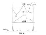
図1Aは、LAの圧力および容積の波形を示しており、これらの波形を組み合わせることで、圧力:容積の関係を「8の字」で表している(図1B)。Figure 1A shows the LA pressure and volume waveforms, which combine to form a "figure of eight" representation of the pressure:volume relationship (Figure 1B).
心房拡張期(心室収縮を介する)のLAの拡張は、リザーバ機能として知られており、図1Aおよび図1Bの(1)と標識付けられたセグメントで表されている。僧帽弁が拡張早期に開くと、LAおよびLVの圧力が等しくなり、血液はLVに受動的に駆出される。これは、導管機能として知られており、図1Aおよび図1Bのセグメント(2)で表されている。次に、拡張期の終わりに、僧帽弁が閉じる直前に、心房が収縮し、図1Aおよび図1Bのセグメント(4)および(5)で表される能動的なポンプ機能を果たす。The expansion of the LA during atrial diastole (via ventricular contraction) is known as the reservoir function and is represented by the segment labeled (1) in Figures 1A and 1B. When the mitral valve opens in early diastole, the pressures in the LA and LV are equalized and blood is passively ejected into the LV. This is known as the conduit function and is represented by segment (2) in Figures 1A and 1B. Then, at the end of diastole, just before the mitral valve closes, the atria contract and perform an active pumping function represented by segments (4) and (5) in Figures 1A and 1B.
うっ血性心不全(CHF)の存在下では、LAの拡張および容積の増加がスティッフネスの増加および高い圧力と結びつくため、図1Bに示されている通常の「8の字」が右上に移動する。スティッフネスの増加により、曲線の形状も変化し、リザーバストレイン(充満時の拡張の減少)およびポンプのストレイン(心房収縮期の圧縮)が低下する。In the presence of congestive heart failure (CHF), the normal "figure of eight" shown in Figure 1B shifts to the upper right as increased LA dilation and volume combine with increased stiffness and higher pressures. Increased stiffness also changes the shape of the curve, decreasing reservoir strain (reduced dilation during filling) and pump strain (compression during atrial systole).
HFpEFは、最初はLV拡張期の充満圧の上昇およびLAを十分に駆出できないことに関連しているが、結果として流体がうっ滞してしばしば肺うっ血を引き起こし、肺高血圧症、RV-to-PC(右心室-肺循環)のアンカップリング、および右心室の過負荷または機能不全になり得る。その結果、左心不全から始まったものはしばしば右心不全へと進行し得る。右心への影響は、肺血管抵抗(PVR)、肺動脈(PA)収縮期圧(これはRV収縮期圧に相当する)の上昇、RVの仕事量および非効率性の増加、ならびに心拍出量の減少として観察されることがある。LA圧の上昇は、肺動脈楔入圧の上昇およびPVRの増加につながる。この結果、PA収縮期圧が上昇し、圧力差が小さくなるため、PA拡張期の間は心拍出量が減少する。PA収縮期圧の上昇は、収縮期のRVの仕事量を増加させ、時間の経過とともに効率を低下させることにつながる。HFpEF is initially associated with elevated LV diastolic filling pressures and inability to adequately eject the LA, but the resulting fluid retention often leads to pulmonary congestion, which can lead to pulmonary hypertension, RV-to-PC uncoupling, and right ventricular overload or failure. As a result, what begins as left heart failure can often progress to right heart failure. Effects on the right heart can be observed as elevated pulmonary vascular resistance (PVR), pulmonary artery (PA) systolic pressure (which corresponds to RV systolic pressure), increased RV work and inefficiency, and reduced cardiac output. Elevated LA pressure leads to elevated pulmonary artery wedge pressure and increased PVR. This results in elevated PA systolic pressure and reduced cardiac output during PA diastole due to a smaller pressure differential. Elevated PA systolic pressure leads to increased RV work during systole and reduced efficiency over time.
HFpEFの症状を悪化させるLA圧の上昇の役割に対応して、LAから右心房(RA)に血液をシャントしてLA圧およびPCWPを低下させることを試みる心房内装置を提供することができる。初期の臨床研究では有望な結果が示されているが、LAのシャントは肺のうっ血を完全に解消するものではなく、心臓の右側の負担を軽減するのに役立つものでもない。むしろ、ここではRAは左側からの血液のシャントにより増加した容積に対処しなければならない。さらに、LAの圧力を低下させるだけでは、根本的な心房スティッフネスに対処せず、心周期のすべての段階でLAの機能を完全に回復させるのに役立たない。例えば、心房収縮の活性段階にLA圧を低下させてもLAとLVとの間の圧力差は大きくならない。その結果、LVの拡張終期の充満は最適化されず、むしろ、右側へと容積がシャントされているため、心拍出量は低下しやすくなる。さらに、LAシャントは、HFpEF患者に共通の状態である心房細動(AF)に苦しむ患者には効果的でないことがある。In response to the role of elevated LA pressure in exacerbating the symptoms of HFpEF, intra-atrial devices can be provided that attempt to shunt blood from the LA to the right atrium (RA) to reduce LA pressure and PCWP. Although early clinical studies have shown promising results, LA shunting does not completely resolve pulmonary congestion or help relieve the strain on the right side of the heart. Instead, the RA must now address the increased volume caused by shunting of blood from the left side. Furthermore, simply lowering LA pressure does not address the underlying atrial stiffness and does not help fully restore LA function during all phases of the cardiac cycle. For example, lowering LA pressure during the active phase of atrial contraction does not increase the pressure differential between the LA and LV. As a result, LV end-diastolic filling is not optimized, and instead cardiac output is prone to decline due to volume shunting to the right side. Furthermore, LA shunts may not be effective in patients suffering from atrial fibrillation (AF), a condition common in patients with HFpEF.
本開示のいくつかの態様では、加圧要素および制御回路を備えた心房機能不全を治療するシステムが開示される。加圧要素は、患者の心臓の左心房内に位置決めされるように構成され得る。制御回路は、左心房の相対容積を増加させて左心房内の充満圧を低下させることにより、心房拡張期に左心房の圧力を低下させて、患者の肺から酸素化された血液を引き出すように加圧要素を操作し、左心房の相対容積を減少させて心房収縮期の左心房圧を上昇させることにより、心房収縮期に左心房の圧力を上昇させるように加圧要素を操作するように構成され得る。心房収縮期の左心房圧の上昇によって、左心房と左心室との間の圧力差を増加させ、左心室の拡張期充満を改善する。In some aspects of the present disclosure, a system for treating atrial dysfunction is disclosed that includes a pressurizing element and a control circuit. The pressurizing element may be configured to be positioned within the left atrium of the patient's heart. The control circuit may be configured to operate the pressurizing element to decrease the left atrial pressure during atrial diastole by increasing the relative volume of the left atrium to decrease filling pressure in the left atrium, thereby drawing oxygenated blood from the patient's lungs, and to increase the left atrial pressure during atrial systole by decreasing the relative volume of the left atrium to increase the left atrial pressure during atrial systole. The increase in the left atrial pressure during atrial systole increases the pressure difference between the left atrium and the left ventricle, improving diastolic filling of the left ventricle.
いくつかの態様では、システムは、加圧要素に結合され、左心房に加圧要素を位置決めするように構成されている心房位置決め構造をさらに備えることができる。心房位置決め構造は、中隔アンカーまたは左心耳アンカーを備えることができる。心房位置決め構造が、患者の心臓の右心房と左心房との間に経中隔的に延びるように構成されたシャフトを備えることができる。シャフトは、左心房における加圧要素の位置決めを容易にするために、曲がりまたはカーブを有して予備成形され得る。いくつかの態様では、システムは、左心房における加圧要素の位置決めを容易にするために、シャフトを通って送達されるように構成された成形スタイレットをさらに備えることができる。In some aspects, the system may further comprise an atrial positioning structure coupled to the pressurizing element and configured to position the pressurizing element in the left atrium. The atrial positioning structure may comprise a septal anchor or a left atrial appendage anchor. The atrial positioning structure may comprise a shaft configured to extend transseptally between the right and left atria of the patient's heart. The shaft may be preformed with a bend or curve to facilitate positioning of the pressurizing element in the left atrium. In some aspects, the system may further comprise a shaped stylet configured to be delivered through the shaft to facilitate positioning of the pressurizing element in the left atrium.
いくつかの態様では、加圧要素がバルーンを構成し得る。左心房の圧力を上昇させるように加圧要素を操作することは、バルーンを液体または気体で満たすことを含むことができ、左心房の圧力を低下させるように加圧要素を操作することは、バルーンから液体または気体を除去することを含むことができる。バルーンの遠位端部は、バルーンの遠位端部が非外傷性であるように、バルーン内へと凹んでいることができる。バルーンが、開口した中央ルーメンを備えることができる。いくつかの態様では、システムは、圧力チャンバと、バルーンと圧力チャンバとの間に配置された少なくとも1つのポンプとを備えた加圧構成部品をさらに備えることができる。加圧構成部品が、固定型外部構成部品、歩行仕様外部構成部品、または植込型構成部品であるように構成され得る。In some aspects, the pressurizing element may comprise a balloon. Operating the pressurizing element to increase the left atrial pressure may include filling the balloon with a liquid or gas, and operating the pressurizing element to decrease the left atrial pressure may include removing the liquid or gas from the balloon. A distal end of the balloon may be recessed into the balloon such that the distal end of the balloon is atraumatic. The balloon may comprise an open central lumen. In some aspects, the system may further comprise a pressurizing component comprising a pressure chamber and at least one pump disposed between the balloon and the pressure chamber. The pressurizing component may be configured to be a fixed external component, an ambulatory external component, or an implantable component.
いくつかの態様では、心房位置決め構造は、中隔アンカーを備えることができる。中隔アンカーが、患者の心臓の心房中隔の左側および右側に対してそれぞれ拡張するように構成された第1および第2の拡張可能部材を備えることができ、加圧要素が第1の拡張可能部材に取り付けられ得る。In some aspects, the atrial positioning structure can include a septal anchor. The septal anchor can include first and second expandable members configured to expand, respectively, against the left and right sides of the atrial septum of the patient's heart, and the pressurizing element can be attached to the first expandable member.
いくつかの態様では、左心房に位置決めされるように構成された加圧要素は、第1の加圧要素であることができる。システムは、患者の肺動脈内に位置決めされるように構成され得る第2の加圧要素をさらに備えることができる。第2の加圧要素は、肺動脈位置決め構造に結合され得、肺動脈位置決め構造は、患者の肺動脈に第2の加圧要素を位置決めするように構成され得る。制御回路は、第1の加圧要素および第2の加圧要素を操作して、左心房および肺動脈に協調された圧力変更を引き起こすようにさらに構成され得る。第1の加圧要素が第1のバルーンを構成でき、第2の加圧要素が第2のバルーンを構成できる。In some aspects, the pressurizing element configured to be positioned in the left atrium can be a first pressurizing element. The system can further include a second pressurizing element that can be configured to be positioned in the patient's pulmonary artery. The second pressurizing element can be coupled to a pulmonary artery positioning structure, which can be configured to position the second pressurizing element in the patient's pulmonary artery. The control circuitry can further be configured to operate the first pressurizing element and the second pressurizing element to cause coordinated pressure changes in the left atrium and the pulmonary artery. The first pressurizing element can comprise a first balloon, and the second pressurizing element can comprise a second balloon.
いくつかの態様では、心房機能不全を治療する方法が開示される。本方法は、患者の左心房内に加圧要素を送達することと、左心房の相対容積を増加させて左心房内の充満圧を低下させることにより、心房拡張期に左心房の圧力を低下させて、患者の肺から酸素化された血液を引き出すように加圧要素を操作することと、左心房の相対容積を減少させて心房収縮期の左心房圧を上昇させることにより、心房収縮期に左心房の圧力を上昇させるように加圧要素を操作することとを含むことができ、心房収縮期の左心房圧の上昇によって、左心房と左心室との間の圧力差を増加させ、左心室の拡張期充満を改善する。In some aspects, a method of treating atrial dysfunction is disclosed. The method may include delivering a pressurizing element into the patient's left atrium, manipulating the pressurizing element to increase the relative volume of the left atrium to decrease filling pressure in the left atrium, thereby decreasing left atrial pressure during atrial diastole to draw oxygenated blood from the patient's lungs, and manipulating the pressurizing element to increase the left atrial pressure during atrial systole, by decreasing the relative volume of the left atrium to increase left atrial pressure during atrial systole, where the increased left atrial pressure during atrial systole increases the pressure differential between the left atrium and the left ventricle and improves diastolic filling of the left ventricle.
前述の段落の方法は以下の特徴のうちの1つまたは複数をさらに有することができる。加圧要素はバルーンであり得る。本方法は、制御回路にて、患者に通信可能に結合されたセンサから患者の心臓の心周期に対応する信号を受信することと、信号の一部に応答して、左心房の圧力を低下させるように加圧要素を操作することと、信号の追加の部分に応答して、左心房の圧力を上昇させるように加圧要素を操作することとをさらに含むことができる。センサは電気センサまたは圧力センサを構成することができる。本方法は、左心房内に加圧要素を固定することをさらに含むことができる。左心房内に送達される加圧要素は、第1の加圧要素であることができ、本方法は、患者の肺動脈に第2の加圧要素を送達することと、肺動脈収縮期に肺動脈内の圧力を低下させて、肺動脈の収縮期圧を低下させ、患者の心臓の右心室の仕事量を減少させるように第2の加圧要素を操作することと、肺動脈弁が閉じた後の肺動脈拡張期に肺動脈内の圧力を上昇させて、肺動脈拡張期圧を上昇させ、肺血管抵抗に打ち勝って心拍出量を増加させるように、第2の加圧要素を操作することとをさらに含むことができる。The method of the preceding paragraph may further include one or more of the following features: The pressurizing element may be a balloon. The method may further include receiving, in the control circuit, a signal corresponding to a cardiac cycle of the patient's heart from a sensor communicatively coupled to the patient, and operating the pressurizing element in response to a portion of the signal to reduce pressure in the left atrium, and operating the pressurizing element in response to an additional portion of the signal to increase pressure in the left atrium. The sensor may comprise an electrical sensor or a pressure sensor. The method may further include securing the pressurizing element within the left atrium. The pressurizing element delivered into the left atrium can be a first pressurizing element, and the method can further include delivering a second pressurizing element to the patient's pulmonary artery, operating the second pressurizing element to reduce pressure in the pulmonary artery during pulmonary artery systole to reduce pulmonary artery systolic pressure and reduce right ventricular work of the patient's heart, and operating the second pressurizing element to increase pressure in the pulmonary artery during pulmonary artery diastole after the pulmonary valve closes to increase pulmonary artery diastolic pressure and overcome pulmonary vascular resistance to increase cardiac output.
本開示の特定の態様によると、システムは、心周期の様々な部分の間、左心房の動作を支えるように操作され得る植込型流体変位要素(例えば、バルーン、タービン、ポンプまたは他の加圧要素)を備える。加圧要素は、患者の心臓の左心房内に経皮的に位置決めされ、固定され得る。植込型加圧要素は、種々のプログラム可能なタイミングスキームを用いて容積変位および圧力調整を通じて心臓の機能性を補助するように操作可能である。According to certain aspects of the present disclosure, the system includes an implantable fluid displacement element (e.g., a balloon, turbine, pump, or other pressurizing element) that can be operated to support left atrium operation during various portions of the cardiac cycle. The pressurizing element can be percutaneously positioned and secured within the left atrium of the patient's heart. The implantable pressurizing element is operable to support cardiac functionality through volume displacement and pressure regulation using a variety of programmable timing schemes.
本開示の特定の態様によると、システムは、心周期の様々な部分の間、(例えば、圧力および真空を生じさせることによって)前方流および/または逆流を引き起こすように協調して操作され得る2つの植込型流体変位要素(例えば、バルーン、タービン、ポンプまたは他の加圧要素)を備える。2つの加圧要素は、患者の心臓および/または脈管構造内の2つの別個の位置に経皮的に位置決めされ、固定され得る。2つの植込型加圧要素は、同時のタイミングで(例えば、バルーンの場合、両方が拡張される、両方が収縮される)、真逆のタイミングで(例えば、バルーンの場合、一方が拡張されて他方が収縮される、または軸流ポンプの場合、一方は前方へ、他方は後方へ)、または種々のプログラム可能なタイミングスキームを用いて容積変位および圧力調整を通じて心臓の機能性を補助するために、2つの異なる要素間の先行する、もしくは遅れたタイミングで非同時に、一緒にまたは独立して機能するように操作可能および/またはプログラム可能である。According to certain aspects of the present disclosure, the system comprises two implantable fluid displacement elements (e.g., balloons, turbines, pumps or other pressurizing elements) that can be operated in concert to induce forward and/or reverse flow (e.g., by generating pressure and vacuum) during various portions of the cardiac cycle. The two pressurizing elements can be percutaneously positioned and secured at two separate locations within the patient's heart and/or vasculature. The two implantable pressurizing elements can be operated and/or programmed to function together or independently, non-simultaneously, with simultaneous timing (e.g., in the case of balloons, both are expanded and both are deflated), with opposite timing (e.g., in the case of balloons, one is expanded and the other is deflated, or in the case of axial pumps, one forward and the other backward), or with leading or lagging timing between the two different elements to aid cardiac functionality through volumetric displacement and pressure regulation using various programmable timing schemes.
以下に記述する発明を実施するための形態は、主題技術の様々な構成を説明するものであって、主題技術が実施され得る唯一の構成を示すことを意図したものではない。発明を実施するための形態は、主題技術の完全な理解をもたらすために具体的な詳細を含む。したがって、特定の態様に関して、非限定的例として寸法が提供されてもよい。しかし、当業者であれば、これらの具体的な詳細がなくても主題技術を実施できることは明らかであろう。場合によっては、周知の構造および構成部品は、主題技術の概念を不明瞭にすることを回避するためにブロック図形式で示されている。The detailed description of the invention described below describes various configurations of the subject technology and is not intended to represent the only configurations in which the subject technology may be practiced. The detailed description of the invention includes specific details to provide a thorough understanding of the subject technology. Thus, dimensions may be provided as non-limiting examples for certain aspects. However, it will be apparent to one of ordinary skill in the art that the subject technology can be practiced without these specific details. In some cases, well-known structures and components are shown in block diagram form to avoid obscuring the concepts of the subject technology.
本開示は、主題技術の実施例を含み、添付の特許請求の範囲を限定するものではないことを理解されたい。ここで、主題技術の様々な態様が、特定の、しかし非限定的な実施例に従って開示される。本開示に記載される様々な実施形態は、異なる方法および変形で、所望の用途または実施態様に応じて実行することができる。It should be understood that the present disclosure includes examples of the subject technology and is not intended to limit the scope of the appended claims. Various aspects of the subject technology are disclosed herein according to specific, but non-limiting examples. The various embodiments described in the present disclosure can be implemented in different ways and with modifications depending on the desired application or implementation.
以下の発明を実施するための形態では、本開示の完全な理解をもたらすために、多数の具体的な詳細が示されている。しかしながら、当業者には本開示の実施形態が一部の具体的詳細なしで実施できることが明らかになるであろう。他の場合には、本開示を不明瞭にしないために、周知の構造および技術は詳細に示されていない。In the following detailed description, numerous specific details are set forth to provide a thorough understanding of the present disclosure. However, it will be apparent to one skilled in the art that embodiments of the present disclosure may be practiced without some of the specific details. In other instances, well-known structures and techniques have not been shown in detail in order not to obscure the present disclosure.
本開示の態様は、心不全および/または心房細動を含む心房機能不全のためのシステムおよび方法に関する。システム100、600などのシステムの使用をHF用途について以下に記述するが、システムは、LAの本来の機能および拍動を回復させる能力に基づいて、非HFのAF患者の治療にも適していることを理解すべきである。今日、多くの場合メイズ手術と呼ばれるアブレーション手術を介してAFを治療することが一般的であり、それより、医師は、細動をなくすために、小切開、ラジオ波、凍結、マイクロ波または超音波エネルギーを用いて、LA内の電気回路を破壊する瘢痕組織を形成する。これは、手術でも効果があるが、現在使用されているインターベンション技術を用いた場合はそれほど効果的ではない。アブレーションが不十分だと持続性AFにつながる可能性があるが、アブレーションが過剰だとLAの壁を硬くする瘢痕化を引き起こし得、最終的にはHFにつながり得る。対照的に、後述のLAバルーン102を用いてLAの機能(拡張および収縮)を回復させることにより、電気的変動があっても、また過剰な瘢痕化を引き起こし得るアブレーションを必要とせずに、AFの症状を解消することができる。Aspects of the present disclosure relate to systems and methods for heart failure and/or atrial dysfunction, including atrial fibrillation. While the use of systems such as
左心房心臓補助システム
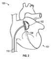
図2は、植込型加圧要素が患者に植え込まれた例示的システム100を示す。図2の実施例では、システム100は、例示のためにバルーンとして実装された加圧要素102を備える。図示されているように、心房位置決め構造106は、加圧要素102に結合され、患者の心臓101の左心房LAに加圧要素102を位置決めするように構成されている。図2では見えていないが、システム100は、左心房リザーバストレインの増加および左心房の容積の相対的増加をシミュレートして左心房内の充満圧を低下させることにより、心房拡張期に左心房の圧力を低下させて、患者の肺から酸素化された血液を引き出すように加圧要素102を操作するように構成された制御回路も備える。また、制御回路は、左心房の相対容積を減少させて心房収縮期の左心房圧を上昇させることにより、心房収縮期に左心房の圧力を上昇させて、左心房のアクティブストレインの増加をシミュレートするように加圧要素102を操作する。心房収縮期の左心房圧の上昇は、左心房と左心室との間の圧力差を増加させ、左心室の拡張期充満を改善する。 Left Atrial Cardiac Assist System Figure 2 illustrates an
供給ライン110が示されており、これらを介して、流体または気体が、加圧要素102のバルーン実施態様の拡張または収縮のために供給または除去され得、またはこれらによって、制御信号が加圧要素102の他の実施態様の操作のために提供され得る。供給ライン110は、加圧要素102を左心房LAに送達するために使用される細長いカテーテル本体に組み込まれても、またはその一部であってもよい。例えば、バルーンおよび非バルーンの両方の実施形態において、いくつかの態様では、カテーテルまたはシースが、大腿静脈を介して経皮的アプローチで送達され、下大静脈を通って右心房RAに進み、心房中隔を越えて左心房LAに進んでもよい。加圧要素102は、細長い本体の遠位端部に配置され、LA内で拡張することができる。図2でバルーンの近位に示されている拡張可能な心房位置決め構造106は、LA内でバルーンを固定するのを助けるために、中隔の左側および/または右側で拡張してもよい。いくつかの実施形態では、バルーンを運ぶカテーテル本体は、RAとLAとの間に配置された別個の経中隔シースを介して送達されてもよい。
システム100は、患者の心周期の一部に対応する信号を生成する心電図(ECG)センサおよび/または圧力センサなどの1つまたは複数のセンサも備えてもよい。加圧要素102は、センサからの信号に基づいて、心周期の様々な部分に合わせて、左心房内に圧力変化(例えば、圧力上昇および/または圧力低下)を引き起こすように操作することができる。The
本開示の態様によれば、図2の左心房補助システム100は、潜在的に右側に問題が発生する前に、心臓の左側の潜在的な機能不全に対処するために、かつ/または肺動脈楔入圧(肺うっ血の代わり)の低下および左心室の充満の改善を介して心臓の両側の機能不全を緩和するために提供される。In accordance with aspects of the present disclosure, the left
心臓の右側の負担を増加させ、心拍出量を減少させるという代償を払ってLA圧のみを低下させる装置を用いたHFpEF治療とは対照的に、本明細書に記載のシステム100は、右心房に負担を加えることなく心臓の左側の負担を減少させることによって心臓を補助し、それによって潜在的に、うっ血および肺動脈楔入圧も減少させ、LV拡張期の充満を改善し、これによって心拍出量の正味の増加をもたらすことができる。これは、心臓の左側に流体/容積変位システム(例えば、左心房内の加圧要素102)を配置することによって達成される。加圧要素102がバルーンとして実装されている本明細書に記述される実施例では、バルーンの拡張および収縮は、各患者に対する補助を最適化し、心周期の間、常に血液を適切な方向に移動させ続けるような方法でタイミングがとられる。In contrast to HFpEF treatments using devices that only reduce LA pressure at the expense of increasing the workload of the right side of the heart and decreasing cardiac output, the
心房拡張期に左心房内でバルーン102を収縮させると、LAリザーバストレインの増加(例えば、充満時の容積の増加)をシミュレートして、LAの相対容積を増加させ、充満圧を低下させることによって、肺から酸素化された血液を引き出すことを助けることができる。次に、拡張期周期の活性部分(例えば、心房収縮中)にバルーン102を拡張させることにより、バルーンは、周期の活性段階の間にLAの相対容積を減少させてLA圧を上昇させ、それにより、LA対LVの圧力差を増加させ、左心室の拡張期充満を改善することによって、ポンプ/アクティブストレインの増加をシミュレートすることができる。LAバルーン102のこの操作は、スティフネスおよび壁応力が増加しつつある心臓の領域(例えば、LAおよびLV)のコンプライアンスを回復するのに役立つ。Deflating the
様々な動作シナリオにおいて、バルーン102(または、LAにおける流体/容積変位のための加圧要素の他の実施態様)は、バルーンの配置および各患者の特定のニーズに応じて操作することができる。In various operating scenarios, the balloon 102 (or other implementation of a pressurizing element for fluid/volume displacement in the LA) can be manipulated depending on the placement of the balloon and the specific needs of each patient.
バルーン102の拡張および収縮は、初期(例えば、固定)のタイミングに基づくことができ、または、心電図(例えば、EKGまたはECG)センサ、圧力センサ(例えば、LA内またはその近傍の圧力センサ)、またはそれらの組み合わせからのセンサ信号によってトリガすることができる。Inflation and deflation of the
図3は、ECG信号200のタイミングに対する、LAバルーン102のバルーン拡張および収縮の可能なシーケンスを示す波形202を示す。Figure 3 shows a
図3の波形を生成できるバルーン102のタイミングの例示的な一実施態様では、LAバルーン102は、Rピークの検出時に時間遅延(例えば、Rピーク後100ミリ秒の遅延)を加えて収縮するようにトリガされる。このようにして、システムは、LAバルーンの収縮が、僧帽弁が閉じているときの心室収縮中に生じるLA圧/容積周期の自然な拡張/リザーバ機能段階と一致するように、LAバルーン102の収縮を開始する。LAバルーン102の拡張が、僧帽弁が閉じる直前の心室拡張期の終わりの心房収縮(例えば、a波のピークが発生したときの心房の圧力/容積周期の活発な収縮部分)と一致して、心房と心室の圧力差を高め、心室充満(例えば、左心室拡張末期容積、LVEDV)を増加させるように、LAバルーンの拡張は、ECGのP波ピークまたはRピークに基づき、追加の時間遅延(例えば、Rピーク後600ミリ秒の時間遅延)を加えて開始するようにトリガされてもよい。In one exemplary implementation of the timing of the
図4は、ECG信号のタイミングに対する、2つのLA圧波形300、312を示す。また、この図は、心周期のある時点も示す。例えば、LA収縮302、僧帽弁閉鎖304、LAの弛緩および充満306、LA満杯308、LA駆出310などである。修正されていない波形312は、LAバルーンを使用していない心臓の左心房圧波形を示し、修正された波形300は、LAバルーンを使用している心臓の左心房圧波形を示す。示されているように、修正された波形300のa波ピーク(302に相当)は、バルーンの拡張によりLAが収縮したときに、修正されていない波形312の302よりも高く、この波のブーストは、心不全および/または心房細動に関連する心房機能不全の結果として低下し得る左心房の自然な収縮性を増幅し、左心室の充満を改善して心拍出量を支えるのに役立つ。逆に、Rピーク直後にバルーンを収縮させると、修正されていない波形312と比較して、心房の充満中の圧力が低下し(306に相当)、v波のピークが低くなる(308に相当)。この充満圧の低下により、肺動脈楔入圧が低下し、肺のうっ血が減少するはずである。FIG. 4 shows two
図5~図9は、LAバルーン102および心房位置決め構造106の例示的実施形態を示す。Figures 5-9 show an exemplary embodiment of the
一般に、バルーン102は、その関連する位置決め構造から分離されていても、または位置決め構造に組み込まれていてもよい。いずれの実施態様においても、心周期を通して心臓内でその関連するバルーンの位置を維持する位置決め構造が提供される。図5の例示的斜視図では、LAバルーン102は、心房中隔を通って延びる部分700で経中隔的に位置決めされるように構成された心房位置決め構造106に取り付けられているドーム形の拡張可能な構造である。部分700は、心房位置決め構造とみなしてもよく、心臓内に一時的に配置される上述のカテーテル本体、またはより長期的に心臓内に配置され得るより短い経中隔シャフトを備えてもよい。心房位置決め構造106は、図6により詳細に示される2つのディスク800および802の形態を実質的にとり得る拡張可能なワイヤメッシュ(例えば、自己拡張型、型形状固定(shape-set)ニチノール製ワイヤメッシュ)を含むドーナツ状構造を構成する。システムは、経中隔的に送達されるときに、位置決め構造106およびドーム形の拡張可能構造102の直径を制限できるシース内から展開されてもよい。遠位端部が左心房内に進入したら、バルーン102が取り付けられた遠位ディスクが左心房内で拡張できるように、シースを後退させてもよい(または、バルーンカテーテルおよび位置決め構造をシースに対して前進させてもよい)。次いで、システムを右心房に向かって引き戻し、遠位ディスクの近位面を中隔壁の左心房に面した面に接触させることができる。シースを後退させ続けると、近位ディスクは、近位ディスクの遠位面が中隔壁の右心房に面する面に接触してシステムを中隔に対して固定するように、露出し、拡張する。図5の矢印は、どのようにバルーン102が交互に拡張および収縮され得るかを示す。In general, the
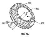
図6は、バルーン102が位置決め構造106のLA側に組み込まれた状態で、心房中隔809の両側に拡張可能部材800および802で固定された、図5の心房位置決め構造106およびLAバルーン102の部分側面断面図を示す。拡張可能部材800および802は、患者の心臓に(部材802については心房中隔を通って)挿入するために折り畳まれ、その後、位置決め構造106を中隔に固定するために拡張され得る。バルーン102は、抗血栓材料を含むことができる。図6の矢印は、中隔809に固定されたバルーン102がどのようにして交互に拡張および収縮できるかを示す。ドーム形のバルーン106が図6および図7に示されているが、LAバルーン102は、バルーン102を通る中央ルーメンを介してLAへの経中隔アクセスを可能にするドーナツ状ループまたは他の形態として成形され得ることを理解すべきである。左心房への導管を提供する中央ルーメンは、初期送達、カテーテルの外部部分のハブからの直接圧力測定、圧力センサ(例えば、光ファイバ圧力センサ)、静脈系へのシャント経路、または左心房へのアクセスが望まれ得る任意の他の目的を容易にするガイドワイヤルーメンとして使用することができる。例えば、図7A~図7Bは、左心房室へのアクセスを維持するための開口した中央ルーメン900を含むマルチルーメンカテーテル902を備えたLAバルーン102の実施態様を示す。カテーテル902は、バルーン102を拡張および収縮させるために使用できる別のルーメン904を備える。図7Aの断面図が図7Bに示される。図示されているように、中央ルーメン900は、両矢印901によって示されるように、左心房室へのアクセスを提供する。さらに、流体ルーメン904は、第2の両矢印903で描かれているように、バルーン102へ、またバルーン102から流体を送達できる。FIG. 6 shows a partial side cross-sectional view of the
いくつかの操作シナリオでは、患者のHFを一時的に治療した後、経中隔LAバルーンおよび心房固定構造は除去でき、経中隔開口部は閉鎖されても、または開いたままであってもよい。図8は、右心房に配置された第1の固定部材800および左心房に配置された第2の固定部材802を有する経中隔アンカーとして実装されたLA位置決め構造106によってLA内に位置決めされたLAバルーン102と、左側の部材802に取り付けられたLAバルーン102とを示す。図9は、LAバルーン102が、左心耳(LAA)に遠位端部で固定される構造106により固定される代替的実装態様を示す。LAAに(例えば、図9に示すような拡張可能ケージを用いて)固定することは、構造106が、LAの全体的な容積を減少させ、塞栓症のリスクおよび/またはAFの影響を最小化するのに役立つように、同時にLAAの一部を閉鎖するように実施することもできる。LA固定構造106は、LAバルーン102をLAに位置決めするために他の場所に固定することができることも理解されるべきである。一実施例では、LA固定構造106は、1つまたは複数の肺静脈のオリフィスに固定するように構成された固定部材であってもよい。さらに、本明細書に記載されている実施形態のいずれかにおいて、また図8~図9に示されているように、供給ライン110は、点線114で図示されている上大静脈(SVC)、または実線110で図示されているように下大静脈(IVC)から、右心房を介してLAにアクセスすることができる。In some operational scenarios, after temporarily treating the patient's HF, the transseptal LA balloon and atrial fixation structure can be removed and the transseptal opening may be closed or left open. FIG. 8 shows the
LAバルーンの別の実施態様を図10A~図10Dに示す。LAバルーン502の遠位端部504は、LAバルーン502内に凹んでいる。陥入している先端により、ガイドワイヤが存在しない場合を含むがこれに限定されず、バルーン502の遠位端部504を非外傷性にすることができる。バルーン502は、図10Dに示すように、上述した同様の固定機構によって心臓に固定することができるが、図10Cに示すように、それを必要としない。図10Cは、LAバルーン502が、心房位置決め構造としてシャフト506を用いてLA内に位置決めされ得ることを示す。一実施態様では、シャフト506は、マルチルーメンポリマーシャフトであってもよい。シャフト506は、送達中の適切な配置および操作中の安定化を容易にするのを助けるように、約60°または様々な異なる角度の曲がりまたはカーブを有して予備成形され得る。シャフト506は、複数のルーメンを構えることができる。例えば、シャフト506は、ガイドワイヤ用の別個のルーメン、バルーン502を拡張および収縮させるための別個のフロールーメン、および光ファイバ圧力センサ用の別個のルーメンを有することができる。また、シャフト506は、カテーテルの遠位先端を安定させ、操作時にバルーンの位置を維持するための補強用スタイレットを収容するルーメンを含んでいてもよい。補強用スタイレットは、遠位先端が所望の位置まで進む前または後に挿入することができる。補強用スタイレットは、シャフト506に所望の曲がりまたはカーブを付与するために、曲がりまたはカーブを有して予備成形されていてもよい。Another embodiment of the LA balloon is shown in Figures 10A-10D. The
様々な実施態様において、LAバルーン102、502は、球形、楕円形、円筒形、平面、ドーム形、ドーナツ状、またはLAを加圧する(例えば、制御可能な方法で圧力を上昇または低下させる)のに適した任意の他の幾何学的構成である形状を有することができる。様々な形状は、患者における配置を改善することができる。他の実施態様では、LAバルーン102、502は、患者の心臓により適した、ならびに/または拡張および/もしくは収縮時に優先的なフローパターンを提供するために、様々なサイズを有することができる。In various embodiments, the
LAバルーン102のようなLAバルーンは、1つまたは複数の他の植込型要素と組み合わせて提供できることをさらに理解すべきである。It should further be appreciated that an LA balloon, such as
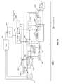
図11は、図2では見えない上述のシステム100に組み込まれてもよく、本明細書に記載されるようにLAバルーン102を操作するように構成された様々な構成部品を示す。図11は、上述した単一のバルーンシステム、またはさらに後述するデュアルバルーンシステムで使用可能であってもよい構成部品を示す。したがって、図11に図示された構成部品のすべてが、単一のバルーンシステムに必要とされるかまたは利用されるとは限らなくてもよい。システム100の構成部品に関するさらなる詳細は、図14および段落[0046]を含むがこれらに限定されない、2019年2月6日に出願された米国仮出願第62/801,819号にも記載されており、その全文が参照により本明細書に組み込まれる。図11の実施例では、システム100は、制御回路(図示せず)、電源(図示せず)、圧力チャンバまたはリザーバ1900、真空チャンバまたはリザーバ1902、およびポンプ1907を備えることができる。図示されているように、ソレノイド1908は、圧力チャンバ1900および真空チャンバ1902を流体ライン(例えば、図2の流体ライン110の実施態様)に流体的に結合する管類に配置されてもよく、マイクロコントローラ1927の制御回路によって制御され、バルーン102の拡張および収縮を制御することができる。一実施形態では、ECGセンサ1903が患者1901に接続され、患者のECG信号はデータ収集ユニット1905に送信され、このデータ収集ユニット1905は、ECG信号のR波に相関する設定閾値を検索するようにソフトウェア1915によってプログラムされている。閾値が検出されると、データ収集ユニット1905は、マイクロコントローラ1927にパルス(例えば、方形波)を送信する。ソフトウェア1915は、データ収集ユニット1905によって送信されたパルスについてマイクロコントローラ1927を監視し、その情報を用いてECG信号のR波の間隔(R-R間隔)を連続的に計算する。LAバルーンの拡張は、計算されたR-R間隔およびパラメータ1919(拡張時間の長さ、ECG特徴1917の検出後のオフセット/遅延時間、および充満量を含む)を使用してタイミングが取られ、これらのパラメータ1919は、ユーザ入力/コントローラ1921を用いて調整され得る。次に、R-R間隔のタイミングおよびユーザ入力1921に基づいて、ソフトウェア1915は、マイクロコントローラ1927と通信してソレノイド1908を作動させ、バルーンのルーメンを、拡張のために圧力チャンバ1900へ、または収縮のために真空チャンバ1902へと、いずれかに開放する。11 illustrates various components that may be incorporated into the
システム100は、固定型の外部システム(例えば、ベッドサイド補助用)として描かれているが、図11および上述の他の図面の構成部品は、歩行使用のために、または患者に植え込むために配置することもできる(例えば、バルーン102の駆動システムは、外部コンソール、ウェアラブルな外付けポータブルユニット内にあることができ、または完全植込型であってもよい)。システム100は、一時的な使用、短期的な使用、中期的な使用、長期的な使用、または永久的な使用のために提供され得る。一時的な場合には、LA位置決め構造106は、外傷がないように患者から取り外されるように構成される。Although
所望であれば、バルーン102は、対応する空洞内の圧力データを収集する圧力センサ/モニタ1923、例えば、光ファイバ圧力センサまたは他の同様の方法を備えることができる。この圧力センサからの圧力データは、バルーンの拡張および/もしくは収縮を駆動もしくはトリガするために使用することができ、ならびに/または、出力ディスプレイ1925を介して、もしくは別個にアップロードされたときに、リアルタイムで患者、医師、もしくは他の人に情報を提供するために収集することができる。いくつかの実施形態では、センサ1923は、様々な目的でバルーン内の圧力を監視するために使用することもできる。If desired, the
本明細書では、LA加圧要素102がバルーンとして実装されている様々な実施例が説明されているが、LA補助システム100は、アクティブポンプ、軸流ポンプ、タービン、または容積および流体を変位させる他の機構など、他の加圧要素を用いて実施されてもよいことを理解すべきである。より一般的には、要素102は、患者の心臓の左側の1つまたは複数の部分と流体連通するように配置するための、生体適合性があり植込可能な加圧(例えば、圧力制御)、流体変位、および/または容積変位機構の任意の適切な組み合わせとして実装することができる。例えば、LA加圧要素102は、操作されると、左心房の容積変位を引き起こすことができる。Although various embodiments are described herein in which the
図12は、主題技術の1つまたは複数の態様が実装され得る電子システムを概念的に示す。電子システムは、例えば、スタンドアロンデバイス、ポータブル電子デバイス、例えば、ラップトップコンピュータ、タブレットコンピュータ、電話、ウェアラブルデバイスもしくはパーソナルデジタルアシスタント(PDA)、または一般に、患者の心臓および/もしくは肺血管系に植え込まれた加圧装置に通信可能に接続できる任意の電子デバイスに実装された左心房補助システムのための制御回路1913であってもよく、またはその一部であってもよい。このような電子システムは、様々な種類のコンピュータ可読媒体と、他の様々な種類のコンピュータ可読媒体用のインタフェースとを備える。電子システムは、バス1008、処理ユニット1012、システムメモリ1004、読み取り専用メモリ(ROM)1010、永久記憶デバイス1002、入力デバイスインタフェース1014、出力デバイスインタフェース1006、およびネットワークインタフェース1016、またはそれらのサブセットおよび変形を備える。12 conceptually illustrates an electronic system in which one or more aspects of the subject technology may be implemented. The electronic system may be, or may be part of, a
バス1008は、電子システムの多数の内部デバイスを通信可能に接続するすべてのシステムバス、周辺バスおよびチップセットバスを総称する。1つまたは複数の実施形態では、バス1008は、処理ユニット1012を、ROM1010、システムメモリ1004および永久記憶デバイス1002と通信可能に接続する。これらの様々なメモリユニットから、処理ユニット1012は、主題開示のプロセスを実行するために、実行する命令および処理するデータを取得する。処理ユニットは、異なる実施形態において、単一のプロセッサまたはマルチコアプロセッサであり得る。
ROM1010は、電子システムの処理ユニット1012および他のモジュールが必要とする静的なデータおよび命令を格納する。一方、永久記憶デバイス1002は、読み書きメモリデバイスである。このデバイスは、電子システムがオフのときでも命令およびデータを格納する不揮発性メモリユニットである。主題開示の1つまたは複数の実施形態は、永久記憶デバイス1002として大容量記憶デバイス(例えば、磁気ディスクまたは光ディスクおよびその対応するディスクドライブ)を使用する。The
他の実施形態は、永久記憶デバイス1002として、取り外し可能な記憶デバイス(例えば、フロッピーディスク、フラッシュドライブ、およびその対応するディスクドライブ)を使用する。永久記憶デバイス1002と同様に、システムメモリ1004は、読み書きメモリデバイスである。しかし、記憶デバイス1002とは異なり、システムメモリ1004は、ランダムアクセスメモリのような揮発性の読み書き可能なメモリである。システムメモリ1004は、処理ユニット1012が実行時に必要とする命令およびデータのいずれかを格納する。1つまたは複数の実施形態では、主題開示の処理は、システムメモリ1004、永久記憶デバイス1002、および/またはROM1010に格納される。これらの様々なメモリユニットから、処理ユニット1012は、1つまたは複数の実施形態のプロセスを実行するために、実行する命令および処理するデータを取得する。Other embodiments use a removable storage device (e.g., a floppy disk, a flash drive, and its corresponding disk drive) as the
バス1008は、入力デバイスインタフェース1014および出力デバイスインタフェース1006にも接続する。入力デバイスインタフェース1014によって、ユーザが情報および選択コマンドを電子システムに伝達すること、ならびに/またはセンサがセンサデータをプロセッサ1012に伝達することを可能にする。入力デバイスインタフェース1014と共に使用される入力デバイスとしては、例えば、英数字キーボード、ポインティングデバイス(「カーソル制御デバイス」とも呼ばれる)、カメラもしくは他のイメージングセンサ、心電センサ、圧力センサ、または一般に入力を受信できる任意のデバイスが挙げられる。出力デバイスインタフェース1006は、例えば、電子システムによって生成された画像の表示を可能にする。出力デバイスインタフェース1006と共に使用される出力デバイスとしては、例えば、プリンタ、および表示デバイス、例えば、液晶ディスプレイ(LCD)、発光ダイオード(LED)ディスプレイ、有機発光ダイオード(OLED)ディスプレイ、フレキシブルディスプレイ、フラットパネルディスプレイ、ソリッドステートディスプレイ、プロジェクタ、または情報を出力する他の任意のデバイスが挙げられる。1つまたは複数の実施形態は、タッチスクリーンなど、入力デバイスおよび出力デバイスの両方として機能するデバイスを含んでいてもよい。これらの実施形態では、ユーザに提供されるフィードバックは、任意の形態の感覚フィードバック、例えば、視覚フィードバック、聴覚フィードバック、または触覚フィードバックであってもよく、ユーザからの入力は、聴覚、音声、または触覚入力を含む任意の形態で受信され得る。出力デバイスインタフェース1006は、本明細書に記載されているように、加圧構成部品を操作する(例えば、加圧要素102を制御する)制御コマンドを出力するためにも使用することができる。The
最後に、図12に示すように、バス1008は、ネットワークインタフェース1016を介して電子システムをネットワーク(図示せず)にも接続する。このようにして、コンピュータは、コンピュータのネットワーク(例えば、ローカルエリアネットワーク(「LAN」)、ワイドエリアネットワーク(「WAN」)、もしくはイントラネットなどのネットワーク、またはインターネットのようなネットワークのネットワーク)の一部であってもよい。電子システムの任意のまたはすべてのコンポーネントは、主題開示と組み合わせて使用することができる。Finally, as shown in FIG. 12, the
デュアル心臓補助システム
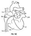
図13A~図13Bは、2つの植込型加圧要素が患者に植え込まれた別の例示的システム600を示す。図13A~図13Bの実施例では、システム600は、例示のためにバルーンとして実装された第1の加圧要素102を備える。図示されているように、心房位置決め構造106は、第1の加圧要素102に結合され、患者の心臓101の左心房LAに第1の加圧要素102を位置決めするように構成されている。上述した心房位置決め構造のいずれも、本明細書に記載のシステム600で利用することができる。図示されているように、システム600は、第2の加圧要素104と、第2の加圧要素104に結合され、患者の肺動脈PA内に第2の加圧要素104を位置決めするように構成された肺動脈位置決め構造108とをさらに備える。図13A~図13Bでは見えないが、システム600は、第1の加圧要素102および第2の加圧要素104を操作して、左心房および肺動脈に協調された圧力変更および/または容積変位を引き起こすように構成された制御回路をさらに備える。供給ライン110および112が示されており、これらを介して、流体または気体が、加圧要素102および104のバルーン実施態様の拡張または収縮のために供給または除去され得、またはこれらによって、制御信号が加圧要素102および104の他の実施態様の操作のために提供され得る。上述したように、供給ライン110は、加圧要素102を左心房LAに送達するために使用される細長いカテーテル本体に組み込まれても、またはその一部であってもよい。供給ライン112は、加圧要素104および肺動脈位置決め構造108を心臓の右側へと送達するために使用される細長いカテーテルに組み込まれても、またはその一部であってもよい。例えば、バルーンおよび非バルーンの両方の実施形態において、いくつかの態様では、カテーテルまたはシースが、大腿静脈を介して経皮的アプローチで送達され、下大静脈を通って、右心房RA、右心室RV、それから肺動脈PA内へと進められてもよい。加圧要素104は、細長い本体の遠位端部またはその付近に配置され、PA内で拡張することができる。図13Aおよび図13Bでバルーンの遠位に示されている拡張可能な肺動脈位置決め構造108は、PA内でバルーンを固定するのを助けるために、肺動脈(または他の場所)で拡張してもよい。いくつかの実施形態では、肺動脈位置決め構造108は、PAの分岐部で固定されてもよい拡張可能なケージを備える。 Dual Cardiac Assist System Figures 13A-13B show another
システム600は、患者の心周期の一部に対応する信号を生成する心電図(ECG)センサおよび/または圧力センサなどの1つまたは複数のセンサも備えてもよい。加圧要素102および104は、センサからの信号に基づいて、心周期の様々な部分に合わせて、左心房および肺動脈にそれぞれ協調された圧力変化(例えば、圧力上昇および/または圧力低下)を引き起こすように操作することができる。
本開示の態様によれば、図13A~図13Bの両側システム600は、心臓の両側の潜在的な機能不全に対処するために提供される。心臓の右側の負担を増加させ、心拍出量を減少させるという代償を払ってLA圧のみを単に低下させる装置を用いたHFpEF治療とは対照的に、本明細書に記載のシステム600は、肺の両側への負担をなくすことによって心臓を補助し、それによって、うっ血および肺動脈楔入圧を減少させ、LV拡張期の充満を改善し、心拍出量を支える。これは、心臓の左側に流体/容積変位システム(例えば、左心房内の加圧要素102)を1つ配置し、心臓の右側に流体/容積変位システム(例えば、肺動脈内の加圧要素104)をもう1つ配置することによって達成される。加圧要素102および加圧要素104がバルーンとして実装されている本明細書に記述される実施例では、バルーンの協調された拡張(図13A参照)および収縮(図13B参照)は、各患者に対する補助を最適化し、心周期の間、常に血液を適切な方向に移動させ続けるような方法でタイミングがとられる。図13Aは、バルーン102、104が拡張したときを示し、図13Bは、バルーン102、104が収縮したときを示す。According to aspects of the present disclosure, the
右側では、バルーンの収縮は、図13Bに示すように、右心室に必要な後負荷および仕事を減少させ、拡張中の肺の充満効率を改善する役割を果たすことができる。例えば、PA収縮期にPAバルーン104を能動的に収縮させると、PA収縮期圧およびRVの作業負荷が低下する。次に、肺動脈弁が閉じた後のPA拡張期に、図13Aに示すようにPAバルーン104を拡張させることにより、PA拡張期圧が上昇し、肺血管抵抗に打ち勝ってより大きな心拍出量がもたらされるようにする。左側では、心房拡張期に左心房内でバルーン102を収縮させると、LAリザーバストレインの増加(例えば、充満時の容積の増加)をシミュレートして、LAの相対容積を増加させ、充満圧を低下させることによって、肺から酸素化された血液を引き出すことを助けることができる。次に、拡張期周期の活性部分の間(例えば、心房収縮中)にバルーン102を拡張させることにより、バルーンは、周期の活性段階の間にLAの相対容積を減少させ、LA圧を上昇させ、それにより、LA対LVの圧力差を増加させ、左心室の拡張期充満を改善することによって、LAポンプ/アクティブストレインの増加をシミュレートすることができる。LAバルーン102およびPAバルーン104のこの協調された動作は、スティッフネスおよび壁応力が増加しつつある心臓の領域(例えば、LAおよびPA)のコンプライアンスを回復するのに役立つ。On the right side, deflating the balloon can serve to reduce the afterload and work required by the right ventricle, improving lung filling efficiency during diastole, as shown in FIG. 13B. For example, actively deflating the
様々な操作シナリオにおいて、バルーン102および104(または、LAおよびPAにおける流体/容積変位のための加圧要素の他の実施態様)は、バルーンの配置および各患者の特定のニーズに応じて独立して、または協調して(例えば、直接同期して、真逆の機能を以て、または心周期を通して拡張および収縮を異なる遅延タイミングを用いた重複するシーケンスで)操作することができる。In various operation scenarios, balloons 102 and 104 (or other implementations of pressurizing elements for fluid/volume displacement in the LA and PA) can be operated independently or in coordination (e.g., directly synchronized, in opposing functions, or in overlapping sequences with different delay timing of expansion and contraction throughout the cardiac cycle) depending on the placement of the balloons and the specific needs of each patient.
バルーン102および104の拡張および収縮は、初期(例えば、固定)のタイミングに基づくことができ、または、心電図(例えば、EKGまたはECG)センサ、圧力センサ(例えば、LA内もしくはその近傍の圧力センサ、およびPA内またはその近傍の圧力センサ)、またはそれらの組み合わせからのセンサ信号によってトリガすることができる。The inflation and deflation of
上述したように、図3は、ECG信号200のタイミングに対する、LAバルーン102のバルーン拡張および収縮の可能なシーケンスを示す波形202を示す。図3は、PAバルーン104のバルーン拡張および収縮の可能なシーケンスを示す波形204も示す。As discussed above, FIG. 3 shows a
ECG信号のRピークの検出
図3の波形を生成できるバルーン102および104のタイミングの例示的な一実施態様では、PAバルーン104は、収縮および拡張がそれぞれ、肺動脈弁の開閉と、収縮期および拡張期の開始に一致するように、ECG信号のRピークの検出時に収縮し、ECG信号のTピークの検出時(またはT波と一致するRピークからずらされた特定のタイミング)に拡張するようにトリガされる。本実施例では、LAバルーン102は、Rピークの検出時に時間遅延(例えば、Rピーク後100ミリ秒の遅延)を加えて収縮するようにトリガされる。このようにして、システムは、LAバルーン102の収縮が、僧帽弁が閉じているときの心室収縮中に生じるLA圧/容積周期の自然な拡張/リザーバ機能段階と一致するように、PAバルーン104の収縮を開始した直後にLAバルーン102の収縮を開始する。LAバルーン102の拡張が、僧帽弁が閉じる直前の心室拡張期の終わりで、心房収縮期(例えば、a波のピークが発生したときの心房の圧力/容積周期の活発な収縮部分)と一致して、心房と心室の圧力差を高め、心室充満(例えば、左心室拡張末期容積、LVEDV)を増加させるように、LAバルーン102の拡張は、ECGのP波ピークまたはRピークの検出に基づき、追加の時間遅延(例えば、Rピーク後600ミリ秒の時間遅延)を加えて開始するようにトリガされてもよい。 Detection of the R-peak of the ECG signal In one exemplary implementation of the timing of the
その全文が本明細書に参考として組み込まれる、2019年2月6日出願の米国仮出願番号第62/801,917号の図7は、ECG信号1604のタイミングに対して、2つの心周期にわたる大動脈圧、PA圧、心房圧、および心室圧を示す一連の波形を示す。さらに、LAバルーン102のバルーン拡張および収縮の可能なシーケンスを例示する波形1600、およびPAバルーン104のバルーン拡張および収縮の可能なシーケンスを例示する波形1602も示されている。さらに、波形1600および1602のバルーン拡張の結果としてのLAおよびPA圧力波への影響は、増強されたLA圧力波形1606および増強されたPA圧力波形1608に図示されている。7 of U.S. Provisional Application No. 62/801,917, filed February 6, 2019, which is incorporated herein by reference in its entirety, shows a series of waveforms illustrating aortic, PA, atrial, and ventricular pressures over two cardiac cycles relative to the timing of an ECG signal 1604. Also shown is waveform 1600 illustrating a possible sequence of balloon inflation and deflation of the
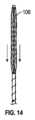
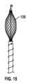
図14~図17に示されるように、PAバルーン104について、PA位置決め構造108は、バルーン104の遠位にあることができ、図14に示す(例えば、血管系を通ってPAに通過する)細長い構成から、図15に示す中間的な拡張構成を経て、図16に示す完全に拡張された構成(例えば、結合されたトルクシャフトを反時計回りに回転させると、内部ねじに沿って遠位部から近位部を延ばし、固定構造を圧縮することができ、一方、トルクシャフトを時計回りに回転させると、固定構造の遠位端部および近位端部を接近させ、その直径を拡大することができる)へと拡張した後に、PAの壁に対して固定する拡張可能なケージとして実装することができる。また、図16は、拡張された構成のPAバルーン104を示す。さらに図14~図16に示されているのは、バルーンカテーテルおよび固定システムをガイドワイヤ上の所定の位置に追跡することができるように、バルーンカテーテルおよび固定システムが導入される前に、解剖学的構造(この場合はPA)内の所望の位置に独立して挿入および前進され得るガイドワイヤ120である。その後、治療過程の間にガイドワイヤは取り外れても、または所定の位置に置かれたままでもよい。14-17, for the
図14~図17は、PAバルーン104に対して遠位に配置されたPA位置決め構造108を示しているが、PA位置決め構造108は、PAバルーン104の近位に配置されても、またはバルーンと一直線に(例えば、バルーンの周りのケージとして)組み込まれてもよいことを理解すべきである。図16に示されるように、PA位置決め構造108は、そこを通る血流を可能にする。Although FIGS. 14-17 show the
図17は、PAの上部に拡張されるケージとして実装されたPA位置決め構造108によってPA内に位置決めされたPAバルーン104を示す。図17に示すように、供給ライン112は、実線112で示されるように、SVCまたはIVCから、右心房および右心室を経由してPAにアクセスすることができる。Figure 17 shows a
様々な実施態様において、LAバルーン102およびPAバルーン104は、同じ形状または異なる形状を有することができ、バルーンの形状は、球形、楕円形、円筒形、平面、ドーム形、ドーナツ状、またはLAおよび/もしくはPAを加圧する(例えば、制御可能な方法で圧力を上昇または低下させる)のに適した任意の他の幾何学的構成である。In various embodiments, the
LA加圧要素102およびPA加圧要素104を有するシステム100を用いたHFpEF治療が本明細書に記載されているが、図2に関連して説明される心周期の特徴に応じて両側の問題に対処するHFpEFおよび/またはAFの治療のための他のシステムが本明細書で企図されている。別の実施例として、図18は、前方流ブーストを強化するためにらせん状に成形されたバルーン1702Aを示す。バルーン1702Aは、上述のようにPA内に位置決めするように構成されてもよい。他の実施形態では、PAにおいて本明細書に記載のバルーンまたは加圧要素のいずれかが、右心室RVにおける位置決めのために構成されてもよい。Although HFpEF treatment with a
図11は、図13A~図13Bでは見えない上述のシステム600に組み込まれてもよく、本明細書に記載されるようにLAバルーン102およびPAバルーン104を操作するように構成された様々な構成部品を示す。システム100の構成部品に関するさらなる詳細は、図21および段落[0057]を含むがこれらに限定されない、2019年2月6日に出願された米国仮出願第62/801,917号にも記載されており、その全文が参照により本明細書に組み込まれる。図11の実施例では、システム600は、制御回路(図示せず)、電源(図示せず)、圧力チャンバまたはリザーバ1900、真空チャンバまたはリザーバ1902、およびポンプ1907を備えることができる。図示されているように、ソレノイド1908、1909は、圧力チャンバ1900および真空チャンバ1902を流体ライン(例えば、図13A~図13Bの流体ライン110および112の実施態様)に流体的に結合する管類に配置されてもよく、マイクロコントローラ1927の制御回路によって制御され、バルーン102および104の拡張および収縮を制御することができる。一実施形態では、ECGセンサ1903が患者1901に接続され、患者のECG信号はデータ収集ユニット1905(Power Lab)に送信され、このデータ収集ユニット1905は、ECG信号のR波に相関する設定閾値を検索するようにプログラムされている。閾値が検出されると、データ収集ユニット1905は、マイクロコントローラ1927にパルス(方形波)を送信する。ソフトウェア1915は、データ収集ユニット1905によって送信されたパルスについてマイクロコントローラ1927を監視し、その情報を用いてECG信号のR波の間隔(R-R間隔)を連続的に計算する。PAおよびLAバルーンの拡張は、計算されたR-R間隔およびパラメータ1919、1929(拡張時間の長さ、ECG特徴1917の検出後のオフセット/遅延時間、および充満量を含む)を使用してタイミングが取られ、これらのパラメータ1919、1929は、ユーザ入力/コントローラ1921を用いて調整される。次に、R-R間隔のタイミングおよびユーザ入力1921に基づいて、ソフトウェアは、マイクロコントローラ1927と通信してソレノイド1908、1909を作動させ、バルーンのルーメンを、拡張のために圧力チャンバ1900へ、または収縮のために真空チャンバ1902へと、いずれかに開放する。11 illustrates various components that may be incorporated into the above-described
システム600は、固定型の外部システム(例えば、ベッドサイド補助用)として描かれているが、図11および上述の他の図面の構成部品は、歩行使用のために、または患者に植え込むために配置することもできる(例えば、バルーン102および104の駆動システムは、外部コンソール、ウェアラブルな外付けポータブルユニット内にあることができ、または完全植込型であってもよい)。システム600は、一時的な使用、短期的な使用、中期的な使用、長期的な使用、または永久的な使用のために提供され得る。一時的な場合には、LA位置決め構造106およびPA位置決め構造108は、外傷がないように患者から取り外されるように構成される。Although
所望であれば、バルーン102および/または104は、対応する空洞内の圧力データを収集する圧力センサ/モニタ1923、1931を備えることができる。これらの圧力センサからの圧力データは、バルーンの拡張および/もしくは収縮を駆動もしくはトリガするために使用することができ、ならびに/または、出力ディスプレイ1925を介して、もしくは別個にアップロードされたときに、リアルタイムで患者、医師、もしくは他の人に情報を提供するために収集することができる。いくつかの実施形態では、センサ1923、1931は、様々な目的でバルーン内の圧力を監視するために使用することもできる。If desired, balloons 102 and/or 104 can be equipped with pressure sensors/
本明細書では、LA加圧要素102およびPA加圧要素104がバルーンとして実装されている様々な実施例が説明されているが、両側補助システム600は、アクティブポンプ、軸流ポンプ、タービン、または容積および流体を変位させる他の機構など、他の加圧要素を用いて実装されてもよいことを理解すべきである。より一般的には、要素102および104はそれぞれ、患者の心臓の左側または右側の1つまたは複数の部分と流体連通するように配置するための、生体適合性があり植込可能な圧力制御、流体変位、および/または容積変位機構の任意の適切な組み合わせとして実施することができる。例えば、LA加圧要素102は、操作されると、左心房の容積変位を引き起こすことができ、PA加圧要素104は、操作されると、肺動脈の容積変位を引き起こすことができる。当業者であれば理解されるように、心臓の左側は、左心房および左心室を含み、肺から酸素に富んだ血液を受け取り、酸素に富んだ血液を身体に送り出す。当業者であれば理解できるように、心臓の右側は、右心房および右心室を含み、身体から血液を受け取り、酸素を供給するために肺に血液を送り出す。Although various embodiments are described herein in which the
上述した単一バルーンシステムと同様に、図12は、主題技術の1つまたは複数の態様が実装され得る電子システムを概念的に示す。電子システムは、例えば、スタンドアロンデバイス、ポータブル電子デバイス、例えば、ラップトップコンピュータ、タブレットコンピュータ、電話、ウェアラブルデバイスもしくはパーソナルデジタルアシスタント(PDA)、または一般に、患者の心臓および/もしくは肺血管系に植え込まれた加圧装置に通信可能に接続できる任意の電子デバイスに実装された両側心臓-肺補助システムのための制御回路1913であってもよく、またはその一部であってもよい。このような電子システムは、様々な種類のコンピュータ可読媒体と、他の様々な種類のコンピュータ可読媒体用のインタフェースとを備える。電子システムは、バス1008、処理ユニット1012、システムメモリ1004、読み取り専用メモリ(ROM)1010、永久記憶デバイス1002、入力デバイスインタフェース1014、出力デバイスインタフェース1006、およびネットワークインタフェース1016、またはそれらのサブセットおよび変形を備える。Similar to the single balloon system described above, FIG. 12 conceptually illustrates an electronic system in which one or more aspects of the subject technology may be implemented. The electronic system may be, or may be part of, a
バス1008は、電子システムの多数の内部デバイスを通信可能に接続するすべてのシステムバス、周辺バスおよびチップセットバスを総称する。1つまたは複数の実施形態では、バス1008は、処理ユニット1012を、ROM1010、システムメモリ1004および永久記憶デバイス1002と通信可能に接続する。これらの様々なメモリユニットから、処理ユニット1012は、主題開示のプロセスを実行するために、実行する命令および処理するデータを取得する。処理ユニットは、異なる実施形態において、単一のプロセッサまたはマルチコアプロセッサであり得る。
ROM1010は、電子システムの処理ユニット1012および他のモジュールが必要とする静的なデータおよび命令を格納する。一方、永久記憶デバイス1002は、読み書きメモリデバイスである。このデバイスは、電子システムがオフのときでも命令およびデータを記憶する不揮発性メモリユニットである。主題開示の1つまたは複数の実施形態は、永久記憶デバイス1002として大容量記憶デバイス(例えば、磁気ディスクまたは光ディスクおよびその対応するディスクドライブ)を使用する。The
他の実施形態は、永久記憶デバイス1002として、取り外し可能な記憶デバイス(例えば、フロッピーディスク、フラッシュドライブ、およびその対応するディスクドライブ)を使用する。永久記憶デバイス1002と同様に、システムメモリ1004は、読み書きメモリデバイスである。しかし、記憶デバイス1002とは異なり、システムメモリ1004は、ランダムアクセスメモリのような揮発性の読み書き可能なメモリである。システムメモリ1004は、処理ユニット1012が実行時に必要とする命令およびデータのいずれかを格納する。1つまたは複数の実施形態では、主題開示の処理は、システムメモリ1004、永久記憶デバイス1002、および/またはROM1010に格納される。これらの様々なメモリユニットから、処理ユニット1012は、1つまたは複数の実施形態のプロセスを実行するために、実行する命令および処理するデータを取得する。Other embodiments use a removable storage device (e.g., a floppy disk, a flash drive, and its corresponding disk drive) as the
バス1008は、入力デバイスインタフェース1014および出力デバイスインタフェース1006にも接続する。入力デバイスインタフェース1014によって、ユーザは情報および選択コマンドを電子システムに伝達すること、および/またはセンサがセンサデータをプロセッサ1012に伝達することを可能にする。入力デバイスインタフェース1014と共に使用される入力デバイスとしては、例えば、英数字キーボード、ポインティングデバイス(「カーソル制御デバイス」とも呼ばれる)、カメラもしくは他のイメージングセンサ、心電センサ、圧力センサ、または一般に入力を受信できる任意のデバイスが挙げられる。出力デバイスインタフェース1006は、例えば、電子システムによって生成された画像の表示を可能にする。出力デバイスインタフェース1006と共に使用される出力デバイスとしては、例えば、プリンタ、および表示デバイス、例えば、液晶ディスプレイ(LCD)、発光ダイオード(LED)ディスプレイ、有機発光ダイオード(OLED)ディスプレイ、フレキシブルディスプレイ、フラットパネルディスプレイ、ソリッドステートディスプレイ、プロジェクタ、または情報を出力する他の任意のデバイスが挙げられる。1つまたは複数の実施形態は、タッチスクリーンなど、入力デバイスおよび出力デバイスの両方として機能するデバイスを含んでいてもよい。これらの実施形態では、ユーザに提供されるフィードバックは、任意の形態の感覚フィードバック、例えば、視覚フィードバック、聴覚フィードバック、または触覚フィードバックであってもよく、ユーザからの入力は、聴覚、音声、または触覚入力を含む任意の形態で受信され得る。出力デバイスインタフェース1006は、本明細書に記載されているように、加圧構成部品を操作する(例えば、加圧要素102および104を制御する)制御コマンドを出力するためにも使用することができる。The
最後に、図12に示すように、バス1008は、ネットワークインタフェース1016を介して電子システムをネットワーク(図示せず)にも接続する。このようにして、コンピュータは、コンピュータのネットワーク(例えば、ローカルエリアネットワーク(「LAN」)、ワイドエリアネットワーク(「WAN」)、もしくはイントラネットなどのネットワーク、またはインターネットのようなネットワークのネットワーク)の一部であってもよい。電子システムの任意のまたはすべてのコンポーネントは、主題開示と組み合わせて使用することができる。Finally, as shown in FIG. 12, the
他の変形および用語
上述の機能およびアプリケーションの多くは、コンピュータ可読記憶媒体(あるいは、コンピュータ可読媒体、機械可読媒体、または機械可読記憶媒体とも呼ばれる)に記録された一連の命令として指定されるソフトウェアプロセスとして実装されてもよい。これらの命令が1つまたは複数の処理ユニット(例えば、1つまたは複数のプロセッサ、プロセッサのコア、または他の処理ユニット)によって実行されると、命令において指示される行為を処理ユニットに実行させる。コンピュータ可読媒体の例としては、RAM、ROM、読み取り専用コンパクトディスク(CD-ROM)、記録可能コンパクトディスク(CD-R)、書き換え可能コンパクトディスク(CD-RW)、読み取り専用デジタル多用途ディスク(例えば、DVD-ROM、2層DVD-ROM)、様々な記録/書き換え可能DVD(例えば、DVD-RAM、DVD-RW、DVD+RWなど)、フラッシュメモリ(例えば、SDカード、mini-SDカード、micro-SDカードなど)、磁気および/またはソリッドステートハードドライブ、超高密度光ディスク、任意の他の光学または磁気媒体、およびフロッピーディスクが挙げられるが、これらに限定されない。1つまたは複数の実施形態では、コンピュータ可読媒体は、無線で、もしくは有線接続で通過する搬送波および電子信号、または任意の他の一過性の信号を含まない。例えば、コンピュータ可読媒体は、コンピュータが読み取り可能な形式で情報を格納する有形の物理的物体に完全に限定されてもよい。1つまたは複数の実施形態では、コンピュータ可読媒体は、非一時的なコンピュータ可読媒体、コンピュータ可読記憶媒体、または非一時的なコンピュータ可読記憶媒体である。 Other Variations and Terminology Many of the functions and applications described above may be implemented as a software process specified as a series of instructions recorded on a computer-readable storage medium (also referred to as a computer-readable medium, a machine-readable medium, or a machine-readable storage medium). These instructions, when executed by one or more processing units (e.g., one or more processors, processor cores, or other processing units), cause the processing units to perform the acts indicated in the instructions. Examples of computer readable media include, but are not limited to, RAM, ROM, read-only compact disks (CD-ROM), recordable compact disks (CD-R), rewritable compact disks (CD-RW), read-only digital versatile disks (e.g., DVD-ROM, dual-layer DVD-ROM), various recordable/rewritable DVDs (e.g., DVD-RAM, DVD-RW, DVD+RW, etc.), flash memory (e.g., SD cards, mini-SD cards, micro-SD cards, etc.), magnetic and/or solid state hard drives, ultra-high density optical disks, any other optical or magnetic media, and floppy disks. In one or more embodiments, computer readable media does not include carrier waves and electronic signals that pass wirelessly or in wired connections, or any other ephemeral signals. For example, computer readable media may be entirely limited to tangible physical objects that store information in a form readable by a computer. In one or more embodiments, the computer readable medium is a non-transitory computer readable medium, a computer readable storage medium, or a non-transitory computer readable storage medium.
1つまたは複数の実施形態では、コンピュータプログラムプロダクト(プログラム、ソフトウェア、ソフトウェアアプリケーション、スクリプト、またはコードとしても知られている)は、コンパイル済みまたは解釈済み言語、宣言形または手続き形言語を含む、任意の形のプログラミング言語で書かれてもよく、スタンドアロンプログラムとして、またはモジュール、コンポーネント、サブルーチン、オブジェクト、もしくはコンピューティング環境での使用に適したその他のユニットとしてを含め、任意の形で配置することができる。コンピュータプログラムは、ファイルシステム内のファイルに対応することができるが、対応する必要があるわけではない。プログラムは、その他のプログラムまたはデータを保持するファイルの一部分(例えば、マークアップ言語文書に格納された1つまたは複数のスクリプト)内に格納するか、当該プログラムに専用の単一ファイル内に格納するか、または複数の協調ファイル(例えば、1つもしくは複数のモジュール、サブプログラム、またはコードの一部を格納するファイル)内に格納することができる。コンピュータプログラムは、1つのコンピュータ上で実行するか、または1つのサイトに位置するかもしくは複数のサイトに分散されて通信ネットワークによって相互接続された複数のコンピュータ上で実行するように配置することができる。In one or more embodiments, a computer program product (also known as a program, software, software application, script, or code) may be written in any form of programming language, including compiled or interpreted languages, declarative or procedural languages, and may be arranged in any form, including as a stand-alone program or as a module, component, subroutine, object, or other unit suitable for use in a computing environment. A computer program may, but need not, correspond to a file in a file system. A program may be stored within a portion of a file that holds other programs or data (e.g., one or more scripts stored in a markup language document), within a single file dedicated to the program, or within multiple cooperating files (e.g., a file that stores one or more modules, subprograms, or portions of code). A computer program may be arranged to run on one computer or on multiple computers located at one site or distributed across multiple sites and interconnected by a communications network.
上述の記載では主にソフトウェアを実行するマイクロプロセッサまたはマルチコアプロセッサに言及しているが、1つまたは複数の実施形態は、特定用途向け集積回路(ASIC)またはフィールドプログラマブルゲートアレイ(FPGA)などの1つまたは複数の集積回路によって実行される。1つまたは複数の実施形態では、このような集積回路は回路自体に格納された命令を実行する。While the above description primarily refers to a microprocessor or multi-core processor executing software, one or more embodiments are performed by one or more integrated circuits, such as an application specific integrated circuit (ASIC) or a field programmable gate array (FPGA). In one or more embodiments, such integrated circuits execute instructions stored in the circuit itself.
当業者であれば、本明細書に記載されている様々な例示的なブロック、モジュール、要素、構成部品、方法およびアルゴリズムは、電子ハードウェア、コンピュータソフトウェアまたは両方の組み合わせとして実現されてもよいことを理解するであろう。このハードウェアとソフトウェアとの互換性を例示するために、様々な例示的なブロック、モジュール、要素、構成部品、方法およびアルゴリズムは一般にそれぞれの機能性に関して上述されている。このような機能性がハードウェアとして実現されるかまたはソフトウェアとして実現されるかは、特定の用途および全体的なシステムに課された設計上の制約に依存する。当業者は、記載されている機能性をそれぞれの特定の用途のために様々な方法で実現することができる。様々な構成部品およびブロックは、いずれも主題技術の範囲を逸脱せずに、異なる配置にする(例えば、異なる順序で配置するかまたは異なる方法で区分する)ことができる。Those skilled in the art will appreciate that the various exemplary blocks, modules, elements, components, methods, and algorithms described herein may be implemented as electronic hardware, computer software, or a combination of both. To illustrate this interchangeability of hardware and software, the various exemplary blocks, modules, elements, components, methods, and algorithms are generally described above in terms of their respective functionality. Whether such functionality is implemented as hardware or software depends on the particular application and design constraints imposed on the overall system. Those skilled in the art will appreciate that the described functionality can be implemented in various ways for each particular application. The various components and blocks can be arranged differently (e.g., arranged in a different order or partitioned in a different manner), all without departing from the scope of the subject technology.
開示されているプロセスにおけるブロックの任意の特定の順序または階層は例示的アプローチの例であることを理解されたい。実施の好みに基づいて、プロセスにおけるブロックの特定の順序または階層を再編成できること、または例示されているすべてのブロックが実行できるわけではないことを理解されたい。任意のブロックを同時に実行することができる。1つまたは複数の実施形態では、マルチタスキングおよび並列処理が有利であり得る。さらに、上述の実施形態における様々なシステムコンポーネントの分離はすべての実施形態においてこのような分離を要求するものと理解すべきではなく、上述のプログラムコンポーネントおよびシステムは一般に単一ソフトウェアプロダクトに一緒に統合できるか、または複数のソフトウェアプロダクトにパッケージ化できることを理解されたい。It should be understood that any particular order or hierarchy of blocks in the disclosed processes is an example of an illustrative approach. It should be understood that the particular order or hierarchy of blocks in the processes can be rearranged based on implementation preferences, or that not all blocks illustrated can be performed. Any blocks can be performed simultaneously. In one or more embodiments, multitasking and parallel processing can be advantageous. Furthermore, it should be understood that the separation of various system components in the above-described embodiments should not be understood as requiring such separation in all embodiments, and that the above-described program components and systems can generally be integrated together in a single software product or packaged in multiple software products.
主題技術は、例えば、上述の様々な態様に従って例示されている。本開示は、当業者が本明細書に記載された様々な態様を実践できるように提供される。本開示は、主題技術の様々な実施例を提供するものであり、主題技術はこれらの実施例に限定されない。これらの態様に対する様々な変更は、当業者には容易に明らかになり、本明細書で定義された一般的な原理は、他の態様にも適用することができる。The subject technology has been exemplified, for example, according to various aspects described above. This disclosure is provided to enable one skilled in the art to practice the various aspects described herein. This disclosure provides various examples of the subject technology, and the subject technology is not limited to these examples. Various modifications to these aspects will be readily apparent to those skilled in the art, and the generic principles defined herein may be applied to other aspects.
単数形の要素への言及は、特に明記されていない限り、「ただ1つの」を意味するものではなく、「1つまたは複数」を意味することが意図されている。特に明記されていない限り、「いくつかの」という用語は1つまたは複数を意味する。男性形の代名詞(例えば、「his」)は、女性形および中性形(例えば、「her」および「its」)を包含しており、その逆も同様である。見出しおよび小見出しがある場合は、便宜上使用されており、本発明を限定するものではない。Reference to a singular element is intended to mean "one or more" and not "one" unless otherwise specified. The term "several" means one or more unless otherwise specified. Masculine pronouns (e.g., "his") include feminine and neuter forms (e.g., "her" and "its") and vice versa. Headings and subheadings, if any, are used for convenience and are not intended to be limiting of the invention.
「例示的」という単語は、「一実施例または例示として機能すること」を意味するために本明細書で使用されている。「例示的」として本明細書に記載されている任意の態様または設計は、必ずしも他の態様または設計より好ましいかまたは有利であると解釈されるべきではない。一態様では、本明細書に記載された様々な代替構成および操作は、少なくとも均等であると考えられてもよい。The word "exemplary" is used herein to mean "serving as one example or illustration." Any aspect or design described herein as "exemplary" is not necessarily to be construed as preferred or advantageous over other aspects or designs. In one aspect, the various alternative configurations and operations described herein may be considered at least equivalent.
本明細書で使用する場合、一連の項目に先行する、項目のいずれかを分離するために「または」という用語が付いている「~のうちの少なくとも1つ」という語句は、そのリストのそれぞれの項目ではなく、全体としてそのリストを修飾するものである。「~のうちの少なくとも1つ」という語句は、項目のうちの少なくとも1つの選択を要求するものではなく、むしろ、この語句は、項目のうちのいずれか1つの少なくとも1つ、および/または項目の任意の組み合わせのうちの少なくとも1つ、および/または項目のそれぞれのうちの少なくとも1つを含むという意味を可能にするものである。一例として、「A、BまたはCのうちの少なくとも1つ」という語句は、Aのみ、Bのみ、もしくはCのみ、またはA、BおよびCの任意の組み合わせを意味することができる。As used herein, the phrase "at least one of" preceding a series of items with the term "or" separating any of the items modifies the list as a whole and not each item in the list. The phrase "at least one of" does not require the selection of at least one of the items, rather, the phrase allows for the meaning of including at least one of any one of the items, and/or at least one of any combination of the items, and/or at least one of each of the items. As an example, the phrase "at least one of A, B, or C" can mean only A, only B, or only C, or any combination of A, B, and C.
「態様」などの語句は、このような態様が主題技術にとって不可欠であること、またはこのような態様が主題技術のすべての構成に適用されることを意味するものではない。態様に関連する開示はすべての構成、または1つもしくは複数の構成に適用されてもよい。態様は1つまたは複数の例を提供することができる。態様などの語句は1つまたは複数の態様を意味することができ、逆もまた同様である。「実施形態」などの語句は、このような実施形態が主題技術にとって不可欠であること、またはこのような実施形態が主題技術のすべての構成に適用されることを意味するものではない。実施形態に関連する開示はすべての実施形態、または1つもしくは複数の実施形態に適用されてもよい。実施形態は1つまたは複数の例を提供することができる。実施形態などの語句は1つまたは複数の実施形態を意味することができ、逆もまた同様である。「構成」などの語句は、このような構成が主題技術にとって不可欠であること、またはこのような構成が主題技術のすべての構成に適用されることを意味するものではない。構成に関連する開示はすべての構成、または1つもしくは複数の構成に適用されてもよい。構成は1つまたは複数の例を提供することができる。構成などの語句は1つまたは複数の構成を意味することができ、逆もまた同様である。The use of a phrase such as "aspect" does not imply that such aspect is essential to the subject technology or that such aspect applies to all configurations of the subject technology. Disclosure related to an aspect may apply to all configurations, or to one or more configurations. An aspect may provide one or more examples. A phrase such as an aspect may mean one or more aspects, and vice versa. A phrase such as "embodiment" does not imply that such embodiment is essential to the subject technology or that such embodiment applies to all configurations of the subject technology. Disclosure related to an embodiment may apply to all embodiments, or to one or more embodiments. An embodiment may provide one or more examples. A phrase such as an embodiment may mean one or more embodiments, and vice versa. A phrase such as "configuration" does not imply that such configuration is essential to the subject technology or that such configuration applies to all configurations of the subject technology. Disclosure related to a configuration may apply to all configurations, or to one or more configurations. A configuration may provide one or more examples. A phrase such as a configuration may mean one or more configurations, and vice versa.
一態様では、特に明記しない限り、下記の特許請求の範囲を含め、本明細書に記載されているすべての測定値、値、評価、位置、大きさ、サイズおよびその他の仕様は、正確ではなく概算値である。一態様では、それらは、それらが関連する機能およびそれらが関連する技術分野で慣習的であるものと一致する合理的な範囲を有することが意図されている。In one aspect, unless otherwise specified, all measurements, values, ratings, locations, magnitudes, sizes and other specifications set forth in this specification, including the claims that follow, are approximate rather than exact. In one aspect, they are intended to have a reasonable range consistent with the function to which they pertain and that which is customary in the art to which they pertain.
一部またはすべてのステップ、操作またはプロセスが、ユーザの介入なしに自動的に実行されてもよいことを理解されたい。方法請求項は、様々なステップ、操作、またはプロセスの要素をサンプルの順序で提示するために提供されてもよく、提示された特定の順序または階層に限定されることを意味するものではない。It should be understood that some or all of the steps, operations, or processes may be performed automatically without user intervention. The method claims may be provided to present the various steps, operations, or process elements in a sample order, and are not meant to be limited to the specific order or hierarchy presented.
当業者に知られている、または後に知られるようになる、本開示全体を通して記載された様々な態様の要素についてのすべての構造的および機能的均等物は、参照により本明細書に明示的に組み込まれており、添付の特許請求の範囲に包含されることが意図されている。さらに、本明細書で開示されているものは、そのような開示が特許請求の範囲に明示的に記載されているかどうかにかかわらず、公用のみに供されることが意図されたものではない。請求項の要素は、要素が「~する手段」という語句を用いて明示的に記載されない限り、または、方法の場合に要素が「~するステップ」という語句を用いて記載されない限り、米国特許法第112条(f)の規定のもとで解釈されない。さらに、「備える、含む(include)」、「有する(have)」などの用語を用いる限りにおいて、そのような用語は、「備える、含む(comprise)」が請求項で移行語句として用いられる場合に解釈されるときの用語「備える、含む(comprise)」と同様に、包括的であることが意図される。All structural and functional equivalents of the elements of the various aspects described throughout this disclosure that are known or that later become known to those skilled in the art are expressly incorporated herein by reference and are intended to be encompassed by the appended claims. Moreover, nothing disclosed herein is intended to be made available for public use only, regardless of whether such disclosure is expressly recited in the claims. No element of a claim is to be construed under the provisions of 35 U.S.C. 112(f) unless the element is expressly recited using the phrase "means for" or, in the case of a method, the element is recited using the phrase "step of." Moreover, to the extent that terms such as "include," "have," and the like are used, such terms are intended to be inclusive, similar to the term "comprise" when "comprise" is interpreted when used as a transitional term in a claim.
本開示の発明の名称、背景技術、図面の簡単な説明および特許請求の範囲は、これによって本開示に組み込まれ、限定的な説明ではなく、本開示の例示的実施例として提供されている。それらは、請求項の範囲または意味を限定するために使用されないという理解を前提にして提出されている。加えて、発明を実施するための形態において、本開示を合理化するために、その記述が例示的実施例を提供し、様々な特徴を様々な実施形態でまとめられていることが分かる。この開示方法は、請求される主題が、任意の請求項に明示的に記載されている以上の特徴をより多く必要とするという意図を反映していると解釈されるべきではない。むしろ、以下の特許請求の範囲が反映しているように、発明の主題は、開示された単一の構成または動作のすべての特徴よりも少ない特徴にある。したがって、以下の特許請求の範囲はこれにより発明を実施するための形態に組み込まれ、各請求項は別々に請求される主題を提示するものとして単独で有効である。The title, background, brief description of the drawings, and claims of this disclosure are hereby incorporated into this disclosure and are provided as illustrative examples of the disclosure, not as a limiting description. They are submitted with the understanding that they will not be used to limit the scope or meaning of the claims. In addition, it will be seen that in the Detailed Description, the description provides illustrative examples and groups together various features in various embodiments in order to streamline the disclosure. This method of disclosure should not be interpreted as reflecting an intention that the claimed subject matter requires more features than are expressly recited in any claim. Rather, as the following claims reflect, inventive subject matter lies in less than all features of a single disclosed structure or operation. Thus, the following claims are hereby incorporated into the Detailed Description, with each claim standing on its own as presenting separately claimed subject matter.
請求項は、本明細書に記載された態様に限定されることが意図されておらず、請求項の文言と一致する完全な範囲が与えられ、すべての法的な均等物を包含するものとされる。それにもかかわらず、請求項のいずれも、米国特許法第101条、第102条または第103条の要件を満たさない主題を包含することを意図しておらず、そのように解釈されるべきではない。The claims are not intended to be limited to the embodiments described herein, but are to be accorded the full scope consistent with the language of the claims, including all legal equivalents. Nonetheless, none of the claims are intended, and should not be construed, to cover subject matter that does not meet the requirements of 35 U.S.C. §§ 101, 102, or 103.
本開示に記載の実施態様の様々な変更は、当業者には容易に明らかになり得、また本明細書で定義された一般的な原理は、本開示の趣旨または範囲から逸脱することなく、他の実施態様に適用することができる。したがって、本開示は、本明細書で示されている実施態様に限定されることは意図されておらず、本明細書に開示される原理および特徴と一致する最も広い範囲が与えられる。本開示の特定の実施形態は、以下に記載される請求項のセットに包含されるか、または将来的に提示される。Various modifications of the embodiments described in this disclosure will be readily apparent to those skilled in the art, and the general principles defined herein may be applied to other embodiments without departing from the spirit or scope of the disclosure. Thus, the disclosure is not intended to be limited to the embodiments shown herein, but is to be accorded the widest scope consistent with the principles and features disclosed herein. Particular embodiments of the disclosure are encompassed within the set of claims set forth below or set forth in the future.
本開示の特定の実施形態は、本明細書の末尾に提示される請求項、または後日提示される他の請求項に包含される。追加の実施形態は、以下の番号付きの実施形態のセットに包含される。
実施形態1。加圧要素と、
加圧要素に結合され、患者の心臓の左心房に加圧要素を位置決めするように構成されている心房位置決め構造と、
制御回路であって、
左心房リザーバストレインおよび左心房の相対容積を増加させて左心房内の充満圧を低下させることにより、心房拡張期に左心房の圧力を低下させて、患者の肺から酸素化された血液を引き出すように加圧要素を操作し、
左心房の相対容積を減少させて心房収縮期の左心房圧を上昇させることにより、心房収縮期に左心房の圧力を上昇させてアクティブストレインを増加させるように加圧要素を操作し、心房収縮期の左心房圧の上昇によって、左心房と左心室との間の圧力差を増加させ、左心室の拡張期充満を改善する、
ように構成された制御回路と、
を備える、システム。
実施形態2。加圧要素がバルーンを構成し、左心房の圧力を上昇させるように加圧要素を操作することは、バルーンを液体または気体で満たすことを含み、左心房の圧力を低下させるように加圧要素を操作することは、バルーンから液体または気体を除去することを含む、実施形態1に記載のシステム。
実施形態3。心房位置決め構造が、中隔アンカーまたは左心耳アンカーを備える、実施形態2に記載のシステム。
実施形態4。圧力チャンバと、バルーンと圧力チャンバとの間に配置された少なくとも1つのポンプとを備えた加圧構成部品をさらに備える、実施形態3に記載のシステム。
実施形態5。加圧構成部品が、固定型外部構成部品、歩行仕様外部構成部品、または植込型構成部品であるように構成されている、実施形態4に記載のシステム。
実施形態6。心房位置決め構造が、中隔アンカーを備え、中隔アンカーが、患者の心臓の心房中隔の左側および右側に対してそれぞれ拡張するように構成された第1および第2の拡張可能部材を備え、バルーンが第1の拡張可能部材に取り付けられている、実施形態3に記載のシステム。
実施形態7。加圧要素がタービンを構成する、実施形態6に記載のシステム。
実施形態8。加圧要素がポンプを構成する、実施形態1に記載のシステム。
実施形態9。加圧要素は、操作されると、左心房の容積変位を引き起こす、実施形態1に記載のシステム。
実施形態10。左心房リザーバストレインおよび左心房の相対容積を増加させて左心房内の充満圧を低下させることにより、心房拡張期に左心房の圧力を低下させて、患者の肺から酸素化された血液を引き出すように患者の心臓の左心房内に配置されたバルーンを収縮させることと、
左心房の相対容積を減少させて心房収縮期の左心房圧を上昇させることにより、心房収縮期に左心房の圧力を上昇させてアクティブストレインを増加させるようにバルーンを拡張させ、心房収縮期の左心房圧の上昇によって、左心房と左心室との間の圧力差を増加させ、左心室の拡張期充満を改善することと、
を含む方法。
実施形態11。バルーンを収縮させることは、
制御回路にて、患者に通信可能に結合されたセンサから患者の心臓の心周期に対応する信号を受信することと、
信号の一部に応答してバルーンを収縮させることを含む、実施形態10に記載の方法。
実施形態12。バルーンを拡張させることは、信号の追加の部分に応答してバルーンを拡張させることを含む、実施形態11に記載の方法。
実施形態13。センサは電気センサまたは圧力センサを構成する、実施形態12に記載の方法。
実施形態14。第1の加圧要素と、
第1の加圧要素に結合され、患者の心臓の左心房に第1の加圧要素を位置決めするように構成された心房位置決め構造と、
第2の加圧要素と、
第2の加圧要素に結合され、患者の肺動脈に第2の加圧要素を位置決めするように構成された肺動脈位置決め構造と、
左心房および肺動脈に協調された圧力変更を引き起こすように第1の加圧要素および第2の加圧要素を操作するように構成された制御回路と
を備える、システム。
実施形態15。患者の心周期の一部を感知するように構成された少なくとも1つのセンサをさらに備え、制御回路が、センサからの信号に応答して協調された圧力変更を引き起こすように、第1の加圧要素および第2の加圧要素を操作するように構成されている、実施形態14に記載のシステム。
実施形態16。協調された圧力変更は、信号に応答した第1の加圧要素の操作による左心房内の圧力変化と、第1の加圧要素の操作に基づいた第2の加圧要素による肺動脈内の圧力変化とを含む、実施形態15に記載のシステム。
実施形態17。協調された圧力変更は、第1の加圧要素による圧力変化後の所定の時点にて、第1の加圧要素を用いて左心房内の圧力変化を逆戻りさせることを含む、実施形態16に記載のシステム。
実施形態18。協調された圧力変更は、少なくとも1つのセンサからの追加の信号に応答して、第1の加圧要素を用いて左心房内の圧力変化を逆戻りさせることを含む、実施形態16に記載のシステム。
実施形態19。協調された圧力変更は、信号に応答して、第1の加圧要素を用いて左心房内の圧力変化を引き起こすことと、少なくとも1つのセンサからの追加の信号に応答して、第2の加圧要素を用いて肺動脈内の圧力変化を引き起こすこととを含む、実施形態15に記載のシステム。
実施形態20。協調された圧力変更は、第1の加圧要素による圧力変化後の所定の時点にて、第1の加圧要素を用いて左心房内の圧力変化を逆戻りさせることを含む、実施形態19に記載のシステム。
実施形態21。協調された圧力変更は、少なくとも1つのセンサからのさらなる追加の信号に応答して、第1の加圧要素を用いて左心房内の圧力変化を逆戻りさせることを含む、実施形態19に記載のシステム。
実施形態22。協調された圧力変更は、第1の加圧要素を用いた心周期の間に、2つの圧力上昇期間のいずれかよりも長い圧力低下期間によって区切られた2つの圧力上昇期間を生じさせることを含む、実施形態15に記載のシステム。
実施形態23。協調された圧力変更は、第2の加圧要素を用いた心周期の間に、圧力低下期間と、圧力低下期間よりも長い圧力上昇期間とを生じさせることを含む、実施形態21に記載のシステム。
実施形態24。第1の加圧要素のための圧力低下期間および第2の加圧要素のための圧力上昇期間は、時間がずらされており、共通の時間の長さである、実施形態21に記載のシステム。
実施形態25。少なくとも1つのセンサが、患者の心電信号を感知するように構成された電気センサを構成する、実施形態15に記載のシステム。
実施形態26。少なくとも1つのセンサが、患者の心肺圧を感知するように構成された少なくとも1つの圧力センサを構成する、実施形態15に記載のシステム。
実施形態27。少なくとも1つの圧力センサが、左心房内またはその近傍にある第1の圧力センサと、肺動脈内またはその近傍にある第2の圧力センサとを含む、実施形態26に記載のシステム。
実施形態28。第1の加圧要素が第1のバルーンを構成し、第2の加圧要素が第2のバルーンを構成する、実施形態14に記載のシステム。
実施形態29。圧力チャンバと、第1のバルーンおよび第2のバルーンと圧力チャンバとの間に配置された少なくとも1つのポンプとを備えた加圧構成部品をさらに備える、実施形態28に記載のシステム。
実施形態30。制御回路が、
患者の心周期の心電図信号のRピークの検出に応答して、第2のバルーンの収縮をトリガすることと、
Rピークの検出後、第1の時間遅延後に第1のバルーンの収縮をトリガすることと、
患者の心周期の心電図信号におけるTピークの検出に応答して、第2のバルーンの拡張をトリガすることと、
Rピーク後、第2の時間遅延後に第1のバルーンの拡張をトリガすることと、
によって第1の加圧要素および第2の加圧要素を用いて協調された圧力変更を引き起こすように、加圧構成部品を操作するように構成されている、実施形態29に記載のシステム。
実施形態31。第1の時間遅延は、90ミリ秒~110ミリ秒であり、第2の時間遅延は、500ミリ秒~700ミリ秒である、実施形態30に記載のシステム。
実施形態32。Rピークの検出に応答した第2のバルーンの収縮が、患者の心臓の肺動脈弁の開放および収縮開始と一致する、実施形態30に記載のシステム。
実施形態33。Tピークの検出に応答した第2のバルーンの拡張が、患者の心臓の肺動脈弁の閉鎖および拡張開始と一致する、実施形態32に記載のシステム。
実施形態34。第1のバルーンの収縮が、患者の心臓の僧帽弁が閉じているときの心室収縮中に生じる左心房周期の自然な拡張およびリザーバ機能段階と一致する、実施形態33に記載のシステム。
実施形態35。第1のバルーンの拡張は、僧帽弁が閉じる前の心室拡張期の終わりの心房収縮と一致する、実施形態34に記載のシステム。
実施形態36。第1のバルーンの拡張が、心房-心室間の圧力差を増加させ、患者の心臓の左心室の心室充満を増加させる、実施形態35に記載のシステム。
実施形態37。制御回路が、
肺動脈収縮期に第2のバルーンを収縮させて、肺動脈の収縮期圧を低下させ、患者の心臓の右心室の仕事量を減少させ、
肺動脈弁が閉じた後の肺動脈拡張期に第2のバルーンを拡張させて肺動脈拡張期圧を上昇させて、肺血管抵抗に打ち勝って心拍出量を増加させ、
左心房リザーバストレインおよび左心房の相対容積を増加させて左心房内の充満圧を低下させることにより、患者の肺から酸素化された血液を引き出すように心房拡張期に第1のバルーンを収縮させ、
左心房の相対容積を減少させて心房収縮期の左心房圧を上昇させることにより、心房収縮期に第1のバルーンを拡張させてアクティブストレインを増加させて、
第1の加圧要素および第2の加圧要素を用いて協調された圧力変更を引き起こすように、加圧構成部品を操作するように構成されている、実施形態29に記載のシステム。
実施形態38。心房収縮期の左心房圧の上昇によって、左心房と左心室との間の圧力差を増加させ、左心室の拡張期充満を改善する、実施形態37に記載のシステム。
実施形態39。加圧構成部品が、固定型外部構成部品、歩行仕様外部構成部品、または植込型構成部品であるように構成されている、実施形態29に記載のシステム。
実施形態40。第1の加圧要素または第2の加圧要素がタービンを構成する、実施形態14に記載のシステム。
実施形態41。第1の加圧要素または第2の加圧要素がポンプを構成する、実施形態14に記載のシステム。
実施形態42。心房位置決め構造が、患者の心臓の中隔に取り付けられるように構成された中隔アンカーを備える、実施形態14に記載のシステム。
実施形態43。心房位置決め構造は、1つまたは複数の肺静脈のオリフィスに固定するように構成された左心耳アンカーまたは固定部材を備える、実施形態14に記載のシステム。
実施形態44。肺動脈位置決め構造は、第2の加圧要素と一直線に配置された拡張可能なケージを備える、実施形態14に記載のシステム。
実施形態45。第1の加圧要素は、操作されると、左心房の容積変位を引き起こす、実施形態14に記載のシステム。
実施形態46。第2の加圧要素は、操作されると、肺動脈の容積変位を引き起こす、実施形態45に記載のシステム。
実施形態47。患者の複数の心周期のそれぞれの第1の部分の間、患者の左心房内で第1のバルーンを拡張させることと、
心周期のそれぞれの第2の部分の間、患者の肺動脈内で第2のバルーンを拡張させることと、
心周期のそれぞれの第3の部分の間に第1のバルーンを収縮させることと、
心周期のそれぞれの第4の部分の間に第2のバルーンを収縮させることと、
を含む方法。
実施形態48。第3の部分および第4の部分が部分的に重なり、第1の部分および第2の部分が部分的に重なり、第2の部分および第3の部分が部分的に重なる、実施形態47に記載の方法。
実施形態49。第1の植込型流体変位要素と、
第1の植込型流体変位要素に結合され、患者の心臓の左側の一部と流体連通するように第1の植込型流体変位要素を位置決めするように構成された第1の位置決め構造と、
第2の植込型流体変位要素と、
第2の植込型流体変位要素に結合され、心臓の右側の一部と流体連通するように第2の植込型流体変位要素を位置決めするように構成された第2の位置決め構造と、
心臓の各心周期において、第1の植込型流体変位要素および第2の植込型流体変位要素を協調して動作させるように構成された制御回路と、
を備えるシステム。
実施形態50。第1の植込型流体変位要素が、加圧要素および容積変位要素のうちの少なくとも1つを構成する、実施形態49に記載のシステム。
実施形態51。第2の植込型流体変位要素が、加圧要素および容積変位要素のうちの少なくとも1つを構成する、実施形態50に記載のシステム。
実施形態52。第1の位置決め構造が、心臓の左心房内に第1の植込型流体変位要素を位置決めするように構成されている、実施形態49に記載のシステム。
実施形態53。第2の位置決め構造が、患者の肺動脈または患者の心臓の右心室に第2の植込型流体変位要素を位置決めするように構成されている、実施形態52に記載のシステム。
実施形態54。第1の植込型流体変位要素および第2の植込型流体変位要素がそれぞれ、バルーン、ポンプまたはタービンのうちの少なくとも1つを構成する、実施形態49に記載のシステム。
実施形態55。制御回路は、心周期の一部を検出するセンサからの少なくとも1つのセンサ信号に応答して、第1の植込型流体変位要素および第2の植込型流体変位要素を操作するように構成されている、実施形態49に記載のシステム。
Certain embodiments of the present disclosure are encompassed in the claims presented at the end of this specification or in other claims presented later. Additional embodiments are encompassed in the following set of numbered embodiments.
an atrial positioning structure coupled to the pressure application element and configured to position the pressure application element in a left atrium of the patient's heart;
A control circuit comprising:
operating the pressurizing element to decrease pressure in the left atrium during atrial diastole by increasing the left atrial reservoir train and the relative volume of the left atrium to decrease filling pressure within the left atrium to draw oxygenated blood from the patient's lungs;
manipulating the pressurizing element to increase the pressure in the left atrium during atrial systole and increase active strain by decreasing the relative volume of the left atrium to increase the left atrial pressure during atrial systole, thereby increasing the pressure difference between the left atrium and the left ventricle and improving diastolic filling of the left ventricle due to the increase in the left atrial pressure during atrial systole;
A control circuit configured as above;
A system comprising:
[0023]
Embodiment 6. The system of
Embodiment 7. The system of embodiment 6, wherein the pressurizing element comprises a turbine.
[0023] Embodiment 8. The system of
[0023] Embodiment 9. The system of
Embodiment 10. Deflating a balloon disposed within the left atrium of the patient's heart to increase the relative volume of the left atrial reservoir train and the left atrium, thereby decreasing the filling pressure in the left atrium during atrial diastole, thereby drawing oxygenated blood from the patient's lungs;
inflating the balloon to increase the pressure in the left atrium during atrial systole and increase active strain by decreasing the relative volume of the left atrium and increasing the left atrial pressure during atrial systole, which increases the pressure difference between the left atrium and the left ventricle and improves diastolic filling of the left ventricle;
The method includes:
Embodiment 11. Deflating the balloon comprises:
receiving, in the control circuitry, a signal corresponding to a cardiac cycle of the patient's heart from a sensor communicatively coupled to the patient;
11. The method of embodiment 10, comprising deflating the balloon in response to a portion of the signal.
[0023] Embodiment 12. The method of embodiment 11, wherein expanding the balloon comprises expanding the balloon in response to an additional portion of the signal.
[0023] Embodiment 13. The method of embodiment 12, wherein the sensor comprises an electrical sensor or a pressure sensor.
Embodiment 14. A first pressure element;
an atrial positioning structure coupled to the first pressure applying element and configured to position the first pressure applying element in a left atrium of the patient's heart;
A second pressure element; and
a pulmonary artery positioning structure coupled to the second pressurizing element and configured to position the second pressurizing element in a pulmonary artery of the patient;
and a control circuit configured to operate the first pressurizing element and the second pressurizing element to cause coordinated pressure changes in the left atrium and the pulmonary artery.
Embodiment 15. The system of embodiment 14, further comprising at least one sensor configured to sense a portion of a cardiac cycle of the patient, and the control circuitry configured to operate the first and second pressurizing elements to cause coordinated pressure changes in response to a signal from the sensor.
[0023] Embodiment 16. The system of embodiment 15, wherein the coordinated pressure change includes a pressure change in the left atrium by operation of a first pressurizing element in response to the signal, and a pressure change in the pulmonary artery by a second pressurizing element based on operation of the first pressurizing element.
[0023] Embodiment 17. The system of embodiment 16, wherein the coordinated pressure change includes reversing the pressure change in the left atrium with the first pressurizing element at a predetermined time after the pressure change by the first pressurizing element.
[0023] Embodiment 18. The system of embodiment 16, wherein the coordinated pressure change includes reversing the pressure change in the left atrium with the first pressurizing element in response to an additional signal from the at least one sensor.
[0023] Embodiment 19. The system of embodiment 15, wherein the coordinated pressure change includes causing a pressure change in the left atrium with a first pressurizing element in response to a signal, and causing a pressure change in the pulmonary artery with a second pressurizing element in response to an additional signal from the at least one sensor.
[0023] Embodiment 20. The system of embodiment 19, wherein the coordinated pressure change includes reversing the pressure change in the left atrium with the first pressurizing element at a predetermined time after the pressure change by the first pressurizing element.
[0023] Embodiment 21. The system of embodiment 19, wherein the coordinated pressure change includes reversing the pressure change in the left atrium with the first pressurizing element in response to a further additional signal from the at least one sensor.
[0036] Embodiment 22. The system of embodiment 15, wherein the coordinated pressure changes include producing, during a cardiac cycle with the first pressurizing element, two periods of increased pressure separated by a period of decreased pressure that is longer than either of the two periods of increased pressure.
[0036] Embodiment 23. The system of embodiment 21, wherein the coordinated pressure changes include causing a period of reduced pressure and a period of increased pressure that is longer than the period of reduced pressure during the cardiac cycle with the second pressurizing element.
[0036] Embodiment 24. The system of embodiment 21, wherein the pressure reduction period for the first pressurizing element and the pressure increase period for the second pressurizing element are staggered in time and are of a common length of time.
[0023] Embodiment 25. The system of embodiment 15, wherein the at least one sensor comprises an electrical sensor configured to sense an electrocardiac signal of the patient.
[0023] Embodiment 26. The system of embodiment 15, wherein the at least one sensor comprises at least one pressure sensor configured to sense cardiopulmonary pressure of the patient.
Embodiment 27. The system of embodiment 26, wherein the at least one pressure sensor includes a first pressure sensor in or near the left atrium and a second pressure sensor in or near the pulmonary artery.
[0036] Embodiment 28. The system of embodiment 14, wherein the first pressurizing element constitutes the first balloon and the second pressurizing element constitutes the second balloon.
[0036] Embodiment 29. The system of embodiment 28, further comprising a pressurization component comprising a pressure chamber and at least one pump disposed between the first and second balloons and the pressure chamber.
Embodiment 30. A control circuit comprising:
triggering deflation of the second balloon in response to detecting an R peak of an electrocardiogram signal of a cardiac cycle of the patient;
triggering deflation of the first balloon after a first time delay after detecting the R-peak;
triggering inflation of the second balloon in response to detection of a T-peak in an electrocardiogram signal of a cardiac cycle of the patient;
triggering inflation of the first balloon after a second time delay after the R-peak;
30. The system of embodiment 29, configured to operate the pressurizing component to cause a coordinated pressure change using the first pressurizing element and the second pressurizing element by:
[0023] Embodiment 31. The system of embodiment 30, wherein the first time delay is between 90 ms and 110 ms and the second time delay is between 500 ms and 700 ms.
[0036] Embodiment 32. The system of embodiment 30, wherein deflation of the second balloon in response to detection of the R-peak coincides with the opening and initiation of contraction of the pulmonary valve of the patient's heart.
[0036] Embodiment 33. The system of embodiment 32, wherein the inflation of the second balloon in response to detection of a T-peak coincides with the closure and initiation of expansion of the pulmonary valve of the patient's heart.
Embodiment 34. The system of embodiment 33, wherein deflation of the first balloon coincides with the natural expansion and reservoir function phase of the left atrial cycle that occurs during ventricular contraction when the mitral valve of the patient's heart is closed.
Embodiment 35. The system of embodiment 34, wherein the expansion of the first balloon coincides with an atrial contraction at the end of ventricular diastole before the mitral valve closes.
Embodiment 36. The system of embodiment 35, wherein expansion of the first balloon increases an atrio-ventricular pressure differential and increases ventricular filling of the left ventricle of the patient's heart.
Embodiment 37. The control circuit comprises:
Deflating the second balloon during pulmonary artery systole to reduce pulmonary artery systolic pressure and decrease the workload of the right ventricle of the patient's heart;
Inflate the second balloon during pulmonary artery diastole after the pulmonary valve is closed to increase pulmonary artery diastolic pressure, thereby overcoming pulmonary vascular resistance and increasing cardiac output;
deflating the first balloon during atrial diastole to increase the relative volume of the left atrial reservoir train and the left atrium to reduce filling pressure within the left atrium, thereby drawing oxygenated blood from the patient's lungs;
Increasing the active strain by expanding the first balloon during atrial systole by decreasing the relative volume of the left atrium and increasing the left atrial pressure during atrial systole;
30. The system of embodiment 29, configured to operate the pressurizing component to cause a coordinated pressure change using the first pressurizing element and the second pressurizing element.
Embodiment 38. The system of embodiment 37, wherein the increase in left atrial pressure during atrial systole increases the pressure difference between the left atrium and the left ventricle, improving diastolic filling of the left ventricle.
[0039] Embodiment 39. The system of embodiment 29, wherein the pressure component is configured to be a fixed external component, an ambulatory external component, or an implantable component.
Embodiment 40. The system of embodiment 14, wherein the first pressurizing element or the second pressurizing element comprises a turbine.
Embodiment 41. The system according to embodiment 14, wherein the first pressurizing element or the second pressurizing element comprises a pump.
[0036] Embodiment 42. The system of embodiment 14, wherein the atrial positioning structure comprises a septal anchor configured to be attached to a septum of the patient's heart.
[0036] Embodiment 43. The system of embodiment 14, wherein the atrial positioning structure comprises a left atrial appendage anchor or fixation member configured to anchor at the orifice of one or more pulmonary veins.
[0036] Embodiment 44. The system of embodiment 14, wherein the pulmonary artery positioning structure comprises an expandable cage aligned with the second pressurizing element.
[0036] Embodiment 45. The system of embodiment 14, wherein the first pressurizing element, when actuated, causes a volume displacement of the left atrium.
[0046] Embodiment 46. The system of embodiment 45, wherein the second pressurizing element, when actuated, causes a volume displacement of the pulmonary artery.
[0046] Embodiment 47. A method for inflating a first balloon within a left atrium of a patient during a first portion of each of a plurality of cardiac cycles of the patient;
inflating a second balloon within the patient's pulmonary artery during each of the second portions of the cardiac cycle;
Deflating the first balloon during each third portion of the cardiac cycle;
Deflating the second balloon during each fourth portion of the cardiac cycle;
The method includes:
Embodiment 48. The method of embodiment 47, wherein the third portion and the fourth portion overlap, the first portion and the second portion overlap, and the second portion and the third portion overlap.
[0046] Embodiment 49. A method for implanting a fluid-displacement device comprising:
a first positioning structure coupled to the first implantable fluid displacement element and configured to position the first implantable fluid displacement element in fluid communication with a portion of a left side of the patient's heart;
a second implantable fluid displacement element; and
a second positioning structure coupled to the second implantable fluid displacement element and configured to position the second implantable fluid displacement element in fluid communication with a portion of the right side of the heart;
a control circuit configured to coordinately operate the first implantable fluid-displacement element and the second implantable fluid-displacement element during each cardiac cycle of the heart;
A system comprising:
[0036] Embodiment 50. The system of embodiment 49, wherein the first implantable fluid displacement element constitutes at least one of a pressurizing element and a volume displacement element.
[0036] Embodiment 51. The system of embodiment 50, wherein the second implantable fluid displacement element constitutes at least one of a pressurizing element and a volume displacement element.
[0036] Embodiment 52. The system of embodiment 49, wherein the first positioning structure is configured to position the first implantable fluid displacement element in the left atrium of the heart.
[0046] Embodiment 53. The system of embodiment 52, wherein the second positioning structure is configured to position the second implantable fluid-displacement element in the patient's pulmonary artery or in the right ventricle of the patient's heart.
[0036] Embodiment 54. The system of embodiment 49, wherein the first implantable fluid displacement element and the second implantable fluid displacement element each comprise at least one of a balloon, a pump, or a turbine.
[0036] Embodiment 55. The system of embodiment 49, wherein the control circuit is configured to operate the first implantable fluid displacement element and the second implantable fluid displacement element in response to at least one sensor signal from a sensor detecting a portion of a cardiac cycle.
Claims (16)
Translated fromJapanese患者の心臓の左心房内に位置決めされるように構成された加圧要素と、
制御回路であって、
前記左心房の相対容積を増加させて前記左心房内の充満圧を低下させることにより、前記左心房の圧力を低下させ、かつ、心房拡張期と一致するタイミングで前記患者の肺から酸素化された血液を引き出すように、前記加圧要素を操作し、
前記左心房の前記相対容積を減少させて心房収縮期の左心房圧を上昇させることにより、前記左心房の圧力を上昇させ、かつ、心房収縮期と一致するタイミングで、前記加圧要素を操作し、心房収縮期の前記左心房圧の上昇によって、前記左心房と左心室との間の圧力差を増加させ、前記左心室の拡張期充満を改善する、
ように構成された制御回路と、
を備える、システム。 1. A system for treating atrial dysfunction, comprising:
a pressure element configured to be positioned within the left atrium of the patient's heart;
A control circuit comprising:
operating the pressurizing element to increase the relative volume of the left atrium to decrease filling pressure within the left atrium, thereby decreasing pressure in the left atrium and drawing oxygenated blood from the patient's lungs in a timed manner coincident with atrial diastole;
increasing pressure in the left atrium by decreasing the relative volume of the left atrium to increase left atrial pressure during atrial systole, and operating the pressurizing element in a timed relationship with atrial systole, thereby increasing the pressure differential between the left atrium and the left ventricle and improving diastolic filling of the left ventricle.
A control circuit configured as above;
A system comprising:
Priority Applications (1)
| Application Number | Priority Date | Filing Date | Title |
|---|---|---|---|
| JP2024123738AJP2024153815A (en) | 2019-02-06 | 2024-07-30 | Intracardiac left atrium and dual assist system |
Applications Claiming Priority (5)
| Application Number | Priority Date | Filing Date | Title |
|---|---|---|---|
| US201962801819P | 2019-02-06 | 2019-02-06 | |
| US201962801917P | 2019-02-06 | 2019-02-06 | |
| US62/801,819 | 2019-02-06 | ||
| US62/801,917 | 2019-02-06 | ||
| PCT/US2020/016848WO2020163504A1 (en) | 2019-02-06 | 2020-02-05 | Intra-cardiac left atrial and dual support systems |
Related Child Applications (1)
| Application Number | Title | Priority Date | Filing Date |
|---|---|---|---|
| JP2024123738ADivisionJP2024153815A (en) | 2019-02-06 | 2024-07-30 | Intracardiac left atrium and dual assist system |
Publications (3)
| Publication Number | Publication Date |
|---|---|
| JP2022519694A JP2022519694A (en) | 2022-03-24 |
| JPWO2020163504A5 JPWO2020163504A5 (en) | 2023-02-10 |
| JP7530906B2true JP7530906B2 (en) | 2024-08-08 |
Family
ID=69780307
Family Applications (2)
| Application Number | Title | Priority Date | Filing Date |
|---|---|---|---|
| JP2021546002AActiveJP7530906B2 (en) | 2019-02-06 | 2020-02-05 | Intracardiac left atrium and dual assist system |
| JP2024123738APendingJP2024153815A (en) | 2019-02-06 | 2024-07-30 | Intracardiac left atrium and dual assist system |
Family Applications After (1)
| Application Number | Title | Priority Date | Filing Date |
|---|---|---|---|
| JP2024123738APendingJP2024153815A (en) | 2019-02-06 | 2024-07-30 | Intracardiac left atrium and dual assist system |
Country Status (7)
| Country | Link |
|---|---|
| US (3) | US10888644B2 (en) |
| EP (1) | EP3920850A1 (en) |
| JP (2) | JP7530906B2 (en) |
| CN (1) | CN113677298A (en) |
| AU (1) | AU2020218519B2 (en) |
| CA (1) | CA3129062A1 (en) |
| WO (1) | WO2020163504A1 (en) |
Families Citing this family (35)
| Publication number | Priority date | Publication date | Assignee | Title |
|---|---|---|---|---|
| US8870950B2 (en) | 2009-12-08 | 2014-10-28 | Mitral Tech Ltd. | Rotation-based anchoring of an implant |
| US20110224785A1 (en) | 2010-03-10 | 2011-09-15 | Hacohen Gil | Prosthetic mitral valve with tissue anchors |
| US9763657B2 (en) | 2010-07-21 | 2017-09-19 | Mitraltech Ltd. | Techniques for percutaneous mitral valve replacement and sealing |
| US11653910B2 (en) | 2010-07-21 | 2023-05-23 | Cardiovalve Ltd. | Helical anchor implantation |
| US8852272B2 (en) | 2011-08-05 | 2014-10-07 | Mitraltech Ltd. | Techniques for percutaneous mitral valve replacement and sealing |
| WO2013021374A2 (en) | 2011-08-05 | 2013-02-14 | Mitraltech Ltd. | Techniques for percutaneous mitral valve replacement and sealing |
| EP2739214B1 (en) | 2011-08-05 | 2018-10-10 | Cardiovalve Ltd | Percutaneous mitral valve replacement and sealing |
| US20150351906A1 (en) | 2013-01-24 | 2015-12-10 | Mitraltech Ltd. | Ventricularly-anchored prosthetic valves |
| EP3174502B1 (en) | 2014-07-30 | 2022-04-06 | Cardiovalve Ltd | Apparatus for implantation of an articulatable prosthetic valve |
| US9974651B2 (en) | 2015-02-05 | 2018-05-22 | Mitral Tech Ltd. | Prosthetic valve with axially-sliding frames |
| CN110141399B (en) | 2015-02-05 | 2021-07-27 | 卡迪尔维尔福股份有限公司 | Prosthetic valve with axial sliding frame |
| US10531866B2 (en) | 2016-02-16 | 2020-01-14 | Cardiovalve Ltd. | Techniques for providing a replacement valve and transseptal communication |
| US20190231525A1 (en) | 2016-08-01 | 2019-08-01 | Mitraltech Ltd. | Minimally-invasive delivery systems |
| CA3031187A1 (en) | 2016-08-10 | 2018-02-15 | Cardiovalve Ltd. | Prosthetic valve with concentric frames |
| US12064347B2 (en) | 2017-08-03 | 2024-08-20 | Cardiovalve Ltd. | Prosthetic heart valve |
| US11246704B2 (en) | 2017-08-03 | 2022-02-15 | Cardiovalve Ltd. | Prosthetic heart valve |
| US10888421B2 (en) | 2017-09-19 | 2021-01-12 | Cardiovalve Ltd. | Prosthetic heart valve with pouch |
| US11793633B2 (en) | 2017-08-03 | 2023-10-24 | Cardiovalve Ltd. | Prosthetic heart valve |
| US20190083242A1 (en) | 2017-09-19 | 2019-03-21 | Cardiovalve Ltd. | Systems and methods for implanting a prosthetic valve within a native heart valve |
| US9895226B1 (en) | 2017-10-19 | 2018-02-20 | Mitral Tech Ltd. | Techniques for use with prosthetic valve leaflets |
| GB201720803D0 (en) | 2017-12-13 | 2018-01-24 | Mitraltech Ltd | Prosthetic Valve and delivery tool therefor |
| GB201800399D0 (en) | 2018-01-10 | 2018-02-21 | Mitraltech Ltd | Temperature-control during crimping of an implant |
| US10779946B2 (en) | 2018-09-17 | 2020-09-22 | Cardiovalve Ltd. | Leaflet-testing apparatus |
| GB201901887D0 (en) | 2019-02-11 | 2019-04-03 | Cardiovalve Ltd | Device for conditioning ex vivo pericardial tissue |
| JP7648607B2 (en) | 2019-09-09 | 2025-03-18 | シファメド・ホールディングス・エルエルシー | ADJUSTABLE SHUNTS AND ASSOCIATED SYSTEMS AND METHODS - Patent application |
| AU2020417811A1 (en) | 2020-01-03 | 2022-08-25 | inQB8 Medical Technologies, LLC | Pulmonary vein shield and methods of use |
| WO2021216964A1 (en) | 2020-04-23 | 2021-10-28 | Shifamed Holdings, Llc | Systems and methods for radiographic monitoring of shunts |
| WO2021217055A1 (en) | 2020-04-23 | 2021-10-28 | Shifamed Holdings, Llc | Intracardiac sensors with switchable configurations and associated systems and methods |
| US11395910B2 (en) | 2020-05-20 | 2022-07-26 | Rainbow Medical Ltd. | Passive pump |
| JP2023540220A (en) | 2020-08-25 | 2023-09-22 | シファメド・ホールディングス・エルエルシー | Adjustable interatrial flow diverter and related systems and methods |
| EP4243915A4 (en) | 2020-11-12 | 2024-08-07 | Shifamed Holdings, LLC | ADJUSTABLE IMPLANTABLE DEVICES AND RELATED METHODS |
| US12357459B2 (en) | 2020-12-03 | 2025-07-15 | Cardiovalve Ltd. | Transluminal delivery system |
| US12090290B2 (en) | 2021-03-09 | 2024-09-17 | Shifamed Holdings, Llc | Shape memory actuators for adjustable shunting systems, and associated systems and methods |
| US11484700B1 (en) | 2021-10-25 | 2022-11-01 | Yossi Gross | Mechanical treatment of heart failure |
| US11357629B1 (en) | 2021-10-25 | 2022-06-14 | Rainbow Medical Ltd. | Diastolic heart failure treatment |
Citations (4)
| Publication number | Priority date | Publication date | Assignee | Title |
|---|---|---|---|---|
| JP2006518249A (en) | 2003-01-24 | 2006-08-10 | プロテウス バイオメディカル インコーポレイテッド | Method and system for measuring cardiac parameters |
| US20060271173A1 (en) | 2005-04-29 | 2006-11-30 | Delgado Reynolds M Iii | Method and apparatus for implanting an aortic valve prosthesis |
| WO2008005747A2 (en) | 2006-06-30 | 2008-01-10 | Moreschi Rafael M | Trans-septal heart assist devices and methods of use |
| JP2014502860A (en) | 2010-11-22 | 2014-02-06 | アリア シーブイ, インコーポレイテッド | System and method for reducing pulsating pressure |
Family Cites Families (151)
| Publication number | Priority date | Publication date | Assignee | Title |
|---|---|---|---|---|
| US3505987A (en) | 1967-03-17 | 1970-04-14 | Medrad Inc | Intra-aortic heart pump |
| US4080958A (en) | 1976-02-27 | 1978-03-28 | Datascope Corporation | Apparatus for aiding and improving the blood flow in patients |
| US4407271A (en) | 1980-07-28 | 1983-10-04 | Peter Schiff | Apparatus for left heart assist |
| US4522195A (en) | 1981-05-25 | 1985-06-11 | Peter Schiff | Apparatus for left heart assist |
| US4902273A (en) | 1984-02-21 | 1990-02-20 | Choy Daniel S J | Heart assist device |
| US4685446A (en) | 1984-02-21 | 1987-08-11 | Choy Daniel S J | Method for using a ventricular assist device |
| FR2577423B1 (en) | 1985-02-20 | 1989-05-05 | Gilles Karcher | CIRCULATORY AND CORONARY ASSISTANCE PUMP WITH INTRA-AORTIC BALLOONS |
| US4692148A (en) | 1986-03-28 | 1987-09-08 | Aisin Seiki Kabushiki Kaisha | Intra-aortic balloon pump apparatus and method of using same |
| US4861330A (en) | 1987-03-12 | 1989-08-29 | Gene Voss | Cardiac assist device and method |
| IL85249A0 (en) | 1988-01-29 | 1988-07-31 | Galram Technology Ind Ltd | Heart assist device |
| US4877035A (en) | 1988-10-12 | 1989-10-31 | Trustees Of The University Of Pennsylvania | Measurement of the end-systolic pressure-volume relation using intraaortic balloon occlusion |
| JPH03112563A (en) | 1989-09-28 | 1991-05-14 | Toyobo Co Ltd | Auxiliary circulating device and its driving method |
| US5458574A (en) | 1994-03-16 | 1995-10-17 | Heartport, Inc. | System for performing a cardiac procedure |
| US5449342A (en) | 1991-09-30 | 1995-09-12 | Nippon Zeon Co., Ltd. | Apparatus for assisting blood circulation |
| US5344385A (en) | 1991-09-30 | 1994-09-06 | Thoratec Laboratories Corporation | Step-down skeletal muscle energy conversion system |
| US6045496A (en) | 1994-04-15 | 2000-04-04 | Allegheny-Singer Research Institute | Occluder device and method of making |
| IT1272215B (en) | 1994-04-22 | 1997-06-16 | Bruno Maugeri | INTRAAORTIC BALLOON COUNTERPULSATION DEVICE WITH CONTINUOUS MEASUREMENT OF LEFT VENTRICULAR SYSTEM |
| US5613946A (en) | 1995-05-04 | 1997-03-25 | Mckeever; Louis S. | Balloon pump angioplasty system and method of use |
| US6002955A (en) | 1996-11-08 | 1999-12-14 | Medtronic, Inc. | Stabilized electrophysiology catheter and method for use |
| AU742481B2 (en) | 1997-06-12 | 2002-01-03 | Donald D. Hickey | Noninvasive monitoring of cardiac performance |
| US5938660A (en) | 1997-06-27 | 1999-08-17 | Daig Corporation | Process and device for the treatment of atrial arrhythmia |
| US6532964B2 (en) | 1997-07-11 | 2003-03-18 | A-Med Systems, Inc. | Pulmonary and circulatory blood flow support devices and methods for heart surgery procedures |
| WO1999007354A2 (en) | 1997-08-08 | 1999-02-18 | Duke University | Compositions, apparatus and methods for facilitating surgical procedures |
| UA56262C2 (en) | 1997-10-09 | 2003-05-15 | Орквіс Медікел Корпорейшн | Extracardiac pumping system for supplementing blood circulation |
| US5928132A (en) | 1998-03-31 | 1999-07-27 | Datascope Investment Corp. | Closed chest intra-aortic balloon based ventricular assist device |
| DE19821307C1 (en)* | 1998-05-13 | 1999-10-21 | Impella Cardiotech Gmbh | Intra-cardiac blood pump |
| US6191111B1 (en) | 1999-02-17 | 2001-02-20 | Datascope Investment Corp. | Method and device for enhancing of biobypass by increasing the coronary blood flow |
| US6290641B1 (en) | 1999-05-20 | 2001-09-18 | Datascope Investment Corp. | Intra-aortic balloon pump having improved automated electrocardiogram based intra-aortic balloon deflation timing |
| US6190304B1 (en) | 1999-07-13 | 2001-02-20 | University Of North Texas Health Science Center At Fort Worth | Enhanced intra-aortic balloon assist device |
| US6530894B1 (en) | 1999-11-16 | 2003-03-11 | Coaxia, Inc. | Aortic shunt with spinal perfusion and cooling device |
| US20030070683A1 (en) | 2000-03-04 | 2003-04-17 | Deem Mark E. | Methods and devices for use in performing pulmonary procedures |
| US6468200B1 (en) | 2000-03-06 | 2002-10-22 | Michael C. Fischi | Segmented peristaltic intra-aortic balloon pump |
| DE10016422B4 (en) | 2000-04-01 | 2013-10-31 | Impella Cardiosystems Ag | Paracardiac blood pump |
| US6572652B2 (en) | 2000-08-29 | 2003-06-03 | Venpro Corporation | Method and devices for decreasing elevated pulmonary venous pressure |
| US8784482B2 (en) | 2000-09-20 | 2014-07-22 | Mvrx, Inc. | Method of reshaping a heart valve annulus using an intravascular device |
| US7229402B2 (en) | 2001-02-09 | 2007-06-12 | Cardiac Output Technologies, Inc. | Minimally invasive ventricular assist technology and method |
| US8091556B2 (en)* | 2001-04-20 | 2012-01-10 | V-Wave Ltd. | Methods and apparatus for reducing localized circulatory system pressure |
| JP2003000700A (en) | 2001-06-21 | 2003-01-07 | Motoaki Hoshino | Circulation assist method using balloon of iabp system and device thereof and bloodstream control valve |
| US6800068B1 (en) | 2001-10-26 | 2004-10-05 | Radiant Medical, Inc. | Intra-aortic balloon counterpulsation with concurrent hypothermia |
| US6981942B2 (en) | 2001-11-19 | 2006-01-03 | University Of Medicine And Dentristy Of New Jersey | Temporary blood circulation assist device |
| US6978176B2 (en) | 2001-12-08 | 2005-12-20 | Lattouf Omar M | Treatment for patient with congestive heart failure |
| US6764510B2 (en) | 2002-01-09 | 2004-07-20 | Myocor, Inc. | Devices and methods for heart valve treatment |
| WO2003068292A1 (en) | 2002-02-11 | 2003-08-21 | National University Of Singapore | Physiologically compatible cardiac assist device and method |
| US6669624B2 (en) | 2002-03-26 | 2003-12-30 | O. Howard Frazier | Temporary heart-assist system |
| WO2003103534A2 (en) | 2002-06-01 | 2003-12-18 | Walid Aboul-Hosn | Percutaneously introduced blood pump and related methods |
| AR036548A1 (en) | 2002-09-18 | 2004-09-15 | Domingo Santo Liotta | BODY IMPLANT DEVICE FOR BLOOD CIRCULATORY ASSISTANCE AND VENTRICULAR CARDIACA |
| CN100553590C (en) | 2002-10-01 | 2009-10-28 | 安普尔医药公司 | The device of finishing semilunar valve annulus |
| US8512252B2 (en) | 2002-10-07 | 2013-08-20 | Integrated Sensing Systems Inc. | Delivery method and system for monitoring cardiovascular pressures |
| US7192438B2 (en) | 2002-11-08 | 2007-03-20 | Margolis James R | Device and method for electrical isolation of the pulmonary veins |
| US7468050B1 (en) | 2002-12-27 | 2008-12-23 | L. Vad Technology, Inc. | Long term ambulatory intra-aortic balloon pump |
| EP1596723A2 (en) | 2003-02-04 | 2005-11-23 | ev3 Sunnyvale, Inc. | Patent foramen ovale closure system |
| US8021359B2 (en) | 2003-02-13 | 2011-09-20 | Coaptus Medical Corporation | Transseptal closure of a patent foramen ovale and other cardiac defects |
| US7614998B2 (en) | 2003-02-24 | 2009-11-10 | Yossi Gross | Fully-implantable cardiac recovery system |
| EP3064242A1 (en) | 2003-04-28 | 2016-09-07 | Advanced Circulatory Systems Inc. | Ventilator and methods for treating head trauma and low blood circulation |
| US7374531B1 (en) | 2003-06-11 | 2008-05-20 | L. Vad Technology, Inc. | Long term ambulatory intra-aortic balloon pump with three dimensional tortuous shape |
| US20050027289A1 (en) | 2003-07-31 | 2005-02-03 | Thomas Castellano | Cryoablation systems and methods |
| WO2005027753A1 (en) | 2003-09-19 | 2005-03-31 | St. Jude Medical, Inc. | Apparatus and methods for tissue gathering and securing |
| WO2005037345A2 (en) | 2003-10-17 | 2005-04-28 | Vanderbilt University | Percutaneously-inserted ventricular assist devices and related methods |
| JP2007527742A (en) | 2004-02-03 | 2007-10-04 | アトリア メディカル インク | Apparatus and method for controlling pressure in a living body |
| WO2005074384A2 (en) | 2004-02-10 | 2005-08-18 | Yossi Gross | Extracardiac blood flow amplification device |
| US7641686B2 (en) | 2004-04-23 | 2010-01-05 | Direct Flow Medical, Inc. | Percutaneous heart valve with stentless support |
| US20060135962A1 (en) | 2004-09-09 | 2006-06-22 | Kick George F | Expandable trans-septal sheath |
| US7704277B2 (en) | 2004-09-14 | 2010-04-27 | Edwards Lifesciences Ag | Device and method for treatment of heart valve regurgitation |
| WO2006042280A2 (en) | 2004-10-12 | 2006-04-20 | Alexander Shaknovich | System and method for assisted partitioning of body conduits |
| CA2597066C (en) | 2005-02-07 | 2014-04-15 | Evalve, Inc. | Methods, systems and devices for cardiac valve repair |
| US7611534B2 (en) | 2005-08-25 | 2009-11-03 | The Cleveland Clinic Foundation | Percutaneous atrioventricular valve and method of use |
| WO2007029252A2 (en) | 2005-09-06 | 2007-03-15 | Vital Valve (Israel) Ltd. | Method and device for treatment of congestive heart failure and valve dysfunction |
| US7972359B2 (en) | 2005-09-16 | 2011-07-05 | Atritech, Inc. | Intracardiac cage and method of delivering same |
| US9259317B2 (en) | 2008-06-13 | 2016-02-16 | Cardiosolutions, Inc. | System and method for implanting a heart implant |
| US9078781B2 (en) | 2006-01-11 | 2015-07-14 | Medtronic, Inc. | Sterile cover for compressible stents used in percutaneous device delivery systems |
| US8221303B2 (en) | 2006-04-24 | 2012-07-17 | Yoel Ovil | Intra-ventricular cardiac assist device and related method of use |
| US20080091057A1 (en) | 2006-10-11 | 2008-04-17 | Cardiac Pacemakers, Inc. | Method and apparatus for passive left atrial support |
| WO2008055225A2 (en) | 2006-10-31 | 2008-05-08 | Musc Foundation For Research Development | Systems and methods for in vivo measurement of interstitial biological activity, processes and/or compositions |
| EP2097012A4 (en) | 2006-11-07 | 2012-08-15 | David Stephen Celermajer | Devices and methods for the treatment of heart failure |
| US8337518B2 (en) | 2006-12-20 | 2012-12-25 | Onset Medical Corporation | Expandable trans-septal sheath |
| WO2008121888A1 (en) | 2007-03-30 | 2008-10-09 | Onset Medical Corporation | Expandable trans-septal sheath |
| US9504774B2 (en) | 2007-10-01 | 2016-11-29 | Minvasc Devices, Llc | Intraatrial ventricular assist device |
| US8343029B2 (en) | 2007-10-24 | 2013-01-01 | Circulite, Inc. | Transseptal cannula, tip, delivery system, and method |
| US9199020B2 (en) | 2007-11-01 | 2015-12-01 | Abiomed, Inc. | Purge-free miniature rotary pump |
| EP2211936B1 (en) | 2007-11-07 | 2014-07-16 | LANE, Rodney James | Systems and devices for circulatory access |
| US7892276B2 (en) | 2007-12-21 | 2011-02-22 | Boston Scientific Scimed, Inc. | Valve with delayed leaflet deployment |
| WO2009092782A1 (en) | 2008-01-25 | 2009-07-30 | Jenavalve Technology Inc. | Medical apparatus for the therapeutic treatment of an insufficient cardiac valve |
| US8540616B2 (en) | 2008-05-05 | 2013-09-24 | Coherex Medical, Inc. | Ventricular assist device and related methods |
| WO2009137530A2 (en) | 2008-05-05 | 2009-11-12 | Coherex Medical, Inc. | Ventricular assist device and related methods |
| WO2010080886A1 (en) | 2009-01-09 | 2010-07-15 | Recor Medical, Inc. | Methods and apparatus for treatment of mitral valve in insufficiency |
| EP2429603B1 (en) | 2009-05-11 | 2019-09-18 | Mayo Foundation For Medical Education And Research | Treating congestive heart failure |
| US9757107B2 (en) | 2009-09-04 | 2017-09-12 | Corvia Medical, Inc. | Methods and devices for intra-atrial shunts having adjustable sizes |
| EP2477555B1 (en) | 2009-09-15 | 2013-12-25 | Evalve, Inc. | Device for cardiac valve repair |
| EP3120811A3 (en) | 2009-09-17 | 2017-04-19 | Abbott Vascular | Methods, systems and devices for cardiac valve repair |
| WO2011056823A2 (en) | 2009-11-03 | 2011-05-12 | Coherex Medical, Inc. | Ventricular assist device and related methods |
| US20120203147A1 (en) | 2010-07-02 | 2012-08-09 | ResQSystems, Inc. | Vasodilator-enhanced cardiopulmonary resuscitation |
| SE535690C2 (en) | 2010-03-25 | 2012-11-13 | Jan Otto Solem | An implantable device and cardiac support kit, comprising means for generating longitudinal movement of the mitral valve |
| SE535140C2 (en) | 2010-03-25 | 2012-04-24 | Jan Otto Solem | An implantable device, kit and system for improving cardiac function, including means for generating longitudinal movement of the mitral valve |
| EP2579789A2 (en) | 2010-06-10 | 2013-04-17 | Jeffrey W. Chambers | Systems for preventing formation of blood clots in the left atrium |
| US8652025B2 (en) | 2010-10-19 | 2014-02-18 | Michael D. Laufer | Methods and devices for diastolic assist |
| US20140081197A1 (en) | 2010-12-03 | 2014-03-20 | Robert S. Farivar | Surgical pressurization device and methods of using the same |
| WO2012109557A2 (en) | 2011-02-10 | 2012-08-16 | Dc Devices, Inc. | Apparatus and methods to create and maintain an intra-atrial pressure relief opening |
| US9381082B2 (en) | 2011-04-22 | 2016-07-05 | Edwards Lifesciences Corporation | Devices, systems and methods for accurate positioning of a prosthetic valve |
| US10500038B1 (en) | 2011-05-20 | 2019-12-10 | Tel Hashomer Medical Research Infrastructure And Services Ltd. | Prosthetic mitral valve, and methods and devices for deploying the prosthetic mitral valve |
| EP2564771A1 (en) | 2011-09-05 | 2013-03-06 | ECP Entwicklungsgesellschaft mbH | Medicinal product with a functional element for invasive use in the body of a patient |
| EA201400478A1 (en) | 2011-10-19 | 2014-10-30 | Твелв, Инк. | DEVICES, SYSTEMS AND METHODS OF PROTESIZING THE HEART VALVE |
| JP6133309B2 (en) | 2011-10-19 | 2017-05-24 | トゥエルヴ, インコーポレイテッド | Prosthetic heart valve device |
| US8951223B2 (en) | 2011-12-22 | 2015-02-10 | Dc Devices, Inc. | Methods and devices for intra-atrial shunts having adjustable sizes |
| US20150134057A1 (en) | 2012-02-13 | 2015-05-14 | Mitraspan, Inc. | Method and apparatus for repairing a mitral valve |
| US10076414B2 (en) | 2012-02-13 | 2018-09-18 | Mitraspan, Inc. | Method and apparatus for repairing a mitral valve |
| CA2900930A1 (en) | 2012-02-13 | 2013-08-22 | Mitraspan, Inc. | Method and apparatus for repairing a mitral valve |
| JP5508479B2 (en) | 2012-07-05 | 2014-05-28 | 寛治 井上 | Catheter-type therapeutic / diagnostic instrument with stylet and catheter tube using stylet |
| EP2948100B1 (en) | 2013-01-25 | 2021-05-05 | Medtentia International Ltd Oy | A system for cardiac valve repair |
| CA2897907A1 (en) | 2013-01-25 | 2014-07-31 | Medtentia International Ltd Oy | Temporary atrium support device |
| WO2014160330A1 (en) | 2013-03-14 | 2014-10-02 | Millepede, Llc. | Systems and methods for reshaping a heart valve |
| US9089414B2 (en) | 2013-03-22 | 2015-07-28 | Edwards Lifesciences Corporation | Device and method for increasing flow through the left atrial appendage |
| WO2014201452A1 (en) | 2013-06-14 | 2014-12-18 | Cardiosolutions, Inc. | Mitral valve spacer and system and method for implanting the same |
| US9655723B2 (en) | 2013-08-05 | 2017-05-23 | Savant Holdings LLC | One-way heart assist valve |
| WO2015085119A1 (en) | 2013-12-06 | 2015-06-11 | Rox Medical, Inc. | Methods, systems and devices for treating orthostatic intolerance |
| EP3174502B1 (en) | 2014-07-30 | 2022-04-06 | Cardiovalve Ltd | Apparatus for implantation of an articulatable prosthetic valve |
| EP3000437B1 (en) | 2014-09-26 | 2018-05-30 | Nvt Ag | Implantable device for treating mitral valve regurgitation |
| US9750605B2 (en) | 2014-10-23 | 2017-09-05 | Caisson Interventional, LLC | Systems and methods for heart valve therapy |
| EP3253297A1 (en) | 2015-02-04 | 2017-12-13 | Boston Scientific Scimed, Inc. | A novel concept to reduce left atrial pressure in systolic and diastolic hf patients to treat pulmonary edema and reduce hospitalization rates |
| JP6763885B2 (en) | 2015-02-20 | 2020-09-30 | 4シー メディカル テクノロジーズ,インコーポレイテッド | Devices, systems and methods for cardiac treatment |
| JP6265434B2 (en) | 2015-03-27 | 2018-01-24 | 日本ライフライン株式会社 | Balloon type ablation catheter and ablation catheter device |
| US9629720B2 (en) | 2015-05-04 | 2017-04-25 | Jacques Seguin | Apparatus and methods for treating cardiac valve regurgitation |
| US10279152B2 (en)* | 2015-08-17 | 2019-05-07 | Tufts Medical Center, Inc. | Systems and methods for treating acute and chronic heart failure |
| US10575951B2 (en) | 2015-08-26 | 2020-03-03 | Edwards Lifesciences Cardiaq Llc | Delivery device and methods of use for transapical delivery of replacement mitral valve |
| US20170071543A1 (en) | 2015-09-14 | 2017-03-16 | Biosense Webster (Israel) Ltd. | Convertible basket catheter |
| US10327894B2 (en) | 2015-09-18 | 2019-06-25 | Tendyne Holdings, Inc. | Methods for delivery of prosthetic mitral valves |
| US9789294B2 (en) | 2015-10-07 | 2017-10-17 | Edwards Lifesciences Corporation | Expandable cardiac shunt |
| WO2017064321A1 (en) | 2015-10-15 | 2017-04-20 | Medical Development Technologies S.A. | Improved implant device |
| EP3423005A4 (en) | 2016-03-01 | 2019-11-13 | Paul A. Spence | System, devices and methods for anchoring and/or sealing a heart valve prosthesis |
| US10722625B2 (en)* | 2016-05-17 | 2020-07-28 | Abiomed, Inc. | Corkscrew shape for right-sided cardiac device |
| WO2017202766A2 (en) | 2016-05-24 | 2017-11-30 | Cardiomech As | Flexible implants and method of use |
| US10583292B2 (en) | 2016-10-18 | 2020-03-10 | Chf Solutions, Inc. | Electronic neuromodulatory emulation of extra- and intra-aortic balloon pump counter-pulsation systems and methods |
| FR3058632B1 (en) | 2016-11-14 | 2019-01-25 | Laboratoires Invalv | DEVICE FOR TREATING A BIOLOGICAL VALVE WITH PUSH BODY OF THE VALVE |
| FR3058631B1 (en) | 2016-11-14 | 2019-01-25 | Laboratoires Invalv | IMPLANT FOR TREATING A BIOLOGICAL VALVE |
| WO2018106569A1 (en) | 2016-12-09 | 2018-06-14 | St. Jude Medical, Cardiology Division, Inc. | Pulmonary vein isolation balloon catheter |
| JP7382830B2 (en) | 2017-02-10 | 2023-11-17 | テキサス メディカル センター | Transcatheter device for interatrial anastomosis |
| US12029647B2 (en) | 2017-03-07 | 2024-07-09 | 4C Medical Technologies, Inc. | Systems, methods and devices for prosthetic heart valve with single valve leaflet |
| US11160653B2 (en) | 2017-03-27 | 2021-11-02 | Truleaf Medicai Ltd. | Docking elements |
| WO2019055154A2 (en) | 2017-08-06 | 2019-03-21 | Synecor Llc | Systems and methods for transseptal delivery of therapeutic devices of the heart |
| WO2019051213A1 (en) | 2017-09-08 | 2019-03-14 | Rox Medical, Inc. | Methods, systems and devices for creating therapeutic blood flow pathways |
| DE102017121143A1 (en) | 2017-09-13 | 2019-03-14 | Universitätsklinikum Hamburg-Eppendorf (UKE) | Implantable valve prosthesis |
| ES2822984T3 (en) | 2017-10-20 | 2021-05-05 | Pulsecath B V | Catheter Pump System |
| US10993807B2 (en) | 2017-11-16 | 2021-05-04 | Medtronic Vascular, Inc. | Systems and methods for percutaneously supporting and manipulating a septal wall |
| CA3082954A1 (en) | 2017-11-30 | 2019-06-06 | Alleviant Medical, Inc. | Transcatheter device for interatrial anastomosis |
| US20190175111A1 (en) | 2017-12-04 | 2019-06-13 | 4C Medical Technologies, Inc. | Devices and methods for atrial mapping, sensing and treating cardiac arrhythmia |
| US11083581B2 (en) | 2017-12-04 | 2021-08-10 | Edwards Lifesciences Corporation | Expandable heart valve coaptation device |
| US20190167409A1 (en) | 2017-12-04 | 2019-06-06 | 4C Medical Technologies, Inc. | Devices and method for modifying blood pressure in the lungs and pulmonary vasculature by implanting flow modifier(s) in pulmonary vein(s) |
| US20190201192A1 (en) | 2018-01-02 | 2019-07-04 | 4C Medical Technologies, Inc. | Stent features and methods to aid with apposition and alignment to native anatomy, mitigation of paravalvular leak and functional efficiency of prosthetic heart valve |
| US10925728B2 (en) | 2018-02-22 | 2021-02-23 | Medtronic Vascular, Inc. | Prosthetic heart valve delivery systems and methods |
| WO2019244031A1 (en) | 2018-06-18 | 2019-12-26 | Werner Mohl | Stent pump |
| JP2021528109A (en)* | 2018-06-26 | 2021-10-21 | ダグラス,ロバート,イー. | Intracardiac pump |
| WO2020010144A1 (en) | 2018-07-03 | 2020-01-09 | Subramaniam Krishnan | Systems and methods for treating patent foramen ovale |
- 2020
- 2020-02-05JPJP2021546002Apatent/JP7530906B2/enactiveActive
- 2020-02-05EPEP20710354.0Apatent/EP3920850A1/enactivePending
- 2020-02-05AUAU2020218519Apatent/AU2020218519B2/enactiveActive
- 2020-02-05USUS16/782,997patent/US10888644B2/enactiveActive
- 2020-02-05CNCN202080027515.4Apatent/CN113677298A/enactivePending
- 2020-02-05WOPCT/US2020/016848patent/WO2020163504A1/ennot_activeCeased
- 2020-02-05CACA3129062Apatent/CA3129062A1/enactivePending
- 2021
- 2021-01-08USUS17/144,706patent/US11883640B2/enactiveActive
- 2023
- 2023-12-29USUS18/400,284patent/US20240207598A1/enactivePending
- 2024
- 2024-07-30JPJP2024123738Apatent/JP2024153815A/enactivePending
Patent Citations (4)
| Publication number | Priority date | Publication date | Assignee | Title |
|---|---|---|---|---|
| JP2006518249A (en) | 2003-01-24 | 2006-08-10 | プロテウス バイオメディカル インコーポレイテッド | Method and system for measuring cardiac parameters |
| US20060271173A1 (en) | 2005-04-29 | 2006-11-30 | Delgado Reynolds M Iii | Method and apparatus for implanting an aortic valve prosthesis |
| WO2008005747A2 (en) | 2006-06-30 | 2008-01-10 | Moreschi Rafael M | Trans-septal heart assist devices and methods of use |
| JP2014502860A (en) | 2010-11-22 | 2014-02-06 | アリア シーブイ, インコーポレイテッド | System and method for reducing pulsating pressure |
Also Published As
| Publication number | Publication date |
|---|---|
| JP2022519694A (en) | 2022-03-24 |
| JP2024153815A (en) | 2024-10-29 |
| US11883640B2 (en) | 2024-01-30 |
| US10888644B2 (en) | 2021-01-12 |
| US20200246523A1 (en) | 2020-08-06 |
| EP3920850A1 (en) | 2021-12-15 |
| US20210299430A1 (en) | 2021-09-30 |
| US20240207598A1 (en) | 2024-06-27 |
| WO2020163504A1 (en) | 2020-08-13 |
| AU2020218519A1 (en) | 2021-10-07 |
| AU2020218519B2 (en) | 2025-09-11 |
| CN113677298A (en) | 2021-11-19 |
| CA3129062A1 (en) | 2020-08-13 |
Similar Documents
| Publication | Publication Date | Title |
|---|---|---|
| JP7530906B2 (en) | Intracardiac left atrium and dual assist system | |
| US12357799B2 (en) | Systems and methods for selectively occluding the superior vena cava for treating heart conditions | |
| US10842975B2 (en) | Systems and methods for treating acute and chronic heart failure | |
| EP3700604B1 (en) | Systems for selectively occluding the superior vena cava for treating heart conditions | |
| US9393384B1 (en) | Systems and methods for treating acute and chronic heart failure | |
| US20210077792A1 (en) | Systems and methods for selectively occluding the superior vena cava for treating heart conditions | |
| JP2025133779A (en) | System and method for selectively occluding the superior vena cava to treat cardiac disease | |
| Kolyva et al. | Newly shaped intra‐aortic balloons improve the performance of counterpulsation at the semirecumbent position: an in vitro study | |
| JP7123293B2 (en) | Annuloplasty balloon pumping system | |
| US20230036909A1 (en) | Pulmonary vein shield and methods of use | |
| HK40065489A (en) | Intra-cardiac left atrial and dual support systems | |
| US20230042011A1 (en) | Interatrial shunts with anchoring mechanisms and associated systems and methods | |
| HK40082458A (en) | Pulmonary vein shield and methods of use | |
| HK40059315A (en) | Systems for selectively occluding the superior vena cava for treating heart conditions | |
| Hord | Preclinical Efficacy of an Epicardial Heart Assist Device | |
| Soon et al. | The intra-aortic balloon pump |
Legal Events
| Date | Code | Title | Description |
|---|---|---|---|
| A521 | Request for written amendment filed | Free format text:JAPANESE INTERMEDIATE CODE: A523 Effective date:20211007 | |
| A521 | Request for written amendment filed | Free format text:JAPANESE INTERMEDIATE CODE: A523 Effective date:20230202 | |
| A621 | Written request for application examination | Free format text:JAPANESE INTERMEDIATE CODE: A621 Effective date:20230202 | |
| A977 | Report on retrieval | Free format text:JAPANESE INTERMEDIATE CODE: A971007 Effective date:20231129 | |
| A131 | Notification of reasons for refusal | Free format text:JAPANESE INTERMEDIATE CODE: A131 Effective date:20240109 | |
| A521 | Request for written amendment filed | Free format text:JAPANESE INTERMEDIATE CODE: A523 Effective date:20240409 | |
| TRDD | Decision of grant or rejection written | ||
| A01 | Written decision to grant a patent or to grant a registration (utility model) | Free format text:JAPANESE INTERMEDIATE CODE: A01 Effective date:20240702 | |
| A61 | First payment of annual fees (during grant procedure) | Free format text:JAPANESE INTERMEDIATE CODE: A61 Effective date:20240729 | |
| R150 | Certificate of patent or registration of utility model | Ref document number:7530906 Country of ref document:JP Free format text:JAPANESE INTERMEDIATE CODE: R150 |