JP7529836B2 - Closed catheter - Google Patents
Closed catheterDownload PDFInfo
- Publication number
- JP7529836B2 JP7529836B2JP2023039871AJP2023039871AJP7529836B2JP 7529836 B2JP7529836 B2JP 7529836B2JP 2023039871 AJP2023039871 AJP 2023039871AJP 2023039871 AJP2023039871 AJP 2023039871AJP 7529836 B2JP7529836 B2JP 7529836B2
- Authority
- JP
- Japan
- Prior art keywords
- needleless connector
- catheter
- vent
- needle
- cap
- Prior art date
- Legal status (The legal status is an assumption and is not a legal conclusion. Google has not performed a legal analysis and makes no representation as to the accuracy of the status listed.)
- Active
Links
- 239000012530fluidSubstances0.000claimsdescription105
- 238000013022ventingMethods0.000claimsdescription34
- 230000006835compressionEffects0.000claimsdescription20
- 238000007906compressionMethods0.000claimsdescription20
- 238000003860storageMethods0.000claimsdescription20
- 230000037361pathwayEffects0.000claimsdescription14
- 230000004888barrier functionEffects0.000claimsdescription9
- 239000000463materialSubstances0.000claimsdescription9
- 239000007788liquidSubstances0.000claimsdescription2
- 238000009423ventilationMethods0.000claims16
- 238000003780insertionMethods0.000description134
- 230000037431insertionEffects0.000description134
- 238000001990intravenous administrationMethods0.000description66
- 210000004204blood vesselAnatomy0.000description33
- 210000004369bloodAnatomy0.000description28
- 239000008280bloodSubstances0.000description28
- 230000007246mechanismEffects0.000description27
- 230000000994depressogenic effectEffects0.000description18
- 238000000034methodMethods0.000description16
- 206010016754FlashbackDiseases0.000description15
- 230000036961partial effectEffects0.000description15
- 230000007704transitionEffects0.000description15
- 210000001124body fluidAnatomy0.000description13
- 238000004891communicationMethods0.000description9
- 238000007789sealingMethods0.000description7
- 230000017531blood circulationEffects0.000description6
- 238000013461designMethods0.000description6
- 239000003814drugSubstances0.000description6
- 229940079593drugDrugs0.000description6
- 230000001419dependent effectEffects0.000description5
- 230000006870functionEffects0.000description4
- 230000002401inhibitory effectEffects0.000description4
- 230000003993interactionEffects0.000description4
- 230000002829reductive effectEffects0.000description4
- 230000002787reinforcementEffects0.000description4
- 210000005166vasculatureAnatomy0.000description4
- 230000000007visual effectEffects0.000description4
- 208000012266Needlestick injuryDiseases0.000description3
- 238000010348incorporationMethods0.000description3
- 241000282326Felis catusSpecies0.000description2
- RRHGJUQNOFWUDK-UHFFFAOYSA-NIsopreneChemical compoundCC(=C)C=CRRHGJUQNOFWUDK-UHFFFAOYSA-N0.000description2
- 239000000853adhesiveSubstances0.000description2
- 230000001070adhesive effectEffects0.000description2
- 239000002390adhesive tapeSubstances0.000description2
- 238000012790confirmationMethods0.000description2
- 230000008878couplingEffects0.000description2
- 238000010168coupling processMethods0.000description2
- 238000005859coupling reactionMethods0.000description2
- 238000007373indentationMethods0.000description2
- 238000002347injectionMethods0.000description2
- 239000007924injectionSubstances0.000description2
- 238000002483medicationMethods0.000description2
- 239000012528membraneSubstances0.000description2
- 230000000813microbial effectEffects0.000description2
- 238000012986modificationMethods0.000description2
- 230000004048modificationEffects0.000description2
- 230000002093peripheral effectEffects0.000description2
- 229920001296polysiloxanePolymers0.000description2
- 238000002360preparation methodMethods0.000description2
- 239000012858resilient materialSubstances0.000description2
- 210000004243sweatAnatomy0.000description2
- 239000011800void materialSubstances0.000description2
- 238000003466weldingMethods0.000description2
- 208000035049Blood-Borne InfectionsDiseases0.000description1
- 206010015866ExtravasationDiseases0.000description1
- 241001465754MetazoaSpecies0.000description1
- 238000009825accumulationMethods0.000description1
- 210000001367arteryAnatomy0.000description1
- 230000001580bacterial effectEffects0.000description1
- 229910052788bariumInorganic materials0.000description1
- DSAJWYNOEDNPEQ-UHFFFAOYSA-Nbarium atomChemical compound[Ba]DSAJWYNOEDNPEQ-UHFFFAOYSA-N0.000description1
- 230000008901benefitEffects0.000description1
- 238000002512chemotherapyMethods0.000description1
- 238000010276constructionMethods0.000description1
- 239000000356contaminantSubstances0.000description1
- 238000011109contaminationMethods0.000description1
- 238000002788crimpingMethods0.000description1
- 238000010586diagramMethods0.000description1
- 235000015872dietary supplementNutrition0.000description1
- 238000007599dischargingMethods0.000description1
- 239000003792electrolyteSubstances0.000description1
- 230000036251extravasationEffects0.000description1
- 210000003811fingerAnatomy0.000description1
- 229920002457flexible plasticPolymers0.000description1
- 230000008595infiltrationEffects0.000description1
- 238000001764infiltrationMethods0.000description1
- 238000001802infusionMethods0.000description1
- 238000002642intravenous therapyMethods0.000description1
- 239000011159matrix materialSubstances0.000description1
- 229910052751metalInorganic materials0.000description1
- 239000002184metalSubstances0.000description1
- 239000000203mixtureSubstances0.000description1
- 238000004806packaging method and processMethods0.000description1
- 230000035515penetrationEffects0.000description1
- 230000008569processEffects0.000description1
- 230000001681protective effectEffects0.000description1
- 238000002560therapeutic procedureMethods0.000description1
- 210000003813thumbAnatomy0.000description1
- 239000012780transparent materialSubstances0.000description1
Images


Classifications
- A—HUMAN NECESSITIES
- A61—MEDICAL OR VETERINARY SCIENCE; HYGIENE
- A61M—DEVICES FOR INTRODUCING MEDIA INTO, OR ONTO, THE BODY; DEVICES FOR TRANSDUCING BODY MEDIA OR FOR TAKING MEDIA FROM THE BODY; DEVICES FOR PRODUCING OR ENDING SLEEP OR STUPOR
- A61M25/00—Catheters; Hollow probes
- A61M25/0097—Catheters; Hollow probes characterised by the hub
- A—HUMAN NECESSITIES
- A61—MEDICAL OR VETERINARY SCIENCE; HYGIENE
- A61M—DEVICES FOR INTRODUCING MEDIA INTO, OR ONTO, THE BODY; DEVICES FOR TRANSDUCING BODY MEDIA OR FOR TAKING MEDIA FROM THE BODY; DEVICES FOR PRODUCING OR ENDING SLEEP OR STUPOR
- A61M25/00—Catheters; Hollow probes
- A61M25/0067—Catheters; Hollow probes characterised by the distal end, e.g. tips
- A61M25/0074—Dynamic characteristics of the catheter tip, e.g. openable, closable, expandable or deformable
- A—HUMAN NECESSITIES
- A61—MEDICAL OR VETERINARY SCIENCE; HYGIENE
- A61M—DEVICES FOR INTRODUCING MEDIA INTO, OR ONTO, THE BODY; DEVICES FOR TRANSDUCING BODY MEDIA OR FOR TAKING MEDIA FROM THE BODY; DEVICES FOR PRODUCING OR ENDING SLEEP OR STUPOR
- A61M25/00—Catheters; Hollow probes
- A61M25/01—Introducing, guiding, advancing, emplacing or holding catheters
- A61M25/0105—Steering means as part of the catheter or advancing means; Markers for positioning
- A61M25/0108—Steering means as part of the catheter or advancing means; Markers for positioning using radio-opaque or ultrasound markers
- A—HUMAN NECESSITIES
- A61—MEDICAL OR VETERINARY SCIENCE; HYGIENE
- A61M—DEVICES FOR INTRODUCING MEDIA INTO, OR ONTO, THE BODY; DEVICES FOR TRANSDUCING BODY MEDIA OR FOR TAKING MEDIA FROM THE BODY; DEVICES FOR PRODUCING OR ENDING SLEEP OR STUPOR
- A61M25/00—Catheters; Hollow probes
- A61M25/01—Introducing, guiding, advancing, emplacing or holding catheters
- A61M25/02—Holding devices, e.g. on the body
- A—HUMAN NECESSITIES
- A61—MEDICAL OR VETERINARY SCIENCE; HYGIENE
- A61M—DEVICES FOR INTRODUCING MEDIA INTO, OR ONTO, THE BODY; DEVICES FOR TRANSDUCING BODY MEDIA OR FOR TAKING MEDIA FROM THE BODY; DEVICES FOR PRODUCING OR ENDING SLEEP OR STUPOR
- A61M25/00—Catheters; Hollow probes
- A61M25/01—Introducing, guiding, advancing, emplacing or holding catheters
- A61M25/06—Body-piercing guide needles or the like
- A61M25/0606—"Over-the-needle" catheter assemblies, e.g. I.V. catheters
- A—HUMAN NECESSITIES
- A61—MEDICAL OR VETERINARY SCIENCE; HYGIENE
- A61M—DEVICES FOR INTRODUCING MEDIA INTO, OR ONTO, THE BODY; DEVICES FOR TRANSDUCING BODY MEDIA OR FOR TAKING MEDIA FROM THE BODY; DEVICES FOR PRODUCING OR ENDING SLEEP OR STUPOR
- A61M25/00—Catheters; Hollow probes
- A61M25/01—Introducing, guiding, advancing, emplacing or holding catheters
- A61M25/06—Body-piercing guide needles or the like
- A61M25/0612—Devices for protecting the needle; Devices to help insertion of the needle, e.g. wings or holders
- A61M25/0618—Devices for protecting the needle; Devices to help insertion of the needle, e.g. wings or holders having means for protecting only the distal tip of the needle, e.g. a needle guard
- A61M25/0625—Devices for protecting the needle; Devices to help insertion of the needle, e.g. wings or holders having means for protecting only the distal tip of the needle, e.g. a needle guard with a permanent connection to the needle hub, e.g. a guiding rail, a locking mechanism or a guard advancement mechanism
- A—HUMAN NECESSITIES
- A61—MEDICAL OR VETERINARY SCIENCE; HYGIENE
- A61M—DEVICES FOR INTRODUCING MEDIA INTO, OR ONTO, THE BODY; DEVICES FOR TRANSDUCING BODY MEDIA OR FOR TAKING MEDIA FROM THE BODY; DEVICES FOR PRODUCING OR ENDING SLEEP OR STUPOR
- A61M25/00—Catheters; Hollow probes
- A61M25/01—Introducing, guiding, advancing, emplacing or holding catheters
- A61M25/06—Body-piercing guide needles or the like
- A61M25/0612—Devices for protecting the needle; Devices to help insertion of the needle, e.g. wings or holders
- A61M25/0631—Devices for protecting the needle; Devices to help insertion of the needle, e.g. wings or holders having means for fully covering the needle after its withdrawal, e.g. needle being withdrawn inside the handle or a cover being advanced over the needle
- A—HUMAN NECESSITIES
- A61—MEDICAL OR VETERINARY SCIENCE; HYGIENE
- A61M—DEVICES FOR INTRODUCING MEDIA INTO, OR ONTO, THE BODY; DEVICES FOR TRANSDUCING BODY MEDIA OR FOR TAKING MEDIA FROM THE BODY; DEVICES FOR PRODUCING OR ENDING SLEEP OR STUPOR
- A61M25/00—Catheters; Hollow probes
- A61M25/01—Introducing, guiding, advancing, emplacing or holding catheters
- A61M25/06—Body-piercing guide needles or the like
- A61M25/0612—Devices for protecting the needle; Devices to help insertion of the needle, e.g. wings or holders
- A61M25/0637—Butterfly or winged devices, e.g. for facilitating handling or for attachment to the skin
- A—HUMAN NECESSITIES
- A61—MEDICAL OR VETERINARY SCIENCE; HYGIENE
- A61M—DEVICES FOR INTRODUCING MEDIA INTO, OR ONTO, THE BODY; DEVICES FOR TRANSDUCING BODY MEDIA OR FOR TAKING MEDIA FROM THE BODY; DEVICES FOR PRODUCING OR ENDING SLEEP OR STUPOR
- A61M25/00—Catheters; Hollow probes
- A61M25/01—Introducing, guiding, advancing, emplacing or holding catheters
- A61M25/06—Body-piercing guide needles or the like
- A61M25/0693—Flashback chambers
- A—HUMAN NECESSITIES
- A61—MEDICAL OR VETERINARY SCIENCE; HYGIENE
- A61M—DEVICES FOR INTRODUCING MEDIA INTO, OR ONTO, THE BODY; DEVICES FOR TRANSDUCING BODY MEDIA OR FOR TAKING MEDIA FROM THE BODY; DEVICES FOR PRODUCING OR ENDING SLEEP OR STUPOR
- A61M39/00—Tubes, tube connectors, tube couplings, valves, access sites or the like, specially adapted for medical use
- A61M39/02—Access sites
- A61M39/0247—Semi-permanent or permanent transcutaneous or percutaneous access sites to the inside of the body
- A—HUMAN NECESSITIES
- A61—MEDICAL OR VETERINARY SCIENCE; HYGIENE
- A61M—DEVICES FOR INTRODUCING MEDIA INTO, OR ONTO, THE BODY; DEVICES FOR TRANSDUCING BODY MEDIA OR FOR TAKING MEDIA FROM THE BODY; DEVICES FOR PRODUCING OR ENDING SLEEP OR STUPOR
- A61M39/00—Tubes, tube connectors, tube couplings, valves, access sites or the like, specially adapted for medical use
- A61M39/02—Access sites
- A61M39/04—Access sites having pierceable self-sealing members
- A—HUMAN NECESSITIES
- A61—MEDICAL OR VETERINARY SCIENCE; HYGIENE
- A61M—DEVICES FOR INTRODUCING MEDIA INTO, OR ONTO, THE BODY; DEVICES FOR TRANSDUCING BODY MEDIA OR FOR TAKING MEDIA FROM THE BODY; DEVICES FOR PRODUCING OR ENDING SLEEP OR STUPOR
- A61M39/00—Tubes, tube connectors, tube couplings, valves, access sites or the like, specially adapted for medical use
- A61M39/02—Access sites
- A61M39/06—Haemostasis valves, i.e. gaskets sealing around a needle, catheter or the like, closing on removal thereof
- A61M39/0606—Haemostasis valves, i.e. gaskets sealing around a needle, catheter or the like, closing on removal thereof without means for adjusting the seal opening or pressure
- A—HUMAN NECESSITIES
- A61—MEDICAL OR VETERINARY SCIENCE; HYGIENE
- A61M—DEVICES FOR INTRODUCING MEDIA INTO, OR ONTO, THE BODY; DEVICES FOR TRANSDUCING BODY MEDIA OR FOR TAKING MEDIA FROM THE BODY; DEVICES FOR PRODUCING OR ENDING SLEEP OR STUPOR
- A61M39/00—Tubes, tube connectors, tube couplings, valves, access sites or the like, specially adapted for medical use
- A61M39/10—Tube connectors; Tube couplings
- A—HUMAN NECESSITIES
- A61—MEDICAL OR VETERINARY SCIENCE; HYGIENE
- A61M—DEVICES FOR INTRODUCING MEDIA INTO, OR ONTO, THE BODY; DEVICES FOR TRANSDUCING BODY MEDIA OR FOR TAKING MEDIA FROM THE BODY; DEVICES FOR PRODUCING OR ENDING SLEEP OR STUPOR
- A61M39/00—Tubes, tube connectors, tube couplings, valves, access sites or the like, specially adapted for medical use
- A61M39/22—Valves or arrangement of valves
- A61M39/28—Clamping means for squeezing flexible tubes, e.g. roller clamps
- A—HUMAN NECESSITIES
- A61—MEDICAL OR VETERINARY SCIENCE; HYGIENE
- A61M—DEVICES FOR INTRODUCING MEDIA INTO, OR ONTO, THE BODY; DEVICES FOR TRANSDUCING BODY MEDIA OR FOR TAKING MEDIA FROM THE BODY; DEVICES FOR PRODUCING OR ENDING SLEEP OR STUPOR
- A61M39/00—Tubes, tube connectors, tube couplings, valves, access sites or the like, specially adapted for medical use
- A61M39/02—Access sites
- A61M39/0247—Semi-permanent or permanent transcutaneous or percutaneous access sites to the inside of the body
- A61M2039/0258—Semi-permanent or permanent transcutaneous or percutaneous access sites to the inside of the body for vascular access, e.g. blood stream access
- A—HUMAN NECESSITIES
- A61—MEDICAL OR VETERINARY SCIENCE; HYGIENE
- A61M—DEVICES FOR INTRODUCING MEDIA INTO, OR ONTO, THE BODY; DEVICES FOR TRANSDUCING BODY MEDIA OR FOR TAKING MEDIA FROM THE BODY; DEVICES FOR PRODUCING OR ENDING SLEEP OR STUPOR
- A61M39/00—Tubes, tube connectors, tube couplings, valves, access sites or the like, specially adapted for medical use
- A61M39/02—Access sites
- A61M39/06—Haemostasis valves, i.e. gaskets sealing around a needle, catheter or the like, closing on removal thereof
- A61M2039/062—Haemostasis valves, i.e. gaskets sealing around a needle, catheter or the like, closing on removal thereof used with a catheter
- A—HUMAN NECESSITIES
- A61—MEDICAL OR VETERINARY SCIENCE; HYGIENE
- A61M—DEVICES FOR INTRODUCING MEDIA INTO, OR ONTO, THE BODY; DEVICES FOR TRANSDUCING BODY MEDIA OR FOR TAKING MEDIA FROM THE BODY; DEVICES FOR PRODUCING OR ENDING SLEEP OR STUPOR
- A61M39/00—Tubes, tube connectors, tube couplings, valves, access sites or the like, specially adapted for medical use
- A61M39/02—Access sites
- A61M39/06—Haemostasis valves, i.e. gaskets sealing around a needle, catheter or the like, closing on removal thereof
- A61M2039/0626—Haemostasis valves, i.e. gaskets sealing around a needle, catheter or the like, closing on removal thereof used with other surgical instruments, e.g. endoscope, trocar
- A—HUMAN NECESSITIES
- A61—MEDICAL OR VETERINARY SCIENCE; HYGIENE
- A61M—DEVICES FOR INTRODUCING MEDIA INTO, OR ONTO, THE BODY; DEVICES FOR TRANSDUCING BODY MEDIA OR FOR TAKING MEDIA FROM THE BODY; DEVICES FOR PRODUCING OR ENDING SLEEP OR STUPOR
- A61M39/00—Tubes, tube connectors, tube couplings, valves, access sites or the like, specially adapted for medical use
- A61M39/02—Access sites
- A61M39/06—Haemostasis valves, i.e. gaskets sealing around a needle, catheter or the like, closing on removal thereof
- A61M2039/0633—Haemostasis valves, i.e. gaskets sealing around a needle, catheter or the like, closing on removal thereof the seal being a passive seal made of a resilient material with or without an opening
- A61M2039/064—Slit-valve
- A—HUMAN NECESSITIES
- A61—MEDICAL OR VETERINARY SCIENCE; HYGIENE
- A61M—DEVICES FOR INTRODUCING MEDIA INTO, OR ONTO, THE BODY; DEVICES FOR TRANSDUCING BODY MEDIA OR FOR TAKING MEDIA FROM THE BODY; DEVICES FOR PRODUCING OR ENDING SLEEP OR STUPOR
- A61M39/00—Tubes, tube connectors, tube couplings, valves, access sites or the like, specially adapted for medical use
- A61M39/02—Access sites
- A61M39/06—Haemostasis valves, i.e. gaskets sealing around a needle, catheter or the like, closing on removal thereof
- A61M2039/0633—Haemostasis valves, i.e. gaskets sealing around a needle, catheter or the like, closing on removal thereof the seal being a passive seal made of a resilient material with or without an opening
- A61M2039/0653—Perforated disc
- A—HUMAN NECESSITIES
- A61—MEDICAL OR VETERINARY SCIENCE; HYGIENE
- A61M—DEVICES FOR INTRODUCING MEDIA INTO, OR ONTO, THE BODY; DEVICES FOR TRANSDUCING BODY MEDIA OR FOR TAKING MEDIA FROM THE BODY; DEVICES FOR PRODUCING OR ENDING SLEEP OR STUPOR
- A61M39/00—Tubes, tube connectors, tube couplings, valves, access sites or the like, specially adapted for medical use
- A61M39/02—Access sites
- A61M39/06—Haemostasis valves, i.e. gaskets sealing around a needle, catheter or the like, closing on removal thereof
- A61M2039/0686—Haemostasis valves, i.e. gaskets sealing around a needle, catheter or the like, closing on removal thereof comprising more than one seal
- A—HUMAN NECESSITIES
- A61—MEDICAL OR VETERINARY SCIENCE; HYGIENE
- A61M—DEVICES FOR INTRODUCING MEDIA INTO, OR ONTO, THE BODY; DEVICES FOR TRANSDUCING BODY MEDIA OR FOR TAKING MEDIA FROM THE BODY; DEVICES FOR PRODUCING OR ENDING SLEEP OR STUPOR
- A61M39/00—Tubes, tube connectors, tube couplings, valves, access sites or the like, specially adapted for medical use
- A61M39/10—Tube connectors; Tube couplings
- A61M2039/1072—Tube connectors; Tube couplings with a septum present in the connector
- A—HUMAN NECESSITIES
- A61—MEDICAL OR VETERINARY SCIENCE; HYGIENE
- A61M—DEVICES FOR INTRODUCING MEDIA INTO, OR ONTO, THE BODY; DEVICES FOR TRANSDUCING BODY MEDIA OR FOR TAKING MEDIA FROM THE BODY; DEVICES FOR PRODUCING OR ENDING SLEEP OR STUPOR
- A61M2205/00—General characteristics of the apparatus
- A61M2205/58—Means for facilitating use, e.g. by people with impaired vision
- A61M2205/581—Means for facilitating use, e.g. by people with impaired vision by audible feedback
- A—HUMAN NECESSITIES
- A61—MEDICAL OR VETERINARY SCIENCE; HYGIENE
- A61M—DEVICES FOR INTRODUCING MEDIA INTO, OR ONTO, THE BODY; DEVICES FOR TRANSDUCING BODY MEDIA OR FOR TAKING MEDIA FROM THE BODY; DEVICES FOR PRODUCING OR ENDING SLEEP OR STUPOR
- A61M2205/00—General characteristics of the apparatus
- A61M2205/58—Means for facilitating use, e.g. by people with impaired vision
- A61M2205/582—Means for facilitating use, e.g. by people with impaired vision by tactile feedback
- A—HUMAN NECESSITIES
- A61—MEDICAL OR VETERINARY SCIENCE; HYGIENE
- A61M—DEVICES FOR INTRODUCING MEDIA INTO, OR ONTO, THE BODY; DEVICES FOR TRANSDUCING BODY MEDIA OR FOR TAKING MEDIA FROM THE BODY; DEVICES FOR PRODUCING OR ENDING SLEEP OR STUPOR
- A61M2210/00—Anatomical parts of the body
- A61M2210/12—Blood circulatory system
Landscapes
- Health & Medical Sciences (AREA)
- Life Sciences & Earth Sciences (AREA)
- Heart & Thoracic Surgery (AREA)
- Hematology (AREA)
- Engineering & Computer Science (AREA)
- Anesthesiology (AREA)
- Biomedical Technology (AREA)
- Pulmonology (AREA)
- Animal Behavior & Ethology (AREA)
- General Health & Medical Sciences (AREA)
- Public Health (AREA)
- Veterinary Medicine (AREA)
- Biophysics (AREA)
- Gastroenterology & Hepatology (AREA)
- Infusion, Injection, And Reservoir Apparatuses (AREA)
- Media Introduction/Drainage Providing Device (AREA)
Description
Translated fromJapanese関連出願情報
本願は、2016年2月18日に出願された、米国仮特許出願第62/296,865号、2016年6月16日に出願された、同第62/351,040号、2016年7月28日に出願された、同第62/367,748号、2016年10月27日に出願された、同第62/413,784号の利益を主張し、それらの内容は、参照により本明細書に完全に組み込まれる。RELATED APPLICATION INFORMATION This application claims the benefit of U.S. Provisional Patent Application Nos. 62/296,865, filed February 18, 2016, 62/351,040, filed June 16, 2016, 62/367,748, filed July 28, 2016, and 62/413,784, filed October 27, 2016, the contents of which are hereby incorporated by reference in their entireties.
本開示は、概して、静脈内カテーテルに関し、より具体的には、改善されたカテーテルハブ設計を有する閉鎖系静脈内カテーテル組立体に関する。The present disclosure relates generally to intravenous catheters, and more specifically to a closed system intravenous catheter assembly having an improved catheter hub design.
静脈内(IV)療法は、患者への医療流体の投与及び患者からの体液の採取のために使用される多目的技術である。IV療法は、液体・電解質バランスの維持、輸血、栄養補助食品の投与、化学療法、及び薬剤及び医薬品の投与等の種々の目的のために使用されている。本明細書で集合的に薬物と称されるこれらの流体は、皮下注射針を通して注射するか、または針もしくはカテーテルを使用した点滴により、断続的もしくは継続的に静脈内に投与され得る。臨床医により利用されている一般的な静脈内アクセス装置は、末梢IVカテーテルである。Intravenous (IV) therapy is a versatile technique used to administer medical fluids to and withdraw bodily fluids from patients. IV therapy is used for a variety of purposes, such as maintaining fluid and electrolyte balance, blood transfusions, administering nutritional supplements, chemotherapy, and administering drugs and medications. These fluids, collectively referred to herein as medications, may be administered intravenously on an intermittent or continuous basis by injection through a hypodermic needle or by infusion using a needle or catheter. A common intravenous access device utilized by clinicians is the peripheral IV catheter.
末梢IVカテーテルは、一般に14~24ゲージの大きさの軟性かつ可撓性のプラスチックまたはシリコンから製造されている。従来型の静脈穿刺手技において、カテーテルは、患者の手、足、もしくは腕の内側面内の血管内か、またはIVカテーテルを受容する体内の任意の血管内に挿入される。IVカテーテルを患者の血管内に配置するために、尖鋭な誘導針を使用して、皮膚、組織、及び血管壁を穿刺し、血管内にカテーテルを配置するための経路を提供する。Peripheral IV catheters are generally made from soft, flexible plastic or silicone in sizes between 14-24 gauge. In a traditional venipuncture procedure, the catheter is inserted into a blood vessel in the inner surface of a patient's hand, foot, or arm, or into any blood vessel in the body that will receive an IV catheter. To place the IV catheter into a patient's blood vessel, a sharpened introducer needle is used to puncture the skin, tissue, and blood vessel wall to provide a pathway for placing the catheter into the blood vessel.
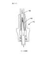
図1A~Bを参照すると、「針上に」カテーテル52を挿入するように構成された従来型のIV針組立体50を図示している。カテーテル52は、概して、生物学的部位内に挿入するための遠位端部56、近位端部58、及びそれらの間に延在している内腔を画定している可撓性壁を有するカテーテルチューブ54を含む。カテーテルチューブ54の近位端部58は、カテーテルハブ60に動作可能に連結されていることが多い。カテーテル52は、部分的にカテーテル52を針組立体50の針62上に同軸上に位置付けることにより、針組立体50に動作可能に連結可能であり得る。よって、カテーテル52は、皮膚、組織、及び血管壁を通して患者の血管内に針62と共に移動する。いったんカテーテルチューブ54が患者の血管内に進入すると、カテーテル52は、所望のように血管内へとさらに前進され得、針62は、カテーテル52から後退され得る。次に、カテーテル52は、患者上の適所に固定され得、IV流体供給部に接続され得る。いくつかの例において、カテーテル52は、IV流体供給部に接続するためのクランプ66及びルアー係止コネクタ68を有する延長チューブ64を含み得る。そのようなカテーテルは、典型的に、針62がカテーテル52から後退された後、針経路を封止する隔壁を含み、それにより患者からの血液もしくは体液がカテーテルから周囲環境へと漏出するのを防止するため、閉鎖系カテーテルと称されることが多い。1A-B, a conventional IV
本開示の実施形態は、カテーテルハブの種々の構成要素が共にスナップフィットされたカテーテルハブを構成する単純かつ信頼可能な方法を提供し、そのため接着剤及び超音波溶接が必要とされず、それによりカテーテル組立体の構築中に必要とされる出費及び労働力を低減する。本開示のいくつかの実施形態は、カテーテルハブ内の種々の構成要素の回転を抑制し、ならびに針挿入装置に対するカテーテルハブの回転を抑制するための機構をさらに提供する。本開示のいくつかの実施形態は、カテーテル組立体の一部分が患者の血管内に挿入されたとき、患者の皮膚との接触を改善するように構成された改善された翼設計を有するカテーテルハブを提供している。Embodiments of the present disclosure provide a simple and reliable method of constructing a catheter hub in which the various components of the catheter hub are snap-fit together, so that adhesives and ultrasonic welding are not required, thereby reducing the expense and labor required during construction of the catheter assembly. Some embodiments of the present disclosure further provide mechanisms for inhibiting rotation of the various components within the catheter hub, as well as inhibiting rotation of the catheter hub relative to the needle insertion device. Some embodiments of the present disclosure provide a catheter hub with an improved wing design configured to improve contact with the patient's skin when a portion of the catheter assembly is inserted into the patient's blood vessel.
本開示の一実施形態は、カテーテルハブ本体、隔壁、及び隔壁保持部を含むカテーテルハブ組立体を提供している。カテーテルハブ本体は、カテーテルチューブに動作可能に連結された遠位端部、近位端部、及びそれらの間に内側流体経路を画定している内側壁を有し得る。内側壁は、遠位端部に近位の小径部分と、近位端部に近位の大径部分との間の内側流体経路内に移行的段差を画定し得る。隔壁は、遠位端部及び近位端部を有し得る。隔壁は、隔壁の遠位端部が移行的段差に対して当接するように、内側流体経路内に位置付けられ得る。隔壁保持部は、カテーテルハブ本体の内側流体経路内に少なくとも部分的に受容可能であり得る。隔壁保持部は、外壁及び内壁を有し得る。隔壁保持部の外壁は、カテーテルハブ本体の内壁とかみ合うように形状決め及びサイズ決めされ得、カテーテルハブ本体に対する隔壁保持部の回転を抑制するように構成された1つ以上の横リブを含み得る。One embodiment of the present disclosure provides a catheter hub assembly including a catheter hub body, a septum, and a septum retainer. The catheter hub body may have a distal end operably coupled to a catheter tube, a proximal end, and an inner wall defining an inner fluid path therebetween. The inner wall may define a transition step in the inner fluid path between a smaller diameter portion proximal to the distal end and a larger diameter portion proximal to the proximal end. The septum may have a distal end and a proximal end. The septum may be positioned within the inner fluid path such that the distal end of the septum abuts against the transition step. The septum retainer may be at least partially receivable within the inner fluid path of the catheter hub body. The septum retainer may have an outer wall and an inner wall. The outer wall of the septum retainer may be shaped and sized to mate with the inner wall of the catheter hub body and may include one or more transverse ribs configured to inhibit rotation of the septum retainer relative to the catheter hub body.
本開示の一実施形態は、針組立体及び針ハウジングを有するカテーテル挿入装置をさらに提供している。針組立体は、尖鋭針先端を提示する挿入針を含み得る。挿入針は、針ハウジングに動作可能に連結され得、挿入針の尖鋭針先端が針ハウジングから延在している使用可能位置と、挿入針の尖鋭針先端が針ハウジング内に収容されている安全位置との間で移動可能であり得る。One embodiment of the present disclosure further provides a catheter insertion device having a needle assembly and a needle housing. The needle assembly may include an insertion needle presenting a sharpened needle tip. The insertion needle may be operably coupled to the needle housing and may be movable between a usable position in which the sharpened needle tip of the insertion needle extends from the needle housing and a safe position in which the sharpened needle tip of the insertion needle is contained within the needle housing.
一実施形態において、カテーテルハブ本体の近位端部は、カテーテルハブをカテーテル挿入装置に対して整列させ、かつカテーテル挿入装置の受動的解放機構へのカテーテルハブ組立体の連結を支援するように構成されたラグを含む。一実施形態において、隔壁は、内側流体経路を、その中を通過する針挿入装置からの針の除去時に封止するように構成されている。一実施形態において、隔壁は、孔を画定している内側表面を含む。一実施形態において、隔壁は、針の除去時に隔壁の再封止を支援するようにカテーテルハブの内側壁により円周方向に圧迫される。In one embodiment, the proximal end of the catheter hub body includes a lug configured to align the catheter hub with respect to the catheter insertion device and to assist in coupling the catheter hub assembly to a passive release mechanism of the catheter insertion device. In one embodiment, the septum is configured to seal the inner fluid path upon removal of a needle from the needle insertion device passing therethrough. In one embodiment, the septum includes an inner surface defining an aperture. In one embodiment, the septum is circumferentially compressed by an inner wall of the catheter hub to assist in resealing the septum upon removal of the needle.
一実施形態において、カテーテルハブ本体の内側は、側部ポートをさらに画定している。一実施形態において、カテーテル組立体は、側部ポートに動作可能に連結された延長チュービングをさらに含み、延長チューブの内腔は、内側流体経路と流体連通している。一実施形態において、カテーテル組立体は、延長チューブに動作可能に連結されており、かつ延長チューブを選択的に閉塞して、延長チューブ内腔を通した流れを抑制するように構成された延長チューブクランプをさらに含む。In one embodiment, the interior of the catheter hub body further defines a side port. In one embodiment, the catheter assembly further includes extension tubing operably coupled to the side port, the lumen of the extension tube being in fluid communication with the interior fluid pathway. In one embodiment, the catheter assembly further includes an extension tube clamp operably coupled to the extension tube and configured to selectively occlude the extension tube to inhibit flow through the extension tube lumen.
一実施形態において、カテーテル組立体は、延長チューブの内腔に動作可能に連結されており、かつこれと流体連通している針なしコネクタをさらに含む。一実施形態において、針なしコネクタは、能動的開口位置と付勢された閉鎖位置との間で移動可能である。一実施形態において、カテーテル組立体は、針なしコネクタに動作可能に連結された通気キャップをさらに含む。一実施形態において、通気キャップは、針なしコネクタが閉鎖されたままである第1の保存位置と、針なしコネクタが開口し、それによりカテーテル組立体内に閉じ込められた空気を通気する第2の能動的押し下げ位置との間で移動するように構成されている。In one embodiment, the catheter assembly further includes a needleless connector operably coupled to and in fluid communication with the lumen of the extension tube. In one embodiment, the needleless connector is movable between an active open position and a biased closed position. In one embodiment, the catheter assembly further includes a vent cap operably coupled to the needleless connector. In one embodiment, the vent cap is configured to move between a first stored position in which the needleless connector remains closed and a second actively depressed position in which the needleless connector opens, thereby venting air trapped within the catheter assembly.
本開示の別の実施形態は、カテーテルハブ本体、隔壁、及び隔壁保持部を含むカテーテルハブ組立体を提供している。カテーテルハブ本体は、カテーテルチューブに動作可能に連結された遠位端部、近位端部、及びそれらの間に内側流体経路を画定している内側壁を有し得る。内側壁は、遠位端部に近位の小径部分と、近位端部に近位の大径部分との間の内側流体経路内に移行的段差を画定し得る。隔壁は、遠位端部及び近位端部を有し得る。隔壁は、隔壁の遠位端部が移行的段差に対して当接するように、内側流体経路内に位置付けられ得る。隔壁保持部は、カテーテルハブ本体の内側流体経路内に少なくとも部分的に受容可能であり得、かつ隔壁を内側流体経路内の適所に固定するように構成され得る。隔壁保持部は、外壁及び内壁を有し得る。外壁は、カテーテルハブ本体の内壁とかみ合うように形状決め及びサイズ決めされ得、かつカテーテルハブ本体に対する隔壁保持部の回転を抑制するように構成された1つ以上の横リブを含み得る。内壁は、カテーテルハブ組立体をカテーテル挿入装置に選択的に連結するように形状決め及びサイズ決めされ得、かつカテーテル挿入装置に対する隔壁保持部の回転を抑制するように構成された1つ以上の横突起を含み得る。一実施形態において、1つ以上の横リブにより提供された摩擦抵抗は、隔壁保持部が、カテーテルハブ本体に対して回転する前に、カテーテル挿入装置に対して回転するように構成されるように、1つ以上の横突起により提供された摩擦抵抗を上回り得る。Another embodiment of the present disclosure provides a catheter hub assembly including a catheter hub body, a septum, and a septum retainer. The catheter hub body may have a distal end operably coupled to a catheter tube, a proximal end, and an inner wall defining an inner fluid path therebetween. The inner wall may define a transition step in the inner fluid path between a smaller diameter portion proximal to the distal end and a larger diameter portion proximal to the proximal end. The septum may have a distal end and a proximal end. The septum may be positioned in the inner fluid path such that the distal end of the septum abuts against the transition step. The septum retainer may be at least partially receivable within the inner fluid path of the catheter hub body and may be configured to secure the septum in place within the inner fluid path. The septum retainer may have an outer wall and an inner wall. The outer wall may be shaped and sized to mate with the inner wall of the catheter hub body and may include one or more transverse ribs configured to inhibit rotation of the septum retainer relative to the catheter hub body. The inner wall may be shaped and sized to selectively couple the catheter hub assembly to a catheter insertion device and may include one or more transverse protrusions configured to inhibit rotation of the septum retainer relative to the catheter insertion device. In one embodiment, the frictional resistance provided by the one or more transverse ribs may exceed the frictional resistance provided by the one or more transverse protrusions such that the septum retainer is configured to rotate relative to the catheter insertion device before rotating relative to the catheter hub body.
本開示の一実施形態は、カテーテル挿入装置を含む閉鎖系カテーテル組立体をさらに提供している。カテーテル挿入装置は、針組立体及び針ハウジングを含み得る。針組立体は、尖鋭針先端を提示する挿入針を含み得る。挿入針は、針ハウジングに動作可能に連結され得、かつ挿入針の尖鋭針先端が針ハウジングから延在している使用可能位置と、挿入針の尖鋭針先端が針ハウジング内に収容されている安全位置との間で移動可能であり得る。An embodiment of the present disclosure further provides a closed system catheter assembly including a catheter insertion device. The catheter insertion device may include a needle assembly and a needle housing. The needle assembly may include an insertion needle presenting a sharpened needle tip. The insertion needle may be operably coupled to the needle housing and may be movable between a usable position in which the sharpened needle tip of the insertion needle extends from the needle housing and a safe position in which the sharpened needle tip of the insertion needle is contained within the needle housing.
一実施形態において、カテーテルハブ本体の近位端部は、カテーテルハブをカテーテル挿入装置に対して整列させ、かつカテーテル挿入装置の受動的解放機構へのカテーテルハブ組立体の連結を支援するように構成されたラグを含む。一実施形態において、内側流体経路を、その中を通過するカテーテル挿入装置の挿入針の除去時に封止するように構成され得る。一実施形態において、隔壁は、孔を画定している内側表面を含み得る。一実施形態において、隔壁は、挿入針の除去時に、隔壁の再封止を支援するようにカテーテルハブの内側壁により円周方向に圧迫され得る。In one embodiment, the proximal end of the catheter hub body includes a lug configured to align the catheter hub with respect to the catheter insertion device and to assist in coupling the catheter hub assembly to a passive release mechanism of the catheter insertion device. In one embodiment, the inner fluid path may be configured to seal upon removal of an insertion needle of the catheter insertion device passing therethrough. In one embodiment, the septum may include an inner surface defining an aperture. In one embodiment, the septum may be circumferentially compressed by an inner wall of the catheter hub to assist in resealing the septum upon removal of the insertion needle.
一実施形態において、カテーテルハブ本体の内側壁は、側部ポートを画定し得る。一実施形態において、延長チューブは、側部ポートに動作可能に連結され得、延長チューブの内腔は、内側流体経路と流体連通している。一実施形態において、延長チューブクランプは、延長チューブに動作可能に連結され得、延長チューブを選択的に閉塞して、延長チューブ内腔を通した流れを抑制するように構成され得る。一実施形態において、針なしコネクタは、延長チューブの内腔に動作可能に連結され得、かつこれと流体連通し得る。一実施形態において、針なしコネクタは、能動的開口位置と付勢された閉鎖位置との間で移動可能であり得る。一実施形態において、カテーテルハブ組立体は、針なしコネクタに動作可能に連結された通気キャップをさらに含み得る。一実施形態において、通気キャップは、針なしコネクタが閉鎖されたままである第1の保存位置と、針なしコネクタが開口し、それによりカテーテルハブ組立体内に閉じ込められた空気を通気する第2の能動的押し下げ位置との間で移動するように構成され得る。In one embodiment, the inner wall of the catheter hub body may define a side port. In one embodiment, an extension tube may be operably coupled to the side port, with the lumen of the extension tube in fluid communication with the inner fluid path. In one embodiment, an extension tube clamp may be operably coupled to the extension tube and configured to selectively occlude the extension tube to inhibit flow through the extension tube lumen. In one embodiment, a needleless connector may be operably coupled to and in fluid communication with the lumen of the extension tube. In one embodiment, the needleless connector may be movable between an active open position and a biased closed position. In one embodiment, the catheter hub assembly may further include a vent cap operably coupled to the needleless connector. In one embodiment, the vent cap may be configured to move between a first stored position in which the needleless connector remains closed and a second active depressed position in which the needleless connector opens, thereby venting air trapped within the catheter hub assembly.
本開示の別の実施形態は、カテーテルハブ及び翼組立体を含む、対象の血管内に挿入するように構成されたカテーテル組立体を提供している。カテーテルハブは、カテーテルチューブに動作可能に連結された遠位端部、及びカテーテル挿入装置に動作可能に連結されるように構成された近位端部を有し得る。翼組立体は、カテーテルハブに動作可能に連結され得、かつ一対の可撓性翼部、踵部分、及びカラーを含み得る。一対の可撓性翼部は、カテーテルハブの中心軸から外方に延在し得る。踵部分は、一対の可撓性翼部の近位端部からカテーテルハブの近位端部に向かって延在し得る。カラーは、カテーテルハブの中心軸の周りを巻包し得る。一対の翼部の底表面及び踵部分の底表面は、カテーテルチューブが対象の血管内に挿入されたときに略真っ直ぐであり、かつ接触面が対象の皮膚に対して略平行であるように、カテーテルチューブの軸に対して角度付きである接触面を形成し得る。Another embodiment of the present disclosure provides a catheter assembly configured for insertion into a blood vessel of a subject, the catheter assembly including a catheter hub and a wing assembly. The catheter hub may have a distal end operably coupled to a catheter tube and a proximal end configured to be operably coupled to a catheter insertion device. The wing assembly may be operably coupled to the catheter hub and may include a pair of flexible wings, a heel portion, and a collar. The pair of flexible wings may extend outwardly from a central axis of the catheter hub. The heel portion may extend from a proximal end of the pair of flexible wings toward a proximal end of the catheter hub. The collar may wrap around the central axis of the catheter hub. A bottom surface of the pair of wings and a bottom surface of the heel portion may form a contact surface that is generally straight when the catheter tube is inserted into a blood vessel of a subject, and that is angled with respect to the axis of the catheter tube such that the contact surface is generally parallel to the skin of the subject.
本開示の一実施形態は、カテーテル挿入装置を含む閉鎖系カテーテル組立体をさらに提供している。カテーテル挿入装置は、針組立体及び針ハウジングを含み得る。針組立体は、尖鋭針先端を提示する挿入針を含み得る。挿入針は、針ハウジングに動作可能に連結され得、かつ挿入針の尖鋭針先端が針ハウジングから延在している使用可能位置と、挿入針の尖鋭針先端が針ハウジング内に収容されている安全位置との間で移動可能であり得る。An embodiment of the present disclosure further provides a closed system catheter assembly including a catheter insertion device. The catheter insertion device may include a needle assembly and a needle housing. The needle assembly may include an insertion needle presenting a sharpened needle tip. The insertion needle may be operably coupled to the needle housing and may be movable between a usable position in which the sharpened needle tip of the insertion needle extends from the needle housing and a safe position in which the sharpened needle tip of the insertion needle is contained within the needle housing.
一実施形態において、接触面は、7~9度の範囲でカテーテルチューブの軸からオフセットされ得る。一実施形態において、接触面は、およそ8度でカテーテルチューブの軸からオフセットされ得る。一実施形態において、一対の翼部の遠位部分は、対象の皮膚との接触を改善するようにカテーテルチューブの軸に対して略直角に延在している略真っ直ぐな線を形成し得る。別の実施形態において、一対の翼部の遠位部分は、翼部の遠位縁部がカテーテルチューブに近位の一対の翼部の遠位部分よりもさらに遠位に延在するように、緩い円弧を形成するように凹状であり得る。一実施形態において、一対の翼部の上表面は、臨床医がカテーテル組立体を把持することを支援するように構成された凹状表面を画定し得る。一実施形態において、翼組立体は、カテーテルハブよりも低い弾性率を有し得る。一実施形態において、テクスチャパターンは、カテーテルチューブが対象の血管内に挿入されたときに対象の皮膚との摩擦抵抗を増加させるように接触面内に形成され得る。一実施形態において、テクスチャパターンは、平坦または滑らかな表面と共に生じ得る汗の蓄積を防止することを支援し得る。一実施形態において、テクスチャパターンは、不快感を生じ得る高圧領域の生成を抑制する。一実施形態において、翼組立体は、カテーテルハブ上に一体的に成形されている。一実施形態において、カラーは、カテーテルハブの近位部分の周りを少なくとも部分的に巻包している。一実施形態において、カテーテルハブは、一対の可撓性翼部に対する構造的な補強を提供するように構成された1つ以上のレッジを含み得る。In one embodiment, the contact surface may be offset from the axis of the catheter tube in the range of 7-9 degrees. In one embodiment, the contact surface may be offset from the axis of the catheter tube by approximately 8 degrees. In one embodiment, the distal portion of the pair of wings may form a generally straight line extending generally perpendicular to the axis of the catheter tube to improve contact with the subject's skin. In another embodiment, the distal portion of the pair of wings may be concave to form a gentle arc such that the distal edge of the wing extends further distally than the distal portion of the pair of wings proximal to the catheter tube. In one embodiment, the upper surface of the pair of wings may define a concave surface configured to assist the clinician in gripping the catheter assembly. In one embodiment, the wing assembly may have a lower modulus of elasticity than the catheter hub. In one embodiment, a textured pattern may be formed in the contact surface to increase frictional resistance with the subject's skin when the catheter tube is inserted into the subject's blood vessel. In one embodiment, the textured pattern may help prevent sweat accumulation that may occur with flat or smooth surfaces. In one embodiment, the textured pattern inhibits the creation of high pressure areas that may cause discomfort. In one embodiment, the wing assembly is integrally molded onto the catheter hub. In one embodiment, the collar is at least partially wrapped around a proximal portion of the catheter hub. In one embodiment, the catheter hub may include one or more ledges configured to provide structural reinforcement for the pair of flexible wings.
本開示の別の実施形態は、針なしコネクタに動作可能に連結されるように構成されており、かつ保存位置と能動的押し下げ通気位置との間の針なしコネクタに対して移動可能である通気キャップを提供している。通気キャップは、ノーズ部、押し板、及び1つ以上の弾性針なしコネクタ係合アームを含み得る。ノーズ部は、通気キャップが能動的押し下げ通気位置まで押し下げされたときに、少なくとも部分的に針なしコネクタ内に挿入されるように構成され得る。押し板は、ノーズ部の近位端部に動作可能に連結され得、かつ空気透過性膜を備える通気口を画定し得る。1つ以上の弾性針なしコネクタ係合アームは、ノーズ部に動作可能に連結され得、かつ針なしコネクタの一部分を把持するように構成され得、1つ以上の弾性針なしコネクタ係合アームは、通気キャップを保存位置へと付勢する。Another embodiment of the present disclosure provides a vent cap configured to be operably coupled to the needleless connector and movable relative to the needleless connector between a storage position and an active depressed vent position. The vent cap may include a nose, a push plate, and one or more resilient needleless connector engagement arms. The nose may be configured to be at least partially inserted into the needleless connector when the vent cap is depressed to the active depressed vent position. The push plate may be operably coupled to a proximal end of the nose and may define a vent port with an air permeable membrane. The one or more resilient needleless connector engagement arms may be operably coupled to the nose and configured to grip a portion of the needleless connector, the one or more resilient needleless connector engagement arms biasing the vent cap to the storage position.
一実施形態において、通気キャップは、カテーテルチューブ、カテーテルハブ、延長チューブ、及び針なしコネクタを含む閉鎖系カテーテル組成物に選択的に連結されている。一実施形態において、1つ以上の弾性針なしコネクタ係合アームは、針なしコネクタへの1つ以上の弾性針なしコネクタ係合アームの把持を改善するための隆起部を含み得る。一実施形態において、能動的押し下げ通気位置への通気キャップの移動により、針なしコネクタ内に閉じ込められた空気を放出させることができる。一実施形態において、能動的押し下げ通気位置への通気キャップの移動は、1つ以上の弾性針なしコネクタ係合アームを離れるように促し、能動的押し下げ位置からの解放時に、1つ以上の弾性針なしコネクタ係合アームの弾性が、通気キャップを保存位置に戻すように付勢する。一実施形態において、通気キャップは、使用後に、針なしコネクタから除去可能である。一実施形態において、通気キャップのノーズ部は、能動的押し下げ通気位置に移動されたときに針なしコネクタとの流体密封を改善するようにテーパ状である。In one embodiment, the vent cap is selectively coupled to a closed system catheter composition including a catheter tube, a catheter hub, an extension tube, and a needleless connector. In one embodiment, the one or more elastic needleless connector engagement arms may include a ridge to improve grip of the one or more elastic needleless connector engagement arms to the needleless connector. In one embodiment, movement of the vent cap to the active depressed vent position may allow air trapped within the needleless connector to be released. In one embodiment, movement of the vent cap to the active depressed vent position urges the one or more elastic needleless connector engagement arms to move apart, and upon release from the active depressed position, the resilience of the one or more elastic needleless connector engagement arms biases the vent cap back to the storage position. In one embodiment, the vent cap is removable from the needleless connector after use. In one embodiment, the nose of the vent cap is tapered to improve a fluid-tight seal with the needleless connector when moved to the active depressed vent position.
一実施形態において、ノーズ部は、空気透過性膜により一端に封止された通気経路を含む。一実施形態において、通気経路は、透明な材料及び半透明な材料のうちの少なくとも1つにより構成されている。一実施形態において、通気キャップは、流体が通気経路内に流れるときにフラッシュバック指標を提供するように構成されている。一実施形態において、押し板は、空気が通気経路から漏出するための流体経路を提供するように構成されたアイレットを画定し得る。In one embodiment, the nose portion includes a vent passage sealed at one end by an air permeable membrane. In one embodiment, the vent passage is constructed from at least one of a transparent material and a translucent material. In one embodiment, the vent cap is configured to provide a flashback indication when fluid flows into the vent passage. In one embodiment, the push plate may define an eyelet configured to provide a fluid path for air to escape from the vent passage.
本開示の別の実施形態は、カテーテル挿入装置及び閉鎖系カテーテルを含む静脈内カテーテル組立体を提供している。カテーテル挿入装置は、針組立体及び針ハウジングを含み得る。針組立体は、尖鋭針先端を提示する挿入針を含み得る。挿入針は、針ハウジングに動作可能に連結され得、かつ挿入針の尖鋭針先端が針ハウジングから延在している使用可能位置と、挿入針の尖鋭針先端が針ハウジング内に収容されている安全位置との間で移動可能であり得る。挿入針は、血液が間を流れることを可能にして、カテーテルの配置の主な指標を提供するように構成された挿入針の尖鋭針先端に近位の刻み目位置を提示する構造を含み得る。針組立体は、カテーテルの配置の二次的な指標を提供するように挿入針の内腔と連通しているフラッシュチャンバを画定している構造を含み得る。Another embodiment of the present disclosure provides an intravenous catheter assembly including a catheter insertion device and a closed system catheter. The catheter insertion device may include a needle assembly and a needle housing. The needle assembly may include an insertion needle presenting a sharpened needle tip. The insertion needle may be operatively coupled to the needle housing and may be movable between a ready position in which the sharpened needle tip of the insertion needle extends from the needle housing and a safe position in which the sharpened needle tip of the insertion needle is contained within the needle housing. The insertion needle may include structure presenting a notch location proximal to the sharpened needle tip of the insertion needle configured to allow blood to flow therebetween to provide a primary indication of catheter placement. The needle assembly may include structure defining a flash chamber in communication with the lumen of the insertion needle to provide a secondary indication of catheter placement.
閉鎖系カテーテルは、カテーテルチューブ、カテーテルハブ、延長チューブ、針なしコネクタ、及び通気キャップを含み得る。通気キャップは、空気透過性バリアにより一端で封止された通気経路を画定している壁を含み得る。通気キャップは、針なしコネクタが閉鎖位置にある第1の保存位置と、針なしコネクタが開口位置に移動され、それにより閉鎖系カテーテル内に閉じ込められた空気を通気し、かつ血液が通気経路内に流れることを可能にして、カテーテルの配置の三次的な指標を提供する第2の能動的押し下げ位置との間で移動可能であり得る。The closed catheter may include a catheter tube, a catheter hub, an extension tube, a needleless connector, and a vent cap. The vent cap may include a wall defining a vent path sealed at one end by an air permeable barrier. The vent cap may be movable between a first stored position in which the needleless connector is in a closed position and a second actively depressed position in which the needleless connector is moved to an open position, thereby venting air trapped within the closed catheter and allowing blood to flow into the vent path to provide a tertiary indication of catheter placement.
本開示の方法は、
挿入針及びその周りに同軸上に位置付けられたカテーテルチューブを対象の血管内に導入するステップであって、環状空間が挿入針と同軸上に位置付けられたカテーテルチューブとのそれらの間に存在する、導入するステップ、
挿入針内に画定された刻み目を通した環状空間内への血液の流れを介して適切なカテーテルの配置の主な指標を受容するステップ、
挿入針の内腔を通したフラッシュチャンバ内への血液の流れを介して適切なカテーテルの配置の二次的な指標を受容するステップ、
通気キャップを保存位置から能動的押し下げ位置へと移動させることにより静脈内カテーテル組立体内からの空気を通気するステップ、ならびに
通気キャップ内への血液の流れを介して適切なカテーテルの配置の三次的な指標を受容するステップ、のうちの1つ以上を含む、フラッシュチャンバ及び通気キャップを含む静脈内カテーテル組立体を使用することを提供している。 The method of the present disclosure comprises:
introducing an insertion needle and a catheter tube coaxially positioned therearound into a blood vessel of a subject, wherein an annular space exists between the insertion needle and the catheter tube;
receiving a primary indication of proper catheter placement via blood flow into the annular space through a score defined in the insertion needle;
receiving a secondary indication of proper catheter placement via the flow of blood through the lumen of the insertion needle and into the flash chamber;
The present invention provides for the use of an intravenous catheter assembly including a flash chamber and a vent cap, the use of which includes one or more of the following steps: venting air from within the intravenous catheter assembly by moving the vent cap from a stored position to an actively depressed position; and receiving a tertiary indication of proper catheter placement via blood flow into the vent cap.
上の要約は、本開示の各図示されている実施形態またはあらゆる実装を記載することを企図していない。下記に続く図及び詳細な説明は、これらの実施形態をより具体的に実証する。The above summary is not intended to describe each illustrated embodiment or every implementation of the present disclosure. The figures and detailed description that follow more particularly demonstrate these embodiments.
添付の図と関連して、本開示の種々の実施形態についての下記の詳細な説明を考察することで、本開示をより完全に理解することができる。A more complete understanding of the present disclosure can be obtained by considering the following detailed description of various embodiments of the present disclosure in conjunction with the accompanying drawings.
本開示の実施形態は、種々の変形例及び代替的な形態に従っているが、図中の例によって示されているそれらの仕様は、詳細に記載されるだろう。しかしながら、本開示を記載されている特定の実施形態に限定することを企図していないことが理解されるべきである。それどころか、添付の特許請求の範囲により定義されているような本開示の精神及び範囲内に該当するあらゆる変形例、等価物、及び代替例を含むことを企図している。While embodiments of the present disclosure are amenable to various modifications and alternative forms, the specifications of which are illustrated by way of example in the drawings will be described in detail. It should be understood, however, that it is not intended to limit the disclosure to the particular embodiments described. On the contrary, it is intended to cover all modifications, equivalents, and alternatives falling within the spirit and scope of the present disclosure as defined by the appended claims.
図1A~Bを参照すると、従来型のIVカテーテル組立体20が図示されている。従来型のIVカテーテル組立体20の詳細は、上の背景の節に記載されている。Referring to Figures 1A-B, a conventional IV catheter assembly 20 is illustrated. Details of the conventional IV catheter assembly 20 are described in the Background section above.
図2A~Gを参照すると、本開示の実施形態によるカテーテル組立体100が図示されている。一実施形態において、カテーテル組立体100は、閉鎖系カテーテルであり得る。図3A~Gを参照すると、本開示の実施形態による閉鎖系カテーテル組立体101が図示されている。一実施形態において、閉鎖系カテーテル組立体101は、カテーテル挿入装置102に動作可能に連結されたカテーテル組立体100を含み得る。Referring to Figures 2A-G, a catheter assembly 100 according to an embodiment of the present disclosure is illustrated. In one embodiment, the catheter assembly 100 can be a closed system catheter. Referring to Figures 3A-G, a closed system catheter assembly 101 according to an embodiment of the present disclosure is illustrated. In one embodiment, the closed system catheter assembly 101 can include a catheter assembly 100 operably coupled to a catheter insertion device 102.
I.カテーテル挿入装置
カテーテル挿入装置102は、カテーテルチューブ108の一部分が同軸上に乗っている挿入針104を提供し得る。種々の種類のカテーテル挿入装置102は、JELCOの商標下で、米国ミネソタ州セントポール所在のSmiths Medical ASD,Inc.により販売されている。カテーテル挿入装置102の一実施形態(図1A~Bに図示されているもの等)は、米国特許第7,291,130号及び同第8,257,322号(INTUITIVの商標下で、Smiths Medical ASD,Inc.により販売されているIVカテーテル挿入装置を図示している)に記載されており、それらの両方は、参照により本明細書に組み込まれる。I. Catheter Insertion Device A catheter insertion device 102 may provide an insertion needle 104 on which a portion of a catheter tube 108 coaxially rides. Various types of catheter insertion devices 102 are sold by Smiths Medical ASD, Inc., St. Paul, Minnesota, USA under the trademark JELCO. One embodiment of a catheter insertion device 102 (such as that shown in Figures 1A-B) is described in U.S. Patent Nos. 7,291,130 and 8,257,322 (which illustrate an IV catheter insertion device sold by Smiths Medical ASD, Inc. under the trademark INTUITIV), both of which are incorporated herein by reference.
他の実施形態において、カテーテル挿入装置102は、挿入針104の尖鋭針先端106を収容する機能を果たし、不注意による針刺しの可能性を低減する、安全針組立体(図3A~G及び図4A~Bに図示されているもの等)を提供し得る。図4Aは、カテーテル組立体100がカテーテル挿入装置102に選択的に連結されている第1または使用可能位置にあるカテーテル挿入装置102を図示している。具体的には、カテーテルチューブ108及びカテーテルハブ110を含み得るカテーテル組立体100は、挿入針104の尖鋭針先端106がカテーテルチューブ108の遠位端部から突出している状態で、カテーテル挿入装置102の挿入針104上に位置付けられ得る。いくつかの実施形態において、保護シースもしくは針カバー(図示せず)は、カテーテル組立体100もしくはカテーテル挿入装置102のいずれかに動作可能に連結され得、かつ尖鋭針先端106上に位置付けられて、不要な針刺しを抑制し得る。カテーテル組立体100及びカテーテル挿入装置102を含み得る閉鎖系カテーテル組立体101は、密閉包装体内に含有された殺菌及び組み立て後の状態で使用するように提供され得る。In other embodiments, the catheter insertion device 102 may provide a safety needle assembly (such as that shown in FIGS. 3A-G and 4A-B) that serves to accommodate the sharpened needle tip 106 of the insertion needle 104 and reduce the possibility of an inadvertent needle stick. FIG. 4A illustrates the catheter insertion device 102 in a first or ready position in which the catheter assembly 100 is selectively coupled to the catheter insertion device 102. Specifically, the catheter assembly 100, which may include a catheter tube 108 and a catheter hub 110, may be positioned over the insertion needle 104 of the catheter insertion device 102 with the sharpened needle tip 106 of the insertion needle 104 protruding from the distal end of the catheter tube 108. In some embodiments, a protective sheath or needle cover (not shown) may be operably coupled to either the catheter assembly 100 or the catheter insertion device 102 and positioned over the sharpened needle tip 106 to inhibit unwanted needle sticks. The closed system catheter assembly 101, which may include the catheter assembly 100 and the catheter insertion device 102, may be provided for use in a sterile and assembled state contained within a hermetically sealed package.
カテーテルチューブ108を患者または対象の血管内に挿入するために、臨床医は、まず、閉鎖系カテーテル組立体101を包装体から除去する。針シースを除去して、カテーテルチューブ108の遠位端部から突出している挿入針104の尖鋭針先端106を露出させる。次に、臨床医は、対象の特定された部位を尖鋭針先端106により穿刺し、尖鋭針先端106が対象の血管に進入するまで、針104を前方に促す。いくつかの実施形態において、血液または体液の最初の量は、針104の内腔を通して通過し得、かつカテーテル組立体100及び/もしくはカテーテル挿入装置102に進入し得、そのため臨床医は、血液もしくは体液の「フラッシュバック」を見て血管内への進入を確認することができる。次に、カテーテル組立体100を針104上で遠位に移動させ、針104が静止して保持されたときにカテーテルチューブ108を対象の血管内に通すことができる。カテーテル組立体100が所望のように位置付けられた状態で、臨床医は、カテーテル組立体100を対象に対して略静止した状態で保持するそれらの間に、カテーテル挿入装置102の針組立体103を対象から離れるように近位に引っ張ることにより針104を後退させることができる。カテーテル挿入装置102の針104がカテーテル組立体100から分離され、かつ第2または安全位置と称される、カテーテル挿入装置102の針ハウジング105内に安全に収容されるまで、針組立体103を近位に引っ張ることができる。図4Bは、静脈内カテーテル組立体100及び安全位置を図示している。安全位置において、臨床医は、シャープコンテナ内にカテーテル挿入装置102を廃棄することができる。To insert the catheter tube 108 into a patient's or subject's blood vessel, the clinician first removes the closed system catheter assembly 101 from its packaging. The needle sheath is removed to expose the sharp needle tip 106 of the insertion needle 104 protruding from the distal end of the catheter tube 108. The clinician then pierces the identified site on the subject with the sharp needle tip 106 and urges the needle 104 forward until the sharp needle tip 106 enters the subject's blood vessel. In some embodiments, an initial amount of blood or bodily fluid may pass through the lumen of the needle 104 and enter the catheter assembly 100 and/or the catheter insertion device 102 so that the clinician can see a "flashback" of blood or bodily fluid to confirm entry into the vessel. The catheter assembly 100 may then be moved distally over the needle 104, and the catheter tube 108 may be threaded into the subject's blood vessel when the needle 104 is held stationary. With the catheter assembly 100 positioned as desired, the clinician can retract the needle 104 by pulling the needle assembly 103 of the catheter insertion device 102 proximally away from the subject while holding the catheter assembly 100 substantially stationary relative to the subject. The needle assembly 103 can be pulled proximally until the needle 104 of the catheter insertion device 102 is separated from the catheter assembly 100 and safely housed within the needle housing 105 of the catheter insertion device 102, referred to as the second or safe position. FIG. 4B illustrates the intravenous catheter assembly 100 and the safe position. In the safe position, the clinician can discard the catheter insertion device 102 in a sharps container.
本明細書で使用される場合、「遠位」という用語は、カテーテル挿入中に対象に最も近い閉鎖系カテーテル組立体101の針104に対して平行に位置するアクセスに沿った方向を指すことが理解されるべきである。反対に、本明細書で使用される場合、「近位」という用語は、カテーテルが遠位方向に対向する対象の血管内に挿入されたときに対象からさらに離れる針104に対して平行な軸に沿って位置する方向を指す。As used herein, the term "distal" should be understood to refer to a direction along the access that lies parallel to the needle 104 of the closed system catheter assembly 101 that is closest to the subject during catheter insertion. Conversely, as used herein, the term "proximal" refers to a direction that lies along an axis that is parallel to the needle 104 that is further away from the subject when the catheter is inserted into the subject's blood vessel in the opposing distal direction.
図5A~Cに図示されているように、針組立体103は、針ハブ262に動作可能に連結された挿入針104を含み得る。針104は、尖鋭遠位針先端106と近位端部264とのそれらの間に延在している内腔を画定している細長い円筒形状の金属構造を含み得る。尖鋭針先端106は、カテーテル挿入中に対象の皮膚を刺し通すように構成及び配置され得る。例えば、一実施形態において、尖鋭針先端106は、対象の皮膚、組織、及び血管壁を通して針104及びカテーテル挿入組立体102の一部分を貫通させるのに使用される貫通力を減少させるように設計されたV字点を含み得る。一実施形態において、針104の長さを延長させて、肥満患者内へのカテーテル組立体100の挿入を支援することができる。5A-C, the needle assembly 103 may include an insertion needle 104 operably coupled to a needle hub 262. The needle 104 may include an elongated cylindrical metal structure defining a lumen extending between a sharpened distal needle tip 106 and a proximal end 264. The sharpened needle tip 106 may be configured and arranged to pierce the skin of a subject during catheter insertion. For example, in one embodiment, the sharpened needle tip 106 may include a V-point designed to reduce the penetration force used to penetrate the needle 104 and a portion of the catheter insertion assembly 102 through the skin, tissue, and blood vessel walls of a subject. In one embodiment, the length of the needle 104 may be extended to aid in the insertion of the catheter assembly 100 into an obese patient.
針104は、移行部266に近位に位置する針104の一部とは異なる断面サイズ及び/または形状を有する移行部266をさらに含み得る。針104の外側表面が針軸の中心から測定されるように、針104の他の部分よりも大きい径方向位置まで延在するように、針104の対向する側部を圧着させるか、または別様に、針104の構造を分断させることにより、針移行部266(代替的に針ポンプまたはカニューレポンプと称される)を生成することができる。他の方法の中でも特に、針の外側に材料を加えることによる等、代替的な実施形態により、移行部266を異なるように形成することができる。The needle 104 may further include a transition portion 266 having a different cross-sectional size and/or shape than a portion of the needle 104 located proximal to the transition portion 266. The needle transition portion 266 (alternatively referred to as a needle pump or cannula pump) may be created by crimping opposing sides of the needle 104 or otherwise disrupting the structure of the needle 104 such that the outer surface of the needle 104 extends to a greater radial position, as measured from the center of the needle shaft, than other portions of the needle 104. Alternative embodiments may form the transition portion 266 differently, such as by adding material to the outside of the needle, among other methods.
針104の近位端部264は、針ハブ262に動作可能に連結され得る。針ハブ262は、臨床医がアクセスするために組み立てられたときに針ハウジング105の外側上に位置付けられる針把持部268に接続され得る。針ハブ262及び針把持部268は、針把持部268及び針ハブ262と同じ一体構造から形成され得る突起270により互いに動作可能に連結され得る。The proximal end 264 of the needle 104 may be operably coupled to a needle hub 262. The needle hub 262 may be connected to a needle gripper 268 that is positioned on the exterior of the needle housing 105 when assembled for access by a clinician. The needle hub 262 and the needle gripper 268 may be operably coupled to one another by a protrusion 270 that may be formed from the same unitary structure as the needle gripper 268 and the needle hub 262.
一実施形態において、針組立体103は、針104の尖鋭針先端106が対象の血管に進入したときにフラッシュバックの視覚的指標を提供するように構成され得る。この実施形態において、針ハブ262は、針104の内腔と流体連通しているフラッシュチャンバ272を含む。尖鋭針先端106がカテーテル挿入中に血管に進入すると、血液または体液は、血管から針内腔に進入し、針104を通してフラッシュチャンバ272内に近位に流れる。フラッシュチャンバ272は、フラッシュプラグ274により一端に封止され得る。フラッシュプラグ274は、空気の通過を可能にするが、液体の通過を抑制する空気透過性親水性材料から製造され得る。したがって、針内腔及びフラッシュチャンバ272内に存在する空気は、血液がフラッシュプラグ274に達するか、または別様に停止されるまで、流入する血液によりフラッシュプラグ274を通して押し下げられる。針ハブ262またはその一部分は、臨床医がフラッシュチャンバ272内の血液の存在を確認することを可能にするために透明または半透明材料から構成され得る。この点において、臨床医は、フラッシュチャンバ272内の血液の存在により針が対象の血液に進入したときに警告を受けることができる。In one embodiment, the needle assembly 103 may be configured to provide a visual indication of a flashback when the sharpened needle tip 106 of the needle 104 enters a blood vessel of a subject. In this embodiment, the needle hub 262 includes a flash chamber 272 in fluid communication with the lumen of the needle 104. When the sharpened needle tip 106 enters a blood vessel during catheter insertion, blood or bodily fluids enter the needle lumen from the blood vessel and flow proximally through the needle 104 into the flash chamber 272. The flash chamber 272 may be sealed at one end by a flash plug 274. The flash plug 274 may be fabricated from an air-permeable hydrophilic material that allows the passage of air but inhibits the passage of liquid. Thus, air present in the needle lumen and flash chamber 272 is pushed down through the flash plug 274 by the incoming blood until the blood reaches the flash plug 274 or is otherwise stopped. The needle hub 262, or a portion thereof, may be constructed from a transparent or translucent material to allow the clinician to confirm the presence of blood in the flash chamber 272. In this regard, the clinician can be alerted when the needle enters the subject's blood due to the presence of blood in the flash chamber 272.
一実施形態において、フラッシュチャンバ272以外の針組立体103の特徴は、尖鋭針先端106が対象の血液に進入したとの指標を提供することができる。例えば、針104は、刻み目276を含み得る。この実施形態において、血液の流れは、尖鋭針先端106が血管に進入したときに針内腔に進入する。血液が針内腔内に近位に流れると、一部の血液は、刻み目276を通して、針104の外側とカテーテルチューブ108の内側とのそれらの間に位置する環状空間内へと通過する。環状空間内の血液の存在は、カテーテルチューブ108の透明または半透明な部分を通して臨床医が確認することができ、尖鋭針先端106が血管内に存在するとの指標を提供することができる。In one embodiment, features of the needle assembly 103 other than the flash chamber 272 can provide an indication that the sharp needle tip 106 has entered the subject's blood. For example, the needle 104 can include an indentation 276. In this embodiment, blood flow enters the needle lumen when the sharp needle tip 106 enters the blood vessel. As blood flows proximally into the needle lumen, some blood passes through the indentation 276 into the annular space located between the outside of the needle 104 and the inside of the catheter tube 108. The presence of blood in the annular space can be seen by the clinician through a transparent or translucent portion of the catheter tube 108 and can provide an indication that the sharp needle tip 106 is present in the blood vessel.
図6A~Bに図示されているように、針ハウジング105は、近位端部280から遠位端部282まで延在している略円筒状の細長い本体278を有し得る。長手方向スロット284は、針ハウジング105の下側に沿って形成され得、かつ針ハウジング105の近位端部280近くの近位スロット端部286から、針ハウジング105の遠位端部282近くの遠位スロット端部288まで延在し得る。6A-B, the needle housing 105 may have a generally cylindrical elongated body 278 extending from a proximal end 280 to a distal end 282. A longitudinal slot 284 may be formed along the underside of the needle housing 105 and may extend from a proximal slot end 286 near the proximal end 280 of the needle housing 105 to a distal slot end 288 near the distal end 282 of the needle housing 105.
針組立体103は、針ハウジング105にスライド可能に連結され得る。例えば、針組立体103は、針組立体103が針ハウジング105から容易に分離するのを抑制し、さらに針組立体103が最小の抵抗で針ハウジング105の長手方向軸に沿ってスライドすることを可能にする方法で、針ハウジング105の外側表面の周りに嵌合するように適合された「C」字形状の断面を有し得る。一実施形態において、長手方向スロット284は、針組立体103の突起270をスライド可能に受容し得、針把持部268は、針ハウジング105の外側に位置付けられ、針ハブ262及び針104の少なくとも一部分は、針ハウジング105に対して内側に位置付けられ、それによりこれらの特徴部を少なくとも部分的に収容し得る。したがって、針組立体103は、長手方向スロット284に沿ってスライドして、針組立体103が針ハウジング105の長手方向軸の周りで回転することを制限するように構成され得る。長手方向スロット284内にスライド可能に受容された突起270は、針ハウジング105の長手方向軸に対して略平行な針ハブ262の直線移動を可能にするが、針ハウジング105に対する針組立体103の回転移動を制限する。The needle assembly 103 may be slidably coupled to the needle housing 105. For example, the needle assembly 103 may have a "C" shaped cross-section adapted to fit around the outer surface of the needle housing 105 in a manner that inhibits the needle assembly 103 from easily separating from the needle housing 105, yet allows the needle assembly 103 to slide along the longitudinal axis of the needle housing 105 with minimal resistance. In one embodiment, the longitudinal slot 284 may slidably receive the protrusion 270 of the needle assembly 103, the needle grip 268 may be positioned outside the needle housing 105, and the needle hub 262 and at least a portion of the needle 104 may be positioned inside relative to the needle housing 105, thereby at least partially accommodating these features. Thus, the needle assembly 103 may be configured to slide along the longitudinal slot 284 to restrict the needle assembly 103 from rotating around the longitudinal axis of the needle housing 105. The protrusion 270, slidably received within the longitudinal slot 284, allows linear movement of the needle hub 262 generally parallel to the longitudinal axis of the needle housing 105, but limits rotational movement of the needle assembly 103 relative to the needle housing 105.
長手方向スロット284は、使用可能位置(図6Aに図示されているような)と安全位置(図6Bに図示されているような)との間の針ハウジング105に対する動作で針組立体103を誘導し得る。使用可能位置において、針104の一部分は、針104の尖鋭針先端106が針ハウジング105を越えて突出するように、針ハウジング105から延在している。安全位置において、針104は後退され、尖鋭針先端106は、不注意による針刺しの可能性を減少または除去することを企図した方法で、針ハウジング105内に収容される。The longitudinal slot 284 may guide the needle assembly 103 in movement relative to the needle housing 105 between a usable position (as shown in FIG. 6A) and a safe position (as shown in FIG. 6B). In the usable position, a portion of the needle 104 extends from the needle housing 105 such that the sharpened needle tip 106 of the needle 104 protrudes beyond the needle housing 105. In the safe position, the needle 104 is retracted and the sharpened needle tip 106 is contained within the needle housing 105 in a manner intended to reduce or eliminate the possibility of an inadvertent needle stick.
カテーテル挿入装置102は、針104を使用してカテーテル組立体100を挿入した後に尖鋭針先端106がアクセスされるのを抑制するように、尖鋭針先端106に近位の位置で針組立体に係合する針係止部290を含み得る。このように、針104が安全位置にあるとき、尖鋭針先端106へのアクセスは抑制される。よって、針係止部290は、安全位置で針組立体103を針ハウジング105とかみ合わせるように構成され得る。一実施形態において、針係止部290は、突起270に係合するように、近位スロット端部286において針ハウジング105の近位部分上に位置付けられ得る。この目的のために、いくつかの異なる種類の係止機構を使用することができる。例えば、一実施形態において、針ハウジング105の長手方向スロット284は、内部に画定されたボトルネック292を有し得、長手方向スロット284のボトルネック292は、長手方向スロット284の残りの部分よりも狭い幅を一般に有する。針組立体103の突起270は、くさびの頂点が使用可能位置にあるときにボトルネック292に面する形状で、三角形またはくさび状であり得る。安全位置までスライドさせるための労力で、針組立体103に外部力が加えられたとき、突起270のくさびの頂点は、ボトルネック292に接触し得る。突起270の幅よりも狭い幅を有し得るボトルネック292は、最初、ボトルネック292を通した突起270の移動に耐え得る。しかしながら、十分な力により、くさび形状の突起270は、ボトルネック292を一時的に変形させ得、それにより突起270がボトルネック292を通して通過することを可能にする。例えば、一実施形態において、くさび形状の突起270とボトルネック292との間の相互作用により、突起270がボトルネック292を通して通過したとの、聞き取れる「クリック」音、触覚または視覚的指標を生成し得る。その後、突起270は、ボトルネック292を通して反対方向に戻るように通過することはできず、針104は、針ハウジング105に対して安全位置に係止されるだろう。The catheter insertion device 102 may include a needle lock 290 that engages the needle assembly at a location proximal to the sharp needle tip 106 to inhibit access to the sharp needle tip 106 after inserting the catheter assembly 100 using the needle 104. In this manner, access to the sharp needle tip 106 is inhibited when the needle 104 is in the safety position. Thus, the needle lock 290 may be configured to mate the needle assembly 103 with the needle housing 105 in the safety position. In one embodiment, the needle lock 290 may be positioned on the proximal portion of the needle housing 105 at the proximal slot end 286 to engage the protrusion 270. Several different types of locking mechanisms may be used for this purpose. For example, in one embodiment, the longitudinal slot 284 of the needle housing 105 may have a bottleneck 292 defined therein, the bottleneck 292 of the longitudinal slot 284 generally having a narrower width than the remainder of the longitudinal slot 284. The projection 270 of the needle assembly 103 may be triangular or wedge-shaped, with the apex of the wedge facing the bottleneck 292 when in the ready position. When an external force is applied to the needle assembly 103 in an effort to slide it to the safe position, the apex of the wedge of the projection 270 may contact the bottleneck 292. The bottleneck 292, which may have a width narrower than the width of the projection 270, may initially resist movement of the projection 270 through the bottleneck 292. However, with sufficient force, the wedge-shaped projection 270 may temporarily deform the bottleneck 292, thereby allowing the projection 270 to pass through the bottleneck 292. For example, in one embodiment, the interaction between the wedge-shaped projection 270 and the bottleneck 292 may produce an audible "click" sound, a tactile or visual indication that the projection 270 has passed through the bottleneck 292. Thereafter, the projection 270 cannot pass back through the bottleneck 292 in the opposite direction, and the needle 104 will be locked in a safe position relative to the needle housing 105.
いくつかの実施形態において、カテーテル挿入装置102は、端キャップ263(図3A~Gに図示されているような)を含み得る。端キャップ263は、針把持部268及び/または針ハブ262に連結され得、それにより針ハウジング105の近位端部280を覆う。端キャップ263は、臨床医が本明細書で考察されているようなカテーテル挿入手技中に押すことができる表面を提供し得る近位端部265を有し得る。In some embodiments, the catheter insertion device 102 may include an end cap 263 (as illustrated in FIGS. 3A-G). The end cap 263 may be coupled to the needle gripper 268 and/or the needle hub 262, thereby covering the proximal end 280 of the needle housing 105. The end cap 263 may have a proximal end 265 that may provide a surface against which a clinician can press during a catheter insertion procedure as discussed herein.
図7A~Bを参照すると、一実施形態において、静脈内カテーテル組立体100は、受動的解放機構298を含み得る。受動的解放機構298は、使用可能位置(図7Aに図示されているような)においてカテーテルハブ110をカテーテル挿入装置102に連結し、かつカテーテルハブ110をカテーテル挿入装置102及び安全位置(図7Bに図示されているような)からを解放するように構成され得る。いくつかの実施形態において、受動的解放機構298は、カテーテル挿入装置102の尖鋭針先端106が、尖鋭針先端106へのアクセスが抑制される安全位置に来るまでカテーテル挿入装置102からのカテーテル組立体100の解放を抑制する1つ以上のカテーテルハブ接触部を含み得る。カテーテル挿入装置102からのカテーテル組立体100の解放は、針104を安全に後退させることを除く、追加のステップを行う必要なく、カテーテル挿入手技中に生じ得る。この点において、カテーテルは、「受動的な」安全を得るために、臨床医が「受動的に」解放することができる。例示によって、カテーテル組立体100は、臨床医が針104をカテーテル組立体100から後退させながら、臨床医がカテーテル挿入装置102の一部分上で引っ張るときに解放され得る。7A-B, in one embodiment, the intravenous catheter assembly 100 may include a passive release mechanism 298. The passive release mechanism 298 may be configured to couple the catheter hub 110 to the catheter insertion device 102 in a ready-to-use position (as shown in FIG. 7A) and release the catheter hub 110 from the catheter insertion device 102 and a safe position (as shown in FIG. 7B). In some embodiments, the passive release mechanism 298 may include one or more catheter hub contacts that inhibit release of the catheter assembly 100 from the catheter insertion device 102 until the sharpened needle tip 106 of the catheter insertion device 102 is in a safe position where access to the sharpened needle tip 106 is inhibited. Release of the catheter assembly 100 from the catheter insertion device 102 may occur during the catheter insertion procedure without the need to perform additional steps, except for safely retracting the needle 104. In this regard, the catheter may be "passively" released by the clinician to obtain a "passive" safety. By way of example, the catheter assembly 100 can be released when the clinician pulls on a portion of the catheter insertion device 102 while the clinician retracts the needle 104 from the catheter assembly 100.
図8A~Bを参照すると、本開示の実施形態による受動的解放機構298の分解図が図示されている。受動的解放機構298は、保持部302及びカラー304を含み得る。保持部302は、カラー304内に受容され得、かつアクチュエータ306及びノーズ部308が一体構造を形成し得るように、アクチュエータ306及びノーズ部308を含み得る。保持部302は、カラー304とスライド可能に係合され得る。保持部302は、1つ以上の外側ハブ接触部310及び1つ以上の内側ハブ接触部312を含み得、外側ハブ接触部310及び内側ハブ接触部の両方が、カテーテルハブ110と接触し、それによりアクチュエータ306が遠位係合位置にあるときにカテーテルハブ110を受動的解放機構298に固定して係合するように構成されている。加えて、カラー304は、1つ以上の外側ハブ接触部313を含み得る。8A-B, an exploded view of a passive release mechanism 298 according to an embodiment of the present disclosure is illustrated. The passive release mechanism 298 may include a retainer 302 and a collar 304. The retainer 302 may be received within the collar 304 and may include an actuator 306 and a nose 308 such that the actuator 306 and nose 308 form a unitary structure. The retainer 302 may be slidably engaged with the collar 304. The retainer 302 may include one or more outer hub contacts 310 and one or more inner hub contacts 312, both of which are configured to contact the catheter hub 110, thereby fixedly engaging the catheter hub 110 to the passive release mechanism 298 when the actuator 306 is in the distal engagement position. In addition, the collar 304 may include one or more outer hub contacts 313.
図9A~Bを参照すると、保持部302及びカラー304は、カテーテルハブ110が少なくとも部分的にカラー304内に、かつ少なくとも部分的にノーズ部308上に受容可能であるように形状決め及びサイズ決めされ得る。アクチュエータ306は、カラー304がカテーテルハブ110の近位端部を受容し得、かつノーズ部308がカテーテルハブ110の内側と係合し得る遠位係合使用可能位置(図9Aに図示されているような)と、カテーテルハブ110が保持部302及びカラー304から解放されている近位係脱安全位置(図9Bに図示されているような)との間で移動可能であり得る。9A-B, the retainer 302 and collar 304 may be shaped and sized such that the catheter hub 110 is receivable at least partially within the collar 304 and at least partially over the nose 308. The actuator 306 may be movable between a distal engagement-enabled position (as shown in FIG. 9A) in which the collar 304 may receive the proximal end of the catheter hub 110 and the nose 308 may engage the inside of the catheter hub 110, and a proximal disengagement-safe position (as shown in FIG. 9B) in which the catheter hub 110 is released from the retainer 302 and collar 304.
ノーズ部308が遠位係合使用可能位置にあるとき、カテーテルハブ110の内側内に延在しているノーズ部308の長さは、ノーズ部308の直径の少なくとも2倍であり得る。カテーテルハブ110の内側は、ノーズ部308からのカテーテルハブ110の係脱を促進するように弾性であり得る。When the nose portion 308 is in the distal engagement enabled position, the length of the nose portion 308 extending into the interior of the catheter hub 110 may be at least twice the diameter of the nose portion 308. The interior of the catheter hub 110 may be elastic to facilitate engagement and disengagement of the catheter hub 110 from the nose portion 308.
ノーズ部308は、より広い部分316及びより狭い部分318を含み得る針経路314を含み得る。より広い部分316は、より狭い部分318に対して遠位であり得る。より広い部分316は、針移行部266を含む針104が内部に受容され得るようにサイズ決めされ得る。より狭い部分318は、針移行部266を含まない針104の直径に非常に近似するようにサイズ決めされ得る。したがって、針移行部266は、より広い部分316及びより狭い部分318の接合点で針当接部320に接触して、針104のさらなる通過を抑制するだろう。針移行部266と針当接部320との間の接触は、針104の近位移動が保持部302を近位係脱安全位置へと近位に移動させることを可能にする。ノーズ部308は、尖鋭針先端106が係脱安全位置へと後退されたときに、尖鋭針先端106を覆うように構成され得る。The nose 308 may include a needle pathway 314 that may include a wider portion 316 and a narrower portion 318. The wider portion 316 may be distal to the narrower portion 318. The wider portion 316 may be sized such that the needle 104, including the needle transition 266, may be received therein. The narrower portion 318 may be sized to closely approximate the diameter of the needle 104 without the needle transition 266. Thus, the needle transition 266 will contact the needle abutment 320 at the junction of the wider portion 316 and the narrower portion 318 to inhibit further passage of the needle 104. The contact between the needle transition 266 and the needle abutment 320 allows proximal movement of the needle 104 to move the retainer 302 proximally to the proximal disengagement safe position. The nose portion 308 may be configured to cover the sharp needle tip 106 when the sharp needle tip 106 is retracted to the disengagement safe position.
保持部302の移動は、近位係脱安全位置において、外側ハブ接触部310、313及び/または内側ハブ接触部312がカテーテルハブ110から係脱され得、それによりカテーテルハブ110が受動的解放機構298から解放されることを可能にするように、針組立体103が安全位置に達する直前に生じ得る。具体的には、アクチュエータ306が遠位係合使用可能位置にあるとき、針組立体103の長手方向軸及びカテーテルハブ110の長手方向軸は、略同軸または平行であり得る。アクチュエータ306が近位係脱安全位置に対して移動されたとき、カテーテルハブ110は、カテーテルハブ110の長手方向軸が針組立体103の長手方向軸と整列されないように、針組立体103に対するカテーテルハブ110の角度付き回転により保持部302及びカラー304から係脱され得る。The movement of the retainer 302 may occur just before the needle assembly 103 reaches the safety position such that in the proximal disengagement safe position, the outer hub contacts 310, 313 and/or the inner hub contacts 312 may be disengaged from the catheter hub 110, thereby allowing the catheter hub 110 to be released from the passive release mechanism 298. Specifically, when the actuator 306 is in the distal engagement enabled position, the longitudinal axis of the needle assembly 103 and the longitudinal axis of the catheter hub 110 may be substantially coaxial or parallel. When the actuator 306 is moved to the proximal disengagement safe position, the catheter hub 110 may be disengaged from the retainer 302 and the collar 304 by angular rotation of the catheter hub 110 relative to the needle assembly 103 such that the longitudinal axis of the catheter hub 110 is not aligned with the longitudinal axis of the needle assembly 103.
本明細書で使用される場合、「受動的解放機構」という用語は、カテーテル挿入装置102が安全位置に来た後までカテーテル組立体100の解放を抑制するカテーテル挿入装置102の特徴部を指すものと理解される。受動的解放機構298の特徴部のうちのいくつかまたは全部は、カテーテル挿入装置102の他の構成要素と一体的であり得る。この点において、「受動的解放機構」という用語は、必ずしも、針組立体103及び/または針ハウジング105から分離された構成要素を指すものではない。むしろ、受動的解放機構298、針組立体103、及び/または針ハウジング105は、受動的解放機構298を備え得ることが理解されるべきである。As used herein, the term "passive release mechanism" is understood to refer to a feature of the catheter insertion device 102 that inhibits release of the catheter assembly 100 until after the catheter insertion device 102 is in a safe position. Some or all of the features of the passive release mechanism 298 may be integral with other components of the catheter insertion device 102. In this regard, the term "passive release mechanism" does not necessarily refer to a component separate from the needle assembly 103 and/or the needle housing 105. Rather, it should be understood that the passive release mechanism 298, the needle assembly 103, and/or the needle housing 105 may comprise the passive release mechanism 298.
II.カテーテル組立体
カテーテル組立体100は、概して、カテーテルチューブ108及びカテーテルハブ110を含む。図2A~Gに図示されているように、一実施形態において、カテーテル組立体100は、任意に、翼組立体112、延長チューブ114、延長チューブクランプ116、針なしコネクタ118、及び通気キャップ120を含み得る。したがって、カテーテル組立体100は、針104の後退後に血液が漏出するのを抑制し、それにより臨床医への血液または他の体液の曝露、特に、血液感染性疾患が存在し得る感受性の考慮の危険を低減するように構成された閉鎖系カテーテルであり得る。加えて、カテーテル組立体100の実施形態は、IV流体供給部への接続前に、カテーテル組立体100の内側への不要な汚染物の導入を抑制することができる。II. Catheter Assembly The catheter assembly 100 generally includes a catheter tube 108 and a catheter hub 110. As illustrated in Figures 2A-G, in one embodiment, the catheter assembly 100 may optionally include a wing assembly 112, an extension tube 114, an extension tube clamp 116, a
A.カテーテルチューブ、ハブ、及び翼部
図10A~Bを参照すると、本開示の実施形態によるカテーテルチューブ108及びカテーテルハブ110が図示されている。カテーテルチューブ108は、遠位端部124から近位端部126まで延在し得、カテーテルチューブ108は、カテーテルハブ110に動作可能に連結され得る。カテーテルチューブ108は、対象の血液とカテーテルハブ110とのそれらの間に流体経路を提供するように構成された内腔128を画定し得る。一実施形態において、カテーテルチューブ108は、放射線学的手技中のカテーテルチューブ108の同定を容易にするためのバリウム放射線不透明ライン129を含み得る。A. Catheter Tube, Hub, and Wings Referring to Figures 10A-B, a catheter tube 108 and a catheter hub 110 are illustrated in accordance with an embodiment of the present disclosure. The catheter tube 108 may extend from a distal end 124 to a proximal end 126, and the catheter tube 108 may be operably coupled to the catheter hub 110. The catheter tube 108 may define a lumen 128 configured to provide a fluid pathway between the subject's blood and the catheter hub 110. In one embodiment, the catheter tube 108 may include a barium radiopaque line 129 to facilitate identification of the catheter tube 108 during a radiological procedure.
カテーテルハブ110は、カテーテルハブ本体130、隔壁132、及び隔壁保持部134を含み得る。カテーテルハブ本体130は、遠位端部136、近位端部138、及びそれらの間に第1の内側流体経路142を画定している内側壁140を有し得る。一実施形態において、カテーテルハブ本体130の遠位端部136は、カテーテルチューブ108の内腔128が第1の内側流体経路142と流体連通するように、カテーテルチューブ108の近位端部126に動作可能に連結されている。一実施形態において、内側壁140は、遠位端部136に近位の第1の内側流体経路142の小径部分146と、近位端部138に遠位の第1の内側流体経路142の大径部分148との間の第1の内側流体経路142内に移行的段差144をさらに画定している。The catheter hub 110 may include a catheter hub body 130, a septum 132, and a septum retainer 134. The catheter hub body 130 may have a distal end 136, a proximal end 138, and an inner wall 140 defining a first inner fluid pathway 142 therebetween. In one embodiment, the distal end 136 of the catheter hub body 130 is operably coupled to the proximal end 126 of the catheter tube 108 such that the lumen 128 of the catheter tube 108 is in fluid communication with the first inner fluid pathway 142. In one embodiment, the inner wall 140 further defines a transition step 144 in the first inner fluid pathway 142 between a smaller diameter portion 146 of the first inner fluid pathway 142 proximal to the distal end 136 and a larger diameter portion 148 of the first inner fluid pathway 142 distal to the proximal end 138.
一実施形態において、内側壁140は、側部ポート150をさらに画定している。一実施形態において、側部ポート150は、第1の内側流体経路142と流体連通している。一実施形態において、側部ポート150は、第1の内側流体経路142から離れるように、かつカテーテルチューブ108の内腔128に対して斜角で延在している。側部ポート150は、延長チューブ114の内側が第1の内側流体経路142と流体連通するように、1つ以上の長さの延長チューブ114に対する接続点を提供し得る。一実施形態において、内側壁は、延長チューブの接続点152をさらに含み得る。In one embodiment, the inner wall 140 further defines a side port 150. In one embodiment, the side port 150 is in fluid communication with the first inner fluid pathway 142. In one embodiment, the side port 150 extends away from the first inner fluid pathway 142 and at an oblique angle to the lumen 128 of the catheter tube 108. The side port 150 may provide a connection point for one or more lengths of extension tube 114 such that the interior of the extension tube 114 is in fluid communication with the first inner fluid pathway 142. In one embodiment, the inner wall may further include an extension tube connection point 152.
隔壁132は、遠位端部154、近位端部156、及び外周158を有し得る。隔壁132は、針104が隔壁132を通して後退されたとき、後退された針104により残された任意の空所が閉鎖して封止部を提供し、かつ隔壁132がその流体不浸透性を維持するように、自己封止し得る。一実施形態において、隔壁132は、隔壁132の遠位端部154が移行的段差144に対して当接し、それにより第1の内側流体経路142内の隔壁132の前方移動を抑制するように、部分的に第1の内側流体経路142内に位置付けられている。隔壁132は、カテーテルハブ本体130の内側壁140によりその外周158周りで制約され得る。隔壁132の後方移動は、隔壁保持部134により制限または抑制され得る。The septum 132 may have a distal end 154, a proximal end 156, and a perimeter 158. The septum 132 may be self-sealing such that when the needle 104 is retracted through the septum 132, any void left by the retracted needle 104 closes to provide a seal and the septum 132 maintains its fluid impermeability. In one embodiment, the septum 132 is positioned partially within the first inner fluid path 142 such that the distal end 154 of the septum 132 abuts against the transition step 144, thereby restricting forward movement of the septum 132 within the first inner fluid path 142. The septum 132 may be constrained about its perimeter 158 by the inner wall 140 of the catheter hub body 130. Rearward movement of the septum 132 may be limited or restricted by the septum retainer 134.
一実施形態において、第1の内側流体経路142の形状は、第1の内側流体経路142全体を通した流体のより均一な流れを促進して、カテーテル組立体100のフラッシング性を改善するように構成されている。例えば、一実施形態において、第1の内側流体経路は、死腔またはポケットの発生を減少させ、それにより微生物の増殖が生じる可能性がより高い領域を減少させるように形状決めされている。一実施形態において、第1の内側流体経路142の内側壁140の角度は、別様に、内側流体経路142の内側角部内に存在し得る死腔もしくはポケットを減少させるように面取りされるか、もしくは切り取られ得る。加えて、一実施形態において、隔壁132は、第1の内側流体経路142の死腔またはポケット及び近位部分を減少させるように、側部ポート150に非常に近位に位置付けられ得る。In one embodiment, the shape of the first inner fluid path 142 is configured to promote a more uniform flow of fluid throughout the first inner fluid path 142 to improve the flushability of the catheter assembly 100. For example, in one embodiment, the first inner fluid path is shaped to reduce the occurrence of dead space or pockets, thereby reducing areas where microbial growth is more likely to occur. In one embodiment, the angle of the inner wall 140 of the first inner fluid path 142 can be chamfered or cut away to reduce dead space or pockets that may otherwise exist within the inner corners of the inner fluid path 142. Additionally, in one embodiment, the septum 132 can be positioned very proximal to the side port 150 to reduce the dead space or pockets and proximal portions of the first inner fluid path 142.
隔壁保持部134は、隔壁132を第1の内側流体経路140内の適所に固定するように構成され得る。一実施形態において、隔壁保持部134は、遠位端部160、近位端部162、それらの間にある内壁164及び外壁166を有し得る。隔壁保持部134は、カテーテルハブ本体130の第1の内側流体経路140内に少なくとも部分的に、または完全に受容可能であり得る。一実施形態において、隔壁保持部134の近位端部162は、カテーテルハブ本体130の近位端部138(図10B及び12に図示されているような)と同一平面にあるか、またはこれに対して凹状である。一実施形態において、内壁164は、カテーテル挿入装置102の挿入針104を収容するのに使用され得る第2の内部通路168を画定している。一実施形態において、外壁166は、針104が通過することを可能にするように構成された孔170を画定している。The septum retainer 134 may be configured to secure the septum 132 in place within the first inner fluid path 140. In one embodiment, the septum retainer 134 may have a distal end 160, a proximal end 162, an inner wall 164 and an outer wall 166 therebetween. The septum retainer 134 may be at least partially or completely receivable within the first inner fluid path 140 of the catheter hub body 130. In one embodiment, the proximal end 162 of the septum retainer 134 is flush with or recessed relative to the proximal end 138 of the catheter hub body 130 (as shown in FIGS. 10B and 12). In one embodiment, the inner wall 164 defines a second internal passage 168 that may be used to accommodate the insertion needle 104 of the catheter insertion device 102. In one embodiment, the outer wall 166 defines an aperture 170 configured to allow the needle 104 to pass therethrough.
図11を参照すると、本開示の実施形態によるカテーテルハブ本体130及び隔壁保持部134の分解斜視図が図示されている。図12を参照すると、本開示による隔壁保持部134の別の実施形態の斜視図が図示されている。一実施形態において、外壁166は、カテーテルハブ本体130の内側壁140とかみ合い、それにより隔壁保持部134をカテーテルハブ本体130に連結させるように形状決め及びサイズ決めされている。11, an exploded perspective view of a catheter hub body 130 and a septum retainer 134 in accordance with an embodiment of the present disclosure is shown. 12, a perspective view of another embodiment of a septum retainer 134 in accordance with the present disclosure is shown. In one embodiment, the outer wall 166 is shaped and sized to mate with the inner wall 140 of the catheter hub body 130, thereby connecting the septum retainer 134 to the catheter hub body 130.
図13を参照すると、本発明の実施形態による組み立て後のカテーテル組立体100の部分的な図が図示されている。図14を参照すると、本開示の実施形態によるカテーテル挿入装置102に動作可能に連結された組み立て後のカテーテル組立体100の部分的半透明図が図示されている。一実施形態において、隔壁保持部134は、隔壁保持部134をカテーテルハブ本体130に連結させるための接着剤または超音波溶接の使用を伴わずに、カテーテルハブ本体130内にスナップフィットされている。スナップフィットを促進するために、一実施形態において、周方向保持部隆起部172は、外壁166及び周方向保持部隆起部172がカテーテルハブ本体130の内側壁140とかみ合うように形状決め及びサイズ決めされるように、外壁166の一部分内に形成され得る。いくつかの実施形態において、カテーテルハブ本体130の内側壁140は、周方向保持部隆起部172を受容するように構成された周方向チャネル174(図10B及び14に図示されている)を含み得る。13, a partial view of an assembled catheter assembly 100 according to an embodiment of the present disclosure is shown. 14, a partial semi-transparent view of an assembled catheter assembly 100 operably coupled to a catheter insertion device 102 according to an embodiment of the present disclosure is shown. In one embodiment, the septum retainer 134 is snap-fitted into the catheter hub body 130 without the use of adhesives or ultrasonic welding to couple the septum retainer 134 to the catheter hub body 130. To facilitate the snap-fit, in one embodiment, a circumferential retainer ridge 172 may be formed in a portion of the outer wall 166 such that the outer wall 166 and the circumferential retainer ridge 172 are shaped and sized to mate with the inner wall 140 of the catheter hub body 130. In some embodiments, the inner wall 140 of the catheter hub body 130 may include a circumferential channel 174 (shown in FIGS. 10B and 14) configured to receive the circumferential retainer ridge 172.
一実施形態において、隔壁保持部134は、外壁166上に位置付けられた複数の横リブ176を含み得る。横リブ176は、隔壁保持部134がカテーテルハブ本体130と共に組み立てられたときに、隔壁保持部134がカテーテルハブ本体130に対して回転することを抑制するように、隔壁保持部134とカテーテルハブ本体130との間に摩擦を提供するように構成され得る。一実施形態において、カテーテルハブ本体130の内側壁140は、複数の横リブ176の一部分を少なくとも部分的に受容するように構成され得る。In one embodiment, the septum retainer 134 may include a plurality of transverse ribs 176 positioned on the outer wall 166. The transverse ribs 176 may be configured to provide friction between the septum retainer 134 and the catheter hub body 130 to inhibit the septum retainer 134 from rotating relative to the catheter hub body 130 when the septum retainer 134 is assembled with the catheter hub body 130. In one embodiment, the inner wall 140 of the catheter hub body 130 may be configured to at least partially receive a portion of the plurality of transverse ribs 176.
図15を参照すると、本開示の実施形態による隔壁保持部134の近位端部162の端面図が図示されている。一実施形態において、隔壁保持部134は、内側壁164上に位置付けられた1つ以上の横突起177を含み得る。例えば、一実施形態において、3つの横突起177は、内側壁164上に位置付けられ得、かつ内側壁164から第2の内側流体経路168に向かって内方に突出するように構成され得る。15, an end view of the proximal end 162 of the septum retainer 134 is illustrated in accordance with an embodiment of the present disclosure. In one embodiment, the septum retainer 134 can include one or more transverse projections 177 positioned on the inner wall 164. For example, in one embodiment, three transverse projections 177 can be positioned on the inner wall 164 and configured to project inwardly from the inner wall 164 toward the second inner fluid path 168.
図16を参照すると、本開示の実施形態によるカテーテル挿入装置102に動作可能に連結された隔壁保持部134及び隔壁132の部分的半透明図が図示されている。図17を参照すると、本開示の実施形態によるカテーテル挿入装置102に動作可能に連結された隔壁保持部134及び隔壁132の部分的断面図が図示されている。一実施形態において、横突起177は、カテーテル組立体100がカテーテル挿入装置102に連結されたときに、隔壁保持部134及びカテーテルハブ110が一般にカテーテル挿入装置102に対して回転することを抑制するように、隔壁保持部134と受動的解放機構298のノーズ部308との間に摩擦を提供するように構成され得る。16, a partial translucent view of the septum retainer 134 and the septum 132 operably coupled to the catheter insertion device 102 according to an embodiment of the present disclosure is shown. Referring to FIG. 17, a partial cross-sectional view of the septum retainer 134 and the septum 132 operably coupled to the catheter insertion device 102 according to an embodiment of the present disclosure is shown. In one embodiment, the transverse projection 177 can be configured to provide friction between the septum retainer 134 and the nose 308 of the passive release mechanism 298 to inhibit the septum retainer 134 and the catheter hub 110 from generally rotating relative to the catheter insertion device 102 when the catheter assembly 100 is coupled to the catheter insertion device 102.
一実施形態において、横リブ176により提供される摩擦は、横突起177により提供される摩擦よりも大きく、そのため回転力が加えられたとき、隔壁保持部134がカテーテルハブ本体130に対して回転する前に、隔壁保持部134がカテーテル挿入装置102に対して回転する。In one embodiment, the friction provided by the transverse ribs 176 is greater than the friction provided by the transverse projections 177, such that when a rotational force is applied, the septum retainer 134 rotates relative to the catheter insertion device 102 before the septum retainer 134 rotates relative to the catheter hub body 130.
一実施形態において、カテーテルハブ本体130の近位端部138は、ラグ139を含み得る。ラグ139は、カテーテルハブ110が受動的解放機構298により捕捉され得るように、カテーテルハブ110をカテーテル挿入装置102に対して配向するように構成され得る。例えば、一実施形態において、ラグ139は、ルアー係止接続の一部分として構成され得る。In one embodiment, the proximal end 138 of the catheter hub body 130 can include a lug 139. The lug 139 can be configured to orient the catheter hub 110 relative to the catheter insertion device 102 so that the catheter hub 110 can be captured by the passive release mechanism 298. For example, in one embodiment, the lug 139 can be configured as part of a luer lock connection.
一実施形態において、カテーテルハブ本体130は、翼組立体112に対する支持として構造的な補強を提供するように構成された1つ以上のレッジ178を含み得る。一実施形態において、レッジ178は、1つ以上の穴180を画定し得る。穴180は、翼組立体112がカテーテルハブ本体130の一部分上に一体的に成形されたときに、翼組立体112との改善された接触を提供し得る。したがって、レッジ178は、カテーテルハブ110と翼組立体112との間の接合面積を増加させる機能を果たし得、ならびに翼組立体112がその可撓性を維持することを可能にすると同時に、翼組立体112に対する部分的で構造的な補強として機能し得る。In one embodiment, the catheter hub body 130 may include one or more ledges 178 configured to provide structural reinforcement as support for the wing assembly 112. In one embodiment, the ledges 178 may define one or more holes 180. The holes 180 may provide improved contact with the wing assembly 112 when the wing assembly 112 is integrally molded onto a portion of the catheter hub body 130. Thus, the ledges 178 may function to increase the interface area between the catheter hub 110 and the wing assembly 112, as well as to function as a partial structural reinforcement for the wing assembly 112 while allowing the wing assembly 112 to maintain its flexibility.
図18A~Cは、本開示の実施形態による翼組立体112を有する静脈内カテーテル組立体100の部分的な図を図示する。一実施形態において、翼組立体112は、1つ以上の可撓性翼部181A/Bと、踵部分182と、カラー183とを含み得る。1つ以上の翼部181A/Bは、一般に、臨床医に対する適切な把持表面、ならびにカテーテルハブ110を患者の適所に固定することを支援する延長表面を提供するように、カテーテルチューブ108/カテーテルハブ110の中心軸から外方に延在し得る。1つ以上の翼部181A/Bは、前縁部もしくは遠位部分185及び後縁部もしくは近位部分187を有し得る。一実施形態において、翼部181の遠位部分185は、患者の皮膚との接触を改善するように、カテーテルチューブ108/カテーテルハブ110の軸に対して略直角に延在している略真っ直ぐな線を形成し得る。別の実施形態において、翼部181の遠位部分185は、翼部181の遠位端部がカテーテルチューブ108に近位の一対の翼部の遠位部分よりもさらに遠位に延在するように、緩い円弧を形成するように凹状であり得る。一実施形態において、翼部181の上表面は、臨床医がカテーテルハブ110を把持することを支援するように構成された凹状表面を画定し得る。18A-C illustrate partial views of an intravenous catheter assembly 100 having a wing assembly 112 according to an embodiment of the present disclosure. In one embodiment, the wing assembly 112 may include one or more flexible wings 181A/B, a heel portion 182, and a collar 183. The one or more wings 181A/B may generally extend outwardly from a central axis of the catheter tube 108/catheter hub 110 to provide a suitable gripping surface for the clinician, as well as an extended surface to assist in securing the catheter hub 110 in place on the patient. The one or more wings 181A/B may have a leading edge or distal portion 185 and a trailing edge or proximal portion 187. In one embodiment, the distal portion 185 of the wing 181 may form a generally straight line extending generally perpendicular to the axis of the catheter tube 108/catheter hub 110 to improve contact with the patient's skin. In another embodiment, the distal portion 185 of the wings 181 may be concave to form a gentle arc such that the distal end of the wings 181 extends further distally than the distal portion of the pair of wings proximal to the catheter tube 108. In one embodiment, the upper surface of the wings 181 may define a concave surface configured to assist the clinician in gripping the catheter hub 110.
踵部分182は、翼部181の近位部分187からカテーテルハブ110の近位端部138に向かって延在し得る。一実施形態において、踵部分182は、1つ以上の翼部181に近位のカテーテルハブ110の近位部分を支持するように構成されたくさび形状の構造であり得る。The heel portion 182 may extend from the proximal portion 187 of the wings 181 toward the proximal end 138 of the catheter hub 110. In one embodiment, the heel portion 182 may be a wedge-shaped structure configured to support a proximal portion of the catheter hub 110 proximal to one or more wings 181.
カラー183は、カテーテルハブ110の中心軸の周りを少なくとも部分的に巻包し得る。例えば、一実施形態において、翼組立体112は、カラーがカテーテルハブ110の近位部分の周りを少なくとも部分的に巻包するように、カテーテルハブ110上に一体的に成形され得る。一実施形態において、翼組立体112は、1つ以上のレッジ187が翼組立体112に対する構造的な補強及び支持を提供するように、内部に画定された1つ以上の穴180を有する1つ以上のレッジ178上に一体的に成形され得る。The collar 183 may be at least partially wrapped around the central axis of the catheter hub 110. For example, in one embodiment, the wing assembly 112 may be integrally molded onto the catheter hub 110 such that the collar is at least partially wrapped around a proximal portion of the catheter hub 110. In one embodiment, the wing assembly 112 may be integrally molded onto one or more ledges 178 having one or more holes 180 defined therein such that the one or more ledges 187 provide structural reinforcement and support for the wing assembly 112.
図18Cに最良に図示されているように、翼部181の底表面及び踵部分182の底表面は、接触面184を形成し得る。一実施形態において、接触面184は、カテーテルチューブ108が患者内に挿入され、翼部181が患者の皮膚に固定されたときに、カテーテルチューブ108が有意な曲げまたはヒンジ点を有しない、略真っ直ぐな線構成のままであり得るように、カテーテルチューブ108に対して角度付きであり得る。傾斜接触面184は、翼部181が患者の皮膚に対して略平行であることを可能にし、それにより1つ以上の翼部181と患者の皮膚との間の表面接触を増加させる。一実施形態において、接触面184は、7~9度の範囲の角度でカテーテルチューブ108の軸から角度的にオフセットされている。一実施形態において、接触面184は、およそ8度でカテーテルチューブ108の軸からオフセットされている。As best illustrated in FIG. 18C, the bottom surface of the wings 181 and the bottom surface of the heel portion 182 may form a contact surface 184. In one embodiment, the contact surface 184 may be angled relative to the catheter tube 108 such that when the catheter tube 108 is inserted into a patient and the wings 181 are secured to the patient's skin, the catheter tube 108 may remain in a generally straight linear configuration without significant bends or hinge points. The angled contact surface 184 allows the wings 181 to be generally parallel to the patient's skin, thereby increasing the surface contact between the one or more wings 181 and the patient's skin. In one embodiment, the contact surface 184 is angularly offset from the axis of the catheter tube 108 at an angle ranging from 7 to 9 degrees. In one embodiment, the contact surface 184 is offset from the axis of the catheter tube 108 at approximately 8 degrees.
患者の皮膚に適合させる目的のために、翼組立体112は、低弾性率のカテーテルハブ110を有し得、それにより翼組立体112が患者の皮膚の輪郭に適合するようにより容易に捩回及び湾曲することを可能にする。一実施形態において、接触面184は、患者の皮膚との摩擦抵抗を増加させるためのトレッド等のテクスチャパターン(図2Cに最良に図示されているような)を含み得る。例えば、一実施形態において、接触面184は、カテーテルハブ110が使用中に近位にスライドすることを抑制するように、カテーテルチューブ108の長手方向軸に対して略直角に位置付けられた複数の溝を含み得る。一実施形態において、接触面184は、カテーテルハブ110が使用中に左右にスライドすることを抑制するように、カテーテルチューブ108の長手方向軸に対して略平行に位置付けられた複数の溝を含み得る。一実施形態において、略直角な溝が、1つ以上の翼部181上に位置付けられ得、略平行な溝が、踵部分182上に位置付けられ得る。一実施形態において、テクスチャパターンは、平坦または滑らかな表面に生じ得る汗の蓄積を防止することを支援し得る。一実施形態において、テクスチャパターンは、不快感を生じ得る高圧領域の生成を抑制する。For purposes of conforming to the patient's skin, the wing assembly 112 may have a catheter hub 110 with a low modulus of elasticity, allowing the wing assembly 112 to more easily twist and bend to conform to the contours of the patient's skin. In one embodiment, the contact surface 184 may include a textured pattern, such as a tread (as best illustrated in FIG. 2C ), to increase frictional resistance with the patient's skin. For example, in one embodiment, the contact surface 184 may include a plurality of grooves positioned generally perpendicular to the longitudinal axis of the catheter tube 108 to inhibit the catheter hub 110 from sliding proximally during use. In one embodiment, the contact surface 184 may include a plurality of grooves positioned generally parallel to the longitudinal axis of the catheter tube 108 to inhibit the catheter hub 110 from sliding side to side during use. In one embodiment, the generally perpendicular grooves may be positioned on one or more of the wings 181, and the generally parallel grooves may be positioned on the heel portion 182. In one embodiment, the textured pattern may help prevent sweat buildup that can occur on flat or smooth surfaces. In one embodiment, the textured pattern reduces the creation of high pressure areas that can cause discomfort.
B.隔壁
隔壁132の1つの目的は、異なる2つの構成で、流体が第1の内側流体経路142から第2の内側流体経路168へと通過するか、またはその逆も同様に抑制することである。第1に、隔壁132は、カテーテル組立体100の挿入中、及び/または針104が隔壁132を通して延在するとき、流体の通過を抑制するように構成され得る。具体的には、いくつかの実施形態において、隔壁132の弾性設計は、静脈内カテーテル組立体100が使用前に保存されたままである、多くは3年以上の期間を超えて、隔壁132がそれを通して通過する針104により生じる開口の「セット」もしくはメモリを保持することを抑制することができる。B. Septum One purpose of the septum 132 is to inhibit the passage of fluid from the first inner fluid path 142 to the second inner fluid path 168, or vice versa, in two different configurations. First, the septum 132 can be configured to inhibit the passage of fluid during insertion of the catheter assembly 100 and/or when the needle 104 extends through the septum 132. Specifically, in some embodiments, the resilient design of the septum 132 can inhibit the septum 132 from retaining a "set" or memory of an opening caused by the needle 104 passing therethrough over the period of time that the intravenous catheter assembly 100 remains stored prior to use, often three or more years.
第2の隔壁132は、種々の例示的な実施形態により、注射された薬物が300psi以上、最大325psi以上、または最大350psi以上まで加圧され得る圧力注射下で流体密封を提供するように構成され得る。隔壁132はまた、種々の例示的な実施形態により、注射された薬物が最大3mL/秒または最大5mL/秒の割合まで投与され得る、増加された流率仕立て流体密封を維持し得る。The second septum 132 may be configured to provide a fluid tight seal under pressure injection, where the injected drug may be pressurized to 300 psi or more, up to 325 psi or more, or up to 350 psi or more, according to various exemplary embodiments. The septum 132 may also maintain an increased flow rate tailored fluid tight seal, where the injected drug may be administered at a rate of up to 3 mL/sec or up to 5 mL/sec, according to various exemplary embodiments.
加えて、隔壁132は、流体が第1の内側流体経路142から第2の内側流体経路168へと通過することを抑制するための良好な封止特性を提供するように構成され得るが、また、針104が後退されるときの針104と隔壁132との相互作用間の過度の抵抗もしくは「抗力」を伴わずに、針104が後退されることを可能にし得る。したがって、隔壁132は、安全位置内に後退されたときに、針104上での良好な封止特性と摩擦抗力の減少との間のバランスを生成することができる。In addition, the septum 132 may be configured to provide good sealing properties to inhibit fluid from passing from the first inner fluid path 142 to the second inner fluid path 168, but also allow the needle 104 to be retracted without excessive resistance or "drag" between the interaction of the needle 104 and the septum 132 as the needle 104 is retracted. Thus, the septum 132 may create a balance between good sealing properties and reduced frictional drag on the needle 104 when retracted into the safety position.
一実施形態において、隔壁132は、内腔128または第1の内側流体経路142内の流体がカテーテルハブ本体130の近位端部138を通して漏出することを抑制するように、内側壁140との流体密封を生成するように第1の内側流体経路142内に適合するようにサイズ決めされている。一実施形態において、隔壁132は、可撓性の流体不透過性材料から構成されている。例えば、隔壁132は、シリコン、イソプレン、または他の可撓性材料から構成され得る。隔壁132は、隔壁132内に存在するときに、カテーテルハブ本体130及び/または挿入針104との封止を促進するように、カテーテルハブ本体130内で径方向に圧迫され得る。いくつかの実施形態によると、隔壁は、最大10容量%、最大15容量%、最大20容量%、さらにはそれ以上まで圧迫される。In one embodiment, the septum 132 is sized to fit within the first inner fluid path 142 to create a fluid-tight seal with the inner wall 140 to inhibit fluid within the lumen 128 or first inner fluid path 142 from leaking through the proximal end 138 of the catheter hub body 130. In one embodiment, the septum 132 is constructed from a flexible, fluid-impermeable material. For example, the septum 132 may be constructed from silicone, isoprene, or other flexible materials. The septum 132 may be radially compressed within the catheter hub body 130 to facilitate a seal with the catheter hub body 130 and/or the insertion needle 104 when present within the septum 132. According to some embodiments, the septum is compressed up to 10% by volume, up to 15% by volume, up to 20% by volume, or even more.
図19A~Bを参照すると、隔壁126Bは、遠位端部154から近位端部156へと通過する切り欠き218を画定している内側表面216を有し得る。一実施形態において、切り欠き218は、挿入針がそこを通して通過することを可能にするように構成され得る。図20を参照すると、本開示の実施形態による切り欠き218を通して通過する針104を有する隔壁126Bの端面図が図示されている。19A-B, the septum 126B can have an inner surface 216 defining a notch 218 passing from the distal end 154 to the proximal end 156. In one embodiment, the notch 218 can be configured to allow an insertion needle to pass therethrough. With reference to FIG. 20, an end view of the septum 126B having a needle 104 passing through the notch 218 is illustrated in accordance with an embodiment of the present disclosure.
カテーテル挿入中、針104は、切り欠き218を通して隔壁126Bに対してスライドする。切り欠き218の構成は、一般に、従来型の隔壁の設計と比較して、減少された量の摩擦抵抗または抗力を提供する。抗力の減少は、針が通過したときに切り欠き218により形成される「キャッツアイ」形状に部分的に起因する。切り欠き218の幅及び/または構成は、キャッツアイ形状が形成される程度に影響を与え得る。During catheter insertion, the needle 104 slides against the septum 126B through the notch 218. The configuration of the notch 218 generally provides a reduced amount of frictional resistance or drag compared to conventional septum designs. The reduced drag is due in part to the "cat's eye" shape formed by the notch 218 as the needle passes through. The width and/or configuration of the notch 218 can affect the extent to which the cat's eye shape is formed.
図16A~Bを参照すると、隔壁126Cは、遠位端部154から近位端部156へと通過する孔220を画定している内側表面216を有し得る。一実施形態において、孔220は、挿入針104がそれを通して通過することを可能にするように構成され得る。孔220の構成は、一般に、従来型の隔壁の設計と比較して、良好な封止特性を提供する。With reference to FIGS. 16A-B, the septum 126C can have an inner surface 216 defining a hole 220 passing from the distal end 154 to the proximal end 156. In one embodiment, the hole 220 can be configured to allow the insertion needle 104 to pass therethrough. The configuration of the hole 220 generally provides better sealing characteristics as compared to conventional septum designs.
図22A~Bを参照すると、隔壁126Dは、遠位端部154に生じ、かつ第1の厚さ222を通して通過する孔220、及び孔224の末端に生じ、かつ近位端部156を通して通過する切り欠き218を画定し、それにより第2の厚さ226を通して通過する内側表面216を有し得る。一実施形態において、孔220及び切り欠き218は、共に、針104がそこを通して通過することを可能にするように構成されている。一実施形態において、孔220に近位の切り欠き218の一部分は、孔220に向かってテーパ状であり得る。したがって、この実施形態は、良好な封止特性の孔220を有する切り欠き218の減少された抗力を補完する。22A-B, the septum 126D may have an inner surface 216 that defines a hole 220 that occurs at the distal end 154 and passes through the first thickness 222, and a notch 218 that occurs at the end of the hole 224 and passes through the proximal end 156, thereby passing through the second thickness 226. In one embodiment, the hole 220 and the notch 218 are both configured to allow the needle 104 to pass therethrough. In one embodiment, a portion of the notch 218 proximal to the hole 220 may be tapered toward the hole 220. This embodiment thus complements the reduced drag of the notch 218 with the hole 220 having good sealing properties.
図23A~26Bを参照すると、隔壁126E~Hは、遠位端部230及び近位端部232を有する第1の隔壁部分228A~Dと、遠位端部236及び近位端部238を有する第2の隔壁部分234A~Dとを含み得、第1の隔壁部分228A~Dの近位端部232は、第2の隔壁部分234A~Dの遠位端部236に動作可能に連結されている。With reference to Figures 23A-26B, the bulkheads 126E-H can include a first bulkhead portion 228A-D having a distal end 230 and a proximal end 232, and a second bulkhead portion 234A-D having a distal end 236 and a proximal end 238, with the proximal end 232 of the first bulkhead portion 228A-D operably coupled to the distal end 236 of the second bulkhead portion 234A-D.
図23A~24Bを参照すると、第1の隔壁部分228A~Bは、遠位端部230から近位端部232へと通過する孔220を画定している内側表面240を有し得る。第2の隔壁部分234A~Bは、遠位端部236から近位端部238へと通過する切り欠き218を画定している内側表面242を有し得る。いくつかの実施形態において、切り欠き218は、第2の隔壁部分234A~Bを通して外周158へと全体的に通過し得る。孔220及び切り欠き218は、共に、挿入針がそれを通して通過することを可能にするように構成されている。他の実施形態において、切り欠き218は、外周158まで延在しないように、より小さい可能性がある。例えば、切り欠きの長さは、0.040インチ、0.060インチ、または0.080インチであり得る。23A-24B, the first septum portion 228A-B can have an inner surface 240 defining a hole 220 passing from the distal end 230 to the proximal end 232. The second septum portion 234A-B can have an inner surface 242 defining a notch 218 passing from the distal end 236 to the proximal end 238. In some embodiments, the notch 218 can pass entirely through the second septum portion 234A-B to the periphery 158. The hole 220 and the notch 218 are both configured to allow an insertion needle to pass therethrough. In other embodiments, the notch 218 can be smaller such that it does not extend to the periphery 158. For example, the length of the notch can be 0.040 inches, 0.060 inches, or 0.080 inches.
図25A~Bを参照すると、第1の隔壁部分228Cの厚さ244は、第2の隔壁部分234Cの厚さ246よりも大きい可能性がある。他の実施形態において、第1の隔壁部分228Cの厚さ244は、第2の隔壁部分234Cの厚さ246未満か、またはこれに略等しい可能性がある。一実施形態において、第1の隔壁部分228Cは、遠位端部230から近位端部232へと通過する孔220を画定している内側表面240を有し得る。第2の隔壁部分234Cは、遠位端部236から近位端部238へと通過する複数の切り欠き248を画定している内側表面240を有し得る。例えば、図示されているように、一実施形態において、複数の切り欠き248は、3点切り欠き構成であり得る。一実施形態において、孔220及び複数の切り欠き248は、共に、挿入針がそれを通して通過することを可能にするように構成されている。加えて、いくつかの実施形態において、第1の隔壁部分228及び/または第2の隔壁部分234は、隔壁部分228、234がカテーテルハブ本体130内に円周方向に圧迫され得るように、カテーテルハブ本体130の内側よりも大径を有し得る。25A-B, the thickness 244 of the first septum portion 228C can be greater than the thickness 246 of the second septum portion 234C. In other embodiments, the thickness 244 of the first septum portion 228C can be less than or approximately equal to the thickness 246 of the second septum portion 234C. In one embodiment, the first septum portion 228C can have an inner surface 240 defining a hole 220 passing from the distal end 230 to the proximal end 232. The second septum portion 234C can have an inner surface 240 defining a plurality of notches 248 passing from the distal end 236 to the proximal end 238. For example, as shown, in one embodiment, the plurality of notches 248 can be a three-point notch configuration. In one embodiment, the hole 220 and the plurality of notches 248 are configured together to allow an insertion needle to pass therethrough. Additionally, in some embodiments, the first septum portion 228 and/or the second septum portion 234 can have a larger diameter than the inside of the catheter hub body 130 such that the septum portions 228, 234 can be compressed circumferentially within the catheter hub body 130.
図26A~Bを参照すると、第1の隔壁部分228Dは、遠位端部230から近位端部232へと通過する大径の孔250を画定している内側表面240を有し得る。第2の隔壁部分234Dは、遠位端部236から近位端部238へと通過する孔220を画定している内側表面242を有し得る。一実施形態において、孔220及び孔250は、共に、挿入針がそれを通して通過することを可能にするように構成されている。一実施形態において、孔250は、それを通して通過する針104の直径よりもわずかに小さい可能性がある。26A-B, the first septum portion 228D can have an inner surface 240 defining a large diameter bore 250 passing from the distal end 230 to the proximal end 232. The second septum portion 234D can have an inner surface 242 defining a bore 220 passing from the distal end 236 to the proximal end 238. In one embodiment, the bore 220 and the bore 250 are both configured to allow an insertion needle to pass therethrough. In one embodiment, the bore 250 can be slightly smaller than the diameter of the needle 104 passing therethrough.
C.延長チューブ及びクランプ
図2A~Gを参照すると、本開示の実施形態による延長チューブ114及び任意の延長チューブクランプ116が図示されている。一実施形態において、延長チューブ114は、延長チューブ114内の流体の観察を可能にするように、略透明または半透明であり得る。一実施形態において、任意の延長チューブクランプ116は延長チューブ114を選択的に閉塞して流体の通過を制限するように変形され得る弾性材料から構成され得る。2A-G, an extension tube 114 and optional extension tube clamp 116 are illustrated in accordance with an embodiment of the present disclosure. In one embodiment, the extension tube 114 may be substantially transparent or translucent to allow for observation of the fluid within the extension tube 114. In one embodiment, the optional extension tube clamp 116 may be constructed from a resilient material that may be deformed to selectively occlude the extension tube 114 and restrict the passage of fluid therethrough.
D.針なしコネクタ
図27A~Cを参照すると、本開示の実施形態による針なしコネクタ118が図示されている。一実施形態において、針なしコネクタ118は、図27Cに部分的に図示されているように、延長チューブ114をIV流体供給部ラインのコネクタに接続するように構成されている。具体的には、針なしコネクタ118は、閉鎖または封止位置(図27Bに図示されているような)まで付勢され得る。針なしコネクタ118のIV流体供給部186への接続により、針なしコネクタ118を開口位置(図27Cに図示されているような)まで移動させ得る。針なしコネクタ118のIV流体供給部186からの分離時に、針なしコネクタ118は、閉鎖または封止位置に戻るように付勢され得る。D. Needleless Connector Referring to Figures 27A-C, a
一実施形態において、針なしコネクタ118は、IV流体供給部186に接続するためのルアー係止コネクタ119を含む。例えば、針なしコネクタ118は、参照により本明細書に組み込まれる、米国特許第7,713,248号(CLAVEの商標下で、ICU Medical,Inc.により販売されている針なしコネクタを図示している)に記載されているコネクタであり得る。In one embodiment, the
一実施形態において、針なしコネクタ118は、1つ以上の流体経路窓部190を有する円錐状内部導管188、内部導管188を選択的に覆うことができる可撓性圧迫封止部192、及び内部導管188及び圧迫封止部192を略囲むハウジング194から構成されている。ハウジング194の外側は、容易に掃除もしくは洗浄される表面を有する容易さを促進して細菌の増殖及び/もしくは存在を防止するように隙間が最小化されている略滑らかな表面を有し得る。ハウジング194の内側は、流体のより均一な流れを促進して針なしコネクタ118のフラッシング性を改善するように構成され得る。一実施形態において、ハウジング194の内側は、死腔またはポケットの発生を減少させ、それにより微生物の増殖が生じる可能性が高い領域を減少するように形状決めされ得る。In one embodiment, the
針なしコネクタ118は、体液の漏出を防止し、かつ/または流体経路の汚染に対し保護することができる。図27Bに図示されているように、閉鎖または封止位置において、圧迫封止部192は、内部導管188の流体経路窓部190上に延在しており、それにより流体が延長チューブ114から漏出するのを防止するための流体封止部を生成する。反対に、図27Cに図示されているように、IV流体供給コネクタ186がハウジング194内に挿入されると、圧迫封止部192は、開口位置へと移動され、それによりIV流体供給コネクタ186の流体経路に対して流体経路窓部190を露出させる。したがって、針なしコネクタ118は、IV流体供給コネクタ186が取り付けられていないときに、静脈内カテーテル組立体100を周囲環境から封止し、かつ患者からの体液の漏出を抑制しながら、延長チューブ114を通して流体の流れを選択的に可能にする。The
よって、針なしコネクタ118は、カテーテル挿入装置102またはIV流体供給コネクタ186のいずれかに接続されていないときに、静脈内カテーテル組立体100が閉鎖系として機能することを可能にする。すなわち、針なしコネクタ118は、本明細書に記載されている通気キャップの種々の実施形態と組み合わせて、IV流体供給部186(または他の同様の種類の装置)が接続されるまで、血液が静脈内カテーテル組立体100から漏出するのを防止する。加えて、針なしコネクタ118及び延長チューブ114の内側部分は、周囲環境への曝露から保護される。対照的に、多くの従来型の設計(図1A~Bに図示されているような)は、ルアー係止コネクタ68のみを用いている。したがって、カテーテル52をIV流体供給部に接続させる前に、延長チューブ64を圧着させるように設計されたクランプ66は、針組立体50が除去されたときに、血液が患者から自由に流れるのを防止するように係合される。さらに、クランプ66とルアー係止コネクタ68との間の延長チューブ64の内側は、IV流体供給部への接続前に、周囲環境に曝される。Thus, the
図28を参照すると、本開示の実施形態による第1の針なしコネクタ118A及び第2の針なしコネクタ118Bを有する静脈内カテーテル組立体100が図示されている。他の実施形態において、静脈内カテーテル組立体100は、2つ超の針なしコネクタを含み得る。針なしコネクタ118A/Bは、「Y」字状連結部115により延長チューブ114に動作可能に連結され得る。一実施形態において、連結部115は、一端で延長チューブ114に固定して連結されており、かつ針なしコネクタ118A/Bへのそれぞれの連結部に対する他端にルアー係止接続の1つ以上の部分を含む。28, an intravenous catheter assembly 100 is illustrated having a first needleless connector 118A and a second needleless connector 118B in accordance with an embodiment of the present disclosure. In other embodiments, the intravenous catheter assembly 100 may include more than two needleless connectors. The needleless connectors 118A/B may be operably coupled to the extension tube 114 by a "Y" shaped connection 115. In one embodiment, the connection 115 is fixedly coupled to the extension tube 114 at one end and includes one or more portions of a luer lock connection at the other end for each connection to the needleless connectors 118A/B.
E.通気キャップ
図29A~Cを参照すると、本開示の実施形態による通気キャップ120の種々の図が図示されている。通気キャップ120の1つの機能は、血液の漏出を防止しながら、静脈内カテーテル組立体100内に閉じ込められたガスを通気するために、IV流体供給部186が針なしコネクタ118に取り付けられていないときに、針なしコネクタ118を閉鎖または封止位置から開口位置へと移動させることである。具体的には、通常の状態下で、カテーテルチューブ108が挿入された患者からの体液は、通気キャップ120を通して閉じ込められたガスを押すために必要な圧力を提供することができる。いくつかの実施形態において、通気キャップ120は、使用後に廃棄可能であり得る。E. Vent Cap Referring to Figures 29A-C, various views of the vent cap 120 are illustrated in accordance with an embodiment of the present disclosure. One function of the vent cap 120 is to move the
したがって、カテーテル挿入手技中もしくは後、患者からの血液もしくは体液は、カテーテルチューブ108及び静脈内カテーテル組立体100の他の部分に進入し、それにより通気キャップ120により作動されたときに、カテーテル組立体100内からカテーテル挿入装置102のガス多孔質バリアもしくは針なしコネクタ118のいずれかを通して空気を放出させる。いくつかの実施形態において、圧迫封止部192は、作動または開口位置において通気キャップ120がそこに組み立てられた状態で出荷され得る。しかしながら、いくつかの針なしコネクタ118の実施形態の圧迫封止部192の延長された圧迫により、圧迫封止部192を永久的に変形させ得ることが発見された。したがって、いくつかの例示的な実施形態は、針なしコネクタ118が閉鎖または封止位置にある状態で通気キャップ120が針なしコネクタ118により保持される第1の初期位置において針なしコネクタ118に連結され得る通気キャップ120と共に構成されている。カテーテル挿入手技と関連して、またはそのすぐ後、通気キャップ120は、圧迫封止部192を圧迫するように第2の位置に動くか、または移動され得、それにより針なしコネクタ118を開口位置に移動させ、かつ内部に閉じ込められた空気の放出を可能にする。Thus, during or after the catheter insertion procedure, blood or bodily fluids from the patient may enter the catheter tube 108 and other portions of the intravenous catheter assembly 100, thereby discharging air from within the catheter assembly 100 through either the gas-porous barrier of the catheter insertion device 102 or the
一実施形態において、通気キャップ120は、ノーズ部196、フラッシュプラグ198、押し板202、及び1つ以上の針なしコネクタ係合アーム204を含み得る。ノーズ部196は、IV流体供給コネクタ186の適所で、針なしコネクタ118のハウジング194内に適合するようにサイズ決め及び形状決めされ得る。いくつかの実施形態において、ノーズ部196は、テーパ状であり得る。ノーズ部196は、通気経路208を画定している通気経路壁206を含み得る。通気経路208は、針なしコネクタ118の流体経路窓部190が通気経路208内に少なくとも部分的に存在するように、別様にIV供給コネクタ内に延在している内部導管188の一部分を受容するのに十分な直径を有し得る。ノーズ部196の遠位端部210は、圧迫封止部192と当接接触し得、かつその間に流体封止部を提供し得る。In one embodiment, the vent cap 120 may include a nose 196, a flush plug 198, a push plate 202, and one or more needleless connector engagement arms 204. The nose 196 may be sized and shaped to fit within the
図30A~Bを参照すると、通気キャップ120は、針なしコネクタに対して組み立てられ得、かつ針なしコネクタ118の圧迫封止部192が非圧迫状態にあり、それにより流体が通気経路208を通して通過することを抑制する第1の保存位置(図30Aに図示されているような)と、針なしコネクタ118の圧迫封止部192が圧迫状態にあり、それにより流体が通気経路208を通して通過すること可能にする第2の能動的押し下げ位置(図30Bに図示されているような)との間で動くことができるか、または移動可能であり得る。Referring to Figures 30A-B, the vent cap 120 may be assembled to the needleless connector and may be movable or displaceable between a first storage position (as shown in Figure 30A) in which the
空気透過性バリア198は、通気経路208の一部分内に位置付けられ得る。空気透過性バリア198は、血液もしくは体液が通気経路208を充填したときに空気もしくはガスが通気することを可能にするが、血液もしくは体液が通気経路208を通して全体的に通過することを抑制する空気透過性マトリクスから構成され得る。いくつかの実施形態において、通気キャップ120は、透明または半透明な材料から構成され得る。空気の通気中、血液または他の体液は、通気経路208の一部分を充填し得、それによりカテーテルチューブ108が患者の血管内に挿入されたとの視覚的確認を臨床医に提供し得る。そのような視覚的確認は、二次的もしくは三次的なフラッシュバックと称され得、主な及び/または二次的なフラッシュバックは、カテーテル挿入装置102と関連する1つ以上のフラッシュバック指標において生じる。例えば、一実施形態において、患者の血管内への針104の挿入時に、臨床医は、血液の流れが刻み目276を通して、針104の外側とカテーテルチューブ108の内側との間にある環状空間内へと通過するとき、フラッシュバックを最初に見ることができる。二次的なフラッシュバック指標は、患者からの血液が針104の内腔を通してフラッシュバックチャンバ272内へと近位に流れたときに存在し得る。三次的なフラッシュバック指標は、血液がカテーテルチューブ108、延長チューブ114、針なしコネクタ118を通して通気経路208内へと流れたときに存在し得る。最初のフラッシュバックと、二次的なフラッシュバックと、三次的なフラッシュバックとの間の時差により、浸潤/溢血と関連し得るような対象の血管系を越えて針が延長されていないことを臨床医が確認することを可能にし得る。The air permeable barrier 198 may be positioned within a portion of the vent path 208. The air permeable barrier 198 may be comprised of an air permeable matrix that allows air or gas to vent when blood or bodily fluids fill the vent path 208, but inhibits blood or bodily fluids from passing entirely through the vent path 208. In some embodiments, the vent cap 120 may be comprised of a transparent or translucent material. During venting of air, blood or other bodily fluids may fill a portion of the vent path 208, thereby providing visual confirmation to the clinician that the catheter tube 108 has been inserted into the patient's vasculature. Such visual confirmation may be referred to as a secondary or tertiary flashback, with primary and/or secondary flashback occurring at one or more flashback indicators associated with the catheter insertion device 102. For example, in one embodiment, upon insertion of the needle 104 into the patient's vasculature, the clinician may first see a flashback as blood flows through the notch 276 and into the annular space between the outside of the needle 104 and the inside of the catheter tube 108. A secondary flashback indicator may be present when blood from the patient flows proximally through the lumen of the needle 104 into the flashback chamber 272. A tertiary flashback indicator may be present when blood flows through the catheter tube 108, the extension tube 114, the
ノーズ部196は、押し板202において終端し得る。押し板202は、通気キャップ120が第1の保存位置と第2の能動的押し下げ位置との間を手動で移動されるときに、臨床医が押す表面を提供するように構成されたフランジ212を含み得る。一実施形態において、通気経路壁206の一部分は、アイレット214をさらに画定し得る。アイレット214は、通気経路208と通気経路壁206の外側との間の空気を通気するための流体経路を提供するように構成され得る。具体的には、アイレット214は、通気キャップ120が第2の能動的押し下げ位置まで移動されたときに、臨床医がその指で通気経路208の端部を封止した場合に、空気を漏出させるための経路を提供し得る。一実施形態において、通気キャップ120の一部分は、通気キャップ120が第2の能動的押し下げ位置まで移動されたときに、聞き取れるクリック音及び/または触覚的フィードバックを提供するように構成された機構を含み得る。 Nose 196 may terminate atpush plate 202. Push plate 202 may include a flange 212 configured to provide a surface against which a clinician presses when vent cap 120 is manually moved between the first stored position and the second actively depressed position. In one embodiment, a portion of vent path wall 206 may further define an eyelet 214. Eyelet 214 may be configured to provide a fluid path for venting air between vent path 208 and the exterior of vent path wall 206. Specifically, eyelet 214 may provide a path for air to escape if a clinician seals an end of vent path 208 with their finger when vent cap 120 is moved to the second actively depressed position. In one embodiment, a portion of vent cap 120 may include a mechanism configured to provide an audible click and/or tactile feedback when vent cap 120 is moved to the second actively depressed position.
1つ以上の針なしコネクタ係合アーム204は、針なしコネクタ118の一部分を把持するように構成され得る。一実施形態において、1つ以上の針なしコネクタ係合アーム204は、針なしコネクタ118に対する1つ以上の針なしコネクタ係合アームの把持を改善するための隆起部203を含み得る。いくつかの実施形態において、針なしコネクタ係合アーム204は、弾性材料から構成され得、そのため針なしコネクタ係合アーム204は、一次的な変形後にその元の形状を取り戻す傾向がある。いくつかの実施形態において、針なしコネクタアーム204の弾性は、針なしコネクタ118に連結されたときに、通気キャップ122が第1の保存位置まで付勢されることを可能にする。いくつかの実施形態において、針なしコネクタ118のハウジング194の外側表面は、直径が増加するようにテーパ状であり得、そのため通気キャップ120が第2の能動的押し下げ位置まで移動されたときに、針なしコネクタ係合アーム204は、互いに離れるように偏向される。臨床医が通気キャップ20を解放させると、針なしコネクタ係合アーム204の弾性により、通気キャップ120が第1の保存位置まで戻るように付勢され得る。したがって、いくつかの実施形態によると、第1の保存位置への通気キャップ122の付勢により、針なしコネクタ118の圧迫封止部192が、圧迫封止部192が長時間圧迫されたときに生じ得るような永久的に変形する可能性が低減される。The one or more needleless connector engaging arms 204 may be configured to grip a portion of the
F.動作
動作時、静脈内カテーテル組立体100の配置は、概して、患者の生物学的部位の準備を含む。止血帯は、生物学的部位の近位に適用されることが多く、様々な技術を使用して患者の血管を拡張させることができる。使い捨て可能な手袋を着用している間、臨床医は、生物学的部位を洗浄し、部位から約50~75mm遠位の血管上に親指を置くことにより、血管が後退または固定される。F. Operation In operation, placement of the intravenous catheter assembly 100 generally involves preparation of the patient's biological site. A tourniquet is often applied proximal to the biological site, and the patient's blood vessel may be dilated using various techniques. While wearing disposable gloves, the clinician cleanses the biological site and the blood vessel is retracted or secured by placing a thumb over the blood vessel approximately 50-75 mm distal to the site.
図31Aを参照すると、針104及びカテーテルチューブ108は、血管の1つの壁を刺し通すために、対面する斜面と約20~30度の角度で尖鋭針先端106の斜面を血管内に挿入することにより血管内に導入される。いくつかの実施形態において、このプロセス中、臨床医は、最適な制御のためにカテーテル挿入装置102を把持する。成功した場合、血管からの血液は、針104の内腔を通して流れ、それにより1つ以上のフラッシュバック機構を通した血管進入の肯定指示を提供する。Referring to FIG. 31A, the needle 104 and catheter tube 108 are introduced into the blood vessel by inserting the bevel of the sharpened needle tip 106 into the blood vessel at an angle of approximately 20-30 degrees with the opposing bevel to pierce one wall of the blood vessel. In some embodiments, the clinician grips the catheter insertion device 102 during this process for optimal control. If successful, blood from the blood vessel will flow through the lumen of the needle 104, thereby providing a positive indication of blood vessel entry through one or more flashback mechanisms.
図31Bを参照すると、配置を完成するために、進入角度を減少させるように静脈内カテーテル組立体100を皮膚に向かって降ろし、カテーテルチューブ108を血管内にわずかに前進させる。針104を緩め、カテーテルハブ110が生物学的部位に対するまで、カテーテルチューブ108を血管内にさらに上へとゆっくり前進させる。Referring to FIG. 31B, to complete placement, lower the intravenous catheter assembly 100 toward the skin to reduce the angle of entry and advance the catheter tube 108 slightly into the vessel. Release the needle 104 and slowly advance the catheter tube 108 further up into the vessel until the catheter hub 110 is against the biological site.
図31Cを参照すると、止血帯を緩め、針104をカテーテルチューブ108から後退させる。針104を後退させると、尖鋭針先端106は、カテーテルチューブ内腔128及び隔壁132を通して後退される。尖鋭針先端106が隔壁132を通して通過すると、隔壁132の自己封止性により、針104によって残された任意の空所が閉鎖されて、流体密封バリアを生成する。針104をさらに後退させると、針移行部266は、能動的解放機構298のアクチュエータ306を近位に移動させ、それによりカテーテル挿入装置102からのカテーテル組立体100の解放を可能にする。31C, the tourniquet is released and the needle 104 is retracted from the catheter tube 108. As the needle 104 is retracted, the sharpened needle tip 106 is retracted through the catheter tube lumen 128 and the septum 132. As the sharpened needle tip 106 passes through the septum 132, the self-sealing nature of the septum 132 closes any void left by the needle 104, creating a fluid-tight barrier. As the needle 104 is further retracted, the needle transition 266 moves the actuator 306 of the active release mechanism 298 proximally, thereby allowing the release of the catheter assembly 100 from the catheter insertion device 102.
次に、臨床医は、ガーゼ及び接着テープによりカテーテルハブ110及び/または翼組立体112を生物学的部位に固定することにより、カテーテル組立体100を適所に固定することができる。カテーテル組立体100内に閉じ込められた空気もしくはガス状流体は、通気キャップ120を第1の保存位置から第2の能動的押し下げ位置へと移動させることにより通気され得、それにより静脈内カテーテル組立体100内の空気を抜き、ならびにフラッシュバック機構を通した患者の血管内のカテーテルチューブ108の配置の肯定指示を提供する。The clinician can then secure the catheter assembly 100 in place by securing the catheter hub 110 and/or wing assembly 112 to the biological site with gauze and adhesive tape. Any air or gaseous fluid trapped within the catheter assembly 100 can be vented by moving the vent cap 120 from the first, stored position to the second, actively depressed position, thereby venting air within the intravenous catheter assembly 100 as well as providing a positive indication of placement of the catheter tube 108 within the patient's blood vessel through the flashback mechanism.
次に、針なしコネクタ118は、患者に薬物を供給するか、または患者から流体を採取するように構成されたIV流体供給部186に接続され得る。延長チューブクランプ116は、延長チューブ114の流体経路を開閉するように所望されるように操作され得る。The
図31Dを参照すると、カテーテル組立体100を除去するのに適しているとき、臨床医は、カテーテルハブ110及び/または翼組立体112を患者の生物学的部位に固定するガーゼ及び/または接着テープを除去することができる。次に、図31Dの矢印により示されている方向に組立体を引っ張ることにより、カテーテル組立体100をゆっくりと引き抜くことができる。With reference to FIG. 31D, when it is appropriate to remove the catheter assembly 100, the clinician can remove the gauze and/or adhesive tape securing the catheter hub 110 and/or wing assembly 112 to the patient's biological site. The catheter assembly 100 can then be slowly withdrawn by pulling on the assembly in the direction indicated by the arrow in FIG. 31D.
本発明の教示の方法において使用されている個々のステップは、任意の順序で、かつ/または同時に、本教示が動作可能である限り実行され得ることが理解されるべきである。さらに、本発明の教示の装置及び方法は、本教示が動作可能である限り、記載されている実施形態の任意の数または全てを含み得ることが理解されるべきである。It should be understood that the individual steps used in the methods of the present teachings may be performed in any order and/or simultaneously so long as the present teachings remain operable. Furthermore, it should be understood that the apparatus and methods of the present teachings may include any number or all of the described embodiments so long as the present teachings remain operable.
対象の血管にアクセスする際に使用するための種々の例示的な静脈内カテーテル組立体100の実施形態を本明細書に記載している。本明細書に記載されている例示的な実施形態は、代替的に、限定されないが、対象の動脈を含む血管以外の場所において対象の血管系にアクセスするために使用され得ることが理解されるべきである。加えて、「臨床医」という用語は、本明細書に記載されている例示的な実施形態のうちのいずれか、またはそれらの組み合わせを用いてカテーテル挿入手技を実行することができる任意の個人を指すことが理解されるべきである。同様に、本明細書で使用される場合、「対象」という用語は、ヒト、動物、もしくは無生物であろうと、カテーテルが挿入され得る個人もしくは物体を指すものと理解されるべきである。対象の血管にアクセスする臨床医により実行される手技に関して、利便性のために本明細書で種々の説明が行われているが、本開示は、この点に限定されるものではない。Various exemplary embodiments of an intravenous catheter assembly 100 for use in accessing a blood vessel of a subject are described herein. It should be understood that the exemplary embodiments described herein may alternatively be used to access a subject's vasculature at locations other than a blood vessel, including, but not limited to, an artery of a subject. In addition, the term "clinician" should be understood to refer to any individual who may perform a catheter insertion procedure using any of the exemplary embodiments described herein, or a combination thereof. Similarly, as used herein, the term "subject" should be understood to refer to an individual or object, whether human, animal, or inanimate, into which a catheter may be inserted. Although various descriptions are provided herein for convenience with respect to the procedure performed by a clinician to access a blood vessel of a subject, the present disclosure is not limited in this respect.
当該技術分野の当業者であれば、実施形態が、上に記載されている任意の個々の実施形態において図示されているものよりも少ない特徴を含む場合があることを認識しているだろう。本明細書に記載されている実施形態は、種々の特徴を組み合わせ得る方法の包括的な提示であることを意味していない。したがって、実施形態は、相互に排他的な特徴の組み合わせではなく、むしろ、実施形態は、当業者により理解されているように、異なる個々の実施形態から選択される異なる個々の特徴の組み合わせを含み得る。さらに、一実施形態に関して記載されている要素は、別段記載されない限り、そのような実施形態において記載されていない場合であっても、他の実施形態において実装され得る。特許請求の範囲において、ある従属請求項は、1つ以上の他の請求項との特定の組み合わせを指し得るが、他の実施形態は、各他の従属請求項の主題事項との従属請求項の組み合わせ、または他の従属もしくは独立請求項との1つ以上の特徴の組み合わせも含み得る。特性の組み合わせを企図していないと述べられていない限り、そのような組み合わせは、本明細書において提案されている。さらに、ある請求項が独立請求項に直接従属されていない場合であっても、任意の他の独立請求項においてこの請求項の特徴を含むことも企図されている。Those skilled in the art will recognize that an embodiment may include fewer features than those illustrated in any individual embodiment described above. The embodiments described herein are not meant to be an exhaustive presentation of the ways in which various features may be combined. Thus, the embodiments are not mutually exclusive combinations of features; rather, the embodiments may include combinations of different individual features selected from different individual embodiments, as would be understood by one of skill in the art. Furthermore, elements described with respect to one embodiment may be implemented in other embodiments, even if not described in such embodiment, unless otherwise stated. In the claims, a dependent claim may refer to a specific combination with one or more other claims, but other embodiments may also include combinations of the dependent claim with the subject matter of each other dependent claim, or combinations of one or more features with other dependent or independent claims. Unless stated that a combination of features is not contemplated, such combinations are suggested herein. Furthermore, it is also contemplated to include features of a claim in any other independent claim, even if that claim is not directly dependent on the independent claim.
さらに、本明細書における「一実施形態」、「実施形態」、または「いくつかの実施形態」の参照は、本実施形態と関連して記載されている具体的な特徴、構造、または特性が、本教示の少なくとも一実施形態に含まれることを意味している。本明細書中の種々の場所における「一実施形態において」という語句の登場は、必ずしも全て同じ実施形態を指すものではない。Furthermore, references herein to "one embodiment," "an embodiment," or "some embodiments" mean that the particular feature, structure, or characteristic described in connection with the embodiment is included in at least one embodiment of the present teachings. The appearances of the phrase "in one embodiment" in various places in the specification do not necessarily all refer to the same embodiment.
上の書類の参照によるいかなる組み込みも、本明細書の明示的な開示に反する主題事項を一切含まないように限定される。上の書類の参照によるいかなる組み込みも、本書類に含まれている請求項が本明細書の参照により一切組み込まれないようにさらに限定される。本明細書に明示的に含まれない限り、上の書類の参照によるいかなる組み込みも、本書類において提供されたいかなる定義も本明細書の参照により組み込まれないようにさらに限定される。Any incorporation by reference of the above documents is limited so as to not include any subject matter contrary to the express disclosure of this specification. Any incorporation by reference of the above documents is further limited so that no claims contained in this document are incorporated by reference into this specification. Any incorporation by reference of the above documents is further limited so that no definitions provided in this document are incorporated by reference into this specification, unless expressly included herein.
特許請求の範囲を解釈するために、ある請求項に「ための手段」または「ためのステップ」という特定の用語が列挙されていない限り、米国特許法112条第6パラグラフの規定は行使されるべきではないことが明示的に企図されている。For purposes of interpreting a claim, it is expressly construed that the provisions of 35 U.S.C. 112, paragraph 6, shall not be invoked unless a claim recites the specific words "means for" or "step for."
Claims (20)
Translated fromJapanese前記通気キャップが、保存位置と通気位置との間で前記針なしコネクタに対して移動可能であり、
前記通気キャップは、
遠位端部と近位端部とを有するノーズ部であって、前記通気キャップが前記保存位置で前記針なしコネクタに連結するとき、前記遠位端部は前記針なしコネクタの前記コネクタ端に近接し、前記通気キャップが前記通気位置にあるときに前記ノーズ部は前記針なしコネクタの前記ハウジングに少なくとも部分的に挿入されるように構成されている、ノーズ部と、
前記ノーズ部の前記近位端部に動作可能に連結され、通気口を規定する押し板であって、空気透過性バリアが前記通気口に配置されている、押し板と、
前記ノーズ部に動作可能に連結され、前記針なしコネクタの前記ハウジングの一部分を把持する一つ以上の弾性針なしコネクタ係合アームであって、前記通気キャップを前記保存位置に付勢するように構成されている、一つ以上の弾性針なしコネクタ係合アームと、を備える、通気キャップ。 1. A venting cap operably connectable to a needleless connector comprising a housing having a connector end, the housing comprising:
the venting cap is movable relative to the needleless connector between a storage position and a venting position;
The ventilation cap is
a nose piece having a distal end and a proximal end, the distal end being adjacent the connector end of the needleless connector when the venting cap couples to the needleless connector in the storage position, and the nose piece being configured to be at least partially inserted into the housing of the needleless connector when the venting cap is in the venting position;
a push plate operatively coupled to the proximal end of the nose portion and defining an air vent, an air permeable barrier disposed at the air vent;
one or more resilient needleless connector engaging arms operably coupled to the nose portion and configured to grip a portion of the housing of the needleless connector, the one or more resilient needleless connector engaging arms being configured to bias the vent cap to the storage position.
前記押し板が能動的に圧迫されている状態から解放されるとき、前記通気キャップは、前記一つ以上の弾性針なしコネクタ係合アームが元の形状に戻ることによって、前記保存位置に移動するように付勢される、請求項1に記載の通気キャップ。 the venting cap is moved to the venting position by actively compressing the pusher plate in a distal direction against the needleless connector, and the one or more needleless connector engagement arms are biased apart when the pusher plate is actively compressed;
2. The vent cap of claim 1, wherein when the push plate is released from active compression, the vent cap is biased to move to the storage position by the one or more resilient needleless connector engagement arms returning to their original shape.
カテーテルハブと、該カテーテルハブから遠位に延びるカテーテルと、前記カテーテルハブから延びるチューブとを有するカテーテル組立体と、
前記チューブを液体供給部に接続するように構成されているハウジングを有する針なしコネクタであって、該針なしコネクタが前記液体供給部に接続されていないときに、前記カテーテル組立体は閉鎖系である、針なしコネクタと、
前記針なしコネクタが前記液体供給部に接続されていないときに、該針なしコネクタに動作可能に連結するように構成された通気キャップであって、該通気キャップは保存位置と通気位置との間で前記針なしコネクタに対して移動可能であり、前記通気キャップは、
遠位端部と近位端部とを有するノーズ部であって、前記通気キャップが前記保存位置で前記針なしコネクタに連結するとき、前記遠位端部は前記針なしコネクタのコネクタ端に近接し、前記通気キャップが前記通気位置にあるときに前記遠位端部は前記針なしコネクタの前記ハウジングに少なくとも部分的に挿入されるように構成されている、ノーズ部と、
前記ノーズ部の前記近位端部に動作可能に連結され、通気口を規定する押し板であって、空気透過性バリアが前記通気口に配置されている、押し板と、
前記ノーズ部に動作可能に連結され、前記針なしコネクタの前記ハウジングの一部分を把持する一つ以上の弾性針なしコネクタ係合アームであって、前記通気キャップを前記保存位置に付勢するように構成されている、一つ以上の弾性針なしコネクタ係合アームと、を有する、通気キャップと、
を備える、閉鎖系カテーテル組立体。 A closed system catheter assembly comprising:
a catheter assembly having a catheter hub, a catheter extending distally from the catheter hub, and a tube extending from the catheter hub;
a needleless connectorhaving a housingconfigured to connect the tube to a fluid supply, the catheter assembly being a closed system when the needleless connector is not connected to the fluid supply;
a venting cap configured to operativelycouple to the needleless connector when the needleless connector is not connected to the liquid supply, the venting cap being movable relative to the needleless connector between a storage position and a venting position, the venting cap comprising:
a nose portion having a distal end and a proximal end, the distal end being adjacent aconnector end of the needleless connector when the venting cap is coupled to the needleless connector in the storage position, andthe distal end being configured to be at least partially inserted into the housing of the needleless connector when the venting cap is in the venting position;
a push plate operatively coupled to the proximal end of the nose portion and defining an air vent, an air permeable barrier disposed at the air vent;
a venting cap having one or more resilient needleless connector engaging arms operably coupled to the nose portion and configured to grip a portion of the housing of the needleless connector, the one or more resilient needleless connector engaging arms being configured to bias the venting cap into the storage position;
A closed system catheter assembly comprising:
前記押し板が能動的に圧迫されている状態から解放されるとき、前記一つ以上の弾性針なしコネクタ係合アームが元の形状に戻ることによって、前記通気キャップは前記保存位置に戻るように付勢される、請求項12に記載の閉鎖系カテーテル組立体。 the venting cap is moved to the venting position by actively compressing the pusher plate in a distal direction against the needleless connector, and the one or more resilient needleless connector engagement arms are forced apart when the pusher plate is actively compressed;
The closed system catheter assembly of claim 12, wherein when the pusher plate is released from active compression, the one or more resilient needleless connector engaging arms return to their original shape, thereby urging the vent cap to return to the stored position.
Applications Claiming Priority (11)
| Application Number | Priority Date | Filing Date | Title |
|---|---|---|---|
| US201662296865P | 2016-02-18 | 2016-02-18 | |
| US62/296,865 | 2016-02-18 | ||
| US201662351040P | 2016-06-16 | 2016-06-16 | |
| US62/351,040 | 2016-06-16 | ||
| US201662367748P | 2016-07-28 | 2016-07-28 | |
| US62/367,748 | 2016-07-28 | ||
| US201662413784P | 2016-10-27 | 2016-10-27 | |
| US62/413,784 | 2016-10-27 | ||
| PCT/US2017/018350WO2017143176A1 (en) | 2016-02-18 | 2017-02-17 | Closed system catheter |
| JP2018544117AJP7007284B2 (en) | 2016-02-18 | 2017-02-17 | Closed catheter |
| JP2021153353AJP7247294B2 (en) | 2016-02-18 | 2021-09-21 | closed system catheter |
Related Parent Applications (1)
| Application Number | Title | Priority Date | Filing Date |
|---|---|---|---|
| JP2021153353ADivisionJP7247294B2 (en) | 2016-02-18 | 2021-09-21 | closed system catheter |
Publications (2)
| Publication Number | Publication Date |
|---|---|
| JP2023063451A JP2023063451A (en) | 2023-05-09 |
| JP7529836B2true JP7529836B2 (en) | 2024-08-06 |
Family
ID=59625473
Family Applications (3)
| Application Number | Title | Priority Date | Filing Date |
|---|---|---|---|
| JP2018544117AActiveJP7007284B2 (en) | 2016-02-18 | 2017-02-17 | Closed catheter |
| JP2021153353AActiveJP7247294B2 (en) | 2016-02-18 | 2021-09-21 | closed system catheter |
| JP2023039871AActiveJP7529836B2 (en) | 2016-02-18 | 2023-03-14 | Closed catheter |
Family Applications Before (2)
| Application Number | Title | Priority Date | Filing Date |
|---|---|---|---|
| JP2018544117AActiveJP7007284B2 (en) | 2016-02-18 | 2017-02-17 | Closed catheter |
| JP2021153353AActiveJP7247294B2 (en) | 2016-02-18 | 2021-09-21 | closed system catheter |
Country Status (8)
| Country | Link |
|---|---|
| US (2) | US10675440B2 (en) |
| EP (4) | EP4309725A3 (en) |
| JP (3) | JP7007284B2 (en) |
| CN (2) | CN108697875B (en) |
| AU (3) | AU2017220022B2 (en) |
| CA (1) | CA3015157A1 (en) |
| WO (1) | WO2017143176A1 (en) |
| ZA (1) | ZA201805409B (en) |
Families Citing this family (76)
| Publication number | Priority date | Publication date | Assignee | Title |
|---|---|---|---|---|
| US11229746B2 (en) | 2006-06-22 | 2022-01-25 | Excelsior Medical Corporation | Antiseptic cap |
| US9259535B2 (en) | 2006-06-22 | 2016-02-16 | Excelsior Medical Corporation | Antiseptic cap equipped syringe |
| US9078992B2 (en) | 2008-10-27 | 2015-07-14 | Pursuit Vascular, Inc. | Medical device for applying antimicrobial to proximal end of catheter |
| US8323249B2 (en) | 2009-08-14 | 2012-12-04 | The Regents Of The University Of Michigan | Integrated vascular delivery system |
| US8814833B2 (en) | 2010-05-19 | 2014-08-26 | Tangent Medical Technologies Llc | Safety needle system operable with a medical device |
| WO2011146769A2 (en) | 2010-05-19 | 2011-11-24 | Tangent Medical Technologies Llc | Integrated vascular delivery system |
| WO2012162259A2 (en) | 2011-05-20 | 2012-11-29 | Excelsior Medical Corporation | Caps for cannula access devices |
| US10166381B2 (en) | 2011-05-23 | 2019-01-01 | Excelsior Medical Corporation | Antiseptic cap |
| WO2013009998A2 (en) | 2011-07-12 | 2013-01-17 | Pursuit Vascular, Inc. | Device for delivery of antimicrobial agent into trans-dermal catheter |
| US9750928B2 (en) | 2013-02-13 | 2017-09-05 | Becton, Dickinson And Company | Blood control IV catheter with stationary septum activator |
| CA2937744C (en) | 2014-02-04 | 2022-08-09 | Icu Medical, Inc. | Self-priming systems and methods |
| EP3137122B1 (en) | 2014-05-02 | 2019-09-04 | Excelsior Medical Corporation | Strip package for antiseptic cap |
| ES2975734T3 (en) | 2015-01-29 | 2024-07-12 | Becton Dickinson Co | Integrated Quick Insert Catheter |
| DK3294404T3 (en) | 2015-05-08 | 2025-09-08 | Icu Medical Inc | MEDICAL CONNECTORS CONFIGURED TO RECEIVE EMISSIONS OF THERAPEUTIC AGENTS |
| EP4309725A3 (en) | 2016-02-18 | 2024-04-17 | Smiths Medical ASD, Inc. | Closed system catheter |
| WO2017201369A1 (en) | 2016-05-20 | 2017-11-23 | Smiths Medical Asd, Inc. | Needle assembly with flexible catheter nose for diagnostic sampling of fluid |
| PT3525865T (en) | 2016-10-14 | 2022-11-17 | Icu Medical Inc | Sanitizing caps for medical connectors |
| USD808013S1 (en) | 2016-10-27 | 2018-01-16 | Smiths Medical Asd, Inc. | Catheter |
| US10173035B2 (en) | 2016-12-27 | 2019-01-08 | Vasonics, Llc | Catheter housing |
| US10603446B2 (en)* | 2017-04-03 | 2020-03-31 | Becton, Dickinson And Company | IV catheter with integral extension set and a spring powered needle safety |
| US11116936B2 (en)* | 2017-04-07 | 2021-09-14 | Becton, Dickinson And Company | Low-profile extension for a catheter assembly |
| WO2018204206A2 (en) | 2017-05-01 | 2018-11-08 | Icu Medical, Inc. | Medical fluid connectors and methods for providing additives in medical fluid lines |
| WO2018237090A1 (en)* | 2017-06-21 | 2018-12-27 | Icu Medical, Inc. | PRIMING CAP |
| US10426929B2 (en)* | 2017-07-19 | 2019-10-01 | Becton, Dickinson And Company | Integrated peripheral intra-venous catheter with improved extension tube port probe access |
| JP7123359B2 (en)* | 2017-09-01 | 2022-08-23 | メディキット株式会社 | needle assembly |
| JP7264819B2 (en) | 2017-09-29 | 2023-04-25 | テルモ株式会社 | catheter assembly |
| US11077260B2 (en)* | 2018-02-14 | 2021-08-03 | Becton, Dickinson And Company | Flow control plug securement |
| US10869993B2 (en) | 2018-04-05 | 2020-12-22 | Becton, Dickinson And Company | Introducer needle with notches for improved flashback |
| US11324926B2 (en) | 2018-04-05 | 2022-05-10 | Becton, Dickinson And Company | Introducer needle with notches for improved flashback |
| WO2019199734A1 (en) | 2018-04-11 | 2019-10-17 | Smiths Medical Asd, Inc. | Spring retract iv catheter |
| US11857320B2 (en) | 2018-06-08 | 2024-01-02 | Smiths Medical Asd, Inc. | Blood sequestration device and method |
| US11819639B2 (en) | 2018-08-07 | 2023-11-21 | Becton, Dickinson And Company | Systems and methods for catheter insertion and blood flashback |
| AU2019321457B2 (en)* | 2018-08-14 | 2025-05-29 | Abiomed, Inc. | Expandable introducer sheath for medical device |
| US11446472B2 (en)* | 2018-08-23 | 2022-09-20 | Becton, Dickinson And Company | Low-drag septum for a catheter system |
| US11717650B2 (en) | 2018-09-10 | 2023-08-08 | Becton, Dickinson And Company | Catheter stabilization platform, systems, and methods |
| US20200078564A1 (en)* | 2018-09-10 | 2020-03-12 | Becton, Dickinson And Company | Peripheral intravenous catheter assembly having an extension set |
| US11446467B2 (en)* | 2018-09-25 | 2022-09-20 | Smiths Medical Asd, Inc. | Overmolded septum for catheter hub |
| US11534595B2 (en) | 2018-11-07 | 2022-12-27 | Icu Medical, Inc. | Device for delivering an antimicrobial composition into an infusion device |
| US11541221B2 (en) | 2018-11-07 | 2023-01-03 | Icu Medical, Inc. | Tubing set with antimicrobial properties |
| US11400195B2 (en) | 2018-11-07 | 2022-08-02 | Icu Medical, Inc. | Peritoneal dialysis transfer set with antimicrobial properties |
| US11517732B2 (en) | 2018-11-07 | 2022-12-06 | Icu Medical, Inc. | Syringe with antimicrobial properties |
| US11541220B2 (en) | 2018-11-07 | 2023-01-03 | Icu Medical, Inc. | Needleless connector with antimicrobial properties |
| EP3883638A1 (en) | 2018-11-21 | 2021-09-29 | ICU Medical, Inc. | Antimicrobial device comprising a cap with ring and insert |
| US12083294B2 (en) | 2019-02-20 | 2024-09-10 | Becton, Dickinson And Company | Coupling between a telescoping needle shield and a catheter adapter |
| US11266779B2 (en)* | 2019-03-04 | 2022-03-08 | Carefusion 303, Inc. | IV set spike with enhanced removal force |
| CN109908431B (en)* | 2019-04-08 | 2024-08-16 | 深圳安特医疗股份有限公司 | Indwelling needle and infusion device |
| US11771882B2 (en)* | 2019-08-20 | 2023-10-03 | Becton, Dickinson And Company | Catheter adapters |
| WO2021049407A1 (en)* | 2019-09-09 | 2021-03-18 | テルモ株式会社 | Catheter system, catheter assembly, and catheter gripper |
| US11890429B2 (en) | 2019-09-10 | 2024-02-06 | Bard Access Systems, Inc. | Rapidly inserted central catheter and methods thereof |
| CA3169051A1 (en) | 2019-09-10 | 2021-03-18 | Medsource International Llc | An intravenous catheter device |
| BR112022005254A2 (en)* | 2019-09-24 | 2022-06-14 | Bard Access Systems Inc | Acute central venous catheter and peripherally inserted venous catheter integrated |
| SE543601C2 (en)* | 2019-10-23 | 2021-04-13 | Anesteasy Ab | Intravascular catheter device |
| WO2021081434A1 (en) | 2019-10-25 | 2021-04-29 | Bard Access Systems, Inc. | Guidewire-management devices and methods thereof |
| CA3168492A1 (en) | 2020-01-23 | 2021-07-29 | Bard Access Systems, Inc. | Splitable catheter docking station system |
| KR20220153062A (en) | 2020-03-13 | 2022-11-17 | 바드 액세스 시스템즈, 인크. | GUIDEWIRE-MANAGEMENT DEVICES AND METHODS THEREOF |
| CN113384798A (en) | 2020-03-13 | 2021-09-14 | 巴德阿克塞斯系统股份有限公司 | Guide wire management device and method thereof |
| DE102020107773A1 (en)* | 2020-03-20 | 2021-09-23 | Martin Butz | Indwelling cannula |
| EP4135819A1 (en) | 2020-04-23 | 2023-02-22 | Bard Access Systems, Inc. | Rapidly insertable central catheters including catheter assemblies |
| WO2021236950A1 (en) | 2020-05-21 | 2021-11-25 | Bard Access Systems, Inc. | Rapidly insertable central catheters including catheter assemblies |
| CA3186461A1 (en) | 2020-06-29 | 2022-01-06 | Bard Access Systems, Inc. | Rapidly insertable central catheters including assemblies |
| AU2021303150B2 (en) | 2020-06-29 | 2025-10-02 | Bard Access Systems, Inc. | Rapidly insertable central catheters including catheter assemblies and methods thereof |
| MX2023002964A (en) | 2020-09-15 | 2023-04-05 | Becton Dickinson Co | ANGLE-CHANGE CATHETER ASSEMBLY AND RELATED METHODS. |
| KR102228450B1 (en)* | 2020-10-08 | 2021-03-17 | 주식회사 수일개발 | Drug infusion set |
| AU2021371314B2 (en) | 2020-10-28 | 2025-09-25 | Bard Access Systems, Inc. | Catheter placement system with stiffening system |
| CA3204371A1 (en) | 2020-12-07 | 2022-06-16 | Icu Medical, Inc. | Peritoneal dialysis caps, systems and methods |
| AU2021400331B2 (en) | 2020-12-17 | 2025-09-25 | Bard Access Systems, Inc. | Rapidly insertable central catheters and assemblies |
| EP4259254A1 (en) | 2020-12-21 | 2023-10-18 | Bard Access Systems, Inc. | Optimized structural support in catheter insertion systems |
| EP4259256A1 (en) | 2020-12-21 | 2023-10-18 | Bard Access Systems, Inc. | Fluid path optimization in catheter insertion systems |
| US20220339033A1 (en)* | 2021-04-26 | 2022-10-27 | Johnson & Johnson Surgical Vision, Inc. | Coupling a fluid-dynamics cartridge with a phacoemulsifier probe body |
| US12337123B2 (en) | 2021-05-06 | 2025-06-24 | Medsource Labs, Llc | Safety intravenous cannula |
| US11826519B2 (en)* | 2021-08-09 | 2023-11-28 | Evolve Medicus, Inc. | Integrated catheter assembly |
| US11759611B2 (en)* | 2021-08-09 | 2023-09-19 | Evolve Medicus, Inc. | Integrated catheter assembly |
| US12186497B2 (en) | 2022-01-14 | 2025-01-07 | Medsource International Llc | Intravenous cannula |
| US20230355943A1 (en)* | 2022-05-05 | 2023-11-09 | Becton, Dickinson And Company | Full Featured Integrated Midline Catheter System with Stabilization and Near Patient Access Port Blood Draw, Infusion, and Digital Probes |
| US11986620B2 (en)* | 2022-09-16 | 2024-05-21 | Carefusion 303, Inc. | Fluid-fitting tool |
| WO2024079762A1 (en)* | 2023-09-13 | 2024-04-18 | Nachiket Raghuvir Amin | Intravenous access device for administering intravenous fluid |
Citations (5)
| Publication number | Priority date | Publication date | Assignee | Title |
|---|---|---|---|---|
| JP2009101093A (en) | 2007-10-25 | 2009-05-14 | Terumo Corp | Connector and infusion tube set |
| JP2010099457A (en) | 2008-08-15 | 2010-05-06 | Becton Dickinson & Co | Luer integrated air venting system |
| US20130030414A1 (en) | 2011-05-20 | 2013-01-31 | Excelsior Medical Corporation | Caps for Cannula Access Devices |
| WO2014132293A1 (en) | 2013-02-28 | 2014-09-04 | テルモ株式会社 | Cap |
| WO2015114428A1 (en) | 2014-01-31 | 2015-08-06 | Industrie Borla S.P.A. | Valved connector for medical lines |
Family Cites Families (183)
| Publication number | Priority date | Publication date | Assignee | Title |
|---|---|---|---|---|
| USD257885S (en) | 1978-03-27 | 1981-01-13 | Baxter Travenol Laboratories, Inc. | Winged needle |
| JPS646832Y2 (en) | 1980-10-30 | 1989-02-22 | ||
| US4366817A (en)* | 1981-05-26 | 1983-01-04 | Burron Medical Inc. | Winged IV catheter |
| USD283921S (en) | 1983-06-27 | 1986-05-20 | Difco Laboratories Incorporated | Blood collector |
| US4563177A (en) | 1983-12-22 | 1986-01-07 | Kamen Dean L | Catheter stabilization pad |
| US4627842A (en)* | 1984-11-19 | 1986-12-09 | William Katz | Intravenous needle assembly |
| USD289687S (en) | 1984-12-20 | 1987-05-05 | Atlantic Optical Systems, Inc. | Handpiece for occular irrigation and aspiration |
| USD298171S (en) | 1986-04-07 | 1988-10-18 | Taut, Inc. | Flashback structure for a catheter assembly |
| US4863432A (en) | 1986-09-10 | 1989-09-05 | Critikon, Inc. | Winged catheter assembly |
| US4954130A (en) | 1988-01-20 | 1990-09-04 | William P. Waters | Catheter/heparin lock and method of using same |
| US4842591A (en) | 1988-01-21 | 1989-06-27 | Luther Ronald B | Connector with one-way septum valve, and assembly |
| US5000740A (en) | 1989-04-10 | 1991-03-19 | Critikon, Inc. | Catheter with needle guard |
| USD326154S (en) | 1989-07-04 | 1992-05-12 | Terumo Kabushiki Kaisha | Intra-vascular catheter assembly |
| US5053014A (en) | 1990-02-01 | 1991-10-01 | Critikon, Inc. | Catheter with controlled valve |
| US5149328A (en) | 1990-12-31 | 1992-09-22 | Abbott Laboratories | Intravenous needle assembly having interlocking wings |
| DE9105229U1 (en) | 1991-04-27 | 1991-06-13 | B. Braun Melsungen Ag, 3508 Melsungen | Valve device for a catheter |
| CA2124822C (en) | 1991-12-18 | 2007-07-03 | George A. Lopez | Medical valve |
| US5330439A (en) | 1992-04-08 | 1994-07-19 | American National Red Cross | Safety device for use in collecting fluid samples |
| US5603706A (en)* | 1992-09-29 | 1997-02-18 | Wyatt; Philip | Infusion apparatus |
| ES2105330T3 (en) | 1992-11-24 | 1997-10-16 | Braun Melsungen Ag | CATHETERIZATION INSTRUMENTAL. |
| EP1186316B1 (en)* | 1993-03-19 | 2006-05-17 | Venetec International, Inc. | Catheter anchoring system |
| US5342315A (en) | 1993-04-12 | 1994-08-30 | Ethicon, Inc. | Trocar seal/protector assemblies |
| US5387192A (en)* | 1994-01-24 | 1995-02-07 | Sims Deltec, Inc. | Hybrid portal and method |
| US5531699A (en) | 1994-09-19 | 1996-07-02 | Abbott Laboratories | Spring-loaded reciprocable stylet holder |
| US5498247A (en) | 1994-12-27 | 1996-03-12 | Becton Dickinson And Company | Elastic plug assembly for medical device |
| CA2169220A1 (en) | 1995-03-16 | 1996-09-17 | Greg L. Brimhall | Control forward introducer needle and catheter assembly |
| US5697914A (en) | 1995-03-16 | 1997-12-16 | Becton Dickinson And Company | Control forward/flashback forward one hand introducer needle and catheter assembly |
| US5669883A (en)* | 1995-04-12 | 1997-09-23 | Symbiosis Corporation | Veress needle and cannula assembly |
| NZ286445A (en) | 1995-05-16 | 1997-12-19 | Ivac Corp | Needleless luer connector: deformable piston occludes bore |
| US5897497A (en) | 1995-07-27 | 1999-04-27 | Cordis Corporation | Guiding catheter introducer assembly |
| DK0868203T3 (en) | 1995-10-24 | 2004-02-02 | Cook Inc | Hemostatic needle |
| US5722959A (en)* | 1995-10-24 | 1998-03-03 | Venetec International, Inc. | Catheter securement device |
| USD395501S (en) | 1995-12-07 | 1998-06-23 | Becton Dickinson And Company | Winged catheter |
| JP3722899B2 (en) | 1996-02-02 | 2005-11-30 | 東郷メディキット株式会社 | Indwelling needle |
| US5817069A (en) | 1996-02-28 | 1998-10-06 | Vadus, Inc. | Valve assembly |
| US5755709A (en) | 1996-04-25 | 1998-05-26 | Cuppy; Michael J. | Catheter system for percutaneously introducing a liquid |
| US5810780A (en) | 1996-05-10 | 1998-09-22 | Becton Dickinson And Company | Multiple cross section needle and elastic plug assembly for a medical device |
| WO1998013083A1 (en) | 1996-09-26 | 1998-04-02 | Symbiosis Corporation | Catheter sheath introducer with improved hemostasis valve |
| US5738664A (en) | 1996-09-30 | 1998-04-14 | Becton Dickinson And Company | Self-healing seal for use in medical devices |
| US5743891A (en) | 1996-10-25 | 1998-04-28 | Act Medical, Inc. | Subcutaneous safety catheter assembly |
| US5772636A (en) | 1996-12-02 | 1998-06-30 | Becton Dickinson And Company | Catheter assembly with interlocking telescoping needle shield |
| US6245048B1 (en) | 1996-12-16 | 2001-06-12 | Icu Medical, Inc. | Medical valve with positive flow characteristics |
| WO1998032484A1 (en) | 1997-01-24 | 1998-07-30 | Createchnic Ag | Instruments for introducing catheters |
| WO1998044983A1 (en) | 1997-04-10 | 1998-10-15 | Createchnic Ag | Catheter insertion instrument |
| JP3031338B2 (en) | 1998-07-14 | 2000-04-10 | 文能 劉 | Multipurpose safe automatic infusion venous catheter |
| USD408530S (en) | 1998-07-22 | 1999-04-20 | C. R. Bard, Inc. | Proximal end catheter coupling hub |
| CA2340655A1 (en) | 1998-08-28 | 2000-03-09 | Michael J. Botich | Fluid infusion device with retractable needle |
| US6332874B1 (en)* | 1998-08-28 | 2001-12-25 | C.R. Bard, Inc. | Coupling and stabilization system for proximal end of catheter |
| US6228060B1 (en) | 1998-09-02 | 2001-05-08 | Becton, Dickinson And Company | Blood seal having a spring-biased septum |
| US20030120214A1 (en) | 2001-03-28 | 2003-06-26 | Howell Glade H. | Blood seal having a spring-biased septum |
| WO2000056388A2 (en) | 1999-03-19 | 2000-09-28 | Anglo Operations Limited | Intravenous catheter insertion assembly |
| JP4472824B2 (en) | 2000-02-16 | 2010-06-02 | テルモ株式会社 | Intravascular catheter |
| DE60020175T2 (en) | 2000-12-22 | 2006-01-26 | Wilson-Cook Medical Inc. | CLOSING ADAPTER FOR CATHETER |
| US6719727B2 (en) | 2001-05-25 | 2004-04-13 | Becton Dickinson And Company | Catheter having a wing with a stiffening member therein |
| US6506181B2 (en)* | 2001-05-25 | 2003-01-14 | Becton, Dickinson And Company | Catheter having a low drag septum |
| US6638252B2 (en) | 2001-05-25 | 2003-10-28 | Becton Dickinson And Company | Cantilever push tab for an intravenous medical device |
| USD459802S1 (en) | 2001-05-25 | 2002-07-02 | Becton, Dickinson And Company | Integrated catheter |
| US7736336B2 (en) | 2001-09-13 | 2010-06-15 | Allegiance Corporation | Paracentesis device having multiple detachable components |
| EP1465546B1 (en) | 2001-11-29 | 2007-07-18 | Cook Incorporated | Medical device delivery system |
| DE10307722A1 (en) | 2002-03-07 | 2003-11-13 | Enomoto Co Ltd | Medical device |
| US20030208160A1 (en) | 2002-05-02 | 2003-11-06 | Becton, Dickinson And Company | Needle assembly |
| JP4496075B2 (en) | 2002-06-21 | 2010-07-07 | ベクトン・ディキンソン・アンド・カンパニー | Induction needle assembly design method and assembly |
| DE20210394U1 (en) | 2002-07-04 | 2002-09-12 | B. Braun Melsungen Ag, 34212 Melsungen | catheter introducer |
| US8048061B2 (en) | 2002-07-31 | 2011-11-01 | Pressure Products Medical Supplies, Inc. | Tapered fitting for an introducer coupled to a hemostatic valve |
| CN1674953B (en)* | 2002-08-15 | 2013-03-27 | 维尼泰克国际公司 | Catheter securement device |
| WO2004032995A2 (en) | 2002-10-10 | 2004-04-22 | Becton, Dickinson And Company | Method of delivering local anesthesia |
| US7601141B2 (en) | 2002-11-26 | 2009-10-13 | Nexus Medical, Llc | Pressure actuated flow control valve |
| US7390317B2 (en) | 2002-12-02 | 2008-06-24 | Applied Medical Resources Corporation | Universal access seal |
| US7125396B2 (en) | 2002-12-30 | 2006-10-24 | Cardinal Health 303, Inc. | Safety catheter system and method |
| US6979323B2 (en) | 2003-02-07 | 2005-12-27 | Aragon Medical Corporation | Closed system catheterization assembly and related methods |
| US20040193118A1 (en) | 2003-03-25 | 2004-09-30 | Bergeron Brian J. | Valved hub for a catheter |
| US7291130B2 (en) | 2003-04-08 | 2007-11-06 | Smiths Medical Asd, Inc. | Safety needle and catheter assembly |
| US7662110B2 (en) | 2003-07-30 | 2010-02-16 | One Stick, Llc | Devices for collecting blood and administering medical fluids |
| US7470254B2 (en) | 2003-08-18 | 2008-12-30 | Medical Components, Inc. | Needle with sealing valve |
| US7931619B2 (en) | 2005-01-04 | 2011-04-26 | C. R. Bard, Inc. | Power injection catheters |
| ITRC20050001A1 (en) | 2005-02-03 | 2006-08-04 | Medi Line S R L | MEDICAL DEVICE FOR DOUBLE INFUSION VIA A "CLOSED SYSTEM" |
| EP1848478A4 (en) | 2005-02-14 | 2012-10-31 | Flexicath Ltd | Method and apparatus for inserting a catheter device |
| GB0503730D0 (en) | 2005-02-23 | 2005-03-30 | Medical Device Innovations Ltd | Pneumothorax relief device |
| EP1874393B1 (en) | 2005-04-27 | 2017-09-06 | C.R.Bard, Inc. | Infusion apparatuses |
| US7635352B2 (en) | 2005-05-27 | 2009-12-22 | Becton, Dickinson And Company | Catheter and introducer needle assembly with needle shield |
| US20070088293A1 (en)* | 2005-07-06 | 2007-04-19 | Fangrow Thomas F Jr | Medical connector with closeable male luer |
| US20070060905A1 (en) | 2005-08-16 | 2007-03-15 | Becton Dickinson And Company | Needle tether |
| US7670317B2 (en) | 2005-10-25 | 2010-03-02 | Becton, Dickinson And Company | One piece low drag septum |
| US7798994B2 (en)* | 2005-11-15 | 2010-09-21 | Becton, Dickinson And Company | Needle shield to septum interconnect |
| US7766897B2 (en) | 2006-01-02 | 2010-08-03 | Carefusion 303, Inc. | Protective priming cap for self-sealing male Luer valve |
| US9186455B2 (en) | 2006-02-14 | 2015-11-17 | B. Braun Medical Inc. | Port access device |
| US20070196414A1 (en) | 2006-02-23 | 2007-08-23 | Ola Hammarsten | Device to prevent blood leakage using intravenous catheters |
| ES2714385T3 (en) | 2006-03-01 | 2019-05-28 | Becton Dickinson Co | Controlled return for vascular access devices |
| US20070265571A1 (en)* | 2006-05-09 | 2007-11-15 | David Utterberg | Needle alignment, needle securement and vessel stabilization device |
| CN100540084C (en) | 2006-05-25 | 2009-09-16 | 株式会社榎本 | Indwelling needles that effectively prevent reflux |
| BE1017161A6 (en) | 2006-06-08 | 2008-03-04 | Belgian Diagnostic Company S A | CAP FOR THE SHUTTING OFF OF A HOLLOW CATHETER. |
| US8382718B2 (en) | 2006-07-31 | 2013-02-26 | B. Braun Melsungen Ag | Needle assembly and components thereof |
| US8308691B2 (en) | 2006-11-03 | 2012-11-13 | B. Braun Melsungen Ag | Catheter assembly and components thereof |
| US8257313B2 (en) | 2006-08-11 | 2012-09-04 | Becton, Dickinson And Company | Integrated septum and needle tip shield for a catheter assembly |
| US20080082079A1 (en) | 2006-09-28 | 2008-04-03 | Tyco Healthcare Group Lp | Low profile catheter assembly |
| US8062262B2 (en) | 2006-10-05 | 2011-11-22 | Becton, Dickinson And Company | Extravascular system in-line venting |
| WO2008049331A1 (en) | 2006-10-23 | 2008-05-02 | Sun Medical-Scientific (Shanghai) Co., Ltd. | Safety transfusion catheter |
| US8066669B2 (en) | 2006-11-06 | 2011-11-29 | Becton, Dickinson And Company | Vascular access device housing venting |
| US8377040B2 (en) | 2006-11-06 | 2013-02-19 | Becton, Dickinson And Company | Extravascular system venting |
| US8066670B2 (en) | 2006-11-06 | 2011-11-29 | Becton, Dickinson And Company | Vascular access device septum venting |
| DE602007004566D1 (en) | 2007-02-14 | 2010-03-18 | Avesto Tech Bv | Dispensing valve and container for receiving a liquid equipped therewith |
| WO2008102382A1 (en) | 2007-02-19 | 2008-08-28 | Michela Facco | All-purpose device for inserting a venous or arterial catheter usinga disposable safety system |
| US7806869B2 (en) | 2007-03-29 | 2010-10-05 | Anders Bengt Erik Nilsson | Blood exposure prevention in vascular access devices |
| US7736342B2 (en) | 2007-05-30 | 2010-06-15 | Smiths Medical Asd, Inc. | Enclosed needle cannula device with proximal end cap |
| ITRC20070015A1 (en) | 2007-10-04 | 2009-04-05 | Medi Line S R L | MEDICAL DEVICE PERFECTED FOR DOUBLE-WAY INFUSION. |
| JP5198472B2 (en) | 2008-01-18 | 2013-05-15 | テルモ株式会社 | Valve body, method for manufacturing valve body, and medical instrument |
| US8647294B2 (en) | 2008-03-20 | 2014-02-11 | Medrad, Inc. | Direct stream hydrodynamic catheter system |
| CN101980745A (en)* | 2008-03-31 | 2011-02-23 | 泰尔茂株式会社 | Indwelling needle assembly |
| US8366684B2 (en) | 2008-05-12 | 2013-02-05 | Becton, Dickinson And Company | Intravenous catheter blood control device |
| US8585651B2 (en) | 2008-05-22 | 2013-11-19 | Terumo Kabushiki Kaisha | Catheter retaining tool |
| EP2165731A1 (en) | 2008-09-19 | 2010-03-24 | Terumo Medical Corporation | Detachable and freely rotating hemostasis valve |
| CH700159B1 (en) | 2008-12-30 | 2013-05-31 | Tripomed S R L | Protective device for August |
| USD612044S1 (en) | 2009-01-07 | 2010-03-16 | Greatbatch Ltd | Catheter handle |
| US8574203B2 (en) | 2009-02-11 | 2013-11-05 | Becton, Dickinson And Company | Systems and methods for providing a flushable catheter assembly |
| US8469928B2 (en) | 2009-02-11 | 2013-06-25 | Becton, Dickinson And Company | Systems and methods for providing a flushable catheter assembly |
| US8679063B2 (en) | 2009-02-11 | 2014-03-25 | Becton, Dickinson And Company | Systems and methods for providing a catheter assembly |
| US8412300B2 (en) | 2009-02-12 | 2013-04-02 | Becton, Dickinson And Company | Arterial flashback confirmation chamber |
| US8403822B2 (en) | 2009-02-20 | 2013-03-26 | Cytyc Corporation | Passive vent for brachytherapy balloon catheters |
| US8357121B2 (en) | 2009-03-26 | 2013-01-22 | Becton, Dickinson And Company | Systems and methods for providing a safety integrated catheter with universal grip |
| US8337461B2 (en) | 2009-03-26 | 2012-12-25 | Becton, Dickinson And Company | Systems and methods for providing a conventional integrated catheter with universal grip |
| US7967797B2 (en) | 2009-05-19 | 2011-06-28 | Nexus Medical, Llc | Intravascular valve component with improved valve positioning |
| JP2011120760A (en)* | 2009-12-11 | 2011-06-23 | Terumo Corp | Indwelling needle |
| WO2011102874A1 (en) | 2010-02-17 | 2011-08-25 | University Of Virginia Patent Foundation | Access system for femoral vasculature catheterization and related method |
| EP2550058B1 (en)* | 2010-05-06 | 2014-03-26 | ICU Medical, Inc. | Medical connector with closeable luer connector |
| US8257322B2 (en) | 2010-06-02 | 2012-09-04 | Smiths Medical Asd, Inc. | Tip protector for a safety catheter |
| US20110301553A1 (en) | 2010-06-04 | 2011-12-08 | Smiths Medical Asd, Inc. | Antimicrobial lubricant |
| US8652104B2 (en) | 2010-06-25 | 2014-02-18 | Smiths Medical Asd, Inc. | Catheter assembly with seal member |
| US9192752B2 (en) | 2010-07-05 | 2015-11-24 | AUST Development, LLC | Serial valves and hubs for tubular devices and methods for making and using them |
| USD634421S1 (en) | 2010-07-14 | 2011-03-15 | Teva Pharmaceutical Industries, Ltd. | Auto injection device with over mould grip |
| US8357119B2 (en) | 2010-07-15 | 2013-01-22 | Becton, Dickinson And Company | Catheter assembly and pierced septum valve |
| US9028425B2 (en)* | 2010-07-15 | 2015-05-12 | Becton, Dickinson And Company | Vented blood sampling device |
| US8361020B2 (en) | 2010-07-15 | 2013-01-29 | Becton, Dickinson And Company | Catheter assembly and pierced septum valve |
| USD645962S1 (en) | 2010-07-29 | 2011-09-27 | Retractable Technologies, Inc. | Housing for collection device for bodily fluids |
| USD660420S1 (en) | 2010-07-29 | 2012-05-22 | Retractable Technologies, Inc. | Housing for collection device for bodily fluids |
| US8932259B2 (en) | 2010-09-13 | 2015-01-13 | Becton, Dickinson And Company | Catheter assembly |
| IT1401843B1 (en) | 2010-10-12 | 2013-08-28 | Tipromed S R L | PERFORABLE CLOSING DEVICE AND MEDICAL APPARATUS ASSOCIATED WITH SUCH A DEVICE. |
| USD638934S1 (en) | 2010-10-22 | 2011-05-31 | Greatbatch Ltd. | Catheter handle |
| BRDI7102911S (en) | 2010-12-14 | 2014-06-10 | Poly Medicure Ltd | CONFIGURATION APPLIED ON BLOOD COLLECTION SAFETY SET |
| USD642596S1 (en) | 2010-12-16 | 2011-08-02 | The Toro Company | Snowthrower power head |
| US8690833B2 (en) | 2011-01-31 | 2014-04-08 | Vascular Pathways, Inc. | Intravenous catheter and insertion device with reduced blood spatter |
| EP2670469A4 (en)* | 2011-01-31 | 2017-10-25 | Robert E. Helm, Jr. | Snap-seal sterile intravascular catheter-dressing system |
| USD655406S1 (en) | 2011-03-07 | 2012-03-06 | Becton, Dickinson And Company | Vented flushable catheter assembly |
| US8641675B2 (en) | 2011-03-07 | 2014-02-04 | Becton, Dickinson And Company | Systems and methods for preventing septum damage in an intravascular device |
| EP2692387B1 (en) | 2011-03-28 | 2022-11-02 | Terumo Kabushiki Kaisha | Catheter assembly |
| US9186100B2 (en) | 2011-04-26 | 2015-11-17 | Velano Vascular, Inc. | Systems and methods for phlebotomy through a peripheral IV catheter |
| US20120323181A1 (en) | 2011-06-17 | 2012-12-20 | Shaw Thomas J | Intravenous Catheter Introducer with Needle Retraction Controlled by Catheter Hub Seal |
| ES2847868T3 (en) | 2011-09-09 | 2021-08-04 | Nordic Med Com Ab | Catheter Introducer Set |
| CN202223231U (en) | 2011-09-21 | 2012-05-23 | 倪春玲 | Disposable venous blood collection trocar |
| JP6278335B2 (en)* | 2011-10-05 | 2018-02-14 | ニプロ株式会社 | Indwelling catheter |
| US9155876B2 (en) | 2011-10-06 | 2015-10-13 | Becton, Dickinson And Company | Port valve of a blood control catheter |
| US9126012B2 (en) | 2011-10-06 | 2015-09-08 | Becton, Dickinson And Company | Intravenous catheter with duckbill valve |
| US9089671B2 (en) | 2011-10-06 | 2015-07-28 | Becton, Dickinson And Company | Systems and methods for sealing a septum within a catheter device |
| US8747360B2 (en) | 2011-12-07 | 2014-06-10 | Becton, Dickinston And Company | Adhesive backed IV catheter with auto release liner |
| US9108021B2 (en) | 2012-02-22 | 2015-08-18 | Becton, Dickinson And Company | Low drag, high pressure septum |
| CN202538063U (en) | 2012-03-02 | 2012-11-21 | 碧迪控股有限公司 | Catheter and introducing needle component |
| CN202637609U (en) | 2012-03-02 | 2013-01-02 | 碧迪控股有限公司 | Venous indwelling needle |
| CN202682524U (en) | 2012-03-02 | 2013-01-23 | 碧迪控股有限公司 | Catheter and leading-in needle assembly |
| CN102716541B (en) | 2012-03-03 | 2016-03-09 | 许春燕 | Disposable one hand send tubular type vein indwelling needle |
| US9737686B2 (en) | 2012-03-12 | 2017-08-22 | Becton, Dickinson And Company | Catheter adapter port valve |
| CN202605427U (en) | 2012-04-12 | 2012-12-19 | 福建省百仕韦医用高分子股份有限公司 | Remaining needle catheter component with anti-reverse-current valve |
| SE537262C2 (en) | 2012-06-15 | 2015-03-17 | Vigmed Ab | A closed IV catheter system comprising a needle guard device |
| US8758307B2 (en)* | 2012-06-15 | 2014-06-24 | B. Braun Medical Inc. | Self-priming, anti-free flow valve for infusion pumps |
| USD732160S1 (en) | 2012-08-30 | 2015-06-16 | Terumo Kabushiki Kaisha | Intravenous catheter |
| MX2013001219A (en) | 2013-01-30 | 2014-07-30 | Equipos Médicos Vizcarra S A | Closed peripheral intravenous catheter with safety system cpivcss. |
| WO2014134248A1 (en)* | 2013-02-28 | 2014-09-04 | Catudal P Janice | Peripheral catheter |
| USD715423S1 (en) | 2013-03-10 | 2014-10-14 | Rocomp Global, Llc | Energy guide |
| JP6370364B2 (en)* | 2013-03-15 | 2018-08-08 | アイシーユー・メディカル・インコーポレーテッド | Medical connector |
| WO2014162381A1 (en) | 2013-04-01 | 2014-10-09 | テルモ株式会社 | Indwelling catheter and catheter assembly |
| USD732166S1 (en) | 2013-05-20 | 2015-06-16 | Hpf Spa | Milling tool for prosthetic surgery operations |
| US10500376B2 (en)* | 2013-06-07 | 2019-12-10 | Becton, Dickinson And Company | IV catheter having external needle shield and internal blood control septum |
| GB2508570C2 (en) | 2013-08-21 | 2025-07-30 | Braun Melsungen Ag | Catheter assembly |
| USD787665S1 (en) | 2013-11-28 | 2017-05-23 | Pengfei Wu | Curved hypodermic needle |
| CN104800924A (en) | 2014-01-24 | 2015-07-29 | 泰尔茂医疗产品(杭州)有限公司 | Catheter assembly |
| WO2015123689A1 (en)* | 2014-02-17 | 2015-08-20 | The Johns Hopkins University | Catheter hub with removable extensions |
| US20150238733A1 (en) | 2014-02-25 | 2015-08-27 | Mohamad Yasin bin Abdulla | Catheter devices and related methods |
| SG10201809504QA (en) | 2014-04-29 | 2018-11-29 | Braun Melsungen Ag | Valved catheter assemblies and related methods |
| WO2016123621A1 (en) | 2015-01-30 | 2016-08-04 | Smiths Medical Asd, Inc. | Needle assembly with site preparation provisions |
| JP6640861B2 (en) | 2015-01-30 | 2020-02-05 | スミスズ メディカル エーエスディー,インコーポレイティド | Releasable catheter hub retainer |
| WO2016123620A1 (en) | 2015-01-30 | 2016-08-04 | Smiths Medical Asd, Inc. | Needle assembly with diagnostic analysis provisions |
| US20160220805A1 (en) | 2015-01-30 | 2016-08-04 | Smiths Medical Asd, Inc. | Intravenous catheter assembly design |
| EP4309725A3 (en) | 2016-02-18 | 2024-04-17 | Smiths Medical ASD, Inc. | Closed system catheter |
| USD806862S1 (en) | 2016-06-06 | 2018-01-02 | Medsource International Llc | Safety I.V. catheter |
| USD808013S1 (en) | 2016-10-27 | 2018-01-16 | Smiths Medical Asd, Inc. | Catheter |
- 2017
- 2017-02-17EPEP23214060.8Apatent/EP4309725A3/enactivePending
- 2017-02-17USUS15/435,700patent/US10675440B2/enactiveActive
- 2017-02-17EPEP24160237.4Apatent/EP4353297A3/enactivePending
- 2017-02-17AUAU2017220022Apatent/AU2017220022B2/enactiveActive
- 2017-02-17CACA3015157Apatent/CA3015157A1/ennot_activeAbandoned
- 2017-02-17CNCN201780012120.5Apatent/CN108697875B/enactiveActive
- 2017-02-17EPEP23214056.6Apatent/EP4309724A3/enactivePending
- 2017-02-17CNCN202110748284.2Apatent/CN113521494B/enactiveActive
- 2017-02-17EPEP17753917.8Apatent/EP3416714B1/enactiveActive
- 2017-02-17JPJP2018544117Apatent/JP7007284B2/enactiveActive
- 2017-02-17WOPCT/US2017/018350patent/WO2017143176A1/ennot_activeCeased
- 2018
- 2018-08-14ZAZA2018/05409Apatent/ZA201805409B/enunknown
- 2020
- 2020-06-05USUS16/894,334patent/US12343482B2/enactiveActive
- 2021
- 2021-07-22AUAU2021206876Apatent/AU2021206876B2/enactiveActive
- 2021-09-21JPJP2021153353Apatent/JP7247294B2/enactiveActive
- 2023
- 2023-03-14JPJP2023039871Apatent/JP7529836B2/enactiveActive
- 2023-05-19AUAU2023203163Apatent/AU2023203163B2/enactiveActive
Patent Citations (5)
| Publication number | Priority date | Publication date | Assignee | Title |
|---|---|---|---|---|
| JP2009101093A (en) | 2007-10-25 | 2009-05-14 | Terumo Corp | Connector and infusion tube set |
| JP2010099457A (en) | 2008-08-15 | 2010-05-06 | Becton Dickinson & Co | Luer integrated air venting system |
| US20130030414A1 (en) | 2011-05-20 | 2013-01-31 | Excelsior Medical Corporation | Caps for Cannula Access Devices |
| WO2014132293A1 (en) | 2013-02-28 | 2014-09-04 | テルモ株式会社 | Cap |
| WO2015114428A1 (en) | 2014-01-31 | 2015-08-06 | Industrie Borla S.P.A. | Valved connector for medical lines |
Also Published As
| Publication number | Publication date |
|---|---|
| WO2017143176A1 (en) | 2017-08-24 |
| EP3416714B1 (en) | 2024-04-10 |
| AU2021206876B2 (en) | 2023-03-30 |
| JP2023063451A (en) | 2023-05-09 |
| EP4353297A2 (en) | 2024-04-17 |
| CA3015157A1 (en) | 2017-08-24 |
| JP7247294B2 (en) | 2023-03-28 |
| CN113521494A (en) | 2021-10-22 |
| EP3416714A4 (en) | 2020-01-22 |
| EP4353297A3 (en) | 2024-07-24 |
| CN108697875A (en) | 2018-10-23 |
| US20170239443A1 (en) | 2017-08-24 |
| EP3416714A1 (en) | 2018-12-26 |
| JP2019510552A (en) | 2019-04-18 |
| AU2023203163A1 (en) | 2023-06-15 |
| AU2023203163B2 (en) | 2024-09-19 |
| CN108697875B (en) | 2021-07-23 |
| EP4309724A3 (en) | 2024-04-17 |
| US10675440B2 (en) | 2020-06-09 |
| EP4309725A2 (en) | 2024-01-24 |
| AU2017220022B2 (en) | 2021-06-10 |
| US20200297969A1 (en) | 2020-09-24 |
| AU2021206876A1 (en) | 2021-08-12 |
| EP4309724A2 (en) | 2024-01-24 |
| ZA201805409B (en) | 2019-06-26 |
| AU2017220022A1 (en) | 2018-08-30 |
| EP4309725A3 (en) | 2024-04-17 |
| US12343482B2 (en) | 2025-07-01 |
| JP2022008464A (en) | 2022-01-13 |
| CN113521494B (en) | 2023-05-02 |
| JP7007284B2 (en) | 2022-01-24 |
Similar Documents
| Publication | Publication Date | Title |
|---|---|---|
| JP7529836B2 (en) | Closed catheter | |
| JP7685017B2 (en) | Releasable safety catheter insertion assembly | |
| US11260204B2 (en) | Spring retract IV catheter | |
| CN109475731B (en) | Closed system conduit vent cap | |
| US20230347112A1 (en) | Iv catheter with a tip protector | |
| US20160220805A1 (en) | Intravenous catheter assembly design | |
| US20250152918A1 (en) | Closed system catheter |
Legal Events
| Date | Code | Title | Description |
|---|---|---|---|
| A521 | Request for written amendment filed | Free format text:JAPANESE INTERMEDIATE CODE: A523 Effective date:20230314 | |
| A621 | Written request for application examination | Free format text:JAPANESE INTERMEDIATE CODE: A621 Effective date:20230314 | |
| A977 | Report on retrieval | Free format text:JAPANESE INTERMEDIATE CODE: A971007 Effective date:20240118 | |
| A131 | Notification of reasons for refusal | Free format text:JAPANESE INTERMEDIATE CODE: A131 Effective date:20240123 | |
| A521 | Request for written amendment filed | Free format text:JAPANESE INTERMEDIATE CODE: A523 Effective date:20240423 | |
| TRDD | Decision of grant or rejection written | ||
| A01 | Written decision to grant a patent or to grant a registration (utility model) | Free format text:JAPANESE INTERMEDIATE CODE: A01 Effective date:20240709 | |
| A61 | First payment of annual fees (during grant procedure) | Free format text:JAPANESE INTERMEDIATE CODE: A61 Effective date:20240725 | |
| R150 | Certificate of patent or registration of utility model | Ref document number:7529836 Country of ref document:JP Free format text:JAPANESE INTERMEDIATE CODE: R150 |