JP7529533B2 - Sensor Device - Google Patents
Sensor DeviceDownload PDFInfo
- Publication number
- JP7529533B2 JP7529533B2JP2020179093AJP2020179093AJP7529533B2JP 7529533 B2JP7529533 B2JP 7529533B2JP 2020179093 AJP2020179093 AJP 2020179093AJP 2020179093 AJP2020179093 AJP 2020179093AJP 7529533 B2JP7529533 B2JP 7529533B2
- Authority
- JP
- Japan
- Prior art keywords
- container
- seal
- sensor
- diaphragm
- pressure
- Prior art date
- Legal status (The legal status is an assumption and is not a legal conclusion. Google has not performed a legal analysis and makes no representation as to the accuracy of the status listed.)
- Active
Links
- 238000007789sealingMethods0.000claimsdescription28
- 239000012530fluidSubstances0.000claimsdescription19
- 239000000463materialSubstances0.000claimsdescription9
- 239000007788liquidSubstances0.000description23
- XLYOFNOQVPJJNP-UHFFFAOYSA-NwaterChemical compoundOXLYOFNOQVPJJNP-UHFFFAOYSA-N0.000description11
- 230000002093peripheral effectEffects0.000description8
- 238000003780insertionMethods0.000description6
- 230000037431insertionEffects0.000description6
- 239000004065semiconductorSubstances0.000description6
- 238000005516engineering processMethods0.000description3
- 239000011521glassSubstances0.000description3
- 229920001296polysiloxanePolymers0.000description3
- 239000000758substrateSubstances0.000description3
- VYPSYNLAJGMNEJ-UHFFFAOYSA-NSilicium dioxideChemical compoundO=[Si]=OVYPSYNLAJGMNEJ-UHFFFAOYSA-N0.000description2
- 238000001514detection methodMethods0.000description2
- 238000005530etchingMethods0.000description2
- 238000005468ion implantationMethods0.000description2
- 238000000034methodMethods0.000description2
- 239000004593EpoxySubstances0.000description1
- JOYRKODLDBILNP-UHFFFAOYSA-NEthyl urethaneChemical compoundCCOC(N)=OJOYRKODLDBILNP-UHFFFAOYSA-N0.000description1
- 229920001328Polyvinylidene chloridePolymers0.000description1
- 229910052681coesiteInorganic materials0.000description1
- 229910052906cristobaliteInorganic materials0.000description1
- 239000012212insulatorSubstances0.000description1
- 239000002184metalSubstances0.000description1
- 239000005033polyvinylidene chlorideSubstances0.000description1
- 229910052710siliconInorganic materials0.000description1
- 239000010703siliconSubstances0.000description1
- 239000000377silicon dioxideSubstances0.000description1
- 235000012239silicon dioxideNutrition0.000description1
- 229910000679solderInorganic materials0.000description1
- 229910052682stishoviteInorganic materials0.000description1
- 229910052905tridymiteInorganic materials0.000description1
Images


Landscapes
- Measuring Fluid Pressure (AREA)
Description
Translated fromJapanese本明細書が開示する技術は、センサ装置に関する。The technology disclosed in this specification relates to a sensor device.
特許文献1にセンサ装置が開示されている。特許文献1のセンサ装置は、容器内の流体の圧力を検出することができる。特許文献1における容器は、流体が収容される空間を画定する外壁部と、外壁部の一部に設けられている開口部とを備えている。特許文献1のセンサ装置は、容器内において容器の開口部に面する位置に配置されており容器の外壁部の内面に固定されているセンサ部を備えている。センサ部は、容器内の流体の圧力を受圧する受圧面を備えるダイヤフラム部を備えている。Patent document 1 discloses a sensor device. The sensor device of Patent document 1 can detect the pressure of a fluid in a container. The container in Patent document 1 has an outer wall portion that defines a space in which the fluid is accommodated, and an opening portion provided in a part of the outer wall portion. The sensor device of Patent document 1 has a sensor portion that is disposed in the container at a position facing the opening portion of the container and is fixed to the inner surface of the outer wall portion of the container. The sensor portion has a diaphragm portion that has a pressure-receiving surface that receives the pressure of the fluid in the container.
特許文献1のセンサ装置では、ダイヤフラム部が露出しているので外部の余分な力がダイヤフラム部に作用することがある。これにより圧力の検出精度が低下することがある。また、特許文献1のセンサ装置では、水蒸気やガスが容器の開口部を通過することがある。これにより、水蒸気やガスの影響で圧力の検出精度が低下することがある。そこで本明細書では、流体の圧力を精度良く検出することができる技術を提供する。In the sensor device of Patent Document 1, the diaphragm portion is exposed, so excess external forces may act on the diaphragm portion. This may result in a decrease in the accuracy of pressure detection. In addition, in the sensor device of Patent Document 1, water vapor or gas may pass through the opening of the container. This may result in a decrease in the accuracy of pressure detection due to the influence of water vapor or gas. Therefore, this specification provides a technology that can detect the pressure of a fluid with high accuracy.
本明細書に開示するセンサ装置は、容器内又は管内の流体の圧力を検出するセンサ装置であって、前記容器又は前記管は、流体を収容する空間を画定する外壁部と、前記外壁部の一部に設けられている開口部と、を備えている。前記センサ装置は、前記容器内又は前記管内において前記開口部と向かい合う位置に配置されており前記外壁部の内面に固定されているセンサ部と、前記センサ部を覆うように前記開口部を封止しているシール部と、を備えている。前記センサ部は、前記容器内又は前記管内の流体の圧力を受圧する受圧面を備えるダイヤフラム部を備えている。The sensor device disclosed in this specification is a sensor device that detects the pressure of a fluid in a container or a pipe, and the container or the pipe has an outer wall portion that defines a space for accommodating the fluid, and an opening portion provided in a part of the outer wall portion. The sensor device has a sensor portion that is disposed in the container or the pipe at a position facing the opening portion and fixed to the inner surface of the outer wall portion, and a seal portion that seals the opening portion so as to cover the sensor portion. The sensor portion has a diaphragm portion that has a pressure receiving surface that receives the pressure of the fluid in the container or the pipe.
この構成によれば、容器内又は管内の流体の圧力がダイヤフラム部に作用するときに、センサ部が容器又は管の外壁部の内面に押し付けられる。これにより、センサ部が容器又は管に強固に固定される。また、容器又は管の内外の間で開口部を通じて水蒸気やガスが通過することをシール部により抑制することができる。これにより、流体の圧力を検出するときに水蒸気やガスの影響を抑制することができる。以上より、上記のセンサ装置によれば、容器内又は管内の流体の圧力を精度良く検出することができる。According to this configuration, when the pressure of the fluid in the container or tube acts on the diaphragm portion, the sensor portion is pressed against the inner surface of the outer wall portion of the container or tube. This firmly fixes the sensor portion to the container or tube. In addition, the seal portion can prevent water vapor or gas from passing through the opening between the inside and outside of the container or tube. This makes it possible to suppress the influence of water vapor or gas when detecting the pressure of the fluid. As a result, the above sensor device can accurately detect the pressure of the fluid in the container or tube.
前記センサ部は、前記ダイヤフラム部の前記受圧面と反対側の面と向かい合う空間を画定するカバー部を更に備えていてもよい。The sensor unit may further include a cover portion that defines a space facing the surface of the diaphragm portion opposite the pressure-receiving surface.
この構成によれば、ダイヤフラム部の受圧面と反対側においてカバー部により空間が画定されるので、流体の圧力が受圧面に作用するときに、受圧面と反対側の面に余分な力が作用しない。これにより流体の圧力を精度良く検出することができる。With this configuration, a space is defined by the cover on the side opposite the pressure-receiving surface of the diaphragm, so when the pressure of the fluid acts on the pressure-receiving surface, no extra force acts on the surface opposite the pressure-receiving surface. This allows the pressure of the fluid to be detected with high accuracy.
前記シール部は、前記センサ部を覆う第1シール部と、前記第1シール部を覆う第2シール部であって前記第1シール部よりも硬い材料から構成されている前記第2シール部とを備えていてもよい。The sealing portion may include a first sealing portion that covers the sensor portion, and a second sealing portion that covers the first sealing portion and is made of a material harder than the first sealing portion.
この構成によれば、例えば第1シール部により主に水や水蒸気が透過することを抑制して液体のシールを行うことができる。また、第2シール部により主にガスが透過することを抑制することができる。シール部において相対的に軟らかい第1シール部と硬い第2シール部を用いることにより水蒸気やガスが透過することを抑制でき、流体の圧力を検出するときの水蒸気やガスの影響を抑制することができる。また、外部の力がシール部を介してセンサ部に作用するとしても、比較的軟らかい第1シール部により、センサ部に作用する力を緩和することができる。According to this configuration, for example, the first seal portion can suppress the passage of mainly water and water vapor, thereby sealing the liquid. Also, the second seal portion can suppress the passage of mainly gas. By using a relatively soft first seal portion and a hard second seal portion in the seal portion, the passage of water vapor and gas can be suppressed, and the influence of water vapor and gas when detecting the pressure of the fluid can be suppressed. Also, even if an external force acts on the sensor portion through the seal portion, the force acting on the sensor portion can be mitigated by the relatively soft first seal portion.
前記第1シール部と前記第2シール部の界面が前記開口部の内面に接していてもよい。The interface between the first seal portion and the second seal portion may be in contact with the inner surface of the opening.
第2シール部が容器又は管の外壁部の内面よりも内側に配置されていると、外部の力が比較的硬い第2シール部を介してセンサ部に作用することが考えられる。そうすると、外部の力が緩和されずにセンサ部に作用することになる。上記の構成によれば、第2シール部が容器又は管の外壁部の内面よりも外側に配置され、外壁部の内面よりも内側に第1シール部が配置されるので、センサ部に作用する力を第1シール部により緩和することができる。If the second seal portion is positioned inside the inner surface of the outer wall portion of the container or pipe, it is conceivable that an external force will act on the sensor portion via the relatively hard second seal portion. In that case, the external force will act on the sensor portion without being alleviated. With the above configuration, the second seal portion is positioned outside the inner surface of the outer wall portion of the container or pipe, and the first seal portion is positioned inside the inner surface of the outer wall portion, so that the force acting on the sensor portion can be alleviated by the first seal portion.
前記第1シール部と前記第2シール部の界面が前記開口部よりも前記容器内側又は前記管内側に位置していてもよい。The interface between the first seal portion and the second seal portion may be located on the inside of the container or the inside of the tube relative to the opening.
上記の構成によれば第2シール部が容器又は管の外壁部の内面よりも内側に配置される。第2シール部が容器又は管の外壁部の内面よりも内側に配置されているとしてもセンサ部が第1シール部により覆われていれば外部の力が比較的硬い第2シール部を介してセンサ部に作用することを抑制することができる。また、第2シール部が容器又は管の外壁部の内面よりも内側に配置されることによりガスが透過することを更に抑制することができる。According to the above configuration, the second seal portion is positioned inside the inner surface of the outer wall portion of the container or pipe. Even if the second seal portion is positioned inside the inner surface of the outer wall portion of the container or pipe, if the sensor portion is covered by the first seal portion, it is possible to prevent external forces from acting on the sensor portion via the relatively hard second seal portion. In addition, by positioning the second seal portion inside the inner surface of the outer wall portion of the container or pipe, it is possible to further prevent gas from passing through.
前記第1シール部と前記第2シール部の界面が前記開口部よりも前記容器外側又は前記管外側に位置していてもよい。The interface between the first seal portion and the second seal portion may be located outside the container or outside the tube relative to the opening.
上記の構成によれば第1シール部が容器又は管の外壁部の外面よりも外側に配置される。これにより外部の力を第1シール部により更に緩和することができる。With the above configuration, the first seal portion is positioned outside the outer surface of the outer wall portion of the container or pipe. This allows the first seal portion to further mitigate external forces.
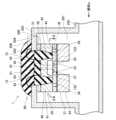
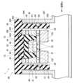
実施例に係るセンサ装置1について図面を参照して説明する。図1は、実施例に係るセンサ装置1の断面図である。図1に示すように、センサ装置1は、液体w(流体の一例)が収容される容器200に取り付けられて使用される。センサ装置1は、センサ部20と、センサ部20を覆うシール部60とを備えている。センサ装置1は、容器200内の液体wの圧力を検出する装置である。圧力検出対象の液体wは例えば水である。A sensor device 1 according to an embodiment will be described with reference to the drawings. FIG. 1 is a cross-sectional view of the sensor device 1 according to an embodiment. As shown in FIG. 1, the sensor device 1 is attached to a
容器200は、液体wが流れる管250に固定されている。管250内を流れる液体wの一部が容器200内に流入し、容器200内に充填される。容器200は、外壁部202と、外壁部202の一部に設けられている開口部203とを備えている。The
外壁部202は、液体wを収容する空間201を画定する。外壁部202は、センサ部20を囲むように配置されている。外壁部202の内面204にセンサ部20が取り付けられている。容器200の開口部203は、外壁部202の上部の中央部に設けられている。開口部203は、容器200の内外を連通させるように開口している。開口部203は外壁部202を貫通している。The
センサ部20は、容器200内(外壁部202の内面204よりも内側)に配置されている。センサ部20は、容器200の開口部203と向かい合う位置に配置されている。センサ部20は、開口部203の周囲の外壁部202に固定されている。センサ部20は、接合材料50を介して外壁部202に固定されている。The
センサ部20は、センサチップ21と、センサチップ21を支持する支持部材40とを備えている。センサチップ21は、例えば、半導体であるSOI(Silicon on Insulator)基板から作製されている。センサチップ21は、ダイヤフラム部22と、ダイヤフラム部22を支持する支持部24と、絶縁膜25とを備えている。センサチップ21は、ダイヤフラム部22が容器200の開口部203と向かい合うように配置されている。The
ダイヤフラム部22は、半導体(例えば、Si)からなる薄い膜状の構成である。ダイヤフラム部22は、センサチップ21の上部の中央部に設けられている。ダイヤフラム部22は、例えば、SOI基板を下面から絶縁膜25までエッチングすることにより作製される。ダイヤフラム部22は、容器200の内の液体wの圧力を受圧する受圧面27を備えている。受圧面27は、ダイヤフラム部22の下面に設けられている。受圧面27は、容器200内を向くように構成されている。容器200内の液体wの圧力が受圧面27に作用する。ダイヤフラム部22は、受圧面27と直交する方向から視たときに略円形状に形成されている。他の実施例では、ダイヤフラム部22が略四角形状に形成されていてもよい。ダイヤフラム部22の形状は限定されるものではない。The
ダイヤフラム部22には複数(本実施例では4個)のピエゾ抵抗部23が設けられている。複数のピエゾ抵抗部23は、ダイヤフラム部22の上部に配置されている。複数のピエゾ抵抗部23は、互いに間隔をあけて配置されている。各ピエゾ抵抗部23は、ダイヤフラム部22を構成する半導体(例えば、Si)にイオン注入をすることにより形成される。ダイヤフラム部22は、容器200内の液体wの圧力を受圧面27が受圧すると上側に撓むように変形する。各ピエゾ抵抗部23は、液体wの圧力によってダイヤフラム部22が変形したときに、それに応じて歪む。各ピエゾ抵抗部23に歪みが生じると、各ピエゾ抵抗部23の抵抗値が変化する。図2に示すように、複数のピエゾ抵抗部23は、それぞれ、複数の配線部28に接続されている。The
複数のピエゾ抵抗部23は、ダイヤフラム部22の応力を検出するためのブリッジ回路(不図示)の一部を構成している。各ピエゾ抵抗部23は、ブリッジ回路における各抵抗要素に相当する。ブリッジ回路に基づいてダイヤフラム部22の応力を検出することによって、ダイヤフラム部22の受圧面27に作用する液体w(容器200内の液体w)の圧力を検出することができる。ブリッジ回路に基づいて応力を検出する方法についてはよく知られているので詳細な説明を省略する。The
図1に示す絶縁膜25は、例えばSiO2膜である。絶縁膜25は、ダイヤフラム部22の下に配置されている。絶縁膜25は、ダイヤフラム部22に配置されている複数のピエゾ抵抗部23よりも受圧面27側(下側)に配置されている。絶縁膜25は、ダイヤフラム部22の受圧面27の全体を覆っている。絶縁膜25は、ダイヤフラム部22から支持部24にわたって延びている。絶縁膜25は、複数のピエゾ抵抗部23と容器200内の液体wとの間に位置している。 The insulating
支持部24は、ダイヤフラム部22の周囲に位置している。支持部24よりも内側にダイヤフラム部22が配置されている。支持部24は、ダイヤフラム部22の外周端部122に固定されている。支持部24は、ダイヤフラム部22の外周端部122を支持している。支持部24は、ダイヤフラム部22と一体的に構成されている。支持部24は、半導体(例えば、Si)から構成されている。上下方向における支持部24の厚みは、ダイヤフラム部22の厚みよりも厚い。支持部24は、厚いブロック状の構成である。支持部24は、ダイヤフラム部22の外周端部122の全周を囲んでいる。支持部24は、ダイヤフラム部22の外周端部122に沿って一周している。The
支持部24には、溝部26が設けられている。溝部26は、支持部24の上面から絶縁膜25に達する位置まで連続して延びている。溝部26は、例えば、SOI基板を絶縁膜25までエッチングすることによって形成される。溝部26は、複数のピエゾ抵抗部23の周りに設けられており、複数のピエゾ抵抗部23の全てを囲んでいる。溝部26は、ダイヤフラム部22の外周端部122よりも外側に設けられている。溝部26は、ダイヤフラム部22の外周端部122の全周を囲んでいる。溝部26は、ダイヤフラム部22の外周端部122に沿って一周している。溝部26は、外周端部122に沿って連続して延びている。溝部26は、ダイヤフラム部22の受圧面27と直交する方向から視たときに略円形状に形成されている。The
図2及び図3に示すように、ダイヤフラム部22と支持部24には複数(本実施例では4個)の配線部28が設けられている。複数の配線部28は、ダイヤフラム部22と支持部24の上部に配置されている。複数の配線部28は、ダイヤフラム部22に設けられている複数のピエゾ抵抗部23に対応する位置に設けられている。各配線部28は、ダイヤフラム部22と支持部24を構成する半導体(例えば、Si)にイオン注入をすることにより形成される。各配線部28の内側の端部281は、各ピエゾ抵抗部23に接続されている。各配線部28は、各ピエゾ抵抗部23からダイヤフラム部22の径方向に延びており、ダイヤフラム部22から支持部24にわたって延びている。各配線部28の外側の端部282は、後述する配線70に電気的に接続されている。外側の端部282は、後述する支持部材40の各開口部43と向かい合っている。2 and 3, the
次に、支持部材40について説明する。図1に示すように、支持部材40は、容器200とセンサチップ21に固定されている。支持部材40は、接合材料50を介して容器200に接着されている。支持部材40の上面が容器200の外壁部202の内面204に固定されている。支持部材40と容器200を接着している接合材料50は、例えばシリコーンである。Next, the
支持部材40は、例えばガラスから構成されている。支持部材40は、例えば陽極接合によりセンサチップ21の上面に接合されている。陽極接合は、ガラスと半導体を接触させた状態で両者の間に電圧を印加することにより両者を接合する方法である。陽極接合については良く知られているので詳細な説明を省略する。The
支持部材40は、支持部41とカバー部42を備えている。支持部41は、カバー部42の周囲に設けられている。支持部41は、容器200の外壁部202とセンサチップ21との間に配置されている。支持部41は、外壁部202とセンサチップ21に固定されている。The
図2に示すように、支持部41には複数(本実施例では4個)の開口部43が設けられている。複数の開口部43は、センサチップ21のダイヤフラム部22を囲むように設けられている。複数の開口部43は、ダイヤフラム部22に設けられている複数のピエゾ抵抗部23に対応する位置に設けられている。各開口部43は、支持部41を上下方向に貫通している。各開口部43は、センサチップ21に設けられている各配線部28の外側の端部282に面する位置に開口している。As shown in FIG. 2, the
図1に示すように、カバー部42は、支持部41の内側に設けられている。カバー部42は、容器200の開口部203に面する位置に配置されている。カバー部42は、容器200の開口部203とセンサチップ21との間に配置されている。カバー部42は、センサチップ21に設けられているダイヤフラム部22を覆っている。カバー部42は、ダイヤフラム部22の上面(受圧面27と反対側の面)を覆っている。カバー部42は、ダイヤフラム部22の上面を覆うことにより空間44を画定している。カバー部42とセンサチップ21との間に空間44が設けられている。カバー部42の下端部は、センサチップ21の上面に例えば陽極接合により固定されている。空間44は、ダイヤフラム部22の上面(受圧面27と反対側の面)に面している。空間44は気密状態にされている。空間44は真空状態であってもよい。As shown in FIG. 1, the
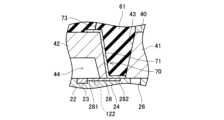
次に、配線70について説明する。図3及び図4に示すように、配線70は、第1配線膜71と、第2配線膜72と、第1配線膜71と第2配線膜72を接続するワイヤ73とを備えている。第1配線膜71、第2配線膜72及びワイヤ73は、金属から構成されている。第1配線膜71は、センサチップ21の支持部24の上面と、支持部材40の開口部43の内面と、カバー部42の上面とに設けられている。支持部24の上面に設けられている第1配線膜71は、配線部28の外側の端部282に接続されている。カバー部42の上面に設けられている第1配線膜71にはワイヤ73の一端部が接続されている。第2配線膜72は、容器200の外壁部202の上面に設けられている。第2配線膜72にはワイヤ73の他端部が接続されている。配線70を通じてピエゾ抵抗部23から信号を取り出すことができる。Next, the
次に、センサ部20を覆うシール部60について説明する。図1に示すように、シール部60は、支持部材40のカバー部42を覆っている。シール部60は、容器200の開口部203を封止している。シール部60は、第1シール部61と、第1シール部61を覆う第2シール部62とを備えている。Next, the sealing
第1シール部61は、支持部材40とセンサチップ21を覆っている。第1シール部61は、支持部材40に設けられている開口部43に充填されている。第1シール部61は、支持部材40のカバー部42の上面と、開口部43の内面とを覆っている。第1シール部61は、第1配線膜71を覆っている(図3参照)。第1シール部61は、例えばシリコーン、変性シリコーン、ウレタン等から構成されている。The
第2シール部62は、第1シール部61と、容器200の外壁部202の上面の一部を覆っている。第2シール部62は、第2配線膜72の一部を覆っている(図4参照)。第2シール部62は、第1シール部61よりも硬い材料から構成されている。第2シール部62は、例えばエポキシ、PVDC等から構成されている。The
第1シール部61と第2シール部62は、容器200の開口部203に充填されており、開口部203の内面を覆っている。第1シール部61と第2シール部62の界面63は、開口部203の内面に接している。第1シール部61と第2シール部62の界面63は、容器200の外壁部202の内面204と外面206の間に位置している。The
以上、実施例に係るセンサ装置1について説明した。上記の説明から明らかなように、センサ装置1は、容器200の外壁部202の内面に固定されているセンサ部20と、センサ部20を覆うように容器200の開口部203を封止しているシール部60とを備えている。センサ部20は、容器200内の液体wの圧力を受圧する受圧面27を備えるダイヤフラム部22と、ダイヤフラム部22の受圧面27と反対側の面と向かい合う空間44を画定するカバー部42とを備えている。The above describes the sensor device 1 according to the embodiment. As is clear from the above description, the sensor device 1 includes a
この構成によれば、液体wの圧力が受圧面27に作用するときにセンサ部20が容器200の外壁部202の内面に押し付けられる。これにより、センサ部20が容器200に強固に固定される。また、容器200の開口部203を通じて水蒸気やガスが通過することをシール部60により抑制することができる。これにより、液体wの圧力を検出するときに水蒸気やガスの影響を抑制することができる。更に、ダイヤフラム部22の受圧面27と反対側においてカバー部42により空間44が画定されるので、液体wの圧力が受圧面27に作用するときに、受圧面27と反対側の面に余分な力が作用しない。以上より、センサ装置1によれば、容器200内の液体wの圧力を精度良く検出することができる。According to this configuration, when the pressure of the liquid w acts on the
シール部60は、センサ部20を覆う第1シール部61と、第1シール部61を覆う第2シール部62とを備えている。第2シール部62は、第1シール部61よりも硬い材料から構成されている。この構成によれば、第1シール部61により主にセンサチップ21の固定と液体wのシールを行うことができる。第2シール部62により主にガスが透過することを抑制することができる。また、外部の力がシール部60を介してセンサ部20に作用するとしても、比較的軟らかい第1シール部61により、センサ部20に作用する力を緩和することができる。The
第1シール部61と第2シール部62の界面63は、容器200の開口部203の内面に接している。第1シール部61と第2シール部62の界面63が仮に外壁部202の内面204よりも内側に位置していると、外部の力が比較的硬い第2シール部62を介してセンサ部20に作用することが考えられる。そうすると、外部の力が緩和されずにセンサ部20に作用することになる。上記の構成によれば、第1シール部61と第2シール部62の界面63が容器200の開口部203の内面に接することにより、外壁部202の内面204よりも内側に第2シール部62が配置されず、第1シール部61のみが配置される。これにより、センサ部20に作用する力を第1シール部61により緩和することができる。The
以上、一実施例について説明したが、具体的な態様は上記実施例に限定されるものではない。以下の説明において、上記の説明における構成と同様の構成については、同一の符号を付して説明を省略する。Although one embodiment has been described above, the specific aspect is not limited to the above embodiment. In the following description, the same components as those described above will be denoted by the same reference numerals and the description will be omitted.
(1)上記の実施例では、センサ部20が容器200内に配置されていたが、この構成に限定されるものではない。他の実施例では、図5に示すように、センサ部20が管250内に配置されていてもよい。管250の外壁部252の内面にセンサ部20が固定されていてもよい。センサ部20は、管250の外壁部252に設けられている開口部253と向か合う位置に配置されている。(1) In the above embodiment, the
(2)上記の実施例では、シール部60が第1シール部61と第2シール部62を備えていたが、この構成に限定されるものではない。他の実施例では、図6に示すように、シール部60が第2シール部62を備えずに、第1シール部61のみを備えている構成であってもよい。更に他の実施例では、シール部60が第1シール部61を備えずに、第2シール部62のみを備えている構成であってもよい(図示省略)。(2) In the above embodiment, the sealing
(3)他の実施例では、図7に示すように、支持部24に複数の溝部26が設けられていてもよい。溝部26の数は特に限定されるものではない。また、溝部26が絶縁膜25を貫通して絶縁膜25の下側まで延びていてもよい。(3) In another embodiment, as shown in FIG. 7, a plurality of
(4)上記の実施例では、絶縁膜25がダイヤフラム部22の受圧面27を覆っている構成であったが、この構成に限定されるものではない。他の実施例では、図8に示すように、ダイヤフラム部22の内部に絶縁膜25が形成されていてもよい。ダイヤフラム部22の受圧面27よりも上側に絶縁膜25が配置されていてもよい。この構成では、絶縁膜25よりも下側に受圧面27が位置している。受圧面27が容器200の内部の液体wに接触している。また、上記の実施例では、支持部24に溝部26が形成されていたが、この構成に限定されるものではない。他の実施例では、図8に示すように、ダイヤフラム部22に溝部26が形成されていてもよい。図8に示す構成によっても、複数のピエゾ抵抗部23を周囲から絶縁すると共にダイヤフラム部22における応力を精度良く検出することができる。(4) In the above embodiment, the insulating
(5)上記の実施例では、ダイヤフラム部22に4個のピエゾ抵抗部23が配置されている構成であったが、この構成に限定されるものではない。他の実施例では、ダイヤフラム部22に例えば2個のピエゾ抵抗部23が配置されている構成であってもよい。(5) In the above embodiment, four
(6)上記の実施例では、流体の一例として液体wを用いていたが、この構成に限定されるものではなく、他の実施例では流体が気体であってもよい。(6) In the above embodiment, liquid w is used as an example of a fluid, but this is not limited to the configuration, and in other embodiments, the fluid may be a gas.
(7)上記の実施例では、支持部材40が接合材料50によって容器200に固定されていたが、この構成に限定されるものではない。他の実施例では、接合材料50に代えて、はんだや低融点ガラスが用いられてもよい。(7) In the above embodiment, the
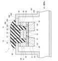
(8)他の実施例では、図9に示すように、シール部60の第1シール部61と第2シール部62の界面63が容器200の開口部203よりも容器200内側に位置していてもよい。即ち、第1シール部61と第2シール部62の界面63が、容器200の外壁部202の内面204よりも内側に位置していてもよい。第1シール部61は、カバー部42及び第1配線膜71(図3参照)を覆っている。第1シール部61と第2シール部62の界面63は、カバー部42の上面に設けられている第1配線膜71よりも上側に位置している。(8) In another embodiment, as shown in FIG. 9, the
この構成によれば、第2シール部62が容器200の外壁部202の内面204よりも内側に位置することによりガスの透過を更に抑制することができる。また、第2シール部62が容器200の外壁部202の内面204よりも内側に位置したとしてもセンサ部20が比較的軟らかい第1シール部61により覆われているので、外部の力が比較的硬い第2シール部62を介してセンサ部20に作用することを抑制することができる。With this configuration, the
なお、センサ部20が管250内に配置されている場合も同様である。即ち、第1シール部61と第2シール部62の界面63が管250の開口部253よりも管250内側に位置していてもよい。The same applies when the
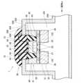
(9)他の実施例では、図10に示すように、シール部60の第1シール部61と第2シール部62の界面63が容器200の開口部203よりも容器200外側に位置していてもよい。即ち、第1シール部61と第2シール部62の界面63が、容器200の外壁部202の外面206よりも外側に位置していてもよい。第1シール部61は第2シール部62により覆われている。第1シール部61と第2シール部62の界面63は、第2シール部62の外面よりも内側に位置している。(9) In another embodiment, as shown in FIG. 10, the
この構成によれば、第1シール部61が容器200の外壁部202の外面206よりも外側に位置することにより、外部の力が第1シール部61により更に緩和される。With this configuration, the
なお、センサ部20が管250内に配置されている場合も同様である。即ち、第1シール部61と第2シール部62の界面63が管250の開口部253よりも管250外側に位置していてもよい。The same applies when the
(10)シール部60の第2シール部62の構成は上記の構成に限定されない。他の実施例では、図11に示すように、シール部60の第2シール部62が、カバー部65と、カバー部65を支持する支持部66とを備えていてもよい。第2シール部62のカバー部65は第1シール部61を覆っている。カバー部65は、容器200の外壁部202に設けられている開口部203と挿入口部207を覆っている。挿入口部207は、開口部203の周囲に設けられている。挿入口部207は、平面視において例えば円形状に構成されている(図示省略)。挿入口部207は、容器200の内外を連通させるように開口している。挿入口部207は外壁部202を貫通している。(10) The configuration of the
第2シール部62の支持部66は、カバー部65の下面(内面)から容器200内に向けて延びている。支持部66は挿入口部207に挿入されている。支持部66は、容器200内に配置されているセンサ部20の周囲に配置されている。支持部66は、センサ部20を囲むように一周している。支持部66は、センサ部20と容器200の外壁部202との間に配置されている。支持部66と外壁部202との間にはシール部材69が配置されている。シール部材69は、容器200内の液体wが外部に漏れないように支持部66と外壁部202との間を封止している。The
(11)他の実施例では、図12に示すように、センサ部20の支持部材40がカバー部42を備えていなくてもよい。(11) In another embodiment, as shown in FIG. 12, the
本明細書または図面に説明した技術要素は、単独で、あるいは各種の組合せによって技術的有用性を発揮するものであり、出願時請求項記載の組合せに限定されるものではない。また、本明細書または図面に例示した技術は複数目的を同時に達成し得るものであり、そのうちの一つの目的を達成すること自体で技術的有用性を持つものである。The technical elements described in this specification or drawings have technical utility either alone or in various combinations, and are not limited to the combinations described in the claims at the time of filing. In addition, the technologies illustrated in this specification or drawings can achieve multiple objectives simultaneously, and achieving one of those objectives is itself technically useful.
1:センサ装置、20:センサ部、21:センサチップ、22:ダイヤフラム部、23:ピエゾ抵抗部、24:支持部、25:絶縁膜、26:溝部、27:受圧面、28:配線部、40:支持部材、41:支持部、42:カバー部、43:開口部、44:空間、60:シール部、61:第1シール部、62:第2シール部、63:界面、70:配線、71:第1配線膜、72:第2配線膜、73:ワイヤ、200:容器、201:空間、202:外壁部、203:開口部、204:内面、206:外面、250:管
1: sensor device, 20: sensor portion, 21: sensor chip, 22: diaphragm portion, 23: piezoresistance portion, 24: support portion, 25: insulating film, 26: groove portion, 27: pressure receiving surface, 28: wiring portion, 40: support member, 41: support portion, 42: cover portion, 43: opening, 44: space, 60: seal portion, 61: first seal portion, 62: second seal portion, 63: interface, 70: wiring, 71: first wiring film, 72: second wiring film, 73: wire, 200: container, 201: space, 202: outer wall portion, 203: opening, 204: inner surface, 206: outer surface, 250: tube
Claims (5)
Translated fromJapanese前記容器又は前記管は、流体を収容する空間を画定する外壁部と、前記外壁部の一部に設けられている開口部と、を備えており、
前記センサ装置は、前記容器内又は前記管内において前記開口部と向かい合う位置に配置されており前記外壁部の内面に固定されているセンサ部と、前記センサ部を覆うように前記開口部を封止しているシール部と、を備えており、
前記センサ部は、前記容器内又は前記管内の流体の圧力を受圧する受圧面を備えるダイヤフラム部を備えており、
前記シール部は、前記センサ部を覆う第1シール部と、前記第1シール部を覆う第2シール部であって前記第1シール部よりも硬い材料から構成されている前記第2シール部とを備えている、センサ装置。 A sensor device for detecting a pressure of a fluid in a container or a pipe,
The container or the pipe includes an outer wall portion defining a space for containing a fluid, and an opening portion provided in a part of the outer wall portion,
The sensor device includes a sensor unit disposed in the container or the pipe at a position facing the opening and fixed to an inner surface of the outer wall portion, and a seal unit that seals the opening so as to cover the sensor unit,
the sensor unit includes a diaphragm unit having a pressure-receiving surface that receives the pressure of the fluid in the container or the pipe,
A sensor device, wherein the sealing portion comprises a first sealing portion that covers the sensor portion, and a second sealing portion that covers the first sealing portion, the second sealing portion being made of a material harder than the first sealing portion.
The sensor device according to claim1 , wherein an interface between the first seal portion and the second seal portion is located on an outer side of the container or the tube than the opening portion.
Priority Applications (1)
| Application Number | Priority Date | Filing Date | Title |
|---|---|---|---|
| JP2020179093AJP7529533B2 (en) | 2020-10-26 | 2020-10-26 | Sensor Device |
Applications Claiming Priority (1)
| Application Number | Priority Date | Filing Date | Title |
|---|---|---|---|
| JP2020179093AJP7529533B2 (en) | 2020-10-26 | 2020-10-26 | Sensor Device |
Publications (2)
| Publication Number | Publication Date |
|---|---|
| JP2022070068A JP2022070068A (en) | 2022-05-12 |
| JP7529533B2true JP7529533B2 (en) | 2024-08-06 |
Family
ID=81534145
Family Applications (1)
| Application Number | Title | Priority Date | Filing Date |
|---|---|---|---|
| JP2020179093AActiveJP7529533B2 (en) | 2020-10-26 | 2020-10-26 | Sensor Device |
Country Status (1)
| Country | Link |
|---|---|
| JP (1) | JP7529533B2 (en) |
Citations (2)
| Publication number | Priority date | Publication date | Assignee | Title |
|---|---|---|---|---|
| US20090108382A1 (en) | 2005-05-03 | 2009-04-30 | Odd Harald Steen Eriksen | Transducer for use in harsh environments |
| US20190041288A1 (en) | 2017-08-02 | 2019-02-07 | Kulite Semiconductor Products, Inc. | High temperature protected wire bonded sensors |
- 2020
- 2020-10-26JPJP2020179093Apatent/JP7529533B2/enactiveActive
Patent Citations (2)
| Publication number | Priority date | Publication date | Assignee | Title |
|---|---|---|---|---|
| US20090108382A1 (en) | 2005-05-03 | 2009-04-30 | Odd Harald Steen Eriksen | Transducer for use in harsh environments |
| US20190041288A1 (en) | 2017-08-02 | 2019-02-07 | Kulite Semiconductor Products, Inc. | High temperature protected wire bonded sensors |
Also Published As
| Publication number | Publication date |
|---|---|
| JP2022070068A (en) | 2022-05-12 |
Similar Documents
| Publication | Publication Date | Title |
|---|---|---|
| US6351996B1 (en) | Hermetic packaging for semiconductor pressure sensors | |
| US8466523B2 (en) | Differential pressure sensor device | |
| US9926188B2 (en) | Sensor unit including a decoupling structure and manufacturing method therefor | |
| JP5206726B2 (en) | Mechanical quantity detection device and manufacturing method thereof | |
| CN109516436B (en) | sensor package | |
| US7563634B2 (en) | Method for mounting semiconductor chips, and corresponding semiconductor chip system | |
| KR20120111989A (en) | Pressure sensor device | |
| KR102588550B1 (en) | Micromechanical pressure sensor device and corresponding manufacturing method | |
| US10254186B2 (en) | Pressure sensor | |
| US20080099861A1 (en) | Sensor device package having thermally compliant die pad | |
| JP7529533B2 (en) | Sensor Device | |
| JP5651670B2 (en) | Pressure detection unit | |
| JP6556620B2 (en) | Pressure sensor | |
| JP2005055313A (en) | Semiconductor pressure sensor device | |
| US4400682A (en) | Pressure sensor | |
| JP7343343B2 (en) | sensor chip | |
| US10994989B2 (en) | Method for producing a microelectromechanical component and wafer system | |
| JP7406947B2 (en) | sensor chip | |
| JP6810680B2 (en) | Pressure sensor | |
| JP4299007B2 (en) | Liquid ring type pressure sensor | |
| JP5718140B2 (en) | Pressure sensor | |
| EP2112487B1 (en) | Method for manufacturing a pressure sensor by applying a cover layer | |
| JP7370819B2 (en) | sensor chip | |
| JP6507596B2 (en) | Semiconductor sensor device | |
| JP2002296136A (en) | Case structure of transducer |
Legal Events
| Date | Code | Title | Description |
|---|---|---|---|
| A621 | Written request for application examination | Free format text:JAPANESE INTERMEDIATE CODE: A621 Effective date:20230719 | |
| A977 | Report on retrieval | Free format text:JAPANESE INTERMEDIATE CODE: A971007 Effective date:20240515 | |
| A131 | Notification of reasons for refusal | Free format text:JAPANESE INTERMEDIATE CODE: A131 Effective date:20240625 | |
| A521 | Request for written amendment filed | Free format text:JAPANESE INTERMEDIATE CODE: A523 Effective date:20240709 | |
| TRDD | Decision of grant or rejection written | ||
| A01 | Written decision to grant a patent or to grant a registration (utility model) | Free format text:JAPANESE INTERMEDIATE CODE: A01 Effective date:20240716 | |
| A61 | First payment of annual fees (during grant procedure) | Free format text:JAPANESE INTERMEDIATE CODE: A61 Effective date:20240725 | |
| R150 | Certificate of patent or registration of utility model | Ref document number:7529533 Country of ref document:JP Free format text:JAPANESE INTERMEDIATE CODE: R150 |