JP7528818B2 - Preform manufacturing method, composite material manufacturing method, and sewing machine for manufacturing preforms - Google Patents
Preform manufacturing method, composite material manufacturing method, and sewing machine for manufacturing preformsDownload PDFInfo
- Publication number
- JP7528818B2 JP7528818B2JP2021027938AJP2021027938AJP7528818B2JP 7528818 B2JP7528818 B2JP 7528818B2JP 2021027938 AJP2021027938 AJP 2021027938AJP 2021027938 AJP2021027938 AJP 2021027938AJP 7528818 B2JP7528818 B2JP 7528818B2
- Authority
- JP
- Japan
- Prior art keywords
- sewing
- adhesive resin
- preform
- resin
- base layer
- Prior art date
- Legal status (The legal status is an assumption and is not a legal conclusion. Google has not performed a legal analysis and makes no representation as to the accuracy of the status listed.)
- Active
Links
- 238000009958sewingMethods0.000titleclaimsdescription229
- 238000004519manufacturing processMethods0.000titleclaimsdescription81
- 239000002131composite materialSubstances0.000titleclaimsdescription42
- 239000000835fiberSubstances0.000claimsdescription168
- 239000004840adhesive resinSubstances0.000claimsdescription155
- 229920006223adhesive resinPolymers0.000claimsdescription155
- 238000000034methodMethods0.000claimsdescription87
- 229920005989resinPolymers0.000claimsdescription75
- 239000011347resinSubstances0.000claimsdescription75
- 238000009966trimmingMethods0.000claimsdescription54
- 230000007246mechanismEffects0.000claimsdescription41
- 238000005304joiningMethods0.000claimsdescription33
- 238000004080punchingMethods0.000claimsdescription33
- 229920005992thermoplastic resinPolymers0.000claimsdescription28
- 238000010438heat treatmentMethods0.000claimsdescription26
- 229920001187thermosetting polymerPolymers0.000claimsdescription23
- 239000011159matrix materialSubstances0.000claimsdescription19
- 239000011162core materialSubstances0.000claimsdescription18
- 238000000465mouldingMethods0.000claimsdescription10
- 238000007493shaping processMethods0.000claimsdescription10
- 230000015572biosynthetic processEffects0.000claimsdescription9
- 238000005520cutting processMethods0.000claimsdescription9
- 230000001678irradiating effectEffects0.000claimsdescription8
- 238000002844meltingMethods0.000claimsdescription4
- 230000008018meltingEffects0.000claimsdescription4
- 239000010410layerSubstances0.000description94
- 230000008569processEffects0.000description42
- 239000012783reinforcing fiberSubstances0.000description21
- 230000006870functionEffects0.000description19
- 239000000463materialSubstances0.000description18
- 238000010586diagramMethods0.000description10
- 238000009728tailored fiber placementMethods0.000description9
- 239000002759woven fabricSubstances0.000description6
- 229920000049Carbon (fiber)Polymers0.000description5
- 239000012790adhesive layerSubstances0.000description5
- 239000004917carbon fiberSubstances0.000description5
- -1polyethylenePolymers0.000description5
- 239000007788liquidSubstances0.000description4
- 229920001225polyester resinPolymers0.000description4
- 239000004645polyester resinSubstances0.000description4
- 238000001721transfer mouldingMethods0.000description4
- 229920003235aromatic polyamidePolymers0.000description3
- 239000000470constituentSubstances0.000description3
- 238000005516engineering processMethods0.000description3
- 239000003822epoxy resinSubstances0.000description3
- 239000004744fabricSubstances0.000description3
- 230000012447hatchingEffects0.000description3
- 229920000647polyepoxidePolymers0.000description3
- 229920000178Acrylic resinPolymers0.000description2
- 239000004925Acrylic resinSubstances0.000description2
- 239000004760aramidSubstances0.000description2
- 238000011074autoclave methodMethods0.000description2
- 239000011230binding agentSubstances0.000description2
- 238000005485electric heatingMethods0.000description2
- 235000021189garnishesNutrition0.000description2
- 239000011521glassSubstances0.000description2
- 238000005470impregnationMethods0.000description2
- 229910010272inorganic materialInorganic materials0.000description2
- 239000011147inorganic materialSubstances0.000description2
- 238000012986modificationMethods0.000description2
- 230000004048modificationEffects0.000description2
- 239000004745nonwoven fabricSubstances0.000description2
- 239000011368organic materialSubstances0.000description2
- 229920000728polyesterPolymers0.000description2
- 238000003825pressingMethods0.000description2
- 239000011359shock absorbing materialSubstances0.000description2
- 239000000126substanceSubstances0.000description2
- 235000013311vegetablesNutrition0.000description2
- 238000005406washingMethods0.000description2
- 239000004953Aliphatic polyamideSubstances0.000description1
- 244000025254Cannabis sativaSpecies0.000description1
- 235000012766Cannabis sativa ssp. sativa var. sativaNutrition0.000description1
- 235000012765Cannabis sativa ssp. sativa var. spontaneaNutrition0.000description1
- 229920000742CottonPolymers0.000description1
- 229920012753Ethylene IonomersPolymers0.000description1
- 229920000271Kevlar®Polymers0.000description1
- 229920000784NomexPolymers0.000description1
- 239000004952PolyamideSubstances0.000description1
- 239000004698PolyethyleneSubstances0.000description1
- 239000004743PolypropyleneSubstances0.000description1
- 229920001494TechnoraPolymers0.000description1
- 229920000561TwaronPolymers0.000description1
- 229920000508VectranPolymers0.000description1
- 239000004979VectranSubstances0.000description1
- 239000006096absorbing agentSubstances0.000description1
- 229920003231aliphatic polyamidePolymers0.000description1
- 125000003118aryl groupChemical group0.000description1
- DQXBYHZEEUGOBF-UHFFFAOYSA-Nbut-3-enoic acid;etheneChemical classC=C.OC(=O)CC=CDQXBYHZEEUGOBF-UHFFFAOYSA-N0.000description1
- 235000009120camoNutrition0.000description1
- 235000005607chanvre indienNutrition0.000description1
- 210000000038chestAnatomy0.000description1
- 239000011248coating agentSubstances0.000description1
- 238000000576coating methodMethods0.000description1
- 229920001577copolymerPolymers0.000description1
- 238000007872degassingMethods0.000description1
- 238000009826distributionMethods0.000description1
- 238000001035dryingMethods0.000description1
- 230000000694effectsEffects0.000description1
- 229920006242ethylene acrylic acid copolymerPolymers0.000description1
- 229920005648ethylene methacrylic acid copolymerPolymers0.000description1
- 239000012530fluidSubstances0.000description1
- 239000003365glass fiberSubstances0.000description1
- LNEPOXFFQSENCJ-UHFFFAOYSA-NhaloperidolChemical compoundC1CC(O)(C=2C=CC(Cl)=CC=2)CCN1CCCC(=O)C1=CC=C(F)C=C1LNEPOXFFQSENCJ-UHFFFAOYSA-N0.000description1
- 239000011487hempSubstances0.000description1
- 239000004761kevlarSubstances0.000description1
- 239000002184metalSubstances0.000description1
- VNWKTOKETHGBQD-UHFFFAOYSA-NmethaneChemical compoundCVNWKTOKETHGBQD-UHFFFAOYSA-N0.000description1
- 239000004763nomexSubstances0.000description1
- 239000005022packaging materialSubstances0.000description1
- 238000005192partitionMethods0.000description1
- 230000002093peripheral effectEffects0.000description1
- 239000012466permeateSubstances0.000description1
- 229920001200poly(ethylene-vinyl acetate)Polymers0.000description1
- 229920002647polyamidePolymers0.000description1
- 229920006122polyamide resinPolymers0.000description1
- 229920002577polybenzoxazolePolymers0.000description1
- 229920000573polyethylenePolymers0.000description1
- 229920013716polyethylene resinPolymers0.000description1
- 229920000098polyolefinPolymers0.000description1
- 229920005672polyolefin resinPolymers0.000description1
- 229920001155polypropylenePolymers0.000description1
- 239000000843powderSubstances0.000description1
- 239000002243precursorSubstances0.000description1
- 239000000047productSubstances0.000description1
- 230000001681protective effectEffects0.000description1
- 210000003660reticulumAnatomy0.000description1
- 230000035807sensationEffects0.000description1
- 229920002050silicone resinPolymers0.000description1
- 239000002356single layerSubstances0.000description1
- 239000007787solidSubstances0.000description1
- 239000007921spraySubstances0.000description1
- 239000004950technoraSubstances0.000description1
- 229920006230thermoplastic polyester resinPolymers0.000description1
- 229920002803thermoplastic polyurethanePolymers0.000description1
- 239000004762twaronSubstances0.000description1
- 229920000785ultra high molecular weight polyethylenePolymers0.000description1
- 238000009281ultraviolet germicidal irradiationMethods0.000description1
- 238000009941weavingMethods0.000description1
- 238000004804windingMethods0.000description1
Images


Landscapes
- Sewing Machines And Sewing (AREA)
- Reinforced Plastic Materials (AREA)
- Casting Or Compression Moulding Of Plastics Or The Like (AREA)
- Moulding By Coating Moulds (AREA)
Description
Translated fromJapanese本発明は、プリフォームの製造方法、複合材の製造方法及びプリフォーム製造用ミシンに関し、更に詳しくは、プリフォームの製造方法、そのプリフォームを用いる複合材の製造方法及びプリフォーム製造用ミシンに関する。The present invention relates to a method for manufacturing a preform, a method for manufacturing a composite material, and a sewing machine for manufacturing a preform, and more specifically, to a method for manufacturing a preform, a method for manufacturing a composite material using the preform, and a sewing machine for manufacturing a preform.
従来、複合材(繊維強化成形体)を製造する方法として、RTM(Resin Transfer Molding)法やVaRTM(Vacuum Assisted Resin Transfer Molding)法等が知られている(例えば、特許文献1等を参照)。これらは、強化繊維を含むプリフォーム(繊維集合体)を成形型のキャビティに配置したうえで、キャビティ内に未硬化樹脂を注入して、プリフォームに未硬化樹脂を含浸させた後、未硬化樹脂を硬化させて複合材を得る方法であり、VaRTM法は、上記のなかでも、未硬化樹脂の含浸を補助するためにキャビティ内を脱気する操作を伴う点でRTM法と異なる。さらに、ミシン(刺繍機)を用いて強化繊維を含む繊維束を基層へ縫着するTFP(Tailored Fiber Placement)技術が知られている(例えば、特許文献2等を参照)。Conventionally, methods for manufacturing composite materials (fiber-reinforced molded bodies) include the RTM (Resin Transfer Molding) method and the Vacuum Assisted Resin Transfer Molding (VaRTM) method (see, for example,
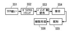
ここで、プリフォームを製造する方法として、例えば、図17に示すように、ミシンを用いて基層(例えば、ガラスクロス等)へ縫製糸を縫い込むことによって繊維束(例えば、炭素繊維束等)を基層へ縫着し(TFP縫い工程SS1)、次に、その繊維束が縫着された基層の不要部を切除し(トリミング工程SS2)、次いで、その不要部が切断された基層、繊維束及び縫製糸に対して接着用樹脂を付与し(接着用樹脂付与工程SS3)、その付与された接着用樹脂を機能させて基層と繊維束を接合して(接合工程SS4)、プリフォームを得る製法が提案されている。
上記の製法によると、接着用樹脂により基層と繊維束が接合されるため、形状安定性に優れたプリフォームが得られる。そのため、RTM法やVaRTM法等において、プリフォームを成形型に容易に配置することができる。
なお、上記提案の製法で得られたプリフォームを成形型のキャビティに配置して賦形し(賦形工程SS5)、キャビティ内に樹脂を充填して固化又は硬化させる(マトリックス形成工程SS6)ことで、複合材が得られる。 Here, as a method for producing a preform, for example, as shown in FIG. 17, a manufacturing method has been proposed in which a sewing machine is used to sew a sewing thread into a base layer (e.g., glass cloth) to sew a fiber bundle (e.g., carbon fiber bundle) to the base layer (TFP sewing step SS1), then unnecessary parts of the base layer to which the fiber bundle is sewn are cut off (trimming step SS2), and then an adhesive resin is applied to the base layer from which the unnecessary parts have been cut off, the fiber bundle and the sewing thread (adhesive resin application step SS3), and the applied adhesive resin is allowed to function to bond the base layer and the fiber bundle (bonding step SS4) to obtain a preform.
According to the above-mentioned manufacturing method, since the base layer and the fiber bundle are bonded by the adhesive resin, a preform having excellent shape stability can be obtained, and therefore, the preform can be easily placed in a mold in the RTM method, VaRTM method, etc.
The preform obtained by the above proposed manufacturing method is placed in a mold cavity and shaped (shaping step SS5), and the cavity is filled with resin and solidified or hardened (matrix formation step SS6) to obtain a composite material.
しかし、上記提案の製法では、TFP縫い工程SS1、トリミング工程SS2、接着用樹脂付与工程SS3及び接合工程SS4の4つの工程をこの順で行ってプリフォームを製造しているため、生産効率が低く、また設備費も高くなる。
さらに、トリミング工程SS2が接着用樹脂付与工程SS3の前に行われるため、高精度のトリミングを行わないと、トリミングの際に縫製糸を切断してしまい繊維束がほつれてしまう恐れがある。 However, in the above proposed manufacturing method, the preform is manufactured by carrying out four steps, namely, the TFP sewing step SS1, the trimming step SS2, the adhesive resin application step SS3, and the joining step SS4, in the stated order, resulting in low production efficiency and high equipment costs.
Furthermore, since the trimming step SS2 is performed before the adhesive resin application step SS3, unless high-precision trimming is performed, there is a risk that the sewing thread will be cut during trimming, causing the fiber bundle to fray.
なお、特許文献2には、TFP技術において、縫製糸及び/又は基層を水溶性物質で形成する技術が記載されている。そのため、特許文献2の技術では、プリフォームを得るために、上記の4つの工程SS1~SS4に加えて、水溶性物質の洗浄工程及び乾燥工程が必要となる。
本発明は、上記現状に鑑みてなされたものであり、形状安定性に優れたプリフォームを効率良く製造することができるプリフォームの製造方法、そのプリフォームを用いる複合材の製造方法、及びそのプリフォームの製造方法に好適に用いられるプリフォーム製造用ミシンを提供することを目的とする。The present invention was made in consideration of the above-mentioned current situation, and aims to provide a method for manufacturing a preform that can efficiently manufacture a preform with excellent shape stability, a method for manufacturing a composite material using the preform, and a sewing machine for manufacturing a preform that is suitable for use in the method for manufacturing the preform.
上記問題を解決するために、請求項1に記載の発明は、基層と、前記基層に縫着された繊維束と、を有して、複合材のコア材となるプリフォームの製造方法であって、前記基層へ縫製糸を縫い込むことによって前記繊維束を前記基層へ縫着する縫着工程と、前記繊維束の縫着ルートの少なくとも一部に接着用樹脂を付与する接着用樹脂付与工程と、前記基層、前記繊維束及び前記縫製糸のうちの2以上を前記接着用樹脂により接合する接合工程と、前記基層の不要部を切除するトリミング工程と、を備え、前記縫製糸の縫い込みを行う際に、前記接着用樹脂の付与を行うことによって、前記縫着工程と、前記接着用樹脂付与工程と、を実質的に同時に行うことを要旨とする。In order to solve the above problem, the invention described in
請求項2に記載の発明は、請求項1記載の発明において、前記縫着が、ミシンを用いた縫製であり、ミシンヘッドが前記接着用樹脂を付与する付与機構を有する要旨とする。The invention described in
請求項3に記載の発明は、請求項2記載の発明において、前記ミシンヘッドは、縫い針と、前記縫い針の軸回りに回転可能に設けられて、前記繊維束が巻かれたボビンを有する回転体と、を備え、前記付与機構は、前記回転体に設けられるロータリージョイントと、前記ロータリージョイントに形成された前記接着用樹脂の供給通路に接続されるノズルと、を備えることを要旨とする。The invention described in
請求項4に記載の発明は、請求項1乃至3のいずれか一項に記載の発明において、前記トリミング工程は、打抜型を用いて前記基層の不要部を切除する工程であり、前記打抜型が、打ち抜きの際に、前記接着用樹脂を機能させることによって、前記トリミング工程と、前記接合工程と、を実質的に同時に行うことを要旨とする。The invention described in
請求項5に記載の発明は、請求項4に記載の発明において、前記接着用樹脂が、熱可塑性樹脂及び/又は熱硬化性樹脂であり、前記打抜型は、加熱部を有し、前記加熱部の加熱により、前記熱可塑性樹脂を溶融、及び/又は、前記熱硬化性樹脂を硬化、させて前記接着用樹脂を機能させることを要旨とする。The invention described in
請求項6に記載の発明は、請求項1乃至3のいずれか一項に記載の発明において、前記接着用樹脂が、光硬化性樹脂であり、前記接合工程は、前記トリミング工程前に、前記光硬化性樹脂に対して光照射を行う工程であることを要旨とする。The invention described in claim 6 is the invention described in any one of
上記問題を解決するために、請求項7に記載の発明は、複合材の製造方法であって、請求項1乃至6のうちのいずれかに記載のプリフォームの製造方法により得られたプリフォームを、成形型内に配置して賦形する賦形工程と、前記成形型内に、熱硬化性樹脂を充填して硬化、又は、熱可塑性樹脂を充填して固化、するマトリックス形成工程と、を備えることを要旨とする。In order to solve the above problems, the invention described in
上記問題を解決するために、請求項8に記載の発明は、基層と、前記基層に縫着された繊維束と、を有して、複合材のコア材となるプリフォームを製造するためのミシンであって、ミシンヘッドが接着用樹脂を付与する付与機構を有することを要旨とする。In order to solve the above problem, the invention described in
本発明のプリフォームの製造方法によると、基層へ縫製糸を縫い込むことによって繊維束を基層へ縫着する縫着工程と、繊維束の縫着ルートの少なくとも一部に接着用樹脂を付与する接着用樹脂付与工程と、基層、繊維束及び縫製糸のうちの2以上を接着用樹脂により接合する接合工程と、基層の不要部を切除するトリミング工程と、を備える。そして、縫製糸の縫い込みを行う際に、接着用樹脂の付与を行うことによって、縫着工程と、接着用樹脂付与工程と、を実質的に同時に行う。これにより、形状安定性に優れたプリフォームを効率良く製造でき、設備費を低減することができる。さらに、トリミング工程の前に接着用樹脂付与工程が行われるため、トリミングの際に縫製糸が切断されても、接着用樹脂の接合により繊維束がほつれてしまうことが抑制される。そのため、トリミングの精度に余裕ができてトリミングを容易に行うことができる。According to the preform manufacturing method of the present invention, the method includes a sewing step of sewing a fiber bundle to a base layer by sewing a sewing thread into the base layer, an adhesive resin application step of applying an adhesive resin to at least a part of the sewing route of the fiber bundle, a joining step of joining two or more of the base layer, the fiber bundle, and the sewing thread with an adhesive resin, and a trimming step of cutting off unnecessary parts of the base layer. The sewing step and the adhesive resin application step are performed substantially simultaneously by applying an adhesive resin when sewing the sewing thread. This allows efficient manufacturing of a preform with excellent shape stability and reduces equipment costs. Furthermore, since the adhesive resin application step is performed before the trimming step, even if the sewing thread is cut during trimming, the fiber bundle is prevented from fraying due to the bonding of the adhesive resin. Therefore, trimming can be performed easily with a margin of accuracy.
また、前記縫着が、ミシンを用いた縫製であり、ミシンヘッドが前記接着用樹脂を付与する付与機構を有する場合は、繊維束の縫着ルートに対して接着用樹脂を正確に付与することができる。In addition, if the sewing is performed using a sewing machine and the sewing machine head has an application mechanism for applying the adhesive resin, the adhesive resin can be applied accurately to the sewing route of the fiber bundle.
また、前記ミシンヘッドが、縫い針と、前記縫い針の軸回りに回転可能に設けられて、前記繊維束が巻かれたボビンを有する回転体と、を備え、前記付与機構が、前記回転体に設けられるロータリージョイントと、前記ロータリージョイントに形成された前記接着用樹脂の供給通路に接続されるノズルと、を備える場合は、回転体の回転制御により、ボビンから繰り出される繊維束が縫着ルートに沿って供給されるとともに、接着用樹脂の供給用配管が絡まることなく、ロータリージョイントの供給通路を介して接着用樹脂がノズルに供給されて縫着ルートに付与される。In addition, when the sewing machine head includes a sewing needle and a rotating body that is rotatable around the axis of the sewing needle and has a bobbin around which the fiber bundle is wound, and the application mechanism includes a rotary joint that is provided on the rotating body and a nozzle that is connected to a supply passage for the adhesive resin formed in the rotary joint, the fiber bundle that is unwound from the bobbin is supplied along the sewing route by controlling the rotation of the rotating body, and the adhesive resin is supplied to the nozzle via the supply passage of the rotary joint and applied to the sewing route without the adhesive resin supply piping becoming tangled.
また、前記トリミング工程が、打抜型を用いて前記基層の不要部を切除する工程であり、前記打抜型が、打ち抜きの際に、前記接着用樹脂を機能させることによって、前記トリミング工程と、前記接合工程と、を実質的に同時に行う場合は、プリフォームを更に効率良く製造することができる。In addition, if the trimming step is a step of cutting out unnecessary portions of the base layer using a punching die, and the punching die causes the adhesive resin to function during punching, thereby performing the trimming step and the joining step substantially simultaneously, the preform can be manufactured even more efficiently.
また、前記接着用樹脂が、熱可塑性樹脂及び/又は熱硬化性樹脂であり、前記打抜型が、加熱部を有し、前記加熱部の加熱により、前記熱可塑性樹脂を溶融、及び/又は、前記熱硬化性樹脂を硬化、させて前記接着用樹脂を機能させる場合は、打抜型の加熱部により接着用樹脂を効果的に機能させることができる。In addition, when the adhesive resin is a thermoplastic resin and/or a thermosetting resin, and the punching die has a heating section, and the adhesive resin is made to function by melting the thermoplastic resin and/or curing the thermosetting resin through heating by the heating section, the adhesive resin can be made to function effectively by the heating section of the punching die.
また、前記接着用樹脂が、光硬化性樹脂であり、前記接合工程が、前記トリミング工程前に、前記光硬化性樹脂に対して光照射を行う工程である場合は、トリミング工程の前に、光照射により接着用樹脂を効果的に機能させることができる。In addition, if the adhesive resin is a photocurable resin and the joining process is a process of irradiating the photocurable resin with light before the trimming process, the adhesive resin can be made to function effectively by irradiating it with light before the trimming process.
本発明の複合材の製造方法によると、上記のプリフォームの製造方法により得られたプリフォームを、成形型内に配置して賦形する賦形工程と、前記成形型内に、熱硬化性樹脂を充填して硬化、又は、熱可塑性樹脂を充填して固化、するマトリックス形成工程と、を備える。これにより、形状安定性に優れたプリフォームを成形型内に容易に配置することができる。よって、複合材を効率良く製造することができる。The composite material manufacturing method of the present invention includes a shaping step in which the preform obtained by the above preform manufacturing method is placed in a mold and shaped, and a matrix formation step in which the mold is filled with a thermosetting resin and hardened, or filled with a thermoplastic resin and solidified. This makes it possible to easily place a preform with excellent shape stability in the mold. This allows the composite material to be manufactured efficiently.
本発明のプリフォーム製造用ミシンによると、ミシンヘッドが接着用樹脂を付与する付与機構を有する。これにより、縫製糸の縫い込みを行う際に、付与機構により接着用樹脂の付与を行うことができる。よって、形状安定性に優れたプリフォームを効率良く製造でき、設備費を低減することができる。According to the sewing machine for manufacturing preforms of the present invention, the sewing machine head has an application mechanism for applying adhesive resin. This allows the application mechanism to apply adhesive resin when sewing the sewing thread. This makes it possible to efficiently manufacture preforms with excellent shape stability and reduce equipment costs.
本発明について、本発明による典型的な実施形態の非限定的な例を挙げ、言及された複数の図面を参照しつつ以下の詳細な記述にて更に説明するが、同様の参照符号は図面のいくつかの図を通して同様の部品を示す。
ここで示される事項は例示的なものおよび本発明の実施形態を例示的に説明するためのものであり、本発明の原理と概念的な特徴とを最も有効に且つ難なく理解できる説明であると思われるものを提供する目的で述べたものである。この点で、本発明の根本的な理解のために必要である程度以上に本発明の構造的な詳細を示すことを意図してはおらず、図面と合わせた説明によって本発明の幾つかの形態が実際にどのように具現化されるかを当業者に明らかにするものである。The matters set forth herein are illustrative and are intended to provide an illustrative description of the embodiments of the present invention, with the objective of providing what is believed to be the most effective and easily understood explanation of the principles and conceptual features of the present invention. In this regard, it is not intended to provide structural details of the present invention beyond the extent necessary for a fundamental understanding of the present invention, but rather to make clear to those skilled in the art, through the description in conjunction with the drawings, how some forms of the present invention may be embodied in practice.
<プリフォームの製造方法>
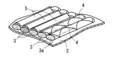
本実施形態に係るプリフォームの製造方法は、例えば、図1~図3及び図5に示すように、基層2と、基層2に縫着された繊維束3と、を有して、複合材7のコア材となるプリフォーム1の製造方法であって、基層2へ縫製糸4を縫い込むことによって繊維束3を基層2へ縫着する縫着工程S1と、繊維束3の縫着ルートの少なくとも一部に接着用樹脂5を付与する接着用樹脂付与工程S2と、基層2、繊維束3及び縫製糸4のうちの2以上を接着用樹脂5により接合する接合工程S3と、基層2の不要部2aを切除するトリミング工程S4と、を備える。そして、縫製糸4の縫い込みを行う際に、接着用樹脂5の付与を行うことによって、縫着工程S1と、接着用樹脂付与工程S2と、を実質的に同時に行う。<Preform manufacturing method>
1 to 3 and 5, the method for manufacturing a preform according to the present embodiment is a method for manufacturing a
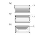
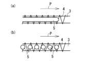
上記「縫着工程S1」の縫着形態は限定されない。この縫着工程S1では、例えば、基層2に対して繊維束3を複列に平面状に並べて配置して縫着することができる。より具体的には、所定面を埋めるように複数本の繊維束3を引き揃えて縫着することができる(図6(a)参照)。さらに、繊維束3を折りたたんで所定面を埋めるように縫着することができる。例えば、1本の繊維束3を蛇腹状に折り畳んで配置して縫着したり(図6(b)参照)、螺旋状(円螺旋、多角形螺旋等)に巻回することによって折り畳んで配置して縫着したり(図6(c)参照)することができる。The sewing form of the above-mentioned "sewing step S1" is not limited. In this sewing step S1, for example, the
縫着工程S1では、例えば、基層2に対して1層となるように繊維束3を敷き詰めて縫着してもよいし(図2参照)、2層以上となるように複層に繊維束3を敷き詰めて縫着してもよい(図7(a)参照)。さらに、基層2の表裏に繊維束3を各々敷き詰めて縫着してもよい(図7(b)参照)。また、2層以上に敷き詰めて縫着する場合や、表裏に敷き詰めて縫着する場合には、一層を構成する繊維束3の配列方向と、隣接される他層を構成する繊維束3の配列方向と、は平行に配置してもよいが、配列方向が異なるように、交差させて配置できる。この場合、交差角度は90度以下(0度<θ≦90度)にすることができる。In the sewing step S1, for example, the
なお、上記の各種の縫着態様は、1種のみを用いてよく2種以上を併用してもよい。また、当然ながら、上記以外の縫着形態を利用できる。特に、複合材7の狙いの強度分布等に応じて、2種以上の縫着態様を併用して、基層2に対して粗密の差をつけて繊維束3を縫着することが好ましい。
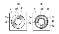
また、縫着工程S1では、通常、基層2に繊維束3が縫着された縫着領域R1と繊維束3が縫着されない非縫着領域R2とが形成される(図8(a)参照)。この非縫着領域R2の少なくとも一部を含む基層2の部分は、後述のトリミング工程S4で不要部2aとして切除される。 The above-mentioned various sewing modes may be used alone or in combination of two or more. Needless to say, sewing modes other than those mentioned above may also be used. In particular, it is preferable to use two or more sewing modes in combination to sew the
In the sewing step S1, a sewn region R1 where the
縫着工程S1では、例えば、ミシン(刺繍機)11を用いて基層2へ縫製糸4を縫い込むことができる。このミシン11としては、例えば、図11及び図12に示すように、ミシンヘッド12が、縫い針15と、縫い針15の軸回りに回転可能に設けられて、繊維束3が巻かれたボビン16を有する回転体17と、を備える形態を採用できる。より具体的に、ミシンヘッド12と、ミシンヘッド12の下方で平面方向に移動可能に設けられて基層2を保持する保持枠13と、を備え、保持枠13の移動制御及び回転体17の回転制御によって、繊維束3の縫着ルートに沿ってボビン16から繰り出される繊維束3を縫い針15で基層2に縫着する形態を採用できる。In the sewing step S1, for example, a sewing machine (embroidery machine) 11 can be used to sew the
上記「接着用樹脂付与工程S2」の付与形態は限定されない。この付与工程S2では、例えば、繊維束3の縫着ルート(縫着領域R1)の全部に接着用樹脂5を付与してもよいし、繊維束3の縫着ルートの一部に接着用樹脂5を付与してもよい。これらの形態は、プリフォーム1の形状安定性及び強度等の観点から適宜選択される。
より具体的に、図8(a)に示すように、繊維束3の縫着ルート(図中に45度ハッチングで示す領域R1)の全域に接着用樹脂5を付与してもよいし、図8(b)に示すように、繊維束3の縫着ルート(図中に45度ハッチングで示す領域R1)の一部(図中に135度ハッチングで示す領域R1’)に接着用樹脂5を付与してもよい。
さらに、繊維束3の縫着ルートの一部に接着用樹脂5を付与する場合には、例えば、その一部は、トリミング工程S4で切除される基層2の不要部2aに隣接する部位を含むことができる。これにより、トリミングの際に縫製糸4が切断されても、接着用樹脂5の接合により繊維束3がほつれてしまうことが抑制される。 The application form of the above-mentioned "adhesive resin application step S2" is not limited. In this application step S2, for example, the
More specifically, as shown in FIG. 8( a ), the
Furthermore, when the
接着用樹脂付与工程S2では、例えば、繊維束3の縫着ルートに沿って基層2上に配置された縫着後又は縫着前の繊維束3上に接着用樹脂5を付与することができる(図1参照)。この場合、例えば、繊維束3の側縁からはみ出ないように接着用樹脂5を付与してもよいし、はみ出るように接着用樹脂5を付与してもよい。In the adhesive resin application step S2, for example,
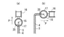
接着用樹脂付与工程S2では、例えば、図13に示すように、ミシンヘッド12が接着用樹脂5を付与する付与機構23を有するミシン11を採用できる。この付与機構23は、例えば、回転体17に設けられるロータリージョイント(回転継手)24と、ロータリージョイント24に形成された接着用樹脂5の供給通路27に接続されるノズル25と、を備えることができる。これにより、回転体17の回転時に供給用配管29が絡まることなく、繊維束3の縫着ルートに対して接着用樹脂5を正確に付与することができる。
また、付与機構23としては、例えば、チュービング式、空圧式、容量計量式、ジェット式、プランジャー式のディスペンサなどを採用できる。 13, for example, a
As the
接着用樹脂5の形態は限定されない。接着用樹脂5としては、例えば、熱可塑性樹脂、熱硬化性樹脂、光硬化性樹脂(UV硬化性樹脂を含む)などを採用できる。これらのうち、複合材7のマトリックス樹脂9に対する接着用樹脂5(接着層5’)の異物感の低減性等の観点から、接着用樹脂5として複合材7のマトリックス樹脂9と同種の樹脂を採用することが好ましい。
熱可塑性樹脂としては、例えば、ポリエチレン、ポリプロピレン、エチレン・プロピレン共重合体などのポリオレフィンの酸変性物、エチレン・酢酸ビニル共重合体の酸変性物、エチレン・アクリル酸共重合体、エチレン・メタクリル酸共重合体、アイオノマーなどを用いることができる。これらは単独で、又は複数種を混合して採用できる。さらに、硬化性樹脂としては、例えば、エポキシ系樹脂、アクリル系樹脂、シリコーン樹脂などを用いることができる。これらは単独で、又は複数種を混合して採用できる。
また、接着用樹脂5の含有割合は、例えば、プリフォーム1をなす全構成繊維100質量%に対して1~5%とすることができる。さらに、接着用樹脂5は、例えば、液状で付与されてもよいし、粉体等の固形で付与されてもよい。さらに、接着用樹脂5は、例えば、繊維束3の縫着ルートに沿ってライン状に付与されてもよいし(図9(a)参照)、ドット状に付与されてもよい(図9(b)参照)。さらに、接着用樹脂5の付与形態としては、例えば、ノズル、スプレー、ロールなどによる塗布や散布を採用できる。 The form of the
Examples of the thermoplastic resin include acid-modified polyolefins such as polyethylene, polypropylene, and ethylene-propylene copolymers, acid-modified ethylene-vinyl acetate copolymers, ethylene-acrylic acid copolymers, ethylene-methacrylic acid copolymers, and ionomers. These may be used alone or in combination. Examples of the curable resin include epoxy resins, acrylic resins, and silicone resins. These may be used alone or in combination.
The content of the
上記「接合工程S3」の接合形態は限定されない。この接合工程S3では、例えば、加熱により熱可塑性樹脂(接着用樹脂5)を溶融して機能させたり、加熱により熱硬化性樹脂(接着用樹脂5)を硬化させて機能させたり、光照射により光硬化性樹脂(接着用樹脂5)を硬化させて機能させたりすることができる。このように接着用樹脂5を機能させることで、基層2、繊維束3及び縫製糸4のうちの2以上が接合されるため、プリフォーム1の形状安定性(即ち、取扱性)が高められる。The bonding form of the above-mentioned "bonding step S3" is not limited. In this bonding step S3, for example, the thermoplastic resin (adhesive resin 5) can be melted by heating to function, the thermosetting resin (adhesive resin 5) can be hardened by heating to function, or the photosetting resin (adhesive resin 5) can be hardened by light irradiation to function. By making the
接着用樹脂5が熱可塑性樹脂又は熱硬化性樹脂である場合、接合工程S3は、例えば、トリミング工程S4前に行われてもよいが、生産効率等の観点から、後述するように、トリミング工程S4と実質的に同時に行うことが好ましい。
また、接着用樹脂5が光硬化性樹脂である場合、接合工程S3は、例えば、トリミング工程S4前に、光硬化性樹脂に対して光照射を行って光硬化性樹脂を機能させることができる。特に、生産効率等の観点から、縫着工程S1と接着用樹脂付与工程S2と接合工程S3とを実質的に同時に行うことが好ましい。 When the
Furthermore, when the
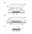
上記「トリミング工程S4」のトリミング形態は限定されない。このトリミング工程S4では、例えば、ハサミやレーザーにより基層2の不要部2aを切除してもよいが、生産効率等の観点から、打抜型41を用いて基層2の不要部2aを切除することが好ましい。この場合、例えば、図3に示すように、打抜型41が、打ち抜きの際に、接着用樹脂5を機能させることができる。これにより、トリミング工程S4と、接合工程S3と、を実質的に同時に行うことができる。
より具体的に、接着用樹脂5が、熱可塑性樹脂及び/又は熱硬化性樹脂であり、打抜型41は、加熱部43を有し、加熱部43の加熱により、熱可塑性樹脂を溶融、及び/又は、熱硬化性樹脂を硬化、させて接着用樹脂5を機能させることができる。この場合、例えば、加熱部43と熱可塑性樹脂及び/又は熱硬化性樹脂とが接触することで(好ましくは、加熱部43が熱可塑性樹脂及び/又は熱硬化性樹脂を押圧することで)、接着用樹脂5を効果的に機能させることができる。
また、加熱部43としては、電熱線を用いる電気ヒータや熱流体を用いる機構などを採用できる。 The trimming form of the above-mentioned "trimming step S4" is not limited. In this trimming step S4, the
More specifically, the
As the
上記「プリフォーム(繊維集合体)1」は、例えば、図3(c)に示すように、基層2と、基層2に縫着された繊維束3と、を有する。このプリフォームは、例えば、基層2、繊維束3及び縫製糸4のうちの2以上を接合する接着層5’を有することができる。この接着層5’は、上記の接着用樹脂5により形成される層である。The above-mentioned "preform (fiber aggregate) 1" has a
基層2として、不織布、織物及び編物等のうちの1種又は2種以上を採用できる。例えば、繊維束3が織物製の基層2に縫着された形態や、繊維束3が不織布製の基層2に縫着された形態が挙げられる。さらに、繊維束3を縫着する縫製糸4はどのような繊維を用いてもよい。即ち、後述する強化繊維と同様の繊維を用いてもよく、強化繊維以外の他の繊維を用いてもよい。さらに、縫製糸4のテンションにより、繊維束3の拘束の程度を自在に制御できる。従って、基層2に対して繊維束3を強固に固定しながら、繊維束3の可動性(基層2に対する可動性、及び/又は、繊維束3同士の間の可動性)を、繊維束3を製織してなる織布等と比較してより多く確保できる。その結果、例えば、プリフォーム1の柔軟性を高く保つことができる。As the
基層2は、織物であることが好ましい。これは、繊維束3を縫着し易いこと、縫着した際の縫製糸4に対する拘束が高いこと、基層2として柔軟性に優れること、更には、マトリックス樹脂(未固化物)を含浸させ易いこと等の利点を有するためである。織物を構成する繊維には、どのような繊維を用いてもよい。即ち、後述する強化繊維と同様の繊維を用いてもよく、強化繊維以外の他の繊維を用いてもよい。The
繊維束3は、連続繊維を束ねた形態であり、連続繊維の一部又は全部として強化繊維が含まれる。即ち、繊維束3は、強化繊維のみから形成されてもよいし、強化繊維以外の他の繊維を含んでもよい。The
強化繊維は、通常の繊維に比べて機械的強度に優れる繊維であり、例えば、JIS L1015による引張強さにおいて7cN/dtex以上(通常50cN/dtex)を有する繊維が好ましい。
また、強化繊維は、無機材料からなる繊維であってもよく、有機材料からなる繊維であってもよく、これらを併用した繊維であってもよい。無機材料繊維としては、炭素繊維(PAN系炭素繊維、ピッチ系炭素繊維)、ガラス繊維、金属繊維などが挙げられる。これらは1種のみを用いてもよく2種以上を併用してもよい。また、有機材料繊維としては、芳香族ポリアミド樹脂繊維(パラ型アラミド:商品名「ケブラー」、商品名「トワロン」、商品名「テクノーラ」等、メタ型アラミド:商品名「ノーメックス」、商品名「コーネックス」等)、ポリベンズアゾール樹脂繊維(ポリパラフェニレンベンゾビスオキサゾール繊維、商品名「ザイロン」等)、芳香族ポリエステル樹脂繊維(商品名「ベクトラン」等)、高強度ポリエチレン樹脂繊維(商品名「ダイニーマ」)などが挙げられる。これらは1種のみを用いてもよく2種以上を併用してもよい。 The reinforcing fibers are fibers that have superior mechanical strength compared to ordinary fibers, and for example, fibers having a tensile strength of 7 cN/dtex or more (usually 50 cN/dtex) according to JIS L1015 are preferred.
The reinforcing fibers may be fibers made of inorganic materials, fibers made of organic materials, or fibers made of a combination of these. Examples of inorganic material fibers include carbon fibers (PAN-based carbon fibers, pitch-based carbon fibers), glass fibers, metal fibers, etc. These may be used alone or in combination of two or more types. Examples of organic material fibers include aromatic polyamide resin fibers (para-aramid: trade name "Kevlar", trade name "Twaron", trade name "Technora", etc., meta-aramid: trade name "Nomex", trade name "Conex", etc.), polybenzazole resin fibers (polyparaphenylene benzobisoxazole fibers, trade name "Zylon", etc.), aromatic polyester resin fibers (trade name "Vectran", etc.), high-strength polyethylene resin fibers (trade name "Dyneema"), etc. These may be used alone or in combination of two or more types.
強化繊維の繊維形態は限定されず、スパンヤーンであってもよく、フィラメントヤーンであってもよく、これらの併用形態であってもよいが、これらのなかでは、フィラメントヤーンであることが好ましい。更に、強化繊維は、モノフィラメントであってもよく、マルチフィラメントであってもよく、これらを併用してもよい。The fiber form of the reinforcing fiber is not limited, and may be spun yarn, filament yarn, or a combination of these, but among these, filament yarn is preferable. Furthermore, the reinforcing fiber may be monofilament, multifilament, or a combination of these.
1本の繊維束3を構成する連続繊維3aの本数は限定されず、例えば、3000本以上とすることができる。繊維束3を構成する連続繊維3aの本数が3000本以上であることにより、柔軟でありながらプリフォーム1として優れた強度を発揮させることができる。この本数は限定されないが、例えば、3000本以上100000本以下とすることができ、更に5000本以上70000本以下とすることができ、更に7000本以上50000本以下とすることができ、更に10000本以上30000本以下とすることができる。The number of
また、繊維束3を扱う際の作業性を考慮した場合、1本の繊維束3を構成する連続繊維3aの本数が多い繊維束(太束)3を用いることができる。この場合、1本の繊維束3を構成する連続繊維3aの本数は、例えば、30000本以上とすることができ、更に40000本以上とすることができ、更に60000本以上とすることができる。一方、1本の繊維束3を構成する連続繊維3aの本数は、例えば、1500000本以下、更に1000000本以下とすることができる。In addition, when considering the workability when handling the
プリフォーム1は、構成繊維の全てが強化繊維からなってもよいし、部分的に強化繊維を含んでもよい。強化繊維による構成率は限定されないが、プリフォーム1をなす全構成繊維100質量%に対し、強化繊維の含有割合は50質量%以上(100質量%でもよい)にすることができ、75質量%以上にすることができ、90質量%以上にすることができる。即ち、プリフォーム1が、強化繊維以外の他繊維を含む場合、構成繊維全体を100質量%とした場合に、他繊維は50質量%未満(1質量%以上)にすることができ、25質量%未満にすることができ、10質量%未満にすることができる。
強化繊維以外の他繊維の構成材料は限定されず、上述した強化繊維以外の繊維を利用できる。具体的には、各種の樹脂繊維及び植物性繊維等を用いることができ、このうち樹脂繊維を構成する樹脂として、ポリアミド(脂肪族ポリアミド等)、ポリエステル(芳香族ジカルボン酸由来の構成単位を有するポリエステル等)等を利用できる。また、植物繊維としては、綿繊維及び麻繊維等を用いることができる。
また、他繊維の繊維形態も限定されず、スパンヤーンであってもよく、フィラメントヤーンであってもよく、これらの併用形態であってもよい。 The material of the fibers other than the reinforcing fibers is not limited, and fibers other than the reinforcing fibers described above can be used. Specifically, various resin fibers and vegetable fibers can be used, and among these, polyamides (aliphatic polyamides, etc.), polyesters (polyesters having structural units derived from aromatic dicarboxylic acids, etc.) can be used as the resins constituting the resin fibers. In addition, cotton fibers and hemp fibers can be used as the vegetable fibers.
The fiber form of the other fibers is not limited either, and may be spun yarn, filament yarn, or a combination of these.
プリフォーム1は、複合材(繊維強化成形体)7のコア材(芯材)となる。このプリフォーム1を用いる複合材7の製法は限定されず、例えば、RTM(Resin Transfer Molding)法、VaRTM(Vacuum Assisted Resin Transfer Molding)法、オートクレーブ法、熱プレス法等が挙げられる。
RTM法及びVaRTM法は、プリフォーム1を成形型45内に配置して賦形し、成形型45内に熱硬化性樹脂を充填して硬化又は熱可塑性樹脂を充填して固化する方法である。また、VaRTM法は、プリフォーム1内への樹脂含浸を補助するためにキャビティ内を減圧する減圧工程を備える点でRTM法と異なる。また、オートクレーブ法は、熱硬化性樹脂を含浸したプリフォーム1をオートクレーブ内で加熱硬化する方法である。さらに、熱プレス法は、熱硬化性樹脂を含浸したプリフォーム1を熱プレスにより加熱加圧硬化させる方法である。 The
The RTM method and the VaRTM method are methods in which the
上記「複合材(繊維強化成形体)7」は、コア材8と、コア材8を埋設するマトリックス樹脂9と、を有する(図10参照)。この複合材7において、マトリックス樹脂9は、コア材8を埋設している樹脂である。より具体的には、コア材8の内部に行きわたるように含浸されて固定(硬化性樹脂である場合には硬化、熱可塑性樹脂である場合には固化)された樹脂である。このマトリックス樹脂9の含浸方法及び固定方法は、従来公知の各種方法を利用できる。The above-mentioned "composite material (fiber-reinforced molding) 7" has a
コア材8は、基層2と、基層2の一面に縫着された繊維束3とで構成された1層の片面プリフォーム1のみを配置してもよいし(図10(a)参照)、片面プリフォーム1を基層2同士が対向されるように向かい合わせて配置してもよい(図10(b)参照)。このように片面プリフォーム1を2層用いる場合には、基層2同士を対面させることにより、複合材7の耐衝撃性を効率的に向上させることができる。The
マトリックス樹脂9の種類は限定されず、種々の樹脂を利用できる。即ち、硬化性樹脂を用いてもよく、熱可塑性樹脂を用いてもよく、これらを併用してもよい。硬化性樹脂としては、エポキシ樹脂、ポリエステル樹脂(硬化性ポリエステル樹脂)、ウレタン樹脂等が挙げられる。一方、熱可塑性樹脂としては、ポリオレフィン樹脂、アクリル樹脂、ポリエステル樹脂(熱可塑性ポリエステル樹脂)、ポリアミド樹脂等が挙げられる。The type of
複合材7の用途は特に限定されないが、例えば、自動車、鉄道車両、船舶及び飛行機等の外装材、内装材、構造材(ボディシェル、車体、航空機用胴体)及び衝撃吸収材等として用いることができる。これらのうち自動車用品としては、自動車用外装材、自動車用内装材、自動車用構造材、自動車用衝撃吸収材、エンジンルーム内部品等が挙げられる。
具体的には、バンパー、スポイラー、カウリング、フロントグリル、ガーニッシュ、ボンネット、トランクリッド、カウルルーバー、フェンダーパネル、ロッカーモール、ドアパネル、ルーフパネル、インストルメントパネル、センタークラスター、ドアトリム、クオータートリム、ルーフライニング、ピラーガーニッシュ、デッキトリム、トノボード、パッケージトレイ、ダッシュボード、コンソールボックス、キッキングプレート、スイッチベース、シートバックボード、シートフレーム、アームレスト、サンバイザ、インテークマニホールド、エンジンヘッドカバー、エンジンアンダーカバー、オイルフィルターハウジング、車載用電子部品(ECU、TVモニター等)のハウジング、エアフィルターボックス、ラッシュボックス等のエネルギー吸収体、フロントエンドモジュール等のボディシェル構成部品などが挙げられる。 The use of the
Specific examples include bumpers, spoilers, cowlings, front grilles, garnishes, bonnets, trunk lids, cowl louvers, fender panels, rocker moldings, door panels, roof panels, instrument panels, center clusters, door trims, quarter trims, roof linings, pillar garnishes, deck trims, tonneau boards, package trays, dashboards, console boxes, kicking plates, switch bases, seat backboards, seat frames, armrests, sun visors, intake manifolds, engine head covers, engine under covers, oil filter housings, housings for in-vehicle electronic components (ECUs, TV monitors, etc.), energy absorbers such as air filter boxes and rush boxes, and body shell components such as front end modules.
更に、例えば、建築物及び家具等の内装材、外装材及び構造材等が挙げられる。即ち、ドア表装材、ドア構造材、各種家具(机、椅子、棚、箪笥等)の表装材、構造材、更には、ユニットバス、浄化槽などとすることができる。その他、包装体、収容体(トレイ等)、保護用部材及びパーティション部材等として用いることもできる。また、家電製品(薄型TV、冷蔵庫、洗濯機、掃除機、携帯電話、携帯ゲーム機、ノート型パソコン等)の筐体及び構造体などの成形体とすることもできる。Further examples include interior materials, exterior materials, and structural materials for buildings and furniture. That is, they can be door covering materials, door structural materials, covering materials and structural materials for various furniture (desks, chairs, shelves, chests, etc.), and even unit baths and septic tanks. They can also be used as packaging materials, containers (trays, etc.), protective materials, partition materials, etc. They can also be molded into housings and structures for home appliances (flat-screen TVs, refrigerators, washing machines, vacuum cleaners, mobile phones, portable game consoles, notebook computers, etc.).
<複合材の製造方法>
本実施形態に係る複合材の製造方法は、例えば、図4及び図5に示すように、上記の実施形態に係るプリフォームの製造方法により得られたプリフォーム1を、成形型45内に配置して賦形する賦形工程S5と、成形型45内に、熱硬化性樹脂を充填して硬化、又は、熱可塑性樹脂を充填して固化、するマトリックス形成工程S6と、を備える。
なお、本複合材の製造方法は、例えば、硬化又は固化された樹脂の不要部を除去する成形工程等を更に備えることができる。<Method of manufacturing composite material>
The manufacturing method of the composite material according to this embodiment includes, for example, a shaping step S5 in which the
The method for producing the composite material may further include, for example, a molding step for removing unnecessary portions of the cured or solidified resin.
<プリフォーム製造用ミシン>
本実施形態に係るプリフォーム製造用ミシンは、基層2と、基層2に縫着された繊維束3と、を有して、複合材7のコア材となるプリフォーム1を製造するためのミシン11であって、ミシンヘッド12が接着用樹脂23を付与する付与機構を有する。
本ミシン11としては、例えば、上記の実施形態に係るプリフォームの製造方法で説明したミシン11を採用できる。<Sewing machine for preform manufacturing>
The preform manufacturing sewing machine in this embodiment is a
As the
以下、図面を用いて実施例により本発明を具体的に説明する。なお、本実施例では、プリフォーム製造用ミシン11を用いるプリフォームの製造方法を例示する。The present invention will be specifically described below with reference to the drawings. In this embodiment, a method for manufacturing a preform using a
<実施例1>
本実施例に係るプリフォーム製造用ミシン11は、図11及び図12に示すように、ミシンヘッド12と、ミシンヘッド12の下方で平面方向に移動可能に設けられて基層2を保持する保持枠13と、を備えている。このミシンヘッド12は、縫い針15と、縫い針15の軸回りに回転可能に設けられて、繊維束3が巻かれたボビン16を有する回転体(回転筒)17と、を備えている。この回転体17は、ミシンヘッド12の支持体(固定側)18に回転可能に設けられている。また、回転体17には、支持アーム19を介してボビン16が水平軸回りに回転自在に支持されている。さらに、回転体17には、支持アーム20を介して繊維ガイド14が縫い進み方向の左右に揺動可能に設けられている。Example 1
As shown in Fig. 11 and Fig. 12, the
ミシンヘッド12は、図13に示すように、接着用樹脂5を付与(塗布)する付与機構23を有している。この付与機構23は、回転体17に設けられるロータリージョイント24と、ロータリージョイント24に形成された接着用樹脂5の供給通路27に接続されるノズル25と、を備えている。このロータリージョイント24は、回転体27の軸方向の上端側に取り付けられる筒状のシャフト部(回転部)24aと、シャフト部24aの外側に軸受を介して回転可能に支持されるハウジング部(固定部)24bと、を備えている。このハウジング部24bは、ミシンヘッド12の支持体(固定側)18に取り付けられている。また、ノズル25は、縫い針15の先端近傍に接着用樹脂5を付与するように、縫い針15に隣接して配置されている。As shown in FIG. 13, the
供給通路27は、ハウジング部24bに形成された通路27aと、通路27aの一端側に連通するようにシャフト部24aの外周側(あるいはハウジング部24bの内周側)に形成された環状の通路27bと、一端側が通路27bに連なり他端側が配管28を介してノズル25に接続される通路27cと、により構成されている。この通路27aは、配管29を介して駆動部31及び接着用樹脂5の貯留部32に接続されている。
なお、本実施例では、付与機構23として、駆動部31によりチューブをしごくことで液状の熱可塑性樹脂(接着用樹脂5)を送り出すチュービング式のディスペンサを例示する。 The
In this embodiment, the
ミシン11は、図11及び図12に示すように、各動作を制御する制御部34を備えている。この制御部34は、先端に縫い針15を有する針棒35を上下に往復駆動させる往復駆動機構36、保持枠13を平面方向に移動させる移動機構37、回転体17を回転させる回転機構38、繊維ガイド14を揺動させる揺動機構(図示省略)、及び付与機構23を駆動させる駆動部31に電気的に接続されている。そして、制御部34が、針棒35の往復駆動制御、保持枠13の移動制御、繊維ガイド14の揺動制御(すなわち、千鳥振り制御)、回転体17の回転制御、及び付与機構23の駆動制御を行うことで、ミシン11は、予め決められた繊維束3の縫着ルートに沿って基層2上に配置された繊維束3を縫い針15で縫着するとともに、縫着直後又は縫着直前の繊維束3上に接着用樹脂5を付与する(図1参照)。As shown in Figs. 11 and 12, the
より具体的に、ミシン11の作動中には、図14に示すように、縫い進み方向Pの先頭側にボビン16が位置するように回転体17が回転制御される。この回転体17の回転とともに、回転体17と一体的にノズル25も回転してボビン16から繰り出される繊維束3の直上に位置する。そして、付与機構23の作動によりノズル25から縫着直後又は縫着直前の繊維束3上に接着用樹脂5が付与される。さらに、回転体17と一体的にノズル25が回転しても、ロータリージョイント25により配管29の絡まりが防止される。More specifically, while the
なお、制御部34による制御処理は、ハードウェア、ソフトウェアのいずれによって実現されてもよく、好適にはCPU、記憶装置(ROM、RAM等)、入出力回路等を備えるマイクロコントローラ(マイクロコンピュータ)を中心に、入出力インターフェース等周辺回路を備えることにより構成できる。
また、図11中の符号「4」は縫製糸(上糸)を示し、符号「21」は下糸を示し、符号「22」は釜を示す。 The control processing by the
In addition, in FIG. 11, the reference numeral "4" indicates a sewing thread (upper thread), the reference numeral "21" indicates a lower thread, and the reference numeral "22" indicates a shuttle.
本実施例に係るプリフォーム1の製造方法は、以下に述べる縫着工程(TFP縫い工程)S1、接着用樹脂付与工程S2、接合工程S3及びトリミング工程S4を備えている(図5参照)。The manufacturing method of the
縫着工程S1は、図1に示すように、ミシン11により基層2へ縫製糸4を縫い込むことによって繊維束3を基層2へ縫着する工程である。また、接着用樹脂付与工程S2は、ミシンヘッド12の付与機構23により繊維束3の縫着ルートの少なくとも一部に接着用樹脂(バインダ剤)5として液状の熱可塑性樹脂を付与する工程である。このように、ミシン11により縫製糸4の縫い込みを行う際に、ミシンヘッド12の付与機構23により接着用樹脂5が付与されるため、縫着工程S1と接着用樹脂付与工程S2とが実質的に同時に行われる。
なお、本実施例では、基層2として、ガラスクロス等の織物を例示する。さらに、繊維束3として、炭素繊維等の強化繊維を含む連続繊維3aを多数本束ねて構成されたものを例示する。 1, the sewing step S1 is a step of sewing the
In this embodiment, a woven fabric such as glass cloth is exemplified as the
接合工程S3は、図3に示すように、基層2と繊維束3を接着用樹脂5により接合する工程である。また、トリミング工程S4は、打抜型41を用いて基層2の不要部2aを切除する工程である。The joining process S3 is a process of joining the
打抜型41は、トリミング刃42と、トリミング刃42の内側に配置される電熱線からなる加熱部43と、を備えている。トリミング工程S4では、打抜型41のトリミング刃42が基層2の不要部2aを切除する際に、加熱部43の接触(具体的に押圧)により熱可塑性樹脂(接着用樹脂5)が溶融されて接着用樹脂5を機能させ、基層2、繊維束3及び縫製糸4が接合される。即ち、トリミング工程S4と接合工程S3とが実質的に同時に行われる。
なお、溶融された熱可塑性樹脂(接着用樹脂5)は、打抜型41の打ち抜き状態を解除することで冷却固化される。 The punching die 41 includes a
The molten thermoplastic resin (adhesive resin 5) is cooled and solidified when the punching state of the punching die 41 is released.
上記のように、縫着工程S1と接着用樹脂付与工程S2とが実質的に同時に行われ、その後、トリミング工程S4と接合工程S3とが実質的に同時に行われることで、プリフォーム1が得られる(図3(c)参照)。このプリフォーム1は、接着用樹脂5(即ち、接着層5’)により基層2と繊維束3が接合されているため、プリフォーム1の形状安定性(即ち、取扱性)が高められる。そして、図4及び図5に示すように、得られたプリフォーム1を成形型45内に配置して賦形し(賦形工程S5)、成形型45内に、熱硬化性樹脂を充填して硬化する(マトリックス形成工程S6)ことで、複合材7が得られる。この複合材7は、コア材8と、コア材8を埋設するマトリックス樹脂9と、を有している(図10参照)。As described above, the sewing step S1 and the adhesive resin application step S2 are performed substantially simultaneously, and then the trimming step S4 and the joining step S3 are performed substantially simultaneously to obtain the preform 1 (see FIG. 3(c)). In this
以上より、本実施例1のプリフォームの製造方法によると、基層2へ縫製糸4を縫い込むことによって繊維束3を基層2へ縫着する縫着工程S1と、繊維束3の縫着ルートの少なくとも一部に接着用樹脂5を付与する接着用樹脂付与工程S2と、基層2と繊維束3を接着用樹脂5により接合する接合工程S3と、基層2の不要部2aを切除するトリミング工程S4と、を備える。そして、縫製糸4の縫い込みを行う際に、接着用樹脂5の付与を行うことによって、縫着工程S1と、接着用樹脂付与工程S2と、を実質的に同時に行う。これにより、形状安定性に優れたプリフォーム1を効率良く製造でき、設備費を低減することができる。さらに、トリミング工程S4の前に接着用樹脂付与工程S2が行われるため、トリミングの際に縫製糸4が切断されても、接着用樹脂5の接合により繊維束3がほつれてしまうことが抑制される。そのため、トリミングの精度に余裕ができてトリミングを容易に行うことができる。As described above, the manufacturing method of the preform of this
また、本実施例では、縫着は、ミシン11を用いた縫製であり、ミシンヘッド12が接着用樹脂5を付与する付与機構23を有する。これにより、繊維束3の縫着ルートに対して接着用樹脂5を正確に付与することができる。In this embodiment, the sewing is performed using a
また、本実施例では、ミシンヘッド12は、縫い針15と、縫い針15の軸回りに回転可能に設けられて、繊維束3が巻かれたボビン16を有する回転体17と、を備え、付与機構23は、回転体17に設けられるロータリージョイント24と、ロータリージョイント24に形成された接着用樹脂5の供給通路27に接続されるノズル25と、を備える。これにより、回転体17の回転制御により、ボビン16から繰り出される繊維束3が縫着ルートに沿って供給されるとともに、接着用樹脂5の供給用配管29が絡まることなく、ロータリージョイント24の供給通路27を介して接着用樹脂5がノズル25に供給されて縫着ルートに付与される。In this embodiment, the
また、本実施例では、トリミング工程S4は、打抜型41を用いて基層2の不要部2aを切除する工程であり、打抜型41が、打ち抜きの際に、接着用樹脂5を機能させることによって、トリミング工程S4と、接合工程S3と、を実質的に同時に行う。これにより、プリフォーム1を更に効率良く製造することができる。In this embodiment, the trimming step S4 is a step of cutting out the
さらに、本実施例では、接着用樹脂5が、熱可塑性樹脂であり、打抜型41が、加熱部43を有し、加熱部43の加熱により、熱可塑性樹脂を溶融させて接着用樹脂5を機能させる。これにより、打抜型41の加熱部43により接着用樹脂5を効果的に機能させることができる。Furthermore, in this embodiment, the
本実施例の複合材7の製造方法によると、上記のプリフォームの製造方法により得られたプリフォーム1を、成形型45内に配置して賦形する賦形工程S5と、成形型45内に、熱硬化性樹脂を充填して硬化するマトリックス形成工程S6と、を備える。これにより、形状安定性に優れたプリフォーム1を成形型45内に容易に配置することができる。よって、複合材7を効率良く製造することができる。The manufacturing method of the
本実施例のプリフォーム製造用ミシン11によると、ミシンヘッド12が接着用樹脂5を付与する付与機構23を有する。これにより、縫製糸4の縫い込みを行う際に、付与機構23により接着用樹脂5の付与を行うことができる。そのため、形状安定性に優れたプリフォーム1を効率良く製造でき、設備費を低減することができる。According to the preform
<実施例2>
次に、実施例2に係るプリフォームの製造方法について説明するが、上記の実施例1に係るプリフォームの製造方法と略同様の構成には同符号を付けて詳説を省略する。Example 2
Next, a method for manufacturing a preform according to Example 2 will be described. Components that are substantially the same as those in the method for manufacturing a preform according to Example 1 above will be given the same reference numerals and detailed description will be omitted.
本実施例に係るプリフォームの製造方法は、図15に示すように、プリフォーム製造用ミシン11を用いて行われる。本プリフォームの製造方法は、以下に述べる縫着工程(TFP縫い工程)S1、接着用樹脂付与工程S2、接合工程S3及びトリミング工程S4を備えている(図16参照)。The manufacturing method of the preform according to this embodiment is carried out using a preform
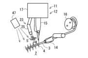
縫着工程S1は、ミシン11により基層2へ縫製糸4を縫い込むことによって繊維束3を基層2へ縫着する工程である。また、接着用樹脂付与工程S2は、ミシンヘッド12の付与機構23により繊維束3の縫着ルートの少なくとも一部に接着用樹脂(バインダ剤)5として液状のUV硬化性樹脂を付与する工程である。さらに、接合工程S3は、光照射機構47により繊維束3の縫着ルートの全体に対して断続的にUVライトを照射することで、UV硬化性樹脂を硬化させて、基層2、繊維束3及び縫製糸4を接着用樹脂5により接合する工程である。このように、ミシン11により縫製糸4の縫い込みを行う際に、ミシンヘッド12の付与機構23により接着用樹脂5が付与されるとともに、光照射機構47によりUV硬化性樹脂が硬化されるため、縫着工程S1と接着用樹脂付与工程S2と接合工程S3とが実質的に同時に行われる。The sewing step S1 is a step of sewing the
なお、本実施例では、光照射機構47として、シリンダヘッド12とは独立して保持枠13の上方に配置されるものを例示するが、これに限定されず、例えば、ミシンヘッド12に光照射機構47を備えてもよい。特に、回転体17に光照射機構47を備えてもよい。この場合、回転体17にスリップリングを設けることで、外部電力を光照射機構47に供給することができる。In this embodiment, the
トリミング工程S4は、打抜型(例えば、図3の打抜型41において加熱部43を除去したもの等)を用いて基層2の不要部2aを切除する工程である。The trimming process S4 is a process of cutting out
このように、縫着工程S1と接着用樹脂付与工程S2と接合工程S3とが実質的に同時に行われ、その後、トリミング工程S4が行われることで、プリフォーム1が得られる。このプリフォーム1は、接着用樹脂5(即ち、接着層5’)により基層2と繊維束3が接合されているため、プリフォーム1の形状安定性(即ち、取扱性)が高められる。そして、得られたプリフォーム1を成形型45内に配置して賦形し(賦形工程S5)、成形型45内に、熱硬化性樹脂を充填して硬化する(マトリックス形成工程S6)ことで、複合材7が得られる(図4参照)。この複合材7は、コア材8と、コア材8を埋設するマトリックス樹脂9と、を有している(図10参照)。In this way, the sewing step S1, the adhesive resin application step S2, and the joining step S3 are performed substantially simultaneously, and then the trimming step S4 is performed to obtain the
以上より、本実施例2のプリフォームの製造方法によると、上記の実施例1のプリフォームの製造方法と略同様の作用効果を奏するとともに、接着用樹脂5が、UV硬化性樹脂であり、接合工程S3が、トリミング工程S4前に、光硬化性樹脂に対して光照射を行う工程であるので、トリミング工程S4の前に、光照射により接着用樹脂を効果的に機能させることができる。As described above, the preform manufacturing method of this Example 2 provides substantially the same effects as the preform manufacturing method of Example 1 above, and since the
さらに、本実施例では、縫着工程S1と接着用樹脂付与工程S2と接合工程S3とが実質的に同時に行われるため、プリフォーム1を更に効率良く製造することができる。Furthermore, in this embodiment, the sewing step S1, the adhesive resin application step S2, and the joining step S3 are performed substantially simultaneously, so the
さらに、本実施例では、接着用樹脂(UV硬化性樹脂)5として複合材7のマトリックス樹脂9と同種のもの(例えば、エポキシ系樹脂等)を採用することで、複合材7において接着用樹脂5の接合部分の異物感が低減される。In addition, in this embodiment, the adhesive resin (UV curable resin) 5 is of the same type as the
尚、本発明においては、上記実施例に限られず、目的、用途に応じて本発明の範囲内で種々変更した実施例とすることができる。すなわち、上記実施例1、2では、1つのミシンヘッド12を備えるミシン11を例示したが、これに限定されず、例えば、複数のミシンヘッド12を備える多頭式ミシンとしてもよい。The present invention is not limited to the above-mentioned embodiment, and various modifications within the scope of the present invention are possible depending on the purpose and application. In other words, in the above-mentioned
また、上記実施例1、2では、基層2上に配置された繊維束3上に接着用樹脂5を付与する形態を例示したが、これに限定されず、例えば、繊維束3が配置される直前の基層2上に接着用樹脂5を付与するようにしてもよい。In addition, in the above Examples 1 and 2, an example was given in which
さらに、上記実施例2では、縫着工程S1と接着用樹脂付与工程S2と接合工程S3とを実質的に同時に行う形態を例示したが、これに限定されず、例えば、縫着工程S1と接着用樹脂付与工程S2とを実質的に同時に行った後に、接合工程S3(即ち、光照射機構47によるUV照射)を行うようにしてもよい。Furthermore, in the above-mentioned Example 2, the sewing step S1, the adhesive resin application step S2, and the joining step S3 are performed substantially simultaneously, but this is not limited thereto. For example, the sewing step S1 and the adhesive resin application step S2 may be performed substantially simultaneously, and then the joining step S3 (i.e., UV irradiation by the light irradiation mechanism 47) may be performed.
前述の例は単に説明を目的とするものでしかなく、本発明を限定するものと解釈されるものではない。本発明を典型的な実施形態の例を挙げて説明したが、本発明の記述および図示において使用された文言は、限定的な文言ではなく説明的および例示的なものであると理解される。ここで詳述したように、その形態において本発明の範囲または精神から逸脱することなく、添付の特許請求の範囲内で変更が可能である。ここでは、本発明の詳述に特定の構造、材料および実施例を参照したが、本発明をここにおける開示事項に限定することを意図するものではなく、むしろ、本発明は添付の特許請求の範囲内における、機能的に同等の構造、方法、使用の全てに及ぶものとする。The foregoing examples are merely illustrative and are not to be construed as limiting the invention. While the invention has been described with reference to exemplary embodiments, it is understood that the words used in describing and illustrating the invention are descriptive and exemplary rather than limiting. As detailed herein, changes may be made within the scope of the appended claims without departing from the scope or spirit of the invention in its form. While the description of the invention has been made with reference to specific structures, materials and examples, it is not intended that the invention be limited to those disclosed herein, but rather that the invention extends to all functionally equivalent structures, methods and uses within the scope of the appended claims.
本発明は上記で詳述した実施形態に限定されず、本発明の請求項に示した範囲で様々な変形または変更が可能である。The present invention is not limited to the embodiments detailed above, and various modifications and variations are possible within the scope of the claims of the present invention.
本発明は、プリフォーム(繊維集合体)ひいては複合材(繊維強化成形体)を製造する技術として広く利用される。特に、TFP(Tailored Fiber Placement)技術を利用してプリフォームを製造する技術として好適に利用される。The present invention is widely used as a technology for manufacturing preforms (fiber aggregates) and ultimately composite materials (fiber-reinforced molded bodies). In particular, it is suitable for use as a technology for manufacturing preforms using TFP (Tailored Fiber Placement) technology.
1;プリフォーム、2;基層、2a;不要部、3;繊維束、4;縫製糸、5;接着用樹脂、7;複合材、11;ミシン、12;ミシンヘッド、16;ボビン、17;回転体、23;付与機構、24;ロータリージョイント、25;ノズル、27;供給通路、41;打抜型、43;加熱部、45;成形型、S1;縫着工程、S2;接着用樹脂付与工程、S3;接合工程、S4;トリミング工程、S5;賦形工程、S6;マトリックス形成工程。1; preform, 2; base layer, 2a; unnecessary portion, 3; fiber bundle, 4; sewing thread, 5; adhesive resin, 7; composite material, 11; sewing machine, 12; sewing machine head, 16; bobbin, 17; rotating body, 23; application mechanism, 24; rotary joint, 25; nozzle, 27; supply passage, 41; punching die, 43; heating section, 45; molding die, S1; sewing process, S2; adhesive resin application process, S3; joining process, S4; trimming process, S5; shaping process, S6; matrix formation process.
Claims (8)
Translated fromJapanese前記基層へ縫製糸を縫い込むことによって前記繊維束を前記基層へ縫着する縫着工程と、
前記繊維束の縫着ルートの少なくとも一部に接着用樹脂を付与する接着用樹脂付与工程と、
前記基層、前記繊維束及び前記縫製糸のうちの2以上を前記接着用樹脂により接合する接合工程と、
前記基層の不要部を切除するトリミング工程と、を備え、
前記縫製糸の縫い込みを行う際に、前記接着用樹脂の付与を行うことによって、前記縫着工程と、前記接着用樹脂付与工程と、を実質的に同時に行うことを特徴とするプリフォームの製造方法。 A method for manufacturing a preform that serves as a core material of a composite material, the preform having a base layer and a fiber bundle sewn to the base layer, comprising the steps of:
a sewing step of sewing the fiber bundle to the base layer by sewing a sewing thread into the base layer;
an adhesive resin applying step of applying an adhesive resin to at least a part of the sewing route of the fiber bundle;
a bonding step of bonding two or more of the base layer, the fiber bundle, and the sewing thread with the adhesive resin;
A trimming step of removing unnecessary portions of the base layer,
A method for manufacturing a preform, characterized in that the adhesive resin is applied when the sewing thread is sewn in, thereby performing the sewing step and the adhesive resin application step substantially simultaneously.
ミシンヘッドが前記接着用樹脂を付与する付与機構を有する請求項1に記載のプリフォームの製造方法。 The sewing is performed using a sewing machine,
The method for producing a preform according to claim 1, wherein the machine head has an application mechanism for applying the adhesive resin.
前記付与機構は、前記回転体に設けられるロータリージョイントと、前記ロータリージョイントに形成された前記接着用樹脂の供給通路に接続されるノズルと、を備える請求項2に記載のプリフォームの製造方法。 The sewing machine head includes a sewing needle and a rotor that is rotatably provided around an axis of the sewing needle and has a bobbin around which the fiber bundle is wound.
The method for manufacturing a preform according to claim 2 , wherein the application mechanism comprises: a rotary joint provided on the rotating body; and a nozzle connected to a supply passage for the adhesive resin formed in the rotary joint.
前記打抜型が、打ち抜きの際に、前記接着用樹脂を機能させることによって、前記トリミング工程と、前記接合工程と、を実質的に同時に行う請求項1乃至3のうちのいずれかに記載のプリフォームの製造方法。 The trimming step is a step of cutting off an unnecessary portion of the base layer using a punch die,
The method for producing a preform according to any one of claims 1 to 3, wherein the punching die causes the adhesive resin to function during punching, thereby carrying out the trimming step and the joining step substantially simultaneously.
前記打抜型は、加熱部を有し、
前記加熱部の加熱により、前記熱可塑性樹脂を溶融、及び/又は、前記熱硬化性樹脂を硬化、させて前記接着用樹脂を機能させる請求項4に記載のプリフォームの製造方法。 The adhesive resin is a thermoplastic resin and/or a thermosetting resin,
The punching die has a heating section,
The method for producing a preform according to claim 4, wherein the adhesive resin is made to function by melting the thermoplastic resin and/or curing the thermosetting resin through heating by the heating unit.
前記接合工程は、前記トリミング工程前に、前記光硬化性樹脂に対して光照射を行う工程である請求項1乃至3のうちのいずれかに記載のプリフォームの製造方法。 The adhesive resin is a photocurable resin,
The method for producing a preform according to any one of claims 1 to 3, wherein the joining step is a step of irradiating the photocurable resin with light before the trimming step.
前記成形型内に、熱硬化性樹脂を充填して硬化、又は、熱可塑性樹脂を充填して固化、するマトリックス形成工程と、を備えることを特徴とする複合材の製造方法。 A shaping step of placing the preform obtained by the method for producing a preform according to any one of claims 1 to 6 in a molding die and shaping the preform;
and a matrix formation step of filling the mold with a thermosetting resin and curing it, or filling the mold with a thermoplastic resin and solidifying it.
前記基層へ縫製糸の縫い込みを行う際に、接着用樹脂を実質的に同時に付与する付与機構を備えるミシンヘッドを有することを特徴とするプリフォーム製造用ミシン。 Asewing machine for manufacturing a preform, the sewing machine comprising: a base layer; and a fiber bundle sewn to the base layer, the preform being used as a core material of a composite material, the sewing machine comprising:
A sewing machine for manufacturing a preform, comprising a sewing machine head equipped with an application mechanism for applying an adhesive resinsubstantially simultaneouslywhen sewing a sewing thread into the base layer .
Priority Applications (1)
| Application Number | Priority Date | Filing Date | Title |
|---|---|---|---|
| JP2021027938AJP7528818B2 (en) | 2021-02-24 | 2021-02-24 | Preform manufacturing method, composite material manufacturing method, and sewing machine for manufacturing preforms |
Applications Claiming Priority (1)
| Application Number | Priority Date | Filing Date | Title |
|---|---|---|---|
| JP2021027938AJP7528818B2 (en) | 2021-02-24 | 2021-02-24 | Preform manufacturing method, composite material manufacturing method, and sewing machine for manufacturing preforms |
Publications (2)
| Publication Number | Publication Date |
|---|---|
| JP2022129277A JP2022129277A (en) | 2022-09-05 |
| JP7528818B2true JP7528818B2 (en) | 2024-08-06 |
Family
ID=83150368
Family Applications (1)
| Application Number | Title | Priority Date | Filing Date |
|---|---|---|---|
| JP2021027938AActiveJP7528818B2 (en) | 2021-02-24 | 2021-02-24 | Preform manufacturing method, composite material manufacturing method, and sewing machine for manufacturing preforms |
Country Status (1)
| Country | Link |
|---|---|
| JP (1) | JP7528818B2 (en) |
Families Citing this family (2)
| Publication number | Priority date | Publication date | Assignee | Title |
|---|---|---|---|---|
| TR2022004472A2 (en)* | 2022-03-23 | 2022-04-21 | Plascam Plastik Oto Cam Sanayi Ve Ticaret Anonim Sirketi | TUNNEL BRACKET AND PRODUCTION METHOD |
| CN119243420B (en)* | 2024-10-11 | 2025-10-03 | 天津工业大学 | A sewing device and sewing method for small-size capped radome fabric |
Citations (2)
| Publication number | Priority date | Publication date | Assignee | Title |
|---|---|---|---|---|
| JP2003020542A (en) | 2001-07-06 | 2003-01-24 | Toray Ind Inc | Carbon fiber fabric, method for molding using the same, carbon fiber-reinforced plastic and aircraft structural member |
| JP2007160587A (en) | 2005-12-12 | 2007-06-28 | Toray Ind Inc | Multilayered base material, preform and manufacturing method of preform |
Family Cites Families (2)
| Publication number | Priority date | Publication date | Assignee | Title |
|---|---|---|---|---|
| JPH09201829A (en)* | 1996-01-26 | 1997-08-05 | Mitsubishi Electric Corp | Resin injection device |
| JPH11291240A (en)* | 1998-04-13 | 1999-10-26 | Kobe Steel Ltd | Production of glass fiber preform |
- 2021
- 2021-02-24JPJP2021027938Apatent/JP7528818B2/enactiveActive
Patent Citations (2)
| Publication number | Priority date | Publication date | Assignee | Title |
|---|---|---|---|---|
| JP2003020542A (en) | 2001-07-06 | 2003-01-24 | Toray Ind Inc | Carbon fiber fabric, method for molding using the same, carbon fiber-reinforced plastic and aircraft structural member |
| JP2007160587A (en) | 2005-12-12 | 2007-06-28 | Toray Ind Inc | Multilayered base material, preform and manufacturing method of preform |
Also Published As
| Publication number | Publication date |
|---|---|
| JP2022129277A (en) | 2022-09-05 |
Similar Documents
| Publication | Publication Date | Title |
|---|---|---|
| US11571837B2 (en) | Process of making a fiber preform of commingled fiber bundle for overmolding | |
| KR101967105B1 (en) | Additive manufacturing system implementing hardener pre-impregnation | |
| US10828829B2 (en) | Additive manufacturing system having adjustable nozzle configuration | |
| US10759114B2 (en) | System and print head for continuously manufacturing composite structure | |
| JP7528818B2 (en) | Preform manufacturing method, composite material manufacturing method, and sewing machine for manufacturing preforms | |
| CA1287716C (en) | Resin transfer molding core, preform and process | |
| US9511543B2 (en) | Method and apparatus for continuous composite three-dimensional printing | |
| US20180229430A1 (en) | Multi-stage additive manufacturing system | |
| CA3032622A1 (en) | Additive manufacturing system having in-situ fiber splicing | |
| US20150068352A1 (en) | Lightweight steering column of fibre composite material | |
| KR20190110522A (en) | Additive manufacturing system with automatic stiffener threading | |
| JP2012016948A (en) | Method for manufacturing component of composite structure | |
| WO2018048805A1 (en) | Additive manufacturing system having in-head fiber teasing | |
| JP2016211139A (en) | Bundle of roving, method to manufacture bundle of roving and method to manufacture workpiece | |
| CN110884170A (en) | Fiber continuous winding reinforced thermoplastic pipe, manufacturing system and method thereof | |
| CN115298367B (en) | Impregnated yarn, ribbed thin-walled composite product containing impregnated yarn, and methods of making the yarn and the composite product | |
| JP6701203B2 (en) | Three-dimensional high strength fiber composite member and manufacturing method thereof | |
| CA2615464A1 (en) | Fixing thread for sewing together reinforcing fibers | |
| DE102007054087B4 (en) | Method for producing a fiber composite component and device therefor | |
| JP7459770B2 (en) | Sewing machine for manufacturing preforms and method for manufacturing preforms | |
| KR20180080950A (en) | Planar element with partially fixing special line, manufacturing apparatus and manufacturing method | |
| JP7625819B2 (en) | Method for producing fiber-reinforced molding | |
| JP7543821B2 (en) | Method for producing fiber-reinforced molding | |
| JPH05164284A (en) | Manufacture of fiber reinforced resin tube fitting | |
| JP2022171389A (en) | preform |
Legal Events
| Date | Code | Title | Description |
|---|---|---|---|
| A621 | Written request for application examination | Free format text:JAPANESE INTERMEDIATE CODE: A621 Effective date:20230803 | |
| A977 | Report on retrieval | Free format text:JAPANESE INTERMEDIATE CODE: A971007 Effective date:20240419 | |
| A131 | Notification of reasons for refusal | Free format text:JAPANESE INTERMEDIATE CODE: A131 Effective date:20240430 | |
| A521 | Request for written amendment filed | Free format text:JAPANESE INTERMEDIATE CODE: A523 Effective date:20240606 | |
| TRDD | Decision of grant or rejection written | ||
| A01 | Written decision to grant a patent or to grant a registration (utility model) | Free format text:JAPANESE INTERMEDIATE CODE: A01 Effective date:20240625 | |
| A61 | First payment of annual fees (during grant procedure) | Free format text:JAPANESE INTERMEDIATE CODE: A61 Effective date:20240708 | |
| R150 | Certificate of patent or registration of utility model | Ref document number:7528818 Country of ref document:JP Free format text:JAPANESE INTERMEDIATE CODE: R150 |