JP7528719B2 - Liquid ejection device and method for filling a liquid ejection head - Google Patents
Liquid ejection device and method for filling a liquid ejection headDownload PDFInfo
- Publication number
- JP7528719B2 JP7528719B2JP2020180478AJP2020180478AJP7528719B2JP 7528719 B2JP7528719 B2JP 7528719B2JP 2020180478 AJP2020180478 AJP 2020180478AJP 2020180478 AJP2020180478 AJP 2020180478AJP 7528719 B2JP7528719 B2JP 7528719B2
- Authority
- JP
- Japan
- Prior art keywords
- liquid
- filter
- ink
- valve
- upstream chamber
- Prior art date
- Legal status (The legal status is an assumption and is not a legal conclusion. Google has not performed a legal analysis and makes no representation as to the accuracy of the status listed.)
- Active
Links
Images


Classifications
- B—PERFORMING OPERATIONS; TRANSPORTING
- B41—PRINTING; LINING MACHINES; TYPEWRITERS; STAMPS
- B41J—TYPEWRITERS; SELECTIVE PRINTING MECHANISMS, i.e. MECHANISMS PRINTING OTHERWISE THAN FROM A FORME; CORRECTION OF TYPOGRAPHICAL ERRORS
- B41J2/00—Typewriters or selective printing mechanisms characterised by the printing or marking process for which they are designed
- B41J2/005—Typewriters or selective printing mechanisms characterised by the printing or marking process for which they are designed characterised by bringing liquid or particles selectively into contact with a printing material
- B41J2/01—Ink jet
- B41J2/015—Ink jet characterised by the jet generation process
- B41J2/04—Ink jet characterised by the jet generation process generating single droplets or particles on demand
- B41J2/045—Ink jet characterised by the jet generation process generating single droplets or particles on demand by pressure, e.g. electromechanical transducers
- B—PERFORMING OPERATIONS; TRANSPORTING
- B41—PRINTING; LINING MACHINES; TYPEWRITERS; STAMPS
- B41J—TYPEWRITERS; SELECTIVE PRINTING MECHANISMS, i.e. MECHANISMS PRINTING OTHERWISE THAN FROM A FORME; CORRECTION OF TYPOGRAPHICAL ERRORS
- B41J2/00—Typewriters or selective printing mechanisms characterised by the printing or marking process for which they are designed
- B41J2/005—Typewriters or selective printing mechanisms characterised by the printing or marking process for which they are designed characterised by bringing liquid or particles selectively into contact with a printing material
- B41J2/01—Ink jet
- B41J2/17—Ink jet characterised by ink handling
- B41J2/175—Ink supply systems ; Circuit parts therefor
- B41J2/17503—Ink cartridges
- B41J2/17506—Refilling of the cartridge
- B41J2/17509—Whilst mounted in the printer
- B—PERFORMING OPERATIONS; TRANSPORTING
- B41—PRINTING; LINING MACHINES; TYPEWRITERS; STAMPS
- B41J—TYPEWRITERS; SELECTIVE PRINTING MECHANISMS, i.e. MECHANISMS PRINTING OTHERWISE THAN FROM A FORME; CORRECTION OF TYPOGRAPHICAL ERRORS
- B41J2/00—Typewriters or selective printing mechanisms characterised by the printing or marking process for which they are designed
- B41J2/005—Typewriters or selective printing mechanisms characterised by the printing or marking process for which they are designed characterised by bringing liquid or particles selectively into contact with a printing material
- B41J2/01—Ink jet
- B41J2/17—Ink jet characterised by ink handling
- B41J2/175—Ink supply systems ; Circuit parts therefor
- B41J2/17563—Ink filters
- B—PERFORMING OPERATIONS; TRANSPORTING
- B41—PRINTING; LINING MACHINES; TYPEWRITERS; STAMPS
- B41J—TYPEWRITERS; SELECTIVE PRINTING MECHANISMS, i.e. MECHANISMS PRINTING OTHERWISE THAN FROM A FORME; CORRECTION OF TYPOGRAPHICAL ERRORS
- B41J2/00—Typewriters or selective printing mechanisms characterised by the printing or marking process for which they are designed
- B41J2/005—Typewriters or selective printing mechanisms characterised by the printing or marking process for which they are designed characterised by bringing liquid or particles selectively into contact with a printing material
- B41J2/01—Ink jet
- B41J2/17—Ink jet characterised by ink handling
- B41J2/18—Ink recirculation systems
Landscapes
- Ink Jet (AREA)
- Particle Formation And Scattering Control In Inkjet Printers (AREA)
Description
Translated fromJapanese本発明は、液体噴射装置及び液体噴射ヘッドの充填方法に関し、特に、液体としてインクを噴射するインクジェット式記録装置及びインクジェット式記録ヘッドの充填方法に関する。The present invention relates to a liquid ejection device and a method for filling a liquid ejection head, and in particular to an inkjet recording device that ejects ink as the liquid, and a method for filling an inkjet recording head.
インクジェット式プリンターやプロッター等のインクジェット式記録装置に代表される液体噴射装置は、カートリッジやタンク等に貯留されたインクなどの液体を液滴として噴射可能な液体噴射ヘッドを具備する。液体噴射ヘッドとしては、フィルターを備えたフィルター室と、液体を吐出するノズルが設けられた液体噴射部とを具備する。カートリッジ等から供給されたインクは、フィルター室のフィルターを通過し、液体噴射部に供給される。Liquid ejection devices, such as inkjet printers and plotters, are equipped with a liquid ejection head capable of ejecting liquid such as ink stored in a cartridge or tank as droplets. The liquid ejection head is equipped with a filter chamber equipped with a filter, and a liquid ejection section provided with nozzles for ejecting liquid. Ink supplied from a cartridge or the like passes through the filter in the filter chamber and is supplied to the liquid ejection section.
例えば、特許文献1に開示されるインクジェット式記録ヘッドでは、ポンプなどの加圧機構によりカートリッジやタンク等からインクジェット式記録ヘッドにインクを圧送し、フィルター室にインクを充填する充填動作が行われる。充填動作では、始めにフィルターよりも上流側にインクが充填される。そして、インクの圧力がフィルターのバブルポイントを超えると、インクがフィルターを通過し、フィルターよりも下流側にもインクが充填される。For example, in the inkjet recording head disclosed in
上述の充填動作を行うとき、フィルター室においてフィルターよりも上流側に存在する気泡は、フィルターを通過する際に細かな気泡となり、フィルター室から液体噴射部のノズルに至るまでの流路の途中に残留してしまう虞がある。When performing the above-mentioned filling operation, air bubbles present upstream of the filter in the filter chamber may turn into fine bubbles as they pass through the filter, and may remain in the flow path from the filter chamber to the nozzle of the liquid injection section.
なお、このような問題はインクジェット式記録装置だけではなく、インク以外の液体を噴射する液体噴射装置においても同様に存在する。Note that this problem exists not only in inkjet recording devices, but also in liquid ejection devices that eject liquids other than ink.
上記課題を解決する本発明の好適な態様に係る液体噴射装置の一態様は、液体を噴射する液体噴射部と、液体を貯留する液体貯留部と、液体が通過するフィルターによって区画された上流室と下流室とを含むフィルター室と、前記液体貯留部から前記上流室へ液体が流動する供給路と、前記上流室から前記液体貯留部へ液体が流動する排出路と、前記排出路を開閉する開閉弁と、前記液体貯留部から前記上流室へ液体を流動させるために液体を加圧する加圧機構と、を備え、前記開閉弁を開いた状態で、液体が前記フィルターを通過しないように前記加圧機構を駆動することで前記上流室を液体で満たした後、前記駆動によって前記液体貯留部から前記供給路、前記上流室、前記排出路へ向かって液体が流動している間に前記開閉弁を閉じる充填動作を行う、ことを特徴とする液体噴射装置にある。One aspect of the liquid injection device according to a preferred aspect of the present invention that solves the above problem is a liquid injection device that includes a liquid injection unit that injects liquid, a liquid storage unit that stores liquid, a filter chamber including an upstream chamber and a downstream chamber partitioned by a filter through which the liquid passes, a supply path through which liquid flows from the liquid storage unit to the upstream chamber, a discharge path through which liquid flows from the upstream chamber to the liquid storage unit, an on-off valve that opens and closes the discharge path, and a pressurizing mechanism that pressurizes the liquid to flow from the liquid storage unit to the upstream chamber, and is characterized in that, with the on-off valve open, the upstream chamber is filled with liquid by driving the pressurizing mechanism so that the liquid does not pass through the filter, and then a filling operation is performed to close the on-off valve while liquid is flowing from the liquid storage unit toward the supply path, the upstream chamber, and the discharge path by the drive.
上記課題を解決する本発明の好適な態様に係る液体噴射ヘッドの充填方法の一態様は、液体を噴射する液体噴射部と、液体を貯留する液体貯留部と、液体が通過するフィルターによって区画された上流室と下流室とを含むフィルター室と、前記液体貯留部から前記上流室へ液体が流動する供給路と、前記上流室から前記液体貯留部へ液体が流動する排出路と、前記排出路を開閉する開閉弁と、前記液体貯留部から前記上流室へ液体を流動させるために液体を加圧する加圧機構と、を備える液体噴射ヘッドの充填方法であって、前記開閉弁を開いた状態で、液体が前記フィルターを通過しないように前記加圧機構を駆動することで前記上流室を液体で満たした後、前記駆動によって前記液体貯留部から前記供給路、前記上流室、前記排出路へ向かって液体が流動している間に前記開閉弁を閉じる充填動作を行う、ことを特徴とする液体噴射ヘッドの充填方法にある。One aspect of the method for filling a liquid jet head according to a preferred aspect of the present invention that solves the above problem is a method for filling a liquid jet head that includes a liquid jet unit that jets liquid, a liquid storage unit that stores liquid, a filter chamber including an upstream chamber and a downstream chamber partitioned by a filter through which the liquid passes, a supply path through which liquid flows from the liquid storage unit to the upstream chamber, a discharge path through which liquid flows from the upstream chamber to the liquid storage unit, an on-off valve that opens and closes the discharge path, and a pressurizing mechanism that pressurizes the liquid to flow from the liquid storage unit to the upstream chamber, characterized in that the method for filling a liquid jet head includes a filling operation that closes the on-off valve while the on-off valve is open and the pressurizing mechanism is driven to prevent the liquid from passing through the filter.
〈実施形態1〉
以下に本発明を実施形態に基づいて詳細に説明する。ただし、以下の説明は、本発明の一態様を示すものであって、本発明の範囲内で任意に変更可能である。各図において同じ符号を付したものは、同一の部材を示しており、適宜説明が省略されている。 First Embodiment
The present invention will be described in detail below based on an embodiment. However, the following description shows one aspect of the present invention, and can be modified as desired within the scope of the present invention. In each drawing, the same reference numerals indicate the same members, and the description will be omitted as appropriate.
各図においてX、Y、Zは、互いに直交する3つの空間軸を表している。本明細書では、これらの軸に沿った方向をX方向、Y方向、及びZ方向とする。また、Y軸を中心としてX軸を角度θ回転させたものをV軸、Z軸を角度θ回転させたものをW軸とし、これらの軸に沿った方向をV方向、W方向とする。各図の矢印が向かう方向を正(+)方向、矢印の反対方向を負(-)方向として説明する。Z方向は、鉛直方向を示し、+Z方向は鉛直下向き、-Z方向は鉛直上向きを示す。In each figure, X, Y, and Z represent three mutually orthogonal spatial axes. In this specification, the directions along these axes are referred to as the X direction, Y direction, and Z direction. Furthermore, the X axis rotated an angle θ around the Y axis is referred to as the V axis, and the Z axis rotated an angle θ around the Y axis is referred to as the W axis, and the directions along these axes are referred to as the V direction and W direction. In each figure, the direction indicated by the arrow is referred to as the positive (+) direction, and the opposite direction of the arrow is referred to as the negative (-) direction. The Z direction indicates the vertical direction, the +Z direction indicates the vertical downward direction, and the -Z direction indicates the vertical upward direction.
図1は、本発明の実施形態1に係る液体噴射装置の一例であるインクジェット式記録装置1の概略構成を示す図である。Figure 1 is a diagram showing the schematic configuration of an
図1に示すようにインクジェット式記録装置1は、液体の一種であるインクをインク滴として印刷用紙等の媒体Sに吐出・着弾させて、媒体Sに形成されるドットの配列により画像等の印刷を行う印刷装置である。As shown in FIG. 1, the
インクジェット式記録装置1は、インクを噴射するインクジェット式記録ヘッド100(以下、単に記録ヘッド100とも言う)から構成されたラインヘッド2と、液体供給部10と、搬送方向へ媒体Sを搬送する搬送部4と、支持台5と、を具備し、これらラインヘッド2、液体供給部10、搬送部4及び支持台5が筐体3内に収容されている。The
ラインヘッド2は、記録ヘッド100と、記録ヘッド100を保持する保持部101とを備えている。保持部101に保持される記録ヘッド100の個数は一個でもよいし複数個でもよい。保持部101は、記録ヘッド100の後述するフィルターが水平面であるXY平面に対して傾斜するように記録ヘッド100を保持する。The
ラインヘッド2は、記録ヘッド100を、インク滴の噴射方向が鉛直方向(別称、重力方向)である+Z方向をY軸周りに回転させて傾斜した+W方向となるように保持している。言い換えれば、ノズルから噴射されるインク滴の噴射方向は、+Z方向に対して-X方向に傾斜させた+W方向となっている。なお、ラインヘッド2を構成する記録ヘッド100の+Z方向に対する傾斜角度θ、すなわち、インク滴の噴射方向であるW方向の+Z方向に対する傾斜角度θは、例えば、0<θ≦180°の範囲内に設定される。θが90°を超える場合は、インク滴の噴射方向に-Z方向の成分を含むことになる。The
なお、本実施形態では、ラインヘッド2の記録ヘッド100は保持部101により水平面に対して常時傾斜した状態に保持されているが、常時傾斜した状態に保持されている必要はない。例えば、ラインヘッド2の水平面に対する傾きを調整する調整機構を設けることで、吸引クリーニングなどのメンテナンス動作や、媒体Sにインクを噴射する印刷時のみに記録ヘッド100を傾斜した状態に保持する構成であってもよい。In this embodiment, the
本実施形態の媒体Sは、例えば、連続紙などの記録用紙、布、樹脂フィルム等からなる媒体の一種であり、操出軸8にロール状に巻き付けられた状態で保持されている。この媒体Sは、搬送部4によって記録ヘッド100のノズルが形成されたノズル面に対して間隔を空けて配置されたプラテン等の支持台5上に搬送され、支持台5上でラインヘッド2によって印刷が行われる。支持台5で記録ヘッド100によって印刷された媒体Sは、搬送部4によって巻取軸9に巻き取られるように構成されている。The medium S in this embodiment is a type of medium made of, for example, continuous paper or other recording paper, cloth, or resin film, and is held in a rolled state on the
支持台5の媒体Sが載置される載置面は、記録ヘッド100のノズル面の傾斜角度に合わせて傾斜して配置されている。すなわち、印刷動作の際にノズル面の各ノズルと媒体Sとの間隔が一定となるように、ノズル面と支持台5との傾斜角度θが設定されている。換言すれば、支持台5の載置面は、V軸及びY軸で規定されるVY平面に平行であり、XY平面との角度が傾斜角度θとなっている。V方向は、W方向に直交する方向であり、且つ、Y方向に直交する方向である。媒体Sは、支持台5の載置面においては、搬送部4により+V方向又は-V方向に搬送される。以後、この+V方向又は-V方向を搬送方向ともいう。The mounting surface of the support base 5 on which the medium S is placed is inclined to match the inclination angle of the nozzle surface of the
記録ヘッド100を備えるラインヘッド2は、媒体Sの搬送方向に直交するY方向が長手方向となっており、Y方向における印刷範囲が、媒体SのY方向の印刷範囲以上となるように配置された多数のノズルを備えている。つまり、本実施形態のラインヘッド2は、印刷動作中に筐体3に対してY軸に沿って移動しないように固定されている。The
なお、媒体Sは、連続紙のようなものに限定されず、記録ヘッド100のノズルから噴射されたインク滴が着弾可能な種々の被噴射媒体を採用することができる。例えば、立体的な形状を有する被噴射媒体に対してインク滴を噴射させる用途にも本発明を適用することができる。また、支持台5は、媒体Sを載置する載置面が平坦なプラテンに限定されず、媒体Sを載置する載置面が曲面となるドラム等の所謂ドラムプラテンであってもよい。また、無端ベルト等の搬送ベルトによって媒体Sの裏面側を支持するようにしてもよい。The medium S is not limited to continuous paper and the like, and various types of receiving media on which ink droplets ejected from the nozzles of the
搬送部4は、給紙ローラー6と搬送ローラー7とを備えている。給紙ローラー6は、媒体Sを挟持した状態で互いに反対方向に同期回転可能な上下一対のローラーにより構成されている。給紙ローラー6は、図示しないモーターの動力によって駆動され、媒体Sを操出軸8側から支持台5側に供給する。搬送ローラー7は、給紙ローラー6とは支持台5を挟んで反対側に配置され、印刷後の媒体Sを巻取軸9側に案内する。なお、媒体Sは、必ずしも巻取軸9に巻き取られなくてもよい。また、本実施形態では、搬送部4は、給紙ローラー6と搬送ローラー7とを備えたものを例示したが、特にこれに限定されず、ベルトやドラムによって媒体Sを搬送するものであってもよい。The
図2を用いて、液体供給部10及び記録ヘッド100について説明する。図2は、液体供給部10及び記録ヘッド100の概略構成図である。なお、図2ではラインヘッド2については記録ヘッド100のみを図示し、保持部101の図示は省略している。The
液体供給部10は、インクを記録ヘッド100に供給するための機構であり、本実施形態では、メインタンク11及び中間タンク12と、供給路13と、排出路14と、開閉弁15と、ポンプ16と、タンク間供給路17と、を備える。The
メインタンク11は、インクを貯留する容器であり、そのインクを中間タンク12に供給する。具体的には、メインタンク11と中間タンク12とは、タンク間供給路17で接続されている。また、タンク間供給路17の途中には図示しないポンプが設けられている。このような構成により、図示しないポンプによってメインタンク11からタンク間供給路17を介して中間タンク12にインクが供給される。The
なお、メインタンク11から中間タンク12にインクを供給するタイミングは、特に限定はない。例えば、中間タンク12に貯留されているインクの液面が所定の高さよりも低くなった場合や、インクの量が所定量よりも少なくなった場合にメインタンク11から中間タンク12にインクが供給される。The timing for supplying ink from the
中間タンク12は、インクを貯留する液体貯留部の一例である。中間タンク12は、メインタンク11から供給されたインクを貯留する。中間タンク12と記録ヘッド100とは、供給路13及び排出路14で接続されている。The
供給路13は、中間タンク12から後述する上流室50Aにインクが流動する流路である。排出路14は、後述する上流室50Aから中間タンク12へインクが流動する流路である。本実施形態では供給路13及び排出路14はそれぞれ一本であるが、本数に限定はない。The
開閉弁15は、排出路14を開閉する装置である。開閉弁15の具体的な構成に特に限定はなく、電磁式や圧力式などの弁を用いることができる。また、開閉弁15は、後述する制御部18によって開閉することが可能となっている。The on-off
ポンプ16は、中間タンク12に貯留されたインクを記録ヘッド100へ流動させるためにインクを加圧する加圧機構の一例である。具体的には、チューブポンプやダイアフラムポンプなどがポンプ16として供給路13に設けられている。また、ポンプ16は、後述する制御部18によって運転や停止することが可能となっている。The
なお、加圧機構はポンプ16に限定されず、例えば、中間タンク12を外部から押圧することで中間タンク12に貯留されたインクを加圧する押圧手段であってもよい。他にも、記録ヘッド100と中間タンク12との鉛直方向の相対位置を調整して発生する水頭圧差を用いる装置を加圧機構として用いてもよい。また、ポンプ16は供給路13の途中に設けた構成を例示したが、これに限定されない。例えば、中間タンク12にポンプ16を設けてもよい。The pressurizing mechanism is not limited to the
記録ヘッド100は、フィルター部材20と、液体噴射部30と、を具備する。
液体噴射部30は、インクを噴射するノズル31が設けられたノズル面32を有する。本実施形態では、複数のノズル31がY方向に並設されたノズル列がノズル面32に形成されている。ノズル列の数に特に限定はない。また、記録ヘッド100は一つの液体噴射部30を備えた構成を例示したが、これに限定されず、複数の液体噴射部30を備えていてもよい。 The
The
また、液体噴射部30の図示しない内部には、ノズル31に連通する流路と、流路内のインクに圧力変化を生じさせる圧力発生手段等が設けられている。圧力発生手段としては、例えば、電気機械変換機能を呈する圧電材料を有する圧電アクチュエーターの変形によって液体流路の容積を変化させて液体流路内のインクに圧力変化を生じさせてノズル31からインク滴を吐出させるものや、流路内に発熱素子を配置して、発熱素子の発熱で発生するバブルによってノズル31からインク滴を吐出するものや、振動板と電極との間に静電気力を発生させて、静電気力によって振動板を変形させてノズル31からインク滴を吐出させるいわゆる静電式アクチュエーターなどを使用することができる。In addition, inside the liquid ejection unit 30 (not shown), a flow path communicating with the
図3を用いて、本実施形態に係るフィルター部材20について説明する。図3は記録ヘッドの断面図であり、図1と同様に、インクの噴射方向が+W方向となるように配置された状態における記録ヘッド100を示している。The
フィルター部材20は、第1フィルター部材21及び第2フィルター部材22が積層され、内部にフィルター室50を有している。具体的には、フィルター部材20は、図示しない保持部101側(図3に示す-W方向側)に設けられた第1フィルター部材21と、第1フィルター部材21の液体噴射部30側(図3に示す+W方向側)に設けられた第2フィルター部材22とを具備し、第1フィルター部材21及び第2フィルター部材22は積層されている。第1フィルター部材21及び第2フィルター部材22は、例えば樹脂材料から形成することができるが、特に材料は樹脂材料に限定されない。The
第1フィルター部材21には、第2フィルター部材22側(図3に示す+W方向側)の面に第1凹部51が形成されている。第1フィルター部材21の図示しない保持部101側(図3に示す-W方向側)には、W方向に貫通した貫通孔である流入口54及び排出口59が形成されている。排出口59は、鉛直方向であるZ方向において、流入口54よりも上方に位置している。A
第2フィルター部材22には、第1フィルター部材21側(図3に示す-W方向側)の面に第2凹部52が形成されている。第2フィルター部材22の液体噴射部30側(図3に示す+W方向側)には、W方向に貫通した貫通孔である流出口56が形成されている。流出口56は、液体噴射部30の内部に設けられた図示しない流路に接続されている。A
フィルター室50は、インクが通過するフィルター57によって区画された上流室50Aと下流室50Bとを含む。本実施形態では、第1フィルター部材21と第2フィルター部材22とが積層されることで、第1凹部51と第2凹部52からなるフィルター室50が形成されている。そして、第2凹部52の開口を覆うようにしてフィルター57が設けられている。このようなフィルター57によりフィルター室50は、上流室50Aと下流室50Bに区画されている。The
上流室50Aは、フィルター室50においてフィルター57よりも上流側の空間であり、下流室50Bは、フィルター57よりも下流側の空間である。フィルター57よりも上流側の空間とは、フィルター室50のフィルター57によって区画された2つの空間のうち、インクを噴射するノズル31から相対的に遠い方をいい、下流側の空間とは当該2つの空間のうちノズル31に相対的に近い方をいう。The
フィルター57は、インクに含まれる異物や気泡などを捕捉するものであり、本実施形態では第2フィルター部材22に熱溶着や接着剤などで固定されている。また、フィルター57は、例えば、線状の金属を綾畳みにしたものや、SUSからなる平板状部材に多数の孔を設けたものや、不織布などを挙げることができる。The
また、フィルター57の流路抵抗は、排出路14の全体の流路抵抗よりも大きい。ここでいう排出路14の流路抵抗とは、上流室50Aの排出口59から中間タンク12までの流路抵抗である。The flow resistance of the
このように構成されたフィルター部材20では、流入口54には供給路13が接続され、排出口59には排出路14が接続されており、次のようにインクが流通する。フィルター室50の上流室50Aには、中間タンク12から供給路13及び流入口54を介してインクが供給される。また、フィルター室50の上流室50Aから、フィルター57を通過しなかったインクが排出口59及び排出路14を介して中間タンク12へ排出される。また、上流室50Aからフィルター57を通過して下流室50Bに供給されたインクは、流出口56を介して液体噴射部30に供給される。In the
また、上述したインクジェット式記録装置1は、メインタンク11、タンク間供給路17、中間タンク12、供給路13、排出路14、開閉弁15及びポンプ16からなる液体供給部10を一つの記録ヘッド100について一つ設けた構成としたが、このような構成に限定されない。一つの記録ヘッド100について複数の液体供給部10からインクを供給するように構成してもよい。例えば、インクジェット式記録装置1は、色の異なる複数種類のインクをそれぞれ供給する複数の液体供給部10を備える構成とする。そして、記録ヘッド100に複数のフィルター室50を設け、各フィルター室50に各液体供給部10からインクが供給されるように構成する。The
また、上述したインクジェット式記録装置1は、一つの記録ヘッド100を有するラインヘッド2を備えた構成としたが、このような構成に限定されず、複数の記録ヘッド100を備えていてもよい。この場合、一つの液体供給部10から各記録ヘッド100にインクを分配する、又は複数の液体供給部10のそれぞれから各記録ヘッド100にインクを分配するように構成すればよい。The
例えば、複数の記録ヘッド100を保持する保持部101に流路を設け、当該流路を途中で記録ヘッド100の数だけ分岐させる。そして、液体供給部10から供給されるインクが保持部101に設けられた流路を経由して各記録ヘッド100の上流室50Aに供給されるように構成する。他にも、中間タンク12と各記録ヘッド100とをそれぞれ供給路13及び排出路14で接続し、中間タンク12から各記録ヘッド100にインクが分配されるように構成してもよい。For example, a flow path is provided in a
また、上述したインクジェット式記録装置1は、一つの記録ヘッド100に一つの液体噴射部30を備える構成としたが、これに限定されず、液体噴射部30は2以上の複数個あってもよい。この場合、例えば、流出口56に連通し、途中で液体噴射部30の個数分だけ分岐した分岐流路を用い、下流室50Bから当該分岐流路を介して各液体噴射部30にインクを供給させることができる。In addition, the
本実施形態のインクジェット式記録装置1は、制御部18を備えている。制御部18は、例えば、CPU(Central Processing Unit)またはFPGA(Field Programmable Gate Array)等の制御装置と半導体メモリ等の記憶装置とを含んで構成される。制御部18は、記憶装置に記憶されたプログラムを制御装置が実行することでインクジェット式記録装置1の搬送部4、液体供給部10、記録ヘッド100等を統括的に制御する。The
制御部18は、開閉弁15及びポンプ16を制御することでインクの充填動作を実行する。充填動作とは、フィルター室50及び記録ヘッド100のインクの流路にインクが充填されていない状態からインクを充填させる動作をいう。充填動作は、例えば、インクジェット式記録装置1を初めて使用する際に行われる。他にも、インクジェット式記録装置1や記録ヘッド100のメンテナンスやクリーニング等によってフィルター室50及び記録ヘッド100のインクの流路中のインクを全て排出させた後に充填動作が行われる。The
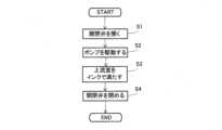
図4から図9を用いて、制御部による充填動作及び記録ヘッド100の充填方法について詳細に説明する。図4から図7は、充填動作を行っているときの記録ヘッドの断面図であり、図3と同様に、インクの噴射方向が+W方向となるように配置されている。また、図8は充填動作のフローチャートである。なお、図4~図7では白抜きの開閉弁15は開いた状態を表し、黒塗りの開閉弁15は閉じた状態を表している。The filling operation by the control unit and the method of filling the
図4に示すように、制御部18は、開閉弁15を開き(図8のステップS1)、開閉弁15が開いた状態でインクがフィルター57を通過しないようにポンプ16を駆動する(図8のステップS2)。As shown in FIG. 4, the
開閉弁15を開いてポンプ16を駆動した結果、図示しない中間タンク12から上流室50Aにインクが供給される。この状態におけるインクの圧力は、フィルター57のバブルポイントを超えないので、インクはフィルター57を通過しない。When the on-off
図5に示すように、制御部18はポンプ16を駆動することで上流室50Aをインクで満たす(図8のステップS3)。厳密には、上流室50Aから、排出路14の開閉弁15までをインクで満たす。As shown in FIG. 5, the
具体的には、制御部18は、ポンプ16を駆動してから所定時間が経過したならば上流室50Aがインクで満たされたとみなす。そのような所定時間としては、ポンプ16を駆動してから上流室50Aがインクで満たされるのに十分な時間を実測やシミュレーションなどによって得ておけばよい。Specifically, the
他の方法としては、ポンプ16を駆動してから上流室50Aがインクで満たされたときに、開閉弁15が受ける圧力やポンプ16が加圧している圧力を計測により得ておき、基準圧力とする。そして、制御部18は、開閉弁15が受ける圧力や、ポンプ16が加圧している圧力を計測しておき、それらの圧力が基準圧力に達したならば上流室50Aがインクで満たされたとみなす。As another method, when the
さらに他の方法としては、開閉弁15にインクが到達したことを検知するセンサーを設け、制御部18は、当該センサーがインクを検知したならば上流室50Aがインクで満たされたとみなしてもよい。当該センサーには、例えば静電容量式や超音波式等の液面センサーなどを採用できるが、開閉弁15にインクが到達したことを検知することができればセンサーの種類は特に限定されない。As another method, a sensor may be provided to detect when ink has reached the on-off
制御部18は、上流室50Aをインクで満たした後もポンプ16を駆動し続けており、開閉弁15は開いた状態である。また、上述したように、フィルター57の流路抵抗は排出路14の全体の流路抵抗よりも大きい。このため、インクはフィルター57を通過するよりも、排出口59から排出路14に流れる。すなわち、ポンプ16の駆動によって中間タンク12から供給路13、上流室50A、排出路14へ向かってインクが流動している。The
図6に示すように、制御部18は、ポンプ16の駆動によって中間タンク12から供給路13、上流室50A、排出路14へ向かってインクが流動している間に開閉弁15を閉じる(図8のステップS4)。開閉弁15を閉じるタイミングは、上流室50Aがインクで満たされた後の任意のタイミングでよい。As shown in FIG. 6, the
制御部18によりインクが流動した状態で開閉弁15が閉じられることで、上流室50Aから開閉弁15へ向かって流動するインクの慣性によって上流室50A内に高い圧力が発生する。この水撃作用によって、上流室50Aを流動するインクの圧力は瞬間的に上昇し、フィルター57のバブルポイントを超える。したがって、インクはフィルター57を通過して下流室50Bへ流入する。そして、図7に示すように、下流室50Bもインクで満たされ、流出口56を介して液体噴射部30にインクが供給される。When the
なお、特に図示しないが、制御部18は、フィルター室50の全体がインクで充填され、記録ヘッド100のノズル31に至るまでのインクの流路にインクが充填されたらポンプ16を停止させ、充填動作を終了する。例えば、ポンプ16を駆動させてから所定時間が経過したときや、ポンプ16を駆動させた後にノズル31からインクが噴射された事を検知したときに、フィルター室50及び記録ヘッド100のノズル31に至るまでのインクの流路がインクで充填されたと判定して、ポンプ16を停止させる。Although not specifically shown, the
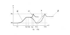
図9を用いて、インクによってフィルター57に作用する圧力の変化について説明する。図9は充填動作におけるフィルターに作用する圧力変化を示す図である。縦軸はインクによってフィルター57に作用する圧力Pであり、横軸は時刻Tである。実線αは、上述したインクジェット式記録装置1の充填動作におけるフィルター57に作用する圧力の変化を示している。点線βは、本発明の充填動作とは異なる比較例としての充填動作を行ったときのフィルターに作用する圧力の変化を示している。Using Figure 9, we will explain the change in pressure acting on the
実線αに示すように、図8のフローチャートのステップS2に相当する時刻T1において、制御部18がポンプ16を駆動する。上流室50Aではインクが徐々に増量するので、圧力Pはポンプ16を駆動する前の圧力P0よりも増大している。As shown by the solid line α, at time T1, which corresponds to step S2 in the flowchart of FIG. 8, the
図8のフローチャートのステップS3に相当する時刻T2において、制御部18により上流室50Aがインクで満たされる。この状態では、ポンプ16の駆動によって中間タンク12から供給路13、上流室50A、排出路14へ向かってインクが流動しているため、時刻T3まで圧力Pは一定となっている。At time T2, which corresponds to step S3 in the flow chart of FIG. 8, the
図8のフローチャートのステップS4に相当する時刻T3において、制御部18が開閉弁15を閉じる。上述したように供給路13、上流室50A、排出路14へ向かってインクが流動している最中に開閉弁15が閉じるため、前述の水撃作用によってフィルター57に作用するインクによる圧力Pは瞬間的に上昇し、バブルポイントPbに達する。At time T3, which corresponds to step S4 in the flow chart of FIG. 8, the
時刻T3以後は、インクがフィルター57を通過して下流室50Bに流入するので、圧力Pは低下し、その後、ほぼ一定に保たれている。After time T3, the ink passes through the
点線βに示すように、比較例に係る充填動作では、時刻T1のポンプの駆動と時刻T2の上流室50Aがインクで満たされるまでは、実線αと同様である。比較例に係る充填動作では、時刻T2の後の時刻T10においてポンプを停止する。このため、中間タンク12から供給路13、上流室50A、排出路14へ向かうインクの流動が次第になくなる。このインクの流動の停止にともない、フィルター57に作用するインクの圧力Pは徐々に低下し、ポンプ16を駆動する前の圧力P0となる。As shown by the dotted line β, the filling operation of the comparative example is similar to the solid line α from the start of pump operation at time T1 until the
比較例に係る充填動作では、その後の時刻T11において開閉弁15を閉じ、時刻T12においてポンプ16を駆動する。このような動作によって、フィルター57に作用するインクの圧力Pが増大し、時刻T13においてバブルポイントPbに到達する。時刻T13以後は、インクがフィルター57を通過して下流室50Bに流入するので、圧力Pは低下し、その後、ほぼ一定に保たれている。In the filling operation of the comparative example, the on-off
また、実線αに示すように、時刻T3で開閉弁15を閉じた時からフィルター57をインクが通過する時刻T4までにおいて、フィルター57に作用するインクの圧力の平均の時間変化率を、傾きA1とする。また、点線βに示すように、時刻T11で開閉弁15を閉じた時からフィルター57をインクが通過する時刻T13までにおいて、フィルター57に作用するインクの圧力の平均の時間変化率を、傾きBとする。傾きA1は、傾きBよりも大きくなっている。As shown by the solid line α, the average time rate of change of the ink pressure acting on the
以上に説明したインクジェット式記録装置1及び記録ヘッド100の充填方法では、図5に示したように上流室50Aをインクで満たした後においてもポンプ16を駆動し続けることで、中間タンク12から供給路13、上流室50A、排出路14へインクを流動させる。このようなインクの流動により、上流室50Aに残留している気泡がインクとともに排出路14に排出することができる。そして、図6に示したようにインクが流動している状態で開閉弁15を閉じることにより、水撃作用でフィルター57に掛るインクの圧力を瞬間的に上昇させる。これにより、フィルター57内に存在する気泡を一気に下流室50Bから記録ヘッド100へインクとともに流すことができ、フィルター57からノズル31までの間に細かい気泡が残留する虞を低減できる。In the
また、図9の実線αについて時刻T1から時刻T2までの間は、ポンプ16の駆動によって圧力を上昇させているが、時刻T3で開閉弁15を閉じることによってインクの圧力をバブルポイントPbに到達させている。換言すれば、ポンプ16の駆動のみならず、水撃作用を利用してインクの圧力を上昇させている。In addition, for the solid line α in FIG. 9, the pressure is increased by driving the
一方、比較例である点線βについては、時刻T1から時刻T2までポンプ16によって圧力を上昇させている。しかしながら、時刻T10でポンプ16を停止させるので、時刻T11で開閉弁15を閉じるときにはインクの圧力は元の圧力P0に戻っている。この状態で時刻T12においてポンプ16を駆動し、バブルポイントPbに達するまでの間、ポンプ16の駆動によってのみインクの圧力を上昇させている。On the other hand, for the comparative example, dotted line β, the pressure is increased by the
このように、比較例の充填動作はポンプ16のみを利用する一方で、本実施形態の充填動作はポンプ16のみならず水撃作用を利用する。したがって、インクの圧力をバブルポイントPbとするために、本実施形態のインクジェット式記録装置1では、比較例の充填動作で用いるポンプの最大出力よりも小さい最大出力のポンプ16を用いることができる。この結果、ポンプ16で消費するエネルギーを低減し、また、ポンプ16を小型化することができる。Thus, while the filling operation of the comparative example uses only the
さらに、図9に示したように、本実施形態に係る充填動作における傾きA1は、比較例に係る充填動作における傾きBよりも大きい。このことは、本実施形態に係る充填動作では、時刻T3の開閉弁15を閉じた後に、比較例に係る充填動作と比較して短時間でインクの圧力を上げることができることを意味する。このように短時間にインクの圧力を上げることができるので、ポンプ16の駆動時間を短縮することができる。これにより、ポンプ16の寿命を延長することができ、さらに、充填動作時にノズル31から排出されるインクの量を低減することができる。さらに、インクの量を低減できることから、ポンプ16によって加圧されるインクが貯留されている中間タンク12を小型化することができる。Furthermore, as shown in FIG. 9, the slope A1 in the filling operation according to this embodiment is larger than the slope B in the filling operation according to the comparative example. This means that in the filling operation according to this embodiment, the ink pressure can be increased in a shorter time after the on-off
〈実施形態2〉
図10及び図11を用いて、実施形態2に係るインクジェット式記録装置1について説明する。図10は充填動作のフローチャートであり、図11はフィルター57に作用する圧力の変化について説明する図である。図11の実線γは、本実施形態に係るインクジェット式記録装置1の充填動作におけるフィルター57に作用する圧力の変化を示している。なお、実施形態1と同様の部材には同一の符号を付して重複する説明は省略する。 Second Embodiment
The ink
まず、制御部18は、開閉弁15を開き(図10のステップS11)、開閉弁15が開いた状態でインクがフィルター57を通過しないようにポンプ16を駆動する(図10のステップS12)。そして、制御部18は、上流室50Aをインクで満たす(図10のステップS13)。これらのステップS11~S13は、実施形態1のステップS1~S3と同様であるので詳細な説明は省略する。First, the
次に、制御部18は、ポンプ16を停止する(図10のステップS14)。ポンプ16を停止するタイミングについては特に限定はない。Next, the
制御部18により開閉弁15は開いており、また、実施形態1で述べたようにフィルター57の流路抵抗は排出路14の全体の流路抵抗よりも大きい。このため、制御部18が上流室50Aをインクで満たした後にポンプ16を停止しても、しばらくの間、中間タンク12から供給路13、上流室50A、排出路14へ向かうインクの流動が継続する。The on-off
次に、制御部18は、制御部18は、ポンプ16の駆動によって中間タンク12から供給路13、上流室50A、排出路14へ向かってインクが流動している間に開閉弁15を閉じる(図10のステップS15)。本発明でいう「ポンプ16の駆動によってインクが流動している間」とは、実施形態1のようにポンプ16が駆動している状態でインクが流動する場合のみならず、実施形態2のようにポンプ16の駆動によってインクが流動し、その後にポンプ16を停止してからインクが流動している状態も含む。Next, the
また、図11の実線γに示すように、開閉弁15を閉じる時刻T24は、インクの圧力Pが閾値である圧力Pth以上であるときとする。圧力Pthは、開閉弁15を閉じた後の圧力PがバブルポイントPbを超えるように設定される。As shown by the solid line γ in FIG. 11, the time T24 at which the on-off
制御部18によりインクが流動した状態で開閉弁15が閉じられることで、実施形態1と同様に、上流室50Aを流動するインクの圧力は水撃作用によって瞬間的に上昇し、フィルター57のバブルポイントを超える。したがって、インクはフィルター57を通過して下流室50Bへ流入する。そして、下流室50Bもインクで満たされ、流出口56を介して液体噴射部30にインクが供給される。When the
図11を用いて、インクによってフィルター57に作用する圧力の変化について説明する。実線γに示すように、時刻T21において、制御部18がポンプ16を駆動する。上流室50Aではインクが徐々に増量するので、圧力Pはポンプ16を駆動する前の圧力P0よりも増大している。The change in pressure acting on the
時刻T22において、制御部18により上流室50Aがインクで満たされる。この状態では、ポンプ16の駆動によって中間タンク12から供給路13、上流室50A、排出路14へ向かってインクが流動しているため、時刻T23まで圧力Pは一定となっている。At time T22, the
時刻T23において、制御部18がポンプ16を停止させる。ポンプ16を停止させることでインクの流動は継続するが圧力Pは徐々に低下する。At time T23, the
時刻T24において、制御部18が開閉弁15を閉じる。上述したようにポンプ16の停止後も供給路13、上流室50A、排出路14へ向かってインクが流動している。したがって、実施形態1と同様にインクが流動している最中に開閉弁15が閉じるため、水撃作用によってフィルター57に作用するインクによる圧力Pは瞬間的に上昇し、バブルポイントPbに達する。At time T24, the
時刻T25以後は、インクがフィルター57を通過して下流室50Bに流入するので、圧力Pは低下し、その後、ほぼ一定に保たれている。After time T25, the ink passes through the
また、実線γに示すように、時刻T24で開閉弁15を閉じた時からフィルター57をインクが通過する時刻T25までにおいて、フィルター57に作用するインクの圧力の平均の時間変化率を、傾きA2とする。傾きA2は、傾きBよりも大きくなっている。なお、傾きA1は傾きA2よりも大きい。As shown by the solid line γ, the average time rate of change of the ink pressure acting on the
以上に説明したインクジェット式記録装置1及び記録ヘッド100の充填方法では、上流室50Aをインクで満たした時刻T22から時刻T23までポンプ16を駆動し続けることで、中間タンク12から供給路13、上流室50A、排出路14へインクを流動させる。このようなインクの流動により、上流室50Aに残留している気泡がインクとともに排出路14に排出することができる。In the
時刻T22において上流室50Aをインクで満たした後、時刻T23においてポンプ16を停止させる。このようにポンプ16は停止するが、ポンプ16の駆動によって中間タンク12から供給路13、上流室50A、排出路14へ向かうインクの流動が継続している間に開閉弁15を閉じる。これにより、水撃作用によってフィルター57に掛るインクの圧力を瞬間的に上昇させることができる。そして、フィルター57内に存在する気泡を一気に下流室50Bから記録ヘッド100へインクとともに流すことができ、フィルター57からノズル31までの間に細かい気泡が残留する虞を低減できる。After filling the
また、実施形態1と同様に、本実施形態の充填動作では比較例の充填動作と比較して、ポンプ16に求められる最大出力は低くてよい。したがって、本実施形態のインクジェット式記録装置1では、ポンプ16の最大出力が小さくても充填動作を行うことができ、ポンプ16を小型化することができる。Furthermore, as in the first embodiment, the filling operation of this embodiment requires a lower maximum output from the
さらに、本実施形態に係る充填動作における傾きA2は、比較例に係る充填動作における傾きBよりも大きい。したがって、実施形態1と同様の作用効果を奏する。すなわち、瞬間的にインクの圧力を上げることができるので、ポンプ16の駆動時間を短縮することができる。これにより、ポンプ16の寿命を延長することができ、さらに、充填動作時にノズル31から排出されるインクの量を低減することができる。さらに、インクの量を低減できることから、ポンプ16によって加圧されるインクが貯留されている中間タンク12を小型化することができる。Furthermore, the slope A2 in the filling operation according to this embodiment is greater than the slope B in the filling operation according to the comparative example. Therefore, the same effect as in
〈実施形態3〉
図12を用いて、実施形態3に係るインクジェット式記録装置1について説明する。図12は記録ヘッドの断面図であり、図1と同様に、インクの噴射方向が+W方向となるように配置された状態における記録ヘッド100を示している。なお、実施形態1と同様の部材には同一の符号を付して重複する説明は省略する。 Third Embodiment
An ink
本実施形態の記録ヘッド100は、フィルター部材20にフィルター下排出路58が設けられている。フィルター下排出路58は、フィルター57の下流側にある下流室50Bのインクを、液体噴射部30を介して中間タンク12に戻すための流路である。本実施形態では、フィルター下排出路58の一方の開口は液体噴射部30に接続され、他方の開口は図示しない流路によって中間タンク12に接続されている。In the
このような記録ヘッド100では、下流室50Bから液体噴射部30にインクが供給され、ノズル31から噴射されなかったインクは液体噴射部30からフィルター下排出路58を経由して中間タンク12に戻される。In such a
上述したインクジェット式記録装置1では、実施形態1と同様の充填動作が行われ、実施形態1と同様の作用効果を奏する。さらに、このようなインクジェット式記録装置1では、充填動作によって液体噴射部30から完全に除去できなかった液体噴射部30内の微小な気泡も液体噴射部30の内部の流路を経由してフィルター下排出路58から排出することができる。このため、充填動作によって下流室50Bに微小な気泡が流入して残留してしまった場合でも、ノズル31まで気泡が到達することを回避し、気泡による噴射不良を低減できる。なお、フィルター下排出路58は、フィルター部材20とは異なる部材に形成されていてもよい。In the
〈他の実施形態〉
以上、本発明の一実施形態を説明したが、本発明の基本的構成は上述したものに限定されない。
上述した実施形態では、液体貯留部として中間タンク12を用いたが、これに限定されない。例えば、メインタンク11を液体貯留部とし、メインタンク11と上流室50Aとを供給路13及び排出路14で接続する構成としてもよい。 Other Embodiments
Although one embodiment of the present invention has been described above, the basic configuration of the present invention is not limited to the above.
In the above-described embodiment, the
上述した実施形態では、供給路13及び排出路14がフィルター部材20の上流室50Aに直接接続する構成としたが、これに限定されない。例えば、保持部101にフィルター室50へインクを供給するための流路を設け、当該流路を介して供給路13及び排出路14と上流室50Aとを接続してもよい。さらに、保持部101の代わりにフィルター室50へインクを供給する流路部材を設け、その流路部材を介して供給路13及び排出路14と上流室50Aとを接続してもよい。In the above-described embodiment, the
上述した実施形態では、インクジェット式記録装置1として、記録ヘッド100を備えるラインヘッド2が保持部101に固定されて、媒体Sを搬送するだけで印刷を行う、所謂ライン式記録装置を例示したが、特にこれに限定されない。本発明は、記録ヘッド100を媒体Sの搬送方向とは交差する方向に移動するキャリッジに搭載して、記録ヘッド100を搬送方向とは交差する方向に往復移動しながら印刷を行う、所謂シリアル型記録装置にも適用することができる。シリアル型記録装置では、キャリッジは記録ヘッド100を、インクが噴射される方向が+Z方向とは傾斜した方向となるように傾斜させて保持する。そして、キャリッジの往復移動する方向はY方向とする。このようなシリアル型記録装置においても、実施形態1~実施形態3と同様の作用効果を奏する。In the above-described embodiment, the
さらに、本発明は、広く液体噴射ヘッド全般を対象としたものであり、例えば、プリンター等の画像記録装置に用いられる各種のインクジェット式記録ヘッド等の記録ヘッド、液晶ディスプレイ等のカラーフィルターの製造に用いられる色材噴射ヘッド、有機ELディスプレイ、FED(電界放出ディスプレイ)等の電極形成に用いられる電極材料噴射ヘッド、バイオchip製造に用いられる生体有機物噴射ヘッド等にも適用することができる。勿論、このような液体噴射ヘッドを搭載した液体噴射装置も特に限定されるものではない。Furthermore, the present invention is intended to cover a wide range of liquid ejection heads in general, and can be applied to, for example, recording heads such as various inkjet recording heads used in image recording devices such as printers, color material ejection heads used in the manufacture of color filters for liquid crystal displays and the like, electrode material ejection heads used in the formation of electrodes for organic EL displays, FEDs (field emission displays), and bio-organic material ejection heads used in the manufacture of biochips. Of course, liquid ejection devices equipped with such liquid ejection heads are not particularly limited.
1…インクジェット式記録装置(液体噴射装置)、10…液体供給部、11…メインタンク、12…中間タンク(液体貯留部)、13…供給路、14…排出路、15…開閉弁、16…ポンプ(加圧機構)、18…制御部、20…フィルター部材、30…液体噴射部、31…ノズル、50…フィルター室、50A…上流室、50B…下流室、57…フィルター、100…インクジェット式記録ヘッド
Claims (4)
Translated fromJapanese液体を貯留する液体貯留部と、
液体が通過するフィルターによって区画された上流室と下流室とを含むフィルター室と
、
前記液体貯留部から前記上流室へ液体が流動する供給路と、
前記上流室から前記液体貯留部へ液体が流動する排出路と、
前記排出路を開閉する開閉弁と、
前記液体貯留部から前記上流室へ液体を流動させるために液体を加圧する加圧機構と、
を備え、
前記開閉弁を開いた状態で、液体が前記フィルターを通過しないように前記加圧機構を
駆動することで前記上流室を液体で満たした後、前記駆動によって前記液体貯留部から前
記供給路、前記上流室、前記排出路へ向かって液体が流動している間に前記開閉弁を閉じ
る充填動作を行い、
前記充填動作において、前記上流室を液体で満たした後、前記加圧機構を停止してから
前記開閉弁を閉じる、
ことを特徴とする液体噴射装置。 A liquid ejection unit that ejects liquid;
a liquid storage section for storing liquid;
a filter chamber including an upstream chamber and a downstream chamber separated by a filter through which a liquid passes;
a supply path through which liquid flows from the liquid storage portion to the upstream chamber;
a discharge passage through which liquid flows from the upstream chamber to the liquid storage section;
an on-off valve that opens and closes the discharge path;
a pressurizing mechanism that pressurizes the liquid to cause the liquid to flow from the liquid storage portion to the upstream chamber;
Equipped with
a filling operation of filling the upstream chamber with liquid by driving the pressurizing mechanism so that the liquid does not pass through the filter while the on-off valve is open, and then closing the on-off valve while the liquid flows from the liquid storage portion toward the supply path, the upstream chamber, and the dischargepath by the driving;
In the filling operation, after the upstream chamber is filled with liquid, the pressurizing mechanism is stopped.
closing the on-off valve;
A liquid ejection apparatus comprising:
フィルターに作用する液体の圧力の平均の時間変化率は、前記開閉弁を閉じている状態で
前記加圧機構を駆動させた時から前記フィルターを液体が通過するまでの前記フィルター
に作用する液体の圧力の平均の時間変化率よりも大きい、
ことを特徴とする請求項1に記載の液体噴射装置。 an average time rate of change in pressure of the liquid acting on the filter from when the on-off valve is closed during the filling operation until the liquid passes through the filter is greater than an average time rate of change in pressure of the liquid acting on the filter from when the pressurizing mechanism is driven in a state in which the on-off valve is closed until the liquid passes through the filter;
The liquid ejecting apparatus accordingto claim 1 .
液体を貯留する液体貯留部と、
液体が通過するフィルターによって区画された上流室と下流室とを含むフィルター室と
、
前記液体貯留部から前記上流室へ液体が流動する供給路と、
前記上流室から前記液体貯留部へ液体が流動する排出路と、
前記排出路を開閉する開閉弁と、
前記液体貯留部から前記上流室へ液体を流動させるために液体を加圧する加圧機構と、
を備える液体噴射ヘッドの充填方法であって、
前記開閉弁を開いた状態で、液体が前記フィルターを通過しないように前記加圧機構を
駆動することで前記上流室を液体で満たした後、前記駆動によって前記液体貯留部から前
記供給路、前記上流室、前記排出路へ向かって液体が流動している間に前記開閉弁を閉じ
る充填動作を行い、
前記充填動作において、前記上流室を液体で満たした後、前記加圧機構を停止してから
前記開閉弁を閉じる、
ことを特徴とする液体噴射ヘッドの充填方法。 A liquid ejection unit that ejects liquid;
a liquid storage section for storing liquid;
a filter chamber including an upstream chamber and a downstream chamber separated by a filter through which a liquid passes;
a supply path through which liquid flows from the liquid storage portion to the upstream chamber;
a discharge passage through which liquid flows from the upstream chamber to the liquid storage section;
an on-off valve that opens and closes the discharge path;
a pressurizing mechanism that pressurizes the liquid to cause the liquid to flow from the liquid storage portion to the upstream chamber;
A method for filling a liquid jet head, comprising:
a filling operation of filling the upstream chamber with liquid by driving the pressurizing mechanism so that the liquid does not pass through the filter while the on-off valve is open, and then closing the on-off valve while the liquid flows from the liquid storage portion toward the supply path, the upstream chamber, and the dischargepath by the driving;
In the filling operation, after the upstream chamber is filled with liquid, the pressurizing mechanism is stopped.
closing the on-off valve;
A method for filling a liquid jet head comprising:
フィルターに作用する液体の圧力の平均の時間変化率は、前記開閉弁を閉じている状態で
前記加圧機構を駆動させた時から前記フィルターを液体が通過するまでの前記フィルター
に作用する液体の圧力の平均の時間変化率よりも大きい、
ことを特徴とする請求項3に記載の液体噴射ヘッドの充填方法。 an average time rate of change in pressure of the liquid acting on the filter from when the on-off valve is closed during the filling operation until the liquid passes through the filter is greater than an average time rate of change in pressure of the liquid acting on the filter from when the pressurizing mechanism is driven in a state in which the on-off valve is closed until the liquid passes through the filter;
4. The method for filling a liquid jet head according to claim3 .
Priority Applications (3)
| Application Number | Priority Date | Filing Date | Title |
|---|---|---|---|
| JP2020180478AJP7528719B2 (en) | 2020-10-28 | 2020-10-28 | Liquid ejection device and method for filling a liquid ejection head |
| US17/452,086US11673400B2 (en) | 2020-10-28 | 2021-10-25 | Liquid ejecting apparatus and filling method of liquid ejecting head |
| CN202111239879.1ACN114474989B (en) | 2020-10-28 | 2021-10-25 | Liquid ejecting apparatus and method of filling liquid ejecting head |
Applications Claiming Priority (1)
| Application Number | Priority Date | Filing Date | Title |
|---|---|---|---|
| JP2020180478AJP7528719B2 (en) | 2020-10-28 | 2020-10-28 | Liquid ejection device and method for filling a liquid ejection head |
Publications (2)
| Publication Number | Publication Date |
|---|---|
| JP2022071489A JP2022071489A (en) | 2022-05-16 |
| JP7528719B2true JP7528719B2 (en) | 2024-08-06 |
Family
ID=81258951
Family Applications (1)
| Application Number | Title | Priority Date | Filing Date |
|---|---|---|---|
| JP2020180478AActiveJP7528719B2 (en) | 2020-10-28 | 2020-10-28 | Liquid ejection device and method for filling a liquid ejection head |
Country Status (3)
| Country | Link |
|---|---|
| US (1) | US11673400B2 (en) |
| JP (1) | JP7528719B2 (en) |
| CN (1) | CN114474989B (en) |
Families Citing this family (1)
| Publication number | Priority date | Publication date | Assignee | Title |
|---|---|---|---|---|
| JP2024021619A (en)* | 2022-08-04 | 2024-02-16 | セイコーエプソン株式会社 | Liquid injection device and filling method |
Citations (6)
| Publication number | Priority date | Publication date | Assignee | Title |
|---|---|---|---|---|
| JP2006256024A (en) | 2005-03-16 | 2006-09-28 | Konica Minolta Holdings Inc | Inkjet recorder |
| JP2007301799A (en) | 2006-05-10 | 2007-11-22 | Canon Inc | Inkjet recording head and recovery method |
| US20080297546A1 (en) | 2007-05-28 | 2008-12-04 | Samsung Electronics Co., Ltd | Ink jet image forming apparatus |
| CN205255760U (en) | 2015-12-20 | 2016-05-25 | 南京翰骞数码科技有限公司 | Ink supply system and inkjet printing device |
| JP2017121794A (en) | 2016-01-08 | 2017-07-13 | キヤノン株式会社 | Liquid discharge device and control method for liquid discharge device |
| JP2020104495A (en) | 2018-12-28 | 2020-07-09 | セイコーエプソン株式会社 | Liquid discharge head and liquid discharge device |
Family Cites Families (4)
| Publication number | Priority date | Publication date | Assignee | Title |
|---|---|---|---|---|
| US7449051B2 (en)* | 2005-07-11 | 2008-11-11 | Hewlett-Packard Development Company, L.P. | Separation of liquid and gas from froth |
| JP2009248412A (en)* | 2008-04-04 | 2009-10-29 | Canon Finetech Inc | Inkjet recorder |
| JP7047397B2 (en)* | 2018-01-22 | 2022-04-05 | セイコーエプソン株式会社 | Liquid discharge device and filter unit |
| JP7205212B2 (en)* | 2018-12-21 | 2023-01-17 | セイコーエプソン株式会社 | Liquid injection device and supply system |
- 2020
- 2020-10-28JPJP2020180478Apatent/JP7528719B2/enactiveActive
- 2021
- 2021-10-25USUS17/452,086patent/US11673400B2/enactiveActive
- 2021-10-25CNCN202111239879.1Apatent/CN114474989B/enactiveActive
Patent Citations (6)
| Publication number | Priority date | Publication date | Assignee | Title |
|---|---|---|---|---|
| JP2006256024A (en) | 2005-03-16 | 2006-09-28 | Konica Minolta Holdings Inc | Inkjet recorder |
| JP2007301799A (en) | 2006-05-10 | 2007-11-22 | Canon Inc | Inkjet recording head and recovery method |
| US20080297546A1 (en) | 2007-05-28 | 2008-12-04 | Samsung Electronics Co., Ltd | Ink jet image forming apparatus |
| CN205255760U (en) | 2015-12-20 | 2016-05-25 | 南京翰骞数码科技有限公司 | Ink supply system and inkjet printing device |
| JP2017121794A (en) | 2016-01-08 | 2017-07-13 | キヤノン株式会社 | Liquid discharge device and control method for liquid discharge device |
| JP2020104495A (en) | 2018-12-28 | 2020-07-09 | セイコーエプソン株式会社 | Liquid discharge head and liquid discharge device |
Also Published As
| Publication number | Publication date |
|---|---|
| CN114474989B (en) | 2025-07-22 |
| CN114474989A (en) | 2022-05-13 |
| JP2022071489A (en) | 2022-05-16 |
| US11673400B2 (en) | 2023-06-13 |
| US20220126591A1 (en) | 2022-04-28 |
Similar Documents
| Publication | Publication Date | Title |
|---|---|---|
| US8562118B2 (en) | Liquid ejecting apparatus | |
| JP4885879B2 (en) | Fluid drop discharge | |
| JP6280742B2 (en) | Liquid circulation device, liquid discharge recording device, and liquid circulation method | |
| JP6385209B2 (en) | Liquid circulation device, liquid ejection device, and liquid ejection method | |
| JP6421072B2 (en) | Liquid circulation device and liquid discharge device | |
| US8672461B2 (en) | Liquid ejection apparatus | |
| EP3222424A2 (en) | Ink circulation device and ink ejection device | |
| JP2019001000A (en) | Liquid circulation device and device discharging liquid | |
| JP2015071231A (en) | Ink jet recorder | |
| CN102343717B (en) | Liquid ejection apparatus and liquid ejection method | |
| JP2020006598A (en) | Droplet discharge device and maintenance method of droplet discharge device | |
| JP2019130872A (en) | Liquid ejection head, liquid ejection unit, and device ejecting liquid | |
| US7597417B2 (en) | Discharge determination device and method | |
| JP7528719B2 (en) | Liquid ejection device and method for filling a liquid ejection head | |
| JP6557289B2 (en) | Liquid circulation device and liquid discharge recording device | |
| JP5664001B2 (en) | Liquid ejection device | |
| JP6950552B2 (en) | Liquid discharge head, liquid discharge unit and device that discharges liquid | |
| JP2019209595A (en) | Liquid discharge head, liquid discharge unit, and liquid discharge device | |
| CN114248543A (en) | Liquid ejection head and liquid ejection device | |
| JP7700398B2 (en) | LIQUID SUPPLY DEVICE, INKJET RECORDING APPARATUS INCLUDING THE SAME, AND LIQUID SUPPLY METHOD | |
| JP6928036B2 (en) | Liquid circulation device and liquid discharge recording device | |
| US20220009235A1 (en) | Cleaning method of flow path in inkjet head, inkjet head, cleaning device, and image forming device | |
| JP2019123190A (en) | Liquid injection device and maintenance method for liquid injection device | |
| JP2023167266A (en) | Liquid discharge device, image forming device and control method | |
| JP2016155312A (en) | Liquid discharge device and method of controlling the same |
Legal Events
| Date | Code | Title | Description |
|---|---|---|---|
| RD04 | Notification of resignation of power of attorney | Free format text:JAPANESE INTERMEDIATE CODE: A7424 Effective date:20210914 | |
| RD03 | Notification of appointment of power of attorney | Free format text:JAPANESE INTERMEDIATE CODE: A7423 Effective date:20211102 | |
| A621 | Written request for application examination | Free format text:JAPANESE INTERMEDIATE CODE: A621 Effective date:20230803 | |
| A977 | Report on retrieval | Free format text:JAPANESE INTERMEDIATE CODE: A971007 Effective date:20240412 | |
| A131 | Notification of reasons for refusal | Free format text:JAPANESE INTERMEDIATE CODE: A131 Effective date:20240430 | |
| A521 | Request for written amendment filed | Free format text:JAPANESE INTERMEDIATE CODE: A523 Effective date:20240613 | |
| TRDD | Decision of grant or rejection written | ||
| A01 | Written decision to grant a patent or to grant a registration (utility model) | Free format text:JAPANESE INTERMEDIATE CODE: A01 Effective date:20240625 | |
| A61 | First payment of annual fees (during grant procedure) | Free format text:JAPANESE INTERMEDIATE CODE: A61 Effective date:20240708 | |
| R150 | Certificate of patent or registration of utility model | Ref document number:7528719 Country of ref document:JP Free format text:JAPANESE INTERMEDIATE CODE: R150 |