JP7526326B2 - Bent Structure - Google Patents
Bent StructureDownload PDFInfo
- Publication number
- JP7526326B2 JP7526326B2JP2023122872AJP2023122872AJP7526326B2JP 7526326 B2JP7526326 B2JP 7526326B2JP 2023122872 AJP2023122872 AJP 2023122872AJP 2023122872 AJP2023122872 AJP 2023122872AJP 7526326 B2JP7526326 B2JP 7526326B2
- Authority
- JP
- Japan
- Prior art keywords
- tube
- coil section
- wire
- inner tube
- outer coil
- Prior art date
- Legal status (The legal status is an assumption and is not a legal conclusion. Google has not performed a legal analysis and makes no representation as to the accuracy of the status listed.)
- Active
Links
- 238000004804windingMethods0.000claimsdescription50
- 238000005452bendingMethods0.000claimsdescription40
- 238000003780insertionMethods0.000description16
- 230000037431insertionEffects0.000description16
- 239000011295pitchSubstances0.000description13
- 230000006835compressionEffects0.000description8
- 238000007906compressionMethods0.000description8
- 229910052751metalInorganic materials0.000description5
- 239000002184metalSubstances0.000description5
- 230000008407joint functionEffects0.000description4
- 239000011347resinSubstances0.000description4
- 229920005989resinPolymers0.000description4
- 239000000463materialSubstances0.000description3
- 238000006073displacement reactionMethods0.000description2
- 239000012636effectorSubstances0.000description2
- 230000000694effectsEffects0.000description2
- 230000006870functionEffects0.000description2
- 229910001000nickel titaniumInorganic materials0.000description2
- 230000000087stabilizing effectEffects0.000description2
- HZEWFHLRYVTOIW-UHFFFAOYSA-N[Ti].[Ni]Chemical compound[Ti].[Ni]HZEWFHLRYVTOIW-UHFFFAOYSA-N0.000description1
- 238000000034methodMethods0.000description1
- 238000003466weldingMethods0.000description1
Images


Classifications
- B—PERFORMING OPERATIONS; TRANSPORTING
- B25—HAND TOOLS; PORTABLE POWER-DRIVEN TOOLS; MANIPULATORS
- B25J—MANIPULATORS; CHAMBERS PROVIDED WITH MANIPULATION DEVICES
- B25J18/00—Arms
- B25J18/06—Arms flexible
- B—PERFORMING OPERATIONS; TRANSPORTING
- B25—HAND TOOLS; PORTABLE POWER-DRIVEN TOOLS; MANIPULATORS
- B25J—MANIPULATORS; CHAMBERS PROVIDED WITH MANIPULATION DEVICES
- B25J9/00—Programme-controlled manipulators
- B25J9/10—Programme-controlled manipulators characterised by positioning means for manipulator elements
- B25J9/104—Programme-controlled manipulators characterised by positioning means for manipulator elements with cables, chains or ribbons
- A—HUMAN NECESSITIES
- A61—MEDICAL OR VETERINARY SCIENCE; HYGIENE
- A61B—DIAGNOSIS; SURGERY; IDENTIFICATION
- A61B34/00—Computer-aided surgery; Manipulators or robots specially adapted for use in surgery
- A61B34/30—Surgical robots
- A—HUMAN NECESSITIES
- A61—MEDICAL OR VETERINARY SCIENCE; HYGIENE
- A61B—DIAGNOSIS; SURGERY; IDENTIFICATION
- A61B34/00—Computer-aided surgery; Manipulators or robots specially adapted for use in surgery
- A61B34/70—Manipulators specially adapted for use in surgery
- A61B34/71—Manipulators operated by drive cable mechanisms
Landscapes
- Engineering & Computer Science (AREA)
- Robotics (AREA)
- Mechanical Engineering (AREA)
- Endoscopes (AREA)
- Manipulator (AREA)
- Instruments For Viewing The Inside Of Hollow Bodies (AREA)
- Finger-Pressure Massage (AREA)
Description
Translated fromJapanese本発明は、ロボットやマニピュレーター等の関節機能部に供される屈曲構造体に関する。The present invention relates to a bending structure used in the joint function parts of robots, manipulators, etc.
ロボット、マニピュレーター、或いはアクチュエーター等には、屈曲・伸展を可能とする関節機能部を備えたものがある。このような関節機能部としては、例えば、特許文献1のような屈曲構造体を用いたものがある。Some robots, manipulators, actuators, etc. are equipped with joint function parts that enable bending and extension. For example, one such joint function part uses a bending structure as described in
特許文献1の屈曲構造体は、複数のディスク要素を相互に揺動自在に係合して構成され、各ディスク要素の揺動により全体として屈曲動作を行うようになっている。The bending structure of
各ディスク要素には、索状部材である起動ケーブルが挿通されてガイドされている。この起動ケーブルを引張操作することにより、屈曲構造体の屈曲動作が行われる。A cord-like actuation cable is inserted and guided through each disk element. The bending structure is bent by pulling on the actuation cable.
しかし、上記従来の屈曲構造体は、複数のディスク要素を結合し、且つ各ディスク要素に起動ケーブルを挿通するため、構造が複雑であった。However, the conventional bent structure described above has a complex structure because it requires connecting multiple disk elements and passing a starting cable through each disk element.
解決しようとする問題点は、屈曲構造体の構造が複雑であった点である。The problem to be solved was that the curved structure had a complex structure.
本発明は、内コイル部及び外コイル部からなり前記外コイル部の隣接巻部間の隙間に前記内コイル部の対応する巻部が嵌合する筒と、前記筒の両端にそれぞれ軸方向で当接した状態で取り付けられた端部部材と、を備え、前記端部部材は、前記内外コイル部の何れか一方に対して取り付けられた、屈曲構造体を提供する。
The present invention provides a curved structure comprising a tube consisting of an inner coil portion and an outer coil portion, in which corresponding winding portions of the inner coil portion fit into gaps between adjacent winding portions of the outer coil portion, and end members attached to both ends of the tube in an axial abutting state, wherein the end members are attached to either one of the inner or outer coil portions .
本発明によれば、屈曲復元が可能な屈曲構造体を簡単な構造で実現できる。しかも、屈曲前後で筒の圧縮を防止して姿勢を安定させることができる。The present invention makes it possible to realize a bending structure that can be bent and restored with a simple structure. Moreover, it is possible to prevent compression of the tube before and after bending, thereby stabilizing the posture.
屈曲構造体の構造を簡素化するという目的を、内外コイル部からなる内筒及び外筒間の隙間に索状部材を配置することで実現した。The goal of simplifying the structure of the bent structure was achieved by placing a cord-like member in the gap between the inner and outer tubes, which are made up of inner and outer coil sections.
すなわち、屈曲構造体(1)は、内筒(3)と、外筒(5)と、索状部材(9a,9b)とを備える。内筒(3)は、第1内コイル部(15)及び第1外コイル部(13)からなり、第1外コイル部(13)の隣接巻部(13a)間の隙間(13b)に第1内コイル部(15)の対応する巻部(15a)が嵌合する。外筒(5)は、少なくとも内筒(3)の外周の一部を隙間(21)を有して覆い、第2内コイル部(19)及び第2外コイル部(17)からなり、第2外コイル部(17)の隣接巻部(17a)間の隙間(17b)に第2内コイル部(19)の対応する巻部(19a)が嵌合する。索状部材(9a,9b)は、内筒(3)及び外筒(5)間の隙間(21)を軸方向に挿通してガイドされる。That is, the bent structure (1) comprises an inner tube (3), an outer tube (5), and a cord-like member (9a, 9b). The inner tube (3) comprises a first inner coil section (15) and a first outer coil section (13), and the corresponding winding section (15a) of the first inner coil section (15) fits into the gap (13b) between adjacent winding sections (13a) of the first outer coil section (13). The outer tube (5) covers at least a part of the outer periphery of the inner tube (3) with a gap (21), and comprises a second inner coil section (19) and a second outer coil section (17), and the corresponding winding section (19a) of the second inner coil section (19) fits into the gap (17b) between adjacent winding sections (17a) of the second outer coil section (17). The cord-like members (9a, 9b) are guided axially through the gap (21) between the inner tube (3) and the outer tube (5).
屈曲構造体(1)は、外筒(5)及び内筒(3)の何れか一方又は双方の両端に取り付けられ、索状部材(9a,9b)を第1挿通孔(25)に挿通する端部部材(7a,7b)を備えてもよい。The bent structure (1) may include end members (7a, 7b) attached to either or both ends of the outer tube (5) and the inner tube (3) and for inserting the cord-like members (9a, 9b) into the first insertion hole (25).
また、屈曲構造体(1)は、内筒(3)の第1内コイル部(15)内を挿通する可撓部材(11)を備え、端部部材(7a,7b)は、可撓部材(11)を挿通する第2挿通孔(25)を有してもよい。The bent structure (1) may also include a flexible member (11) that passes through the first inner coil portion (15) of the inner tube (3), and the end members (7a, 7b) may have a second insertion hole (25) that passes through the flexible member (11).
索状部材(9a,9b)は、一方の端部部材(7a)に対して他方の端部部材(7b)を駆動するための駆動用索状部材(9a)と、駆動用索状部材(9a)の周方向の両側に設けられ、駆動用索状部材(9a)の経路を限定するガイド用索状部材(9b)とを備えてもよい。The rope members (9a, 9b) may include a driving rope member (9a) for driving one end member (7a) relative to the other end member (7b), and guide rope members (9b) provided on both circumferential sides of the driving rope member (9a) to limit the path of the driving rope member (9a).
駆動用索状部材(9a)及びガイド用索状部材(9b)の何れか一方又は双方を通電経路としてもよい。Either or both of the drive rope member (9a) and the guide rope member (9b) may be used as the current path.
また、屈曲構造体(1)では、内筒(3)の第1内外コイル部(15,13)と外筒(5)の第2内外コイル部(19,17)とが相互に逆巻きであってもよい。In addition, in the bent structure (1), the first inner and outer coil section (15, 13) of the inner tube (3) and the second inner and outer coil section (19, 17) of the outer tube (5) may be wound in opposite directions.
[屈曲構造体]
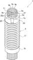
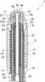
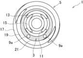
図1は、本発明の実施例1に係る屈曲構造体を示す斜視図、図2は、同一部を断面にした斜視断面図、図3は、屈曲構造体の端部部材を省略した平面図、図4は、屈曲構造体の内筒及び外筒を示す断面図である。[Bent structure]
FIG. 1 is an oblique view showing a bending structure according to a first embodiment of the present invention, FIG. 2 is an oblique cross-sectional view of the same part, FIG. 3 is a plan view of the bending structure with the end members omitted, and FIG. 4 is a cross-sectional view showing the inner tube and outer tube of the bending structure.
本実施例の屈曲構造体1は、マニピュレーター、ロボット、アクチュエーター等の医療用や産業用等の各種の機器の関節機能部に適用されるものであり、屈曲・伸展動作によって両側に結合された機器側部材を相対的に変位可能とする。The
この屈曲構造体1は、内筒3と、外筒5と、端部部材7a,7bと、索状部材としての駆動用ワイヤー9a及びガイド用ワイヤー9bと、可撓部材としての可撓チューブ11を備えている。This
内筒3は、軸方向に対して弾性的に屈曲及び復元可能な二重コイルであり、第1外コイル部13と、第1内コイル部15とを備えている。The
第1外コイル部13及び第1内コイル部15は、それぞれ弾性を有するコイルばねからなる。第1外コイル部13及び第1内コイル部15の材質は、いずれも金属や樹脂等とすることが可能である。また、第1外コイル部13及び第1内コイル部15の素線の断面形状は、円形となっている。ただし、この断面形状は、円形に限られるものではなく、半円や楕円等とすることも可能である。また、第1内外コイル部13及び15の断面形状、線径、材質等は相互に異なってもよい。The first
第1内コイル部15は、第1外コイル部13よりも小さい中心径を有し、第1外コイル部13内に螺合されている。なお、第1外コイル部13及び第1内コイル部15の中心径は、軸方向の一端から他端に至るまで一定となっている。ただし、この第1外コイル部13の中心径は、軸方向で変化させることも可能である。The first
第1外コイル部13は、軸方向で隣接する巻部13a間(隣接巻部13a間)を軸方向で離間させた複数の隙間としてのピッチ13bを有している。この複数のピッチ13bには、第1内コイル部15の対応する巻部15aが内側から嵌合している。この嵌合により、第1内コイル部15の巻部15aは、隣接する第1外コイル部13の巻部13aの双方に接触する。The first
一方、第1内コイル部15は、軸方向で隣接する巻部15a間(隣接巻部15a間)を軸方向で離間させた複数の隙間としてのピッチ15bを有している。この複数のピッチ15bには、第1外コイル部13の対応する巻部13aが外側から嵌合している。この嵌合により、第1外コイル部13の巻部13aは、隣接する第1内コイル部15の巻部15aの双方に接触する。On the other hand, the first
従って、内筒3は、軸方向の圧縮が規制されている。Therefore, the compression of the
外筒5は、内筒3と同様、軸方向に対して弾性的に屈曲及び復元自在な二重コイルであり、第2外コイル部17と、第2内コイル部19とを備えている。この外筒5は、内筒3の外周を隙間21を有して覆っている。なお、外筒5は、内筒3よりも短い場合、内筒3を軸方向で部分的に覆うことになる。このため、外筒5は、少なくとも内筒3の外周の一部を隙間21を有して覆う構成であればよい。The
隙間21は、径方向での外筒5の第2内コイル部19と内筒3の第1外コイル部13との間に区画されている。隙間21の径方向の寸法は、駆動用ワイヤー9a及びガイド用ワイヤー9bの線径より僅かに大きく設定されている。The
これにより、内筒3及び外筒5は、駆動用ワイヤー9a及びガイド用ワイヤー9bのガイドとしての役割を果たす。なお、隙間21の径方向の寸法は、駆動用ワイヤー9a及びガイド用ワイヤー9bのガイドとしての機能を確保する範囲で適宜設定すればよい。As a result, the
外筒5の第2外コイル部17及び第2内コイル部19は、内筒3の第1外コイル部13及び第1内コイル部15と同様に構成されている。ただし、外筒5は、巻方向を内筒3の巻方向と同一又は逆の何れとしてもよい。The second
内筒3及び外筒5の巻方向を逆(逆巻)にする場合は、内筒3及び外筒5がそれぞれ逆向きの捩じりに抗することができ、屈曲構造体1全体としての捩じり剛性を向上することができる。When the winding directions of the
内筒3の第1外コイル部13及び第1内コイル部15と同様、第2外コイル部17及び第2内コイル部19は、弾性を有するコイルばねからなり、金属や樹脂等によって形成することが可能である。第2外コイル部17及び第2内コイル部19の素線の断面形状は、円形であるが、円形に限られるものではない。また、第2内外コイル部19及び17の断面形状、材質、線径等は相互に異なってもよい。Like the first
第2内コイル部19は、第2外コイル部17よりも小さい中心径を有し、第2外コイル部17内に螺合されている。第2外コイル部17及び第2内コイル部19の中心径は、軸方向の一端から他端に至るまで一定となっているが、軸方向で変化させることも可能である。The second
第2外コイル部17は、軸方向で隣接する巻部17a間(隣接巻部17a間)を軸方向で離間させた複数のピッチ17bを有し、この複数のピッチ17bには、第2内コイル部19の対応する巻部19aが内側から嵌合している。この嵌合により、第2内コイル部19の巻部19aは、隣接する第2外コイル部17の巻部17aの双方に接触する。The second
一方、第2内コイル部19は、軸方向で隣接する巻部19a間(隣接巻部19a間)を軸方向で離間させた複数の隙間としてのピッチ19bを有している。この複数のピッチ19bには、第2外コイル部17の対応する巻部17aが外側から嵌合している。この嵌合により、第2外コイル部17の巻部17aは、隣接する第2内コイル部19の巻部19aの双方に接触する。On the other hand, the second
これにより、外筒5は、軸方向の圧縮が規制されている。This restricts the compression of the
端部部材7a,7bは、金属等からなる円柱状である。なお、端部部材7a,7bは、角柱状等の他の形状としてもよい。これら端部部材7a,7bは、それぞれ外筒5の軸方向の端部に溶接等の適宜の固着方法によって取り付けられている。また、端部部材7a,7bは、内筒3の軸方向の端部に取り付けたり、或いは内筒3及び外筒5の双方の軸方向の端部に取り付けてもよい。The
端部部材7a,7bの外筒5への取付けは、第2内外コイル部19,17の何れか一方に対して行われる。本実施例では、第2外コイル部17に対して端部部材7a,7bが取り付けられている。The
この端部部材7a,7bには、第1挿通孔23及び第2挿通孔25が軸方向に貫通して設けられている。第1挿通孔23は、内外筒3,5間の隙間21に軸方向で連通し、駆動用ワイヤー9a及びガイド用ワイヤー9bを挿通する。The
第2挿通孔25は、内筒3の内部に軸方向で連通し、可撓チューブ11を挿通する。本実施例の第2挿通孔25は、端部部材7a,7bの軸心部に設けられ、断面円形に形成されている。The
かかる端部部材7a,7bは、屈曲構造体1を介して相対的に変位する機器側部材にそれぞれ取り付けられる。例えば、一方の端部部材7aは、先端側の機器側部材、他方の端部部材7bは、基端側の機器側部材に取り付けられる。これら端部部材7a,7bは、省略することも可能である。この場合、外筒5の両端を機器側部材に直接取り付ければよい。These
駆動用ワイヤー9a及びガイド用ワイヤー9bは、金属等からなる駆動用索状部材及びガイド用索状部材である。駆動用ワイヤー9a及びガイド用ワイヤー9bは、屈曲構造体1の屈曲及び復元を妨げない程度の柔軟性を有している。The
駆動用ワイヤー9a及びガイド用ワイヤー9bの断面形状は、第1挿通孔23と同様の円形とする他、楕円形や矩形等の異なる形状としてもよい。駆動用ワイヤー9a及びガイド用ワイヤー9bは、索状部材であれば、撚り線、NiTi(ニッケルチタン)単線、ピアノ線、多関節ロッド、鎖、紐、糸、縄等とすることが可能である。The cross-sectional shape of the
なお、ガイド用ワイヤー9bは、金属等に限らず、樹脂によって形成してもよい。さらに、ガイド用ワイヤー9bは、索状部材とせずに、柱状や棒状の部材とすることも可能である。The
かかる駆動用ワイヤー9a及びガイド用ワイヤー9bは、内外筒3,5間の隙間21を軸方向に挿通してガイドされている。本実施例において、駆動用ワイヤー9a及びガイド用ワイヤー9bは、周方向の所定間隔毎に複数設けられている。なお、駆動用ワイヤー9aは、軸方向に沿って直状にガイドされる他、軸周りに螺旋状にガイドされてもよい。The
駆動用ワイヤー9a及びガイド用ワイヤー9bの端部27は、端部部材7a,7bの第1挿通孔23を挿通して外部に引き出されている。一方の端部部材7aから引き出された端部27は、端部処理によって抜け止めされている。The ends 27 of the
駆動用ワイヤー9aは、一方の端部部材7aに対して他方の端部部材7bを駆動可能とする。すなわち、駆動用ワイヤー9aは、軸方向に引かれることによって屈曲構造体1を屈曲させるものであり、直接又は間接的に図示しない操作機構に接続され、軸方向に操作されるようになっている。The
なお、軸方向に操作とは、軸方向で駆動用ワイヤー9aを進退させることを意味する。駆動用ワイヤー9aの数は、屈曲構造体1の屈曲動作に応じて適宜設定することが可能である。Note that operating in the axial direction means moving the
ガイド用ワイヤー9bは、各駆動用ワイヤー9aの周方向の両側に設けられ、駆動用ワイヤー9aの経路を限定する。ガイド用ワイヤー9bは、駆動用ワイヤー9aの周方向へのズレを規制する。本実施例では、ガイド用ワイヤー9b及び駆動用ワイヤー9aが相互に周方向へのズレを規制することで、結果として駆動用ワイヤー9aの経路を限定している。The
なお、ガイド用ワイヤー9bは、駆動用ワイヤー9aとして機能させることも可能である。また、ガイド用ワイヤー9bは、省略することも可能である。さらに、駆動用ワイヤー9a及びガイド用ワイヤー9bの一方又は双方は、通電経路として用いることも可能である。なお、通電経路としては、内筒3を用いることも可能である。The
可撓チューブ11は、樹脂等によって形成された筒状部材であり、内筒3の第1内コイル部15内を挿通している。この可撓チューブ11は、屈曲構造体1の屈曲及び復元を妨げない程度の柔軟性を有している。可撓チューブ11の端部は、端部部材7a,7bの第2挿通孔25を挿通して外部に引き出されている。また、索状部材としては、駆動用及びガイド用を設けずに、通電用のもののみを設けてもよい。The
この可撓チューブ11は、端部において第2挿通孔25に嵌合している。これにより、端部部材7a,7bに対して可撓チューブ11を介して内筒3が位置決められる。なお、位置決めの基準は、端部部材7a及び7bの一方とすればよい。端部部材7a,7bには、外筒5が取り付けられて位置決められている。The
従って、本実施例では、端部部材7a,7bにより内外筒3,5間が位置決められ、駆動用ワイヤー9a及びガイド用ワイヤー9bを挿通する隙間21が正確に区画されている。Therefore, in this embodiment, the
可撓チューブ11の内側には、エンドエフェクタ等の駆動するためのエアチューブやプッシュプルケーブル等の駆動部材が挿通される。なお、可撓チューブ11を省略して、エアチューブやプッシュプルケーブル等の駆動部材や他の可撓性を有する部材を可撓部材としてもよい。可撓チューブ11や駆動部材等の可撓部材自体を省略してもよい。Driving members such as an air tube or a push-pull cable for driving an end effector or the like are inserted inside the
[動作]
図5は、屈曲時の内筒3を示す断面図である。なお、外筒5の屈曲は、内筒3の屈曲と同様であるため、図5を参照する。このため、図5では、外筒5の符号を括弧書きで示す。[motion]
Fig. 5 is a cross-sectional view showing the
本実施例の屈曲構造体1は、図4のように、屈曲していない直状時(伸展時)において、内筒3の第1外コイル部13の隣接巻部13a間に第1内コイル部15の対応する巻部15aが嵌合している。外筒5も、第2外コイル部17の隣接巻部17a間に第2内コイル部19の対応する巻部19aが嵌合している。When the
このため、屈曲構造体1では、軸方向での圧縮力が作用しても、内筒3の第1内外コイル部15,13及び外筒5の第2内外コイル部19,17の圧縮が防止され、全体としての圧縮も防止される。このように圧縮が防止されることにより、中心部の長さが変わらずに姿勢が安定する。For this reason, in the
また、内筒3及び外筒5が逆巻の場合は、内筒3及び外筒5のそれぞれが逆向きの捩じりに抗することができる。このため、捩じり方向の力が作用しても、全体としての捩じりが抑制されて姿勢が安定する。In addition, when the
このように屈曲構造体1は、耐圧縮性や耐捩じり性が高く、姿勢が安定するので、安定した内筒3及び外筒5間の隙間21を得ることができ、駆動用ワイヤー9a及びガイド用ワイヤー9bを隙間21により確実にガイドできる。In this way, the bending
この屈曲構造体1は、操作者が何れか一つの駆動用ワイヤー9aを引くことによって屈曲し、異なる対の駆動用ワイヤー9aを組み合わせて引くことによって360度全方位に屈曲することが可能となる。この屈曲により、屈曲構造体1が適用された機器であるマニピュレーターのエンドエフェクタ等を所望の方向に指向させることができる。This bending
何れか一つの駆動用ワイヤー9aが引かれると、図5のように、屈曲の内側では、内筒3及び外筒5の第1及び第2外コイル部13,17の隣接巻部13a,17a間のピッチ13b,17bが小さくなり、屈曲の外側では、内筒3及び外筒5の第1及び第2外コイル部13,17の隣接巻部13a,17a間のピッチ13b,17bが大きくなる。これにより、内筒15の中心部の長さは屈曲時も変わらずに姿勢が安定する。When one of the
このとき、内筒3及び外筒5の第1及び第2内コイル部15,19が屈曲の外側へ向けて押し出される。この第1及び第2内コイル部15,19の押出しは、屈曲の外側で内筒3及び外筒5の第1及び第2外コイル部13,17の隣接巻部13a,17a間の大きくなったピッチ13b,17bによって許容される。このため、円滑に屈曲動作を行わせることができる。At this time, the first and second
しかも、屈曲時には、内筒3及び外筒5の第1及び第2外コイル部13,17の隣接巻部13a,17a間に第1及び第2内コイル部15,19の対応する巻部15a,19aが嵌合し続けている。Moreover, when bent, the corresponding winding
このため、直状時と同様に、屈曲構造体1は、軸方向の圧縮が抑制され、この点からも中心部の長さの変動が抑制され、姿勢が安定する。従って、安定した内筒3及び外筒5間の隙間21を得ることができ、駆動用ワイヤー9a及びガイド用ワイヤー9bが隙間21により確実にガイドされる。As a result, just as when it is straight, the
また、外筒5の第2内コイル部19が押し出される際には、屈曲の内側で内筒3及び外筒5間の隙間21が小さくなり、屈曲の外側で内筒3及び外筒5間の隙間21が大きくなる。In addition, when the second
屈曲後は、内筒3及び外筒5が共に第1及び第2外コイル部13,17の隣接巻部13a,17a間に第1及び第2内コイル部15,19が嵌合した圧縮されていない屈曲前の直状時の状態に確実に戻る。このため、駆動用ワイヤー9a及びガイド用ワイヤー9bが内筒3及び外筒5間の隙間21により屈曲前と同じように確実にガイドされる。After bending, both the
[実施例1の効果]
以上説明したように、本実施例では、第1内コイル部15及び第1外コイル部13からなり、第1外コイル部13の隣接巻部13a間のピッチ13bに第1内コイル部15の対応する巻部15aが嵌合する内筒3と、内筒3の外周を隙間21を有して覆い、第2内コイル部19及び第2外コイル部17からなり、第2外コイル部17の隣接巻部17a間のピッチ17bに第2内コイル部19の対応する巻部19aが嵌合する外筒5と、内筒3及び外筒5間の隙間21を軸方向に挿通してガイドされる周方向に複数の駆動用ワイヤー9a及びガイド用ワイヤー9bと、を備えた。[Effects of Example 1]
As described above, this embodiment includes an
従って、本実施例では、内外コイル部13,15,17,19からなる内筒3及び外筒5間の隙間21に駆動用ワイヤー9a及びガイド用ワイヤー9bを配置するだけで、駆動用ワイヤー9aの操作で屈曲復元が可能な屈曲構造体1を簡単な構造で実現できる。Therefore, in this embodiment, by simply placing the
しかも、本実施例の屈曲構造体1では、屈曲前後で内筒3及び外筒5の圧縮を防止できる。このため、内筒3及び外筒5間の隙間21を介して駆動用ワイヤー9a及びガイド用ワイヤー9bを確実にガイドすることができ、駆動用ワイヤー9aの操作に基づく動作を安定させることができる。Moreover, in the bending
また、本実施例の屈曲構造体1は、外筒5の両端に取り付けられ、駆動用ワイヤー9a及びガイド用ワイヤー9bをそれぞれ第1挿通孔23に挿通する端部部材7a,7bを備えている。The bending
このため、屈曲構造体1は、両端において駆動用ワイヤー9a及びガイド用ワイヤー9b間を位置決めることができ、より確実に駆動用ワイヤー9a及びガイド用ワイヤー9bをガイドすることができる。As a result, the bending
また、本実施例の屈曲構造体1は、内筒3の第1内コイル部15内を挿通する可撓チューブ11を備え、端部部材7a,7bが軸心部に可撓チューブ11を挿通する第2挿通孔25を有する。The
従って、本実施例では、内筒3の第1内コイル部15内を可撓チューブ11を挿通する経路として利用できる。しかも、可撓チューブ11を介して端部部材7a,7bに内筒3が位置決められ、且つ端部部材7a,7bに外筒5が取り付けによって位置決められるため、内外筒3,5間を確実に位置決めて屈曲動作を円滑に行うことができる。しかも、内外筒3,5間の隙間21を正確に区画でき、より確実に駆動用ワイヤー9a及びガイド用ワイヤー9bをガイドすることができる。Therefore, in this embodiment, the inside of the first
また、本実施例では、内筒3の第1内外コイル部15,13と外筒5の第2内外コイル部19,17とが相互に逆巻きである場合、内筒3及び外筒5とで異なる方向の捩じりに抗することができ、全体としての捩じり剛性を向上できる。In addition, in this embodiment, when the first inner and
図6は、本発明の実施例2に係る屈曲構造体の端部部材を省略した平面図である。なお、実施例2では、実施例1と対応する構成に同符号を付して重複した説明を省略する。Figure 6 is a plan view of a bent structure according to a second embodiment of the present invention, with the end members omitted. In the second embodiment, the same reference numerals are used to designate components corresponding to those in the first embodiment, and redundant explanations are omitted.
実施例2では、内筒3及び外筒5の中心をずらしたものである。その他は実施例1と同一である。In Example 2, the centers of the
本実施例では、内筒3及び外筒5の中心O及びO’をずらしたことで、ずらし方向の一方で隙間21が他方よりも狭くなっている。このずらし方向の一方での隙間21は、駆動用ワイヤー9aを配置できない程度まで狭くなっている。そして、ずらし方向の他方側の隙間21にのみ、駆動用ワイヤー9aを配置している。In this embodiment, by shifting the centers O and O' of the
従って、実施例2では、駆動用ワイヤー9aを省略したことで小型化(小径化)を図ることができる。その他、実施例2でも、実施例1と同様の作用効果を奏することができる。Therefore, in Example 2, the
1 屈曲構造体
3 内筒
5 外筒
7a,7b 端部部材
9a 駆動用ワイヤー(索状部材)
9b ガイド用ワイヤー(索状部材)
11 可撓チューブ(可撓部材)
13 第1外コイル部
13a 巻部
15 第1内コイル部
15a 巻部
17 第2外コイル部
17a 巻部
19 第2内コイル部
19a 巻部
21 隙間
23 第1挿通孔
25 第2挿通孔
1
9b Guide wire (cord-like member)
11 Flexible tube (flexible member)
13 First
Claims (2)
Translated fromJapanese前記筒の両端にそれぞれ軸方向で当接した状態で取り付けられた端部部材と、を備え、
前記端部部材は、前記内外コイル部の何れか一方に対して取り付けられた、
屈曲構造体。 a tube including an inner coil portion and an outer coil portion, in which adjacent winding portions of the outer coil portion are fitted into corresponding gaps between the adjacent winding portions of the inner coil portion;
end members attached to both ends of the tube in an axial abutting relationship,
The end member is attached to either one of the inner and outer coil portions.
Bending structure.
前記端部部材は、前記外コイル部に対して取り付けられた、
屈曲構造体。
2. The bent structure of claim 1,
The end memberis attached to the outer coil portion.
Bending structure.
Priority Applications (1)
| Application Number | Priority Date | Filing Date | Title |
|---|---|---|---|
| JP2023122872AJP7526326B2 (en) | 2020-10-30 | 2023-07-27 | Bent Structure |
Applications Claiming Priority (2)
| Application Number | Priority Date | Filing Date | Title |
|---|---|---|---|
| JP2020183190AJP7587962B2 (en) | 2020-10-30 | 2020-10-30 | Bent Structure |
| JP2023122872AJP7526326B2 (en) | 2020-10-30 | 2023-07-27 | Bent Structure |
Related Parent Applications (1)
| Application Number | Title | Priority Date | Filing Date |
|---|---|---|---|
| JP2020183190ADivisionJP7587962B2 (en) | 2020-10-30 | 2020-10-30 | Bent Structure |
Publications (2)
| Publication Number | Publication Date |
|---|---|
| JP2023153902A JP2023153902A (en) | 2023-10-18 |
| JP7526326B2true JP7526326B2 (en) | 2024-07-31 |
Family
ID=81384037
Family Applications (2)
| Application Number | Title | Priority Date | Filing Date |
|---|---|---|---|
| JP2020183190AActiveJP7587962B2 (en) | 2020-10-30 | 2020-10-30 | Bent Structure |
| JP2023122872AActiveJP7526326B2 (en) | 2020-10-30 | 2023-07-27 | Bent Structure |
Family Applications Before (1)
| Application Number | Title | Priority Date | Filing Date |
|---|---|---|---|
| JP2020183190AActiveJP7587962B2 (en) | 2020-10-30 | 2020-10-30 | Bent Structure |
Country Status (6)
| Country | Link |
|---|---|
| US (1) | US12296467B2 (en) |
| EP (1) | EP4238723B1 (en) |
| JP (2) | JP7587962B2 (en) |
| CN (1) | CN116457163A (en) |
| TW (1) | TWI792642B (en) |
| WO (1) | WO2022092268A1 (en) |
Citations (1)
| Publication number | Priority date | Publication date | Assignee | Title |
|---|---|---|---|---|
| JP2020026019A (en) | 2018-08-14 | 2020-02-20 | 日本発條株式会社 | Instruments for surgery support robots |
Family Cites Families (14)
| Publication number | Priority date | Publication date | Assignee | Title |
|---|---|---|---|---|
| US5154705A (en)* | 1987-09-30 | 1992-10-13 | Lake Region Manufacturing Co., Inc. | Hollow lumen cable apparatus |
| US5271543A (en)* | 1992-02-07 | 1993-12-21 | Ethicon, Inc. | Surgical anastomosis stapling instrument with flexible support shaft and anvil adjusting mechanism |
| US5405073A (en)* | 1993-12-06 | 1995-04-11 | Ethicon, Inc. | Flexible support shaft assembly |
| US5465894A (en)* | 1993-12-06 | 1995-11-14 | Ethicon, Inc. | Surgical stapling instrument with articulated stapling head assembly on rotatable and flexible support shaft |
| US5762995A (en)* | 1995-01-13 | 1998-06-09 | Fuji Photo Optical Co., Ltd. | Flexible sheathing tube construction, and method for fabrication thereof |
| US5851212A (en)* | 1997-06-11 | 1998-12-22 | Endius Incorporated | Surgical instrument |
| JPH1170488A (en)* | 1997-08-28 | 1999-03-16 | Fujitsu Ltd | Flexible bending drive module |
| GB0020461D0 (en) | 2000-08-18 | 2000-10-11 | Oliver Crispin Consulting Ltd | Improvements in and relating to the robotic positioning of a work tool to a sensor |
| US6790173B2 (en)* | 2002-06-13 | 2004-09-14 | Usgi Medical, Inc. | Shape lockable apparatus and method for advancing an instrument through unsupported anatomy |
| US7422559B2 (en)* | 2004-06-16 | 2008-09-09 | Ge Inspection Technologies, Lp | Borescope comprising fluid supply system |
| GB0600170D0 (en)* | 2006-01-06 | 2006-02-15 | Oliver Crispin Robotics Ltd | Improvements in and relating to robotic arms |
| US8105350B2 (en) | 2006-05-23 | 2012-01-31 | Cambridge Endoscopic Devices, Inc. | Surgical instrument |
| KR20230056068A (en)* | 2014-02-21 | 2023-04-26 | 인튜어티브 서지컬 오퍼레이션즈 인코포레이티드 | Articulatable members having constrained motion, and related devices and methods |
| US11226138B2 (en)* | 2017-11-15 | 2022-01-18 | Thermolift, Inc. | Thermodynamic device with a tension-compression coil spring system |
- 2020
- 2020-10-30JPJP2020183190Apatent/JP7587962B2/enactiveActive
- 2021
- 2021-10-29TWTW110140205Apatent/TWI792642B/enactive
- 2021-10-29CNCN202180072498.0Apatent/CN116457163A/enactivePending
- 2021-10-29USUS18/034,047patent/US12296467B2/enactiveActive
- 2021-10-29EPEP21886385.0Apatent/EP4238723B1/enactiveActive
- 2021-10-29WOPCT/JP2021/040036patent/WO2022092268A1/ennot_activeCeased
- 2023
- 2023-07-27JPJP2023122872Apatent/JP7526326B2/enactiveActive
Patent Citations (1)
| Publication number | Priority date | Publication date | Assignee | Title |
|---|---|---|---|---|
| JP2020026019A (en) | 2018-08-14 | 2020-02-20 | 日本発條株式会社 | Instruments for surgery support robots |
Also Published As
| Publication number | Publication date |
|---|---|
| JP7587962B2 (en) | 2024-11-21 |
| EP4238723A1 (en) | 2023-09-06 |
| JP2023153902A (en) | 2023-10-18 |
| EP4238723A4 (en) | 2024-05-01 |
| TWI792642B (en) | 2023-02-11 |
| US20230330871A1 (en) | 2023-10-19 |
| CN116457163A (en) | 2023-07-18 |
| EP4238723B1 (en) | 2025-08-13 |
| JP2022073297A (en) | 2022-05-17 |
| WO2022092268A1 (en) | 2022-05-05 |
| US12296467B2 (en) | 2025-05-13 |
| TW202216081A (en) | 2022-05-01 |
Similar Documents
| Publication | Publication Date | Title |
|---|---|---|
| JP7373613B2 (en) | Bending structure and joint function part using the same | |
| JP7538692B2 (en) | Bending operation mechanism | |
| JP7657094B2 (en) | Bent Structure | |
| US20230339124A1 (en) | Bending structure and joint function part | |
| JP7526326B2 (en) | Bent Structure | |
| WO2023008274A1 (en) | Flexible structure | |
| JP7498611B2 (en) | Joint function area | |
| JP7565826B2 (en) | Bent Structure | |
| JP7701848B2 (en) | bending structure | |
| TW202417207A (en) | Flexible structure capable of locally varying the bending rigidity in the axial direction by means of a simple structure |
Legal Events
| Date | Code | Title | Description |
|---|---|---|---|
| A621 | Written request for application examination | Free format text:JAPANESE INTERMEDIATE CODE: A621 Effective date:20231011 | |
| A131 | Notification of reasons for refusal | Free format text:JAPANESE INTERMEDIATE CODE: A131 Effective date:20240206 | |
| A601 | Written request for extension of time | Free format text:JAPANESE INTERMEDIATE CODE: A601 Effective date:20240403 | |
| A521 | Request for written amendment filed | Free format text:JAPANESE INTERMEDIATE CODE: A523 Effective date:20240531 | |
| TRDD | Decision of grant or rejection written | ||
| A01 | Written decision to grant a patent or to grant a registration (utility model) | Free format text:JAPANESE INTERMEDIATE CODE: A01 Effective date:20240702 | |
| A61 | First payment of annual fees (during grant procedure) | Free format text:JAPANESE INTERMEDIATE CODE: A61 Effective date:20240719 | |
| R150 | Certificate of patent or registration of utility model | Ref document number:7526326 Country of ref document:JP Free format text:JAPANESE INTERMEDIATE CODE: R150 |