JP7524268B2 - System for pairing a medical system with a network controller by using a dongle - Patents.com - Google Patents
System for pairing a medical system with a network controller by using a dongle - Patents.comDownload PDFInfo
- Publication number
- JP7524268B2 JP7524268B2JP2022164141AJP2022164141AJP7524268B2JP 7524268 B2JP7524268 B2JP 7524268B2JP 2022164141 AJP2022164141 AJP 2022164141AJP 2022164141 AJP2022164141 AJP 2022164141AJP 7524268 B2JP7524268 B2JP 7524268B2
- Authority
- JP
- Japan
- Prior art keywords
- medical
- data
- patient
- hub
- dongle
- Prior art date
- Legal status (The legal status is an assumption and is not a legal conclusion. Google has not performed a legal analysis and makes no representation as to the accuracy of the status listed.)
- Active
Links
Images


Classifications
- A—HUMAN NECESSITIES
- A61—MEDICAL OR VETERINARY SCIENCE; HYGIENE
- A61B—DIAGNOSIS; SURGERY; IDENTIFICATION
- A61B5/00—Measuring for diagnostic purposes; Identification of persons
- A61B5/145—Measuring characteristics of blood in vivo, e.g. gas concentration or pH-value ; Measuring characteristics of body fluids or tissues, e.g. interstitial fluid or cerebral tissue
- A61B5/1455—Measuring characteristics of blood in vivo, e.g. gas concentration or pH-value ; Measuring characteristics of body fluids or tissues, e.g. interstitial fluid or cerebral tissue using optical sensors, e.g. spectral photometrical oximeters
- A61B5/14551—Measuring characteristics of blood in vivo, e.g. gas concentration or pH-value ; Measuring characteristics of body fluids or tissues, e.g. interstitial fluid or cerebral tissue using optical sensors, e.g. spectral photometrical oximeters for measuring blood gases
- A61B5/14552—Details of sensors specially adapted therefor
- G—PHYSICS
- G06—COMPUTING OR CALCULATING; COUNTING
- G06F—ELECTRIC DIGITAL DATA PROCESSING
- G06F13/00—Interconnection of, or transfer of information or other signals between, memories, input/output devices or central processing units
- G06F13/38—Information transfer, e.g. on bus
- G06F13/382—Information transfer, e.g. on bus using universal interface adapter
- G06F13/385—Information transfer, e.g. on bus using universal interface adapter for adaptation of a particular data processing system to different peripheral devices
- G—PHYSICS
- G06—COMPUTING OR CALCULATING; COUNTING
- G06F—ELECTRIC DIGITAL DATA PROCESSING
- G06F13/00—Interconnection of, or transfer of information or other signals between, memories, input/output devices or central processing units
- G06F13/38—Information transfer, e.g. on bus
- G06F13/40—Bus structure
- G06F13/4004—Coupling between buses
- G—PHYSICS
- G06—COMPUTING OR CALCULATING; COUNTING
- G06F—ELECTRIC DIGITAL DATA PROCESSING
- G06F13/00—Interconnection of, or transfer of information or other signals between, memories, input/output devices or central processing units
- G06F13/38—Information transfer, e.g. on bus
- G06F13/42—Bus transfer protocol, e.g. handshake; Synchronisation
- G06F13/4282—Bus transfer protocol, e.g. handshake; Synchronisation on a serial bus, e.g. I2C bus, SPI bus
- G—PHYSICS
- G16—INFORMATION AND COMMUNICATION TECHNOLOGY [ICT] SPECIALLY ADAPTED FOR SPECIFIC APPLICATION FIELDS
- G16H—HEALTHCARE INFORMATICS, i.e. INFORMATION AND COMMUNICATION TECHNOLOGY [ICT] SPECIALLY ADAPTED FOR THE HANDLING OR PROCESSING OF MEDICAL OR HEALTHCARE DATA
- G16H10/00—ICT specially adapted for the handling or processing of patient-related medical or healthcare data
- G16H10/60—ICT specially adapted for the handling or processing of patient-related medical or healthcare data for patient-specific data, e.g. for electronic patient records
- G—PHYSICS
- G16—INFORMATION AND COMMUNICATION TECHNOLOGY [ICT] SPECIALLY ADAPTED FOR SPECIFIC APPLICATION FIELDS
- G16H—HEALTHCARE INFORMATICS, i.e. INFORMATION AND COMMUNICATION TECHNOLOGY [ICT] SPECIALLY ADAPTED FOR THE HANDLING OR PROCESSING OF MEDICAL OR HEALTHCARE DATA
- G16H40/00—ICT specially adapted for the management or administration of healthcare resources or facilities; ICT specially adapted for the management or operation of medical equipment or devices
- G16H40/40—ICT specially adapted for the management or administration of healthcare resources or facilities; ICT specially adapted for the management or operation of medical equipment or devices for the management of medical equipment or devices, e.g. scheduling maintenance or upgrades
- G—PHYSICS
- G16—INFORMATION AND COMMUNICATION TECHNOLOGY [ICT] SPECIALLY ADAPTED FOR SPECIFIC APPLICATION FIELDS
- G16H—HEALTHCARE INFORMATICS, i.e. INFORMATION AND COMMUNICATION TECHNOLOGY [ICT] SPECIALLY ADAPTED FOR THE HANDLING OR PROCESSING OF MEDICAL OR HEALTHCARE DATA
- G16H40/00—ICT specially adapted for the management or administration of healthcare resources or facilities; ICT specially adapted for the management or operation of medical equipment or devices
- G16H40/60—ICT specially adapted for the management or administration of healthcare resources or facilities; ICT specially adapted for the management or operation of medical equipment or devices for the operation of medical equipment or devices
- G16H40/63—ICT specially adapted for the management or administration of healthcare resources or facilities; ICT specially adapted for the management or operation of medical equipment or devices for the operation of medical equipment or devices for local operation
- G—PHYSICS
- G16—INFORMATION AND COMMUNICATION TECHNOLOGY [ICT] SPECIALLY ADAPTED FOR SPECIFIC APPLICATION FIELDS
- G16H—HEALTHCARE INFORMATICS, i.e. INFORMATION AND COMMUNICATION TECHNOLOGY [ICT] SPECIALLY ADAPTED FOR THE HANDLING OR PROCESSING OF MEDICAL OR HEALTHCARE DATA
- G16H40/00—ICT specially adapted for the management or administration of healthcare resources or facilities; ICT specially adapted for the management or operation of medical equipment or devices
- G16H40/60—ICT specially adapted for the management or administration of healthcare resources or facilities; ICT specially adapted for the management or operation of medical equipment or devices for the operation of medical equipment or devices
- G16H40/67—ICT specially adapted for the management or administration of healthcare resources or facilities; ICT specially adapted for the management or operation of medical equipment or devices for the operation of medical equipment or devices for remote operation
- H—ELECTRICITY
- H04—ELECTRIC COMMUNICATION TECHNIQUE
- H04L—TRANSMISSION OF DIGITAL INFORMATION, e.g. TELEGRAPHIC COMMUNICATION
- H04L67/00—Network arrangements or protocols for supporting network services or applications
- H04L67/01—Protocols
- H04L67/12—Protocols specially adapted for proprietary or special-purpose networking environments, e.g. medical networks, sensor networks, networks in vehicles or remote metering networks
- H—ELECTRICITY
- H04—ELECTRIC COMMUNICATION TECHNIQUE
- H04W—WIRELESS COMMUNICATION NETWORKS
- H04W4/00—Services specially adapted for wireless communication networks; Facilities therefor
- H04W4/30—Services specially adapted for particular environments, situations or purposes
- H04W4/38—Services specially adapted for particular environments, situations or purposes for collecting sensor information
- H—ELECTRICITY
- H04—ELECTRIC COMMUNICATION TECHNIQUE
- H04W—WIRELESS COMMUNICATION NETWORKS
- H04W4/00—Services specially adapted for wireless communication networks; Facilities therefor
- H04W4/70—Services for machine-to-machine communication [M2M] or machine type communication [MTC]
Landscapes
- Engineering & Computer Science (AREA)
- Health & Medical Sciences (AREA)
- Biomedical Technology (AREA)
- Theoretical Computer Science (AREA)
- Physics & Mathematics (AREA)
- General Health & Medical Sciences (AREA)
- Medical Informatics (AREA)
- Public Health (AREA)
- General Business, Economics & Management (AREA)
- Business, Economics & Management (AREA)
- General Engineering & Computer Science (AREA)
- Primary Health Care (AREA)
- Epidemiology (AREA)
- General Physics & Mathematics (AREA)
- Life Sciences & Earth Sciences (AREA)
- Computer Hardware Design (AREA)
- Spectroscopy & Molecular Physics (AREA)
- Optics & Photonics (AREA)
- Surgery (AREA)
- Molecular Biology (AREA)
- Heart & Thoracic Surgery (AREA)
- Pathology (AREA)
- Animal Behavior & Ethology (AREA)
- Biophysics (AREA)
- Veterinary Medicine (AREA)
- Computer Networks & Wireless Communication (AREA)
- Signal Processing (AREA)
- Computing Systems (AREA)
- Measuring And Recording Apparatus For Diagnosis (AREA)
- Medical Treatment And Welfare Office Work (AREA)
- Measurement Of The Respiration, Hearing Ability, Form, And Blood Characteristics Of Living Organisms (AREA)
- Mobile Radio Communication Systems (AREA)
Description
Translated fromJapanese関連出願
本出願は、次の米国特許出願に関係し、その開示は全体が参照により本明細書に組み込まれる。
出願番号
出願日
名称
整理番号
62/463,452
2017年2月24日
患者モニタ通信プラットフォーム
MAS.1126PR
62/463,297
2017年2月24日
モジュール式マルチパラメータ患者監視デバイス
MAS.1130PR
62/463,517
2017年2月24日
医療監視データを表示し制御するためのシステム
MAS.1132PR1
62/503,109
2017年5月8日
医療監視データを表示し制御するためのシステム
MAS.1170PR1
62/535,757
2017年7月21日
医療監視データを表示し制御するためのシステム
MAS.1170PR2
62/463,614
2017年2月25日
患者モニタ通信プラットフォーム
MAS.1133PRRELATED APPLICATIONS This application is related to the following U.S. patent applications, the disclosures of which are incorporated herein by reference in their entireties:
Application number Application date Name Serial number
62/463,452
February 24, 2017Patient Monitor Communication Platform
MAS.1126PR
62/463,297
February 24, 2017Modular multi-parameter patient monitoring device
MAS.1130PR
62/463,517
February 24, 2017System for displaying and controlling medical monitoring data
MAS.1132PR1
62/503,109
May 8, 2017System for displaying and controlling medical monitoring data
MAS.1170PR1
62/535,757
July 21, 2017System for displaying and controlling medical monitoring data
MAS.1170PR2
62/463,614
February 25, 2017Patient Monitor Communication Platform
MAS.1133PR
本明細書において説明されている実施形態の多くは、上記の関連出願において説明されている実施形態に適合している。さらに、本明細書において説明されている特徴の一部または全部は、上に列挙されている出願において説明されている特徴の多くとともに使用されるか、または他の何らかの形で組み合わされ得る。Many of the embodiments described herein are compatible with the embodiments described in the related applications listed above. Furthermore, some or all of the features described herein may be used or otherwise combined with many of the features described in the applications listed above.
本開示は、一般的に患者監視デバイスに関し、詳細には患者モニタおよび医療データ通信ハブ(medical data communication hub)に関するものである。The present disclosure relates generally to patient monitoring devices, and more particularly to patient monitors and medical data communication hubs.
今日の患者監視環境は、所与の患者に対する多種多様の監視および治療活動を提供する高度な、多くの場合に電子的な医療用デバイス(medical device)で賑わっている。一般的に、これらのデバイスはすべてではないとしてもその多くが異なるメーカーからのものであり、多くは携帯型デバイスであり得る。これらのデバイスは互いに通信し得ず、各々その専用の制御、表示、アラーム、構成、および同様のものを備え得る。問題を複雑にしているのは、多くの場合に介護人がこれらのデバイスからのすべての種類の測定および使用データを特定の患者に関連付けることを望んでいることである。したがって、患者情報入力は、デバイス毎に行われることが多い。ときには、デバイス内の不一致のせいで、介護人が再検討できるように各デバイスから単に紙に印刷し患者のカルテに保管する必要が生じる。Today's patient monitoring environment is bustling with sophisticated, often electronic, medical devices that provide a wide variety of monitoring and treatment activities for a given patient. Typically, many, if not all, of these devices are from different manufacturers, and many may be portable devices. These devices may not communicate with each other, and each may have its own dedicated controls, displays, alarms, configurations, and the like. Complicating the issue is that caregivers often want all kinds of measurement and usage data from these devices to be associated with a specific patient. Thus, patient information entry is often done on a device-by-device basis. Sometimes, inconsistencies within devices necessitate simply printing out a paper copy from each device and filing it in the patient's chart for review by the caregiver.
デバイスのそのような相違の結果、多くの場合に、介護人環境内に複数のディスプレイとアラームが散らばり、潜在的にカオス的な体験をすることになる。そのようなカオスは、介護人の注意散漫が望ましくない外科的環境を含む、および患者の注意散漫もしくは混乱が望ましくない場合のある回復または監視環境を含む多くの状況において患者にとって有害であり得る。Such differences in devices often result in a caregiver's environment being cluttered with multiple displays and alarms, creating a potentially chaotic experience. Such chaos can be harmful to patients in many situations, including surgical environments where caregiver distraction is undesirable, and recovery or monitoring environments where patient distraction or confusion may be undesirable.
様々なメーカーが、特定のシステムが達成できる監視または治療活動の多様性を高めるためにマルチモニタデバイスまたはモジュール方式で拡張するデバイスを生産している。しかしながら、医療用デバイス技術が拡大するにつれ、そのようなマルチモニタデバイスは、設置された瞬間から陳腐化し始める。Various manufacturers produce multi-monitor devices or devices that expand in a modular fashion to increase the variety of monitoring or treatment activities that a particular system can accomplish. However, as medical device technology expands, such multi-monitor devices begin to become obsolete the moment they are installed.
本開示では、監視されている患者に対する監視の中心としての医療監視ハブの実施形態を説明する。ハブは、患者の近くにある他の医療用デバイスと通信するための構成可能な医療用ポートとシリアルポートとを備えることができる。さらに、ハブは、携帯型患者モニタと通信することができる。モニタは、ハブにドッキングされたときに、ドッキングを解除されたときと異なる表示グラフィックスを提示するものとしてよい。表示グラフィックスは、解剖学的情報を含むことができる。ハブは、多くの場合に膨大な量となる電子医療データをアセンブルし、それを監視される患者に関連付け、いくつかの実施形態において、通信によりデータを患者の医療記録に転送することができる。This disclosure describes embodiments of a medical monitoring hub as a monitoring center for a monitored patient. The hub can include configurable medical and serial ports for communication with other medical devices in the patient's vicinity. Additionally, the hub can communicate with a portable patient monitor. When docked to the hub, the monitor can present different display graphics than when undocked. The display graphics can include anatomical information. The hub can assemble the often-extensive amount of electronic medical data, associate it with the monitored patient, and in some embodiments, communicate the data to the patient's medical record.
本開示のいくつかの態様では、デジタル論理回路を有する第1の医療用デバイスが生理学的センサから患者に関連付けられている生理学的信号を受信し、生理学的信号に基づき第1の生理学的パラメータ値を取得し、第1の生理学的パラメータ値を表示のため出力することを説明している。第1の医療用デバイスは、また、第1の医療用デバイスと異なる第2の医療用デバイスから第2の生理学的パラメータ値を受信することができ、第2の生理学的パラメータ値は、第1の医療用デバイスによって使用されないプロトコルに従ってフォーマットされ、それにより、第1の医療用デバイスは、表示可能な出力値を生成するために第2の生理学的パラメータ値を処理することができない。第1の医療用デバイスは、生理学的パラメータデータを第1の医療用デバイスから別個の翻訳モジュールに受け渡し、翻訳されたパラメータデータを第1の医療用デバイスにおける翻訳モジュールから受信し、翻訳されたパラメータデータは第1の医療用デバイスによる表示のために処理されることが可能であり、翻訳されたパラメータデータからの第2の値を出力し表示することができる。第1の医療用デバイスは、たとえば、監視ハブ、携帯型生理学的モニタ、または複数患者監視システムであってよく、第2の医療用デバイスは、輸液ポンプ、換気装置、または同様のものであってよい。Some aspects of the present disclosure describe a first medical device having a digital logic circuit receiving a physiological signal associated with a patient from a physiological sensor, obtaining a first physiological parameter value based on the physiological signal, and outputting the first physiological parameter value for display. The first medical device can also receive a second physiological parameter value from a second medical device different from the first medical device, the second physiological parameter value being formatted according to a protocol not used by the first medical device, such that the first medical device cannot process the second physiological parameter value to generate a displayable output value. The first medical device can pass physiological parameter data from the first medical device to a separate translation module, receive translated parameter data from the translation module in the first medical device, the translated parameter data can be processed for display by the first medical device, and output and display a second value from the translated parameter data. The first medical device may be, for example, a monitoring hub, a portable physiological monitor, or a multi-patient monitoring system, and the second medical device may be an infusion pump, a ventilator, or the like.
本開示を要約することを目的として、本明細書では、いくつかの態様、利点、および新規性のある特徴が説明される。必ずしもそのような態様、利点、または特徴のすべてが本発明の任意の特定の実施形態において具現化されるわけではないことは理解されるべきであり、当業者であれば、そのような態様、利点、または特徴の無数の組合せがあることを本明細書の開示から認識するであろう。For purposes of summarizing the disclosure, certain aspects, advantages, and novel features are described herein. It should be understood that not all such aspects, advantages, or features are embodied in any particular embodiment of the invention, and one of ordinary skill in the art will recognize from the disclosure herein that there are myriad combinations of such aspects, advantages, or features.
次の図面および関連する説明は、本開示の実施形態を例示するために用意されており、請求項の範囲を制限することはしない。The following drawings and associated description are provided to illustrate embodiments of the present disclosure and are not intended to limit the scope of the claims.
上記の「図面の簡単な説明」では本開示の一般的に様々な実施形態を参照しているが、当業者であれば本明細書の開示からそのような実施形態が相互排他的でないことを認識するであろう。むしろ、当業者であれば、そのような実施形態のうちの一部または全部に無数の組合せのあることを認識するであろう。Although the "Brief Description of the Drawings" above generally refers to various embodiments of the present disclosure, one of ordinary skill in the art will recognize from the disclosure herein that such embodiments are not mutually exclusive. Rather, one of ordinary skill in the art will recognize that there are countless combinations of any or all of such embodiments.
I.はじめに
少なくとも上記の内容に基づき、患者を治療するか、または監視する様々な医療用デバイスを協調させる解決手段が必要である。そのような解決手段の実施形態は、デバイス空間にわたって継ぎ目なく患者識別を提供するべきであり、そのような解決手段の実施形態は、繰り返されるソフトウェアアップグレードを必ずしも必要とすることなく将来の技術に合わせて拡張するものであるべきである。それに加えて、そのような解決手段の実施形態は、望ましい場合に患者の電気的隔離を含み得る。I. Introduction Based at least on the above, there is a need for a solution that coordinates various medical devices that treat or monitor a patient. Embodiments of such a solution should provide seamless patient identification across device space, and embodiments of such a solution should scale with future technology without necessarily requiring repeated software upgrades. In addition, embodiments of such a solution may include electrical isolation of the patient when desired.
したがって、本開示は、所与の患者に対する患者の監視および治療活動の中心である患者監視ハブに関するものである。患者監視ハブの実施形態は、レガシー再プログラミングを必要とすることなくレガシーデバイスとインターフェースし、ソフトウェアアップグレートを必要とすることなく将来のデバイスとインターフェースできる柔軟性を提供し、任意選択で患者の電気的隔離を提供する。一実施形態において、ハブは、多種多様の測定または他の何らかの手段により決定されるパラメータに関する情報を介護人に動的に提供する大型ディスプレイを備える。それに加えて、一実施形態において、ハブは携帯型患者モニタ用のドッキングステーションを備える。携帯型患者モニタは、ドッキングステーションを通じて、またはWiFi、Bluetooth(登録商標)、Zigbee、もしくは同様のものを含む、本明細書の開示から当業者に知られる様々なワイヤレスパラダイムを通じてハブと通信し得る。Accordingly, the present disclosure relates to a patient monitoring hub that is central to patient monitoring and treatment activities for a given patient. Patient monitoring hub embodiments provide the flexibility to interface with legacy devices without requiring legacy reprogramming, to interface with future devices without requiring software upgrades, and optionally provide patient electrical isolation. In one embodiment, the hub includes a large display that dynamically provides information to a caregiver regarding a wide variety of measured or otherwise determined parameters. Additionally, in one embodiment, the hub includes a docking station for a portable patient monitor. The portable patient monitor may communicate with the hub through the docking station or through a variety of wireless paradigms known to those skilled in the art from the disclosure herein, including WiFi, Bluetooth, Zigbee, or the like.
さらに他の実施形態において、携帯型患者モニタは、ドッキングされたときにその画面を修正する。ドッキング解除表示しるしは、ハブの大型動的表示に一部または全体が転送され、ドッキングされたディスプレイは、監視される身体部分の1つまたは複数の解剖学的グラフィックスを提示する。たとえば、ディスプレイは、ドッキングされたときに心臓、肺、脳、腎臓、腸、胃、他の臓器、指、胃腸系、または他の身体部分を提示するものとしてよい。一実施形態において、解剖学的グラフィックスは、有利には、アニメーションで表示され得る。一実施形態において、アニメーションは、一般的に、測定パラメータの挙動に従うものであってよく、たとえば、肺は測定された呼吸数および/または呼吸サイクルの決定された吸気部分に近似的に相関して膨らみ、その呼気部分に従って同様に萎むものとしてよい。心臓は、脈拍数に従って鼓動し、一般的に理解されている実際の心臓の心収縮パターンに沿って鼓動し、および同様の動作をし得る。さらに、一実施形態において、測定パラメータが介護人に警告する必要があることを示しているときに、色の変化する重大度が、心臓、肺、脳、または同様のものなどの1つまたは複数の表示されるグラフィックスに関連付けられ得る。さらなる他の実施形態において、身体部分は、測定デバイスを患者の測定部位のどこに、いつ、またはどのように取り付けるかに関するアニメーションを含み得る。たとえば、モニタは、CCHDスクリーニング手順またはグルコースストリップ読み取りプロトコル、前額部センサのアプリケーション、指もしくはつま先センサ、1つもしくは複数の電極、音響センサ、および耳センサ、カニューレセンサもしくは同様のものの貼り付けに対するアニメーションによる指図を提供し得る。In yet another embodiment, the portable patient monitor modifies its screen when docked. The undocked display indicia is transferred in part or in whole to the hub's larger dynamic display, and the docked display presents one or more anatomical graphics of the monitored body part. For example, the display may present the heart, lungs, brain, kidneys, intestines, stomach, other organs, fingers, gastrointestinal system, or other body parts when docked. In one embodiment, the anatomical graphics may be advantageously displayed in animation. In one embodiment, the animation may generally follow the behavior of the measured parameters, for example, the lungs may inflate in approximate correlation with the measured respiratory rate and/or the determined inspiratory portion of the respiratory cycle, and similarly deflate according to its expiratory portion. The heart may beat according to a pulse rate, beat along a commonly understood cardiac contraction pattern of a real heart, and behave similarly. Furthermore, in one embodiment, when the measured parameters indicate a need to alert the caregiver, a changing severity of color may be associated with one or more displayed graphics, such as the heart, lungs, brain, or the like. In yet other embodiments, the body parts may include animations regarding where, when, or how to attach a measurement device to a patient's measurement site. For example, the monitor may provide animated instructions for a CCHD screening procedure or glucose strip reading protocol, application of a forehead sensor, application of a finger or toe sensor, one or more electrodes, an acoustic sensor, and an ear sensor, a cannula sensor, or the like.
本開示は、所与の患者に対する監視活動の中心となるように構成されている医療監視ハブに関係する。一実施形態において、ハブは、ハブの前面上の占有領域の大半を支配する約10インチのディスプレイなどの、大型の読みやすいディスプレイを備える。ディスプレイは、設計上の制約条件に応じてかなり大きいもの、またはかなり小さいものとすることも可能である。しかしながら、携帯性および現在の設計ゴールに関して、好ましいディスプレイのサイズはドッキング可能な携帯型患者モニタの1つの縦設置面積におおよそ比例する。他の考慮事項は、当業者であれば本明細書の開示から認識可能である。The present disclosure relates to a medical monitoring hub configured to be the center of monitoring activity for a given patient. In one embodiment, the hub is equipped with a large, easy-to-read display, such as an approximately 10 inch display dominating the majority of the footprint on the front of the hub. The display can be significantly larger or smaller depending on design constraints. However, for portability and current design goals, the preferred display size is roughly proportional to the vertical footprint of one of the dockable portable patient monitors. Other considerations will be discernible to one of skill in the art from the disclosure herein.
ディスプレイは、観察下の患者に対する多種多様の監視パラメータに対する数値データを数値形式もしくはグラフ形式で提供し、様々な実施形態において、ハブにおいて受信されるデータおよび情報の種類に基づき自動的に構成される。一実施形態において、ハブは、介護人環境内の都合のよいエリアへ位置決めできるように移動可能、携帯可能、および装着可能である。たとえば、ハブはただ1つのハウジング内に集められる。The display provides numerical data in numerical or graphical form for a wide variety of monitoring parameters for the patient under observation, and in various embodiments is automatically configured based on the type of data and information received at the hub. In one embodiment, the hub is mobile, portable, and wearable so that it can be positioned in a convenient area within the caregiver's environment. For example, the hubs are contained within a single housing.
一実施形態において、ハブは、有利には、ドッキングされているか、またはハブからドッキングを解除されている携帯型患者モニタからデータを受信し得る。オキシメータまたはCO-オキシメータなどの典型的な携帯型患者モニタは、光および/または音響センサ、電極、もしくは同様のものから出力された信号から導出される多数の生理学的パラメータに対する測定データを提供することができる。生理学的パラメータは、限定はしないが、いくつか例を挙げると、酸素飽和度、カルボキシヘモグロビン、メトヘモグロビン、トータルヘモグロビン、グルコース、pH、ビリルビン、飽和分率、脈拍数、呼吸数、呼吸サイクルの構成要素、灌流指数を含む灌流の指示、信号品質および/または信頼度、プレチスモグラフデータ、健康もしくは健康指数もしくは測定データの他の組合せの指示、呼吸に応答する聴覚情報、病気識別もしくは診断、血圧、患者および/または測定部位温度、鎮静深度、臓器または脳酸素供給、水分供給、代謝に応答する測定、これらの組合せ、または同様のものを含む。他の実施形態において、ハブは、輸液ポンプまたは同様のものと組み合わせて閉ループ薬物投与を遂行するのに十分なデータを出力し得る。In one embodiment, the hub may advantageously receive data from a portable patient monitor that is docked or undocked from the hub. A typical portable patient monitor, such as an oximeter or CO-oximeter, may provide measurement data for a number of physiological parameters derived from signals output from optical and/or acoustic sensors, electrodes, or the like. Physiological parameters include, but are not limited to, oxygen saturation, carboxyhemoglobin, methemoglobin, total hemoglobin, glucose, pH, bilirubin, saturation fraction, pulse rate, respiratory rate, components of the respiratory cycle, indications of perfusion including perfusion index, signal quality and/or confidence, plethysmographic data, indications of health or health index or other combinations of measurement data, auditory information responsive to respiration, disease identification or diagnosis, blood pressure, patient and/or measurement site temperature, depth of sedation, organ or brain oxygenation, hydration, measurements responsive to metabolism, combinations thereof, or the like, to name a few. In other embodiments, the hub may output sufficient data to accomplish closed-loop drug administration in combination with an infusion pump or the like.
一実施形態において、ハブは、様々な方法で患者とインターフェースしている監視環境内の他のデバイスと通信する。たとえば、ハブは、有利には、他のデバイスから、それらの再プログラミングまたはハブの再プログラミングを必要とすることなくシリアルデータを受信する。そのような他のデバイスは、ポンプ、換気装置、前述のパラメータの任意の組合せを監視するあらゆる種類のモニタ、ECG/EEG/EKGデバイス、電子患者ベッド、および同様のものを含む。さらに、ハブは、有利には、他の医療用デバイスから、それらの再プログラミングまたはハブの再プログラミングを必要とすることなくチャネルデータを受信する。デバイスがチャネルデータを通じて通信するときに、ハブは、有利には、そのデバイスからの測定情報を含むように大型ディスプレイを変更し得る。それに加えて、ハブは、ナースコールシステムにアクセスして、デバイスからのナースコール状況が適切なナースコールシステムに受け渡されることを確認する。In one embodiment, the hub communicates with other devices in the monitoring environment that interface with the patient in various ways. For example, the hub advantageously receives serial data from other devices without requiring their reprogramming or the hub's reprogramming. Such other devices include pumps, ventilators, any type of monitor that monitors any combination of the aforementioned parameters, ECG/EEG/EKG devices, electronic patient beds, and the like. Additionally, the hub advantageously receives channel data from other medical devices without requiring their reprogramming or the hub's reprogramming. As devices communicate through channel data, the hub may advantageously modify the large display to include measurement information from the device. Additionally, the hub has access to the nurse call system to ensure that nurse call status from the device is passed to the appropriate nurse call system.
ハブは、また、病院システムと通信して、有利には、入って来る患者測定および治療データを監視されている患者に関連付ける。たとえば、ハブは、サーバまたはサーバの集合体などの、複数患者監視システムにワイヤレス方式でまたは他の方式で通信するものとしてよく、これらは、次いで、たとえば、入院退院転院(「ADT」)システムおよび/または電子医療記録(「EMR」)システムなどの、介護人のデータ管理システムと通信し得る。ハブは、有利には、その中を流れるデータを監視されている患者に関連付け、それによって、介護人が環境内の各デバイスを患者に関連付けることなく介護人のデータ管理システムに受け渡されるべき電子測定および治療情報を提供する。The hub also communicates with hospital systems, advantageously associating incoming patient measurement and treatment data with the patient being monitored. For example, the hub may communicate wirelessly or otherwise to a multi-patient monitoring system, such as a server or collection of servers, which may then communicate with a caregiver's data management system, such as, for example, an Admission Discharge Transfer ("ADT") system and/or an Electronic Medical Record ("EMR") system. The hub advantageously associates the data flowing therethrough with the patient being monitored, thereby providing electronic measurement and treatment information to be passed to the caregiver's data management system without the caregiver having to associate each device in the environment with a patient.
一実施形態において、ハブは、有利には、再構成可能、取り外し可能なドッキングステーションを備える。ドッキングステーションは、異なる患者監視デバイスに適応するように追加の層状のドッキングステーションのドッキングを行い得る。それに加えて、ドッキングステーションそれ自体は、主ドッキング可能携帯型患者モニタがそのフォームファクタを変える場合に取り外せるようにモジュール化されている。したがって、ハブは、そのドッキングステーションの構成の仕方の点で柔軟性を有する。In one embodiment, the hub advantageously includes a reconfigurable, removable docking station that can accommodate docking of additional tiers of docking stations to accommodate different patient monitoring devices. In addition, the docking station itself is modularized so that it can be removed if the primary dockable portable patient monitor changes its form factor. Thus, the hub has flexibility in how its docking stations can be configured.
一実施形態において、ハブは、受信し、処理し、および/もしくは患者に関連付けるデータの一部もしくは全部、ならびに/または他のデバイスおよびシステムとの通信の結果を記憶するための大容量メモリを備える。メモリの一部または全部は、有利には、取り外し可能なSDメモリを備え得る。In one embodiment, the hub includes mass memory for storing some or all of the data it receives, processes, and/or associates with the patient, and/or the results of communications with other devices and systems. Some or all of the memory may advantageously include removable SD memory.
ハブは、他のデバイスと、少なくとも(1)携帯型モニタからデータを取得するためのドッキングステーション、(2)チャネルデータを取得するための革新的な万能医療用コネクタ、(3)出力データを取得するためのRJポートなどのシリアルデータコネクタ、(4)イーサネット(登録商標)、USB、およびナースコールポート、(5)携帯型モニタからデータを取得するためのワイヤレスデバイス、(6)当業者に知られている他の有線または無線通信メカニズムを通じて通信する。万能医療用コネクタは、有利には、任意選択で電気的に隔離された電源および通信機能を備え、これらは隔離要求条件に比べて小さい断面積を有するように設計される。コネクタおよびハブは通信し、有利には、他のデバイスからのデータを翻訳するか、またはそのハブに使用可能で表示可能であるように構成する。一実施形態において、デバイスから出力されるデータの挙動および意味を確定するか、または定義するためにソフトウェア開発キット(「SDK」)がデバイスメーカーに提供される。出力が定義されるときに、定義は、万能医療用コネクタのケーブル側に置かれるメモリ内にプログラムされ、相手先商標製品製造(「OEM」)としてデバイスプロバイダに供給される。ケーブルがデバイスとハブとの間に接続されるときに、ハブはデータを理解し、デバイスまたはハブへのソフトウェアアップグレードを必要とすることなくそれを表示および処理目的に使用することができる。一実施形態において、ハブは、スキーマをネゴシエートし、追加の圧縮および/または暗号化を追加することさえできる。万能医療用コネクタの使用を通じて、ハブは、測定および治療データを単一の表示およびアラームシステム内に編成し、監視環境に指令を効果的におよび効率的に送る。The hub communicates with other devices through at least (1) a docking station for acquiring data from the portable monitor, (2) an innovative universal medical connector for acquiring channel data, (3) a serial data connector such as an RJ port for acquiring output data, (4) an Ethernet, USB, and nurse call port, (5) a wireless device for acquiring data from the portable monitor, and (6) other wired or wireless communication mechanisms known to those skilled in the art. The universal medical connector advantageously includes an optional electrically isolated power and communication function designed to have a small cross-sectional area compared to the isolation requirements. The connector and hub communicate and advantageously translate or configure data from other devices to be usable and displayable to the hub. In one embodiment, a software development kit ("SDK") is provided to the device manufacturer to determine or define the behavior and meaning of the data output from the device. When the output is defined, the definition is programmed into a memory located on the cable side of the universal medical connector and supplied to the device provider as an original equipment manufacturer ("OEM"). When a cable is connected between the device and the hub, the hub understands the data and can use it for display and processing purposes without requiring software upgrades to the device or hub. In one embodiment, the hub can even negotiate the schema and add additional compression and/or encryption. Through the use of a universal medical connector, the hub organizes the measurement and treatment data into a single display and alarm system, effectively and efficiently sending commands to the monitoring environment.
ハブがチャネルパラダイムに従って他のデバイスからデータを受信し、追跡するときに、ハブは、有利には、患者測定または治療データの仮想チャネルを作成するための処理を行い得る。一実施形態において、仮想チャネルは、たとえば、様々な測定された、または他のパラメータからの処理データの結果である、非測定パラメータを含み得る。そのようなパラメータの一例は、監視されている患者の健康状態の全体的指示を与える様々な測定パラメータから導出される健康指標を含む。健康パラメータの一例は、本開示の譲受人に譲渡された、参照により本明細書に組み込まれている、米国特許出願第13/269,296号、米国特許出願第13/371,767号、および米国特許出願第12/904,925号に開示されている。データをチャネルおよび仮想チャネルに編成することによって、ハブは、有利には、時間毎に、着信データおよび仮想チャネルデータを同期させ得る。As the hub receives and tracks data from other devices according to the channel paradigm, the hub may advantageously perform processing to create virtual channels of patient measurement or treatment data. In one embodiment, the virtual channels may include, for example, non-measured parameters that are the result of processing data from various measured or other parameters. An example of such parameters includes health indicators derived from various measured parameters that provide an overall indication of the health status of the patient being monitored. An example of health parameters is disclosed in U.S. Patent Application Nos. 13/269,296, 13/371,767, and 12/904,925, which are assigned to the assignee of the present disclosure and are incorporated herein by reference. By organizing the data into channels and virtual channels, the hub may advantageously synchronize the incoming data and the virtual channel data on a time basis.
ハブは、また、RJコネクタなどの、シリアル通信ポートを通じてシリアルデータを受信する。シリアルデータは、監視されている患者に関連付けられ、上で説明されている複数患者サーバシステムおよび/または介護人バックエンドシステムに受け渡される。シリアルデータを受信することを通じて、介護人は、有利には、多くの場合に様々なメーカーからの、介護人環境内のデバイスを特定の患者に関連付け、各個別のデバイスを患者に関連付ける必要性および病院システムとの通信の可能性を回避する。そのような関連付けは、患者に関して各デバイスに個人データおよび人口学的情報を入力するために介護人が費やす時間を短縮するので重要である。さらに、一実施形態において、SDKを通じて、デバイスメーカーは、有利には、デバイスの測定遅延に関連付けられている情報を提供し、それによって、ハブが有利には時間毎にシリアル着信データおよび患者に関連付けられている他のデータを同期させることをさらに可能にし得る。The hub also receives serial data through a serial communications port, such as an RJ connector. The serial data is associated with the patient being monitored and passed to the multi-patient server system and/or the caregiver backend system described above. Through receiving the serial data, the caregiver advantageously associates devices in the caregiver environment, often from different manufacturers, with a particular patient, avoiding the need to associate each individual device with the patient and possible communication with hospital systems. Such association is important as it reduces the time the caregiver spends entering personal and demographic information about the patient into each device. Additionally, in one embodiment, through the SDK, the device manufacturer may advantageously provide information associated with the measurement delay of the device, thereby further enabling the hub to advantageously synchronize the incoming serial data and other data associated with the patient over time.
一実施形態において、携帯型患者モニタがドッキングされ、これがそれ専用のディスプレイを備えるときに、ハブは、その表示占有領域を効果的に増加させる。たとえば、一実施形態において、携帯型患者モニタは、その測定および/または治療データを単純に表示し続け、そしてハブディスプレイ上に複製され得るか、またはドッキングされたディスプレイは追加情報を提供するようにその表示を変更し得る。一実施形態において、ドッキングされるディスプレイは、ドッキングされるときに、たとえば、心臓、肺、臓器、脳、または測定および/もしくは治療される他の身体部位の解剖学的グラフィックデータを提示する。グラフィックデータは、有利には、測定データに似た、測定データに合わせたアニメーション表示をし得る。たとえば、肺は、測定された呼吸数および/または呼吸サイクルの決定された吸気/呼気部分に近似的に相関して膨らみ、心臓は、脈拍数に従って鼓動し、理解されている実際の心収縮パターンに沿って一般的に鼓動し、脳は、変化する鎮静深度、または同様のもの基づき色もしくは活動を変化させ得る。一実施形態において、測定パラメータが介護人に警告する必要があることを示しているときに、色の変化する重大度が、心臓、肺、脳、臓器、循環系またはその一部、呼吸器系またはその一部、他の身体部分、または同様のものなどの1つまたは複数の表示されるグラフィックスに関連付けられ得る。さらなる他の実施形態において、身体部分は、測定デバイスをどこに、いつ、またはどのように取り付けるかに関するアニメーションを含み得る。In one embodiment, the hub effectively increases its display footprint when a portable patient monitor is docked and includes its own dedicated display. For example, in one embodiment, the portable patient monitor may simply continue to display its measurement and/or treatment data and be duplicated on the hub display, or the docked display may change its display to provide additional information. In one embodiment, the docked display, when docked, presents, for example, anatomical graphic data of the heart, lungs, organs, brain, or other body part being measured and/or treated. The graphic data may advantageously be animated to resemble and match the measurement data. For example, the lungs may expand in approximate correlation to the measured respiratory rate and/or determined inhalation/exhalation portions of the respiratory cycle, the heart may beat according to a pulse rate and generally in line with an understood actual cardiac contraction pattern, the brain may change color or activity based on changing sedation depth, or the like. In one embodiment, when a measured parameter indicates a need to alert a caregiver, a color changing severity may be associated with one or more displayed graphics, such as a heart, lungs, brain, organs, circulatory system or portions thereof, respiratory system or portions thereof, other body parts, or the like. In yet other embodiments, the body parts may include animations regarding where, when, or how to attach the measurement device.
ハブは、また、有利には、追加の画像情報を介護人に提供するためにパラメータ表示を重ね合わせるものとしてよい。そのような重ね合わせは、ユーザ定義可能であり、構成可能であるものとしてよい。この表示は、アナログ表示アイコンまたは図形しるしを組み込んでもよい。The hub may also advantageously overlay a parameter display to provide additional image information to the caregiver. Such overlay may be user definable and configurable. This display may incorporate analog display icons or graphic indicia.
わかりやすくするために、実際の実装形態のすべての特徴が本明細書において説明されているわけではない。当業者であれば、もちろん、そのような実際の実装形態の開発において(開発プロジェクトのような)、実装形態毎に異なる、システムおよび事業関係の制約条件への適合など、開発者の特定の目標および部分目標を達成するために多数の実装形態特有の決定が下されなければならない。さらに、そのような開発努力は複雑で時間がかかる可能性があるが、それにもかかわらず、本開示を利用する当業者にとってデバイス設計の日常業務であることは理解される。For purposes of clarity, not all features of an actual implementation are described herein. Those skilled in the art will of course appreciate that in developing such an actual implementation (as in a development project), numerous implementation-specific decisions must be made to achieve the developer's particular goals and subgoals, including meeting system and business constraints, which may vary from implementation to implementation. Moreover, it will be appreciated that such development efforts may be complex and time-consuming, but are nonetheless a routine exercise in device design for those skilled in the art having the benefit of this disclosure.
本開示の完全な理解を進めるために、詳細な説明の残り部分では、類似の参照番号は全体を通して類似の番号で参照される、図面を参照しつつ本開示を説明する。To facilitate a thorough understanding of the present disclosure, the remainder of the detailed description will now be described with reference to the drawings, in which like reference numerals refer to like elements throughout.
II.例示的なハブ実施形態
図1Aは、本開示の一実施形態による例示的なドッキングされた携帯型患者モニタ(PPM)102を含む例示的な医療監視ハブ100の斜視図を含めて監視環境を例示している。ハブ100は、ディスプレイ104と、一実施形態は、携帯型患者モニタ102とともに機械的におよび電気的に嵌合するように構成されている、ドッキングステーション106とを備え、各々移動可能、装着可能、および携帯可能なハウジング108内に収納される。ハウジング108は、水平で平坦な表面上に静止するように構成されている一般的に直立した傾斜形状を含むが、ハウジング108は、多種多様な位置および台に貼り付けられ、多種多様の形状およびサイズのものを含み得る。II. Exemplary Hub Embodiments FIG. 1A illustrates a monitoring environment including a perspective view of an exemplary medical monitoring hub 100 including an exemplary docked portable patient monitor (PPM) 102 according to one embodiment of the present disclosure. The hub 100 includes a display 104 and a docking station 106, which in one embodiment is configured to mechanically and electrically mate with the portable patient monitor 102, each housed within a movable, wearable, and portable housing 108. The housing 108 includes a generally upright, angled shape that is configured to rest on a horizontal, flat surface, although the housing 108 can be affixed to a wide variety of positions and mounts and include a wide variety of shapes and sizes.
一実施形態において、ディスプレイ104は、多種多様の測定および/または治療データを数値、グラフ、波形、または他の表示のしるし110で提示し得る。一実施形態において、ディスプレイ104は、ハウジング108の前面の大半を占有するが、当業者であれば、ディスプレイ104がテーブルもしくはテーブルトップ水平構成、ラップトップ様構成、または同様の構成を取り得ることを理解するであろう。他の実施形態は、表示情報およびデータをテーブルコンピュータ、スマートフォン、テレビ、または当業者に理解可能な表示システムに伝達することを含み得る。図1Aの直立傾斜構成は、表示情報を介護人に見やすい仕方で提示する。In one embodiment, the display 104 may present a wide variety of measurement and/or treatment data in numerical, graphical, waveform, or other display indicia 110. In one embodiment, the display 104 occupies most of the front surface of the housing 108, although one of ordinary skill in the art would understand that the display 104 may be in a table or tabletop horizontal configuration, a laptop-like configuration, or similar configuration. Other embodiments may include communicating the displayed information and data to a table computer, a smart phone, a television, or a display system understandable to one of ordinary skill in the art. The upright tilted configuration of FIG. 1A presents the displayed information in an easy-to-view manner to the caregiver.
図1Bは、ハウジング108、ディスプレイ104、および携帯型モニタがドッキングされていない状態のドッキングステーション106を備えるハブ100の一実施形態の側面斜視図を示している。また、非侵襲的血圧用コネクタも示されている。Figure 1B shows a side perspective view of one embodiment of the hub 100 including the housing 108, the display 104, and the docking station 106 without the portable monitor docked thereto. Also shown is a connector for non-invasive blood pressure.
図1Aのポータブル患者モニタ102は、有利には、カリフォルニア州アービン所在のMasimo Corporationから市販されている、および/または米国特許公開第2002/0140675号、米国特許公開第2010/0274099号、米国特許公開第2011/0213273号、米国特許公開第2012/0226117号、米国特許公開第2010/0030040号、ならびに米国特許出願第61/242,792号、米国特許出願第61/387457号、米国特許出願第61/645,570号、米国特許出願第13/554,908号、および米国特許第6,157,850号、米国特許第6,334,065号、および同様のものにおいて開示されているような、オキシメータ、CO-オキシメータ、呼吸モニタ、鎮静深度モニタ、非侵襲的血圧計、生命兆候モニタ、または同様のものを含み得る。モニタ102は、光放射および検出回路を有する光センサ、音響センサ、指先穿刺から血液パラメータを測定するデバイス、カフ、換気装置、および同様のものなどの様々な非侵襲的および/または低侵襲的デバイスと通信し得る。モニタ102は、図19A~図19Jを参照しつつ以下で説明されている、それ専用の表示のしるし116を提示するそれ専用のディスプレイ114を備え得る。表示のしるしは、有利には、モニタ102のドッキング状態に基づき変化し得る。ドッキングを解除されたときに、表示のしるしは、パラメータ情報を含むものとしてよく、たとえば、重力センサまたは加速度計に基づきその配向を変えるものとしてよい。The portable patient monitor 102 of FIG. 1A is advantageously manufactured by Masimo, Inc. of Irvine, Calif. No. 6,157,850, U.S. Pat. No. 6,334,065, and the like. The monitor 102 may communicate with a variety of non-invasive and/or minimally invasive devices, such as optical sensors with optical emission and detection circuitry, acoustic sensors, devices that measure blood parameters from a finger prick, cuffs, ventilators, and the like. The monitor 102 may include its own display 114 that presents its own display indicia 116, described below with reference to FIGS. 19A-19J. The display indicia may advantageously change based on the docked state of the monitor 102. When undocked, the display indicia may include parameter information and may change its orientation based on, for example, a gravity sensor or an accelerometer.
一実施形態において、ハブ100のドッキングステーション106は、機械式ラッチ118、または機械的に解放可能なキャッチを備え、ハブ100が移動しても損傷するおそれのある仕方でモニタ102を機械的に脱着しないことを確実にする。In one embodiment, the docking station 106 of the hub 100 includes a mechanical latch 118, or a mechanically releasable catch, to ensure that the monitor 102 is not mechanically detached or attached in a manner that could cause damage if the hub 100 is moved.
特定の携帯型患者モニタ102を参照しつつ開示されているが、当業者は、本明細書の開示から、ハブ100と有利にドッキングし得る多数の多種多様の医療用デバイスがあることを理解するであろう。さらに、ドッキングステーション106は、有利には、モニタ102と電気的に接続し機械的には接続せず、および/またはそれとワイヤレス方式で通信するものとしてよい。Although disclosed with reference to a particular portable patient monitor 102, one of ordinary skill in the art will appreciate from the disclosure herein that there are many different types of medical devices that may be advantageously docked with the hub 100. Furthermore, the docking station 106 may advantageously be electrically connected to the monitor 102 but not mechanically connected thereto and/or communicate therewith in a wireless manner.
図2は、本開示の一実施形態による、図1のハブ100を含む例示的な監視環境200を示す簡略化されたブロック図を示している。図2に示されているように、環境は、たとえば、酸素測定光センサ、音響センサ、血圧センサ、呼吸センサ、または同様のものなどの1つまたは複数の患者センサ202と通信する携帯型患者モニタ102を備え得る。一実施形態において、たとえば、NIBPセンサまたはシステム211および温度センサまたはセンサシステム213などの、追加のセンサはハブ100と直接通信し得る。センサ202、211、および213は、使用するときに、典型的には、患者の測定部位に実際には取り付けられていない場合に監視されている患者の近くにある。FIG. 2 illustrates a simplified block diagram illustrating an exemplary monitoring environment 200 including the hub 100 of FIG. 1, according to one embodiment of the present disclosure. As shown in FIG. 2, the environment may include a portable patient monitor 102 in communication with one or more patient sensors 202, such as, for example, an oximetry optical sensor, an acoustic sensor, a blood pressure sensor, a respiration sensor, or the like. In one embodiment, additional sensors may communicate directly with the hub 100, such as, for example, an NIBP sensor or system 211 and a temperature sensor or sensor system 213. When in use, the sensors 202, 211, and 213 are typically in the vicinity of the patient being monitored if not actually attached to the patient's measurement site.
開示されているように、携帯型患者モニタ102は、ハブ100と、一実施形態では、ドッキングされているときにはドッキングステーション106を通じて、一実施形態では、ドッキングを解除されているときにはワイヤレス方式で通信するが、そのようなドッキングを解除されている通信は必要とされない。ハブ100は、たとえば、米国特許公開第2011/0105854号、米国特許公開第2011/0169644号、および米国特許公開第2007/0180140号により開示されているものなど、1つもしくは複数の複数患者監視サーバ204またはサーバシステムと通信する。一般に、サーバ204は、EMRおよび/またはADTシステムなどの介護人バックエンドシステム206と通信する。サーバ204は、有利には、プッシュ、プル、または組合せ技術を通じて、人口学的情報、課金情報、および同様のものなどの、患者入院時に入力された患者情報を取得し得る。ハブ100は、監視されている患者を介護人バックエンドシステム206に継ぎ目なく関連付けるためにこの情報にアクセスする。サーバ204と監視しているハブ100との間の通信は、ワイヤレス、有線、モバイルもしくは他のコンピューティングネットワーク、または同様のものを含む、本明細書の開示から当業者に認識可能な任意の通信手段であってよい。As disclosed, the portable patient monitor 102 communicates with the hub 100, in one embodiment through the docking station 106 when docked and in one embodiment wirelessly when undocked, although such undocked communication is not required. The hub 100 communicates with one or more multi-patient monitoring servers 204 or server systems, such as those disclosed by, for example, U.S. Patent Publication Nos. 2011/0105854, 2011/0169644, and 2007/0180140. In general, the server 204 communicates with a caregiver back-end system 206, such as an EMR and/or ADT system. The server 204 may advantageously obtain patient information entered at the time of patient admission, such as demographic information, billing information, and the like, through push, pull, or combination techniques. The hub 100 accesses this information to seamlessly associate the monitored patient with the caregiver back-end system 206. Communication between the server 204 and the monitoring hub 100 may be by any communication means recognizable to one of skill in the art from the disclosure herein, including wireless, wired, mobile or other computing networks, or the like.
図2は、また、シリアルデータポート210およびチャネルデータポート212を通じて通信するハブ100を示している。前述の説明で開示されているように、シリアルデータポート210は、電子患者ベッドシステム214、閉ループ制御システムを含む輸液ポンプシステム216、換気装置システム218、血圧もしくは他の生命兆候測定システム220、または同様のものを含む、多種多様の患者医療用デバイスからのデータを提供し得る。同様に、チャネルデータポート212は、前述のデバイスのうちのいずれか、および他の医療用デバイスを含む、多種多様の患者医療用デバイスからのデータを提供し得る。たとえば、チャネルデータポート212は、SEDLineから市販されているものなどの意識深度モニタ222、脳もしくは他の臓器オキシメータデバイス224、非侵襲的血圧もしくは音響デバイス226、または同様のものからデータを受信し得る。一実施形態において、チャネルデバイスはボードインケーブル(「BIC」)ソリューションを備えるものとしてよく、この場合、処理アルゴリズムおよびそれらのアルゴリズムを遂行する信号処理デバイスはケーブルもしくはケーブルコネクタ内に収納されているボードに装着され、これはいくつかの実施形態において追加の表示技術を有しない。BICソリューションは、その測定されたパラメータデータをハブ100のディスプレイ104上に表示されるようにチャネルポート212に出力する。一実施形態において、ハブ100は、有利には、たとえば、タブレット、スマートフォン、または他のコンピューティングシステムなどの、他のシステムと通信するBICソリューションとして全体的にまたは部分的に形成され得る。2 also shows the hub 100 communicating through a serial data port 210 and a channel data port 212. As disclosed in the above description, the serial data port 210 may provide data from a wide variety of patient medical devices, including an electronic patient bed system 214, an infusion pump system 216 including a closed loop control system, a ventilator system 218, a blood pressure or other vital signs measurement system 220, or the like. Similarly, the channel data port 212 may provide data from a wide variety of patient medical devices, including any of the aforementioned devices, as well as other medical devices. For example, the channel data port 212 may receive data from a depth of consciousness monitor 222, such as those commercially available from SEDLine, a brain or other organ oximeter device 224, a non-invasive blood pressure or acoustic device 226, or the like. In one embodiment, the channel device may comprise a board-in-cable ("BIC") solution, where the processing algorithms and the signal processing devices that perform those algorithms are mounted on a board housed within a cable or cable connector, which in some embodiments does not have additional display technology. The BIC solution outputs its measured parameter data to the channel port 212 for display on the display 104 of the hub 100. In one embodiment, the hub 100 may be advantageously formed in whole or in part as a BIC solution to communicate with other systems, such as, for example, tablets, smartphones, or other computing systems.
単一のドッキングステーション106を参照しつつ開示されているが、環境200は積み重ねられたドッキングステーションを備えるものとしてよく、この場合、後のドッキングステーションは機械的におよび電気的に第1のドッキングステーションにドッキングし、図5を参照しつつ説明されているように異なる携帯型患者モニタに対するフォームファクタを変更する。そのような積み重ねは、2つより多いドッキングステーションを含むものとしてよく、携帯型デバイス上の嵌合機械構造に機械的に適合するようにフォームファクタを縮小または拡大し得る。Although disclosed with reference to a single docking station 106, the environment 200 may include stacked docking stations, where a subsequent docking station mechanically and electrically docks to the first docking station to change the form factor for different portable patient monitors as described with reference to FIG. 5. Such a stack may include more than two docking stations and may reduce or expand the form factor to mechanically fit mating mechanical structures on the portable device.
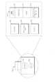
図3は、本開示の一実施形態による、図1のハブ100の簡略化された例示的なハードウェアブロック図を示している。図3に示されているように、ハブ100のハウジング108は、計測器ボード302と、ディスプレイ104と、メモリ304と、シリアルポート210、チャネルポート212、イーサネット(登録商標)ポート305、ナースコールポート306、標準的なUSBもしくは同様のものを含む他の通信ポート308、およびドッキングステーションインターフェース310を含む様々な通信接続部とを位置決めし、および/または包含する。計測器ボード302は、ボード間通信を含む、本明細書で説明されている通信および機能を使用可能にするための通信相互接続部、配線、ポート、および同様のものを含む1つまたは複数の基板を備える。コアボード312は、主パラメータ、信号、ならびに他のプロセッサおよびメモリを備え、携帯型モニタボード(「RIB」)314は、モニタ102および1つまたは複数のプロセッサに対する患者電気的隔離を備え、チャネルボード(「MID」)316は、任意選択の患者電気的隔離および電源318を含むチャネルポート212との通信を制御し、無線ボード320は、ワイヤレス通信に対して構成されているコンポーネントを備える。それに加えて、計測器ボード302は、有利には、1つまたは複数のプロセッサおよびコントローラ、バス、あらゆる種類の通信接続機能および電子機器、メモリ、EPROMリーダーを含むメモリリーダー、ならびに本明細書の開示から当業者に認識可能な他の電子機器を備えるものとしてよい。各ボードは、上で指定されたタスクおよび他のタスクを遂行するために位置決めおよび支持用の基板、通信用の相互接続、コントローラ、論理デバイスを含む電子コンポーネント、ハードウェア/ソフトウェアの組合せ、および同様のものを備える。3 illustrates a simplified exemplary hardware block diagram of the hub 100 of FIG. 1 according to one embodiment of the present disclosure. As shown in FIG. 3, the housing 108 of the hub 100 positions and/or contains an instrument board 302, a display 104, a memory 304, and various communication connections including a serial port 210, a channel port 212, an Ethernet port 305, a nurse call port 306, other communication ports 308 including standard USB or the like, and a docking station interface 310. The instrument board 302 comprises one or more boards including communication interconnects, wiring, ports, and the like for enabling the communications and functions described herein, including board-to-board communications. The core board 312 includes the main parameters, signals, and other processors and memory, the portable monitor board ("RIB") 314 includes patient electrical isolation for the monitor 102 and one or more processors, the channel board ("MID") 316 controls communication with the channel port 212 including optional patient electrical isolation and power supply 318, and the radio board 320 includes components configured for wireless communication. In addition, the instrument board 302 may advantageously include one or more processors and controllers, buses, any type of communication connectivity and electronics, memory, memory readers including EPROM readers, and other electronics that would be recognizable to one skilled in the art from the disclosure herein. Each board includes a positioning and support substrate, communication interconnects, controllers, electronic components including logic devices, hardware/software combinations, and the like to accomplish the tasks specified above and other tasks.
当業者であれば、本明細書の開示から、計測器ボード302は多数の方法で編成された多数の電子コンポーネントを備え得ることを理解するであろう。上で開示されているものなどの異なるボードを使用することで、有利には、複雑なシステムへの編成および区画化がなされる。Those skilled in the art will appreciate from the disclosure herein that the instrument board 302 may include numerous electronic components organized in numerous ways. Using different boards such as those disclosed above may advantageously provide organization and compartmentalization into complex systems.
図4は、本開示の一実施形態による、図1のハブ100の例示的な取り外し可能ドッキングステーション400の斜視図を示している。図4に示されているように、ドッキングステーション400は、携帯型患者モニタ102への機械的嵌合を提供し、モニタ102がドッキングされたときに安全な機械的支持をもたらす。ドッキングステーション400は、携帯型モニタ102のハウジングの外周に類似する形状の空洞402を備える。ステーション400は、ハブ100との通信を提供する1つまたは複数の電気コネクタ404も備える。ボルトで装着されるように図示されているが、ドッキングステーション400は、スナップ式で嵌められるか、移動可能なタブもしくはキャッチを使用するか、磁気で取り付けられるか、または本明細書の開示から当業者に知られる多種多様の取り付けメカニズムもしくはメカニズムの組合せを採用し得る。一実施形態において、ドッキングステーション400の取り付けは、ドッキングされたときに、モニタ102およびドッキングステーションが、たとえば、ハブ100がうっかりドンとぶつかるなどした場合などでも、計測器を損傷するおそれのある仕方でうっかり脱着されることがあり得ないように十分に安全であるべきであり、モニタ102およびドッキングステーション400は無傷のままであるべきである。4 illustrates a perspective view of an exemplary removable docking station 400 for the hub 100 of FIG. 1, according to one embodiment of the present disclosure. As shown in FIG. 4, the docking station 400 provides a mechanical fit to the portable patient monitor 102, providing secure mechanical support when the monitor 102 is docked. The docking station 400 includes a cavity 402 shaped similar to the periphery of the housing of the portable monitor 102. The station 400 also includes one or more electrical connectors 404 that provide communication with the hub 100. Although illustrated as being bolted, the docking station 400 may be snap-fit, use movable tabs or catches, be magnetically attached, or employ a wide variety of attachment mechanisms or combinations of mechanisms known to those of skill in the art from the disclosure herein. In one embodiment, the attachment of the docking station 400 should be sufficiently secure that when docked, the monitor 102 and docking station cannot be accidentally detached in a manner that could damage the instrument, such as if the hub 100 is accidentally banged, and the monitor 102 and docking station 400 should remain intact.
ハブ100のハウジング108は、ドッキングステーション400を収納する空洞406も備える。携帯型患者モニタ102に対するフォームファクタへの変更が生じる範囲において、ドッキングステーション400は、有利には、取り外し可能であり、交換可能である。ドッキングステーション400と同様に、ハブ100は、ハウジング108の空洞406内に、ドッキングステーション400への電気的通信を提供する電気コネクタ408を備える。一実施形態において、ドッキングステーション400は、米国特許公開第2002/0140675号において開示されているような、それ専用のマイクロコントローラおよび処理機能を備える。他の実施形態では、ドッキングステーション400は、電気コネクタ408を通じて通信を行う。The housing 108 of the hub 100 also includes a cavity 406 that houses the docking station 400. To the extent that changes to the form factor for the portable patient monitor 102 occur, the docking station 400 is advantageously removable and replaceable. Like the docking station 400, the hub 100 includes an electrical connector 408 within the cavity 406 of the housing 108 that provides electrical communication to the docking station 400. In one embodiment, the docking station 400 includes its own microcontroller and processing capabilities, such as those disclosed in U.S. Patent Publication No. 2002/0140675. In other embodiments, the docking station 400 communicates through the electrical connector 408.
図4は、以下で詳しく説明されている万能医療用コネクタとしてチャネルポート212用の開口部を備えるハウジング108も示している。Figure 4 also shows the housing 108 with an opening for a channel port 212 as a universal medical connector, which is described in more detail below.
図5は、本開示の一実施形態による、図1のハブ100からドッキングを解除された例示的な携帯型患者モニタ502および504の斜視図を示している。図5に示されているように、モニタ502は取り外されてよく、モニタ504などの他のモニタも提供され得る。ドッキングステーション106は、元のドッキングステーション106と機械的に嵌合し、モニタ504と機械的に嵌合可能なフォームファクタをもたらす追加のドッキングステーション506を含む。一実施形態において、モニタ504は、ハブ100の積み重ねられたドッキングステーション506および106と機械的におよび電気的に嵌合する。本明細書の開示から当業者によって容易に理解され得るように、ドッキングステーションの積み重ね可能な機能は、ハブ100に多種多様の患者監視デバイスを充電し、通信し、およびインターフェースするためのきわめて柔軟性の高いメカニズムを提供する。上で指摘されているように、ドッキングステーションは、積み重ねられるか、または他の実施形態では、取り外して交換することが可能である。5 illustrates a perspective view of exemplary portable patient monitors 502 and 504 undocked from the hub 100 of FIG. 1 according to one embodiment of the present disclosure. As shown in FIG. 5, the monitor 502 may be removed and other monitors such as the monitor 504 may be provided. The docking station 106 includes an additional docking station 506 that mechanically mates with the original docking station 106 and provides a form factor that is mechanically matable with the monitor 504. In one embodiment, the monitor 504 mechanically and electrically mates with the stacked docking stations 506 and 106 of the hub 100. As can be readily appreciated by those skilled in the art from the disclosure herein, the stackable feature of the docking stations provides the hub 100 with an extremely flexible mechanism for charging, communicating, and interfacing a wide variety of patient monitoring devices. As noted above, the docking stations can be stacked or, in other embodiments, removed and replaced.
図6は、従来の患者電気的隔離原理の簡略化されたブロック図を示している。図6に示されているように、ホストデバイス602は、一般的に、通信および電源を通じて患者デバイス604に関連付けられている。患者デバイス604は多くの場合、センサまたは同様のものなどの、患者の近くにあるまたは患者に接続された電子機器を含むので、特定の安全要求条件により、たとえば、ホストデバイスに接続されている配電網からのエネルギーの電気的サージに対する患者への電気的経路があるべきでないことを規定する。これは、一般的に、当技術分野で知られている用語である「患者隔離」を指し、本明細書ではホストデバイス602と患者デバイス604との間の直接的な、途切れのない電気的経路の取り外しを含む。そのような隔離は、たとえば、電源導体608および通信導体610上の隔離デバイス606を通じて実現される。隔離デバイス606は、トランス、光エネルギーを放出し、検出する光デバイス、および同様のものを含むことができる。特に電源導体上の、隔離デバイスの使用は、コンポーネントに関して高く付き、サイズの点でも費用がかかり、電力を浪費する可能性がある。従来、隔離デバイスは患者デバイス604に組み込まれたが、患者デバイス604は小型化される傾向にあり、すべてのデバイスが隔離を組み込むわけではない。Figure 6 shows a simplified block diagram of a conventional patient electrical isolation principle. As shown in Figure 6, a host device 602 is generally associated with a patient device 604 through communication and power sources. Because the patient device 604 often includes electronics near or connected to the patient, such as sensors or the like, certain safety requirements dictate that there should be no electrical path to the patient for electrical surges of energy, for example from the power grid connected to the host device. This generally refers to "patient isolation," a term known in the art, and includes herein the removal of a direct, uninterrupted electrical path between the host device 602 and the patient device 604. Such isolation is achieved, for example, through isolation devices 606 on the power conductors 608 and communication conductors 610. The isolation devices 606 can include transformers, optical devices that emit and detect light energy, and the like. The use of isolation devices, especially on the power conductors, can be expensive in terms of components, costly in terms of size, and wasteful of power. Traditionally, isolation devices have been built into the patient device 604, but patient devices 604 are trending toward smaller sizes and not all devices incorporate isolation.
図7Aは、本開示の一実施形態による例示的な任意選択の患者隔離システムの簡略化されたブロック図を示している。図7Aに示されているように、ホストデバイス602は、隔離デバイス606を通じて隔離された患者デバイス604と通信する。しかしながら、特定の患者デバイスに関連付けられているメモリ702は、ホスト602に、そのデバイスが隔離された電源を必要とするかどうかを通知する。患者デバイス708がある種のカフ、輸液ポンプ、換気装置、または同様のものなど、隔離された電源を必要としない場合、ホスト602は信号経路710を通じて非隔離電源を提供することができる。この電源は、隔離された電源導体608を通じて費用効果よく提供され得るものに比べてかなり高いことがある。一実施形態において、非隔離患者デバイス708は、そのような通信が典型的にはより低い電圧であり、コストが法外に高いわけではないので隔離通信を受ける。当業者であれば、通信も非隔離とすることが可能であることを本明細書の開示から認識するであろう。したがって、図7Aはホスト602と多種多様の潜在的な患者デバイス604、708との間の任意選択の患者隔離を行う患者隔離システム700を示している。一実施形態において、ハブ100は、類似の任意選択の患者隔離原理を組み込んだチャネルポート212を備える。7A illustrates a simplified block diagram of an exemplary optional patient isolation system according to one embodiment of the present disclosure. As shown in FIG. 7A, a host device 602 communicates with an isolated patient device 604 through an isolation device 606. However, a memory 702 associated with a particular patient device informs the host 602 whether the device requires an isolated power source. If the patient device 708 does not require an isolated power source, such as some type of cuff, infusion pump, ventilator, or the like, the host 602 can provide a non-isolated power source through a signal path 710. This power source may be significantly more expensive than what can be cost-effectively provided through an isolated power conductor 608. In one embodiment, the non-isolated patient device 708 receives isolated communication because such communication is typically lower voltage and not cost-prohibitive. One skilled in the art will recognize from the disclosure herein that communication can also be non-isolated. Thus, FIG. 7A illustrates a patient isolation system 700 that provides optional patient isolation between the host 602 and a wide variety of potential patient devices 604, 708. In one embodiment, the hub 100 includes a channel port 212 that incorporates similar optional patient isolation principles.
図7Bは、本開示の一実施形態による図7Aのシステムに対する例示的な任意選択の非隔離電力レベルを追加したものである。図7Bに示されているように、ホスト602が、患者デバイス604が自己隔離患者デバイス708を含み、したがって隔離電力を必要としないことを認識した後、ホスト602は別個の導体710を通じて電力を提供する。電力は隔離されていないので、メモリ702は、また、ホスト602に電力要求条件を課すことができ、これは2つまたはそれ以上の電圧もしくは電力レベルのうちから選択するものとしてよい。図7Bにおいて、ホスト602は、約12ボルトなどの、いずれか高い電力を提供するが、広範な電圧または約24ボルト以上などの非常に高い電力を有し得るが、患者デバイス708に対して広範な電圧を有することが可能である。当業者であれば、電源電圧は、有利には、実質的に任意のデバイス708の特定の要件を満たすように変えることができ、および/またはメモリは、広範な非隔離電力を患者デバイス708に供給したホスト602に情報を供給することが可能であることを認識するであろう。7B adds an exemplary optional non-isolated power level to the system of FIG. 7A according to one embodiment of the present disclosure. As shown in FIG. 7B, after the host 602 recognizes that the patient device 604 includes a self-isolated patient device 708 and therefore does not require isolated power, the host 602 provides power over a separate conductor 710. Since the power is not isolated, the memory 702 can also impose power requirements on the host 602, which may be a selection between two or more voltages or power levels. In FIG. 7B, the host 602 can have a wide range of voltages for the patient device 708, providing either high power, such as about 12 volts, but can have a wide range of voltages or very high power, such as about 24 volts or higher. Those skilled in the art will recognize that the power supply voltage can be advantageously varied to meet the specific requirements of virtually any device 708, and/or the memory can provide information to the host 602 that it has provided a wide range of non-isolated power to the patient device 708.
さらに、メモリ702を使用することで、ホスト602は、隔離電源であるか、またはより高電圧の非隔離電源のうちの1つもしくは複数であるかに関係なく、任意の未使用電源を単純に使用可能にしないことを決定し、それによってホストの効率を高め得る。Furthermore, using memory 702, host 602 may determine to simply not enable any unused power sources, whether they are isolated power sources or one or more of the higher voltage non-isolated power sources, thereby increasing the efficiency of the host.
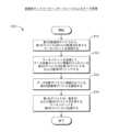
図8は、本開示の一実施形態による、簡略化された例示的な万能医療用コネクタ構成プロセス800を示している。図8に示されているように、このプロセスはステップ802を含み、前記の説明で開示されているような任意選択の患者隔離を組み込んだ万能医療用コネクタにケーブルが取り付けられる。ステップ804において、ホストデバイス602またはハブ100、より具体的には、計測器ボードのチャネルデータボード316またはEPROMリーダーは、メモリ702に記憶されているデータを読み出し、ステップ806において、接続デバイスが隔離電源を必要とするかどうかを決定する。ステップ808において、隔離電源が必要なときに、ハブ100は、有利には、隔離電源を使用可能にし、ステップ810において、隔離通信を使用可能にするものとしてよい。ステップ806において、隔離電源が必要ないときに、ハブ100は、単純に、任意選択のステップ812において、非隔離電源を使用可能にし、通信が隔離されたままである実施形態において、ステップ810で隔離通信を使用可能にするものとしてよい。他の任意選択の実施形態において、ステップ806で、隔離電源が必要ないときに、ハブ100は、ステップ814において、メモリ702からの情報を使用して患者デバイス708に必要な電力量を決定するものとしてよい。十分な電力が利用可能でないときには、たとえば、他の接続されているデバイスも接続されている電源を使用しているので、ステップ816において、その電源および電力が提供されないことを示すメッセージが表示され得る。十分な電力が利用可能であるときには、任意選択のステップ812で非隔離電源を使用可能にするものとしてよい。代替的に、任意選択のステップ818で、より高いまたは低い電力が望ましいことをメモリ702が示しているかどうかを決定し得る。より高い電力が望ましいときには、ハブ100は、ステップ820においてより高い電力を使用可能にし、そうでないときには、ステップ822においてより低い電力を使用可能にし得る。次いで、ハブ100は、ステップ810において隔離通信を使用可能にする。一実施形態において、ハブ100は、ステップ818において、単純に、どれだけの電力が必要かを決定し、自己隔離デバイス708に少なくとも十分な電力を供給し得る。8 illustrates a simplified exemplary universal medical connector configuration process 800 according to one embodiment of the present disclosure. As shown in FIG. 8, the process includes step 802, where a cable is attached to a universal medical connector incorporating optional patient isolation as disclosed in the above description. In step 804, the host device 602 or the hub 100, more specifically the channel data board 316 of the instrument board or an EPROM reader, reads the data stored in the memory 702 and determines in step 806 whether the connected device requires an isolated power source. In step 808, when an isolated power source is required, the hub 100 may advantageously enable the isolated power source and in step 810 enable isolated communications. In step 806, when an isolated power source is not required, the hub 100 may simply enable a non-isolated power source in optional step 812 and in embodiments where communications remain isolated, enable isolated communications in step 810. In another optional embodiment, when an isolated power source is not needed in step 806, the hub 100 may use information from the memory 702 to determine the amount of power needed for the patient device 708 in step 814. When sufficient power is not available, a message may be displayed in step 816 indicating that the power source and power will not be provided, for example because other connected devices are also using the connected power source. When sufficient power is available, a non-isolated power source may be enabled in optional step 812. Alternatively, in optional step 818, it may be determined whether the memory 702 indicates that higher or lower power is desired. When higher power is desired, the hub 100 may enable higher power in step 820, and when not, the hub 100 may enable lower power in step 822. The hub 100 then enables isolated communication in step 810. In one embodiment, the hub 100 may simply determine how much power is needed in step 818 and provide at least enough power to the self-isolated device 708.
当業者であれば、本明細書の開示から、ハブ100は十分な電力が利用可能であるか確認し得ないか、またはメモリ702からの情報に基づき1つ、2つ、または多くのレベルの非隔離電圧を供給し得るであろう。Those skilled in the art will appreciate from the disclosure herein that the hub 100 may not determine whether sufficient power is available or may provide one, two, or many levels of non-isolated voltage based on information from the memory 702.
図9Aおよび図9Bは、従来の隔離要求条件に比べて小さい断面サイズおよび断面形状を有する例示的な万能医療用コネクタ900を示す簡略化されたブロック図を示している。一実施形態において、コネクタ900は、一方の側910の非隔離信号を他方の側920の隔離信号から物理的に分離するが、これらの側は反転できる。そのような分離の間のギャップは、患者隔離を定める安全規則によって少なくとも一部は規定され得る。一実施形態において、側910と側920との間の距離は小さすぎるように見える場合がある。9A and 9B show simplified block diagrams illustrating an exemplary universal medical connector 900 having a cross-sectional size and cross-sectional shape that is small relative to conventional isolation requirements. In one embodiment, the connector 900 physically separates non-isolated signals on one side 910 from isolated signals on the other side 920, although the sides can be reversed. The gap between such separations may be dictated at least in part by safety regulations governing patient isolation. In one embodiment, the distance between sides 910 and 920 may appear to be too small.
図9Bの異なる斜視図からわかるように、コネクタの間の距離「x」は小さいように見える。しかしながら、このギャップがあると、この距離は導体間の非直接的経路を含む。たとえば、ショートは経路904を移動しなければならず、そのような経路の距離は、距離が「x」より大きいという点でそのような安全規則の範囲内、またはそれ以上である。非直線経路904は、たとえば、ハンダが様々なピンをPCBボードに接続するボードコネクタ側などで、コネクタ全体を通して生じることは特筆すべきである。As can be seen from the different perspective of FIG. 9B, the distance "x" between the connectors appears small. However, with this gap, this distance includes a non-direct path between the conductors. For example, a short must travel path 904, and the distance of such path is within or beyond such safety regulations in that the distance is greater than "x." It is notable that the non-straight path 904 occurs throughout the connector, for example, at the board connector side where the solder connects the various pins to the PCB board.
図10は、例示的な万能医療用コネクタとして例示的な計測器側部チャネル入力1000を示す、図1のハブ100の側部の斜視図を示している。図10に示されているように、入力は非隔離側910、隔離側920、およびギャップを含む。一実施形態において、メモリ702は、非隔離側のピンを通じて通信する。FIG. 10 illustrates a side perspective view of the hub 100 of FIG. 1 showing an exemplary meter side channel input 1000 as an exemplary universal medical connector. As shown in FIG. 10, the input includes a non-isolated side 910, an isolated side 920, and a gap. In one embodiment, the memory 702 communicates through pins on the non-isolated side.
図11A~図11Kは、本開示の実施形態による、例示的なオス万能医療用コネクタおよび嵌合するメス万能医療用コネクタの様々な図を示している。たとえば、図11G1および図11G2は、様々な好ましいが、必要ではないサイズ設定を示しており、図11Hは、メモリ702などの電子コンポーネントをコネクタに組み込むことを示している。図11I~図11Kは、万能医療用コネクタに接続するときの配線図およびケーブルそれ自体のケーブル布線詳細を例示している。FIGS. 11A-11K show various views of an exemplary male universal medical connector and a mating female universal medical connector according to an embodiment of the present disclosure. For example, FIGS. 11G1 and 11G2 show various preferred, but not required, sizing configurations, and FIG. 11H shows the incorporation of electronic components such as memory 702 into the connector. FIGS. 11I-11K illustrate the wiring diagram when connecting to the universal medical connector and the cabling details of the cable itself.
図12は、本開示の一実施形態による、図1のハブに対するチャネルシステムを示す簡略化されたブロック図を示している。図12に示されているように、上の図11に示されているようなオスケーブルコネクタは、EPROMなどのメモリを備える。メモリは、有利には、ハブ100が受信することを期待し得るデータのタイプ、およびそれを受信する方法を説明する情報を記憶する。ハブ100のコントローラはEPROMと通信して、データの受信の仕方、および可能ならば、ディスプレイ104上にデータを表示する仕方、必要なときのアラーム、および同様のものをネゴシエートする。たとえば、医療用デバイスサプライヤは、ハブプロバイダにコンタクトし、デバイスから出力されるデータのタイプをどのように記述するかについてサプライヤに指針を与えるソフトウェア開発キット(「SDK」)を受け取るものとしてよい。SDKで作業した後、マップ、画像、または他の翻訳ファイルは、有利には、EPROM内にロードされるものとしてよく、さらには上で説明されている電力要件および隔離要件もロードされ得る。チャネルケーブルがチャネルポート212を通してハブ100に接続されると、ハブ100はEPROMを読み出し、ハブ100のコントローラは着信データの処理方法をネゴシエートする。FIG. 12 shows a simplified block diagram illustrating a channel system for the hub of FIG. 1 according to one embodiment of the present disclosure. As shown in FIG. 12, a male cable connector, such as that shown in FIG. 11 above, includes a memory, such as an EPROM. The memory advantageously stores information describing the type of data the hub 100 may expect to receive and how to receive it. The controller of the hub 100 communicates with the EPROM to negotiate how to receive the data and, if possible, how to display the data on the display 104, alarms when necessary, and the like. For example, a medical device supplier may contact the hub provider and receive a software development kit ("SDK") that provides guidance to the supplier on how to describe the type of data output from the device. After working with the SDK, maps, images, or other translation files may advantageously be loaded into the EPROM, as well as the power and isolation requirements described above. When a channel cable is connected to hub 100 through channel port 212, hub 100 reads the EPROM and the controller in hub 100 negotiates how to handle the incoming data.
図13は、図12のEPROMに記憶され得る例示的な論理的チャネル構成を示している。図13に示されているように、各着信チャネルは1つまたは複数のパラメータを記述する。各パラメータはハブ100が着信データに関して知るべきであるものであれば何でも記述する。たとえば、ハブ100は、データがストリーミングデータであるか、波形データであるか、すでに決定されたパラメータ測定データであるか、データ上の範囲であるか、データ配信速度であるか、データのユニットであるか、ユニットのステップであるか、表示する色であるか、アラーム計算のための複雑なアルゴリズムを含む、アラームパラメータおよび閾値であるか、パラメータ値で駆動される他のイベントであるか、これらの組合せであるか、または同様のものであるかを知ることを望んでいる場合がある。それに加えて、パラメータ情報は、ハブ100によって受信されるパラメータまたは他のデータ間のデータ同期またはデータ同期の近似を補助するためのデバイス遅延時間を含み得る。一実施形態において、SDKは、着信データのタイプおよび順序を自己記述するスキーマをデバイスサプライヤに提示する。一実施形態において、この情報は、有利には、ハブ100とネゴシエートし、圧縮および/または暗号化を着信データストリームに適用するかどうかを決定する。13 illustrates an exemplary logical channel configuration that may be stored in the EPROM of FIG. 12. As illustrated in FIG. 13, each incoming channel describes one or more parameters. Each parameter describes anything the hub 100 needs to know about the incoming data. For example, the hub 100 may want to know whether the data is streaming data, waveform data, already determined parameter measurement data, ranges on the data, data delivery rates, units of data, steps of units, colors to display, alarm parameters and thresholds including complex algorithms for alarm calculations, other events driven by parameter values, combinations of these, or the like. In addition, the parameter information may include device latency to aid in data synchronization or approximation of data synchronization between parameters or other data received by the hub 100. In one embodiment, the SDK presents a schema to the device supplier that self-describes the type and order of incoming data. In one embodiment, this information is advantageously negotiated with the hub 100 to determine whether compression and/or encryption should be applied to the incoming data stream.
そのようなオープンアーキテクチャは、有利には、デバイスメーカーが、前述の説明で開示されているような表示、処理、およびデータ管理のためにハブ100にデバイスの出力をポーティングすることができるようにする。ケーブルコネクタを通じての実装によって、デバイスメーカーは、その元のデバイスの再プログラミングを回避し、むしろ、単純に、ケーブルコネクタを通じて、すでに存在している出力がどのようにフォーマットされるかをハブ100に知らせるだけである。さらに、データをハブ100によってすでに理解されている言語で記述することによって、ハブ100は、また、「ハブにとっては新しいものである」医療用デバイスからのデータに対応できるようにソフトウェアをアップグレードすることを回避する。Such an open architecture advantageously allows device manufacturers to port the output of their devices to the hub 100 for display, processing, and data management as disclosed in the preceding description. By implementing through the cable connector, the device manufacturer avoids reprogramming its original device, but rather simply informs the hub 100 how the output already present through the cable connector is formatted. Furthermore, by describing the data in a language already understood by the hub 100, the hub 100 also avoids having to upgrade its software to accommodate data from medical devices that are "new to the hub."
図14は、本開示の一実施形態によりチャネルを構成するための簡略化された例示的なプロセスを示している。図14に示されているように、ハブプロバイダは、ステップ1402においてSDKをデバイスメーカーに提供し、次いで、メーカーはSDKを使用してステップ1404においてデバイスからの出力データチャネルを自己記述する。一実施形態において、SDKは、開発の指針となる一連の質問であり、他の実施形態では、SDKは、データの挙動を記述するための言語およびスキーマを提供する。FIG. 14 illustrates a simplified exemplary process for configuring a channel according to one embodiment of the present disclosure. As shown in FIG. 14, the hub provider provides an SDK to the device manufacturer in step 1402, and the manufacturer then uses the SDK to self-describe the output data channel from the device in step 1404. In one embodiment, the SDK is a set of questions that guide development, while in other embodiments, the SDK provides a language and schema for describing data behavior.
デバイスプロバイダがデータを記述した後、ハブプロバイダは、ステップ1405においてケーブルコネクタ内のメモリに記憶するバイナリイメージまたは他のファイルを作成するが、SDKは、イメージを作成し、それを単にハブプロバイダに伝達し得る。ケーブルコネクタは、ステップ1410において、OEM部品としてプロバイダに提供され、プロバイダは、ステップ1412においてデバイス上の出力ポートと機械的および電気的に嵌合するようにケーブルを製作し、製造する。After the device provider describes the data, the hub provider creates a binary image or other file to store in memory in the cable connector in step 1405, although the SDK may create the image and simply communicate it to the hub provider. The cable connector is provided to the provider as an OEM part in step 1410, and the provider creates and manufactures the cable to mechanically and electrically mate with the output port on the device in step 1412.
介護人が、一方の端部がデバイスプロバイダのシステムとマッチし、他方のOEM端がそのチャネルポート212においてハブ100とマッチする、適切に製造されたケーブルを手に入れた後、ステップ1452において、介護人は、デバイス同士の間でハブを接続することができる。ステップ1454において、ハブ100はメモリを読み出し、隔離または非隔離の電力を供給し、ケーブルコントローラおよびハブ100はデータ配信のためのプロトコルまたはスキーマをネゴシエートする。一実施形態において、ケーブル上のコントローラはプロトコルをネゴシエートするものとしてよく、代替的一実施形態では、ハブ100のコントローラはハブ上の他のプロセッサと特定のプロトコルをネゴシエートする。プロトコルが設定された後、ハブ100は、インテリジェントな方式で、着信データストリームを使用し、表示し、他の何らかの形で処理することができる。After the caregiver has a properly manufactured cable with one end matching the device provider's system and the other OEM end matching the hub 100 at its channel port 212, the caregiver can connect the hub between the devices in step 1452. In step 1454, the hub 100 reads memory, provides isolated or non-isolated power, and the cable controller and hub 100 negotiate a protocol or schema for data delivery. In one embodiment, a controller on the cable may negotiate the protocol, and in an alternative embodiment, the controller of the hub 100 negotiates a particular protocol with another processor on the hub. After the protocol is set, the hub 100 can use, display, or otherwise process the incoming data stream in an intelligent manner.
本明細書で説明されている万能医療用コネクタを使用することで、各デバイスに対してソフトウェアアップグレードを必要とすることとは反対にケーブルコネクタの直接的プログラミングを通じてハブ100に接続できるデバイスは無数である。By using the universal medical connector described herein, an unlimited number of devices can be connected to the hub 100 through direct programming of the cable connector as opposed to requiring software upgrades for each device.
図15は、本開示の一実施形態による、入力チャネルを形成するための例示的な取り付けられたボードインケーブル(「BIC」)を含む、図1のハブの斜視図を示している。図15に示されているように、SEDLineの意識深度ボードは、表示および介護人による再検討のために適切な患者センサからのデータをハブ100に伝達する。説明されているように、ボードのプロバイダは、データチャネルを記述するためにSDKを使用するだけでよく、ハブ100は、データを介護人に提示する仕方を理解する。FIG. 15 illustrates a perspective view of the hub of FIG. 1 including an exemplary attached board-in cable ("BIC") for forming an input channel, according to one embodiment of the present disclosure. As shown in FIG. 15, the SEDLine Depth of Consciousness board communicates data from the appropriate patient sensors to the hub 100 for display and review by the caregiver. As described, the board provider need only use the SDK to describe the data channel, and the hub 100 will understand how to present the data to the caregiver.
図16は、例示的なシリアルデータ入力を示す、図1のハブ100の背面の斜視図を示している。一実施形態において、入力はRJ45ポートなどを含む。当技術分野において理解されているように、これらのポートは、コンピュータ、ネットワークルータ、スイッチ、およびハブ上にあるポートに類似するデータポートを含む。一実施形態において、複数のこれらのポートは、様々なデバイスからのデータをハブ100において識別されている特定の患者に関連付けるために使用される。図16は、スピーカー、ナースコールコネクタ、イーサネット(登録商標)コネクタ、USB、電源コネクタ、および医療用接地端子も示している。FIG. 16 illustrates a perspective view of the back of the hub 100 of FIG. 1 showing exemplary serial data inputs. In one embodiment, the inputs include RJ45 ports or the like. As understood in the art, these ports include data ports similar to those found on computers, network routers, switches, and hubs. In one embodiment, a number of these ports are used to associate data from various devices with a particular patient identified in the hub 100. FIG. 16 also illustrates a speaker, nurse call connector, Ethernet connector, USB, power connector, and medical ground terminal.
図17Aは、本開示の一実施形態による、図1のハブ100のシリアルデータ接続を通じて通信する例示的な監視環境を示している。図示されているように、また前述の説明で開示されているように、ハブ100はシリアルデータポート210を使用して、電子ベッド、輸液ポンプ、換気装置、生命兆候モニタ、および同様のものを含む、監視環境内の様々なデバイスからデータを収集するものとしてよい。これらのデバイスから受信されるデータとチャネルポート212を通じて受信されるデータとの違いは、ハブ100がこのデータのフォーマットまたは構造を知り得ない点にある。ハブ100は、このデータからの情報を表示すること、または計算もしくは処理でこのデータを使用することは、し得ない。しかしながら、ハブ100を通じてデータをポーティングすることで、データを、前述のサーバ204およびエンドシステム206を含む、介護人システムのチェーン全体において特に監視されている患者に都合よく関連付ける。一実施形態において、ハブ100は、着信データに関する、そのデータをハブ100からのデータと同期させることを試みるのに十分な情報を決定し得る。17A illustrates an exemplary monitoring environment communicating through a serial data connection of the hub 100 of FIG. 1 according to one embodiment of the present disclosure. As illustrated and disclosed in the above description, the hub 100 may use the serial data port 210 to collect data from various devices in the monitoring environment, including electronic beds, infusion pumps, ventilators, vital signs monitors, and the like. The difference between the data received from these devices and the data received through the channel port 212 is that the hub 100 does not know the format or structure of this data. The hub 100 may not display information from this data or use this data in calculations or processing. However, porting the data through the hub 100 conveniently associates the data with the patient being specifically monitored throughout the chain of caregiver systems, including the server 204 and end systems 206 discussed above. In one embodiment, the hub 100 may determine enough information about the incoming data to attempt to synchronize that data with the data from the hub 100.
図17Bにおいて、制御画面は、受信されているデータのタイプに関する情報を提供し得る。一実施形態において、データの隣にある緑色のライトは、デバイスへの接続および接続が行われるシリアル入力を指示する。In FIG. 17B, the control screen may provide information regarding the type of data being received. In one embodiment, a green light next to the data indicates the connection to the device and the serial input to which the connection is made.
図18は、本開示の一実施形態による、簡略化された例示的な患者データフロープロセスを示している。図示されているように、ステップ1802において患者が入院し介護人環境内に入ると、患者に関するデータが介護人バックエンドシステム206に書き込まれる。サーバ204は、有利には、ステップ1804においてこの情報を取得するか、または受信し、次いで、それをハブ100からアクセスできるようにするものとしてよい。介護人がステップ1806においてハブ100を患者に割り当てるときに、介護人は、単純に、現在利用可能な患者データを見て、現在監視されている特定の患者を選択する。次いで、ハブ100は、ステップ1808において、これが受信し決定する測定、監視、および治療データをその患者に関連付ける。介護人は、再び、別のデバイスを患者に割り当てる必要は、そのデバイスが(1)ドッキングステーション、(2)万能医療用コネクタ、(3)シリアルデータコネクタ、または(4)当業者に知られている他の通信メカニズムを用いてハブ100を通じて通信している限り、ない。ステップ1810において、受信された、処理された、および/または決定されたデータの一部または全部が上で説明されているサーバシステムに受け渡される。FIG. 18 illustrates a simplified exemplary patient data flow process according to one embodiment of the disclosure. As illustrated, when a patient is admitted and enters the caregiver environment in step 1802, data about the patient is written to the caregiver backend system 206. The server 204 may advantageously obtain or receive this information in step 1804 and then make it accessible to the hub 100. When the caregiver assigns the hub 100 to a patient in step 1806, the caregiver simply looks at the currently available patient data and selects the particular patient currently being monitored. The hub 100 then associates the measurement, monitoring, and treatment data it receives and determines with that patient in step 1808. The caregiver does not need to assign another device to the patient again, as long as that device communicates through the hub 100 using (1) a docking station, (2) a universal medical connector, (3) a serial data connector, or (4) other communication mechanisms known to those skilled in the art. In step 1810, some or all of the received, processed, and/or determined data is passed to the server system described above.
図19A~図19Jは、本開示の実施形態による、図1のハブ100にドッキングされている携帯型患者モニタに対する解剖学的グラフィックスの例示的な表示を示している。図19Aに示されているように、心臓、肺、および呼吸器系は、脳がハイライト表示されていない間示されている。したがって、介護人は、携帯型患者モニタ接続またはチャネルデータポートを通じて意識深度監視または脳酸素測定システムがハブ100と現在通信していないと容易に決定することができる。しかしながら、音響または他の呼吸データおよび心臓データがハブ100に伝達されているか、またはハブ100によって測定されている可能性が高い。さらに、介護人は、ハブ100が強調されている身体部分に関してアラーム発生データを受信していないと容易に決定することができる。一実施形態において、強調されている部分は、現在測定されている挙動を示すようにアニメーション動画になっているか、または代替的に、所定の様式でアニメーション動画になっているものとしてよい。19A-19J show exemplary displays of anatomical graphics for a portable patient monitor docked to the hub 100 of FIG. 1 according to an embodiment of the present disclosure. As shown in FIG. 19A, the heart, lungs, and respiratory system are shown while the brain is not highlighted. Thus, the caregiver can easily determine that a depth of consciousness monitoring or cerebral oximetry system is not currently communicating with the hub 100 through the portable patient monitor connection or channel data port. However, acoustic or other respiratory and cardiac data is likely being communicated to or measured by the hub 100. Additionally, the caregiver can easily determine that the hub 100 is not receiving alarm generation data for the highlighted body part. In one embodiment, the highlighted part may be animated to show the behavior currently being measured, or alternatively, animated in a predetermined manner.
図19Bは、健康の指標を示す仮想チャネルの追加を示している。図19Bに示されているように、この指標は、「100」まで次第に大きくなる重大度スケールで「34」なので陽性である。健康指標は、問題を示すように陰影も付けられ得る。図19Bとは対照的に、図19Cは、問題になりつつあるか、または問題になってしまっている健康度数、およびアラーム発生心臓グラフィックを示している。したがって、介護人がハブ100上の患者アラームに応答するか、または患者を監視するかもしくは治療している別のデバイスもしくはシステム上で他の何らかの応答をすることにより、患者を診断し、および/または治療するために生命兆候および心臓機能に関係する他のパラメータの再検討が必要であると素早く決定することができる。FIG. 19B illustrates the addition of a virtual channel showing a health indicator. As shown in FIG. 19B, the indicator is positive as it is a "34" on an increasingly severe scale up to "100." The health indicator may also be shaded to indicate a problem. In contrast to FIG. 19B, FIG. 19C illustrates a health number that is becoming or has become a problem, and an alarming cardiac graphic. Thus, by a caregiver responding to the patient alarm on the hub 100, or some other response on another device or system monitoring or treating the patient, it can be quickly determined that a review of vital signs and other parameters related to cardiac function is required to diagnose and/or treat the patient.
図19Dおよび図19Eは、強調されている身体部位に含まれる脳を示しており、これはハブ100が、たとえば、鎮静深度データまたは脳酸素測定データなどの、脳機能に関連するデータを受信していることを意味する。図19Eは、それに加えて、図19Cに類似するアラーム発生心臓機能を示している。FIGS. 19D and 19E show the brain among the highlighted body parts, meaning that the hub 100 is receiving data related to brain function, such as, for example, sedation depth data or cerebral oximetry data. FIG. 19E additionally shows an alarming cardiac function similar to FIG. 19C.
図19Fでは、腎臓などの、追加の臓器が監視されているが、呼吸器系は監視されていない。図19Gでは、アラーム発生心臓機能が図示されており、図19Hでは、アラーム発生循環系が図示されている。図19Iは、肺、心臓、脳、および腎臓とともに健康指標を示している。図19Jは、アラーム発生の肺、心臓、および循環系、さらには健康指標を示している。さらに、図19Jは、たとえば、緊急事態に対して心臓は赤色でアラームを発生し、注意警告に対して循環系は黄色でアラームを発生するなどの、重大度コントラストを示している。当業者であれば、本明細書の開示から適切である他の配色もあることを認識するであろう。In FIG. 19F, additional organs are monitored, such as the kidneys, but not the respiratory system. In FIG. 19G, an alarmed cardiac function is illustrated, and in FIG. 19H, an alarmed circulatory system is illustrated. FIG. 19I illustrates the lungs, heart, brain, and kidneys along with health indicators. FIG. 19J illustrates the alarmed lungs, heart, and circulatory system along with health indicators. Additionally, FIG. 19J illustrates severity contrast, e.g., the heart alarming in red for an emergency and the circulatory system alarming in yellow for a caution warning. Those skilled in the art will recognize other color schemes that may be appropriate from the disclosure herein.
図20A~図20Cは、本開示の実施形態により、それぞれ、データの分離およびデータの重なりを示す測定データの例示的な表示を示している。図21Aおよび図21Bは、本開示の実施形態により、それぞれ、データの分離およびデータの重なりも示す測定データの例示的な表示を示している。FIGS. 20A-20C show example displays of measurement data showing data separation and data overlap, respectively, according to an embodiment of the present disclosure. FIGS. 21A and 21B show example displays of measurement data also showing data separation and data overlap, respectively, according to an embodiment of the present disclosure.
たとえば、音響センサからの音響データは、有利には、呼吸音データを提供し得るが、プレチスモグラフおよびECGまたは他の信号も、別々の波形で掲示され得る(図20A、画面キャプチャの一番上)。モニタは、呼吸数、呼気流、1回換気量、分時拍出量、無呼吸持続時間、呼吸音、ライル(rile)、ロンカイ、喘鳴、および空気流の体積減少または変化などの呼吸音の変化を含む、患者の多種多様な呼吸パラメータのうちのいずれかを決定し得る。それに加えて、いくつかの場合において、システムは、プローブオフ検出を補助する心拍数、心音(S1、S2、S3、S4、および心雑音)、および体液過剰を示す正常から心雑音もしくは分割心音までなどの心音の変化などの、他の生理的音を監視する。For example, acoustic data from an acoustic sensor may advantageously provide respiratory sound data, although plethysmograph and ECG or other signals may also be displayed in separate waveforms (FIG. 20A, top of screen capture). The monitor may determine any of a wide variety of patient respiratory parameters, including respiratory rate, expiratory flow, tidal volume, minute volume, apnea duration, changes in respiratory sounds such as breath sounds, riles, rhonchi, wheezing, and volumetric reductions or changes in airflow. In addition, in some cases, the system monitors other physiological sounds, such as heart rate, heart sounds (S1, S2, S3, S4, and murmurs) that aid in probe-off detection, and changes in heart sounds such as normal to murmurs or split sounds that indicate fluid overload.
複数の生理学的信号の間の視覚的相関を与えることで、信号がいくつかの観察可能な生理学的相関を有する多数の価値ある利点をもたらすことができる。そのような相関の一例として、プレチスモグラフ信号の形態(たとえば、包絡線および/または基線)の変化は、患者の血液または他の体液のレベルを示すことができる。また、これらの変化は、血液量減少または他の体液レベル関係の状態を検出するために監視され得る。たとえば、脈波変動指数は体液レベルの指示を提供し得る。また、プレチスモグラフの信号の形態の変化は、呼吸に相関する。たとえば、プレチスモグラフの信号の包絡線および/または基線の変化は、呼吸に相関する。これは、少なくとも一部は、呼吸時の心臓と肺との間の機械的関係および相互作用などの、人間の解剖学的構造の態様によるものである。Providing visual correlation between multiple physiological signals can provide a number of valuable benefits where the signals have some observable physiological correlates. As one example of such correlation, changes in the morphology (e.g., envelope and/or baseline) of the plethysmographic signal can be indicative of the patient's blood or other bodily fluid level. These changes can also be monitored to detect hypovolemia or other fluid level related conditions. For example, a pleth variability index can provide an indication of bodily fluid levels. Changes in the morphology of the plethysmographic signal also correlate with respiration. For example, changes in the envelope and/or baseline of the plethysmographic signal correlate with respiration. This is due, at least in part, to aspects of human anatomy, such as the mechanical relationship and interaction between the heart and lungs during respiration.
したがって、プレチスモグラフ信号と呼吸信号(図20B)とを重ね合わせることで、操作者は、脈波変動指数などの、プレチスモグラフ信号またはそれから導出された信号の有効性の指標を得ることができる。たとえば、吸息と呼息とを指示する呼吸信号中のバーストがプレチスモグラフ包絡線の頂点と谷の変化と相関する場合、これは、プレチスモグラフ変化が実際に呼吸によるものであり、他の何らかの背景因子によるものでないことを示す視覚的指示を監視要員に与える。同様に、呼吸信号中のバーストがプレチスモグラフ包絡線内の頂点および谷と整列する場合に、これは、呼吸信号中のバーストが患者呼吸音によるものであり、他の何らかの非ターゲット音(たとえば、患者非呼吸音または非患者音)によるものでないことを示す指示を監視要員に提供する。Thus, by overlaying the plethysmograph signal with the respiratory signal (FIG. 20B), the operator can obtain an indication of the validity of the plethysmograph signal or a signal derived therefrom, such as a pleth variability index. For example, if bursts in the respiratory signal indicating inspiration and expiration correlate with changes in the peaks and valleys of the plethysmograph envelope, this provides the monitoring personnel with a visual indication that the plethysmograph changes are indeed due to breathing and not due to some other background factor. Similarly, if bursts in the respiratory signal align with peaks and valleys in the plethysmograph envelope, this provides the monitoring personnel with an indication that the bursts in the respiratory signal are due to patient breath sounds and not due to some other non-target sounds (e.g., non-patient breath sounds or non-patient sounds).
モニタは信号を処理し、2つの信号の間に相関の閾値レベルがあるかどうかを決定するか、または他の何らかの形で相関を評価するようにも構成され得る。しかしながら、互いに重ね合わされている信号を示すことなどによって、それに加えて相関の視覚的指示を提供することによって、この表示は、操作者に特定の生理学的相関の連続的、直観的で、容易に観察可能な測定基準をもたらす。たとえば、重ね合わされている信号を見ることによって、ユーザは、他の方法では確認できない場合のある、時間の経過による相関の動向を観察することができる。The monitor may also be configured to process the signals and determine if there is a threshold level of correlation between the two signals or to assess the correlation in some other way. However, by additionally providing a visual indication of the correlation, such as by showing the signals overlaid on one another, the display provides the operator with a continuous, intuitive, and easily observable metric of a particular physiological correlation. For example, by viewing the overlaid signals, a user can observe trends in correlation over time that may not otherwise be visible.
モニタは、プレチスモグラフおよび呼吸信号の代わりに、またはそれに加えて多種多様の他のタイプの信号の視覚的相関を見せることができる。たとえば、図20Cは、別の例示的な監視表示のスクリーンショットを示している。図20Cの右上部分に示されているように、この表示は、プレチスモグラフ信号、ECG信号、および呼吸信号を重ね合わせたものである。他の構成において、3つより多い異なるタイプの信号が互いに重ね合わされ得る。The monitor can show a visual correlation of a wide variety of other types of signals instead of, or in addition to, the plethysmograph and respiratory signals. For example, FIG. 20C shows a screenshot of another exemplary monitoring display. As shown in the upper right portion of FIG. 20C, this display superimposes the plethysmograph signal, the ECG signal, and the respiratory signal. In other configurations, more than three different types of signals can be superimposed on top of each other.
一実施形態において、ハブ100は、ユーザが信号を互いに重なるように一緒に移動することができるインターフェースを提供する。たとえば、ユーザは、タッチスクリーンインターフェースを使用してプレチスモグラフ信号上に呼吸信号をドラッグして落とすことができるものとしてよい。逆に、ユーザは、これもまたタッチスクリーンインターフェースを使用して、信号分離することができるものとしてよい。別の実施形態では、モニタは、ユーザが押せるボタン、またはユーザが必要な場合に信号を重ね合わせ、分離することを可能にする他の何らかのユーザインターフェースを備える。図21Aおよび図21Bは、それらの信号の類似の分離および連結を示している。In one embodiment, the hub 100 provides an interface that allows the user to move the signals together so that they overlap each other. For example, the user may be able to drag and drop the respiration signal onto the plethysmograph signal using a touch screen interface. Conversely, the user may be able to separate the signals, also using a touch screen interface. In another embodiment, the monitor includes a button that the user can press, or some other user interface that allows the user to overlap and separate the signals as desired. Figures 21A and 21B show a similar separation and combination of the signals.
いくつかの構成において、プレチスモグラフ信号と呼吸信号との間に視覚的相関をもたらすことに加えて、モニタは、さらに、呼吸信号およびプレチスモグラフ信号を処理し、これら2つの信号の間の相関を決定するように構成される。たとえば、モニタはこれらの信号を処理して、プレチスモグラフ信号の包絡線および/または基線の変化の頂点および谷が呼吸信号中のバーストに対応するかどうかを決定し得る。そして、相関の閾値レベルがある、またはないと決定したことに応答して、モニタは、何らかの指示をユーザに提供し得る。たとえば、モニタは、グラフィック指示(たとえば、脈波変動指数指標の色の変化)、可聴アラーム、または他の何らかの指示を提供し得る。モニタは、決定を行う際に1つまたは複数の包絡線検出器または他の適切な信号処理コンポーネントを採用するものとしてよい。In some configurations, in addition to providing a visual correlation between the plethysmograph signal and the respiratory signal, the monitor is further configured to process the respiratory and plethysmograph signals to determine a correlation between the two signals. For example, the monitor may process the signals to determine whether peaks and valleys of the envelope and/or baseline changes of the plethysmograph signal correspond to bursts in the respiratory signal. Then, in response to determining that there is or is not a threshold level of correlation, the monitor may provide some indication to the user. For example, the monitor may provide a graphical indication (e.g., a change in color of the pleth variability index indicator), an audible alarm, or some other indication. The monitor may employ one or more envelope detectors or other suitable signal processing components in making the determination.
いくつかの実施形態において、システムは、グラフィック指示の代わりに、またはそれに加えて患者の呼吸音の可聴指示をさらに提供し得る。たとえば、モニタは、スピーカーを備え得るか、またはイヤーピース(たとえば、ワイヤレスイヤーピース)が監視要員に提供され、患者音の可聴出力を行うものとしてよい。そのような機能を有するセンサおよびモニタの例は、米国特許公開第2011/0172561号において説明されており、参照により本明細書に組み込まれている。In some embodiments, the system may further provide an audible indication of the patient's breathing sounds instead of or in addition to the graphic indication. For example, the monitor may include a speaker or an earpiece (e.g., a wireless earpiece) may be provided to monitoring personnel to provide an audible output of the patient sounds. Examples of sensors and monitors having such functionality are described in U.S. Patent Publication No. 2011/0172561, which is incorporated herein by reference.
上で説明されている利点に加えて、音響信号とプレチスモグラフ信号の両方を説明されている方式で同じディスプレイ上に提示することで、監視要員が、呼吸が存在していないこと、音響信号を劣化させ得る高い環境雑音があること、不適切なセンサ配置であること、などの呼吸休止事象をより容易に検出することを可能にすることができる。In addition to the advantages described above, presenting both the acoustic and plethysmographic signals on the same display in the manner described may allow monitoring personnel to more easily detect respiratory pause events, such as the absence of breathing, high environmental noise that may degrade the acoustic signal, or improper sensor placement.
図22A~図22Bは、本開示の一実施形態による、例示的なアナログ表示しるしを示している。図22Aおよび図22Bに示されているように、スクリーンショットは、他のデータに加えて、様々な生理学的パラメータの健康指標を表示している。各健康指標は、アナログ指標および/またはデジタル指標を含むことができる。健康指標がアナログおよびデジタル指標を含む実施形態では、アナログおよびデジタル指標は、隣り合わせ、上、下、転置などの、任意の数の配置に位置決めされ得る。例示されている実施形態において、アナログ指標は、デジタル指標の上、および隣に位置決めされる。図22Bによりわかりやすく示されているように、アナログ表示は、着色された警告セクション、グラフ上の位置を示すダッシュ、およびグラフからの量情報を指定するデジタル情報を含み得る。図22Bにおいて、たとえば、脈拍数PRグラフは、毎分約50から約140拍の脈拍があることを示しており、グラフは中立であるか、または注意状態になり始めているが、これらの拍数以外では、グラフは重大な状態であることを指示する色を付けられる。したがって、ダッシュが円弧に沿って移動するときに、介護人は、現在の測定結果が許容可能、注意、および危機の範囲内のどこに入るかを容易に確認できる。22A-22B show exemplary analog display indicia according to one embodiment of the present disclosure. As shown in FIGS. 22A and 22B, the screenshots display health indicators of various physiological parameters in addition to other data. Each health indicator can include an analog indicator and/or a digital indicator. In embodiments where the health indicators include analog and digital indicators, the analog and digital indicators can be positioned in any number of arrangements, such as side-by-side, above, below, transposed, etc. In the illustrated embodiment, the analog indicator is positioned above and next to the digital indicator. As better shown in FIG. 22B, the analog display can include colored warning sections, dashes indicating a position on the graph, and digital information specifying quantity information from the graph. In FIG. 22B, for example, the pulse rate PR graph shows that there is a pulse rate of about 50 to about 140 beats per minute, and the graph is neutral or beginning to be in a caution state, but outside of these rates the graph is colored to indicate a critical state. Thus, as the dash moves along the arc, the caregiver can easily see where the current measurement falls within the acceptable, caution, and crisis ranges.
健康指標の各アナログ指標は、監視されている生理学的パラメータの測定されたレベルに基づき円弧を動くダイヤルを備えることができる。測定された生理学的パラメータレベルが増加すると、ダイヤルは時計回りに移動し、測定された生理学的パラメータレベルが減少すると、ダイヤルは反時計回りに移動するか、またはその逆が行われ得る。このようにして、ユーザはアナログ指標を見ることによって患者の状況を素早く決定することができる。たとえば、ダイヤルが円弧の中心にある場合、観察者は、現在の生理学的パラメータ測定結果が正常であることを確認することができ、ダイヤルが左へもしくは右へ傾きすぎている場合、観察者は、生理学的パラメータレベルの重大度を素早く評価し、適切な処置を講じることができる。他の実施形態では、正常なパラメータ測定結果は、ダイヤルが右または左にあるときなどに示され得る。Each analog indicator of the health index may comprise a dial that moves through an arc based on the measured level of the physiological parameter being monitored. If the measured physiological parameter level increases, the dial may move clockwise, if the measured physiological parameter level decreases, the dial may move counterclockwise, or vice versa. In this manner, a user may quickly determine the patient's status by looking at the analog indicator. For example, if the dial is in the center of the arc, the observer may see that the current physiological parameter measurement is normal, if the dial is tilted too far to the left or right, the observer may quickly assess the severity of the physiological parameter level and take appropriate action. In other embodiments, a normal parameter measurement may be indicated when the dial is to the right or left, etc.
いくつかの実施形態において、ダイヤルは、点、ダッシュ、矢印、または同様のものとして実装されてよく、円弧は、望み通りに円、螺旋、ピラミッド、または他の形状として実装されてよい。さらに、現在の生理学的パラメータ測定レベルに基づき、円弧全体が点灯し得るか、または円弧の一部のみが点灯し得る。さらに、円弧は、現在の生理学的パラメータレベルに基づき色を変えるか、またはハイライト表示され得る。たとえば、ダイヤルが閾値レベルに近づくにつれ、円弧および/またはダイヤルは緑色から、黄色、赤色に変わる、より明るく輝きく、点滅する、拡大される、ディスプレイの中心に移動する、または同様の変化をすることができる。In some embodiments, the dial may be implemented as a dot, dash, arrow, or the like, and the arc may be implemented as a circle, spiral, pyramid, or other shape as desired. Additionally, the entire arc may be lit or only a portion of the arc may be lit based on the current physiological parameter measurement level. Additionally, the arc may change color or be highlighted based on the current physiological parameter level. For example, as the dial approaches a threshold level, the arc and/or dial may change from green to yellow to red, become brighter, flash, become larger, move to the center of the display, or the like.
異なる生理学的パラメータは、異常な状態を示す異なる閾値を有することができる。たとえば、いくつかの生理学的パラメータは下限閾値レベルを上げてよく、他のパラメータは上限閾値または下限閾値を有するのみである。したがって、各健康指標は、監視されている生理学的パラメータに基づき調整され得る。たとえば、SpO2健康指標は、満たされたときにアラームを起動する下限閾値を有することができ、呼吸数健康指標は、下限と上限の両方の閾値を有することができ、いずれかが満たされたときにアラームが起動される。各生理学的パラメータに対する閾値は、標準値、期待された閾値、および/またはユーザ指定閾値に基づくものとしてよい。Different physiological parameters may have different thresholds that indicate an abnormal condition. For example, some physiological parameters may have elevated lower threshold levels, while others only have upper or lower thresholds. Thus, each health index may be adjusted based on the physiological parameter being monitored. For example, the SpO2 health index may have a lower threshold that activates an alarm when met, while the respiration rate health index may have both lower and upper thresholds, with an alarm being activated when either is met. The thresholds for each physiological parameter may be based on standard values, expected thresholds, and/or user-specified thresholds.
デジタル指標は、生理学的パラメータの現在のレベルの数値表現を提供することができ、デジタル指標は、実際のレベルまたは正規化されたレベルを指示することができ、患者状態の重大度を素早く評価するためにも使用できる。いくつかの実施形態において、表示は、各監視生理学的パラメータに対する複数の健康指標を含む。いくつかの実施形態において、表示は、監視生理学的パラメータの数より少ない健康指標を含む。そのような実施形態において、健康指標は、異なる監視生理学的パラメータの間で循環することができる。The digital index can provide a numerical representation of the current level of the physiological parameter, and the digital index can indicate an actual or normalized level, and can also be used to quickly assess the severity of the patient's condition. In some embodiments, the display includes multiple health indicators for each monitored physiological parameter. In some embodiments, the display includes fewer health indicators than the number of monitored physiological parameters. In such embodiments, the health indicators can cycle between different monitored physiological parameters.
図23A~図23Fは、意識深度モニタが図1のハブのチャネルポートに接続されたときに、たとえば図23A~図23Dのデータ表現を示す測定データの例示的な表示を示している。図23A~図23Cに示されているように、ハブ100は、有利には、その表示104をおおよそ分岐させ、たとえば、カリフォルニア州アービン所在のMasimo Corp.から市販されているSEDLineデバイスからの様々な情報を示す。図23Dにおいて、ハブ100は、スウェーデンのPHASEIN ABから市販されている取り付けられたPhaseInデバイスを備え、たとえば、患者の呼吸に関する情報を提供する。ハブ100はSEDLine情報も含み、したがって、ハブ100は表示104を適宜分割している。図23Eにおいて、温度および血圧センサは図1のハブと通信し、ハブ100はそれに対して適切な表示占有領域を作成する。図23Fにおいて、音響センサも図1のハブと通信しており、さらに前述の血圧および温度センサとも通信している。したがって、ハブ100は、各取り付けられているデバイスからのデータに対応できるように表示占有領域を調整する。23A-23F show exemplary displays of measurement data, for example showing the data representations of FIGS. 23A-23D, when a depth of consciousness monitor is connected to a channel port of the hub of FIG. 1. As shown in FIGS. 23A-23C, the hub 100 advantageously roughly branches its display 104 to show various information from, for example, a SEDLine device, available from Masimo Corp., Irvine, Calif. In FIG. 23D, the hub 100 includes an attached PhaseIn device, available from PHASEIN AB, Sweden, providing information, for example, regarding the patient's respiration. The hub 100 also includes SEDLine information, and thus the hub 100 divides the display 104 accordingly. In FIG. 23E, temperature and blood pressure sensors communicate with the hub of FIG. 1, for which the hub 100 creates appropriate display footprints. In FIG. 23F, an acoustic sensor also communicates with the hub of FIG. 1, as well as the blood pressure and temperature sensors mentioned above. Thus, the hub 100 adjusts its display footprint to accommodate data from each attached device.
本明細書の「および/または」という言い回しは、最も広い、制限が最も少ない意味を有し、これは開示がAだけ、Bだけ、AとBの両方を一緒に、またはAもしくはBを二者択一に、含むが、AとBの両方を必要とはしないか、またはAの1つもしくはBの1つを必要とする、という意味である。本明細書で使用されているように、「A、B、およびCのうちの少なくとも1つ」というフレーズは、非排他的論理和を使用して論理的AまたはBまたはCを意味すると解釈されるべきである。The term "and/or" as used herein has its broadest, least restrictive meaning, meaning that the disclosure includes A alone, B alone, both A and B together, or A or B in the alternative, but does not require both A and B, or one of A or one of B. As used herein, the phrase "at least one of A, B, and C" should be construed to mean the logical A or B or C, using a non-exclusive logical OR.
「プレチスモグラフ」という用語は、臓器または全身内の体積の変化(通常は、それが収容する血液または空気の量の変動の結果生じる)に応答するデータを含む当技術分野で知られているその通常の広い意味を含む。The term "plethysmograph" includes its usual broad meaning as known in the art to include data responsive to changes in volume within an organ or the entire body, usually resulting from fluctuations in the amount of blood or air it contains.
III.追加の監視環境実施形態
図24は、図1のハブ100を含む監視環境2000の別の実施形態を例示している。監視環境2000は、図2の監視環境200のすべての特徴、さらには上で説明されている他の特徴のいずれかを含み得る。それに加えて、監視環境2000は、複数患者監視システム204の別の実施形態、すなわち、複数患者監視システム(MMS)2004を示している。MMS2004は、シリアルデータを受信し、シリアルデータを監視ハブ100によって認識可能なフォーマットに翻訳し、シリアルデータを監視ハブ100に(場合によっては他のデバイス間に)提供することができる翻訳モジュール2005を備える。MMS2004、監視ハブ100、またはPPM102と有線方式でまたはワイヤレス方式で通信し得る補助デバイス2040も示されている。III. Additional Monitoring Environment Embodiments FIG. 24 illustrates another embodiment of a monitoring environment 2000 including the hub 100 of FIG. 1. The monitoring environment 2000 may include all of the features of the monitoring environment 200 of FIG. 2 as well as any of the other features described above. In addition, the monitoring environment 2000 illustrates another embodiment of the multi-patient monitoring system 204, namely, a multi-patient monitoring system (MMS) 2004. The MMS 2004 includes a translation module 2005 that can receive serial data, translate the serial data into a format recognizable by the monitoring hub 100, and provide the serial data to the monitoring hub 100 (among other devices, as the case may be). Also shown are auxiliary devices 2040 that may communicate with the MMS 2004, the monitoring hub 100, or the PPM 102 in a wired or wireless manner.
上で説明されているように、ハブ100は、患者のベッド214、輸液ポンプ216、換気装置218、および他の生命兆候モニタ220を含む、多種多様の医療用機器からシリアルデータを受信し得る。ハブ100は、これらのソースからシリアルデータをMMS2004に受け渡すことができる。上で説明されているように、MMS2004は、次いで、シリアルデータをEMRシステムまたはADTシステムなどの介護人バックエンドシステム206も記憶し得る。As described above, the hub 100 may receive serial data from a wide variety of medical devices, including the patient's bed 214, infusion pumps 216, ventilators 218, and other vital signs monitors 220. The hub 100 may pass the serial data from these sources to the MMS 2004. As described above, the MMS 2004 may then store the serial data in a caregiver backend system 206, such as an EMR system or an ADT system.
シリアルデータは、たとえば、上で説明されているSDKに基づき定義されている、知られているデータタイプを有するものとしてよい。シリアルデータが医療用機器から供給されるときに、ハブ100またはMMS2004は、そのデータタイプおよび頻度を容易に識別することができる。例示的なデータタイプは、(1)波形データまたは高頻度データ、(2)パラメータデータ、および(3)事象データを含み得る。有利には、いくつかの実施形態において、様々なデータタイプを含む巨大データベースを有する代わりに、知られているデータタイプに基づきデータベースが設計されてもよい。データ取得プロセスは、データタイプに基づき異なり得る。たとえば、データが波形データまたは高頻度データであるときに、ハブ100またはMMS2004は、データが医療用機器から入ってくるときに損失を回復することを試み得ない。むしろ、受信された任意のデータが取得されるときにストリーミングされ、データベースに記憶され得る。パラメータデータは、特定の頻度(たとえば、1Hz毎に)(ハブ100またはMMS2004に)入ることができる。その結果、ハブ100またはMMS2004は、その頻度でデータのスナップショットを取ることができる。患者アラーム(および任意選択で、アラームに関連付けられているパラメータデータ)などの事象データは、特定の事象に応答して生成され得る。事象データは、データが取られた時刻または事象の時刻に関連付けられ得るタイムスタンプを含むものとしてよい。それに加えてまたは代替的に、ハブ100またはMMS2004は、患者に関連付けられているオーディオまたはビデオデータも受信することができる。The serial data may have a known data type, for example, defined based on the SDK described above. When the serial data is provided from the medical device, the hub 100 or MMS 2004 can easily identify the data type and frequency. Exemplary data types may include (1) waveform or high frequency data, (2) parameter data, and (3) event data. Advantageously, in some embodiments, instead of having a huge database containing various data types, a database may be designed based on known data types. The data acquisition process may differ based on the data type. For example, when the data is waveform or high frequency data, the hub 100 or MMS 2004 may not attempt to recover losses as the data comes in from the medical device. Rather, any data received may be streamed as it is acquired and stored in the database. Parameter data may come in (to the hub 100 or MMS 2004) at a particular frequency (e.g., every 1 Hz). As a result, the hub 100 or MMS 2004 may take a snapshot of the data at that frequency. Event data, such as a patient alarm (and optionally parameter data associated with the alarm), may be generated in response to a particular event. The event data may include a timestamp that may be associated with the time the data was taken or the time of the event. Additionally or alternatively, the hub 100 or MMS 2004 may also receive audio or video data associated with the patient.
このシリアルデータを提供する医療用機器は、多種多様の異なる専用プロトコル、メッセージングインフラストラクチャ、およびハブ100によってネイティブに認識可能ではあり得ない同様のものを使用し得る。したがって、ハブ100は、この医療用機器からパラメータ値または他のデータを読み出すネイティブ機能を有していなくてよく、その結果、これらのデバイスからのパラメータ値または他のデータを表示する機能を有していなくてもよい。しかしながら、有利には、MMS2004における翻訳モジュール2005は、これらのデバイスからシリアルデータを受信し、シリアルデータを監視ハブ100によって認識可能なフォーマットに翻訳し、シリアルデータを監視ハブ100に提供することができる。次いで、監視ハブ100は、翻訳された情報からパラメータ値および他のデータを読み出し、これらの値またはデータを、上で説明されているディスプレイのうちのいずれかなどのディスプレイに出力することができる。The medical devices providing this serial data may use a wide variety of different proprietary protocols, messaging infrastructures, and the like that may not be natively recognizable by the hub 100. Thus, the hub 100 may not have the native capability to read parameter values or other data from the medical devices, and as a result, may not have the capability to display parameter values or other data from these devices. Advantageously, however, the translation module 2005 in the MMS 2004 can receive serial data from these devices, translate the serial data into a format recognizable by the monitoring hub 100, and provide the serial data to the monitoring hub 100. The monitoring hub 100 can then read the parameter values and other data from the translated information and output these values or data to a display, such as any of the displays described above.
一実施形態において、翻訳モジュール2005は、1つまたは複数の翻訳規則をシリアルデータに適用し、シリアルデータを一方のフォーマットから別のフォーマットに翻訳または変換する。シリアルデータは、一実施形態におけるヘルスレベルセブン(「HL7」)プロトコルに従ってフォーマットされ得る。HL7プロトコルは、医療用コンピュータシステムとデバイスとの間の臨床メッセージの通信のためのメッセージングフレームワークを提供するように開発されている。しかしながら、HL7標準はきわめて柔軟性が高く、指針のフレームワークを提供するだけである。その結果、すべてHL7準拠している医療用デバイスまたは臨床コンピュータシステムは、それでも、互いに通信することができない場合がある。たとえば、医療用機器214~220は、各々、HL7プロトコルの一バージョンを実装し得るが、これらの実装形態は、監視ハブ100によって実装されるHL7プロトコルと異なることがある。したがって、監視ハブ100は、両方ともHL7標準を使用しているとしても、医療用機器214~220からのメッセージを解析することまたは読み出すことができない場合がある。さらに、翻訳モジュール2005は、いくつかの実施形態においてハブ100および医療用機器214~220によって実装されるHL7プロトコルと異なる共通の標準の異なる実装形態の間で翻訳されてよい。In one embodiment, the translation module 2005 applies one or more translation rules to the serial data to translate or convert the serial data from one format to another. The serial data may be formatted according to the Health Level Seven ("HL7") protocol in one embodiment. The HL7 protocol was developed to provide a messaging framework for communication of clinical messages between medical computer systems and devices. However, the HL7 standard is highly flexible and only provides a framework of guidelines. As a result, medical devices or clinical computer systems that are all HL7 compliant may still not be able to communicate with each other. For example, the medical devices 214-220 may each implement a version of the HL7 protocol, but these implementations may differ from the HL7 protocol implemented by the monitoring hub 100. Thus, the monitoring hub 100 may not be able to parse or read messages from the medical devices 214-220 even though both use the HL7 standard. Additionally, the translation module 2005 may translate between different implementations of common standards other than the HL7 protocol implemented by the hub 100 and medical devices 214-220 in some embodiments.
共通電子医療用通信プロトコルの異なる実装形態(たとえば、HL7メッセージの異なるフォーマット)の間の翻訳に加えて、翻訳モジュール2005は、異なる通信プロトコルに従う入力メッセージと出力メッセージとの間の翻訳も行うことができる。いくつかの実施形態において、翻訳モジュール2005は、たとえば、一方の医療用通信プロトコルからメッセージに応答し、別個の医療用通信プロトコルに翻訳することができる。たとえば、翻訳モジュール2005は、HL7プロトコル、ISO11073プロトコル、他のオープンプロトコル、または専用プロトコルに従って送信されたメッセージの間の通信を円滑にすることができる。したがって、翻訳モジュール2005は、HL7プロトコルに従って送信された入力メッセージを異なるプロトコルに従う出力メッセージに翻訳することができ、またはその逆にも翻訳できる。いくつかの実施形態において、翻訳モジュール2005は、以下で「翻訳モジュール実施形態」という表題の節において、さらには開示が全体として参照により本明細書に組み込まれている2013年9月19日に出願した米国出願第14/032,132号、名称「Medical Monitoring System」において、より詳しく説明されている翻訳特徴のうちのいずれかを実装することができる。In addition to translating between different implementations of a common electronic medical communication protocol (e.g., different formats of HL7 messages), the translation module 2005 can also translate between input and output messages that conform to different communication protocols. In some embodiments, the translation module 2005 can, for example, respond to a message from one medical communication protocol and translate it to a separate medical communication protocol. For example, the translation module 2005 can facilitate communication between messages sent according to the HL7 protocol, the ISO 11073 protocol, other open protocols, or proprietary protocols. Thus, the translation module 2005 can translate an input message sent according to the HL7 protocol to an output message that conforms to a different protocol, or vice versa. In some embodiments, the translation module 2005 can implement any of the translation features described in more detail below in the section entitled "Translation Module Implementations" and in U.S. Application No. 14/032,132, entitled "Medical Monitoring System," filed Sep. 19, 2013, the disclosure of which is incorporated herein by reference in its entirety.
有利には、いくつかの実施形態において、翻訳モジュール2005は、翻訳されたシリアルデータをハブ100またはPPM102に受け戻すことができる。翻訳済みデータはハブ100またはPPM102によって読み出し可能なフォーマットなので、ハブ100またはPPM102は、医療用機器214~220からデータをハブ100またはPPM102のディスプレイ上に出力することができる。それに加えて、翻訳モジュール2005は、翻訳済みデータを、臨床医デバイス(携帯電話、タブレット、またはページャなど)および以下で説明される補助デバイス2040を含む、ハブ100以外のデバイスに供給することができる。さらに、医療用機器214~220によって供給されるシリアルデータはアラーム通知を含み得るので、翻訳モジュール2005はこれらのアラーム通知をハブ100またはPPM102に受け渡すことができる。したがって、ハブ100またはPPM102は、これらのアラーム通知に応答して視覚的または可聴アラームを生成することができる。さらに、翻訳モジュール2005は、たとえば、病院ネットワークまたはワイドエリアネットワーク(インターネットなどの)上でアラーム通知を臨床医デバイスに提供することができる。それに加えて、翻訳モジュール2005は、アラーム通知を補助デバイス2040に供給することができる。Advantageously, in some embodiments, the translation module 2005 can receive the translated serial data back to the hub 100 or PPM 102. Because the translated data is in a format readable by the hub 100 or PPM 102, the hub 100 or PPM 102 can output the data from the medical devices 214-220 on a display of the hub 100 or PPM 102. In addition, the translation module 2005 can provide the translated data to devices other than the hub 100, including clinician devices (such as cell phones, tablets, or pagers) and auxiliary devices 2040, described below. Furthermore, because the serial data provided by the medical devices 214-220 can include alarm notifications, the translation module 2005 can pass these alarm notifications to the hub 100 or PPM 102. The hub 100 or PPM 102 can therefore generate visual or audible alarms in response to these alarm notifications. Further, the translation module 2005 can provide alarm notifications to a clinician device, for example, over a hospital network or a wide area network (such as the Internet). In addition, the translation module 2005 can provide alarm notifications to an auxiliary device 2040.
翻訳モジュール2005はMMS2004において実装されているように図示されているが、それは、単一ロケーション内の翻訳モジュール2005の翻訳規則を維持し、更新することが有益な場合があるからである。しかしながら、他の実施形態では、翻訳モジュール2005は、ハブ100またはPPM102内にも(またはその代わりに)実装され得る。したがって、ハブ100またはPPM102は内部翻訳モジュール2005にアクセスして、ハブ100またはPPM102のディスプレイに出力するようにシリアルデータを翻訳することができる。The translation module 2005 is shown as being implemented in the MMS 2004 because it may be beneficial to maintain and update the translation rules of the translation module 2005 in a single location. However, in other embodiments, the translation module 2005 may also be implemented within (or instead of) the hub 100 or PPM 102. Thus, the hub 100 or PPM 102 may access the internal translation module 2005 to translate serial data for output to a display of the hub 100 or PPM 102.
補助デバイス2040は、物理的コンピュータハードウェア、ディスプレイ、および同様のものを有するコンピューティングデバイスとすることもできる。たとえば、補助デバイス2040は、タブレット、ラップトップ、携帯電話もしくはスマートフォン、携帯情報端末(PDA)、ウェアラブルコンピュータ(スマートウォッチもしくはスマートグラスなど)、または同様のものなどの、臨床医によって使用されるハンドヘルドコンピューティングデバイスであってよい。補助デバイス2040は、また、単純にコンピュータモニタまたはデジタルTVなどの、ディスプレイデバイスであってもよい。一実施形態において、補助デバイス2040は、ハブ100、PPM102、またはMMS2004に対する第2の画面機能を提供する。そのようなものとして、補助デバイス2040は、ワイヤレス方式でまたは有線接続を通じてハブ100、MMS2004、またはPPM102と通信することができる。The auxiliary device 2040 may also be a computing device having physical computer hardware, a display, and the like. For example, the auxiliary device 2040 may be a handheld computing device used by a clinician, such as a tablet, laptop, cell phone or smartphone, personal digital assistant (PDA), wearable computer (such as a smart watch or smart glasses), or the like. The auxiliary device 2040 may also simply be a display device, such as a computer monitor or digital TV. In one embodiment, the auxiliary device 2040 provides a second screen capability for the hub 100, the PPM 102, or the MMS 2004. As such, the auxiliary device 2040 may communicate with the hub 100, the MMS 2004, or the PPM 102 in a wireless manner or through a wired connection.
第2の画面デバイスとして、補助デバイス2040は、ハブ100(もしくはPPM102)の表示の少なくとも一部またはハブ100(もしくはPPM102)の表示の異なるバージョンのコピーを示すことができる。たとえば、補助デバイス2040は、生理学的パラメータデータ、動向データ、または波形をハブ100、PPM102、またはMMS2004から受信し、パラメータデータ、動向データ、または波形を表示することができる。補助デバイス2040は、ハブ100、PPM102、またはMMS2004に利用可能な任意の情報を出力することができる。補助デバイス2040の用途の1つは、患者の部屋から離れている間(または患者の部屋にいる間であっても)ハブ100、PPM102、またはMMS2004からのデータを閲覧するために臨床医によって使用可能な臨床医デバイスとしての用途である。臨床医は、補助デバイス2040を使用して、一実施形態におけるハブ100またはPPM102上に表示される以上の生理学的パラメータに関する詳細な情報を閲覧することができる(たとえば、図39を参照)。たとえば、補助デバイス2040は、臨床医が動向または波形を拡大しパラメータ活動をより詳しく調べることを可能にするズーム機能または同様の機能を備え得る。As a second screen device, the auxiliary device 2040 can show a copy of at least a portion of the display of the hub 100 (or PPM 102) or a different version of the display of the hub 100 (or PPM 102). For example, the auxiliary device 2040 can receive physiological parameter data, trend data, or waveforms from the hub 100, PPM 102, or MMS 2004 and display the parameter data, trend data, or waveforms. The auxiliary device 2040 can output any information available to the hub 100, PPM 102, or MMS 2004. One use of the auxiliary device 2040 is as a clinician device that can be used by a clinician to view data from the hub 100, PPM 102, or MMS 2004 while away from the patient's room (or even while in the patient's room). A clinician can use the auxiliary device 2040 to view more detailed information about the physiological parameters beyond what is displayed on the hub 100 or PPM 102 in one embodiment (see, e.g., FIG. 39). For example, the auxiliary device 2040 may include a zoom function or similar feature that allows the clinician to zoom in on a trend or waveform to examine the parameter activity more closely.
ハブ100またはPPM102の表示の少なくとも一部をコピーすることに対する例示的な理由の1つは、異なる臨床医が外科手術時にデータに対する同じ所見を有することを可能にすることにある。たとえば、いくつかの外科手術では、2人の麻酔医が患者を監視し、1人の麻酔医は患者の脳機能および脳酸素供給を監視し、もう1人は患者の末梢酸素供給を監視する。上で説明されているような脳センサが患者に取り付けられ、第1の麻酔医に提示するためハブ100またはPPM102に出力される脳監視および酸素供給データを低供し得る。指またはつま先/足光センサも患者に取り付けられ、ハブ100またはPPM102にデータを出力することができる。たとえば、光センサは患者の身体(たとえば、指、つま先、耳たぶ、前額部、および他の部位)に取り付けることができる。発光体が光を放射して身体組織内に通すことができ、検出器が身体組織によって減衰された光を受光し、患者の血液パラメータのデータを測定することができる。ハブ100またはPPM102は、このデータを補助デバイス2040に伝送することができ、これを第2の麻酔医が監視して患者の末梢肢内の酸素供給状態を観察することができる。第2の麻酔医は、低い末梢酸素供給値の重大度またはその欠如を解釈する作業を助けるために脳のところの酸素供給を知る必要がある場合もある。しかしながら、多くの外科手術では、手術の一部として患者の上にカーテンまたはスクリーンがかけられ、ハブ100またはPPM102に対する第2の麻酔医の視界を遮る。したがって、ハブ100またはPPM102は、第2の麻酔医が脳機能または酸素供給状態を監視できるように補助デバイス2040にその表示の少なくとも一部のコピーを出力することができる。One exemplary reason for copying at least a portion of the display of the hub 100 or PPM 102 is to allow different clinicians to have the same view of the data during a surgical procedure. For example, in some surgical procedures, two anesthesiologists monitor a patient, one anesthesiologist monitors the patient's brain function and cerebral oxygenation, and the other monitors the patient's peripheral oxygenation. A brain sensor as described above may be attached to the patient and provide brain monitoring and oxygenation data that is output to the hub 100 or PPM 102 for presentation to the first anesthesiologist. Finger or toe/foot light sensors may also be attached to the patient and output data to the hub 100 or PPM 102. For example, light sensors may be attached to the patient's body (e.g., fingers, toes, earlobes, forehead, and other sites). Light emitters may emit light that passes into body tissue, and detectors may receive light attenuated by body tissue to measure data of the patient's blood parameters. The hub 100 or PPM 102 can transmit this data to the auxiliary device 2040, which can be monitored by a second anesthesiologist to observe the oxygenation status in the patient's peripheral limbs. The second anesthesiologist may also need to know the oxygenation at the brain to aid in interpreting the severity of low peripheral oxygenation values or lack thereof. However, in many surgical procedures, curtains or screens are placed over the patient as part of the procedure, obscuring the second anesthesiologist's view of the hub 100 or PPM 102. Thus, the hub 100 or PPM 102 can output a copy of at least a portion of its display to the auxiliary device 2040 so that the second anesthesiologist can monitor brain function or oxygenation status.
一実施形態において、補助デバイスは、ハブ100の表示よりも広い表示領域を有する。たとえば、ハブ100は、約10インチなどの比較的小型のディスプレイを有するものとしてよいが、補助デバイス2040はテレビモニタまたは40インチもしくはそれ以上の大きさのディスプレイを有する同様のものであってよい(補助デバイス2040に任意のサイズのディスプレイが使用されてよいが)。一実施形態において、テレビとしての補助デバイス2040は、プロセッサ、メモリ、およびワイヤレスまたは有線ネットワーキングインターフェースもしくは同様のものを備えるハードウェアモジュールを備えることができる。プロセッサは、生理学的パラメータ、動向、および波形をテレビのディスプレイ上に表示するためのプログラムを含む、メモリからのプログラムを実行することができる。テレビモニタは、ハブ100の実施形態に比べて大きいので、補助デバイス2040のテレビモニタバージョンは、いくつかの実施形態における患者波形および動向のより細かい詳細を表示することができる(たとえば、図39を参照)。In one embodiment, the auxiliary device has a larger display area than the display of the hub 100. For example, the hub 100 may have a relatively small display, such as about 10 inches, while the auxiliary device 2040 may be a television monitor or the like with a display as large as 40 inches or larger (although any size display may be used for the auxiliary device 2040). In one embodiment, the auxiliary device 2040 as a television may comprise a hardware module comprising a processor, memory, and a wireless or wired networking interface or the like. The processor may execute programs from the memory, including programs for displaying physiological parameters, trends, and waveforms on the television's display. Because the television monitor is larger than the hub 100 embodiment, the television monitor version of the auxiliary device 2040 may display finer details of patient waveforms and trends in some embodiments (see, e.g., FIG. 39).
別の実施形態において、補助デバイス2040は、本明細書において説明されている表示のうちのいずれかの一部を表示することを、ハブ100が別の部分を表示している間に、行うものとしてよい。たとえば、補助デバイス2040は、図19A~図19Jを参照しつつ上で説明されている解剖学的グラフィックスのうちのいずれかを表示することを、ハブ100が図20A~図23Fを参照しつつ上で説明されているパラメータ表示のうちのいずれかを表示している間に、行うものとしてよい(またはその逆)。同様に、補助デバイス2040は、翻訳モジュール2005から受信された翻訳済みデータを表示することを、ハブ100がチャネルデータを表示している間に、行うものとしてよい(またはその逆)。別の実施形態において、補助デバイス2040は、翻訳済みデータおよびチャネルデータの両方を表示することができる(たとえば、図38を参照)。In another embodiment, the auxiliary device 2040 may display a portion of any of the displays described herein while the hub 100 displays another portion. For example, the auxiliary device 2040 may display any of the anatomical graphics described above with reference to FIGS. 19A-19J while the hub 100 displays any of the parameter displays described above with reference to FIGS. 20A-23F (or vice versa). Similarly, the auxiliary device 2040 may display translated data received from the translation module 2005 while the hub 100 displays channel data (or vice versa). In another embodiment, the auxiliary device 2040 may display both the translated data and the channel data (see, for example, FIG. 38).
さらなる他の実施形態において、補助デバイス2040は、監視ハブ100の機能のいずれかを含む、生理学的パラメータの少なくとも一部の処理を実行することができる。たとえば、補助デバイス2040は、翻訳モジュール2005を備え、その特徴を実行するものとしてよい。In yet another embodiment, the auxiliary device 2040 can perform at least some of the processing of the physiological parameters, including any of the functions of the monitoring hub 100. For example, the auxiliary device 2040 can include and perform the features of the translation module 2005.
図25は、翻訳メッセージ処理プロセス2100の一実施形態を例示している。プロセス2100は、上で説明されている翻訳モジュール2005によって、または他の任意のコンピューティングシステムによって実装され得る。一実施形態では、ブロック2502において、翻訳モジュール2005は、ハブ100(またはPPM102)とネイティブな互換性を有しない医療用デバイスからのメッセージを含むメッセージをハブ110(またはPPM102)から受信する。ブロック2504において、翻訳モジュール2005は、ハブ100(PPM102)によって処理できる翻訳済み出力メッセージを作成するための1つまたは複数の翻訳規則に基づきメッセージを翻訳する。ブロック2506において、翻訳モジュールは、翻訳済み出力メッセージをハブ100に供給し、ハブ100(もしくはPPM102)に、または補助デバイス2040に表示する。ハブ100(またはPPM102)は、翻訳済みデータを補助デバイス2040にルーティングし得るか、または補助デバイス2040は、翻訳済みデータを翻訳モジュール2005から直接受信し得る。FIG. 25 illustrates one embodiment of a translated message processing process 2100. The process 2100 may be implemented by the translation module 2005 described above or by any other computing system. In one embodiment, at block 2502, the translation module 2005 receives a message from the hub 110 (or PPM 102), including a message from a medical device that is not natively compatible with the hub 100 (or PPM 102). At block 2504, the translation module 2005 translates the message based on one or more translation rules to create a translated output message that can be processed by the hub 100 (PPM 102). At block 2506, the translation module provides the translated output message to the hub 100 for display on the hub 100 (or PPM 102) or on the auxiliary device 2040. The hub 100 (or PPM 102) may route the translated data to the auxiliary device 2040, or the auxiliary device 2040 may receive the translated data directly from the translation module 2005.
たとえば、一実施形態において、デジタル論理回路を有する第1の医療用デバイスが生理学的センサから患者に関連付けられている生理学的信号を受信し、生理学的信号に基づき第1の生理学的パラメータ値を取得し、第1の生理学的パラメータ値を表示のため出力する。第1の医療用デバイスは、また、第1の医療用デバイスと異なる第2の医療用デバイスから第2の生理学的パラメータ値を受信することができ、第2の生理学的パラメータ値は、第1の医療用デバイスによって使用されないプロトコルに従ってフォーマットされ、それにより、第1の医療用デバイスは、表示可能な出力値を生成するために第2の生理学的パラメータ値を処理することができない。第1の医療用デバイスは、生理学的パラメータデータを第1の医療用デバイスから別個の翻訳モジュールに受け渡し、翻訳されたパラメータデータを第1の医療用デバイスにおける翻訳モジュールから受信し、翻訳されたパラメータデータは第1の医療用デバイスによる表示のために処理されることが可能であり、翻訳されたパラメータデータからの第2の値を出力し表示することができる。第1の医療用デバイスは、たとえば、ハブ100、PPM102、またはMMS2004であってよく、第2の医療用デバイスは、輸液ポンプ216または換気装置218または同様のものであってよい。For example, in one embodiment, a first medical device having a digital logic circuit receives a physiological signal associated with a patient from a physiological sensor, obtains a first physiological parameter value based on the physiological signal, and outputs the first physiological parameter value for display. The first medical device can also receive a second physiological parameter value from a second medical device different from the first medical device, the second physiological parameter value being formatted according to a protocol not used by the first medical device such that the first medical device cannot process the second physiological parameter value to generate a displayable output value. The first medical device can pass physiological parameter data from the first medical device to a separate translation module, receive translated parameter data from the translation module in the first medical device, the translated parameter data can be processed for display by the first medical device, and output and display a second value from the translated parameter data. The first medical device may be, for example, a hub 100, a PPM 102, or an MMS 2004, and the second medical device may be an infusion pump 216 or a ventilator 218, or the like.
図26~図38および図46~図71は、測定データの表示を含む、追加の例示的なハブ表示を示している。これらの表示の各々は、補助デバイス2040によって実装されるものとしてよいが、類似の表示もハブ100(またはPPM102)上に直接出力され得る。図示されている例示的な図は、タッチスクリーン機能を備えるタブレットコンピュータに対して実装されているものとして示されている。タッチスクリーン機能は任意選択であり、キーボード、マウス、トラックホイール、および同様のものなどの、他の好適な入力デバイスによって置き換えられる。FIGS. 26-38 and 46-71 show additional example hub displays, including displays of measurement data. Each of these displays may be implemented by the auxiliary device 2040, although similar displays may also be output directly on the hub 100 (or PPM 102). The example diagrams shown are shown as implemented on a tablet computer with touch screen capabilities. The touch screen functionality is optional and may be replaced by other suitable input devices, such as a keyboard, mouse, track wheel, and the like.
図26を参照すると、図示されているユーザインターフェースは、補助デバイス2040に接続されているデバイスを表している。図示されているデバイスは「Omar's Hawk」であり、これは監視ハブ100の一実施形態とすることができる。補助デバイス2040は、ハブ100からデータを受信するようにこの実施形態においてハブ100にワイヤレス方式で接続される。補助デバイスは、他の実施形態では、MMS2004またはPPM102にワイヤレス方式で接続することも可能である。Referring to FIG. 26, the user interface shown represents a device connected to an auxiliary device 2040. The device shown is an "Omar's Hawk," which may be one embodiment of a monitoring hub 100. The auxiliary device 2040 is wirelessly connected to the hub 100 in this embodiment to receive data from the hub 100. The auxiliary device may be wirelessly connected to the MMS 2004 or PPM 102 in other embodiments.
図27は、補助デバイス2040上の既定のパラメータの表示を示している。パラメータ値は、表示の上側部分に波形と一緒に示されており、他のパラメータ(SpHb、SpMet、PVIなど)は、その対応する波形なしで表示の一番下に示されている。表示の一番下のこれらのパラメータはいずれも、表示の上側部分にドラッグアンドドロップすることで、波形を示し得る。たとえば、図28は、SpHbパラメータが表示の上側部分にドラッグアンドドロップされ、SpHb波形およびアラーム限界(18および7)に関する追加の詳細を示すことを除き図27と類似の表示を示している。同様に、図29は、SpMetパラメータが表示の上側部分にドラッグアンドドロップされ、その波形およびアラーム限界(3)を示すことを除き図28と同じ表示を示している。FIG. 27 shows a display of default parameters on the auxiliary device 2040. The parameter values are shown with their waveforms in the upper portion of the display, and other parameters (SpHb, SpMet, PVI, etc.) are shown at the bottom of the display without their corresponding waveforms. Any of these parameters at the bottom of the display can be dragged and dropped to the upper portion of the display to show a waveform. For example, FIG. 28 shows a similar display to FIG. 27 except that the SpHb parameter has been dragged and dropped to the upper portion of the display to show additional details about the SpHb waveform and alarm limits (18 and 7). Similarly, FIG. 29 shows the same display as FIG. 28 except that the SpHb parameter has been dragged and dropped to the upper portion of the display to show its waveform and alarm limits (3).
図27~図29の表示の各々において、時間窓ボタンが右上コーナーに示されている。この時間窓ボタンは、図27~図29において「1 hr」と示しているが、時間窓を変更するようにユーザによって選択されてよく、これは表示に示される動向または波形データの窓に影響を及ぼし得る。この時間窓ボタンのユーザ選択および10分の窓への変更は、図30に示されている。これからわかるように、図30における波形は、前の図より小さい時間窓に示されている。In each of the displays of Figures 27-29, a time window button is shown in the upper right corner. This time window button is shown as "1 hr" in Figures 27-29, but may be selected by the user to change the time window, which may affect the window of trend or waveform data shown in the display. User selection of this time window button and change to a 10 minute window is shown in Figure 30. As can be seen, the waveform in Figure 30 is shown in a smaller time window than in the previous figures.
図31は、本明細書の別のところで説明されている他の積み重ねられた波形に類似する、積み重ねられたSpO2および呼吸波形を含む、積み重ねられた波形を有する図29の表示の別のバージョンを示している。図32は、脈拍数(PR)およびSpMet(メトヘモグロビン)パラメータがアラーム状態にあるとハイライト表示されている図29に類似する表示を示している。アラーム状態は、一実施形態においてパラメータ値および波形の周りに赤色ボックスとして、またはボックスの少なくとも一部を赤色透明色にすることで、表され得る。赤色ボックスまたは透明は一実施形態では点滅もしてよく、可聴アラームが聞こえてもよい。他の実施形態ではアラーム状態を表す他の方法が使用される。FIG. 31 shows another version of the display of FIG. 29 with stacked waveforms, including stacked SpO2 and respiration waveforms, similar to other stacked waveforms described elsewhere herein. FIG. 32 shows a display similar to FIG. 29 with the pulse rate (PR) and SpMet (methemoglobin) parameters highlighted as being in an alarm state. The alarm state may be represented in one embodiment as a red box around the parameter value and waveform, or by making at least a portion of the box a transparent red. The red box or transparency may also flash in one embodiment, and an audible alarm may be heard. In other embodiments, other methods of representing the alarm state are used.
図33は、ユーザがパラメータ(この実施形態では、SpHbまたはトータルヘモグロビン)に対するアラーム限界を調整することを可能にするポップアップインターフェースを示している。ポップアップインターフェースは、ユーザが可能なパラメータ限界値上を素早くスクロールし、値を選択することを可能にするスクロールホイールを備える。Figure 33 shows a pop-up interface that allows the user to adjust the alarm limits for a parameter (in this embodiment, SpHb or total hemoglobin). The pop-up interface includes a scroll wheel that allows the user to quickly scroll through the possible parameter limit values and select a value.
図34~図38は、図26から図33の縦長の向きの表示とは対照的に横長表示ビューを示している。これらの横長表示ビューは、補助デバイス2040(タブレットなど)を横長の向きに回転させることによってアクセスされ得る。図34はパラメータの第1のセットを示しているが、図35および図36は、図27~図29に関して上で説明されているものに類似する、波形および追加のアラーム限界の詳細とともにドラッグアンドドロップされた追加のパラメータを加えたものである。図37は、積み重ねられたパラメータ波形を示しており、SpO2と呼吸波形とを積み重ねている。図38は、両方のチャネルパラメータ(SpO2、PR(脈拍数)、およびRRa(音響測定呼吸数)など)を示しているが、ポンプおよびベントからのパラメータを含む、翻訳済みシリアルデータパラメータ2210も示している。これらの翻訳済みシリアルデータパラメータ2210は、ハブ100を通じて、またはMMS2004から直接的に、のいずれかで、翻訳モジュール2005から受信されている場合がある。34-38 show landscape display views as opposed to the portrait orientation displays of FIGS. 26-33. These landscape display views may be accessed by rotating the auxiliary device 2040 (e.g., tablet) to a landscape orientation. FIG. 34 shows a first set of parameters, while FIGS. 35 and 36 add additional parameters that have been dragged and dropped with waveforms and additional alarm limit details similar to those described above with respect to FIGS. 27-29. FIG. 37 shows stacked parameter waveforms, stacking SpO2 and respiration waveforms. FIG. 38 shows both channel parameters (e.g., SpO2, PR (pulse rate), and RRa (acoustic measurement respiration rate)), but also shows translated serial data parameters 2210, including parameters from the pump and vent. These translated serial data parameters 2210 may have been received from the translation module 2005, either through the hub 100 or directly from the MMS 2004.
図24を再び参照すると、上で説明されているように、ハブ100またはPPM102は、表示の少なくとも一部のコピーを補助デバイス2040に出力することができる。他の実施形態では、ハブ100またはPPM102は、ハブ100またはPPM102上に示される全パラメータのサブセットに関するデータを補助デバイス2040に出力することができる。たとえば、ハブ100またはPPM102は、臨床医がそこに表示されるパラメータの1つまたは複数を選択し、補助デバイス2040上に表示される1つまたは複数のそのパラメータだけを確認する機能を備え得る。そうすることで、ハブ100またはPPM102に比べて補助デバイス2040のディスプレイ上に示すパラメータが少なくなるので、補助デバイス2040が選択された1つまたは複数のパラメータに関して示す詳細を増やすことを可能にし得る。Referring again to FIG. 24, as described above, the hub 100 or PPM 102 may output a copy of at least a portion of the display to the auxiliary device 2040. In other embodiments, the hub 100 or PPM 102 may output data regarding a subset of all parameters shown on the hub 100 or PPM 102 to the auxiliary device 2040. For example, the hub 100 or PPM 102 may include the ability for a clinician to select one or more of the parameters displayed thereon and see only that one or more parameters displayed on the auxiliary device 2040. Doing so may allow the auxiliary device 2040 to show more detail regarding the selected parameter or parameters, since fewer parameters are shown on the display of the auxiliary device 2040 compared to the hub 100 or PPM 102.
図39は、1つのパラメータ、すなわち呼吸数に関するデータを示す補助デバイス2040の例示的な一表示を示している。ハブ100またはPPM102の主表示と異なり、図39に示されている表示は、呼吸数の現在の値2215、最近の動向2230、および小波形だけでなくそれ以上のものを含む。それに加えて、この表示は、監視されている患者の過去最高値および最低値(たとえば、過去数日間の)のヒストグラム2220を示す。それに加えて、詳細な波形2240が図示されており、これはハブ100またはPPM102の主表示上に示されている波形より大きい場合があり、患者の呼吸状態へのより詳しい洞察をユーザに与え得る。ユーザは、波形2240(または表示の他の態様)を拡大表示することを選択し、これにより波形2242は表示の他の要素の代わりに表示を埋めるように、または同様のことを行うように拡大される。他のグラフ、テーブル、波形、およびデータは、補助デバイスディスプレイ2040上の呼吸パラメータに対して示され得る。もちろん、呼吸数以外のパラメータも、補助デバイス2040上の詳細表示のために選択され得る。たとえば、ハブ100または補助デバイス2040は、脳/臓器酸素測定(BIC)デバイス224の出力に基づき、医者がバイパス手術を行っている間に脳血流量を示すことができる。有利には、いくつかの実施形態において、ハブ100または補助デバイス2040は、医者が脳血流量を容易に見ること、およびバイパス回路上の医者の注意を維持しながら患者への適切な灌流の妥当性を確認する時間を有することを可能にし得る。FIG. 39 illustrates an exemplary display of the auxiliary device 2040 showing data on one parameter, namely respiration rate. Unlike the main display of the hub 100 or PPM 102, the display shown in FIG. 39 includes more than just the current value 2215 of the respiration rate, the recent trend 2230, and a small waveform. In addition, the display shows a histogram 2220 of the historical highs and lows (e.g., over the past few days) of the patient being monitored. In addition, a detailed waveform 2240 is illustrated, which may be larger than the waveform shown on the main display of the hub 100 or PPM 102, and may give the user more insight into the patient's respiratory status. The user may select to zoom in on the waveform 2240 (or other aspects of the display), which causes the waveform 2242 to expand to fill the display in place of other elements of the display, or the like. Other graphs, tables, waveforms, and data may be shown for the respiratory parameters on the auxiliary device display 2040. Of course, parameters other than respiration rate may be selected for detailed display on the auxiliary device 2040. For example, the hub 100 or auxiliary device 2040 may show cerebral blood flow while the physician is performing a bypass procedure based on the output of the cerebral/organ oximetry (BIC) device 224. Advantageously, in some embodiments, the hub 100 or auxiliary device 2040 may allow the physician to easily view the cerebral blood flow and have time to confirm the adequacy of adequate perfusion to the patient while maintaining the physician's attention on the bypass circuit.
IV.翻訳モジュールの実施形態
図40Aから図45Dを参照しつつ説明されている次の特徴のうちのいずれかは、図24の翻訳モジュール2005によって、または図24を参照しつつ上で説明されているデバイスのうちのいずれかと一緒に実装され得る。IV. Translation Module Implementations Any of the following features described with reference to Figures 40A to 45D may be implemented by the translation module 2005 of Figure 24 or in conjunction with any of the devices described above with reference to Figure 24.
医療費は増大し続けており、手ごろな料金の高品質な患者ケアに対する需要も高まりつつある。医療費は、病院情報システムの有効性を高めることによって低減され得る。保健施設の有効性に影響を及ぼし得る一要因は、保健施設で採用されている様々な臨床コンピュータシステムが情報交換のために互いにインタラクティブにやり取りすることができる範囲である。Healthcare costs continue to rise, as does the demand for affordable, high-quality patient care. Healthcare costs can be reduced by improving the effectiveness of hospital information systems. One factor that can affect the effectiveness of a health care facility is the extent to which the various clinical computer systems employed in the health care facility are able to interact with each other to exchange information.
病院、患者治療施設、および医療提供機関は、典型的には、電子医療情報の管理を行うための多種多様の異なる臨床コンピュータシステムを備えている。ITまたは管理インフラストラクチャ全体の臨床コンピュータシステムの各々は、患者治療プロセスの特定のカテゴリまたは態様を遂行するのを助けることができる。たとえば、病院は、患者監視システム、医療文書および/または撮像システム、患者管理システム、電子医療記録システム、電子医療行為管理システム、事業および財務システム(薬剤給付および請求書作成など)、ならびに/または通信システムなどを含むことができる。Hospitals, patient care facilities, and healthcare delivery organizations typically have a wide variety of different clinical computer systems for managing electronic medical information. Each clinical computer system across the IT or administrative infrastructure can help accomplish a particular category or aspect of the patient care process. For example, a hospital may include patient monitoring systems, medical documentation and/or imaging systems, patient administration systems, electronic medical record systems, electronic medical procedure management systems, business and financial systems (such as pharmacy benefits and billing), and/or communications systems, etc.
病院または他の患者治療施設における介護の質は、ITインフラストラクチャにまたがる(または同じ病室内にあっても、たとえば、図1および図24を参照)異なる臨床コンピュータシステムの各々が互いに効果的に通信することができた場合に改善され得るであろう。これは、一方の臨床コンピュータシステムによって収集される患者データをそのような患者データを利用できる別の臨床コンピュータシステムとやり取りすることを可能にできる。たとえば、これは、すべての利用可能な情報の完全な分析結果に基づき、患者治療に関係する決定を下し、処置を講じることを可能にし得る。The quality of care in a hospital or other patient care facility could be improved if different clinical computer systems across the IT infrastructure (or even in the same patient room, see, e.g., Figures 1 and 24) were able to effectively communicate with each other. This could allow patient data collected by one clinical computer system to be exchanged with another clinical computer system that has access to such patient data. For example, this could allow decisions and actions related to patient care to be made based on a complete analysis of all available information.
現在の慣例では、個別の臨床コンピュータシステムは、異なるベンダによって提供することができ、また多くの場合に提供する。その結果、個別の臨床コンピュータシステムは、専用ネットワークまたは通信インフラストラクチャ、専用通信プロトコルなどを使用して実装されてよく、病院で使用される様々な臨床コンピュータシステムは、必ずしも互いに効果的に通信することができない。In current practice, separate clinical computer systems can be, and often are, provided by different vendors. As a result, the separate clinical computer systems may be implemented using dedicated network or communications infrastructures, dedicated communications protocols, etc., and the various clinical computer systems used in a hospital cannot necessarily communicate effectively with each other.
医療デバイスおよび医療システムベンダは、ときには、市場シェアを拡大し、追加の製品、システム、および/またはアップグレードを医療提供者に高く売るために他のベンダの医療デバイスおよびシステムと効果的に通信することができない専用システムを開発している。したがって、医療提供者は、使用している個別の臨床コンピュータシステムの各タイプに対して利用可能な最良の技術を選択する代わりに、企業規模またはシステム規模の購入決定をやむなく下している。Medical device and medical system vendors sometimes develop proprietary systems that cannot effectively communicate with other vendors' medical devices and systems in order to increase market share and upsell healthcare providers on additional products, systems, and/or upgrades. Thus, healthcare providers are forced to make enterprise-wide or system-wide purchasing decisions instead of selecting the best available technology for each type of individual clinical computer system they use.
これが行われる場合の一例は、患者監視に利用可能な救命技術の領域にある。たとえば、様々な生理学的パラメータを監視するための多くの異なるベッドサイドデバイスが、異なるベンダまたはプロバイダから利用可能である。そのような一プロバイダは、特定の生理学的パラメータを監視するためのクラス最高のデバイスを提供し得るが、別のそのようなプロバイダは、別の生理学的パラメータに対するクラス最高のデバイスを提供し得る。したがって、いくつかの状況において、病院が複数のメーカーからの監視デバイスを使用する自由度を持つことが望ましいものとしてよいが、これは、異なるメーカーからのデバイスが患者情報のインターフェースを有してそれをやり取りすることができない場合には可能ではあり得ない。したがって、手ごろな価格の高品質な患者治療を提供できる能力が損なわれる可能性がある。それに加えて、各病院または患者治療施設は、また、臨床コンピュータネットワーク環境に対するそれ専用の通信プロトコルを実装している場合があるので、情報の交換はさらに妨げられ得る。One example of where this occurs is in the area of life-saving technologies available for patient monitoring. For example, many different bedside devices for monitoring various physiological parameters are available from different vendors or providers. One such provider may offer best-in-class devices for monitoring a particular physiological parameter, while another such provider may offer best-in-class devices for another physiological parameter. Thus, in some situations, it may be desirable for a hospital to have the freedom to use monitoring devices from multiple manufacturers, but this may not be possible if the devices from the different manufacturers are unable to interface and exchange patient information. Thus, the ability to provide affordable, high-quality patient care may be compromised. In addition, each hospital or patient care facility may also implement its own proprietary communication protocols for the clinical computer network environment, which may further impede the exchange of information.
上で説明されているように、ヘルスレベルセブン(「HL7」)プロトコルは、医療用コンピュータシステムとデバイスとの間の臨床メッセージの通信のためのメッセージングフレームワークを提供するように開発されている。HL7通信プロトコルでは、様々なHL7準拠臨床コンピュータシステムが互いに通信するために使用できる多数の標準、指針、および方法を規定している。As explained above, the Health Level Seven ("HL7") protocol was developed to provide a messaging framework for the communication of clinical messages between medical computer systems and devices. The HL7 communication protocol specifies a number of standards, guidelines, and methods that various HL7-compliant clinical computer systems can use to communicate with each other.
HL7通信プロトコルは、多くの医療デバイスメーカーによって採用されてきた。しかしながら、HL7標準はきわめて柔軟性が高く、指針のフレームワーク(たとえば、メッセージの高水準論理構造)を提供するだけであり、その結果、各医療デバイスまたは医療システムメーカーもしくはベンダは、そのままHL7準拠でありながらいくぶん異なる仕方でHL7プロトコルを実装することがある。たとえば、HL7メッセージのフォーマットは、本明細書においてより詳しく説明されているように、実装毎に異なることがあり得る。いくつかの場合において、一実装形態のHL7メッセージは、また、別のHL7実装形態によりメッセージに含まれていない情報コンテンツも含み得る。したがって、すべてHL7準拠している医療用デバイスまたは臨床コンピュータシステムは、それでも、互いに通信することができない場合がある。The HL7 communication protocol has been adopted by many medical device manufacturers. However, the HL7 standard is highly flexible and only provides a framework of guidelines (e.g., a high-level logical structure of messages), so that each medical device or medical system manufacturer or vendor may implement the HL7 protocol somewhat differently while still being HL7 compliant. For example, the format of an HL7 message may vary from implementation to implementation, as described in more detail herein. In some cases, an HL7 message of one implementation may also contain information content that is not included in the message by another HL7 implementation. Thus, medical devices or clinical computer systems that are all HL7 compliant may still not be able to communicate with each other.
その結果、確立された通信プロトコル(たとえば、HL7)の異なる許された実装形態を使用する医療デバイスまたはシステム間の医療メッセージの通信を改善することができ、それによって複数の臨床コンピュータシステムの統合を通じて患者治療の質を高める、翻訳モジュールが提供され得る。As a result, a translation module may be provided that can improve communication of medical messages between medical devices or systems that use different permitted implementations of an established communication protocol (e.g., HL7), thereby enhancing the quality of patient care through the integration of multiple clinical computer systems.
図40Aは、翻訳モジュール2415を介して互いに通信し合う第1の医療用デバイス2405と第2の医療用デバイス2410とを示している。第1の医療用デバイス2405は、受け入れられた電子医療通信プロトコルの第1の許されたフォーマットまたは実装形態に従ってメッセージを伝送し、受信するように構成されるが、第2の医療用デバイス2410は、電子医療通信プロトコルの第2の許されたフォーマットまたは実装形態に従ってメッセージを伝送し、受信するように構成される。いくつかの実施形態において、第1および第2のプロトコルフォーマットは、HL7通信プロトコルの異なる実装形態である。HL7以外の他の電子医療通信プロトコルも使用できる。FIG. 40A illustrates a first medical device 2405 and a second medical device 2410 communicating with each other via a translation module 2415. The first medical device 2405 is configured to transmit and receive messages according to a first permitted format or implementation of an accepted electronic medical communication protocol, while the second medical device 2410 is configured to transmit and receive messages according to a second permitted format or implementation of the electronic medical communication protocol. In some embodiments, the first and second protocol formats are different implementations of the HL7 communication protocol. Other electronic medical communication protocols besides HL7 may also be used.
翻訳モジュール2415は、第1の医療用デバイス2405から第1のプロトコルフォーマットを有する入力メッセージを受信し、第2のプロトコルフォーマットを有する第2の医療用デバイス2410への出力メッセージを生成する。翻訳モジュール2415は、また、第2の医療用デバイス2410から第2のプロトコルフォーマットを有する入力メッセージを受信し、第1のプロトコルフォーマットを有する第1の医療用デバイス2405への出力メッセージを生成する。こうして、翻訳モジュール2415は、第1および第2の医療用デバイス2405、2410が、各デバイスによって実装される通信機器またはプロトコルへの修正を必ずしも必要とすることなく互いに効果的に、継ぎ目なく通信することを可能にすることができる。The translation module 2415 receives input messages having a first protocol format from the first medical device 2405 and generates output messages to the second medical device 2410 having a second protocol format. The translation module 2415 also receives input messages having a second protocol format from the second medical device 2410 and generates output messages to the first medical device 2405 having the first protocol format. In this manner, the translation module 2415 can enable the first and second medical devices 2405, 2410 to communicate effectively and seamlessly with each other without necessarily requiring modifications to the communication equipment or protocols implemented by each device.
いくつかの実施形態において、翻訳モジュール2415は、たとえば、入力メッセージ内の情報に基づき入力メッセージの意図された受信者によって、または様々なデバイスによって使用されるプロトコルフォーマットを記憶するデータベースを参照することによって期待されるプロトコルフォーマットを決定し、次いで、意図された受信者デバイスまたはシステムによって使用されるプロトコルフォーマットに基づき出力メッセージを生成する。出力メッセージは、翻訳モジュール2415によってアクセス可能な翻訳規則2420のセットとの比較、および適用に基づき生成され得る。In some embodiments, the translation module 2415 determines an expected protocol format, for example by referencing a database that stores protocol formats used by the intended recipient of the input message based on information in the input message or by various devices, and then generates an output message based on the protocol format used by the intended recipient device or system. The output message may be generated based on comparison to and application of a set of translation rules 2420 accessible by the translation module 2415.
翻訳モジュール2420は、共通プロトコル内でフォーマッティング実装形態の間に生じ得る変更を取り扱う仕方を決める規則を備えることができる。電子医療通信プロトコルのフォーマッティング実施形態における変更の例は、たとえば、データフィールドを区切るために使用される区切り文字もしくは分離記号文字、特定のフィールドが必須であるか任意選択であるか、メッセージの一部分の繰り返し性(たとえば、セグメント、フィールド、構成要素、サブ構成要素)、メッセージの一部分の順序(たとえば、フィールドまたは構成要素の順番)、メッセージの特定の部分が含まれるかどうか、メッセージもしくはメッセージの一部分の長さ、およびメッセージの様々な部分に使用されるデータタイプを含む。The translation module 2420 can include rules that determine how to handle changes that may occur between formatting implementations within the common protocol. Examples of changes in formatting embodiments of electronic medical communication protocols include, for example, the delimiter or separator characters used to separate data fields, whether certain fields are mandatory or optional, the repeatability of portions of a message (e.g., segments, fields, components, subcomponents), the order of portions of a message (e.g., order of fields or components), whether certain portions of a message are included, the length of the message or portions of a message, and the data types used for various portions of a message.
いくつかの実施形態において、翻訳規則2420は、第1のHL7実装形態に従う入力メッセージを第2のHL7実装形態に従う出力メッセージに「翻訳する」ために実行されるべき追加、削除、スワッピング、および/または修正を定義する。出力メッセージは、入力メッセージのサブスタンスもしくはコンテンツのすべて、またはその一部を維持しながら、たとえば、入力メッセージと異なるフォーマッティングを有することができる。In some embodiments, the translation rules 2420 define the additions, deletions, swapping, and/or modifications to be performed to "translate" an input message conforming to a first HL7 implementation into an output message conforming to a second HL7 implementation. The output message can, for example, have different formatting than the input message while maintaining all or part of the substance or content of the input message.
共通電子医療用通信プロトコルの異なる実装形態(たとえば、HL7メッセージの異なるフォーマット)の間の翻訳に加えて、翻訳モジュール2415は、異なる通信プロトコルに従う入力メッセージと出力メッセージとの間の翻訳も行うことができる。いくつかの実施形態において、翻訳モジュール2415は、たとえば、一方の医療用通信プロトコルからメッセージに応答し、別個の医療用通信プロトコルに翻訳することができる。たとえば、翻訳モジュール2415は、HL7プロトコル、ISO11073プロトコル、他のオープンプロトコル、および/または専用プロトコルに従って送信されたメッセージの間の通信を円滑にすることができる。したがって、HL7プロトコルに従って送信される入力メッセージは、異なるプロトコルに従う出力メッセージに翻訳することができ、またはその逆に翻訳することができる。In addition to translating between different implementations of a common electronic medical communication protocol (e.g., different formats of HL7 messages), the translation module 2415 can also translate between input and output messages that conform to different communication protocols. In some embodiments, the translation module 2415 can, for example, respond to a message from one medical communication protocol and translate it to a separate medical communication protocol. For example, the translation module 2415 can facilitate communication between messages sent according to the HL7 protocol, the ISO 11073 protocol, other open protocols, and/or proprietary protocols. Thus, an input message sent according to the HL7 protocol can be translated to an output message that conforms to a different protocol, or vice versa.
翻訳モジュール2415および翻訳規則2420の動作は、以下でより詳しく説明される。次に、翻訳モジュール2415を含むシステムアーキテクチャの様々な実施形態が説明される。The operation of the translation module 2415 and the translation rules 2420 are described in more detail below. Next, various embodiments of a system architecture that includes the translation module 2415 are described.
いくつかの実施形態において、第1の医療用デバイス2405、第2の医療用デバイス2410、および翻訳モジュール2415は、接続を介して、共通の通信ネットワークに、またはたとえば、ハブ100、PPM102、および/またはMMS2004を通じて直接的に(ケーブルを介してもしくはワイヤレス方式で)通信可能に結合される。いくつかの実施形態において、翻訳モジュール2415は、第1の医療用デバイス2405と第2の医療用デバイス2410との間で(通信ネットワークにより、または通信ネットワークなしで)、第1の医療用デバイス2405と第2の医療用デバイス2410との間のすべてのメッセージが翻訳モジュール2415を通してルーティングされるように、通信可能に結合され得る。他のアーキテクチャも可能である。In some embodiments, the first medical device 2405, the second medical device 2410, and the translation module 2415 are communicatively coupled via a connection to a common communications network, or directly (via cable or wirelessly) through, for example, the hub 100, the PPM 102, and/or the MMS 2004. In some embodiments, the translation module 2415 may be communicatively coupled between the first medical device 2405 and the second medical device 2410 (with or without a communications network) such that all messages between the first medical device 2405 and the second medical device 2410 are routed through the translation module 2415. Other architectures are possible.
第1の医療用デバイス2405および第2の医療用デバイス2410ならびに翻訳モジュール2415は、たとえば、上で説明されている図1または図24の監視環境の一部に含まれ得る。第1の医療用デバイス2405は、たとえば、輸液ポンプ216または換気装置218であってよいが、第2の医療用デバイス2410は、たとえば、監視ハブ100、PPM102、MMS2004、または補助デバイス2040であってよい。翻訳モジュール2415は、翻訳モジュール2005の例示的な一実装形態である。The first medical device 2405 and the second medical device 2410 and the translation module 2415 may be included, for example, as part of the monitoring environment of FIG. 1 or FIG. 24 described above. The first medical device 2405 may be, for example, an infusion pump 216 or a ventilator 218, while the second medical device 2410 may be, for example, a monitoring hub 100, a PPM 102, an MMS 2004, or an auxiliary device 2040. The translation module 2415 is one exemplary implementation of the translation module 2005.
いくつかの実施形態において、翻訳モジュール2415は、病院環境内の複数のネットワークにまたがる通信を円滑にすることができる。他の実施形態において、翻訳モジュール2415は、病院または臨床ネットワーク環境の外部に延在する1つもしくは複数のネットワークにまたがるメッセージの通信を円滑にすることができる。たとえば、翻訳モジュール2415は、金融機関、保険業者、政府機関、外部薬局、他の病院、老人ホーム、または患者治療施設、医局、および同様のものとの通信インターフェースを提供することができる。In some embodiments, the translation module 2415 can facilitate communication across multiple networks within a hospital environment. In other embodiments, the translation module 2415 can facilitate communication of messages across one or more networks that extend outside of the hospital or clinical network environment. For example, the translation module 2415 can provide a communication interface with financial institutions, insurance providers, government agencies, outside pharmacies, other hospitals, nursing homes or patient care facilities, physician offices, and the like.
いくつかの実施形態において、図40の翻訳モジュール2415は、たとえば、図24に関して上で説明されている環境2000の一コンポーネントとすることができる。たとえば、翻訳モジュール2415は、病院ネットワークもしくは他のネットワークまたは上で説明されている監視環境と通信可能に結合され得る。そのような実施形態において、翻訳モジュール2415は、ベッドサイド医療用モニタデバイス、監視ナースステーション、病院もしくは臨床情報システム(電子医療記録を記憶するものとしてよい)、ならびに/または多くの他の医療用デバイスおよびシステムの間の、たとえば、生理学的パラメータ測定、生理学的パラメータ動向情報、および生理学的パラメータアラーム状態を含む、患者監視情報の交換を円滑にすることができる。翻訳モジュール2415は、異なる医療用デバイスおよびシステムの間の継ぎ目のない通信を可能にすることができ、その各々は、臨床または病院ネットワーク環境内で、たとえば、HL7通信プロトコルなどの電子医療通信プロトコルの異なる実装形態を使用し得る。In some embodiments, the translation module 2415 of FIG. 40 can be a component of the environment 2000 described above, for example, with respect to FIG. 24. For example, the translation module 2415 can be communicatively coupled to a hospital network or other network or monitoring environment described above. In such embodiments, the translation module 2415 can facilitate the exchange of patient monitoring information, including, for example, physiological parameter measurements, physiological parameter trend information, and physiological parameter alarm status, between bedside medical monitor devices, monitoring nurse stations, hospital or clinical information systems (which may store electronic medical records), and/or many other medical devices and systems. The translation module 2415 can enable seamless communication between different medical devices and systems, each of which may use different implementations of electronic medical communication protocols, such as, for example, the HL7 communication protocol, within a clinical or hospital network environment.
いくつかの実施形態において、翻訳モジュール2415は、患者監視サブシステムの一部である第1の医療用デバイスと、患者監視システム200の一部でないか、または外部にある第2の医療用デバイスとの間の通信を円滑にすることもできる。そのようなものとして、翻訳モジュール2415は、外部生成医療メッセージ(HISまたはCISからの患者情報更新メッセージ、状態問い合わせメッセージ、および同様のものなど)に応答すること、および外部報告メッセージ(患者モニタまたは監視ナースステーションからの事象報告メッセージ、アラーム通知メッセージ、および同様のものなど)を生成することを行うことができるものとしてよい。In some embodiments, the translation module 2415 may also facilitate communication between a first medical device that is part of the patient monitoring subsystem and a second medical device that is not part of or external to the patient monitoring system 200. As such, the translation module 2415 may be capable of responding to externally generated medical messages (such as patient information update messages, status inquiry messages, and the like from an HIS or CIS) and generating external reporting messages (such as event reporting messages, alarm notification messages, and the like from a patient monitor or monitoring nurse station).
別の実施形態において、第1の医療用デバイス2405および第2の医療用デバイス2410は、通信バス2421上で互いに通信する。通信バス2421は、インターネット、病院WLAN、LAN、パーソナルエリアネットワークなどを含む、上で説明されている通信ネットワーク、システム、および方法のうちの任意の1つまたは複数を含み得る。たとえば、上で説明されているネットワークのいずれかは、上で説明されている第1の医療用デバイス2405および第2の医療用デバイス2410を含む、複数の医療用デバイスの間の通信を円滑にするために使用することができる。そのような一実施形態は、図40Bに例示されている。In another embodiment, the first medical device 2405 and the second medical device 2410 communicate with each other over a communication bus 2421. The communication bus 2421 may include any one or more of the communication networks, systems, and methods described above, including the Internet, a hospital WLAN, a LAN, a personal area network, and the like. For example, any of the networks described above may be used to facilitate communication between multiple medical devices, including the first medical device 2405 and the second medical device 2410 described above. One such embodiment is illustrated in FIG. 40B.
図40Bにおいて、第1の医療用デバイス2405は、通信バス2421にメッセージを送る。メッセージは、第2の医療用デバイス2410によって受信されることを意図されているが、第1の医療用デバイス2405および第2の医療用デバイス2410は、異なる通信プロトコルフォーマットに従って通信するので、第2の医療用デバイス2410はそのメッセージを処理することはできない。In FIG. 40B, a first medical device 2405 sends a message to a communication bus 2421. The message is intended to be received by a second medical device 2410, but because the first medical device 2405 and the second medical device 2410 communicate according to different communication protocol formats, the second medical device 2410 cannot process the message.
翻訳モジュール2415は、そのようなメッセージがないか通信バス2421を監視する。翻訳モジュールはそのメッセージを受信し、第1の医療用デバイス2405が第2の医療用デバイス2410と通信することを試みていると決定する。翻訳モジュール2415は、メッセージ翻訳が第1の医療用デバイス2405と第2の医療用デバイス2410との間の通信を円滑にするであろうと決定する。したがって、翻訳モジュール2415は、翻訳モジュール2420に記憶されている適切な翻訳規則を利用する。翻訳モジュール2420は、メモリ、EPROM、RAM、ROMなどを備えることができる。The translation module 2415 monitors the communication bus 2421 for such a message. The translation module receives the message and determines that the first medical device 2405 is attempting to communicate with the second medical device 2410. The translation module 2415 determines that a message translation would facilitate communication between the first medical device 2405 and the second medical device 2410. Thus, the translation module 2415 utilizes appropriate translation rules stored in the translation module 2420. The translation module 2420 can comprise a memory, an EPROM, a RAM, a ROM, etc.
翻訳モジュール2415は、本明細書で説明されている方法のうちのいずれかに従って第1の医療用デバイス2405からのメッセージを翻訳する。翻訳した後、翻訳モジュール2415は、翻訳済みメッセージを通信バス2421に配信する。第2の医療用デバイス2410は、翻訳済みメッセージを受信し、しかるべく応答する。たとえば、第2の医療用デバイスは、第1の医療用デバイス2405と通信する機能を実行し、および/または通信を試みるものとしてよい。翻訳モジュール2415は、類似の方式で第2の医療用デバイス2410から第1の医療用デバイス2405への通信を円滑にする。The translation module 2415 translates the message from the first medical device 2405 according to any of the methods described herein. After translating, the translation module 2415 delivers the translated message to the communication bus 2421. The second medical device 2410 receives the translated message and responds accordingly. For example, the second medical device may perform a function to communicate and/or attempt to communicate with the first medical device 2405. The translation module 2415 facilitates communication from the second medical device 2410 to the first medical device 2405 in a similar manner.
第1の医療用デバイス2405および第2の医療用デバイス2410は、たとえば、病院ネットワークまたはハブ100、PPM102、および/もしくはMMS2004に通信可能に結合されている医療用デバイスもしくはシステムのうちのいずれかとすることができる。これらの医療用デバイスまたはシステムは、たとえば、医療行為発生時点管理デバイス(ベッドサイド患者モニタなど)、データ記憶装置ユニットもしくは患者記録データベース、病院もしくは臨床情報システム、集中監視室(監視ナースステーションなど)、および/または臨床医デバイス(ページャ、携帯電話、スマートフォン、携帯情報端末(PDA)、ラップトップ、タブレットPC、パーソナルコンピュータ、ポッド、および同様のものなど)を含むことができる。The first medical device 2405 and the second medical device 2410 may be, for example, any of the medical devices or systems communicatively coupled to the hospital network or hub 100, the PPM 102, and/or the MMS 2004. These medical devices or systems may include, for example, point-of-care devices (such as bedside patient monitors), data storage units or patient record databases, hospital or clinical information systems, centralized monitoring rooms (such as monitoring nurse stations), and/or clinician devices (such as pagers, cell phones, smart phones, personal digital assistants (PDAs), laptops, tablet PCs, personal computers, pods, and the like).
いくつかの実施形態において、第1の医療用デバイス2405は、生理学的パラメータ(たとえば、酸素飽和度、脈拍数、血圧、など)を追跡するために患者に通信可能に結合する患者モニタであり、第2の医療用デバイス2410は、病院情報システム(「HIS」)または臨床情報システム(「CIS」)である。いくつかの実施形態において、患者モニタは、患者の監視中に生成された生理学的パラメータ測定結果、生理学的パラメータアラーム、または他の生理学的パラメータ測定結果情報を、HISまたはCISによって維持される患者電子医療記録に含めるためにHISまたはCISに伝達することができる。In some embodiments, the first medical device 2405 is a patient monitor communicatively coupled to a patient for tracking physiological parameters (e.g., oxygen saturation, pulse rate, blood pressure, etc.), and the second medical device 2410 is a hospital information system ("HIS") or clinical information system ("CIS"). In some embodiments, the patient monitor can communicate physiological parameter measurements, physiological parameter alarms, or other physiological parameter measurement information generated during monitoring of the patient to the HIS or CIS for inclusion in the patient electronic medical record maintained by the HIS or CIS.
いくつかの実施形態において、第1の医療用デバイス2405はHISまたはCISであり、第2の医療用デバイス2410は監視ナースステーションであり、本明細書において説明されているとおりである。しかしながら、翻訳モジュール2415は、病院または他の患者治療施設において使用される多種多様の医療用デバイスおよびシステムの間の通信を円滑にすることができる。たとえば、翻訳モジュール2415は、患者生理学的パラメータ監視デバイス同士の間、監視デバイスと監視ナースステーションの間、などでの通信を円滑にすることができる。In some embodiments, the first medical device 2405 is a HIS or CIS and the second medical device 2410 is a monitoring nurse station, as described herein. However, the translation module 2415 can facilitate communication between a wide variety of medical devices and systems used in a hospital or other patient care facility. For example, the translation module 2415 can facilitate communication between patient physiological parameter monitoring devices, between monitoring devices and monitoring nurse stations, etc.
翻訳モジュール2415を使用することで、本明細書において説明されているような患者監視サブシステム(たとえば、生理学的監視システム200)は、HISがHL7プロトコル、または他の何らかの電子医療通信プロトコルの異なる実装形態を使用している場合であってもHISにデータをプッシュし、またはHISからデータをプルすることができる。Using the translation module 2415, a patient monitoring subsystem as described herein (e.g., physiological monitoring system 200) can push data to or pull data from an HIS, even if the HIS uses a different implementation of the HL7 protocol or some other electronic medical communication protocol.
いくつかの実施形態において、患者監視サブシステムは、所定の間隔でデータをプッシュ/プルするように構成され得る。たとえば、患者モニタまたは臨床監視ステーションは、患者が患者モニタに接続されているときに患者データがすでに利用可能になっているように定期的な間隔でHISから自動的に患者データをダウンロードすることができる。HISから送信される患者データは、患者の登録後に受信される入院/退院/転院(「ADT」)情報を含むことができる。ADTメッセージは病院情報システムによって開始され、補助システムに、たとえば、患者が入院するか、退院するか、転院するか、もしくは登録されたこと、患者情報が更新されるか、もしくはマージされていること、または転院もしくは退院が取り消されたことを知らせることができる。In some embodiments, the patient monitoring subsystem may be configured to push/pull data at predefined intervals. For example, the patient monitor or bedside monitoring station may automatically download patient data from the HIS at regular intervals such that the patient data is already available when the patient is connected to the patient monitor. Patient data transmitted from the HIS may include Admit/Discharge/Transfer ("ADT") information received after the patient is registered. ADT messages are initiated by the hospital information system and may inform auxiliary systems, for example, that a patient has been admitted, discharged, transferred, or registered, that patient information has been updated or merged, or that a transfer or discharge has been cancelled.
他の実施形態において、患者監視サブシステムは、HISが問い合わせによって請求されたときのみHISにデータをプッシュ/HISからデータをプルするように構成され得る。たとえば、臨床医は、HIS上の患者電子医療記録に記憶されている情報に対するリクエストを行うものとしてよい。In other embodiments, the patient monitoring subsystem may be configured to push data to/pull data from the HIS only when the HIS is requested via a query. For example, a clinician may make a request for information stored in the patient's electronic medical record on the HIS.
さらなる他の実施形態において、患者監視サブシステムは、非請求事象に応答してHISにデータをプッシュ/HISからデータをプルするように構成され得る。たとえば、監視されている患者の生理学的パラメータがアラーム状態に入ることができ、これは、HISに自動的に伝送され、患者電子医療記録に記憶することができる。さらに他の実施形態において、メッセージをHISにおよびHISから伝達する時期を決定するために上記の方法または代替的方法の任意の組合せが採用されてよい。In yet other embodiments, the patient monitoring subsystem may be configured to push data to/pull data from the HIS in response to unsolicited events. For example, a monitored patient physiological parameter may enter an alarm state, which may be automatically transmitted to the HIS and stored in the patient electronic medical record. In still other embodiments, any combination of the above methods or alternative methods may be employed to determine when to communicate messages to and from the HIS.
例示的なシステムアーキテクチャおよび翻訳モジュール2415を伴うメッセージの通信のための例示的なトリガは、すでに説明されている。次に、翻訳モジュールの動作に見てみると、図25A~図25Dは、翻訳プロセスの異なるフェーズまたはステップにおける例示的な医療メッセージを示している。翻訳プロセスは、図26、図27A、および図27Bに関して以下でより詳しく説明される。An exemplary system architecture and exemplary triggers for communication of messages involving the translation module 2415 have already been described. Turning now to the operation of the translation module, FIGS. 25A-25D show exemplary medical messages at different phases or steps of the translation process. The translation process is described in more detail below with respect to FIGS. 26, 27A, and 27B.
図41Aは、HISから翻訳モジュール2415によって受信される例示的なADT入力メッセージ2505を示している。ADT入力メッセージ2505はHL7通信プロトコルに従って実装され、患者の病院への入院に関係する情報を含む。ADTメッセージ2505は、メッセージヘッダセグメント2506、事象セグメント、患者識別セグメント、患者来院セグメント、職務セグメント、診断セグメント、および複数のカスタムセグメントを含む複数のセグメントを含む。Figure 41A illustrates an example ADT input message 2505 received by the translation module 2415 from the HIS. The ADT input message 2505 is implemented according to the HL7 communication protocol and includes information related to a patient's admission to the hospital. The ADT message 2505 includes multiple segments, including a message header segment 2506, an event segment, a patient identification segment, a patient encounter segment, a job segment, a diagnosis segment, and multiple custom segments.
いくつかの実施形態において、メッセージヘッダ(「MSH」)セグメント2506は、メッセージがどのように送信されるか、フィールド区切りおよび符号化文字、メッセージタイプ、送信者および受信者、などを定義する。MSH文字列の後の第1の記号または文字は、フィールド区切り文字または分離記号(このメッセージ内では、「キャレット」記号)を定義することができる。次の4つの記号または文字は、符号化文字を定義することができる。第1の記号は構成要素区切り記号(「~」)を定義し、第2の記号は繰り返し可能な区切り記号(「|」)を定義し、第3の記号はエスケープ区切り記号(「\」)を定義し、第4の記号は部分構成要素区切り記号(「&」)を定義する。これらの区切り記号はすべて、HL7実装形態毎に異なり得る。In some embodiments, the message header ("MSH") segment 2506 defines how the message is sent, the field delimiters and encoding characters, the message type, the sender and recipient, etc. The first symbol or character after the MSH string may define the field delimiter or separator (in this message, the "caret" symbol). The next four symbols or characters may define the encoding characters. The first symbol defines the component delimiter ("~"), the second symbol defines the repeatable delimiter ("|"), the third symbol defines the escape delimiter ("\"), and the fourth symbol defines the subcomponent delimiter ("&"). All of these delimiters may vary from one HL7 implementation to another.
いくつかの実施形態において、例示的なヘッダセグメント2506は、送信アプリケーション(「VAFC PIMS」)、受信アプリケーション(「NPTF-508」)、メッセージの日時(「20091120104609-0600」)、メッセージタイプ(「ADT- A01」)、メッセージ制御ID(「58103」)、処理ID(「P」)、および国コード(「USA」)をさらに含む。連続するキャレット記号によって表されるように、ヘッダセグメントは、複数の空のフィールドも含む。In some embodiments, the exemplary header segment 2506 further includes a sending application ("VAFC PIMS"), a receiving application ("NPTF-508"), a message date and time ("20091120104609-0600"), a message type ("ADT- A01"), a message control ID ("58103"), a transaction ID ("P"), and a country code ("USA"). As represented by the successive caret symbols, the header segment also includes multiple empty fields.
図41Bは、識別されたフィールド区切り記号(キャレット記号)に基づき解析されてフィールドまたは要素に分けられた後のメッセージヘッダセグメント2506を示している。いくつかの実施形態において、解析された入力メッセージは、拡張可能スタイルシート言語変換(XSLT)規則に従って変換されるように構成されているXMLメッセージを含む。Figure 41B illustrates the message header segment 2506 after it has been parsed into fields or elements based on the identified field delimiters (caret symbols). In some embodiments, the parsed input message includes an XML message that is configured to be transformed according to Extensible Stylesheet Language Transformation (XSLT) rules.
いくつかの実施形態において、解析された入力メッセージは符号化され得る。図41Cは、符号化された(たとえば、Unicode Transformation Format-8(「UTF-8」)符号化スキームを使用して)後の入力メッセージの解析されたメッセージヘッダセグメントを例示している。In some embodiments, the parsed input message may be encoded. FIG. 41C illustrates a parsed message header segment of an input message after it has been encoded (e.g., using the Unicode Transformation Format-8 ("UTF-8") encoding scheme).
符号化されたメッセージヘッダセグメントは、メッセージ内で使用できる様々なデータタイプのうちのいくつかを示している。たとえば、第3の解析済みフィールドの送信アプリケーション(「VAFC PIMS」)および第5の解析済みフィールドの受信アプリケーション(「NPTF-508」)は、階層指定子(「HD」)名前データタイプを使用して表される。日時フィールド(第7の解析済みフィールド)は、タイムスタンプ(「TS」)データタイプを使用して表される。処理IDフィールド(第11の解析済みフィールド)は、処理タイプ(「PT」)データタイプを使用して表される。データタイプ識別子を含まないフィールドは、文字列(「ST」)データタイプを使用して表される。他の可能なデータタイプは、たとえば、符号化要素、構造化数値、タイミング量、テキストデータ、日付、入力識別子、符号化値、数値、および順序識別子を含む。セグメントの様々なフィールドまたは属性に対して使用されるデータタイプは、フォーマッティング実装形態毎に異なり得る。The encoded message header segment illustrates some of the various data types that may be used within the message. For example, the third parsed field's sending application ("VAFC PIMS") and the fifth parsed field's receiving application ("NPTF-508") are represented using the hierarchical designator ("HD") name data type. The date and time field (the seventh parsed field) is represented using the timestamp ("TS") data type. The transaction ID field (the eleventh parsed field) is represented using the transaction type ("PT") data type. Fields that do not contain a data type identifier are represented using the string ("ST") data type. Other possible data types include, for example, coding element, structured numeric value, timing quantity, text data, date, input identifier, coding value, numeric value, and sequence identifier. The data types used for the various fields or attributes of the segment may vary from one formatting implementation to another.
図41Dは、図41Aの例示的な入力メッセージ2505に基づく翻訳モジュール2415からの例示的な出力メッセージ2510を示している。出力メッセージ2510は、メッセージ確認応答セグメント2512を含む。FIG. 41D illustrates an example output message 2510 from the translation module 2415 based on the example input message 2505 of FIG. 41A. The output message 2510 includes a message acknowledgment segment 2512.
翻訳モジュールの動作を見てみると、翻訳モジュール2415は、たとえば、翻訳規則2420のセットの適用に基づき入力メッセージを反映している出力メッセージを作成する、生成する、または形成することができる。いくつかの実施形態において、翻訳モジュール2415は、たとえば、出力メッセージを形成するための翻訳規則2420のセットとの比較およびそのセットの適用に基づき入力メッセージを翻訳する、変形する、変換する、再フォーマットする、構成する、変更する、再配置構成する、修正する、適応させる、改変する、または調整することができる。いくつかの実施形態において、翻訳モジュール2415は、たとえば、入力メッセージを入力メッセージのコンテンツを保持する出力メッセージと交換または代用することができるが、翻訳規則2420のセットとの比較およびそのセットの適用に基づき新しいフォーマッティング実装形態を有する。Looking at the operation of the translation module, the translation module 2415 can create, generate, or form an output message that reflects the input message based on, for example, application of a set of translation rules 2420. In some embodiments, the translation module 2415 can translate, transform, convert, reformat, compose, modify, rearrange, compose, modify, adapt, alter, or adjust the input message based on, for example, comparison to and application of a set of translation rules 2420 to form an output message. In some embodiments, the translation module 2415 can, for example, replace or substitute the input message with an output message that retains the content of the input message, but has a new formatting implementation based on comparison to and application of a set of translation rules 2420.
図42は、入力メッセージと、翻訳モジュール2415に関連付けられている翻訳規則2420のセットとの比較とに基づき出力メッセージを生成するための例示的な翻訳プロセス2600を示している。翻訳プロセス2600はブロック2602から始まり、そこで、翻訳モジュール2415は第1の医療用デバイスから入力メッセージを受信する。FIG. 42 illustrates an
ブロック2604において、翻訳モジュール2415は、入力メッセージのフォーマッティング実装形態と、出力メッセージに使用されるべきフォーマッティング実装形態とを決定する。いくつかの実施形態において、入力メッセージは、フォーマッティング実装形態を示す1つまたは複数の識別子を含むことができる。いくつかの実施形態において、フォーマッティング実装形態の決定は、たとえば、使用される区切り記号もしくは符号化文字、フィールド順序、セグメント、フィールド、もしくは構成要素の繰り返し性、フィールドのデータタイプ、または他の実装形態の変更を識別することによってメッセージそれ自体を分析することによって、行うことができる。いくつかの実施形態において、翻訳モジュール2415は、フォーマッティングをメッセージ(図41Bに示されているような)のコンテンツから分離するか、または解析して除き、フォーマッティング実装形態の決定を補助することができる。いくつかの実施形態において、翻訳モジュール2415は、翻訳モジュール2415がインターフェースするように構成されている各デバイスによって使用される実装形態を記憶するデータベースを参照することによって入力メッセージのフォーマッティング実装形態を決定する。In
いくつかの実施形態において、出力メッセージによって使用されるフォーマッティング実装形態の決定も、入力メッセージから行える。たとえば、入力メッセージは、意図された受信者アプリケーション、施設、システム、デバイス、および/または宛先を識別するフィールドを含むことができる。入力メッセージは、代替的に、送信されているメッセージのタイプ(たとえば、ADTメッセージ)を識別するフィールドを含むことができ、翻訳モジュール2415は、送信されているメッセージのタイプからの適切な受信者および/または送信アプリケーション、デバイス、またはシステムを決定することができる。次いで、翻訳モジュール2415は、入力メッセージの意図された受信者によって必要とされるフォーマッティング実装形態を決定することができる。In some embodiments, the determination of the formatting implementation to be used by the output message can also be made from the input message. For example, the input message can include a field that identifies the intended recipient application, facility, system, device, and/or destination. The input message can alternatively include a field that identifies the type of message being sent (e.g., an ADT message), and the translation module 2415 can determine the appropriate recipient and/or sending application, device, or system from the type of message being sent. The translation module 2415 can then determine the formatting implementation required by the intended recipient of the input message.
決定ブロック2605において、翻訳モジュール2415は、規則セットが入力メッセージの識別されたフォーマッティング実装形態から出力メッセージに使用されるべき識別されたフォーマッティング実装形態への翻訳に対して構成されているかどうかを決定する。規則セットは、翻訳モジュールソフトウェアのインストール前に手動で構成されていることがあるか、または入力メッセージを受信する前に自動的に構成されていることがある。規則セットがすでに構成されている場合、翻訳プロセス2600はブロック2606に進んで継続する。規則セットが構成されていない場合、規則セットはブロック2607において構成される。規則セットの構成は、図44および図45A~図45Dに関して以下で説明されているように実行され得る。次いで、翻訳プロセス2600は、ブロック2608に進み継続する。At
ブロック2606において、翻訳モジュール2415は、入力メッセージの決定されたフォーマッティング実装形態と出力メッセージのフォーマッティング実装形態との間の翻訳を決める翻訳規則2420のセットから事前構成された規則を識別する。いくつかの実施形態において、事前構成された規則の識別は、手動で行われ得る。In
ブロック2608において、翻訳モジュール2415は、翻訳規則2420の構成済み規則セットに基づき出力メッセージを生成する。いくつかの実施形態において、出力メッセージは、入力メッセージのコンテンツのすべて、または少なくとも一部を保持するが、入力メッセージの意図された受信者によって期待されサポートされるフォーマットを有する。In
翻訳規則2420は、たとえば、一方向規則および/または双方向規則を含むことができる。一方向規則は、たとえば、第1の医療用デバイス(たとえば、2405)から第2の医療用デバイス(たとえば、2410)へのメッセージの場合に適用され得るものであってよいが、第2の医療用デバイスから第1の医療用デバイスへのメッセージの場合には適用されない。たとえば、一方向規則は、たとえば、HL7通信プロトコルの2つの異なるフォーマッティング実装形態に対するフィールド間で使用される区切り記号の差を扱うことが可能である。翻訳モジュール2415は、フィールド区切り記号が入力メッセージの意図された受信者によってサポートされるかを決定するためにフィールド区切り記号を適用することができる。入力メッセージのフィールド区切り記号が意図された受信者によってサポートされない場合、フィールド区切り記号規則では、入力メッセージのフィールドを区切り記号を意図された受信者によってサポートされるフィールド区切り記号で置き換えることができる。The translation rules 2420 can include, for example, one-way rules and/or two-way rules. One-way rules can be applied, for example, in the case of a message from a first medical device (e.g., 2405) to a second medical device (e.g., 2410), but not in the case of a message from a second medical device to a first medical device. For example, one-way rules can address, for example, differences in delimiters used between fields for two different formatting implementations of the HL7 communication protocol. The translation module 2415 can apply a field delimiter to determine whether the field delimiter is supported by the intended recipient of the input message. If the field delimiter of the input message is not supported by the intended recipient, the field delimiter rules can replace the delimiter of the field of the input message with a field delimiter supported by the intended recipient.
たとえば、入力医療用デバイスからの入力メッセージが、フィールド区切り記号または分離記号として「キャレット」記号(「^」)を使用するフォーマッティング実装形態を含むことができる。しかしながら、意図された受信者医療用デバイスによって認識されるフォーマッティング実装形態は、「パイプ」記号(「|」)をフィールド区切り記号として使用し得る。翻訳モジュール2415は、翻訳規則2420のセットから意図された受信者医療用デバイスによって認識されるフォーマッティング実装形態において使用されるフィールド区切り記号を識別し、入力メッセージにおいて使用されるキャレットフィールド区切り記号の代わりにパイプフィールド区切り記号を使用する入力メッセージに基づき出力メッセージを生成することができる。パイプ記号をキャレット記号の代用とする規則は、この場合、パイプ記号をフィールド区切り記号として認識する受信者デバイスに送信されるメッセージにのみ適用される。この規則は、キャレット記号をフィールド区切り記号として認識することが知られている受信者デバイスに向けられたメッセージの場合にキャレット記号がパイプ記号の代わりに使用されるべきであることを示す補足規則を伴うことができる。For example, an input message from an input medical device may include a formatting implementation that uses a "caret" symbol ("^") as a field delimiter or separator. However, a formatting implementation recognized by the intended recipient medical device may use a "pipe" symbol ("|") as a field delimiter. The translation module 2415 can identify the field delimiter used in the formatting implementation recognized by the intended recipient medical device from the set of translation rules 2420 and generate an output message based on the input message that uses the pipe field delimiter instead of the caret field delimiter used in the input message. The rule substituting the pipe symbol for the caret symbol in this case applies only to messages sent to recipient devices that recognize the pipe symbol as a field delimiter. This rule can be accompanied by a supplemental rule indicating that the caret symbol should be used instead of the pipe symbol for messages directed to recipient devices known to recognize the caret symbol as a field delimiter.
別の一方向規則は、異なるフォーマッティング実装形態の間のいくつかのフィールドの有無を取り扱うことができる。たとえば、入力医療用デバイスからの入力メッセージが、意図された受信者医療用デバイスによって認識されないフィールドを含むことができる。翻訳モジュール2415は、未認識または未サポートのフィールドを含まない出力メッセージを生成することができる。入力メッセージが意図された受信者医療用デバイスによって期待されるフィールドを含まない状況において、翻訳規則2420のセットは、意図された受信者医療用デバイスによって期待されるフィールド内にヌルエントリまたは空""文字列を挿入し、および/または受信者デバイスに期待されたフィールドが存在していないことを警告する規則を含むことができる。送信者デバイスも、受信者デバイスがメッセージのいくつかの部分をサポートしないことを翻訳モジュール2415によって通知され得る。Another one-way rule can handle the presence or absence of some fields between different formatting implementations. For example, an input message from an input medical device can contain a field that is not recognized by the intended recipient medical device. The translation module 2415 can generate an output message that does not contain the unrecognized or unsupported field. In a situation where the input message does not contain a field expected by the intended recipient medical device, the set of translation rules 2420 can include a rule that inserts a null entry or an empty "" string in the field expected by the intended recipient medical device and/or alerts the recipient device that the expected field is not present. The sender device can also be notified by the translation module 2415 that the recipient device does not support some parts of the message.
他の一方向規則は、たとえば、一方のデータタイプから他方のデータタイプへの変換(たとえば、文字列(「ST」)からテキストデータ(「TX」)または構造化数値(「SN」)から数値(「NM」))、およびメッセージの様々な部分の長さの増減を円滑にすることができる。一方向規則は、また、メッセージの部分の繰り返し性の変動を取り扱うために使用され得る。たとえば、翻訳モジュール2415は、フィールド繰り返し性規則をメッセージのセグメント、フィールド、構成要素、または部分構成要素の繰り返しインスタンスに適用して、もしあればそのような繰り返しインスタンスが受信者デバイスによっていくつサポートされているか、および必要ならば任意の繰り返しインスタンスを削除または追加することを決定することができる。たとえば、患者識別セグメントの電話番号フィールドは、家庭、仕事、および携帯電話番号の入力を可能にするように繰り返し可能なフィールドとすることができる。Other one-way rules can facilitate, for example, conversion from one data type to another (e.g., string ("ST") to text data ("TX") or structured numeric ("SN") to numeric ("NM")), and increasing or decreasing the length of various parts of a message. One-way rules can also be used to handle variations in the repetitiveness of parts of a message. For example, the translation module 2415 can apply field repeatability rules to repeating instances of a message segment, field, component, or subcomponent to determine how many such repeating instances, if any, are supported by the recipient device, and to remove or add any repeating instances if necessary. For example, a phone number field in a patient identification segment can be made a repeatable field to allow for entry of home, work, and mobile phone numbers.
双方向規則も使用できる。そのような規則は、どのデバイスが送信者で、どのデバイスが受信者かに関係なく第1の医療用デバイスと第2の医療用デバイス(たとえば、2405、2410)の間のメッセージに等しく適用し得る。双方向規則は、たとえば、順序の変更を取り扱うために使用され得る。いくつかの実装形態において、入力医療用デバイスからの入力メッセージは、ファーストネーム構成要素がラストネーム構成要素の前に出現する1つまたは複数の患者名フィールドを含むことができる。しかしながら、意図された受信者医療用デバイスは、ラストネーム構成要素がファーストネーム構成要素の前に出現する実装形態を期待することであってよい。したがって、翻訳規則2420のセットは、2つの医療用デバイスの間で、または2つのフォーマッティング実装形態の間で通信するときにファーストネーム構成要素とラストネーム構成要素の順序を入れ替える双方向規則を含むことができる。一般に、フィールド順序規則は、フィールド、構成要素、または部分構成要素が意図された受信者に対して正しい順序になっているかどうかを決定するために適用され、必要ならば並べ替えてもよい。他の双方向規則は、たとえば、フォーマッティング実施形態または他のタイプの変更の間の他の順次的変更を取り扱うように含めることができる。Bidirectional rules may also be used. Such rules may apply equally to messages between a first medical device and a second medical device (e.g., 2405, 2410) regardless of which device is the sender and which device is the recipient. Bidirectional rules may be used, for example, to handle order changes. In some implementations, an incoming message from an input medical device may include one or more patient name fields in which the first name component appears before the last name component. However, the intended recipient medical device may expect an implementation in which the last name component appears before the first name component. Thus, the set of translation rules 2420 may include bidirectional rules that swap the order of the first and last name components when communicating between two medical devices or between two formatting implementations. In general, field order rules are applied to determine whether fields, components, or subcomponents are in the correct order for the intended recipient, and may be reordered if necessary. Other bidirectional rules may be included, for example, to handle other sequential changes between formatting implementations or other types of changes.
翻訳規則2420は、また、複合語規則も含むことができる。たとえば、複合語規則は、規則のif-then列を含むことができ、規則は、他の規則の結果に依存し得る。いくつかの翻訳規則2420は、計算および論理(たとえば、ブール論理またはファジー論理)などを使用するものとしてよい。The translation rules 2420 may also include compound word rules. For example, compound word rules may include if-then series of rules, where rules may depend on the results of other rules. Some translation rules 2420 may use calculations and logic (e.g., Boolean logic or fuzzy logic), and the like.
上で説明されているように、病院ベース通信ネットワーク上で伝達されるメッセージは、HL7プロトコルを採用することができる。図43Aおよび図43Bは、HL7メッセージが病院ベース通信ネットワークまたは臨床ネットワーク上でHISと医療用デバイスとの間で伝達される翻訳プロセス2700A、2700Bを示している。翻訳プロセス2700A、2700Bは、第1のHL7フォーマットと第2のHL7フォーマットとの間の「翻訳」を決める規則がすでに構成されていると仮定して説明される。As described above, messages communicated over the hospital-based communications network may employ the HL7 protocol. Figures 43A and 43B illustrate translation processes 2700A, 2700B in which HL7 messages are communicated between the HIS and medical devices over the hospital-based communications network or clinical network. The translation processes 2700A, 2700B are described assuming that rules governing "translation" between a first HL7 format and a second HL7 format have already been configured.
図43Aは、翻訳モジュール2415が第1のHL7フォーマットを有するHISから第2のHL7フォーマットを有する、患者モニタまたは臨床医監視ステーションなどの意図された受信者医療用デバイスへの、図41AのADTメッセージなどのHL7メッセージの伝達を円滑にする翻訳プロセス2700Aを示している。FIG. 43A illustrates a
翻訳プロセス2700Aはブロック2701から始まり、そこで、翻訳モジュール2415はHISから第1のHL7フォーマットを有する入力メッセージを受信する。いくつかの実施形態において、入力メッセージは、たとえば、患者の入院および/または患者識別に関する情報、および電子医療記録データベースからの患者病歴情報を含む。The
ブロック2703において、翻訳モジュール2415は、入力メッセージのフォーマッティング実装形態と、出力メッセージに使用されるべきフォーマッティング実装形態とを決定する。これらの決定は、図42のブロック2604に関して上で説明されている決定に類似する仕方で行うことができる。In
ブロック2705において、翻訳モジュール2415は、入力メッセージの決定されたHL7フォーマットと出力メッセージのHL7フォーマットとの間の翻訳を決める規則を識別し、識別された規則に基づき第2のHL7フォーマットを有する出力メッセージを生成する。いくつかの実施形態において、出力メッセージは、HISによって送信された入力メッセージのコンテンツを保持するが、入力メッセージの意図された受信者によって期待されサポートされるフォーマットを有する。In
ブロック2707において、翻訳モジュール2415は、病院ベース通信ネットワーク上で出力メッセージを意図された受信者に出力することができる。いくつかの実施形態において、意図された受信者は、受信成功を確認応答するか、またはエラーが発生したことを報告する確認応答メッセージを病院情報システムに送り返すことができる。In
図43Bは、翻訳モジュール2415が第1のHL7フォーマットを有する、患者モニタなどの医療用デバイスから第2のHL7フォーマットを有するHISへのHL7メッセージの伝達を円滑にする翻訳プロセス2700Bを例示している。たとえば、患者モニタは、患者アラームデータなどの報告事象データmをHISに伝送し、患者の電子医療記録に記憶することができる。FIG. 43B illustrates a
翻訳プロセス2700Bはブロック2702から始まり、そこで、翻訳モジュール2415は医療用デバイスから第1のHL7フォーマットを有する入力メッセージを受信する。いくつかの実施形態において、入力メッセージは、HISに関連付けられている電子医療記録データベースに記憶する監視されている患者の1つまたは複数の生理学的パラメータに関する患者監視データもしくはアラームデータを含む。The
ブロック2704において、翻訳モジュール2415は、入力メッセージのフォーマッティング実装形態と、出力メッセージに使用されるべきフォーマッティング実装形態とを決定する。これらの決定は、図42のブロック2604に関して上で説明されている決定に類似する仕方で行うことができる。In
ブロック2706において、翻訳モジュール2415は、入力メッセージの決定されたHL7フォーマットと出力メッセージのHL7フォーマットとの間の翻訳を決める規則を識別し、識別された規則に基づき第2のHL7フォーマットを有する出力メッセージを生成する。いくつかの実施形態において、出力メッセージは、医療用デバイスによって送信された入力メッセージのコンテンツを保持するが、HISによって期待されサポートされるフォーマットを有する。In
ブロック2708において、翻訳モジュール2415は、病院ベース通信ネットワーク上で出力メッセージを病院情報システムに出力することができる。いくつかの実施形態において、HISは、受信成功を確認応答するか、またはエラーが発生したことを報告する確認応答メッセージを医療用デバイスに送り返すことができる。In
図42、図43A、および図43Bは、翻訳モジュール2415の動作を説明する図であった。図44および図45A~図45Dは、翻訳規則2420の構成の説明を例示するために使用される。Figures 42, 43A, and 43B were diagrams explaining the operation of the translation module 2415. Figures 44 and 45A-45D are used to illustrate the explanation of the configuration of the translation rules 2420.
翻訳規則2420は、1つもしくは複数のスタイルシート、階層関係データ構造体、テーブル、リスト、他のデータ構造体、これらの組合せ、および/または同様のものとして実装することができる。いくつかの実施形態において、翻訳規則2420は翻訳モジュール2415内のローカルメモリに記憶され得る。他の実施形態では、翻訳規則2420は、外部メモリ内に、または翻訳モジュール2415に通信可能に結合されているデータ記憶装置デバイスに記憶され得る。The translation rules 2420 may be implemented as one or more stylesheets, hierarchical relational data structures, tables, lists, other data structures, combinations thereof, and/or the like. In some embodiments, the translation rules 2420 may be stored in local memory within the translation module 2415. In other embodiments, the translation rules 2420 may be stored in external memory or on a data storage device communicatively coupled to the translation module 2415.
翻訳モジュール2415は、単一の規則セットまたは複数の規則セットを備えることができる。たとえば、翻訳モジュール2415は、各医療用デバイス/システムに対する、および/またはネットワークに結合されるか、もしくはネットワークに結合されることが可能な医療用デバイス/システムの各可能な通信ペアに対する別々の規則セットを備えることができる。いくつかの実施形態において、翻訳モジュール2415は、たとえば、HL7プロトコルなどの医療通信プロトコルの下で許されているフォーマッティング実装形態の各可能なペアに対する別々の規則セットを備えることができる。The translation module 2415 can include a single rule set or multiple rule sets. For example, the translation module 2415 can include a separate rule set for each medical device/system and/or for each possible communication pair of medical devices/systems that are coupled to the network or that can be coupled to the network. In some embodiments, the translation module 2415 can include a separate rule set for each possible pair of formatting implementations allowed under a medical communication protocol, such as, for example, the HL7 protocol.
いくつかの実施形態において、翻訳規則2420は、たとえば、図44に例示されているメッセージング実装ソフトウェアツール2800を使用して手動で入力することができる。たとえば、特定の病院ネットワークのソフトウェア開発者は、病院ネットワークに結合されるか、もしくは結合され得るデバイスおよび/またはシステムによって使用されるプロトコルメッセージフォーマットを決定し、次いで、デバイスおよび/またはシステムによってサポートされ、または認識される様々なプロトコルメッセージフォーマット間の「翻訳」を円滑にするための規則を手動で入力することができる。In some embodiments, the translation rules 2420 can be entered manually, for example, using a messaging implementation software tool 2800 as illustrated in FIG. 44. For example, a software developer for a particular hospital network can determine the protocol message formats used by devices and/or systems that are or may be coupled to the hospital network, and then manually enter rules to facilitate "translation" between the various protocol message formats supported or recognized by the devices and/or systems.
図44は、翻訳モジュール2415によって使用されるように翻訳規則2420を手動で構成するためのメッセージング実装ソフトウェアツール2800からの例示的なスクリーンショットを示している。メッセージング実装ソフトウェアツール2800からのスクリーンショットは、HL7などの、電子医療通信プロトコルのフォーマッティング実装形態毎に異なり得る様々なパラメータを例示している。スクリーンショットは、異なるHL7実装形態の間の変換のための翻訳規則を定義するか、または定義するために使用される情報をユーザが入力することができる領域も含んでいる。いくつかの実施形態において、メッセージング実装ソフトウェアツール2800は、たとえば、様々な医療用デバイスの知られている通信プロトコル実装形態に基づき多種多様の事前構成された規則セットを記憶する。そのような実施形態において、ユーザは、1つまたは複数の翻訳規則2420を、デバイスメーカー、モデル番号などの識別情報を入力することによってそのようなデバイスを伴う通信において使用されるように構成し得る。この識別情報に基づき、メッセージング実装ツール2800はそのデバイスと通信するための翻訳規則の事前構成されたセットを識別することができる。FIG. 44 shows an example screenshot from a messaging implementation software tool 2800 for manually configuring translation rules 2420 to be used by the translation module 2415. The screenshot from the messaging implementation software tool 2800 illustrates various parameters that may vary for each formatting implementation of an electronic medical communication protocol, such as HL7. The screenshot also includes an area where a user can enter information used to define or define translation rules for conversion between different HL7 implementations. In some embodiments, the messaging implementation software tool 2800 stores a wide variety of pre-configured rule sets based, for example, on known communication protocol implementations of various medical devices. In such embodiments, a user may configure one or more translation rules 2420 to be used in communications involving such devices by entering identifying information, such as the device manufacturer, model number, etc. Based on this identifying information, the messaging implementation tool 2800 may identify a pre-configured set of translation rules for communicating with that device.
他の実施形態では、翻訳規則2420は、自動的に生成され得る。たとえば、規則の新しいセット、または複数のセットの自動生成は、ネットワーク上で新しく認識された「通信する」医療用デバイスまたはシステムの検出によってトリガされ得る。いくつかの実施形態において、規則の新しいセットまたは複数のセットの自動生成は、第1のメッセージがネットワークに結合されている新しい「通信している」医療用デバイスもしくはシステムから受信されるか、またはそのデバイスもしくはシステムに送信されるときに行われ得る。さらなる他の実施形態において、規則セットの自動生成は、規則の以前から存在しているセットを更新すること、または動的に修正することを含む。In other embodiments, the translation rules 2420 may be generated automatically. For example, automatic generation of a new set or sets of rules may be triggered by the detection of a newly recognized "communicating" medical device or system on the network. In some embodiments, automatic generation of a new set or sets of rules may occur when a first message is received from or transmitted to a new "communicating" medical device or system coupled to the network. In yet other embodiments, automatic generation of a rule set includes updating or dynamically modifying a pre-existing set of rules.
翻訳規則セットの自動生成は、多種多様の方法で実行され得る。たとえば、いくつかの実施形態において、翻訳モジュール2415は、たとえば、ネットワーク上で認識される新しいデバイスの型式およびモデルに基づき翻訳規則2420の以前に構成されているセットの使用を自動的に開始することができる。いくつかの実施形態において、翻訳モジュール2415は、新しいデバイスもしくはシステムに1つまたは複数のメッセージを要求し、次いで、それらのメッセージを分析して、図45Aの自動規則構成プロセス2900Aによって例示されているように、実装されているフォーマッティングのタイプを決定することができる。自動規則構成プロセス2900Aはブロック2901から始まり、翻訳モジュール2415はネットワーク上で検出された医療用デバイスまたはシステムから1つまたは複数のメッセージを受信する。メッセージは、意図された受信者医療用デバイスもしくはシステムに伝送された後、または翻訳モジュール2415もしくはネットワークに結合されている別の医療用デバイスもしくはシステムによって送信された問い合わせに応答して受信され得る。The automatic generation of the translation rule set may be performed in a wide variety of ways. For example, in some embodiments, the translation module 2415 may automatically begin using a previously configured set of translation rules 2420 based, for example, on the make and model of a new device recognized on the network. In some embodiments, the translation module 2415 may request one or more messages from the new device or system and then analyze those messages to determine the type of formatting implemented, as illustrated by the automatic
ブロック2903において、翻訳モジュール2415は、たとえば、メッセージを分析することによって、またはどのような通信プロトコル/フォーマットがネットワーク上で各医療用デバイスまたはシステムによって実装されているかを示すデータベースを調べることによって1つまたは複数の受信されたメッセージのプロトコルを決定する。いくつかの実施形態において、翻訳モジュール2415は、HL7などの、単一の共通プロトコルを使用して実装される医療メッセージを取り扱うように構成される。したがって、受信されたメッセージが未サポートまたは未認識のプロトコルを使用して実装されていると決定がなされた場合、翻訳モジュールは、検出された医療用デバイスもしくはシステムから受信されたメッセージを無視するか、警告もしくは警報を出力するか、またはメッセージを翻訳することなく送信すること許すことができる。In
ブロック2905において、翻訳モジュール2415は、受信されたメッセージのフォーマッティング実装形態を決定する。いくつかの実施形態において、受信されたメッセージは、フォーマッティング実装形態を示す1つまたは複数の識別子を含むことができる。他の実施形態において、フォーマッティング実装形態の決定は、たとえば、フィールド順序、使用される区切り記号もしくは符号化文字、または他の実装形態の変更をチェックすることによってメッセージそれ自体を分析することで行われ得る。いくつかの実施形態において、翻訳モジュール2415は、フォーマッティングをメッセージのコンテンツから分離するか、または解析して除き、フォーマッティング実装形態の決定を補助することができる。In
ブロック2907において、翻訳モジュール2415は、1つもしくは複数の規則または規則セットを、検出された医療用デバイスもしくはシステムから受信され、および/または検出された医療用デバイスもしくはシステムに送信されるメッセージを取り扱うように構成する。いくつかの実施形態において、規則を構成することは、新しい規則を作成または生成することを伴う。他の実施形態において、規則を構成することは、既存の規則を改変または更新することを伴う。構成された規則または規則セットは、翻訳規則2420とともに含まれ得る。規則のセットが新しいデバイスもしくはシステムによって使用されるフォーマッティング実装形態に対してすでに存在している場合、新しい翻訳規則を構成することは必要ないことがある。その代わりに、既存の翻訳規則は、新しいデバイスまたはシステムに関連付けられ、そのデバイスまたはシステムを伴う通信で使用され得る。他の実施形態では、翻訳モジュール2415は、新しいデバイスもしくはシステムに対して特有の仕方で適合された規則の新しいセットを作成することができるか、または識別されたフォーマッティングのわずかな変更に基づき規則の既存のセットを修正することができる。In
他の実施形態では、翻訳モジュール2415は、デバイスまたはシステムによって使用される通信プロトコルおよび実装形態を識別する際に役立ち得るテストメッセージを生成することができる。たとえば、翻訳モジュールは、新規に検出されたデバイスまたはシステムに、特定のアクションを実行し(たとえば、情報を記憶し)、次いで、新規に検出されたデバイスによって実行されるアクションに関する情報を問い合わせてテストメッセージが理解されたかどうかまたはどのように理解されたかを決定することを行わせることができる。これは、図45Bの自動規則構成プロセス2900Bによって例示されている。In other embodiments, the translation module 2415 can generate test messages that can be useful in identifying the communication protocol and implementation used by a device or system. For example, the translation module can cause a newly detected device or system to perform a particular action (e.g., store information) and then query information about the action performed by the newly detected device to determine whether or how the test message was understood. This is illustrated by the automatic
自動規則構成プロセス2900Bはブロック2902から始まり、翻訳モジュール2415はネットワーク上で検出されたリモートデバイスまたはシステムに1つまたは複数のテスト、もしくは初期化、メッセージを伝送する。テストメッセージは、たとえば、特定のアクションを実行する(たとえば、患者情報を記憶する)ことをリモートデバイスまたはシステムに指令するように構成され得る。いくつかの実施形態において、テストメッセージは、リモートデバイスまたはシステムによって認識されるか、またはサポートされるフォーマッティングのタイプを示す応答を生成するように構成され得る。他の実施形態では、テストメッセージは、特定のフォーマッティング実装形態をサポートするデバイスまたはシステムのみがテストメッセージを理解し、そのテストメッセージに対して適切なアクションを実行するように構成され得る。The automatic
ブロック2904において、翻訳モジュール2415はリモートデバイスまたはシステムに問い合わせ、リモートデバイスまたはシステムに送信されるテストメッセージに基づき実行されるアクションに関する情報を受信しテストメッセージが理解されたかどうかを決定する。たとえば、テストメッセージで、リモートデバイスまたはシステムに、患者情報を特定のロケーションに記憶することを指令した場合、翻訳モジュール2415は、そのロケーションから情報を問い合わせてテストメッセージが理解されたかどうかを決定することができる。テストメッセージが理解されなかった場合、翻訳モジュール2415は、たとえば、テストメッセージが理解されたと決定がなされるまで知られているフォーマッティング実装形態のテストメッセージを送信し続けることができる。In
ブロック2906において、翻訳モジュール2415は、受信された情報に基づきプロトコルおよびフォーマッティング実装形態を決定する。一例として、いくつかの実施形態において、テストメッセージは、患者名情報を記憶することを指令する指図を含むことができる。テストメッセージは、ファーストネーム構成要素とその後に続く姓名構成要素とを有する患者名フィールドを備えることができる。次いで、翻訳モジュール2415はリモートデバイスまたはシステムに問い合わせて患者姓名を返すことができる。患者姓名またはファーストネームが返されたかどうかに応じて、この問い合わせは、リモートデバイスまたはシステムによって使用されているフォーマッティング実装形態におけるフィールドの順序に関する情報を決定する際に役立ち得る。別の例として、テストメッセージは、検出されたデバイスまたはシステムに、構成要素の繰り返されるインスタンスを記憶することを指令することができる。翻訳モジュール2415はデバイスまたはシステムに問い合わせて繰り返されるインスタンスを返しもしあればどれが記憶されているかを調べることができる。この繰り返し可能性情報は、特定のフィールドがリモートデバイスまたはシステムによって使用されているフォーマッティング実装形態において繰り返されることが許されるかどうか、およびもしそうならば、繰り返されるインスタンスはいくつ許されるかを決定する際にも役立ち得る。In
ブロック2908において、翻訳モジュール2415は、1つまたは複数の規則を、検出された医療用デバイスもしくはシステムから受信される、および/または検出された医療用デバイスもしくはシステムに送信されるメッセージを取り扱うように構成する。たとえば、規則は、本明細書で説明されているように、第1の医療用デバイスによって使用されるメッセージフォーマットから第2の医療用デバイスによって使用されるメッセージフォーマットにメッセージを変換することができる。いくつかの実施形態において、規則を構成することは、新しい規則を作成または生成することを伴う。他の実施形態において、規則を構成することは、既存の規則を改変または更新することを伴う。規則のセットが新しいデバイスもしくはシステムによって使用されるフォーマッティング実装形態に対してすでに存在している場合、新しい翻訳規則を構成することは必要ないことがある。その代わりに、既存の翻訳規則は、新しいデバイスまたはシステムに関連付けられ、そのデバイスまたはシステムを伴う通信で使用され得る。In
図29Cおよび図29Dは、HL7プロトコルを利用するメッセージに対して翻訳モジュール2415によって実行される自動規則構成プロセスを例示している。HL7プロトコルは、たとえば、管理、物流、財務、および臨床プロセスをサポートする電子メッセージを伝達するために使用できる。たとえば、HL7メッセージは、様々な保健医療システムにまたがって患者人口統計および来院情報を交換するために使用される、ADTメッセージなどの患者管理メッセージを含むことができる。FIGS. 29C and 29D illustrate the automatic rule configuration process performed by the translation module 2415 for messages utilizing the HL7 protocol. The HL7 protocol can be used, for example, to convey electronic messages that support administrative, logistical, financial, and clinical processes. For example, HL7 messages can include patient management messages, such as ADT messages, that are used to exchange patient demographic and visit information across various healthcare systems.
図45Cに例示されている自動規則構成プロセス2900Cは、図45Aに例示されているプロセス2900Aに類似している。ブロック2911において、翻訳モジュール2415は、HL7医療用デバイスから1つまたは複数のメッセージを受信する。ブロック2915において、翻訳モジュール2415は、受信された1つまたは複数のメッセージからHL7医療用デバイスのフォーマッティング実装形態を決定する。上で説明されているように、フォーマッティング実装形態の決定は、たとえば、フィールドの順番または順序、フィールド区切り文字、繰り返し性、基数、および他のHL7実装形態の変更をチェックすることによって行われ得る。The automatic
ブロック2917において、翻訳モジュール2415は、1つまたは複数の規則を、HL7医療用デバイスから受信される、および/またはHL7医療用デバイスに送信されるメッセージを取り扱うように構成する。いくつかの実施形態において、規則を構成することは、検出されたフォーマッティング実装形態に対する新しい規則を作成または生成することを伴う。他の実施形態において、規則を構成することは、既存の規則を動的に改変または更新することを伴う。規則のセットが新しいHL7医療用デバイスによって使用されるフォーマッティング実装形態に対してすでに存在している場合、新しい翻訳規則を構成することは必要ないことがある。その代わりに、既存の翻訳規則は、新しいHL7医療用デバイスに関連付けられ、そのデバイスを伴う通信で使用され得る。At
図45Dに例示されている自動規則構成プロセス2900Dは、図45Bに例示されているプロセス2900Bに類似している。ブロック2912において、翻訳モジュール2415は、HL7医療用デバイスに1つもしくは複数のテスト、ダミー、または初期化メッセージを伝送する。他の実施形態では、翻訳モジュール2415は、1つまたは複数のテストメッセージが別のHL7医療用デバイスから新しいHL7医療用デバイスに伝送されることを引き起こし得る。上で説明されているように、テストメッセージは、HL7デバイスがテストメッセージを理解するかどうかを決定するように構成されている、知られているHL7フォーマットを有するメッセージを含むことができる。テストメッセージは、たとえば、テストADTメッセージを含むことができる。The automatic
ブロック2914において、テストメッセージに応答して、翻訳モジュール2415はHL7医療用デバイスに問い合わせ、実行されるアクションに関する情報または記憶されている情報を受信する。ブロック2916において、翻訳モジュール2415は、受信された情報に基づきHL7デバイスのフォーマッティング実装形態を決定する。いくつかの実施形態において、翻訳モジュール2415は受信された情報を分析し、1つまたは複数のテストメッセージが適切に理解されたかどうかを決定することができる。テストメッセージのうちのいずれも適切に理解されなかった場合、翻訳モジュール2415は、他の知られているHL7フォーマットを有する追加のテストメッセージを送信し、ブロック2914および2916を繰り返すことができる。In
ブロック2918において、翻訳モジュール2415は、1つまたは複数の翻訳規則を、検出されたHL7医療用デバイスから受信される、および/または検出されたHL7医療用デバイスに送信されるメッセージを取り扱うように構成する。いくつかの実施形態において、翻訳規則を構成することは、新しい翻訳規則を作成または生成することを伴う。他の実施形態において、規則を構成することは、既存の規則を改変または更新することを伴う。翻訳規則のセットが新しいHL7医療用デバイスによって使用されるフォーマッティング実装形態に対してすでに存在している場合、新しい翻訳規則を構成することは必要ないことがある。その代わりに、既存の翻訳規則は、新しいHL7医療用デバイスに関連付けられ、そのHL7医療用デバイスを伴う通信で使用され得る。At
上で説明されている自動規則構成プロセスは、翻訳モジュール2415によるネットワークデバイスまたはシステムの検出によってトリガされ得る。図45A~図45Dにおいて参照されている医療用デバイスは、図1または図24に例示されているデバイスまたはシステムのうちのいずれかを含むことができる。The automatic rule configuration process described above may be triggered by detection of a network device or system by the translation module 2415. The medical devices referenced in Figures 45A-45D may include any of the devices or systems illustrated in Figures 1 or 24.
いくつかの実施形態において、翻訳規則の自動生成は、有利には、翻訳モジュール2415を含む、メッセージングサブシステムソフトウェアのインストール後およびコンパイル後に行われ得る。いくつかの実施形態において、翻訳規則2420の自動生成または動的修正は、翻訳モジュールソフトウェアを再コンパイルまたは再ビルドしなくても行われ得る。この特徴は、保健医療環境において使用されるソフトウェアの妥当性確認に関する米国食品医薬品局(「FDA」)の要求条件に効率的に従うことに関して有利であり得る。In some embodiments, automatic generation of translation rules may advantageously occur after installation and compilation of messaging subsystem software, including translation module 2415. In some embodiments, automatic generation or dynamic modification of translation rules 2420 may occur without recompiling or rebuilding the translation module software. This feature may be advantageous with respect to efficiently complying with U.S. Food and Drug Administration ("FDA") requirements for validation of software used in healthcare environments.
たとえば、医療デバイスメーカーが病院内に設置すべき特定の医療デバイスもしくはシステム(たとえば、本明細書で説明されているような、患者監視システム)、または他の患者治療設備と、病院にすでに設置されている他のデバイスもしくはシステム(たとえば、HISもしくはCIS)との間の通信を円滑にするために翻訳モジュール2415を使用することを計画している状況を考える。設置されるべき新しい医療デバイスの動作に必要な任意のソフトウェアは、たとえば、病院における他の既存のデバイスもしくはシステムのHL7実装形態がまだ未知であり得るという事実にもかかわらず病院に設置する前にFDA適合に関して少なくとも部分的に妥当性確認がなされ得る。たとえば、他の病院デバイスからメッセージを受信した後に依存する新しい医療デバイスに対するソフトウェアの任意の態様は、期待されるメッセージフォーマットが受信されたときに完全に、正しく動作することができるものとしてインストール前に妥当性確認を行うことができる。次いで、医療用デバイスが病院に設置された後、ソフトウェアの妥当性確認は、翻訳モジュール2415が期待されたフォーマットのメッセージを新規に設置されたデバイスに提供することができることを示すことによって遂行され得る。このようにして、FDA妥当性確認タスクは、現場よりもむしろ制御された形でより容易に実行され得るインストール前時間枠に大幅に割り当てることができる。For example, consider a situation in which a medical device manufacturer plans to use the translation module 2415 to facilitate communication between a particular medical device or system (e.g., a patient monitoring system, as described herein) or other patient care equipment to be installed in a hospital and other devices or systems (e.g., an HIS or CIS) already installed in the hospital. Any software required for operation of the new medical device to be installed can be at least partially validated for FDA compliance prior to installation in the hospital despite the fact that, for example, the HL7 implementation of other existing devices or systems in the hospital may still be unknown. For example, any aspects of the software for the new medical device that are dependent upon receiving messages from other hospital devices can be validated prior to installation as being fully and correctly capable of operating when the expected message format is received. Then, after the medical device is installed in the hospital, validation of the software can be accomplished by showing that the translation module 2415 can provide messages in the expected format to the newly installed device. In this way, the FDA validation task can be largely allocated to a pre-installation time frame that can be more easily performed in a controlled manner rather than in the field.
それに加えて、翻訳モジュール2415は、たとえば、医療用デバイスまたはシステムが、既存のデバイスがたとえばHL7プロトコルの異なる実装形態を使用する異なる病院に設置されることが期待されるときにFDA妥当性確認作業を合理化することをさらに進めることができる。通常であれば、このタイプの状況は、新しい医療用デバイスに対するソフトウェアの機能全体が各病院において完全な妥当性確認されるという要求条件を課す可能性がある。しかしながら、翻訳モジュール2415が新しい医療用デバイスと病院の既存のデバイスとの間をインターフェースするために使用される場合、ソフトウェア機能の大部分は場合によっては、ちょうど説明したように、インストール前に1回だけ妥当性確認されることが可能である。次いで、各病院でインストールされた後、医療用デバイスに対するソフトウェアの妥当性確認は、正しいメッセージフォーマットが翻訳モジュールから受信されることを確認することによって遂行され得る(現場カスタマイズ可能な翻訳規則)。この結果、現場妥当性確認手順が著しく効率的なものとなり得、これは、有利には、現場カスタマイズ可能な翻訳規則を使用することによって救命医療技術をより迅速に患者に施すためにより効率的なFDA適合を使用可能にする。In addition, the translation module 2415 can go further to streamline FDA validation efforts, for example, when a medical device or system is expected to be installed in different hospitals where existing devices use different implementations of, for example, the HL7 protocol. Normally, this type of situation can impose a requirement that the entire functionality of the software for the new medical device be fully validated at each hospital. However, when the translation module 2415 is used to interface between the new medical device and the hospital's existing devices, most of the software functionality can possibly be validated only once before installation, as just described. Then, after installation at each hospital, validation of the software for the medical device can be accomplished by verifying that the correct message format is received from the translation module (field-customizable translation rules). This can result in a significantly more efficient field validation procedure, which advantageously enables more efficient FDA compliance to administer life-saving medical technologies to patients more quickly by using field-customizable translation rules.
V.例示的な実施形態
いくつかの実施形態において、医療用監視ハブ上に出力する医療データ翻訳結果を提供するためのシステムは、携帯型生理学的モニタを備えることができ、このモニタは生理学的センサから患者に関連付けられている生理学的信号を受信し、生理学的信号に基づき生理学的パラメータを計算し、生理学的パラメータの第1の値を表示するため監視ハブに供給することができるプロセッサを備える。監視ハブは、携帯型生理学的モニタを受け入れることができるドッキングステーションを備えることができる。監視ハブは、携帯型生理学的モニタから生理学的パラメータの第1の値を受信し、生理学的パラメータの第1の値を出力して表示し、携帯型生理学的モニタ以外の医療用デバイスから生理学的パラメータデータを受信し、生理学的パラメータデータは監視ハブによってネイティブに読み取り可能または表示可能であるプロトコル以外のプロトコルに従ってフォーマットされ、生理学的パラメータデータを翻訳モジュールに受け渡し、翻訳モジュールから翻訳されたパラメータデータを受信し、翻訳されたパラメータデータは監視ハブによって読み取り可能で表示可能であるものとしてよく、翻訳されたパラメータデータからの第2の値を出力し表示することができる。V. Exemplary Embodiments In some embodiments, a system for providing medical data translation results for output on a medical monitoring hub may include a portable physiological monitor comprising a processor capable of receiving a physiological signal associated with a patient from a physiological sensor, calculating a physiological parameter based on the physiological signal, and providing a first value of the physiological parameter to the monitoring hub for display. The monitoring hub may include a docking station capable of receiving the portable physiological monitor. The monitoring hub may receive a first value of the physiological parameter from the portable physiological monitor, output and display the first value of the physiological parameter, receive physiological parameter data from a medical device other than the portable physiological monitor, where the physiological parameter data is formatted according to a protocol other than a protocol natively readable or displayable by the monitoring hub, pass the physiological parameter data to a translation module, receive translated parameter data from the translation module, where the translated parameter data may be readable and displayable by the monitoring hub, and output and display a second value from the translated parameter data.
前の段落のシステムは、次の特徴の任意の部分組合せと組み合わせることができ、これらの特徴は次のとおりである。監視ハブは、生理学的パラメータの第1の値および翻訳されたパラメータデータからの第2の値を別々のディスプレイに出力するようにさらに構成され、監視ハブは、翻訳されたパラメータデータからの第2の値を監視ハブのディスプレイとは別のディスプレイを有する補助デバイスに出力するようにさらに構成され、補助デバイスは、テレビ、タブレット、電話、ウェアラブルコンピュータ、およびラップトップからなる群から選択され、生理学的パラメータデータは、輸液ポンプからのデータを含み、生理学的パラメータデータは、換気装置からのデータを含み、翻訳モジュールは、生理学的パラメータデータを第1のヘルスレベルセブン(HL7)フォーマットから第2のHL7フォーマットに翻訳するように構成される。The system of the previous paragraph may be combined with any subcombination of the following features, including: the monitoring hub is further configured to output the first value of the physiological parameter and the second value from the translated parameter data to separate displays, the monitoring hub is further configured to output the second value from the translated parameter data to an auxiliary device having a display separate from the display of the monitoring hub, the auxiliary device is selected from the group consisting of a television, a tablet, a phone, a wearable computer, and a laptop, the physiological parameter data includes data from an infusion pump, the physiological parameter data includes data from a ventilator, and the translation module is configured to translate the physiological parameter data from a first Health Level Seven (HL7) format to a second HL7 format.
いくつかの実施形態において、医療用監視ハブ上に出力する医療データ翻訳結果を提供する方法は、デジタル論理回路を備える第1の医療用デバイスの制御の下で、生理学的センサから患者に関連付けられている生理学的信号を受信することと、生理学的信号に基づき第1の生理学的パラメータ値を取得することと、第1の生理学的パラメータ値を出力して表示することと、第1の医療用デバイスと異なる第2の医療用デバイスから第2の生理学的パラメータ値を受信することであって、第2の生理学的パラメータ値は、第1の医療用デバイスによって使用されないプロトコルに従ってフォーマットされ、それにより、第1の医療用デバイスは、表示可能な出力値を生成するために第2の生理学的パラメータ値を処理することができない、受信することと、生理学的パラメータデータを第1の医療用デバイスから別個の翻訳モジュールに受け渡すことと、翻訳されたパラメータデータを第1の医療用デバイスにおける翻訳モジュールから受信することであって、翻訳されたパラメータデータは第1の医療用デバイスによる表示のために処理されることが可能である、受信することと、翻訳されたパラメータデータからの第2の値を出力し表示することとを含むことができる。In some embodiments, a method of providing medical data translation results for output on a medical monitoring hub may include receiving, under control of a first medical device having digital logic circuits, a physiological signal associated with a patient from a physiological sensor, obtaining a first physiological parameter value based on the physiological signal, outputting and displaying the first physiological parameter value, receiving a second physiological parameter value from a second medical device different from the first medical device, the second physiological parameter value being formatted according to a protocol not used by the first medical device such that the first medical device is unable to process the second physiological parameter value to generate a displayable output value, passing the physiological parameter data from the first medical device to a separate translation module, receiving translated parameter data from the translation module in the first medical device, the translated parameter data being capable of being processed for display by the first medical device, and outputting and displaying a second value from the translated parameter data.
前の段落の方法は、次の特徴の任意の部分組合せと組み合わせることができ、これらの特徴は次のとおりである。少なくともメッセージを第1のヘルスレベルセブン(HL7)フォーマットから第2のHL7フォーマットに翻訳することによってメッセージを翻訳することをさらに含み、メッセージは、生理学的モニタからのデータを含むことができ、メッセージは、輸液ポンプまたは換気装置からのデータを含むことができ、メッセージは、病院用ベッドからのデータを含むことができる。The method of the previous paragraph may be combined with any subcombination of the following features, which are as follows: further comprising translating the message by translating at least the message from a first Health Level Seven (HL7) format to a second HL7 format, the message may include data from a physiological monitor, the message may include data from an infusion pump or a ventilator, and the message may include data from a hospital bed.
いくつかの実施形態において、医療用監視ハブ上に出力する医療データ翻訳結果を提供するためのシステムは、第1の医療用デバイスを備えることができ、このデバイスは患者に関連付けられている第1の生理学的パラメータ値を取得し、第1の生理学的パラメータ値を出力して表示し、第1の医療用デバイスと異なる第2の医療用デバイスから第2の生理学的パラメータ値を受信し、第2の生理学的パラメータ値は、第1の医療用デバイスによって使用されないプロトコルに従ってフォーマットされ、それにより、第1の医療用デバイスは、表示可能な出力値を生成するために第2の生理学的パラメータ値を処理することができず、生理学的パラメータデータを第1の医療用デバイスから翻訳モジュールに受け渡し、翻訳されたパラメータデータを第1の医療用デバイスにおける翻訳モジュールから受信し、翻訳されたパラメータデータは第1の医療用デバイスによる表示のために処理されることが可能であり、翻訳されたパラメータデータからの第2の値を出力し表示することができる電子ハードウェアを備える。In some embodiments, a system for providing medical data translation results for output on a medical monitoring hub may include a first medical device that obtains a first physiological parameter value associated with a patient, outputs and displays the first physiological parameter value, receives a second physiological parameter value from a second medical device different from the first medical device, the second physiological parameter value being formatted according to a protocol not used by the first medical device such that the first medical device is unable to process the second physiological parameter value to generate a displayable output value, passes physiological parameter data from the first medical device to a translation module, receives translated parameter data from the translation module at the first medical device, the translated parameter data can be processed for display by the first medical device, and includes electronic hardware capable of outputting and displaying a second value from the translated parameter data.
前の段落のシステムは、次の特徴の任意の部分組合せと組み合わせることができ、これらの特徴は次のとおりである。第1の医療用デバイスは、生理学的パラメータの第1の値および翻訳されたパラメータデータからの第2の値を同じディスプレイに出力することもでき、第1の医療用デバイスは、生理学的パラメータの第1の値および翻訳されたパラメータデータからの第2の値を別個のディスプレイに出力することもでき、第1の医療用デバイスは、翻訳されたパラメータデータからの第2の値を補助デバイスに出力することもでき、補助デバイスはテレビモニタであってよく、補助デバイスは、タブレット、電話、ウェアラブルコンピュータ、およびラップトップからなる群から選択されるものとしてよく、第1の医療用デバイスは翻訳モジュールを備えることができ、第1の医療用デバイスは、ネットワーク上で生理学的パラメータデータを翻訳モジュールに受け渡すこともでき、生理学的パラメータデータは、輸液ポンプまたは換気装置からのデータを含むことができる。The system of the previous paragraph may be combined with any subcombination of the following features, including: the first medical device may output the first value of the physiological parameter and the second value from the translated parameter data on the same display, the first medical device may output the first value of the physiological parameter and the second value from the translated parameter data on separate displays, the first medical device may output the second value from the translated parameter data to an auxiliary device, which may be a television monitor, which may be selected from the group consisting of a tablet, a phone, a wearable computer, and a laptop, the first medical device may include a translation module, the first medical device may pass the physiological parameter data to the translation module over a network, and the physiological parameter data may include data from an infusion pump or a ventilator.
VI.拡張現実実施形態
今日の患者監視環境は、患者に対する多種多様の監視、治療、または手技に関連付けられている1つまたは複数の電子医療用デバイスからデータを提示する臨床医向けの1つまたは複数の従来型のディスプレイもしくは画面を提供する。したがって、そのような患者監視、治療、または手技の際に、臨床医は、典型的には、患者に関する情報を収集するために1つまたは複数の従来型のディスプレイを検討する。しかしながら、臨床医が1つまたは複数の従来型のディスプレイを見ている間に、外科手術を行っているときに臨床医が患者から目を逸らして従来型のディスプレイを見るなど、患者から臨床医の注意が逸らされることがある。たとえば、内視鏡または硬膜外などの特定の外科手術の際に、手術を行っている臨床医は患者を見てプローブがどこに進むかを確認するのが普通であるが、臨床医は従来型のディスプレイを見るために患者から目を逸らさなければならず、不効率である。VI. Augmented Reality Embodiments Today's patient monitoring environments provide one or more conventional displays or screens for clinicians to present data from one or more electronic medical devices associated with a wide variety of monitoring, treatment, or procedures on a patient. Thus, during such patient monitoring, treatment, or procedures, the clinician typically looks at one or more conventional displays to gather information about the patient. However, while the clinician is looking at one or more conventional displays, the clinician's attention may be diverted from the patient, such as when performing a surgical procedure, the clinician looks away from the patient to look at the conventional display. For example, during certain surgical procedures, such as an endoscopy or epidural, the clinician performing the procedure would normally look at the patient to see where the probe is going, but the clinician must look away from the patient to look at the conventional display, which is inefficient.
本明細書において説明されているシステムおよび方法は、有利には、いくつかの実施形態において、拡張現実を使用して、データの提示を改善するか、または改善されたインタラクティブユーザインターフェースを提供し得る。たとえば、着用拡張現実メガネなどの、拡張現実デバイスを使用する臨床医は、本明細書で説明されているように、医療監視ハブから受信され得る医療監視データを提示される。いくつかの実施形態において、拡張現実の利点は、拡張現実ディスプレイが現実世界の視覚的情報を重ねて表示する点にある。したがって、臨床医は、拡張現実情報を同時に受け取りながら患者に視覚的に集中したままにできる。いくつかの実施形態において、拡張現実の利点は、拡張現実ユーザインターフェースに対する表示領域が、デバイス画面などの、従来型のディスプレイより広く取れることにある。たとえば、拡張現実表示領域は、従来型の表示領域に比べて10倍大きく取れる。次に示すのは、改善された拡張現実ユーザインターフェースの例である。The systems and methods described herein may advantageously use augmented reality in some embodiments to improve the presentation of data or provide an improved interactive user interface. For example, a clinician using an augmented reality device, such as wearable augmented reality glasses, is presented with medical monitoring data that may be received from a medical monitoring hub as described herein. In some embodiments, an advantage of augmented reality is that the augmented reality display overlays real-world visual information. Thus, the clinician can remain visually focused on the patient while simultaneously receiving the augmented reality information. In some embodiments, an advantage of augmented reality is that the display area for the augmented reality user interface may be larger than a conventional display, such as a device screen. For example, the augmented reality display area may be 10 times larger than a conventional display area. The following is an example of an improved augmented reality user interface:
例示的な拡張現実デバイスは、1つまたは複数のユーザインターフェースを提示する。拡張現実デバイス上に提示され得る例示的なユーザインターフェースは、本明細書で説明されているユーザインターフェースのうちのいずれかを含む。さらに、拡張現実ユーザインターフェースは、外科手術の効率を改善することができる。たとえば、内視鏡または硬膜外などのいくつかの手術が行われている間、臨床医は、効率的に、視線を患者に維持したままプローブがどこに進んでいるかを確認し、それと同時に、従来型のディスプレイ上でしか以前には利用できなかったデータを含むオーバーレイユーザインターフェースを見ることができる。いくつかの実施形態において、拡張現実ユーザインターフェースは、3次元空間または患者病室内の特定の領域にピン止めされ得る。たとえば、臨床医は拡張現実デバイスをインタラクティブに操作して、拡張現実ユーザインターフェースを物理的デバイス、ロケーション、または患者にピン止めする。引き続きこの例において、拡張現実デバイスを使用する臨床医には、物理的デバイスまたはピン止めされたロケーションの近くを見ているときにピン止めされた拡張現実ユーザインターフェースが見えるが、臨床医が物理的デバイスまたはそのロケーションから目を逸らした場合に、拡張現実ユーザインターフェースは提示されない。いくつかの実施形態において、補助デバイス2040は任意選択であってよいか、または補助デバイス2040上に表示される任意の情報が、拡張現実デバイスを通して提示され得る。An exemplary augmented reality device presents one or more user interfaces. Exemplary user interfaces that may be presented on an augmented reality device include any of the user interfaces described herein. Additionally, the augmented reality user interface may improve the efficiency of a surgical procedure. For example, during some procedures, such as an endoscopic or epidural, a clinician can efficiently maintain line of sight on the patient to see where the probe is going, while simultaneously viewing an overlay user interface that includes data that was previously available only on a traditional display. In some embodiments, the augmented reality user interface may be pinned to a particular area in three-dimensional space or within a patient room. For example, a clinician interactively manipulates the augmented reality device to pin the augmented reality user interface to a physical device, location, or patient. Continuing with this example, a clinician using the augmented reality device sees the pinned augmented reality user interface when looking near the physical device or pinned location, but the augmented reality user interface is not presented when the clinician looks away from the physical device or its location. In some embodiments, the auxiliary device 2040 may be optional, or any information displayed on the auxiliary device 2040 may be presented through an augmented reality device.
拡張現実を使用する改善されたユーザインターフェースの別の例は、アナログ表示しるしを患者上への重ね合わせとして提示することである。拡張現実デバイス上に提示され得る例示的なアナログ表示しるしは、本明細書で説明されているアナログ表示しるしのうちのいずれかを含む。2次元もしくは3次元の肺、心臓、脳、または循環系などの、例示的なアナログ表示しるしは、患者上に重ね合わせて表示できる。したがって、臨床医は患者を見るときに重ね合わされたアナログ表示しるしを見ることになる。いくつかの実施形態において、アナログ表示しるしは、臨床医が患者から目を逸らした場合にアナログ表示しるしが提示されなくなるように患者にピン止めされる。本明細書で説明されているように、アナログ表示しるしは、様々な生理学的パラメータの健康指標を提示することができる。例示的な健康指標は、それぞれ公称、注意、または重度の状況であることを示し得る、緑色、黄色、または赤色のしるしなどの、色分けされたアナログ表示しるしを含み、これは本明細書においてさらに詳しく説明される。Another example of an improved user interface using augmented reality is presenting analog display indicia as a superimposition on the patient. Exemplary analog display indicia that may be presented on an augmented reality device include any of the analog display indicia described herein. Exemplary analog display indicia, such as a two-dimensional or three-dimensional lung, heart, brain, or circulatory system, may be superimposed on the patient. Thus, the clinician will see the superimposed analog display indicia when looking at the patient. In some embodiments, the analog display indicia is pinned to the patient such that if the clinician looks away from the patient, the analog display indicia is no longer presented. As described herein, the analog display indicia may present health indicators of various physiological parameters. Exemplary health indicators include color-coded analog display indicia, such as green, yellow, or red indicia, which may indicate nominal, caution, or critical conditions, respectively, as described in more detail herein.
いくつかの実施形態において、改善された拡張現実ユーザインターフェースは、ユーザがユーザインターフェースを構成するか、またはインタラクティブに操作することを可能にする。たとえば、拡張現実ユーザインターフェースは、ユーザが特定の仮想表示パネルを追加もしくは削除するか、または拡張現実パネルもしくはオブジェクトの配置構成もしくはロケーションを変更することができるダッシュボードであってよい。拡張現実デバイスは、ユーザインタラクションに対応するユーザ入力を受け取るものとしてよい。例示的なユーザインタラクションは、音声入力もしくはコマンド、視覚的もしくは眼球コマンド、タッチ入力、または頭部の移動もしくは手振りなどの移動を含む。例示的な頭部ジェスチャは、頭を傾ける、頭をちょっと動かす、またはうなずく動作を含む。別の例として、臨床医は、患者の病室もしくは領域の外にいるときに拡張現実患者データを受信し得る。例では、患者の病室の横を通り過ぎる臨床医が拡張現実デバイスをインタラクティブに操作して患者に関するデータを、または患者の病室内の電子医療用デバイスからデータを受信する。引き続きこの例において、臨床医は、患者のデータを仮想的に掴み取る手振りを実行し、患者の病室に入ることなく拡張現実デバイスにデータの提示を行わせる。別の例として、患者データは、病室の外に仮想的に投稿され得る。それに加えて、または代替的に、いくつかの実施形態において、患者データは、医療施設内のどこか、または臨床医が患者の物理的位置から数十もしくは数百マイルも離れているなど、遠く離れていてさえ、利用可能であり得る。In some embodiments, the improved augmented reality user interface allows a user to configure or interact with the user interface. For example, the augmented reality user interface may be a dashboard that allows a user to add or remove certain virtual display panels or change the configuration or location of augmented reality panels or objects. The augmented reality device may receive user input corresponding to a user interaction. Exemplary user interactions include voice input or commands, visual or eye commands, touch input, or movements such as head movements or hand gestures. Exemplary head gestures include head tilts, head nods, or nodding. As another example, a clinician may receive augmented reality patient data when outside a patient's room or area. In an example, a clinician passing by a patient's room interacts with the augmented reality device to receive data about the patient or from an electronic medical device in the patient's room. Continuing with this example, the clinician performs a hand gesture to virtually grab the patient's data, causing the augmented reality device to present the data without entering the patient's room. As another example, patient data may be posted virtually outside of a patient room. Additionally or alternatively, in some embodiments, patient data may be available elsewhere in a medical facility, or even remotely, such as when a clinician is tens or hundreds of miles away from the patient's physical location.
患者監視および通知のための追加の例示的なユーザインターフェースおよびシステムは、本開示の譲受人によって、参照により本明細書に組み込まれている米国特許出願第14/511972号に開示されている。Additional exemplary user interfaces and systems for patient monitoring and notification are disclosed in U.S. Patent Application No. 14/511,972, which is hereby incorporated by reference in its entirety by the assignee of the present disclosure.
図72Aは、図1のハブ100および図24のデバイスを含む監視環境7202の別の実施形態を例示している。監視環境7202は、図2の監視環境200または図24の監視環境2000の特徴のすべてまたはいくつか、さらには上で説明されている他の特徴のいずれかを含み得る。それに加えて、監視環境7202は、複数患者監視システム(MMS)2004を示している。MMS2004は、シリアルデータを受信し、シリアルデータを監視ハブ100によって認識可能なフォーマットに翻訳し、シリアルデータを監視ハブ100に(場合によっては他のデバイス間に)提供することができる翻訳モジュール2005を備える。MMS2004、監視ハブ100、またはPPM102と有線方式でまたはワイヤレス方式で通信し得る補助デバイス2040も示されている。同様に、拡張現実デバイス7200は、MMS2004、監視ハブ100、またはPPM102と有線方式でまたはワイヤレス方式で通信し得る。72A illustrates another embodiment of a monitoring environment 7202 including the hub 100 of FIG. 1 and the devices of FIG. 24. The monitoring environment 7202 may include all or some of the features of the monitoring environment 200 of FIG. 2 or the monitoring environment 2000 of FIG. 24, as well as any of the other features described above. In addition, the monitoring environment 7202 illustrates a multi-patient monitoring system (MMS) 2004. The MMS 2004 includes a translation module 2005 that can receive serial data, translate the serial data into a format recognizable by the monitoring hub 100, and provide the serial data to the monitoring hub 100 (and possibly other devices). Also illustrated is an auxiliary device 2040 that may communicate with the MMS 2004, the monitoring hub 100, or the PPM 102 in a wired or wireless manner. Similarly, the augmented reality device 7200 may communicate with the MMS 2004, the monitoring hub 100, or the PPM 102 in a wired or wireless manner.
例示的な拡張現実デバイス7200は、拡張現実メガネ、ヘッドマウントディスプレイ、ヘッドアップディスプレイ、コンタクトレンズ、スマートフォン、またはタブレットを含む。拡張現実デバイス7200は、1つまたは複数のハードウェアプロセッサ、ディスプレイ、センサ、または入力デバイスの何らかの組合せを含み得る。たとえば、拡張現実デバイス7200は、カメラ、加速度計、ジャイロスコープ、GPSデバイス、またはソリッドステートコンパスを含むことができる。拡張現実デバイス7200は、Bluetooth(登録商標)、USB、有線ネットワーク、またはGlobal System for Mobile Communications(GSM(登録商標))ネットワーク、符号分割多元接続(CDMA)ネットワーク、ロングタームエボリューション(LTE)ネットワーク、Wi-Fi、もしくは他の何らかのタイプのワイヤレスネットワークなどの1つもしくはワイヤレスネットワーク上での通信を可能にする1つもしくは複数の有線もしくはワイヤレスデバイスを含み得る。いくつかの実施形態において、拡張現実デバイス7200は、拡張現実サーバ(図示せず)と通信するものとしてよく、これは何らかの拡張現実処理を取り扱い得る。したがって、例示的な拡張現実デバイスは、分散方式で拡張現実サーバによって実行されるべき拡張現実処理の一部または全部をオフロードすることができる。Exemplary augmented reality devices 7200 include augmented reality glasses, a head-mounted display, a head-up display, contact lenses, a smartphone, or a tablet. The augmented reality device 7200 may include some combination of one or more hardware processors, displays, sensors, or input devices. For example, the augmented reality device 7200 may include a camera, an accelerometer, a gyroscope, a GPS device, or a solid-state compass. The augmented reality device 7200 may include one or more wired or wireless devices that enable communication over one or more networks, such as Bluetooth, USB, a wired network, or a Global System for Mobile Communications (GSM) network, a Code Division Multiple Access (CDMA) network, a Long Term Evolution (LTE) network, Wi-Fi, or some other type of wireless network. In some embodiments, the augmented reality device 7200 may be in communication with an augmented reality server (not shown), which may handle some augmented reality processing. Thus, the exemplary augmented reality device may offload some or all of the augmented reality processing to be performed by the augmented reality server in a distributed manner.
図72Bは、例示的な拡張現実ユーザインターフェース7204を示している。例示的な拡張現実ユーザインターフェース7204は、1つまたは複数の拡張現実ユーザインターフェースオブジェクトを備える。本明細書おいて説明されているように、医療監視システムは、1つまたは複数の生理学的センサを介して監視されている患者に関連付けられる1つまたは複数の生理学的信号を受信し得る。医療監視システムは、生理学的信号に基づき生理学的パラメータを計算し得る。医療監視環境の拡張現実デバイス7200または別のデバイスは、生理学的パラメータを含む生理学的監視データから1つまたは複数の拡張現実ユーザインターフェースオブジェクトを生成し得る。本明細書において説明されているように、生理学的監視データはリアルタイムまたはリアルタイムに近い方式で更新するものとしてよく、したがって、生理学的監視データを表示する拡張現実ユーザインターフェースオブジェクトは、リアルタイムまたはリアルタイムに近い方式で更新し得る。いくつかの実施形態において、拡張現実デバイスを使用する臨床医は、拡張現実ユーザインターフェースを構成してよい。たとえば、拡張現実デバイスは、拡張現実ユーザインターフェースを構成するユーザインタラクションに対応するユーザ入力を受け取るものとしてよい。拡張現実ユーザインターフェースの例示的なユーザ構成は、拡張現実オブジェクトの追加もしくは削除、拡張現実オブジェクトの位置の変更、異なる拡張現実ユーザインターフェースの循環的な選択、または特定の拡張現実ユーザインターフェースの選択を含む。たとえば、第1の拡張現実ユーザインターフェースは患者生理学的データを監視するための拡張現実オブジェクトの第1の集合体に対応する、第2の拡張現実ユーザインターフェースは患者病歴を提示するための拡張現実オブジェクトの第2の集合体に対応する、または第3の拡張現実ユーザインターフェースは患者人口統計データを提示するための拡張現実オブジェクトの第3の集合体に対応する。FIG. 72B illustrates an example augmented reality user interface 7204. The example augmented reality user interface 7204 includes one or more augmented reality user interface objects. As described herein, the medical monitoring system may receive one or more physiological signals associated with a patient being monitored via one or more physiological sensors. The medical monitoring system may calculate physiological parameters based on the physiological signals. The augmented reality device 7200 or another device in the medical monitoring environment may generate one or more augmented reality user interface objects from the physiological monitoring data, including the physiological parameters. As described herein, the physiological monitoring data may update in a real-time or near real-time manner, and thus the augmented reality user interface objects displaying the physiological monitoring data may update in a real-time or near real-time manner. In some embodiments, a clinician using the augmented reality device may configure the augmented reality user interface. For example, the augmented reality device may receive user inputs corresponding to user interactions that configure the augmented reality user interface. Exemplary user configurations of the augmented reality user interfaces include adding or removing augmented reality objects, changing the position of the augmented reality objects, cycling through different augmented reality user interfaces, or selecting a particular augmented reality user interface. For example, a first augmented reality user interface corresponds to a first collection of augmented reality objects for monitoring patient physiological data, a second augmented reality user interface corresponds to a second collection of augmented reality objects for presenting patient medical history, or a third augmented reality user interface corresponds to a third collection of augmented reality objects for presenting patient demographic data.
図72Cは、別の例示的な拡張現実ユーザインターフェース7206を示している。例示的な拡張現実ユーザインターフェース7206は、1つまたは複数の拡張現実オブジェクト7208および拡張現実表示領域7210を備える。本明細書において説明されているように、例示的な拡張現実オブジェクト7208は、患者上に重ね合わせて表示されるアナログ表示しるしを含む。たとえば、拡張現実オブジェクト7208は、患者の肺の状況を示す肺の色分けされた視覚的表現に対応する。患者は、1つまたは複数のデバイス7214に接続され得るか、または身に着けているものとしてよく、これは、たとえば、ハブ、監視システム、または従来型のディスプレイに対応し得る別のデバイス7212にさらに接続される。いくつかの実施形態において、拡張現実デバイス7200または拡張現実サーバなどの、拡張現実システムは、1つまたは複数のデバイス7214から導出される位置情報に基づき拡張現実オブジェクト7208の位置を決定する。たとえば、1つまたは複数のデバイス7214は、加速度計、GPS、ジャイロスコープ、ソリッドステートコンパス、RFID、またはワイヤレスセンサなどの追跡センサを備え得る。それに加えて、または代替的に、1つもしくは複数のデバイス7214は画像レジストレーションのために拡張現実デバイス7200によって検出され得る視覚的マーカーを備え得るか、または患者は画像レジストレーションのために1つもしくは複数の視覚的マーカーを身に着けているものとしてよい。いくつかの実施形態において、拡張現実デバイス7200を使用する臨床医は、拡張現実表示領域7210をデバイス7212にピン止めしてよい。拡張現実表示領域7210は、本明細書において説明されている例示的なユーザインターフェースのうちのいずれかを含み得る。FIG. 72C illustrates another exemplary augmented reality user interface 7206. The exemplary augmented reality user interface 7206 includes one or more augmented reality objects 7208 and an augmented reality display area 7210. As described herein, the exemplary augmented reality object 7208 includes an analog display indicia superimposed on the patient. For example, the augmented reality object 7208 corresponds to a color-coded visual representation of the patient's lungs to indicate the status of the patient's lungs. The patient may be connected to or worn by one or more devices 7214, which may further be connected to another device 7212, which may correspond to, for example, a hub, a monitoring system, or a conventional display. In some embodiments, an augmented reality system, such as the augmented reality device 7200 or an augmented reality server, determines the location of the augmented reality object 7208 based on location information derived from one or more devices 7214. For example, the one or more devices 7214 may include tracking sensors, such as an accelerometer, GPS, gyroscope, solid-state compass, RFID, or wireless sensors. Additionally or alternatively, one or more devices 7214 may include visual markers that can be detected by the augmented reality device 7200 for image registration, or the patient may wear one or more visual markers for image registration. In some embodiments, a clinician using the augmented reality device 7200 may pin the augmented reality display area 7210 to the device 7212. The augmented reality display area 7210 may include any of the example user interfaces described herein.
患者または1つもしくは複数のデバイス7214に関連付けられている視覚的マーカーまたは追跡センサと同様に、拡張現実システムは、デバイス7210に関連付けられている視覚的マーカーもしくは追跡センサに基づき拡張現実表示領域7210の位置を決定し得る。本明細書において説明されているように、例示的な拡張現実システムは、参照オブジェクト、ここではデバイス7212を識別し、参照オブジェクトに対する参照位置を決定し、参照位置から位置オフセットを計算することによって拡張現実表示領域7210の位置を決定する。いくつかの実施形態において、位置オフセットは、参照オブジェクトからの所定の、または構成可能な距離および方向として計算され得る。引き続きこの例において、拡張現実デバイスを使用する臨床医は、拡張現実表示領域7210の位置オフセットを変更または更新し得る。The augmented reality system may determine the position of the augmented reality display area 7210 based on visual markers or tracking sensors associated with the device 7210, as well as visual markers or tracking sensors associated with the patient or one or more devices 7214. As described herein, an example augmented reality system determines the position of the augmented reality display area 7210 by identifying a reference object, here device 7212, determining a reference position relative to the reference object, and calculating a position offset from the reference position. In some embodiments, the position offset may be calculated as a predetermined or configurable distance and direction from the reference object. Continuing with this example, a clinician using an augmented reality device may change or update the position offset of the augmented reality display area 7210.
図72Dおよび図72Eは、それぞれ、追加の例示的な拡張現実ユーザインターフェース7216Aおよび7216Bを示している。例示的な拡張現実ユーザインターフェース7216Aおよび7216Bは、図72Cの拡張現実ユーザインターフェース7206に類似しているものとしてよい。例示されているように、例示的な拡張現実ユーザインターフェース7216Aおよび7216Bは、それぞれ、ユーザインターフェース表示領域7218Aおよび7218Bを含み、これらは、それぞれ、ユーザインターフェースオブジェクト7220Aおよび7220Bを含む。例示的なユーザインターフェースオブジェクト7220Aおよび7220Bは、本明細書において説明されている例示的なユーザインターフェースに対応し得る。72D and 72E show additional example augmented reality user interfaces 7216A and 7216B, respectively. The example augmented reality user interfaces 7216A and 7216B may be similar to the augmented reality user interface 7206 of FIG. 72C. As illustrated, the example augmented reality user interfaces 7216A and 7216B include user interface display areas 7218A and 7218B, respectively, which include user interface objects 7220A and 7220B, respectively. The example user interface objects 7220A and 7220B may correspond to example user interfaces described herein.
図72Fは、拡張現実表示生成プロセス7222を示している。プロセス7222は、図72Aの環境7202の例示的な動作モードを示しており、拡張現実デバイス7200などの、環境7202内に示されている様々なコンポーネントによって、または拡張現実デバイス7200から離れている拡張現実サーバによって実装されてよい。便宜上、プロセス7222は環境7202の文脈において(拡張現実システムと本明細書において称される、拡張現実デバイス7200によって、または拡張現実サーバによって実装されているなど)説明されるが、その代わりに、本明細書において説明されている他のシステムまたは図示されていない他のコンピューティングシステムによって実装され得る。さらに、プロセス7222は、拡張現実デバイス7200または拡張現実サーバが拡張現実表示を生成するために使用できる例示的なアプローチを提供する。実施形態に応じて、図72Fのプロセスは、より少ないブロックを含むか、もしくはブロックを追加し得るか、またはブロックは、例示されているのと異なる順序で実行され得る。72F illustrates an augmented reality
ブロック7224において、拡張現実システムサーバは、通信インターフェースとの接続を開始する。たとえば、拡張現実デバイス7200は、MMS2004、監視ハブ100、またはPPM102の通信インターフェースに有線方式でまたはワイヤレス方式で接続し得る。いくつかの実施形態において、拡張現実デバイス7200は、通信インターフェースとの接続が確立できる前に1つまたは複数のセキュリティプロトコルを介して認証されなければならない。In
ブロック7226において、拡張現実システムは、通信インターフェースからデータを受信する。本明細書において説明されているように、例示的なデータは生理学的監視データを含み、これは患者を監視する生理学的センサによってキャプチャされる生理学的信号から計算される患者からの生理学的パラメータデータを含み得る。At
ブロック7228において、拡張現実システムは、受信されたデータを提示できるようにフォーマットする。たとえば、拡張現実システムは、どの拡張現実オブジェクトが表示されるべきか、または拡張現実オブジェクトの配置を示すユーザインターフェース構成データにアクセスするものとしてよい。いくつかの実施形態において、拡張現実デバイス7200を使用する臨床医は、本明細書において説明されているように、拡張現実デバイス7200との1つまたは複数のユーザインタラクションを介してユーザインターフェース構成データを更新または修正し得る。したがって、拡張現実システムは、ユーザインターフェース構成データに従って生理学的監視データなどの受信されたデータをユーザインターフェース表示データにフォーマットすることができる。たとえば、拡張現実システムは、どのオブジェクトが生成されるべきか、またはオブジェクトは拡張現実デバイスのディスプレイ上のどこに提示されるべきかを規定するユーザインターフェース構成データに従って生理学的監視データから1つまたは複数の拡張現実オブジェクトを生成する。In
ブロック7230において、拡張現実システムは、フォーマットされたデータを拡張現実デバイスのディスプレイ内に提示する。例示的な拡張現実ユーザインターフェースは、図72B~図72Eを参照しつつ図示されさらに詳しく説明されている。At
ブロック7232において、拡張現実システムは、入力データを受信し、処理する。例示的な入力データは、拡張現実システムから受信されたユーザインタラクションデータを含む。たとえば、臨床医は、拡張現実ユーザインターフェースをインタラクティブに操作して、ユーザインターフェースを修正し得る。したがって、拡張現実システムはブロック7226に戻り、追加のデータを受信し、ユーザインタラクションデータ、表示データ、または監視データの処理を続け、更新された拡張現実ユーザインターフェースを提示し得る。たとえば、拡張現実ユーザインターフェースは、患者から、またはMMS2004、監視ハブ100、もしくはPPM102から受信された新しいデータから、更新されたデータを生理学的センサがキャプチャすることに基づきほぼリアルタイムで、またはリアルタイムで更新し得る。In
図72Gは、拡張現実位置決定プロセス7234を示している。プロセス7234は、図72Aの環境7202の例示的な動作モードを示しており、拡張現実デバイス7200などの、環境7202内に示されている様々なコンポーネントによって、または拡張現実デバイス7200から離れている拡張現実サーバによって実装されてよい。便宜上、プロセス7234は環境7202の文脈において(拡張現実システムによって実装されているなど)説明されるが、その代わりに、本明細書において説明されている他のシステムまたは図示されていない他のコンピューティングシステムによって実装され得る。さらに、プロセス7234は、拡張現実システムが1つまたは複数の拡張現実オブジェクトに対する位置を決定するために使用される例示的なアプローチを提供する。実施形態に応じて、図72Gのプロセスは、より少ないブロックを含むか、もしくはブロックを追加し得るか、またはブロックは、例示されているのと異なる順序で実行され得る。さらに、プロセス7234のブロックは、ブロック7226、7228、7230、または7232などの、図72Fのプロセス7222の1つまたは複数のブロックに対応するものとしてよい。FIG. 72G illustrates an augmented reality
ブロック7236において、拡張現実システムは、入力データを受信する。例示的な入力データは、タグ付きの、またはピン止めされた参照オブジェクトまたはロケーションを含む。例示的なタグ付きのピン止めされた参照オブジェクトは、補助ディスプレイ、監視システムのデバイス、または患者などの、1つまたは複数の物理的オブジェクトに対応し得る。それに加えて、または代替的に、例示的な入力データは、画像データ、ビデオデータ、加速度計データ、GPSデータ、ジャイロスコープデータ、ソリッドステータスコンパスデータ、RFIDデータ、またはワイヤレスデータなどの、位置または位置関係のデータを含む。例示的な位置または位置関係のデータは、補助ディスプレイまたは患者に取り付けられている1つもしくは複数のデバイスなどの、拡張現実デバイスまたは監視システムの1つもしくはデバイスによってキャプチャされたデータに対応し得る。別の例として、画像またはビデオデータは、患者、または監視システムのデバイスに取り付けられている、知られている視覚的マーカー(本明細書で使用されているような基準マーカーとしても知られるか、または称されている)をキャプチャし得る。At
ブロック7238において、拡張現実システムは、入力データから位置表示データを決定する。たとえば、拡張現実システムは、画像データ、ビデオデータ、加速度計データ、GPSデータ、ジャイロスコープデータ、ソリッドステータスコンパスデータ、RFIDデータ、またはワイヤレスデータから参照オブジェクトへの参照位置を決定するか、または計算する。典型的には、GPSデータは、数メートルの範囲内で正確である。したがって、拡張現実システムは、画像もしくはビデオデータ、加速度計データ、ジャイロスコープデータ、ソリッドステータスコンパスデータ、RFIDデータ、またはワイヤレスデータなどの、他の位置関係データを使用して参照オブジェクトに対するより正確な位置を決定し得る。コンピュータビジョンの例では、拡張現実システムは、コーナー検出、ブロブ検出、エッジ検出、閾値化、または他の画像処理技術などの1つまたは複数の特徴検出技術を通じて、知られている視覚的マーカーを識別する画像レジストレーションプロセスを実行する。それに加えて、または代替的に、拡張現実システムは、姿勢推定技術を使用して参照オブジェクトに対する3次元位置を決定する。いくつかの実施形態において、拡張現実システムは、得られた、または生成された位置データから現実世界の座標系を生成する。例示的な現実世界の座標系は、少なくとも、3次元座標を含む。In
例示的な拡張現実システムは、得られた、または生成された位置データから位置表示データを生成する。ピン止めの例では、拡張現実システムは、患者または監視システムのディスプレイもしくはデバイスなどの、参照オブジェクトから位置オフセットを決定する。拡張現実システムは、事前定義された、または構成可能な距離からの位置オフセット、および参照オブジェクトからの方向を計算するものとしてよい。例示的な事前定義された距離は、参照オブジェクトの右または左へ5もしくは10センチメートルを含む。いくつかの実施形態において、臨床医から受け取ったユーザインタラクション入力は、位置オフセットを更新し得る。たとえば、臨床医は、押す、引く、または手を振るジェスチャなどにより、移動することによって拡張現実オブジェクトをインタラクティブに操作することができる。直接的なオーバーレイまたは重ね合わせの例では、拡張現実システムは、参照オブジェクトに対する参照位置に1つまたは複数の拡張現実オブジェクトを表示し得る。たとえば、患者の参照位置は座標系内の特定の座標に対応するものとしてよく、拡張現実システムはその座標でオブジェクトを提示する。本明細書において説明されているように、拡張現実システムは、患者の肺、心臓、または脳領域の座標位置などの、患者に対応する参照位置にアナログ表示しるしを提示することができる。したがって、参照オブジェクトが移動する場合、1つまたは複数のピン止めされた拡張現実オブジェクトは参照オブジェクトとともに移動するものとしてよい。An exemplary augmented reality system generates position display data from the obtained or generated position data. In a pinning example, the augmented reality system determines a position offset from a reference object, such as a patient or a monitoring system display or device. The augmented reality system may calculate the position offset from a predefined or configurable distance and a direction from the reference object. Exemplary predefined distances include 5 or 10 centimeters to the right or left of the reference object. In some embodiments, user interaction input received from a clinician may update the position offset. For example, the clinician may interactively manipulate the augmented reality object by moving it, such as with a push, pull, or wave gesture. In a direct overlay or superimposition example, the augmented reality system may display one or more augmented reality objects at a reference position relative to the reference object. For example, the patient's reference position may correspond to a particular coordinate in a coordinate system, and the augmented reality system presents the object at that coordinate. As described herein, the augmented reality system may present an analog display indicia at a reference position corresponding to the patient, such as the coordinate position of the patient's lungs, heart, or brain region. Thus, when the reference object moves, one or more pinned augmented reality objects may move with the reference object.
VII.拡張現実実施形態の追加の例示的な態様
第1の態様において、医療用監視システムからの拡張現実データを提示するための方法であって、ハードウェアプロセッサの制御の下で、監視ハブから患者に関連付けられている生理学的パラメータ値を含む生理学的監視データを受信することと、ユーザインターフェース構成データにアクセスすることと、ユーザインターフェース構成データに従って、生理学的監視データから、複数の拡張現実オブジェクトを生成することと、拡張現実ディスプレイ内に複数の拡張現実オブジェクトを提示させることとを含む、方法。VII. Additional Exemplary Aspects of Augmented Reality Embodiments In a first aspect, a method for presenting augmented reality data from a medical monitoring system, the method including: receiving physiological monitoring data from a monitoring hub under control of a hardware processor, the physiological monitoring data including physiological parameter values associated with a patient; accessing user interface configuration data; generating a plurality of augmented reality objects from the physiological monitoring data in accordance with the user interface configuration data; and causing the plurality of augmented reality objects to be presented in an augmented reality display.
第2の態様において、拡張現実デバイスのユーザ入力センサからユーザインタラクションデータを受信することと、ユーザインタラクションデータからユーザインターフェース構成データを生成することとをさらに含む、態様1の方法。In a second aspect, the method of
第3の態様において、拡張現実デバイスのユーザ入力センサからユーザインタラクションデータを受信することと、ユーザインタラクションデータから、参照オブジェクトを決定することと、参照オブジェクトに対する参照位置を決定することと、参照位置から位置オフセットを計算することであって、複数の拡張現実オブジェクトは、位置オフセットに従って参照位置に関して提示される、計算することとをさらに含む、態様1または2のいずれかによる方法。In a third aspect, the method according to any of
第4の態様において、ユーザインターフェース構成データから、直接オーバーレイを提示するかどうかを決定することと、ユーザインターフェース構成データから、参照オブジェクトを決定することと、参照オブジェクトに対する参照位置を決定することであって、複数の拡張現実オブジェクトのオーバーレイオブジェクトが参照位置に提示される、決定することとをさらに含む、態様1~3のいずれかによる方法。In a fourth aspect, the method according to any of
第5の態様において、参照オブジェクトが患者に対応している態様4の方法。In a fifth aspect, the method of aspect 4, wherein the reference object corresponds to a patient.
VIII.追加の補助デバイス実施形態
次に、認証特徴(図73を参照)、データを補助デバイス2040に送信するデバイスを制御するための特徴(図74および図76を参照)、ならびに補助デバイス2040への出力を制御するための特徴(図75を参照)を含む、補助デバイス2040に関連付けられているいくつかの追加の実施形態が説明される。VIII. Additional Auxiliary Device Embodiments Several additional embodiments associated with the auxiliary device 2040 will now be described, including authentication features (see FIG. 73), features for controlling devices that transmit data to the auxiliary device 2040 (see FIGS. 74 and 76), and features for controlling output to the auxiliary device 2040 (see FIG. 75).
一般に、上で説明されているように、補助デバイス2040は、ハブ100、PPM102、またはMMS2004に対する第2の画面機能を提供することができる。さらに、上で説明されているように、翻訳モジュール2005は、ハブ100またはMMS2004を含む、任意のデバイスに実装できる。翻訳モジュール2005によって(または図24または図72Aに示されている別のデバイスから)補助デバイス2040に設定されたデータは、補助デバイス2040に適したフォーマットで送信され、補助デバイス2040のディスプレイ上にどのように表示するかを決定するものとしてよい。言い換えると、デバイスは任意の特定のユーザインターフェースフォーマッティングに関係なく補助デバイス2040にデータを送ることができ、補助デバイス2040はそのデータをどのようにフォーマットし、ディスプレイにどのように表示するかを決定することができる。たとえば、補助デバイス2040上にインストールされたソフトウェアモジュール(図示せず)は、受信データを望ましい任意のユーザインターフェースフォーマットにフォーマットすることができる。一実施形態において、補助デバイス2040によって受信されるデータはXMLフォーマットまたは別の類似のフォーマットであり、補助デバイス2040のハードウェアプロセッサで実行するソフトウェアがXML(または類似の)データを解析し、そのデータに基づき表示を生成する。In general, as described above, the auxiliary device 2040 can provide a second screen function for the hub 100, the PPM 102, or the MMS 2004. Additionally, as described above, the translation module 2005 can be implemented in any device, including the hub 100 or the MMS 2004. Data set in the auxiliary device 2040 by the translation module 2005 (or from another device shown in FIG. 24 or FIG. 72A) can be sent in a format suitable for the auxiliary device 2040, which determines how to display it on the display of the auxiliary device 2040. In other words, the device can send data to the auxiliary device 2040 without regard to any particular user interface formatting, and the auxiliary device 2040 can determine how to format the data and display it on the display. For example, a software module (not shown) installed on the auxiliary device 2040 can format the received data into any desired user interface format. In one embodiment, the data received by the auxiliary device 2040 is in XML format or another similar format, and software running on a hardware processor in the auxiliary device 2040 parses the XML (or similar) data and generates a display based on that data.
図73を参照すると、補助デバイス認証プロセス7300の一実施形態が図示されている。プロセス7300は、図24および図72Aに関して上で説明されているシステムのコンポーネントを使用して実装され得る。一般に、プロセス7300は、ハードウェアプロセッサ上で実行されているソフトウェアまたはファームウェアによって実装され得る。プロセス7300は、ハブ100、MMS2004、またはPPM102に対して補助デバイス2040が認証することを可能にし得る。(便宜上、本開示の残り部分では、補助デバイス2040とハブ100との間の通信を取り上げるが、これらの通信はいずれも補助デバイス2040とMMS2004またはPPM102との間にも生じ得ることは理解されるべきである。)With reference to FIG. 73, one embodiment of an auxiliary
補助デバイス2040をハブ100に対して、これら2つのデバイスの間に通信が発生し得るように認証することが望ましい場合がある。別の見方では、プロセス7300は、補助デバイス2040をハブ100とペアリングさせるためのプロセスと考えられ得る。複数の補助デバイス2040がハブ100に対してペアリングされるか、または他の何らかの形で認証されることが一度で行われ得る。これは有用な場合があり、たとえば、複数の臨床医が、各々、TV補助デバイス2040が病室内に存在している代わりにおよび/またはそのことに加えて、タブレットまたは他の補助デバイス2040を有することができる。さらに、いくつかの実施形態において、上で説明されている拡張現実デバイス7200は補助デバイス2040のうちの1つの一例であってよく、複数の臨床医がハブ100と一緒に使いたいと思う拡張現実デバイス7200を有するものとしてよい(たとえば、それにより、各々、一組のビューがその特定の臨床医に合わせてカスタマイズされている異なるヘッドアップディスプレイを有し得る)。It may be desirable to authenticate the auxiliary device 2040 to the hub 100 so that communication can occur between the two devices. In another view, the
ブロック7302において、ユーザは、補助デバイス2040にワイヤレス方式で接続することをハブ100(またはMMS2004など)に要求する(他の実施形態では有線接続も可能である)。たとえば、ユーザはハブ100上の設定メニューにアクセスして、補助デバイス2040のペアリングまたは認証を開始することができる。ブロック7304において、ハブ100はPIN番号または他の認証コード(たとえば、複数の英数字)をディスプレイ上に表示する。ブロック7306において、ユーザは、PINまたは他の認証コードを補助デバイス上に入力する。ブロック7308において、補助デバイスは、PINまたは他の認証コードをハブまたはMMSに伝達する。ブロック7310において、ハブまたはMMSは、患者モニタから収集されたデータを補助デバイスに伝達する。ブロック7310は、プロセス7300の実行前、実行中、または実行後のいずれかで実装され得る。In
図74を参照すると、補助デバイス制御プロセス7400の一実施形態が図示されている。プロセス7400は、図24および図72Aに関して上で説明されているシステムのコンポーネントを使用して実装され得る。一般に、プロセス7400は、ハードウェアプロセッサ上で実行されているソフトウェアまたはファームウェアによって実装され得る。プロセス7400は、補助デバイス2040がハブ100(および/またはMMS2004など)を制御することを可能にし得る。したがって、たとえば、補助デバイス2040はデータを受信するだけでなく、データをハブ100または上で説明されている他のデバイスに送信することもできるものとしてよい。このデータは、補助デバイス2040がデータを受動的に受信し表示するだけでなく、ハブ100にシリアル接続されるか、または他の何らかの方法で接続されているサードパーティモニタ(たとえば、214~220)およびハブ100にチャネルを介して、または他の何らかの方法で接続されているファーストパーティモニタ(たとえば、222~226)の両方を含む、上で説明されているデバイスのうちのいずれかの設定を制御することも可能にする制御データを含むことができる。With reference to FIG. 74, one embodiment of an auxiliary
たとえば、補助デバイス2040は、患者モニタまたはハブ100のうちのいずれかで制御され得るオプションまたは設定を制御することができる。たとえば、アラーム、ユーザインターフェースのレイアウト、設定などは、補助デバイス2040を介して制御され得る。補助デバイス2040は、これらの設定の制御を可能にするユーザインターフェースを出力し得る。たとえば、図76を参照すると、輸液ポンプ、患者ベッド、および換気装置を制御し、さらには複数のデバイスからのパラメータ値を表示するための設定7610を含む例示的なユーザインターフェース7600が図示されている。したがって、単一の補助デバイス2040により、臨床医は、病室内のいくつかのデバイス、さらにはすべてのデバイス(たとえば、ハブ100またはMMS2004と通信している)をも制御することができる。For example, the auxiliary device 2040 can control options or settings that may be controlled on either the patient monitor or the hub 100. For example, alarms, user interface layout, settings, etc. may be controlled via the auxiliary device 2040. The auxiliary device 2040 may output a user interface that allows control of these settings. For example, referring to FIG. 76, an exemplary user interface 7600 is illustrated that includes settings 7610 for controlling an infusion pump, a patient bed, and a ventilator, as well as displaying parameter values from multiple devices. Thus, a single auxiliary device 2040 can allow a clinician to control several or even all devices in a patient room (e.g., in communication with the hub 100 or the MMS 2004).
一実施形態において、ハブ100のメーカーは、サードパーティ患者モニタメーカーが、補助デバイス2040がハードウェアと通信できるようにするために使用するソフトウェア開発キット(SDK)を提供することができる。SDKを使用することで、たとえば、サードパーティモニタメーカーは、ソフトウェアライブラリをサードパーティ患者モニタ(たとえば、214~220)上にインストールし、補助デバイス2040が設定または他のパラメータへの変更をそれらのデバイスに直接伝達することができるようにする。1つまたは複数のソフトウェアライブラリは、たとえば、サードパーティデバイス内に異なる設定をセットするために補助デバイス2040が呼ぶかまたは呼び出すことができるルーチンもしくは機能および関連するパラメータを定義するアプリケーションプログラミングインターフェース(API)を含み得る。1つまたは複数の類似のライブラリが、チャネルデバイス(222~226)などの、ファーストパーティデバイス上にインストールされ得る。一実施形態において、補助デバイス2040は、ハブ100がサードパーティデバイスまたはファーストパーティデバイスに受け渡す、設定変更をハブ100(またはMMS2004)に送信するために呼び出すことができる命令またはライブラリのセットを備える。ハブ100は、補助デバイス2040からの設定要求変更を個別の患者モニタに提供されるより複雑な命令に翻訳することもし得る。一実施形態において、ハブ100のメーカーは、補助デバイス2040による制御を行うことができる医療用デバイスを認定することができる。別の実施形態では、サードパーティデバイスおよびファーストパーティデバイスを制御するための機能はいずれも、補助デバイス2040の代わりに、またはそれに加えてハブ100によって直接実装され得る。In one embodiment, the manufacturer of the hub 100 may provide a software development kit (SDK) that third-party patient monitor manufacturers use to enable the auxiliary device 2040 to communicate with their hardware. Using an SDK, for example, the third-party monitor manufacturer may install software libraries on the third-party patient monitors (e.g., 214-220) to enable the auxiliary device 2040 to communicate changes to settings or other parameters directly to those devices. The one or more software libraries may include, for example, an application programming interface (API) that defines routines or functions and associated parameters that the auxiliary device 2040 can call or invoke to set different settings in the third-party device. One or more similar libraries may be installed on a first-party device, such as a channel device (222-226). In one embodiment, the auxiliary device 2040 comprises a set of instructions or libraries that the hub 100 can call to send setting changes to the hub 100 (or MMS 2004) that the hub 100 passes on to the third-party device or the first-party device. The hub 100 may also translate configuration request changes from the auxiliary devices 2040 into more complex instructions that are provided to individual patient monitors. In one embodiment, the manufacturer of the hub 100 may certify medical devices that can be controlled by the auxiliary devices 2040. In another embodiment, functionality for controlling both third-party and first-party devices may be implemented directly by the hub 100 instead of or in addition to the auxiliary devices 2040.
したがって、ハブ100または補助デバイス2040は、多種多様の患者監視機器の完全制御を可能にするので本質的にモニタそれ自体になることができる。別の考え方では、補助デバイス2040またはハブ100は、複数の患者デバイスを管理するための統一されたディスプレイを備えることができる。Thus, the hub 100 or auxiliary device 2040 can essentially become the monitor itself, allowing full control of a wide variety of patient monitoring equipment. In another perspective, the auxiliary device 2040 or hub 100 can provide a unified display for managing multiple patient devices.
図74を再び参照すると、ハブ100に接続されている医療用デバイスに対する設定変更を補助デバイス2040が実行できる例示的なプロセスが図示されている。ブロック7402において、補助デバイスは、直接的に、またはハブそれ自体を通じてのいずれかで、ハブに接続されているデバイスのAPIにアクセスする。ブロック7404において、補助デバイスは、たとえば、ユーザがアクセスし得るユーザインターフェース(たとえば、図76を参照)上で接続デバイス設定を公開する。ブロック7460において、補助デバイスは、ユーザインターフェースを通じてユーザから設定変更を受け取る。ブロック7408において、補助デバイスは、直接的に、またはハブを通じてのいずれかで、適切な医療用デバイスのAPIにアクセスし、設定変更に影響を及ぼす。そして、ブロック7410において、補助デバイスは、接続デバイスからデータを受信する。もちろん、ブロック7410はプロセス7400と並列に動作するものとしてよく、データは設定が変更される前、変更されている間、および/または変更された後に受信される。Referring again to FIG. 74, an exemplary process by which the auxiliary device 2040 can make configuration changes to medical devices connected to the hub 100 is illustrated. In
図75を参照すると、補助デバイスデータフロープロセス7500の一実施形態が図示されている。プロセス7500は、図24および図72Aに関して上で説明されているシステムのコンポーネントを使用して実装され得る。一般に、プロセス7500は、ハードウェアプロセッサ上で実行されているソフトウェアまたはファームウェアによって実装され得る。プロセス7500は、補助デバイス2040またはハブ100が補助デバイス2040へのデータのフローを制御することを可能にできる。With reference to FIG. 75, one embodiment of an auxiliary device
いくつかの現在の実装形態において、翻訳モジュール2005は、ハブ100に接続されているほとんどの、またはすべてのデバイスから受信したデータのほとんど、またはすべてを補助デバイス2040上にプッシュする。コンピューティングリソースが少ない(たとえば、処理能力が低い、メモリ量が少ない、バッテリ容量が少ない、バッテリ能力が低い、低帯域幅の接続など)いくつかの補助デバイス2040については、これは、それらのデバイスが受信データに圧倒される可能性があることを意味し得る。その結果、これらのデバイスはクラッシュするか、または不良もしくは不完全な結果を得ることになり得る。In some current implementations, the translation module 2005 pushes most or all of the data received from most or all devices connected to the hub 100 onto the auxiliary devices 2040. For some auxiliary devices 2040 with fewer computing resources (e.g., less processing power, less memory, less battery capacity, less battery power, low bandwidth connection, etc.), this may mean that they may be overwhelmed with the incoming data. As a result, these devices may crash or get poor or incomplete results.
この問題を解決する一方法は、たとえば、データを受信する頻度を下げることによって翻訳モジュール2005がデータをあまり頻繁に送信しないよう補助デバイス2040に要求させることである。別の方法は、補助デバイス2040が、その代わりに翻訳モジュール2005またはハブ100に情報の特定のサブセットを要求することによって受信するすべてのデータのファイアホース効果(firehose effect)を低減するモジュールを有することである。そのようなモジュールの一例は、図72Aに示されており、これはIAP(計測器補助プロトコル(instrument auxiliary protocol))層2042である。この層2042は、情報のサブセットが補助デバイス2040に提供されることを自動的に要求することができる。一実施形態において、IAP層2042は、補助デバイス2040にどのようなデータが提供されるべきかをユーザが制御することを可能にする補助デバイス2040上のユーザインターフェースを公開する。同様に、他の実施形態において、層2042は、MMS2004上にまたはハブ100内に直接的にモジュールとして実装され得る。One way to solve this problem is to have the auxiliary device 2040 request that the translation module 2005 send data less frequently, for example by receiving the data less frequently. Another way is for the auxiliary device 2040 to have a module that reduces the firehose effect of all the data it receives by instead requesting a specific subset of information from the translation module 2005 or the hub 100. One example of such a module is shown in FIG. 72A, which is the IAP (instrument auxiliary protocol) layer 2042. This layer 2042 can automatically request that a subset of information be provided to the auxiliary device 2040. In one embodiment, the IAP layer 2042 exposes a user interface on the auxiliary device 2040 that allows the user to control what data should be provided to the auxiliary device 2040. Similarly, in other embodiments, the layer 2042 can be implemented as a module on the MMS 2004 or directly in the hub 100.
別の実施形態において、完全に柔軟である代わりに、IAP層2042は、補助デバイス2040のところでデータを受信するための事前定義された機能を有し得る。この機能は、たとえば、補助デバイス2040を使用する臨床施設によって対価を支払われるサービスのレベル、または同様のものによって決定され得る。たとえば、サービスのレベルが上がるほど、より多くのパラメータまたは異なる多種多様のパラメータが補助デバイス2040に提供されることを可能にできる。In another embodiment, instead of being completely flexible, the IAP layer 2042 may have predefined capabilities for receiving data at the auxiliary device 2040. This capability may be determined, for example, by the level of service paid for by the clinical facility using the auxiliary device 2040, or the like. For example, higher levels of service may allow more parameters or a different variety of parameters to be provided to the auxiliary device 2040.
特に図75に示されているプロセス7500を参照すると、ブロック7502において、補助デバイスはハブまたはMMSから受信する情報をユーザが選択することを可能にすることができるユーザインターフェースを出力する。ブロック7506において、補助デバイスは、インターフェースから特定のパラメータのユーザ選択を受け取る。たとえば、ユーザは、他のデータを除外して換気装置またはポンプデータを表示することを要求し得る。ブロック7508において、補助デバイスは、ユーザ選択をハブまたはMMSに送信する。そしてブロック7510において、ハブまたはMMSはその選択を記録し、要求されたデータを送信する。With particular reference to
IX.補助デバイス実施形態の追加の例示的な態様
第1の態様において、補助デバイスを医療用監視ハブに対して認証するための方法であって、ハードウェアプロセッサを備える医療用監視ハブの制御の下で、補助デバイスを医療用監視ハブにワイヤレス方式で接続することを求める要求を受信することと、医療用監視ハブのディスプレイ上に、ユーザが補助デバイスに入力する認証コードを出力することと、認証コードが補助デバイスにすでに入力されていることを示す指示を補助デバイスから受信することと、患者に結合されている1つまたは複数の患者モニタからデータを補助デバイスに送信することとを含む、方法。IX. Additional Exemplary Aspects of Auxiliary Device Embodiments In a first aspect, a method for authenticating an auxiliary device to a medical monitoring hub, the method including receiving, under control of the medical monitoring hub having a hardware processor, a request to wirelessly connect the auxiliary device to the medical monitoring hub, outputting on a display of the medical monitoring hub an authentication code for a user to enter into the auxiliary device, receiving an indication from the auxiliary device indicating that the authentication code has been entered into the auxiliary device, and transmitting data to the auxiliary device from one or more patient monitors coupled to the patient.
第2の態様において、医療用監視ハブと通信している補助デバイスを制御するための方法であって、ハードウェアプロセッサを備え、医療用監視ハブと通信している補助デバイスの制御の下で、医療用監視ハブに接続されている医療用デバイスに対応するソフトウェアライブラリにアクセスすることと、医療用デバイスに関連付けられている設定を補助デバイスのディスプレイ上に出力することと、ディスプレイから設定の変更を受け取ることと、ソフトウェアライブラリを使用して変更された設定を医療用監視ハブを通して医療用デバイスに伝達することとを含む、方法。In a second aspect, a method for controlling an auxiliary device in communication with a medical monitoring hub, the method comprising: accessing, under control of an auxiliary device in communication with the medical monitoring hub, a software library corresponding to a medical device connected to the medical monitoring hub, outputting settings associated with the medical device on a display of the auxiliary device, receiving changes to the settings from the display, and communicating the changed settings using the software library to the medical device through the medical monitoring hub.
第3の態様において、医療用監視ハブと通信している補助デバイスへのデータフローを制御するための方法であって、ハードウェアプロセッサを備え、医療用監視ハブと通信している補助デバイスの制御の下で、ユーザが医療用監視ハブから受信する特定のタイプの情報を選択するための機能を備えるユーザインターフェースを出力することと、補助デバイスが医療用監視ハブから受信する第1のタイプの情報のユーザ選択を受信することと、ユーザ選択を医療用監視ハブに伝送することと、補助デバイスで第1のタイプの情報に対応するデータを受信することとを含む、方法。In a third aspect, a method for controlling data flow to an auxiliary device in communication with a medical monitoring hub, the method including: outputting, under control of the auxiliary device in communication with the medical monitoring hub, a user interface having a hardware processor and functionality for a user to select a particular type of information to receive from the medical monitoring hub; receiving a user selection of a first type of information to be received by the auxiliary device from the medical monitoring hub; transmitting the user selection to the medical monitoring hub; and receiving data corresponding to the first type of information at the auxiliary device.
X.医療用ネットワークインターフェース実施形態
上で説明されているハブ100はスタンドアロンデバイス(ベッド、ポンプ、換気装置、および他のモニタなど)がハブ100に接続するための機能を備えていて有益であるが、この機能は、同じボックス内の他の重要な患者監視機能と一緒に含まれる。すなわち、いくつかの実施形態において、ハブ100は、センサ(202)から取得された生理学的パラメータを計算し、様々なセンサ(たとえば、図2、図24、および図74A)からチャネルデータを受信し、処理することができ、スタンドアロンデバイスからシリアルデータを受信することもできる。ハブの機能は、有利には、チャネルデバイス(たとえば、222、224、226)およびスタンドアロン(シリアル)デバイスが患者データをMMS2004に供給してEMRに記憶させ、さらには任意選択でチャネルまたはシリアルデバイスからのデータをハブ100のところに表示することを可能にし得る。しかしながら、スタンドアロン患者デバイスがEMRに記憶するためにデータを伝達することを可能にする機能は、ハブ100の販売者機能を含むことを必要とする。ハブ100の使用が望ましくないとき、またはハブ100が利用不可能であるか、または機能の低い監視機器が使用されている場合にはこの機能を別々に提供することが望ましい。X. Medical Network Interface Embodiments The hub 100 described above beneficially includes functionality for standalone devices (such as beds, pumps, ventilators, and other monitors) to connect to the hub 100, which functionality is included along with other important patient monitoring functionality in the same box. That is, in some embodiments, the hub 100 can calculate physiological parameters obtained from sensors (202), receive and process channel data from various sensors (e.g., FIGS. 2, 24, and 74A), and can also receive serial data from standalone devices. The hub functionality may advantageously enable channel devices (e.g., 222, 224, 226) and standalone (serial) devices to provide patient data to the MMS 2004 for storage in the EMR, and optionally display data from the channel or serial devices at the hub 100. However, functionality that allows standalone patient devices to communicate data for storage in the EMR requires inclusion of the vendor functionality of the hub 100. It may be desirable to provide this functionality separately when use of hub 100 is not desired, or when hub 100 is unavailable or less capable monitoring equipment is being used.
この節では、ハブ100の他の機能を含めることなくハブ100のネットワーク接続機能を有利には提供することができる医療用ネットワークインターフェースの実施形態について説明する。たとえば、医療用ネットワークインターフェースは、スタンドアロン患者デバイスからデータを受信し、次いで、このデータをMMS2004に転送するネットワークデバイスであってよい。以下で説明されているように、MMS2004は、このデータを使用して他の機能を実行することもできる。医療用ネットワークインターフェースは、患者監視それ自体を必ずしも実行しないネットワーキングハブ(たとえば、ハブ100から区別されるような患者監視機能を持たないネットワークデバイス)、スイッチ、ルータ、またはネットワークブリッジとして機能し得る。1つの医療用ネットワークインターフェースが1人の患者に使用され得るか、または複数の患者を世話するデバイスが単一の医療用ネットワークインターフェースに接続するものとしてよい(たとえば、1つの病室内の2人の患者が単一のインターフェースに接続することができる)。医療用ネットワークインターフェースは、有利には、スタンドアロン患者デバイスに対してネットワーク運用を提供することができ、これは病院ネットワークに接続するネイティブ能力を有し得ない(たとえば、ネットワークに接続するためのハードウェアポートを有するもの以外、これらのデバイスはMMS2004に接続するために必要な情報で構成されているソフトウェアにより構成され得ない)。医療用ネットワークインターフェースは、いくつかの実装形態では情報技術(IT)アプライアンスであってよい。This section describes embodiments of a medical network interface that can advantageously provide the network connectivity functionality of the hub 100 without including other functions of the hub 100. For example, the medical network interface can be a network device that receives data from a stand-alone patient device and then forwards this data to the MMS 2004. As described below, the MMS 2004 can also use this data to perform other functions. The medical network interface can function as a networking hub that does not necessarily perform patient monitoring itself (e.g., a network device that does not have patient monitoring functionality as distinguished from the hub 100), a switch, a router, or a network bridge. One medical network interface can be used for one patient, or devices caring for multiple patients can connect to a single medical network interface (e.g., two patients in one hospital room can connect to a single interface). The medical network interface can advantageously provide network operations for stand-alone patient devices that may not have the native ability to connect to a hospital network (e.g., other than having a hardware port to connect to the network, these devices may not be configured with software that is configured with the necessary information to connect to the MMS 2004). In some implementations, the medical network interface may be an information technology (IT) appliance.
さらに、以下で詳しく説明されているように、ワイヤレスペアリングシステムを使用して、医療用ネットワークインターフェースをスタンドアロン患者デバイスとペアリングし、これらのデバイスがワイヤレス方式で患者データを医療用ネットワークインターフェースに伝送するようにし得る。ペアリングシステムは、ワイヤレスドングルを医療用ネットワークインターフェースに接続して識別子および/またはセキュリティキーを取得し、次いでワイヤレスドングルをスタンドアロン患者デバイスに接続してスタンドアロン患者デバイスがデータをワイヤレス方式で--および任意選択で安全に--医療用ネットワークインターフェースに伝送することを可能にすることを含むことができる。有利には、いくつかの実施形態において、このペアリングシステムは、臨床医が容易に、素早く使えるものであり、臨床医がデバイスを構成することにあまり時間を費やさず、患者治療により早く戻ることを可能にし得る。Further, as described in more detail below, a wireless pairing system may be used to pair the medical network interface with standalone patient devices so that the devices transmit patient data wirelessly to the medical network interface. The pairing system may include connecting a wireless dongle to the medical network interface to obtain an identifier and/or security key, and then connecting the wireless dongle to the standalone patient device to enable the standalone patient device to transmit data wirelessly--and optionally securely--to the medical network interface. Advantageously, in some embodiments, this pairing system may be easy and quick for clinicians to use, allowing them to spend less time configuring devices and get back to patient care sooner.
図77Aは、医療用ネットワークインターフェース7710、患者モニタ7701、ならびに図24および図72Aのデバイスおよびシステムを含む監視環境7700の別の実施形態を例示している。監視環境7700は、図2の監視環境200、図24の監視環境2000、または監視環境7202の特徴の全部または一部、さらには上で説明されている他の特徴のいずれかを含み得る。それに加えて、監視環境7700は、すでに説明されている医療用ネットワークインターフェースの一実施形態である、医療用ネットワークインターフェース7710を示している。FIG. 77A illustrates another embodiment of a monitoring environment 7700 including a
医療用ネットワークインターフェース7710は、たとえば、万能医療用コネクタ、イーサネット(登録商標)ポート、USBポート、Bluetooth(登録商標)、Wi-Fi、または本明細書において説明されている他のタイプの有線もしくはワイヤレス接続を介して様々な有線もしくはワイヤレス接続をサポートすることができる。医療用ネットワークインターフェース7710は、有線またはワイヤレスネットワーク接続を使用してMMS2004に接続され得る。いくつかの実施形態において、医療用ネットワークインターフェース7710は、たとえば、患者モニタ7701、補助デバイス2040、拡張現実デバイス7200、スタンドアロンデバイスおよびセンサ7720(患者ベッド214、輸液ポンプ216、換気装置218、PPM102を含む)、または本明細書で説明されている他のデバイスおよびセンサなどのデバイスに接続されるようにも構成される。いくつかの実装形態において、医療用ネットワークインターフェース7710は、以下で詳しく説明されているように、有線またはワイヤレス接続を介してデータ伝送を行う前に1つまたは複数のデバイスとペアリングされ得る。The
有利には、いくつかの実施形態において、医療用ネットワークインターフェース7710は、スタンドアロン患者デバイス7722がMMS2004と通信するための接続性を提供する。医療用ネットワークインターフェース7710は、監視ハブ100が利用可能でないときに、または同じ病室内の監視ハブに加えて、この接続性を提供することができる。しかしながら、図示されている実施形態では、ハブ100はスタンドアロン患者デバイス7720に直接接続しない患者モニタ7701と交換されている。患者モニタ7701(ドッキングステーション、PPM102、チャネルポート、拡張現実などを完備している)は、また、他の実施形態では、スタンドアロン患者デバイス7720(たとえば、図77Bを参照)のような、医療用ネットワークインターフェース7710に接続することができる他のタイプの患者モニタ(フル機能でないモニタを含む)にとって都合のよいように省かれ得る。Advantageously, in some embodiments, the
医療用ネットワークインターフェース7710は、医療用デバイスから取得されたデータをMMSシステム2004に受け渡すことができる。このプロセスの実行中、医療用ネットワークインターフェース7710は、医療用ネットワークインターフェース7710に接続されているデバイスによって使用される通信プロトコルを自動的に発見することができる。医療用ネットワークインターフェース7710は、患者モニタ7701またはMMS2004に伝送する前に医療用ネットワークインターフェース7710の識別子を含むように医療用デバイスからの1つまたは複数のデータパケットを含むメッセージをさらに更新することができる。したがって、患者モニタ7701およびMMS2004は、メッセージが医療用ネットワークインターフェース7710からのものであると識別することができる。さらに、医療用ネットワークインターフェース7710は、以下でさらに詳しく説明されているように、スタンドアロン患者デバイス7720とのペアリングを円滑にするように(または他の理由から)ディスプレイ7712を備え得る。The
説明を簡単にするが、本開示を制限することはないようにするため、図77Aはただ1つの医療用ネットワークインターフェース7710を例示しているが、患者モニタ7701、MMS2004、および他のデバイス、センサ、またはシステムに接続するために複数の医療用ネットワークインターフェースが使用されてもよい。一例として、2つの医療用ネットワークインターフェース7710は互いに接続され、それによって、1つの医療用ネットワークインターフェース上で利用可能なポートを拡張するものとしてよい。別の例として、2つまたはそれ以上の医療用ネットワークインターフェース7710がMMS2004に接続されてよく、そこでは各医療用ネットワークインターフェースが患者に関連付けられる。したがって、MMS2004は複数の患者に関連付けられているデータを処理することができる。さらに、本明細書の医療用ネットワークインターフェース7710の例はMMS2004に接続されているように説明されているが、様々な実施形態において、医療用ネットワークインターフェース7710は、患者モニタ7701(またはハブ100)と有線またはワイヤレス接続を介しても接続できる。たとえば、医療用ネットワークインターフェース7710は、医療用機器から得られたデータを、MMS2004に加えて、またはその代わりに、患者モニタ7701またはハブ100に受け渡すことができる。患者モニタ7701またはハブ100は、このデータをMMS2004に転送することができる。したがって、たとえば、医療用ネットワークインターフェース7710は、医療用ネットワークに直接接続する代わりにハブ100のポートに接続することによってハブ100の機能を拡張することができる。医療用ネットワークインターフェース7710の詳細な例示的な説明は、図78A、図78B、および図80を参照しつつ以下で説明される。For ease of explanation but not to limit the present disclosure, FIG. 77A illustrates only one
図77Bは、医療用ネットワークインターフェース7710が図示されている監視環境7702の別の例を示している。図77Aのように、スタンドアロン患者デバイス7720は、病院ネットワーク7750に接続することによってこれらのデバイスに対するネットワーク接続機能を提供する、医療用ネットワークインターフェース7710と接続する。また病院ネットワーク7750に接続されているのは、MMS7704ならびに、たとえば、ナースステーションコンピュータ、キオスク、コンピュータオンホイール(COW)、および臨床医デバイス(電話、ページャ、タブレット、および同様のもの)などの、他の病院デバイス7760である。MMS7704は、病院から離れた場所にある臨床医デバイスまたは患者デバイス7780とも通信し得る外部ネットワーク7770と通信することもできる。MMS7704は、EMR7790ともインターフェースする。したがって、いくつかの実施形態において、医療用ネットワークインターフェース7710は、スタンドロケーションデバイス7720からのデータが他にもあり得るがとりわけ、図77Bに示されている他のコンポーネントのうちのいずれかに伝達されることを可能にする。77B illustrates another example of a monitoring environment 7702 in which a
MMS7704は、本明細書の別のところで説明されているMMS2004のすべての機能を有するものとしてよい。図示されている特定の機能も、MMS2004によって処理され得る。この機能は、データをナースステーション(ときには、セントラルステーションと称される)にルーティングする能力を含む。医療用ネットワークインターフェース7710のスタンドアロン患者デバイス7720から受信されたデータは、他にもあるがとりわけ、ステーション、セントラルステーション、および臨床医デバイスに提供され得る。MMS7704は、また、たとえば、患者デバイス7720から取得されたアラームをデバイス7760、7780にルーティングすることによって臨床医通知を実行し得る。さらに、MMS7704は、たとえば、全体が参照により本明細書に組み込まれている、2015年9月22日に出願した米国特許第9,142,117号、名称「Systems and Methods for Storing, Analyzing, Retrieving and Displaying Streaming Medical Data」、整理番号MASIMO.609P1C1、および2017年2月24日に出願した米国出願第62/463,262号、名称「Systems and Methods for Storing, Analyzing, Retrieving and Displaying Streaming Medical Data」、整理番号MASIM0.1131PRにおいて開示されているように、分析およびジャーナル処理を実行し得る。さらに、MMS7704は、たとえば、全体が参照により本明細書に組み込まれている、2013年9月18日に出願した米国公開第2014/0077956号、名称「Intelligent Medical Network Edge Router」において説明されているように、離れた場所から臨床医によって患者のテレプレゼンス監視を実行するテレプレゼンスモジュールを備え得る。さらに、MMS7704は、MMS2004のように、拡張可能であってよく、データを、EMR7790を含む、他のソフトウェアエンジンおよびデータベースに供給することができる。The MMS 7704 may have all the functionality of the MMS 2004 described elsewhere herein. The specific functionality illustrated may also be processed by the MMS 2004. This functionality includes the ability to route data to a nurse's station (sometimes referred to as a central station). Data received from a standalone patient device 7720 on the
スタンドアロン患者デバイス7720から(または図77Aの患者モニタから)医療用ネットワークインターフェース7710によって取得されるデータは、波形データ、パラメータデータ、または事象データの形態のうちの1つまたは複数を取り得る。波形データは動向データを含むことができ、これは高頻度データであってよい。ネットワークインターフェース7710および/またはMMS7704は、ビデオストリーミングデータと同様にこのデータを取り扱うものとしてよく、それにより、損失がある場合(たとえば、バッファあふれにより)、それらの損失は無視される。パラメータデータ(たとえば、酸素飽和度値などの生理学的パラメータ測定値)は、毎秒1回(1Hz)などの設定頻度で来るものとしてよい。医療用ネットワークインターフェース7710は、パラメータデータを組み合わせて患者スナップショットにし、このスナップショットをMMS7704または図示されている他のデバイスに提供するものとしてよい。事象データは、アラーム(たとえば、境界から出たパラメータ値)およびアラート(たとえば、進行が遅くなったか、またはアラーム設定がデバイス7720上で変更された)などのイベントドリブンデータを含むことができる。事象は、発生したときに非同期に供給されてよく、医療用ネットワークインターフェース7710は、事象データをネットワーク上の他のデバイスに供給する前に患者デバイス7720から受信された任意の事象にタイムスタップを付けるものとしてよい。The data acquired by the
XI.医療用ネットワークインターフェースの例
図78Aおよび図78Bは、上で説明されている医療用ネットワークインターフェース7710の例示的な一実施形態の概略を示している。図78Aは、概略正面斜視図7800aを示しているが、図78Bは、例示的な医療用ネットワークインターフェース7710の概略背面斜視図7800bを示している。XI. Example Medical Network Interface Figures 78A and 78B show a schematic of one exemplary embodiment of the above-described
図78Aに示されているような例示的な医療用ネットワークインターフェース7710の前面は、イーサネット(登録商標)ポート7810と、チャネルポート7822と、USBポート7832(他にもあるがとりわけ、図示せず)とを備えることができる。医療用ネットワークインターフェース7710は、任意選択の表示画面7850とラベル7840とを備えることもできる。図78Bに示されているような医療用ネットワークインターフェース7710の背面は、2つのUSBポート7824と1つのイーサネット(登録商標)ポート7834とを備えることができる。医療用ネットワークインターフェース7710の背面は、電源コードを受け入れることができる電源ポート7860も備えることができる。電源コードは、医療用ネットワークインターフェース7710をACコンセント(たとえば、患者の病室の壁に付いている)に接続することができる。The front of the exemplary
イーサネット(登録商標)ポート7810は、図16に示されている「Ethernet」ポートの一例であり得る。イーサネット(登録商標)ポート7810は、また、図24および図74Aに示されているシリアルポート210の一実施形態であってもよい。チャネルポート7822は、図1Bに示されているポート113、チャネルポート212、または図11Eおよび図11Fに示されている万能コネクタポートの実施形態である。チャネルポート7822は、ケーブルを介してデバイス(たとえば、図77Aに例示されている)に接続することができる、専用コネクタと嵌合するように構成され得る。有利には、いくつかの実施形態において、医療用ネットワークインターフェース7710は、ハブ100よりも多いポートを備えることができる。たとえば、ハブ100は4つのイーサネット(登録商標)ポート7810を備えることができるが、医療用ネットワークインターフェース7710は8つの(またはそれ以上の)イーサネット(登録商標)ポート7810を備えることができる。結果として、医療用ネットワークインターフェース7710は、MMS2004(および他のデバイス。図77Bを参照)と(たとえば、医療用ネットワークインターフェース7710を介して)通信することができるデバイスの数を増やすことができる。代替的に、医療用ネットワークインターフェース7710は、ハブ100と同じ数の、またはそれより少ないポートを有していてもよい。The Ethernet port 7810 may be an example of the "Ethernet" port shown in FIG. 16. The Ethernet port 7810 may also be an embodiment of the serial port 210 shown in FIG. 24 and FIG. 74A. The channel port 7822 is an embodiment of the port 113 shown in FIG. 1B, the channel port 212, or the universal connector port shown in FIG. 11E and FIG. 11F. The channel port 7822 may be configured to mate with a dedicated connector that can be connected to a device (e.g., as illustrated in FIG. 77A) via a cable. Advantageously, in some embodiments, the
医療用ネットワークインターフェース7710は、患者の病室内の他のデバイスと接続するためのUSBポートも備えることができる。USBポートは、Type-A、Type-A Superspeed、Type-B、Type-B Superspeed、Type-C、MiniもしくはMicro USB(たとえば、Mini-A、Mini-AB、Mini-B、Micro-AB、Micro-B、Micro-B Superspeed)、または当業者に知られている他のタイプのUSBコネクタをサポートするように構成され得る。The
いくつかの実施形態において、医療用ネットワークインターフェース7710は、ワイヤレス接続もサポートすることができる。ワイヤレス接続は、Bluetooth(登録商標)、Wi-Fi、ZigBee、または他のタイプのワイヤレス接続を伴い得る。図81を参照しつつ以下で詳しくさらに説明されているように、医療用ネットワークインターフェース7710は、ドングルを使用して、医療用ネットワークインターフェース7710を、医療用ネットワークインターフェース7710と通信することができるデバイスとペアリングすることができる。たとえば、ドングルは、USBポート7832のうちの1つに差し込まれ得る。ドングルは、コネクタポート7832を介して医療用ネットワークインターフェース7710から情報を受信し得る。次いで、ユーザは、医療用ネットワークインターフェース7710からドングルの接続を外し、ドングルをスタンドアロンデバイスのうちの1つに差し込むことができる。次いで、スタンドアロンデバイスは、ドングルのワイヤレス機能を使用して医療用ネットワークインターフェース7710と通信することができ、これは医療用ネットワークインターフェース7710から取得されたドングルの情報を利用することができる。In some embodiments, the
受信されたこの情報は、セキュリティ情報であってよい。たとえば、ドングルは医療用ネットワークインターフェース7710からパーミッションキーを受信し得る。このキーは暗号鍵であってよく、これは非対称または対称暗号化アルゴリズム(秘密または公開鍵など)で使用され得る。次いで、ドングルが医療用デバイスに差し込まれてよく、それにより、医療用デバイスもパーミッションキーを受信するか、または生成する。医療用ネットワークインターフェース7710はその環境内のデバイスにインテロゲートし、パーミッションキーを有する医療用デバイスを識別することができる。一実施形態において、医療用ネットワークインターフェース7710が医療用デバイスを識別し、パーミッションキーを認証した後、医療用ネットワークインターフェース7710は医療用デバイスとワイヤレス方式で通信することができる。The information received may be security information. For example, the dongle may receive a permission key from the
医療用ネットワークインターフェース7710は、また、医療用ネットワークインターフェース7710と直接的にペアリングすることを求めている医療用デバイスによって放射される信号(たとえば、RFID、Wi-Fi、Bluetooth(登録商標))を受信することもできる。したがって、一実施形態において、ドングルは、スタンドアロン患者デバイスとペアリングするのに必要でない。医療用ネットワークインターフェース7710は、ペアリングプロトコル(またはパーミッションキー)で返答し、患者のデータを転送するための接続を確立することができる。The
別の可能なアプローチは、医療用ネットワークインターフェース7710が医療用デバイスにインテロゲートして、医療用デバイスが通信するためにどのようなプロトコルを使用するかを決定することである。たとえば、医療用ネットワークインターフェース7710は、第1のプロトコルを使用して医療用デバイスと通信する(たとえば、ワイヤレス方式で)ことを試み、次いで、そのプロトコルが機能しない場合に、第2のプロトコルで通信を試み、というようにこの作業を、医療用ネットワークインターフェース7710が医療用デバイスと通信するために使用する正しいプロトコルを選択するまで続けることができる。このプロトコルは、ネットワーク通信プロトコル、医療用デバイスによって使用されるメッセージフォーマット、および/または医療用デバイスによって使用されるデータフォーマットを参照するものとしてよい。たとえば、このプロトコルは、医療用デバイスによって使用されるメッセージが固定長または動的可変長を有するかどうか、チェックサムまたはCRC(巡回冗長検査)コードが使用されているかどうか、フレーミングパラメータ、などを参照し得る。さらに、医療用ネットワークインターフェース7710は、TCP/IPなどの標準的なプロトコル、任意選択でそれに加えて、医療用デバイスに固有のカスタムアプリケーション層を使用して医療用デバイスと通信し得る。たとえば、医療用デバイスは、その医療用デバイスに固有の方式でアプリケーション層メッセージをフォーマットするものとしてよい。医療用ネットワークインターフェース7710は、異なる可能なプロトコル--異なるメッセージフォーマットを含む--を順繰りに試し、医療用デバイスによって送信されるメッセージを理解する正しいメッセージフォーマットが見つかるまで続けることができる。Another possible approach is for the
たとえば、メッセージフォーマットは、キー-値ペア(ときには、タグ-値ペアとも称される)を含むものとしてよく、キーはデータのタイプまたはカテゴリ(パラメータタイプ、アラームなど)を定義し、値はそれらのタイプまたはカテゴリのインスタンス(特定のパラメータ値、アラーム状態など)である。医療用デバイスによって使用されるプロトコルまたはメッセージフォーマットは自己定義側であってもよく、これにより、医療用ネットワークインターフェース7710は医療用デバイスから受信されたメッセージを検査し、それによって医療用デバイスによってどのようなメッセージフォーマットまたはプロトコルが使用されるかを自動的に決定することができる。医療用デバイスによって使用されるメッセージフォーマットはXMLに従ってフォーマットされるものとしてよく、それにより、タグ-値ペアはXMLから直接的に医療用ネットワークインターフェース7710によって機械読み取り可能である。医療用ネットワークインターフェース7710は異なる医療用デバイスに対する異なるプロトコルまたはメッセージフォーマットのライブラリを含むことができ、したがって医療用ネットワークインターフェース7710は読み取ることができる。例示的な一実装形態において、医療用ネットワークインターフェース7710は、医療用デバイスからのメッセージフォーマットを分析することと、メッセージフォーマットをプロトコルのライブラリ内の知られているメッセージフォーマットと比較することと、ライブラリから正しい医療デバイスを識別することに基づき医療用ネットワークインターフェース7710にワイヤレス方式で接続しているデバイスのタイプを識別する。For example, the message format may include key-value pairs (sometimes referred to as tag-value pairs) where the key defines a type or category of data (parameter type, alarm, etc.) and the value is an instance of that type or category (a particular parameter value, alarm state, etc.). The protocol or message format used by the medical device may be self-defined, allowing the
医療用ネットワークインターフェース7710は、1つまたは複数の識別子を患者デバイスから取得されたデータと関連付けることができる。医療用ネットワークインターフェース7710は、たとえば、それ独自の識別子を有し得る。各スタンドアロン患者デバイスは、デバイスによって供給されるか、または医療用ネットワークインターフェース7710によって生成されるかのいずれかのそれ専用の識別子を有するものとしてよい。さらに、各患者は識別子を有するものとしてよい。患者識別子は、QR(クイックレスポンス)コードまたはバーコードなどの、機械可読コードを光学的スキャンすることによって取得されるものとしてよく、これは患者のリストブレスレット上にタグまたはステッカーの形態を取り得る。光学的スキャナは、この目的のために医療用ネットワークインターフェース7710に付属し得るか、または臨床医は、自分の電話、タブレット、もしくは他のデバイスを使用してスキャン機能を実行するものとしてよい。スキャン機能は、全体が参照により本明細書に組み込まれている、2014年10月10日に出願した米国出願第14/511,972号、名称「Alarm Notification System」、整理番号MASIM0.963Aにおいてより詳しく説明されている。この'972号出願における特徴は、本明細書において説明されている特徴と併せて、たとえば、これらの特徴を使用して患者またはデバイス識別子のスキャンを実行することによって、使用され得る。The
いくつかの実施形態において、医療用ネットワークインターフェース7710は、患者デバイスから受信したデータにタグ付けするか、または患者識別子、デバイス識別子、および医療用ネットワークインターフェース識別子と関連付ける。医療用ネットワークインターフェース7710は、この識別データと一緒にデータをMMS2004または7704に供給することができる(便宜上、本明細書の残り部分でMMS2004または7704のうちの一方を個別に参照するときに、これは他方も参照すると考えてよい)。In some embodiments, the
任意選択で、医療用ネットワークインターフェース7710は、ディスプレイ7850を備えることができる。ディスプレイ7850は、医療用ネットワークインターフェース7710がどの患者に関連付けられているか、どのデバイスが医療用ネットワークインターフェース7710と現在通信しているかを示すことができる。ディスプレイ7850は、ペアリング状況の指示も提供することができる。たとえば、いくつかの実施形態において、ディスプレイ7850は、ペアリング中またはペアリング直後の医療デバイスの情報(および任意選択で、上で説明されている識別情報のうちのいずれか)を示すことができる。ディスプレイ7850は、また、光パターンを点灯して、医療用デバイスが医療用ネットワークインターフェース7710とペアリングされていること示すことができる。Optionally, the
正面斜視図7800aに示されているポートに加えて、または代替的に、医療用ネットワークインターフェース7710は、図78Bの背面斜視図7800bに示されているように背面上に様々なポートを備えることもできる。たとえば、医療用ネットワークインターフェース7710は、2つのUSBポート7824と1つのイーサネット(登録商標)ポート7834とを備えることができる。USBポート7824のうちの一方は、医療用ネットワークインターフェース7710を患者モニタ7701に接続することができるが、他方のUSBポートは、医療用ネットワークインターフェース7710を患者のデータをまとめて示すことができるディスプレイデバイスに接続することができる。医療用ネットワークインターフェースは、また、イーサネット(登録商標)ポート7834を使用して病院の主ネットワークに接続され得る。医療用ネットワークインターフェース7710は、イーサネット(登録商標)ポート7834を介して医療用デバイスから取得されたデータをMMS2004に受け渡すことができる。In addition to or alternatively to the ports shown in the front perspective view 7800a, the
医療用ネットワークインターフェース7710は、電源ポート7860も備えることができる。電源コードは、環境内のACコンセントを患者の監視ボックス7710に(電源ポート7860を介して)接続するために使用され得る。いくつかの実施形態において、医療用ネットワークインターフェース7710は、電源コードを電源ポート7860に取り付け固定している。医療用ネットワークインターフェース7710は、また、停電した場合のためにバックアップバッテリ(無停電電源(UPS)など)を有することもできる。いくつかの実装形態において、電源ポート7860(または電源コード)は任意選択である。医療用ネットワークインターフェース7710は、電池から給電され得る。The
医療用ネットワークインターフェース7710は、医療用ネットワークインターフェース7710が患者に関連付けられている医療用デバイス(たとえば、ポンプ、換気装置、他のデバイス、またはセンサ)からデータを取得できるように特定の患者に割り当てられ得る。医療用ネットワークインターフェース7710は、複数の患者からデータを収集するようにも構成され得る。有利には、いくつかの実施形態において、医療用ネットワークインターフェース7710の一部は、ポートが受けているデータがどの患者からのものであるかを示すように色分けされ得る。たとえば、イーサネット(登録商標)ポート7810の上の4つのポートは黄色に色分けされ得るが、イーサネット(登録商標)ポート7810の下の4つのポートは青色に色分けされ得る。(より一般的に、デバイス上のポートのうちのいくつかは1人の患者を表すように色分けされ得るが、デバイス上のポートのうちの他のポートは別の患者を表すように色分けされ得る。)黄色は患者Aに関連付けられているデバイスに由来するデータを表すが、青色は患者Bに関連付けられているデバイスに由来するデータを表す場合である。別の例として、医療用ネットワークインターフェース7710の前面の左側は、医療用ネットワークインターフェース7710のこの側のポートが患者Aの医療用デバイスに接続されるべきであることを示す黄色に色分けされ得る。医療用ネットワークインターフェース7710の前面の右側は、医療用ネットワークインターフェース7710のこの側のポートが患者Bの医療用デバイスに接続されるべきであることを示す青色に色分けされ得る。ディスプレイ7850は、また、医療用ネットワークインターフェース7710がどの患者からデータを収集しているかに関する指示を提供することができる。たとえば、ディスプレイ7850は、患者Aに関連付けられている患者IDを一方の行に、患者Bに関連付けられている患者IDを次の行に載せることができる。ディスプレイは、タッチスクリーンまたは他の手段であってよい。The
より一般的に、一方の患者に対する特定の色分けされたポート上で受信されたデータは、医療用ネットワークインターフェースにおいて自動的にその患者のIDに関連付けられ得るが、他方の患者に対する他の色分けされたポート上で受信されたデータは、医療用ネットワークインターフェースにおいて自動的にその患者のIDに関連付けられ得る。More generally, data received on a particular color-coded port for one patient may be automatically associated with that patient's ID in the medical network interface, while data received on another color-coded port for another patient may be automatically associated with that patient's ID in the medical network interface.
いくつかの実施形態において、ドングルを使用するペアリングは、ドングルまたは患者デバイスまたは医療用ネットワークインターフェースのいずれかにパスコードを入力することを必要としない。この要求条件を回避することによって、臨床医は、患者を治療することから時間を奪い去る可能性のあるペアリングコードの入力によって注意を逸らされることなくネットワークインターフェースと患者デバイスを迅速にペアリングすることができる。このハンズフリー操作(ドングルを差し込むことを除き)は、臨床医が素早く患者治療に戻り、患者デバイスからデータをより迅速に取得することを可能にすることができる。しかしながら、他の実施形態では、ペアリングコードが使用される。In some embodiments, pairing using the dongle does not require entering a passcode on either the dongle or the patient device or the medical network interface. By avoiding this requirement, a clinician can quickly pair the network interface with the patient device without being distracted by entering a pairing code that could take time away from treating the patient. This hands-free operation (other than plugging in the dongle) can allow the clinician to quickly return to patient care and retrieve data from the patient device more quickly. However, in other embodiments, a pairing code is used.
ポート7810、7822、7824、7832、7834、7860、ディスプレイ7850、およびラベル7840を含む例示的なコンポーネントは、概略を示すのみである。医療用ネットワークインターフェース7710は、図示されているように、より少ないまたはより多いコンポーネントを備えることができる。さらに、図78Aおよび図78Bのこれらのコンポーネントの位置は、例示のみであり、これらのコンポーネントは、これらの図に例示されている位置に配置される必要はない。たとえば、図7800a内のポートの1つまたは複数は、医療用ネットワークインターフェース7710の背面に移動されてもよい。さらに、これらの例示的なコンポーネントのサイズは、縮尺通りに例示されていない。それに加えて、いくつかのポートは、正面または背面部分の代わりに、またはそれに加えてデバイスの側部に配置されてもよい。The illustrative components, including ports 7810, 7822, 7824, 7832, 7834, 7860, display 7850, and label 7840, are shown only diagrammatically. The
XII.ドングルの例
図79は、医療用ネットワークインターフェース7910と別のデバイスとをペアリングするために使用されるドングル7900の例示的な一実施形態を示している。ドングル7900は、Bluetooth(登録商標)、Wi-Fi、または他のタイプのワイヤレス通信に対するペアリングで使用されてよい。有利には、いくつかの実施形態において、医療用デバイスの間でワイヤレス通信を使用した結果、病院環境がより清潔になり、感染が少なくなり(たとえば、ケーブルの共有が減ることにより)、医療用デバイスとのユーザインタラクションがより容易になり得る。一例として、ワイヤレス通信を採用することによって、操作室はもはや様々な医療用デバイスを接続するために長いイーサネット(登録商標)ケーブルを使用する必要がなくなる。XII. Example Dongle FIG. 79 shows an exemplary embodiment of a
ドングル7900は、アンテナ7920(またはビーコン)、ロケーションタグ7930、バッテリ7940、および処理ユニット7910を装備することができる。処理ユニット7910は、プロセッサ7912と、メモリ7914と、ネットワークインターフェース7916とを備えることができる。処理ユニット7910は、コアボード312の一実施形態を含むことができる。ドングル7900は、任意選択のディスプレイ7952および/またはライト7954を備えることもできる。様々な実施形態において、ドングル7900は、図79に例示されているように、より少ないまたはより多いコンポーネントを備えることができる。たとえば、ドングル7900は、ビーコン7920またはロケーションタグ7930のいずれかを、ただし両方でなく、備え得る。The
ドングル7900は、医療用ネットワークインターフェース7710を医療用ネットワークインターフェース7710と通信することを求めている医療用デバイスにペアリングするために使用できる。臨床医は、ドングル7900をUSBポート7822またはイーサネット(登録商標)ポート7810のうちの一方に挿入し、パーミッションキーを取得し得る。たとえば、処理ユニット7910は、ドングル7900が医療用ネットワークインターフェースに差し込まれた後、医療用ネットワークインターフェース7710と通信して医療用ネットワークインターフェース7710からパーミッションキーを受け取るようにプログラムされ得る。パーミッションキーは、医療用ネットワークインターフェース7710のデバイス識別子を含むことができる。それに加えて、または代替的に、パーミッションキーは、医療用ネットワークインターフェース7710との通信を確立するためのパスワード、トークン、または暗号化/暗号解読鍵であってもよい。The
臨床医は、ドングルを患者デバイスに差し込むことができる。ドングルが挿入された後に医療用ネットワークインターフェース7710と患者デバイスとの間のペアリングを確立するために、ドングル7900は、たとえば、医療用デバイスのUSBポートに差し込むことによって、医療用ネットワークインターフェース7710から受信されたパーミッションキーを医療用デバイスに受け渡すことができる。いくつかの実施形態において、医療用デバイスは、ドングル7900が差し込める互換性があるポートを有しない可能性もある。結果として、ドングル7900は、医療用デバイスのポートに接続するようにドングル7900を適合させることができるコネクタを使用し得る。The clinician can plug the dongle into the patient device. To establish pairing between the
医療用デバイスは、ドングル7900からパーミッションキーを取り出すことができる。医療用デバイスは、ドングル7900から受信されたデバイスID(医療用ネットワークインターフェース7710の)を使用して医療用ネットワークインターフェース7710を検索することができる。上で説明されているように、ペアリングをスピードアップするために、医療用デバイスは、任意選択で、医療用ネットワークインターフェースと接続するためにパスワードを提供する必要を回避することができる。いくつかの実施形態において、医療用ネットワークインターフェース7710は、パーミッションキーを求めて周辺のデバイスにインテロゲートする。医療用ネットワークインターフェース7710は、接続を確立し、医療用デバイスが医療用ネットワークインターフェース7710のインテロゲーションに応答してパーミッションキーを提供することができる場合に医療用デバイスから患者データを受信することができる。The medical device can retrieve the permission key from the
いくつかの実施形態において、パーミッションキーは、医療用ネットワークインターフェース7710への接続を求める複数の医療用デバイスに供給され共有される。たとえば、ドングル7900は、医療用デバイスAがドングル7900からパーミッションキーを受信できるように医療用デバイスAに差し込まれ得る。ドングル7900は、また、医療用デバイスBに差し込まれ、パーミッションキーを医療用デバイスBに受け渡すことができる。いくつかの実装形態において、ドングル7900は複数のパーミッションキーを記憶し、医療用デバイスは異なるパーミッションキーを受信してもよい。たとえば、ドングル7900はパーミッションキーAおよびBをメモリ7914に記憶することができ、パーミッションキーAは医療用ネットワークインターフェース7710を患者ベッド214とペアリングするために使用されてよく、パーミッションキーBは医療用ネットワークインターフェース7710を換気装置218とペアリングするために使用されてよい。パーミッションキーAおよびBは、異なる有効期限を有し得る。たとえば、パーミッションキーA(患者ベッド214に対する)は、パーミッションキーB(換気装置218に対する)より長い有効期限を含み得る。さらに、いくつかの状況において、パーミッションキーAおよびBは、2つの異なる医療用ネットワークインターフェースから発せられてよい。In some embodiments, the permission key is provided and shared among multiple medical devices seeking to connect to the
いくつかの実施形態において、医療用ネットワークインターフェース7710は、定期的に、またはトリガ事象に基づきパーミッションキーを更新し、悪意あるデバイスが医療用ネットワークインターフェース7710への接続を得る確率を低減することができる。たとえば、パーミッションキーは、一定時間期間(たとえば、24時間、1週間、1ヶ月など)が経過したときに自動的に失効するものとしてよい。パーミッションキーは、また、たとえば、医療用ネットワークインターフェース7710が新しい患者に関連付けられたときに自動的に更新され得る。パーミッションキーは、後で別のデバイスに受け渡せるようにメモリ7914に記憶されてよい。古いパーミッションキーが失効した後、医療用ネットワークインターフェース7710は、他のデバイスと再びペアリングされる必要があり得る。In some embodiments, the
ドングル7900を使用してペアリングすることに加えて、または代替的に、医療用ネットワークインターフェース7710を別の医療用デバイスとペアリングするために他の技術も使用できる。たとえば、医療用ネットワークインターフェース7710および他のデバイスは、医療用ネットワークインターフェース7710または他のデバイス上のラベル(たとえば、バーコードもしくはRFIDなど)を使用してペアリングすることができる。さらに、システム管理者が、医療用デバイスのデバイス識別子を医療用ネットワークインターフェース7710のホワイトリストに追加することができる。したがって、医療用ネットワークインターフェース7710は、医療用デバイスとの通信を、医療用デバイスが医療用ネットワークインターフェース7710の通信範囲内にある場合に開始することができる。いくつかの実装形態において、ドングル7900は、ワイヤレス接続を介してパーミッションキー取得することができる。たとえば、ドングル7900は、ワイヤレス方式で医療用ネットワークインターフェース7710との接続を確立するものとしてよく、その後、ネットワークインターフェース7916を使用して医療用ネットワークインターフェース7710からパーミッションキーを受信することができる。In addition to or alternatively to pairing using the
有利には、いくつかの実施形態において、ドングルの位置は、アンテナ7920に加えて、または代替的にロケーションタグ7930によって追跡され得る。ロケーションタグ7930は、RFIDタグまたは同様のものであってよい。ロケーションタグ7930またはアンテナ7920は、別のデバイスによって拾われ得る信号を放射することができる。たとえば、患者モニタ7701は、自動的に、ドングル7900を発見することができる。患者モニタ7701は、ロケーションタグまたはアンテナ7920によって放射される信号に基づきロケーション(たとえば、ドングル7900がある部屋)を決定することができる。いくつかの実装形態において、複数の患者モニタ7701はドングル7900の信号を拾うことができる。したがって、ドングル7900のロケーションは、患者モニタ7701のロケーションを使用する三角測量によって、または病院内のアクセスポイントを使用する三角測量によって識別され得る。いくつかの実施形態において、病室の地図が図77Aまたは図77Bに示されているデバイスのうちのいずれかで電子的にアクセスされ、病室内のドングルのロケーションを決定し得る。地図は、たとえば、この三角測量またはRFIDタグ測位に基づき決定されるようなドングルのロケーションを示すことができる。ドングルと患者モニタとの間の接続が作動していない場合、ドングルは、付近の病室内にあり得る、付近の患者モニタとワイヤレス方式で通信することを試みることができる。ドングルは、ワイヤレス方式でデータを付近の患者モニタに伝送することができ、したがってこのデータはドングルを有する部屋の中の患者モニタによってその後取り出せるようにリモートサーバまたは電子医療記録に送信され得る。Advantageously, in some embodiments, the location of the dongle may be tracked by a
ドングル7900は、バッテリ7940も備えることができる。バッテリ7940は、ドングル7900がUSBポート7822またはイーサネット(登録商標)ポート7810のうちの1つに差し込まれている間に充電され得る。たとえば、ドングル7900が医療用ネットワークインターフェース7710からパーミッションキーを取得した後、ドングル7900は、充電のため差し込まれたままとしてよい。The
ドングル7900は、任意選択のディスプレイ7952と、任意選択のライトコンポーネント7954とを備えることができる。ディスプレイ7952およびライトコンポーネント7954は、ペアリング状況またはドングル7900の状況を示す指示を提供することができる。たとえば、ドングル7900が完全に充電された後、ライトコンポーネント7954は特定の色またはパターンを点灯(たとえば、緑色の点滅)し、バッテリが満充電であることを指示するものとしてよい。別の例として、ディスプレイ7952は、ドングル7900が現在差し込まれているデバイスのデバイスIDを表示することができる。さらに別の例として、ライトコンポーネント7954は点灯するか、またはディスプレイ7952は、ドングル7790に記憶されているパーミッションキーを使用して医療用ネットワークインターフェース7710が医療用デバイスとペアリングされたときにアラートを提供し得る。この例では、医療用ネットワークインターフェース7710が患者モニタ7701とペアリングされていると仮定すると、ディスプレイ7952は、ハブID(たとえば、1162)および状態「paired」を示すことができる。ディスプレイ7952およびライトコンポーネント7954によって提供される視覚的指示に加えて、または代替的に、ドングルは、ペアリングの状況またはドングル7900の状況を示す音を再生するスピーカーも備えることができる。色、パターン、音、または表示は、臨床医が容易に見られるものであり、容易に識別可能であり得る。The
有利には、いくつかの実施形態において、ドングル7900は、ドングル7900が差し込まれているデバイスの機能を中断することなくホットスワップされるものとしてよい。たとえば、ドングルは、患者医療用デバイス7720に(直接的にまたはドングルソケットを介してのいずれかで)差し込まれ得る。ドングルは、患者医療用デバイス7720に差し込まれている間、医療用ネットワークインターフェース7710と通信するためにバッテリの電力を消費し得る。しかしながら、ライトコンポーネント7954が琥珀色になったことでドングルのバッテリ電力が低下したことを医師は気付き得る。医師は、ドングルを患者医療用デバイス7720から抜き取り、バッテリ電力が低下したドングルを医療用ネットワークインターフェース7710に現在差し込まれている完全充電されたドングルとスワップすることができる。したがって、医師は、バッテリ電力が低下したドングルを充電のため医療用ネットワークインターフェース7710に再び差し込んでいる間に完全充電されたドングルを患者医療用デバイス7720に差し込むことができる。このスワッププロセスの実行中に、患者医療用デバイス7720と医療用ネットワークインターフェース7710との間の通信は、無中断のままであり得る。たとえば、データ伝送の中断を回避するために、患者医療用デバイス7720は、完全充電されたドングルはバッテリ電力が低下したドングルと同じパーミッションキー(同じ医療用ネットワークインターフェース7710に対する)を持ち、バッテリ電力が低下したドングルが抜かれたときに特定の閾値期間内に完全充電されたドングルが患者医療用デバイス7720に差し込まれるので完全充電されたドングルとのペアリングが実行される必要はないものとしてよい。Advantageously, in some embodiments, the
医療用ネットワークインターフェースの例示的なコンポーネント
図80は、医療用ネットワークインターフェースのコンポーネントの例示的な一実施形態を示している。これらのコンポーネントは、例示することのみを目的としており、医療用ネットワークインターフェース7710は、図80に示されているのよりも少ないまたは多いコンポーネントを備えることができる。Exemplary Components of a Medical Network Interface Figure 80 illustrates one exemplary embodiment of components of a medical network interface. These components are for illustrative purposes only, and the
医療用ネットワークインターフェース7710は、たとえば、メモリ8012、プロセッサ8014、ネットワークインターフェース8016、および任意選択のバックアップバッテリ8020などのハードウェアコンポーネントを備えることができる。いくつかの実施形態において、ハードウェアコンポーネントは、メインプロセッサ8014(または別個のプロセッサ)がネットワークブリッジとして働くことができるコアボードを備えることができる。ネットワークインターフェースコントローラ8016は、たとえば、イーサネット(登録商標)、Wi-Fi、Bluetooth(登録商標)、または他のタイプの接続などの、有線またはワイヤレス接続を介して様々なデバイスから通信を受けるように構成され得る。ネットワークインターフェースコントローラ8016は、たとえば、患者モニタ7701、MMS2004、マルチパラメータモニタなどの別のデバイスにデータを受け渡すように構成され得る。ネットワークデータ処理システム8030を参照しつつさらに説明されているように、プロセッサ8014およびメモリ8012は、ネットワークインターフェースコントローラ8016と一緒にこのデータを転送することを円滑にすることができる。たとえば、メモリは、ネットワークデータ処理システム8030に関連付けられている命令を記憶することができ、プロセッサ8014は、これらの命令を実行して、患者識別子およびネットワークインターフェースコントローラ8016が受け取る通信の送り元のデバイスのデバイス識別子を識別することができる。プロセッサ8014は、医療用ネットワークインターフェース7710のデバイス識別子をデバイスから受信されたデータパケットに関連付け、そのデータパケット(医療用ネットワークインターフェース7710のデバイス識別子により更新される)を患者モニタ7701およびMMS2004に受け渡すこともできる。一実施形態において、ネットワークインターフェースコントローラ8016はネットワークブリッジとして働くことができる。The
図78Aを参照しつつ上で説明されているように、医療用ネットワークインターフェース7710はACコンセントから電力を得るための電源ポート7860を備えることができる。任意選択のバックアップバッテリ8020は、医療用ネットワークインターフェース7710が他の電源から電力を得ることができない場合に(たとえば、停電中に)バッテリ電力を供給することができる。したがって、医療用ネットワークインターフェース7710は、全体がバッテリによって給電され得る。As described above with reference to FIG. 78A, the
医療用ネットワークインターフェース7710は、ネットワークデータ処理システム8030、デバイスペアリングシステム8040、および任意選択の表示システム8050などのソフトウェアコンポーネントも備えることができる。これらのソフトウェアコンポーネントの少なくとも一部は、メモリ8012内に記憶されてもよい。プロセッサ8104は、これらのソフトウェアコンポーネントを実行するようにプログラムされ得る。The
ネットワークデータ処理システム8030は、一方のデバイスから受信されたデータを処理し、そのデータを別のデバイスに受け渡すように構成され得る。ネットワークデータ処理システム8030は、受信したパケットを解析して、医療用ネットワークインターフェース7710が受信したデータの送り元のデバイスIDを識別することができる。これらのパケットは、患者ID(データパケットを送信するデバイスによって追加され得る)を含むことができ、ネットワークデータ処理システム8030は、デバイスから受信されたデータ内の患者IDをしかるべく識別することができる。ネットワークデータ処理システム8030は、医療用ネットワークインターフェース7710のデバイスIDをデバイスから受信されたデータに追加し、そのデータを別のデバイスにルーティングすることもできる。代替的に、医療用ネットワークインターフェース7710は、上で説明されているように、患者のリストブレスレットのスキャンに基づき患者IDをすでに記憶してある場合がある。したがって、医療用ネットワークインターフェース7710は、患者ID、インターフェース7710のID、および患者デバイスIDを一緒に患者デバイスから得られたデータに関連付け、このデータをMMS2004または別のデバイス(ハブ100または別のインターフェース7710など)に送信することができる。The network
ネットワークデータ処理システム8030は、パケットを解析することによってパケットの送信元を認識することができるが、いくつかの実施形態では、ネットワークデータ処理システム8030は、パケット内のコンテンツ(たとえば、患者の測定のパラメータ値など)を処理しない。データを受け渡す例として、医療用ネットワークインターフェース7710は患者モニタ7701に接続することができ、ポンプからパケットを受信することができる。パケットは、ポンプに対するデバイスIDと、患者IDとを指示することができる。ネットワークデータ処理システム8030は、ポンプによって得られたパラメータ値を改変することなく医療用ネットワークインターフェース7710のデバイスIDをヘッダに付加することができる。次いで、ネットワークデータ処理システム8030は、マークされるかまたはタグ付けされたパケットをMMS2004に伝達することができる。The network
任意選択で、ネットワークデータ処理システム8030は、たとえば、患者ID、データの送信元(たとえば、パケットがどのデバイスから送られてきたか)、データの送信先などの多種多様な要因に基づき、またはアラームに基づきパケットを優先順位付けすることができる。たとえば、MMS2004、患者モニタ7701、医療用ネットワークインターフェース7710、または別のデバイス(および本明細書において実証され得るもの)などのデバイスによってパケットをルーティングし、優先順位付けすることに関する追加の詳細は、全体が参照により本明細書に組み込まれている、2013年9月18日に出願した出願第14/030,360号、名称「Intelligent Medical Network Edge Router」、整理番号MASIMO.909A、現在は、米国特許第9,749,232号(「'232特許」)において説明されている。さらに、本明細書で説明されている医療用ネットワークインターフェースは、'232特許において説明されているエッジルータの機能を実行することができる。たとえば、医療用ネットワークインターフェースは、他のデータより高くアラームを優先順位付けするか、または他のデータ(場合によってはアラームを除く)より高くパラメータを優先順位付けすることができる。Optionally, the network
デバイスペアリングシステム8040は、パーミッションキーを制御し、医療用ネットワークインターフェース7710とペアリングするために環境内のデバイスを識別し、環境内のデバイスと医療用ネットワークインターフェース7710との間の接続を確立することができる。たとえば、デバイスペアリングシステム8040は、定期的に、ドングル7900に対するパーミッションキーを生成するか、または更新することができる。デバイスペアリングシステム8040は、ドングル7900、またはデータ収集システム7710とペアリングすることを求める医療用デバイスから信号を受信し、処理することもできる。デバイスペアリングシステム8040は、要求が正しいパーミッションキーを含むかどうかに基づき医療用ネットワークインターフェースに接続する要求を認証することができる。The
任意選択の表示システム8050は、任意選択のディスプレイ7850(図78Aに示されている)に対するユーザインターフェース命令を生成することができる。たとえば、医療用デバイスが医療用ネットワークインターフェース7710とペアリングされるときに、デバイスペアリングシステム8040は、ディスプレイ7850上に医療用デバイスのデバイス識別子を示す命令を生成するように表示システム8050に指令することができる。別の例として、表示システム8050は、ネットワークデータ処理システム8030またはデバイスペアリングシステム8040と通信して、医療用ネットワークインターフェース7710に接続されているデバイスの状況(たとえば、切断、接続、ペアリング、修復モードなど)を取得することができる。表示システム8050は、したがって、デバイスの状況を提示することをディスプレイ7850に指令することができる。
XIII.医療用ネットワークインターフェースをペアリングするための例示的なプロセス
図81は、医療用ネットワークインターフェースと医療用デバイスとをペアリングすることに対する状態流れ図の例示的な一実施形態を示している。図81の例示的な環境8100は、図77に示されている環境7700の一部であってよい。例示的な環境8100は、医療用デバイス8110と、医療用ネットワークインターフェース7710と、ドングル7900とを伴うことができる。医療用デバイス8110は、図77に例示されている任意のデバイスまたは本明細書において説明されている他のデバイスとすることができる。XIII. Exemplary Process for Pairing a Medical Network Interface FIG. 81 illustrates an exemplary embodiment of a state flow diagram for pairing a medical network interface with a medical device. The
状態(1)において、ドングル7900は、医療用ネットワークインターフェース7710からパーミッションキーおよび任意選択で識別子(インターフェース7710の)を受信することができる。ドングル7900は、医療用ネットワークインターフェース7710に差し込まれたときにパーミッションキー(および任意選択でID)を受信することができる。ドングル7900は、USBポート、医療用ポート、イーサネット(登録商標)ポート、または医療用ネットワークインターフェース7710上の別のポートに差し込むことができる。ドングル7900は、たとえば、ドングル7900と医療用ネットワークインターフェース7710との間のワイヤレス方式(たとえば、Bluetooth(登録商標))のペアリングなど、他の技術を使用して医療用ネットワークインターフェース7710からパーミッションキー(および任意選択でID)を受信することもできる。In state (1), the
状態(2)において、ドングル7900は、パーミッションキー(および任意選択でID)を医療用デバイス8110に受け渡すことができる。たとえば、ドングル7900は、医療用ネットワークインターフェース7710から抜かれ、医療用デバイス8110に再度差し込まれ得る。医療用デバイス8110は、ドングル7900が接続されていることを検出することができ、ドングル7900に記憶されているパーミッションキー(および任意選択で、ID)に自動的にアクセスすることができる。In state (2), the
状態(3)において、医療用デバイス8110は、医療用ネットワークインターフェース7710との接続を確立することができる。たとえば、医療用ネットワークインターフェース7710は、その付近にあるデバイスにインテロゲートすることができ、接続を開始するためのパーミッションキーを要求する。別の例として、医療用デバイス8110は、医療用ネットワークインターフェース7710へのアクセス権を得るためのパーミッションキーで医療用ネットワークインターフェース7710とコンタクトをとることができる。In state (3), the
医療用デバイス8110は医療用ネットワークインターフェース7710と通信して、医療用デバイス8110からの患者データ(および任意選択でID)を医療用ネットワークインターフェース7710に受け渡すことができる。医療用ネットワークインターフェース7710は、たとえば、患者モニタ7701またはMMS2004などの別のデバイスに患者データをさらに受け渡すことができる。医療用デバイス8110から伝達されるパケットは、患者IDと、医療用デバイス8110のデバイスIDとを含み得る(または患者IDはパケット内になく、その代わりにインターフェース7710によってデータストリーム内に挿入される)。医療用ネットワークインターフェース7710は、医療用ネットワークインターフェース7710の別のデバイスIDを、データが他のデバイスに受け渡される前にデータパケットに関連付けることもできる。いくつかの実装形態において、医療用ネットワークインターフェース7710は、そのデバイスIDを医療用デバイス8110のデバイスID(および患者ID)と自動的にリンクすることができる。The
いくつかの実施形態において、医療用ネットワークインターフェース7710は、他のデバイスから(たとえば、患者モニタ7701またはMMS2004から)データを受信し、このデータを医療用デバイス8110に受け渡すこともできる。たとえば、医療用ネットワークインターフェース7710は患者モニタ7701から、医療用デバイス7710のパラメータを調整する(たとえば、測定の頻度を高くする、または輸液ポンプ216の送達速度を調整する)命令を受信し得る。医療用ネットワークインターフェース7710は患者モニタ7701から受信された命令を医療用デバイス7710に受け渡し、医療用デバイス7710に命令を実行させることができる。いくつかの実施形態において、医療用デバイス8110と医療用ネットワークインターフェースとの間の接続は、ドングル7900が医療用デバイス8110に差し込まれている間、維持される。ドングル7900が医療用デバイス8110から取り除かれた後、医療用デバイス8110と医療用ネットワークインターフェース7710との間の通信は終了し得る。In some embodiments, the
図82は、医療用ネットワークインターフェースと医療用デバイスとをペアリングするためのプロセスの例示的な一実施形態を示している。プロセス8200は、医療用ネットワークインターフェース7710によって実行され得る。FIG. 82 illustrates an example embodiment of a process for pairing a medical network interface with a medical device.
ブロック8210において、医療用ネットワークインターフェースは、医療用デバイスとペアリングするためのパーミッションキーを生成することができる。パーミッションキーは、ランダムに生成された英数字列であってよい。パーミッションキーは、デバイス情報、または医療用ネットワークインターフェースに関連付けられているパスワードも符号化し得る。パーミッションキーは、不正デバイスまたはユーザが医療用ネットワークインターフェースへのアクセスを取得する確率を低減するために初期ペアリングの後定期的に更新され得る。In
ブロック8220において、医療用ネットワークインターフェースは、パーミッションキーをドングル(たとえば、ドングル7900など)に伝達することができる。たとえば、ドングルが医療用ネットワークインターフェースのポートに差し込まれたときに、医療用ネットワークインターフェースは、パーミッションキーをドングルに送信するか、またはパーミッションキーをダウンロードする要求を(ドングルから)受信することができる。In
ブロック8230において、医療用ネットワークインターフェースは、医療用ネットワークインターフェースの環境内で医療用デバイスを発見することができる。たとえば、医療用ネットワークインターフェースはインテロゲーション信号を周辺デバイスに送信し、パーミッションキーを提供するよう周辺デバイスに要求することができる。別の例として、医療用デバイスは、医療用ネットワークインターフェースとのコンタクトを開始し(たとえば、医療用ネットワークインターフェースのデバイスIDに基づき)、パーミッションキーを医療用デバイスに提供するものとしてよい。In
ブロック8240において、医療用ネットワークインターフェースは、少なくとも部分的にパーミッションキーに基づき医療用デバイスのパーミッションの正当性を確認することができる。たとえば、医療用ネットワークインターフェースは、医療用デバイスによって提供されるパーミッションキーが有効であるかどうかを決定することができる。いくつかの実施形態において、デバイスペアリングは、有線接続において行われる。たとえば、医療用ネットワークインターフェースは、USB接続を使用してMMS2004に接続され得る。医療用ネットワークインターフェースおよびMMS2004は、USB接続を介してMMS2004のデバイス識別子を受信し、認識することによってペアリングされ得る。他の実施形態では、医療用ネットワークインターフェースは、ドングルを必要とすることなく、ワイヤレス接続を使用して別のデバイスとペアリングすることができる。たとえば、医療用ネットワークインターフェースは、Wi-Fiを介して患者モニタ7701とペアリングすることができる。この例では、医療用ネットワークインターフェースのデバイス識別子は、患者モニタ7701に対する許されたデバイスのホワイトリストに追加され得る。患者モニタ7701は、医療用ネットワークインターフェースのデバイス識別子を使用し、医療用ネットワークインターフェースを見つけて接続することができる。In
ブロック8250において、医療用ネットワークインターフェースは、パーミッションが正当であることが確認されたと決定したことに応答して医療用デバイスとの接続を確立することができる。医療用ネットワークインターフェースは、医療用デバイスから受信されたデータを、たとえば、患者モニタ7701、MMS2004、マルチパラメータモニタ、および拡張現実デバイス7200などの別のデバイスに受け渡すことができる。In
XIV.医療用ネットワークインターフェースによるデータ処理のための例示的なプロセス
図83は、医療用ネットワークインターフェース7710によるデータ処理のためのプロセス8300の例示的な一実施形態を示している。XIV. Exemplary Process for Data Processing by the Medical Network Interface FIG. 83 shows one exemplary embodiment of a
ブロック8310において、医療用ネットワークインターフェースは、第1の医療用デバイスからデータパケットを受信することができる。第1の医療用デバイスは、患者データを取得することができる医療用機器(たとえば、他のデバイスおよび図77のセンサ7720など)であってよい。第1の医療用デバイスによって取得された患者データは、どの患者から取得されたかを識別する患者IDに関連付けられ得る。患者データは、第1の医療用デバイスのデバイス識別子であってよい第1のデバイスIDにも関連付けられ得る。In
医療用デバイスは、図78Aを参照しつつ説明されているように有線またはワイヤレス接続を介して患者データを医療用ネットワークインターフェースに受け渡すことができる。第1のデバイスIDおよび患者IDは、患者データに対するヘッダファイルの一部であってよい。ブロック8320において、医療用ネットワークインターフェースは、データパケットを処理して、医療用ネットワークインターフェースに関連付けられている第2のデバイスIDを第1のデバイスIDおよび患者IDにリンクさせることができる。いくつかの実施形態において、医療用ネットワークインターフェースは、医療用ネットワークインターフェースが第1の医療用デバイスとペアリングされたときに第2のデバイスIDを第1のデバイスIDにリンクさせることができる。したがって、第1のデバイスIDと第2のデバイスIDとのリンクは、第1の医療用デバイスが患者測定結果を医療用ネットワークインターフェースに伝達する前に行われ得る。いくつかの実施形態において、医療用ネットワークインターフェースが第1のデバイスIDと第2の患者デバイスIDとをリンクさせた後、医療用ネットワークインターフェースは、医療用ネットワークインターフェースのデバイスIDをデータパケットに自動的に刻印することができる。The medical device may pass the patient data to the medical network interface via a wired or wireless connection as described with reference to FIG. 78A. The first device ID and the patient ID may be part of a header file for the patient data. In
ブロック8330において、医療用ネットワークインターフェースは、医療用ネットワークインターフェース8330に接続されている第2の医療用デバイスを識別することができる。第2の医療用デバイスは、患者モニタ7701、MMS2004、ディスプレイ(たとえば、マルチパラメータモニタなど)、または本明細書において説明されている別のデバイスであってよい。医療用ネットワークインターフェースは、どのデバイスがポートに差し込まれているかを決定することによって第2の医療用デバイスを識別することができる。医療用ネットワークインターフェースは、ワイヤレス方式で接続されているデバイスのリストを精査して第2の医療用デバイスの識別することもできる。In
ブロック8340において、医療用ネットワークインターフェースは、データパケットを第2のデバイスに伝達することができる。データパケットは、第1の医療用デバイス(患者データを取得する)を識別する第1のデバイスIDと、患者IDと、第2のデバイスID(医療用ネットワークインターフェースによって刻印され得る)とを含み得る。第2のデバイスは、データパケットを別のデバイスもしくはシステムにルーティングすることなどによってデータパケットをさらに処理するか、データ分析を実行するか、または患者データを表示することができる。In
さらに、医療用ネットワークインターフェースの識別子を患者データとともに受け渡すことで、医療用ネットワークインターフェースのトラブルシューティングが可能になり得ることは理解されるべきである。Further, it should be appreciated that passing an identifier for the medical network interface along with the patient data may enable troubleshooting of the medical network interface.
さらに、別の実施形態において、ワイヤレスドングルは、2つのピース--第1のピースは医療用ネットワークインターフェースに接続されたままであり、第2のピースは第1のピースから切断する--を備える。第2のピースは医療用デバイス内の類似のドングルの対応する第1のピースで接続する。図77A~図83の例示的なドングルは、以下で説明されているように図84A~図88においてワイヤレスコネクタと称される。Furthermore, in another embodiment, the wireless dongle comprises two pieces: a first piece that remains connected to the medical network interface and a second piece that disconnects from the first piece. The second piece connects with a corresponding first piece of a similar dongle in the medical device. The example dongles of Figures 77A-83 are referred to as wireless connectors in Figures 84A-88, as described below.
XV.医療用ネットワークインターフェースを患者モニタと接続するための例示的な技術
図77A~図78Bを参照しつつ説明されているように、医療用ネットワークインターフェース7710は、有線もしくはワイヤレス接続を介して患者モニタ7701またはハブ100に通信可能に結合され得る。医療用ネットワークインターフェース7710は、また、有線もしくはワイヤレス接続に加えて、または代替的に、患者モニタ7701またはハブ100に機械的に結合され得る。たとえば、医療用ネットワークインターフェース7710は、医療用ネットワークインターフェース7710の頂面または底面を患者モニタ7701またはハブ100の表面(たとえば、頂面、底面、または側面)に装着することによって患者モニタ7701に機械的に結合され得る。いくつかの実施形態において、医療用ネットワークインターフェース7710を患者モニタ7701またはハブ100に装着することは恒久的ではなく、したがって、患者モニタ7701またはハブ100は医療用ネットワークインターフェース7710から脱着できる。他の実施形態では、医療用ネットワークインターフェース7710は、ハブ100の一部としてハブ100と一体形成される。XV. Exemplary Techniques for Connecting a Medical Network Interface with a Patient Monitor As described with reference to FIGS. 77A-78B, the
図84Aおよび図84Bは、医療用ネットワークインターフェースがハブの底面に取り外し可能に装着されている医療用ネットワークインターフェースの例示的な実施形態を示している。ハブ8401は、患者監視ハブ100または本明細書において説明されている患者モニタ7701の一実施形態であるものとしてよい。医療用ネットワークインターフェース8410は、図77A~図78B、および図80の医療用ネットワークインターフェース7710の一実施形態であってよい。FIGS. 84A and 84B show an example embodiment of a medical network interface where the medical network interface is removably mounted to the bottom surface of a hub. The hub 8401 may be an embodiment of the patient monitoring hub 100 or the patient monitor 7701 described herein. The medical network interface 8410 may be an embodiment of the
図84Aは、ハブ8401および医療用ネットワークインターフェース8410の斜視図8400aを示している。医療用ネットワークインターフェース8410の前面は、たとえば、患者デバイス7720またはコンピューティング環境7700内に示されている他のデバイスなどの、デバイスとインターフェースするための様々なポートを備えることができる。図84Aにおいて、医療用ネットワークインターフェース8410の前面は(一例として)4つのインターフェースポート8412を備えている。他の実施形態では備えられているポートは多い場合も少ない場合もある。インターフェースポート8412は、ワイヤレスコネクタ8480と接続するように構成され得る。ワイヤレスコネクタ8480は、図79で説明されているドングル7900の一実施形態であり得る。図84Aに例示されているように、3つのワイヤレスコネクタ8480が、現在、4つのインターフェースポート8412のうちの3つに差し込まれている。インターフェースポート8412は、USBポート7832の一実施形態であり得る。いくつかの実装形態において、ワイヤレスコネクタ8480は専用コネクタであり、インターフェースポート8412はワイヤレスコネクタ8480を受け入れるようにカスタマイズされ得る。FIG. 84A shows a perspective view 8400a of the hub 8401 and the medical network interface 8410. The front of the medical network interface 8410 can include various ports for interfacing with devices, such as, for example, the patient device 7720 or other devices shown in the computing environment 7700. In FIG. 84A, the front of the medical network interface 8410 includes (by way of example) four interface ports 8412. Other embodiments may include more or fewer ports. The interface ports 8412 can be configured to connect with a wireless connector 8480. The wireless connector 8480 can be an embodiment of the
医療用ネットワークインターフェース8410は、GCX(登録商標)スライドイントラック、VESAマウント、タブマウンティング、ユニバーサルマウントなどの様々な装着タイプまたは標準を使用してハブ8401の底部に取り付けられ得る。医療用ネットワークインターフェース8410およびハブ8401は、クランプまたは接着剤などの他の技術を使用して貼り合わせることもできる。一例として、ハブ8401の一方の側は、1つまたは複数のクランプを備えるものとしてよく、これは医療用ネットワークインターフェース8410を保持するために使用できる。いくつかの実施形態において、ハブ8401は、1つまたは複数の穴をその底面に備える。医療用ネットワークインターフェース8410の頂面は、ハブ8401の底面の穴に挿入するための対応する突起部を備えることができる。The medical network interface 8410 may be attached to the bottom of the hub 8401 using a variety of mounting types or standards, such as GCX® slide-in track, VESA mount, tab mounting, universal mount, etc. The medical network interface 8410 and hub 8401 may also be attached using clamps or other techniques, such as adhesives. As an example, one side of the hub 8401 may include one or more clamps that can be used to hold the medical network interface 8410. In some embodiments, the hub 8401 includes one or more holes on its bottom surface. The top surface of the medical network interface 8410 may include corresponding protrusions for insertion into the holes on the bottom surface of the hub 8401.
図84Aは4つのインターフェースポートを例示しているが、医療用ネットワークインターフェース8410の前面に他のタイプのポートが備えられ得る。たとえば、図78Aを参照しつつ説明されているように、医療用ネットワークインターフェース8410は、イーサネット(登録商標)ポート7810、チャネルポート7822、またはUSBポート7832も備えることができる。医療用ネットワークインターフェース8410は、たとえば、2、3、6、8、または他の個数のインターフェースポート8412などの、より少ない、およびより多くのインターフェースポート8412も備えることができる。さらに、4つのインターフェースポート8412が図84Aの同じ行に配置構成されているが、インターフェースポート8412のレイアウトは異なる実施形態では異なり得る。たとえば、医療用ネットワークインターフェース8410は、インターフェースポート8412の複数の行(2つなど)を備え、任意選択で、各行は同じ個数のインターフェースポートを備えることができる。Although FIG. 84A illustrates four interface ports, other types of ports may be provided on the front of the medical network interface 8410. For example, as described with reference to FIG. 78A, the medical network interface 8410 may also include an Ethernet port 7810, a channel port 7822, or a USB port 7832. The medical network interface 8410 may also include fewer and more interface ports 8412, such as, for example, two, three, six, eight, or other numbers of interface ports 8412. Additionally, although four interface ports 8412 are arranged in the same row in FIG. 84A, the layout of the interface ports 8412 may differ in different embodiments. For example, the medical network interface 8410 may include multiple rows (e.g., two) of interface ports 8412, and optionally, each row may include the same number of interface ports.
医療用ネットワークインターフェース8410上のインターフェースポート8412の個数およびレイアウトは、医療用ネットワークインターフェース8410のサイズに基づき決定され得る。たとえば、医療用ネットワークインターフェース8410が図84Aに示されている例のような、患者モニタ8401の真下に嵌る薄いハウジングとなるように設計されている場合、医療用ネットワークインターフェース8410は、医療用ネットワークインターフェース8410の高さを小さく保持するためのインターフェースポート8412の1つの行を含み得る。その一方で、医療用ネットワークインターフェース8410がハブ8401のいずれかの側(左側または右側)に装着されるように設計されている場合、医療用ネットワークインターフェース8410は、長さが短く、高さが高いものとなり得る。したがって、医療用ネットワークインターフェース8410は、インターフェースポート8412の4つの行を備え、各行は1つのインターフェースポート8412を備えることができる。The number and layout of the interface ports 8412 on the medical network interface 8410 may be determined based on the size of the medical network interface 8410. For example, if the medical network interface 8410 is designed to be a thin housing that fits directly under the patient monitor 8401, such as the example shown in FIG. 84A, the medical network interface 8410 may include one row of interface ports 8412 to keep the height of the medical network interface 8410 small. On the other hand, if the medical network interface 8410 is designed to be mounted on either side (left or right) of the hub 8401, the medical network interface 8410 may be short in length and tall in height. Thus, the medical network interface 8410 may include four rows of interface ports 8412, with each row including one interface port 8412.
インターフェースポート8412の個数およびレイアウトは、ワイヤレスコネクタ8480のサイズおよび形状にも依存し得る。たとえば、ワイヤレスコネクタ8480がUSB Type-Aコネクタである場合、医療用ネットワークインターフェース8410は、ワイヤレスコネクタ8480が図84Aに示されている形状をとる場合より多いインターフェースポート8412を備え得るが、それは、USB Type-Aポートが図84Aに示されている形状のワイヤレスコネクタ8480を受け入れるように構成されているポートと同じくらいの領域を占有し得ないからである。しかしながら、図示され以下でより詳しく説明されているワイヤレスコネクタ構成の利点の1つは、USBサイズのデバイスよりバッテリ容量が大きい点である。このようにバッテリ容量が大きいため、ワイヤレスコネクタ8480がUSBサイズのデバイス(たとえば、医療用デバイスが電力をワイヤレスコネクタに供給しないときに有用であり得る)より長いスタンドアロン医療用デバイス内に挿入されることを可能にし得る。The number and layout of the interface ports 8412 may also depend on the size and shape of the wireless connector 8480. For example, if the wireless connector 8480 is a USB Type-A connector, the medical network interface 8410 may include more interface ports 8412 than if the wireless connector 8480 takes the shape shown in FIG. 84A, because a USB Type-A port may not occupy as much area as a port configured to accept the wireless connector 8480 in the shape shown in FIG. 84A. However, one advantage of the wireless connector configuration shown and described in more detail below is a larger battery capacity than a USB-sized device. This larger battery capacity may allow the wireless connector 8480 to be inserted into a longer standalone medical device than a USB-sized device (which may be useful, for example, when the medical device does not provide power to the wireless connector).
図84Bは、ハブ8401および医療用ネットワークインターフェース8410の後面図8400bを例示している。例示されているように、ハブ8401の背面は、2つのUSBポート8403と、1つのイーサネット(登録商標)ポート8405と、4つのチャネルポート8422とを備えることができる。2つのUSBポート8403、1つのイーサネット(登録商標)ポート8405、および4つのチャネルポート8422は、図16において、それぞれ、USB、イーサネット(登録商標)、およびRJポートの実施形態であってよい。医療用ネットワークインターフェース8410の背面は1つのバッテリポート8460と、2つのUSBポート8432と、3つのイーサネット(登録商標)ポート8434と、4つのチャネルポート8422とを備えることができる。図78Aおよび図78Bを参照すると、バッテリポート8460は、バッテリポート7860の一実施形態であってよく、USBポート8432は、USBポート7832の実施形態であってよく、イーサネット(登録商標)ポート8434は、イーサネット(登録商標)ポート7810および7834の実施形態であってよく、チャネルポート8422は、チャネルポート8422の実施形態であってよい。FIG. 84B illustrates a rear view 8400b of the hub 8401 and the medical network interface 8410. As illustrated, the rear of the hub 8401 can include two USB ports 8403, one Ethernet port 8405, and four channel ports 8422. The two USB ports 8403, one Ethernet port 8405, and four channel ports 8422 can be embodiments of the USB, Ethernet, and RJ ports, respectively, in FIG. 16. The rear of the medical network interface 8410 can include one battery port 8460, two USB ports 8432, three Ethernet ports 8434, and four channel ports 8422. 78A and 78B, the battery port 8460 may be an embodiment of the battery port 7860, the USB port 8432 may be an embodiment of the USB port 7832, the Ethernet port 8434 may be an embodiment of the Ethernet ports 7810 and 7834, and the channel port 8422 may be an embodiment of the channel port 8422.
医療用ネットワークインターフェース8410は、ハブ8401の下にポートがあるように図示されているが、いくつかの実装形態において、医療用ネットワークインターフェース8410は省かれてもよい。むしろ、ハブ8401それ自体は、たとえば、ハブ8401の前面、背面、側面、または頂面にポート8422などのポートを備えるものとしてよい。したがって、医療用ネットワークインターフェース8410の機能の一部または全部は、ハブ8401内に、または別のモニタまたは医療用デバイス内に組み込むことができる。たとえば、麻酔器(Draeger Apollo(商標)または同様のものなど)は、医療用ネットワークインターフェース8410の特徴を組み込むことも可能であろう。さらに、本明細書において説明されている医療用ネットワークインターフェースはいずれも、たとえば、全体が参照により本明細書に組み込まれている、2018年2月22日に出願した米国特許出願第15/902,193号、名称「System for Displaying Medical Monitoring Data」において説明されているような、たとえば、マシモオープンコネクト(MOC)プロトコルを使用してハブのチャネルポートのうちの1つを通してハブ8401と通信することも可能であろう。Although the medical network interface 8410 is shown with a port under the hub 8401, in some implementations the medical network interface 8410 may be omitted. Rather, the hub 8401 itself may include a port, such as port 8422, for example, on the front, back, side, or top of the hub 8401. Thus, some or all of the functionality of the medical network interface 8410 may be incorporated within the hub 8401 or within another monitor or medical device. For example, an anesthesia machine (such as a Draeger Apollo™ or similar) could incorporate features of the medical network interface 8410. Additionally, any of the medical network interfaces described herein may also be capable of communicating with the hub 8401 through one of the hub's channel ports using, for example, the Masimo Open Connect (MOC) protocol, as described, for example, in U.S. patent application Ser. No. 15/902,193, filed Feb. 22, 2018, entitled "System for Displaying Medical Monitoring Data," which is incorporated herein by reference in its entirety.
図84Cおよび図84Dは、医療用ネットワークインターフェース8410の別の例を示している。医療用ネットワークインターフェース8410は、図84Aおよび図84Bを参照しつつ説明されているような監視ハブ8401に接続され得る。FIGS. 84C and 84D show another example of a medical network interface 8410. The medical network interface 8410 can be connected to a monitoring hub 8401 as described with reference to FIGS. 84A and 84B.
図84Cは、医療用ネットワークインターフェース8410の前面斜視図8400cを示している。図84Aと同様に、医療用ネットワークインターフェース8410の前面は、たとえば、患者デバイス7720またはコンピューティング環境7700内に示されている他のデバイスなどの、デバイスとインターフェースするための様々なポートを備えることができる。図84Aとは対照的に、医療用ネットワークインターフェースの前面は、たとえば、3つのインターフェースポート8412とディスプレイ8482とを備える。本明細書において説明されているように、インターフェースポート8412は、ワイヤレスコネクタ8480に接続するように構成され得る。FIG. 84C illustrates a front perspective view 8400c of the medical network interface 8410. Similar to FIG. 84A, the front of the medical network interface 8410 can include various ports for interfacing with devices, such as, for example, the patient device 7720 or other devices shown in the computing environment 7700. In contrast to FIG. 84A, the front of the medical network interface includes, for example, three interface ports 8412 and a display 8482. As described herein, the interface ports 8412 can be configured to connect to a wireless connector 8480.
ディスプレイ8482は、図78Aに示されているディスプレイ7850の一例であってよい。ディスプレイ8482は、図84Cに示されているようなハブの前面の一番左の領域に配置され得る。医療用ネットワークインターフェース8410は、1つのインターフェースポート8412をディスプレイ8482で置き換えることができる(図84Aと比較して)。ディスプレイ8482は、医療用ネットワークインターフェース8410、ハブ8401、およびネットワークインターフェース8410に接続されている他のデバイスに関係する様々な情報を示すことができる。たとえば、医療用ネットワークインターフェース8410は、ハブ8401、およびワイヤレスコネクタ8480を介して1つまたは複数の医療用デバイスに接続されるものとしてよい。ディスプレイ8482は、ハブ8401および医療用デバイス8480に対する接続状況の指示を提供することができる。ディスプレイ8482は、また、ハブ8401または他の医療用デバイスを介して、医療用ネットワークインターフェースが接続される患者の情報(たとえば、患者識別子、監視されているパラメータなど)も示すことができる。ディスプレイ8482は、ワイヤレスコネクタに対する状況またはバッテリ充電状況を示す情報も表示することができる。ディスプレイ8482、または本明細書の任意のディスプレイは、波形、動向、および/または生理学的パラメータ値などの患者データも出力することができる。したがって、本明細書において説明されている医療用ネットワークインターフェースは、インターフェースポートを通して受信されたデータに基づき患者モニタとしても働き得る。The display 8482 may be an example of the display 7850 shown in FIG. 78A. The display 8482 may be located in the left-most area of the front of the hub as shown in FIG. 84C. The medical network interface 8410 may replace one interface port 8412 with the display 8482 (compared to FIG. 84A). The display 8482 may show various information related to the medical network interface 8410, the hub 8401, and other devices connected to the network interface 8410. For example, the medical network interface 8410 may be connected to the hub 8401 and one or more medical devices via the wireless connector 8480. The display 8482 may provide an indication of the connection status to the hub 8401 and the medical device 8480. The display 8482 may also show information (e.g., patient identifier, monitored parameters, etc.) of the patient to whom the medical network interface is connected via the hub 8401 or other medical device. The display 8482 may also display information indicating the status for the wireless connector or the battery charge status. The display 8482, or any display herein, may also output patient data, such as waveforms, trends, and/or physiological parameter values. Thus, the medical network interface described herein may also act as a patient monitor based on data received through the interface port.
図84Dは、医療用ネットワークインターフェース8410の後面図8400dを示している。図84Bの図8400bと同様に、医療用ネットワークインターフェース8410の背面は、2つのUSBポート8432と、3つのイーサネット(登録商標)ポート8434と、4つのチャネルポート8422とを備えることができる。医療用ネットワークインターフェース8410は、バッテリポート8462も備えることができる。バッテリポート8462は、図78Bに示されているバッテリポート7860の一例であってよい。バッテリポート8462は、電源コネクタを介して医療用ネットワークインターフェース8410を環境内のAC電源コンセントに接続するように構成され得る。この例示的な図8400dにおいて、バッテリポート8462は、図84Bに示されているバッテリポート8460と異なる電源コネクタを受け入れる。FIG. 84D illustrates a rear view 8400d of the medical network interface 8410. Similar to the view 8400b of FIG. 84B, the rear of the medical network interface 8410 can include two USB ports 8432, three Ethernet ports 8434, and four channel ports 8422. The medical network interface 8410 can also include a battery port 8462. The battery port 8462 can be an example of the battery port 7860 shown in FIG. 78B. The battery port 8462 can be configured to connect the medical network interface 8410 to an AC power outlet in the environment via a power connector. In this exemplary view 8400d, the battery port 8462 accepts a different power connector than the battery port 8460 shown in FIG. 84B.
図77A~図78Bにおいて説明されているように、医療用ネットワークインターフェース8410は、ポート8432、8434、8422、または8412を使用して、患者デバイス7720、ハブ7801、複数患者監視システム2004などの、様々な医療用デバイスに接続できる。たとえば、USBポート8432のうちの1つは、ハブ7801上のUSBポート8403のうちの1つに接続されてよい。医療用ネットワークインターフェース8410の他のUSBポート8432は、医師のコンピュータに接続し得る。USBポート8432を使用することに加えて、ハブ7801および医療用ネットワークインターフェース8410は、たとえば、チャネルポート8422および8407、イーサネット(登録商標)ポート8432および8405、または専用ポート(図示せず)などの、他の技術を介して互いに接続することができる。いくつかの実施形態において、専用ポートは、医療用ネットワークインターフェース8410の頂面上に配置されるものとしてよく、専用ポートへのコネクタはハブ8401に取り付けられるものとしてよい。別の例として、専用ポートはハブ8401(たとえば、底面または左/右表面上の)上に配置されてよく、コネクタは医療用ネットワークインターフェース8410上にあってよい。As illustrated in FIGS. 77A-78B, the medical network interface 8410 can connect to various medical devices, such as the patient device 7720, the hub 7801, and the multi-patient monitoring system 2004, using ports 8432, 8434, 8422, or 8412. For example, one of the USB ports 8432 can be connected to one of the USB ports 8403 on the hub 7801. The other USB port 8432 of the medical network interface 8410 can connect to a physician's computer. In addition to using the USB port 8432, the hub 7801 and the medical network interface 8410 can connect to each other via other technologies, such as, for example, channel ports 8422 and 8407, Ethernet ports 8432 and 8405, or dedicated ports (not shown). In some embodiments, the dedicated ports can be located on the top surface of the medical network interface 8410, and the connectors to the dedicated ports can be attached to the hub 8401. As another example, the dedicated port may be located on the hub 8401 (e.g., on the bottom or left/right surface) and the connector may be on the medical network interface 8410.
いくつかの実施形態において、医療用ネットワークインターフェース8410は、ハブ8401用のドッキングステーションとして使用できる。医療用ネットワークインターフェース8410は、ハブ8401上にすでにある既存のポートを複製するか、追加のポートを単独でまたは組み合わせて提供することができる。有利には、いくつかの実施形態において、医療用ネットワークインターフェース8410は、ハブ8401上に物理的に存在する以上に多い個数のポートを提供することができる。これは、ハブ8401が依然として同じ範囲の特徴を提供しながらより少ない物理的ポートを有する(またはそのようなポートをまったく有しない)ことを可能にする。たとえば、イーサネット(登録商標)ポート8434は、イーサネット(登録商標)接続の数を1(イーサネット(登録商標)ポート8405によって提供されるような)から3まで増やすことができる。同様に、USBポート8432は、2つの追加のUSB接続および4つの追加のチャネルポートをハブ8401に対して提供し、より多くのデバイスがハブ8401と(医療用ネットワークインターフェース8410を介して)通信することを可能にすることができる。In some embodiments, the medical network interface 8410 can be used as a docking station for the hub 8401. The medical network interface 8410 can duplicate existing ports already on the hub 8401 or provide additional ports, either alone or in combination. Advantageously, in some embodiments, the medical network interface 8410 can provide a greater number of ports than are physically present on the hub 8401. This allows the hub 8401 to have fewer physical ports (or no ports at all) while still providing the same range of features. For example, the Ethernet port 8434 can increase the number of Ethernet connections from one (as provided by the Ethernet port 8405) to three. Similarly, the USB port 8432 can provide two additional USB connections and four additional channel ports to the hub 8401, allowing more devices to communicate with the hub 8401 (through the medical network interface 8410).
図78Bを参照しつつ説明されているように、医療用ネットワークインターフェース8410は、バッテリによって給電されるか、または電源コードがポート8460に差し込まれたときにACコンセントに接続されるものとしてよい。いくつかの実施形態において、ハブ8401が医療用ネットワークインターフェース8410に接続されているときに、ハブ8401および医療用ネットワークインターフェース8410は両方とも、ポート8460が電源コードを介してコンセントに接続されたときに給電され得る。別の例として、ハブ8401が電源に接続されているとき、電源は、ハブ8401およびネットワークインターフェース8410の両方に給電するために使用することもできる。As described with reference to FIG. 78B, the medical network interface 8410 may be battery powered or connected to an AC outlet when a power cord is plugged into port 8460. In some embodiments, when the hub 8401 is connected to the medical network interface 8410, both the hub 8401 and the medical network interface 8410 may be powered when port 8460 is connected to an outlet via a power cord. As another example, when the hub 8401 is connected to a power source, the power source may be used to power both the hub 8401 and the network interface 8410.
図84Aおよび図84Bに示されているように、医療用ネットワークインターフェース8410は、ハブ8401に機械的に取り付けられ得る。たとえば、医療用ネットワークインターフェース8410の頂部ハウジングは、ハブ8401の底部に装着され得る。様々な他の実施形態において、医療用ネットワークインターフェース8410の頂部ハウジングは、ハブ8401の側面または背面にも装着され得る。ハブ8401は、病院環境内の物理的構造の表面に機械的に取り付けることもできる。たとえば、ハブ8401の底面は、患者の病室の壁、ドア、またはテーブルに装着することができる。いくつかの実施形態において、医療用ネットワークインターフェース8410は、物理的構造およびハブ8401に同時に装着され、それにより、医療用ネットワークインターフェースは、物理的構造とハブ8401との間に挟装される。他の実施形態において、医療用ネットワークインターフェース8410は、物理的構造またはハブ8401のいずれかの一方の側に装着され、両側には装着されない。医療用ネットワークインターフェース8410は、たとえば、医療用ネットワークインターフェース8410の一部(たとえば、医療用ネットワークインターフェース8410の頂部)、ハブ8401の一部、または両方が磁石を備える場合の磁力を介するなど、他のメカニズムを使用してハブ8401に装着することもできる。As shown in FIG. 84A and FIG. 84B, the medical network interface 8410 may be mechanically attached to the hub 8401. For example, the top housing of the medical network interface 8410 may be attached to the bottom of the hub 8401. In various other embodiments, the top housing of the medical network interface 8410 may also be attached to the side or back of the hub 8401. The hub 8401 may also be mechanically attached to a surface of a physical structure in a hospital environment. For example, the bottom of the hub 8401 may be attached to a wall, door, or table in a patient's room. In some embodiments, the medical network interface 8410 is simultaneously attached to the physical structure and the hub 8401, such that the medical network interface is sandwiched between the physical structure and the hub 8401. In other embodiments, the medical network interface 8410 is attached to one side of either the physical structure or the hub 8401, but not both sides. The medical network interface 8410 can also be attached to the hub 8401 using other mechanisms, such as via magnetic forces if a portion of the medical network interface 8410 (e.g., the top of the medical network interface 8410), a portion of the hub 8401, or both, include magnets.
図85A、図85B、および図85Cは、医療用ネットワークインターフェースを機械的に装着するための例示的な構造を示している。図85Aは、医療用ネットワークインターフェース8410の例示的な頂部ハウジング8510を示している。頂部ハウジング8510は、ハブ8401または物理的構造に装着するために4個の穴を備えることができる。図85Bは、ハブ8401の底面図8520を示している。底面8530は、接続プレート8524を備えることができる。接続プレート8524は、図85Bに例示されているように4つのスロット8522を備える。接続プレート8524は、100×100mmまたは75×75mmの正方形の穴を備えることができるVESA規格75/100接続プレートであってよい。図85Bの接続プレート8524は、他の例では接続プレート8524が75×75mmの正方形の穴のパターンまたは75×75mmと100×100mmの正方形の穴のパターンの組合せ(接続プレート8524は8個のスロット8522を有する)を有することができるとしても、100×100mmの正方形の穴のパターンを示している。他の構成も可能である。85A, 85B, and 85C show exemplary structures for mechanically mounting the medical network interface. FIG. 85A shows an exemplary top housing 8510 of the medical network interface 8410. The top housing 8510 can have four holes for mounting to the hub 8401 or a physical structure. FIG. 85B shows a bottom view 8520 of the hub 8401. The bottom 8530 can have a connection plate 8524. The connection plate 8524 has four slots 8522 as illustrated in FIG. 85B. The connection plate 8524 can be a VESA standard 75/100 connection plate that can have 100×100 mm or 75×75 mm square holes. The connecting plate 8524 in FIG. 85B shows a 100×100 mm square hole pattern, even though in other examples the connecting plate 8524 can have a 75×75 mm square hole pattern or a combination of 75×75 mm and 100×100 mm square hole patterns (the connecting plate 8524 has 8 slots 8522). Other configurations are possible.
医療用ネットワークインターフェース8410の頂部ハウジング8510は、ネジを使ってハブ8401の底部に装着され得る。たとえば、接続プレート8524のスロット8522を頂部ハウジング8510上の穴8512に取り付けるために4個のM4ネジが使用され得る。The top housing 8510 of the medical network interface 8410 can be attached to the bottom of the hub 8401 using screws. For example, four M4 screws can be used to attach the slots 8522 of the connection plate 8524 to the holes 8512 on the top housing 8510.
この例では、接続プレート8524はハブ8401の底面に配置されているが、接続プレート8524は、ハブ8401上にある必要はない。たとえば、接続プレート8524は医療用ネットワークインターフェース8410上に配置されてよく、ハブ8401の底面は医療用ネットワークインターフェース8410を取り付けるために4つの穴を備え得る。In this example, the connection plate 8524 is disposed on the bottom surface of the hub 8401, but the connection plate 8524 does not have to be on the hub 8401. For example, the connection plate 8524 may be disposed on the medical network interface 8410, and the bottom surface of the hub 8401 may include four holes for mounting the medical network interface 8410.
図85Cは、医療用ネットワークインターフェース8410がハブ8401に装着された後の医療用ネットワークインターフェース8410の底面斜視図を示している。底面8540は、穴8542を備えることができる。穴8542は、また、100×100mmまたは75×75mmの正方形の穴のパターンに従うものとしてよい。医療用ネットワークインターフェース8410は、ウォールマウントを使用して壁に装着され得る。たとえば、ウォールマウントの一端は壁に取り付けられて固定されるものとしてよいが、ウォールマウントの他端は穴8542の穴パターンと同じ穴パターンを有する接続プレートを備えるものとしてよい。したがって、医療用ネットワークインターフェース8410は、ネジを使用してウォールマウントを底面8540で取り付けることによってウォールマウントに取り付けることができる。FIG. 85C shows a bottom perspective view of the medical network interface 8410 after it is attached to the hub 8401. The bottom surface 8540 can include holes 8542. The holes 8542 can also follow a 100×100 mm or 75×75 mm square hole pattern. The medical network interface 8410 can be mounted to a wall using a wall mount. For example, one end of the wall mount can be attached and fixed to the wall, while the other end of the wall mount can include a connection plate having the same hole pattern as the hole pattern of the holes 8542. Thus, the medical network interface 8410 can be attached to a wall mount by attaching the wall mount at the bottom surface 8540 using screws.
図85A~図85Cにおいて一例としてVESAマウントが使用されているが、他のタイプの装着インターフェースは、医療用ネットワークインターフェース8410の頂部ハウジング8510、ハブ8401の底面8540、または医療用ネットワークインターフェース8410の底面8540上でも使用され得る。たとえば、穴パターンは、ユニバーサルマウントも反映し得る。別の例として、医療用ネットワークインターフェース8410およびハブ8401は、GCX(登録商標)スライドインマウントを使用して装着できる。さらに、医療用ネットワークインターフェース8410の頂面および底面は、同じ穴パターンを有していなくてもよい。たとえば、医療用ネットワークインターフェース8410の底面はユニバーサルマウント(壁装着を円滑にできる)に対する穴パターンを有するが、医療用ネットワークインターフェース8410の頂面はVESAマウントを有し得る。別の例として、医療用ネットワークインターフェース8410が一方の側に装着され得る場合、医療用ネットワークインターフェース8410は、頂面および底面の両方に穴を有していなくてもよい。一実施形態において、穴は、医療用ネットワークインターフェース8410の頂面上に配置される。頂面がハブ8401に装着されるが、底面はテーブルトップ上に載るものとしてよい。医療用ネットワークインターフェース8410は、また、ハブ8401が底面に取り付けられることなく、単独で壁に(たとえば、頂面を介して)装着され得る。Although a VESA mount is used as an example in Figures 85A-85C, other types of mounting interfaces may be used on the top housing 8510 of the medical network interface 8410, the bottom surface 8540 of the hub 8401, or the bottom surface 8540 of the medical network interface 8410. For example, the hole pattern may also mirror a universal mount. As another example, the medical network interface 8410 and the hub 8401 may be mounted using a GCX® slide-in mount. Furthermore, the top and bottom surfaces of the medical network interface 8410 may not have the same hole pattern. For example, the bottom surface of the medical network interface 8410 may have a hole pattern for a universal mount (which may facilitate wall mounting), but the top surface of the medical network interface 8410 may have a VESA mount. As another example, if the medical network interface 8410 may be mounted on one side, the medical network interface 8410 may not have holes on both the top and bottom surfaces. In one embodiment, the holes are located on the top surface of the medical network interface 8410. The top surface is attached to the hub 8401, while the bottom surface may rest on a tabletop. The medical network interface 8410 may also be mounted alone to a wall (e.g., via the top surface) without the hub 8401 being attached to the bottom surface.
医療用ネットワークインターフェース8410は、図85A~図85Cに例示されているのと同じ方式でハブ8401に装着される必要はない。医療用ネットワークインターフェース8410は、本明細書において説明されている技術を使用して左側、右側、または背面に装着され得る。たとえば、ハブ8401の背面は、VESA規格を使用して医療用ネットワークインターフェース8410を装着するための接続プレートを備え得る。さらに、医療用ネットワークインターフェース8410が、医療用ネットワークインターフェース8410の頂面を使用してハブ8401に取り付けられることは必要でない。たとえば、底面、左表面、または右表面は、医療用ネットワークインターフェース8410をハブ8401に装着するためにも使用され得る。The medical network interface 8410 does not have to be mounted to the hub 8401 in the same manner as illustrated in Figures 85A-85C. The medical network interface 8410 can be mounted on the left side, right side, or back side using the techniques described herein. For example, the back side of the hub 8401 can include a connection plate for mounting the medical network interface 8410 using the VESA standard. Furthermore, it is not necessary that the medical network interface 8410 be attached to the hub 8401 using the top surface of the medical network interface 8410. For example, the bottom, left surface, or right surface can also be used to mount the medical network interface 8410 to the hub 8401.
ハブ8401に装着することに加えて、または代替的に、患者デバイス7720、デバイス7760、またはコンピューティング環境7700および7702において例示されている他のデバイスなどの、他の医療用デバイスとともに医療用ネットワークインターフェース8410を装着するために類似の技術も使用され得る。たとえば、医療用ネットワークインターフェース8410は、本明細書において説明されている技術を使用して患者ベッドに装着され得る。In addition to or alternatively to mounting to the hub 8401, similar techniques may also be used to mount the medical network interface 8410 with other medical devices, such as the patient device 7720, the device 7760, or other devices illustrated in the computing environments 7700 and 7702. For example, the medical network interface 8410 may be mounted to a patient bed using techniques described herein.
XVI.ワイヤレスコネクタおよびドングルソケットの例示的な機械的構造
本明細書において説明されているように、医療用ネットワークインターフェース8410は、有線またはワイヤレス接続を使用してハブ8401、MMS2004、患者デバイス7720、または別の医療用ネットワークインターフェース8410などの様々なデバイスおよびシステムに通信可能に結合され得る。医療用ネットワークインターフェース8410は、ワイヤレスコネクタ8480を受けるように構成されているインターフェースポート8412を備えることができる。ワイヤレスコネクタ8480は、医療用ネットワークインターフェース8410を別のデバイスとペアリングしてワイヤレス方式で通信を達成するために使用できる。インターフェースポート8412は、図84Aを参照しつつ説明されているような専用ポート、USBポート、または別のタイプのポートであってよい。XVI. Exemplary Mechanical Structures of Wireless Connector and Dongle Socket As described herein, the medical network interface 8410 may be communicatively coupled to various devices and systems, such as a hub 8401, an MMS 2004, a patient device 7720, or another medical network interface 8410, using a wired or wireless connection. The medical network interface 8410 may include an interface port 8412 configured to receive a wireless connector 8480. The wireless connector 8480 may be used to pair the medical network interface 8410 with another device to achieve communication in a wireless manner. The interface port 8412 may be a dedicated port, a USB port, or another type of port, as described with reference to FIG. 84A.
ワイヤレスコネクタ8480は、たとえば図77A~図83を参照しつつ上で説明されている機能を達成するための様々なソフトウェアおよびハードウェアコンポーネントを備えることができる。図86Aおよび図86Bは、ワイヤレスコネクタのハードウェアコンポーネントの例示的な実施形態を示している。ワイヤレスコネクタ8480は、図79で説明されているドングル7900の一実施形態とすることができる。図86Aのドングル8480は、ハウジング8670と、データ記憶および処理コンポーネント8610と、任意選択で1つまたは複数のライト8654(たとえば、細長発光ダイオード(LED))とを備えることができる。The wireless connector 8480 may comprise various software and hardware components for achieving the functionality described above with reference to, for example, FIGS. 77A-83. FIGS. 86A and 86B show an exemplary embodiment of the hardware components of the wireless connector. The wireless connector 8480 may be an embodiment of the
ハウジング8670は、様々なハードウェアコンポーネントを中に収納できる。たとえば、データ記憶および処理コンポーネント8610の一部およびバッテリ8640は、図86Bに示されているようにハウジング8670の内側に位置決めされる。バッテリは、3.7V、280mAhのバッテリであってよいが、他の仕様のものも可能である。いくつかの実施形態において、ハウジング8670の内側には2個のバッテリ8640がある。一例として、データ記憶および処理コンポーネント8620の頂部に一方のバッテリが位置決めされてよく、他方のバッテリはデータ記憶および処理コンポーネント8620の下に配置されてよい。バッテリ8640は、図79において説明されているようにワイヤレスコネクタ8480が医療用ネットワークインターフェース8410に(たとえば、インターフェースポート8412を介して)差し込まれたときに、または図87A~図88を参照しつつ説明されているようにワイヤレスコネクタがスタンドアロン患者デバイス7720に差し込まれたときに充電され得る。The housing 8670 can house various hardware components therein. For example, a portion of the data storage and processing component 8610 and a battery 8640 are positioned inside the housing 8670 as shown in FIG. 86B. The battery can be a 3.7V, 280mAh battery, although other specifications are possible. In some embodiments, there are two batteries 8640 inside the housing 8670. As an example, one battery can be positioned on top of the data storage and processing component 8620 and the other battery can be located below the data storage and processing component 8620. The battery 8640 can be charged when the wireless connector 8480 is plugged into the medical network interface 8410 (e.g., via the interface port 8412) as described in FIG. 79, or when the wireless connector is plugged into the standalone patient device 7720 as described with reference to FIGS. 87A-88.
データ記憶および処理コンポーネント8610は、処理ユニット7910を備えることができる。したがって、データ記憶および処理コンポーネント8610は、図77A~図83において説明されているようにペアリング、データ受信および伝送、ならびに様々な他の機能などの機能を実行することができる。ワイヤレスコネクタ8480がバッテリ8640を備えている場合、データ記憶および処理コンポーネント8610は、処理ユニット7910に加えてアンテナ7920も備えることができる。アンテナ7920は、ハウジング8670の内側に配置され得る。The data storage and processing component 8610 may include a
ライト8654は、図79に示されているライトコンポーネント7954の一実施形態とすることができる。ライト8654は、LEDのストリップまたは細長LEDを備えることができる。図79において説明されているように、ライト8654が光らせる光パターンは、ワイヤレスコネクタ8480の状況を示すことができる。この状況は、他にもあるがとりわけ、接続状況(たとえば、医療用デバイスが医療用ネットワークインターフェース8410とペアリングされているかどうか)、ハンドシェーク状況(接続状況の一部であってもよい)、またはバッテリ状況を含み得る。バッテリ状況を指示する一例として、ライト8654は、バッテリが満充電であるときに緑色の光を照射し、バッテリが空になろうとしているときに琥珀色の光を照射する。1つのライトが充電状況を示し、1つのライトが接続状況、データ転送状況、または同様のものを示すなど、複数のライトが提供されてよい。The light 8654 may be an embodiment of the
図86Aおよび図86Bには例示されていないが、ハウジング8670は他のコンポーネントも内部に収納できる。たとえば、ハウジング8670は、ワイヤレスコネクタ8480のロケーションを別のデバイス(ハブ8401)が決定することを円滑にすることができるロケーションタグ7930も収納できる。Although not illustrated in FIGS. 86A and 86B, the housing 8670 can house other components therein. For example, the housing 8670 can also house a
ワイヤレスコネクタ8480は、背面8602と前面8604とを有することができる。前面8604は、ライト8654を備えることができる。背面8602はインターフェースポート8412に差し込まれ、それにより、ワイヤレスコネクタ8480と医療用ネットワークインターフェース8410との間の通信を確立することができる。背面8602は、また、医療用デバイス8110が医療用ネットワークインターフェース8410とワイヤレス方式で通信できるように医療用デバイス8110内のポートに差し込まれ得る。The wireless connector 8480 can have a back surface 8602 and a front surface 8604. The front surface 8604 can include a light 8654. The back surface 8602 can be plugged into an interface port 8412, thereby establishing communication between the wireless connector 8480 and the medical network interface 8410. The back surface 8602 can also be plugged into a port in the
いくつかの状況において、医療用デバイス8110は、ワイヤレスコネクタ8480が差し込まれるのに適切なポート(たとえば、インターフェースポートまたはUSBポート)を有していないこともある。ワイヤレスコネクタ8480を介したワイヤレス通信を可能にするために、有利には、いくつかの実施形態において、ドングルソケットが医療用デバイス8110上のポートに接続するための医療用コネクタを備えることができる。ドングルソケットは、ワイヤレスコネクタ8480を備えることができ、それによって、ワイヤレスコネクタ8480が医療用コネクタを介して医療用デバイスに接続されることを可能にすることができる。In some circumstances, the
図87A~図87Dは、医療用デバイスをワイヤレスコネクタと接続することができるドングルソケットの例示的な一実施形態を示している。ドングルソケットは、図87A~図88を参照しつつ説明されている例においてドングルと称され得る。図87Aは、ハブ8401に装着される医療用ネットワークインターフェース8410と、ポンプまたはベント(たとえば、図81を参照)などの、医療用デバイス8110に接続され得るドングル8710とを示している。FIGS. 87A-87D show an example embodiment of a dongle socket that can connect a medical device with a wireless connector. The dongle socket may be referred to as a dongle in the examples described with reference to FIGS. 87A-88. FIG. 87A shows a medical network interface 8410 attached to a hub 8401 and a dongle 8710 that may be connected to a
ドングル8710は、前面8702と、背面8704とを備えることができる。前面8702は、ワイヤレスコネクタ8480を収納することができるソケットハウジング8712を備えることができる。The dongle 8710 may have a front surface 8702 and a back surface 8704. The front surface 8702 may have a socket housing 8712 that may house the wireless connector 8480.
ワイヤレスコネクタ8480は、充電のため、またはパーミッションキーの取得のために医療用ネットワークインターフェース8410に以前に差し込まれていることがある。ソケットハウジング8712は、ワイヤ8724を介してドングル8710の背面8704に配置されている医療用デバイスコネクタ8714に接続され得る。医療用デバイスコネクタ8714は、医療用デバイス8110の一部に差し込まれてよい。医療用デバイス8110のポートは、ビデオグラフィックアレイ(VGA)ポート、デジタルビジュアルインターフェース(DVI)ポート、高精細度マルチメディアインターフェース(HDMI(登録商標))ポート、USBポート、イーサネット(登録商標)ポート、専用ポート、または電子データ伝送を行うように構成されている他のタイプのポートであってよい。有利には、いくつかの実施形態において、ドングル8710を介してワイヤレスコネクタ8480を医療用デバイス8110のポートに接続することによって、医療用デバイス8110は、医療用ネットワークインターフェース8410とペアリングされ、ワイヤレス方式でデータを医療用ネットワークインターフェース8410に伝達することができる。The wireless connector 8480 may have been previously plugged into the medical network interface 8410 for charging or to obtain a permission key. The socket housing 8712 may be connected to a medical device connector 8714 located on the back 8704 of the dongle 8710 via a wire 8724. The medical device connector 8714 may be plugged into a portion of the
それに加えて、または代替的に、医療用デバイス8110と医療用ネットワークインターフェース8410との間のペアリングは、ドングル8710を医療用ネットワークインターフェース8410に近づけることによって達成され得る。医療用ネットワークインターフェース8410は、付近のデバイスを自動的にスキャンし、ドングル8710が医療用ネットワークインターフェース8410の範囲内に入ったときにドングル8710を識別することができる。この実施形態において別個のワイヤレスコネクタ8480が省かれてよく、したがって、ワイヤレスコネクタ8480の機能はドングル8710内に一体化される。代替的に、ドングル8710は脱着可能なワイヤレスコネクタ8480を備えることができる。ドングル8710の背面8704は、医療用デバイス8110に差し込むことができる。ドングル8710内のワイヤレスコネクタ8480(一体化されているか、または個別の)が認識された後、医療用ネットワークインターフェース8410は、医療用デバイス8110に対する接続を割り当て、確立することができる(ワイヤレスコネクタ8480を介して)。有利には、いくつかの実施形態において、ワイヤレスコネクタ8480の機能をドングル8710と一体化することによって(たとえば、ドングル8710と一体化されたトランシーバおよびバッテリを備えることによって)、ドングル8710は、単純にドングル8710を医療用ネットワークインターフェース8410のワイヤレス範囲内に持ち込むことによってペアリングすることができる。Additionally or alternatively, pairing between the
いくつかの実施形態において、ワイヤレスコネクタ8480はバッテリを有さず、医療用デバイス8110はドングル8710を介して電力をワイヤレスコネクタ8480に供給することができる。たとえば、医療用デバイス8110は電源コンセントに差し込まれ、電力を医療用デバイスコネクタ8714を介してドングル8710に導くものとしてよい。In some embodiments, the wireless connector 8480 does not have a battery, and the
ワイヤレスコネクタ8480またはドングル8710はワイヤレス方式で充電することもでき、それによって、医療用デバイス8110または医療用ネットワークインターフェース8410に物理的に差し込む必要性を減じる。ワイヤレス充電機能は、医療用デバイス8110、医療用ネットワークインターフェース8410、またはハブ8401のうちのいずれか1つによって有効化され得る。医療用デバイス8110、医療用ネットワークインターフェース8410、またはハブ8401は、交流によって給電され磁場を発生することができるトランスミッタを備えることができ、次いで、ワイヤレスコネクタ8480またはドングル8710内のレシーバに電流を誘導しワイヤレスコネクタ8480をワイヤレス方式で充電することができる。The wireless connector 8480 or dongle 8710 can also be wirelessly charged, thereby reducing the need to physically plug into the
いくつかの状況では、ドングル8710は、電力を供給するように構成されていない医療用デバイス8110上のポートに接続し得る。結果として、ドングル8710はワイヤレスコネクタ8480を充電するための電源ケーブル8726を備えることができ、ドングル8710は医療用デバイス8110上のポートに接続されている。電源ケーブル8726は、一端においてソケットハウジング8712に接続され、他端において電源に接続され得る。電源は、たとえば、医療用デバイス8110上の別のポートから、または壁ソケットから得られるものとしてよい。電源ケーブル8726は、同軸ケーブル、リボンケーブル、ツイストペアケーブル、またはシールドケーブルなどの、様々なタイプのケーブルを使用して実装され得る。いくつかの実施形態において、電源ケーブル8726は、USBケーブルであってよい。電源ケーブル8726および医療用デバイスコネクタ8714に加えて、または代替的に、ドングルは他のタイプのケーブルも含み得る。他の実施形態において、これらのケーブルはソケット8738を介してドングル8710の前端8702に接続されてよい。電源ケーブル8726は、典型的には電源を有しない、RS232(たとえば、ポート8714に接続するため)を使用する旧式のデバイスと接続するのに有用であり得る。USB接続または他の給電接続を有するデバイスについては、ポート8714はUSBポートとすることができ、電源ケーブル8726は省くことができる。In some circumstances, the dongle 8710 may connect to a port on the
ワイヤレスコネクタ8480がドングル8710のケーブル8726を介して、または医療用デバイス8110を介して充電できる場合、ハブ8401は、ワイヤレスコネクタ8480を受け入れるか、または充電するための機能を提供する必要がないことがある。たとえば、ハブ8401の下のウェハは、充電するためのスロットを有し得ない。If the wireless connector 8480 can be charged via the cable 8726 of the dongle 8710 or via the
図87Aの例は、ドングル8710を介してワイヤレスコネクタ8480を医療用デバイス8110に接続することを参照しつつ説明されているが、ワイヤレスコネクタ8480は医療用デバイス8110に直接接続することができ、医療用デバイス8110は利用可能なインターフェースポート8412を有している。The example of FIG. 87A is described with reference to connecting the wireless connector 8480 to the
図87Bは、ドングル8710の例示的なコンポーネントを示している。ドングル8710は、ソケットハウジング8712と、医療用デバイスコネクタ8714と、ワイヤ8724(医療用デバイスコネクタ8714をハウジング8712に接続するため)と、電源ケーブル8726とを備えることができる。ソケットハウジング8712は、前端8722aと、後端8722bとを有することができる。前端8722aは、ワイヤレスコネクタ8480を受けるように一般的に整形されている開口部を備えることができる。図示されていないが、ソケットハウジング8712の内側に、ワイヤレスコネクタ8480上にコネクタを受けるコネクタがあってよい。後端8722bには、3つのソケット8734、8736、および8738が取り付けられ得る。3つのソケット8734、8736、および8738は、別のデバイスまたは電源と接続するための他のケーブルに取り付けられ得る。たとえば、ソケット8734は電源ケーブル8726に接続することができ、ソケット8736はワイヤ8724を介して医療用デバイスコネクタ8714に接続することができ、ソケット8738は第3のケーブルに接続することができる。FIG. 87B illustrates exemplary components of the dongle 8710. The dongle 8710 can include a socket housing 8712, a medical device connector 8714, a wire 8724 (for connecting the medical device connector 8714 to the housing 8712), and a power cable 8726. The socket housing 8712 can have a front end 8722a and a rear end 8722b. The front end 8722a can include an opening that is generally shaped to receive the wireless connector 8480. Although not shown, there can be a connector on the inside of the socket housing 8712 that receives the connector on the wireless connector 8480. The rear end 8722b can have three sockets 8734, 8736, and 8738 attached thereto. The three sockets 8734, 8736, and 8738 can be attached to other cables for connection to another device or power source. For example, socket 8734 can be connected to power cable 8726, socket 8736 can be connected to medical device connector 8714 via wire 8724, and socket 8738 can be connected to a third cable.
ソケットハウジングの後端8722bは、ワイヤレスコネクタ8480と3つのソケット8734、8736、および8738に取り付けられている様々なケーブルとをインターフェースするための回路を備えることができる。たとえば、後端8722bは、ワイヤレスコネクタ8480を受けるためにハウジング8712の内側にインターフェースポート8412を備えることができる。いくつかの実施形態において、インターフェースポート8412は3つのソケット8734に取り付けられる。The rear end 8722b of the socket housing can include circuitry for interfacing the wireless connector 8480 with various cables attached to the three sockets 8734, 8736, and 8738. For example, the rear end 8722b can include an interface port 8412 on the inside of the housing 8712 to receive the wireless connector 8480. In some embodiments, the interface port 8412 is attached to the three sockets 8734.
ワイヤレスコネクタ8480の一部は、ソケットハウジング8712の前端8722aを通してソケットハウジング8712に挿入され得る。ワイヤレスコネクタ8480は、図86Aおよび図86Bに例示されているように前面8604と背面8602とを備えることができる。ワイヤレスコネクタ8480の背面8602は、ソケットハウジング8712の前端8722aを通して挿入され得る。ワイヤレスコネクタ8480の一部はソケットハウジング8712から突き出ていて、医療用ネットワークインターフェース8410との妨げられないワイヤレス通信を円滑にし、さらにはユーザがワイヤレスコネクタ8480を容易に挿入しソケットハウジング8712から取り外すことを可能にすることができる。しかしながら、ワイヤレスコネクタ8480がソケットハウジング8712から突き出ている必要はなく、ワイヤレスコネクタ8480は、他の実施形態では、ソケットハウジング8712と同一平面にあってもよい。A portion of the wireless connector 8480 may be inserted into the socket housing 8712 through a front end 8722a of the socket housing 8712. The wireless connector 8480 may include a front face 8604 and a rear face 8602 as illustrated in FIG. 86A and FIG. 86B. The rear face 8602 of the wireless connector 8480 may be inserted through a front end 8722a of the socket housing 8712. A portion of the wireless connector 8480 may protrude from the socket housing 8712 to facilitate unimpeded wireless communication with the medical network interface 8410 and further allow a user to easily insert and remove the wireless connector 8480 from the socket housing 8712. However, the wireless connector 8480 need not protrude from the socket housing 8712, and the wireless connector 8480 may be flush with the socket housing 8712 in other embodiments.
図87Cは、ドングル8710の別の例を示している。図87Bと同様に、ドングル8710は、ソケットハウジング8712と、医療用デバイスコネクタ8714と、電源ケーブル8726とを備えることができる。医療用デバイスコネクタ8714は、ワイヤ8724を介してハウジング8712に接続できる。電源ケーブルはハウジング8712を電源コンセント(たとえば、AC壁コンセント)と接続し、電力をワイヤレスコネクタ8480に供給することができる。ワイヤレスコネクタ8480は、ソケットハウジング8712内に取り外し可能に、または固定される形で挿入され得る。ソケットハウジング8712は、図87Bを参照しつつ説明されているようにワイヤレスコネクタ8480および医療用デバイスコネクタ8714および電源ケーブル8726、8738をインターフェースするための回路を備えることができる。図87Bとは対照的に、図87Cの例示的なドングル8710はソケット8738を有しない。FIG. 87C illustrates another example of a dongle 8710. Similar to FIG. 87B, the dongle 8710 can include a socket housing 8712, a medical device connector 8714, and a power cable 8726. The medical device connector 8714 can be connected to the housing 8712 via a wire 8724. The power cable can connect the housing 8712 to a power outlet (e.g., an AC wall outlet) and provide power to the wireless connector 8480. The wireless connector 8480 can be removably or fixedly inserted into the socket housing 8712. The socket housing 8712 can include circuitry for interfacing the wireless connector 8480 and the medical device connector 8714 and the power cables 8726, 8738 as described with reference to FIG. 87B. In contrast to FIG. 87B, the exemplary dongle 8710 of FIG. 87C does not have a socket 8738.
いくつかの実装形態において、ワイヤレスコネクタ8480はバッテリを有していなくてもよい。その代わりに、ワイヤレスコネクタ8480は、電源ケーブル8726を介して給電され得る。ワイヤレスコネクタ8480は、それが何らかの状況において接続されるデバイスによっても給電されてよく、ワイヤレスコネクタ8480は充電能力のあるポートに接続される。In some implementations, the wireless connector 8480 may not have a battery. Instead, the wireless connector 8480 may be powered via the power cable 8726. The wireless connector 8480 may also be powered by the device to which it is connected in some circumstances, where the wireless connector 8480 is connected to a port with charging capabilities.
図86Aを参照しつつ説明されているように、ドングル8480は、様々な光パターンまたは色を照射し、ワイヤレスコネクタ8480またはワイヤレスコネクタ8480に接続されているデバイスに関連付けられている指示を提供することができるライトコンポーネント8654を備えることができる。ライトコンポーネント8654は、ワイヤレスコネクタに接続されているデバイスに関する情報を提供することができる。たとえば、ライトコンポーネント8654は、ハブ8401に接続されたときに一方の色の光を照射し、患者のパラメータを監視するための医療用デバイスに接続されたときに異なる色の光を照射するものとしてよい。ライトコンポーネント8654は、ワイヤレスコネクタ8480の電力状況も指示することができる。たとえば、ワイヤレスコネクタがACコンセントに(たとえば、電源ケーブル8726を介して)接続されたときに、ライトコンポーネント8654は緑色の定常状態の光を照射するものとしてよい。ワイヤレスコネクタがバッテリ電力に接続しているとき、ライトコンポーネント8654は、ライトコンポーネント8654の1つまたは複数のLEDを点灯させ、他のLEDを点灯させないことによって残っているバッテリ電力の量を指示し得る。別の例として、ライトコンポーネント8654は、電源に接続されていないときには点灯し得ない。As described with reference to FIG. 86A, the dongle 8480 can include a light component 8654 that can emit various light patterns or colors and provide an indication associated with the wireless connector 8480 or a device connected to the wireless connector 8480. The light component 8654 can provide information about the device connected to the wireless connector. For example, the light component 8654 can emit one color of light when connected to the hub 8401 and a different color of light when connected to a medical device for monitoring patient parameters. The light component 8654 can also indicate the power status of the wireless connector 8480. For example, when the wireless connector is connected to an AC outlet (e.g., via the power cable 8726), the light component 8654 can emit a steady state green light. When the wireless connector is connected to battery power, the light component 8654 can indicate the amount of battery power remaining by illuminating one or more LEDs of the light component 8654 and not illuminating other LEDs. As another example, the light component 8654 may not be illuminated when not connected to a power source.
図87Dは、ワイヤレスコネクタ8480がハウジング8712内に挿入される場合の一例を示している。例示されているように、ワイヤレスコネクタの前面8604は、ソケットハウジング8712の前端から突き出ていてもよい。FIG. 87D illustrates an example where the wireless connector 8480 is inserted into the housing 8712. As illustrated, the front face 8604 of the wireless connector may extend beyond the front end of the socket housing 8712.
ワイヤレスコネクタ8480は、ソケットハウジング8712から取り外し、医療用ネットワークインターフェース8410に再度差し込み、または医療用ネットワークインターフェース8410から取り外し、ソケットハウジング8712内に挿入することができる。たとえば、いくつかの状況において、ドングル8710に、電源ケーブルはないものとしてよい。結果として、ドングル8710内のワイヤレスコネクタ8480のバッテリ電力が低下したときに、医師はワイヤレスコネクタ8480をソケットハウジング8712から取り外して、充電のためワイヤレスコネクタ8480を医療用ネットワークインターフェース8410に挿入することができる。別の例として、ワイヤレスコネクタ8480は医療用ネットワークインターフェース8410から取り外され、ドングルハウジング8712に差し込まれて、医療用デバイス8110(ドングル8710が差し込まれている)と医療用ネットワークインターフェース8410との間のワイヤレス接続を確立するものとしてよい。The wireless connector 8480 can be removed from the socket housing 8712 and reinserted into the medical network interface 8410, or removed from the medical network interface 8410 and inserted into the socket housing 8712. For example, in some situations, the dongle 8710 may not have a power cable. As a result, when the battery power of the wireless connector 8480 in the dongle 8710 is low, the physician can remove the wireless connector 8480 from the socket housing 8712 and insert the wireless connector 8480 into the medical network interface 8410 for charging. As another example, the wireless connector 8480 can be removed from the medical network interface 8410 and inserted into the dongle housing 8712 to establish a wireless connection between the medical device 8110 (in which the dongle 8710 is inserted) and the medical network interface 8410.
図88は、ワイヤレスコネクタおよびドングルの別の例示的な実施形態を示している。例示的なドングル8810は、ソケットハウジング8712を備えることができる。ソケットハウジング8712は、ソケットハウジング8712の背面8722bで医療用デバイスコネクタ8714を受けるように構成され得る。ソケットハウジング8712は、ワイヤレスコネクタ8480を受けるための開口部を前端8722a内に有することができる。他の実施形態(図87A~図87Dの例など)において、ドングル8810は電力をワイヤレスコネクタ8480に供給し導くための電源ケーブルを備えることができるが、図88に示されている例では、ドングル8810は電源ケーブルを備えていない。いくつかの状況において、医療用デバイスコネクタ8714は、医療用デバイス8110から電力を受け、電力をワイヤレスコネクタ8810に供給するように構成することができる。したがって、ドングル8810上に別個の電源ケーブルは不要である。医療用デバイス8110から電力を受けることに加えて、または代替的に、ワイヤレスコネクタ8480は、また、ドングル8810内に差し込まれたときにバッテリ電力を消費し得る。一実施形態において、ワイヤレスコネクタは、医療用デバイス8110と医療用ネットワークインターフェース8410との間でホットスワップすることができる。たとえば、医療用デバイス8110に接続されている第1のワイヤレスコネクタのバッテリ電力が不足するか、または不足に近づいた後、これは、ユーザによって取り外され、充電のため医療用ネットワークインターフェース8410内に置かれ、第2の充電済みワイヤレスコネクタがインターフェース8410から取り外され、第1のワイヤレスコネクタの代わりに医療用デバイス8110内に挿入され得る。FIG. 88 illustrates another exemplary embodiment of a wireless connector and dongle. The exemplary dongle 8810 can include a socket housing 8712. The socket housing 8712 can be configured to receive a medical device connector 8714 at a rear surface 8722b of the socket housing 8712. The socket housing 8712 can have an opening in a front end 8722a for receiving a wireless connector 8480. In other embodiments (such as the examples of FIGS. 87A-87D), the dongle 8810 can include a power cable for providing and directing power to the wireless connector 8480, but in the example shown in FIG. 88, the dongle 8810 does not include a power cable. In some situations, the medical device connector 8714 can be configured to receive power from the
ソケットハウジング8712は、ワイヤレスコネクタ8480と医療用デバイスコネクタ8714とをインターフェースするための回路を備えることができる。たとえば、ソケットハウジング8712は、ワイヤレスコネクタ8480の後端8602を受け入れるための前端8722aに面するインターフェースポートを有し、医療用デバイスコネクタ8714を受け入れるための後端8722bに面する別のポートを有することができるアダプタを備え得る。The socket housing 8712 can include circuitry for interfacing the wireless connector 8480 and the medical device connector 8714. For example, the socket housing 8712 can include an adapter that can have an interface port facing the front end 8722a for receiving the rear end 8602 of the wireless connector 8480 and another port facing the rear end 8722b for receiving the medical device connector 8714.
図87A~図88の医療用デバイスコネクタ8714およびドングル8710は、異なる医療用デバイスに対してモジュール式であってよい。ドングル8710の後端8704上の医療用デバイスコネクタ8714は、ドングル8710が接続されている医療用デバイスのタイプに基づきスワップすることができる。たとえば、ドングル8710は一方の医療用デバイスから取り外され、前の医療用デバイスと異なるポートを有する別の医療用デバイスに差し込まれ得る。医師は、ドングル8710の後端8704上の医療用デバイスコネクタ8714を、ドングル8710が差し込まれることになる医療用デバイスと互換性を持つように変更することができる。The medical device connector 8714 and dongle 8710 of FIGS. 87A-88 may be modular for different medical devices. The medical device connector 8714 on the back end 8704 of the dongle 8710 can be swapped based on the type of medical device to which the dongle 8710 is connected. For example, the dongle 8710 can be removed from one medical device and plugged into another medical device that has a different port than the previous medical device. A physician can change the medical device connector 8714 on the back end 8704 of the dongle 8710 to be compatible with the medical device into which the dongle 8710 will be plugged.
図87A~図88の例において、ワイヤレスコネクタ8480はハウジング8712内に挿入され、医療用デバイスコネクタ8714に接続することができるが、いくつかの実施形態では、ワイヤレスコネクタ8714は医療用デバイスコネクタ8714と直接接続することができる。たとえば、医療用デバイスコネクタ8714は、ワイヤレスコネクタ8480を受け入れるためのインターフェースポート8412を一方の端部に有することができ、他端では医療用デバイス8110に接続することができる。さらに、いくつかの実施形態において、ワイヤレスコネクタは前端8604のところに医療用デバイスコネクタ8714を備えることができる。ワイヤレスコネクタは、前端8604を使用して医療用デバイス8110に接続している間に後端8602を使用して医療用ネットワークインターフェース8410に接続することができる。医療用デバイス8110は、ワイヤレスコネクタ8480の前端8604のところの医療用デバイスコネクタ8714を通してワイヤレス通信を達成するためのパーミッションキーまたは他の情報を取得することができる。図88のドングル8810は電源ケーブルを示していないが、説明されている前のドングルのようなものが含まれ得る。しかしながら、図88の実施形態においてケーブル8724を排除することによって、ドングル8810は、差し込まれたときにきちんと動作し、ハングダウンしにくいと思われる。87A-88, the wireless connector 8480 can be inserted into the housing 8712 and connected to the medical device connector 8714, but in some embodiments, the wireless connector 8714 can be directly connected to the medical device connector 8714. For example, the medical device connector 8714 can have an interface port 8412 at one end for receiving the wireless connector 8480 and can be connected to the
図89は、ドングル8710の別の例を示している。この例では、ワイヤレスコネクタはソケットハウジング8712内にあり、これはワイヤ8724を介して医療用デバイスコネクタ8714に接続される。この例では、ドングル8710の一端は医療用デバイスに差し込まれるが、他端はハブ100(または医療用ネットワークインターフェース8410)に差し込まれ、患者データを医療用デバイスからハブ100に転送することができる。たとえば、ワイヤレスコネクタはハブ100(または医療用ネットワークインターフェース8410)に差し込まれ得るが、医療用デバイスコネクタ8714は医療用デバイスに差し込まれ得る。Figure 89 shows another example of a dongle 8710. In this example, the wireless connector is in a socket housing 8712, which is connected to a medical device connector 8714 via a wire 8724. In this example, one end of the dongle 8710 plugs into a medical device, while the other end plugs into a hub 100 (or medical network interface 8410) to allow patient data to be transferred from the medical device to the hub 100. For example, the wireless connector may plug into the hub 100 (or medical network interface 8410), while the medical device connector 8714 may plug into a medical device.
この例では、医療用デバイスコネクタ8714は、電力をワイヤレスコネクタ8480に供給することができないものとしてよい。結果として、ワイヤレスコネクタ8480はバッテリによって給電され得る。In this example, the medical device connector 8714 may not be capable of providing power to the wireless connector 8480. As a result, the wireless connector 8480 may be powered by a battery.
XVII.追加の態様
第1の態様において、病院ネットワークとネイティブに通信していないスタンドアロン医療用デバイスに対するネットワーク接続性を提供することができる医療用ネットワークインターフェースであって、少なくとも1つのポートがワイヤレスドングルを受け入れるように構成されている複数のポートと、ワイヤレス通信スタックを実装するように構成されているネットワークインターフェースコントローラと、プロセッサ実行可能命令を記憶するように構成されているメモリと、プロセッサであって、ワイヤレスドングルに、ワイヤレスドングルがスタンドアロン医療用デバイスにワイヤレス接続性を提供することを可能にするのに十分な情報を供給し、ワイヤレスドングルがスタンドアロン医療用デバイスに挿入されたことに応答して行われる、ペアリング要求信号を医療用デバイスから受信したことに応答してスタンドアロン医療用デバイスとワイヤレス方式でペアリングし、ペアリングの後に、ワイヤレス方式でデータストリームをスタンドアロン医療用デバイスから受信し、データストリームは医療用デバイスの識別子と患者に関連付けられている患者データとを含み、データストリームに、患者の識別子および医療用ネットワークインターフェースの識別子を関連付けて、修正されたデータストリームを生成し、修正されたデータストリームを病院ネットワーク上で伝送し、修正されたデータストリームが臨床医によってアクセスされることを可能にする命令を実行するようにプログラムされるプロセッサとを備える、医療用ネットワークインターフェース。XVII. Additional Aspects In a first aspect, a medical network interface capable of providing network connectivity to a standalone medical device not natively communicating with a hospital network, the medical network interface comprising: a plurality of ports, at least one port configured to accept a wireless dongle; a network interface controller configured to implement a wireless communications stack; a memory configured to store processor-executable instructions; and a processor programmed to execute instructions to: supply the wireless dongle with information sufficient to enable the wireless dongle to provide wireless connectivity to the standalone medical device; wirelessly pair with the standalone medical device in response to receiving a pairing request signal from the medical device in response to the wireless dongle being inserted into the standalone medical device; and after pairing, wirelessly receive a data stream from the standalone medical device, the data stream including an identifier of the medical device and patient data associated with the patient, and associate the data stream with an identifier of the patient and an identifier of the medical network interface to generate a modified data stream; transmit the modified data stream over the hospital network; and enable the modified data stream to be accessed by a clinician.
第2の態様において、複数のポートは、ユニバーサルシリアルバスポート、イーサネット(登録商標)ポート、および患者隔離ハードウェアを備えるシリアルポートのうちの2つまたはそれ以上を含む、態様1に記載の医療用ネットワークインターフェース。In a second aspect, the medical network interface of
第3の態様において、プロセッサは、患者リストバントの光学的スキャンを受け取り、それによって患者識別子を取得するようにさらに構成される、態様1または2に記載の医療用ネットワークインターフェース。In a third aspect, the medical network interface of
第4の態様において、プロセッサは、スタンドアロン医療用デバイスを医療用ネットワークインターフェースとペアリングするためのパーミッションキーを生成し、パーミッションキーを第1の医療用デバイスに伝達し、パーミッションキーを有する第1の医療用デバイスから通信を受信し、パーミッションキーが認証されたと決定したことに応答して第1の医療用デバイスとの通信を確立するようにさらにプログラムされる、態様1~3のいずれか一項に記載の医療用ネットワークインターフェース。In a fourth aspect, the medical network interface of any one of
第5の態様において、パーミッションキーが、閾値機関の経過後に失効するように設定される態様4に記載の医療用ネットワークインターフェース。In a fifth aspect, the medical network interface of aspect 4, wherein the permission key is configured to expire after a threshold period.
第6の態様において、パーミッションキーが認証されたと決定したことに応答して、プロセッサは、患者識別子および医療用ネットワークインターフェース識別子をスタンドアロン医療用デバイス識別子にリンクするようにさらにプログラムされる、態様4~5のいずれか一項に記載の医療用ネットワークインターフェース。In a sixth aspect, the medical network interface of any one of aspects 4 to 5, wherein in response to determining that the permission key is authenticated, the processor is further programmed to link the patient identifier and the medical network interface identifier to the standalone medical device identifier.
第7の態様において、ドングルまたは医療用ネットワークインターフェース上のディスプレイをさらに備え、ディスプレイは医療用ネットワークインターフェースの状況、第1の医療用デバイスの状況、第2の医療用デバイスの状況、または第1の医療用デバイスと第2の医療用デバイスとの間のペアリングの状況のうちの少なくとも1つを指示するように構成される、態様1~6のいずれか一項に記載の医療用ネットワークインターフェース。In a seventh aspect, the medical network interface of any one of
第8の態様において、ドングルまたは医療用ネットワークインターフェース上のライトをさらに備え、ライトは医療用ネットワークインターフェースの状況、第1の医療用デバイスの状況、第2の医療用デバイスの状況、第1の医療用デバイスと第2の医療用デバイスとの間のペアリングの状況、またはドングルに関連付けられている電力状況のうちの少なくとも1つを指示するように構成される、態様1~7のいずれか一項に記載の医療用ネットワークインターフェース。In an eighth aspect, the medical network interface of any one of
第9の態様において、複数のポートは、第1の色の第1のポートと、第2の色の第2のポートとを備える、態様1~8のいずれか一項に記載の医療用ネットワークインターフェース。In a ninth aspect, the medical network interface according to any one of
第10の態様において、第1のポートから受信されるデータは患者識別子に自動的に関連付けられ、第2のポートから受信されるデータは第2の患者の第2の患者識別子に自動的に関連付けられる、態様1~9のいずれか一項に記載の医療用ネットワークインターフェース。In a tenth aspect, the medical network interface of any one of
第11の態様において、ワイヤレスドングルは2つのピースを備える、態様1~10のいずれか一項に記載の医療用ネットワークインターフェース。In an eleventh aspect, the medical network interface according to any one of
第12の態様において、2つのピースは、医療用ネットワークインターフェースに接続されている第1のピースと、第1のピースから切断する第2のピースとを含む、態様11に記載の医療用ネットワークインターフェース。In a twelfth aspect, the medical network interface of aspect 11, wherein the two pieces include a first piece that is connected to the medical network interface and a second piece that is disconnected from the first piece.
第13の態様において、第2のピースは、スタンドアロン医療用デバイス内の第2のドングルの対応する第1のピースにおいて接続する、態様12に記載の医療用ネットワークインターフェース。In a thirteenth aspect, the medical network interface of aspect 12, wherein the second piece connects to a corresponding first piece of a second dongle in a standalone medical device.
第14の態様において、プロセッサは、スタンドアロン医療用デバイスを医療用ネットワークインターフェースとペアリングするために第1の識別子にアクセスし、第1の識別子を第1の医療用デバイスに伝達し、第1の識別子を有する第1の医療用デバイスから通信を受信し、第1の識別子が認証されたと決定したことに応答して第1の医療用デバイスとの通信を確立するようにさらにプログラムされる、態様1~13のいずれか一項に記載の医療用ネットワークインターフェース。In a fourteenth aspect, the medical network interface of any one of
第15の態様において、医療用ネットワークインターフェースは前面と背面とを備え、前面はワイヤレスドングルを受け入れるように構成されているインターフェースポートを備える、態様1~14のいずれか一項に記載の医療用ネットワークインターフェース。In a fifteenth aspect, the medical network interface has a front face and a back face, the front face having an interface port configured to receive a wireless dongle, the medical network interface according to any one of
第16の態様において、病院ネットワークとネイティブに通信していないスタンドアロン医療用デバイスに対するネットワーク接続性を提供するための方法であって、医療用ネットワークインターフェースのポート内へのワイヤレスドングルの挿入を受け入れることと、前記挿入に応答して、ワイヤレスドングルに識別子を供給して、ワイヤレスドングルがスタンドアロン医療用デバイスに挿入した後に識別子をスタンドアロン医療用デバイスに伝達することを可能にすることと、医療用ネットワークインターフェースのポートからワイヤレスドングルを取り外した後に、ハードウェアプロセッサにより、スタンドアロン医療用デバイスからペアリング要求信号を受信し、ペアリング要求信号はワイヤレスドングルに以前に供給された識別子を含むことと、ペアリングの後に、ペアリングが成功したことを示す視覚的または聴覚的指示の一方または両方を供給し、スタンドアロン医療用デバイスからデータストリームをワイヤレス方式で受信し、データストリームは患者に関連付けられている患者データを含み、データストリームに、患者の識別子および医療用ネットワークインターフェースの識別子を関連付けて、修正されたデータストリームを生成することと、修正されたデータストリームを病院ネットワーク上でサーバに伝送し、修正されたデータストリームをサーバから複数のデバイスに配布することを可能にすることとを含む方法。In a sixteenth aspect, a method for providing network connectivity to a standalone medical device not natively communicating with a hospital network includes: accepting insertion of a wireless dongle into a port of a medical network interface; in response to said insertion, providing an identifier to the wireless dongle to enable the wireless dongle to communicate the identifier to the standalone medical device after insertion into the standalone medical device; after removing the wireless dongle from the port of the medical network interface, receiving, by a hardware processor, a pairing request signal from the standalone medical device, the pairing request signal including the identifier previously provided to the wireless dongle; after pairing, providing one or both of a visual or audio indication that pairing was successful; wirelessly receiving a data stream from the standalone medical device, the data stream including patient data associated with the patient, associating the data stream with the patient identifier and the medical network interface identifier to generate a modified data stream; transmitting the modified data stream to a server on the hospital network and enabling distribution of the modified data stream from the server to a plurality of devices.
第17の態様において、前記供給することはライトを作動させることを含む、態様16に記載の方法。In a seventeenth aspect, the method of the sixteenth aspect, wherein the providing includes activating a light.
第18の態様において、前記供給することは情報をディスプレイ上に出力することを含み、任意選択で、情報はスタンドアロン医療用デバイスの識別子を含む、態様16または17に記載の方法。In an 18th aspect, the method of any one of aspects 16 to 17, wherein the providing includes outputting information on a display, and optionally the information includes an identifier of a standalone medical device.
第19の態様において、前記ペアリング要求は、医療用ネットワークデバイスまたはスタンドアロン医療用デバイスのいずれかにPINまたは他の番号またはパスワードを入力することを必要としない修正されたBluetooth(登録商標)ペアリング要求である、態様16~18のいずれか一項に記載の方法。In a nineteenth aspect, the method of any one of aspects 16 to 18, wherein the pairing request is a modified Bluetooth pairing request that does not require entry of a PIN or other number or password into either the medical network device or the standalone medical device.
第20の態様において、データストリームにスタンドアロン医療用デバイスの識別子を関連付けることをさらに含む、態様16~19のいずれか一項に記載の方法。In a twentieth aspect, the method of any one of aspects 16 to 19 further comprises associating an identifier of the standalone medical device with the data stream.
第21の態様において、患者が身に着けているリストブレスレットの光学的スキャンから患者識別子を取得することをさらに含む、態様16~20のいずれか一項に記載の方法。In a twenty-first embodiment, the method of any one of embodiments 16 to 20 further comprises obtaining a patient identifier from an optical scan of a wrist bracelet worn by the patient.
第22の態様において、スタンドアロン医療用デバイスのためのワイヤレスアダプタであって、ワイヤレスドングルを受け入れ、電気的に接続するように構成されているソケットハウジングと、および医療用デバイスコネクタであって、スタンドアロン医療用デバイスと電気的に接続し、スタンドアロン医療用デバイスから患者データを受信し、患者データをワイヤレスドングルに受け渡しワイヤレスドングルが患者データをワイヤレス方式で伝送することを可能にするように構成されている医療用デバイスコネクタとを備えるドングルと、ドングルに電気的に接続されている電源ケーブルであって、ワイヤレスドングルがソケットハウジングと結合されているときに電力を受け取り電力をワイヤレスドングルに供給するように構成されている電源ケーブルとを備えるワイヤレスアダプタ。In a twenty-second aspect, a wireless adapter for a standalone medical device includes a dongle comprising a socket housing configured to receive and electrically connect to a wireless dongle, and a medical device connector configured to electrically connect to the standalone medical device and receive patient data from the standalone medical device and pass the patient data to the wireless dongle to enable the wireless dongle to transmit the patient data in a wireless manner, and a power cable electrically connected to the dongle, configured to receive power and provide power to the wireless dongle when the wireless dongle is coupled to the socket housing.
第23の態様において、ドングルはソケットハウジングと医療用デバイスコネクタとの間に延在するデータケーブルをさらに含み、データケーブルは患者データを医療用デバイスコネクタからソケットハウジングに受け渡すように構成されている、態様22に記載のワイヤレスアダプタ。In a twenty-third aspect, the dongle further includes a data cable extending between the socket housing and the medical device connector, the data cable configured to pass patient data from the medical device connector to the socket housing, the wireless adapter of aspect twenty-two.
第24の態様において、ワイヤレスドングルをさらに備える、態様22または23に記載のワイヤレスアダプタ。In a twenty-fourth aspect, the wireless adapter of aspect 22 or 23 further comprises a wireless dongle.
第25の態様において、ワイヤレスドングルは、データ記憶装置と、処理ユニットと、バッテリとを備える、態様24に記載のワイヤレスアダプタ。In a twenty-fifth aspect, the wireless dongle is the wireless adapter of aspect 24, comprising a data storage device, a processing unit, and a battery.
第26の態様において、ワイヤレスドングルは、バッテリレベルまたは電力状況を指示する細長ライトをさらに備える、態様25に記載のワイヤレスアダプタ。In a twenty-sixth aspect, the wireless dongle further comprises an elongated light that indicates a battery level or power status. The wireless adapter of aspect 25.
第27の態様において、ワイヤレスドングルは、接続状況を指示する細長ライトをさらに備える、態様26に記載のワイヤレスアダプタ。In a 27th aspect, the wireless dongle is a wireless adapter as described in aspect 26, further comprising an elongated light that indicates a connection status.
第28の態様において、患者の血液パラメータを測定し、血液パラメータをサードパーティ医療用デバイスパラメータと一緒にリモートデバイスに伝送するように動作可能であるパルス酸素測定システムであって、患者に結合されている光学センサから信号を取得することによって患者の血液パラメータを測定するように構成されている患者モニタであって、信号は患者の生体組織によって減衰される光に対応し、患者モニタは病院ネットワーク上で測定された血液パラメータおよびサードパーティ医療用デバイスパラメータをサードパーティ医療用デバイスから伝送する医療用ネットワークインターフェースと通信するように構成される患者モニタと、医療用ネットワークインターフェースは少なくとも1つのポートがワイヤレスドングルを受け入れるように構成されている複数のポートと、ワイヤレス通信スタックを実装するように構成されているネットワークインターフェースコントローラと、プロセッサ実行可能命令を記憶するように構成されているメモリと、プロセッサであって、ワイヤレスドングルに、ワイヤレスドングルがサードパーティ医療用デバイスにワイヤレス接続性を提供することを可能にするのに十分な情報を供給し、ワイヤレスドングルがサードパーティ医療用デバイスに挿入されたことに応答して行われる、ペアリング要求信号をサードパーティ医療用デバイスから受信したことに応答してワイヤレスドングルとワイヤレス方式でペアリングし、ペアリングの後に、ワイヤレス方式でデータストリームをワイヤレスドングルから受信し、データストリームはサードパーティ医療用デバイスの識別子と患者に関連付けられているサードパーティ医療用デバイスパラメータとを含み、データストリームに、患者の識別子、医療用ネットワークインターフェースの識別子、および患者モニタの識別子を関連付けて、修正されたデータストリームを生成し、修正されたデータストリーム、測定された血液パラメータ、およびサードパーティ医療用デバイスパラメータを病院ネットワーク上で伝送し、修正されたデータストリームおよび測定された血液パラメータが臨床医によってアクセスされることを可能にする命令を実行するようにプログラムされるプロセッサとを備える、パルス酸素測定システム。いくつかの例示的なサードパーティ医療用デバイスパラメータは、スタンドアロン患者デバイス7720(図77Aに示されている)または患者の生理学的データを測定するように構成されている他のセンサもしくはデバイスによって測定されたパラメータを含み得る。In a twenty-eighth aspect, a pulse oximetry system operable to measure a patient's blood parameters and transmit the blood parameters along with third party medical device parameters to a remote device, comprising: a patient monitor configured to measure the patient's blood parameters by obtaining a signal from an optical sensor coupled to the patient, the signal corresponding to light attenuated by the patient's biological tissue, the patient monitor configured to communicate over a hospital network with a medical network interface that transmits the measured blood parameters and the third party medical device parameters from the third party medical device; the medical network interface having a plurality of ports, at least one port configured to accept a wireless dongle; a network interface controller configured to implement a wireless communications stack; a memory configured to store processor executable instructions; and a processor configured to transmit to the wireless dongle a signal corresponding to the third party medical device. 77A , and a processor programmed to execute instructions to: provide sufficient information to enable a third-party medical device to provide wireless connectivity to the third-party medical device; wirelessly pair with the wireless dongle in response to receiving a pairing request signal from the third-party medical device in response to the wireless dongle being inserted into the third-party medical device; and, after pairing, wirelessly receive a data stream from the wireless dongle, the data stream including an identifier of the third-party medical device and third-party medical device parameters associated with the patient; associate the data stream with an identifier of the patient, an identifier of the medical network interface, and an identifier of the patient monitor to generate a modified data stream; transmit the modified data stream, the measured blood parameters, and the third-party medical device parameters over a hospital network; and enable the modified data stream and the measured blood parameters to be accessed by a clinician. Some exemplary third-party medical device parameters may include parameters measured by a standalone patient device 7720 (shown in FIG. 77A ) or other sensors or devices configured to measure physiological data of the patient.
第29の態様において、複数のポートは、ユニバーサルシリアルバスポート、イーサネット(登録商標)ポート、および患者隔離ハードウェアを備えるシリアルポートのうちの2つまたはそれ以上を含む、態様28に記載のパルス酸素測定システム。In a 29th aspect, the pulse oximetry system of aspect 28, wherein the plurality of ports includes two or more of a Universal Serial Bus port, an Ethernet port, and a serial port with patient isolation hardware.
第30の態様において、プロセッサは、患者リストバントの光学的スキャンを受け取り、それによって患者識別子を取得するようにさらにプログラムされる、態様28または29に記載のパルス酸素測定システム。In a 30th aspect, the pulse oximetry system of aspects 28 or 29, wherein the processor is further programmed to receive an optical scan of the patient wristband, thereby obtaining a patient identifier.
第31の態様において、プロセッサは、サードパーティ医療用デバイスを医療用ネットワークインターフェースとペアリングするためのパーミッションキーを生成し、パーミッションキーをサードパーティ医療用デバイスに伝達し、パーミッションキーを有するサードパーティ医療用デバイスから通信を受信し、パーミッションキーが認証されたと決定したことに応答してサードパーティ医療用デバイスとの通信を確立するようにさらにプログラムされる、態様28~30に記載のパルス酸素測定システム。In a thirty-first aspect, the pulse oximetry system of aspects 28-30, wherein the processor is further programmed to generate a permission key for pairing the third-party medical device with the medical network interface, communicate the permission key to the third-party medical device, receive a communication from the third-party medical device having the permission key, and establish communication with the third-party medical device in response to determining that the permission key is authenticated.
第32の態様において、パーミッションキーが認証されたと決定したことに応答して、プロセッサは、患者識別子および医療用ネットワークインターフェース識別子をサードパーティ医療用デバイスの識別子にリンクするようにさらにプログラムされる態様31に記載のパルス酸素測定システム。In a 32nd aspect, the pulse oximetry system of aspect 31, wherein in response to determining that the permission key is authenticated, the processor is further programmed to link the patient identifier and the medical network interface identifier to an identifier of the third-party medical device.
第33の態様において、ワイヤレスドングルまたは医療用ネットワークインターフェースは、医療用ネットワークインターフェースの状況、第1の医療用デバイスの状況、第2の医療用デバイスの状況、または第1の医療用デバイスと第2の医療用デバイスとの間のペアリングの状況のうちの少なくとも1つを指示するように構成されるディスプレイをさらに備える、態様28~32に記載のパルス酸素測定システム。In a thirty-third aspect, the pulse oximetry system of aspects 28-32, wherein the wireless dongle or medical network interface further comprises a display configured to indicate at least one of a status of the medical network interface, a status of the first medical device, a status of the second medical device, or a status of pairing between the first medical device and the second medical device.
第34の態様において、ワイヤレスドングルまたは医療用ネットワークインターフェースは、医療用ネットワークインターフェースの状況、第1の医療用デバイスの状況、第2の医療用デバイスの状況、第1の医療用デバイスと第2の医療用デバイスとの間のペアリングの状況、またはドングルに関連付けられている電力状況のうちの少なくとも1つを指示するように構成されるライトをさらに備える、態様28~33に記載のパルス酸素測定システム。In a 34th aspect, the pulse oximetry system of aspects 28-33, wherein the wireless dongle or medical network interface further comprises a light configured to indicate at least one of a status of the medical network interface, a status of the first medical device, a status of the second medical device, a status of pairing between the first medical device and the second medical device, or a power status associated with the dongle.
第35の態様において、複数のポートは、第1の色の第1のポートと、第2の色の第2のポートとを備える、態様28~34に記載のパルス酸素測定システム。In a 35th aspect, the pulse oximetry system of aspects 28-34, wherein the plurality of ports comprises a first port of a first color and a second port of a second color.
第36の態様において、第1のポートから受信されるデータは患者識別子に自動的に関連付けられ、第2のポートから受信されるデータは第2の患者の第2の患者識別子に自動的に関連付けられる、態様28~35に記載のパルス酸素測定システム。In a thirty-sixth aspect, the pulse oximetry system of aspects 28-35, wherein the data received from the first port is automatically associated with a patient identifier and the data received from the second port is automatically associated with a second patient identifier for a second patient.
第37の態様において、ワイヤレスドングルは2つのピースを備え、第1のピースは医療用ネットワークインターフェースに接続されたままであり、第2のピースは第1のピースから切断する、態様28~36に記載のパルス酸素測定システム。In a 37th aspect, the pulse oximetry system of aspects 28-36, wherein the wireless dongle has two pieces, a first piece that remains connected to the medical network interface and a second piece that disconnects from the first piece.
第38の態様において、第2のピースは、スタンドアロン医療用デバイス内の第2のドングルの対応する第1のピースにおいて接続する、態様37に記載のパルス酸素測定システム。In a 38th aspect, the pulse oximetry system of aspect 37, wherein the second piece connects to a corresponding first piece of a second dongle in a standalone medical device.
第39の態様において、プロセッサは、サードパーティ医療用デバイスを医療用ネットワークインターフェースとペアリングするために第1の識別子にアクセスし、第1の識別子をサードパーティ医療用デバイスに伝達し、第1の識別子を有するサードパーティ医療用デバイスから通信を受信し、第1の識別子が認証されたと決定したことに応答してサードパーティ医療用デバイスとの通信を確立するようにさらにプログラムされる、態様28~38に記載のパルス酸素測定システム。In a thirty-ninth aspect, the pulse oximetry system of aspects 28-38, wherein the processor is further programmed to access the first identifier to pair the third-party medical device with the medical network interface, communicate the first identifier to the third-party medical device, receive communication from the third-party medical device having the first identifier, and establish communication with the third-party medical device in response to determining that the first identifier is authenticated.
第40の態様において、医療用ネットワークインターフェースは前面と背面とを備え、前面はワイヤレスドングルを受け入れるように構成されているインターフェースポートを備える、態様28~39に記載のパルス酸素測定システム。In a 40th aspect, the pulse oximetry system of aspects 28-39, wherein the medical network interface has a front face and a back face, the front face having an interface port configured to receive a wireless dongle.
第41の態様において、ワイヤレスドングルはソケットハウジングと医療用デバイスコネクタとの間に延在する電源ケーブルに関連付けられ、電源ケーブルはワイヤレスドングルに電力供給を行うように構成されている、態様40に記載のパルス酸素測定システム。In a 41st aspect, the pulse oximetry system of aspect 40, wherein the wireless dongle is associated with a power cable extending between the socket housing and the medical device connector, the power cable being configured to power the wireless dongle.
いくつかの実施形態において、医療用ネットワークインターフェースは、米国仮出願第62/463,452号および米国仮出願第62/463,297号において説明されている特徴のうちのいずれかと一緒に実装され得る。たとえば、医療用ネットワークインターフェースは、米国仮出願第62/463,297号において説明されているモジュールすなわち「bricks」のうちのいずれかとすることができ、したがって、監視デバイスまたは他の任意の医療用デバイス内に挿入され得る。上の「関連出願の相互参照」において言及されている米国仮出願62/463,517号も、参照により本明細書に組み込まれており、本明細書の一部をなし、本明細書において説明されているシステムおよび方法のいずれも、本明細書において説明されている特徴のサブセットと一緒に実装され得る。たとえば、拡張現実監視を含む、患者監視のための追加の例示的なユーザインターフェースおよびシステムは、米国仮出願62/463,517号において開示されている。In some embodiments, the medical network interface may be implemented with any of the features described in U.S. Provisional Application No. 62/463,452 and U.S. Provisional Application No. 62/463,297. For example, the medical network interface may be any of the modules or "bricks" described in U.S. Provisional Application No. 62/463,297 and may thus be inserted into a monitoring device or any other medical device. U.S. Provisional Application No. 62/463,517, referenced in the "Cross-Reference to Related Applications" above, is also incorporated herein by reference and forms a part of this specification, and any of the systems and methods described herein may be implemented with any subset of the features described herein. Additional exemplary user interfaces and systems for patient monitoring, including, for example, augmented reality monitoring, are disclosed in U.S. Provisional Application No. 62/463,517.
さらに、次の特徴の任意のサブセットは、医療用ネットワークインターフェースと一緒に実装され得る。Additionally, any subset of the following features may be implemented with the medical network interface:
本開示のプラットフォーム(たとえば、医療用ネットワークインターフェース、ハブ100、または同様のもの)は、高度に構成可能であり、以前には知られていなかった医療用システムと通信することができるものとしてよい。接続可能な医療用システムは、単純なドングル(たとえば、上述のドングルと異なる。たとえば、米国仮出願第62/463,452号を参照)であってよく、組み込まれているプロセッサがプラットフォームの能力を拡大する専用のソフトウェア処理能力を提供する。代替的に、接続されている医療用システムは、プラットフォームと通信ケーブルを介して通信する医療用デバイスとすることができる。ケーブルは、ケーブル内に処理ボードを備えることができ、代替的に、医療用デバイスそれ自体のプロセッサがプラットフォームと直接通信することができる。The platform of the present disclosure (e.g., medical network interface, hub 100, or the like) may be highly configurable and capable of communicating with previously unknown medical systems. The connectable medical system may be a simple dongle (e.g., different from the dongles discussed above, see, e.g., U.S. Provisional Application No. 62/463,452) with an embedded processor providing dedicated software processing capabilities that extend the capabilities of the platform. Alternatively, the connected medical system may be a medical device that communicates with the platform via a communication cable. The cable may include a processing board within the cable, or alternatively, the medical device's own processor may communicate directly with the platform.
たとえば、ケーブルまたはドングルデバイスなどの有線接続を使用して、医療用システムが最初に接続されたときに、ケーブルまたはドングルデバイス上のEPROMが、最初に、医療用システムのプロセッサと対話するために必要な物理的通信パラメータの説明を与える。たとえば、EPROMは、ISO/非ISO通信要求条件、ボーレートなどを含むパラメータを提供することができる。EPROM通信パラメータのさらなる説明は、米国仮出願第62/463,452号および米国仮出願第62/463,297号において与えられている。When the medical system is first connected, for example using a wired connection such as a cable or dongle device, an EPROM on the cable or dongle device initially provides a description of the physical communication parameters necessary to interact with the medical system's processor. For example, the EPROM may provide parameters including ISO/non-ISO communication requirements, baud rate, etc. Further description of EPROM communication parameters is provided in U.S. Provisional Application No. 62/463,452 and U.S. Provisional Application No. 62/463,297.
初期通信パラメータが確立された後、プラットフォームは、医療用システムのプロセッサと通信を開始し得る。次いで、医療用システムは、それ自身と、その能力とをプラットフォームに対して説明する。たとえば、自己説明は、デバイスによってサポートされている測定チャネルを含むことができ、各チャネルによってサポートされている測定されたパラメータ(メトリック)は、限定はしないが、名前、標準化団体によって定義されているメトリックおよび記号化体系との関係、測定の有効な範囲および単位、関わる身体部位、パラメータ例外、視覚的表現要求条件および特性、アラーム限界および他のパラメータ設定、アラーム、アラート、および他の事象条件、デバイスによって実行され得る動作(測定の実行を開始する要求など)、計算を実行するためにデバイスに必要な患者人口統計データおよび外部測定メトリック、メーカー商標情報、または当業者によって望まれるであろう他の情報を含む。After the initial communication parameters are established, the platform may begin communicating with the medical system's processor. The medical system then describes itself and its capabilities to the platform. For example, the self-description may include the measurement channels supported by the device, the measured parameters (metrics) supported by each channel, including, but not limited to, names, relationships to metrics and symbology defined by standards bodies, valid ranges and units of measurement, body parts involved, parameter exceptions, visual representation requirements and characteristics, alarm limits and other parameter settings, alarms, alerts, and other event conditions, actions that may be performed by the device (such as a request to begin performing measurements), patient demographic data and external measurement metrics required for the device to perform calculations, manufacturer trademark information, or other information as would be desired by one of skill in the art.
プラットフォームの「自己説明」的性質は大きな自由度をもたらし、プロトコルおよびその能力をプロトコルおよびソフトウェアのバージョンにまたがって互換性を維持しながら発展させることを可能にし得る。自己説明プロトコルに関するさらなる情報は、米国仮出願第62/463,452号において提供されており、これはMasimo's Open Connect(商標)システムのソフトウェア開発キットを説明している。The "self-explanatory" nature of the platform may provide great flexibility, allowing the protocol and its capabilities to evolve while maintaining compatibility across protocol and software versions. Further information regarding self-explanatory protocols is provided in U.S. Provisional Application No. 62/463,452, which describes the Software Development Kit for Masimo's Open Connect™ System.
医療用システムは、プラットフォームに接続された後、次いで、任意の情報を、プラットフォームからプルし、プラットフォームにプッシュすることができる。たとえば、接続されている医療用システムAは、接続されている医療用システムBから測定されたパラメータをプルすることができる。次いで、医療用システムAは、その情報を使用して、新しい測定されたパラメータを生成することができ、次いで、これは、他の接続されている医療用システムによる表示または使用のためにプラットフォームにプッシュされてよい。After a medical system is connected to the platform, it can then pull any information from the platform and push it to the platform. For example, connected medical system A can pull measured parameters from connected medical system B. Medical system A can then use that information to generate new measured parameters, which can then be pushed to the platform for display or use by other connected medical systems.
様々な接続されている医療用システムから取得されるデータは、プラットフォームシステムクロックを使用してタイムスタンプを付けることができる。これは、様々な測定が他の測定と同期されることを可能にする。同期は、データの表示およびデータを使用するさらなる計算を補助することができる。Data acquired from the various connected medical systems can be time-stamped using the platform system clock. This allows various measurements to be synchronized with other measurements. Synchronization can aid in the display of the data and further calculations that use the data.
プラットフォームは、医療用システムの表示特性に応じて標準化されたグラフィカルインターフェースを提供することができる。たとえば、医療用システムは、読み出された数値、グラフ、または自己定義され得る他の指定された表示オプションに対して自己定義することができる。代替的に、取り付けられている医療用デバイスは、表示グラフィックスを提示するためにハブによって使用される画像データを提供することができる。The platform can provide a standardized graphical interface depending on the display characteristics of the medical system. For example, the medical system can be self-defined for numeric readouts, graphs, or other specified display options that can be self-defined. Alternatively, the attached medical device can provide image data that is used by the hub to present the display graphics.
XVIII.専門用語
本明細書で説明されているものと異なる多くの変更形態は、本開示から明らかになるであろう。たとえば、実施形態に応じて、本明細書で説明されているアルゴリズムのうちのいずれかの特定の活動、事象、または機能は、異なる順序で実行されてよく、追加されるか、マージされるか、または完全に省略され得る(たとえば、説明されているすべての活動または事象がアルゴリズムの実施に必要とは限らない)。さらに、いくつかの実施形態において、活動または事象は、たとえば、逐次的ではなくマルチスレッド処理、割り込み処理、またはマルチプロセッサもしくはプロセッサコアを通じて、または他の並列アーキテクチャ上で同時実行され得る。それに加えて、異なるタスクまたはプロセスは、一緒に機能することができる異なるマシンおよび/またはコンピューティングシステムによって実行され得る。XVIII. Terminology Many variations from those described herein will be apparent from this disclosure. For example, depending on the embodiment, certain activities, events, or functions of any of the algorithms described herein may be performed in a different order, added, merged, or omitted entirely (e.g., not all activities or events described are necessary to the implementation of an algorithm). Furthermore, in some embodiments, activities or events may be performed simultaneously, e.g., through multi-threaded processing, interrupt processing, or multiple processors or processor cores, or on other parallel architectures, rather than sequentially. In addition, different tasks or processes may be performed by different machines and/or computing systems that can function together.
必ずしもそのようなすべての利点が、本明細書において開示されている実施形態のうちの特定の任意の実施形態に従って達成されるわけではないことは理解されるであろう。したがって、本明細書において開示されている実施形態は、本明細書で教示または示唆され得るような他の利点を必ずしも達成することなく本明細書で教示されているような1つの利点もしくは複数の利点の群を達成または最適化する形で具現化もしくは実施され得る。It will be understood that not all such advantages may be achieved in accordance with any particular embodiment of the embodiments disclosed herein. Thus, the embodiments disclosed herein may be embodied or implemented in a manner that achieves or optimizes one or more advantages as taught herein without necessarily achieving other advantages as may be taught or suggested herein.
本明細書で開示された実施形態に関して説明された様々な例示的な論理ブロック、モジュール、およびアルゴリズムステップは、電子ハードウェア、コンピュータソフトウェア、またはその両方の組合せとして実装することができる。ハードウェアおよびソフトウェアのこの互換性を明確に説明するために、様々な例示的な構成要素、ブロック、モジュール、およびステップが、それらの機能の観点から一般的に上記で説明されている。そのような機能がハードウェアまたはソフトウェアのどちらとして実施されるのかは、システム全体に課される特定の用途および設計制約に依存する。説明した機能は、具体的な用途毎に様々な方法で実装され得るが、そのような実装の決定は、本開示の範囲からの逸脱を生じさせるものと解釈されるべきではない。The various example logic blocks, modules, and algorithm steps described in connection with the embodiments disclosed herein can be implemented as electronic hardware, computer software, or a combination of both. To clearly illustrate this interchangeability of hardware and software, the various example components, blocks, modules, and steps have been described above generally in terms of their functionality. Whether such functionality is implemented as hardware or software depends on the particular application and design constraints imposed on the overall system. The described functionality may be implemented in various ways for each specific application, and such implementation decisions should not be interpreted as causing a departure from the scope of the present disclosure.
本明細書で開示されている実施形態に関連して説明されている様々な例示的な論理ブロックおよびモジュールは、汎用プロセッサ、デジタルシグナルプロセッサ(DSP)、特定用途向け集積回路(ASIC)、フィールドプログラマブルゲートアレイ(FPGA)または他のプログラム可能論理デバイス、ディスクリートゲートまたはトランジスタロジック、ディスクリートハードウェアコンポーネント、または本明細書で説明されている機能を実行するように設計されているこれらの任意の組合せなどのマシンによって実装されるか、または実行され得る。汎用プロセッサはマイクロプロセッサとすることができるが、代替的形態において、プロセッサはコントローラ、マイクロコントローラ、または状態機械、これらの組合せ、または同様のものとすることができる。プロセッサは、コンピュータ実行可能命令を処理するように構成されている電気回路またはデジタル論理回路を備えることができる。別の実施形態において、プロセッサは、コンピュータ実行可能命令を処理することなく論理演算を実行するFPGAまたは他のプログラム可能デバイスを含む。プロセッサは、複数のコンピューティングデバイスの組合せ、たとえば、DSPとマイクロプロセッサの組合せ、複数のマイクロプロセッサ、DSPコアと連動する1つまたは複数のマイクロプロセッサ、またはそのような任意の他の構成として実現されてもよい。コンピューティング環境は、限定はしないが、2、3例を挙げると、マイクロプロセッサ、メインフレームコンピュータ、デジタルシグナルプロセッサ、ポータブルコンピューティングデバイス、デバイスコントロール、またはアプライアンス内の計算エンジンに基づくコンピュータシステムを含む任意の種類のコンピュータシステムを備え得る。The various example logic blocks and modules described in connection with the embodiments disclosed herein may be implemented or executed by a machine such as a general purpose processor, a digital signal processor (DSP), an application specific integrated circuit (ASIC), a field programmable gate array (FPGA) or other programmable logic device, discrete gate or transistor logic, discrete hardware components, or any combination thereof designed to perform the functions described herein. A general purpose processor may be a microprocessor, but in alternative forms, the processor may be a controller, a microcontroller, or a state machine, combinations thereof, or the like. A processor may comprise electrical or digital logic circuitry configured to process computer-executable instructions. In another embodiment, the processor includes an FPGA or other programmable device that performs logical operations without processing computer-executable instructions. A processor may be realized as a combination of multiple computing devices, for example, a combination of a DSP and a microprocessor, multiple microprocessors, one or more microprocessors in conjunction with a DSP core, or any other such configuration. The computing environment may comprise any type of computer system, including, but not limited to, a computer system based on a microprocessor, a mainframe computer, a digital signal processor, a portable computing device, a device control, or a computational engine within an appliance, to name a few.
本明細書で開示されている実施形態に関連して説明されている方法、プロセス、またはアルゴリズムのステップは、直接ハードウェアで具現化され得るか、または1つもしくは複数のメモリデバイスに記憶され1つもしくは複数のプロセッサによって実行されるソフトウェアモジュールで具現化され得るか、またはその2つの組合せで具現化され得る。ソフトウェアモジュールは、RAMメモリ、フラッシュメモリ、ROMメモリ、EPROMメモリ、EEPROMメモリ、レジスタ、ハードディスク、取り外し可能ディスク、CD-ROM、または当技術分野で知られている他の形態の非一時的コンピュータ可読記憶媒体、媒体、または物理的コンピュータ記憶装置に置かれてもよい。例示的な記憶媒体は、プロセッサが記憶媒体から情報を読み込み、記憶媒体に情報を書き込めるようにプロセッサに結合され得る。代替的形態において、記憶媒体はプロセッサと一体であり得る。記憶媒体は、揮発性または不揮発性であり得る。プロセッサおよび記憶媒体は、ASIC内に存在し得る。The steps of a method, process, or algorithm described in connection with the embodiments disclosed herein may be embodied directly in hardware, or in a software module stored in one or more memory devices and executed by one or more processors, or in a combination of the two. The software module may be located in RAM memory, flash memory, ROM memory, EPROM memory, EEPROM memory, registers, hard disk, removable disk, CD-ROM, or any other form of non-transitory computer readable storage medium, medium, or physical computer storage device known in the art. An exemplary storage medium may be coupled to the processor such that the processor can read information from and write information to the storage medium. In an alternative form, the storage medium may be integral to the processor. The storage medium may be volatile or non-volatile. The processor and the storage medium may reside in an ASIC.
本明細書で使用されている条件付きの言い回し、とりわけ、「できる」、「し得る」、「してよい」、「たとえば」などは、特に断りのない限り、または使用されている文脈内で他の意味に理解されるべきでない限り、一般的に、いくつかの特徴、要素、および/または状態を、いくつかの実施形態に含むが、他の実施形態には含まない、ことを伝達することを意図されている。したがって、そのような条件付きの言い回しは、特徴、要素、および/または状態がいかなる形でも1つまたは複数の実施形態に対して必要であること、または1つまたは複数の実施形態が、作成者入力またはプロンプトあり、またはなしで、これらの特徴、要素、および/または状態が、特定の実施形態に含まれるか、または特定の実施形態において実行されるべきであるかを決定するための論理を必ず含むことを意味することを意図されていない。「含む」、「備える」、および「有する」という言い回しおよび同様の言い回しは同義語であり、制約されることなく、包含的に使用され、追加の要素、特徴、行為、動作、などを除外しない。また、「または」という言い回しは、たとえば、要素のリストを連結するために使用されたときに、「または」という言い回しは、そのリスト内の要素の1つ、いくつか、またはすべてを意味するように包含的な意味で(および排他的な意味でなく)使用される。さらに、通常の意味を有することに加えて、本明細書で使用されているような「各々」という言い回しは、「各々」という言い回しが適用される要素の集合の任意の部分集合を意味し得る。Conditional language used herein, particularly "can," "may," "may," "for example," and the like, is generally intended to convey that certain features, elements, and/or conditions are included in some embodiments but not in other embodiments, unless otherwise indicated or should be understood otherwise within the context in which it is used. Thus, such conditional language is not intended to imply that the features, elements, and/or conditions are in any way required for one or more embodiments, or that one or more embodiments necessarily include logic for determining, with or without author input or prompting, whether those features, elements, and/or conditions are included in or should be performed in a particular embodiment. The terms "including," "comprising," and "having," and similar terms, are synonymous and are used inclusively, without restriction, and do not exclude additional elements, features, acts, operations, etc. Also, the term "or" is used in an inclusive sense (and not an exclusive sense) to mean one, some, or all of the elements in the list, for example, when used to connect a list of elements. Furthermore, in addition to having its ordinary meaning, the term "each" as used herein can refer to any subset of the set of elements to which the term "each" applies.
「X、Y、またはZのうちの少なくとも1つ」という語句などの離接的な言い回しは、特に断りのない限り、一般に、項目、用語などがX、Y、もしくはZのいずれか、またはこれらの組合せ(たとえば、X、Y、および/またはZ)であり得ることを提示するために使用されるような文脈により他の何らかの形で理解される。したがって、そのような離接的な言い回しは、いくつかの実施形態がXの少なくとも1つ、Yの少なくとも1つ、およびZの少なくとも1つが各々存在していることを必要とすることを意味することを一般的に意図されず、また意味するべきではない。Disjunctive phrases such as the phrase "at least one of X, Y, or Z" are generally understood in some other way depending on the context in which they are used to indicate that an item, term, etc. may be either X, Y, or Z, or a combination thereof (e.g., X, Y, and/or Z), unless otherwise noted. Thus, such disjunctive phrases are generally not intended to, and should not, imply that some embodiments require that at least one of X, at least one of Y, and at least one of Z are each present.
特に断りのない限り、英語原文中の「a」または「an」などの冠詞(日本語では「一~」とするかまたは使わない)は、一般的に、1つまたは複数の説明されている項目を含むものとして解釈されるべきである。したがって、「~するように構成されている(一)デバイス」などの語句は、1つまたは複数の引用されているデバイスを含むことを意図されている。そのような1つまたは複数の列挙されているデバイスは、また、述べられている列挙を実施するようにまとめて構成され得る。たとえば、「列挙A、B、およびCを実行するように構成されているプロセッサ」は、列挙BおよびCを実行するように構成されている第2のプロセッサと連動する列挙Aを実行するように構成されている第1のプロセッサを含むことができる。Unless otherwise noted, articles such as "a" or "an" in the English original should generally be construed as including one or more of the described items. Thus, phrases such as "a device configured to" are intended to include one or more of the recited devices. Such one or more recited devices may also be collectively configured to perform the recited enumeration. For example, "a processor configured to execute enumerations A, B, and C" may include a first processor configured to execute enumeration A in conjunction with a second processor configured to execute enumerations B and C.
上で詳述されている説明では、様々な実施形態に適用されるように図示され、記述され、および指摘された新規性のある特徴を有するが、図示されているデバイスまたはアルゴリズムの形態および詳細の様々な省略、置換、および変更は、本開示の精神から逸脱することなく行うことができることは理解されるであろう。これからわかるように、本明細書で説明されている本発明のいくつかの実施形態は、いくつかの特徴が他のものとは別に使用されるか、または実施され得るので、本明細書において述べられている特徴および利点のすべてを備えるとは限らない形態のうちに具現化され得る。In the above detailed description, the novel features have been illustrated, described, and pointed out as applied to various embodiments, but it will be understood that various omissions, substitutions, and changes in the form and details of the illustrated devices or algorithms can be made without departing from the spirit of the disclosure. As will be seen, some embodiments of the invention described herein may be embodied in forms that do not include all of the features and advantages set forth herein, since some features may be used or practiced separately from others.
それに加えて、本明細書において言及されているすべての刊行物、特許、および特許出願は、それぞれの個別の刊行物、特許、または特許出願が、参照により本明細書に組み込まれることが特に、また個別に指示されている場合と同じ範囲にわたって本明細書に参照により組み込まれる。In addition, all publications, patents, and patent applications mentioned in this specification are hereby incorporated by reference to the same extent as if each individual publication, patent, or patent application was specifically and individually indicated to be incorporated by reference herein.
100 医療監視ハブ
102 携帯型患者モニタ(PPM)
104 ディスプレイ
106 ドッキングステーション
108 移動可能、装着可能、および携帯可能なハウジング
110 表示のしるし
114 ディスプレイ
116 表示のしるし
118 機械式ラッチ
200 監視環境
202 患者センサ
204 複数患者監視サーバ
206 介護人バックエンドシステム
210 シリアルデータポート
211 NIBPセンサまたはシステム
212 チャネルデータポート
213 温度センサまたはセンサシステム
214 電子患者ベッドシステム
216 輸液ポンプシステム
218 換気装置システム
220 血圧もしくは他の生命兆候測定システム
222 意識深度モニタ
224 脳もしくは他の臓器オキシメータデバイス
226 非侵襲的血圧もしくは音響デバイス
302 計測器ボード
304 メモリ
305 イーサネット(登録商標)ポート
306 ナースコールポート
308 他の通信ポート
310 ドッキングステーションインターフェース
312 コアボード
314 携帯型モニタボード(「RIB」)
316 チャネルボード(「MID」)
318 電源
320 無線ボード
400 取り外し可能ドッキングステーション
402 空洞
404 電気コネクタ
406 空洞
408 電気コネクタ
502、504 携帯型患者モニタ
506 ドッキングステーション
602 ホストデバイス
604 患者デバイス
606 隔離デバイス
608 電源導体
610 通信導体
700 患者隔離システム
702 メモリ
708 患者デバイス
710 信号経路
800 万能医療用コネクタ構成プロセス
900 万能医療用コネクタ
904 経路
910 一方の側
920 他方の側
1000 計測器側部チャネル入力
2000 監視環境
2004 複数患者監視システム(MMS)
2005 翻訳モジュール
2040 補助デバイス
2042 IAP(計測器補助プロトコル)層
2100 翻訳メッセージ処理プロセス
2210 翻訳済みシリアルデータパラメータ
2215 現在の値
2220 ヒストグラム
2230 最近の動向
2240 波形
2242 波形
2405 第1の医療用デバイス
2410 第2の医療用デバイス
2415 翻訳モジュール
2420 翻訳規則
2421 通信バス
2505 ADT入力メッセージ
2506 メッセージヘッダセグメント
2510 出力メッセージ
2512 メッセージ確認応答セグメント
2600 翻訳プロセス
2700A、2700B 翻訳プロセス
2800 メッセージング実装ソフトウェアツール
2900A 自動規則構成プロセス
2900B 自動規則構成プロセス
2900C 自動規則構成プロセス
2900D 自動規則構成プロセス
7200 拡張現実デバイス
7202 監視環境
7204 拡張現実ユーザインターフェース
7206 拡張現実ユーザインターフェース
7208 拡張現実オブジェクト
7210 拡張現実表示領域
7212 デバイス
7214 デバイス
7216A、7216B 拡張現実ユーザインターフェース
7218A、7218B ユーザインターフェース表示領域
7220A、7220B ユーザインターフェースオブジェクト
7222 拡張現実表示生成プロセス
7234 拡張現実位置決定プロセス
7300 補助デバイス認証プロセス
7400 補助デバイス制御プロセス
7500 補助デバイスデータフロープロセス
7600 ユーザインターフェース
7610 設定
7700 監視環境
7701 患者モニタ
7704 MMS
7710 医療用ネットワークインターフェース
7712 ディスプレイ
7720 スタンドアロン患者デバイス、センサ、スタンドロケーションデバイス
7722 スタンドアロン患者デバイス
7750 病院ネットワーク
7760 病院デバイス
7770 外部ネットワーク
7780 患者デバイス
7790 EMR
7800a 正面斜視図
7800b 背面斜視図
7801 ハブ
7810 イーサネット(登録商標)ポート
7822 チャネルポート
7824 USBポート
7832 USBポート
7834 イーサネット(登録商標)ポート
7840 ラベル
7850 表示画面
7850 ディスプレイ
7860 電源ポート
7900 ドングル
7910 医療用ネットワークインターフェース
7912 プロセッサ
7914 メモリ
7916 ネットワークインターフェース
7920 アンテナ
7930 ロケーションタグ
7940 バッテリ
7952 ディスプレイ
7954 ライトコンポーネント
8012 メモリ
8014 プロセッサ
8016 ネットワークインターフェース
8016 ネットワークインターフェースコントローラ
8020 バックアップバッテリ
8030 ネットワークデータ処理システム
8040 デバイスペアリングシステム
8050 表示システム
8100 環境
8110 医療用デバイス
8400a 斜視図
8400b 後面図
8400c 前面斜視図
8400d 後面図
8401 ハブ
8403 USBポート
8405 イーサネット(登録商標)ポート
8407 チャネルポート
8410 医療用ネットワークインターフェース
8412 インターフェースポート
8422 チャネルポート
8432 USBポート
8434 イーサネット(登録商標)ポート
8460 バッテリポート
8462 バッテリポート
8480 ワイヤレスコネクタ
8482 ディスプレイ
8510 頂部ハウジング
8512 穴
8520 底面図
8522 スロット
8524 接続プレート
8530 底面
8540 底面
8542 穴
8602 背面
8604 前面
8610 データ記憶および処理コンポーネント
8620 処理コンポーネント
8640 バッテリ
8654 ライト
8670 ハウジング
8702 前面
8704 背面
8710 ドングル
8712 ソケットハウジング
8714 医療用デバイスコネクタ
8722a 前端
8722b 後端
8724 ワイヤ
8726 電源ケーブル
8734、8736、8738 ソケット
8738 ソケット
8810 ドングル 100 Medical Surveillance Hub
102 Portable Patient Monitor (PPM)
104 Display
106 Docking Station
108 Portable, wearable, and portable housings
110 Signs
114 Display
116 Markings
118 Mechanical Latch
200 Monitoring Environment
202 Patient Sensor
204 Multi-Patient Monitoring Server
206 Caregiver Backend System
210 serial data port
211 NIBP Sensor or System
212 channel data port
213 Temperature sensor or sensor system
214 Electronic Patient Bed System
216 Infusion Pump System
218 Ventilation System
220 Blood Pressure or Other Vital Signs Measuring Systems
222 Depth of Consciousness Monitor
224 Brain or other organ oximeter devices
226 Non-invasive blood pressure or acoustic devices
302 Instrument Board
304 Memory
305 Ethernet port
306 Nurse Call Port
308 other communication port
310 Docking Station Interface
312 Core Board
314 Portable Monitor Board ("RIB")
316 Channel Board ("MID")
318 Power Supply
320 Wireless Board
400 Detachable Docking Station
402 Cavity
404 Electrical Connectors
406 Cavity
408 Electrical Connector
502, 504 Portable patient monitor
506 Docking Station
602 Host Device
604 Patient Devices
606 Isolation Device
608 Power Conductor
610 Communication conductors
700 Patient Isolation System
702 Memory
708 Patient Devices
710 Signal Path
800 Universal Medical Connector Construction Process
900 Universal Medical Connectors
904 Route
910 One side
920 The other side
1000 Instrument side channel input
2000 Monitoring Environment
2004 Multi-Patient Monitoring System (MMS)
2005 Translation Module
2040 Auxiliary Devices
2042 IAP (Instrument Assisted Protocol) Layer
2100 Translation message processing process
2210 Translated Serial Data Parameters
2215 Current value
2220 Histogram
2230 Recent Trends
2240 Waveform
2242 Waveform
2405 First medical device
2410 Second medical device
2415 Translation Module
2420 Translation Rules
2421 Communication Bus
2505 ADT input message
2506 Message Header Segment
2510 Output Message
2512 Message Acknowledgement Segment
2600 Translation Process
2700A, 2700B Translation Process
2800 Messaging Implementation Software Tools
2900A Automatic Rule Configuration Process
2900B Automatic Rule Configuration Process
2900C Automatic Rule Configuration Process
2900D Automatic rule configuration process
7200 Augmented Reality Device
7202 Monitoring Environment
7204 Augmented Reality User Interface
7206 Augmented Reality User Interface
7208 Augmented Reality Objects
7210 Augmented Reality Display Area
7212 Devices
7214 Devices
7216A, 7216B Augmented Reality User Interface
7218A, 7218B User Interface Display Area
7220A, 7220B User Interface Objects
7222 Augmented reality display generation process
7234 Augmented reality positioning process
7300 Auxiliary Device Authentication Process
7400 Auxiliary Device Control Process
7500 Auxiliary Device Data Flow Process
7600 User Interface
7610 Configuration
7700 Monitoring Environment
7701 Patient Monitor
7704 MMS
7710 Medical Network Interface
7712 Display
7720 Standalone Patient Devices, Sensors, Stand Location Devices
7722 Standalone Patient Device
7750 Hospital Network
7760 Hospital Devices
7770 External Network
7780 Patient Device
7790 EMR
7800a front perspective view
7800b Rear perspective view
7801 Hub
7810 Ethernet Port
7822 Channel Port
7824 USB port
7832 USB port
7834 Ethernet ports
7840 Label
7850 display screen
7850 Display
7860 Power Port
7900 Dongle
7910 Medical Network Interface
7912 Processor
7914 Memory
7916 Network Interface
7920 Antenna
7930 Location Tags
7940 Battery
7952 Display
7954 Light Components
8012 Memory
8014 processor
8016 Network Interface
8016 Network Interface Controller
8020 Backup Battery
8030 Network Data Processing System
8040 Device Pairing System
8050 Display System
8100 Environment
8110 Medical Devices
8400a perspective view
8400b Rear view
8400c front perspective view
8400d rear view
8401 Hub
8403 USB port
8405 Ethernet port
8407 Channel Port
8410 Medical Network Interface
8412 Interface Port
8422 Channel Port
8432 USB port
8434 Ethernet ports
8460 Battery Port
8462 Battery Port
8480 Wireless Connector
8482 Display
8510 Top Housing
8512 holes
8520 Bottom view
8522 Slots
8524 Connection plate
8530 Bottom
8540 Bottom
8542 holes
8602 Rear
8604 Front
8610 Data Storage and Processing Components
8620 Processing Component
8640 Battery
8654 Light
8670 Housing
8702 Front
8704 Rear
8710 Dongle
8712 Socket Housing
8714 Medical Device Connectors
8722a Front end
8722b Rear end
8724 Wire
8726 Power Cable
8734, 8736, 8738 Sockets
8738 Socket
8810 Dongle
Claims (15)
Translated fromJapanese第2の、ワイヤレスドングルを受け入れ、電気的に接続するよう構成されたソケットハウジングと、
医療用デバイスコネクタであって、
スタンドアロン医療用デバイスに電気的に接続し、
前記スタンドアロン医療用デバイスから患者データを受信し、
前記患者データを前記第2の、ワイヤレスドングルに渡して前記第2の、ワイヤレスワイヤレスドングルが患者データをワイヤレス方式で伝送することを可能にする、
ように構成された前記医療用デバイスコネクタと、を備え、
前記第2の、ワイヤレスドングルが、医療用ネットワークインターフェースと、前記医療用ネットワークインターフェースとの接続を求める複数の医療用デバイスのいずれか1つと、の間の接続を確立するように構成され、前記複数の医療用デバイスが前記スタンドアロン医療用デバイスを含み、前記第2の、ワイヤレスドングルが、前記医療用ネットワークインターフェースから前記スタンドアロン医療用デバイスへパーミッションキーを送信するように構成され、前記スタンドアロン医療用デバイスと前記医療用ネットワークインターフェースとの間の接続が前記パーミッションキーを用いて認証される、
ワイヤレスアダプタ。 1. A wireless adapter for a standalone medical device, the wireless adapter comprising a first dongle, the first dongle comprising:
a second socket housing configured to receive and electrically connect to the wireless dongle;
1. A medical device connector, comprising:
electrically connecting to a stand-alone medical device;
receiving patient data from the stand-alone medical device;
passing the patient data to the second, wireless dongle to enable the second, wireless dongle to wirelessly transmit the patient data;
and the medical device connector configured as described above,
the second, wireless dongle is configured to establish a connection between a medical network interface and any one of a plurality of medical devicesseeking to connect to the medical network interface, the plurality of medical devices including the standalone medical device, the second, wireless dongle is configured to transmit a permission key from the medical network interface to the standalone medical device, and the connection between the standalone medical device and the medical network interface is authenticated using the permission key.
Wireless adapter.
第1のドングルであって、
第2の、ワイヤレスドングルを受け入れ、電気的に接続するよう構成されたソケットハウジングと、
スタンドアロン医療用デバイスに電気的に接続し、
前記スタンドアロン医療用デバイスから患者データを受信し、
前記患者データを前記第2の、ワイヤレスドングルに渡して前記第2の、ワイヤレスドングルが前記患者データをワイヤレス方式で伝送することを可能にする、
ように構成された医療用デバイスコネクタと、
を備える前記第1のドングルと、
前記第1のドングルに電気的に接続されている電源ケーブルであって、前記第2の、ワイヤレスドングルが前記ソケットハウジングと結合されているときに、電力を受け取り、前記電力を前記第2の、ワイヤレスドングルに供給する、ように構成された前記電源ケーブルと、
を備え、
前記第2の、ワイヤレスドングルが、医療用ネットワークインターフェースと、前記医療用ネットワークインターフェースとの接続を求める複数の医療用デバイスのいずれか1つと、の間の接続を確立するように構成され、前記複数の医療用デバイスが前記スタンドアロン医療用デバイスを含み、前記第2の、ワイヤレスドングルが、前記医療用ネットワークインターフェースから前記スタンドアロン医療用デバイスへパーミッションキーを送信するように構成され、前記スタンドアロン医療用デバイスと前記医療用ネットワークインターフェースとの間の接続が前記パーミッションキーを用いて認証される、
ワイヤレスアダプタ。 1. A wireless adapter for a stand-alone medical device, the wireless adapter comprising:
A first dongle,
a second socket housing configured to receive and electrically connect to the wireless dongle;
electrically connecting to a stand-alone medical device;
receiving patient data from the stand-alone medical device;
passing the patient data tothe second, wireless dongle to enable thesecond , wireless dongle to wirelessly transmit the patient data;
A medical device connector configured as described above,
the first dongle comprising:
a power cable electrically connected to the first dongle, the power cable configured to receive power and provide the power to the second, wireless dongle when the second, wireless dongle is coupled with the socket housing; and
Equipped with
the second, wireless dongle is configured to establish a connection between a medical network interface and any one of a plurality of medical devicesseeking to connect to the medical network interface, the plurality of medical devices including the standalone medical device, the second, wireless dongle is configured to transmit a permission key from the medical network interface to the standalone medical device, and the connection between the standalone medical device and the medical network interface is authenticated using the permission key.
Wireless adapter.
Priority Applications (1)
| Application Number | Priority Date | Filing Date | Title |
|---|---|---|---|
| JP2024113523AJP7704937B2 (en) | 2017-05-08 | 2024-07-16 | System for pairing a medical system with a network controller by using a dongle - Patents.com |
Applications Claiming Priority (6)
| Application Number | Priority Date | Filing Date | Title |
|---|---|---|---|
| US201762503109P | 2017-05-08 | 2017-05-08 | |
| US62/503,109 | 2017-05-08 | ||
| US201762535757P | 2017-07-21 | 2017-07-21 | |
| US62/535,757 | 2017-07-21 | ||
| PCT/US2018/031198WO2018208616A1 (en) | 2017-05-08 | 2018-05-04 | System for pairing a medical system to a network controller by use of a dongle |
| JP2019561862AJP7159208B2 (en) | 2017-05-08 | 2018-05-04 | A system for pairing a medical system with a network controller by using a dongle |
Related Parent Applications (1)
| Application Number | Title | Priority Date | Filing Date |
|---|---|---|---|
| JP2019561862ADivisionJP7159208B2 (en) | 2017-05-08 | 2018-05-04 | A system for pairing a medical system with a network controller by using a dongle |
Related Child Applications (1)
| Application Number | Title | Priority Date | Filing Date |
|---|---|---|---|
| JP2024113523ADivisionJP7704937B2 (en) | 2017-05-08 | 2024-07-16 | System for pairing a medical system with a network controller by using a dongle - Patents.com |
Publications (2)
| Publication Number | Publication Date |
|---|---|
| JP2023022834A JP2023022834A (en) | 2023-02-15 |
| JP7524268B2true JP7524268B2 (en) | 2024-07-29 |
Family
ID=62599678
Family Applications (3)
| Application Number | Title | Priority Date | Filing Date |
|---|---|---|---|
| JP2019561862AActiveJP7159208B2 (en) | 2017-05-08 | 2018-05-04 | A system for pairing a medical system with a network controller by using a dongle |
| JP2022164141AActiveJP7524268B2 (en) | 2017-05-08 | 2022-10-12 | System for pairing a medical system with a network controller by using a dongle - Patents.com |
| JP2024113523AActiveJP7704937B2 (en) | 2017-05-08 | 2024-07-16 | System for pairing a medical system with a network controller by using a dongle - Patents.com |
Family Applications Before (1)
| Application Number | Title | Priority Date | Filing Date |
|---|---|---|---|
| JP2019561862AActiveJP7159208B2 (en) | 2017-05-08 | 2018-05-04 | A system for pairing a medical system with a network controller by using a dongle |
Family Applications After (1)
| Application Number | Title | Priority Date | Filing Date |
|---|---|---|---|
| JP2024113523AActiveJP7704937B2 (en) | 2017-05-08 | 2024-07-16 | System for pairing a medical system with a network controller by using a dongle - Patents.com |
Country Status (6)
| Country | Link |
|---|---|
| US (4) | US10932705B2 (en) |
| EP (1) | EP3622529A1 (en) |
| JP (3) | JP7159208B2 (en) |
| KR (1) | KR102559598B1 (en) |
| CN (2) | CN117373636A (en) |
| WO (1) | WO2018208616A1 (en) |
Families Citing this family (461)
| Publication number | Priority date | Publication date | Assignee | Title |
|---|---|---|---|---|
| CA2333062A1 (en) | 1998-06-03 | 1999-12-09 | Mohamed K. Diab | Stereo pulse oximeter |
| US6697658B2 (en) | 2001-07-02 | 2004-02-24 | Masimo Corporation | Low power pulse oximeter |
| US7355512B1 (en) | 2002-01-24 | 2008-04-08 | Masimo Corporation | Parallel alarm processor |
| US6850788B2 (en) | 2002-03-25 | 2005-02-01 | Masimo Corporation | Physiological measurement communications adapter |
| US6920345B2 (en) | 2003-01-24 | 2005-07-19 | Masimo Corporation | Optical sensor including disposable and reusable elements |
| US7500950B2 (en) | 2003-07-25 | 2009-03-10 | Masimo Corporation | Multipurpose sensor port |
| US7483729B2 (en) | 2003-11-05 | 2009-01-27 | Masimo Corporation | Pulse oximeter access apparatus and method |
| WO2005087097A1 (en) | 2004-03-08 | 2005-09-22 | Masimo Corporation | Physiological parameter system |
| US7647083B2 (en) | 2005-03-01 | 2010-01-12 | Masimo Laboratories, Inc. | Multiple wavelength sensor equalization |
| WO2006110859A2 (en) | 2005-04-13 | 2006-10-19 | Glucolight Corporation | Method for data reduction and calibration of an oct-based blood glucose monitor |
| US12014328B2 (en) | 2005-07-13 | 2024-06-18 | Vccb Holdings, Inc. | Medicine bottle cap with electronic embedded curved display |
| US7962188B2 (en) | 2005-10-14 | 2011-06-14 | Masimo Corporation | Robust alarm system |
| US8182443B1 (en) | 2006-01-17 | 2012-05-22 | Masimo Corporation | Drug administration controller |
| US8219172B2 (en) | 2006-03-17 | 2012-07-10 | Glt Acquisition Corp. | System and method for creating a stable optical interface |
| US10188348B2 (en) | 2006-06-05 | 2019-01-29 | Masimo Corporation | Parameter upgrade system |
| US8457707B2 (en) | 2006-09-20 | 2013-06-04 | Masimo Corporation | Congenital heart disease monitor |
| US8840549B2 (en) | 2006-09-22 | 2014-09-23 | Masimo Corporation | Modular patient monitor |
| US9861305B1 (en) | 2006-10-12 | 2018-01-09 | Masimo Corporation | Method and apparatus for calibration to reduce coupling between signals in a measurement system |
| US7880626B2 (en) | 2006-10-12 | 2011-02-01 | Masimo Corporation | System and method for monitoring the life of a physiological sensor |
| EP2073692B1 (en) | 2006-10-12 | 2017-07-26 | Masimo Corporation | Perfusion index smoothing |
| US8265723B1 (en) | 2006-10-12 | 2012-09-11 | Cercacor Laboratories, Inc. | Oximeter probe off indicator defining probe off space |
| US8255026B1 (en) | 2006-10-12 | 2012-08-28 | Masimo Corporation, Inc. | Patient monitor capable of monitoring the quality of attached probes and accessories |
| JP5441707B2 (en) | 2006-12-09 | 2014-03-12 | マシモ コーポレイション | Plethysmograph variation processor |
| US8852094B2 (en) | 2006-12-22 | 2014-10-07 | Masimo Corporation | Physiological parameter system |
| US8652060B2 (en) | 2007-01-20 | 2014-02-18 | Masimo Corporation | Perfusion trend indicator |
| US8374665B2 (en) | 2007-04-21 | 2013-02-12 | Cercacor Laboratories, Inc. | Tissue profile wellness monitor |
| US8571617B2 (en) | 2008-03-04 | 2013-10-29 | Glt Acquisition Corp. | Flowometry in optical coherence tomography for analyte level estimation |
| US20090275844A1 (en) | 2008-05-02 | 2009-11-05 | Masimo Corporation | Monitor configuration system |
| JP2011519684A (en) | 2008-05-05 | 2011-07-14 | マシモ コーポレイション | Pulse oximeter system with electrical disconnect circuit |
| US20100004518A1 (en) | 2008-07-03 | 2010-01-07 | Masimo Laboratories, Inc. | Heat sink for noninvasive medical sensor |
| US8515509B2 (en) | 2008-08-04 | 2013-08-20 | Cercacor Laboratories, Inc. | Multi-stream emitter for noninvasive measurement of blood constituents |
| SE532941C2 (en) | 2008-09-15 | 2010-05-18 | Phasein Ab | Gas sampling line for breathing gases |
| US8771204B2 (en) | 2008-12-30 | 2014-07-08 | Masimo Corporation | Acoustic sensor assembly |
| US8588880B2 (en) | 2009-02-16 | 2013-11-19 | Masimo Corporation | Ear sensor |
| US9323894B2 (en) | 2011-08-19 | 2016-04-26 | Masimo Corporation | Health care sanitation monitoring system |
| US10032002B2 (en) | 2009-03-04 | 2018-07-24 | Masimo Corporation | Medical monitoring system |
| US10007758B2 (en) | 2009-03-04 | 2018-06-26 | Masimo Corporation | Medical monitoring system |
| JP5749658B2 (en) | 2009-03-04 | 2015-07-15 | マシモ・コーポレイション | Medical monitoring system |
| US8388353B2 (en) | 2009-03-11 | 2013-03-05 | Cercacor Laboratories, Inc. | Magnetic connector |
| US8271106B2 (en) | 2009-04-17 | 2012-09-18 | Hospira, Inc. | System and method for configuring a rule set for medical event management and responses |
| WO2010135373A1 (en) | 2009-05-19 | 2010-11-25 | Masimo Corporation | Disposable components for reusable physiological sensor |
| US8571619B2 (en) | 2009-05-20 | 2013-10-29 | Masimo Corporation | Hemoglobin display and patient treatment |
| US20110208015A1 (en) | 2009-07-20 | 2011-08-25 | Masimo Corporation | Wireless patient monitoring system |
| US8473020B2 (en) | 2009-07-29 | 2013-06-25 | Cercacor Laboratories, Inc. | Non-invasive physiological sensor cover |
| US9579039B2 (en) | 2011-01-10 | 2017-02-28 | Masimo Corporation | Non-invasive intravascular volume index monitor |
| US20110066044A1 (en)* | 2009-09-15 | 2011-03-17 | Jim Moon | Body-worn vital sign monitor |
| US12156743B2 (en) | 2009-09-15 | 2024-12-03 | Sotera Wireless, Inc. | Body-worn vital sign monitor |
| US20110137297A1 (en) | 2009-09-17 | 2011-06-09 | Kiani Massi Joe E | Pharmacological management system |
| US20110082711A1 (en) | 2009-10-06 | 2011-04-07 | Masimo Laboratories, Inc. | Personal digital assistant or organizer for monitoring glucose levels |
| US8430817B1 (en) | 2009-10-15 | 2013-04-30 | Masimo Corporation | System for determining confidence in respiratory rate measurements |
| US8690799B2 (en) | 2009-10-15 | 2014-04-08 | Masimo Corporation | Acoustic respiratory monitoring sensor having multiple sensing elements |
| US8870792B2 (en) | 2009-10-15 | 2014-10-28 | Masimo Corporation | Physiological acoustic monitoring system |
| US8790268B2 (en) | 2009-10-15 | 2014-07-29 | Masimo Corporation | Bidirectional physiological information display |
| US9848800B1 (en) | 2009-10-16 | 2017-12-26 | Masimo Corporation | Respiratory pause detector |
| US9839381B1 (en) | 2009-11-24 | 2017-12-12 | Cercacor Laboratories, Inc. | Physiological measurement system with automatic wavelength adjustment |
| WO2011069122A1 (en) | 2009-12-04 | 2011-06-09 | Masimo Corporation | Calibration for multi-stage physiological monitors |
| US9153112B1 (en) | 2009-12-21 | 2015-10-06 | Masimo Corporation | Modular patient monitor |
| US11289199B2 (en) | 2010-01-19 | 2022-03-29 | Masimo Corporation | Wellness analysis system |
| WO2011109312A2 (en) | 2010-03-01 | 2011-09-09 | Masimo Corporation | Adaptive alarm system |
| US8584345B2 (en) | 2010-03-08 | 2013-11-19 | Masimo Corporation | Reprocessing of a physiological sensor |
| US9307928B1 (en) | 2010-03-30 | 2016-04-12 | Masimo Corporation | Plethysmographic respiration processor |
| US10852069B2 (en) | 2010-05-04 | 2020-12-01 | Fractal Heatsink Technologies, LLC | System and method for maintaining efficiency of a fractal heat sink |
| US8666468B1 (en) | 2010-05-06 | 2014-03-04 | Masimo Corporation | Patient monitor for determining microcirculation state |
| EP2621333B1 (en) | 2010-09-28 | 2015-07-29 | Masimo Corporation | Depth of consciousness monitor including oximeter |
| US12198790B1 (en) | 2010-10-07 | 2025-01-14 | Masimo Corporation | Physiological monitor sensor systems and methods |
| US9211095B1 (en) | 2010-10-13 | 2015-12-15 | Masimo Corporation | Physiological measurement logic engine |
| US20120226117A1 (en) | 2010-12-01 | 2012-09-06 | Lamego Marcelo M | Handheld processing device including medical applications for minimally and non invasive glucose measurements |
| US10332630B2 (en) | 2011-02-13 | 2019-06-25 | Masimo Corporation | Medical characterization system |
| US9066666B2 (en) | 2011-02-25 | 2015-06-30 | Cercacor Laboratories, Inc. | Patient monitor for monitoring microcirculation |
| US9986919B2 (en) | 2011-06-21 | 2018-06-05 | Masimo Corporation | Patient monitoring system |
| US9532722B2 (en) | 2011-06-21 | 2017-01-03 | Masimo Corporation | Patient monitoring system |
| US11439329B2 (en) | 2011-07-13 | 2022-09-13 | Masimo Corporation | Multiple measurement mode in a physiological sensor |
| US9782077B2 (en) | 2011-08-17 | 2017-10-10 | Masimo Corporation | Modulated physiological sensor |
| WO2013056160A2 (en) | 2011-10-13 | 2013-04-18 | Masimo Corporation | Medical monitoring hub |
| US9943269B2 (en) | 2011-10-13 | 2018-04-17 | Masimo Corporation | System for displaying medical monitoring data |
| US9808188B1 (en) | 2011-10-13 | 2017-11-07 | Masimo Corporation | Robust fractional saturation determination |
| CA2852271A1 (en) | 2011-10-21 | 2013-04-25 | Hospira, Inc. | Medical device update system |
| US9778079B1 (en) | 2011-10-27 | 2017-10-03 | Masimo Corporation | Physiological monitor gauge panel |
| US11172890B2 (en) | 2012-01-04 | 2021-11-16 | Masimo Corporation | Automated condition screening and detection |
| US9392945B2 (en) | 2012-01-04 | 2016-07-19 | Masimo Corporation | Automated CCHD screening and detection |
| US12004881B2 (en) | 2012-01-04 | 2024-06-11 | Masimo Corporation | Automated condition screening and detection |
| US9267572B2 (en) | 2012-02-08 | 2016-02-23 | Masimo Corporation | Cable tether system |
| US10149616B2 (en) | 2012-02-09 | 2018-12-11 | Masimo Corporation | Wireless patient monitoring device |
| US9195385B2 (en) | 2012-03-25 | 2015-11-24 | Masimo Corporation | Physiological monitor touchscreen interface |
| JP6490577B2 (en) | 2012-04-17 | 2019-03-27 | マシモ・コーポレイション | How to operate a pulse oximeter device |
| US11871901B2 (en) | 2012-05-20 | 2024-01-16 | Cilag Gmbh International | Method for situational awareness for surgical network or surgical network connected device capable of adjusting function based on a sensed situation or usage |
| US10542903B2 (en) | 2012-06-07 | 2020-01-28 | Masimo Corporation | Depth of consciousness monitor |
| US9697928B2 (en) | 2012-08-01 | 2017-07-04 | Masimo Corporation | Automated assembly sensor cable |
| US10827961B1 (en) | 2012-08-29 | 2020-11-10 | Masimo Corporation | Physiological measurement calibration |
| US9877650B2 (en) | 2012-09-20 | 2018-01-30 | Masimo Corporation | Physiological monitor with mobile computing device connectivity |
| US9955937B2 (en) | 2012-09-20 | 2018-05-01 | Masimo Corporation | Acoustic patient sensor coupler |
| US9749232B2 (en) | 2012-09-20 | 2017-08-29 | Masimo Corporation | Intelligent medical network edge router |
| US9560996B2 (en) | 2012-10-30 | 2017-02-07 | Masimo Corporation | Universal medical system |
| US9787568B2 (en) | 2012-11-05 | 2017-10-10 | Cercacor Laboratories, Inc. | Physiological test credit method |
| US9750461B1 (en) | 2013-01-02 | 2017-09-05 | Masimo Corporation | Acoustic respiratory monitoring sensor with probe-off detection |
| US9724025B1 (en) | 2013-01-16 | 2017-08-08 | Masimo Corporation | Active-pulse blood analysis system |
| WO2014138446A1 (en) | 2013-03-06 | 2014-09-12 | Hospira,Inc. | Medical device communication method |
| US10441181B1 (en) | 2013-03-13 | 2019-10-15 | Masimo Corporation | Acoustic pulse and respiration monitoring system |
| US9965946B2 (en) | 2013-03-13 | 2018-05-08 | Masimo Corporation | Systems and methods for monitoring a patient health network |
| US9936917B2 (en) | 2013-03-14 | 2018-04-10 | Masimo Laboratories, Inc. | Patient monitor placement indicator |
| US10456038B2 (en) | 2013-03-15 | 2019-10-29 | Cercacor Laboratories, Inc. | Cloud-based physiological monitoring system |
| US12178572B1 (en) | 2013-06-11 | 2024-12-31 | Masimo Corporation | Blood glucose sensing system |
| US9891079B2 (en) | 2013-07-17 | 2018-02-13 | Masimo Corporation | Pulser with double-bearing position encoder for non-invasive physiological monitoring |
| US10555678B2 (en) | 2013-08-05 | 2020-02-11 | Masimo Corporation | Blood pressure monitor with valve-chamber assembly |
| EP3039596A4 (en) | 2013-08-30 | 2017-04-12 | Hospira, Inc. | System and method of monitoring and managing a remote infusion regimen |
| WO2015038683A2 (en) | 2013-09-12 | 2015-03-19 | Cercacor Laboratories, Inc. | Medical device management system |
| US12367973B2 (en) | 2013-09-12 | 2025-07-22 | Willow Laboratories, Inc. | Medical device calibration |
| US9662436B2 (en) | 2013-09-20 | 2017-05-30 | Icu Medical, Inc. | Fail-safe drug infusion therapy system |
| US11147518B1 (en) | 2013-10-07 | 2021-10-19 | Masimo Corporation | Regional oximetry signal processor |
| WO2015054161A2 (en) | 2013-10-07 | 2015-04-16 | Masimo Corporation | Regional oximetry sensor |
| US10832818B2 (en) | 2013-10-11 | 2020-11-10 | Masimo Corporation | Alarm notification system |
| US10828007B1 (en) | 2013-10-11 | 2020-11-10 | Masimo Corporation | Acoustic sensor with attachment portion |
| US10279247B2 (en) | 2013-12-13 | 2019-05-07 | Masimo Corporation | Avatar-incentive healthcare therapy |
| US11259745B2 (en) | 2014-01-28 | 2022-03-01 | Masimo Corporation | Autonomous drug delivery system |
| EP3138032B1 (en) | 2014-04-30 | 2024-07-24 | ICU Medical, Inc. | Patient care system with conditional alarm forwarding |
| US10123729B2 (en) | 2014-06-13 | 2018-11-13 | Nanthealth, Inc. | Alarm fatigue management systems and methods |
| US9724470B2 (en) | 2014-06-16 | 2017-08-08 | Icu Medical, Inc. | System for monitoring and delivering medication to a patient and method of using the same to minimize the risks associated with automated therapy |
| US10231670B2 (en) | 2014-06-19 | 2019-03-19 | Masimo Corporation | Proximity sensor in pulse oximeter |
| US10111591B2 (en) | 2014-08-26 | 2018-10-30 | Nanthealth, Inc. | Real-time monitoring systems and methods in a healthcare environment |
| US10231657B2 (en) | 2014-09-04 | 2019-03-19 | Masimo Corporation | Total hemoglobin screening sensor |
| US9539383B2 (en) | 2014-09-15 | 2017-01-10 | Hospira, Inc. | System and method that matches delayed infusion auto-programs with manually entered infusion programs and analyzes differences therein |
| US10383520B2 (en) | 2014-09-18 | 2019-08-20 | Masimo Semiconductor, Inc. | Enhanced visible near-infrared photodiode and non-invasive physiological sensor |
| US10154815B2 (en) | 2014-10-07 | 2018-12-18 | Masimo Corporation | Modular physiological sensors |
| US11504192B2 (en) | 2014-10-30 | 2022-11-22 | Cilag Gmbh International | Method of hub communication with surgical instrument systems |
| CN107405108B (en) | 2015-01-23 | 2020-10-23 | 迈心诺瑞典公司 | Nasal/oral intubation system and manufacture |
| US10205291B2 (en) | 2015-02-06 | 2019-02-12 | Masimo Corporation | Pogo pin connector |
| US10568553B2 (en) | 2015-02-06 | 2020-02-25 | Masimo Corporation | Soft boot pulse oximetry sensor |
| BR112017016302B1 (en) | 2015-02-06 | 2022-12-06 | Masimo Corporation | PHYSIOLOGICAL SENSOR MANUFACTURING METHOD WITH EFFICIENT FLEXIBLE CIRCUIT |
| US10524738B2 (en) | 2015-05-04 | 2020-01-07 | Cercacor Laboratories, Inc. | Noninvasive sensor system with visual infographic display |
| WO2016191307A1 (en) | 2015-05-22 | 2016-12-01 | Cercacor Laboratories, Inc. | Non-invasive optical physiological differential pathlength sensor |
| US10448871B2 (en) | 2015-07-02 | 2019-10-22 | Masimo Corporation | Advanced pulse oximetry sensor |
| US10991135B2 (en) | 2015-08-11 | 2021-04-27 | Masimo Corporation | Medical monitoring analysis and replay including indicia responsive to light attenuated by body tissue |
| KR102612874B1 (en) | 2015-08-31 | 2023-12-12 | 마시모 코오퍼레이션 | Wireless patient monitoring systems and methods |
| US11504066B1 (en) | 2015-09-04 | 2022-11-22 | Cercacor Laboratories, Inc. | Low-noise sensor system |
| US11679579B2 (en) | 2015-12-17 | 2023-06-20 | Masimo Corporation | Varnish-coated release liner |
| US10471159B1 (en) | 2016-02-12 | 2019-11-12 | Masimo Corporation | Diagnosis, removal, or mechanical damaging of tumor using plasmonic nanobubbles |
| DE102016102640A1 (en)* | 2016-02-15 | 2017-08-17 | Olympus Winter & Ibe Gmbh | Surgery unit multiple socket, electrosurgical high frequency generator, electrosurgical unit connectors and electrosurgical system |
| US10993662B2 (en) | 2016-03-04 | 2021-05-04 | Masimo Corporation | Nose sensor |
| US10537285B2 (en) | 2016-03-04 | 2020-01-21 | Masimo Corporation | Nose sensor |
| US11191484B2 (en) | 2016-04-29 | 2021-12-07 | Masimo Corporation | Optical sensor tape |
| WO2018009612A1 (en) | 2016-07-06 | 2018-01-11 | Patient Doctor Technologies, Inc. | Secure and zero knowledge data sharing for cloud applications |
| US10617302B2 (en) | 2016-07-07 | 2020-04-14 | Masimo Corporation | Wearable pulse oximeter and respiration monitor |
| US11216396B2 (en)* | 2016-09-29 | 2022-01-04 | Intel Corporation | Persistent memory write semantics on PCIe with existing TLP definition |
| JP7197473B2 (en) | 2016-10-13 | 2022-12-27 | マシモ・コーポレイション | System and method for patient fall detection |
| GB2557199B (en) | 2016-11-30 | 2020-11-04 | Lidco Group Plc | Haemodynamic monitor with improved filtering |
| US11504058B1 (en) | 2016-12-02 | 2022-11-22 | Masimo Corporation | Multi-site noninvasive measurement of a physiological parameter |
| WO2018119239A1 (en) | 2016-12-22 | 2018-06-28 | Cercacor Laboratories, Inc | Methods and devices for detecting intensity of light with translucent detector |
| US10721785B2 (en) | 2017-01-18 | 2020-07-21 | Masimo Corporation | Patient-worn wireless physiological sensor with pairing functionality |
| US10388120B2 (en) | 2017-02-24 | 2019-08-20 | Masimo Corporation | Localized projection of audible noises in medical settings |
| WO2018156648A1 (en) | 2017-02-24 | 2018-08-30 | Masimo Corporation | Managing dynamic licenses for physiological parameters in a patient monitoring environment |
| US10327713B2 (en) | 2017-02-24 | 2019-06-25 | Masimo Corporation | Modular multi-parameter patient monitoring device |
| US11024064B2 (en) | 2017-02-24 | 2021-06-01 | Masimo Corporation | Augmented reality system for displaying patient data |
| US11086609B2 (en) | 2017-02-24 | 2021-08-10 | Masimo Corporation | Medical monitoring hub |
| EP3585254B1 (en) | 2017-02-24 | 2024-03-20 | Masimo Corporation | Medical device cable and method of sharing data between connected medical devices |
| EP3592231A1 (en) | 2017-03-10 | 2020-01-15 | Masimo Corporation | Pneumonia screener |
| WO2018194992A1 (en) | 2017-04-18 | 2018-10-25 | Masimo Corporation | Nose sensor |
| US10918281B2 (en) | 2017-04-26 | 2021-02-16 | Masimo Corporation | Medical monitoring device having multiple configurations |
| WO2018201078A1 (en) | 2017-04-28 | 2018-11-01 | Masimo Corporation | Spot check measurement system |
| CN117373636A (en) | 2017-05-08 | 2024-01-09 | 梅西莫股份有限公司 | System for pairing a medical system with a network controller using an adapter |
| WO2019014629A1 (en) | 2017-07-13 | 2019-01-17 | Cercacor Laboratories, Inc. | Medical monitoring device for harmonizing physiological measurements |
| USD880477S1 (en) | 2017-08-15 | 2020-04-07 | Masimo Corporation | Connector |
| USD890708S1 (en) | 2017-08-15 | 2020-07-21 | Masimo Corporation | Connector |
| CN116805771A (en) | 2017-08-15 | 2023-09-26 | 梅西莫股份有限公司 | Waterproof connector for noninvasive patient monitor |
| USD906970S1 (en) | 2017-08-15 | 2021-01-05 | Masimo Corporation | Connector |
| EP4039177B1 (en) | 2017-10-19 | 2025-02-26 | Masimo Corporation | Display arrangement for medical monitoring system |
| KR102446172B1 (en)* | 2017-10-27 | 2022-09-23 | 삼성전자주식회사 | Method for performing communication through input/output interface and apparatus therefor |
| US11911045B2 (en) | 2017-10-30 | 2024-02-27 | Cllag GmbH International | Method for operating a powered articulating multi-clip applier |
| US11925373B2 (en) | 2017-10-30 | 2024-03-12 | Cilag Gmbh International | Surgical suturing instrument comprising a non-circular needle |
| US11801098B2 (en) | 2017-10-30 | 2023-10-31 | Cilag Gmbh International | Method of hub communication with surgical instrument systems |
| US11229436B2 (en) | 2017-10-30 | 2022-01-25 | Cilag Gmbh International | Surgical system comprising a surgical tool and a surgical hub |
| US11311342B2 (en) | 2017-10-30 | 2022-04-26 | Cilag Gmbh International | Method for communicating with surgical instrument systems |
| US11291510B2 (en) | 2017-10-30 | 2022-04-05 | Cilag Gmbh International | Method of hub communication with surgical instrument systems |
| US11510741B2 (en) | 2017-10-30 | 2022-11-29 | Cilag Gmbh International | Method for producing a surgical instrument comprising a smart electrical system |
| US11026687B2 (en) | 2017-10-30 | 2021-06-08 | Cilag Gmbh International | Clip applier comprising clip advancing systems |
| US11564756B2 (en) | 2017-10-30 | 2023-01-31 | Cilag Gmbh International | Method of hub communication with surgical instrument systems |
| US11317919B2 (en) | 2017-10-30 | 2022-05-03 | Cilag Gmbh International | Clip applier comprising a clip crimping system |
| CN111372517B (en) | 2017-10-31 | 2023-02-17 | 梅西莫股份有限公司 | System for displaying oxygen status indication |
| USD925597S1 (en) | 2017-10-31 | 2021-07-20 | Masimo Corporation | Display screen or portion thereof with graphical user interface |
| US11209306B2 (en) | 2017-11-02 | 2021-12-28 | Fluke Corporation | Portable acoustic imaging tool with scanning and analysis capability |
| US20190129027A1 (en) | 2017-11-02 | 2019-05-02 | Fluke Corporation | Multi-modal acoustic imaging tool |
| US11696760B2 (en) | 2017-12-28 | 2023-07-11 | Cilag Gmbh International | Safety systems for smart powered surgical stapling |
| US11026751B2 (en) | 2017-12-28 | 2021-06-08 | Cilag Gmbh International | Display of alignment of staple cartridge to prior linear staple line |
| US11464559B2 (en) | 2017-12-28 | 2022-10-11 | Cilag Gmbh International | Estimating state of ultrasonic end effector and control system therefor |
| US11304745B2 (en) | 2017-12-28 | 2022-04-19 | Cilag Gmbh International | Surgical evacuation sensing and display |
| US11903601B2 (en) | 2017-12-28 | 2024-02-20 | Cilag Gmbh International | Surgical instrument comprising a plurality of drive systems |
| US12127729B2 (en) | 2017-12-28 | 2024-10-29 | Cilag Gmbh International | Method for smoke evacuation for surgical hub |
| US11529187B2 (en) | 2017-12-28 | 2022-12-20 | Cilag Gmbh International | Surgical evacuation sensor arrangements |
| US10944728B2 (en) | 2017-12-28 | 2021-03-09 | Ethicon Llc | Interactive surgical systems with encrypted communication capabilities |
| US11602393B2 (en) | 2017-12-28 | 2023-03-14 | Cilag Gmbh International | Surgical evacuation sensing and generator control |
| US11069012B2 (en) | 2017-12-28 | 2021-07-20 | Cilag Gmbh International | Interactive surgical systems with condition handling of devices and data capabilities |
| US11166772B2 (en) | 2017-12-28 | 2021-11-09 | Cilag Gmbh International | Surgical hub coordination of control and communication of operating room devices |
| US11051876B2 (en) | 2017-12-28 | 2021-07-06 | Cilag Gmbh International | Surgical evacuation flow paths |
| US11284936B2 (en) | 2017-12-28 | 2022-03-29 | Cilag Gmbh International | Surgical instrument having a flexible electrode |
| US20190201039A1 (en) | 2017-12-28 | 2019-07-04 | Ethicon Llc | Situational awareness of electrosurgical systems |
| US11376002B2 (en) | 2017-12-28 | 2022-07-05 | Cilag Gmbh International | Surgical instrument cartridge sensor assemblies |
| US11832899B2 (en) | 2017-12-28 | 2023-12-05 | Cilag Gmbh International | Surgical systems with autonomously adjustable control programs |
| US11317937B2 (en) | 2018-03-08 | 2022-05-03 | Cilag Gmbh International | Determining the state of an ultrasonic end effector |
| US11786251B2 (en) | 2017-12-28 | 2023-10-17 | Cilag Gmbh International | Method for adaptive control schemes for surgical network control and interaction |
| US11540855B2 (en) | 2017-12-28 | 2023-01-03 | Cilag Gmbh International | Controlling activation of an ultrasonic surgical instrument according to the presence of tissue |
| US11291495B2 (en) | 2017-12-28 | 2022-04-05 | Cilag Gmbh International | Interruption of energy due to inadvertent capacitive coupling |
| WO2019133144A1 (en) | 2017-12-28 | 2019-07-04 | Ethicon Llc | Detection and escalation of security responses of surgical instruments to increasing severity threats |
| US11857152B2 (en) | 2017-12-28 | 2024-01-02 | Cilag Gmbh International | Surgical hub spatial awareness to determine devices in operating theater |
| US11419667B2 (en) | 2017-12-28 | 2022-08-23 | Cilag Gmbh International | Ultrasonic energy device which varies pressure applied by clamp arm to provide threshold control pressure at a cut progression location |
| US11253315B2 (en) | 2017-12-28 | 2022-02-22 | Cilag Gmbh International | Increasing radio frequency to create pad-less monopolar loop |
| US11410259B2 (en) | 2017-12-28 | 2022-08-09 | Cilag Gmbh International | Adaptive control program updates for surgical devices |
| US11160605B2 (en) | 2017-12-28 | 2021-11-02 | Cilag Gmbh International | Surgical evacuation sensing and motor control |
| US11304763B2 (en) | 2017-12-28 | 2022-04-19 | Cilag Gmbh International | Image capturing of the areas outside the abdomen to improve placement and control of a surgical device in use |
| US11179208B2 (en) | 2017-12-28 | 2021-11-23 | Cilag Gmbh International | Cloud-based medical analytics for security and authentication trends and reactive measures |
| US11969216B2 (en) | 2017-12-28 | 2024-04-30 | Cilag Gmbh International | Surgical network recommendations from real time analysis of procedure variables against a baseline highlighting differences from the optimal solution |
| US11832840B2 (en) | 2017-12-28 | 2023-12-05 | Cilag Gmbh International | Surgical instrument having a flexible circuit |
| US10849697B2 (en)* | 2017-12-28 | 2020-12-01 | Ethicon Llc | Cloud interface for coupled surgical devices |
| US12396806B2 (en) | 2017-12-28 | 2025-08-26 | Cilag Gmbh International | Adjustment of a surgical device function based on situational awareness |
| US11786245B2 (en) | 2017-12-28 | 2023-10-17 | Cilag Gmbh International | Surgical systems with prioritized data transmission capabilities |
| US11571234B2 (en) | 2017-12-28 | 2023-02-07 | Cilag Gmbh International | Temperature control of ultrasonic end effector and control system therefor |
| US11666331B2 (en) | 2017-12-28 | 2023-06-06 | Cilag Gmbh International | Systems for detecting proximity of surgical end effector to cancerous tissue |
| US11864728B2 (en) | 2017-12-28 | 2024-01-09 | Cilag Gmbh International | Characterization of tissue irregularities through the use of mono-chromatic light refractivity |
| US10758310B2 (en) | 2017-12-28 | 2020-09-01 | Ethicon Llc | Wireless pairing of a surgical device with another device within a sterile surgical field based on the usage and situational awareness of devices |
| US11364075B2 (en) | 2017-12-28 | 2022-06-21 | Cilag Gmbh International | Radio frequency energy device for delivering combined electrical signals |
| US12376855B2 (en) | 2017-12-28 | 2025-08-05 | Cilag Gmbh International | Safety systems for smart powered surgical stapling |
| US10755813B2 (en) | 2017-12-28 | 2020-08-25 | Ethicon Llc | Communication of smoke evacuation system parameters to hub or cloud in smoke evacuation module for interactive surgical platform |
| US11324557B2 (en) | 2017-12-28 | 2022-05-10 | Cilag Gmbh International | Surgical instrument with a sensing array |
| US11311306B2 (en) | 2017-12-28 | 2022-04-26 | Cilag Gmbh International | Surgical systems for detecting end effector tissue distribution irregularities |
| US11432885B2 (en) | 2017-12-28 | 2022-09-06 | Cilag Gmbh International | Sensing arrangements for robot-assisted surgical platforms |
| US11659023B2 (en) | 2017-12-28 | 2023-05-23 | Cilag Gmbh International | Method of hub communication |
| US10966791B2 (en) | 2017-12-28 | 2021-04-06 | Ethicon Llc | Cloud-based medical analytics for medical facility segmented individualization of instrument function |
| US11896322B2 (en) | 2017-12-28 | 2024-02-13 | Cilag Gmbh International | Sensing the patient position and contact utilizing the mono-polar return pad electrode to provide situational awareness to the hub |
| US11304699B2 (en) | 2017-12-28 | 2022-04-19 | Cilag Gmbh International | Method for adaptive control schemes for surgical network control and interaction |
| US11132462B2 (en) | 2017-12-28 | 2021-09-28 | Cilag Gmbh International | Data stripping method to interrogate patient records and create anonymized record |
| US11969142B2 (en) | 2017-12-28 | 2024-04-30 | Cilag Gmbh International | Method of compressing tissue within a stapling device and simultaneously displaying the location of the tissue within the jaws |
| US12062442B2 (en) | 2017-12-28 | 2024-08-13 | Cilag Gmbh International | Method for operating surgical instrument systems |
| US11076921B2 (en) | 2017-12-28 | 2021-08-03 | Cilag Gmbh International | Adaptive control program updates for surgical hubs |
| US11109866B2 (en) | 2017-12-28 | 2021-09-07 | Cilag Gmbh International | Method for circular stapler control algorithm adjustment based on situational awareness |
| US11304720B2 (en) | 2017-12-28 | 2022-04-19 | Cilag Gmbh International | Activation of energy devices |
| US11257589B2 (en) | 2017-12-28 | 2022-02-22 | Cilag Gmbh International | Real-time analysis of comprehensive cost of all instrumentation used in surgery utilizing data fluidity to track instruments through stocking and in-house processes |
| US11419630B2 (en) | 2017-12-28 | 2022-08-23 | Cilag Gmbh International | Surgical system distributed processing |
| US11446052B2 (en) | 2017-12-28 | 2022-09-20 | Cilag Gmbh International | Variation of radio frequency and ultrasonic power level in cooperation with varying clamp arm pressure to achieve predefined heat flux or power applied to tissue |
| US20190201090A1 (en) | 2017-12-28 | 2019-07-04 | Ethicon Llc | Capacitive coupled return path pad with separable array elements |
| US11056244B2 (en) | 2017-12-28 | 2021-07-06 | Cilag Gmbh International | Automated data scaling, alignment, and organizing based on predefined parameters within surgical networks |
| US10898622B2 (en) | 2017-12-28 | 2021-01-26 | Ethicon Llc | Surgical evacuation system with a communication circuit for communication between a filter and a smoke evacuation device |
| US11266468B2 (en) | 2017-12-28 | 2022-03-08 | Cilag Gmbh International | Cooperative utilization of data derived from secondary sources by intelligent surgical hubs |
| US10892995B2 (en) | 2017-12-28 | 2021-01-12 | Ethicon Llc | Surgical network determination of prioritization of communication, interaction, or processing based on system or device needs |
| US20190201142A1 (en) | 2017-12-28 | 2019-07-04 | Ethicon Llc | Automatic tool adjustments for robot-assisted surgical platforms |
| US11633237B2 (en) | 2017-12-28 | 2023-04-25 | Cilag Gmbh International | Usage and technique analysis of surgeon / staff performance against a baseline to optimize device utilization and performance for both current and future procedures |
| US11202570B2 (en) | 2017-12-28 | 2021-12-21 | Cilag Gmbh International | Communication hub and storage device for storing parameters and status of a surgical device to be shared with cloud based analytics systems |
| US11612444B2 (en) | 2017-12-28 | 2023-03-28 | Cilag Gmbh International | Adjustment of a surgical device function based on situational awareness |
| US11278281B2 (en) | 2017-12-28 | 2022-03-22 | Cilag Gmbh International | Interactive surgical system |
| US10918310B2 (en) | 2018-01-03 | 2021-02-16 | Biosense Webster (Israel) Ltd. | Fast anatomical mapping (FAM) using volume filling |
| US12096916B2 (en) | 2017-12-28 | 2024-09-24 | Cilag Gmbh International | Method of sensing particulate from smoke evacuated from a patient, adjusting the pump speed based on the sensed information, and communicating the functional parameters of the system to the hub |
| US20190201112A1 (en) | 2017-12-28 | 2019-07-04 | Ethicon Llc | Computer implemented interactive surgical systems |
| US11234756B2 (en) | 2017-12-28 | 2022-02-01 | Cilag Gmbh International | Powered surgical tool with predefined adjustable control algorithm for controlling end effector parameter |
| US11424027B2 (en) | 2017-12-28 | 2022-08-23 | Cilag Gmbh International | Method for operating surgical instrument systems |
| US10987178B2 (en) | 2017-12-28 | 2021-04-27 | Ethicon Llc | Surgical hub control arrangements |
| US11678881B2 (en) | 2017-12-28 | 2023-06-20 | Cilag Gmbh International | Spatial awareness of surgical hubs in operating rooms |
| US11937769B2 (en) | 2017-12-28 | 2024-03-26 | Cilag Gmbh International | Method of hub communication, processing, storage and display |
| US11589888B2 (en) | 2017-12-28 | 2023-02-28 | Cilag Gmbh International | Method for controlling smart energy devices |
| US11744604B2 (en) | 2017-12-28 | 2023-09-05 | Cilag Gmbh International | Surgical instrument with a hardware-only control circuit |
| US10943454B2 (en) | 2017-12-28 | 2021-03-09 | Ethicon Llc | Detection and escalation of security responses of surgical instruments to increasing severity threats |
| US11389164B2 (en) | 2017-12-28 | 2022-07-19 | Cilag Gmbh International | Method of using reinforced flexible circuits with multiple sensors to optimize performance of radio frequency devices |
| US11559308B2 (en) | 2017-12-28 | 2023-01-24 | Cilag Gmbh International | Method for smart energy device infrastructure |
| US11423007B2 (en) | 2017-12-28 | 2022-08-23 | Cilag Gmbh International | Adjustment of device control programs based on stratified contextual data in addition to the data |
| US11896443B2 (en) | 2017-12-28 | 2024-02-13 | Cilag Gmbh International | Control of a surgical system through a surgical barrier |
| US20190206569A1 (en) | 2017-12-28 | 2019-07-04 | Ethicon Llc | Method of cloud based data analytics for use with the hub |
| US11464535B2 (en) | 2017-12-28 | 2022-10-11 | Cilag Gmbh International | Detection of end effector emersion in liquid |
| US11100631B2 (en) | 2017-12-28 | 2021-08-24 | Cilag Gmbh International | Use of laser light and red-green-blue coloration to determine properties of back scattered light |
| US11013563B2 (en) | 2017-12-28 | 2021-05-25 | Ethicon Llc | Drive arrangements for robot-assisted surgical platforms |
| US11308075B2 (en) | 2017-12-28 | 2022-04-19 | Cilag Gmbh International | Surgical network, instrument, and cloud responses based on validation of received dataset and authentication of its source and integrity |
| US11273001B2 (en) | 2017-12-28 | 2022-03-15 | Cilag Gmbh International | Surgical hub and modular device response adjustment based on situational awareness |
| US11998193B2 (en) | 2017-12-28 | 2024-06-04 | Cilag Gmbh International | Method for usage of the shroud as an aspect of sensing or controlling a powered surgical device, and a control algorithm to adjust its default operation |
| US11096693B2 (en) | 2017-12-28 | 2021-08-24 | Cilag Gmbh International | Adjustment of staple height of at least one row of staples based on the sensed tissue thickness or force in closing |
| US11576677B2 (en) | 2017-12-28 | 2023-02-14 | Cilag Gmbh International | Method of hub communication, processing, display, and cloud analytics |
| US10932872B2 (en) | 2017-12-28 | 2021-03-02 | Ethicon Llc | Cloud-based medical analytics for linking of local usage trends with the resource acquisition behaviors of larger data set |
| US11179175B2 (en) | 2017-12-28 | 2021-11-23 | Cilag Gmbh International | Controlling an ultrasonic surgical instrument according to tissue location |
| US11147607B2 (en) | 2017-12-28 | 2021-10-19 | Cilag Gmbh International | Bipolar combination device that automatically adjusts pressure based on energy modality |
| US11559307B2 (en) | 2017-12-28 | 2023-01-24 | Cilag Gmbh International | Method of robotic hub communication, detection, and control |
| US11818052B2 (en) | 2017-12-28 | 2023-11-14 | Cilag Gmbh International | Surgical network determination of prioritization of communication, interaction, or processing based on system or device needs |
| US10892899B2 (en) | 2017-12-28 | 2021-01-12 | Ethicon Llc | Self describing data packets generated at an issuing instrument |
| US11766198B2 (en) | 2018-02-02 | 2023-09-26 | Cercacor Laboratories, Inc. | Limb-worn patient monitoring device |
| US11534196B2 (en) | 2018-03-08 | 2022-12-27 | Cilag Gmbh International | Using spectroscopy to determine device use state in combo instrument |
| US11259830B2 (en) | 2018-03-08 | 2022-03-01 | Cilag Gmbh International | Methods for controlling temperature in ultrasonic device |
| US11986233B2 (en) | 2018-03-08 | 2024-05-21 | Cilag Gmbh International | Adjustment of complex impedance to compensate for lost power in an articulating ultrasonic device |
| US12303159B2 (en) | 2018-03-08 | 2025-05-20 | Cilag Gmbh International | Methods for estimating and controlling state of ultrasonic end effector |
| CA3093299A1 (en) | 2018-03-09 | 2019-09-12 | Stryker Corporation | Systems and methods for remotely controlling a surgical instrument of console-based surgical systems |
| US11219453B2 (en) | 2018-03-28 | 2022-01-11 | Cilag Gmbh International | Surgical stapling devices with cartridge compatible closure and firing lockout arrangements |
| US11589865B2 (en) | 2018-03-28 | 2023-02-28 | Cilag Gmbh International | Methods for controlling a powered surgical stapler that has separate rotary closure and firing systems |
| US10973520B2 (en) | 2018-03-28 | 2021-04-13 | Ethicon Llc | Surgical staple cartridge with firing member driven camming assembly that has an onboard tissue cutting feature |
| US11207067B2 (en) | 2018-03-28 | 2021-12-28 | Cilag Gmbh International | Surgical stapling device with separate rotary driven closure and firing systems and firing member that engages both jaws while firing |
| US11096688B2 (en) | 2018-03-28 | 2021-08-24 | Cilag Gmbh International | Rotary driven firing members with different anvil and channel engagement features |
| US11278280B2 (en) | 2018-03-28 | 2022-03-22 | Cilag Gmbh International | Surgical instrument comprising a jaw closure lockout |
| US11090047B2 (en) | 2018-03-28 | 2021-08-17 | Cilag Gmbh International | Surgical instrument comprising an adaptive control system |
| US11471156B2 (en) | 2018-03-28 | 2022-10-18 | Cilag Gmbh International | Surgical stapling devices with improved rotary driven closure systems |
| US11213294B2 (en) | 2018-03-28 | 2022-01-04 | Cilag Gmbh International | Surgical instrument comprising co-operating lockout features |
| WO2019204368A1 (en) | 2018-04-19 | 2019-10-24 | Masimo Corporation | Mobile patient alarm display |
| WO2019209915A1 (en) | 2018-04-24 | 2019-10-31 | Cercacor Laboratories, Inc. | Easy insert finger sensor for transmission based spectroscopy sensor |
| US10932729B2 (en) | 2018-06-06 | 2021-03-02 | Masimo Corporation | Opioid overdose monitoring |
| US12097043B2 (en) | 2018-06-06 | 2024-09-24 | Masimo Corporation | Locating a locally stored medication |
| US11642183B2 (en)* | 2018-06-06 | 2023-05-09 | Verily Life Sciences Llc | Systems and methods for fleet management of robotic surgical systems |
| US12076151B2 (en)* | 2018-06-29 | 2024-09-03 | General Electric Company | Customizable interface system for invasive cardiology and electrophysiology |
| US10779098B2 (en) | 2018-07-10 | 2020-09-15 | Masimo Corporation | Patient monitor alarm speaker analyzer |
| ES2985889T3 (en) | 2018-07-17 | 2024-11-07 | Icu Medical Inc | Updating infusion pump drug libraries and operational software in a networked environment |
| CA3106519A1 (en) | 2018-07-17 | 2020-01-23 | Icu Medical, Inc. | Systems and methods for facilitating clinical messaging in a network environment |
| CN112739997B (en) | 2018-07-24 | 2024-08-23 | 弗兰克公司 | Systems and methods for detachable and attachable acoustic imaging sensors |
| US20200068169A1 (en)* | 2018-08-21 | 2020-02-27 | Richard Dean Nehrboss | Methods and Subsystems for Utilizing Home Safety Sensors within a Telepresence Platform |
| US11872156B2 (en) | 2018-08-22 | 2024-01-16 | Masimo Corporation | Core body temperature measurement |
| US11510720B2 (en) | 2018-09-07 | 2022-11-29 | Cilag Gmbh International | Managing simultaneous monopolar outputs using duty cycle and synchronization |
| US12144136B2 (en) | 2018-09-07 | 2024-11-12 | Cilag Gmbh International | Modular surgical energy system with module positional awareness with digital logic |
| US11804679B2 (en) | 2018-09-07 | 2023-10-31 | Cilag Gmbh International | Flexible hand-switch circuit |
| US20200078113A1 (en) | 2018-09-07 | 2020-03-12 | Ethicon Llc | Port presence detection system for modular energy system |
| US11923084B2 (en) | 2018-09-07 | 2024-03-05 | Cilag Gmbh International | First and second communication protocol arrangement for driving primary and secondary devices through a single port |
| USD998630S1 (en) | 2018-10-11 | 2023-09-12 | Masimo Corporation | Display screen or portion thereof with a graphical user interface |
| US11406286B2 (en) | 2018-10-11 | 2022-08-09 | Masimo Corporation | Patient monitoring device with improved user interface |
| USD916135S1 (en) | 2018-10-11 | 2021-04-13 | Masimo Corporation | Display screen or portion thereof with a graphical user interface |
| US11389093B2 (en) | 2018-10-11 | 2022-07-19 | Masimo Corporation | Low noise oximetry cable |
| KR102555104B1 (en) | 2018-10-11 | 2023-07-14 | 마시모 코오퍼레이션 | Patient Connector Assembly with Vertical Detents |
| USD998631S1 (en) | 2018-10-11 | 2023-09-12 | Masimo Corporation | Display screen or portion thereof with a graphical user interface |
| USD999246S1 (en) | 2018-10-11 | 2023-09-19 | Masimo Corporation | Display screen or portion thereof with a graphical user interface |
| USD917564S1 (en) | 2018-10-11 | 2021-04-27 | Masimo Corporation | Display screen or portion thereof with graphical user interface |
| USD1041511S1 (en) | 2018-10-11 | 2024-09-10 | Masimo Corporation | Display screen or portion thereof with a graphical user interface |
| USD917550S1 (en) | 2018-10-11 | 2021-04-27 | Masimo Corporation | Display screen or portion thereof with a graphical user interface |
| USD1013179S1 (en) | 2018-10-12 | 2024-01-30 | Masimo Corporation | Sensor device |
| USD897098S1 (en) | 2018-10-12 | 2020-09-29 | Masimo Corporation | Card holder set |
| US11272839B2 (en) | 2018-10-12 | 2022-03-15 | Ma Simo Corporation | System for transmission of sensor data using dual communication protocol |
| US11464410B2 (en) | 2018-10-12 | 2022-10-11 | Masimo Corporation | Medical systems and methods |
| USD957648S1 (en) | 2018-10-12 | 2022-07-12 | Masimo Corporation | Dongle |
| US20220223030A1 (en)* | 2018-10-18 | 2022-07-14 | Nitto Denko Corporation | Data acquisition method and signal measurement system |
| EP3643235A1 (en)* | 2018-10-22 | 2020-04-29 | Koninklijke Philips N.V. | Device, system and method for monitoring a subject |
| US12004869B2 (en) | 2018-11-05 | 2024-06-11 | Masimo Corporation | System to monitor and manage patient hydration via plethysmograph variablity index in response to the passive leg raising |
| US11986289B2 (en) | 2018-11-27 | 2024-05-21 | Willow Laboratories, Inc. | Assembly for medical monitoring device with multiple physiological sensors |
| EA202191449A1 (en)* | 2018-12-14 | 2022-02-10 | Пд Нейротекнолоджи Лтд | CONTROL SYSTEM FOR MULTIPLE SYMPTOMS OF PARKINSON'S DISEASE AND THEIR INTENSITY |
| CN111317441A (en)* | 2018-12-17 | 2020-06-23 | 深圳迈瑞生物医疗电子股份有限公司 | Medical monitoring system, medical monitoring device and data display method |
| US20200253474A1 (en)* | 2018-12-18 | 2020-08-13 | Masimo Corporation | Modular wireless physiological parameter system |
| US11684296B2 (en) | 2018-12-21 | 2023-06-27 | Cercacor Laboratories, Inc. | Noninvasive physiological sensor |
| CN112911990A (en)* | 2018-12-24 | 2021-06-04 | 中国医学科学院北京协和医院 | Medical monitoring equipment and state information display method thereof |
| US12066426B1 (en) | 2019-01-16 | 2024-08-20 | Masimo Corporation | Pulsed micro-chip laser for malaria detection |
| WO2020163640A1 (en) | 2019-02-07 | 2020-08-13 | Masimo Corporation | Combining multiple qeeg features to estimate drug-independent sedation level using machine learning |
| US11331100B2 (en) | 2019-02-19 | 2022-05-17 | Cilag Gmbh International | Staple cartridge retainer system with authentication keys |
| US11317915B2 (en) | 2019-02-19 | 2022-05-03 | Cilag Gmbh International | Universal cartridge based key feature that unlocks multiple lockout arrangements in different surgical staplers |
| US11369377B2 (en) | 2019-02-19 | 2022-06-28 | Cilag Gmbh International | Surgical stapling assembly with cartridge based retainer configured to unlock a firing lockout |
| US11464511B2 (en) | 2019-02-19 | 2022-10-11 | Cilag Gmbh International | Surgical staple cartridges with movable authentication key arrangements |
| US11357503B2 (en) | 2019-02-19 | 2022-06-14 | Cilag Gmbh International | Staple cartridge retainers with frangible retention features and methods of using same |
| US12220207B2 (en) | 2019-02-26 | 2025-02-11 | Masimo Corporation | Non-contact core body temperature measurement systems and methods |
| CN111714102A (en)* | 2019-03-22 | 2020-09-29 | 西贝尔股份有限公司 | Medical monitoring network |
| WO2020198169A1 (en) | 2019-03-22 | 2020-10-01 | Sibel Inc. | Wireless communication system for wearable medical sensors |
| US11218822B2 (en) | 2019-03-29 | 2022-01-04 | Cilag Gmbh International | Audio tone construction for an energy module of a modular energy system |
| CA3134842A1 (en) | 2019-04-17 | 2020-10-22 | Masimo Corporation | Patient monitoring systems, devices, and methods |
| WO2020218707A1 (en)* | 2019-04-26 | 2020-10-29 | 주식회사 네오펙트 | Method and system for providing home rehabilitation service linked with rehabilitation device |
| US11871953B2 (en) | 2019-04-30 | 2024-01-16 | Stryker Corporation | Adapter and methods for coupling an ultrasonic surgical handpiece to a control console |
| CA3138528A1 (en) | 2019-05-08 | 2020-11-12 | Icu Medical, Inc. | Threshold signature based medical device management |
| US11379398B2 (en)* | 2019-06-04 | 2022-07-05 | Microchip Technology Incorporated | Virtual ports for connecting core independent peripherals |
| USD940331S1 (en)* | 2019-06-10 | 2022-01-04 | Emfit Oy | Sensor relay |
| USD952144S1 (en) | 2019-06-25 | 2022-05-17 | Cilag Gmbh International | Surgical staple cartridge retainer with firing system authentication key |
| USD964564S1 (en) | 2019-06-25 | 2022-09-20 | Cilag Gmbh International | Surgical staple cartridge retainer with a closure system authentication key |
| USD950728S1 (en) | 2019-06-25 | 2022-05-03 | Cilag Gmbh International | Surgical staple cartridge |
| US10856347B2 (en)* | 2019-06-28 | 2020-12-01 | Advanced New Technologies Co., Ltd. | Wireless communications method, apparatus, device, and storage medium |
| USD921202S1 (en) | 2019-08-16 | 2021-06-01 | Masimo Corporation | Holder for a blood pressure device |
| EP4013297A4 (en) | 2019-08-16 | 2023-12-13 | Poltorak Technologies, LLC | DEVICE AND METHOD FOR MEDICAL DIAGNOSTICS |
| US12207901B1 (en) | 2019-08-16 | 2025-01-28 | Masimo Corporation | Optical detection of transient vapor nanobubbles in a microfluidic device |
| USD917704S1 (en) | 2019-08-16 | 2021-04-27 | Masimo Corporation | Patient monitor |
| USD985498S1 (en) | 2019-08-16 | 2023-05-09 | Masimo Corporation | Connector |
| USD919100S1 (en) | 2019-08-16 | 2021-05-11 | Masimo Corporation | Holder for a patient monitor |
| USD919094S1 (en) | 2019-08-16 | 2021-05-11 | Masimo Corporation | Blood pressure device |
| US11832940B2 (en) | 2019-08-27 | 2023-12-05 | Cercacor Laboratories, Inc. | Non-invasive medical monitoring device for blood analyte measurements |
| USD939545S1 (en) | 2019-09-05 | 2021-12-28 | Cilag Gmbh International | Display panel or portion thereof with graphical user interface for energy module |
| US12131661B2 (en) | 2019-10-03 | 2024-10-29 | Willow Laboratories, Inc. | Personalized health coaching system |
| EP3806105A1 (en)* | 2019-10-09 | 2021-04-14 | Koninklijke Philips N.V. | Providing a visual representation of patient monitoring data from a plurality of patient monitors |
| JP2022552007A (en) | 2019-10-18 | 2022-12-14 | マシモ・コーポレイション | Display layouts and interactive objects for patient monitoring |
| USD927699S1 (en) | 2019-10-18 | 2021-08-10 | Masimo Corporation | Electrode pad |
| CN115176155A (en) | 2019-10-25 | 2022-10-11 | 塞卡科实验室有限公司 | Indicator compounds, devices including indicator compounds, and methods of making and using the same |
| US12272445B1 (en) | 2019-12-05 | 2025-04-08 | Masimo Corporation | Automated medical coding |
| WO2021146333A1 (en) | 2020-01-13 | 2021-07-22 | Masimo Corporation | Wearable device with physiological parameters monitoring |
| EP4096752A4 (en) | 2020-01-30 | 2024-06-12 | Willow Laboratories, Inc. | Redundant staggered glucose sensor disease management system |
| DE102020201627A1 (en)* | 2020-02-10 | 2021-08-12 | Fresenius Medical Care Deutschland Gmbh | METHOD, DEVICE AND SYSTEM FOR REMOTE MONITORING OF A MEDICAL DEVICE |
| EP4104037A1 (en) | 2020-02-13 | 2022-12-21 | Masimo Corporation | System and method for monitoring clinical activities |
| US11879960B2 (en) | 2020-02-13 | 2024-01-23 | Masimo Corporation | System and method for monitoring clinical activities |
| US12048534B2 (en) | 2020-03-04 | 2024-07-30 | Willow Laboratories, Inc. | Systems and methods for securing a tissue site to a sensor |
| CN214956033U (en)* | 2020-03-19 | 2021-11-30 | 巴德阿克塞斯系统股份有限公司 | Data acquisition module, data acquisition equipment and medical device monitoring system |
| US12390114B2 (en) | 2020-03-20 | 2025-08-19 | Masimo Corporation | Wearable device for monitoring health status |
| US11590057B2 (en) | 2020-04-03 | 2023-02-28 | Icu Medical, Inc. | Systems, methods, and components for transferring medical fluids |
| EP4136657A4 (en)* | 2020-04-15 | 2024-01-24 | Covidien LP | System and method for universal bridge for medical devices |
| USD933232S1 (en) | 2020-05-11 | 2021-10-12 | Masimo Corporation | Blood pressure monitor |
| US12127838B2 (en) | 2020-04-22 | 2024-10-29 | Willow Laboratories, Inc. | Self-contained minimal action invasive blood constituent system |
| USD979516S1 (en) | 2020-05-11 | 2023-02-28 | Masimo Corporation | Connector |
| BR102020009252A2 (en)* | 2020-05-11 | 2021-11-23 | Mendes Alves Pereira Ricardo | Device and system for encrypted storage of clinical-surgical data and signal integrator manufacturing process |
| TWI796564B (en)* | 2020-05-12 | 2023-03-21 | 緯穎科技服務股份有限公司 | Electronic apparatus and hot-pluggable storage device thereof |
| US12029844B2 (en) | 2020-06-25 | 2024-07-09 | Willow Laboratories, Inc. | Combination spirometer-inhaler |
| US11955210B2 (en) | 2020-06-26 | 2024-04-09 | Medtronic Minimed, Inc. | Automatic configuration of user-specific data based on networked charger devices |
| US12136478B2 (en)* | 2020-06-26 | 2024-11-05 | Medtronic Minimed, Inc. | Automatic configuration of user-specific data based on removal from service |
| US11735305B2 (en) | 2020-06-26 | 2023-08-22 | Medtronic Minimed, Inc. | Automatic configuration of user-specific data based on placement into service |
| CN111615096B (en)* | 2020-07-24 | 2020-11-06 | 支付宝(杭州)信息技术有限公司 | Method and system for establishing wireless communication connection |
| USD974193S1 (en) | 2020-07-27 | 2023-01-03 | Masimo Corporation | Wearable temperature measurement device |
| USD980091S1 (en) | 2020-07-27 | 2023-03-07 | Masimo Corporation | Wearable temperature measurement device |
| US12082926B2 (en) | 2020-08-04 | 2024-09-10 | Masimo Corporation | Optical sensor with multiple detectors or multiple emitters |
| JP2023538378A (en) | 2020-08-19 | 2023-09-07 | マシモ・コーポレイション | Straps for wearable devices |
| US11789510B2 (en)* | 2020-08-27 | 2023-10-17 | Hatchmed Corporation | Data and power adapter for hospital assistance calls |
| EP4208798A4 (en) | 2020-09-05 | 2024-10-09 | ICU Medical, Inc. | Identity-based secure medical device communications |
| USD946596S1 (en) | 2020-09-30 | 2022-03-22 | Masimo Corporation | Display screen or portion thereof with graphical user interface |
| WO2022072383A1 (en) | 2020-09-30 | 2022-04-07 | Cercacor Laboratories, Inc. | Insulin formulations and uses in infusion devices |
| USD946597S1 (en) | 2020-09-30 | 2022-03-22 | Masimo Corporation | Display screen or portion thereof with graphical user interface |
| USD946598S1 (en) | 2020-09-30 | 2022-03-22 | Masimo Corporation | Display screen or portion thereof with graphical user interface |
| USD1061585S1 (en) | 2020-10-16 | 2025-02-11 | Masimo Corporation | Display screen or portion thereof with graphical user interface |
| USD1072836S1 (en) | 2020-10-16 | 2025-04-29 | Masimo Corporation | Display screen or portion thereof with graphical user interface |
| CN116097255A (en)* | 2020-10-27 | 2023-05-09 | 深圳迈瑞生物医疗电子股份有限公司 | Medical data networking method and related equipment |
| USD1072837S1 (en) | 2020-10-27 | 2025-04-29 | Masimo Corporation | Display screen or portion thereof with graphical user interface |
| US12022537B2 (en)* | 2020-11-06 | 2024-06-25 | Hill-Rom Services, Inc. | Wireless link pairing authentication |
| CN112381193A (en)* | 2020-11-10 | 2021-02-19 | 联赢医疗科技有限公司 | Data transmission device and data transmission method for clinical data acquisition |
| US20220181019A1 (en)* | 2020-12-03 | 2022-06-09 | Gennady Ukrainksy | Medical Diagnostic Kit |
| CN114650519A (en)* | 2020-12-18 | 2022-06-21 | 希尔-罗姆服务公司 | Pairable devices and systems and methods for providing device-assisted pairing for specific locations |
| EP4278366A4 (en) | 2021-01-12 | 2024-12-11 | Emed Labs, LLC | HEALTH TESTING AND DIAGNOSIS PLATFORM |
| CN112842301A (en)* | 2021-02-24 | 2021-05-28 | 休美(北京)微系统科技有限公司 | Physiological signal acquisition system and method |
| US20220375588A1 (en)* | 2021-03-03 | 2022-11-24 | Edward Lehman | Procedural sedation monitoring system and method |
| USD1085102S1 (en) | 2021-03-19 | 2025-07-22 | Masimo Corporation | Display screen or portion thereof with graphical user interface |
| US11615888B2 (en) | 2021-03-23 | 2023-03-28 | Emed Labs, Llc | Remote diagnostic testing and treatment |
| US11929168B2 (en) | 2021-05-24 | 2024-03-12 | Emed Labs, Llc | Systems, devices, and methods for diagnostic aid kit apparatus |
| DE102021107674A1 (en)* | 2021-03-26 | 2022-09-29 | Weinmann Emergency Medical Technology Gmbh + Co. Kg | Medical device, system of medical devices and method for configuring a medical device |
| US12004824B2 (en) | 2021-03-30 | 2024-06-11 | Cilag Gmbh International | Architecture for modular energy system |
| US12228987B2 (en) | 2021-03-30 | 2025-02-18 | Cilag Gmbh International | Method for energy delivery for modular energy system |
| US11857252B2 (en) | 2021-03-30 | 2024-01-02 | Cilag Gmbh International | Bezel with light blocking features for modular energy system |
| US12235697B2 (en) | 2021-03-30 | 2025-02-25 | Cilag Gmbh International | Backplane connector attachment mechanism for modular energy system |
| US11980411B2 (en) | 2021-03-30 | 2024-05-14 | Cilag Gmbh International | Header for modular energy system |
| US20220313369A1 (en)* | 2021-03-30 | 2022-10-06 | Cilag Gmbh International | Method for intelligent instruments for modular energy system |
| US11950860B2 (en) | 2021-03-30 | 2024-04-09 | Cilag Gmbh International | User interface mitigation techniques for modular energy systems |
| US11968776B2 (en) | 2021-03-30 | 2024-04-23 | Cilag Gmbh International | Method for mechanical packaging for modular energy system |
| US11963727B2 (en) | 2021-03-30 | 2024-04-23 | Cilag Gmbh International | Method for system architecture for modular energy system |
| US12040749B2 (en) | 2021-03-30 | 2024-07-16 | Cilag Gmbh International | Modular energy system with dual amplifiers and techniques for updating parameters thereof |
| US11978554B2 (en) | 2021-03-30 | 2024-05-07 | Cilag Gmbh International | Radio frequency identification token for wireless surgical instruments |
| US12369994B2 (en) | 2021-03-30 | 2025-07-29 | Cilag Gmbh International | Modular energy system with multi-energy port splitter for multiple energy devices |
| WO2022219502A1 (en)* | 2021-04-14 | 2022-10-20 | Cilag Gmbh International | Indication of the couple pair of remote controls with remote devices functions |
| WO2022219491A1 (en)* | 2021-04-14 | 2022-10-20 | Cilag Gmbh International | System and method for tracking a portion of the user as a proxy for non-monitored instrument |
| US20220331051A1 (en) | 2021-04-14 | 2022-10-20 | Cilag Gmbh International | Utilizing contextual parameters of one or more surgical devices to predict a frequency interval for displaying surgical information |
| WO2022219489A1 (en)* | 2021-04-14 | 2022-10-20 | Cilag Gmbh International | Mixed reality feedback systems that cooperate to increase efficient perception of complex data feeds |
| US11369454B1 (en) | 2021-05-24 | 2022-06-28 | Emed Labs, Llc | Systems, devices, and methods for diagnostic aid kit apparatus |
| GB2623461A (en) | 2021-06-22 | 2024-04-17 | Emed Labs Llc | Systems, methods, and devices for non-human readable diagnostic tests |
| USD997365S1 (en) | 2021-06-24 | 2023-08-29 | Masimo Corporation | Physiological nose sensor |
| EP4370022A1 (en) | 2021-07-13 | 2024-05-22 | Masimo Corporation | Wearable device with physiological parameters monitoring |
| CN113589895A (en)* | 2021-08-03 | 2021-11-02 | 哈尔滨拓博科技有限公司 | Quick-connection government affair multifunctional mobile working platform and control method thereof |
| KR102801234B1 (en)* | 2021-08-10 | 2025-05-14 | 주식회사 메디트 | Wireless scanning system and method for paring the wireless scanning system |
| USD1036293S1 (en) | 2021-08-17 | 2024-07-23 | Masimo Corporation | Straps for a wearable device |
| US12362596B2 (en) | 2021-08-19 | 2025-07-15 | Masimo Corporation | Wearable physiological monitoring devices |
| WO2023034879A1 (en) | 2021-08-31 | 2023-03-09 | Masimo Corporation | Privacy switch for mobile communications device |
| US12014829B2 (en) | 2021-09-01 | 2024-06-18 | Emed Labs, Llc | Image processing and presentation techniques for enhanced proctoring sessions |
| USD1000975S1 (en) | 2021-09-22 | 2023-10-10 | Masimo Corporation | Wearable temperature measurement device |
| USD1048571S1 (en) | 2021-10-07 | 2024-10-22 | Masimo Corporation | Bite block |
| US11664113B2 (en)* | 2021-10-08 | 2023-05-30 | GE Precision Healthcare LLC | Methods and systems for visually detectable processing indicators |
| CN114246609B (en)* | 2022-01-06 | 2024-02-27 | 郑州大学 | A 5G Internet medical data collection terminal |
| US20230222805A1 (en) | 2022-01-11 | 2023-07-13 | Masimo Corporation | Machine learning based monitoring system |
| USD1063893S1 (en) | 2022-03-11 | 2025-02-25 | Masimo Corporation | Electronic device |
| DE102022107415A1 (en) | 2022-03-28 | 2023-09-28 | Olympus Winter & Ibe Gmbh | Surgical device system, method of operating the same and wireless license tag |
| USD1057159S1 (en) | 2022-03-29 | 2025-01-07 | Masimo Corporation | Electronic measurement device |
| USD1057160S1 (en) | 2022-03-29 | 2025-01-07 | Masimo Corporation | Electronic measurement device |
| KR102606014B1 (en)* | 2022-06-10 | 2023-11-29 | 국민건강보험공단 | Measurement Information Transmission System Linked to Code Recognition |
| US12079460B2 (en) | 2022-06-28 | 2024-09-03 | Cilag Gmbh International | Profiles for modular energy system |
| USD1095288S1 (en) | 2022-07-20 | 2025-09-30 | Masimo Corporation | Set of straps for a wearable device |
| USD1092244S1 (en) | 2023-07-03 | 2025-09-09 | Masimo Corporation | Band for an electronic device |
| USD1083653S1 (en) | 2022-09-09 | 2025-07-15 | Masimo Corporation | Band |
| USD1095483S1 (en) | 2022-09-23 | 2025-09-30 | Masimo Corporation | Caregiver notification device |
| USD1048908S1 (en) | 2022-10-04 | 2024-10-29 | Masimo Corporation | Wearable sensor |
| USD1071195S1 (en) | 2022-10-06 | 2025-04-15 | Masimo Corporation | Mounting device for a medical transducer |
| USD1078689S1 (en) | 2022-12-12 | 2025-06-10 | Masimo Corporation | Electronic device |
| USD1042596S1 (en) | 2022-12-12 | 2024-09-17 | Masimo Corporation | Monitoring camera |
| USD1068656S1 (en) | 2023-05-11 | 2025-04-01 | Masimo Corporation | Charger |
| USD1066244S1 (en) | 2023-05-11 | 2025-03-11 | Masimo Corporation | Charger |
| USD1093406S1 (en) | 2023-08-07 | 2025-09-16 | Masimo Corporation | Display screen or portion thereof with graphical user interface |
Citations (6)
| Publication number | Priority date | Publication date | Assignee | Title |
|---|---|---|---|---|
| US20050086389A1 (en) | 2003-10-17 | 2005-04-21 | Phillip Chang | Wireless network adapter |
| JP2006512795A (en) | 2002-07-15 | 2006-04-13 | コーニンクレッカ フィリップス エレクトロニクス エヌ ヴィ | Method and system for wireless communication between devices |
| US20090241179A1 (en) | 2008-03-19 | 2009-09-24 | Frank Hady | Enabling peripheral communication in a local area network |
| US20110021140A1 (en) | 2009-07-22 | 2011-01-27 | Boston Life Labs | Method and apparatus for providing home healthcare services using a sensor network |
| US20160323435A1 (en) | 2015-04-30 | 2016-11-03 | Nick Antonopoulos | Adapter devices for enhancing the functionality of other devices |
| US20170004106A1 (en) | 2015-07-01 | 2017-01-05 | Covidien Lp | Medical device connectivity interface system and method |
Family Cites Families (968)
| Publication number | Priority date | Publication date | Assignee | Title |
|---|---|---|---|---|
| US4964408A (en) | 1988-04-29 | 1990-10-23 | Thor Technology Corporation | Oximeter sensor assembly with integral cable |
| US5069213A (en) | 1988-04-29 | 1991-12-03 | Thor Technology Corporation | Oximeter sensor assembly with integral cable and encoder |
| US5041187A (en) | 1988-04-29 | 1991-08-20 | Thor Technology Corporation | Oximeter sensor assembly with integral cable and method of forming the same |
| US4960128A (en) | 1988-11-14 | 1990-10-02 | Paramed Technology Incorporated | Method and apparatus for continuously and non-invasively measuring the blood pressure of a patient |
| US5163438A (en) | 1988-11-14 | 1992-11-17 | Paramed Technology Incorporated | Method and apparatus for continuously and noninvasively measuring the blood pressure of a patient |
| GB9011887D0 (en) | 1990-05-26 | 1990-07-18 | Le Fit Ltd | Pulse responsive device |
| JPH04266739A (en) | 1991-02-21 | 1992-09-22 | Nec San-Ei Instr Co Ltd | Patient monitoring device |
| US5319355A (en) | 1991-03-06 | 1994-06-07 | Russek Linda G | Alarm for patient monitor and life support equipment system |
| US5632272A (en) | 1991-03-07 | 1997-05-27 | Masimo Corporation | Signal processing apparatus |
| MX9702434A (en) | 1991-03-07 | 1998-05-31 | Masimo Corp | Signal processing apparatus. |
| EP1357481A3 (en) | 1991-03-07 | 2005-04-27 | Masimo Corporation | Signal processing apparatus and method |
| US5490505A (en) | 1991-03-07 | 1996-02-13 | Masimo Corporation | Signal processing apparatus |
| US5995855A (en) | 1998-02-11 | 1999-11-30 | Masimo Corporation | Pulse oximetry sensor adapter |
| US5638818A (en) | 1991-03-21 | 1997-06-17 | Masimo Corporation | Low noise optical probe |
| US5645440A (en) | 1995-10-16 | 1997-07-08 | Masimo Corporation | Patient cable connector |
| US6580086B1 (en) | 1999-08-26 | 2003-06-17 | Masimo Corporation | Shielded optical probe and method |
| US6541756B2 (en) | 1991-03-21 | 2003-04-01 | Masimo Corporation | Shielded optical probe having an electrical connector |
| US5377676A (en) | 1991-04-03 | 1995-01-03 | Cedars-Sinai Medical Center | Method for determining the biodistribution of substances using fluorescence spectroscopy |
| AU667199B2 (en) | 1991-11-08 | 1996-03-14 | Physiometrix, Inc. | EEG headpiece with disposable electrodes and apparatus and system and method for use therewith |
| WO1994013206A1 (en) | 1992-12-07 | 1994-06-23 | Curatechnologies Inc. | Electronic stethoscope |
| US5341805A (en) | 1993-04-06 | 1994-08-30 | Cedars-Sinai Medical Center | Glucose fluorescence monitor and method |
| US5494043A (en) | 1993-05-04 | 1996-02-27 | Vital Insite, Inc. | Arterial sensor |
| USD353195S (en) | 1993-05-28 | 1994-12-06 | Gary Savage | Electronic stethoscope housing |
| USD353196S (en) | 1993-05-28 | 1994-12-06 | Gary Savage | Stethoscope head |
| US5452717A (en) | 1993-07-14 | 1995-09-26 | Masimo Corporation | Finger-cot probe |
| US5337744A (en) | 1993-07-14 | 1994-08-16 | Masimo Corporation | Low noise finger cot probe |
| US5456252A (en) | 1993-09-30 | 1995-10-10 | Cedars-Sinai Medical Center | Induced fluorescence spectroscopy blood perfusion and pH monitor and method |
| US7376453B1 (en) | 1993-10-06 | 2008-05-20 | Masimo Corporation | Signal processing apparatus |
| US6206829B1 (en) | 1996-07-12 | 2001-03-27 | First Opinion Corporation | Computerized medical diagnostic and treatment advice system including network access |
| US5533511A (en) | 1994-01-05 | 1996-07-09 | Vital Insite, Incorporated | Apparatus and method for noninvasive blood pressure measurement |
| USD359546S (en) | 1994-01-27 | 1995-06-20 | The Ratechnologies Inc. | Housing for a dental unit disinfecting device |
| US5436499A (en) | 1994-03-11 | 1995-07-25 | Spire Corporation | High performance GaAs devices and method |
| US5791347A (en) | 1994-04-15 | 1998-08-11 | Vital Insite, Inc. | Motion insensitive pulse detector |
| US5785659A (en) | 1994-04-15 | 1998-07-28 | Vital Insite, Inc. | Automatically activated blood pressure measurement device |
| US5590649A (en) | 1994-04-15 | 1997-01-07 | Vital Insite, Inc. | Apparatus and method for measuring an induced perturbation to determine blood pressure |
| US6371921B1 (en) | 1994-04-15 | 2002-04-16 | Masimo Corporation | System and method of determining whether to recalibrate a blood pressure monitor |
| US5904654A (en) | 1995-10-20 | 1999-05-18 | Vital Insite, Inc. | Exciter-detector unit for measuring physiological parameters |
| US5810734A (en) | 1994-04-15 | 1998-09-22 | Vital Insite, Inc. | Apparatus and method for measuring an induced perturbation to determine a physiological parameter |
| USD362063S (en) | 1994-04-21 | 1995-09-05 | Gary Savage | Stethoscope headset |
| USD363120S (en) | 1994-04-21 | 1995-10-10 | Gary Savage | Stethoscope ear tip |
| USD361840S (en) | 1994-04-21 | 1995-08-29 | Gary Savage | Stethoscope head |
| US5561275A (en) | 1994-04-28 | 1996-10-01 | Delstar Services Informatiques (1993) Inc. | Headset for electronic stethoscope |
| US8019400B2 (en) | 1994-10-07 | 2011-09-13 | Masimo Corporation | Signal processing apparatus |
| EP1905352B1 (en) | 1994-10-07 | 2014-07-16 | Masimo Corporation | Signal processing method |
| US5562002A (en) | 1995-02-03 | 1996-10-08 | Sensidyne Inc. | Positive displacement piston flow meter with damping assembly |
| US5743262A (en) | 1995-06-07 | 1998-04-28 | Masimo Corporation | Blood glucose monitoring system |
| US5758644A (en) | 1995-06-07 | 1998-06-02 | Masimo Corporation | Manual and automatic probe calibration |
| US5760910A (en) | 1995-06-07 | 1998-06-02 | Masimo Corporation | Optical filter for spectroscopic measurement and method of producing the optical filter |
| US6517283B2 (en) | 2001-01-16 | 2003-02-11 | Donald Edward Coffey | Cascading chute drainage system |
| US6931268B1 (en) | 1995-06-07 | 2005-08-16 | Masimo Laboratories, Inc. | Active pulse blood constituent monitoring |
| US5638816A (en) | 1995-06-07 | 1997-06-17 | Masimo Corporation | Active pulse blood constituent monitoring |
| SG38866A1 (en) | 1995-07-31 | 1997-04-17 | Instrumentation Metrics Inc | Liquid correlation spectrometry |
| US6010937A (en) | 1995-09-05 | 2000-01-04 | Spire Corporation | Reduction of dislocations in a heteroepitaxial semiconductor structure |
| USD393830S (en) | 1995-10-16 | 1998-04-28 | Masimo Corporation | Patient cable connector |
| US5671914A (en) | 1995-11-06 | 1997-09-30 | Spire Corporation | Multi-band spectroscopic photodetector array |
| US5726440A (en) | 1995-11-06 | 1998-03-10 | Spire Corporation | Wavelength selective photodetector |
| US6232609B1 (en) | 1995-12-01 | 2001-05-15 | Cedars-Sinai Medical Center | Glucose monitoring apparatus and method using laser-induced emission spectroscopy |
| US5747806A (en) | 1996-02-02 | 1998-05-05 | Instrumentation Metrics, Inc | Method and apparatus for multi-spectral analysis in noninvasive nir spectroscopy |
| US6040578A (en) | 1996-02-02 | 2000-03-21 | Instrumentation Metrics, Inc. | Method and apparatus for multi-spectral analysis of organic blood analytes in noninvasive infrared spectroscopy |
| US6253097B1 (en) | 1996-03-06 | 2001-06-26 | Datex-Ohmeda, Inc. | Noninvasive medical monitoring instrument using surface emitting laser devices |
| US5890929A (en) | 1996-06-19 | 1999-04-06 | Masimo Corporation | Shielded medical connector |
| US6027452A (en) | 1996-06-26 | 2000-02-22 | Vital Insite, Inc. | Rapid non-invasive blood pressure measuring device |
| US6847336B1 (en) | 1996-10-02 | 2005-01-25 | Jerome H. Lemelson | Selectively controllable heads-up display system |
| US6066204A (en) | 1997-01-08 | 2000-05-23 | Bandwidth Semiconductor, Llc | High pressure MOCVD reactor system |
| US5919134A (en) | 1997-04-14 | 1999-07-06 | Masimo Corp. | Method and apparatus for demodulating signals in a pulse oximetry system |
| US6002952A (en) | 1997-04-14 | 1999-12-14 | Masimo Corporation | Signal processing apparatus and method |
| US6229856B1 (en) | 1997-04-14 | 2001-05-08 | Masimo Corporation | Method and apparatus for demodulating signals in a pulse oximetry system |
| US6124597A (en) | 1997-07-07 | 2000-09-26 | Cedars-Sinai Medical Center | Method and devices for laser induced fluorescence attenuation spectroscopy |
| US6115673A (en) | 1997-08-14 | 2000-09-05 | Instrumentation Metrics, Inc. | Method and apparatus for generating basis sets for use in spectroscopic analysis |
| US6415167B1 (en) | 2000-05-02 | 2002-07-02 | Instrumentation Metrics, Inc. | Fiber optic probe placement guide |
| US6255708B1 (en) | 1997-10-10 | 2001-07-03 | Rengarajan Sudharsanan | Semiconductor P-I-N detector |
| US5987343A (en) | 1997-11-07 | 1999-11-16 | Datascope Investment Corp. | Method for storing pulse oximetry sensor characteristics |
| US6184521B1 (en) | 1998-01-06 | 2001-02-06 | Masimo Corporation | Photodiode detector with integrated noise shielding |
| US6241683B1 (en) | 1998-02-20 | 2001-06-05 | INSTITUT DE RECHERCHES CLINIQUES DE MONTRéAL (IRCM) | Phonospirometry for non-invasive monitoring of respiration |
| US6525386B1 (en) | 1998-03-10 | 2003-02-25 | Masimo Corporation | Non-protruding optoelectronic lens |
| US5997343A (en) | 1998-03-19 | 1999-12-07 | Masimo Corporation | Patient cable sensor switch |
| US6165005A (en) | 1998-03-19 | 2000-12-26 | Masimo Corporation | Patient cable sensor switch |
| US6721582B2 (en) | 1999-04-06 | 2004-04-13 | Argose, Inc. | Non-invasive tissue glucose level monitoring |
| US6505059B1 (en) | 1998-04-06 | 2003-01-07 | The General Hospital Corporation | Non-invasive tissue glucose level monitoring |
| US6728560B2 (en) | 1998-04-06 | 2004-04-27 | The General Hospital Corporation | Non-invasive tissue glucose level monitoring |
| US7899518B2 (en) | 1998-04-06 | 2011-03-01 | Masimo Laboratories, Inc. | Non-invasive tissue glucose level monitoring |
| US7647237B2 (en) | 1998-04-29 | 2010-01-12 | Minimed, Inc. | Communication station and software for interfacing with an infusion pump, analyte monitor, analyte meter, or the like |
| CA2333062A1 (en) | 1998-06-03 | 1999-12-09 | Mohamed K. Diab | Stereo pulse oximeter |
| US6128521A (en) | 1998-07-10 | 2000-10-03 | Physiometrix, Inc. | Self adjusting headgear appliance using reservoir electrodes |
| US6285896B1 (en) | 1998-07-13 | 2001-09-04 | Masimo Corporation | Fetal pulse oximetry sensor |
| US6129675A (en) | 1998-09-11 | 2000-10-10 | Jay; Gregory D. | Device and method for measuring pulsus paradoxus |
| US6321100B1 (en) | 1999-07-13 | 2001-11-20 | Sensidyne, Inc. | Reusable pulse oximeter probe with disposable liner |
| US6343224B1 (en) | 1998-10-15 | 2002-01-29 | Sensidyne, Inc. | Reusable pulse oximeter probe and disposable bandage apparatus |
| US6144868A (en) | 1998-10-15 | 2000-11-07 | Sensidyne, Inc. | Reusable pulse oximeter probe and disposable bandage apparatus |
| US6684091B2 (en) | 1998-10-15 | 2004-01-27 | Sensidyne, Inc. | Reusable pulse oximeter probe and disposable bandage method |
| USRE41912E1 (en) | 1998-10-15 | 2010-11-02 | Masimo Corporation | Reusable pulse oximeter probe and disposable bandage apparatus |
| US6721585B1 (en) | 1998-10-15 | 2004-04-13 | Sensidyne, Inc. | Universal modular pulse oximeter probe for use with reusable and disposable patient attachment devices |
| US6519487B1 (en) | 1998-10-15 | 2003-02-11 | Sensidyne, Inc. | Reusable pulse oximeter probe and disposable bandage apparatus |
| US7245953B1 (en) | 1999-04-12 | 2007-07-17 | Masimo Corporation | Reusable pulse oximeter probe and disposable bandage apparatii |
| US6463311B1 (en) | 1998-12-30 | 2002-10-08 | Masimo Corporation | Plethysmograph pulse recognition processor |
| US6606511B1 (en) | 1999-01-07 | 2003-08-12 | Masimo Corporation | Pulse oximetry pulse indicator |
| US6684090B2 (en) | 1999-01-07 | 2004-01-27 | Masimo Corporation | Pulse oximetry data confidence indicator |
| US6280381B1 (en) | 1999-07-22 | 2001-08-28 | Instrumentation Metrics, Inc. | Intelligent system for noninvasive blood analyte prediction |
| US6770028B1 (en) | 1999-01-25 | 2004-08-03 | Masimo Corporation | Dual-mode pulse oximeter |
| US6658276B2 (en) | 1999-01-25 | 2003-12-02 | Masimo Corporation | Pulse oximeter user interface |
| US20020140675A1 (en) | 1999-01-25 | 2002-10-03 | Ali Ammar Al | System and method for altering a display mode based on a gravity-responsive sensor |
| ATE378001T1 (en) | 1999-01-25 | 2007-11-15 | Masimo Corp | UNIVERSAL/UPGRADING PULSE OXIMETER |
| US6360114B1 (en) | 1999-03-25 | 2002-03-19 | Masimo Corporation | Pulse oximeter probe-off detector |
| US6308089B1 (en) | 1999-04-14 | 2001-10-23 | O.B. Scientific, Inc. | Limited use medical probe |
| US6526300B1 (en) | 1999-06-18 | 2003-02-25 | Masimo Corporation | Pulse oximeter probe-off detection system |
| US20030018243A1 (en) | 1999-07-07 | 2003-01-23 | Gerhardt Thomas J. | Selectively plated sensor |
| US6301493B1 (en) | 1999-07-10 | 2001-10-09 | Physiometrix, Inc. | Reservoir electrodes for electroencephalograph headgear appliance |
| USRE41333E1 (en) | 1999-07-22 | 2010-05-11 | Sensys Medical, Inc. | Multi-tier method of developing localized calibration models for non-invasive blood analyte prediction |
| US6515273B2 (en) | 1999-08-26 | 2003-02-04 | Masimo Corporation | System for indicating the expiration of the useful operating life of a pulse oximetry sensor |
| US6411373B1 (en) | 1999-10-08 | 2002-06-25 | Instrumentation Metrics, Inc. | Fiber optic illumination and detection patterns, shapes, and locations for use in spectroscopic analysis |
| US6943348B1 (en) | 1999-10-19 | 2005-09-13 | Masimo Corporation | System for detecting injection holding material |
| EP1229830B1 (en) | 1999-10-27 | 2006-05-24 | Hospira Sedation, Inc. | Module for acquiring electroencephalograph signals from a patient |
| US6317627B1 (en) | 1999-11-02 | 2001-11-13 | Physiometrix, Inc. | Anesthesia monitoring system based on electroencephalographic signals |
| AU1459001A (en) | 1999-11-03 | 2001-05-14 | Argose, Inc. | Asynchronous fluorescence scan |
| US6542764B1 (en) | 1999-12-01 | 2003-04-01 | Masimo Corporation | Pulse oximeter monitor for expressing the urgency of the patient's condition |
| US6671531B2 (en) | 1999-12-09 | 2003-12-30 | Masimo Corporation | Sensor wrap including foldable applicator |
| US6950687B2 (en) | 1999-12-09 | 2005-09-27 | Masimo Corporation | Isolation and communication element for a resposable pulse oximetry sensor |
| US6377829B1 (en) | 1999-12-09 | 2002-04-23 | Masimo Corporation | Resposable pulse oximetry sensor |
| US6152754A (en) | 1999-12-21 | 2000-11-28 | Masimo Corporation | Circuit board based cable connector |
| US6587196B1 (en) | 2000-01-26 | 2003-07-01 | Sensys Medical, Inc. | Oscillating mechanism driven monochromator |
| AU2001237066A1 (en) | 2000-02-18 | 2001-08-27 | Argose, Inc. | Generation of spatially-averaged excitation-emission map in heterogeneous tissue |
| US20010039483A1 (en) | 2000-02-18 | 2001-11-08 | Derek Brand | Reduction of inter-subject variation via transfer standardization |
| WO2001060246A2 (en) | 2000-02-18 | 2001-08-23 | Argose, Inc. | Multivariate analysis of green to ultraviolet spectra of cell and tissue samples |
| US6587199B1 (en) | 2000-02-25 | 2003-07-01 | Sensys Medical, Inc. | Embedded data acquisition and control system for non-invasive glucose prediction instrument |
| US6534012B1 (en) | 2000-08-02 | 2003-03-18 | Sensys Medical, Inc. | Apparatus and method for reproducibly modifying localized absorption and scattering coefficients at a tissue measurement site during optical sampling |
| US7519406B2 (en) | 2004-04-28 | 2009-04-14 | Sensys Medical, Inc. | Noninvasive analyzer sample probe interface method and apparatus |
| US7606608B2 (en) | 2000-05-02 | 2009-10-20 | Sensys Medical, Inc. | Optical sampling interface system for in-vivo measurement of tissue |
| AU2001261618A1 (en) | 2000-05-18 | 2001-11-26 | Argose, Inc. | Pre-and post-processing of spectral data for calibration using multivariate analysis techniques |
| US7395158B2 (en) | 2000-05-30 | 2008-07-01 | Sensys Medical, Inc. | Method of screening for disorders of glucose metabolism |
| US6487429B2 (en) | 2000-05-30 | 2002-11-26 | Sensys Medical, Inc. | Use of targeted glycemic profiles in the calibration of a noninvasive blood glucose monitor |
| US6430525B1 (en) | 2000-06-05 | 2002-08-06 | Masimo Corporation | Variable mode averager |
| AU2001275366A1 (en) | 2000-06-15 | 2001-12-24 | Instrumentation Metrics, Inc. | Classification and screening of test subjects according to optical thickness of skin |
| US7285090B2 (en) | 2000-06-16 | 2007-10-23 | Bodymedia, Inc. | Apparatus for detecting, receiving, deriving and displaying human physiological and contextual information |
| US6470199B1 (en) | 2000-06-21 | 2002-10-22 | Masimo Corporation | Elastic sock for positioning an optical probe |
| US6697656B1 (en) | 2000-06-27 | 2004-02-24 | Masimo Corporation | Pulse oximetry sensor compatible with multiple pulse oximetry systems |
| US6707476B1 (en) | 2000-07-05 | 2004-03-16 | Ge Medical Systems Information Technologies, Inc. | Automatic layout selection for information monitoring system |
| US20060250213A1 (en)* | 2000-07-28 | 2006-11-09 | Cain George R Jr | Biometric data controlled configuration |
| DE60139128D1 (en) | 2000-08-18 | 2009-08-13 | Masimo Corp | PULSE OXIMETER WITH TWO OPERATING MODES |
| US6640116B2 (en) | 2000-08-18 | 2003-10-28 | Masimo Corporation | Optical spectroscopy pathlength measurement system |
| JP2004507935A (en) | 2000-08-22 | 2004-03-11 | メドトロニック・インコーポレーテッド | Remote patient management network system implemented by medical device system |
| US6368283B1 (en) | 2000-09-08 | 2002-04-09 | Institut De Recherches Cliniques De Montreal | Method and apparatus for estimating systolic and mean pulmonary artery pressures of a patient |
| US6640117B2 (en) | 2000-09-26 | 2003-10-28 | Sensys Medical, Inc. | Method and apparatus for minimizing spectral effects attributable to tissue state variations during NIR-based non-invasive blood analyte determination |
| US6816241B2 (en) | 2000-09-26 | 2004-11-09 | Sensys Medical, Inc. | LED light source-based instrument for non-invasive blood analyte determination |
| US20020058864A1 (en) | 2000-11-13 | 2002-05-16 | Mansfield James R. | Reduction of spectral site to site variation |
| US6760607B2 (en) | 2000-12-29 | 2004-07-06 | Masimo Corporation | Ribbon cable substrate pulse oximetry sensor |
| EP1364196A4 (en) | 2001-01-26 | 2008-09-03 | Sensys Medical Inc | Noninvasive measurement of glucose through the optical properties of tissue |
| WO2002063269A2 (en) | 2001-02-06 | 2002-08-15 | Argose, Inc. | Layered calibration standard for tissue sampling |
| US6985764B2 (en) | 2001-05-03 | 2006-01-10 | Masimo Corporation | Flex circuit shielded optical sensor |
| US6850787B2 (en) | 2001-06-29 | 2005-02-01 | Masimo Laboratories, Inc. | Signal component processor |
| US6697658B2 (en) | 2001-07-02 | 2004-02-24 | Masimo Corporation | Low power pulse oximeter |
| US20030013975A1 (en) | 2001-07-12 | 2003-01-16 | Kiani Massi E. | Method of selling a continuous mode blood pressure monitor |
| US6595316B2 (en) | 2001-07-18 | 2003-07-22 | Andromed, Inc. | Tension-adjustable mechanism for stethoscope earpieces |
| US6876931B2 (en) | 2001-08-03 | 2005-04-05 | Sensys Medical Inc. | Automatic process for sample selection during multivariate calibration |
| US6788965B2 (en) | 2001-08-03 | 2004-09-07 | Sensys Medical, Inc. | Intelligent system for detecting errors and determining failure modes in noninvasive measurement of blood and tissue analytes |
| US6635559B2 (en) | 2001-09-06 | 2003-10-21 | Spire Corporation | Formation of insulating aluminum oxide in semiconductor substrates |
| US20030144582A1 (en) | 2001-09-07 | 2003-07-31 | Carl Cohen | Portable non-invasive glucose monitor |
| US7174515B1 (en) | 2001-11-21 | 2007-02-06 | R2 Technology, Inc. | Method and apparatus for independent display in a computer-aided detection system |
| US20030212312A1 (en) | 2002-01-07 | 2003-11-13 | Coffin James P. | Low noise patient cable |
| US6934570B2 (en) | 2002-01-08 | 2005-08-23 | Masimo Corporation | Physiological sensor combination |
| US6822564B2 (en) | 2002-01-24 | 2004-11-23 | Masimo Corporation | Parallel measurement alarm processor |
| US7355512B1 (en) | 2002-01-24 | 2008-04-08 | Masimo Corporation | Parallel alarm processor |
| WO2003065557A2 (en) | 2002-01-25 | 2003-08-07 | Masimo Corporation | Power supply rail controller |
| US20030156288A1 (en) | 2002-02-20 | 2003-08-21 | Barnum P. T. | Sensor band for aligning an emitter and a detector |
| WO2003071939A1 (en) | 2002-02-22 | 2003-09-04 | Masimo Corporation | Active pulse spectraphotometry |
| US7509494B2 (en) | 2002-03-01 | 2009-03-24 | Masimo Corporation | Interface cable |
| US7697966B2 (en) | 2002-03-08 | 2010-04-13 | Sensys Medical, Inc. | Noninvasive targeting system method and apparatus |
| US8718738B2 (en) | 2002-03-08 | 2014-05-06 | Glt Acquisition Corp. | Method and apparatus for coupling a sample probe with a sample site |
| US8504128B2 (en) | 2002-03-08 | 2013-08-06 | Glt Acquisition Corp. | Method and apparatus for coupling a channeled sample probe to tissue |
| JP4189322B2 (en) | 2002-03-08 | 2008-12-03 | センシス メディカル インク | Compact instrument for non-invasive measurement of glucose by near infrared spectroscopy |
| US6998247B2 (en) | 2002-03-08 | 2006-02-14 | Sensys Medical, Inc. | Method and apparatus using alternative site glucose determinations to calibrate and maintain noninvasive and implantable analyzers |
| US6850788B2 (en) | 2002-03-25 | 2005-02-01 | Masimo Corporation | Physiological measurement communications adapter |
| EP1499233A4 (en) | 2002-04-16 | 2009-02-18 | Carematix Inc | Method and apparatus for remotely monitoring the condition of a patient |
| DE10225316A1 (en) | 2002-06-06 | 2003-12-18 | Philips Intellectual Property | User interface display optimization method in which display window sizes or objects are optimized according to the their content, available space and selected preference rules |
| US6661161B1 (en) | 2002-06-27 | 2003-12-09 | Andromed Inc. | Piezoelectric biological sound monitor with printed circuit board |
| US7096054B2 (en) | 2002-08-01 | 2006-08-22 | Masimo Corporation | Low noise optical housing |
| US7118212B2 (en) | 2002-08-12 | 2006-10-10 | Scalar Corporation | Image display device |
| US7341559B2 (en) | 2002-09-14 | 2008-03-11 | Masimo Corporation | Pulse oximetry ear sensor |
| US7274955B2 (en) | 2002-09-25 | 2007-09-25 | Masimo Corporation | Parameter compensated pulse oximeter |
| US7142901B2 (en) | 2002-09-25 | 2006-11-28 | Masimo Corporation | Parameter compensated physiological monitor |
| US7096052B2 (en) | 2002-10-04 | 2006-08-22 | Masimo Corporation | Optical probe including predetermined emission wavelength based on patient type |
| AU2003287735A1 (en) | 2002-11-12 | 2004-06-03 | Argose, Inc. | Non-invasive measurement of analytes |
| US20040106163A1 (en) | 2002-11-12 | 2004-06-03 | Workman Jerome James | Non-invasive measurement of analytes |
| US7027849B2 (en) | 2002-11-22 | 2006-04-11 | Masimo Laboratories, Inc. | Blood parameter measurement system |
| US6956649B2 (en) | 2002-11-26 | 2005-10-18 | Sensys Medical, Inc. | Spectroscopic system and method using a ceramic optical reference |
| US6970792B1 (en) | 2002-12-04 | 2005-11-29 | Masimo Laboratories, Inc. | Systems and methods for determining blood oxygen saturation values using complex number encoding |
| US7919713B2 (en) | 2007-04-16 | 2011-04-05 | Masimo Corporation | Low noise oximetry cable including conductive cords |
| US7225006B2 (en) | 2003-01-23 | 2007-05-29 | Masimo Corporation | Attachment and optical probe |
| US6920345B2 (en) | 2003-01-24 | 2005-07-19 | Masimo Corporation | Optical sensor including disposable and reusable elements |
| JP4125976B2 (en) | 2003-03-04 | 2008-07-30 | 松下電器産業株式会社 | Wireless communication apparatus and wireless communication method |
| US7640140B2 (en) | 2003-03-07 | 2009-12-29 | Sensys Medical, Inc. | Method of processing noninvasive spectra |
| US7620674B2 (en) | 2003-03-07 | 2009-11-17 | Sensys Medical, Inc. | Method and apparatus for enhanced estimation of an analyte property through multiple region transformation |
| US6858012B2 (en) | 2003-03-28 | 2005-02-22 | Applied Cardiac Systems, Inc. | System and method for generating external counterpulsation reports |
| SE525095C2 (en) | 2003-04-25 | 2004-11-30 | Phasein Ab | Window for IR gas analyzer and method for making such window |
| US20050055276A1 (en) | 2003-06-26 | 2005-03-10 | Kiani Massi E. | Sensor incentive method |
| US7003338B2 (en) | 2003-07-08 | 2006-02-21 | Masimo Corporation | Method and apparatus for reducing coupling between signals |
| US7356365B2 (en) | 2003-07-09 | 2008-04-08 | Glucolight Corporation | Method and apparatus for tissue oximetry |
| US7500950B2 (en) | 2003-07-25 | 2009-03-10 | Masimo Corporation | Multipurpose sensor port |
| US7254431B2 (en) | 2003-08-28 | 2007-08-07 | Masimo Corporation | Physiological parameter tracking system |
| US7254434B2 (en) | 2003-10-14 | 2007-08-07 | Masimo Corporation | Variable pressure reusable sensor |
| US7483729B2 (en) | 2003-11-05 | 2009-01-27 | Masimo Corporation | Pulse oximeter access apparatus and method |
| US7373193B2 (en) | 2003-11-07 | 2008-05-13 | Masimo Corporation | Pulse oximetry data capture system |
| WO2005065241A2 (en) | 2003-12-24 | 2005-07-21 | Argose, Inc. | Smmr (small molecule metabolite reporters) for use as in vivo glucose biosensors |
| US7280858B2 (en) | 2004-01-05 | 2007-10-09 | Masimo Corporation | Pulse oximetry sensor |
| US7510849B2 (en) | 2004-01-29 | 2009-03-31 | Glucolight Corporation | OCT based method for diagnosis and therapy |
| US7371981B2 (en) | 2004-02-20 | 2008-05-13 | Masimo Corporation | Connector switch |
| US7438683B2 (en) | 2004-03-04 | 2008-10-21 | Masimo Corporation | Application identification sensor |
| WO2005087097A1 (en) | 2004-03-08 | 2005-09-22 | Masimo Corporation | Physiological parameter system |
| US20050234317A1 (en) | 2004-03-19 | 2005-10-20 | Kiani Massi E | Low power and personal pulse oximetry systems |
| WO2005096922A1 (en) | 2004-03-31 | 2005-10-20 | Masimo Corporation | Physiological assessment system |
| CA2464029A1 (en) | 2004-04-08 | 2005-10-08 | Valery Telfort | Non-invasive ventilation monitor |
| CA2464634A1 (en) | 2004-04-16 | 2005-10-16 | Andromed Inc. | Pap estimator |
| US8868147B2 (en) | 2004-04-28 | 2014-10-21 | Glt Acquisition Corp. | Method and apparatus for controlling positioning of a noninvasive analyzer sample probe |
| US7343186B2 (en) | 2004-07-07 | 2008-03-11 | Masimo Laboratories, Inc. | Multi-wavelength physiological monitor |
| US9341565B2 (en) | 2004-07-07 | 2016-05-17 | Masimo Corporation | Multiple-wavelength physiological monitor |
| US7937128B2 (en) | 2004-07-09 | 2011-05-03 | Masimo Corporation | Cyanotic infant sensor |
| US7254429B2 (en) | 2004-08-11 | 2007-08-07 | Glucolight Corporation | Method and apparatus for monitoring glucose levels in a biological tissue |
| US8036727B2 (en) | 2004-08-11 | 2011-10-11 | Glt Acquisition Corp. | Methods for noninvasively measuring analyte levels in a subject |
| US7976472B2 (en) | 2004-09-07 | 2011-07-12 | Masimo Corporation | Noninvasive hypovolemia monitor |
| WO2006039350A1 (en) | 2004-09-29 | 2006-04-13 | Masimo Corporation | Multiple key position plug |
| US20060085398A1 (en) | 2004-10-19 | 2006-04-20 | Meyers Susan A | System and method for augmenting presentation of patient-related medical information |
| USD529616S1 (en) | 2004-11-19 | 2006-10-03 | Sensys Medical, Inc. | Noninvasive glucose analyzer |
| USD526719S1 (en) | 2004-11-19 | 2006-08-15 | Sensys Medical, Inc. | Noninvasive glucose analyzer |
| US7514725B2 (en) | 2004-11-30 | 2009-04-07 | Spire Corporation | Nanophotovoltaic devices |
| DE102005061211B4 (en) | 2004-12-22 | 2023-04-06 | Abb Schweiz Ag | Method for creating a human-machine user interface |
| USD554263S1 (en) | 2005-02-18 | 2007-10-30 | Masimo Corporation | Portable patient monitor |
| US20060189871A1 (en) | 2005-02-18 | 2006-08-24 | Ammar Al-Ali | Portable patient monitor |
| USD566282S1 (en) | 2005-02-18 | 2008-04-08 | Masimo Corporation | Stand for a portable patient monitor |
| US7647083B2 (en) | 2005-03-01 | 2010-01-12 | Masimo Laboratories, Inc. | Multiple wavelength sensor equalization |
| US7937129B2 (en) | 2005-03-21 | 2011-05-03 | Masimo Corporation | Variable aperture sensor |
| WO2006110859A2 (en) | 2005-04-13 | 2006-10-19 | Glucolight Corporation | Method for data reduction and calibration of an oct-based blood glucose monitor |
| US7593230B2 (en) | 2005-05-05 | 2009-09-22 | Sensys Medical, Inc. | Apparatus for absorbing and dissipating excess heat generated by a system |
| US7698105B2 (en) | 2005-05-23 | 2010-04-13 | Sensys Medical, Inc. | Method and apparatus for improving performance of noninvasive analyte property estimation |
| US12014328B2 (en) | 2005-07-13 | 2024-06-18 | Vccb Holdings, Inc. | Medicine bottle cap with electronic embedded curved display |
| US20070073116A1 (en) | 2005-08-17 | 2007-03-29 | Kiani Massi E | Patient identification using physiological sensor |
| US7962188B2 (en) | 2005-10-14 | 2011-06-14 | Masimo Corporation | Robust alarm system |
| US7530942B1 (en) | 2005-10-18 | 2009-05-12 | Masimo Corporation | Remote sensing infant warmer |
| WO2007064984A2 (en) | 2005-11-29 | 2007-06-07 | Masimo Corporation | Optical sensor including disposable and reusable elements |
| US20070180140A1 (en) | 2005-12-03 | 2007-08-02 | Welch James P | Physiological alarm notification system |
| US7990382B2 (en) | 2006-01-03 | 2011-08-02 | Masimo Corporation | Virtual display |
| US8182443B1 (en) | 2006-01-17 | 2012-05-22 | Masimo Corporation | Drug administration controller |
| US20070244377A1 (en) | 2006-03-14 | 2007-10-18 | Cozad Jenny L | Pulse oximeter sleeve |
| US8219172B2 (en) | 2006-03-17 | 2012-07-10 | Glt Acquisition Corp. | System and method for creating a stable optical interface |
| US7941199B2 (en) | 2006-05-15 | 2011-05-10 | Masimo Laboratories, Inc. | Sepsis monitor |
| US9176141B2 (en) | 2006-05-15 | 2015-11-03 | Cercacor Laboratories, Inc. | Physiological monitor calibration system |
| US8998809B2 (en) | 2006-05-15 | 2015-04-07 | Cercacor Laboratories, Inc. | Systems and methods for calibrating minimally invasive and non-invasive physiological sensor devices |
| WO2007140478A2 (en) | 2006-05-31 | 2007-12-06 | Masimo Corporation | Respiratory monitoring |
| US10188348B2 (en) | 2006-06-05 | 2019-01-29 | Masimo Corporation | Parameter upgrade system |
| USD592507S1 (en) | 2006-07-06 | 2009-05-19 | Vitality, Inc. | Top for medicine container |
| US20080015015A1 (en)* | 2006-07-12 | 2008-01-17 | Walker Jay S | Systems and methods for gaming dongles |
| US20080064965A1 (en) | 2006-09-08 | 2008-03-13 | Jay Gregory D | Devices and methods for measuring pulsus paradoxus |
| USD587657S1 (en) | 2007-10-12 | 2009-03-03 | Masimo Corporation | Connector assembly |
| US8315683B2 (en) | 2006-09-20 | 2012-11-20 | Masimo Corporation | Duo connector patient cable |
| USD614305S1 (en) | 2008-02-29 | 2010-04-20 | Masimo Corporation | Connector assembly |
| US8457707B2 (en) | 2006-09-20 | 2013-06-04 | Masimo Corporation | Congenital heart disease monitor |
| USD609193S1 (en) | 2007-10-12 | 2010-02-02 | Masimo Corporation | Connector assembly |
| US20080103375A1 (en) | 2006-09-22 | 2008-05-01 | Kiani Massi E | Patient monitor user interface |
| US8840549B2 (en) | 2006-09-22 | 2014-09-23 | Masimo Corporation | Modular patient monitor |
| US9161696B2 (en) | 2006-09-22 | 2015-10-20 | Masimo Corporation | Modular patient monitor |
| US8660635B2 (en) | 2006-09-29 | 2014-02-25 | Medtronic, Inc. | Method and apparatus for optimizing a computer assisted surgical procedure |
| US8265723B1 (en) | 2006-10-12 | 2012-09-11 | Cercacor Laboratories, Inc. | Oximeter probe off indicator defining probe off space |
| US20080094228A1 (en) | 2006-10-12 | 2008-04-24 | Welch James P | Patient monitor using radio frequency identification tags |
| EP2073692B1 (en) | 2006-10-12 | 2017-07-26 | Masimo Corporation | Perfusion index smoothing |
| US8255026B1 (en) | 2006-10-12 | 2012-08-28 | Masimo Corporation, Inc. | Patient monitor capable of monitoring the quality of attached probes and accessories |
| US9192329B2 (en) | 2006-10-12 | 2015-11-24 | Masimo Corporation | Variable mode pulse indicator |
| US9861305B1 (en) | 2006-10-12 | 2018-01-09 | Masimo Corporation | Method and apparatus for calibration to reduce coupling between signals in a measurement system |
| US7880626B2 (en) | 2006-10-12 | 2011-02-01 | Masimo Corporation | System and method for monitoring the life of a physiological sensor |
| US20080119705A1 (en)* | 2006-11-17 | 2008-05-22 | Medtronic Minimed, Inc. | Systems and Methods for Diabetes Management Using Consumer Electronic Devices |
| US8600467B2 (en) | 2006-11-29 | 2013-12-03 | Cercacor Laboratories, Inc. | Optical sensor including disposable and reusable elements |
| JP5441707B2 (en) | 2006-12-09 | 2014-03-12 | マシモ コーポレイション | Plethysmograph variation processor |
| US8852094B2 (en) | 2006-12-22 | 2014-10-07 | Masimo Corporation | Physiological parameter system |
| US7791155B2 (en) | 2006-12-22 | 2010-09-07 | Masimo Laboratories, Inc. | Detector shield |
| US8652060B2 (en) | 2007-01-20 | 2014-02-18 | Masimo Corporation | Perfusion trend indicator |
| US8374673B2 (en) | 2007-01-25 | 2013-02-12 | Warsaw Orthopedic, Inc. | Integrated surgical navigational and neuromonitoring system having automated surgical assistance and control |
| US20080183074A1 (en) | 2007-01-25 | 2008-07-31 | Warsaw Orthopedic, Inc. | Method and apparatus for coordinated display of anatomical and neuromonitoring information |
| US20090093687A1 (en) | 2007-03-08 | 2009-04-09 | Telfort Valery G | Systems and methods for determining a physiological condition using an acoustic monitor |
| US20080221418A1 (en) | 2007-03-09 | 2008-09-11 | Masimo Corporation | Noninvasive multi-parameter patient monitor |
| EP2139383B1 (en) | 2007-03-27 | 2013-02-13 | Masimo Laboratories, Inc. | Multiple wavelength optical sensor |
| US8374665B2 (en) | 2007-04-21 | 2013-02-12 | Cercacor Laboratories, Inc. | Tissue profile wellness monitor |
| US20080270188A1 (en) | 2007-04-25 | 2008-10-30 | Medtronic, Inc. | Graphical display of patient data |
| US8764671B2 (en) | 2007-06-28 | 2014-07-01 | Masimo Corporation | Disposable active pulse sensor |
| US8004396B2 (en) | 2007-06-28 | 2011-08-23 | Industrial Technology Research Institute | System and method for information integration |
| US20090036759A1 (en) | 2007-08-01 | 2009-02-05 | Ault Timothy E | Collapsible noninvasive analyzer method and apparatus |
| US8048040B2 (en) | 2007-09-13 | 2011-11-01 | Masimo Corporation | Fluid titration system |
| WO2009049254A2 (en) | 2007-10-12 | 2009-04-16 | Masimo Corporation | Systems and methods for storing, analyzing, and retrieving medical data |
| US8310336B2 (en) | 2008-10-10 | 2012-11-13 | Masimo Corporation | Systems and methods for storing, analyzing, retrieving and displaying streaming medical data |
| US20090095926A1 (en) | 2007-10-12 | 2009-04-16 | Macneish Iii William Jack | Physiological parameter detector |
| WO2009049101A1 (en) | 2007-10-12 | 2009-04-16 | Masimo Corporation | Connector assembly |
| US8355766B2 (en) | 2007-10-12 | 2013-01-15 | Masimo Corporation | Ceramic emitter substrate |
| EP2207483B1 (en) | 2007-10-19 | 2016-06-01 | Metritrack, Inc. | Three dimensional mapping display system for diagnostic ultrasound machines and method |
| US20090247984A1 (en) | 2007-10-24 | 2009-10-01 | Masimo Laboratories, Inc. | Use of microneedles for small molecule metabolite reporter delivery |
| US8571617B2 (en) | 2008-03-04 | 2013-10-29 | Glt Acquisition Corp. | Flowometry in optical coherence tomography for analyte level estimation |
| US20090275844A1 (en) | 2008-05-02 | 2009-11-05 | Masimo Corporation | Monitor configuration system |
| US8229532B2 (en) | 2008-05-02 | 2012-07-24 | The Regents Of The University Of California | External ear-placed non-invasive physiological sensor |
| JP2011519684A (en) | 2008-05-05 | 2011-07-14 | マシモ コーポレイション | Pulse oximeter system with electrical disconnect circuit |
| US9396669B2 (en) | 2008-06-16 | 2016-07-19 | Microsoft Technology Licensing, Llc | Surgical procedure capture, modelling, and editing interactive playback |
| US20090312660A1 (en) | 2008-06-17 | 2009-12-17 | Biorics Nv | Recognition and localisation of pathologic animal and human sounds |
| USD606659S1 (en) | 2008-08-25 | 2009-12-22 | Masimo Laboratories, Inc. | Patient monitor |
| US20100004518A1 (en) | 2008-07-03 | 2010-01-07 | Masimo Laboratories, Inc. | Heat sink for noninvasive medical sensor |
| USD621516S1 (en) | 2008-08-25 | 2010-08-10 | Masimo Laboratories, Inc. | Patient monitoring sensor |
| US8203438B2 (en) | 2008-07-29 | 2012-06-19 | Masimo Corporation | Alarm suspend system |
| US8515509B2 (en) | 2008-08-04 | 2013-08-20 | Cercacor Laboratories, Inc. | Multi-stream emitter for noninvasive measurement of blood constituents |
| US20100048134A1 (en)* | 2008-08-19 | 2010-02-25 | Mccarthy Randall T | Wireless communication system and communication method with wireless headset |
| WO2010031070A2 (en) | 2008-09-15 | 2010-03-18 | Masimo Corporation | Patient monitor including multi-parameter graphical display |
| US20100099964A1 (en) | 2008-09-15 | 2010-04-22 | Masimo Corporation | Hemoglobin monitor |
| SE532941C2 (en) | 2008-09-15 | 2010-05-18 | Phasein Ab | Gas sampling line for breathing gases |
| CN102165452A (en)* | 2008-09-26 | 2011-08-24 | 皇家飞利浦电子股份有限公司 | System and method for simple pairing of wired and wireless medical devices with a gateway |
| US8346330B2 (en) | 2008-10-13 | 2013-01-01 | Masimo Corporation | Reflection-detector sensor position indicator |
| US8401602B2 (en) | 2008-10-13 | 2013-03-19 | Masimo Corporation | Secondary-emitter sensor position indicator |
| JP5559810B2 (en) | 2008-12-15 | 2014-07-23 | コーヴェンティス,インク. | Patient monitoring system and method |
| US8771204B2 (en) | 2008-12-30 | 2014-07-08 | Masimo Corporation | Acoustic sensor assembly |
| US9569001B2 (en) | 2009-02-03 | 2017-02-14 | Massachusetts Institute Of Technology | Wearable gestural interface |
| US8588880B2 (en) | 2009-02-16 | 2013-11-19 | Masimo Corporation | Ear sensor |
| US9323894B2 (en) | 2011-08-19 | 2016-04-26 | Masimo Corporation | Health care sanitation monitoring system |
| JP5749658B2 (en) | 2009-03-04 | 2015-07-15 | マシモ・コーポレイション | Medical monitoring system |
| US10007758B2 (en) | 2009-03-04 | 2018-06-26 | Masimo Corporation | Medical monitoring system |
| US10032002B2 (en) | 2009-03-04 | 2018-07-24 | Masimo Corporation | Medical monitoring system |
| US8388353B2 (en) | 2009-03-11 | 2013-03-05 | Cercacor Laboratories, Inc. | Magnetic connector |
| US20100234718A1 (en) | 2009-03-12 | 2010-09-16 | Anand Sampath | Open architecture medical communication system |
| US8897847B2 (en) | 2009-03-23 | 2014-11-25 | Masimo Corporation | Digit gauge for noninvasive optical sensor |
| WO2010117578A1 (en) | 2009-03-31 | 2010-10-14 | Nellcor Puritan Bennett Llc | Medical monitoring system with open device architecture |
| WO2010135373A1 (en) | 2009-05-19 | 2010-11-25 | Masimo Corporation | Disposable components for reusable physiological sensor |
| US8571619B2 (en) | 2009-05-20 | 2013-10-29 | Masimo Corporation | Hemoglobin display and patient treatment |
| US8956293B2 (en) | 2009-05-20 | 2015-02-17 | Sotera Wireless, Inc. | Graphical ‘mapping system’ for continuously monitoring a patient's vital signs, motion, and location |
| US8418524B2 (en) | 2009-06-12 | 2013-04-16 | Masimo Corporation | Non-invasive sensor calibration device |
| US8670811B2 (en) | 2009-06-30 | 2014-03-11 | Masimo Corporation | Pulse oximetry system for adjusting medical ventilation |
| US20110208015A1 (en) | 2009-07-20 | 2011-08-25 | Masimo Corporation | Wireless patient monitoring system |
| US20110040197A1 (en) | 2009-07-20 | 2011-02-17 | Masimo Corporation | Wireless patient monitoring system |
| US9728006B2 (en) | 2009-07-20 | 2017-08-08 | Real Time Companies, LLC | Computer-aided system for 360° heads up display of safety/mission critical data |
| US20110022981A1 (en) | 2009-07-23 | 2011-01-27 | Deepa Mahajan | Presentation of device utilization and outcome from a patient management system |
| US8471713B2 (en) | 2009-07-24 | 2013-06-25 | Cercacor Laboratories, Inc. | Interference detector for patient monitor |
| US8473020B2 (en) | 2009-07-29 | 2013-06-25 | Cercacor Laboratories, Inc. | Non-invasive physiological sensor cover |
| US20110028806A1 (en) | 2009-07-29 | 2011-02-03 | Sean Merritt | Reflectance calibration of fluorescence-based glucose measurements |
| US20110028809A1 (en) | 2009-07-29 | 2011-02-03 | Masimo Corporation | Patient monitor ambient display device |
| US20110087081A1 (en) | 2009-08-03 | 2011-04-14 | Kiani Massi Joe E | Personalized physiological monitor |
| US8688183B2 (en) | 2009-09-03 | 2014-04-01 | Ceracor Laboratories, Inc. | Emitter driver for noninvasive patient monitor |
| US8545417B2 (en) | 2009-09-14 | 2013-10-01 | Sotera Wireless, Inc. | Body-worn monitor for measuring respiration rate |
| US20110172498A1 (en) | 2009-09-14 | 2011-07-14 | Olsen Gregory A | Spot check monitor credit system |
| US9579039B2 (en) | 2011-01-10 | 2017-02-28 | Masimo Corporation | Non-invasive intravascular volume index monitor |
| US20110137297A1 (en) | 2009-09-17 | 2011-06-09 | Kiani Massi Joe E | Pharmacological management system |
| US9510779B2 (en) | 2009-09-17 | 2016-12-06 | Masimo Corporation | Analyte monitoring using one or more accelerometers |
| US8571618B1 (en) | 2009-09-28 | 2013-10-29 | Cercacor Laboratories, Inc. | Adaptive calibration system for spectrophotometric measurements |
| US20110082711A1 (en) | 2009-10-06 | 2011-04-07 | Masimo Laboratories, Inc. | Personal digital assistant or organizer for monitoring glucose levels |
| US8690799B2 (en) | 2009-10-15 | 2014-04-08 | Masimo Corporation | Acoustic respiratory monitoring sensor having multiple sensing elements |
| US8821415B2 (en) | 2009-10-15 | 2014-09-02 | Masimo Corporation | Physiological acoustic monitoring system |
| US8790268B2 (en) | 2009-10-15 | 2014-07-29 | Masimo Corporation | Bidirectional physiological information display |
| US9292654B2 (en) | 2009-10-15 | 2016-03-22 | Esaote Europe N.V. | Apparatus and method for performing diagnostic imaging examinations with tutorial means for the user, both in the preparatory step and in the operative step |
| US8870792B2 (en) | 2009-10-15 | 2014-10-28 | Masimo Corporation | Physiological acoustic monitoring system |
| WO2011047216A2 (en) | 2009-10-15 | 2011-04-21 | Masimo Corporation | Physiological acoustic monitoring system |
| US9106038B2 (en) | 2009-10-15 | 2015-08-11 | Masimo Corporation | Pulse oximetry system with low noise cable hub |
| US8430817B1 (en) | 2009-10-15 | 2013-04-30 | Masimo Corporation | System for determining confidence in respiratory rate measurements |
| US9848800B1 (en) | 2009-10-16 | 2017-12-26 | Masimo Corporation | Respiratory pause detector |
| US20110118561A1 (en) | 2009-11-13 | 2011-05-19 | Masimo Corporation | Remote control for a medical monitoring device |
| US20110124996A1 (en) | 2009-11-20 | 2011-05-26 | Roche Diagnostics Operations, Inc. | Diabetes health management systems and methods |
| US9839381B1 (en) | 2009-11-24 | 2017-12-12 | Cercacor Laboratories, Inc. | Physiological measurement system with automatic wavelength adjustment |
| WO2011069122A1 (en) | 2009-12-04 | 2011-06-09 | Masimo Corporation | Calibration for multi-stage physiological monitors |
| US9153112B1 (en) | 2009-12-21 | 2015-10-06 | Masimo Corporation | Modular patient monitor |
| US11289199B2 (en) | 2010-01-19 | 2022-03-29 | Masimo Corporation | Wellness analysis system |
| US10911515B2 (en) | 2012-05-24 | 2021-02-02 | Deka Products Limited Partnership | System, method, and apparatus for electronic patient care |
| PL2359891T3 (en) | 2010-02-16 | 2013-06-28 | Miracor Medical Systems Gmbh | Control and inflation device for a balloon catheter |
| WO2011109312A2 (en) | 2010-03-01 | 2011-09-09 | Masimo Corporation | Adaptive alarm system |
| US8584345B2 (en) | 2010-03-08 | 2013-11-19 | Masimo Corporation | Reprocessing of a physiological sensor |
| US9307928B1 (en) | 2010-03-30 | 2016-04-12 | Masimo Corporation | Plethysmographic respiration processor |
| BR112012025263A2 (en) | 2010-04-06 | 2020-07-14 | Koninklijke Philips Electronics N.V. | medical system, apparatus and method |
| WO2011128796A1 (en) | 2010-04-13 | 2011-10-20 | Koninklijke Philips Electronics N.V. | Medical body area network (mban) with key-based control of spectrum usage |
| US9609521B2 (en) | 2010-04-13 | 2017-03-28 | Koninklijke Philips N.V. | Medical body area network (MBAN) with automatic in-facility spectrum use enforcement |
| US9339209B2 (en) | 2010-04-19 | 2016-05-17 | Sotera Wireless, Inc. | Body-worn monitor for measuring respiratory rate |
| US8712494B1 (en) | 2010-05-03 | 2014-04-29 | Masimo Corporation | Reflective non-invasive sensor |
| US9138180B1 (en) | 2010-05-03 | 2015-09-22 | Masimo Corporation | Sensor adapter cable |
| US8666468B1 (en) | 2010-05-06 | 2014-03-04 | Masimo Corporation | Patient monitor for determining microcirculation state |
| US8852994B2 (en) | 2010-05-24 | 2014-10-07 | Masimo Semiconductor, Inc. | Method of fabricating bifacial tandem solar cells |
| US11337707B2 (en) | 2010-05-25 | 2022-05-24 | Miracor Medical Sa | Treating heart tissue |
| US10743780B2 (en) | 2010-05-25 | 2020-08-18 | Miracor Medical Sa | Catheter system and method for occluding a body vessel |
| US9326712B1 (en) | 2010-06-02 | 2016-05-03 | Masimo Corporation | Opticoustic sensor |
| WO2011163519A2 (en) | 2010-06-25 | 2011-12-29 | Dexcom, Inc. | Systems and methods for communicating sensor data between communication devices |
| US8907782B2 (en) | 2010-06-30 | 2014-12-09 | Welch Allyn, Inc. | Medical devices with proximity detection |
| US20120005624A1 (en) | 2010-07-02 | 2012-01-05 | Vesely Michael A | User Interface Elements for Use within a Three Dimensional Scene |
| US8740792B1 (en) | 2010-07-12 | 2014-06-03 | Masimo Corporation | Patient monitor capable of accounting for environmental conditions |
| US9408542B1 (en) | 2010-07-22 | 2016-08-09 | Masimo Corporation | Non-invasive blood pressure measurement system |
| WO2012027613A1 (en) | 2010-08-26 | 2012-03-01 | Masimo Corporation | Blood pressure measurement system |
| US9111255B2 (en) | 2010-08-31 | 2015-08-18 | Nokia Technologies Oy | Methods, apparatuses and computer program products for determining shared friends of individuals |
| WO2012031125A2 (en) | 2010-09-01 | 2012-03-08 | The General Hospital Corporation | Reversal of general anesthesia by administration of methylphenidate, amphetamine, modafinil, amantadine, and/or caffeine |
| US8455290B2 (en) | 2010-09-04 | 2013-06-04 | Masimo Semiconductor, Inc. | Method of fabricating epitaxial structures |
| EP2621333B1 (en) | 2010-09-28 | 2015-07-29 | Masimo Corporation | Depth of consciousness monitor including oximeter |
| US9775545B2 (en) | 2010-09-28 | 2017-10-03 | Masimo Corporation | Magnetic electrical connector for patient monitors |
| US20120165629A1 (en) | 2010-09-30 | 2012-06-28 | Sean Merritt | Systems and methods of monitoring a patient through frequency-domain photo migration spectroscopy |
| US12198790B1 (en) | 2010-10-07 | 2025-01-14 | Masimo Corporation | Physiological monitor sensor systems and methods |
| US20220240779A1 (en) | 2010-10-13 | 2022-08-04 | Gholam A. Peyman | Telemedicine System With Dynamic Imaging |
| US9211095B1 (en) | 2010-10-13 | 2015-12-15 | Masimo Corporation | Physiological measurement logic engine |
| US8723677B1 (en) | 2010-10-20 | 2014-05-13 | Masimo Corporation | Patient safety system with automatically adjusting bed |
| US20120109676A1 (en) | 2010-10-29 | 2012-05-03 | Landau Pierre M | Multiuser health monitoring using biometric identification |
| US9529424B2 (en) | 2010-11-05 | 2016-12-27 | Microsoft Technology Licensing, Llc | Augmented reality with direct user interaction |
| US20120123231A1 (en) | 2010-11-11 | 2012-05-17 | O'reilly Michael | Monitoring cardiac output and vessel fluid volume |
| US9015615B2 (en) | 2010-11-16 | 2015-04-21 | General Electric Company | User interface for medical imaging system applications |
| US20120226117A1 (en) | 2010-12-01 | 2012-09-06 | Lamego Marcelo M | Handheld processing device including medical applications for minimally and non invasive glucose measurements |
| US9262586B2 (en) | 2010-12-20 | 2016-02-16 | Roche Diabetes Care, Inc. | Representation of large, variable size data sets on small displays |
| CN103460211B (en) | 2010-12-22 | 2017-07-11 | 皇家飞利浦电子股份有限公司 | System and method for providing intelligent parameter displacement for clinical practice |
| US9595127B2 (en) | 2010-12-22 | 2017-03-14 | Zspace, Inc. | Three-dimensional collaboration |
| US10722132B2 (en) | 2010-12-28 | 2020-07-28 | Sotera Wireless, Inc. | Body-worn system for continuous, noninvasive measurement of cardiac output, stroke volume, cardiac power, and blood pressure |
| US20150099458A1 (en)* | 2011-01-14 | 2015-04-09 | Covidien Lp | Network-Capable Medical Device for Remote Monitoring Systems |
| US8694600B2 (en)* | 2011-03-01 | 2014-04-08 | Covidien Lp | Remote monitoring systems for monitoring medical devices via wireless communication networks |
| US8903308B2 (en)* | 2011-01-14 | 2014-12-02 | Covidien Lp | System and method for patient identification in a remote monitoring system |
| US20120209084A1 (en) | 2011-01-21 | 2012-08-16 | Masimo Corporation | Respiratory event alert system |
| CN103348759B (en) | 2011-02-09 | 2017-08-25 | 皇家飞利浦有限公司 | Systems and methods for fast and power efficient association using auxiliary channels in wireless networks |
| US10332630B2 (en) | 2011-02-13 | 2019-06-25 | Masimo Corporation | Medical characterization system |
| US9066666B2 (en) | 2011-02-25 | 2015-06-30 | Cercacor Laboratories, Inc. | Patient monitor for monitoring microcirculation |
| BR112013021971A2 (en) | 2011-03-01 | 2018-06-26 | Koninklijke Philips N.V. | medical system and method. |
| KR20160084502A (en) | 2011-03-29 | 2016-07-13 | 퀄컴 인코포레이티드 | Modular mobile connected pico projectors for a local multi-user collaboration |
| US20120283524A1 (en) | 2011-04-18 | 2012-11-08 | Cercacor Laboratories, Inc. | Pediatric monitor sensor steady game |
| US8830449B1 (en) | 2011-04-18 | 2014-09-09 | Cercacor Laboratories, Inc. | Blood analysis system |
| US9095316B2 (en) | 2011-04-20 | 2015-08-04 | Masimo Corporation | System for generating alarms based on alarm patterns |
| BR112013027908A2 (en) | 2011-05-02 | 2017-01-10 | Koninkl Philips Nv | medical system and method |
| WO2012154701A1 (en) | 2011-05-06 | 2012-11-15 | The General Hospital Corporation | System and method for tracking brain states during administration of anesthesia |
| US9622692B2 (en) | 2011-05-16 | 2017-04-18 | Masimo Corporation | Personal health device |
| US20120316932A1 (en) | 2011-06-10 | 2012-12-13 | Aliphcom | Wellness application for data-capable band |
| US20130127620A1 (en) | 2011-06-20 | 2013-05-23 | Cerner Innovation, Inc. | Management of patient fall risk |
| US8620682B2 (en) | 2011-06-20 | 2013-12-31 | Cerner Innovation, Inc. | Smart clinical care room |
| US9532722B2 (en) | 2011-06-21 | 2017-01-03 | Masimo Corporation | Patient monitoring system |
| US9986919B2 (en) | 2011-06-21 | 2018-06-05 | Masimo Corporation | Patient monitoring system |
| CN103608817A (en) | 2011-06-22 | 2014-02-26 | 皇家飞利浦有限公司 | Mapping of health data |
| US9245668B1 (en) | 2011-06-29 | 2016-01-26 | Cercacor Laboratories, Inc. | Low noise cable providing communication between electronic sensor components and patient monitor |
| US9256711B2 (en) | 2011-07-05 | 2016-02-09 | Saudi Arabian Oil Company | Systems, computer medium and computer-implemented methods for providing health information to employees via augmented reality display |
| US11439329B2 (en) | 2011-07-13 | 2022-09-13 | Masimo Corporation | Multiple measurement mode in a physiological sensor |
| US20130023775A1 (en) | 2011-07-20 | 2013-01-24 | Cercacor Laboratories, Inc. | Magnetic Reusable Sensor |
| US9192351B1 (en) | 2011-07-22 | 2015-11-24 | Masimo Corporation | Acoustic respiratory monitoring sensor with probe-off detection |
| US8755872B1 (en) | 2011-07-28 | 2014-06-17 | Masimo Corporation | Patient monitoring system for indicating an abnormal condition |
| DE102011080260B4 (en) | 2011-08-02 | 2021-07-15 | Siemens Healthcare Gmbh | Method and arrangement for the computer-aided display and evaluation of medical examination data |
| WO2013019991A1 (en) | 2011-08-04 | 2013-02-07 | Masimo Corporation | Occlusive non-inflatable blood pressure device |
| US20130096405A1 (en) | 2011-08-12 | 2013-04-18 | Masimo Corporation | Fingertip pulse oximeter |
| US9782077B2 (en) | 2011-08-17 | 2017-10-10 | Masimo Corporation | Modulated physiological sensor |
| US9342610B2 (en) | 2011-08-25 | 2016-05-17 | Microsoft Technology Licensing, Llc | Portals: registered objects as virtualized, personalized displays |
| US9323325B2 (en) | 2011-08-30 | 2016-04-26 | Microsoft Technology Licensing, Llc | Enhancing an object of interest in a see-through, mixed reality display device |
| BR112014005448B1 (en)* | 2011-09-13 | 2022-05-24 | Koninklijke Philips N.V | Wireless docking system, wireless docking station, docking device, and, method for docking a docking device with a wireless docking station |
| US8452323B2 (en) | 2011-09-22 | 2013-05-28 | Qualcomm Incorporated | Method and system for selecting a thermally optimal uplink for a portable computing device |
| EP3505065B1 (en)* | 2011-09-23 | 2021-03-03 | Dexcom, Inc. | Systems and methods for processing and transmitting sensor data |
| US9943269B2 (en) | 2011-10-13 | 2018-04-17 | Masimo Corporation | System for displaying medical monitoring data |
| US9808188B1 (en) | 2011-10-13 | 2017-11-07 | Masimo Corporation | Robust fractional saturation determination |
| WO2013056160A2 (en) | 2011-10-13 | 2013-04-18 | Masimo Corporation | Medical monitoring hub |
| US9778079B1 (en) | 2011-10-27 | 2017-10-03 | Masimo Corporation | Physiological monitor gauge panel |
| US9125630B2 (en) | 2011-10-28 | 2015-09-08 | Shenzhen Mindray Bio-Medical Electronics Co. Ltd. | Dynamically reconfiguring a user interface of a patient monitor responsive to an orientation input |
| BR112014013389A2 (en) | 2011-12-05 | 2017-06-13 | Koninklijke Philips Nv | electronic key transmission system of a medical institution, method for transmitting an electronic key through a medical institution, and non-transient computer readable media |
| US9654739B1 (en) | 2011-12-07 | 2017-05-16 | Image Stream Medical, Inc. | System and method for creating a medical virtual presence in a room on a network |
| US9229231B2 (en) | 2011-12-07 | 2016-01-05 | Microsoft Technology Licensing, Llc | Updating printed content with personalized virtual data |
| US20130149684A1 (en) | 2011-12-09 | 2013-06-13 | University Of Florida Research Foundation, Incorporated | Physiological simulator toolkit and viewer |
| EP3958272A1 (en)* | 2011-12-21 | 2022-02-23 | DEKA Products Limited Partnership | System, method, and apparatus for electronic patient care |
| US9445759B1 (en) | 2011-12-22 | 2016-09-20 | Cercacor Laboratories, Inc. | Blood glucose calibration system |
| US8177704B1 (en) | 2011-12-22 | 2012-05-15 | Miracor Medical Systems Gmbh | System and method for treating heart tissue |
| US9392945B2 (en) | 2012-01-04 | 2016-07-19 | Masimo Corporation | Automated CCHD screening and detection |
| US9267572B2 (en) | 2012-02-08 | 2016-02-23 | Masimo Corporation | Cable tether system |
| US10307111B2 (en) | 2012-02-09 | 2019-06-04 | Masimo Corporation | Patient position detection system |
| US9480435B2 (en) | 2012-02-09 | 2016-11-01 | Masimo Corporation | Configurable patient monitoring system |
| US10149616B2 (en) | 2012-02-09 | 2018-12-11 | Masimo Corporation | Wireless patient monitoring device |
| US8682049B2 (en) | 2012-02-14 | 2014-03-25 | Terarecon, Inc. | Cloud-based medical image processing system with access control |
| US9195385B2 (en) | 2012-03-25 | 2015-11-24 | Masimo Corporation | Physiological monitor touchscreen interface |
| US8874379B2 (en) | 2012-04-05 | 2014-10-28 | Welch Allyn, Inc. | Central station integration of patient data |
| JP6490577B2 (en) | 2012-04-17 | 2019-03-27 | マシモ・コーポレイション | How to operate a pulse oximeter device |
| US20130282928A1 (en)* | 2012-04-19 | 2013-10-24 | Healthmob, Inc. | Wireless adapter for connecting a computing device directly to a non-master peripheral device with legacy interface and method of use |
| US9501613B1 (en) | 2012-04-24 | 2016-11-22 | Alarm.Com Incorporated | Health and wellness management technology |
| US20130294969A1 (en) | 2012-05-02 | 2013-11-07 | Nellcor Puritan Bennett Llc | Wireless, Reusable, Rechargeable Medical Sensors and System for Recharging and Disinfecting the Same |
| US20130296672A1 (en) | 2012-05-02 | 2013-11-07 | Masimo Corporation | Noninvasive physiological sensor cover |
| US20130293530A1 (en) | 2012-05-04 | 2013-11-07 | Kathryn Stone Perez | Product augmentation and advertising in see through displays |
| WO2013173747A1 (en) | 2012-05-18 | 2013-11-21 | Robert Matthew Pipke | System and method for priority-based management of patient health for a patient population |
| US10542903B2 (en) | 2012-06-07 | 2020-01-28 | Masimo Corporation | Depth of consciousness monitor |
| ES2397768B1 (en) | 2012-06-18 | 2014-01-21 | Tecatel, S.L. | Multimedia terminal with measurement of vital parameters |
| US20130345921A1 (en) | 2012-06-22 | 2013-12-26 | Masimo Corporation | Physiological monitoring of moving vehicle operators |
| US20140012509A1 (en) | 2012-07-06 | 2014-01-09 | Daniel Barber | Methods and systems for synchronization and distribution of multiple physiological and performance measures |
| CN104641375B (en)* | 2012-07-09 | 2018-01-02 | 生物技术公司 | Secure communication between medical devices and their remote devices |
| US9978165B2 (en) | 2012-07-31 | 2018-05-22 | Cerner Innovation, Inc. | Dynamic presentation of waveform tracings in a central monitor perspective |
| US9697928B2 (en) | 2012-08-01 | 2017-07-04 | Masimo Corporation | Automated assembly sensor cable |
| US10265028B2 (en) | 2012-08-16 | 2019-04-23 | Ginger.io, Inc. | Method and system for modeling behavior and heart disease state |
| WO2014027273A1 (en) | 2012-08-16 | 2014-02-20 | Koninklijke Philips N.V. | Connected patient monitoring system and method to provide patient-centric intelligent monitoring services |
| US9750031B2 (en) | 2012-08-16 | 2017-08-29 | Koninklijke Philips N.V. | Coordinator switching method for medical body area networks |
| US10827961B1 (en) | 2012-08-29 | 2020-11-10 | Masimo Corporation | Physiological measurement calibration |
| US20140081659A1 (en) | 2012-09-17 | 2014-03-20 | Depuy Orthopaedics, Inc. | Systems and methods for surgical and interventional planning, support, post-operative follow-up, and functional recovery tracking |
| US9877650B2 (en) | 2012-09-20 | 2018-01-30 | Masimo Corporation | Physiological monitor with mobile computing device connectivity |
| US9749232B2 (en) | 2012-09-20 | 2017-08-29 | Masimo Corporation | Intelligent medical network edge router |
| USD692145S1 (en) | 2012-09-20 | 2013-10-22 | Masimo Corporation | Medical proximity detection token |
| US9955937B2 (en) | 2012-09-20 | 2018-05-01 | Masimo Corporation | Acoustic patient sensor coupler |
| WO2014051563A1 (en) | 2012-09-26 | 2014-04-03 | Draeger Medical Systems, Inc. | Medical sensor cradle |
| US20190272029A1 (en) | 2012-10-05 | 2019-09-05 | Elwha Llc | Correlating user reaction with at least an aspect associated with an augmentation of an augmented view |
| US20140129493A1 (en) | 2012-10-11 | 2014-05-08 | Orboros, Inc. | Method and System for Visualizing Complex Data via a Multi-Agent Query Engine |
| US20140180160A1 (en) | 2012-10-12 | 2014-06-26 | Emery N. Brown | System and method for monitoring and controlling a state of a patient during and after administration of anesthetic compound |
| US9717458B2 (en) | 2012-10-20 | 2017-08-01 | Masimo Corporation | Magnetic-flap optical sensor |
| US9560996B2 (en) | 2012-10-30 | 2017-02-07 | Masimo Corporation | Universal medical system |
| US9787568B2 (en) | 2012-11-05 | 2017-10-10 | Cercacor Laboratories, Inc. | Physiological test credit method |
| US9865176B2 (en) | 2012-12-07 | 2018-01-09 | Koninklijke Philips N.V. | Health monitoring system |
| US20140166076A1 (en) | 2012-12-17 | 2014-06-19 | Masimo Semiconductor, Inc | Pool solar power generator |
| US9801541B2 (en) | 2012-12-31 | 2017-10-31 | Dexcom, Inc. | Remote monitoring of analyte measurements |
| US9730621B2 (en) | 2012-12-31 | 2017-08-15 | Dexcom, Inc. | Remote monitoring of analyte measurements |
| US9750461B1 (en) | 2013-01-02 | 2017-09-05 | Masimo Corporation | Acoustic respiratory monitoring sensor with probe-off detection |
| US9724025B1 (en) | 2013-01-16 | 2017-08-08 | Masimo Corporation | Active-pulse blood analysis system |
| US10856796B1 (en) | 2013-01-19 | 2020-12-08 | Bertec Corporation | Force measurement system |
| US9770203B1 (en) | 2013-01-19 | 2017-09-26 | Bertec Corporation | Force measurement system and a method of testing a subject |
| US20140222462A1 (en) | 2013-02-07 | 2014-08-07 | Ian Shakil | System and Method for Augmenting Healthcare Provider Performance |
| US10133342B2 (en) | 2013-02-14 | 2018-11-20 | Qualcomm Incorporated | Human-body-gesture-based region and volume selection for HMD |
| JP5696908B2 (en) | 2013-02-15 | 2015-04-08 | コニカミノルタ株式会社 | Operation display system |
| US9026053B2 (en) | 2013-02-17 | 2015-05-05 | Fitbit, Inc. | System and method for wireless device pairing |
| US10642046B2 (en) | 2018-03-28 | 2020-05-05 | Cloud Dx, Inc. | Augmented reality systems for time critical biomedical applications |
| US9750442B2 (en) | 2013-03-09 | 2017-09-05 | Masimo Corporation | Physiological status monitor |
| US9965946B2 (en) | 2013-03-13 | 2018-05-08 | Masimo Corporation | Systems and methods for monitoring a patient health network |
| US10441181B1 (en) | 2013-03-13 | 2019-10-15 | Masimo Corporation | Acoustic pulse and respiration monitoring system |
| US20150005600A1 (en) | 2013-03-13 | 2015-01-01 | Cercacor Laboratories, Inc. | Finger-placement sensor tape |
| US20140275871A1 (en) | 2013-03-14 | 2014-09-18 | Cercacor Laboratories, Inc. | Wireless optical communication between noninvasive physiological sensors and patient monitors |
| US10288881B2 (en) | 2013-03-14 | 2019-05-14 | Fresenius Medical Care Holdings, Inc. | Wearable interface for remote monitoring and control of a medical device |
| US9936917B2 (en) | 2013-03-14 | 2018-04-10 | Masimo Laboratories, Inc. | Patient monitor placement indicator |
| WO2014158820A1 (en) | 2013-03-14 | 2014-10-02 | Cercacor Laboratories, Inc. | Patient monitor as a minimally invasive glucometer |
| WO2014159132A1 (en) | 2013-03-14 | 2014-10-02 | Cercacor Laboratories, Inc. | Systems and methods for testing patient monitors |
| US20140267003A1 (en) | 2013-03-14 | 2014-09-18 | Fresenius Medical Care Holdings, Inc. | Wireless controller to navigate and activate screens on a medical device |
| US9986952B2 (en) | 2013-03-14 | 2018-06-05 | Masimo Corporation | Heart sound simulator |
| US10456038B2 (en) | 2013-03-15 | 2019-10-29 | Cercacor Laboratories, Inc. | Cloud-based physiological monitoring system |
| US9779517B2 (en) | 2013-03-15 | 2017-10-03 | Upskill, Inc. | Method and system for representing and interacting with augmented reality content |
| JP6160154B2 (en) | 2013-03-22 | 2017-07-12 | セイコーエプソン株式会社 | Information display system using head-mounted display device, information display method using head-mounted display device, and head-mounted display device |
| US20150277699A1 (en) | 2013-04-02 | 2015-10-01 | Cherif Atia Algreatly | Interaction method for optical head-mounted display |
| US20140316218A1 (en) | 2013-04-23 | 2014-10-23 | Patrick L. Purdon | Systems and methods for monitoring brain metabolism and activity using electroencephalogram and optical imaging |
| EP2988666A1 (en) | 2013-04-23 | 2016-03-02 | The General Hospital Corporation | System and method for monitoring anesthesia and sedation using measures of brain coherence and synchrony |
| US20140323898A1 (en) | 2013-04-24 | 2014-10-30 | Patrick L. Purdon | System and Method for Monitoring Level of Dexmedatomidine-Induced Sedation |
| WO2014176444A1 (en) | 2013-04-24 | 2014-10-30 | The General Hospital Corporation | System and method for estimating high time-frequency resolution eeg spectrograms to monitor patient state |
| US20140323818A1 (en) | 2013-04-25 | 2014-10-30 | Melanie Axelgaard | Wireless Physiological Monitoring Device |
| US12178572B1 (en) | 2013-06-11 | 2024-12-31 | Masimo Corporation | Blood glucose sensing system |
| TW201447375A (en) | 2013-06-13 | 2014-12-16 | Hsiu-Chi Yeh | Head wearable electronic device and method for augmented reality |
| US10139623B2 (en) | 2013-06-18 | 2018-11-27 | Microsoft Technology Licensing, Llc | Virtual object orientation and visualization |
| US10383574B2 (en) | 2013-06-28 | 2019-08-20 | The General Hospital Corporation | Systems and methods to infer brain state during burst suppression |
| US9891079B2 (en) | 2013-07-17 | 2018-02-13 | Masimo Corporation | Pulser with double-bearing position encoder for non-invasive physiological monitoring |
| US10555678B2 (en) | 2013-08-05 | 2020-02-11 | Masimo Corporation | Blood pressure monitor with valve-chamber assembly |
| KR20150026336A (en) | 2013-09-02 | 2015-03-11 | 엘지전자 주식회사 | Wearable display device and method of outputting content thereof |
| KR102083596B1 (en) | 2013-09-05 | 2020-03-02 | 엘지전자 주식회사 | Display device and operation method thereof |
| WO2015038683A2 (en) | 2013-09-12 | 2015-03-19 | Cercacor Laboratories, Inc. | Medical device management system |
| US10602978B2 (en) | 2013-09-13 | 2020-03-31 | The General Hospital Corporation | Systems and methods for improved brain monitoring during general anesthesia and sedation |
| US9673957B2 (en)* | 2013-09-19 | 2017-06-06 | Telefonaktiebolaget Lm Ericsson (Publ) | System and method for providing interference characteristics for interference mitigation |
| US10095833B2 (en) | 2013-09-22 | 2018-10-09 | Ricoh Co., Ltd. | Mobile information gateway for use by medical personnel |
| CN105578954B (en) | 2013-09-25 | 2019-03-29 | 迈恩德玛泽控股股份有限公司 | Physiological parameter measurement and feedback system |
| KR20150037254A (en) | 2013-09-30 | 2015-04-08 | 엘지전자 주식회사 | Wearable display device and method of controlling layer |
| US10740979B2 (en) | 2013-10-02 | 2020-08-11 | Atheer, Inc. | Method and apparatus for multiple mode interface |
| WO2015054161A2 (en) | 2013-10-07 | 2015-04-16 | Masimo Corporation | Regional oximetry sensor |
| US11147518B1 (en) | 2013-10-07 | 2021-10-19 | Masimo Corporation | Regional oximetry signal processor |
| US10832818B2 (en) | 2013-10-11 | 2020-11-10 | Masimo Corporation | Alarm notification system |
| US10828007B1 (en) | 2013-10-11 | 2020-11-10 | Masimo Corporation | Acoustic sensor with attachment portion |
| JP6591406B2 (en) | 2013-10-11 | 2019-10-16 | マシモ・コーポレイション | System for displaying medical monitoring data |
| WO2015064935A1 (en) | 2013-10-28 | 2015-05-07 | Lg Electronics Inc. | Electronic device and control method thereof |
| US9443059B2 (en) | 2013-10-29 | 2016-09-13 | General Electric Company | System and method of evaluating an association between a wireless sensor and a monitored patient |
| CN105745602B (en) | 2013-11-05 | 2020-07-14 | 索尼公司 | Information processing apparatus, information processing method, and program |
| US9629570B2 (en) | 2013-11-21 | 2017-04-25 | Biosense Webster (Israel) Ltd. | Tracking of catheter from insertion point to heart using impedance measurements |
| US9460314B2 (en) | 2013-12-01 | 2016-10-04 | Apx Labs, Inc. | Systems and methods for providing task-based instructions |
| US9855049B2 (en) | 2013-12-11 | 2018-01-02 | Miracor Medical Systems Gmbh | System and method for treating heart tissue |
| US10279247B2 (en) | 2013-12-13 | 2019-05-07 | Masimo Corporation | Avatar-incentive healthcare therapy |
| US10037821B2 (en) | 2013-12-27 | 2018-07-31 | General Electric Company | System for integrated protocol and decision support |
| US9836122B2 (en) | 2014-01-21 | 2017-12-05 | Osterhout Group, Inc. | Eye glint imaging in see-through computer display systems |
| US9552060B2 (en) | 2014-01-28 | 2017-01-24 | Microsoft Technology Licensing, Llc | Radial selection by vestibulo-ocular reflex fixation |
| US10086138B1 (en) | 2014-01-28 | 2018-10-02 | Masimo Corporation | Autonomous drug delivery system |
| CN105940401B (en) | 2014-01-30 | 2020-02-14 | 皇家飞利浦有限公司 | System and method for providing executable annotations |
| US10532174B2 (en) | 2014-02-21 | 2020-01-14 | Masimo Corporation | Assistive capnography device |
| CN106255473B (en) | 2014-02-21 | 2020-08-07 | 特里斯佩拉牙科公司 | Augmented reality dental design method and system |
| US20150253860A1 (en) | 2014-03-07 | 2015-09-10 | Fresenius Medical Care Holdings, Inc. | E-field sensing of non-contact gesture input for controlling a medical device |
| JP6377759B2 (en) | 2014-03-14 | 2018-08-22 | 株式会社ソニー・インタラクティブエンタテインメント | Calibration method and system for head mounted display (HMD) tracking and HMD headband adjustment |
| CN106134246B (en) | 2014-03-25 | 2020-03-03 | 皇家飞利浦有限公司 | Multi-channel communication scheme for Medical Body Area Networks (MBANs) to satisfy duty cycle rules |
| WO2015157298A1 (en) | 2014-04-07 | 2015-10-15 | Cubic Corporation | Intuitive visual assessment of device operational health |
| US20150301597A1 (en) | 2014-04-16 | 2015-10-22 | 2020 Ip, Llc | Calculation of an analytical trail in behavioral research |
| US10235567B2 (en) | 2014-05-15 | 2019-03-19 | Fenwal, Inc. | Head mounted display device for use in a medical facility |
| US20220027629A1 (en) | 2014-05-15 | 2022-01-27 | Fenwal, Inc. | Determining characteristic of blood component with handheld camera |
| US20150356263A1 (en) | 2014-06-09 | 2015-12-10 | Samir Chatterjee | Intelligent Health Home Monitoring System Supporting Congestive Heart Failure Self-Care |
| US9924897B1 (en) | 2014-06-12 | 2018-03-27 | Masimo Corporation | Heated reprocessing of physiological sensors |
| US10123729B2 (en) | 2014-06-13 | 2018-11-13 | Nanthealth, Inc. | Alarm fatigue management systems and methods |
| US10231670B2 (en) | 2014-06-19 | 2019-03-19 | Masimo Corporation | Proximity sensor in pulse oximeter |
| US9633431B2 (en) | 2014-07-02 | 2017-04-25 | Covidien Lp | Fluoroscopic pose estimation |
| CA2955194A1 (en) | 2014-07-15 | 2016-01-21 | T6 Health Systems Llc | Healthcare information analysis and graphical display presentation system |
| US9858720B2 (en) | 2014-07-25 | 2018-01-02 | Microsoft Technology Licensing, Llc | Three-dimensional mixed-reality viewport |
| US11076792B2 (en) | 2014-07-30 | 2021-08-03 | Lifesignals, Inc. | ECG patch and methods of use |
| ES2921199T3 (en) | 2014-08-01 | 2022-08-19 | Becton Dickinson Co | Injection device with continuous glucose monitoring |
| US10111591B2 (en) | 2014-08-26 | 2018-10-30 | Nanthealth, Inc. | Real-time monitoring systems and methods in a healthcare environment |
| US10231657B2 (en) | 2014-09-04 | 2019-03-19 | Masimo Corporation | Total hemoglobin screening sensor |
| US10383520B2 (en) | 2014-09-18 | 2019-08-20 | Masimo Semiconductor, Inc. | Enhanced visible near-infrared photodiode and non-invasive physiological sensor |
| US10841535B2 (en) | 2014-09-25 | 2020-11-17 | Steve H. McNelley | Configured transparent communication terminals |
| US10129506B2 (en) | 2014-09-25 | 2018-11-13 | Steve H. McNelley | Advanced transparent projection communication terminals |
| US9700218B2 (en) | 2014-09-29 | 2017-07-11 | Covidien Lp | Systems and methods for reducing nuisance alarms in medical devices |
| RU2017115844A (en) | 2014-10-06 | 2018-11-12 | Конинклейке Филипс Н.В. | CONNECTION SYSTEM |
| US10154815B2 (en) | 2014-10-07 | 2018-12-18 | Masimo Corporation | Modular physiological sensors |
| US11488086B2 (en) | 2014-10-13 | 2022-11-01 | ServiceSource International, Inc. | User interface and underlying data analytics for customer success management |
| JP2016082462A (en) | 2014-10-20 | 2016-05-16 | セイコーエプソン株式会社 | Head-mounted display device, control method therefor, and computer program |
| US9746913B2 (en) | 2014-10-31 | 2017-08-29 | The United States Of America As Represented By The Secretary Of The Navy | Secured mobile maintenance and operator system including wearable augmented reality interface, voice command interface, and visual recognition systems and related methods |
| CN107077214A (en) | 2014-11-06 | 2017-08-18 | 皇家飞利浦有限公司 | For the method and system of the communication used within the hospital |
| WO2016081765A1 (en) | 2014-11-19 | 2016-05-26 | Nike Innovate C.V. | Athletic band with removable module |
| JP2016110319A (en) | 2014-12-04 | 2016-06-20 | ソニー株式会社 | Display control device, display control method, and program |
| JP2018506773A (en) | 2014-12-16 | 2018-03-08 | ソマティクス, インコーポレイテッド | Method and system for monitoring and influencing gesture-based behavior |
| WO2016097982A1 (en) | 2014-12-17 | 2016-06-23 | Koninklijke Philips N.V. | Mobile healthcare hub |
| US10154239B2 (en) | 2014-12-30 | 2018-12-11 | Onpoint Medical, Inc. | Image-guided surgery with surface reconstruction and augmented reality visualization |
| US10881314B2 (en) | 2014-12-30 | 2021-01-05 | General Electric Company | Common display unit for a plurality of cableless medical sensors |
| US20160206800A1 (en) | 2015-01-20 | 2016-07-21 | Fresenius Medical Care Holdings, Inc. | Remote monitoring interface device and mobile application for medical devices |
| CN107405108B (en) | 2015-01-23 | 2020-10-23 | 迈心诺瑞典公司 | Nasal/oral intubation system and manufacture |
| US10013808B2 (en) | 2015-02-03 | 2018-07-03 | Globus Medical, Inc. | Surgeon head-mounted display apparatuses |
| CN107427230A (en) | 2015-02-05 | 2017-12-01 | Mc10股份有限公司 | For the method and system with environmental interaction |
| US10205291B2 (en) | 2015-02-06 | 2019-02-12 | Masimo Corporation | Pogo pin connector |
| BR112017016302B1 (en) | 2015-02-06 | 2022-12-06 | Masimo Corporation | PHYSIOLOGICAL SENSOR MANUFACTURING METHOD WITH EFFICIENT FLEXIBLE CIRCUIT |
| US10568553B2 (en) | 2015-02-06 | 2020-02-25 | Masimo Corporation | Soft boot pulse oximetry sensor |
| USD755392S1 (en) | 2015-02-06 | 2016-05-03 | Masimo Corporation | Pulse oximetry sensor |
| JP6336930B2 (en) | 2015-02-16 | 2018-06-06 | 富士フイルム株式会社 | Virtual object display device, method, program, and system |
| JP7055586B2 (en) | 2015-02-27 | 2022-04-18 | フクダ電子株式会社 | Biometric information monitor |
| CN112130329B (en) | 2015-03-17 | 2022-08-23 | 精工爱普生株式会社 | Head-mounted display device and method for controlling head-mounted display device |
| WO2016154256A1 (en) | 2015-03-25 | 2016-09-29 | Quanttus, Inc. | Contact-less blood pressure measurement |
| US10835449B2 (en) | 2015-03-30 | 2020-11-17 | Zoll Medical Corporation | Modular components for medical devices |
| JP6622478B2 (en) | 2015-03-31 | 2019-12-18 | 日本光電工業株式会社 | Medical device and medical system |
| US20160287207A1 (en) | 2015-04-02 | 2016-10-06 | Yan Xue | Smart medical examination and communication apparatus |
| US20180140362A1 (en) | 2015-04-07 | 2018-05-24 | King Abdullah University Of Science And Technology | Method, apparatus, and system for utilizing augmented reality to improve surgery |
| US9999375B2 (en)* | 2015-04-09 | 2018-06-19 | Stryker Corporation | Location detection systems and methods |
| GB2537687A (en) | 2015-04-24 | 2016-10-26 | Gen Electric | System and method for monitoring patient physiological data and a wireless patient monitoring device |
| US10175492B2 (en) | 2015-04-24 | 2019-01-08 | Eon Reality, Inc. | Systems and methods for transition between augmented reality and virtual reality |
| GB2537688B (en) | 2015-04-24 | 2019-11-06 | Gen Electric | System and method for monitoring patient physiological data |
| US20160314624A1 (en) | 2015-04-24 | 2016-10-27 | Eon Reality, Inc. | Systems and methods for transition between augmented reality and virtual reality |
| US10524738B2 (en) | 2015-05-04 | 2020-01-07 | Cercacor Laboratories, Inc. | Noninvasive sensor system with visual infographic display |
| EP3091459B1 (en) | 2015-05-07 | 2020-06-24 | Sorin CRM SAS | Systems and methods for wireless communication with implantable and body-worn devices |
| WO2016181387A1 (en) | 2015-05-10 | 2016-11-17 | Abraham Berger | Neuroprotection apparatus |
| US9589390B2 (en) | 2015-05-13 | 2017-03-07 | The Boeing Company | Wire harness assembly |
| JP6723798B2 (en) | 2015-05-20 | 2020-07-15 | キヤノン株式会社 | Information processing device, method, and program |
| WO2016191307A1 (en) | 2015-05-22 | 2016-12-01 | Cercacor Laboratories, Inc. | Non-invasive optical physiological differential pathlength sensor |
| WO2016191590A1 (en) | 2015-05-28 | 2016-12-01 | Nike, Inc. | Athletic activity monitoring device with energy capture |
| JP6585929B2 (en) | 2015-06-02 | 2019-10-02 | キヤノン株式会社 | System, control method of system |
| US10417326B2 (en) | 2015-06-11 | 2019-09-17 | Fujifilm Medical Systems U.S.A., Inc. | Methods and apparatus for obtaining a snapshot of a medical imaging display |
| US9898865B2 (en) | 2015-06-22 | 2018-02-20 | Microsoft Technology Licensing, Llc | System and method for spawning drawing surfaces |
| US20180153445A1 (en) | 2015-06-26 | 2018-06-07 | Nec Solution Innovators, Ltd. | Measurement device and measurement method |
| US10448871B2 (en) | 2015-07-02 | 2019-10-22 | Masimo Corporation | Advanced pulse oximetry sensor |
| JP6693060B2 (en) | 2015-07-06 | 2020-05-13 | セイコーエプソン株式会社 | Display system, display device, display device control method, and program |
| US20170024748A1 (en) | 2015-07-22 | 2017-01-26 | Patient Doctor Technologies, Inc. | Guided discussion platform for multiple parties |
| US20170024771A1 (en) | 2015-07-24 | 2017-01-26 | Johnson & Johnson Vision Care, Inc. | Title of Invention: BIOMEDICAL DEVICES FOR BIOMETRIC BASED INFORMATION COMMUNICATION |
| US10991135B2 (en) | 2015-08-11 | 2021-04-27 | Masimo Corporation | Medical monitoring analysis and replay including indicia responsive to light attenuated by body tissue |
| US10290147B2 (en) | 2015-08-11 | 2019-05-14 | Microsoft Technology Licensing, Llc | Using perspective to visualize data |
| EP3342326B1 (en) | 2015-08-28 | 2022-01-19 | FUJIFILM Corporation | Instrument operation device, instrument operation method, and electronic instrument system |
| KR102612874B1 (en) | 2015-08-31 | 2023-12-12 | 마시모 코오퍼레이션 | Wireless patient monitoring systems and methods |
| DE102015216917A1 (en) | 2015-09-03 | 2017-03-09 | Siemens Healthcare Gmbh | System for presenting an augmented reality about an operator |
| US11504066B1 (en) | 2015-09-04 | 2022-11-22 | Cercacor Laboratories, Inc. | Low-noise sensor system |
| JP6598617B2 (en) | 2015-09-17 | 2019-10-30 | キヤノン株式会社 | Information processing apparatus, information processing method, and program |
| US20170140101A1 (en) | 2015-09-19 | 2017-05-18 | Kyle L. Anderson | Portable health record system and method |
| CN108135772B (en) | 2015-09-28 | 2021-09-10 | 皇家飞利浦有限公司 | Portable medical device and method for personalized therapy guidance based on online stored profiles with body measurements |
| US20170092002A1 (en) | 2015-09-30 | 2017-03-30 | Daqri, Llc | User interface for augmented reality system |
| CN107613897B (en) | 2015-10-14 | 2021-12-17 | 外科手术室公司 | Augmented reality surgical navigation |
| EP3384413B1 (en) | 2015-12-03 | 2024-10-16 | HeartFlow, Inc. | Systems and methods for associating medical images with a patient |
| US10395769B2 (en) | 2015-12-16 | 2019-08-27 | Hill-Rom Services, Inc. | Patient care devices with local indication of correspondence and power line interconnectivity |
| US9770171B2 (en) | 2015-12-17 | 2017-09-26 | General Electric Company | Systems and methods for transfer of on-body medical devices between networks |
| US10929510B2 (en) | 2015-12-17 | 2021-02-23 | Preventice Technologies, Inc. | Patient care systems employing control devices to identify and configure sensor devices for patients |
| US11679579B2 (en) | 2015-12-17 | 2023-06-20 | Masimo Corporation | Varnish-coated release liner |
| US10052170B2 (en) | 2015-12-18 | 2018-08-21 | MediLux Capitol Holdings, S.A.R.L. | Mixed reality imaging system, apparatus and surgical suite |
| US11357453B2 (en) | 2015-12-18 | 2022-06-14 | Baxter International Inc. | Neck-worn physiological monitor |
| AU2015275252A1 (en) | 2015-12-22 | 2017-07-06 | Canon Kabushiki Kaisha | Systems and method to modify display of augmented reality content |
| DE102015226669B4 (en) | 2015-12-23 | 2022-07-28 | Siemens Healthcare Gmbh | Method and system for outputting augmented reality information |
| WO2017116692A1 (en) | 2015-12-28 | 2017-07-06 | Dexcom, Inc. | Systems and methods for remote and host monitoring communications |
| US10614288B2 (en) | 2015-12-31 | 2020-04-07 | Cerner Innovation, Inc. | Methods and systems for detecting stroke symptoms |
| CA3193007A1 (en) | 2016-01-12 | 2017-07-20 | Esight Corp. | Language element vision augmentation methods and devices |
| JP6688088B2 (en) | 2016-01-19 | 2020-04-28 | キヤノン株式会社 | Information processing apparatus and control method thereof |
| JPWO2017126036A1 (en) | 2016-01-19 | 2018-11-08 | オリンパス株式会社 | Image processing apparatus, image processing method, and image processing program |
| US20170211285A1 (en) | 2016-01-22 | 2017-07-27 | Hayward Industries, Inc. | Systems and Methods for Providing Network Connectivity and Remote Monitoring, Optimization, and Control of Pool/Spa Equipment |
| US20170215388A1 (en) | 2016-01-31 | 2017-08-03 | Mathieu Delecroix | System and method for monitoring and analyzing animal physiological and performance signals |
| US11221750B2 (en) | 2016-02-12 | 2022-01-11 | Purdue Research Foundation | Manipulating 3D virtual objects using hand-held controllers |
| US10471159B1 (en) | 2016-02-12 | 2019-11-12 | Masimo Corporation | Diagnosis, removal, or mechanical damaging of tumor using plasmonic nanobubbles |
| US10148776B2 (en) | 2016-02-18 | 2018-12-04 | Adobe Systems Incorporated | Clickstream visual analytics based on maximal sequential patterns |
| US10080530B2 (en) | 2016-02-19 | 2018-09-25 | Fitbit, Inc. | Periodic inactivity alerts and achievement messages |
| WO2017151963A1 (en) | 2016-03-02 | 2017-09-08 | Truinject Madical Corp. | Sensory enhanced environments for injection aid and social training |
| US20170251974A1 (en) | 2016-03-04 | 2017-09-07 | Masimo Corporation | Nose sensor |
| US10537285B2 (en) | 2016-03-04 | 2020-01-21 | Masimo Corporation | Nose sensor |
| JP6256497B2 (en) | 2016-03-04 | 2018-01-10 | 日本電気株式会社 | Information processing system, information processing apparatus, control method, and program |
| CN114903591A (en) | 2016-03-21 | 2022-08-16 | 华盛顿大学 | Virtual reality or augmented reality visualization of 3D medical images |
| US11322261B2 (en) | 2016-04-08 | 2022-05-03 | 19Labs Inc. | System and method for implementing augmented reality during telehealth sessions in a telehealth device |
| US10599670B2 (en) | 2016-04-13 | 2020-03-24 | Hartford Fire Insurance Company | Performance estimation system utilizing a data analytics predictive model |
| US11253321B2 (en) | 2016-04-27 | 2022-02-22 | Arthrology Consulting, Llc | Methods for augmenting a surgical field with virtual guidance and tracking and adapting to deviation from a surgical plan |
| US10191615B2 (en) | 2016-04-28 | 2019-01-29 | Medtronic Navigation, Inc. | Method and apparatus for image-based navigation |
| US11191484B2 (en) | 2016-04-29 | 2021-12-07 | Masimo Corporation | Optical sensor tape |
| US10463253B2 (en) | 2016-05-13 | 2019-11-05 | General Electric Company | Interface for two-part wearable patient monitoring device |
| US9629532B1 (en) | 2016-05-26 | 2017-04-25 | Dental Smartmirror, Inc. | System for in-room use of an intraoral mirror with an integrated camera, and applications thereof |
| CN109564620B (en) | 2016-06-03 | 2023-06-27 | 奇跃公司 | Augmented Reality Authentication |
| US9998606B2 (en) | 2016-06-10 | 2018-06-12 | Glen A. Norris | Methods and apparatus to assist listeners in distinguishing between electronically generated binaural sound and physical environment sound |
| US10758184B2 (en) | 2016-06-30 | 2020-09-01 | Washington State University | Self-operable, non-invasive, non-contact bio-signal monitoring |
| JP6801263B2 (en) | 2016-06-30 | 2020-12-16 | 富士通株式会社 | Display control program, display control method and display control device |
| WO2018009612A1 (en) | 2016-07-06 | 2018-01-11 | Patient Doctor Technologies, Inc. | Secure and zero knowledge data sharing for cloud applications |
| US10617302B2 (en) | 2016-07-07 | 2020-04-14 | Masimo Corporation | Wearable pulse oximeter and respiration monitor |
| US11471085B2 (en) | 2016-07-11 | 2022-10-18 | Strive Tech Inc. | Algorithms for detecting athletic fatigue, and associated methods |
| JP6672458B2 (en) | 2016-07-12 | 2020-03-25 | 富士フイルム株式会社 | IMAGE DISPLAY SYSTEM, HEAD-MOUNTED DISPLAY CONTROL DEVICE, ITS OPERATION METHOD, AND OPERATION PROGRAM |
| WO2018016464A1 (en) | 2016-07-19 | 2018-01-25 | 富士フイルム株式会社 | Image display system, head-mounted-display control device, and method and program for actuating same |
| US10908682B2 (en) | 2016-07-21 | 2021-02-02 | Google Llc | Editing cuts in virtual reality |
| US20180025116A1 (en) | 2016-07-22 | 2018-01-25 | Arizona Board Of Regents On Behalf Of University Of Arizona | Clinical Event Management and Communication System |
| US10657690B2 (en) | 2016-08-11 | 2020-05-19 | Integem Inc. | Intelligent augmented reality (IAR) platform-based communication system |
| WO2018032083A1 (en) | 2016-08-17 | 2018-02-22 | Synaptive Medical (Barbados) Inc. | Methods and systems for registration of virtual space with real space in an augmented reality system |
| US20180059812A1 (en) | 2016-08-22 | 2018-03-01 | Colopl, Inc. | Method for providing virtual space, method for providing virtual experience, program and recording medium therefor |
| US20180075657A1 (en) | 2016-09-15 | 2018-03-15 | Microsoft Technology Licensing, Llc | Attribute modification tools for mixed reality |
| US10429191B2 (en) | 2016-09-22 | 2019-10-01 | Amadeus S.A.S. | Systems and methods for improved data integration in augmented reality architectures |
| US11839433B2 (en) | 2016-09-22 | 2023-12-12 | Medtronic Navigation, Inc. | System for guided procedures |
| US10168798B2 (en) | 2016-09-29 | 2019-01-01 | Tower Spring Global Limited | Head mounted display |
| EP3519999A1 (en) | 2016-09-30 | 2019-08-07 | Koninklijke Philips N.V. | Anatomical model for position planning and tool guidance of a medical tool |
| KR101865701B1 (en) | 2016-10-06 | 2018-06-11 | 주식회사 메가젠임플란트 | Mobile iinked implant diagnosis system |
| JP7197473B2 (en) | 2016-10-13 | 2022-12-27 | マシモ・コーポレイション | System and method for patient fall detection |
| US10212157B2 (en) | 2016-11-16 | 2019-02-19 | Bank Of America Corporation | Facilitating digital data transfers using augmented reality display devices |
| GB2557199B (en) | 2016-11-30 | 2020-11-04 | Lidco Group Plc | Haemodynamic monitor with improved filtering |
| US11076932B2 (en) | 2016-11-30 | 2021-08-03 | General Electric Company | Wireless sensor and monitored patient association system and method |
| US9905105B1 (en) | 2016-12-01 | 2018-02-27 | General Electric Company | Method of increasing sensing device noticeability upon low battery level |
| US11504058B1 (en) | 2016-12-02 | 2022-11-22 | Masimo Corporation | Multi-site noninvasive measurement of a physiological parameter |
| US10055028B2 (en) | 2016-12-05 | 2018-08-21 | Google Llc | End of session detection in an augmented and/or virtual reality environment |
| US11551441B2 (en) | 2016-12-06 | 2023-01-10 | Enviropedia, Inc. | Systems and methods for a chronological-based search engine |
| US11024091B2 (en) | 2016-12-21 | 2021-06-01 | Pcms Holdings, Inc. | System and method for placement of augmented reality information for users based on their activity |
| WO2018119239A1 (en) | 2016-12-22 | 2018-06-28 | Cercacor Laboratories, Inc | Methods and devices for detecting intensity of light with translucent detector |
| US11507216B2 (en) | 2016-12-23 | 2022-11-22 | Realwear, Inc. | Customizing user interfaces of binary applications |
| US10936872B2 (en) | 2016-12-23 | 2021-03-02 | Realwear, Inc. | Hands-free contextually aware object interaction for wearable display |
| US10564720B2 (en) | 2016-12-31 | 2020-02-18 | Daqri, Llc | User input validation and verification for augmented and mixed reality experiences |
| AU2018205044B2 (en) | 2017-01-02 | 2019-10-24 | Merge Labs, Inc. | Three-dimensional augmented reality object user interface functions |
| US10354129B2 (en) | 2017-01-03 | 2019-07-16 | Intel Corporation | Hand gesture recognition for virtual reality and augmented reality devices |
| US10332292B1 (en) | 2017-01-17 | 2019-06-25 | Zoox, Inc. | Vision augmentation for supplementing a person's view |
| US10721785B2 (en) | 2017-01-18 | 2020-07-21 | Masimo Corporation | Patient-worn wireless physiological sensor with pairing functionality |
| EP3574504A1 (en) | 2017-01-24 | 2019-12-04 | Tietronix Software, Inc. | System and method for three-dimensional augmented reality guidance for use of medical equipment |
| US20210295048A1 (en) | 2017-01-24 | 2021-09-23 | Tienovix, Llc | System and method for augmented reality guidance for use of equipment systems |
| US20210327304A1 (en) | 2017-01-24 | 2021-10-21 | Tienovix, Llc | System and method for augmented reality guidance for use of equpment systems |
| US11842030B2 (en) | 2017-01-31 | 2023-12-12 | Medtronic Navigation, Inc. | Method and apparatus for image-based navigation |
| KR102471422B1 (en) | 2017-02-17 | 2022-11-30 | 엔제트 테크놀러지스 인크. | Method and system for non-contact control in surgical environment |
| US20180235478A1 (en) | 2017-02-18 | 2018-08-23 | VVV IP Holdings Limited | Multi-Vital Sign Detector in an Electronic Medical Records System |
| US20180261329A1 (en) | 2017-02-21 | 2018-09-13 | Segterra, Inc. | Personalized Health-Information Based on Genetic Data |
| US10010379B1 (en) | 2017-02-21 | 2018-07-03 | Novarad Corporation | Augmented reality viewing and tagging for medical procedures |
| US11024064B2 (en) | 2017-02-24 | 2021-06-01 | Masimo Corporation | Augmented reality system for displaying patient data |
| US10388120B2 (en) | 2017-02-24 | 2019-08-20 | Masimo Corporation | Localized projection of audible noises in medical settings |
| US10327713B2 (en) | 2017-02-24 | 2019-06-25 | Masimo Corporation | Modular multi-parameter patient monitoring device |
| US10969583B2 (en) | 2017-02-24 | 2021-04-06 | Zoll Medical Corporation | Augmented reality information system for use with a medical device |
| US11250947B2 (en) | 2017-02-24 | 2022-02-15 | General Electric Company | Providing auxiliary information regarding healthcare procedure and system performance using augmented reality |
| WO2018156648A1 (en) | 2017-02-24 | 2018-08-30 | Masimo Corporation | Managing dynamic licenses for physiological parameters in a patient monitoring environment |
| EP3585254B1 (en) | 2017-02-24 | 2024-03-20 | Masimo Corporation | Medical device cable and method of sharing data between connected medical devices |
| US10822108B2 (en) | 2017-03-06 | 2020-11-03 | Textron Innovations Inc. | Augmented reality system for pilot and passengers |
| US20180250510A1 (en) | 2017-03-06 | 2018-09-06 | Ziv Healthcare Ltd. | Monitoring and stimulation module |
| EP3592231A1 (en) | 2017-03-10 | 2020-01-15 | Masimo Corporation | Pneumonia screener |
| JP6655036B2 (en) | 2017-03-15 | 2020-02-26 | 株式会社Subaru | VEHICLE DISPLAY SYSTEM AND VEHICLE DISPLAY SYSTEM CONTROL METHOD |
| US11830614B2 (en) | 2017-03-20 | 2023-11-28 | Opticsurg, Inc. | Method and system for optimizing healthcare delivery |
| EP3602492B1 (en) | 2017-03-22 | 2022-11-16 | Brainlab AG | Augmented reality patient positioning using an atlas |
| US20180275837A1 (en) | 2017-03-23 | 2018-09-27 | RideOn Ltd. | Graphical user interface (gui) controls |
| US20180279947A1 (en) | 2017-03-30 | 2018-10-04 | Sunil Kumar Ummat | Wearable device with integrated sensors |
| US9892564B1 (en) | 2017-03-30 | 2018-02-13 | Novarad Corporation | Augmenting real-time views of a patient with three-dimensional data |
| US10438415B2 (en) | 2017-04-07 | 2019-10-08 | Unveil, LLC | Systems and methods for mixed reality medical training |
| WO2018194992A1 (en) | 2017-04-18 | 2018-10-25 | Masimo Corporation | Nose sensor |
| USD822215S1 (en) | 2017-04-26 | 2018-07-03 | Masimo Corporation | Medical monitoring device |
| US10918281B2 (en) | 2017-04-26 | 2021-02-16 | Masimo Corporation | Medical monitoring device having multiple configurations |
| US20180315490A1 (en) | 2017-04-26 | 2018-11-01 | The Live Network, Inc. | Method for assessing response validity when using dichotomous items with high granularity |
| WO2018201078A1 (en) | 2017-04-28 | 2018-11-01 | Masimo Corporation | Spot check measurement system |
| USD835283S1 (en) | 2017-04-28 | 2018-12-04 | Masimo Corporation | Medical monitoring device |
| USD835284S1 (en) | 2017-04-28 | 2018-12-04 | Masimo Corporation | Medical monitoring device |
| USD822216S1 (en) | 2017-04-28 | 2018-07-03 | Masimo Corporation | Medical monitoring device |
| USD835282S1 (en) | 2017-04-28 | 2018-12-04 | Masimo Corporation | Medical monitoring device |
| USD835285S1 (en) | 2017-04-28 | 2018-12-04 | Masimo Corporation | Medical monitoring device |
| CN116236282A (en) | 2017-05-05 | 2023-06-09 | 史赛克欧洲运营有限公司 | Surgical navigation system |
| CN117373636A (en)* | 2017-05-08 | 2024-01-09 | 梅西莫股份有限公司 | System for pairing a medical system with a network controller using an adapter |
| USD833624S1 (en) | 2017-05-09 | 2018-11-13 | Masimo Corporation | Medical device |
| US10543425B2 (en) | 2017-05-16 | 2020-01-28 | Sony Interactive Entertainment America Llc | Systems and methods for detecting and displaying a boundary associated with player movement |
| US10304251B2 (en) | 2017-06-15 | 2019-05-28 | Microsoft Technology Licensing, Llc | Virtually representing spaces and objects while maintaining physical properties |
| US12141927B2 (en) | 2017-06-30 | 2024-11-12 | Microsoft Technology Licensing, Llc | Presenting augmented reality display data in physical presentation environments |
| WO2019014629A1 (en) | 2017-07-13 | 2019-01-17 | Cercacor Laboratories, Inc. | Medical monitoring device for harmonizing physiological measurements |
| US20190033989A1 (en) | 2017-07-31 | 2019-01-31 | Google Inc. | Virtual reality environment boundaries using depth sensors |
| US10803663B2 (en) | 2017-08-02 | 2020-10-13 | Google Llc | Depth sensor aided estimation of virtual reality environment boundaries |
| USD890708S1 (en) | 2017-08-15 | 2020-07-21 | Masimo Corporation | Connector |
| USD906970S1 (en) | 2017-08-15 | 2021-01-05 | Masimo Corporation | Connector |
| USD864120S1 (en) | 2017-08-15 | 2019-10-22 | Masimo Corporation | Connector |
| CN116805771A (en) | 2017-08-15 | 2023-09-26 | 梅西莫股份有限公司 | Waterproof connector for noninvasive patient monitor |
| USD880477S1 (en) | 2017-08-15 | 2020-04-07 | Masimo Corporation | Connector |
| EP3445048B1 (en) | 2017-08-15 | 2025-09-17 | Holo Surgical Inc. | A graphical user interface for a surgical navigation system for providing an augmented reality image during operation |
| WO2019040493A1 (en) | 2017-08-21 | 2019-02-28 | The Trustees Of Columbia University In The City Of New York | Systems and methods for augmented reality guidance |
| US10987016B2 (en) | 2017-08-23 | 2021-04-27 | The Boeing Company | Visualization system for deep brain stimulation |
| WO2019040936A1 (en) | 2017-08-25 | 2019-02-28 | Xie Xiang Qun | Augmented and virtual mixed reality methods and systems for pharmaceutical research, development, and education |
| WO2019046825A1 (en) | 2017-08-31 | 2019-03-07 | The Regents Of The University Of California | Enhanced ultrasound systems and methods |
| US10861236B2 (en) | 2017-09-08 | 2020-12-08 | Surgical Theater, Inc. | Dual mode augmented reality surgical system and method |
| DE102017216051A1 (en) | 2017-09-12 | 2019-03-14 | Siemens Healthcare Gmbh | Method for operating a magnetic resonance system, data carrier, computer program product and magnetic resonance system |
| US11983723B2 (en) | 2017-09-15 | 2024-05-14 | Pearson Education, Inc. | Tracking digital credential usage in a sensor-monitored environment |
| US10265138B2 (en) | 2017-09-18 | 2019-04-23 | MediVis, Inc. | Methods and systems for generating and using 3D images in surgical settings |
| US20190087544A1 (en) | 2017-09-21 | 2019-03-21 | General Electric Company | Surgery Digital Twin |
| US11342073B2 (en)* | 2017-09-29 | 2022-05-24 | Fresenius Medical Care Holdings, Inc. | Transmitted display casting for medical devices |
| EP4039177B1 (en) | 2017-10-19 | 2025-02-26 | Masimo Corporation | Display arrangement for medical monitoring system |
| WO2019079790A1 (en) | 2017-10-21 | 2019-04-25 | Eyecam, Inc | Adaptive graphic user interfacing system |
| CN111372517B (en) | 2017-10-31 | 2023-02-17 | 梅西莫股份有限公司 | System for displaying oxygen status indication |
| USD925597S1 (en) | 2017-10-31 | 2021-07-20 | Masimo Corporation | Display screen or portion thereof with graphical user interface |
| US10430019B2 (en) | 2017-11-08 | 2019-10-01 | Disney Enterprises, Inc. | Cylindrical interface for augmented reality / virtual reality devices |
| US11179200B2 (en) | 2017-12-15 | 2021-11-23 | Medtronic, Inc. | Augmented reality solution to disrupt, transform and enhance cardiovascular surgical and/or procedural mapping navigation and diagnostics |
| US10413363B2 (en) | 2017-12-15 | 2019-09-17 | Medtronic, Inc. | Augmented reality solution to optimize the directional approach and therapy delivery of interventional cardiology tools |
| US10842967B2 (en) | 2017-12-18 | 2020-11-24 | Ifgcure Holdings, Llc | Augmented reality therapy for treating mental health and developmental disorders |
| US10892995B2 (en) | 2017-12-28 | 2021-01-12 | Ethicon Llc | Surgical network determination of prioritization of communication, interaction, or processing based on system or device needs |
| US10438064B2 (en) | 2018-01-02 | 2019-10-08 | Microsoft Technology Licensing, Llc | Live pictures in mixed reality |
| US11766198B2 (en) | 2018-02-02 | 2023-09-26 | Cercacor Laboratories, Inc. | Limb-worn patient monitoring device |
| US11024084B2 (en) | 2018-02-08 | 2021-06-01 | Varian Medical Systems International Ag | Systems and methods for providing medical information and for performing a medically-related process using augmented reality technology |
| US10825251B2 (en) | 2018-02-08 | 2020-11-03 | Varian Medical Systems International Ag | Systems and methods for providing medical information and for performing a medically-related process using augmented reality technology |
| WO2019160955A1 (en) | 2018-02-13 | 2019-08-22 | SentiAR, Inc. | Augmented reality display sharing |
| US20190254753A1 (en) | 2018-02-19 | 2019-08-22 | Globus Medical, Inc. | Augmented reality navigation systems for use with robotic surgical systems and methods of their use |
| WO2019165432A1 (en) | 2018-02-26 | 2019-08-29 | Children's Medical Center Corporation | Extended reality medical report generating system |
| US10403047B1 (en) | 2018-03-01 | 2019-09-03 | Dell Products L.P. | Information handling system augmented reality through a virtual object anchor |
| US11819369B2 (en) | 2018-03-15 | 2023-11-21 | Zoll Medical Corporation | Augmented reality device for providing feedback to an acute care provider |
| WO2019204368A1 (en) | 2018-04-19 | 2019-10-24 | Masimo Corporation | Mobile patient alarm display |
| US10318811B1 (en) | 2018-04-22 | 2019-06-11 | Bubbler International Llc | Methods and systems for detecting objects by non-visible radio frequencies and displaying associated augmented reality effects |
| WO2019209915A1 (en) | 2018-04-24 | 2019-10-31 | Cercacor Laboratories, Inc. | Easy insert finger sensor for transmission based spectroscopy sensor |
| US20190333274A1 (en) | 2018-04-27 | 2019-10-31 | International Business Machines Corporation | Augmented Reality Presentation Associated with a Patient's Medical Condition and/or Treatment |
| WO2019207170A1 (en) | 2018-04-27 | 2019-10-31 | Crisalix Sa | Medical platform |
| US11367526B2 (en) | 2018-05-07 | 2022-06-21 | Medtronic Minimed, Inc. | Proactive patient guidance using augmented reality |
| US10825563B2 (en) | 2018-05-14 | 2020-11-03 | Novarad Corporation | Aligning image data of a patient with actual views of the patient using an optical code affixed to the patient |
| JP6917340B2 (en) | 2018-05-17 | 2021-08-11 | グリー株式会社 | Data processing programs, data processing methods, and data processing equipment |
| US20210161465A1 (en) | 2018-06-06 | 2021-06-03 | Masimo Corporation | Kit for opioid overdose monitoring |
| US10932729B2 (en) | 2018-06-06 | 2021-03-02 | Masimo Corporation | Opioid overdose monitoring |
| US20220296161A1 (en) | 2018-06-06 | 2022-09-22 | Masimo Corporation | Time-based critical opioid blood oxygen monitoring |
| WO2019245865A1 (en) | 2018-06-19 | 2019-12-26 | Tornier, Inc. | Mixed reality indication of points at which 3d bone and implant models collide |
| IL279705B2 (en) | 2018-06-27 | 2025-04-01 | Sentiar Inc | Gaze based interface for augmented reality environment |
| US11527044B2 (en) | 2018-06-27 | 2022-12-13 | Samsung Electronics Co., Ltd. | System and method for augmented reality |
| US10810758B2 (en) | 2018-06-27 | 2020-10-20 | General Electric Company | Method and system using augmentated reality for positioning of ECG electrodes |
| US10779098B2 (en) | 2018-07-10 | 2020-09-15 | Masimo Corporation | Patient monitor alarm speaker analyzer |
| US10803761B2 (en) | 2018-08-13 | 2020-10-13 | University Of Central Florida Research Foundation, Inc. | Multisensory wound simulation |
| US11872156B2 (en) | 2018-08-22 | 2024-01-16 | Masimo Corporation | Core body temperature measurement |
| USD887549S1 (en) | 2018-09-10 | 2020-06-16 | Masino Corporation | Cap for a flow alarm device |
| USD887548S1 (en) | 2018-09-10 | 2020-06-16 | Masimo Corporation | Flow alarm device housing |
| US20200111552A1 (en) | 2018-10-08 | 2020-04-09 | Masimo Corporation | Patient database analytics |
| US11389093B2 (en) | 2018-10-11 | 2022-07-19 | Masimo Corporation | Low noise oximetry cable |
| KR102555104B1 (en) | 2018-10-11 | 2023-07-14 | 마시모 코오퍼레이션 | Patient Connector Assembly with Vertical Detents |
| US11406286B2 (en) | 2018-10-11 | 2022-08-09 | Masimo Corporation | Patient monitoring device with improved user interface |
| USD998630S1 (en) | 2018-10-11 | 2023-09-12 | Masimo Corporation | Display screen or portion thereof with a graphical user interface |
| USD916135S1 (en) | 2018-10-11 | 2021-04-13 | Masimo Corporation | Display screen or portion thereof with a graphical user interface |
| USD1041511S1 (en) | 2018-10-11 | 2024-09-10 | Masimo Corporation | Display screen or portion thereof with a graphical user interface |
| USD998631S1 (en) | 2018-10-11 | 2023-09-12 | Masimo Corporation | Display screen or portion thereof with a graphical user interface |
| USD917550S1 (en) | 2018-10-11 | 2021-04-27 | Masimo Corporation | Display screen or portion thereof with a graphical user interface |
| USD999246S1 (en) | 2018-10-11 | 2023-09-19 | Masimo Corporation | Display screen or portion thereof with a graphical user interface |
| USD917564S1 (en) | 2018-10-11 | 2021-04-27 | Masimo Corporation | Display screen or portion thereof with graphical user interface |
| USD1013179S1 (en) | 2018-10-12 | 2024-01-30 | Masimo Corporation | Sensor device |
| USD957648S1 (en) | 2018-10-12 | 2022-07-12 | Masimo Corporation | Dongle |
| US11464410B2 (en) | 2018-10-12 | 2022-10-11 | Masimo Corporation | Medical systems and methods |
| USD897098S1 (en) | 2018-10-12 | 2020-09-29 | Masimo Corporation | Card holder set |
| US11272839B2 (en) | 2018-10-12 | 2022-03-15 | Ma Simo Corporation | System for transmission of sensor data using dual communication protocol |
| US20200113520A1 (en) | 2018-10-16 | 2020-04-16 | Masimo Corporation | Stretch band with indicators or limiters |
| US20200125322A1 (en) | 2018-10-22 | 2020-04-23 | Navitaire Llc | Systems and methods for customization of augmented reality user interface |
| US10898151B2 (en) | 2018-10-31 | 2021-01-26 | Medtronic Inc. | Real-time rendering and referencing for medical procedures |
| US12004869B2 (en) | 2018-11-05 | 2024-06-11 | Masimo Corporation | System to monitor and manage patient hydration via plethysmograph variablity index in response to the passive leg raising |
| US11766296B2 (en) | 2018-11-26 | 2023-09-26 | Augmedics Ltd. | Tracking system for image-guided surgery |
| US11986289B2 (en) | 2018-11-27 | 2024-05-21 | Willow Laboratories, Inc. | Assembly for medical monitoring device with multiple physiological sensors |
| US20200175609A1 (en) | 2018-11-30 | 2020-06-04 | International Business Machines Corporation | Augmented reality badges |
| US20200253474A1 (en) | 2018-12-18 | 2020-08-13 | Masimo Corporation | Modular wireless physiological parameter system |
| US11684296B2 (en) | 2018-12-21 | 2023-06-27 | Cercacor Laboratories, Inc. | Noninvasive physiological sensor |
| WO2020131963A1 (en) | 2018-12-21 | 2020-06-25 | Nura Holdings Pty Ltd | Modular ear-cup and ear-bud and power management of the modular ear-cup and ear-bud |
| US12106752B2 (en) | 2018-12-21 | 2024-10-01 | Nura Holdings Pty Ltd | Speech recognition using multiple sensors |
| US11139071B2 (en) | 2018-12-31 | 2021-10-05 | Cerner Innovation, Inc. | Virtual augmentation of clinical care environments |
| US12066426B1 (en) | 2019-01-16 | 2024-08-20 | Masimo Corporation | Pulsed micro-chip laser for malaria detection |
| WO2020163640A1 (en) | 2019-02-07 | 2020-08-13 | Masimo Corporation | Combining multiple qeeg features to estimate drug-independent sedation level using machine learning |
| US20200288983A1 (en) | 2019-02-26 | 2020-09-17 | Masimo Corporation | Respiratory core body temperature measurement systems and methods |
| US12220207B2 (en) | 2019-02-26 | 2025-02-11 | Masimo Corporation | Non-contact core body temperature measurement systems and methods |
| US11450237B2 (en) | 2019-02-27 | 2022-09-20 | International Business Machines Corporation | Dynamic injection of medical training scenarios based on patient similarity cohort identification |
| US11599238B2 (en) | 2019-04-02 | 2023-03-07 | Vyaire Medical, Inc. | System and method for generating a virtual reality interface for displaying patient health data |
| JP2022527360A (en) | 2019-04-04 | 2022-06-01 | センターライン バイオメディカル,インコーポレイテッド | Registration between spatial tracking system and augmented reality display |
| US11176669B2 (en) | 2019-04-14 | 2021-11-16 | Holovisions LLC | System for remote medical imaging using two conventional smart mobile devices and/or augmented reality (AR) |
| CA3134842A1 (en) | 2019-04-17 | 2020-10-22 | Masimo Corporation | Patient monitoring systems, devices, and methods |
| US11205306B2 (en) | 2019-05-21 | 2021-12-21 | At&T Intellectual Property I, L.P. | Augmented reality medical diagnostic projection |
| US11288802B2 (en) | 2019-07-17 | 2022-03-29 | Gustav Lo | Systems and methods for displaying augmented anatomical features |
| US10832486B1 (en) | 2019-07-17 | 2020-11-10 | Gustav Lo | Systems and methods for displaying augmented anatomical features |
| USD917704S1 (en) | 2019-08-16 | 2021-04-27 | Masimo Corporation | Patient monitor |
| USD921202S1 (en) | 2019-08-16 | 2021-06-01 | Masimo Corporation | Holder for a blood pressure device |
| USD919094S1 (en) | 2019-08-16 | 2021-05-11 | Masimo Corporation | Blood pressure device |
| USD985498S1 (en) | 2019-08-16 | 2023-05-09 | Masimo Corporation | Connector |
| USD919100S1 (en) | 2019-08-16 | 2021-05-11 | Masimo Corporation | Holder for a patient monitor |
| US12207901B1 (en) | 2019-08-16 | 2025-01-28 | Masimo Corporation | Optical detection of transient vapor nanobubbles in a microfluidic device |
| US11832940B2 (en) | 2019-08-27 | 2023-12-05 | Cercacor Laboratories, Inc. | Non-invasive medical monitoring device for blood analyte measurements |
| CA3149452A1 (en) | 2019-08-27 | 2021-03-04 | Michael TEIXIDO | System and method for augmented reality visualization of benign paroxysmal position vertigo (bppv) disorder |
| US12131661B2 (en) | 2019-10-03 | 2024-10-29 | Willow Laboratories, Inc. | Personalized health coaching system |
| USD927699S1 (en) | 2019-10-18 | 2021-08-10 | Masimo Corporation | Electrode pad |
| JP2022552007A (en) | 2019-10-18 | 2022-12-14 | マシモ・コーポレイション | Display layouts and interactive objects for patient monitoring |
| CN115176155A (en) | 2019-10-25 | 2022-10-11 | 塞卡科实验室有限公司 | Indicator compounds, devices including indicator compounds, and methods of making and using the same |
| KR20210051141A (en) | 2019-10-30 | 2021-05-10 | 주식회사 스키아 | Method, apparatus and computer program for providing augmented reality based medical information of patient |
| WO2021118944A1 (en) | 2019-12-08 | 2021-06-17 | Modo Medical Design Llc | Wireless sensor connectivity |
| US11992373B2 (en) | 2019-12-10 | 2024-05-28 | Globus Medical, Inc | Augmented reality headset with varied opacity for navigated robotic surgery |
| US20210202090A1 (en) | 2019-12-26 | 2021-07-01 | Teladoc Health, Inc. | Automated health condition scoring in telehealth encounters |
| WO2021146333A1 (en) | 2020-01-13 | 2021-07-22 | Masimo Corporation | Wearable device with physiological parameters monitoring |
| US11237627B2 (en) | 2020-01-16 | 2022-02-01 | Novarad Corporation | Alignment of medical images in augmented reality displays |
| EP4096752A4 (en) | 2020-01-30 | 2024-06-12 | Willow Laboratories, Inc. | Redundant staggered glucose sensor disease management system |
| US11879960B2 (en) | 2020-02-13 | 2024-01-23 | Masimo Corporation | System and method for monitoring clinical activities |
| EP4104037A1 (en) | 2020-02-13 | 2022-12-21 | Masimo Corporation | System and method for monitoring clinical activities |
| US11678152B2 (en) | 2020-02-19 | 2023-06-13 | Pleiotek | Wearable data storage and transmission device for processing sensor data |
| WO2021171226A2 (en) | 2020-02-26 | 2021-09-02 | Resmed Sensor Technologies Limited | Method and apparatus for edema detection |
| US12048534B2 (en) | 2020-03-04 | 2024-07-30 | Willow Laboratories, Inc. | Systems and methods for securing a tissue site to a sensor |
| US12416967B2 (en) | 2020-03-16 | 2025-09-16 | Arkh, Inc. | Spatially aware computing hub and environment |
| US12390114B2 (en) | 2020-03-20 | 2025-08-19 | Masimo Corporation | Wearable device for monitoring health status |
| US11813121B2 (en) | 2020-03-25 | 2023-11-14 | Optum, Inc. | Systems and methods for generating an instrument positioning map for positioning one or more instruments on a patient body |
| US11297285B2 (en) | 2020-03-27 | 2022-04-05 | Sean Solon Pierce | Dental and medical loupe system for lighting control, streaming, and augmented reality assisted procedures |
| USD933232S1 (en) | 2020-05-11 | 2021-10-12 | Masimo Corporation | Blood pressure monitor |
| JP2023522952A (en) | 2020-04-22 | 2023-06-01 | ダームテック,インク. | Systems and methods for remote dermatological diagnosis |
| US12127838B2 (en) | 2020-04-22 | 2024-10-29 | Willow Laboratories, Inc. | Self-contained minimal action invasive blood constituent system |
| US20210349529A1 (en) | 2020-05-08 | 2021-11-11 | Mvi Health Inc. | Avatar tracking and rendering in virtual reality |
| USD979516S1 (en) | 2020-05-11 | 2023-02-28 | Masimo Corporation | Connector |
| US20210386382A1 (en) | 2020-06-11 | 2021-12-16 | Cercacor Laboratories, Inc. | Blood glucose disease management system |
| US12029844B2 (en) | 2020-06-25 | 2024-07-09 | Willow Laboratories, Inc. | Combination spirometer-inhaler |
| US11692934B2 (en) | 2020-07-23 | 2023-07-04 | Masimo Corporation | Solid-state spectrometer |
| USD980091S1 (en) | 2020-07-27 | 2023-03-07 | Masimo Corporation | Wearable temperature measurement device |
| USD974193S1 (en) | 2020-07-27 | 2023-01-03 | Masimo Corporation | Wearable temperature measurement device |
| US12082926B2 (en) | 2020-08-04 | 2024-09-10 | Masimo Corporation | Optical sensor with multiple detectors or multiple emitters |
| US20220039873A1 (en) | 2020-08-06 | 2022-02-10 | Melvyn Harris | Ultrasound guidance system and method |
| US12080391B2 (en) | 2020-08-07 | 2024-09-03 | Zoll Medical Corporation | Automated electronic patient care record data capture |
| USD958171S1 (en) | 2020-08-14 | 2022-07-19 | Cooey Health, Inc. | Display screen with graphical user interface for clinician-patient video conference |
| JP2023538378A (en) | 2020-08-19 | 2023-09-07 | マシモ・コーポレイション | Straps for wearable devices |
| AU2021327231A1 (en) | 2020-08-19 | 2023-04-27 | Evidium, Inc. | Augmented intelligence for next-best-action in patient care |
| US12109041B2 (en) | 2020-09-02 | 2024-10-08 | Gonzalo De La Torre | Biometric awareness training platform and method of monitoring physiological responses |
| US20220071562A1 (en) | 2020-09-08 | 2022-03-10 | Masimo Corporation | Face mask with integrated physiological sensors |
| USD971933S1 (en) | 2020-09-30 | 2022-12-06 | Masimo Corporation | Display screen or portion thereof with graphical user interface |
| USD946617S1 (en) | 2020-09-30 | 2022-03-22 | Masimo Corporation | Display screen or portion thereof with graphical user interface |
| USD946596S1 (en) | 2020-09-30 | 2022-03-22 | Masimo Corporation | Display screen or portion thereof with graphical user interface |
| USD950580S1 (en) | 2020-09-30 | 2022-05-03 | Masimo Corporation | Display screen or portion thereof with graphical user interface |
| USD946597S1 (en) | 2020-09-30 | 2022-03-22 | Masimo Corporation | Display screen or portion thereof with graphical user interface |
| USD950599S1 (en) | 2020-09-30 | 2022-05-03 | Masimo Corporation | Display screen or portion thereof with graphical user interface |
| WO2022072383A1 (en) | 2020-09-30 | 2022-04-07 | Cercacor Laboratories, Inc. | Insulin formulations and uses in infusion devices |
| USD946598S1 (en) | 2020-09-30 | 2022-03-22 | Masimo Corporation | Display screen or portion thereof with graphical user interface |
| US11992372B2 (en) | 2020-10-02 | 2024-05-28 | Cilag Gmbh International | Cooperative surgical displays |
| US12108931B2 (en) | 2020-10-14 | 2024-10-08 | Covidien Lp | Medical device imaging systems and methods |
| CA3199213A1 (en) | 2020-11-18 | 2022-05-27 | Cercacor Laboratories, Inc. | Glucose sensors and methods of manufacturing |
| US12099688B2 (en) | 2020-12-15 | 2024-09-24 | Microsoft Technology Licensing, Llc | Automated on-screen windows arrangements |
| US20220287574A1 (en) | 2020-12-23 | 2022-09-15 | Masimo Corporation | Patient monitoring systems, devices, and methods |
| US11954242B2 (en) | 2021-01-04 | 2024-04-09 | Apple Inc. | Devices, methods, and graphical user interfaces for interacting with three-dimensional environments |
| US20220218244A1 (en) | 2021-01-11 | 2022-07-14 | Masimo Corporation | Wearable pulse oximeter for tennis players |
| US11656690B2 (en) | 2021-03-05 | 2023-05-23 | MediVis, Inc. | User input and virtual touch pad in augmented reality for use in surgical settings |
| US11307653B1 (en) | 2021-03-05 | 2022-04-19 | MediVis, Inc. | User input and interface design in augmented reality for use in surgical settings |
| US11689688B2 (en) | 2021-03-03 | 2023-06-27 | Cicero Now Llc | Digital overlay |
| WO2022192585A1 (en) | 2021-03-10 | 2022-09-15 | Onpoint Medical, Inc. | Augmented reality guidance for imaging systems and robotic surgery |
| US20220293262A1 (en) | 2021-03-11 | 2022-09-15 | Zoll Medical Corporation | Resuscitative care system for context sensitive guidance |
| WO2022240765A1 (en) | 2021-05-11 | 2022-11-17 | Masimo Corporation | Optical physiological nose sensor |
| US20220367043A1 (en) | 2021-05-14 | 2022-11-17 | Hill-Rom Services, Inc. | Enhanced electronic whiteboards for clinical environments |
| US20220379059A1 (en) | 2021-05-26 | 2022-12-01 | Masimo Corporation | Low deadspace airway adapter |
| US20220392610A1 (en) | 2021-06-03 | 2022-12-08 | Cercacor Laboratories, Inc. | Individualized meal kit with real-time feedback and continuous adjustments based on lifestyle tracking |
| USD997365S1 (en) | 2021-06-24 | 2023-08-29 | Masimo Corporation | Physiological nose sensor |
| EP4370022A1 (en) | 2021-07-13 | 2024-05-22 | Masimo Corporation | Wearable device with physiological parameters monitoring |
| WO2023003980A1 (en) | 2021-07-21 | 2023-01-26 | Masimo Corporation | Wearable band for health monitoring device |
| WO2023000085A1 (en) | 2021-07-22 | 2023-01-26 | The University Of British Columbia | System and apparatus for remote interaction with an object |
| WO2023009665A1 (en) | 2021-07-28 | 2023-02-02 | Kevin Carr | Handsfree communication system and method |
| US20230045647A1 (en) | 2021-08-04 | 2023-02-09 | Cercacor Laboratories, Inc. | Applicator for disease management system |
| US20230038389A1 (en) | 2021-08-04 | 2023-02-09 | Cercacor Laboratories, Inc. | Systems and methods for kink detection in a cannula |
| EP4380645A2 (en) | 2021-08-04 | 2024-06-12 | Willow Laboratories, Inc. | Medication delivery pump having glucose sensor |
| US20230048327A1 (en) | 2021-08-06 | 2023-02-16 | Zoll Medical Corporation | Systems and methods of use for a wearable ultrasound blood flow sensor |
| US11998359B2 (en) | 2021-08-13 | 2024-06-04 | Ty L. Prince | Automated allergy office |
| USD1036293S1 (en) | 2021-08-17 | 2024-07-23 | Masimo Corporation | Straps for a wearable device |
| US12362596B2 (en) | 2021-08-19 | 2025-07-15 | Masimo Corporation | Wearable physiological monitoring devices |
| US20230058342A1 (en) | 2021-08-20 | 2023-02-23 | Masimo Corporation | Physiological monitoring chair |
| WO2023034879A1 (en) | 2021-08-31 | 2023-03-09 | Masimo Corporation | Privacy switch for mobile communications device |
| US12191020B2 (en) | 2021-08-31 | 2025-01-07 | International Business Machines Corporation | Patient monitoring and treatment using electronic textiles |
| EP4404831A1 (en) | 2021-09-22 | 2024-07-31 | Masimo Corporation | Wearable device for noninvasive body temperature measurement |
| USD1000975S1 (en) | 2021-09-22 | 2023-10-10 | Masimo Corporation | Wearable temperature measurement device |
| USD1048571S1 (en) | 2021-10-07 | 2024-10-22 | Masimo Corporation | Bite block |
| US20230111198A1 (en) | 2021-10-07 | 2023-04-13 | Masimo Corporation | Bite block and assemblies including same |
| US20230138098A1 (en) | 2021-10-07 | 2023-05-04 | Masimo Corporation | Opioid overdose detection using pattern recognition |
| US20230116371A1 (en) | 2021-10-07 | 2023-04-13 | Masimo Corporation | System and methods for monitoring and display of a hemodynamic status of a patient |
| WO2023076992A1 (en) | 2021-10-29 | 2023-05-04 | Cercacor Laboratories, Inc. | Implantable micro-electrochemical cell |
| WO2023077027A1 (en) | 2021-10-29 | 2023-05-04 | Cercacor Laboratories, Inc. | Electrode systems for electrochemical sensors |
| US20240285226A1 (en) | 2021-12-14 | 2024-08-29 | Ty L. Prince | Automated Allergy Office |
| US20230222805A1 (en) | 2022-01-11 | 2023-07-13 | Masimo Corporation | Machine learning based monitoring system |
| US20230226331A1 (en) | 2022-01-18 | 2023-07-20 | Cercacor Laboratories, Inc. | Modular wearable device for patient monitoring and drug administration |
| EP4483382A1 (en) | 2022-02-26 | 2025-01-01 | Advanced Neuromodulation Systems, Inc. | Digital health architecture including a virtual clinic for facilitating remote programming |
| US12333659B2 (en) | 2022-03-07 | 2025-06-17 | Gustav Lo | Systems and methods for displaying layered augmented anatomical features |
| US20230284943A1 (en) | 2022-03-10 | 2023-09-14 | Masimo Corporation | Pulse oximetry system |
| WO2023173128A1 (en) | 2022-03-11 | 2023-09-14 | Masimo Corporation | Continuous noninvasive blood pressure measurement |
| USD1063893S1 (en) | 2022-03-11 | 2025-02-25 | Masimo Corporation | Electronic device |
| USD1057159S1 (en) | 2022-03-29 | 2025-01-07 | Masimo Corporation | Electronic measurement device |
| USD1057160S1 (en) | 2022-03-29 | 2025-01-07 | Masimo Corporation | Electronic measurement device |
| US20230346993A1 (en) | 2022-04-27 | 2023-11-02 | Cercacor Laboratories, Inc. | Ultraviolet sterilization for minimally invasive systems |
| WO2023215836A2 (en) | 2022-05-05 | 2023-11-09 | Cercacor Laboratories, Inc. | An analyte sensor for measuring at varying depths within a user |
| WO2023225484A1 (en) | 2022-05-17 | 2023-11-23 | Masimo Corporation | Hydration measurement using optical sensors |
| JP2025524863A (en) | 2022-07-18 | 2025-08-01 | ウィロー・ラボラトリーズ・インコーポレイテッド | Electrochemical devices and methods for accurate determination of analytes - Patent Application 20070122999 |
| WO2024020324A1 (en) | 2022-07-18 | 2024-01-25 | Cercacor Laboratories, Inc. | Electrochemical glucose sensing by equilibrium glucose binding to genetically engineered glucose binding proteins |
| US20240049310A1 (en) | 2022-08-05 | 2024-02-08 | Masimo Corporation | Permission-based transferring of wireless physiological monitoring |
| US20240046555A1 (en) | 2022-08-08 | 2024-02-08 | Gustav Lo | Arcuate Imaging for Altered Reality Visualization |
| EP4568562A1 (en) | 2022-08-12 | 2025-06-18 | Masimo Corporation | Wearable physiological monitoring device |
| US20240071605A1 (en) | 2022-08-26 | 2024-02-29 | At&T Intellectual Property I, L.P. | Intelligent assistant for the communication of medical information |
| USD1083653S1 (en) | 2022-09-09 | 2025-07-15 | Masimo Corporation | Band |
| US12165238B2 (en) | 2022-09-16 | 2024-12-10 | At&T Intellectual Property I, L.P. | Emergency ad hoc device communication monitoring |
| USD1048908S1 (en) | 2022-10-04 | 2024-10-29 | Masimo Corporation | Wearable sensor |
| KR20240048294A (en) | 2022-10-06 | 2024-04-15 | 서울대학교산학협력단 | Method, device and system for providing medical augmented reality images using artificial intelligence |
| US20240122486A1 (en) | 2022-10-17 | 2024-04-18 | Masimo Corporation | Physiological monitoring soundbar |
| WO2024123707A1 (en) | 2022-12-05 | 2024-06-13 | Masimo Corporation | Clip-on optical or ecg light based physiological measurement device |
| US20240188872A1 (en) | 2022-12-07 | 2024-06-13 | Masimo Corporation | Wearable device with physiological parameters monitoring |
| USD1042596S1 (en) | 2022-12-12 | 2024-09-17 | Masimo Corporation | Monitoring camera |
| WO2024158721A1 (en) | 2023-01-24 | 2024-08-02 | Willow Laboratories, Inc. | Medication bladder for medication storage |
| US20240260894A1 (en) | 2023-02-03 | 2024-08-08 | Willow Laboratories, Inc. | Allergen reaction biofeedback systems and methods |
| US20240267698A1 (en) | 2023-02-06 | 2024-08-08 | Masimo Corporation | Systems for using an auricular device configured with an indicator and beamformer filter unit |
| CN120676900A (en) | 2023-02-22 | 2025-09-19 | 迈心诺公司 | Wearable monitoring device |
| US20240298920A1 (en) | 2023-03-08 | 2024-09-12 | Masimo Corporation | Systems and methods for monitoring respiratory gases |
| US20240306985A1 (en) | 2023-03-16 | 2024-09-19 | Willow Laboratories, Inc. | Modular disease management device and automated needle and cannula insertion device |
| US20240324953A1 (en) | 2023-04-03 | 2024-10-03 | Masimo Corporation | Opioid overdose detection using pattern recognition |
| US20240380246A1 (en) | 2023-05-10 | 2024-11-14 | Masimo Corporation | Induction charger |
| US20240404549A1 (en) | 2023-06-02 | 2024-12-05 | Masimo Corporation | Auditory health monitoring system with auricular device and physiological sensor |
- 2018
- 2018-05-04CNCN202311308799.6Apatent/CN117373636A/enactivePending
- 2018-05-04JPJP2019561862Apatent/JP7159208B2/enactiveActive
- 2018-05-04USUS15/971,888patent/US10932705B2/enactiveActive
- 2018-05-04WOPCT/US2018/031198patent/WO2018208616A1/ennot_activeCeased
- 2018-05-04EPEP18731237.6Apatent/EP3622529A1/enactivePending
- 2018-05-04CNCN201880043818.8Apatent/CN110809804B/enactiveActive
- 2018-05-04KRKR1020197036239Apatent/KR102559598B1/enactiveActive
- 2021
- 2021-01-27USUS17/159,522patent/US12011264B2/enactiveActive
- 2022
- 2022-10-12JPJP2022164141Apatent/JP7524268B2/enactiveActive
- 2024
- 2024-05-10USUS18/660,846patent/US12343142B2/enactiveActive
- 2024-07-16JPJP2024113523Apatent/JP7704937B2/enactiveActive
- 2025
- 2025-06-09USUS19/232,507patent/US20250302344A1/enactivePending
Patent Citations (6)
| Publication number | Priority date | Publication date | Assignee | Title |
|---|---|---|---|---|
| JP2006512795A (en) | 2002-07-15 | 2006-04-13 | コーニンクレッカ フィリップス エレクトロニクス エヌ ヴィ | Method and system for wireless communication between devices |
| US20050086389A1 (en) | 2003-10-17 | 2005-04-21 | Phillip Chang | Wireless network adapter |
| US20090241179A1 (en) | 2008-03-19 | 2009-09-24 | Frank Hady | Enabling peripheral communication in a local area network |
| US20110021140A1 (en) | 2009-07-22 | 2011-01-27 | Boston Life Labs | Method and apparatus for providing home healthcare services using a sensor network |
| US20160323435A1 (en) | 2015-04-30 | 2016-11-03 | Nick Antonopoulos | Adapter devices for enhancing the functionality of other devices |
| US20170004106A1 (en) | 2015-07-01 | 2017-01-05 | Covidien Lp | Medical device connectivity interface system and method |
Also Published As
| Publication number | Publication date |
|---|---|
| JP7704937B2 (en) | 2025-07-08 |
| KR20200005744A (en) | 2020-01-16 |
| KR102559598B1 (en) | 2023-07-25 |
| JP2024161364A (en) | 2024-11-19 |
| US20250302344A1 (en) | 2025-10-02 |
| JP2023022834A (en) | 2023-02-15 |
| US20180317826A1 (en) | 2018-11-08 |
| US12343142B2 (en) | 2025-07-01 |
| US20240285198A1 (en) | 2024-08-29 |
| US10932705B2 (en) | 2021-03-02 |
| JP7159208B2 (en) | 2022-10-24 |
| EP3622529A1 (en) | 2020-03-18 |
| JP2020519362A (en) | 2020-07-02 |
| CN110809804B (en) | 2023-10-27 |
| CN117373636A (en) | 2024-01-09 |
| US20210251538A1 (en) | 2021-08-19 |
| WO2018208616A1 (en) | 2018-11-15 |
| US12011264B2 (en) | 2024-06-18 |
| CN110809804A (en) | 2020-02-18 |
Similar Documents
| Publication | Publication Date | Title |
|---|---|---|
| JP7704937B2 (en) | System for pairing a medical system with a network controller by using a dongle - Patents.com | |
| JP7443422B2 (en) | System for displaying medical surveillance data | |
| US12205208B2 (en) | Augmented reality system for displaying patient data | |
| US12402843B2 (en) | System for displaying medical monitoring data | |
| EP3585254B1 (en) | Medical device cable and method of sharing data between connected medical devices |
Legal Events
| Date | Code | Title | Description |
|---|---|---|---|
| A521 | Request for written amendment filed | Free format text:JAPANESE INTERMEDIATE CODE: A523 Effective date:20221017 | |
| A621 | Written request for application examination | Free format text:JAPANESE INTERMEDIATE CODE: A621 Effective date:20221017 | |
| A977 | Report on retrieval | Free format text:JAPANESE INTERMEDIATE CODE: A971007 Effective date:20230626 | |
| A131 | Notification of reasons for refusal | Free format text:JAPANESE INTERMEDIATE CODE: A131 Effective date:20230710 | |
| A521 | Request for written amendment filed | Free format text:JAPANESE INTERMEDIATE CODE: A523 Effective date:20231006 | |
| A131 | Notification of reasons for refusal | Free format text:JAPANESE INTERMEDIATE CODE: A131 Effective date:20231225 | |
| A521 | Request for written amendment filed | Free format text:JAPANESE INTERMEDIATE CODE: A523 Effective date:20240321 | |
| TRDD | Decision of grant or rejection written | ||
| A01 | Written decision to grant a patent or to grant a registration (utility model) | Free format text:JAPANESE INTERMEDIATE CODE: A01 Effective date:20240617 | |
| A61 | First payment of annual fees (during grant procedure) | Free format text:JAPANESE INTERMEDIATE CODE: A61 Effective date:20240717 | |
| R150 | Certificate of patent or registration of utility model | Ref document number:7524268 Country of ref document:JP Free format text:JAPANESE INTERMEDIATE CODE: R150 |