JP7524265B2 - Manufacturing method of resin pipe and method for reducing winding tendency of resin pipe - Google Patents
Manufacturing method of resin pipe and method for reducing winding tendency of resin pipeDownload PDFInfo
- Publication number
- JP7524265B2 JP7524265B2JP2022154600AJP2022154600AJP7524265B2JP 7524265 B2JP7524265 B2JP 7524265B2JP 2022154600 AJP2022154600 AJP 2022154600AJP 2022154600 AJP2022154600 AJP 2022154600AJP 7524265 B2JP7524265 B2JP 7524265B2
- Authority
- JP
- Japan
- Prior art keywords
- tubular body
- winding
- winding drum
- resin
- resin pipe
- Prior art date
- Legal status (The legal status is an assumption and is not a legal conclusion. Google has not performed a legal analysis and makes no representation as to the accuracy of the status listed.)
- Active
Links
- 238000004804windingMethods0.000titleclaimsdescription136
- 229920005989resinPolymers0.000titleclaimsdescription64
- 239000011347resinSubstances0.000titleclaimsdescription64
- 238000000034methodMethods0.000titleclaimsdescription63
- 238000004519manufacturing processMethods0.000titleclaimsdescription23
- 230000006641stabilisationEffects0.000claimsdescription19
- 238000011105stabilizationMethods0.000claimsdescription19
- 238000004132cross linkingMethods0.000claimsdescription16
- 238000000465mouldingMethods0.000claimsdescription12
- 229920003023plasticPolymers0.000claimsdescription12
- 239000004033plasticSubstances0.000claimsdescription12
- -1polyethylenePolymers0.000claimsdescription12
- 239000004698PolyethyleneSubstances0.000claimsdescription9
- 229920000573polyethylenePolymers0.000claimsdescription9
- 229920001083polybutenePolymers0.000claimsdescription8
- 238000001125extrusionMethods0.000claimsdescription4
- 230000000087stabilizing effectEffects0.000claims1
- 239000010410layerSubstances0.000description10
- 229920003020cross-linked polyethylenePolymers0.000description9
- 239000004703cross-linked polyethyleneSubstances0.000description9
- XLYOFNOQVPJJNP-UHFFFAOYSA-NwaterSubstancesOXLYOFNOQVPJJNP-UHFFFAOYSA-N0.000description9
- 239000006260foamSubstances0.000description6
- 238000009413insulationMethods0.000description4
- 230000002093peripheral effectEffects0.000description4
- 238000010586diagramMethods0.000description3
- 229920013716polyethylene resinPolymers0.000description3
- 230000001681protective effectEffects0.000description3
- 238000004513sizingMethods0.000description3
- 229920005992thermoplastic resinPolymers0.000description3
- 239000003431cross linking reagentSubstances0.000description2
- 230000004927fusionEffects0.000description2
- 229920005672polyolefin resinPolymers0.000description2
- 239000011241protective layerSubstances0.000description2
- 239000007790solid phaseSubstances0.000description2
- 238000003892spreadingMethods0.000description2
- 229920002725thermoplastic elastomerPolymers0.000description2
- 239000004743PolypropyleneSubstances0.000description1
- 238000000576coating methodMethods0.000description1
- 238000007796conventional methodMethods0.000description1
- 229920001200poly(ethylene-vinyl acetate)Polymers0.000description1
- 229920001155polypropylenePolymers0.000description1
- 229920005990polystyrene resinPolymers0.000description1
- 229920005749polyurethane resinPolymers0.000description1
- 239000004800polyvinyl chlorideSubstances0.000description1
- 229920000915polyvinyl chloridePolymers0.000description1
- 229920001187thermosetting polymerPolymers0.000description1
Images

Landscapes
- Rigid Pipes And Flexible Pipes (AREA)
- Storing, Repeated Paying-Out, And Re-Storing Of Elongated Articles (AREA)
- Processing And Handling Of Plastics And Other Materials For Molding In General (AREA)
- Shaping Of Tube Ends By Bending Or Straightening (AREA)
Description
Translated fromJapanese本開示は、樹脂管の製造方法及び樹脂管の巻癖低減方法に関する。 The present disclosure relates to a method for manufacturinga plastic pipeand a method for reducing a curling tendency of a plastic pipe .
特許文献1には、架橋ポリエチレン管の巻き癖を低減するために、未架橋のポリエチレン管を直線状(例えば、20m~120m)に伸ばした状態で架橋処理を行ってから、ドラムに巻き取る方法が示されている。同様にして、ポリブテン管の巻き癖を低減するためには、ポリブテン管を直線状に伸ばした状態で養生処理を行ってから、ドラムに巻き取る方法が考えられる。Patent Document 1 shows a method for reducing the curling tendency of crosslinked polyethylene pipes by stretching an uncrosslinked polyethylene pipe in a straight line (e.g., 20 m to 120 m) and then performing a crosslinking process on the pipe before winding it up on a drum. Similarly, a method for reducing the curling tendency of polybutene pipes is to perform a curing process on the polybutene pipe in a straight line and then wind it up on a drum.
上述した従来の方法では、樹脂管を直線状に伸ばすためのスペースが必要となるという問題がある。このため、従来よりも狭いスペースで巻き癖を低減できる方法が求められている。 The above-mentioned conventionalmethod has a problem in that a space is required to straighten the resin pipe, and therefore a method is required that can reduce the curling tendency in a smaller space than before.
上記課題を解決するためになされた発明の第1態様は、押出成形によって樹脂の管状体を形成する成形工程と、前記樹脂の管状体を巻取ドラムの外側に巻き取る巻取工程と、を有する樹脂管の製造方法において、前記成形工程と前記巻取工程との間に、前記樹脂の管状体にテンションをかけずに、前記巻取ドラムの外径よりも内径が大きい事前巻取ドラムの内側に前記樹脂の管状体を巻き取る事前巻取工程と、前記事前巻取ドラムに巻き取られた前記樹脂の管状体に架橋処理又は養生処理を施して該樹脂の管状体を安定化させる安定化工程と、を有し、前記巻取工程では、前記安定化工程によって安定化された前記樹脂の管状体を再巻き取りする、樹脂管の製造方法である。A first aspect of the invention made to solve the above-mentioned problems is a method for manufacturing a resin pipe, comprising a molding step of forming a resin tubular body by extrusion molding, and a winding step of winding the resin tubular body around the outside of a winding drum, the method comprising, between the molding step and the winding step, a pre-winding step of winding the resin tubular body around the inside of a pre-winding drum having an inner diameter larger than the outer diameter of the winding drum without applying tension to the resin tubular body, and a stabilization step of applying a crosslinking treatment or a curing treatment to the resin tubular body wound around the pre-winding drum to stabilize the resin tubular body, and in the winding step, re-winding the resin tubular body stabilized by the stabilization step.
発明の第2態様は、前記事前巻取ドラムは、支持台の上に回転自在に取り付けられていて、前記事前巻取工程では、前記樹脂の管状体の先端を前記事前巻取ドラムの内周面に宛って該樹脂の管状体を前記事前巻取ドラムの内側に送り、前記事前巻取ドラムを前記樹脂の管状体の送り速度に合わせて回転させるか又は前記管状体の送りに伴って前記事前巻取ドラムが回転することで前記事前巻取ドラムの内側に前記樹脂の管状体を巻き取る、第1態様に記載の樹脂管の製造方法である。A second aspect of the invention is a method for manufacturing a resin tube as described in the first aspect, in which the pre-winding drum is rotatably mounted on a support base, and in the pre-winding process, the tip of the resin tubular body is placed against the inner surface of the pre-winding drum, the resin tubular body is fed inside the pre-winding drum, and the pre-winding drum is rotated in accordance with the feed speed of the resin tubular body or the pre-winding drum rotates in conjunction with the feeding of the tubular body, thereby winding the resin tubular body insidethe pre-winding drum.
発明の第3態様は、前記事前巻取ドラムは、前記支持台の上に取り付けられる円盤と、前記円盤の外周部から起立した複数の支柱と、前記複数の支柱の内側に嵌まる包囲部と、を備え、前記事前巻取工程では、前記樹脂の管状体の先端を前記包囲部に宛がう、第2態様に記載の樹脂管の製造方法である。A third aspect of the invention is the method for manufacturing a resin pipe described in the second aspect, wherein the pre-winding drum comprises a disk mounted on the support base, a plurality of pillars standing from the outer periphery of the disk, and an enclosing portion that fits inside the plurality of pillars, and in the pre-winding process, the tip of the resin tubular body is fitted ontothe enclosing portion .
発明の第4態様は、前記樹脂の管状体は、未架橋のポリエチレンで構成され、前記安定化工程では、前記樹脂の管状体に架橋処理を施して、前記未架橋のポリエチレンを架橋ポリエチレンにする、第1態様乃至第3態様のうち何れか1の態様に記載の樹脂管の製造方法である。A fourth aspect of the invention is a method for manufacturing a resin pipe described in any one ofthe first to third aspects, wherein the resin tubular body is made of uncrosslinked polyethylene, and in the stabilization process, a crosslinking treatment is applied to the resin tubular body to convert the uncrosslinked polyethylene into crosslinked polyethylene.
発明の第1態様では、まず、押出成形によって形成された樹脂の管状体が、テンションがかかっていない状態で事前巻取ドラムの内側に巻き取られ、その後、架橋処理又は養生処理によって安定化されてから、巻取ドラムに再巻き取りされる。発明の第1態様によれば、樹脂の管状体が安定化される際、その樹脂の管状体は、テンションがかかっていない状態で巻き取られているので、従来のように、樹脂の管状体を直線状に伸ばした状態で安定化する場合と比較して、狭いスペースで巻き癖を低減可能となる。なお、樹脂管が架橋ポリエチレン管である場合には、未架橋のポリエチレンで構成された樹脂の管状体に架橋処理が施され(発明の第4態様)、樹脂管がポリブテン管である場合には、養生処理が施される。Inthe first aspect of the invention , a resin tubular body formed by extrusion molding is first wound around the inside of a pre-winding drum in a tension-free state, and then stabilized by a crosslinking treatment or a curing treatment before being re-wound around the winding drum. According tothe first aspect of the invention , when the resin tubular body is stabilized, the resin tubular body is wound around the inside of the pre-winding drum in a tension-free state, so that the curling tendency can be reduced in a narrow space compared to the conventional case where the resin tubular body is stabilized in a linearly stretched state. In addition, when the resin pipe is a crosslinked polyethylene pipe, a crosslinking treatment is applied to the resin tubular body made of uncrosslinked polyethylene (fourth aspect of the invention ), and when the resin pipe is a polybutene pipe, a curing treatment is applied.
ここで、テンションをかけずに樹脂の管状体を巻き取るには、事前巻取ドラムを、支持台の上に回転自在に取り付けておき、樹脂の管状体の先端を事前巻取ドラムの内周面に宛って該樹脂の管状体を事前巻取ドラムの内側に送り、事前巻取ドラムを樹脂の管状体の送り速度に合わせて回転させるか又は管状体の送りに伴って事前巻取ドラムが回転するようにすればよい(発明の第2態様)。この方法によれば、事前巻取ドラムに樹脂の管状体を安定的に巻き取ることができる。 Here, in order to wind the resin tubular body without applying tension, the pre-winding drum is rotatably attached on a support stand, the tip of the resin tubular body is placed against the inner peripheral surface of the pre-winding drum, the resin tubular body is fed inside the pre-winding drum, and the pre-winding drum is rotated in accordance with the feed speed of the resin tubular body or the pre-winding drum is rotated in conjunction with the feeding of the tubular body (second embodiment of the invention ). According to this method, the resin tubular body can be stably wound around the pre-winding drum.
なお、事前巻取ドラムを、支持台の上に取り付けられる円盤と、円盤の外周部から起立した複数の支柱と、複数の支柱の内側に嵌まる包囲部と、を備える構成として、樹脂の管状体の先端を包囲部に宛がうようにすれば、樹脂の管状体の巻き取りが容易となる(発明の第3態様)。 In addition, if the pre-winding drum is configured to include a disk mounted on a support base, a number of pillars standing up from the outer periphery of the disk, and an enclosing portion that fits inside the number of pillars, and the tip of the resin tubular body is adapted to face the enclosing portion, it becomes easy to wind up the resin tubular body (third aspect of the invention ).
[第1実施形態]
本実施形態に係る樹脂管10は、例えば、住宅内の給水管又は給湯管として用いられ、図1に示されるように、出荷時には、複数の固定具15(例えば、紐、バンド等)によって巻回状態に保持されている。なお、樹脂管10は、架橋ポリエチレン管である。 [First embodiment]
The resin pipe 10 according to this embodiment is used, for example, as a water supply pipe or a hot water supply pipe in a house, and is held in a wound state by a plurality of fasteners 15 (for example, strings, bands, etc.) at the time of shipment as shown in Fig. 1. The resin pipe 10 is a cross-linked polyethylene pipe.
図2には、樹脂管10の製造の流れが示されている。同図に示されるように、樹脂管10の製造では、成形工程S1、事前巻取工程S2、安定化工程S3、巻取工程S4が順番に行われる。Figure 2 shows the manufacturing process of the plastic pipe 10. As shown in the figure, the manufacturing process of the plastic pipe 10 involves the molding process S1, the pre-winding process S2, the stabilization process S3, and the winding process S4, in that order.
成形工程S1では、原料樹脂(具体的には、架橋剤を含むポリエチレン)を押出機21で押出成形して、管状体20を形成する。このとき、管状体20は、未架橋のポリエチレンで構成される。In the molding step S1, the raw resin (specifically, polyethylene containing a cross-linking agent) is extruded by an extruder 21 to form a
詳細には、成形工程S1では、押出機21から押し出された管状体20をサイジング装置22に通し、引取装置23で引き取る。サイジング装置22では、サイジングダイ22Aによって管状体20の形状及びサイズの安定化を図り、水槽22Bで管状体20を冷却固化する。なお、引取装置23によって引き取られた管状体20は、所定の長さ(例えば、100m~1000m程度)に切断される。In detail, in the molding step S1, the
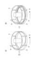
事前巻取工程S2では、事前巻取ドラム30に管状体20を巻き取る。本実施形態の事前巻取ドラム30は、支持台35の上に回転自在に取り付けられていて、鉛直な軸を中心にして回転する。詳細には、事前巻取ドラム30は、図3(A)に示されるように、支持台35の上に載置される円盤31と、円盤31の外周部から起立した複数の支柱32と、円筒状をなして複数の支柱32の下端部に内側から嵌まる包囲部33と、を備えた構造になっている。なお、本実施形態では、包囲部33が複数の支柱32より低くなっていることで、事前巻取ドラム30に巻き取られた管状体20が外側から視認され易くなり、巻き取り状態の確認が容易となる。In the pre-winding step S2, the
事前巻取ドラム30に管状体20を巻き取るには、まず、図3(A)に示されるように、管状体20の先端を包囲部33の内側に宛がう。そして、図3(B)→図4(A)→図4(B)の流れに示されるように、管状体20を事前巻取ドラム30の内側に送りながら、その送り速度に合わせて事前巻取ドラム30を回転させる。すると、管状体20が、テンションがかかってない状態で事前巻取ドラム30の内側に巻き取られる。なお、事前巻取ドラム30を回転させる代わりに、管状体20の送りに伴ってその管状体20に押された事前巻取ドラム30が勝手に回転してもよい。To wind the
本実施形態の事前巻取工程S2では、事前巻取ドラム30が上述の如く構成されたことにより、管状体20の巻き取りの初期段階では、管状体20(特に、管状体20の先端)が包囲部33に宛がわれることで事前巻取ドラム30の外側に拡がることが抑えられ、管状体20の巻き取りの終盤では、管状体20が複数の支柱32に囲まれることで事前巻取ドラム30の外側に拡がることが抑えられる。この事前巻取ドラム30では、事前巻取ドラム30の中が見やすくなるので、作業者が管状体20の巻き取る状態を確認し易くなる。In the pre-winding step S2 of this embodiment, the
図2に示されるように、安定化工程S3では、事前巻取ドラム30によって巻き取られた管状体20に架橋処理を施す。具体的には、本実施形態の架橋処理では、管状体20の管内に、90℃の温水を8時間流して、架橋剤による架橋反応を促進する。架橋処理が行われると、管状体20を構成する未架橋のポリエチレンが架橋ポリエチレンとなり、管状体20が安定化される。ここで、架橋処理の条件は、管状体20を構成する未架橋のポリエチレンを架橋ポリエチレンにできれば、特に限定されない。As shown in FIG. 2, in the stabilization step S3, a crosslinking treatment is performed on the
図2に示されるように、巻取工程S4では、安定化工程S3で安定化された管状体20を巻取ドラム40に巻き直す。具体的には、安定化された管状体20の先端を巻取ドラム40の外周面に固定してから、巻取ドラム40を回転させて、安定化された管状体20を巻取ドラム40の外側に巻き付ける。なお、巻取ドラム40は、その中心軸が水平となるように配置されて、その中心軸回りに回転駆動される。巻取ドラム40に巻き取られた安定化された管状体20は、巻取ドラム40から外された後、固定具15(図1参照)によって巻回状態に保持される。これにより、図1に示される樹脂管10が完成する。As shown in FIG. 2, in the winding step S4, the
ここで、上述した事前巻取ドラム30の内径は、巻取ドラム40の外径よりも大きくなっている。従って、事前巻取工程S2では、管状体20は、巻取工程S4よりも緩く巻き取られることになり、成形工程S1に次いで巻取工程S4が行われた後、安定化工程S3が行われる場合と比較して、安定化工程S3での管状体20の巻回が緩くなる。なお、具体的には、事前巻取ドラム30の内径は、1.2~5mであり、より好ましくは、1.5~3mとなっていて、巻取ドラム40の外径は、0.5~1mであり、より好ましくは、0.6~1mとなっている。Here, the inner diameter of the
このように、本実施形態の樹脂管10の製造方法では、まず、押出成形によって形成された管状体20が、テンションがかかっていない状態で事前巻取ドラム30の内側に巻き取られ、その後、架橋処理によって安定化されてから、巻取ドラム40に再巻き取りされる。この製造方法によれば、管状体20は、安定化される際、テンションをかけない状態で巻き取られているので、従来のように、管状体20を直線状に伸ばした状態で安定化する場合と比較して、狭いスペースで巻き癖を低減可能となる。また、本実施形態では、安定化工程S3において、管状体20が巻回された状態で行うことができるので、管状体20が直線状に伸ばされる場合と比較して、管状体20を長く(例えば、100m~1000m程度)形成することが可能となる。その結果、樹脂管10を、管長が長い巻回状態(例えば、50m~200m)として出荷することが可能となる。In this way, in the manufacturing method of the resin pipe 10 of this embodiment, first, the
[第2実施形態]
本実施形態の樹脂管10Vは、図5(A)に示されるように、本管11の外側が保温チューブ12で覆われた2層構造になっている。本管11は、上記第1実施形態と同様、架橋ポリエチレン管で構成されている。保温チューブ12は、ポリオレフィン系樹脂(ポリエチレン系樹脂、ポリプロピレン系樹脂等)、ポリスチレン系樹脂、ポリ塩化ビニル系樹脂、ポリエチレン酢酸ビニル共重合体樹脂等の熱可塑性樹脂の発泡体、ポリウレタン系樹脂等の熱硬化性樹脂の発泡体等から構成されている。保温チューブ12は、後述する被覆工程S31において、保温チューブ12を熱融着により形成するため、熱可塑性樹脂の発泡体で構成されることが好ましく、ポリオレフィン系樹脂(特に、ポリエチレン系樹脂)の発泡体で構成されることがより好ましい。ポリエチレン系樹脂の発泡体としては、架橋タイプと未架橋タイプの何れも用いることができ、架橋タイプを用いた場合、保温チューブ12の耐熱性を向上させることができる。 [Second embodiment]
The resin pipe 10V of this embodiment has a two-layer structure in which the outside of the main pipe 11 is covered with the heat-insulating tube 12, as shown in FIG. 5(A). The main pipe 11 is made of a cross-linked polyethylene pipe, as in the first embodiment. The heat-insulating tube 12 is made of a foam of thermoplastic resin such as polyolefin resin (polyethylene resin, polypropylene resin, etc.), polystyrene resin, polyvinyl chloride resin, polyethylene vinyl acetate copolymer resin, etc., or a foam of thermosetting resin such as polyurethane resin. Since the heat-insulating tube 12 is formed by heat fusion in the covering step S31 described later, the heat-insulating tube 12 is preferably made of a foam of thermoplastic resin, and more preferably made of a foam of polyolefin resin (particularly polyethylene resin). As the foam of polyethylene resin, either a cross-linked type or a non-cross-linked type can be used, and when a cross-linked type is used, the heat resistance of the heat-insulating tube 12 can be improved.
図5(B)には、樹脂管10Vの製造の流れが示されている。樹脂管10Vの製造方法では、成形工程S1、事前巻取工程S2、安定化工程S3が順番に行われる。そして、安定化工程S3が終了すると、被覆工程S31と仮巻取工程S32が順番に行われてから、巻取工程S4が行われる。成形工程S1、事前巻取工程S2、安定化工程S3及び巻取工程S4の内容は、上記第1実施形態と同様になっている。Figure 5 (B) shows the manufacturing flow of the plastic pipe 10V. In the manufacturing method of the plastic pipe 10V, the molding process S1, the pre-winding process S2, and the stabilization process S3 are performed in that order. Then, when the stabilization process S3 is completed, the covering process S31 and the temporary winding process S32 are performed in that order, and then the winding process S4 is performed. The contents of the molding process S1, the pre-winding process S2, the stabilization process S3, and the winding process S4 are the same as those of the first embodiment.
図6に示されるように、被覆工程S31では、安定化工程S3で安定化された管状体20の外周面が断熱シート50で被覆される。具体的には、安定化された管状体20と断熱シート50とが被覆装置51に送給される。被覆装置51では、断熱シート50が、幅方向の両端部を突き合わせるように丸められて、安定化された管状体20を外側から覆う筒状に形成される。そして、熱融着により、断熱シート50の幅方向の両端部どうしを接合して保温チューブ12を形成すると共に、その保温チューブ12を安定化された管状体20の外周面に固定する。これにより、安定化された管状体20の外側が保温チューブ12で覆われた2層管20Vが形成される。As shown in FIG. 6, in the covering step S31, the outer peripheral surface of the
図6に示されるように、仮巻取工程S32では、被覆工程S31で形成された2層管20Vが仮巻取ドラム60に巻き取られる。仮巻取ドラム60は、事前巻取ドラム30(図3(A)参照)と同様の構造になっていて、支持台65の上に回転自在に取り付けられている。なお、具体的には、仮巻取ドラム60の内径は、1~2mとなっていて、事前巻取ドラム30の内径よりも小さく、巻取ドラム40の内径よりも大きいことが好ましい。また、仮巻取ドラム60として、事前巻取ドラム30と同じものを使用してもよい。As shown in FIG. 6, in the temporary winding step S32, the two-layer tube 20V formed in the covering step S31 is wound onto a temporary winding drum 60. The temporary winding drum 60 has a structure similar to that of the pre-winding drum 30 (see FIG. 3(A)), and is rotatably mounted on a support base 65. Specifically, the inner diameter of the temporary winding drum 60 is 1 to 2 m, which is preferably smaller than the inner diameter of the
本実施形態の巻取工程S4では、仮巻取工程S32で仮巻取ドラム60に巻き取られた2層管20Vを巻取ドラム40に巻き直す。そして、巻取ドラム40に巻き取られた2層管20Vが、巻取ドラム40から外された後、固定具15(図1参照)によって巻回状態に保持されると、図5(A)に示される樹脂管10Vが完成する。なお、樹脂管10Vの本管11は、安定化された管状体20によって構成される。In the winding step S4 of this embodiment, the two-layered tube 20V wound around the temporary winding drum 60 in the temporary winding step S32 is rewound around the winding drum 40. The two-layered tube 20V wound around the winding drum 40 is then removed from the winding drum 40 and held in a wound state by the fixing device 15 (see FIG. 1), completing the plastic tube 10V shown in FIG. 5(A). The main tube 11 of the plastic tube 10V is composed of the stabilized
[第3実施形態]
本実施形態では、樹脂管10がポリブテン管となっている。本実施形態の樹脂管10の製造方法は、安定化工程S3の内容のみが上記第1実施形態と異なっている。 [Third embodiment]
In this embodiment, a polybutene pipe is used as the resin pipe 10. The method for producing the resin pipe 10 of this embodiment differs from the first embodiment only in the content of the stabilization step S3.
本実施形態の安定化工程S3では、事前巻取工程S2で事前巻取ドラム30に巻き取られた管状体20に、養生処理を施す。この養生処理は、管状体20を常温で約1週間放置する。なお、養生処理によって、管状体20を構成するポリブテンは、準安定な固相状態から安定な固相状態となる。In the stabilization step S3 of this embodiment, a curing process is performed on the
[他の実施形態]
(1)上記第1、第2実施形態では、架橋処理において、管状体20の管内に温水を流していたが、管状体20の管内に水蒸気を流してもよい。また、管状体20の管内に温水又は水蒸気を流しながら、管状体20の周囲に水蒸気を送り込んでもよい。 [Other embodiments]
(1) In the above first and second embodiments, warm water is flowed inside the tube of the
(2)上記第1、第2実施形態の安定化工程S3において、架橋処理の後に、さらに養生処理を行ってもよい。(2) In the stabilization step S3 of the first and second embodiments, a curing process may be further performed after the crosslinking process.
(3)上記第2実施形態では、架橋ポリエチレン管からなる本管11の外側を熱可塑性樹脂等の発泡体からなる保温チューブ12で覆って2層構造としていたが、熱可塑性エラストマーからなる保護層や予め形成された架橋ポリエチレンパイプからなる保護管等で覆って2層構造としてもよい。本管11と保護層との一体化は、本管11の外周部に押出機を用いて溶融状態の熱可塑性エラストマーを直接押し出し、被覆させればよい。本管11と保護管との一体化は、あらかじめ形成された保護管内に本管11を挿入すればよい。(3) In the second embodiment described above, the outside of the main pipe 11 made of a cross-linked polyethylene pipe is covered with an insulation tube 12 made of a foam such as a thermoplastic resin to form a two-layer structure, but it may also be covered with a protective layer made of a thermoplastic elastomer or a protective tube made of a pre-formed cross-linked polyethylene pipe to form a two-layer structure. The main pipe 11 and the protective layer can be integrated by directly extruding a molten thermoplastic elastomer onto the outer periphery of the main pipe 11 using an extruder to cover it. The main pipe 11 and the protective tube can be integrated by inserting the main pipe 11 into a pre-formed protective tube.
(4)上記第2実施形態では、被覆工程S31で形成された2層管20Vを、仮巻取工程S32で仮巻き取りした後、巻取工程S4で巻き直しを行ったが、被覆工程S31に次いで仮巻取工程S32を行わず、直接、巻取工程S4を行ってもよい。(4) In the second embodiment described above, the two-layer tube 20V formed in the covering process S31 is temporarily wound in the temporary winding process S32 and then rewound in the winding process S4. However, the winding process S4 may be performed directly after the covering process S31 without performing the temporary winding process S32.
(5)上記第1~第3実施形態において、巻取ドラム40における安定化された管状体20又は2層管20Vの巻き取りは、事前巻取ドラム30における管状体20の巻き取りと同じ方向であっても逆方向であってもよい。また、上記第2実施形態において、仮巻取ドラム60における2層管20Vの巻き取りは、事前巻取ドラム30における管状体20の巻き取りと同じ方向であっても逆方向であってもよいし、巻取ドラム40における2層管20Vの巻き取りは、仮巻取ドラム60における2層管20Vの巻き取りと同じ方向であっても逆方向であってもよい。(5) In the first to third embodiments, the stabilized
(6)上記第1~第3実施形態では、安定化された管状体20又は2層管20Vを巻取ドラム40の外周面に固定して巻取ドラム40の外側に巻き付けていたが、事前巻取ドラム30のように、巻取ドラム40の内側に巻き付けてもよい。その際、安定化された管状体20又は2層管20Vにテンションをかけながら巻き付けると、安定化された管状体20又は2層管20Vをきれいに巻くことができる。(6) In the above first to third embodiments, the stabilized
(7)上記第1~第3実施形態では、事前巻取ドラム30の包囲部33が円筒状であったが、管状体20を巻き取ることができれば、多角形の筒状(例えば、六角形以上の筒状)であってもよい。(7) In the first to third embodiments, the enclosing
(8)上記第1~第3実施形態では、事前巻取ドラム30の包囲部33の高さが複数の支柱32より低かったが、複数の支柱32の高さ以上であってもよい。その際、包囲部33の周方向の一部に、上方に開放した切欠部を設けておけば、その切欠部を通して、事前巻取ドラム30に巻き取られた管状体20を外側から視認することができる。(8) In the first to third embodiments, the height of the enclosing
(9)包囲部33は、筒体における周方向の一部が切除された形状(例えば、平面視C字状)であってもよい。この場合であっても、切除された部分が管状体20の管径よりも十分に小さければ、その切除された部分に管状体20を引っ掛けることなく管状体20を巻き取ることが可能となる。(9) The surrounding
10,10V 樹脂管
20 管状体
30 事前巻取ドラム
40 巻取ドラム
S1 成形工程
S2 事前巻取工程
S3 安定化工程
S4 巻取工程 10,
Claims (7)
Translated fromJapanese押出成形によって樹脂製管状体を形成する成形工程と、
前記管状体を事前巻取ドラムの内側に巻き取る事前巻取工程と、
前記事前巻取ドラムに巻き取られた状態の前記管状体に架橋処理又は養生処理を施して該管状体を安定化させる安定化工程と、
を備える樹脂管の製造方法。 A method for manufacturing a resin pipe, comprising the steps of:
a molding step of forming a resin tubular body by extrusion molding;
a pre-winding step of winding the tubular body on an inner side of a pre-winding drum;
a stabilization step of stabilizing the tubular body by subjecting the tubular body in a state of being wound around the pre-winding drum to a crosslinking treatment or a curing treatment;
A method for manufacturing a resin pipe comprising the steps of:
(A)前記樹脂管がポリブテン製である、
又は、
(B)巻取ドラムの内側に巻いた状態で架橋処理又は養生処理を施す、
樹脂管の製造方法。 A methodfor manufacturing a resin pipe in which the pipe is wound without tension and crosslinked or cured,
(A) the resin tube is made of polybutene;
Or,
(B) A crosslinking treatment or curing treatment is performed while the film is wound around the inside of a winding drum.
A method for manufacturing plastic pipes.
(A)前記樹脂管がポリブテン製である、
又は、
(B)巻取ドラムの内側に巻いた状態で架橋処理又は養生処理を施す、
樹脂管の巻癖低減方法。 A methodfor reducing winding tendencies in a resin pipe, which is wound without tension and crosslinked or cured, comprising the steps of:
(A) the resin tube is made of polybutene;
Or,
(B) A crosslinking treatment or curing treatment is performed while the film is wound around the inside of a winding drum .
A method for reducing the curl of plastic pipes.
Priority Applications (1)
| Application Number | Priority Date | Filing Date | Title |
|---|---|---|---|
| JP2022154600AJP7524265B2 (en) | 2018-09-19 | 2022-09-28 | Manufacturing method of resin pipe and method for reducing winding tendency of resin pipe |
Applications Claiming Priority (2)
| Application Number | Priority Date | Filing Date | Title |
|---|---|---|---|
| JP2018174491AJP7150540B2 (en) | 2018-09-19 | 2018-09-19 | Method for manufacturing resin pipe |
| JP2022154600AJP7524265B2 (en) | 2018-09-19 | 2022-09-28 | Manufacturing method of resin pipe and method for reducing winding tendency of resin pipe |
Related Parent Applications (1)
| Application Number | Title | Priority Date | Filing Date |
|---|---|---|---|
| JP2018174491ADivisionJP7150540B2 (en) | 2018-09-19 | 2018-09-19 | Method for manufacturing resin pipe |
Publications (2)
| Publication Number | Publication Date |
|---|---|
| JP2022173418A JP2022173418A (en) | 2022-11-18 |
| JP7524265B2true JP7524265B2 (en) | 2024-07-29 |
Family
ID=69899423
Family Applications (2)
| Application Number | Title | Priority Date | Filing Date |
|---|---|---|---|
| JP2018174491AActiveJP7150540B2 (en) | 2018-09-19 | 2018-09-19 | Method for manufacturing resin pipe |
| JP2022154600AActiveJP7524265B2 (en) | 2018-09-19 | 2022-09-28 | Manufacturing method of resin pipe and method for reducing winding tendency of resin pipe |
Family Applications Before (1)
| Application Number | Title | Priority Date | Filing Date |
|---|---|---|---|
| JP2018174491AActiveJP7150540B2 (en) | 2018-09-19 | 2018-09-19 | Method for manufacturing resin pipe |
Country Status (1)
| Country | Link |
|---|---|
| JP (2) | JP7150540B2 (en) |
Families Citing this family (2)
| Publication number | Priority date | Publication date | Assignee | Title |
|---|---|---|---|---|
| JP2021143752A (en)* | 2020-03-13 | 2021-09-24 | 三菱ケミカルインフラテック株式会社 | Method of producing crosslinked polyolefin tube |
| JP7484330B2 (en)* | 2020-03-30 | 2024-05-16 | 三菱ケミカルインフラテック株式会社 | Manufacturing method of coated pipe |
Citations (5)
| Publication number | Priority date | Publication date | Assignee | Title |
|---|---|---|---|---|
| JP2002103339A (en) | 2000-09-29 | 2002-04-09 | Tokai Rubber Ind Ltd | Rubber hose continuous vulcanization equipment and method for producing rubber hose using the same |
| JP2004044733A (en) | 2002-07-12 | 2004-02-12 | Furukawa Electric Co Ltd:The | Composite pipe and method of manufacturing the same |
| JP2005344820A (en) | 2004-06-02 | 2005-12-15 | Mirai Kk | Method of manufacturing synthetic resin long size water feeding pipe and synthetic resin long size water feeding pipe |
| JP2010254834A (en) | 2009-04-27 | 2010-11-11 | Sekisui Chem Co Ltd | Method for producing cross-linked polyethylene pipe and cross-linking apparatus used in this method |
| JP2017044338A (en) | 2015-08-27 | 2017-03-02 | 株式会社ブリヂストン | Resin pipe, resin pipe manufacturing method, and piping structure |
Family Cites Families (4)
| Publication number | Priority date | Publication date | Assignee | Title |
|---|---|---|---|---|
| JPH10299955A (en)* | 1997-04-21 | 1998-11-13 | Mitsubishi Cable Ind Ltd | Rigid plastic pipe and its transfer method |
| JPH10332054A (en)* | 1997-05-28 | 1998-12-15 | Mitsubishi Cable Ind Ltd | Rigid plastic pipe and its transfer method |
| JP4004889B2 (en) | 2002-08-09 | 2007-11-07 | 未来工業株式会社 | Long material packaging equipment |
| EP2845832B1 (en) | 2013-09-05 | 2017-07-26 | KONE Corporation | A rope storage unit, a method for installing elevator and a method for fabricating rope storage unit |
- 2018
- 2018-09-19JPJP2018174491Apatent/JP7150540B2/enactiveActive
- 2022
- 2022-09-28JPJP2022154600Apatent/JP7524265B2/enactiveActive
Patent Citations (5)
| Publication number | Priority date | Publication date | Assignee | Title |
|---|---|---|---|---|
| JP2002103339A (en) | 2000-09-29 | 2002-04-09 | Tokai Rubber Ind Ltd | Rubber hose continuous vulcanization equipment and method for producing rubber hose using the same |
| JP2004044733A (en) | 2002-07-12 | 2004-02-12 | Furukawa Electric Co Ltd:The | Composite pipe and method of manufacturing the same |
| JP2005344820A (en) | 2004-06-02 | 2005-12-15 | Mirai Kk | Method of manufacturing synthetic resin long size water feeding pipe and synthetic resin long size water feeding pipe |
| JP2010254834A (en) | 2009-04-27 | 2010-11-11 | Sekisui Chem Co Ltd | Method for producing cross-linked polyethylene pipe and cross-linking apparatus used in this method |
| JP2017044338A (en) | 2015-08-27 | 2017-03-02 | 株式会社ブリヂストン | Resin pipe, resin pipe manufacturing method, and piping structure |
Also Published As
| Publication number | Publication date |
|---|---|
| JP2022173418A (en) | 2022-11-18 |
| JP2020045961A (en) | 2020-03-26 |
| JP7150540B2 (en) | 2022-10-11 |
Similar Documents
| Publication | Publication Date | Title |
|---|---|---|
| JP7524265B2 (en) | Manufacturing method of resin pipe and method for reducing winding tendency of resin pipe | |
| JP5592078B2 (en) | Insulated hose and method for manufacturing the same | |
| KR101166886B1 (en) | Metal-resin complex pipe easily windable in ring shape and, manufacturing methods for the same | |
| US20180229449A1 (en) | Gas tank and method of manufacturing gas tank | |
| US20110194825A1 (en) | Method of forming an optical fiber buffer tube | |
| NO321099B1 (en) | Support for an elastic sleeve | |
| US20100170590A1 (en) | Manufacturing a piping element, and piping element | |
| JPH01195026A (en) | Method and device for manufacturing composite tube | |
| JP2008062533A (en) | Manufacturing method of heat insulation duct hose | |
| JP6706158B2 (en) | Manufacturing method of composite pipe | |
| EP2113375A1 (en) | Ventilation duct | |
| US3089535A (en) | Apparatus for making a wire reinforced flexible hose | |
| CN101195274A (en) | Adhesive applicator and method of manufacturing heat-shrinkable tubes using the same | |
| RU2019116336A (en) | EXPANDABLE CORRUGATED HOSE AND METHOD OF ITS MANUFACTURE | |
| US2577427A (en) | Insulating covering | |
| JP2011123393A (en) | Plastic clad optical fiber cord | |
| US2633983A (en) | Motion-picture film reel band | |
| JP4590212B2 (en) | Manufacturing method of long water pipe made of synthetic resin | |
| JPS5810223B2 (en) | Manufacturing method for heat-insulating and sound-insulating pipes | |
| JPS5928800B2 (en) | Manufacturing method of insulated pipes | |
| JPS635256B2 (en) | ||
| JPH0751639B2 (en) | Cord-shaped or rod-shaped prepreg hollow body | |
| JP3522320B2 (en) | Cable protection tube, its manufacturing apparatus and its manufacturing method | |
| HUP0003237A2 (en) | Pipe shell insulating pipe, arrangments for insulating pipes and method for manufacturing pipe shell | |
| US4493464A (en) | Packaged strand |
Legal Events
| Date | Code | Title | Description |
|---|---|---|---|
| A521 | Request for written amendment filed | Free format text:JAPANESE INTERMEDIATE CODE: A523 Effective date:20221027 | |
| A621 | Written request for application examination | Free format text:JAPANESE INTERMEDIATE CODE: A621 Effective date:20221027 | |
| A977 | Report on retrieval | Free format text:JAPANESE INTERMEDIATE CODE: A971007 Effective date:20230920 | |
| A131 | Notification of reasons for refusal | Free format text:JAPANESE INTERMEDIATE CODE: A131 Effective date:20230926 | |
| A521 | Request for written amendment filed | Free format text:JAPANESE INTERMEDIATE CODE: A523 Effective date:20231127 | |
| A131 | Notification of reasons for refusal | Free format text:JAPANESE INTERMEDIATE CODE: A131 Effective date:20240130 | |
| A521 | Request for written amendment filed | Free format text:JAPANESE INTERMEDIATE CODE: A523 Effective date:20240401 | |
| TRDD | Decision of grant or rejection written | ||
| A01 | Written decision to grant a patent or to grant a registration (utility model) | Free format text:JAPANESE INTERMEDIATE CODE: A01 Effective date:20240716 | |
| A61 | First payment of annual fees (during grant procedure) | Free format text:JAPANESE INTERMEDIATE CODE: A61 Effective date:20240717 | |
| R150 | Certificate of patent or registration of utility model | Ref document number:7524265 Country of ref document:JP Free format text:JAPANESE INTERMEDIATE CODE: R150 |